
ACP VC1 D - Controller Extron - Free user manual and instructions
Find the device manual for free ACP VC1 D Extron in PDF.


| Product Type | Audio Control Panel |
| Brand | Extron |
| Model | ACP VC1 D |
| Dimensions (approx) | 4.5" x 2.75" x 1.5" (US 1-gang) |
| Weight (approx) | 0.5 lb (0.23 kg) |
| Power | Powered via host device or optional 12 VDC power supply (PS 1220EB) |
| Ports | 2 ACP ports (4-pole captive screw connectors) |
| Functions | Volume control knob, mute button, status LED, configurable via DSP Configurator |
| Bus ID | 6-bit DIP switch, up to 8 unique addresses |
| Compatibility | Works with Extron ACP-enabled host devices |
| Installation | Requires UL Listed junction box or mud ring for wall mounting |
| Maintenance | Clean with dry cloth; do not use liquids or solvents |
| Spare Parts | Replacement faceplates and buttons available from Extron |
| Repairability | Buttons and faceplate replaceable; no user-serviceable internal parts |
| Safety | Must be installed in UL Listed junction box; comply with NEC and ADA |
Frequently Asked Questions - ACP VC1 D Extron
User questions about ACP VC1 D Extron
0 question about this device. Answer the ones you know or ask your own.
Ask a new question about this device
Download the instructions for your Controller in PDF format for free! Find your manual ACP VC1 D - Extron and take your electronic device back in hand. On this page are published all the documents necessary for the use of your device. ACP VC1 D by Extron.
USER MANUAL ACP VC1 D Extron
The Extron ACP VC1 D Audio Control Panel is a fully configurable control interface for use with any Extron ACP-enabled device.
Each ACP VC1 D includes two ACP ports, which support power and communication between the host device and the ACP VC1 D. Up to eight ACP panels can be used per host device for more demanding control needs.
Planning System Installation
When planning an ACP system installation, consider how many ACP panels to use, maximum cable distance, and mounting (see the ACP VC1 D product page at www.extron.com for more information regarding the ACP VC1 D).

Figure 1. ACP VC1 D
A Front Panel Rotary Volume Knob
B Front Panel Mute Button
© ACP Ports (2)

D Connection Status LED
E Reset Button
F Bus ID DIP Switches

Installation
Step 1: Get Ready
Use the following checklist to prepare for installation:
☐ Download and install the latest software, firmware, and device drivers needed to configure the host device and the connected ACP devices (see the host device user guide, available at www.extron.com, for details regarding software and drivers).
☐ Obtain cables, mounting hardware, and any other supplies required for the installation.
Step 2: Prepare the Installation Site
ATTENTION:
NOTE: For the installation to meet UL requirements and comply with National Electrical Code (NEC), the ACP VC1 D must be installed in a UL Listed junction box. The end user or installer must furnish the junction box. It is not included with the ACP VC1 D.
Americans with Disabilities Act (ADA) Compliance
When planning where to install these devices, consider factors affecting accessibility of the button panel such as height from the floor, distance from obstructions, and how far a user must reach to press the buttons. For guidelines, see sections 307 ("Protruding Objects") and 308 ("Reach Ranges") of the 2010 ADA Standards for Accessible Design available at http://www.ada.gov/regs2010/2010ADAStandards/2010ADAStandards.pdf.
Site Preparation
Extron offers an assortment of mud rings, optional UL Listed in-wall junction boxes, external wall boxes (EWBs), and surface or tabletop mounting boxes for use with the ACP button panels. The ACP VC1 D is a US 1-gang size device.
Step 3: Removing the Plastic Faceplate, Removing the Button Panel, and Changing the Button
The plastic faceplate and button can be replaced. Additional buttons ship with the device and others can be ordered from www.extron.com.
To change the button:
- Remove the two screws holding the plastic faceplate to the metal mounting plate and separate the faceplate from the button plate (see ① in the figure to the right).
- Insert a small flat-bladed screw driver into the notch at the top of the button plate. Release the catch holding the button plate to the metal mounting plate (②).
- Repeat step 2 to release the catch at the bottom of the plate.
- Tilt the top of the button plate forward as it is removed to prevent the button from falling out.

- To remove the button, press the button backward through its slot in the button plate until the membrane containing the button is free (see 1 in the figure to the right).
- To replace the button, align the two pegs in the button membrane with the holes located at opposite corners of the empty slot on the back of the button faceplate and push the button forward so it fits in the slot (2). Ensure the button text orientation is correct.
- Align the button plate with the metal mounting plate using the pegs on the rear of the button plate as guides.
- Snap the button plate into place.
- Reattach the plastic faceplate using the two screws removed in step 1 on the previous page.
Step 4: Set Bus ID Address
Set the bus identification (bus ID) DIP switches for the ACP VC1 D and any other ACP panels being connected to the system. Each ACP device must have a unique bus ID. If multiple panels have the same bus ID, address conflicts may cause one or more of the panels to not be recognized in DSP Configurator or by the host device. Up to eight ACP devices can be connected in the same system.

![Bus ID Address DIP Switches • Use these DIP switches to set the six-bit, binary bus address for the ACP 100. • Each ACP connected to the same DMP 128 Plus must have a unique address. • Switch 1 (on the left) is the highest value (32, the most significant bit [labeled "MSB"]). • Switch 6 (on the right) is the lowest (1, the least significant bit [labeled "LSB-)]. • Up = on = 1, Down = off = 0 Examples: Unit address 1 18 DIP switches CN CN Binary address 0 0 0 0 0 1 0 1 0 0 1 0 ACP Ports • Connect up to eight (8) ACP endpoint devices per DMP 128 Plus. • Wire the connectors the same at both ends. • These ports are identical. You can connect devices interchangeably to either port. • Do not exceed a total of 1000 feet (305 meters) of cable for connections between the DMP 128 Plus and all of the ACP panels. • Power is provided by the IPCP Pro, a PS 1220EB power inserter, or an Extron 12 VDC power supply. ACP port on a DMP 128 Plus, or on another ACP endpoint](/content/2026/05/1064292/images/ac3c2ff35a877b42d42762e8725a7d2e63f6423b6c6751784f49ede7469d403e.jpg)
Setting the Bus ID Address
Each ACP device in a system must have a unique six-digit binary bus ID. ACP bus IDs are set using the DIP switch assembly on the left side of the ACP VC1 D (see E on figure 1 at the beginning of the guide).
Switch 1 on the left sets the most significant bit (highest number, 32) while switch 6 on the right sets the least significant bit (the lowest number, 1). See the example addresses to the right.
Step 5: Cable All Devices
- Connect the ACP panel to the host device.
- Connect ACP panels to each other if multiple panels are used in the system (see the wiring diagram below for correct wiring).
NOTES:
- Wire both ends of each ACP cable the same. Connectors are interchangeable between the host device and ACP devices.
-
Do NOT power an ACP panel from more than one power source.
-
Apply power to the host device after correctly cabling all devices.
Cabling
Attach cables using the diagram below as a guide. Wiring is the same for all ACP models. Connect a 4-pole captive screw connector to each end of the cable, wiring both ends the same. In most cases, ACP devices are powered by the host device. Power is carried on the V+ pin of the ACP VC1 D and other ACP devices.
Extron STP20-2/1000 or STP20-2P/100 cable is recommended for ACP device connections.
ACP devices that are relatively far from the host device can be connected to an optional Extron PS 1220EB eBUS power inserter or an Extron 12 VDC desktop power supply as shown in the diagrams below and on the next page (see the ACP VC1 D Specifications at www.extron.com to determine if additional power is recommended).
| Example Addresses | ||
| Bus ID(Decimal) | Binary Address | DIP Switch Setting |
| 0 000000* *Reserved(for controller address) | [IMAGE] | |
| 1 000001 | [IMAGE] | |
| 2 000010 | [IMAGE] | |
| 3 000011 | [IMAGE] | |
| 4 000100 | [IMAGE] | |
| 5 000101 | [IMAGE] | |
| 6 000110 | [IMAGE] | |
| 7 000111 | [IMAGE] | |
| 8 001000 | [IMAGE] | |

ATTENTION:

Step 6: Configure the System
NOTE: For complete information on creating configuration files and operating DSP Configurator Software, see the host device user guide or refer to the DSP Configurator Software product page at www.extron.com.
- Create a new host device configuration file in DSP Configurator and create all groups, presets, and macros to be controlled by the ACP device.
- Select Tools>Configure ACPs in DSP Configurator and configure the ACP button actions and panel IDs.
- Connect to the host device in Live mode with a TCP/IP connection and push the configuration file to the device.
Step 7: Test and Troubleshoot
- Verify the ACP bus ID DIP switches are set to the desired address on each unit and that there are no bus ID address conflicts in the system. As mentioned in the rear panel features diagram in step 4 (see page 3), the ACP LED lights green when power and communication are present and there are no bus ID address conflicts. Refer to the legend on the back of the panel for other LED behavior indications.
- Verify cables to and from the ACP devices are wired the same at each end.
- Test the system:
a. Press the ACP device button and ensure the button lights as expected and that the appropriate control actions are triggered. Commands can be verified using DSP Configurator. DataViewer can also be used for command verification if responses are configured.
b. Ensure the audio levels respond correctly to the rotary volume control and mute button.
- Make adjustments to wiring, bus ID addresses, and system configuration as needed. Remember that the rear panel ports and DIP switches are not accessible after the ACP is mounted. If needed, push a revised configuration to the ACP device through the host device using DSP Configurator.
If you have questions during installation and setup, call the Extron S3 Sales and Technical Support Hotline or the Extron S3 Control Systems Support Hotline (1.800.633.9877).
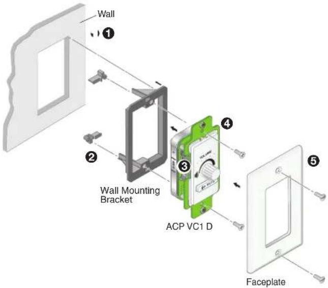
Step 8: Mounting the ACP VC1 D
Prior to mounting:
- Feed all device cables through the wall or furniture.
NOTE: If the unit is not installed in a mud ring, the plastic spacer must be installed. The spacer positions the unit to allow the plastic faceplate to attach properly and securely.
- Ensure the cables are connected to the ACP VC1 D rear panel.
To mount an ACP VC1 D with a wall mounting bracket (mud ring):
- Mark the position of the hole for the wallplate on desired wall location. Use a level to ensure the hole is marked at the correct angle.
- Use a drywall saw to cut the hole for the wall mounting bracket (see ① in the figure to the right).
- Insert the wall mounting bracket (mud ring) into the hole and use a screw driver to turn and tighten the locking arms until they clamp the mud ring to the mounting surface (2). Do not overtighten.
- If not already done, set bus ID DIP switches so the panel has a unique bus ID (③).
- Use the two provided screws to secure the metal mounting plate to the mud ring (4).
- Use the other two provided screws to secure the plastic faceplate to the metal mounting plate (5).
To mount an ACP VC1 D with a junction box:
- Install the junction box following the instructions provided with the chosen junction box. No junction box is included with the ACP VC1 D.
- Locate a suitable wall stud and mark the location of the hole on the wall. Use a level to ensure the hole is marked at the correct angle.
- Use a drywall saw to cut the hole. Follow the instructions of the junction box manufacturer for the correct dimensions of the hole. Use at least two screws or nails to secure the box to the wall or stud. Follow steps 4 through 6 above to complete the installation.

For information on safety guidelines, regulatory compliances, EMI/EMF compatibility, accessibility, and related topics, see the Extron Safety and Regulatory Compliance Guide on the Extron website.


- Planning System Installation
- Installation
- Step 1: Get Ready
- Step 2: Prepare the Installation Site
- ATTENTION:
- Americans with Disabilities Act (ADA) Compliance
- Site Preparation
- Step 3: Removing the Plastic Faceplate, Removing the Button Panel, and Changing the Button
- To change the button:
- Step 4: Set Bus ID Address
- Setting the Bus ID Address
- Step 5: Cable All Devices
- NOTES:
- Cabling
- Step 6: Configure the System
- Step 7: Test and Troubleshoot
- Step 8: Mounting the ACP VC1 D
- Prior to mounting:
- To mount an ACP VC1 D with a wall mounting bracket (mud ring):
- To mount an ACP VC1 D with a junction box:
Brand : Extron
Model : ACP VC1 D
Category : Controller