
VRFBM-77i - Unspecified CRUX - Free user manual and instructions
Find the device manual for free VRFBM-77i CRUX in PDF.


| Product Type | Vehicle Radio Replacement Interface |
| Brand | CRUX |
| Model | VRFBM-77i |
| Compatible Vehicles | Select BMW and Mini models (2002-2010) |
| Dimensions | 2.5 x 1.5 x 0.5 inches (63.5 x 38.1 x 12.7 mm) |
| Weight | 0.2 lbs (90 g) |
| Power Supply | 12V DC, <500 mA |
| Primary Functions | Retain factory features (steering wheel controls, Bluetooth, AUX), provide data bus integration for aftermarket radios |
| Input/Output | ISO connectors, vehicle-specific harness, signal wires for steering wheel control and speed pulse |
| Installation | Plug-and-play with soldered connections; requires vehicle-specific wiring adapters |
| Compatibility | Works with most aftermarket CD/DVD/Navigation receivers |
| Cleaning and Maintenance | Wipe with a dry, soft cloth. Avoid liquids and cleaners. |
| Safety Precautions | Disconnect vehicle battery negative terminal before installation to prevent short circuits. |
| Spare Parts and Repairability | No user-serviceable parts. Contact CRUX support for module replacement. |
| Warranty | 1-year limited warranty against defects |
| Manufacturer | CRUX Interfacing Solutions |
| Package Contents | Module, harness, instruction manual |
| Operating Temperature | -22°F to 185°F (-30°C to 85°C) |
Frequently Asked Questions - VRFBM-77i CRUX
User questions about VRFBM-77i CRUX
0 question about this device. Answer the ones you know or ask your own.
Ask a new question about this device
Download the instructions for your Unspecified in PDF format for free! Find your manual VRFBM-77i - CRUX and take your electronic device back in hand. On this page are published all the documents necessary for the use of your device. VRFBM-77i by CRUX.
USER MANUAL VRFBM-77i CRUX
Vehicle Applications
BMW
2015-2016 i3*
Product Features
- With OE type Dynamic Parking Guide Lines
- On-screen display and setup
- 2 trigger outputs (+12V max. 1A), separately adjustable switching events (CAN, ACC, rear-view camera, reverse gear)
• Rear-view camera input - Front camera input
- Front camera input can also be used as an Auxiliary Video Input
• Automatic switching to rear-view camera input on engagement of reverse gear from all operation modes - Forced rear-view camera option (only on vehicles with PDC button)
- Manual return from rear-view and front camera (cancellation of automatic switching)
- Picture-in-picture mode combining after-market rear-view and front camera picture(s) with factory parking sensor graphics
- Compatible with all factory video accessories (e.g. rear-view camera, DVD-changer, etc.)
- Plug & Play installation
Navigation / Radio Compatibility
- For the BMW i3 with navigation system or radio and 6.5", 7", 8.8" or 10.25" monitor with 4+2pin HSD2 LVDS connector
Notes
- The interface is installed under the glove compartment and the radio headunit is located under the rear seat.
Parts Included

BM-77i Module

BM-77i Harness

4+2 PIN HSD2 LVDS Cable

Power/CAN Harness
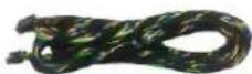
i3-HAR
1/11
Rev.112816
Crux Interfacing Solutions
www.cruxinterfacing.com

tel. #: (818) 609-9299
fax #: (818) 996-8188
Wiring Diagram

flowchart
graph TD
    A["VRFBM-77i Module"] --> B["4+2 PIN HSD2 LVDS Female Vehicle Harness"]
    A --> C["Back of Factory Monitor"]
    A --> D["Male Quadlock on the Rear of the NBT Unit"]
    A --> E["Interface Box Front View"]
    A --> F["Power/CAN Harness"]
    A --> G["Front Camera (Not Included)"]
    A --> H["Back View Camera (Not Included)"]
    A --> I["DVD Player* (Not Included)"]
    A --> J["Portable Video Player* (Not Included)"]
    A --> K["Motor Control Panel"]
    A --> L["Motor Control Panel"]
    A --> M["Motor Control Panel"]
    A --> N["Motor Control Panel"]
    A --> O["Motor Control Panel"]
    A --> P["Motor Control Panel"]
    A --> Q["Motor Control Panel"]
    A --> R["Motor Control Panel"]
    A --> S["Motor Control Panel"]
    A --> T["Motor Control Panel"]
    A --> U["Motor Control Panel"]
    A --> V["Motor Control Panel"]
    A --> W["Motor Control Panel"]
    A --> X["Motor Control Panel"]
    A --> Y["Motor Control Panel"]
    A --> Z["Motor Control Panel"]
    A --> AA["Motor Control Panel"]
    A --> AB["Motor Control Panel"]
    A --> AC["Motor Control Panel"]
    A --> AD["Motor Control Panel"]
    A --> AE["Motor Control Panel"]
    A --> AF["Motor Control Panel"]
    A --> AG["Motor Control Panel"]
    A --> AH["Motor Control Panel"]
    A --> AI["Motor Control Panel"]
    A --> AJ["Motor Control Panel"]
    A --> AK["Motor Control Panel"]
    A --> AL["Motor Control Panel"]
    A --> AM["Motor Control Panel"]
    A --> AN["Motor Control Panel"]
    A --> AO["Motor Control Panel"]
    A --> AP["Motor Control Panel"]
    A --> AQ["Motor Control Panel"]
    A --> AR["Motor Control Panel"]
    A --> AS["Motor Control Panel"]
    A --> AT["Motor Control Panel"]
    A --> AU["Motor Control Panel"]
    A --> AV["Motor Control Panel"]
    A --> AW["Motor Control Panel"]
    A --> AX["Motor Control Panel"]
    A --> AY["Motor Control Panel"]
    A --> AZ["Motor Control Panel"]
    A --> BA["Motor Control Panel"]
    A --> BB["Motor Control Panel"]
    A --> BC["Motor Control Panel"]
    A --> BD["Motor Control Panel"]
    A --> BE["Motor Control Panel"]
    A --> BF["Motor Control Panel"]
    A --> BG["Motor Control Panel"]
    A --> BH["Motor Control Panel"]
    A --> BI["Motor Control Panel"]
    A --> BJ["Motor Control Panel"]
    A --> BK["Motor Control Panel"]
    A --> BL["Motor Control Panel"]
    A --> BM["Harness: BM-77i"]
    BM -->|i3-HAR (10 Ft.)| BN
    BN -->|+12V Switching Output (Green Wire)| CA
    BN -->|Reverse Gear Signal Input +12V (White Wire)| CB
    BN -->|+12V Switching Input (Pink Wire)| CC
    BN -->|+12V Switching Output (Green Wire)| DD
    BN -->|Reverse Gear Signal Input +12V (White Wire)| DE
Installation Instructions
Setting the DIP switches of the Interface Box.
DIPs 1 and 2 on the back of the interface-box is used to set the monitor size. DIP 3 must be set to OFF.
| Vehicle/ Navigation | Dip 1 | Dip 2 | Dip 3 |
| 6.5" monitor. | OFF | OFF | No function |
| 7" monitor | OFF | OFF | No function |
| 8.8" monitor | ON | OFF | No function |
| 10.25" monitor (ver.1) | ON | OFF | No function |
| 10.25" monitor (ver.2) | ON | ON | No function |
After each change of the DIP switch settings you have to execute a power reset of the interface box!
Connecting Interface box and harnesses
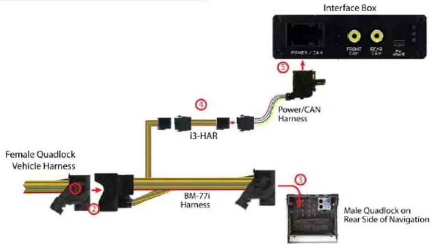
1 Remove the rear seat and locate the Radio Headunit. Unplug the Quadlock connector from the Radio Headunit.
2 Plug factory Quadlock connector into the BM-77i T-harness female Quadlock connector
3 Connect the male Quadlock connector of the BM-77i T-harness to the female Quadlock connector of the Radio Headunit.
4 Run the i3-HAR along the passenger side door sill from the Radio Headunit towards the glove compartment and plug it into the Power/CAN harness.
5 Connect the female 12pin AMP connector of the Power/CAN harness to the front side of the VRFBM-77i interface box.
LVDS Connection
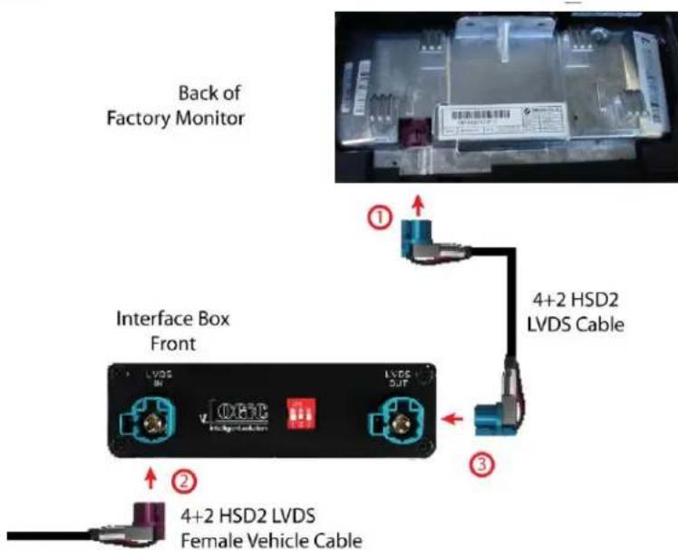
1 Connect the female 4+2pin HSD2 LVDS connector of the LVDS cable to the male 4+2pin HSD2 LVDS connector (LVDS-OUT) on the front of the VRFBM-77i interface box.
2 Remove the female 4+2pin HSD2 LVDS connector of the vehicle harness from the factory monitor and connect it to the male 4+2pin HSD2 LVDS connector (LVDS-IN) on the front of the VRFBM-77i Interface box.
3 Connect the second female 4+2pin HSD2 LVDS connector of the LVDS cable the male 4+2pin HSD2 LVDS connector of the factory monitor.
LEDs of the Interface-box

- Valid input source
CAN ok
Power
Connection to the aftermarket front camera


Connect the video RCA of the after-market front camera to the female RCA connector "FRONT CAM" of the interface box.

The pink wire of the Power/CAN harness can be used for +12V electric power supply (max. 1A) of the aftermarket front camera. Configure in the OSD-menu "MISC", Menu item "POWER OUT 1" the designated electric power supply (see chapter "Configurable switching outputs").

Settings for connecting an aftermarket front camera
You have to configure some settings in the OSD-menu's INPUTS and MISC if you want to connect an aftermarket front camera (Operation of the OSD: see chapter "OSD-Operation").
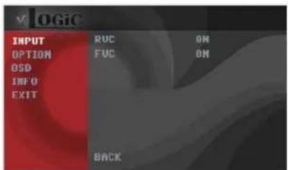

| OSD Menu | Menu item | Setting | Description |
| INPUT | FVC | OFF | No front camera connected |
| ON | Switches to front camera if parking process is enabled and reverse gear is released | ||
| OPTION | PARK LOGIC | PDC | For vehicles with PDC button. Enabled while parking process and up to 12 mph or together with PDC if existing |
| RGEAR | Enabled while parking process | ||
| RGEAR+SPEED | Enabled while parking process and up to 12 mph | ||
| RGEAR+TIME | Enabled while parking process and up to 20 second | ||
| PARK CAM | ON | OEM PDC display of the vehicle |
NOTES:
1) You can deactivate the enabled parking process by pressing the iDrive or by enabling other modes (e.g. radio). After deactivation you cannot enable the parking process again until the vehicle is driving faster than 12mph, the ignition is switched off and on OR the PDC will be disabled and enabled again, if present.
2) In case the image freezes in the Front View Camera mode, press the "Park Assist" button to go back to the radio mode.

Connection to the aftermarket rear-view camera

Connect the video RCA of the after-market rear-view camera to the female RCA connector "REAR CAM" of the interface box.

The green wire of harness Power/CAN harness can be used for +12V electric power supply (max. 1A) of the after-market rear-view camera. Configure in the OSD-menu "MISC", menu item "POWER OUT 2" the designated electric power supply (see chapter "Configurable switching outputs").
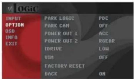
Settings for connecting an aftermarket rear-view camera
You have to configure some settings in the OSD-menus INPUTS and MISC if you want to connect an after-market rear-view camera (Operation of the OSD: see chapter "OSD-Operation").


6/11
Rev.112816
Crux Interfacing Solutions
www.cruxinterfacing.com
tel. #: (818) 609-9299
fax #: (818) 996-8188
| OSD Menu | Menu item | Setting | Description |
| INPUT | RVC | OFF | No rear-view camera connected |
| ON | Switches to rear-view camera if reverse gear is engaged and/or PDC-display is displayed | ||
| OEM | If a factory rear-view camera is existing, the interface turns off, if PDC or reverse gear is enabled and it displays factory rear-view camera and/or PDC-display | ||
| OPTION | PARK LOGIC | PDC | For vehicles with PDC button. Enabled while parking process and up to 12 mph or together with PDC if existing |
| RGEAR | Enabled while parking process | ||
| RGEAR+SPEED | Enabled while parking process and up to 12 mph | ||
| RGEAR+TIME | Enabled while parking process and up to 20 second | ||
| PARK CAM | ON | OEM PDC display of the vehicle |
Note: You can deactivate the enabled parking process by pressing the iDrive or by enabling other modes (e.g. radio). After deactivation you can't enable the parking process again until the vehicle is diving faster than 12 mph the ignition is switched off and on or the PDC will be disabled and enabled again, if present.
Dynamic Parking Guide Lines
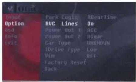
You have to configure some settings in the OSD-menu OPTION if you want to activate Dynamic Guide Lines.

natural_image
Parking lot with yellow and red painted lines on paved pavement, parked cars in background (no text or symbols)| OSD Menu | Menu item | Setting | Description |
| OPTION | RVC LINES | OFF | Dynamic Guide lines deactivated |
| ON | Dynamic Guide lines activated | ||
| iDrive Type | Low | 5 Button iDrive | |
| High | 7 Button iDrive |
Configurable Trigger Outputs

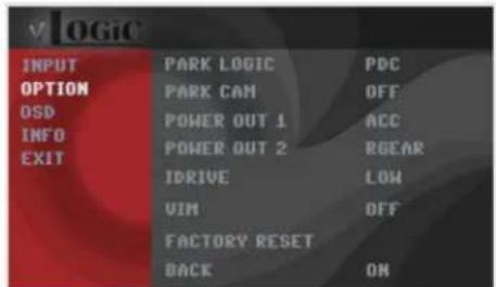
You can configure both +12V trigger outputs separately. The Pink wire is POWER OUT 1 and the Green wire is POWER OUT 2.
Note: You can configure the both trigger outputs in the OSD-Menu MISC separately (Operation of the OSD: see chapter "OSD-Operation").
| OSD Menu | Menu item | Setting | Description |
| OPTION | POWER OUT1 (pink) POWER OUT2 (green) | CAN | +12V when the interface is on (red LED on) |
| ACC | +12V when ignition is on | ||
| CAM | +12V when the rear-view camera input is activated | ||
| RGEAR | +12V when reverse gear is engaged | ||
| AVS | +12V when interface video-source is active (for external audio switch) | ||
| OFF | Trigger output deactivated |
Picture settings
You can change the picture settings in the OSD-menu IMAGE (activation only from interface AV level possible).
- Brightness
- Contrast
- Saturation
°Hue - Sharpness

Note: The picture settings will be retained for each AV-source separately.
Operation
OSD – On-Screen Display
You can change the basic configurations of the interface in the OSD (on screen display) which can be controlled with the iDrive.

8/11
Rev.112816
Crux Interfacing Solutions www.cruxinterfacing.com
tel. #: (818) 609-9299 fax #: (818) 996-8188
iDrive High

flowchart
graph TD
    A["Options"] --> B["Medium"]
    B --> C["Back"]
    C --> D["Medium"]
    D --> E["Short press=leave OSD"]
    E --> F["Options"]
    F --> G["Long press=enter OSD"]
    G --> H["Options"]
    H --> I["OK"]
    style A fill:#f9f,stroke:#333
    style B fill:#ccf,stroke:#333
    style C fill:#cfc,stroke:#333
    style D fill:#fcc,stroke:#333
    style E fill:#cff,stroke:#333
    style F fill:#ffc,stroke:#333
    style G fill:#fcc,stroke:#333
    style H fill:#ffc,stroke:#333
    style I fill:#fcc,stroke:#333
iDrive Low

flowchart
graph TD
    A["Back"] --> B["Options"]
    B --> C["OK"]
    D["Short press=leave OSD"] --> E["BACK"]
    F["Long press=enter OSD"] --> G["OPTION"]
    style A fill:#f9f,stroke:#333
    style B fill:#ccf,stroke:#333
    style C fill:#cfc,stroke:#333
    style D fill:#fcc,stroke:#333
    style E fill:#cff,stroke:#333
    style F fill:#ffc,stroke:#333
    style G fill:#fcc,stroke:#333
iDrive selection
OSD menu, "OPTION" – "IDRIVE" is for setting the right iDrive control knob.
9/11
Rev.112816
Crux Interfacing Solutions
www.cruxinterfacing.com
tel. #: (818) 609-9299
fax #: (818) 996-8188


iDrive High
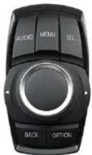
iDrive Low
| OSD-menu | Menu item | Setting | Description |
| OPTION | IDRIVE | LOW | Vehicles with iDrive Low control knob |
| HIGH | Vehicles with iDrive High control knob |
OSD – Additional setting options
The following settings in the OSD-menus OPTION and OSD can be configured over and above the described settings in this manual (Operation of the OSD: see chapter "OSD-Operation")

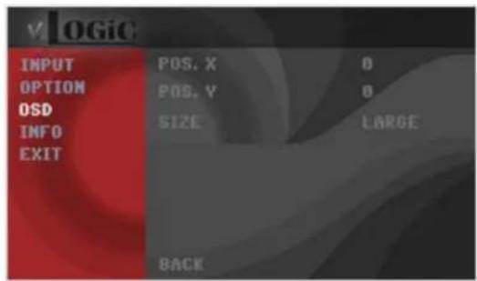
| OSD-menu | Menu item | Setting | Explication |
| OSD | POS. X | 0-xxx | Horizontal position of the OSD |
| POS. Y | 0-xxx | Vertical position of the OSD | |
| SIZE | SMALL | Small OSD menu windows | |
| LARGE | Large OSD menu windows | ||
| INFO | VERSION | X.XX.XX | Displays the current SW-version |
| OPTION | FACTORY RESET | Resetting to factory settings | |
10 / 11
Rev.112816
Crux Interfacing Solutions
www.cruxinterfacing.com
tel. #: (818) 609-9299
fax #: (818) 996-8188
Video-In-Motion function
It is possible to activate and deactivate the video-in-motion in the OSD menu "OPTION" (Operation of the OSD: see chapter "OSD-Operation").
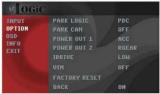
| OSD Menu | Menu item | Setting | Description |
| OPTION | VIM | ON | Video-in-motion activated |
| OFF | Video-in-motion deactivated |
Selecting the interface as current video-source


A long press of the MEDIA button OR the AUDIO button, respectively, is used to choose the interface as current video source.
A short press of the MEDIA button OR the AUDIO button will switch the video sources. Each short press will switch to the next enabled input. If all inputs are enabled the order is:
Rear Cam → Front Cam →...
Inputs which are not enabled are skipped.
NOTE: A short press of either the BACK / RADIO / MENU / TEL / NAV button will exit to the factory screen.
11/11
Rev.112816
Crux Interfacing Solutions
www.cruxinterfacing.com
tel. #: (818) 609-9299
fax #: (818) 996-8188


- Vehicle Applications
- BMW
- Product Features
- Navigation / Radio Compatibility
- Notes
- Parts Included
- Wiring Diagram
- Installation Instructions
- Setting the DIP switches of the Interface Box.
- Settings for connecting an aftermarket front camera
- NOTES:
- Connection to the aftermarket rear-view camera
- Settings for connecting an aftermarket rear-view camera
- Dynamic Parking Guide Lines
- Configurable Trigger Outputs
- Picture settings
- Operation
- OSD – On-Screen Display
- iDrive selection
- OSD – Additional setting options
- Video-In-Motion function
- Selecting the interface as current video-source
Brand : CRUX
Model : VRFBM-77i
Category : Unspecified