
PRM-503A - Tracking Postium - Free user manual and instructions
Find the device manual for free PRM-503A Postium in PDF.


| Product Type | Tracking Device |
| Brand | Postium |
| Model | PRM-503A |
| Dimensions | 80 mm x 50 mm x 20 mm |
| Weight | 50 g |
| Power Supply | Rechargeable Lithium-ion Battery, 3.7V 500mAh |
| Connectivity | Bluetooth 4.0, GPS, GSM |
| Tracking Technology | GPS + AGPS |
| Real-time Tracking | Yes, via mobile app |
| Geofencing | Configurable safe zones with alerts |
| History Playback | Up to 90 days of location history |
| Alerts | Movement, geofence, low battery, SOS |
| Water Resistance | IP65 rating (dust and water jets) |
| Operating Temperature | -10°C to 50°C |
| Battery Life | Up to 7 days in standard mode |
| Charging Time | Approximately 2 hours |
| Compatible Systems | iOS 9.0+, Android 5.0+ |
| Included Accessories | USB charging cable, mounting bracket, quick start guide |
| Maintenance | Clean with a soft dry cloth; avoid solvents |
| Safety | Keep away from water immersion; do not disassemble |
| Spare Parts Availability | Battery and charging cable available from manufacturer |
| Warranty | 1 year limited warranty |
Frequently Asked Questions - PRM-503A Postium
User questions about PRM-503A Postium
0 question about this device. Answer the ones you know or ask your own.
Ask a new question about this device
Download the instructions for your Tracking in PDF format for free! Find your manual PRM-503A - Postium and take your electronic device back in hand. On this page are published all the documents necessary for the use of your device. PRM-503A by Postium.
USER MANUAL PRM-503A Postium
natural_image
Front panel of a black electronic device displaying three video screens: air, airplane, and motorcycle, with no visible text or symbols on the devices themselves.PRM-503A
MULTI-CHANNEL LCD MONITOR
User's Manual

Contents
PRM-503A
Warnings 3
Features 4
Name & Function of Each Part .... 5
OSD Menu Organization & Adjustment 7
Other Functions 15
Special Functions 25
System Default Value.... 26
Product Specification 27
Warning
· Always use set voltage.
- DC 12V
- If liquid is spilled on or impacts this product, please disconnect the product immediately and seek professional help before continued use.
- Keep unit disconnected during extended periods of disuse.
- Keep unit in a well-ventilated place to prevent overheating.
- Do not install the product near any heat-generating equipment.
Also, keep the product out of direct sunlight or dusty areas.
- Only clean the product with a noncommercial, mild and neutral detergent.
- When transporting the product, make use of its original packaging for safer carriage.
FCC (Federal Communications Commission)
This equipment has been tested and found to comply with the limits for class A digital device, pursuant to part 15 of the FCC Rules. These limits are designed to provide reasonable protection against harmful interface when the equipment is operated in a commercial environment.
This equipment generates, uses, and can radiate radio frequency energy, and if not installed and used in accordance with the instruction manual, may cause harmful interference to radio communications. Operation of this equipment in a residential to correct the interference at his own expense
Warning!! : Change or modifications not expressly approved by the manufacturer responsible for compliance void the user's authority to operate the equipment.
Disposal of Old Electrical & Electronic Equipment (Applicable in the European Union and other European countries with separate collection systems)

This symbol on the product or on its packing indicates that this product shall not be treated as household waste. Instead it shall be handed over to the applicable collection point for the recycling of electrical and electronic equipment. By ensuring this product is disposed of correctly, you will help prevent potential negative consequence for the environment and human health, which could otherwise be caused by inappropriate waste handling of this product. The recycling of materials will help to conserve natural resources.
Features
Multi-Format PRM-503A Series unit has the following features:
- Compatible with varied SDI Signals
The product is compatible with varied SDI signal
-480i,576i,720p,1035i,1080i,1080p,1080psf, 2K
- Compatible with varied Composite Signals
- NTSC, PAL, SECAM
· Waveform/Vector Scope/Audio Level Meter
Waveform & Vector Scope available for SDI Signals
Embedded Audio Level Meter
· BLUE ONLY/MONO
· H/V delay
· Wide Variety of Markers & Safety Areas
Center Marker, Safety Area Marker, Aspect Marker, Display Size(Scan)
- Pixel To Pixel
Provides both full screen and unscaled native image.
· Wide Screen/LED Backlight
· 24Bit RGB Interface Panel
· DC Compatible
The product is powered by normal 12V source.
- Remote control function
Simple remote controllability with single cable connection, no additional modules required
· Additional Features
Active Loop Through/SDI, 600:1 contrast ratio, 300 cd/m2 brightness, OSD user interface, Rack Mountable
Name & Function of Each Part

· [INPUT] button
Used to select SDI A / SDI B / COMPOSITE Input (Rotation)
- [MENU] button
Used to activate the OSD menu.
· [UP] button
Used to navigate menu during OSD menu activation. It may also be used to toggle clockwise through 1:1 quadrants in native scan mode
· [DOWN] button
Used to navigate menu during OSD menu activation. It may also be used to toggle counterclockwise through 1:1 quadrants in native scan mode
· [ENTER] button
Used to confirm a chosen value (or mode) within the OSD menu.
This can be used to control the position of Waveform in small size.
· [POWER] button
Power On/Off button.
If the signal is normal, LED lights in Green. If the signal is unsupported or disconnected, LED lights in Yellow.
· TALLY
LED indicating monitor's current status using optional Remote.

· REMOTE (RJ-45)
Connection for remote control of monitor.
· SDI A-IN (BNC)
SDI A signal input terminal
· SDI B-IN (BNC)
SDI B signal input terminal
· SDI-OUT (BNC)
SDI signal output terminal
· COMPISITE INPUT (BNC)
COMPOSITE signal input terminal
· COMPOSITE OUTPUT (BNC)
COMPOSITE signal output terminal
· FACTORY PGM (15 pins)
Input connector for FACTORY PGM allowing for firmware updates.
· DC IN (XLR, 4 pins)
Used to supply DC power; 12V

OSD Menu Organization & Adjustment
[1] MAIN - Picture
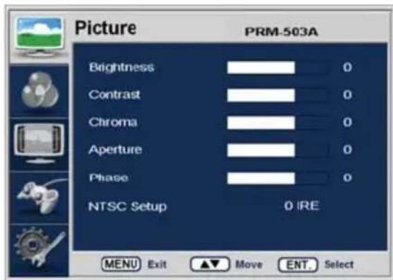
· Brightness
This Item controls the degree of brightness.
- Contrast
This item controls the contrast ratio.
- Chroma
This item controls saturation.
· Aperture
This item controls the picture sharpness.
- Phase
This item controls Phase value (Hue).
This function is only available in Composite Input.
- NTSC Setup
This item sets IRE value in NTSC mode between 0 IRE and 7.5 IRE.
This function is only available in Composite NTSC Input.
[2] MAIN - Color

- Color Temp
This item controls Color Temperature with presets of 3200K, 5600K, 6500K, 9300K and User1, User2, User3 mode.
- User
On User Mode, the user may select and control R, G, & B GAIN, BIAS values by using the [UP]/[DOWN]/[ENTER] buttons.
- Color Copy
In User Mode, user can copy the preset of 3200K, 5600K, 6500K or 9300K to make the custom adjustment by using the Up/Down/Enter buttons.
[3] MAIN - Marker

- Marker
Used to show MARKER on the screen. The type of marker at work may be selected on the other menu.
This feature disables when the H/V Delay or Pixel to Pixel mode is activated.
· Line Marker
This selects the marker type when the Line Marker is displayed on the screen.
Compatible Line MARKER types are as follows:
| MODE | Line Marker CLASS |
| HD | 16:9, 4:3, 4:3 ON AIR, 15:9, 14:9, |
| SD 16:9 | 13:9, 1.85:1, 2.35:1, 1.85:1 & 4:3 |
| SD 4:3 | 16:9 |
- Center Marker
This item displays the Center Marker on the screen.
· Safety Area
This item controls the size of the Safety Area between 80%, 85%, 88%, 90%, 93% and 100%.
- Marker Mat
This item darkens the area outside of Line Marker setting area. The degree of the matte is between OFF(0) and (7).
The higher the number the darker Line Marker the matte becomes.
- Marker Color
This item controls Marker color. Selectable colors are white, gray, black, red, green and blue.
# Line Marker, Center Marker and Safety Area functions are operates only after activating the MARKER function by setting to 'On' the Marker menu.
[4] MAIN - Remote
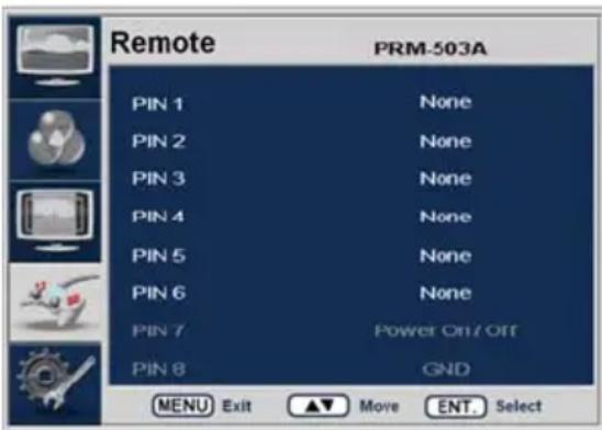
REMOTE (RJ-45)
1: Pin1
2: Pin2
3: Pin3
4: Pin4
5: Pin5
6: Pin6
7: Pin7
8: GND

· Pin1 \~ Pin6
The user may connect RJ-45 jack to the remote terminal on the rear of the unit and designate a function for each pin.
The selectable functions are as follows:
| Menu Classification | Settable Values |
| PIN 1~6 | ANALOG CHANNEL, DIGITAL A CHANNEL, DIGITAL B CHANNE TALLY RED, TALLY GREENBLUE ONLYUNDERSCANASPECTHVDELAY16:9 MARKER, 15:9 MARKER, 14:9 MARKER,13:9 MARKER, 4:3 MARKER, 4:3 ON AIR MARKER,1.85:1 MARKER, 2.35:1 MARKER, 1.85:1 & 4:3 MARKERCENTER MARKERSAFETY AREA 80%, SAFETY AREA 85%, SAFETY AREA 88%,SAFETY AREA 90%, SAFETY AREA 93%, SAFETY AREA 100% |
· Pin7
PIN7 is for POWER ON/OFF use only.
[5] MAIN - System [page1]
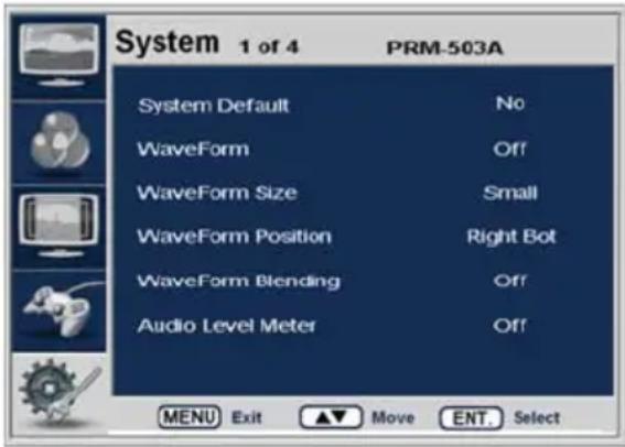
- System Default
User can use the System Default menu to initialize the values of the monitor.
· WaveForm
This item controls the Waveform or Vector Scope.
- WaveForm Size
This item controls the size of Waveform or Vector Scope.
- WaveForm Position
This item controls the position of Waveform or Vector Scope between Right, Center and Left.
In normal display, press Enter button to activate this feature.
This feature can be activated in small size mode only.
· WaveForm Blending
This item activates the blending of Waveform or Vector Scope.
This feature activates automatically if WaveForm overlaps with OSD.
This feature can be activated in small size mode only.
· Audio Level Meter
This item set embedded audio group selects Off, G1+G2, G2+G3, G3+G4, G1+G3, G1+G4, G2+G4 to activate Audio Level Meter.
Menus or features which are related with WaveForm enables in SDI input mode only.
[6] MAIN - System [page2]

- Source ID
This item is used to activate the Source ID display by selecting BG Type or Char Type.
- Source ID Character
This item is used to customize the Source ID display. (A\~Z, a\~z, 0\~9 and special characters)
- Source ID Position
This item controls the position of Source ID display. (Top-left, Top-center, Top-right, Bottom-right, Bottom-center, Bottom-left)
- Source ID Color
This item is used to change the color of Source ID display by selecting black, white, red, green, blue or yellow.
· Time Code
This item activates the Time Code. Select between VITC or LTC.
- Internal Pattern
This item is used to activate the internal Pattern of 100% White or 100% Color Bar.
[7] MAIN - System [page3]
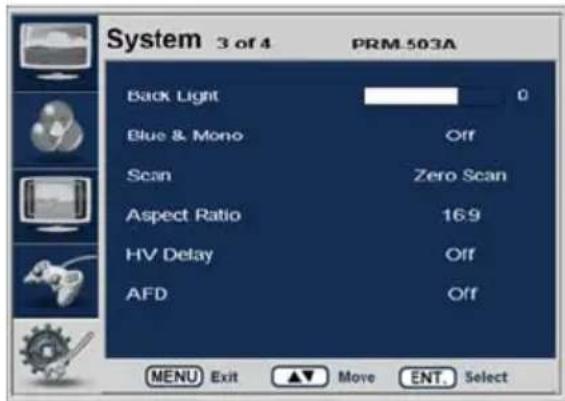
· Back Light
This item controls the LED backlight setting. The value should be within range between MIN(0) and MAX(25).
· Blue & Mono
You may remove R(red) and G(green) from the input signal and play the screen only with B(blue) signal. Menu may be set to 'Mono' to change the screen to MONO mode.
(This mode uses only Luminance value.)
- Scan
This item controls to transfer from ZERO SCAN mode to Pixel To Pixel mode.
Mode changes in the order of Zero Scan -> Over Scan -> Pixel To Pixel -> Zero Scan.
In Pixel to Pixel mode, Marker feature and menu disable automatically.
In Pixel to Pixel mode, pressing Enter button rotates the position of display.
PRM-503A MULTI-CHANNEL LCD MONITOR
- Aspect Ratio
This item toggles aspect ratio in SD from standard to anamorphic.
SD signal only (Disables automatically in any other signal including No signal)
· HV Delay
This item activates the HV Delay mode.
In HV Delay mode, Marker feature and menu disable automatically.
· AFD
This item activates the AFD mode. Selectable mode are Off, Aspect Mode and Marker Mode.
This feature action in only SDI signal included AFD Data.
In Internal Pattern mode, this feature and menu disable automatically.
- Activating Internal Pattern disables Scan, Aspect Ratio and HV Delay.
[8] MAIN - System [page4]
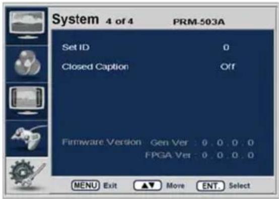
- Set ID
This item controls the Set ID setting for UMD. The value should be within range between 0 and 99.
- Closed Caption
This item controls colsed caption ON/OFF. (708, 608(Line21), 608(ANC))
- Firmware Version
This item is the firmware version of the system.
- License
[9] INPUT Menu
flowchart
graph TD
    A["SDI A\n1920 X 1080 60I"] --> B["SDI B\n1920 X 1080 60I"]
    B --> C["COMPOSITE\n720 X 480 60I"]

natural_image
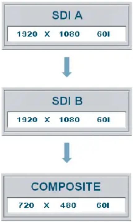
Simple blue vertical line with a curved arrowhead on the left (no text or symbols)- PRM-503A Series unit is capable of processing varied Input signals Composite and SDI.
- Press [INPUT] button on the front of the monitor and activate the OSD menu as shown on the left.
Select the input you desire by using the [INPUT] Button.
- User can change and select the input mode by using this one simple button.
# If no image displays after selecting the desired input mode, check and make sure that your connection is not lose or disconnected.
# Input resolution displays on the bottom of the OSD screen.
Other Functions
[1] PIXEL TO PIXEL
- PRM-503A monitor's Pixel to Pixel mode displays input signal without scaling.
- To activate the [Pixel to Pixel] mode, access the Scan menu in Syetem menu and select [Pixel to Pixel].
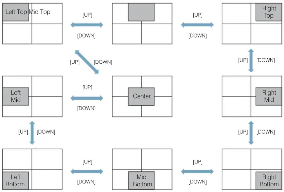
- In the [Pixel To Pixel] mode, use the [UP]/[DOWN] buttons to toggle between 1:1 scan sections
| Input | Action Button | Available Modes |
| HD 1080i/1080p | [UP](Clockwise) | Center -> Left Top ->Mid Top -> Right Top -> Right Mid -> Right Bottom -> Mid Bottom -> Left Bottom -> Left Mid -> Center -> .... |
| [DOWN](Opposite) | Center -> Left Mid -> Left Bottom -> Mid Bottom -> Right Bottom -> Right Mid -> Right Top -> Mid Top -> Left Top -> Center -> ... |
- OSD change
![Postium PRM-503A - [1] PIXEL TO PIXEL - 1](/content/2026/06/1249388/images/c0f29f84bb278ffa1b8a858a94c1c6fecdf269af42ed55f09a16e949010029a8.jpg)
flowchart
graph TD
    A["Left Top"] -->|[UP]| B["Mid Top"]
    B -->|[UP]| C["Right Top"]
    D["Left Mid"] -->|[UP]| E["Center"]
    F["Left Bot"] -->|[UP]| G["Mid Bot"]
    H["Right Bot"] -->|[UP]| I["Right Mid"]
    style A fill:#f9f,stroke:#333
    style B fill:#f9f,stroke:#333
    style C fill:#f9f,stroke:#333
    style D fill:#f9f,stroke:#333
    style E fill:#f9f,stroke:#333
    style F fill:#f9f,stroke:#333
    style G fill:#f9f,stroke:#333
    style H fill:#f9f,stroke:#333
    style I fill:#f9f,stroke:#333
| Input | Action Button | Available Modes |
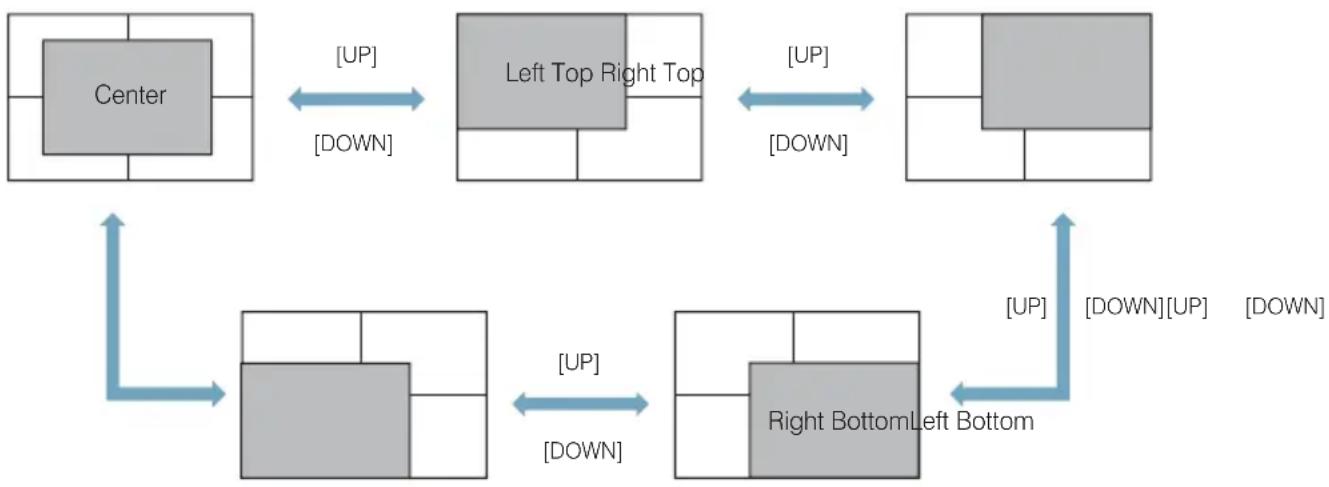
| HD 720p | [UP](Clockwise) | Center -> Left Top -> Right Top -> Right Bottom -> left Bottom -> Center -> ... |
| [DOWN](Opposite) | Center -> Left Bottom -> Right Bottom -> Right Top -> Left Top -> Center -> .... | |
- OSD change![Postium PRM-503A - [1] PIXEL TO PIXEL - 2](/content/2026/06/1249388/images/fea613332b80eb6b5acec543f0943364e633b66fa0f7f42e66839f15127bbe79.jpg) | ||
Pixel To Pixel mode is not available in Graphic mode.
Pixel To Pixel mode is available in SD mode, but 1:1 sections cannot be rotated through as with HD sources.
- Positions in HD Signal 1080i/1080p mode
flowchart
graph TD
    A["Left Top Mid Top"] -->|[UP]| B["Center"]
    B -->|[UP]| C["Right Top"]
    A -->|[DOWN]| B
    B -->|[DOWN]| C
    D["Left Mid"] -->|[UP]| E["Center"]
    E -->|[UP]| F["Right Mid"]
    D -->|[DOWN]| E
    E -->|[DOWN]| G["Right Bottom"]
    H["Left Bottom"] -->|[UP]| I["Center"]
    I -->|[UP]| J["Right Bottom"]
    H -->|[DOWN]| I
    I -->|[DOWN]| J
- Position in HD Signal 720p mode
flowchart
graph TD
    A["Center"] -->|[UP]/[DOWN]| B["Left Top Right Top"]
    B -->|[UP]/[DOWN]| C["Right BottomLeft Bottom"]
    C -->|[UP]/[DOWN]/[UP]| D["Right BottomLeft Bottom"]
    D -->|[UP]/[DOWN]/[UP]| E["Right BottomLeft Bottom"]
    E -->|[UP]/[DOWN]/[UP]| F["Right BottomLeft Bottom"]
[2] Waveform
Small display : YCbCr → Y → Cb → Cr → Vector → off
Full display : Y → Cb → Cr → Vector → off
· Waveform
| OFF Waveform | |
![Postium PRM-503A - [2] Waveform - 1](/content/2026/06/1249388/images/4e518eb69fb28029b82afbb2e9adb18f1eb2ffece67e3af97f0dca0b2e51e56e.jpg) | ![Postium PRM-503A - [2] Waveform - 2](/content/2026/06/1249388/images/c312476adf7225c0c89e03d18761fcdac6d774e216affe7bbd5117f9896aa434.jpg) |
· Waveform Size
| Small (Y) Small (Cb, Cr, Y) Full (Y) | ||
![Postium PRM-503A - [2] Waveform - 3](/content/2026/06/1249388/images/38db80e76c408a6b9b363bfa7eceda67b96521000a1c3b4b746c20cb3d59cc6f.jpg) | ![Postium PRM-503A - [2] Waveform - 4](/content/2026/06/1249388/images/1ac11ad067cc332ca4c0920fc007ab461df153e9a7581708bc8721ad892a4d1d.jpg) | ![Postium PRM-503A - [2] Waveform - 5](/content/2026/06/1249388/images/4d02217c946b3119b3afc95a58d26eca3e9ff1e6eae4563006525f81f5181651.jpg) |
If push the Input button (SDI-A, SDI-B and Analog), Waveform full mode is change to small mode automatically.
· Waveform Positions
| Left Center Right | ||
![Postium PRM-503A - [2] Waveform - 6](/content/2026/06/1249388/images/93b76fa7037d7a620da444bfb6ae33c2ad48751b525576b9baab8172bb38369f.jpg) | ![Postium PRM-503A - [2] Waveform - 7](/content/2026/06/1249388/images/c4aecddc1c16161cd19477562afc5a490a6d23f464ac0973a9ef9890369138e1.jpg) | ![Postium PRM-503A - [2] Waveform - 8](/content/2026/06/1249388/images/d88438efddf7ae77e769c17fc505abd7c0397533c248bf203330b5f88a6d48da.jpg) |
· Waveform Blending
| OFF ON | |
![Postium PRM-503A - [2] Waveform - 9](/content/2026/06/1249388/images/8fd7bde01e4eca1c8daf3d5218bc2a57abbfa262ee71e6bb3da310a8e33f3b5a.jpg) | ![Postium PRM-503A - [2] Waveform - 10](/content/2026/06/1249388/images/cfdebb381d00997b52ddb1bb4e1a40e0e365446a860b6b3c880bbbd9bd0926b4.jpg) |
- Exception: If overlaps with OSD, blending activates automatically.
| Main OSD Info Window | |
![Postium PRM-503A - [2] Waveform - 11](/content/2026/06/1249388/images/67f21a966b72387245607d6c42e24c13c0e953e8add4de02b367bb8c2a8432c5.jpg) | ![Postium PRM-503A - [2] Waveform - 12](/content/2026/06/1249388/images/8917d2f75e04230b159b75d1aa813e1d9b26244fa6d943592f033d5a1aa627d8.jpg) |
| Pixel To Pixel Source ID | |
![Postium PRM-503A - [2] Waveform - 13](/content/2026/06/1249388/images/0318953ed126e7c1ff30e40554390991a80ccef2cc7f46544491e6c9a8976fda.jpg) | ![Postium PRM-503A - [2] Waveform - 14](/content/2026/06/1249388/images/ab22ce7cf423d90f5e59ffd665c091a178cda08269a0dfa41e5726c539486e84.jpg) |
This function is only available with SDI Input.
[3] Vector Scope
- Vector Scope
| Vector Scope OFF Vector Scope ON | |
![Postium PRM-503A - [2] Waveform - 15](/content/2026/06/1249388/images/4c7aab7555174e6dee8a3f55b45df8f5ccbf279e7940d12062be70add0f9536e.jpg) | ![Postium PRM-503A - [2] Waveform - 16](/content/2026/06/1249388/images/5c4ebb9a35e1cbc272739c172591502c89a57a5151cbddb0a7630eb18a963e79.jpg) |
- Vector Scope Size
| Small Full | |
![Postium PRM-503A - [2] Waveform - 17](/content/2026/06/1249388/images/0f6c69cb8077d5324839d82d45958a7598ac477ed9cb098a694c9ef4dd035bb9.jpg) | ![Postium PRM-503A - [2] Waveform - 18](/content/2026/06/1249388/images/6a54b2ebc8cbbf37ee2045022fe1e23839187bab82779d7b3bfa031e6dae3898.jpg) |
Vector Scope Position / Blending
: Refer to the Waveform position (P.18) and Waveform Blending (P.19)
This function is only available with SDI Input.
[4] Audio Level Meter
- Audio Level Meter
| OFF HORIZONTAL VERTICAL | ||
![Postium PRM-503A - [4] Audio Level Meter - 1](/content/2026/06/1249388/images/1e2548b74d1176b2d4ec84df97d5a0405cd65f1821700664bd51365c9e6bd5b8.jpg) | ![Postium PRM-503A - [4] Audio Level Meter - 2](/content/2026/06/1249388/images/df1649633b05041ca1fc30dc4aed60994b41d90558f30e67dfce33f33bfa5730.jpg) | ![Postium PRM-503A - [4] Audio Level Meter - 3](/content/2026/06/1249388/images/e39c116e78492aa1333e36a2359eb4dd50bcdd6ff82cac3ef1affeef0d416f6e.jpg) |
| dBFS BBC EBU | ||
![Postium PRM-503A - [4] Audio Level Meter - 4](/content/2026/06/1249388/images/de94f5aa0bd8429fdf90ca1053f77b531492b975491d0860f2084818f50ab3bf.jpg) | ![Postium PRM-503A - [4] Audio Level Meter - 5](/content/2026/06/1249388/images/178fa0e4211d33209e671b082fce61f92d57da26730be795eb91009f98ca3011.jpg) | ![Postium PRM-503A - [4] Audio Level Meter - 6](/content/2026/06/1249388/images/50d48a983677e59af18f32ee0ad67ce0c83cf03862eed251ca817079b085fecb.jpg) |
| VU Nordic | ||
![Postium PRM-503A - [4] Audio Level Meter - 7](/content/2026/06/1249388/images/6cafe495825f168b6fdb56c6045e00a320f217c35d205f64f3bf5f972f9a8a59.jpg) | ![Postium PRM-503A - [4] Audio Level Meter - 8](/content/2026/06/1249388/images/3703e46599ad995220e5e41668c2e50a7838ff8301f786f232f5046af83f87e1.jpg) | |
![Postium PRM-503A - [4] Audio Level Meter - 9](/content/2026/06/1249388/images/38a08ec6f4d2fada7b7e339df6cf9490ecf40011420dfe24389e8da938be1360.jpg)
bar_stacked
| Sample | On signal, Blue bar | Alignment | Permitted Max | | :--- | :--- | :--- | :--- | | 1 | -25.0 | 10.0 | -11.0 | | 2 | -25.0 | 10.0 | -10.4 | | 3 | -25.0 | 10.0 | -7.4 | | 4 | -25.0 | 10.0 | -25.0 | | 5 | -25.0 | 10.0 | -3.0 | | 6 | -25.0 | 10.0 | -10.0 | | 7 | -25.0 | 10.0 | -10.0 | | 8 | -25.0 | 10.0 | -25.0 | | 9 | -25.0 | 10.0 | -10.0 | | 10 | -25.0 | 10.0 | -10.0 | | 11 | -25.0 | 10.0 | -10.0 | | 12 | -25.0 | 10.0 | -10.0 | | 13 | -25.0 | 10.0 | -10.0 | | 14 | -25.0 | 10.0 | -10.0 | | 15 | -25.0 | 10.0 | -10.0 | | 16 | -25.0 | 10.0 | -10.0 |- Avoid Overlap
In full size WaveForm mode, WaveForm shifts down to avoid the overlap with Audio Level Meter.
| Audio Level Meter OFF Audio Level | Meter ON |
 |  |
· Group & Channel
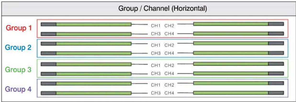
This function is only available with SDI Input.

flowchart
graph TD
    A["Group / Channel (Vertical)"] --> B["Group 1"]
    A --> C["Group 2"]
    A --> D["Group 3"]
    A --> E["Group 4"]
    B --> F["CH1 CH3"]
    C --> G["CH1 CH3"]
    D --> H["CH1 CH3"]
    E --> I["CH4 CH2 CH4 CH2 CH4 CH2 CH4 CH2"]
    F --> J["Stacked Bar"]
    G --> K["Stacked Bar"]
    H --> L["Stacked Bar"]
    I --> M["Stacked Bar"]
[5] Time Code
| Time Code | Time Code + Audio Level Meter |
| Time Code + WaveForm Full Size Time Code + SourceID + WaveForm + Audio Level Meter | |
This function is only available with SDI Input.
[6] Source ID
- Source ID
| BG Type Char Type | |
- Source ID Position

- Source ID Color
| Black | White | Red | Green | Blue | Yellow |
| CAM-1 | CAM-1 | CAM-1 | CAM-1 | CAM-1 | CAM-1 |
[7] MAIN - System [page3]
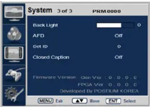
· Back Light
This item controls the LED backlight setting. The value should be within range between MIN(0) and MAX(50).
· AFD
This item activates the AFD mode. Selectable mode are Off, Aspect Mode and Marker mode. This feature action in only SDI signal included AFD Data. In Internal Pattern mode, this feature and menu disable automatically.
- Set ID
This item controls the Set ID setting for UMD. The value should be within range between 0 and 99.
· Closed Caption
This item controls closed caption ON/OFF.(708, 608(Line21), 608(ANC))
- Firmware Version
This item is the firmware version of the system.
· License
Special Functions
[1] HD Signal Activate (SD Version only)
This function activate SD/HD mode for SD only version.
You have to enter DOWN key for 5 seconds or more than in normal condition such as without any window,
| Display Description | |
| HD Signal ActivateSerial Number:XXXXXXXX Activation: None (SD Only)MENU: Exit / ENTER: Enter Code | · Default Window- MENU: Close Window- ENTER: Move to Window for Enter Code |
| HD Signal ActivateSerial Number:XXXXXXXX Enter Code:XXXX-XXXX OKUP/DOWN: Select / ENTER: Move | · Enter Code Window(Enter 8 codes in order left to right.)- MENU: Close Window- ENTER: Move Cursor to Right- UP/DOWN: Change Code (0,2,3,5~7, A~Z) |
| HD Signal ActivateSerial Number:XXXXXXXX Enter Code:XXXX-XXXX OKMENU: Exit / ENTER: Submit | · Enter Code Window(Go submit after enter the code.)- MENU: Close Window- ENTER: Submit |
| HD Signal ActivateActivate Success!!System will reboot... | · Result Window(Display a activate result.)- MENU: Close Window & System reboot- If you don't enter any key, System will reboot later 3 seconds automatically. |
| HD Signal ActivateSerial Number:XXXXXXXX Activation:Success (SD/HD)MENU: Exit / ENTER: Enter Code | · You can see the activate result on Default window go back. (Success or None) |
System Default Value
| MEMU | Value | |
| Picture | Brightness | 0 |
| Contrast | 0 | |
| Chroma | 0 | |
| Aperture | 0 | |
| Phase | 0 | |
| NTSC Setup | 7.5 IRE | |
| Color | Color Temp | 6500K |
| Gain Red (1/2/3) | 0 | |
| Gain Green (1/2/3) | 0 | |
| Gain Blue (1/2/3) | 0 | |
| Bias Red (1/2/3) | 0 | |
| Bias Green (1/2/3) | 0 | |
| Bias Blue (1/2/3) | 0 | |
| Color Copy | 6500K | |
| Marker | Marker | Off |
| Line Marker | Off | |
| Center Marker | Off | |
| Safety Area | Off | |
| Maker Mat | Off | |
| Marker Color | White | |
| Remote | PIN 1 | Analog Channel |
| PIN 2 | Digital A Channel | |
| PIN 3 | Digital B Channel | |
| PIN 4 | Tally R | |
| PIN 5 | Tally G | |
| PIN 6 | Blue Only | |
| System [Page1] | System Default | No |
| WaveForm | Off | |
| WaveForm Size | Small | |
| WaveForm Position | Right Bot | |
| WaveForm Blending | Off | |
| Audio Level Meter | Off | |
| System [Page2] | Source ID | Off |
| Source ID Character | C A M - 1 | |
| Source ID Position | Left Top | |
| Source ID Color | Black | |
| Time Code | Off | |
| Internal Pattern | Off | |
| System [Page3] | Back Light | 20 |
| Blue & Mono | Off | |
| Scan | Zero Scan | |
| Aspect Ratio | 16:9 | |
| HV Delay | Off | |
| AFD | Off | |
| System [Page4] | Set ID | 0 |
| Closed Caption | Off | |
Product Specification
| Input (1 Screen) | 1 x BNC | Composite Input |
| 2 x BNC | SDI Input | |
| Output (1 Screen) | 1 x BNC | Composite Output (Internal Buffer Output) |
| 1 x BNC | SDI Output (Active Through Out) | |
| Input Signal | Analog | Composite (1.0Vpp with Sync) |
| HD-SDI | 1.485 Gbps | |
| SD-SDI | 270 Mbps | |
| SDI Input Signal Formats | SMPTE-274 | 1080i (60/59.94/50) |
| 1080P (30/29.97/25/24/24sF/23.98/23.98sF) | ||
| SMPTE-296M | 720P (23.98/24/25/29.97/30/50/59.94/60) | |
| SMPTE-260M | 1035i (60/59.94) | |
| SMPTE-125M | 480i (59.94) | |
| ITU-R.BT.656 | 576i (50) | |
| 2K Format | 2048 x 1080 (23.98psf/24psf/23.98p/24p) | |
| LCD | Size | 5.0 inch |
| Resolution | 800 x 480 (15:9) | |
| Pixel Pitch | 0.135(H) x 0.135(V) mm | |
| Color | 16.7M (True), 24bit | |
| Viewing Angle | H: 170 degrees | |
| V: 170 degrees | ||
| Luminance of White | 300cd/m2 (center) | |
| Contrast | 600: 1 | |
| Display Area | 108.0 x 64.8 mm | |
| Power | 12V DC | |
| Power Consumption (Approx.) | Watts | |
| Operating Temperature | 0°C to 40°C (32°F to 104°F) | |
| Storage Temperature | -30°C to 50°C (-22°F to 122°F) | |
| Main Body Dimensions (mm/inch) | 480 x 87 x 68mm / 18.89 x 3.42 x 2.67 inch | |
| Weight | 2.5kg(5.5 lbs) | |
| Accessory | DC Power Adapter | |
| Option | 19" Rack Mountable Kit (2U) (Triple Monitor) | |
* Above specifications may be changed without notice
PRM-503A MULTI-CHANNEL LCD MONITOR

POSTIUM KOREA
Co., Ltd.
208, Building A, Samsong Techno Valley, 140, Tongil-ro,
Deogyang-gu, Goyang-si, Gyeonggi-do, Korea, 10594
Tel : +82.2.354.6055 / Fax : +82.2.354.6056
E-mail:sales@postium.com/ www.postium.com


- PRM-503A
- Contents
- Warning
- FCC (Federal Communications Commission)
- Disposal of Old Electrical & Electronic Equipment (Applicable in the European Union and other European countries with separate collection systems)
- Features
- Multi-Format PRM-503A Series unit has the following features:
- Name & Function of Each Part
- OSD Menu Organization & Adjustment
- · Brightness
- - Contrast
- - Chroma
- · Aperture
- - Phase
- This function is only available in Composite Input.
- - NTSC Setup
- This function is only available in Composite NTSC Input.
- - Color Temp
- - User
- - Color Copy
- - Marker
- This feature disables when the H/V Delay or Pixel to Pixel mode is activated.
- · Line Marker
- - Center Marker
- · Safety Area
- - Marker Mat
- - Marker Color
- REMOTE (RJ-45)
- - WaveForm Size
- - WaveForm Position
- In normal display, press Enter button to activate this feature.
- This feature can be activated in small size mode only.
- · WaveForm Blending
- This feature activates automatically if WaveForm overlaps with OSD.
- · Audio Level Meter
- Menus or features which are related with WaveForm enables in SDI input mode only.
- - Source ID
- - Source ID Character
- - Source ID Position
- - Source ID Color
- · Time Code
- - Internal Pattern
- · Back Light
- · Blue & Mono
- - Scan
- In Pixel to Pixel mode, Marker feature and menu disable automatically.
- In Pixel to Pixel mode, pressing Enter button rotates the position of display.
- PRM-503A MULTI-CHANNEL LCD MONITOR
- - Aspect Ratio
- SD signal only (Disables automatically in any other signal including No signal)
- · HV Delay
- In HV Delay mode, Marker feature and menu disable automatically.
- · AFD
- This feature action in only SDI signal included AFD Data.
- In Internal Pattern mode, this feature and menu disable automatically.
- - Set ID
- - Closed Caption
- - Firmware Version
- - License
- Other Functions
- [1] PIXEL TO PIXEL
- Pixel To Pixel mode is not available in Graphic mode.
- Pixel To Pixel mode is available in SD mode, but 1:1 sections cannot be rotated through as with HD sources.
- [2] Waveform
- [4] Audio Level Meter
- - Avoid Overlap
- · Group & Channel
- This function is only available with SDI Input.
- · Closed Caption
- · License
- Special Functions
- [1] HD Signal Activate (SD Version only)
Brand : Postium
Model : PRM-503A
Category : Tracking