
GT2150 - Video projector NEC - Free user manual and instructions
Find the device manual for free GT2150 NEC in PDF.


| Product Type | LCD Video Projector |
| Brand | NEC |
| Model | GT2150 |
| Native Resolution | XGA (1024 x 768) |
| Brightness | 3500 lumens ANSI |
| Contrast Ratio | 500:1 |
| Aspect Ratio | 4:3 (native) |
| Lamp Type | UHP 200W Lamp |
| Lamp Life | Approximately 3000 hours (normal mode) |
| Dimensions (W x H x D) | 358 x 326 x 147 mm |
| Weight | 6.2 kg |
| Power Supply | 100-240 V AC, 50/60 Hz |
| Power Consumption | 350 W (max) |
| Connectivity | VGA, S-Video, Composite, Audio input/output |
| Main Features | Keystone correction, digital zoom, auto standby |
| Maintenance and Cleaning | Clean the air filter every 500 hours; replaceable lamp |
| Safety | Kensington lock, auto shutdown on overheating |
| Spare Parts and Repairability | Lamp, air filter, remote control available as options |
| General Information | User manual available for free download |
Frequently Asked Questions - GT2150 NEC
User questions about GT2150 NEC
0 question about this device. Answer the ones you know or ask your own.
Ask a new question about this device
Download the instructions for your Video projector in PDF format for free! Find your manual GT2150 - NEC and take your electronic device back in hand. On this page are published all the documents necessary for the use of your device. GT2150 by NEC.
USER MANUAL GT2150 NEC
Please read this manual carefully before using your NEC GT2150 Projector and keep the manual handy for future reference.
Your serial number is located on the bottom of your GT2150. Record it here:
CAUTION

To turn off main power, be sure to remove the plug from power outlet.
The power outlet socket should be installed as near to the equipment as possible, and should be easily accessible.
CAUTION

TO PREVENT SHOCK, DO NOT OPEN THE CABINET. NO USER-SERVICEABLE PARTS INSIDE. REFER SERVICING TO QUALIFIED NEC SERVICE PERSONNEL.

This symbol warns the user that uninsulated voltage within the unit may be sufficient to cause electrical shock. Therefore, it is dangerous to make any kind of contact with any part inside of the unit.

This symbol alerts the user that important information concerning the operation and maintenance of this unit has been provided. The information should be read carefully to avoid problems.
RF Interference
WARNING
The Federal Communications Commission does not allow any modifications or changes to the unit EXCEPT those specified by NEC Technologies in this manual. Failure to comply with this government regulation could void your right to operate this equipment.
This equipment has been tested and found to comply with the limits for a Class B digital device, pursuant to Part 15 of the FCC Rules. These limits are designed to provide reasonable protection against harmful interference in a residential installation. This equipment generates, uses, and can radiate radio frequency energy and, if not installed and used in accordance with the instructions, may cause harmful interference to radio communications. However, there is no guarantee that interference will not occur in a particular installation. If this equipment does cause harmful interference to radio or television reception, which can be determined by turning the equipment off and on, the user is encouraged to try to correct the interference by one or more of the following measures:
• Reorient or relocate the receiving antenna.
- Increase the separation between the equipment and receiver.
- Connect the equipment into an outlet on a circuit different from that to which the receiver is connected.
- Consult the dealer or an experienced radio / TV technician for help.
In UK, a BS approved power cable with moulded plug has a Black (five Amps) fuse installed for use with this equipment. If a power cable is not supplied with this equipment please contact your supplier.
WARNING
TO PREVENT FIRE OR SHOCK, DO NOT EXPOSE THIS UNIT TO RAIN OR MOISTURE.
DO NOT USE THIS UNIT'S GROUNDED PLUG WITH AN EXTENSION CORD OR IN AN OUTLET UNLESS ALL THREE PRONGS CAN BE FULLY INSERTED.
DO NOT OPEN THE CABINET. THERE ARE HIGH-VOLTAGE COMPONENTS INSIDE. ALL SERVICING MUST BE DONE BY QUALI-
INFORMATIONS IMPORTANTES
Précautions
Important Safeguards
These safety instructions are to ensure the long life of your projector and to prevent fire and shock. Please read them carefully and heed all warnings.
Installation
- For best results, use your projector in a darkened room.
- Place the projector on a flat, level surface in a dry area away from dust and moisture.
- Do not place your projector in direct sunlight, near heaters or heat radiating appliances.
- Exposure to direct sunlight, smoke or steam can harm internal components.
- Handle your projector carefully. Dropping or jarring can damage internal components.
- Do not place heavy objects on top of the projector.
- If you wish to have the projector installed on the ceiling:
a. Do not attempt to install the projector yourself.
b. The projector must be installed by qualified technicians in order to ensure proper operation and reduce the risk of bodily injury.
c. In addition, the ceiling must be strong enough to support the projector
and the installation must be in accordance with any local building codes. d. Please consult your dealer for more information.
To Dealer or Installer:
To prevent the projector from falling, install it in a place and fasten it in a way with sufficient strength to support the combined weight (17.0 kg/37.5 lbs) of the projector (12.8 kg/28.3 lbs), the lens (2.0 kg/4.4 lbs) and the ceiling mount(2.1 kg/4.7 lbs) for an extended period of time as well as to withstand earthquakes.
Power Supply
- The projector is designed to operate on a power supply of 100-120 or 200-240 V 50/60 Hz AC. Ensure that your power supply fits this requirement before attempting to use your projector.
- Handle the power cable carefully and avoid excessive bending. A damaged cord can cause electric shock or fire.
- If the projector is not to be used for an extended period of time, disconnect the plug from the power outlet.
Cleaning
CAUTION
Do not unplug the power cable from the wall outlet under any one of the following circumstances. Doing so can cause damage to the projector:
- While the message "Please wait a moment." appears. This message will be displayed after the projector is turned off.
- Immediately after the power cable is plugged into the wall outlet (the POWER indicator has not changed to a steady orange glow).
- Immediately after the cooling fan stops working (The cooling fan continues to work for three minutes after the projector is turned off with the POWER button).
• While the POWER and the STATUS indicators are alternately flashing.
CAUTION
- Do not put the projector on its side when the lamp is turned on. Doing so may cause damage to the projector.
- Before shipping this projector, remove the lens and attach the lens hood cap.
The Lens Shift mechanism may encounter damage caused by improper handling during transportation.
Lamp Replacement
• To replace the lamp, follow all instructions provided on page E-52.
- Be sure to replace the lamp when the message "The Lamp has reached the end of its usable life. Please replace the lamp." appears. If you continue to use the lamp after the lamp has reached the end of its usable life, the lamp bulb may shatter, and pieces of glass may be scattered in the lamp case. Do not touch them as the pieces of glass may cause injury. If this happens, contact your NEC dealer for lamp replacement.
- Allow a minimum of three minutes to elapse after turning off the projector. Then disconnect the power cable and allow 60 minutes to cool the projector before replacing the lamp.
Fire and Shock Precautions
-
Ensure that there is sufficient ventilation and that vents are unobstructed to prevent the build-up of heat inside your projector. Allow at least 3 inches (10 cm) of space between your projector and a wall.
-
Prevent foreign objects such as paper clips and bits of paper from falling into your projector. Do not attempt to retrieve any objects that might fall into your projector. Do not insert any metal objects such as
LIMITED WARRANTY (USA and Canada only)
NEC TECHNOLOGIES' PROJECTOR PRODUCTS
NEC Technologies, Inc. (hereafter NECTECH) warrants this product to be free from defects in material and workmanship under the following terms.
HOW LONG IS THE WARRANTY
NEC Technologies' GT2150 projectors are covered by a two (2) year parts and labor limited warranty from the date of the first customer purchase. The lamp is warranted for 1500 hours of operating time or six months, whichever comes first.
WHO IS PROTECTED
This warranty may be enforced only by the first purchaser, and is not transferable.
WHAT IS COVERED AND WHAT IS NOT COVERED
Except as specified below, this warranty covers all defects in material or workmanship in this product. NECTECH'S LIABILITY FOR ANY DEFECTIVE PRODUCT IS LIMITED TO THE REPAIR OR REPLACEMENT OF THE PRODUCT AT NECTECH'S OPTION. REPLACEMENT PRODUCTS MAY BE NEW OR 'LIKE NEW'. The following are not covered by the limited warranty and NECTECH shall not be liable for:
- Any product which is not distributed in the U.S.A. or Canada by NECTECH or which is not purchased, installed, and operated in the U.S.A or Canada.
- Any product on which the serial number has been defaced, modified or removed.
- Normal decrease in lamp light output over time.
- Damage, deterioration or malfunction resulting from:
a. Accident, misuse, abuse, neglect, improper ventilation, fire, smoke, water, dust, lightning or other acts of nature, unauthorized product modification, or failure to follow instructions supplied with the product.
b. Repair or attempted repair by anyone other than a NECTECH authorized service center.
c. Any shipment of the product (claims must be presented to the carrier). d. Removal or installation of the product.
e. Any other cause which does not relate to a product defect. - Use of the product beyond normal operating conditions. Normal operating conditions are defined as product use not in excess of 5 hours per day and 260 days per year.
-
Cartons, carrying cases, shipping cases, batteries, external cabi-
-
It shall be your obligation and expense to ship the product, freight prepaid, or to deliver it to a NECTECH authorized service center, in either the original package or a similar package affording an equal degree of protection.
- In the event a product is returned to NECTECH for warranty service, and it is determined that there is no product defect or that the product condition is not covered by this limited warranty, a diagnostic service fee may be charged to the customer.
LIMITATION OF IMPLIED WARRANTIES
EXCEPT AS EXPRESSLY SET FORTH IN THIS LIMITED WARRANTY. NECTECH MAKES NO OTHER WARRANTIES, EXPRESS OR IMPLIED, INCLUDING BUT NOT LIMITED TO ANY IMPLIED WARRANTIES OR CONDITIONS OF MERCHANTABILITY AND FITNESS FOR A PARTICULAR PURPOSE. ANY IMPLIED WARRANTIES THAT MAY BE IMPOSED BY LAW ARE LIMITED TO THE TERMS AND DURATION OF THIS LIMITED WARRANTY.
EXCLUSION OF DAMAGES
NECTECH'S LIABILITY FOR ANY DEFECTIVE PRODUCT IS LIMITED TO THE REPAIR OR REPLACEMENT OF THE PRODUCT AT NECTECH'S OPTION. NECTECH SHALL NOT BE LIABLE FOR:
- DAMAGE TO OTHER PROPERTY CAUSED BY ANY DEFECTS IN THIS PRODUCT, DAMAGES BASED UPON INCONVENIENCE, LOSS OF USE OF THE PRODUCT, LOSS OF TIME, COMMERCIAL LOSS; OR
- ANY OTHER DAMAGES, WHETHER INCIDENTAL, CONSEQUENTIAL OR OTHERWISE.
HOW STATE LAW RELATES TO THE WARRANTY
SOME STATES DO NOT ALLOW LIMITATIONS ON HOW LONG AN IMPLIED WARRANTY LASTS AND/OR DO NOT ALLOW THE EXCLUSION OR LIMITATION OF INCIDENTAL OR CONSEQUENTIAL DAMAGES, SO THE ABOVE LIMITATIONS AND EXCLUSIONS MAY NOT APPLY TO YOU. THIS LIMITED WARRANTY GIVES YOU SPECIFIC LEGAL RIGHTS, AND YOU MAY HAVE OTHER RIGHTS WHICH VARY FROM STATE TO STATE.
FOR MORE INFORMATION, CONTACT:
NEC TECHNOLOGIES, INC.
1250 N. Arlington Heights Road, Suite 500
Itasca, Illinois 60143-1248
DECLARATION OF CONFORMITY
TABLE OF CONTENTS
1 INTRODUCTION
What's in the Box? E-1 Getting to Know Your G2150 Projector E-2
Attaching the lens hood cap to the lens hood
With the supplied string and rivet ....E-4 Carrying the Projector....E-4
Top Features E-5
Front Terminal Panel (Right) E-6
Front Terminal Panel (Left) E-7 Romoto Control Features E-8
Remote Control Precautions E-10
Remote Control Battery Installation....E-10
Operating Range for Wireless Remote Control E-10
Using the Remote Control in Wired Operation ...... E-TT
2 INSTALLATION
Setting Up Your GT2150 Projector E-12 Screen Size and Positioning Dimensions F-12
Lens Shift Adjustable Range E-13
Optional Lens Installation E-14
Setting up for Double Stacking in Link Mode E-16 Projector Orientation E-17
3 Basic Operation
Connecting the Power Cable and Turn on the Projector E-19
Abbott Startup Screen E-20 Set up the ranking F-21
Other adjustments E-22
4 CONNECTIONS
When used in standalone operation E-23
Connecting Your VCH Of Laser Disc Player E-23
Connecting Your PC Or Macintosh Computer....E-25
Connecting a PC with DVI output E-26
Using OUTPUT Connectors E-26
Connecting to a single workstation ....E-27 Ferrite clamp core installation ....E-27
When Used with One Switcher (ISS-6020/ISS-6020G) E-28
When Used with Two or More Switchers (100 Inputs) E-29
How to make connections.... E-25 Set the DIP switch (S8601) of the Switcher so followe.... E-30
REMOTE 1 Connector E-31
Operating Multiple Projector with Remote Control E-33
Using the PC CONTROL connectors E-34
5 OPERATION
General Controls E-35
Using the Menus E-35 Customizing Basis/Custom Menu E 36
List of Direct Button Combinations E-57
Menu Tree E-38
Menu Elements E-40
Menu Descriptions & Functions ...... E-41
Video Adj E-44
Noise Reduction E-44
Golor matrix E-44 Y/O Pelay F-41
Telecine E-44
Motion Select E-44
Motion Level E-44
YTR Adjustment E-44
Option Adj E-45
Clamp Timing E-45
Sync Protection E-45 VR Delay F-15
V3 Daily volType
Digital Type Switcher E-45
Switcher Gain E-45
Switcher Volume E-45
Volume E-45 Ref: Adi E-45
Keystone E-45
p Mode E-46
ference White Balance E-46
Factory Default E.48 Projector Options E.45
Timer E-46
On/Off Timer E-46
Sleep Timer E-47
Menu E-47 Page 1 F-47
Menu Mode/Language/Menu Display Time
Page 2: E-48
Display Select/Date Format/Date, Time Preset
Page 3: E-48
Message(No Input/Clean Filter)
Direct Button(Volume Bell, Reystone Bell)
Setup E-48 Page 1: F-48
Orientation/Background/S-Video Mode Select.
Remote Sensor
Page 2: E-49
Signal Select(RGB1/2) /Sync Termination(RGB1)
Page 3. E-49
Signal Select (Video 1/2 and S-video) Signal Select (RGR Connector)
Page 4:
Auto Adjust (RGB Only)
Power Management E-50
Power Off Confirmation/Keystone Sever
Built-in Speaker/Lamp Oil Modes
Last Memory/User Name
Communication Speed/Projection ID /
Default Source Select
Page 6: E-50
1. INTRODUCTION
What's in the Box?
Make sure your box contains everything listed. If any pieces are missing, contact your dealer.
Please save the original box and packing materials if you ever need to ship your GT2150 Projector.
NOTE: Lenses are optional. Order lenses from your NEC dealer.
GT2150 Projector


natural_image
Illustration of a remote control with two cylindrical batteries beside it (no text or symbols)Remote control and batteries (AAA x 2)
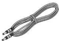
Remote cable

Ferrite clamp cores for a commercially available BNC cable and DVI cable (×2)
(For RGB1 connector and DVI DIGITAL Input connector. See page E-27 for Installation Instructions.)
Getting to Know Your GT2150 Projector

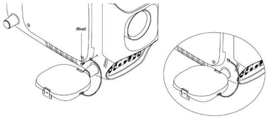
Attaching the lens hood cap to the lens hood with the supplied string and rivet
- Thread the string through the hole on the lens hood cap.

- Use the river to attach the string to the bottom of the projector.
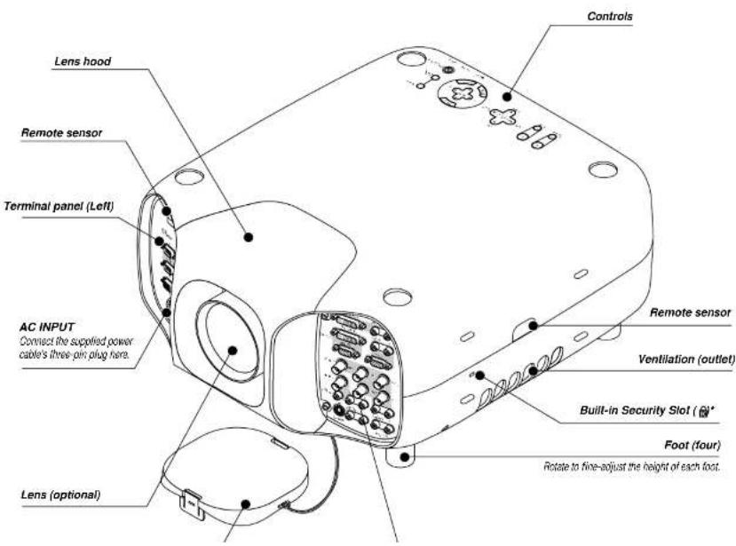
Top Features

1. Power Button (ON / STAND BY) (○)
Use this button to turn the power on and off when the power is supplied and the projector is in standby mode.
NOTE: To turn off the projector, press and hold this button for a minimum of two seconds.
2. Auto Adjust Button (RGB only)
Use this button to adjust Position-H/V and Pixel Clock for an optimal picture. Some signals may not be displayed correctly or take time to switch between sources.
3. Source Button
Use this button to select a video source such as a PC, VCR or DVD player.
Each time this button is pressed, the input source will change as follows:
8 Lens Shift Button
Adjust the lens offset by shifting the projected image position horizontally and / or vertically.
9 Zoom Button
Zoom the lens in and out.
10 Focus Button
Adjust the lens focus.
11. Lamp Remaining Indicator
Indicates the lamp remaining amount. See the Lamp Light Messages on page E-56 for more details.
12. Status Indicator
When this is lit red (orange in Eco mode) continually, it's warning you that the projection lamp has reached the end of its usable life (1500
Front Terminal Panel (Right)

- DVI DIGITAL Input Connector (DVI-D)
This connector can be used to accept digital signal output from a computer with a DVI connector.
- DVI DIGITAL Audio Input Jacks (RCA)
These are the left channel and the right audio inputs for stereo sound coming from the equipment connected to a computer with DVI output
- DVI DIGITAL OUTPUT Connector (DVI-D) This connector is used for double stacking.
Use a DVI-D cable (option) to connect the DIGITAL OUTPUT connector of a projector to the DVI DIGITAL input of the following projector until all the projectors are connected.
ANALOG OUTPUT Connector (Mini D-Sub 15 pin) You can use this connector to loop your computer image an external monitor from either the RGB 1 or RGB 2 input source.
- RGB 1 Input Connectors (BNC)
Connect R,G,B,H (Horizontal sync) and V (Vertical sync) outputs of external equipment such as the NEC ISS-6020Switcher.
If using a component with a combined sync (SYNC) output, connect it to the H/V terminal. When using luminance and color-difference signals of HDTV and DVD, connect Pr/Cr to the R,Y to the G and Pb/Cb to the B input of the projector.
- RGB 1 Audio Input Jacks (RCA) L/MONO
This is your left channel audio input for stereo sound coming from the RGB Input 1 source. This also serves as your monaural audio input.
This is your right channel audio input for stereo sound from the RGB Input 1 source.
- VIDEO 1 Input Connector (BNC)
Connect a VCR. DVD player, laser disc player, or document camera here to project video.
- VIDEO 2 Input Connector (RCA)
Connect a VCR, DVD player, laser disc player, or document camera here to project video.
- VIDEO Audio Input Jacks (RCA)
LIMONO
This is your left channel audio input for stereo sound coming from the
Front Terminal Panel (Left)

- PC CONTROL Connectors (MInl D-Sub 9 pin)
For system expansion such as PC-Control.
IN: connect to the external equipment such as PC.
OUT: for daisy-chaining multiple projectors and operating them with the same external equipment. To do so, connect to a second projector's IN terminal to relay the input at the IN terminal of the first projector until all the projectors are connected.
Inserting or Ejecting a CompactFlash Card
CAUTION: DO NOT EJECT THE CompactFlash CARD, TURN OFF THE POWER, OR UNPLUG THE POWER CABLE of the projector while the PC card access indicator light shows that data is being accessed. Doing so could cause damage to the CompactFlash card.
Inserting
Insert the CompactFlash card into PC Card Slot with its TOP FACING DOWN.

Removing
Press the PC Card Eject button. The CompactFlash card ejects partially, then remove.

When the GT2150 is powered OFF the screen trigger stops sending a low voltage trigger to the screen controller and the screen will go up.
NOTE: Screen Controllers are supplied and supported by screen manufactures. This option is not included with the GT2150 projector.
NOTE: Do not use this jack for anything other than intended use. Connecting the wired remote control to the SC. TRIGGER Mini Jack causes damage to the
Remote Control Features

1. POWER ON
Press this button to turn on the projector when the power is supplied and the projector is in standby mode.
2. POWER OFF
Press and hold this button for a minimum of two seconds to turn off the projector.
3. MENU
Press to display the main menu.
While pressing and holding CTL, press this button to display the Remote Control ID dialog box to specify the remote control ID. See page E-33.
4. ENTER
Executes the menu selection and activates items selected from the menu. When the slider or dialog box is displayed: Pressing this button confirms adjustments/setting and returns to the previous menu display.
5. Select (Up/Down/Left/Right)
▲▼: Use these buttons to select the menu of the item you wish to adjust.
When no menus appear, these buttons work as a volume control.
◀▶: Use these buttons to change the level of a selected menu item. A press of the ▶ button executes the selection.
Pressing and holding CTL, then pressing ◀ button works as a Back Space key in the entry screen. Pressing and holding CTL, then pressing this button moves the menu, slider, toolbar or dialog box.
6. ADJUST WHITE BAL
Press to display the Color adjustment screen. Pressing this button sequentially selects "Color Temperature" → "White Balance - Brightness" → "White Balance - Contrast" → "Signal Level" → "Ref.White Bal" → "Switcher Gain".
7. ADJUST PICTURE
Press to display the Picture adjustment screen. Pressing this button sequentially selects 'Brightness' → "Contrast" → "Saturation" → "Color" → "Hue" → "Sharpness" → "V-Aperture" → "Gamma Correction".
10. UNDO
Press to return the adjustments and settings to the previous condition. While pressing and holding CTL, pressing this button clears the entire menus or adjustment/setting screen. At this time the adjustments/setings are stored in memory except the items on the setting screen with "OK" and "Cancel" buttons such as the Menu and the Setup screen.
11. CANCEL
Press to exit the menu. Press this button with CTL to return to the previous menu without closing adjustment/setting screen while the menus appear. This feature allows you to adjust or set several items concurrently.
12. INFO
Displays the "Source Information" or "Projector Information" window. This button toggles between these two windows.
13. TEST
Press to display the test pattern. Pressing this button sequentially selects six test patterns.
14. HELP
Provides online help.
15. PIXEL
Displays the Position/Clock screen to adjust the clock and phase.
16. AUTO (RGB only)
Press to adjust Position-H/V and Pixel Clock for an optimal picture.
17. POSITION
Press to display the Blanking screen; press again to display the Position screen.
While pressing and holding CTL, pressing this button displays the Lens Shift adjustment screen.
18. MUTE SOUND
Turns off the sound for a short period of time. Press again to restore the sound.
19. MUTE OSD
Press to turn off the on-screen display. Press again to restore the on-screen display.
24. FOCUS (+/-)
While pressing and holding CTL, pressing this button allows you to adjust the lens focus.
25. MAGNIFY/ZOOM (+/-)
Magnify the size of a target portion.
While pressing and holding CTL, pressing this button allows you to zoom the lens in and out.
26. CTL
Used in conjunction with other buttons, similar to a shift key on a computer.
27. Remote Jack
Connect your remote control cable here for wired operation.
28. Infrared Transmitter
Direct the remote control toward the remote sensor on the projector cabinet.

Remote Control Precautions
• The remote control system may not function when direct sunlight or strong illumination strikes the remote control sensor of the main unit, or when there is an obstacle in the path.
- When remote control buttons are pressed and held, projector's function keys may not operate.
- Do not subject to strong shock.
- Do not allow water or other liquid to splash on the remote control. If the remote control gets wet, wipe it dry immediately.
- Avoid exposure to heat and steam.
- Remove the batteries from the remote control when the remote control is not going to be used for a long period.
Remote Control Battery Installation
Installing the Remote Control Batteries When it comes time to replace the batteries, two "AAA" type will be required.
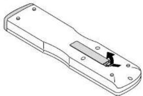
- Press and open the cover.
natural_image
Technical line drawing of a rectangular electronic device with a slot and mounting holes (no text or symbols)- Align and insert the batteries according to the (+) and (-) indications inside the case.

Operating Range for Wireless Remote Control
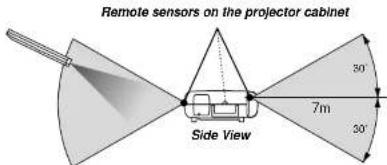
The infrared signal operates by line-of-sight up to a distance of approximately 7m (20 feet) and a 60 degree angle of the remote sensor. The projector will not function if there are objects between the remote sensor and the remote control or if strong light falls on the remote sensor. Weak batteries will also prevent the projector from operating properly.

Using the Remote Control in Wired Operation
Connect one end of the supplied remote cable to the REMOTE 2 IN
mini jack and the other end to the remote jack on the remote control.

Terminal panel (Left)
2. INSTALLATION
This section describes how to set up your GT2150 projector and how to connect video and audio sources.
Setting Up Your GT2150 Projector
Your GT2150 Projector is simple to set up and use. But before you get started, you must first:
- Determine the image size
- Set up a screen or select a non-glossy white wall onto which you
can project your image - Install the optional lens to the projector.
Screen Size and Projection Distance
Applicable lens and throw distance/ List of screen sizes

List of Screen Sizes
| Screen size Width (H) | Height (V) | |||
| m inch | r inch | |||
| 47" 0.8315 | 50.6 | 23.6 | ||
| 57" 1.2472 | 20.9 | 35.4 | ||
| 57" 1.6630 | 1.2 | 47.2 | ||
| 100" 2.0787 | 1.5 | 59.1 | ||
| 120" 2.4945 | 1.8 | 70.9 | ||
| 150" 3.0118 | 1.2 | 90.5 | ||
| 200" 4.1161 | 1.4 | 118.1 | ||
| 250" 5.1200 | 0.8 | 149.5 | ||
| 300" 6.1230 | 2.4 | 181.1 | ||
| 400" 8.1318 | 9.6 | 240.2 | ||
| 500" 10.2401 | 6.7 | 299.2 | ||
Formulas: Screen width H (m) = Screen Diagonal (4:3) × 4/5 × 0.0254
Screen height V (m)= Screen Diagonal (4:3)×3/5×0.0254
Screen width H (inch)= Screen size × 4/5
Screen height V (inch)= Screen size × 3/5
Table of Throw Distances and Screen Sizes for Optional Lenses
| LENS | Model | GT10RL | GT13ZL | GT19ZL | GT34ZL | ||||||||||
| Magnifastion | 1.0 | 1.3 - 1.6 | 1.8 - 2.4 | 3.4 - 5.2 | |||||||||||
| Green Size (Diagonal) | 40" | m | Inch | m | Inch | - | m | Inch | m | Inch | - | m | Inch | - | m |
| 0.8 | 31.5 | 1.1 | 43.3 | - | 1.3 | 51.2 | 1.5 | 59.1 | - | 2.0 | 78.7 | - | - | ||
| 60" | 1.2 | 47.2 | 1.6 | 63.0 | - | 2.0 | 78.7 | 2.2 | 86.6 | - | 2.9 | 114.2 | - | - | |
| 67" | 1.3 | 51.2 | 1.7 | 66.9 | - | 2.1 | 82.7 | 2.5 | 98.4 | - | 3.2 | 126.0 | - | - | |
| 72" | 1.4 | 55.1 | 1.9 | 74.8 | - | 2.3 | 90.6 | 2.6 | 102.4 | - | 3.5 | 137.8 | - | - | |
| 80" | 1.6 | 63.0 | 2.1 | 82.7 | - | 2.6 | 102.4 | 2.9 | 114.2 | - | 3.9 | 153.5 | 5.5 | 216.5 | |
| 84" | 1.7 | 66.9 | 2.2 | 86.6 | - | 2.7 | 106.3 | 3.1 | 122.0 | - | 4.1 | 161.4 | 5.9 | 232.3 | |
| 90" | 1.8 | 70.9 | 2.3 | 90.6 | - | 2.9 | 114.2 | 3.3 | 129.9 | - | 4.3 | 169.3 | 6.3 | 248.0 | |
| 100" | 2.0 | 78.7 | 2.6 | 102.4 | - | 3.3 | 129.9 | 3.7 | 145.7 | - | 4.9 | 192.9 | 6.9 | 271.7 | |
| 120" | 2.4 | 94.5 | 3.2 | 126.0 | - | 3.9 | 153.5 | 4.4 | 173.2 | - | 5.9 | 232.3 | 8.3 | 326.8 | |
| 150" | 3.0 | 116.1 | 4.0 | 157.5 | - | 4.9 | 192.9 | 5.5 | 216.5 | - | 7.3 | 287.4 | 10.4 | 429.4 | |
| 180" | 3.7 | 145.7 | 4.7 | 185.0 | - | 5.8 | 228.3 | 6.7 | 263.8 | - | 8.8 | 340.5 | 12.6 | 503.9 | |
| 200" | 4.1 | 161.4 | 5.3 | 208.7 | - | 6.5 | 255.9 | 7.3 | 287.4 | - | 9.8 | 385.8 | 13.6 | 543.3 | |
| 240" | 4.2 | 180.2 | 5.5 | 216.5 | - | 8.0 | 287.7 | 7.0 | 314.0 | - | 10.2 | 405.5 | 15.0 | 600.8 | |
Lens Shift Adjustable Range
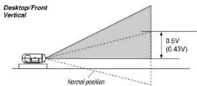
Lens Shift Range for Desktop and Ceiling Mount Application The diagram below shows the location of the image position in the lens. The lens can be shifted within the shaded area as shown using the normal projection position as a starting point.
NOTE: Lens shift feature is not available on GT10RL(fixed lens).
Maximum Possible Range for GT19ZL/GT34ZL (GT13ZL):
Up: 0.5 V (0.43V)
Down: 0.5 V (0.43V)
Right: 0.25 H
Left: 0.25 H (H: width of projected image, V: height of projected image)
NOTE: If lens is shifted in two directions combined, maximum range in either direction cannot be obtained due to rounded off area near edge of lens. (example: shift up and right) See diagram below.


Horizontal
Normal position

Optional Lens Installation
This section describes how to install the lens.
Before installation
* Determine the optional lens to be used to obtain a desired projection distance. There are four optional lenses available:
GT10RL (Fixed short throw lens)
GT19ZL, GT13ZL and GT34ZL (Zoom lens)
* Press the power button (ON/STAND BY) on the projector or POWER OFF button on the remote control, wait three minutes for the cooling fan to stop, then
disconnect the power cable
Check that the projector has cooled off sufficiently before proceeding.
CAUTION
* The projector and lens contain high-precision parts. Do not induce shock to the projector or the lens.
* Do not touch the lens surface. Doing so can degrade the optical performance.
Preparation: Tools needed for installation:
A hexagonal driver and dust-protective sheets are supplied with the optional lens.
- Remove the lens hood cap and lens hood.
① Press and hold the catches on both ends of the lens hood cap, and 2 then remove it.
③ Loosen the 4 screws on the lens hood using the hexagonal driver until the hexagonal driver goes into a freewheeling condition and remove the lens hood. The 4 screws are not removable.

- Mount the lens unit on the projector and connect the extension cable attached to the projector.
1 Remove the lens cap from the rear end of the lens unit.
2 Insert the lens unit so that the 4 screws on the lens unit are properly lined up with the 4 holes on the lens mount.
2. Secure the 4 screws using the hexagonal driver.
4 Insert the connector of the lens unit fully into the socket of the extension cable attached to the projector.
NOTE: Leave the front lens cap for protection while mounting the lens unit.

- Reinstall the lens hood.
1 Remove the front lens cap from the lens unit.
2 Insert the lens hood so that the grooves on the 4 corners of the lens hood are properly lined up with the 4 catches on the projector.
② Secure the 4 screws using the hexagonal driver.
This completes installation. 4 If necessary, put the lens hood cap on the lens hood.

Setting up for Double Stacking in Link Mode

NOTE: Up to two units can be gravity stacked without external support. In some cases, however, two images will not align on the screen correctly. This will become more apparent when displaying small text and detailed graphics.
CAUTION: To prevent the projectors from falling, install them in a place and fasten them in a way with sufficient strength to support the two projectors.
NOTE: SW 1 Level and SW 2 Level of Switcher Control are not available on Link Mode.
For double stacking, follow the instructions described below.
1) Stacking the Projectors
1-1. Place the projectors at the proper height for best screen to projec-
3-1-3. Display all desired input signals, make adjustment to each signal, then save all adjustments on the master projector. (Adjustments will be saved automatically.)
3-1-4. Turn the master projector off (standby mode).
3-1-5. Store all the adjustments on a CompactFlash card from the master projector.
3-1-5-1. Insert a CompactFlash card into the PC Card slot.
NOTE: Be sure to insert a CompactFlash card into the PC Card slot with its front side facing downward.
3-1-5-2. Press and hold CANCEJ, then press POWER on the top panel of the master projector. The POWER indicator will change to steady green and the PC Card Access indicator will start flashing. After storing data on the CompactFlash card, the POWER indicator will change to orange.
5-1-5-3. Remove the CompactFlash card from the slot of the master projector.
3-1-6. Transfer the data to the other slave projector using the CompactFlash card so that all the projectors have the same data in memory.
3-1-6-1. Insert the CompactFlash card into the slot of the slave projector.
NOTE: Since data in the slave projector will be lost at this time, make backup copies of them before proceeding.
3-1-6-2. Press and hold ENTER, then press MENU on the top panel of the slave projector. The POWER indicator will change to steady green and the PC Card Access indicator will start flashing to indicate that the data is being copied from the CompactFlash card to the slave projector. After copying data to the slave projector, the POWER indicator will change to orange.
3-1-6-3. Remove the CompactFlash card from the slave projector.
NOTE: If you select the RGB1 input on the master projector, you must select the same input on the slave projector and the RGB2 on the master projector and the slave projector.
NOTE: After adjusting and registering signals as mentioned above, you must change the input to RGB on the Entry Edit Command window for Link Mode. See "Entry List Edit" on page E-41 for changing to RGB source.
6) Link Mode Setting
6-1 Assign a unique Projector ID for each projector.
6-1-1. Select [Projector Options] → [Setup] → [Page 5] → [Projector ID]. See page E: 50 for specifying ID.
6-1-2. Specify a unique projector ID for each projector.
6-2 Select the same communication speed for all the projectors.
6-2-1. Select |Projector Options| → |Setup| → |Page 5| → |Communication Speed|. See page E-50 for setting the communication speed.
6-2-2. Select the appropriate speed between 4800 and 38400.
6-3 Set the Link Mode on each projector.
6-3-1. Select [Projector Options] → [Link Mode].
6-3-2. First select [Slave] on the slave projector.
6-3-3. Select [Master] on the master projector. See page 1-50 for setting Link Mode.
6-4 Project a source image from all projectors
6-4-1. Display any signal unto the screen.
6-4-2. Check to see if the images on the master projector are displayed in synchronization with the ones on the other slave projector while the projectors are in link mode.
NOTE: Registering signals is not possible in the Link mode. To register a signal, first set "Link Mode" to "Standalone" on the menu and then repeat the above steps from 3. If you select an unregistered signal, the master projector displays the image, but the slave projector doesn't. To view the information on the currently displayed signal, select [Help] - [Source Information] - [Page1].
6-5 Make adjustments to the slave projector.
NOTE: See "List of Menu Items Available on Link Mode" on page E-62 for more information.
Projector Orientation
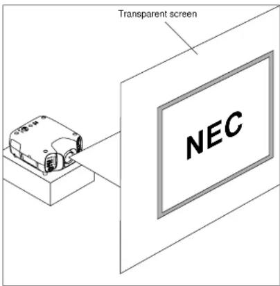
An image can be projected from in front or behind a screen, and the projector can be installed on the ceiling*.
Ceiling Front Projection
Use [Projector Options] · [Setup] · [Page 1] · [Orientation] to select "Ceiling Front". (See page E-49.)

Ceiling Rear Projection
Use [Projector Options] - [Setup] - [Page 1] - [Orientation] to select "Ceiling Rear". (See page E-49.)
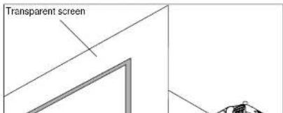
Desktop Rear Projection
Use [Projector Options] → [Setup] → [Page 1] → [Orientation] to select "Desktop Rear". (See page E-49.)
WARNING
• Installing your projector on the ceiling must be done by a qualified technician. Contact your NEC dealer for more information.
* Do not attempt to install the projector yourself.
- Only use your projector on a solid, level surface. If the projector falls to the ground, you can be injured and the projector severely damaged.
- Do not use the projector where temperatures vary greatly. The projector must be used at temperatures between 32^ (0°C) and 95°F (35°C).
- Do not expose the projector to moisture, dust, or smoke. This will harm the screen image.
- Ensure that you have adequate ventilation around your projector so
3. BASIC OPERATION
Connecting the Power Cable and Turn on the Projector
Before you turn on your projector, ensure that the computer or video source is turned on and that your lens hood cap is removed.
- Connect the supplied power cable to the projector.
Plug the supplied power cable in the wall outlet. The projector will go into its standby mode and the power indicator will glow orange.

natural_image
Technical line drawing of a vehicle front panel with internal components and connectors (no text or symbols)- Turn on and off the Projector.
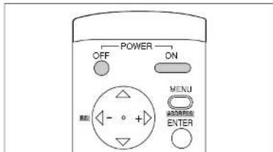

To turn off the projector:
First press the Power (ON/STANDBY) button on the projector cabinet or the POWER OFF button on the remote control for a minimum of two seconds. The power indicator will glow orange. After the projector turns off, the cooling fans keep operating for three minutes.
NOTE: Do not disconnect the power cable during this time. Then, unplug the power cable. The power indicator will go out.
Status of indicators: Off
POWER

Fan running Stand by

About Startup Screen
(Menu Language Select screen)
When you first turn on the projector, you will get the Startup screen.
This screen gives you the opportunity to select one of the seven menu languages: English, German.
French, Italian, Spanish, Swedish and Japanese.
To select a menu language, follow these steps:
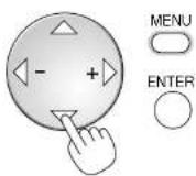
- Use the Select ▲ or ▼ button to select one of the seven languages for the menu.

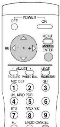
- Press the Enter button to execute the selection
Set up the projector
-
Turn on the projector
-
Select your type of projection:
Desktop front, ceiling rear, desktop rear, and ceiling front.

- Display the test pattern by pressing the TEST button on the remote control or using the menu.

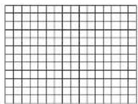
- Adjust the image position and the image size.
(1) Press and hold the CTL button and press the POSITION button to display the Lens Shift adjustment screen. Use the Select button on the remote control or the LENS SHIFT button on the projector cabinet to move the image horizontally and vertically. To close the Lens Shift adjustment screen, press the CANCEL button. See page E-13 for "Lens Shift Adjustable Range".


(2) Press and hold the CTL and press the ZOOM + or - button to adjust the image size. You can also adjust the image size by using the ZOOM + or - button on the projector cabinet.

(3) Press and hold the CTL button and press the FOCUS + or - button to obtain the best focus. You can also adjust the focus by using the FOCUS + or - button on the projector cabinet.
Other adjustments
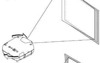
Rotate the projector to make the image square.
natural_image
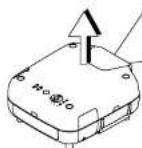
Diagram of a device with light rays projecting onto a screen (no text or symbols)Rotate the four feet to make the image square to the screen.
natural_image
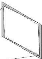
Simple line drawing of a tilted rectangular frame with no text or symbolsEach of the feet height can be changed up to 20 mm (0.78") or at angles up to 3.5 degrees.
Use keystone correction for proper adjustment.

natural_image
Line drawing of a device with a triangular pointer and a label 'H-4010' (no other text or symbols)
natural_image
Technical line drawing of a mechanical component with no visible text or symbols4. CONNECTIONS
When used in standalone operation
Connecting Your VCR Or Laser Disc Player
Use common RCA cables (not provided) to connect your VCR or laser disc player to your GT2150 Projector. To make these connections, simply:
-
Turn off the power to your projector and VCR or laser disc player.
-
Connect one end of your RCA cable to the video output connector on the back of your VCR or laser disc player, connect the other end to the Video input on your projector. Use standard RCA audio patch cords to connect the audio from your VCR or laser disc player to your projector (if your VCR or laser disc player has this capability). Be careful to keep your right and left channel connections correct for stereo sound.
-
Turn on the projector and the VCR or laser disc player.
NOTE: Refer to your VCR or laser disc player owner's manual for more information about your equipment's video output requirements.
VCR or other video equipment


Connecting Your DVD Player with Component Output
Use the optional Component V cable to connect your DVD player with the component output to your GT2150 Projector. To make these connections, simply:
- Turn off the power to your projector and DVD player.
- Use the optional Component V cable to connect your DVD player to the RGB / input or use a D-Sub 15 pin cable to the RGB 2 input of your GT2150 projector.
- Turn on the projector and the DVD player.

Connecting Your PC Or Macintosh Computer
Connecting your PC or Macintosh computer to GT2150 Projector will enable you to project your computer's screen image for an impressive presentation.
To connect to a PC or Macintosh :
- Turn off the power to your projector and computer.
- Use an RGB signal cable (not supplied) to connect your PC or Macintosh computer to the projector.
- Turn on the projector and the computer.
- If the projector goes blank after a period of inactivity, it may be caused by a screen saver installed on the computer.

Connecting a PC with DVI output
The DVI (digital) input accepts up to the SXGA@60Hz signal.
SXGA signals with 110 MHz or over of pixel clock cannot be supported.
NOTE: The Auto Adjust feature does not work for DVI digital signal. When DVI signal is selected and the image position is not corrected, adjust the horizontal and vertical position using the Position/Clock screen. See page E-43 for more details.

Using OUTPUT Connectors
You can connect a separate, external monitor to your GT2150 projector to simultaneously view on a monitor the RGB analog, or component image you're projecting. To do so:
-
Turn off the power to your projector, monitor and computer.
-
Use a 15-pin cable to connect your monitor to the ANALOG OUT-
PUT (Mini D-Sub 15 pin) connector on your projector
- Turn on the projector, monitor and the computer.
NOTE: The ANALOG OUTPUT connector outputs RGB signal during standby. When the projector goes into standby, the image on an external monitor disappears for a moment.
The DVI DIGITAL OUTPUT connector outputs all input signals.
The DVI DIGITAL OUTPUT connector is designed for Link mode only. Do not connect the other equipment than another projector to this connector.

Connecting to a Single Workstation
You can connect a workstation to your GT2150 projector. To do so:
- Turn off the power to your projector and workstation.
- Use a BNC x 5 cable to connect your workstation and the RGB 1 connectors on your projector.
- Turn on the projector and a workstation.

When Used with One Switcher (ISS-6020/ISS-6020G)
Up to 10 input signals can be accepted when the projector is connected to one Switcher. Using the projector with the Switcher allows easy adjustment and signal selection.

When Used with Two or More Switchers (100 Inputs)
Up to 100 inputs can be accepted using the NEC ISS-6020 Switcher.
How to make connections:
1 Connect the REMOTE 1 terminal of the master Switcher to the REMOTE 1 of the projector using the optional control cable (15p-15p/CTL-6010).
2 Next connect the REMOTE 2 terminal of the master Switcher to the REMOTE 1 terminal of the first slave. Switcher using the same optional control cable as mentioned above. Third, connect the REMOTE 2 terminal of the first slave to the REMOTE 1 of the second slave, and the REMOTE 2 terminal of the second slave to the REMOTE 1 terminal of the third slave (and the REMOTE 2 of the ninth slave to the REMOTE 1 of the tenth slave). Connect all the Switchers with optional control cables.
- Select [Projector Options] -> [Switcher Control] -> [SW2 Level]. See page E-51 for the information in detail.
• Refer to the user's manual accompanying the Switcher
• Cables mentioned are not included with the projector.
NOTE:
- Be sure to set all the slide switches (S8603) of the Switcher to RS-422 positions. Set the one on the last slave Switcher to the appropriate position to match the connected equipment such as a personal computer. (RS-422/RS-232C for PC control of projector)
- Set the DIP switch S8601 of the Switcher.

flowchart
graph TD
    A["To RS232C"] --> B["Personal Computer"]
    C["To REMOTE 1"] --> D["Slave 1"]
    E["To REMOTE 1"] --> F["Slave 2"]
    G["To REMOTE 2"] --> D
    H["To REMOTE 1"] --> I["Slave 2"]
    J["To Slot 1-10"] --> D
Set the DIP switch (S8601) of the Switcher as follows:
NOTE: Slave numbers 1 to 10 must correspond to the master's slot numbers 1 to 10.
| ISS-6020 ISS-6020G | Output to | Setting of S8601 |
| Master | The Projector |  |
| Slave 1 | Slot 1 of the Master |  |
| Slave 2 | Slot 2 of the Master |  |
| Slave 3 | Slot 3 of the Master |  |
| Slave 4 | Slot 4 of the Master | 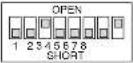 |
| Slave 5 | Slot 5 of the Master |  |
| Slave 6 | Slot 6 of the Master |  |
REMOTE 1 Connector

2 3
This connector is used for either connecting the ISS-6020/ISS-6020G Switcher or a third party external control device. When the Switcher is used, connect it with the optional control cable (15-15 pin; 50 ft./16m; CTL-6010) to this connector.
When used with the Switcher.
| Pln No. FUNCTION | |
| 1, 2, 6 and 7 Sending and receiving data when the Switchor is used. | |
| 9 Identifying the Projector | |
| 15 Ground | |
| 8,11 and 12 Used inside the Projector. Normally set to OPEN. | |
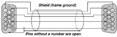
When using with the Switcher ISS-6020/ISS-6020G, connect No. 1,2,6,7,9 and 15 pins of the projector to the same No. pins of the switcher as shown below.
Pin Configuration of Optional CTL-6010 Cable
REMOTE 1 connector of the Projector mini D-sub 15 pin (female)
REMOTE 1 connector of the Switcher mini D-sub 15 pin (female)
When used in stand alone operation.
| Pin No. | SHORT/OPEN | FUNCTION | |||
| 14 | SHORTOPEN | External control mode ONExternal control mode OFF | |||
| 5 | SHORTOPEN | POWER ONPOWER OFF | |||
| 10 | SHORTOPEN | PICTURE MUTE ONPICTURE MUTE OFF | |||
| 3 | SHORTOPEN | MUTE SOUND ONMUTE SOUND OFF | |||
| 4,8,12,11 | 11pin | 12pin | 8pin | 4pin | |
| OPEN | OPEN | OPEN | OPEN | RGB 1 | |
| OPEN | OPEN | OPEN | SHORT | VIDEO 1 | |
| OPEN | OPEN | SHORT | OPEN | S-VIDEO | |
| OPEN | SHORT | OPEN | SHORT | RGB 2 | |
| OPEN | SHORT | SHORT | OPEN | VIDEO 2 | |
| OPEN | SHORT | SHORT | SHORT | RGB1 (S-VIDEO) | |
| SHORT | OPEN | OPEN | OPEN | DVI (DIGITAL) | |
| SHORT | OPEN | SHORT | SHORT | RGB1 (VIDEO) | |
* When the combinations other than specified in the above table are selected, the input will be forcefully switched to RGB 1.
* The term "SHORT" means to connect with pin 15
* When in the external control mode, the POWER. Source/Alphanumeric. PICTURE MUTE and SOUND MUTE
buttons on the remote control will not function.
* When the External control mode is set to ON, the following settings are not effective: Timer, Power Manage-
ment. Power Confirmation. Default Source Select
NOTE: Pin 13 is the external remote signal terminal. The projector can be controlled by the same format signal as the supplied remote control from the external controller regardless of setting on Pin 14.
Operating Multiple Projector with Remote Control
You can operate multiple projectors with the same remote control in wireless operation.
To do so:
- Select [Projector Options] → [Setup] → [Page 5] → [Projector ID] and assign an ID number to each projector. See also page E-50.
- On the remote control specify the ID number of the projector to be adjusted. Press and hold the CTL and press MENU (ADDRESS) button to enter the ID number.
You can operate the projector assigned the same ID number as the remote control.
Projector ID=01

Projector ID=02 Projector ID=03


Remote Address = 03
You can daisy-chain multiple projectors and operate them separately with the same remote control in wired operation. To do so:
1) Use the remote control cable to connect the REMOTE 2 Output of one projector to the REMOTE 2 Input of the next projector until all the projectors are connected. Only one remote control cable is supplied with each projector.
2) Specify a unique projector ID for each projector.
3) Specify the same remote address as the projector ID to be adjusted.
NOTE: Specifying "None" for projector ID allows you to operate multiple projectors concurrently. However, some projectors may not synchronize to the other projectors.
Using the PC CONTROL connectors
The Link mode function allows you to adjust or set multiple projectors using the DVI DIGITAL OUTPUT and the PC CONTROL connectors.
Connection for Double Stacking in Link Mode

5. OPERATION
This section describes how to select a computer or video source, adjust the picture and sound, edit a signal and adjust all other settings and adjustments for proper projector set-up.
General Controls
Before you turn on the projector ensure that the computer or video source is turned on and that the lens hood cap is removed.
1. Turn on the Projector
Plug the supplied power cable in the wall outlet. The projector will go into its standby mode and the power indicator will glow orange.
Only after you press the "POWER ON" button on the remote control ("ON/STAND BY" button on the projector cabinet) will the power indicator turn to green and the projector become ready to use.
2. Select The Computer Or Video Source
Press one of the Source buttons on the remote control to select the desired source. Or press the MENU button on the remote control and use the Source Select to select your video source: Video, S-Video, RGB or DVI digital.
3. Adjust The Image
Press the ADJUST PICTURE button on the remote control or use the menu to adjust the picture.
4. Turn Off The Projector
First press the "POWER OFF" button on the remote control ("ON/STAND BY" button on the projector cabinet) for a minimum of two seconds. The power indicator will glow orange. Then, unplug the power cable. The power indicator will go out.
IMPORTANT:
• The projector should be unplugged if it will not be used for an extended period.
- If you want to turn off the image briefly (five minutes or less), press the MUTE PICTURE button instead of turning the projector off and on.
- The projector will display a black, blue image or logo if no input signal is present.
- Do not turn the projector off and then immediately back on. The Projector needs to cool down for ONE minutes before it is powered on again
Using the Menus
-
Press the "Menu" button on the remote control or projector cabinet to display the menu.
-
Press the ▲▼ buttons on the remote control or the projector cabinet to highlight the menu for the item you want to adjust or set.
-
Press the ▶ button or the "Enter" button on the projector cabinet or the remote control to select a submenu or item. NOTE: The right-oriented delta symbol indicates further choices are available.
-
Adjust the level or turn the selected item on or off by using "Select"◀ or ▶ buttons on the remote control or the cabinet. The on-screen slide bar will show you the amount of increase or decrease.
-
Changes are stored until you adjust it again.
ENTER ...... Stores the setting or adjustments.
CANCEL ..... Return to the previous screen without storing settings or adjustments.
NOTE: The change is stored automatically when any one of the following procedures is performed:
* The on-screen disappears.
* The projector goes into standby.
* One input is switched to another.
- Repeat steps 2-5 to adjust an additional item, or press "Cancel" on the projector cabinet or the remote control to quit the menu display.
Customizing Basic/Custom Menu
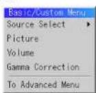
The Basic/Custom menu can be customized to meet your requirements. Selecting a menu item from the "Basic/Custom Menu Edit" list, allows you to custom tailor the menu items to your needs.
- Select "Basic/Custom Menu Edit" to display the "Basic/Custom Menu Edit" screen.
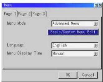
- Use the ▲ or ▼ button to highlight your selection and press the Enter button to place a check mark next to an option. This action enables that feature. Press the Enter button again to clear the check box.

- In order for the changes to take effect, use the ▶ or ▶ button on the remote control or the projector cabinet to highlight "OK", then press the Enter button. To cancel the changes, use the ▲ or ▼ buttons to highlight "Cancel" and press the "Enter" button. To return to the factory default, select "Reset" then press the "Enter" button.
The default Basic/Custom Menu Items are:
Source Select (RGB1/2, DVI DIGITAL, Video1/2, S-Video and Entry List), Brightness, Contrast, Pixel Adjust and Position.
NOTE: Once you have selected OK on the Basic/Custom Menu Edit screen, you cannot cancel the changes on the Menu screen. However, you can re-edit the menu items over again as described in the steps above.
NOTE: If the "Advanced Menu" item has been selected on the Menu mode, you get the "Confirmation Change Menu" upon completion of "Basic/Custom Menu" editing. In this case, selecting "Yes" then "Enter" will close all the menus and apply the changes from the Advanced menu to the Basic/Custom Menu. If you select "No" then "Enter" functions, then all menu items will return to the Advanced menu, but your changes will still be available within the "Basic/Custom Menu" selection. To display the previously tailored Basic/Custom Menu, select "Basic/Custom Menu" from the "Menu Mode".

An Item "To Advanced Menu" will be added to the bottom of the Basic Custom Menu. Selecting this item and pressing the "Enter" button will display the "Advanced Menu" features.
List of Direct Button Combinations
| CTL+ SOURCE (1-10) Switches to any selected signal found in the Entry List.To enable this combination, you must first assign specific remote buttons for direct input selection in the Entry Edit window. | |
| CTL+ ENTER (While displaying Entry list) Displays the Entry Edit Command window. | |
| CTL+CANCEL Returns to the previous menu without closing the slidebar or dialog. | |
| CTL+ UNDO Clears all menus or adjustment/setting screens. All adjustments are saved automatically. | |
| CTL+ ◀/▶/ ▲/ ▼ | Moves the slidebar or dialog box horizontally or vertically. |
| While using zoom on remote control: Displays the magnifying glass icon. | |
| CTL+ ◀(BS) Deletes one letter or numeral in the entry screen. | |
| CTL+MUTE OSD Turns off the on-screen display forcefully. | |
| SOURCE (1-10) in SW Level mode Displays the Select switcher Input Slot window.NOTE: This feature is available for SW 2 Level mode only.When the SW 1 Level mode is selected, pressing Source button switches to the corresponding slot without displaying the Select Slot window. | |
| CTL+ MENU (ADDRESS) Displays the remote ID entry window. | |
| CTL+ IMAGE (PROJECTOR) Sequentially selects the Projector Options sub menu. | |
| CTL+ POSITION (LENS) Displays the Lens Shift adjustment window. | |
| CTL+ KEYSTONE (R) | Tums on red. Available only when the projector is in the test pattern mode. |
| CTL+ AMPLITUDE (G) | Tums on green. Available only when the projector is in the test pattern mode. |
| CTL+ ENTRY LIST (B) | Turns on blue. Available only when the projector is in the test pattern mode.Pressing and holding down CTL and then ENTRY LIST buttons simultaneously, enters a signal in the Entry List when you are not displaying a test pattern. |
Menu tree

flowchart
graph TD
    A["Advanced Monu"] --> B["Source Select"]
    B --> C["Adjust (Source)"]
    C --> D["Volume"]
    D --> E["Ref Adj"]
    E --> F["Factory Default"]
    F --> G["Projector Options"]
    G --> H["Help"]
    H --> I["Test Pattern"]

    J["Switcher"] --> K["Entry List"]

    L["Standalone"] --> M["RGB1"]
    L --> N["RGB2"]
    L --> O["DVI (DIGITAL)"]
    L --> P["Video1"]
    L --> Q["Video2"]
    L --> R["S-Video"]
    L --> S["RGB1 (VIDEO)"]
    L --> T["RGB1 (S-VIDEO)"]
    L --> U["Entry List"]

    V["Brightness"] --> W["Contrast"]
    W --> X["Saturation 0-100"]
    X --> Y["Color"]
    Y --> Z["Hue"]
    Z --> AA["Sharpness"]
    AA --> AB["V-Aperture"]
    AB --> AC["Gamma Correction Normal/Natural 1/Natural 2"]

    AD["Color Temperature"] --> AE["Brightness Brightness R/G/B"]
    AD --> AF["Contrast Contrast R/G/B"]
    AD --> AG["Signal Level R/G/B, Y/Cb/Cr, Y/Ph/Pr"]

    AH["Picture"] --> AI["White Bayesian Image Video Adj Option Adj Signal Type Switcher"]

    AJ["Pixel Adjust"] --> AK["Clock/Phase Position Horizontal/Vertical"]
    AJ --> AL["Aspect Ratio Input Signal 1.25:1/1.33:1/1.78:1/1.85:1/2.35:1 Display Area 1.25:1/1.33:1/1.78:1/1.85:1/2.35:1"]
    AJ --> AM["Resolution Auto/Native"]
    AJ --> AN["Overscan 0%/5%/10%/25%"]
    AJ --> AO["Video Filter"]
    AJ --> AP["Blanking On/Off Top/Bottom/Left/Right"]

    AQ["Noise Reduction"] --> AR["Luminance Off/Low/Medium/High Chrominance Off/Low/Modium/High"]
    AQ --> AS["Color Matrix Select Color Matrix HDTV/SDTV Select Color Matrix Type B-Y/R-Y, U/V, Cb/Cr Pb/Pr IVX"]
    AQ --> AT["Y/C Delay"]
    AQ --> AU["Tolocine Auto/Off"]
    AQ --> AV["Motion Select Still/Adaptive"]
    AQ --> AW["Motion Level"]
    AQ --> AX["Y/H Adjustment"]

flowchart
graph TD
    A["Advanced Menu\nSource Select\nAdjust (Source)\nVolume\nRef Adj\nFactory Default\nProjector Options\nHelp\nTest Pattern"] --> B["Keystone\nLamp Mode\nRet. White Bal."]
    B --> C["Timer\nMenu\nSetup\nLink Mode\nSwitcher Control\nLAN Mode"]
    C --> D["Normal / Eco"]
    C --> E["Brightness R/G/B, Contrast R/G/B"]
    C --> F["On / Off Timor\nExecute Switch (Active / Inactive)\nEdit\nSloop Timor\nProset Time (Off / 0:30 / 1:00 / 1:30 / 2:00)"]
    F --> G["Page 1\nMenu Mode (Basic/Custom Menu, Advanced Menu, Service Menu)\nBasic/Custom Menu Edit\nLanguage (English / German / French / Italian / Spanish / Swedish / Japanese)\nMenu Display Time (Manual / Auto 5 sec / Auto 10 sec / Auto 30 sec)"]
    F --> H["Page 2\nDisplay Select (Date, Time, Input Terminal, Source Name, Projector ID On/Off)\nDate Format (MM/DD/YYYY, MM/DD/YYYY ddd, DD/MM/YYYY, DD/MM/YYYY ddd, YYYY/MM/DD, YYYY/MM/DD ddd, Month DD, YYYY, Month DD, YYYY ddd)\nData, Time Preset"]
    F --> I["Page 3\nMessage (No Input, Clean Filter On/Off)\nDirect Button (Volume Bar, Keystone Bar On/Off)"]
    F --> J["Page 1\nOrientation (Desktop Front / Ceiling Rear / Desktop Rear / Ceiling Front)\nBackground (Blue / Black / Logo)\nS-Video Mode Select (Off / S2)\nRemote Sensor (Front, Back, Left, Right On/Off)"]
    F --> K["Page 2\nSignal Select RGB1 [Auto / RGB / Component"]\nRGB2["Auto / RGB / Component"]\nSync Termination RGB1 (H-Z / 76Q)]
    F --> L["Page 3\nSignal Select Video1 [Auto / NTSC3.58 / NTSC4.43 / PAL / PAL60 / SECAM"]\nVideo2["Auto / NTSC3.58 / NTSC4.43 / PAL / PAL60 / SECAM"]\nS-Video["Auto / NTSC3.58 / NTSC4.43 / PAL / PAL60 / SECAM"]\nRGB1(Video) [Auto / NTSC3.58 / NTSC4.43 / PAL / PAL60 / SECAM]\nRGB1(S-Video) [Auto / NTSC3.58 / NTSC4.43 / PAL / PAL60 / SECAM)]
    F --> M["Page 4\nAuto Adjust (RGB Only) Power Management Power Off Confirmation\nKeystone Save Built-in Speaker Lamp Off Mode\nLast Memory User Name"]
    F --> N["Page 5\nCommunication Speed (4800 / 9600 / 19200 / 36400)\nProjector ID (Enable / Disable) 1-64\ndefault Source Select (Last / Auto / Select)\nStandalone:\n[RGB1/RGB2/DVI (DIGITAL)/Video1/Video2/S-Video"]
Menu Elements


Menu Descriptions & Functions Source Select

Enables you to select a video source such as a VCR, DVD player, laser disc player, computer or document camera depending on what is connected to your inputs.
Press the up/down buttons on your remote control or the projector cabinet to highlight the menu for the item you want to project. * RGB1.2
* DVI DIGITAL
* Video 1,2
* S-Video
* RGB 1 (VIDEO)
* RGB 1 (S-VIDEO)
Swicher

You can select the slot number from 1 to 10 of the Switcher(s) ISS 6020.
When using with a single Switcher ISS-6020:

Entry List
Displays the list of the entry signals. Use the ▲▼ buttons on your remote control or the projector cabinet to select the signal and press the ENTER button on the remote control or the projector cabinet to project the image of the selected source.

Entry Edil Command
You can edit the signal on the entry list.
To do so:
- While pressing and holding CTL, press ENTER on the remote control to display the Entry Edit Command window.

* Cut Enables you to remove a selected signal from the list and place it on the "clipboard" in the projector.
* Copy Enables you to copy a selected signal from the list and place it on the "clipboard" in the projector.
- Paste Enables you to paste the signal placed on the "clipboard" to any other line of the list. To do this, select "Paste" and then select the line number you want to paste to. Last press ENTER.
* Edit Enables you to change source name or assign the direct key.
* All Delete This feature enables you to delete all the registered signals in the Entry List.
* The following buttons are not available for the currently projecting signals:
1) The Cut and Paste buttons on the Entry Edit Command screen
2) The Input Terminal button on the Entry Edit screen
When complete, select OK and press ENTER. To exit without storing setting, select Cancel.

Select "List" and press ENTER to display the direct Key assignment list.
Select "OK" and press ENTER to close the window.
To close the List window, press CANCEL on the remote.

Selecting a new signal that is close to one of the listed signals in horizontal and vertical frequency
Selecting a new signal that is close to one of the listed signals in horizontal and vertical frequency may not display the image correctly because the new signal is considered as one of the registered signals listed in the Entry List. (In this case the Auto Adjust feature may not work correctly.)
To use both signals, use different input terminal (RGB 1 or RGB 2) respectively, or assign specific remote keys for signals.
-
Cut an existing signal from the Entry List.
1) Select another signal other than the one currently projected because the currently projected signal cannot be cut.
2) Press the ENTRY LIST button on the supplied remote control.
3) After selecting the existing signal, press and hold down the CTL button and then the ENTER button simultaneously on the remote control. The Entry Edit Command window will appear. Select "Cut" and press the ENTER button. The selected signal will be deleted from the Entry List. (The signal data is stored in the clipboard.) -
Select the new signal and enter it in the Entry List.
Press and hold down the CTL button and then press the ENTRY LIST button simultaneously on the supplied remote control to enter the signal in the Entry List.
- Paste the signal data that was cut and placed in the clipboard in Step 1
Adjust (Source)
| Picture | |
| White Balance | |
| Image | |
| Video Adj | |
| Option Adj | |
| Signal Type | |
| Switcher |
Picture
| Brightness |
| Contrast |
| Saturation |
| Color |
| Hue |
| Sharpness |
| V-Aperture |
| Gamma Correction |
Brightness
| Adjusts the brightness level or the back raster intensity. |
Contrast
| Adjusts the intensity of the image according to the incoming signal. |
Saturation
| Adjust saturation at the white peak. |
Color
Increases or decreases the color saturation level (not available for RGB).
Hue
Varies the color level from +/- green to +/- blue. The red level is used as reference. This adjustment is only valid for Video and Component inputs (not available for RGB).
Sharpness
Controls the detail of the image for Video (not available for RGB and Component).
V-Aperture
Adjusts edge enhancement in the vertical direction. (not available for RGB)
Gamma Correction
White Balance

Color Temperature
This feature adjusts the color temperature using the slide bar. Move the slide bar to the right to increase the color temperature for a bluish image: to the left to decrease it for a reddish image.
Brightness
Brightness for each color (RGB) is used to adjust the black level of the screen.
Contrast
Contrast for each color (RGB) to adjust the white level of the screen.
Signal Level
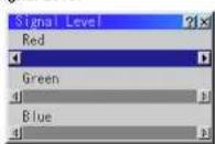

R/G/B, Y/Cb/Cr or Y/Pb/Pr Gain:
Adjust RGB, Component or HDTV Gain to match multiple projector color uniformity.
Image
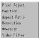
Horizontal/Vertical Position (when Auto Adjust is off):

Adjusts the image location from left to right.
This adjustment is made automatically when the Auto Adjust is turned on.
Aspect Ratio (not available for RGB):
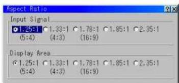
You can select the aspect ratio for input signal and display area respectively.
Select the appropriate aspect ratio using the SELECT ◀, ▶, ▲, or ▼ button.
NOTE: When "Resolution" is set to "Native", this feature is not available, and the stored settings and adjustments are invalid.
Resolution (when Auto Adjust is off):
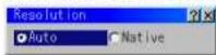
This allows you to activate or deactivate the Advanced AccuBlend feature.
Auto ....Turns on the Advanced AccuBlend feature. The projector automatically reduces or enlarges the current image to fit the full screen.
Native.....Turns off the Advanced AccuBlend feature. The projector dis-
Video Filter
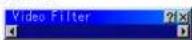
This feature reduces video noise. Select the appropriate filter for your signal.
Bar 0....Off
Bar 1/3 ...... High
Bar 2/3 ...... Medium
Bar full .... Low
Blanking

This feature allows you to mask any unwanted area of the screen image.
Blanking On/Off:
This setting enables or disables the blanking function.
On .... Blanking function is enabled.
Off...... Blanking function is disabled.
* Adjustment of vertical display range
Adjust the Top, Bottom, Left or Right blanking with the SELECT◀ or ▶ button.
Video Adj
Noise Reduction
Color Matrix
Color Matrix

First, select an appropriate color matrix for your input signal, either HDTV or SDTV. Then select an appropriate matrix type from B-Y/R-Y, Cb/Cr, Pb/Pr or IVX.
NOTE: The Color Matrix feature is available for component video signal only.
Y/C Delay (not available for RGB)
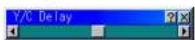
Adjusts Y/C delay level.
Telecine
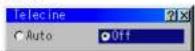
Use 3:2 pull down correction to eliminate jitter and artifacts in video.
Auto ...... For film source such as a DVD player
Off..... For signals other than film sources
Motion Select:

Sets the interpolation method. Selects Still or Adaptive. Still is used for non moving images such as a document camera. Select Adapter for all motion video.
Motion Level
Option Adj
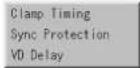
Clamp Timing:
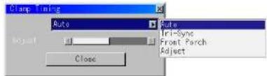
According to the signal, this function sets the detection position (i.e., clamp position) of the black level reproduction of the analog input signal. Normally this is not used. (1080P is set as the default)
Auto ...... This is the normal setting.
Tri-Sync ..... This is set when projecting HDTV video.
Front Porch ... This is set when the picture quality does not improve even though Auto or Tri-Sync has been set.
Adjust .... This permits the video clamp position for each signal to be set. Use "Adjust" when a clamp timing error occurs at the time of special analog signal reception such as 1080P. Note that "Adjust" is not valid for doubler signals such as NTSC and PAL.
To delete the "Clamp Timing" setting screen, select the SELECT button and press the ENTER button, or press the remote control CANCEL button.
Sync Protection

When a VCR, DVD, or some other equipment that supports Copyguard (a copy prevention system) is played back, the screen may be displayed in a curved manner. Adjustments are made in such circumstances. Use the SELECT ◀ or ▶ button to adjust the VD level.
Switcher (available only when used with ISS-6020)
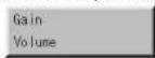
Switcher Gain

This feature adjusts the input level of the signal. This must be done to each color: R, G, and B.
Switcher Volume

This feature adjusts the volume of the audio output. Adjust the sound corresponding to the slot.
Volume
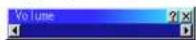
Adjusts the sound level of the projector.
NOTE: You can also display the volume bar without opening the menu. See "Volume Bar (Direct Button)" on page E-48 for more details.
Ref Adj

Keystone
NOTE:
1) With the projector aimed directly at the screen the maximum keystone angle that can be corrected is +/-30 degrees for RGB signal and +/-15 degrees for the other signals.
2) When "Resolution" is set to "Native", this feature is not available, and the stored settings and adjustments are invalid.
Depending on the type of graphics being used. the picture may get blurred or keystone correction may not be possible when excessive keystone correction is used.
The idea is, the closer you are to native resolution, the better image you will
NOTE: The keystone feature is not available when the test pattern or the blue back is displayed.
Lamp Mode

This feature enables you to select two brightness mode of the lamp: Normal and Eco modes. The lamp life can be extended up to 2000 hours by using the Eco mode.
Normal Mode ....This is the default setting. Eco Mode....Select this mode to increase the lamp life.
NOTE: If you have selected the Eco mode, the lamp lights in Normal mode for 3 minutes after the projector is turned on. After 3 minutes the lamp will change to Eco mode.
Reference White Balance
This feature adjusts the white balance that is used as a reference. This adjustment affects all sources. The Ref. White Bal. is available for test pattern only.
Factory Default

Projector Options

Enables you to set preferences and other operating options.
Timer
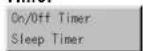
Enables you to turn on or off your projector automatically at a specified time. Two timer functions are available: On/Off Timer and Sleep Timer.
On/Off Timer

Up to eight settings can be programmed.
- Before setting On/Off Timer, make sure that Date, Time Preset feature is set.
-
Even after setting On/Off Timer, turning the projector on or off with the remote control is possible.
-
To enable your setting, select Active on the Execute Switch.
- Select OK and press the ENTER button on the remote control to complete the setting.
NOTE: When On Timer is set and the projector is in the standby mode, the Status indicator flashes green to show that On Timer program is active. The projector must be in stand-by mode at the time of turning on. The preset power-on time will be void if the cooling fan is working or an error occurs. Unplugging the projector cancels your 1 Week programs regardless of whether the program was executed or not. However, your Every Week program will not be cancelled even if you unplug the projector.
Sleep Timer

- Select your desired time between 30 minutes and 2 hours in 30 minute increments.
- Select Sat and press the ENTER button on the remote control.
- The remaining time starts counting down.
- The projector will turn off after the countdown is complete.
Menu
[Page 1]

Allows you to set preferences for the on-screen menu. Press "OK" to save your changes for all the features.
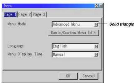
Menu Mode:
This feature allows you to select two menu modes: Advanced Menu and Basic/Custom Menu.
Advanced Menu ....This is the menu that contains all the available menus and commands. Basic/Custom Menu....This is the menu that you can customize using the Basic/Custom Menu Edit to fit your needs.
The factory default Basic/Custom menu includes: Source Select (RGB1/2, DVI DIGITAL, Videoc1/2, S-Video and Entry List), Brightness, Contrast, Pixel Adjust and Position. See page E-36 for instructions about how to customize the Basic/Custom Menu.
Language:
You can choose one of seven languages for on-screen instructions. The options are: English, German, French, Italian, Spanish, Swedish and Japanese.
Menu Display Time :
This option allows you to select how long the projector waits after the last touch of a button to turn off the menu. The preset choices are "Manual", "Auto 5 sec", "Auto 10 sec", and
[Page 2]
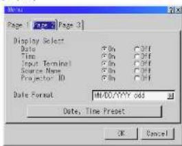
Display Select:
You can choose the desired status information to be displayed on the screen. The desired status information will be displayed each time you switch between sources.
Date Format:
Eight display formats can be selected. This date format sets the current date that appears on the upper left corner of the screen.
Date, Time Preset:

Setting the Current Date and Time
You can set the current time, month, date, and year.
- Type in date.
Enter month, date and year in this order using INPUT buttons on the
remote control
Month and date must be entered in two digits. For example, to display
February, press 0" and 2"
[Page 3]

Message:
You can choose the desired information to be displayed on the screen.
No Input: This option turns on or off the "No Input" message to be displayed in the top right corner on the screen.
On .... The message will be displayed.
Off..... The message will not be displayed.
Clean Filter: This option turns on or off the 'Please clean the filters' message each time you turn on the projector if the projector has been used in excess of 100 hours of use.
On .... The message to clean the filters will be displayed.
Off..... The message will not be displayed.
See page E-53 for cleaning the filters. After cleaning the filters, reset the filter usage back to zero.
To reset the filter usage, see page E-50.
Direct Button:
Volume Bar: This option turns on or off the volume bar when you adjust the sound volume using Select ▲▼ button on the remote control.
On .... You can increase or decrease the sound volume with the volume bar on screen.
Off .... You can increase or decrease the sound volume without having to use the volume bar.
Keystone Bar: This option is available on the optional remote control only. This option turns on or off the keystone bar when you adjust the
Orientation
This reorients your image for your type of projection.
The options are: desktop front projection, ceiling rear projection, desktop rear projection, and ceiling front projection.
Background
Use this feature to display a blue/ black screen or logo when no signal is available. The default background is blue.
S-Video Mode Select
This feature is used to select the S-Video signal detection mode. This allows identifying of the S-Video signals with different aspect ratio (Zoom signal 16:9, Wide Zoom signal 4:3).
S2.... Identifies Zoom or Wide Zoom signal.
OFF.... Does not identify any S-video signal.
Remote Sensor
This option determines which remote sensors on the projector are enabled in wireless mode. The options are: front, rear, right, or left. All checked boxes indicate that they can accept the infrared signal from the remote control.
[Page 2]

Signal Select (RGB1/2)
Allows you to choose "RGB" for an RGB source such as a computer, or "Component" for a component video source such as a DVD server. Normally selected "Local" and the monitor is clearly called
[Page 3]

Signal Select (VIDEO 1/2 and S-VIDEO)
This feature enables you to select composite video standards manually. Normally select "Auto". Select the video standard from the pull-down menu. This must be done for Video and S-Video separately.
Signal Select (RGB Connector)
Allows you to choose "VIDEO" or "S-VIDEO" for RGB1 connector. Normally select "Auto".
[Page 4]

Auto Adjust (RGB Only)
Power Management
When this option is on and there is no RGB input for five minutes or more, the projector will automatically turn itself off.
Power Off Confirmation
This option determines whether a confirmation dialog for turning off the projector will appear or not.
Keystone Save
This option enables you to save your current keystone settings. Saving your change once affects all sources. The changes are saved when you turn off the projector.
Built-in Speaker
This option allows you to activate the built-in speakers when you connect an audio cable to the AUDIO OUT terminal.
Lamp Off Mode
Turning on this option allows a signal to be passed through to the Monitor Output connector during standby condition. This is available for an RGB signal only.
Last Memory
The projector stores the last signal data in memory for each input (RGB1, RGB2, DVI DIGITAL, Video, and S-Video). This feature will reduce switching time between sources. If a commercially available switcher is connected, turning on this feature may cause the image to appear incorrectly. Should this happen, turn this feature off to mute the screen during switching. Normally if this feature is turned on when the projector is used in standalone mode, switching time between sources will be shortened.
User Name
Type in your desired name using the INPUT buttons on the remote control. Select one character at a time with the INPUT buttons 1 through 10(0) and by moving the cursor with the SELECT button. The user name must be 18 characters or less. Only after completely finishing the selection of the characters, press ENTER.
Projector ID
Each projector needs its own unique addresses when used in serial communication mode. You can choose one of 64 unique address using the spin box. First select Enable. Keep pressing button increases the number. To make your setting available, select OK.
Default Source Select
You can set the projector to default to any one of its inputs each time the projector is turned on.
Last.... Sets the projector to default to the previous or last active input each time the projector is turned on. Auto.... Searches for an active source in order of RGB1 → RGB2 → DV1 DIGITAL → Video 1 → Video 2 → S-Video → RGB1(Standalone) and displays the first found source. Searching order in SW1 Level: from Slot 1 to 10. Searching order in SW2 Level: from Master projector 01, Slave projector 01 to Master projector 10, Slave projector 10 Select.... Displays the selected source input every time the projector is started up. Select an input from the pull-down menu.
[Page 6]

Resets the lamp clock back to zero. Pressing this button appears a confirmation dialog box. To reset the lamp usage hour, press "OK". NOTE: The projector will turn off and go into standby mode after 1600 hours (up to 2100 hours in Eco mode) of service. If this happens, press the "Help" button on the remote control for 10 seconds to reset the lamp clock back to
Switcher Control

This feature sets the projector in communication with the NEC ISS-6020 Switchers.
Stand Alone ....Use the projector in stand alone operation.
SW 1 Level.....Use the projector with one Switcher. (not available in Link mode)
SW 2 Level.....Use the projector with two or more Switchers. (not available in Link mode)

When changing this setting, the confirmation message will appear. If you want to restart your projector, select Yes; if not, select No.
NOTE: This setting becomes effective only after the projector is restarted.
Help

Contents
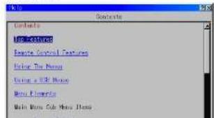
Projector Information
![Projector Information Page | Page 2 | Page 3 | Page 4 | User Name Set User Name Remaining Lamp Time 100% Lamp Hour Meter 00000 [F] Filter Usage 00000 [F] Projector Usage 00000 [F] Projector ID None](/content/2026/06/1247287/images/ffd0f3e3161e80f1c6bcbb18b1b9f0b2d744dc9c5215113f0e42b37d87a70111.jpg)
Displays the information for your projector such as lamp usage, serial number and version number etc..
[Page 4]
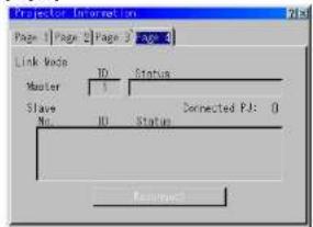
Link Mode
Displaying Current Status of Link Mode When selecting the tab "Page 4", you will get the following dialog box.
Master ID....Indicates the Master projector Status....Indicates the status of the master projector Connected PJ....Indicates number of connected slave projectors Slave No....Indicates serial number of the slave projector ID....Indicates ID of a slave projector
6. MAINTENANCE
This section describes the simple maintenance procedures you should follow to replace the lamp and clean the filter.
Replacing the Lamp
After your lamp has been operating for 1500 hours (2000 hours : Eco mode) or longer, the "Status" indicator in the cabinet will go on and the message will appear. Even though the lamp may still be working, replace it at 1500 (up to 2000 hours : Eco mode) hours to maintain optimal projector performance.
CAUTION
- DO NOT TOUCH THE LAMP immediately after it has been used. It will be extremely hot. Turn the projector off, wait three minutes, and then disconnect the power cable. Allow at least one hour for the lamp to cool before handling.
- DO NOT REMOVE ANY SCREWS except the lamp cover screw and two lamp housing screws. You could receive an electric shock.
• The projector will turn off and go into stand by mode after 1600 (2100 hours: Eco mode) hours of service. If this happens, be sure to replace the lamp. If you continue to use the lamp after 1500 hours (2000 hours: Eco mode) of use, the lamp bulb may shatter, and pieces of glass may be scattered in the lamp housing. Do not touch them as the pieces of glass may cause injury. If this happens, contact your NEC dealer for lamp replacement.
To replace the lamp:
- Loosen the lamp cover screw until the screwdriver goes into a freewheeling condition and remove the lamp cover. The lamp cover screw is not removable.
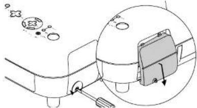
natural_image
Diagram showing a mechanical component with an inset close-up of a device (no text or symbols present)- Insert a new lamp housing until the lamp housing is plugged into the socket.
CAUTION: Do not use a lamp other than the NEC replacement lamp (GT50LP). Order this from your NEC dealer.
Secure it in place with the two screws. Be sure to tighten the screws.

natural_image
Technical line drawing of a mechanical assembly with an inset close-up showing a bracket and circular components (no text or symbols)- Reattach the lamp cover.
Tighten the lamp cover screw. Be sure to tighten the screw.

Cleaning or Replacing the Filter
The air-filter sponge keeps the inside of the MultiSync GT2150 Projector free from dust or dirt and should be cleaned after every 100 hours of operation (more often in dusty conditions). If the filter is dirty or clogged, your projector may overheat.
CAUTION
- Turn off the power, wait for three minutes, and unplug the projector
before replacing the filter. - Only clean the outside of the filter with a vacuum cleaner.
- Do not attempt to operate the projector without filter.
- Your projector will not operate unless the filter is installed correctly.
To clean the filter:
Pull out the filter by pushing up on the catch. Vacuum the filter-through the filter.

The "Please clean the filters" message will be displayed each time the projector is turned on after it has been used in excess of 100 hours. Should this message appear, clean the filters.
NOTE:
* The message can be turned on or off using the "Message" - "Clean Filter" option on the Setup menu. See page E-48.
* After cleaning the filters and resetting the filter usage time back to zero, the message will not be displayed.
See page E-50 for resetting the filter usage time.
To replace the filter:
- Pull out the filter by pushing up on the catch.
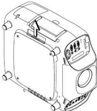
natural_image
Technical line drawing of a mechanical device with no visible text or symbols
natural_image
Line drawing of a car interior panel with a ventilation grille and control knobs (no text or symbols)natural_image
Diagram showing a mechanical component with an inset close-up of its internal structure (no text or symbols)natural_image
Technical diagram of a mechanical device with an inset showing internal components (no text or symbols)natural_image
Simple line drawing of a mechanical device with a magnified inset showing a component (no text or symbols)The "Please clean the filters" message will be displayed each time the projector is turned on after it has been used in excess of 100 hours. Should this message appear, clean the filters.
REMARQUE:
natural_image
Technical line drawing of a mechanical device with no visible text or symbols
natural_image
Technical line drawing of a mechanical device with a ventilation grille and control panel (no text or symbols)7. TROUBLESHOOTING
This section helps you resolve problems you may encounter while setting up or using the projector.
Power/ Status Light Messages
| Condition | Power Indicator | Status Indicator | Note | |
| Standby Normal | Steady orange | - | - | |
| ON-Timer setting | Steady orange | Blinking green (4 sec interval) | ||
| Cooling down | Blinking green | - | Blinks green for 60 seconds | |
| Lamp in Normal mode | Steady green | - | - | |
| Lamp in Eco mode | Steady green | Steady green | - | |
| 9 minutes after lamp is turned on in Eco mode | Steady green | Blinking green | Fixed at Normal mode. Lamp mode can be changed on the menu | |
| Lamp has reached its end of life (1500 hours or over) | Steady green | Steady red (Normal mode)/ Steady orange (Eco mode) | Message appears on screen during 1500-1600 hours of lamp usage. The projector reaches its end of life. Please replace the lamp as soon as possible. | |
| Lamp life has reached its end of life (1600 hours or over) | Steady orange | Steady red | The projector is in standby mode and cannot be turned on. | |
| Lamp cover, filter cover or lens holder error (3 locations) | Steady orange | Blinking red (1 sec interval) | The projector is in standby mode and cannot be turned on. | |
| Temperature error | Steady orange | Blinking red (4 sec interval) | The projector is in standby mode and cannot be turned on. | |
| Fan error | Steady orange | Blinking red (8 sec interval) | The projector is in standby mode and cannot be turned on. | |
| Lamp error | Steady orange | Blinking red (12 sec interval) | The projector is in standby mode and cannot be turned on. | |
Lamp Light Messages
| Lamp Remaining Time | Indicator |
| 100 – 50% | Steady green |
| 50 – 25% | Steady orange |
| 25 – 0% | Steady red |
Common Problems & Solutions
| Problem Check These Items | |
| Does not turn on | • Check that the power cable is plugged in and that the power button on the projector cabinet or the remote |
8. SPECIFICATIONS
This section provides technical information about the GT2150 Projector's performance.
Model Number GT2150
Optical
LCD Panel 1.3" p-Si TFT active-matrix with Micro Lens Array, 1366×1024 native resolution up to 1600×1200 with Advanced AccuBlend Technology
Lamp 250 W NSH lamp
Lamp Life Eco-mode 2000 hours/Normal mode 1500 hours
The lamp, under normal operating conditions, is warranted for 1500 hours of operation time within 6 months.
Lens Options Motorized zoom (except GT10RL lens) and Motorized focus
GT19ZL : F2.0-2.5 f-48.9-63.7mm
GT13ZL : F2.3-2.8 f=34.5-42.5mm
GT34ZL : F2.5-3.4 I=92.4-140.6mm
GT10RL : F2.3 f=27mm
Lens Shift Vertical +/- 0.5V
(GT19ZL and GT34ZL) Horizontal +/- 0.25H
Image Size GT19ZL/GT13ZL/GT10RL: 40 - 300 inches (1016 - 7620 mm) diagonal
GT34ZL : 80-500 inches (2032-12700 mm) diagonal
Projection Distance GT19ZL lens : 4.8 - 48.0 ft (1.5 - 14.6 m)
GT10RL lens : 2.7-20.0 ft (0.8m-6.1m)
GT13ZL lens : 3.5-32.0 ft (1.1m-9.Bm)
GT34ZL lens : 18.1-173.2 ft (5.5m-52.8m )
Projection Angle GT19ZL: -9.0 degree (tele) / 11.7 degree (wide)
GT13ZL: -13.3 degree (tele) / 16.4 degree (wide)
GT34ZL: -4.0 degree (tele) / 6.2 degree (wide)
Electrical
Input Connections
RGB/YCr/Cb/H(HV)V 5 BNC×1, RCA (L/MONO, R)×1
RGB D-Sub 15 pin × 1, RCA (L/MONO, R) × 1
DVI DIGITAL DVI-D (Max resolution : SXGA@60Hz) x 1. RCA (L/MONO, R) x 1
Video BNC×1, RCA×1, RCA (L/MONO, R)×1
S-Video Mini DIN 4×1, RCA (L/MONO, R)×1
PC Card Slot×
RGB DVI-D×1, D-Sub 15 pin×1, RCA (L/MONO, R)×1
Mechanical
Dimensions 16.5" (W) × 7.7" (H) × 19.4" (D) / 419 mm (W) × 195 mm (H) × 494 mm (D) (not including feet)
Net Weight 28.3 lbs / 12.8 kg (not including lens)
Environment Operational Temperatures: 32° - 95°F (0° to 35°C), 20 - 80% humidity
Storage Temperatures: 14° - 122°F (-10° to 50°C), 20 - 80% humidity
Regulations UL Approved (UL 1950, CSA 950)
Meets DOC Canada Class B requirements
Meets FCC Class B requirements
Meets AS/NZS3548 Class B
Meets EMC Directive (EN55022, EN55024, EN61000-3-2, EN61000-3-3)
Meets Low Voltage Directive (EN60950. TUV GS Approved)
CE
LCD panels are inherently susceptible to bad pixels. The LCD panel may have pixel failures at the rate of 0.01% or less.
We provide information about our projectors through the World Wide Web at http://www.nec-pj.com/
The specifications are subject to change without notice.
9. Appendix
Cabinet Dimensions
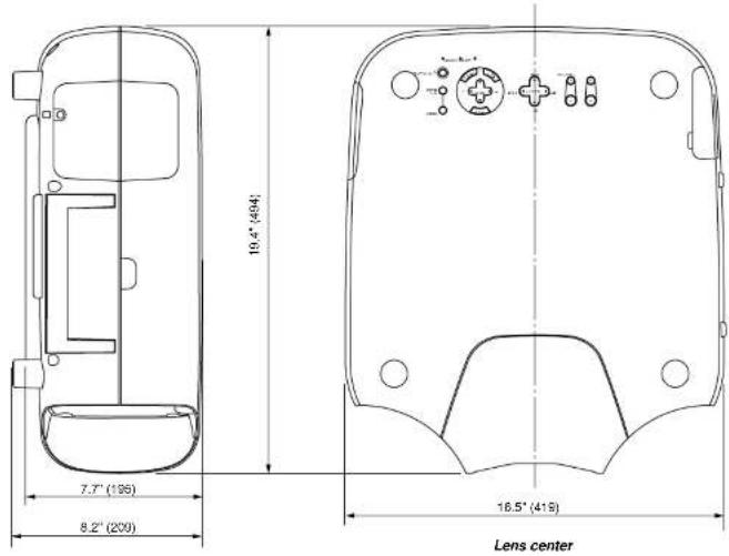
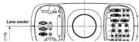
D-Sub Pin Assignments
Mini D-Sub 15 Pin Connector (RGB2)
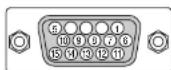
Signal Level
^4 Vibieb signal : 0.7Vp-p (Analog)
Sync signal : TTL level
| Pin No. | RGB Signal (Analog) YCbCr Signal | |
| 1 | Red Cr | |
| 2 | Green or Sync on Green Y | |
| 3 | B I u e C b | |
| 4 | Ground | |
| 5 | Ground | |
| 6 | Red Ground Cr Ground | |
| 7 | Green Ground Y Ground | |
| 8 | Blue Ground Cb Ground | |
| 9 | No Connection | |
| 10 | Sync Signal Ground | |
| 11 | Ground | |
| 12 | Bi-directional DATA (SDA) | |
| 13 | Horizontal Sync or Composite Sync | |
| 14 | Vertical Sync |
Compatible Input Signal List
| Signal Name Resolution (H×V) | Horizontal Frequency Vertical Frequency | ||
| Video (NTSC) | 640 × 480 | 15.734 | 60.0 |
| Video (PAL/SECAM) | 768 × 576 | 15.625 | 50.0 |
| Video (HDTV) | 640 × 480p | 31.5 | 60.0 |
| 1280 × 720p | 45.0 | 60.0 | |
| 1920 × 1035i | 33.75 | 60.0 | |
| 1920 × 1080i | 28.13 | 50.0 | |
| 1920 × 1080i | 33.75 | 60.0 | |
| IBM PC or Compatibles | 640 × 350 | 31.5 | 70.0 |
| 640 × 400 | 37.9 | 85.0 | |
| 720 × 400 | 37.0 | 85.0 | |
| 640 × 480 | 31.5 | 60.0 | |
| 640 × 480 | 37.9 | 72.8 | |
| 640 × 480 | 37.5 | 75.0 | |
| 640 × 480 | 43.3 | 85.0 | |
| 800 × 600 | 35.2 | 56.3 | |
| 800 × 600 | 37.9 | 60.3 | |
| 800 × 600 | 48.1 | 72.0 | |
| 800 × 600 | 46.9 | 75.0 | |
| 800 × 600 | 53.7 | 85.0 | |
| 1024 × 768 | 49.4 | 60.0 | |
| 1024 × 768 | 56.5 | 70.1 | |
| 1024 × 768 | 60.0 | 75.0 | |
| 1024 × 768 | 68.7 | 85.0 | |
| 1152 × 864 | 67.5 | 75.0 | |
| 1280 × 960 | 60.0 | 60.0 | |
| 1280 × 1024 | 64.3 | 60.0 | |
| 1280 × 1024 | 80.0 | 75.0 | |
| 1280 × 1024 | 91.1 | 85.0 | |
| 1600 × 1200 | 75.0 | 60.0 | |
| 1600 × 1200 | 81.3 | 65.0 | |
| 1600 × 1200 | 87.5 | 70.0 | |
| 1600 × 1200 | 93.8 | 75.0 | |
| 1600 × 1200 | 102.2 | 87.5 | |
List of Menu Items Available on Link Mode
See the table below for available functions in the digital link mode and the analog link mode.
| Function Link mode | ||||
| Menu Source | Select L | |||
| Adjust(Source) Picture | Brightness L | |||
| Contrast L | ||||
| The others N | ||||
| White Balance N | ||||
| Image Pixel Adjust | L(Phase) | |||
| Position L | ||||
| The others N | ||||
| Video Adj N | ||||
| Option Adj N | ||||
| Signal Type | N | |||
| Switcher | N | |||
| Volume | M | |||
| Ref Adj | Keystone | N | ||
| Lamp Mode | N | |||
| Ref. White Bal. | N | |||
| Factory Default | N | |||
| Projector Options | Timer | L | ||
| Menu | M | |||
| Setup | N | |||
| Link Mode M | ||||
| Switcher Control | N | |||
| LAN Mode | N | |||
| Help | M | |||
| Test Pattern | N | |||
| Direct Button | LENS SHIFT | Projector | I | |
| Remote Control | N | |||
| FOUCUS | Projector | I | ||
| Remote Control | I | |||
| ZOOM Projector | I | |||
| Remote Control | I | |||
| MENU | Projector | L (*1) | ||
| Remote Control | L (*1) | |||
| POWER | Projector | L (*2) | ||
| POWER ON | Remote Control | L (*2) | ||
PC Control Codes
| Function Code Data | ||||||
| POWER ON 02H 00H 00H 00H 00H 02H | ||||||
| POWER OFF 02H 01H 00H 00H 00H 03H | ||||||
| INPUT SELECT RGB 1 02H 03H 00H 00H 02H 01H 01H 09H | ||||||
| INPUT SELECT RGB 2 02H 03H 00H 00H 02H 01H 02H 0AH | ||||||
| INPUT SELECT VIDEO 1 | 02H 03H 00H 00H 02H 01H 06H 0EH | |||||
| INPUT SELECT VIDEO 2 | 02H 03H 00H 00H 02H 01H 07H 0FH | |||||
| INPUT SELECT S-VIDEO | 02H 03H 00H 00H 02H 01H 08H 13H | |||||
| INPUT SELECT DVI (DIGITAL) 02H 03H 00H 00H 02H 01H 1AH 22H | ||||||
| PICTURE MUTE ON | 02H 10H 00H 00H 00H 12H | |||||
| PICTURE MUTE OFF | 02H 11H 00H 00H 00H 13H | |||||
| SOUND MUTE ON | 02H 12H 00H 00H 00H 14H | |||||
| SOUND MUTE OFF 02H 13H 00H 00H 00H 15H | ||||||
| ON SCREEN MUTE ON | 02H 14H 00H 00H 00H 16H | |||||
| ON SCREEN MUTE OFF | 02H 15H 00H 00H 00H 17H | |||||
NOTE: Contact your local dealer for a full list of the PC Control Codes if needed.
Cable Connection
| Communication Protocol |
| Baud rate: 38400 bps |
| Data length: 8 bits |
| Parity: No parity |
| Stop bit: One bit |
| X on/off: None |
| Communications Full duplex procedure: |

NOTE: Pins 1, 4, 6 and 9 are used inside the projector. NOTE:: Jumper "Request to Send" and "Clear to Send" together on both ends of the cable to simplify cable connection.
Gravity Stack
Up to two units can be gravity stacked without external support. In some cases, however, two images will not align on the screen correctly. This will become more apparent when displaying small text and detailed graphics.
1. Note : Gravity Stacking Two GT2150 Projectors
The optional lenses for GT2150 have different geometrical distortions in wide zoom and tele. Select the best zoom position for stacking where the geometrical distortion is as small as possible. The recommended throw distances are as follows:
- CAUTION
- RF Interference
- WARNING
- INFORMATIONS IMPORTANTES
- Précautions
- Important Safeguards
- Installation
- To Dealer or Installer:
- Power Supply
- Cleaning
- Lamp Replacement
- Fire and Shock Precautions
- LIMITED WARRANTY (USA and Canada only)
- NEC TECHNOLOGIES' PROJECTOR PRODUCTS
- HOW LONG IS THE WARRANTY
- WHO IS PROTECTED
- WHAT IS COVERED AND WHAT IS NOT COVERED
- LIMITATION OF IMPLIED WARRANTIES
- EXCLUSION OF DAMAGES
- HOW STATE LAW RELATES TO THE WARRANTY
- TABLE OF CONTENTS
- INTRODUCTION
- INSTALLATION
- Basic Operation
- CONNECTIONS
- OPERATION
- INTRODUCTION
- What's in the Box?
- Attaching the lens hood cap to the lens hood with the supplied string and rivet
- Top Features
- Power Button (ON / STAND BY) (○)
- Auto Adjust Button (RGB only)
- Source Button
- Lens Shift Button
- Zoom Button
- Focus Button
- Lamp Remaining Indicator
- Status Indicator
- Inserting or Ejecting a CompactFlash Card
- POWER ON
- POWER OFF
- MENU
- ENTER
- Select (Up/Down/Left/Right)
- ADJUST WHITE BAL
- ADJUST PICTURE
- UNDO
- CANCEL
- INFO
- TEST
- HELP
- PIXEL
- AUTO (RGB only)
- POSITION
- MUTE SOUND
- MUTE OSD
- FOCUS (+/-)
- MAGNIFY/ZOOM (+/-)
- CTL
- Remote Jack
- Infrared Transmitter
- Remote Control Precautions
- Remote Control Battery Installation
- Operating Range for Wireless Remote Control
- Using the Remote Control in Wired Operation
- INSTALLATION
- Setting Up Your GT2150 Projector
- Lens Shift Adjustable Range
- Optional Lens Installation
- Before installation
- Preparation: Tools needed for installation:
- 1) Stacking the Projectors
- 6) Link Mode Setting
- Projector Orientation
- Ceiling Front Projection
- Ceiling Rear Projection
- Desktop Rear Projection
- BASIC OPERATION
- Connecting the Power Cable and Turn on the Projector
- To turn off the projector:
- About Startup Screen
- Set up the projector
- Other adjustments
- CONNECTIONS
- When used in standalone operation
- Connecting Your VCR Or Laser Disc Player
- Connecting Your DVD Player with Component Output
- Connecting Your PC Or Macintosh Computer
- Connecting a PC with DVI output
- Using OUTPUT Connectors
- Connecting to a Single Workstation
- When Used with One Switcher (ISS-6020/ISS-6020G)
- When Used with Two or More Switchers (100 Inputs)
- How to make connections:
- NOTE:
- REMOTE 1 Connector
- Pin Configuration of Optional CTL-6010 Cable
- Operating Multiple Projector with Remote Control
- Using the PC CONTROL connectors
- OPERATION
- General Controls
- Turn on the Projector
- Select The Computer Or Video Source
- Adjust The Image
- Turn Off The Projector
- IMPORTANT:
- Using the Menus
- Customizing Basic/Custom Menu
- The default Basic/Custom Menu Items are:
- Menu tree
- Menu Descriptions & Functions Source Select
- Swicher
- Entry List
- Entry Edil Command
- Selecting a new signal that is close to one of the listed signals in horizontal and vertical frequency
- Color
- Hue
- Sharpness
- V-Aperture
- Gamma Correction
- White Balance
- Color Temperature
- Brightness
- Contrast
- Signal Level
- Image
- Horizontal/Vertical Position (when Auto Adjust is off):
- Aspect Ratio (not available for RGB):
- Resolution (when Auto Adjust is off):
- Video Filter
- Blanking
- Video Adj
- Color Matrix
- Y/C Delay (not available for RGB)
- Telecine
- Motion Select:
- Motion Level
- Option Adj
- Clamp Timing:
- Sync Protection
- Switcher (available only when used with ISS-6020)
- Switcher Gain
- Switcher Volume
- Volume
- Ref Adj
- Keystone
- Lamp Mode
- Reference White Balance
- Factory Default
- Projector Options
- Timer
- On/Off Timer
- Sleep Timer
- Menu
- [Page 1]
- Menu Mode:
- Language:
- Menu Display Time :
- Display Select:
- Date Format:
- Setting the Current Date and Time
- Message:
- Direct Button:
- Orientation
- Background
- S-Video Mode Select
- Remote Sensor
- Signal Select (RGB1/2)
- Signal Select (VIDEO 1/2 and S-VIDEO)
- Signal Select (RGB Connector)
- Power Management
- Power Off Confirmation
- Keystone Save
- Built-in Speaker
- Lamp Off Mode
- Last Memory
- User Name
- Projector ID
- Default Source Select
- [Page 6]
- Switcher Control
- Help
- Contents
- Projector Information
- [Page 4]
- Link Mode
- MAINTENANCE
- Replacing the Lamp
- To replace the lamp:
- Cleaning or Replacing the Filter
- To clean the filter:
- To replace the filter:
- REMARQUE:
- TROUBLESHOOTING
- SPECIFICATIONS
- Model Number GT2150
- Optical
- Electrical
- Mechanical
- CE
- Appendix
- D-Sub Pin Assignments
- Mini D-Sub 15 Pin Connector (RGB2)
- List of Menu Items Available on Link Mode
- Gravity Stack
- Note : Gravity Stacking Two GT2150 Projectors
Brand : NEC
Model : GT2150
Category : Video projector