
KRF-V6200D - Audio/Video Receiver KENWOOD - Free user manual and instructions
Find the device manual for free KRF-V6200D KENWOOD in PDF.
Download the instructions for your Audio/Video Receiver in PDF format for free! Find your manual KRF-V6200D - KENWOOD and take your electronic device back in hand. On this page are published all the documents necessary for the use of your device. KRF-V6200D by KENWOOD.
USER MANUAL KRF-V6200D KENWOOD
Before applying power À\ cautio: operation. Read this page carefully to ensure safe Units are designed for operation as follows. Australia Europe. AC 240 V only AC 230 Vonly Information on Disposal of Old Electrical and Electronic Equipment (applicable for EU countries that have adopted separate waste collection systems) Products with the symbol (crossed-out wheeled bin) cannot be disposed as household waste. em Old electrical and electronic equipment should be recycled at a facility capable of handling these items and their waste by products. Contact your local authority for details in locating a recycle facility nearest to you. Proper recycling and waste disposal will help conserve resources whilst preventing detrimental effects on our health and the environment. Safety precautions
LITERATURE ACCOMPANYING THE APPLIANCE. û THE EXCLAMATION POINT WITHIN AN EQUILATERAL 2 Engtish B60-5678-00_OOindd 2 DA Unpacking Unpack the unit carefully and make sure that all the accessories are present. FMindoor antenna (1) AM loop antenna (1) Remote control unit (1) Batteries (RO3) (2) RC-RO732 If any accessories are missing, or ifthe unit is damaged or fails to operate, notify your dealer immediately. If the unit was shipped to you directly, notify your shipper immediately. Kenwood recommends that you retain the original carton and packing materials in case you need to move or ship the unit in the future. Keep this manual handy for future reference. Notes oninstructions The operating instructions given in this manual assume that the user mainly operates the receiver using the remote control unit. When the same operation is also available on the main unit, the operating method is indicated in illustrations. The [VOLUME CONTROL], [MULTI CONTROL] and [INPUT SELECTOR] knobs on the main unit are operated by tuning the knobs clockwise or counterclockwise. Example: Getting into the setup mode
The knob on the main unit + is pointed with an arrow to indicate that it can be turned in “either direction. The operating procedures refer to those of the remote 80 serup control unit. Some el muin conrroL operations are also ù av available using the key {or knob) ofthe same name on the main unit. A Use [MULTI CONTROL A/v] EdPress (SETUP) t iect the element to setup. spy Sein SUP Sep STONE line DS Dane tu PT . EXT Bitte setup mode. u Options to be El Press ISETUP]to getintothe setup mode ofthe selected are listed selected element in a table.
À Caution : Read this page carefully to ensure safe operation. Read Instructions — All the safety and operating instructions should be read before the product is operated. Retain Instructions - The safety and operating instructions should be retained for future reference. Heed Warnings — All warnings on the product and in the operating instructions should be adhered to. Follow Instructions - All operating and use instructions should be followed.
1. Cleaning - Unplug this product from the wall outlet before
cleaning. Do not use liquid cleaners or aerosol cleaners. Use à damp cloth for cleaning.
2. Attachments - Do not use attachments not recommended by
the product manufacturer as they may cause hazards. Water and Moisture - This product shall not be exposed to dripping and splashing - for example, near a bath tub, wash bowil, kitchen sink, or laundry tub; in a wet basement:; or near a swimming pool and the like. Do not place an object containing liquid, such as a flower vase, on the appliance.
4. Accessories - Do not place this product on an
unstable cart, stand, tripod, bracket, or table. The product may fall, causing serious injury to a child or adult, and serious damage to the product. Use only with a cart, stand, tripod, bracket, or table recommended by the manufacturer. Any mounting of the product should follow the manufacturer's instructions, and should use a mounting accessory recommended by the manufacturer. À product and cart combination should be moved with care. Quick stops, excessive force, and uneven surfaces may cause the product and cart combination to overturn.
5. Ventilation - Slots and openings in the cabinet are provided for
ventilation and to ensure reliable operation of the product and to protect it from overheating, and these openings must not be blocked or covered. The openings should never be blocked by placing the product on a bed, sofa, rug, or other similar surface. This product should not be placed in a built-in installation such as a bookcase or rack unless proper ventilation is provided or the manufacturer instructions have been adhered to.
6. Power Sources - This product should be operated only from the
type of power source indicated on the product. f you are not sure of the type of power supply to your home, consult your product dealer or local power company.
7. CAUTION_ poiarization - This product may be equipped
with a polarized alternating-current line plug (a plug having one blade wider than the other). This plug will fit into the power outlet only one way. This is a safety feature. If you are unable to insert the plug fully into the outet, try reversing the plug. the plug should stil fai to ft, contact your electrician to replace your obsolete outet. Do not defeat the safety purpose ofthe polarized plug
8. Power Cord Protection - Power-supply cords should be routed
so that they are not likely to be walked on or pinched by items placed upon or against them, paying particular attention to cord at plugs, convenience receptacles, and the point where they exit from the product.
9. Lightning - For added protection for this product during a
lightning storm, or when it is left unattended and unused for long periods of time, unplug it from the wall outlet and disconnect the antenna or cable system. This will prevent damage to the product due to lightning and power-line surges. 10.Overloading - Do not overload wall outlets, extension cords, or integral convenience receptacles as this can result in a risk of fire or electric shock. 11.0bject and Liquid Entry - Never push objects of any kind into this product through openings as they may touch dangerous voltage points or short-out parts that could result in a fire or electric shock. Never spill liquid of any kind on the product.
12.Servicing - Do not attempt to service this product yourself as opening or removing covers may expose you to dangerous voltage or other hazards. Refer all servicing to qualified service personnel. 13.Damage Requiring Service - Unplug this product from the wall outlet and refer servicing to qualified service personnel under the following conditions: a) When the power-supply cord or plug is damaged, b)if liquid has been spilled, or objects have fallen into the product, ©) Ifthe product has been exposed to rain or water, d)f the product does not operate normally by following the operating instructions. ej Ifthe product has been dropped or damaged in any way, and #) When the product exhibits a distinct change in performance — this indicates a need for service.
9) fan abnormal sell or smoke is detected.
14.Replacement Parts - When replacement parts are required, be sure the service technician has used replacement parts specified by the manufacturer or have the same characteristics as the original part. Unauthorized substitutions may result in fire, electric shock, or other hazards. 15.Safety Check - Upon completion of any service or repairs to this product, ask the service technician to perform safety checks to determine that the product is in proper operating condition. 16.Wall or Ceiling Mounting - This product should be mounted +0 a wall or ceiling only as recommended by the manufacturer. 17.Heat - This product should be situated away from heat sources such as radiators, heat registers, stoves, or other products that produce heat. Do not place a flaming object, such as a candle or lantern, or near the product. 18.Power Lines - An outside antenna system should not be located in the vicinity of overhead power lines or other electric light or power circuits, or where it can fall into such power lines or circuits. When installing an outside antenna system, extreme care should be taken to keep from touching such power lines or circuits as contact with them might be fatal. 19.Outdoor Antenna Grounding - If an outside antenna or cable system is connected to the product, be sure the antenna or cable system is grounded 50 as to provide some protection against voltage surges and built-up static charges. Article 810 of the National Electrical Code, ANSI/NFPA 70, provides information with regard to proper grounding of the mast and supporting structure, grounding of the lead-in wire to an antenna discharge unit, size of grounding conductors, location of antenna-discharge unit, connection to grounding electrodes, and requirements for the grounding electrode. L ANTENNA
1. tem 7 is not required except for grounded or polarized equipment.
2. Item 19 complies with UL in the U.S.A.
Before applying power Contents À To ensure safety, read the items carrying this marking carefully. À Before applying power À\ Safety precautions Unpacking Notes on instruction:
ÂÀ\ IMPORTANT SAFETY INSTRUCTIONS
Special features. Names and functions of parts … Main unit. Remote control unit Preparing the remote control Setting up the system . Speaker placement Digital connections . Connecting a DVD player (6-channel input) Connecting audio components... Connecting video components. Connecting video components (COMPONENT VIDEO) Connecting the speakers (KRF-V7200D) Connecting the speakers (KRF-V6200D) Connecting the terminals Connecting to the AV AUX jacks and USB jack Connecting the antennas... Speaker settings … Speaker setup (Easy Setup) Speaker setting flow … Getting into the setup mode Speaker setup ("SP SETUP" Adjusting the speaker level (" Distance setting ("DISTANCE" Low frequency effects level ("LFE LVL"). Normal Playback. Preparing for playback Listening to a source component Listening to music with PURE AUDIO MODE. Operation of USB source Playable USB device and files Adjusting the sound. Ambience effects Surround modes. Surround play. DVD 6-channel playback Listening to radio broadcasts. Tuning (non-RDS) radio stations . Using RDS (Radio Data System) RDS Auto Memory Presetting radio stations manually. Receiving preset stations Receiving preset stations in order (PCALL) Tuning by program type (PTY search) Using the DISPLAY key … 4 Engiish I B60-5678-00_00indd 4 Recording. sue 36 Recording mode setting in digital audio source recording (main unit only). Recording audio (analog sources) . Recording video... Further adjustments … Fine adjustment of the sound Additional functions Convenient functions Remote control operations for Kenwood DVD players. Troubleshooting … Specifications. Special features
PURE AUDIO MODE [25]
This is the mode for enjoying audio sources in high-quality stereo. It shuts off the power to the video circuitry as well as the display to eliminate their influence on the audio circuitry and improve the reproduced audio quality. USB host for digital audio player -[24) The easily accessible front-mounted USB jack can accept USB mass-storage-class compliant digital audio players or flash memories. Audio files recorded in the USB device can be played, and tag information such as title, artist name and album name can also be displayed. True home theater sound -[27] This unit incorporates a wide variety of surround modes to bring you maximum enjoyment from your video software. Select a surround mode according to your equipment or the software you are going to play and enjoy! + Dolby Digital + Dolby + Neo:6 + DSP surround modes + DVD 6-channel input
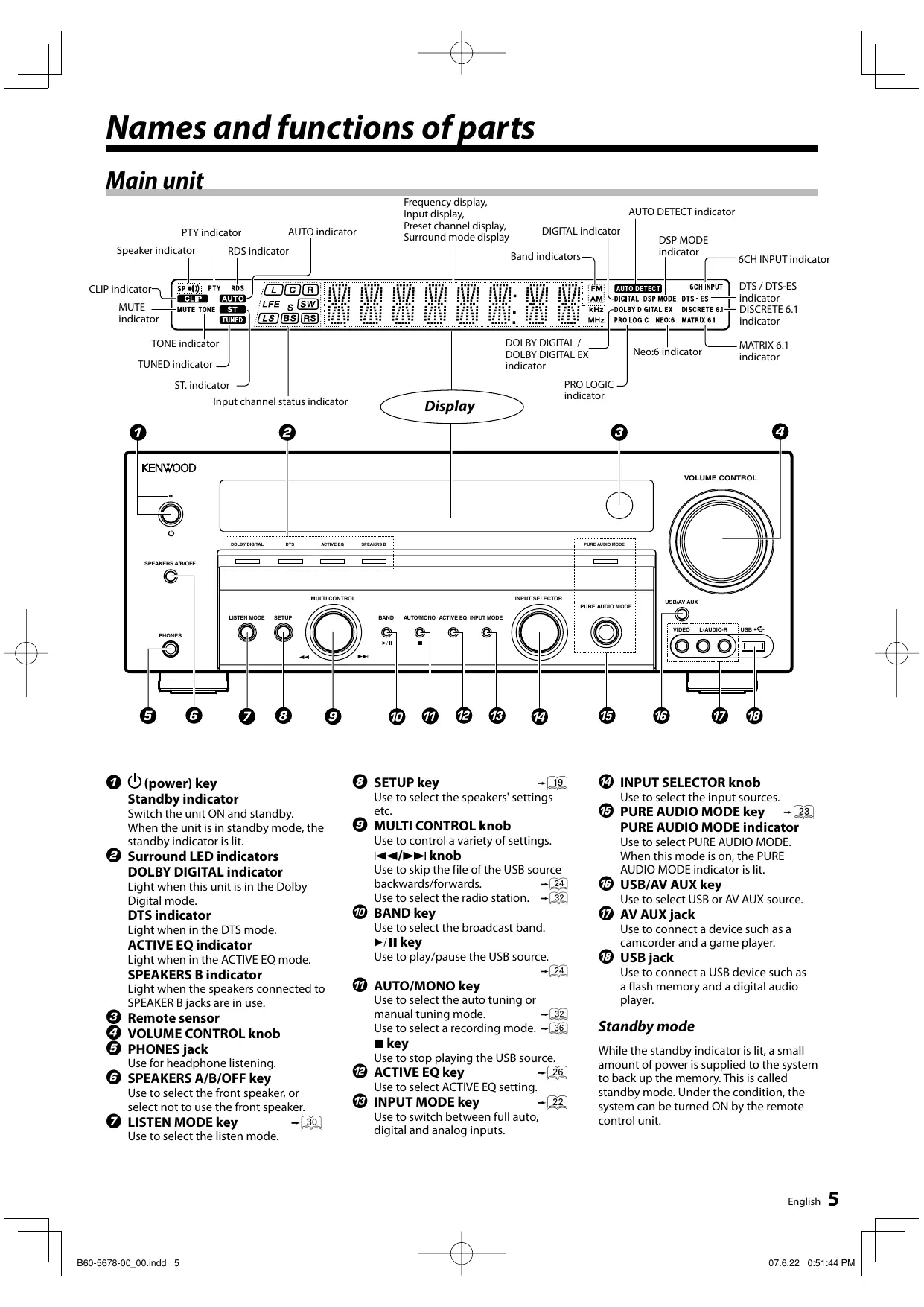
VOLUME CONTROL. ms Ô © () ec ( ) FRE DRE use r® NZ ° @OO) (==. L 6 096 9 © ® © @ © © o © © (power) key © SETUP key -[9) © INPUT SELECTOR knob Standby indicator Use to select the speakers’ settings Use to select the input sources. etc. © PURE AUDIO MODE key Switch the unit ON and standby. When the unit is in standby mode, the standby indicator is lit. © Surround LED indicators DOLBY DIGITAL Light when this unit Digital mode. DTS indicator Light when in the DTS mode. ACTIVE EQ indicator Light when in the ACTIVE EQ mode. SPEAKERS B indicator Light when the speakers connected to SPEAKER B jacks are in use. © Remote sensor © VOLUME CONTROL knob © PHONES jack Use for headphone listening. © SPEAKERS A/B/OFF key Use to select the front speaker, or select not to use the front speaker. © LISTEN MODE key _ Use to select the listen mode. I B60-5678-00 OOindd 5 (5) MULTI CONTROL knob Use to control a variety of settings. Hp» knob Use to skip the file of the USB source backwards/forwards. -| Use to select the radio station. —| © BAND key Use to select the broadcast band. >/Hkey Use to play/pause the USB source.
@ AUTO/MONO key Use to select the auto tuning or manual tuning mode. Use to select a recording mode. — key Use to stop playing the USB source. @ ACTIVE EQ key -(02€ Use to select ACTIVE EQ setting. © INPUT MODE key -C2 Use to switch between full auto, digital and analog inputs.
PURE AUDIO MODE indicator Use to select PURE AUDIO MODE. When this mode is on, the PURE AUDIO MODE indicator is lit. © USB/AV AUX key Use to select USB or AV AUX source. © AV AUX jack Use to connect a device such as a camcorder and a game player. © USB jack Use to connect a USB device such as a flash memory and a digital audio player. Standby mode While the standby indicator is lit, a small amount of power is supplied to the system to back up the memory. This is called standby mode. Under the condition, the system can be turned ON by the remote control unit. Engish 5
Names and functions of parts Remote control unit
——J CL LA H 8 © 6 6 6 666 6
© ANGLE key Use to operate the Kenwood DVD player* © REPEAT key Use to operate the Kenwood DVD player* © AUDIO key Use to operate the Kenwood DVD player* © SUBTITLE key Use to operate the Kenwood DVD player* 6 Engtish I B60-5678-00_OOindd 6
© Numeric keys Use to call up preset stations. Use to operate the Kenwood DVD player* FIRST FILE key -Cà When in the USB source, use to select and play the first file recorded in the USB device. © LISTEN MODE key -G0 Use to select a listen mode. © PURE AUDIO MODE key —[25) Select PURE AUDIO MODE. © ,v,<,1> keys ENTER key TOP MENU key MENU key RETURN key ON SCREEN key Use to operate the Kenwood DVD player* © key Use to operate the Kenwood DVD player* BAND key Use to select the broadcast band. »/Hkey Use to play/pause the USB source. Use to operate the Kenwood DVD player* AUTO/MONO key -5 Use to select the auto tuning or manual tuning mode. mkey Use to stop playing the USB source. Use to operate the Kenwood DVD player* © P.CALL &@/>»1 keys Use to call preset channel. -(64 Use to skip the file of the USB source backwards/forwards. Use to operate the Kenwood DVD player* @ Input source keys Use to select the input source. © AUTO MEMORY key -09 Use for auto memory of RDS and FM radio stations. © MEMORY key -09 Use for manual memory of radio stations. © ORECEIVER key se to turn this unit on and off. O DVD key Use to turn on the Kenwood DVD player on and off. © ACTIVE EQ key 06] Use to select ACTIVE EQ setting. © DIMMER key -C9 Use to adjust the brightness of the display and the indicators. @ BASS BOOST key C6) Use to select the maximum adjustment setting for the low frequency range. © TONE key -28) Use to switch the status of TONE control. © SOUND key -07 Use to adjust the sound quality and ambience effects. © SETUP key C9) Use to select the speakers’ settings. @ EASY SETUP key -59 Use to select speaker setting. @ MULTI CONTROL A/Y keys Select an setup item. © VOLUME A/V keys Use to adjust volume setting. @ MUTE key Use to temporarily mute the sound.
© TUNING <4/>> keys Use to fast backward/fast forward the file of the USB source. Use to select the radio station. Use to operate the Kenwood DVD player* DISPLAY key Use to display the tag information of the USB source.
Use to display RDS information. —| TIME DISPLAY key Use to switch the display of the USB source between play time display and file number display.
@ FOLDER PREV. key Use to select the previous folder of the USB source. FOLDER NEXT key Use to select the next folder of the USB source. © PTYkey -G9) Use for PTY search. Note:
- For how to be able to use the keys to operate the Kenwood DVD player, see <Remote control operations for Kenwood DVD players> -[40] Preparing the remote control Loading batteries EX Remove the cover. El nsert batteries. insert two (R03) batteries following the polarity indications. EX Close the cover. B60-5678-00_O0indd 7 Operation When the Standby indicator is lit, the power turns ON when you press [(1) RECEIVER] on the remote control unit. When the power comes ON, press the key you want to operate. Operating range (Approx.) Standby indicator Remote sensor 30° De à RECEIVER
When pressing more than one remote control key successively, press the keys securely by leaving an interval of 1 second or more between keys. Infrared ray system Notes: The supplied batteries may have shorter lives than ordinary batteries due to use during operation checks. When the remote-controllable distance gets shorter than before, replace both batteries with new ones. Placing the remote sensor in direct sunlight, or in direct light from a high frequency fluorescent lamp may cause a malfunction in such a case, change the location of the system installation to prevent malfunction.
Make connections as shown in the following pages. When connecting the related system components, be sure to refer to the instruction manuals supplied with the components you are connecting. Do not connect the power cord to a wall outlet until all connections are completed. Notes: 8e sure to insert all connection cords securely. Iftheir connections are imperfect, the sound may not be produced or there will be noise interference. 8e sure to remove the power cord from the AC outlet before plugging or unplugging any connection cords. Plugging/ unplugging connection cords without disconnecting the power cord can cause malfunctions and may damage the unit. Do not connect power cords from components whose power consumption is larger than what is indicated on the AC outlet at the rear of this unit
Analog connections Audio connections are made using RCA pin cords. These cables transfer stereo audio signal in an "analog" form, This means the audio signal corresponds to the actual audio of two channels. These cables usually have 2 plugs at each end, red for the right channel and white for the left channel. These cables are usually packed together with the source unit, or are available at your local electronics retailer. Microcomputer malfunction If operation is not possible or an erroneous display appears, even though all connections have been made properly, reset the microcomputer by referring to <Troubleshooting>. [41] À CAUTION The power of this equipment will not be completely cut off from the wall outlet when the power switch is tumed off. Install the equipment so that the wall outlet is easily accessible and, in case of emergency, immediately unplug the power cord from the wall outlet. À CAUTION Be sure to adhere to the following, or proper ventilation will be blocked causing damage or fire hazard. + Leave some space around the unit (from the largest outside dimension including projection) equal to or greater than, shown below. Back panel : 10 cm + This unit is using the cooling fan. Do not place the unit onto a bed, a sofa, a carpet, or similar. Sucked-in dust can cause fire. 8 Engtish B60-5678-00_OOindd 8 etting up the system Speaker placement Front speaker Front speaker | EL à Center speaker Listening ee position Surround speaker Lu a / Subwoofer surround speaker A }
Surround Back speaker (6.1ch) Surround Back speaker (7.1ch) Front speaker: Place the left and right speakers at each side of your TV. Angle the speakers towards the listening area to enhance the stereo effect. Center speaker: Place the center speaker on the center between the front left and right speakers. Tilt the speaker upward or down-ward so that it is directly facing the listening area. Surround speakers: Place the surround speakers as high as possible, either directly to the sides of the listening area or else slightly behind the listening area. Adjust the angles so that these speakers are facing directly towards the listeners. Subwoofer: Usually, place the subwoofer in the front center position in the listening room, near one of the front speakers. (Since the subwoofer has less directivity than other speakers, it can be placed almost in any position that can offer the best low frequency reproduction according to the room layout.) Surround Back speakers: Place the surround back speakers behind the listening position, at the same height as the left and right surround speakers. For 6.1-channel speaker system, place one surround back speaker. For 7.1-channel speaker system, place left and right surround back speakers. Note: + Although the ideal surround system consists of all the speakers isted above, if you dont have à center speaker or a subwoofer, you can divide those signals between the available speakers in the speaker settings steps to obtain the best possible surround reproduction from the speakers you have available.
Digital connections The DIGITAL IN jacks can accept DTS, Dolby Digital, or PCM signals. Connect components capable of outputting DTS, Dolby Digital, or standard PCM (CD) format digital signals. If you have connected any digital components to this unit, be sure to read the <Selecting the input mode> -[22] carefully. @l@6 €| (@|@) @|66 €] er @|6|6 Æ'o | / 6 6[6 © ele ele e| |0Û 6 6l6 © ele 6e
GOAXIAL DVD/8CH COAXIAL DIGITAL OUT (AUDIO) ( 2—— 0 20: -) CD or DVD player OPTICAL COMDVD DIGITAL IN Australia Other countries OPTICAL VIDEOZ EE To AC wall outlet À CAUTION Do not connect power cords from components whose power consumption is larger than what is indicated on the AC Optical fiber cable Component with DTS, Dolby Digital, or PCM
OPTICAL DIGITAL OUT*
EE, OPTICAL DIGITAL OUT (AUDIO) ô outlet at the rear of this unit. Note:
- Connect the video signal and analog audio signals to the VIDEO 2 jacks. (<Connecting video components> —[12]) B60-5678-00_OOindd 9 English 9
Setting up the system Connecting a DVD player (6-channel input) If you have connected a DVD player to this unit with digital connection, be sure to read the <Selecting the input mode> [22] carefully. KRF-V6200D
GoaxlAL | OPTICAL Ge) DVDiécH | CD/DVD DIGITAL IN FRONT | surRounD| suBwooFER CENTER
OUTLAR | OUT LR OUT OUT
® OC Jo’: Monmapiena OUT (AUDIO) DD player VIDEO OUT (Yellow RCA pin cord) Note: {the DVD player has COMPONENT VIDEO OUT, COMPONENT VIDEO connection is possible. (<Connecting video components (COMPONENT VIDEO)> -C 10 Engish I B60-5678-00_OOindd 10
07.622 0:51:50 PM Il
Connecting audio components To AC wall outlet Cassette deck or MD player ET 0) CD or DVD player —— Other component OUT English 11
Setting up the system Connecting video components
About the S-VIDEO jacks If you use the S-VIDEO jacks to connect your video components, be sure to connect your monitor and
AUDIO viol OUT OUT CETTE: DVD player Video component with VIDEO OUT recording function
VIDEO Monitor TV Note: + Avideo component with digital audio outputs should be connected to the VIDEO 2 jacks 12 Engish
DVD player AUDIO OUT Video component with recording function VIDEO OUT Monitor TV
AUDIO OUT Video component RE ——_—] VIDEO OUT Notes:
- Ifthe DVD player has 6 channel output, connecting to DVD/6CI N jacks is possible. (<Connecting a DVD player (6-channel input)> if some of the video equipment are connected to the COMPONENT jacks and the rest are connected to the normal (composite) VIDEO; jack, make sure to connect the TV to the MONITOR OUT jacks of both COMPONENT VIDEO and VIDEO Depending on the type of TV, it may be necessary to switch the input of the TV according to the type of video input (COMPONENT input or COMPOSITE input). Refer to the instruction manual of your TV for more information. I B60-5678-00_OOindd 13 English 13
Setting up the system Connecting the speakers (KRF-V7200D) Powered subwoofer To AC wall outlet For 6.1-channel speaker configuration, connect the surround back speaker to this terminal. Select "BS MONO" in the speaker setup. -[20) Right Left Center speaker Front speakers B Right Left Right Left Right Left Front speakers À Surround speakers Surround Back speakers Note: + Speakerimpedance After confirming the speaker impedance indications printed on the rear panel of the receiver, connect speakers with matching impedance ratings. Using speakers with a rated impedance other than that indicated on the rear panel of the receiver could result in malfunctions or damage to the speakers or the receive. 07622 0:51:55PM Il 14 Engish I B60-5678-00_O0indd 14
I B60-5678-00_OOindd 15 Connecting the speakers (KRF-V6200D) Surround Back speakers Late Right For 6.1-channel speaker configuration, connect the surround back speaker to this terminal (with power amplifier connected in between). Select "BS MONO" in the speaker setup Power Amplifier FRONT SPEAKERS (6-160) SURROUND SPEAKERS (6-16)
® © © Q Right Left Center speaker Front speakers B CR (© © Right Left Right Left Front speakers À Surround speakers Note: + Speakerimpedance After confirming the speaker impedance indications printed on the rear panel of the receiver, connect speakers with matching impedance ratings. Using speakers with a rated impedance other than that indicated on the rear panel of the receiver could result in malfunctions or damage to the speakers or the receive. English 15
Setting up the system Connecting the terminals Connecting to the AV AUX jacks El Strip coating. and USB jack PIS: VIDEO L-AUDIO-R eo Notes: Never short circuit the + and - speaker cord. the left and right speakers are connected inversely or the speaker cords are connected with reversed polarity, the sound will be unnatural with ambiguous acoustic imaging. Be sure to VIDEO OUT AUDIO OUT connect the speakers correctiy Camcorder, game player, USB devi andetc. (commercially available) {commercially available) Notes: Usable USB devices The following restriction are applicable to the type ofthe USB device = The USB device should be USB mass storage class compatible. = The maximum current drain should be no more than 500mA, For more information on usable USB devices, see <Playable USB device and files> -C 16 Engish B60-5678-00 OOindd 16 DA 07.622 0:51:58 PM
Connecting the antennas
90) connected. Connect the antennas correctly as instructed below. The broadcast reception cannot be made unless the antennas are EE Sebpie | Ho | 6\s © AM loop antenna CR le o Place the supplied loop antenna as far as possible from the receiver, TV set, speaker cords and power cord. Adjust the direction for best reception. El attach to the stand. El Push the lever. DC:
(commercially JT available) EX Release the lever.
EPlace the antenna and adjust the direction. FM indoor antenna The supplied indoor antenna is for temporary use only. For stable signal reception we recommend using an outdoor antenna. Disconnect the indoor antenna when you connect one outdoors. EX insert the antenna cord.
Elrixthe antenna on the wall. FM outdoor antenna Lead the 750 coaxial cable connected to the FM outdoor antenna into the room and connect it to the FM 750 terminal.
Speaker settings Speaker setup (Easy Setup) The speaker settings can be completed by simply selecting the room type and listening position. The audio will be corrected automatically according to the characteristics of the speaker system in use. If more detailed speaker settings are required, use the procedure in <Speaker setting flow> [191 EASY SETUP es - MULTI CONTROL 4/v EX Press [EASY SETUP] to enter the easy setup mode. EX Use IMULTI CONTROL A/v] to select the speaker configuration. (KRF-V7200D only) Display Selection 1 The speaker configuration consists The speaker configuration consists of5 For KRF-V6200D, skip this step. ElPress [EASY SETUP]. EX Use IMULTI CONTROL A/v] to select your room type. 5m (165-3/8) Am (1311-7/8) :| & ä L8/L-8,61) 9 12m? (SMALL } 24m? (MEDIUM ) 35m? (LARGE }) Press [EASY SETUP]. 18 Engish I B60-5678-00_OOindd 18
EX Use IMULTI CONTROL A/v] to select your listening var Press [EASY SETUP]. + The speakers are set up as shown below. Subwoofer : ON Front speaker: Average size Center speaker: Average size Surround speaker: Average size Surround back speaker {KRF-V7200D: When "7_1" is selected in step EX)
Subwoofer re-mix* : ON The function for adding the bass of other channels to the subwoofer channel according to the speaker setup. Note: Easy setup with may not be appropriate with certain speaker systems or listening environment. In this case, go through <Speaker setup ('SP SETUP")> [29]
Speaker setting flow The detailed settings below allow you to enjoy full performance ofthe receiver according to the environment of your listening room. Speaker settings consist of 4 elements. Speaker Setup ("SP SETUP") —[: Select whether each speaker channel is used or, if used, its size. The Easy Setup function also allows you to make speaker settings easier. See <Speaker setup (Easy Setup)> -[18 D « Test Tone ("TEST TONE") -[20] Select the output level from each speaker. D 4 Distance ("DISTANCE") [21] Select the distance between each speaker and the listening position. > À Low Frequency Effects Level ("LFE LVL") -[21] Select the level of bass audio enhancement. Low Frequency Effect channel delivers separate non-directional bass signals to the subwoofer for more dynamic deep bass sound effects. D À Speaker settings completed! Getting into the setup mode The setup procedure is identical for all of the setting elements. Once you remember the following procedure, you can easily set up other setting elements. .lf@" Oo
OOO s——SETUP —l-mun CONTROL AIY Sosa ocoa EX Press [SETUP] to enter the setup mode. EX Use [MULTI CONTROL A /v] to select the element to setup. Display Selection SP SETUF Speaker set ESTTONE" Testtone Distance frequency effects level Bitte setup mode El Press ISETUP] to get into the setup mode of the selected element. To exit the setup mode Select "EXIT" in the step EX and press [SETUPI]. English 19
Speaker setti gs Speaker setup ("SP SETUP") This sets up the speakers according to the speaker system in use. Speaker setup is required every time the speaker system is changed. EX See <Getting into the setup mode> (-[i£]) and select "SP SETUP". EX Use [MULTI CONTROL 4 /v] to select the subwoofer setting. Speaker Display Selection 'SUBW ON" With Subwoc P'SUBW OFF" Without Subwoofer
Subwoofer war EPress [SETUP]. EX Repeat steps EX - EX for the rest of the speaker setting. Speaker Display Selection EAN LARG" Large sie front speaker Front speaker PERNTNML Average size front speaker ONTR NL" Average size center speaker Center speaker Large ie center speaker No center speakers connected. SURR NAIL Average size surround speaker Suround speaker "SURRLAG" Large size surround speaker SURR OFF" No surround speaker is connected. Large ie surround back speaker Average size suroun back speaker No suround back speaker is connected Surround Back speaker SLR Left and Right Surround Back speakers are connected. »S MONg'= Only one Surround Back speaker is connected. Subwoofer re- Subwoofer re-mix is on. Subwoofer re-mix is off. This selection is available when either "BS LRG" or "BS NML'is selected. 2 The function for adding the bass of other channels to the subwoofer channel according to the speaker setup. EX Go to the next setting, "TEST TONE". (you wish to exit the setup mode, see <To exit the setup mode> Notes: + When "SUBW OFF" is selected, the front speakers are automatically set to "FRNT LRG" For *FRNT LRG' selection, no sound will be heard from subwoofer even it is set to ON. However, if you select "RMX ON" you will be able to hear sound from the subwoofer. When in STEREO mode, the sound goes directiy to front speakers. IF*FRNT NML'is selected, "CNTR LRG" cannot be selected (F*CNTR NML or "CNTR OFF" is selected, "SURR LRG" cannot be selected 20 Engiish B60-5678-00_OOindd 20 IF'SURR OFF is selected, no surround back speaker can be selected. "85 LARG" cannot be selected unless "SURR LRG' is selected. "BS MONO" is selected, surround back signal can only be output at the SURROUND BACK L terminal Adjusting the speaker level (TEST TONE") From your usual listening position, adjust the volume output of each speaker. The output level from each speaker should be the same. EX See <Getting into the setup mode> (-[19)) and select "TEST TONE". A Use [MULTI CONTROL A /v] to select either "AUTO" or "MANUAL". Display Selection The test tone is heard from the speakers one after another with ATOS 2 seconds each. MANUAL" The test tone is heard from the speaker you have d. ElPress ISETUP]. Ed Adjust the output level. If you select "AUTO": When you hear the test tone from the speaker which you wish to adjust, use [MULTI CONTROL A/vw] and adjust the volume of the test tone. When you finish adjusting, press [SETUP]. If you select "MANUAL": Use [MULTI CONTROL A/v] to adjust the volume of the test tone and press [SETUP]. You will hear the test tone from the next speaker. Far EX Go to the next setting, "DISTANCE". (you wish to exit the setup mode, see <To exit the setup mode>
Distance setting ("DISTANCE") This sets the distance from each speaker to the listening position. EX Mesure the distance from the listening position to each speaker and jot down in the table below. Input channel Distance from the listening suc status indicator position Front speaker let) feet Center speaker Front speaker (right) Surround speaker (right) Surround Back speaker (right) Surround Back speaker let) "BS feet (meters)
round Back speaker" ES Surround speaker (ef) L Subwoofer ET feet + This selection is available when "BS MONO" is selected in the speaker setup. EA See <Getting into the setup mode> (— select "DISTANCE". EX Use [MULTI CONTROL 4/v] to select the distance to the front speaker. Adjustment will start from front left speaker. Input channel status indicator ET] Ed Press ISETUP]. EX Repeat steps EX - EX to input the distance for the rest of the speaker. EX Go to the next setting, "LFE LVL". fyou wish to exit the setup mode, see <To exit the setup mode> I B60-5678-00 OOindd 21 Low frequency effects level C'LFE LVL") Low frequency effect signal is used exclusively for giving the field effect of bass tone in the Dolby Digital and DTS signal. EX See <Getting into the setup mode> (-[19)) and select "LFE LVL". EX Use [MULTI CONTROL A/v] to adjust the low frequency effect level. The level is adjusted from OdB to -10dB in 1dB step decrements C7] The setup is complete when the "EXIT" indication appears. EX Press ISETUP] to exit the setup mode. Engish 21
Normal Playback Preparing for playback Some preparatory steps are needed before starting playback. (Ge INPUT SELECTOR GsS=
GRECEIVER LISTEN MODE — Input source keys Turning on the power EX Turn on the power to the related components. ElPress 10 RECEIVER] to turn on the receiver unit. Setting the speaker status (main unit only) Press [SPEAKERS A/B/OFF] to switch the speaker on or off. The speaker indicator lights up when set to on
"SPEAKERS B' indicator lights up when the speakers connected to the SPEAKER B terminals are selected, Notes: + Set Speakers to OFF for stereo playback. When Speakers is set to ON again, the listen mode remains in stereo ifthe input signal is digital + When the input mode is "6CH INPT! SPEAKERS B cannot be selected 22 Engiish I B60-5678-00_OOindd 22 Selecting the input mode (main unit only) If you have selected a component connected to the DIGITAL IN jacks (CD/DVD, VIDEOZ2 and DVD/6CH INPUT), make sure that the input mode setting is correct for the type of audio signal to be used. EX Use [INPUT SELECTOR] to select "CD/DVD", “VIDEO?2", or "DVD/6CH". El Press [INPUT MODE]. Each press switches the setting as follows: Display Setting Input signal FAUTO"* Full Auto Digital input or Analog input D-MANUAL' Digital Manuel Digital input 3 échinput DVD/ECH input ANALOG"®* Anloginput Analoginput “1 Factory setting. +2 "6CH INPT" setting can be switched only when the input selector s set to "DVD/6CH
- This cannot be selected when in DTS play mode Full Auto ("F-AUTO"): The unit detects the digital or analog input signal automatically. The unit selects the input mode and listen mode automatically during playback to match the type of input signal (Dolby Digital, DTS or PCM) and the speaker setting. Normally use Full Auto. In this mode, "AUTO DETECT" indicator lights up. "DIGITAL" indicator also lights up when digital input signal comes in. AUTO DETECT" and "DIGITAL" jpdicators Far DES
Digital Manual ("D-MANUAL'"}: Some discs produce sound skipping even when "F- AUTO" is set. Select "D-MANUAL' with such a disc. Digital Manual accelerates the input signal processing by fixing the listen mode and therefore minimizes sound skipping during disc playback. If audio reproduction stops in the middle due to change in the input signal, press [LISTEN MODE]. 6ch input ("6CH INPT"): Select this setting to play the DVD player connected to DVD/6CH IN jacks. Analog input ("ANALOG"}): Select this setting to play analog signals from a cassette deck, VCR, or record player. Note: [INPUT MODE] is pressed too quickly, sound may not be produced. Press [INPUT MODE] again.
Listening to a source component VOLUME CONTROL VOLUME 4/v Sosa Basso) aSSS Sooo) Input source keys EX Select the source you want to listen to. When using the remote control unit: Use the Input source keys to select a source. The following input source keys are prepared on the remote control unit: [TUNER] (FM/AM broadcast reception) [CD/DVD] IMD/TAPE] [VIDEO] [VIDEO2] IDVD/6CH] [AUX] [AV AUX] [USB] When using the main ui Use [INPUT SELECTOR] to select a source. The input sources change as shown below with [INPUT SELECTOR]: }Tuner (FM/AM broadcast reception) CD/DVD" MD/TAPE" DVD/6CH" AUX" Use [USB/AV AUX] to select USB or AV AUX source. "USB" "AV AUX" El Start playback from the selected source. EL Use [VOLUME A/V] to adjust the volume. B60-5678-00_OOindd 23 Listening to music with
The PURE AUDIO MODE allows you to enjoy music sources in high-quality stereo.
EX Select the music source you want to listen to. El Start playback from the selected source. El Press [PURE AUDIO MODE]. + While in PURE AUDIO MODE, the listen mode is set to stereo. PURE AUDIO MODE indicator lights up, the display will be turned off, and no video signal is output to the TV monitor. — No video signal to the TV monitor. | PURE AUDIO MODE indicator lights up. The display is tumed off. To cancel Press [PURE AUDIO MODE] again. PURE AUDIO MODE is also canceled when listen mode is changed. See <Surround play>. -[36 Notes: + When the input mode is "6CH INPT' the listen mode does not change. (<Selecting the input mode> —[22]) + When the PURE AUDIO MODE is canceled, the listen mode remains in stereo if the input signal is digital Engish 23
Operation of USB source Audio files such as MP3 files, WMA files and AAC files can be enjoyed through a USB device. For the information on usable USB devices and audio files, see <Playable USB device and files> -[2 FIRST FILE "| of dep —CDCD;- <>» oooa
DISPLAY— ERP —TIME DISPLAY
STE SScEr- FOLDER PREV. FOLDER NEXT Preparations + Connect a USB device to the USB jack on the front panel. + Select USB source. -[3] Play Press [»/ + The display shows the file number and then changes to the play time. File number display Fast forward and backward (remote control only) Press [>>] for fast forward. Press [-«-<«] for fast backward. Keep pressing the key until you reach the desired point. Play stats when the key is released + The display shows the play time File skip Press [-@-<«] or [»-»1]. + The display shows the file number and then changes to the play time. WU is pressed while playing, the play start from the beginning ofthe currently playing file Jumping to the first file (remote control only) Press [FIRST FILE]. + The display shows the file number and then changes to the play time. Folder skip (remote control only) Press [FOLDER PREV.] to select the previous folder. Press [FOLDER NEXT] to select the next folder. + The play will start automatically Displaying the tag information (remote control only) When playing a file containing information such as track titles, you can see the information. Press [DISPLAY]. The information are changed as follows: ar ET] Play time display [7] © ® the play is stopped or the other source is selected, the unit remembers the last playing file. The next time the play wil start from the flle at which the play is stopped Pause Press [»/ Pressing e/HN again cancels pausing + The display shows the play time Stop Press [m]. + The display shows the play time 24 Engiish I B60-5678-00_OOindd 24 Display Information ILE" Te title ofthe playing le ARTIST The name ofthe artist ft fle ALBUM The name afthe album in which the fl is included + The selected information is scrolled from right to left. (there is no tag information, "NO TITLE" will be displayed Play time display (remote control only) Press [TIME DISPLAY]. + The elapsed time of the playing fil is displayed Pressing [TIME DISPLAY] again shows the file number. Note: + When playback is impossible, a message appears on the display. See <USB message list> (-[42)) for detailed information for each message.
Playable USB device and files USB device + Playable USB device Flash memories and digital audio players which work as mass- storage-class devices. The maximum current drain should be no more than 500mA. + Playable USB device file system FAT16, FAT32 - Applicable memory FAT32 : 256MB or larger FAT16 : 128MB or larger + Subclass scsi - Limitation of structure for the file and the folder Maximum number of directory levels: 8 Maximum number of folders: 700 Maximum number of files: 65535 Notes: Take backups of the audio files used with this unit. The flles can be erased depending on the operating conditions ofthe USB device We shall have no compensation for any damage arising out of erasure of the stored data. Using an unsupported USB device can result in abnormal playback or display of the audio file. Even if you use the USB device conforming to the above specs, audio files cannot be played normally depending on the type or condition of the USB device B60-5678-00_OOindd 25
lotes: WMA files which cannot be played with this unit — WMA 9 series Professional — WMA 9 series Voice — WMA 9 series Lossless — WMA file which contains video The files with copy protection cannot be played! The unit may not be compatible with upgrade of compression format standard and additional specifications This unit can display the following versions of ID3 tag; version 10/11/22/23 Engish 25
One-touch low frequency emphasis (Bass Boost) (remote control only) You can adjust the sound quality when this unit is in the PCM stereo and analog stereo modes. Press [BASS BOOST]. Press the key once to select the maximum (+10) low frequency emphasis setting. + TONE will automatically be turned ON. + This key does not function when this unit is in the sound quality or ambience effects adjustment mode. + When the ACTIVE EQ mode is set to ON, set it to OFF and then s s s è control the Bass Boost setting, Es MULTI CONTROL To cancel AY Press [BASS BOOST] again. CODE MUTE Muting the sound (remote control only) So) Press [MUTE] to mute the sound of the speakers. e = = = "MUTE" indicator blinks. A œ Adjusting the Tone (remote control only) LAS You can adjust the sound quality when this unit is in the PCM stereo and analog stereo mode. El Press ITONE] to select the Tone mode. A Use [MULTI CONTROL À/v] to select "TONE ON" or "TONE OFF". Fur œ E When in "TONE ON" selection, press [TONE] for the following displays. To cancel Press [MUTE] again so that the "MUTE" indicator goes off. + MUTE can also be deactivated by adjusting volume ACTIVE EQ mode You can enjoy a more impressive sound effect when ACTIVE EQ is turned ON during Dolby Digital and DTS playback and, when in PCM and analog stereo mode. Press [ACTIVE EQ] for the following selections. Display Setting Display Si Re ACTIVE EQ MUSIC" Efective when istening to music. BASS" Adjusts low frequency range. =10= +10 (in 2 step) ACTIVE EQ CINEMA" Effective when watching à movie. TRES" Adjusts high frequency range 10 +10 (in 2 sep) EX Use IMULTI CONTROL A/v] to adjust the sound quality. Fur + When the ACTIVE EQ mode is set to ON, set it to OFF and then control the TONE setting, Press [TONE].
Effective when lang à game. Active EQ function is off. + ACTIVE EQ function will not be available when REC MODE, AUTO TUNING or PRESET MEMORY is ON and during 96kHz LPCM playback ACTIVE EQ indicator lights up. 26 Engiish I B60-5678-00_OOindd 26
Ambience effects The below speaker placements are for 7.1 channel Surround modes surround sound system which are; This unit is equipped with listen modes that allow you to enjoy an + Dolby Pro Logic IIx enhanced sonic ambience with a variety of video sources. + Neo:6 In order to obtain the optimum effect from the surround modes, make sure to input the proper speaker settings beforehand. See <Speaker settings> -[16]. TV / SCREEN The below speaker placements are for 5.1 channel c*) (SWCc ) surround sound system which are; Dolby î Dolby Pro Logic Il DTS DSP mode DVD 6-channel De >= © HE (LB) (RE) L: Front Left speaker LS) A Rs SW: Subwoofer C: Center speaker R: Front Right speaker LS: Surround Left speaker RS: Surround Right speaker BS: Surround Back speaker LB: Surround Back Left speaker RB: Surround Back Right speaker The below speaker placements are for 6.1 channel surround sound system which are; © EE
(BS) Manufacture under license from Dolby Laboratories. "Dolby" "Pro Logic" and the double-D symbol are trademarks of Dolby Laboratories. "DTS","DTS-ES" and "Neo:6" are =) dts registered trademarks of DTS, Inc. Digital Surround ES’ | Neo” English 27
Ambience effects Dolby Digital Dolby Digital is a highly sophisticated and versatile audio encoding/decoding technology. Dolby Digital technology can transmit mono, stereo (two-channel), or up to 5.1-channel surround sound (discrete* multichannel audio). In 5.1-channel surround sound, the three front channels (Left/Center/Right) deliver crisp, clean dialogue and accurate placement of on-screen sounds, while twin surround channels (Left Surround/Right Surround) wrap around the audience and immerse them in the action. The LFE (Low-Frequency Effects) channel delivers real impact for explosions and other effects that can, literally, be felt as well as heard. The superior coding efficiency of Dolby Digital-and its ability to deliver high-quality discrete multichannel audio without compromising video quality has made it the designated audio standard for DVD worldwide. *The sound information contained in each of the six available channels is distinct and independent. These six channels are described as a "5.1-channel" system, because there are five full-bandwidth channels with 3 Hz to 20 kHz frequency range for Front Left and Right, Center, and Surround, plus one "Low Frequency Effects" (LFE) subwoofer channel devoted to frequencies from 3 to 120 Hz. Dolby Digital EX Dolby Digital EX takes the Dolby Digital 5.1-channel setup one step further with an additional center surround channel (reproduced through one or two speakers) for extra dimensional detail and an enveloping surround sound effect. Feature films originally released in Dolby Digital Surround EX (the cinema version) carry the encoded extra surround channel in their subsequent DVD releases, as well as onto 5.1-channel digital satellite and TV broadcasts. With this receiver, you can hear Surround EX soundtracks as they were meant to be heard, with the increased realism created by the extra surround channel. Dolby Pro Logic Il Dolby* Pro Logic® Il technology processes any high quality stereo {two-channel) movie and music audio into five playback channels offull-bandwidth surround sound. À matrix surround decoding technology, Dolby Pro Logic Il detects the directional cues that occur naturally in stereo content and uses these elements to create a five-channel surround sound playback experience. Dolby Pro Logic Il is fully compatible with all Dolby Pro Logic technologies. It provides optimal audio for playback in a 5.1- channel home theater system for the thousands of videocassettes and TV programs encoded in four-channel Dolby Surround (the encoding counterpart to Dolby Pro Logic's decoding technology). (Dolby Pro Logic II surround Movie mode) Dolby Pro Logic Il also enables video game consoles to encode five-channel surround sound information into a stereo signal with virtually no impact on the console's CPU, which means all this extra audio won't slow your game down. (Dolby Pro Logic 11 surround Game mode) Dolby Pro Logic Il can bring new life to your CD collection. Play your music through your home theater system, and you'll hear seamless, natural sound with new depth and detail. It's almost like hearing a newly remastered CD. (Dolby Pro Logic Il surround Music mode) 28 Engiish B60-5678-00_OOindd 28 Dolby Pro Logic Ix Dolby Pro Logic IIx transforms any stereo or 5.1-channel signal into six- or seven-channel, full range surround sound, creating a seamless, natural surround soundfield that immerses you in the entertainment experience. Three listening modes, Movie, Music or Game allow you to tailor the audio to meet the different needs of the programming. In Game mode, for instance, special effects signals are routed to the surround channels for fuller, dramatic impact. Music mode features three additional use controls: + Dolby Center Width adjusts the balance of the main vocals in the center and front channels. + Dolby Panorama creates a seamless, wraparound surround effect. + Dolby Dimension lets you set a deeper or shallower surround soundfield. DTS DTS Digital Surround is the standard for providing 5.1 channels of discrete digital audio in consumer electronics products and software content. DTS can contain a larger volume of data than Dolby Digital, and can reproduce high quality surround sound. They are the same as the Dolby Digital 5.1 channels, but it is a format that lowered the audio compression rate when recording digitally. Because of that, rich sound with high S/N can be reproduced. Moreover, an exact, magnificent surround sound with wide dynamic range and excelling in separation is a feature of DTS. DTS has a "1" or LFE channel. The indication "LFE" appears in the display when a signal is being input for this channel. DTS-ES In the cinema, the center surround channel is not discrete, but is matrixed into the left surround (LS) and right surround {RS) channels. Embedded in the soundtrack print master, this matrixed channel works with all cinema digital sound formats. DTS calls this process Extended Surround, or "ES". Neo:6 Neo:6 provides up to six full-band channels of matrix decoding from stereo matrix material. Users with 6.1 and 5.1 systems will derive six and five separate channels, respectively, corresponding to the standard home theater speaker layouts. (The "1" subwoofer channel is generated by bass management in the receiver.) Neo:6 provides optimum decoding of Extended Surround matrix soundtracks, and can also generate a center surround channel from 5.1 material. Neo:6 technology allows various sound elements within a channel of channels to be steered separately, and in a way which follows the original presentation naturally. Neo:6 offers a music mode that expands stereo non-matrix recordings into the five- or six-channel layout without diminishing the subtlety and integrity of the original stereo recording.
DSP mode The DSP mode lets you add the atmosphere of a live concert or hall to almost any type of program source. These modes are particularly effective when used with stereo program sources, like CD, television, and FM radio. You might enjoy trying the ARENA, JAZZ CLUB, THEATER, STADIUM or DISCO mode the next time you watch a concert or sporting event! What's DSP? DSP stands for Digital Signal Processor. The way a sound is heard in an actual environment depends on a variety of different factors. One of the most important is reverberation (the act of decaying elements of sound echoing in various places). The DSP modes produce the feeling of presence by using the DSP to create reverberation, without spoiling the sound quality of the original signal. DVD 6-channel mode Using a DVD player or the like equipped with six (5.1) output channels and this unit, you can enjoy multi-channel encoded DVD source material in all its splendor. Since the source signals are digital and each channel is input independentiy, the resulting sound quality, sense of spaciousness, and dynamic range are superb. The indication "6CH INPUT" appears in the display during DVD 6-channel mode selection. Note: LFE = Low Frequency Effects This channel delivers separate non-directional bass signals to the subwoofer for more dynamic deep bass sound effects. B60-5678-00_OOindd 29 About indicators for surround mode spa) pv pos MUTE TONE
FOGTAL DSP AGDE Drs-Es
Input channel status indicators Surround mode indicators Input channel status indicator It shows the channels contained in the input signal. Note that the input channel indicator does not show the channel of the listen mode. The "LFE" indicator lights when the low frequency effects level is adjusted. See <Low frequency effects level ('LFE LVL')> ( The "S" indicator lights when the surround component consists of a single channel. Surround mode indicator The indicator for the selected listen mode lights up. "DIGITAL" also lights when the input signal is digital. English 29
Ambience effects Surround play PLIMUSIC* Pro Logic surround Music mode “DOUBY DIGITAL ‘ and"PRO LOGIC Select the listen modi ding to th being played back. “DoLBY DG ASSIS PSE MIOGS BECONENI 10 RRE ROUES ENS P'aYEE Dee PLI GAME"* Pro Loge surround Game mode Dos Di and"PRO LOGIC é RO IOGiC* "DOLBY DIGI CRI PRO LOGIC Pro Logic mode ns ROUE ° STEREO" Stereo mode “DOLBY DIGITAL" e |[?° *_ Available when the input signal has only 2 channels. LISTEN MODE When "Dolby Digital EX" is selected: "DOLBY DIGITAL EX" will scroll from right to left. = Fo Er —— ES . d "DOLBY DIGITAL EX" indicator is lit. When the DTS signal is input: LISTEN MODE — er") 9 Pi Display Listen mode Indicator [_ VOLUME av DIS-+NEDG chaux DIS + Nens suround Cinema mode DIS" and'Nen: ES MARNE DIS ES MATRIX 1 chamelsuround mode os SDS on 4 DSCETE 6 1 chanel suround mode Preparations rs DIS 5.1 channel suround mode +_ Turn on the related components. STEREO" Stereo mode Ds + Complete <Speaker settings>. rene + Select the source you wish to play back with When "DTS" is selected: surround sound. Select the input mode (analog or 1) for the source you wish to playback. (Noise may be produced when a DTS source is played by selecting «0 - the analog input.) [22] DTS" will scroll from right to left. IE] T Far
2) "DTS" indicator is lit.
Notes: + Depending on the type of the signal or speaker setting, some isten modes cannot be selected. When playback is started, the sound may be cut or interrupted before the input source is confirmed as Dolby Digital. To enjoy Dolby Digital surround (as well as all the other listen modes) from à single component, be sure to use a Dolby Digita compatible source component. Dolby Digital or DTS signal having more channels than the maximum number of playback channels available using this units current settings is input, downmixing is performed to match the number of available channels Some Dolby Digital Surround EX compliant discs do not contain identification signals. For this reason, the receiver may not detect these discs as Dolby Digital EX when the input mode is set to *F- AUTO" In this case, set the listen mode to "DOLBY DIGITAL EX" 96kHz LPCM playback This unit is compatible with the 96kHz LPCM playback. To play a 96kHz DVD, set the listen mode to "STEREO". n *F-AUTO" input mode, the listen mode will automatically be STEREO. When in "D-MANUAL' input mode (listen mode is not STEREO), FS 96kHz' will appear in the display and no sound can be heard from the speakers Press [LISTEN MODE] (the listen mode changes to the "STE! mode) to output sound from the speakers. £O" B60-5678-00 OOindd 31 DVD 6-channel playback Using a DVD player or the like equipped with six (5.1) output channels and this unit, you can enjoy surround sound playback. Connecting a DVD player which can decode the surround signal itself is also acceptable. INPUT SELECTOR — VOLUME 4A/v (œrmimim)
occa) sowo Soc DVD/6CH Preparations + Connect your DVD player to the DVD/6CH INPUT jacks of this unit. + Turn on all other components that will be used. + Complete <Speaker settings>. EX Select "DVD/6CH" as the input source. El Press LINPUT MODE] to select "6CH INPT". El Start playback of a DVD disc. El Adjust the volume. Notes: k is not possible to adjust the speaker level or sound effect {ISETUPI, [SOUND), [LISTEN MODE), [ACTIVE EQ] and [TONE] will not be functional) of the channels separately when this unit is in the 6CH INPUT mode. Adjust the speaker level with the controls ofthe DVD player. Refer to the Instruction manual of the DVD players for the detailed operating instructions For the powered subwoofer, you can adjust the volume of the subwoofer using the subwoofer s own volume control Engish 31
istening to radio broadcasts This unit can store up to 40 stations in the memory and recall them by one-touch operation. Radio stations can be classified into RDS (Radio Data System) stations and other stations. To listen to or store RDS stations in the preset memory see <Using RDS (Radio Data System)>. Tuning (non-RDS) radio stations
EX Use [TUNER] to select the tuner. A Use [BAND] to select the desired broadcast band. Each press switches the band as follows:
EX Use IAUTO/MONOI] to select the desired tuning method. Each press switches the tuning method as follows: Selection Operation Indicator Auto tuning The next station is tuned automatically. “AUTO" lit Manual tuning Select a station manually. AUTO" not lit [" éè © ©. Normally, set to "AUTO" (auto tuning). the radio waves are weak and there is a lot ofinterference, switch to manual tuning. (With manual tuning, stereo broadcasts will be received in monaural) EX Use [MULTI CONTROL A /] or [TUNING -æ-«/»->-] to select the station. "ST: lights when a broadcast is being received in stereo. 32 Engiish I B60-5678-00_OOindd 32 Using RDS (Radio Data System) RDS is a system that transmits useful information (in the form of digital data) for FM broadcasts along with the broadcast signal. Tuners and receivers designed for RDS reception can extract the information from the broadcast signal for use with various functions, such as automatic display of the station name. Before using a function utilizing the RDS, be sure to perform the RDS Auto Memory operation by referring to the description in <RDS Auto Memory>.(--[55]} RDS functions: RDS AUTO MEMORY function Automatically selects and stores up to 40 RDS stations in the preset memory. If fewer than 40 RDS stations have been stored in the preset memory, regular FM stations will be stored in the remaining places. PS (Program Service) Name Display Automatically displays the station name transmitted by the RDS station. PTY (Program TYpe) identification Search Automatically tunes to a station that is currently broadcasting the specified program type (genre). RT (Radio Text) function Displays the radio text data transmitted by some RDS stations when you press [DISPLAY]. There is "NO RT' or "RT —" display if no text data is transmitted. The "RDS" indicator lights up when an RDS broadcast (signal) is received. TS ©
Note: Some functions and function names may differ for certain countries and areas.
RDS Auto Memory This function automatically stores up to 40 RDS stations in the preset memory. In order to use the PTY function, the RDS stations must be stored in the preset memory using the RDS AUTO MEMORY function. BAND TT CIO) TUNER- 000 ooocs AUTO MEMORY 000 EX Use [TUNER] to select the tuner. EA Use [BAND] to set the broadcast band to "FM". El Press IAUTO MEMORY]. ur D ® Er] After a few minutes, up to 40 RDS stations are preset in order from channel "01 Stations already stored in the preset memory may be replaced by RDS stations. (Le, lfthe RDS AUTO MEMORY function detects 15 RDS stations, the stations currently preset at numbers 01-15 will be replaced by the RDS stations) I B60-5678-00_OOindd 33 Presetting radio stations manually The RDS auto memory function assigns reset numbers to RDS stations starting from preset number "1" Therefore, be sure to execute the RDS auto memory function before using the following operations to manually store AM stations and other FM stations, and RDS stations. See <RDS Auto Memory>.
AIY MEMORY EX Tune to the station you want to store. El Press IMEMORY] while receiving the station. \LZ Gr Tec) TZ
Proceed to step ÆX within 20 seconds. {if more than 20 seconds elapse, press [MEMORY] again.) EX Use [MULTI CONTROL A /v] to select one of the station presets (1 - 40).
EX Press IMEMORY] again to confirm the setting. Repeat steps ER EX ÆB 206 EX to store as many stations as necessary. (you store a station at a previously used preset, the previous station will be replaced by the new one. Engish 33
Listening to radio broadcasts Receiving preset stations Numeric = keys TUNER— 000 IÈS Ed Press [TUNER] to select tuner as the source. EX Enter the number of the preset station you want to receive (up to "40" preset numbers). Press the Numeric keys in the following order: For "15": press [+10], [5] For "20": press [+10], [+10], [0] lyou make a mistake entering a two digit number, press [+10] repeatedly to return to the original display and start again Er]
Preset number 34 English I B60-5678-00_0Oindd 34 Receiving preset stations in order (P.CALL) P.CALL dem TUNER oo Soo0 Ed Press ITUNER] to select tuner as the source. A Use [P.CALL Hæ-«/»>-] to select the desired station. Each time you press the key, another preset station is received in order. lolding down the [PCALL H4/æ»i] lets you skip through the presets, receiving each preset station at 0.5 second intervals.
07.622 0:52:23 PM Il
Tuning by program type {PTY search) This function lets you set the tuner to automatically search for stations which are currently broadcasting the type of program (genre) you want to listen to. Under certain receiving conditions, it may take more than 1 minute to complete the search. Cm) Cri
ab Preparations + Execute the RDS auto memory procedure. + Set the broadcast band to FM. + Tune to an RDS station. Ed Press IPTY] to activate the PTY search mode.
ares When an RDS broadcast is received, the program type is shown on the display. If no PTY data is available, or if the station is not an RDS station, "NONE" is displayed. A While the "PTY"indicator is lit, use [MULTI CONTROL A/V] or [TUNING -4-4/»->] to select the program type of your choice. ElPress (PTY] to start searching. Example: Searching for a Rock Music broadcast. Display while searching. Blinks Program type name display Display when a station is received. Goes out
| CURE Station name display No sound is heard while "PTY" is blinking, the desired program type cannot be found, "NO PROG" is displayed, then after several seconds the display returns to the original display. To select another program type Repeat steps EE El and ES. Using the DISPLAY key 0 U CID CII DISPLAY SG Pressing [DISPLAY] changes the contents of the display. Each press switches the display mode as follows: (PS (Program Service) name display )RT (Radio Text) display ®Frequency display (PS (Program Service) name display: The station name is displayed automatically when an RDS broadcast is received. If no PS data was sent, "NO PS" is displayed.
Program type Display [Program type Display Pop Music POI ieather "WEATHER Rock Music PROC" | Finance @ RT (Radio Text) display: Easy Music EASY | Chidren’s Program Text data accompanying the RDS broadcast scrolls across the Light Classical Music "LIGHT M Social Afairs display. "NO RT" or "RT————"is displayed if the current RDS station does not provide RT data. Serious Classical Music "CLASSICS Religion OTHER M Phoneln NEWS Travel S Leisure Jazz Music Sport Country Music Education National Music Drama Oldies Music Guure Folk Music Science SCIENCE" | Documentary "DOCUMENT" VARIED B60-5678-00_OOindd 35 F5 © © @ Frequency display: Displays the frequency ofthe current station. ur G] Engish 35
Recording Recording mode setting in digital audio source recording {main unit only) When recording a multi-channel digital audio source, itis recommended to set up the recording mode properly to convert the digital input into the 2-channel analog output. Usually use the"A-REC" (Auto record) mode. However, some discs often produce sound skipping. The "M-REC" (Manual record) mode should be used with such a disc. 6 | ° °0:}:/@e =
AUTO/MONO INPUT SELECTOR
EX Use [INPUT SELECTOR] to select the source (CD/ DVD, DVD/6CH or VIDEO2) you want to record. EX set the MD or TAPE recorder to record. El Press and hold [AUTO/MONO] for more than 2 seconds to select a recording mode during digital input. Recordingmode Display Operation Recording made off — The digital input record mode is suitched of. The digital input signal (TS, Dolby Digital or PCM) are identified automatically and Auto record mode Fr io record mode ARE Comerted int stereo signal tt are ready forrecording The input Siral type atthe moment ts Manual record mode “-REC" mode selected he oughout his mode. + When the"M-REC" mode is selected, the digital input signal is converted to stereo signals (down-mh) But once the digital signal is changed to other signal, no signal is output. + When the "A-REC" mode is selected, the digital input signal is converted to stereo signals even ifthe digital signal is changed + When the digital mode changes during recording in the "A-REC" mode, the audio input source may be interrupted momentaril. For "A-REC" mode: For "M-REC" mode: EX Start playback, then start recording. (the audio reproduction stops in the middle due to change in the input signal, etc, press [AUTO/MONO] Recording audio (analog sources) ° o0Q---/(D'o éss= INPUT SELECTOR EX Use [INPUT SELECTOR] to select the source (other than "MD/TAPE") you want to record. EX setthe MD or TAPE recorder to record. EX Start playback, then start recording. Recording video ° O
o @od=) INPUT SELECTOR EX Use [INPUT SELECTOR] to select the video source (other than "VIDEO1") you want to record. El set the video deck connected to VIDEO 1 to record. + Select the REC MODE to record a digital input source. See <Recording mode setting in digital audio source recording> EX Start playback, then start recording. Recording may not be normal for some video software. This is due to the copy guard condition 36 engiish I B60-5678-00_OOindd 36
07.622 0:52:28 PM Il
Further adjustments Fine adjustment of the sound You can make further adjustments to the sound while listening to playback in the surround mode.
AIT oocoo escc EEE Ed Press [SOUND] until the desired item appears on the display. Each time you press the key, the menu changes as follows. Note that some items are not displayed depending on speaker settings and listen mode. Display Adjustment Range Remark C Center speaker level -10-+10d8 RS" Surround right speaker level -10-+10d8 RB'* Surround Back right speaker level -10-+10d8 Surround Back speaker level -10-+10d8 * Surround Back left speaker level -10-+10d8 LS Surround left speaker level -10-+10d8 SW" Subwoofer level -10-+10d8 INPUT" Input level 6, - ® NIGHT" Midnight made “ "PANORAMA!" Panorama mode "DIMENSION" Dimension “ CENTER WIDTH" Center width Input source name _ Et the adjustment mode. "AB and "LB" can be selected when "BS L/R' is selected in the speaker setup. "85" can be selected when "BS MONO" is selected n the speaker setup. *! The adjustment is only temporary for the current input selection The value will return automatically to the original setup value when the power is turned on/off or when the input selection is changed. “2 Analog mode only
- Dolby Digital and DTS mode only
- Pro Logic Il Music mode and Pro Logic Iix Music mode only EX Use the [MULTI CONTROL A/Y] to adjust the setting as desired. I B60-5678-00_OOindd 37 Speaker level adjustment The output level from the desired speaker channels can be fine adjusted according to the properties of each disc. The adjustment is only temporary for the current input selection. The value will return automatically to the original setup value when the power is turned on/off or when the input selection is changed. EX Press ISOUND] repeatedly until the speaker to be adjusted appears on the display. ("C'! "RS" "RB", "BS" LB" "LS", or"SW") A Use the [MULTI CONTROL A/v] to adjust the level. Input level adjustment (analog sources only) Ithe input level of an analog source signal is too high, the CLIP indicator will blink to indicate. Adjust the input level. EX Press ISOUND] repeatedly until "INPUT" appears on the display. A Use the [MULTI CONTROL A/v] to adjust the level. Far
Midnight mode (Dolby Digital and DTS mode only) When watching movies at night, you might not be able to raise the volume as loud as normal. Midnight mode compresses the dynamic range of previously specified heavy sound passage of the Dolby Digital and DTS mode sound track (like scenes with sudden increases in volume) to minimize the difference in volume between the scenes with heavy sound passage and scenes with normal sound passage. This makes it easy to hear all of the sound track, even when listening at low volumes. EX Press ISOUND] repeatedly until "NIGHT" appears on the display. This can be selected only if "CD/DVD", "DVD/6CH" or "VIDEO2" is selected as the source and the listen mode is set to "DOLBY DIGITAL" or "DTS". A Use [MULTI CONTROL A /v] to select the "ON" or "OFF" setting. var Do + Some Dolby Digital or DTS software may not be compatible with the Midnight mode. English 37
Further adjustmen ts Panorama mode (Pro Logic IIx Music and Pro Logic II Music mode only) When listening to music, you will be able to enjoy the “wraparound" sound effect when you adjust the panorama mode. EX Press ISOUND] repeatedly until "PANORAMA" appears on the display. The "PANORAMA" setting indication scrolls across the display. Er] Œ; "PANORAMA" will be scrolled from right to left. A Use [MULTI CONTROL 4/v] to select the "ON" or "OFF" setting. (D'ON" : PANORAMA mode is ON. "OFF" : PANORAMA mode is OFF.
Dimension mode (Pro Logic IIx Music and Pro Logic II Music mode only) When listening to music with certain recordings, you will also be able to achieve a suitable balance from all the speakers by adjusting the dimension mode. EX Press ISOUND] repeatedly until "DIMENSION" appears on the display. The "DIMENSION" indication scrolls across the display. EX Use IMULTI CONTROL A/] to adjust the soundfield towards the rear or the front. Soundfield is adjusted towards the front. ur c]
Soundfield is in neutral position. Far © ©
Soundfield is adjusted towards the rear. Far © Œ; 38 Engiish I B60-5678-00_OOindd 38 Center Width mode (Pro Logic IIx Music and Pro Logic II Music mode only) Center Width adjustment allows you to enjoy an enhanced sound when listening to music through center image from only center speaker, or left and right speakers or various combinations adjustments. El Press [SOUND] repeatedly until "CENTER WIDTH" appears on the display. The "CENTER WIDTH' indication scrolls across the display. EA Use [MULTI CONTROL A /v] to adjust the left- center-right output. Center image will be heard from Center speaker only. Far
Center image will be heard from Left and Right speakers only.
+ Wheniin other positions, center image from Center speaker Left and Right speakers can be heard simultaneously with various combinations. + When the center speaker is switched OFF, this mode will not be effective.
PP . Additional functions Convenient functions Listening with headphones (main unit only) El Press ISPEAKERS A/B/OFF] so that the speaker indicator goes off. Make sure the "SP" indicator is turned off.
SPEAKERS FD VOLUME CONTROL
pol + fyou turn off all of the speakers when in surround mode, the en] -DIMMER surround mode will be canceled as well, resulting in stereo 0000 playback. 0000 EX Connect headphones to the PHONES jack.
Display dimmer adjustment The dimmer function lets you select the brightness of the display and indicators of this unit. You might find this useful if you darken your room to watch movies or listen to music. Press [IDIMMER]. EX Use [VOLUME A/V]to adjust the volume. The brightness of the display changes among the three available settings. Select the brightness level you find most pleasing. C7] ®; + The brightness ofthe LED indicators changes in 2 levels. English 39
Remote control operations for Kenwood DVD players The remote control of this unit can control Kenwood DVD players directly without using the remote control supplied with the DVD player. DV-4900, DV-4070B, DV-2070, DV-203, DVF-9010, DVF-K7010, DVF-5010, DVF-R9030, DVF-R7030, DVF-3530, DV-402, DV-5900, DV-5700, DVF-R9050, DVF-J6050, DV-505, DV-503, DV-502, DVF-3550, DVF-3050, DVF-R4050, DVF-605, DV-6050, DVF-R5060, DVF-3060, DVF-3060K, DV-705, DVF-R5070, DVF-3070, DVF-3080, DVF-N7080, DVF-8100, DVF-3200, DVF-3250, DVF-3300, DVF-3400 and DVF-5400. How to operate the DVD player with the remote control ÆlPress 10 DVD] to turn the DVD player on. ElPress [CD/DVD] or [DVD/6CH] to operate the functions of the DVD player. EdPress each key for DVD player operation. Refer to the operation manual ofthe DVD players for the detailed operating instructions. To return to the receiver operation mode, press other Input source key.) DVD player operation keys You can perform these basic operations using the keys described below when connected to Kenwood DVD player. Fe f. p) ANGLE aunio —} L omuen _acrve eo susrmLe FFE pass n0o6T OOO0 Numeric keys mew vouue MENU ENTER —! T2 f (Cursor 4) Xe | Gursor 4) jo)
Troubleshooting Troubles are not always due to malfunction or failure of the system. In case of a trouble, check the following tables before calling for service. Amplifier Symptom Guse Remedy No sound from the speakers. The speaker cords are disconnected. Connect it properly referring to <Connectingthe speakers> -02-08 VOLUME is setto the minimum position Adjust the volume to proper level MUTE à ON um OFF the MUTE -2e The SPEAKERS suithes are set to OFF Setthe SPEAKERS switch to ON -22 The standby indicator blinks and sound is not output. Speaker cord are short-ccuted Tu the power off, eliminate the shart-circuiting, then turn on the power again. There may be an internal defec Ie standbyindicator st links afer eliminating the short-crcuiing there may be an ntemal defect, Suite it off unplug the poner cord and cal for senice The connected USB device is rated a current capacity higher than the allowable limit. Remove the USB device and turn on the power again Sounds not output from one ofthe speakers. The speaker cord is disconnected. Connect it propery referring to <Connecting the speakers> -0)-08 The speaker not setup correct Setit up proper referring to <Speaker settings>.
Sounds not output from th suround speaker and/or tr center speaker, or their sound is verso The surround speaker cord and/or the center speaker Connect it properly referring to <Connectingthe cord is disconnected. speakers> — [14-16 The speaker is not set up correctiy. Set it up properly referring to <Speaker settings>. -Ge A surround mode has not been activated. Select a surround mode. -B0 The surround and/or center volume controls are set to the minimum level Adjust the speaker levels using the test tone. [20] Mihen playing a Dolby Digital source signal using a DVD player te sound is cut off soon afer it stats There are many possible causes or this problem, depending on he type of DVD player used. Setthe input mode to digital manual before starting playback of the Dolby Digtal source 22
No sound is produced during playback from a DVD player. The input mode is set to digital manual Press the [INPUT MODE] key to select to full auto mode.
video source cannot be recorded normal The softiae à copy-guarded Copy-guarded video softare cannot be recorded No video output PURE AUDIO MODE is on. Turn off the PURE AUDIO MODE.
Display: turned of. PURE AUDIO MODE is on. While the PURE AUDIO MODE is on, the display is turned off —[23) Tuner Symptom Cause Remedy Radio stations cannot be received. No antenna is connected. Connect an antenna. [2 The broadcast band is not set proper. Setthe broadcast band proper. -G2 The frequency ofthe desred station is nottuned Tune the frequency ofthe desired station. [32 Interference Noise due to ignition fan automobile Install the outdoor antenna away from the road. Noise due to interference from an electric appliance. Turn off the power to the appliance. Noise due to à nearby TV set Install the unit farther away from the TV. station which was preset cannot be received by pressing the comesponding numerc key The preset station belongs to a frequency that cannot be received Preset a station with a receivable frequency. —[382 The reset memory was cleared because the pour cord had been unplugged for à long period oftime. Preset the station again. —[33) I B60-5678-00 OOindd 41 Engish 41
I B60-5678-00_OOindd 42 Troubleshooting Remote control unit Symptom Cause Remedy Remote control operation is not possible. The remote control is set to the DVD player operation mode Press any ofthe Input Source keys to select the appropriate operation mode. Batteries are exhausted. Replace with new batteries. The remote control unit is too far away from the main system, controling angle is too large, or there is an obstacle between this unit and the remote. Operate the remote control unit within the controllable range. -C The remote control has not been changed t the operation mode for the Kemood DVD player you wish to control. Press the [CD/DVD] or [DVD/6CH] key to activate the operation mode for the component you want to control before operation. USB message list Ifthe massages listed below appear on the display, playback of the connected USB device is impossible. Try a different USB device, or re- record the contents in the USB device and try it again. Display Quse
<NO SUPPORT> DEVICE"
The uit does not support he device connected to the USB jack The information from the USB device is not correct. <NO SUPPORT> PROTOCOL" Unsupported protocol is used. <NO SUPPORT> FILE SYSTEM" The file system is not a supportable one. "<NO SUPPORT> SIZE" The size ofthe memory is too smal "NO FILE" There is no playable file. "NO PLAY" Incorrect data is recorded The fl is protected by DRM (digital rights managemens) The file is broken. he size of the file is too big or too small "NOTITLE" No tag information. Thetag is unreadable l'ERROR 1" Communication error between the unit and the USB device. 'ERROR 2" he file system is broken. l'ERROR 3" Something wrong with the file. 42 Engiish
07.622 0:52:39 PM Il
Resetting the Microcomputer The microcomputer may malfunction (unit cannot be operated, or shows an erroneous display) if the power cord is unplugged while the power is ON, or due to some other external factor. I this happens, execute the following procedure to reset the microcomputer and return the unit to its normal operating condition. While holding down [(D)] key on the unit, unplug the power cord and plug it back in. + Please note that resetting the microcomputer will clear the contents of the memory and return the unit to the state it was in when it left the factory. Memory back up function Please note that the following items will be deleted from the unit's memory if the power cord is disconnected from the AC outlet for approximately 1 day. + Input selector settings + Volume level + BASS, TRÉBLE, INPUT level
ACTIVE EQ mode Dimmer level Speaker settings Sound Adjustment (Input level, Midnight mode, Panorama mode, Dimension mode, Center Width mode) Listen mode setting Tuner setting I B60-5678-00_OOindd 43 In regard to contact cleaner Do not use contact cleaners because it could cause a malfunction. Be specially careful not to use contact cleaners containing oil, for they may deform the plastic component. Maintenance of the unit When the front panel or case becomes dirty, wipe with a soft, dry cloth. Do not use thinner, benzine, alcohol, etc. for these agents may cause discoloration. Engish 43
- AUDIO section Rated output power during STEREO operation KRF-V7200D : (63 Hz - 20 kHz, 0.7%T.H.D., at 6 Q) 100 W + 100W KRF-V6200D : (63 Hz - 12.5 kHz, 0.7% T.H.D,, at 6 Q) . 100W+100W Effective output power during STEREO operation RMS (1 kHz, 10% T.H.D,, at 6 O) 120W+120W Effective power output during SURROUND operation FRONT {1 kHz, 0.7 %T.H.D. at 6 Q one channel driven) p. 100
- W + 100W {1 kHz, 10 %T.H.D. at 6 Q one channel driven) p. 120
- W + 120W CENTER {1 kHz, 0.7 % T.H.D. at 6 Q one channel driven) .100W {1 kHz, 10 % T.H.D. at 6 Q one channel driven) p. 120
- W SURROUND {1 kHz, 0.7 % T.H.D. at 6 Q one channel driven) 100 W + 100W {1 kHz, 10 %T.H.D. at 6 Q one channel driven) 120 W + 120W SURROUND BACK (KRF-V7200D only) {1 kHz, 0.7 %T.H.D. at 6 Q one channel driven) p. 100
- W + 100W {1 kHz, 10 %T.H.D. at 6 Q one channel driven) W + 120W Total harmonic distortion KRF-V7200D KRF-V6200D Frequency response (IHF'66) p. 120
87.5 MHz - 108.0 MHz
AM tuner section Tuning frequency range. 531 kHz-1,602 kHz Usable sensitivity (30% mod., S/N 20 dB)... 16 pV / (600 HV/m) Signal to noise ratio (30% mod.) … 50 dB (60 dBuV EMF input) USB section Usable USB device USB Mass Storage Class Interface USB 1.1 (Full speed) compatible Maxmum current drain 500 mA General Power consumption KRF-V7200D KRF-V6200D Standby power consumption AC Outlet SWITCHED Australia Other countri Dimensions … 1 (total 90W max.) 2 (total 90W max.) W: 440 mm (17-5/16") : 159 mm (6-1/4") D: 345 mm (13-9/16") Weight (net) KRF-V7200D. KRF-V6200D. Notes:
1. Kenwood follows a policy of continuous advancements in
development. For this reason specifications may be changed without notice:
2. The full performance may not be exhibited in an extremely cold
location (under a water-freezing temperature). KENWOOD For your records Record the serial number, found on the back of the unit, in the spaces designated on the warranty card, and in the space provided below. Refer to the model and serial numbers whenever you call upon your dealer for information or service on this product. Model Serial Number