
VTC-IRT40 - Unspecified Vitek - Free user manual and instructions
Find the device manual for free VTC-IRT40 Vitek in PDF.


| Product Type | Infrared Thermometer |
| Brand | Vitek |
| Model | VTC-IRT40 |
| Measurement Range | -50°C to 400°C (-58°F to 752°F) |
| Accuracy | ±1.5°C or ±1.5% |
| Response Time | < 500 ms |
| Distance to Spot Ratio | 12:1 |
| Display | Backlit LCD |
| Auto Power Off | Yes, after 15 seconds |
| Power Source | 2 AAA batteries (not included) |
| Dimensions (W x H x D) | 100 x 50 x 30 mm |
| Weight | 90 g (without batteries) |
| Emissivity | Fixed at 0.95 |
| Laser Guide | Single laser pointer |
| Storage Temperature | -20°C to 60°C |
| Operating Temperature | 0°C to 50°C |
| Cleaning | Wipe lens with a soft, dry cloth |
| Battery Life | Approximately 200 hours of continuous use |
Frequently Asked Questions - VTC-IRT40 Vitek
User questions about VTC-IRT40 Vitek
0 question about this device. Answer the ones you know or ask your own.
Ask a new question about this device
Download the instructions for your Unspecified in PDF format for free! Find your manual VTC-IRT40 - Vitek and take your electronic device back in hand. On this page are published all the documents necessary for the use of your device. VTC-IRT40 by Vitek.
USER MANUAL VTC-IRT40 Vitek
natural_image
White VITEK security camera with circular lens and mounted sensor (no visible text or symbols on body)FEATURES:
- Sony® 1/2.8" Progressive Scan CMOS Sensor
• 2.1 MegaPixel with Full 1080p/720p TVI Output - MegaPixel IR Corrected 2.8-12mm Varifocal Auto Iris Lens with External Adjustments for Focus and Zoom
• 40 Dynamic Infrared LEDs at 850nm enable viewing in total darkness up to 150 feet
• Dual Glass Compartments to Eliminate IR Reflection - Smart Motion Zoom tracks motion, then intelligently zooms into that area of the frame
• 3D-DNR Digital Noise Reduction
• CVBS Output by BNC
• True Day/Night by ICR - Dual Filter Switch
• Fully programmable True WDR (Dual Scan) - Secondary Video Output & OSD Control Joystick are accessible inside a gasket sealed removable side panel
- Advanced OSD Functions: NORMAL, WDR, D-WDR, 3DNR, Dynamic IR, Motion Detection, Privacy Mask, D-Zoom(\~8x), Sens-up(x32), Flickerless, BLC/HLC, Defog, Pixel Defect Compensation, Title Set, LSC, Deblur
• 3-Axis mount with Simple One Turn Positioning Lock for Ease of Installation
• IP-68 Rated Water Resistance
• 12VDC / 24VAC Dual Voltage Operation
Safety Precaution
• To prevent fire or shock hazard, do not expose the unit to rain or moisture.
- To prevent electric shocks and risk of fire hazards, do NOT use other than specific power source.


The symbol is intended to alert the user to the presence of uninsulated "dangerous voltage" within the product's enclosure that may be of sufficient magnitude to constitute a risk of electric shock to persons.

The symbol is intended to alert the user to the presence of important operating and maintenance(servicing) instructions in the literature accompanying the unit.
- Warning :
This equipment has been tested and found to comply with the limits for a Class A digital device, pursuant to part 15 of the FCC Rules. These limits are designed to provide reasonable protection against harmful interference when the equipment is operated in a commercial environment. This equipment generates, uses, and can radiate radio frequency energy and, if not installed and used in accordance with the instruction manual, may cause harmful interference to radio communications. Operation of this equipment in a residential area is likely to cause harmful interference in which case the user will be required to correct the interference at his own expense.
- Caution :
Any changes or modifications in construction of this device which are not expressly approved by the party responsible for compliance could void the user's authority to operate the equipment.
Mains power quality should be that of a typical commercial environment. If the user of the model requires continued operation during power mains interruptions, it is recommended that the model be powered from an uninterruptible power supply (UPS) or a battery.
Safety Precaution

NOTICE
- The image used in this instruction manual are processed to help comprehension and may differ from actual video of the camera.
- Avoid installing areas where has shock or vibration which results in the problems.
- Pay attention to safety when laying the connection cable and observe that the cable is not subjected to heavy loads, kinks or damage and no moisture can get in.
- Never open the device such as boards or lens.
The warranty becomes void if repairs are undertaken by unauthorized persons. - Maintenance and repair have to be carried out only by authorized service centers.
• Use only a mild detergent to clean the housing.
• The camera should never be operated beyond the technical specifications.
This can lead to destruction.
• The camera should never be operated in water.
Contents
p.02\~03 Safety Precaution
p.04 Contents
p.05\~06 Features
p.06 Composition
p.07 Dimensions
p.08 Part Names
p.09\~11 Installation Instructions
p.12\~26 Operating Instructions
p.27 Specifications
Features
Key Features
• Full HD, 2Mega Pixel HD-TVI CAMERA, 1920x1080(30p)
- TVI Video Transmission Distance over Coax.; 500M (RG59, 75Ω) *depending on cable condition and characteristics
- Automatically removable IR Cut filter by Dual filter switcher
• Built-in f=2.8\~12mm F1.4 Mega pixel DC Auto Iris Vari-focal lens
• True WDR(Wide Dynamic Range)
- Improved Noise reduction with the enhanced 3D-NR
- Pointing Zoom which enables flexible zooming of any area.
- Smart Motion Zoom in combining with Pointing Zoom. (Automatic zoom in/out when motion is detected)
- Motion Detection, Privacy Mask, Defog, Sens-up(x32), D-WDR, H/V/HV Flip, D-Zoom(1.1x\~8x), LSC(Lens Shade Compensation), BLC/HLC, Pixel Defect Compensation, Title Set
- Top performance at low light sensitivity (Sens-up On)
• Video output HD-TVI or CVBS switchable
- OSD MENU & Video Sub-out port for easy installation & maintenance
- Reverse polarity protection circuit
- Isolated power supply against ground loop problem
• UTC Control through HD-TVI DVR.
• External Zoom & Focus adjustment
• Built-in 40pcs IR-LEDs
- Dual Window
- One-touch 3-Axis locking bracket, Easy installation pad
- IP68 protection
• AC24/DC12V Dual power
Features
General Description
This camera realizes the natural and crisp image as you see the scene in front of you by Full HD(1920x1080p) camera module.
- ICR mechanism:
- Enhances its sensitivity about 10x at night time
- Can accept infrared light
• Intelligent Focus Indicator and FOCUS ASSIST menu: - Offers easy adjustment of Focus
• 24VAC/12VDC dual power design: - Offers flexibility of installation
- Ensures the reliability
Composition

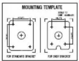
Mounting Template

Operating Instruction
Plastic Anchor: 6 x 30mm (4pcs)
Mounting Screw: 4 x 30mm (4pcs)
Assembly Screw: 4 x 14mm (4pcs)
Torque Wrench: 3mm (1pc)
Wiring Connector: (1pc)
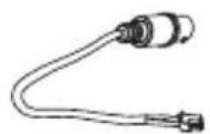
Video Sub-out Cable (1pc)

natural_image
Collection of various screw and pin components, including screws, bolts, and a bent bracket (no text or labels)
Easy Bracket
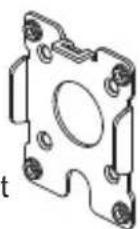
Dimensions


CAUTION
- Extreme care should be taken NOT to scratch the window in front of lens.
- Care should be taken that the cable is NOT damaged, kinked or exposed in a hazardous area.
- Do not point the camera lens directly at the sun or a spot light.
Part Names

Installation Instructions
- Place the mounting template at the installation position and drill the ceiling or wall if needed. (*The easy bracket can not be installed on the ceiling)
- Place the easy bracket on pre-drilled position and attach it using mounting screws (4x30mm). Skip this step when an easy bracket is not installed.
- Route the Power cable to the connecting place. Hook up the camera bracket with the easy bracket as illustrated below.
- Fix the camera bracket through using assembly screws (4x14mm).
- Set the camera's viewing angle and adjust zoom/focus of lens by using the torque wrench.
- Install the sunshield onto the camera unit and tighten the sunshield-bolt.
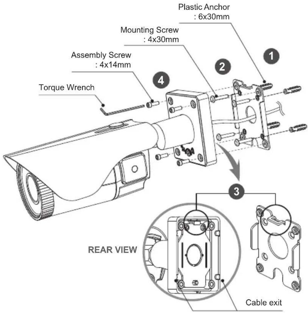
Installation Instructions
Pan & Tilt adjustments
- Unlock the screw on the camera bracket through using the torque wrench supplied - Set the camera's viewing angle then lock the screw on the bracket.
1) Pan limit:
Pan is limited to +/- 90°.
2) Tilt limit:
Tilt is limited to 0°(2°) min 90° max. for wall(ceiling) installation respectively with reference to the wall(ceiling) when the inclination of camera module is 0° , that is, the image is aligned horizontally.


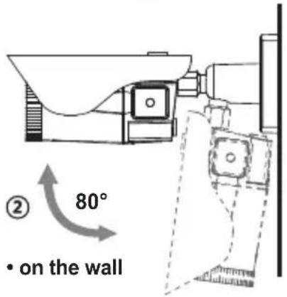
3) Inclination limit
(Horizontal image alignment): Inclination limited to +/-90° max.

Zoom & Focus adjustments
Use the torque wrench supplied.
- Turn the Focus gear to "N"(Near) or " ∞ )(Far) until the sharpest focus is made.
- To widen the viewing angle, turn the Zoom to "W"(Wide) and to obtain a closer view, turn it to "T"(Tele)

flowchart
graph TD
    A["N"] --> B["∅"]
    B --> C["T"]
    C --> D["W"]
    D --> E["ZC"]
    style A fill:#f9f,stroke:#333
    style B fill:#ccf,stroke:#333
    style C fill:#cfc,stroke:#333
    style D fill:#fcc,stroke:#333
    style E fill:#ffc,stroke:#333
Installation Instructions
Installation Instructions
• Make sure the power is removed before the installation.
- Follow this order for applying power.
First connect the low voltage cable (DC12V or AC24V), then plug the AC adapter into AC outlet to avoid damage from the surge voltage with no load.
Power Supply Connections
Camera can work with either 24VAC or 12VDC, dual voltage power.
Primary and secondary grounds are completely isolated to avoid the possible ground-loop problems

※ Attach the Signal Assignment Sticker in a visible spot for wiring reference.

Operating Instructions
Using OSD controller
Setup menu can be accessed and controlled by OSD control joy stick on the side of camera unit. Five commands are available with the joy stick.
The design of OSD could be different according to the Model.


Description of the joystick operation
1) SET Key (●): Access to the menu or enter the setting.
To enter the main menu, press the Set Key down for about 1.5sec
2) UP/DOWN Key (▲/▼): Choose the desired sub-menu and to move the cursor up or down.
3) LEFT/RIGHT Key (◀/▶): Set up the value of the selected menu. Used to adjust the desired menu selection and to move the cursor left or right.
4) '☐' denotes the long press down straightly for about 2 seconds

Description of the D-ZOOM\* adjustment
(*) Works only when OSD menu is inactive.
1) ▲ : Zoom In
2) ▼ : Zoom Out

Description of Video format switch (TVI ↔ CVBS)
1) Selects the video output TVI or CVBS. Default position is TVI.
2) Switching the video format: ▲, ▼, ▲, ▼, ● ( ☑ long push 1\~2 sec.)
Do not power off the camera after switching a video format immediately. It can be cause of crashing a flash memory.
Operating Instructions
OSD menu Startup
Press ‘●’ (OSD menu Joy stick key) down for about 2 seconds to access the setup menu mode.
- RET: Returns to the previous menu.
- EXIT : Exits the menu setting without save.
- SAVE&EXIT : Exits the menu setting with save.
| MENU V3.xx | |
| 1. EXPOSURE | ← |
| 2. LENS | DC ← |
| 3. FOCUS ASSIST | ← |
| 4. SCENE ENHANCE | NORMAL |
| 5. 3D-NR | MID |
| 6. DAY/NIGHT | AUTO ← |
| 7. PICT ADJUST | ← |
| 8. SPECIAL | ← |
| 9. SYSTEM | ← |
| A. EXIT | SAVE&EXIT ← |
Direct Control menu
| MAIN | DEFAULT | DESCRIPTION |
| EXPOSURE | - | Sets SHUTTER MODE, BRIGHTNESS, SENS-UP and AGC. |
| LENS | DC | Sets Lens types. |
| FOCUS ASSIST | - | Sets Focus Adjustments. |
| SCENE ENHANCE | NORMAL | SCENE ENHANCE provides several ways to enhance the video in various environments with settings of NORMAL, WDR, D-WDR, BLC and HLC.NORMAL – Optimized for the normal indoor and outdoor in good lighting condition.WDR – Improves the visibility for bright areas and dark areas by the double capture of image with LONG and SHORT exposures. With WDR ON, the frame rate becomes half by the double capture. WDR level can be selected from LOW, MID and HIGH. Care should be taken to select this mode because video may lose its quality in some environments by over compensation.※CVBS video signal:Connecting 2nd video to CVBS port disables WDR function temporarily. It should be considered when installer adjusts the video with installation monitor via CVBS video signal. |
Operating Instructions
| SCENE ENHANCE | NORMAL | D-WDR – Improves the visibility by compensating the video gain for the dark area. Noise can increase in the dark area accordingly.BLC – Improves the visibility for dark objects by bright back light. Outside area of BLC window can over saturate.BLC has a target window for compensation and its size and position can be set by H-POS, V-POS, H-SIZE and V-SIZE.HLC – Cuts out the bright area with a black mask and excludes it from compensation. Lower HLC LEVEL cuts out video from lower light levels (more sensitive). |
| 3D-NR MID | OFF, LOW, MID and HIGH. | |
| DAY/NIGHT | EXT for IR LED | DAY/NIGHT is used to control the setting during day-time and night-time operation. Select the mode according to the lighting conditions and the camera type. SMART (DYNAMIC) IR can be set to reduce the saturation by strong IR illumination at night in any menu. Setting SMART (DYNAMIC) IR in any menu is identically applied to other menu. Zero(0) turns off SMART (DYNAMIC) IR and High setting decreases the saturation but the corners will be darker accordingly.EXT – DAY or NIGHT is determined by the built-in light photo sensor. Camera with IR LED must be set to EXT.AUTO – Used when DAY or NIGHT is determined by light level through the lens and DAY from/to NIGHT is switched automatically by the scene brightness. D↔N THRESHOLD, D↔N DELY and SMART (DYNAMIC) IR can be set in the menu. When EXPOSURE>AGC is less than 10, DAY/NIGHT AUTO is disabled and forcibly switches to ____(DAY) to avoid malfunction. EXT, B/W (NIGHT) and COLOR (DAY) is independent on AGC level. When EXTERNAL IR LED is used with NON IR LED model, please set to IR LED MODE ON.B/W(NIGHT) – Removes IR cut filter and switches to B/W regardless of light level.COLOR(DAY) – DAY/NIGHT is disabled and outputs color video. |
| PICT ADJUST | Sets WHITE BAL, SHARPNESS, COLOR GAIN, GAMMA, SHADING | |
| SPECIAL | Sets MIRROR/FLIP, PRIVACY, MOTION, PIXEL DEFECT, TITLE SET, DISPLAY, DEFOG, POINTING ZOOM, PRESET ZOOM | |
| SYSTEM | Sets TV SYSTEM, RESOLUTION, COMM.SETUP, LANGUAGE, VIDEO OUTPUT SELECT and FACTORY DEFAULT | |
| EXIT | SAVE & EXIT – Exits the menu after saving the parameters. EXIT – Exits the menu without saving. |
1. EXPOSURE
EXPOSURE
| SHUTTER | AUTO |
| BRIGHTNESS | |:::|:::| 10 |
| SENS-UP | OFF |
| AGC | |:::|:::| 12 |
| RETURN | RET ↓ |
1-1. SHUTTER (default: AUTO)
: Set SHUTTER MODE to AUTO, MANUAL and Flickerless. MANUAL and Flickerless modes disable SENS-UP functions.
- AUTO: Optimizes the video level by controlling the iris and the shutter speed automatically.
- MANUAL: Iris and Shutter can be set to a fixed value.
- Flickerless: Reduces the flicker in video when US(60Hz)/EU(50Hz) mode is used in 50Hz/60Hz fluorescent lighting respectively.
1-2. BRIGHTNESS (default: 10)
: Adjusts the brightness of video(0\~20).
1-3. SENS-UP (default: AUTO)
: A brighter video can be obtained by increasing the exposure time at night with SENS-UP. SENS-UP is the maximum integration of frames by DSS (Digital Slow Shutter) in low light.
- AUTO: SENS-UP is enabled or disabled automatically by the scene brightness. Higher SENS-UP can get brighter video but the slower frame rates with motion blur and more white pixels. If set to AUTO, maximum integration limit for SENS-UP (Slow Shutter) can be set to x2, x4, X8, x16, X32 in SENS-UP menu.
• OFF: Disables SENS-UP.
1-4. AGC (default: 12)
: AGC(0\~20) amplifies the video gain for brighter video but will cause noise and white pixel accordingly. AGC level less than 10 disables AUTO in DAY/NIGHT.
Operating Instructions
2. LENS
Select either DC or MANUAL lens.
Lens MUST be set to DC for the best image when DC iris lens is installed


2-1. DC (default: DEBLUR for None LED type)
: Select lens mode according to installation. INDOOR or DEBLUR for indoor installation according to environment.
- OUTDOOR: Optimized for outdoor environment.
- INDOOR: Optimized for indoor environment.
- DEBLUR: ON enables MOTION DEBLUR to reduce motion blur in certain indoor environments. Noise or color rolling can increase.
2-2. MANUAL (default: NORMAL for None LED type)
: Horizontal wave or bar may be seen when MANUAL is selected and the camera is working under florescent or similar lights. Select NORMAL or DEBLUR.
3. FOCUS ASSIST

Usually cameras are installed in the day time and they often become OUT OF FOCUS at night time and IN FOCUS again the next day.
This problem can occur with any camera regardless of type or manufacturers.
Operating Instructions
FOCUS Adj. menu is a unique and patented feature that helps focus by simulating DAY &NIGHT conditions.
Set zoom first and adjust focus to get best picture while switching between DAY & NIGHT.
- DN DWELL (5s) : ICR switcher switches DAY & NIGHT at the interval of D/N DWELL.
- POP ON FOCUS (OFF) : ON zooms into the center of the picture at 2X for better focusing.
- FOCUSING STATUS (ON) : Shows how exactly focus is set. When blue bar doesn't show up, try the lens focus to NEAR and FAR. The maximum blue bar indicates the best focusing position.
4. SCENE ENHANCE
: Refer to 'DIRECT CONTROL MENU' table.
| MENU | V3.xx |
| 1. EXPOSURE | ← |
| 2. LENS | DC ← |
| 3. FOCUS ASSIST | ← |
| 4. SCENE ENHANCE | WDR ← |
| 5. 3D-NR | MID |
| 6. DAY/NIGHT | EXT ← |
| 7. PICT ADJUST | ← |
| 8. SPECIAL | ← |
| 9. SYSTEM | ← |
| A. EXIT | SAVE&EXIT ← |

• NORMAL (default):
Optimized for normal indoor and outdoor lighting conditions.
• WDR : Select from LOW, MID and HIGH
• D-WDR : Select from LOW, MID and HIGH
- BLC : Set the BLC area by H-POS, V-POS, H-SIZE and V-SIZE.
• HLC : Set the level up to 20
5. 3D-NR (default: MID)
3D-NR is a very sophisticated and powerful time-based noise reduction technology by monitoring the noise for the several video frames and defining and eliminating them consecutively at low light.
Operating Instructions
Higher setting reduces more noise but results in losing sharpness, and tail effects or motion blur may occur.
6. DAY / NIGHT
: Refer to 'DIRECT CONTROL MENU' table.
Default setting are EXT for IR-LED types and AUTO for None IR LED types.


7. PICT ADJUST

7-1. WHITE BAL (default: ATW)
: ATW, ATWext, ONE PUSH and MANUAL are available for the white balance modes.
- ATW: White balance is continuously working along with the color temperature changes in the range of 2,000K\~8,500K.
- ATWext: White balance is continuously working along with the color temperature changes in the range of 1,800K\~11,000K.
- ONE PUSH: White balance works only during • is pressed.
- MANUAL: White balance is fixed to the settings by R_GAIN and B-GAIN. This mode can be used only when the color temperature does not vary.
Operating Instructions
7-2. SHARPNESS (default: 10): Adjusts the sharpness of video(0\~20).
7-3. COLOR GAIN (default: 10): Adjusts the color level of video(0\~20).
7-4. GAMMA (default: 0.5): Adjusts the gamma of video.
7-5. SHADING (default: OFF):
ON enables to compensate the shade caused by wide lens setting.
8. SPECIAL
SPECIAL
| MIRROR/FLIP | OFF |
| PRIVACY | |
| MOTION | OFF |
| PIXEL DEFECT | OFF |
| TITLE SET | |
| DISPLAY | |
| DEFOG | OFF |
| POINTING ZOOM | OFF |
| PRESET ZOOM | OFF |
| RETURN | RET |
8-1. MIRROR/FLIP (default: OFF)
: Reverses the video left and right and/or up and down by MIRROR/FLIP.
• OFF : Normal display without mirroring or flipping
- Hor.: Video is reversed left and right
- Ver. : Video is reversed upside down
- HV : Video is reversed left and right and upside down.
When the video is reversed by Ver. or HV, then the joystick directions are reversed accordingly. This feature is very useful when a camera installed upside down.
8-2. PRIVACY
: 10 Privacy zones which can be enabled individually by ZON DISP are available to mask the video.
- PRIVACY ALL: ON enables all Privacy Zones you set.
- ZONE NUM: Set a number to select a privacy zone from 1\~10.
- ZONE DISP : ON enables to display relevant privacy zone
- H-POS, V-POS, H-SIZE and V-SIZE : Adjust the size and position of zone
- COLOR : Select the color used for masking the zone form eight colors.
- TRANSPARENCY : Defines the transparency for the mask zone.
Operating Instructions
7-3. MOTION (default: OFF)
: MOTION can detect the changes in the motion window and displays the results in blocks and/or a text message.
- SENSITIVITY: Adjusts the detection sensitivity for motion.
Higher value increases the sensitivity to detect small motion easier. Too low of sensitivity will cause erratic detection.
• H-POS, V-POS, H-SIZE and V-SIZE :
Adjust the size and position of the detection window.
- BLOCK DISP : ON enables to display the blocks for the detected area.
- MOTION OSD : ON enables to display a text message, MOVING !!!,
- SMART MOTION ZOOM : ON enables to Automatic Zoom IN/OUT when motion is detected and also enables MOTION OSD to ON.
Area to be zoomed in by SMART MOTION ZOOM can be set at SPECIAL>MOTION> SMART MOTION ZOOM. Adjusting◀,▶ (Joystick) for ZOOM TARGET varies the viewing angle to be zoomed when motion occurs. Set the video left and right and/or up and down by MIRROR/FLIP.
(See "SMART MOTION ZOOM" Section)
* SMART MOTION ZOOM doesn't work in low light condition and BW.
- STAY ZOOMING : Sets the duration time for zooming by Motion.

NOTICE
: SMART MOTION ZOOM does not work at low sensitivity and B/W mode.

CAUTION
: Set the direction of video by MIRROR/FLIP before setting SMART MOTION ZOOM. Otherwise ZOOM TARGET could be different from your intention.
8-4. PIXEL DEFECT (default: OFF)
: Detects and compensates the white pixels which become defective.
Once CALIBRATE is selected, the pixel calibration is initiated with lens closed and can't cancel.
- THRESHOLD : Defines the level of detection.
Be sure to set the value so that the pixels are uniformly blinking over the entire screen. Too low of a value will get bad results because too many pixels are detected as bad pixels and the maximum number of pixels for compensation will be filled by the upper area.
Operating Instructions
- EXECUTE ‘Q’ : Long pressing will execute the pixel calibration for the detected pixels. Menu will exit automatically after compensation.
8-5. TITLE SET
: Camera title(name) can be set and edited up to 15 alpha numeric and symbolic characters from ASCII codes(ENGLISH only). ▲, ▼, ◀, ▶ moves the cursor to next input.
Choose a character and ‘¶’ selects it. The selected characters are added and displayed on the top left Corner and the cursor moves right automatically for next input.
- SP - Space is inserted when pressed ‘●’
- BS – Cursor moves back when pressed ‘●’
- CLR – Clears all the characters on input line when pressed ‘●’.
- POS – To be able to set the title position by ▲, ▼, ◀, ▶ and ●.
8-6. DISPLAY
: Enables or disables the OSD display.
- ID : ON enables camera ID display defined by SYSTEM>COMM. SETUP>CAM ID.
- TITLE : ON enables to display the camera title(name) set by SPECIAL> TITLE SET.
- D-ZOOM RATIO : ON enables to display the zoom ratio on the bottom right corner. DZx.x will display by multiplying the actual digital zoom ratio.
8-7. DEFOG (default: OFF)
- AUTO : Enhance foggy video automatically according to status of scene.
- MANUAL : Sets to enhance foggy video manually regardless of status of scene.
- LEVEL : LOW, MID, HIGH Video quality can be less in normal environments.
8-8. POINTING ZOOM
ON enables to set off-centered location to be the center of zoom H-POINTER, V-POINTER-Able to set the location of zoom center D-Zoom is available DZx1.1\~x8.0 (See page No.22 "POINTING ZOOM")
8-9. PRESET ZOOM
Able to zoom into a preset location using the PTZ functions.
- ZONE NUM : Select Preset zone number 1\~4.
- ZONE VIEW : ON displays selected zone preset view.
- H-POS and V-POS : Adjust the size and position the preset zone.
Operating Instructions
- D-ZOOM RATIO: Set the D-Zoom Ratio from DX 1.1\~DX5.0
- STAYING ZOOMING : Sets the duration time for preset zoom area.
CAUTION
- Set the direction of video by MIRROR/FLIP before POINTING ZOOM setting. Otherwise location of zoom center could be different from your intention.
- Preset Zoom is available with RS-485 model only.
9. SYSTEM
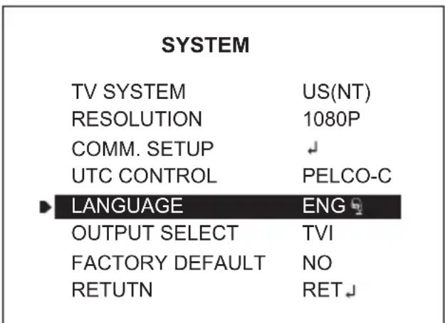
9-1. TV SYSTEM (default: US or EU)
: Selects HDTV standards for US(60HZ) or EU(50HZ). By this selection, 2nd analog video output switches to NTSC or PAL accordingly.
9-2. RESOLUTION (default: 1080P)
: Three resolutions, 1080P/720P(SCALED)/720P(CROPPED) are available. 1080P outputs 1920x1080 video at the frame rate of 30P/25P.
- 720P(SCALED): Image is scaled down from 1080P and outputs 1280x720 video without loss of field of view at the frame rate of 30P/25P.
- 720P(CROPPED): Image is cropped at the center area from the image sensor and outputs 1280x720 at the frame rate of 30P/25P.
Cropped image has narrowed field of view.
9-3. COMM. SETUP
: COMM. SETUP defines the CAM ID, BAUD RATE and PROTOCOL. Data length, stop bit and parity are fixed to 8bit, 1stop bit and no parity bit.
- CAM ID – Assigns the camera ID from 1\~255 for the comm. address.
- BAUD RATE – Select the baud rate from 2400\~115200.
- PROTOCOL – Select the comm. Protocol from PELCO-D/P or VISCA.
- CAM ID – Assigns the camera ID from 1\~255 for the comm. address. - BAUD RATE – Select the baud rate from 2400\~115200. - PROTOCOL – Select the comm. Protocol from PELCO-D/P or VISCA.
Operating Instructions
9-4. UTC CONTROL (default: AUTO)
: Camera can be adjusted through DVR using Up-the-Coax(UTC) communication with PELCO-C protocol. Select AUTO, PELCO-C or OFF
- AUTO : The camera will automatically detect the PELCO-C protocol.
- PELCO-C : Camera can detect PELCO-C protocol only.
[Note]
AUTO only supports the PELCO-C protocol of verified DVRs. If the communication does not work with AUTO well, switch to PELCO-C.
9-5. LANGUAGE (default: ENG)
: 8 languages are available for ENGLISH, JAPANESE, GERMAN, FRENCH, ITALIAN, SPANISH, POLISH and TURKISH. When changing LANGUAGE, select language and press ☑ to load.
9-6. OUTPUT SELECT (default: TVI)
: Selects the video output TVI or CVBS.
[Note]
- Switching the video format : ▲, ▼, ▲, ▼, ● ( long push 1\~2 sec.)
Do not power off the camera after switching a video format immediately. It can be cause of crashing a flash memory. - If set to CVBS video output, UTC Control setting is switched to OFF
9-7. FACTORY DEFAULT(default: NO)
: RECALL 📄 roads and saves the factory defaults.
A. EXIT
A-1. SAVE&EXIT : Save all the setting and exit the main menu
A-2. EXIT : Exit the main menu without save.
Operating Instructions
TIP
(Available with RS-485 model only)
Setting for RS-485 Communication with PTZ Controller
- Enter the MENU : Press buttons 9+5+PSET (PRESET)
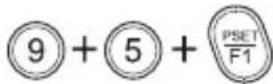
- Set the Preset Zoom: Press buttons 1(or \~4)+PSET (PRESET)

- Move the cursor in the MENU : Moves UP/DOWN/LEFT/RIGHT Joy stick

- Select or Choose value in the MENU : Press button OPEN (IRIS OPEN)

- D-Zoom IN : Press button TELE - D-Zoom OUT : Press button WIDE

- Exit the Preset Zoom mode : Press buttons 3+4+PSET (PRESET)

Detail Function Description
SMART MOTION ZOOM
SMART MOTION ZOOM enlarges the area defined by a yellow window to a full sized image when motion is detected in the black window. SMART MOTION ZOOM window can be re-sized by adjusting D-ZOOM RATIO and moved by H-POINTER and V-POINTER.
UNLIKE the conventional zoom which can zoom in/out the center area of image only, by the flexible zoom location and area, SMART MOTION ZOOM differentiates its usefulness from others.
That is, a conventional camera installed in a corner of the ceiling can zoom the center of the floor in a room and result in losing the image of a door on the side wall. However, SMART MOTION ZOOM can be set to see the door side and zoom in that area without missing the IMPORTANT security point.
Operating Instructions
SMART MOTION ZOOM
| H-POINTER | 10 |
| V-POINTER | 10 |
| D-ZOOM RATIO | MZ2.0 |
| MOTION CHK CUNT | 2 |
| RETURN | RET↓ |
- H-POINTER (10): Moves MOTION ZOOM area(Yellow window) horizontally.
• V-POINTER (10): Moves MOTION ZOOM area(Yellow window) vertically. - D-ZOOM RATIO (MZ2.0): Sets the area size to be digitally zoomed when motion occurs in the black window.
- MOTION CHK COUNT (2) - SMART MOTION ZOOM is activated after the motion in MOTION CHK COUNT are detected in a certain period.
For example, SMART MOTION ZOOM is activated after set # of triggers by motion.
POINTING ZOOM
This camera has a very useful and powerful feature, POINTING ZOOM, which can zoom in/out any area.
POINTING ZOOM is the ability to zoom into an off center location using the PTZ Zoom in/out feature when connected via RS485
Use H-POINTER and V-POINTER to move the Yellow box to set the position of the center of the Zoom.
UNLIKE the conventional zoom which can zoom in/out the center area of image only, the flexible zoom location and area, POINTING ZOOM differentiates its usefulness from others.
That is, a conventional camera installed in the corner of the ceiling can zoom the center of the floor in a room and result in losing the image of door on the side wall. However, POINTING ZOOM can be set to see the door side and zoom in that area without missing the IMPORTANT security point.
Operating Instructions
POINTING ZOOM
H-POINTER
10
V-POINTER
10
RETURN
RET

- H-POINTER (10): Sets the horizontal location of area to be zoomed by POINTING ZOOM.
• V-POINTER (10): Sets the vertical location of area to be zoomed by POINTING ZOOM
* SMART MOTION and POINTING ZOOM VS. Conventional Zoom

natural_image
Interior office scene with a woman walking past a glass table and potted plants (no visible text or symbols)
natural_image
Woman standing indoors near a window with framed certificates on the wall (no visible text or symbols)Smart Motion and Pointing Zoom

natural_image
Interior office scene with a woman walking past a potted plant on a table, no visible text or symbols
natural_image
Office desk with a glass table holding potted plants, framed pictures on the wall (no visible text or symbols)Conventional Zoom
| Detailed Specifications | |
| Imaging Sensor | 1/2.8" Sony Exmor Progressive Scan CMOS Sensor |
| Video Output | HD-TVI by BNC - CVBS by BNC |
| Resolution | 2.1 MegaPixel (1080p / 720p) |
| Effective Pixels | 1920(H) x 1080(V) x 30p |
| S/N Ratio | More than 50dB (AGC Off) |
| Sensitivity | 0.0009 Lux @ (LED Off, AGC 12, DSS x2) / 0 Lux with IR On |
| Lens Type | MegaPixel IR Corrected 2.8-12mm Varifocal |
| Smart Motion Zoom | YES |
| IR Illuminators | 40 850nm IR LEDs |
| IR Range | Over 150 Feet |
| Dynamic Intensity Smart IR LEDs | YES |
| DAY / NIGHT | TDN by dual filter switch |
| White Balance | ATW / ATWext / One Push / Manual |
| WDR | True WDR (Dual Scan) |
| DNR | 3D-DNR |
| Advanced OSD Features | NORMAL, WDR, D-WDR, 3DNR, Dynamic IR, Motion Detection, Privacy Mask, D-Zoom(~8x), Sens-up(x32), Flickerless, BLC/HLC, Defog, Pixel Defect Compensation, Title Set, LSC, Deblur |
| Remote Control | UTC by HD-TVI DVR(Pelco-C) |
| Weather Resistance Rating | IP-68 |
| Operating Conditions | -22°-122°F (-30°-50°C) < 80% RH |
| Input Voltage | 12VDC / 24VAC (Dual Voltage) |
| Power Consumption (12VDC) | 575mA @ 12V (6.9W with LED ON) |
| Power Consumption (24VAC) | 290mA |
| Weight | 2.98 Lbs. (1.35kg) |
| Dimensions (W x H x L) | 4.35" x 4.33" x 10.11" (110.5 x 110 x 256.7mm) |

natural_image
Front view of a VITEK SonyHD audio workstation (no visible text or labels beyond branding)VT-SHP916
SpireHD 16 Channel Real Time Tribrid TVI / AHD / 960H Digital Video Recorder
• Supports High Resolution TVI, AHD, and 960H Cameras
• 16 Video Inputs with 1 HDMI, 2 Spot Monitor Outputs, and 1 VGA output
• H.264 Compression
• Real Time Live Display & Recording
• Supports both Dynamic and Static IP Addresses
• 16 Audio Inputs / 1 Audio Outputs
• 18 Alarm Inputs (16 +1 Panic & 1 Reset) 8 Outputs with 8 Relays
• Supports 6TB Hard Drives
• Supports 5 internal Hard Drives for up to 30TB of internal Storage (5 x 6TB HDD)
• Supports RAID Levels 1 & 5
- Dual Ethernet Ports
- Remote Viewing over the LAN/WAN via Web Browser
- Applications for iPhone, iPad, iTouch and Android Devices
• Mac OSX Client & PC CMS Central Management Software Included
- Panorama (Thumbnail) & "Quick Search" Functions
- Convenient Network Settings Map
• Automatic sending of Health & Event notifications via email
• Control locally via Front Panel Controls, USB Mouse or with the Included IR Remote control
• 2x RS-485 & 1x RS-232 for PTZ Control
- MJPEG Streaming for easy integration with control systems
LIMITED PRODUCT WARRANTY
VITEK products carry a three (3) year limited warranty. VITEK warrants to the purchaser that products manufactured by VITEK are free of any rightful claim of infringement or the like, and when used in the manner intended, will be free of defects in materials and workmanship for a period of three (3) years, or as otherwise stated above, from the date of purchase by the end user. This warranty is nontransferable and extends only to the original buyer or end user customer of a VITEK Authorized Reseller.
The product must have been used only for its intended purpose, and not been subjected to damage by misuse, willful or accidental damage, caused by excessive voltage or lightning.
The product must not have been tampered with in any way or the guarantee will be considered null and void.
This guarantee does not affect your statutory rights.
Contact your local VITEK Reseller should servicing become necessary.
VITEK makes no warranty or guarantee whatsoever with respect to products sold or purchased through unauthorized sales channels. Warranty support is available only if product is purchased through a VITEK Authorized Reseller.
- FEATURES:
- Safety Precaution
- - Warning :
- - Caution :
- NOTICE
- Contents
- Features
- Key Features
- General Description
- Composition
- Dimensions
- CAUTION
- Part Names
- Installation Instructions
- Pan & Tilt adjustments
- 1) Pan limit:
- 2) Tilt limit:
- 3) Inclination limit
- Zoom & Focus adjustments
- Power Supply Connections
- Operating Instructions
- Using OSD controller
- Description of the joystick operation
- Description of the D-ZOOM\* adjustment
- Description of Video format switch (TVI ↔ CVBS)
- OSD menu Startup
- EXPOSURE
- 1-1. SHUTTER (default: AUTO)
- 1-2. BRIGHTNESS (default: 10)
- 1-3. SENS-UP (default: AUTO)
- 1-4. AGC (default: 12)
- LENS
- 2-1. DC (default: DEBLUR for None LED type)
- 2-2. MANUAL (default: NORMAL for None LED type)
- FOCUS ASSIST
- SCENE ENHANCE
- 3D-NR (default: MID)
- DAY / NIGHT
- PICT ADJUST
- 7-1. WHITE BAL (default: ATW)
- SPECIAL
- 8-1. MIRROR/FLIP (default: OFF)
- 8-2. PRIVACY
- 7-3. MOTION (default: OFF)
- 8-4. PIXEL DEFECT (default: OFF)
- 8-5. TITLE SET
- 8-6. DISPLAY
- 8-7. DEFOG (default: OFF)
- 8-8. POINTING ZOOM
- 8-9. PRESET ZOOM
- SYSTEM
- 9-1. TV SYSTEM (default: US or EU)
- 9-2. RESOLUTION (default: 1080P)
- 9-3. COMM. SETUP
- 9-4. UTC CONTROL (default: AUTO)
- 9-5. LANGUAGE (default: ENG)
- 9-6. OUTPUT SELECT (default: TVI)
- 9-7. FACTORY DEFAULT(default: NO)
- EXIT
- TIP
- Setting for RS-485 Communication with PTZ Controller
- Detail Function Description
- SMART MOTION ZOOM
- POINTING ZOOM
- VT-SHP916
- SpireHD 16 Channel Real Time Tribrid TVI / AHD / 960H Digital Video Recorder
- LIMITED PRODUCT WARRANTY
Brand : Vitek
Model : VTC-IRT40
Category : Unspecified