
VT-TTR410 - Unspecified Vitek - Free user manual and instructions
Find the device manual for free VT-TTR410 Vitek in PDF.

| Product Type | HD-TVI Hybrid DVR |
| Brand | Vitek |
| Model | VT-TTR410 |
| Video Inputs | 4 channels TVI (BNC) + 1 channel IP (6 Mbps) |
| Compression | H.264 High Profile |
| Max Recording Resolution | 1080p @ 15fps per channel |
| Total Recording Frame Rate | 120fps at 720p, 60fps at 1080p |
| Video Outputs | VGA (1080p) and HDMI (1080p) |
| Audio | 2-way audio (RCA input and output) |
| Storage | 1 internal SATA HDD up to 4TB |
| Network Interface | RJ45 Ethernet (10/100) |
| Remote Access | CMS software, web browser, iOS/Android apps |
| USB Ports | 2 x USB 2.0 for mouse and backup |
| PTZ Control | RS-485 supporting multiple protocols |
| Power Supply | DC 12V |
| Dimensions | 255 x 42 x 210 mm (10.04 x 1.65 x 8.27 in) |
| Weight | Approximately 1.5 kg |
| Operating Temperature | 10°C to 50°C |
| Humidity | 10% to 90% |
| Included Accessories | Remote control, USB mouse, SATA cable |
| Cleaning Instructions | Clean only with a dry cloth |
Frequently Asked Questions - VT-TTR410 Vitek
User questions about VT-TTR410 Vitek
0 question about this device. Answer the ones you know or ask your own.
Ask a new question about this device
Download the instructions for your Unspecified in PDF format for free! Find your manual VT-TTR410 - Vitek and take your electronic device back in hand. On this page are published all the documents necessary for the use of your device. VT-TTR410 by Vitek.
USER MANUAL VT-TTR410 Vitek
natural_image
Black rectangular electronic device with control panel and ventilation slots (no visible text or symbols)
natural_image
Front view of a black rectangular electronic device with control buttons and indicator lights (no visible text or symbols)
natural_image
Front view of a black HDTV television studio computer with control panel and navigation buttons (no visible text or symbols on device body)FEATURES:
• Full Tribrid Operation with 4, 8, or 16 Channel HD-TVI/Analog BNC Inputs
• 1-Channel (VT-TTR410), 4-Channel (VT-TTR820), or 8-Channel (VT-TTR1620) IP Camera Support
• 30fps @ 720p / 15fps @ 1080p Recording Per Channel
- Simple plug and play, point-to-point connection from camera to DVR
• H.264 Compression
• HDMI & VGA Video Outputs
- 2 Internal SATA2/SATA3 HDD Slots (VT-TTR820/VT-TTR1620) supporting up to 8TB (2 x 4TB HDD) using Advanced HDD Format
• Supports 4TB Hard Drives
• 2-Way Audio
- Pentaplex: Live Display / Record / Playback / Backup / Remote Access
• PTZ Control over RS-485
• Applications for iPhone, iPad, iTouch and Android Devices
- Remote Viewing over the Internet via Web Browser or LAN
• Mac OSX Client & CMS Central Management Software Included
• Supports both Dynamic and Static IP Addresses
• Control locally via Front Panel Controls, USB Mouse, or with the Included IR Remote control
Notes
- Please read this user manual carefully to ensure that you can use the DVR correctly and safely.
- Use only specified power source.
- Do not install this device near any heat sources such as radiators, heat registers, stoves or other devices that produce heat.
- Do not install this device near water. Clean only with a dry cloth.
- Do not block any ventilation openings and ensure proper ventilation around the DVR.
- Do not pull power plug, always power down through main menu
- This DVR is for indoor use only. Do not expose the DVR to rain or moist environments. In case any solid or liquids get inside the DVR's case, please turn off the DVR immediately and have it checked by a qualified technician.
- Do not try to repair the DVR yourself.
- The pictures and screenshots in this manual are only used to explain the usage of our product. The ownerships of trademarks, logos and other intellectual properties related to Microsoft, Apple and Google etc. shall belong to the above-mentioned companies.
● The contents of this manual are subject to change without notice.
Table of Contents
1 Introduction ....5
1.1 FEATURES....5
1.2 FRONT PANEL DESCRIPTIONS....6
1.3 REAR PANEL DESCRIPTIONS 7
1.4 CONNECTIONS....7
2 Basic Operation....8
2.1 STARTUP AND SHUTDOWN....8
2.1.1 Startup 8
2.1.2 Shutdown 8
2.2 REMOTE CONTROL 8
2.3 USING A MOUSE 11
2.4 COMMON BUTTONS 12
3 Wizard Setup....12
4 Live View....13
4.1 LOGIN 13
4.2 LIVE VIEW 14
4.3 SEQUENCE VIEW 16
4.4 MASK VIEW 16
5 Add IP Cameras....17
6 Record....20
6.1 RECORD SETTINGS....20
6.2 MANUAL RECORD 22
6.3 SCHEDULE/CONTINUOUS RECORDING 22
6.4 MOTION BASED RECORDING 23
6.5 SENSOR BASED RECORDING....24
7 Playback....25
7.1 PLAYBACK 25
7.2 PLAYBACK BY TIME SEARCH....26
7.3 PLAYBACK BY EVENT SEARCH 27
7.4 PLAYBACK BY FILE SEARCH....27
7.5 SNAP SETTING AND PLAYBACK BY PICTURE SEARCH 28
7.5.1 Snap Settings.... 28
7.5.2 Playback by Picture Search.... 29
8 Backup 30
8.1 BACKUP 30
8.2 CLIP BACKUP 31
9 Alarm....31
9.1 SENSOR ALARM....32
9.2 MOTION ALARM 33
9.3 VIDEO LOSS ALARM 35
9.4 OTHER ALARM 35
9.5 ALARM OUT 36
9.6 MANUAL ALARM 36
10 P.T.Z....37
11 Network Settings....40
11.1 NETWORK 40
11.2 SUB STREAM 41
11.3 EMAIL....42
11.4 NAT 42
11.5 OTHER SETTINGS 43
12 Other Settings....45
12.1 BASIC CONFIGURATION....45
12.1.1 System 45
12.1.2 Time & Date 46
12.1.3 DST 46
12.2 ADVANCED SETTINGS....47
12.2.1 Reset 47
12.2.2 Import/Export 47
12.2.3 Block/Allow List 47
13 Device Management....48
13.1 USER MANAGEMENT....48
13.1.1 Add, Delete & Modify User 48
13.1.2 Online Users 49
13.1.3 Logoff 50
13.2 DISK MANAGEMENT 50
13.3 VIEW INFORMATION....51
13.4 SHUTDOWN....51
13.5 UPGRADE....51
14 Remote Surveillance....52
14.1 IE REMOTE SURVEILLANCE BY NAT 52
14.1.1 NAT Settings 52
14.1.2 NAT Access....52
14.2 IE REMOTE SURVEILLANCE VIA LAN & WAN....53
14.2.1 LAN 53
14.2.2 WAN....53
14.3 REMOTE SURVEILLANCE THROUGH APPLE PC....54
14.3.1 WAN 55
14.4 REMOTE LIVE VIEW 56
14.5 REMOTE PLAYBACK & BACKUP 58
14.6 REMOTE SYSTEM CONFIGURATION....61
14.7 TOOLS 62
14.8 REMOTE MANAGEMENT 62
15 Appendix A FAQ....63
16 Appendix B Calculate Recording Capacity 67
1 Introduction
1.1 Features
Live Surveillance
● Support VGA/HDMI output
● Support (HD-TVI signal) 1080P/720P, (analog signal) 960H/D1 video inputs & IP cameras up to 8 2MP (model dependent)
● Supports channel security by hiding live display
● Display local record state and basic information
● Supports USB mouse for full control
◆ Compression Format
● H.264 compression with low bit rate
◆ Storage
● Supports SATA HDD with high capacity (up to 4 TB)
◆ Backup
● Support USB 2.0 devices for backup
● Supports saving recorded files in AVI standard format to a remote computer through internet or DVR format
◆ Record and Playback
● Record modes: Manual, Schedule, Motion detection
● Support recycle after HDD full
● Resolution, frame rate and picture quality are adjustable
● Support remote playback in Network Client through LAN or internet
◆ Security
- Customize user right: log search, system setup, two way audio, file management, disk management, remote login, live view, manual record, and playback
● Support event log recording and checking
Network
● Support TCP/IP, DHCP, PPPoE, DDNS protocol
● Support IE, Chrome, Firefox, Safari, browser for remote viewing
● Support NAT Access and QRCODE Scanning
● Support dual stream. Network stream is adjustable independently to fit the network bandwidth and environment
● Support picture snapshot in remote live
● Support remote time and event search, and channel playback
● Support remote full menu setup
● Support mobile surveillance with smart phones, I-Phone & Android OS
● Support CMS to manage multi devices on internet
1.2 Front Panel Descriptions
The following descriptions are for reference only.
Type I:
| Name Descriptions | |
| REC | When recording, light is blue |
| Net | When access to network , the light is blue |
| Power | Power indicator, when connected , light is blue |
| Fn | Switch the resolution of the VGA/HDMI output |
Type II:
| Name | Descriptions | |
| Power | Power Indicator, when connected, light is blue | |
| HDD | The light turns blue when reading/writing HDD | |
| Net | The light turns blue when it is able to access the network | |
| Backup | The light turns blue when backing up files and data | |
| Play | The light turns blue when playing video | |
| REC | Power Indicator, when connected, the light is blue | |
| AUDIO /+ | 1. Adjust audio 2. Increase the value in setup | |
| P.T.Z / - | 1. Enter PTZ mode 2. Decrease the value in setup | |
| MENU | Enter Menu in live mode | |
| INFO | Check the information of the device | |
| BACKUP | Enter backup mode in live | |
| SEARCH | Enter search mode in live | |
| Exit | Exit the current interface | |
 | Manually record | |
| Play/Pause | ||
| Rewind key | ||
| Fast forward | ||
| 1-9 | Input 1~9 to select camera channel | |
| 0/10+ | Input 0/10+ and select camera two digit channel | |
| Direction Key | Change direction | |
| Multi-Screen Switch | Change the screen mode | |
| Enter | Confirm selection | |
| USB | To connect external USB device like USB mouse or USB flash drive | |
1.3 Rear Panel Descriptions

| No. | Name | Descriptions |
| 1 | AUDIO OUT | Audio output |
| 2 | AUDIO IN | Audio input |
| 3 | HD TVI VIDEO IN | (HD-TVI signal) 1080P/720P, (analog signal) 960H/D1 video inputs |
| 4 | HDMI | Connect to high definition display |
| 5 | VGA | Connect to monitor |
| 6 | LAN | Network port |
| 7 | USB | Connect USB storage device or USB mouse |
| 8 | DC12V | DC12V power input |
| 9 | RS485 | A is TX+; B is TX- |
1.4 Connections
- Video Connections
4/8/16 BNC inputs for analog D1, 960H and TVI 720p, 1080P cameras
Video Output: Supports VGA/HDMI video output. Connect to monitor through these video outputs simultaneously or independently.
● Audio Connections
Audio Input:
Audio Output:
- PTZ Connection
Connect PTZs via RS485 interfaces:

Type 1: The B (Tx-) /A (Tx+) interface are used to connect speed dome (PTZ).
2 Basic Operation
2.1 Startup and Shutdown
Make sure that all connections are properly connected. Proper startup and shutdown are crucial to expending the life of the DVR.
① Connect the power.
② The device will boot and the power LED will turn blue.
③ A WIZARD window will pop up and show some information about time zone, time setup, network configuration, record configuration and disk management.
Note: Change Display Resolution by pressing ESC key on DVR/Switch on Remote from VGA to HDMI output
You can power off the device by using remote control or mouse.
By keyboard and mouse:
① Click Menu Button; select Shutdown from pop up window. Unit will start power off sequence by clicking "OK". Press "CANCEL" to return to Menu. Disconnect the power.
2.2 Remote Control
① Use two AAA size batteries.
② Open the battery cover of the remote control.
③ Insert batteries. Please take note of the polarity (+ and -).
④ Replace the battery cover.
Key points to check in case the remote doesn't work.
- Check batteries polarity.
- Replace batteries.
- Check IR controller sensor for any blockage.
- Check the ID of the remote with respect to the HD TVI Hybrid DVR.

| Button | Function | |
 | Power Button | Switch off—to stop the device |
| Record Button | To start recording | |
| -/-- | Input number or choose camera 10+ | |
| Fn1 Button | Not Used | |
| Multi Button | To choose multi screen display mode | |
| Next Button | Manually Sequence Next channel | |
| SEQ | Enter into auto dwell mode | |
| Audio | Enable audio output in live mode | |
| Switch | Switch VGA/HDMI Resolution | |
| Direction button | Move cursor in setup or pan/title PTZ | |
| Enter Button | Confirm the choice or setup | |
| Menu Button | Enter Main Menu | |
| Exit Button | Exit the current interface | |
| Focus/IRIS/Zoom/PT Z | Control PTZ camera | |
| Preset Button | Enter into preset setting in PTZ mode | |
| Cruise Button | Enter cruise setting in PTZ mode | |
| Track Button | Enter track setting in PTZ mode | |
| Wiper Button | Enable wiper function in PTZ mode | |
| Light Button | Enable light function in PTZ mode | |
| Clear Button | Return to the previous Menu | |
| Fn2 Button | Not Used | |
| Info Button | Information about the device. | |
| Control playback.Play/Pause/Stop/ Previous Section/ Next Section/Backward/ Forward | ||
| Snap Button | Take snapshots manually | |
| Search Button | Enter search mode | |
| Cut Button | set the start/end time for backup | |
| Backup Button | Enter backup mode | |
| Zoom Button | Zoom into the image | |
| PIP Button | Enter picture in picture setting mode | |

| Button | Function |
| REC | Record manually |
| Search | Enter search mode |
| MEUN | Enter menu |
| Exit | Exit the current interface |
| ENTER | Confirm the choice or setup |
| Direction button | Move cursor in setup |
| ZOOM | Zoom into the image |
| PIP | Enter picture in picture setting mode |
| ▶▶▶▶▶▶▶▶▶▶▶▶▶▶▶▶▶▶▶▶▶▶▶▶▶▶▶▶▶▶▶▶▶▶▶▶▶▶▶▶▶▶▶▶▶▶▶▶▶▶▶▶▶▶▶▶▶▶▶▶▶▶▶▶▶▶▶▶▶▶▶▶▶▶▶▶▶▶▶▶▶▶▶▶▶▶▶▶▶▶▶▶▶▶▶▶▶▶▶▶> | Control playback. Play/ Pause/ Stop/ Previous Section/Next Section/Backward/ Forward |
| Multi | Choose multi screen display mode |
| Next | Switch between single picture and picture group |
| SEQ | Enter into auto dwell mode |
| INFO | Information about the device like firmware version, HDD information |
Entering password by remote control
① Move the cursor to password box and then press "Enter" button on the remote control to pop up a soft keyboard.
![1 2 3 4 5 6 7 8 9 0 Backspace q w e r t y u i o p [ ] \ a s d f g h j k l ; ' Enter Shift z x c v b n m , . / Esc - =](/content/2026/06/1213778/images/431a014e86d3650f45bc00f23122fdd0c0b059894141dd5163f67e15fbca7867.jpg)
② Move the cursor to "1" on the soft keyboard and then press "Enter" button on the remote control. Next, input "2", "3", "4", "5", "6" separately.
③ Move the cursor to "Enter" button on the soft keyboard and then press "Enter" button on the remote control.
Controlling Multiple Devices by remote control
The default device ID of the HD TVI Hybrid DVR is 0. It's not necessary to reset the device ID when a remote is to be used to control a single device. However when controlling multiple
devices with multiple remote controls, you will need to configure the device ID, please refer to below steps:
① Activate remote control to control the device: Point the IR sensor of the remote control towards the IR receiver on the front panel, press the number 8 key twice on the remote, input device ID of the HD TVI Hybrid DVR to be controlled (Range from: 0-65535; the default device ID is 0) and press ENTER to confirm.
② You can check the device ID of the HD TVI Hybrid DVR from Setup→Basic→System interface. You can also set multiple devices with the same device ID, however this can cause interference if the devices are kept close to each other.
2.3 Using a Mouse
During live:
① Double-click on any camera window to see full screen. Double-click again to return to the previous screen.
② Right click to reveal the control menu on the screen. Right click again to hide the menu.
In Configuration:
① Click to enter a particular option. Right click to cancel the option or return to the previous menu.
② In order to input a value in a particular screen, move cursor to the input box and click.
③ Supports mouse drag. Take setting up motion detection area for example: Click customized, hold down the left button and drag to set motion detection area.
In Playback:
Click to choose the options. Right click to return to live mode.
In Backup:
Click to choose the options. Right click to return to previous picture.
Mouse is the default tool for all operations unless an exception as indicated.
Using Virtual Keyboard
![1 2 3 4 5 6 7 8 9 0 Backspace q w e r t y u i o p [ ] \ a s d f g h j k l ; ' Enter Shift z x c v b n m , . J . Esc - =](/content/2026/06/1213778/images/dec124fe5ac97c5d9e88dcac5db715a0122d1c715c96b3516bf56f5719f0b0b1.jpg)

1\~0 : Digital number.
Enter: Confirm.
Backspace: Delete the previous letter.
Shift: Switch between lower case and upper case.
ESC: Exit.
2.4 Common Buttons
【Default】: Restore the settings to the factory default setting.
【Apply】: Apply and save the settings.
【Copy】: Copy button. Click this button to copy the settings of one channel to other channels quickly.
3 Wizard Setup
The wizard will start once the DVR has loaded, which will guide you through some important settings of your DVR. Follow instructions for quick setup. However, you can skip the wizard by clicking "Exit" button and then go to the setup interface to do detailed setup. To setup using the wizard, follow the steps below:
① Set device Name, Language, Date format, Time format, Time zone, System date, etc. Then click "Next" button to continue.

② Set network. Please set the network according to the actual network situation. Then click "Next" button to continue.

③ Set the disk management. You can format the HDDs and set their properties. Then click "Next" button to continue.
![WIZARD ID Type Size[GB] Free[GB] Status Properties Source SATA 250 200 Normal Read & Wri Local Refresh Format Prev Next Exit](/content/2026/06/1213778/images/71f24c1a7fa3ce84f4208458013e2d934996151a44afecb7e8256b1e804fb04e.jpg)
④ Click "Next" button to complete the wizard setup.
4 Live View
4.1 Login
You can login or logoff the HD TVI Hybrid DVR system. Once logged off the user cannot do any other operation except changing the multi-screen display.

The default username is "admin" and the default password is "123456". Please input the default username and password for the first time to log in.
4.2 Live View

natural_image
Four-panel aerial view of a parking lot with multiple cars parked on grass and trees, no visible text or signage| Symbol | Meaning | Symbol | Meaning |
| Green | Manual record | Red | Sensor Alarm record |
| Yellow | Motion detection record | Blue | Schedule record |
Click right mouse or press ESC button on the front panel and then the control bar will display at the bottom of the screen.

Click the ▲ icon between each Display Mode to select custom channel view interface. Channels can be arranged to any place on grid by left click and drag in the live interface
Screen Mode: You can choose a screen display mode to show live images.
Dwell: Dwell means to display live images from different cameras in a sequence. The images may be displayed as a single channel or in a grid fashion from different cameras. Dwell mode is enabled only when the chosen display mode is not able to display all the available cameras.
E-Zoom: Single channel digital zoom (4X only).
Audio: Enable sound.
PTZ: Click the PTZ button to control rotation position, speed and auto scan of the PTZ.
Snap: Click this button to save a snapshot from live view. These pictures will automatically be saved to the HDD.
Record: Click this button to start/stop recording.
Playback: Click this button to playback last 5 minutes.
You can click Move button and drag it anywhere with the left mouse to move the main menu bar anywhere.
Click Main Menu button to go to main menu interface.
Live View Setup
To set up camera name:
① Go to Main Menu→Setup→Live→Camera Name.

② A software keyboard will pop up by clicking camera name area. Click the letters and (or) digital numbers on the keyboard to input the name you want to display in live image. Up to 32 character, supports spaces.
③ Checkmark the camera name in the show name area. All channels will show the camera name by checking "All" checkbox.
④ Click "Apply" to save the setting.
4.3 Sequence View
You can view channel or channel group in sequence.
![LIVE Live Main Monitor Mask Display Mode 2X2 1/4 Channel 1 Channel 2 Channel 3 Channel 4 Dwell Time[S] 6 Default Apply Exit](/content/2026/06/1213778/images/32ba485a0049c323666a91b5782e30f464abed093b5b52ffc4b8e1c344be7506.jpg)
① Go to Main Menu→Setup→Live→Main Monitor interface.
② Select display mode and channel.
③ Select dwell time. Click ▶ button to set up the previous channel groups of dwell picture. Click ▶ button to set the latter channel groups of dwell picture.
④ Click "Apply" to save the setting.
⑤ Return to the live view interface. Right click to show the menu toolbar. Then enable
Dwell button.
If there is something you don't want to display in the live image. You can set mask. For a given channel a maximum of three areas can be masked.
4.4 Mask View
To set up mask area:
① Go to Main Menu→Setup→Live→Mask interface.
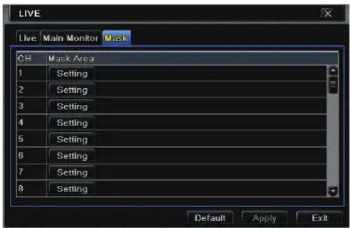
② Click "Setting" button to go to live image.
③ Press and drag the left mouse button to set mask area as shown below.
④ Right click to exit the mask setting interface.
⑤ Click "Apply" button to save the setting.

natural_image
Scenic highway leading toward a snow-capped mountain under a clear blue sky, with green forest and distant hills in the background (no visible text or symbols)Set up Mask Area
To delete mask area:
① Click "Setting" button in the mask interface.
② Select a certain masked area and double click to delete that masked area.
③ Then click "Apply" button to save the setting.
5 Add IP Cameras
This chapter mainly introduces how to connect multiple IP cameras to the HD TVI Hybrid DVR. Once you finish adding IP cameras, you can see the live images through the monitor of the HD TVI Hybrid DVR.
To add IP cameras via LAN:
① Please go to Main Menu→IP Camera tab. Click "Search" button to search the devices in the same local network. (IP Cameras that support Onvif protocol may be added manually.)

② Go to the search tab. Click "Refresh" to refresh the searched devices.

If the IP Camera is not the same address range, click SETUP to modify Information.
Note: If the network of IP cameras and HD TVI Hybrid DVR are in LAN, their IP address must be in the same network segment. For example: If the IP address of HD TVI Hybrid DVR is 192.168.011.007, the IP address of IP camera must be 192.168.011.XXX.

③ Checkmark the found devices and click “OK” button to return to the previous interface. Click “Apply” button and then the added devices will be listed in the device management interface. “Connected” status means connecting the device successfully and you will see the live image.

You may also select the added device and click "Setup" button to modify channel, IP address of the device.

To add IP cameras via WAN:
① Please go to Main Menu→IP Camera tab.
② Click "Add" button to pop up a window as shown below. You need to check "Enable" box, select channel and manufacturer and manually input IP address, server port, username and password of this device.

Note: If the HD TVI Hybrid DVR and the IP cameras you want to add are in WAN, the IP address of the IP camera input here must be a WAN IP.
6 Record
Before recording, please format your HDD first. Go to Main Menu→Disk Management to access disk management settings. In this interface, you can format your disk.
![DISK MANAGEMENT Disk Advanced ID Type Size[GB] Free[GB] Status Properties So SATA 250 200 Normal Read & Wri Lo Refresh Browse Apply Format Exit](/content/2026/06/1213778/images/b80a5d24fb2e56a522346eed99545204dc8c11c708f7946dc707213fae07060b.jpg)
6.1 Record Settings
Go to Main Menu→Setup→Record→Enable for record settings.

① Enable record and audio. Then click "Apply" to save the settings.
② Set record stream. Go to Record Bitrate tab to set record birate as shown below.

Set up rate, resolution, quality, encode and max bit stream according to the actual situation. Then apply the settings.
Resolution: The higher the resolution is, the clearer the image is.
FPS: The higher the frame rate is, the more fluency the video is. However, more storage room will be taken up.
Encode: Including CBR and VBR. CBR means that no matter how active the video resources are, the compression bitrate keeps constant. This will not only facilitate the image quality better in a constant bitrate but also help to calculate the capacity of the recording. VBR means that the compression bitrate can be adjustable according to the change of the video resources. This will help you save more storage room.
Image Quality: When VBR is selected, you need to choose image quality. The higher the image quality you choose, the more bitrate will be required.
MAX Bitrate: When VBR is selected, adjust max bit rate accordingly.
③ Set expiration time, pre-alarm time and post-alarm time.

Expiration Time: Set the expiration time for recorded video. If the set date is overdue, the recorded files will be deleted automatically.
Pre-alarm Time: Set the time in seconds to record before the actual recording begins.
Post-alarm Time: Set the time in seconds to record after the actual recording has finished.
④ Set stamp. Go to Stamp tab. In this tab, you can enable or disable the camera name
and the time stamp on the video and choose a position for the stamp on the screen.

Checkmark camera name and time stamp. Click "Setting" button to set the position of the stamp. You can drag the camera name and time stamp to random positions. Refer to below figures:

Before drag

After drag
⑤ Set recycle record. Go to Recycle Record tab. In this tab, it allows to recycle the HDD space once it is full. If enabled, the system will automatically delete the old records and recycle the space if it is completely utilized.
6.2 Manual Record
A menu toolbar will display by right clicking in the live view mode. Then click button to start recording.

6.3 Schedule/Continuous Recording
The system allows defining schedule for normal recording for seven days a week, 24 hours a day. Every row denotes an hourly timeline for a day. Click the grid to do relevant setup. A highlighted area denotes selected timeline. Operate the following steps to set schedule:
① Go to Main Menu→Setup→Schedule interface.

② Select channel and click
button to add a certain day schedule. Click
button to delete the selected schedule.
If you want to apply the schedule setting of a certain channel to other or all channels, you need to select channel and click "Copy" button.
You can also set week schedule by double clicking in the grid area. This will take you to a dialog box as below.

① Select a day and click "Add" button to schedule start time and end time. Then click to save.
② Select other days and add schedule or copy settings from one schedule to the others under the Apply Settings To item.
6.4 Motion Based Recording
Motion based recording means that the camera will be triggered to record when there is a motion event detected. The setting steps are as follows.
① Go to Main Menu→Setup→Schedule→Motion tab. Choose channel to set schedule for motion based recording. The setting steps are similar to normal schedule recording (See Chapter 6.3 Schedule Recording for details).
② Go to Main Menu→Setup→Alarm→Motion interface. Enable motion alarm and set the motion detection area (See Chapter 9.2 Motion Alarm for details).
![MOTION Motion Schedule CH Enable Holding Time[S] Trigger Area 1 ✓ 10 Setting Setting 2 ✓ 10 Setting Setting 3 ✓ 10 Setting Setting 4 ✓ 10 Setting Setting 5 ✓ 10 Setting Setting 6 ✓ 10 Setting Setting All ✓ 10 Default Apply Exit](/content/2026/06/1213778/images/c4b415358556c857764e69634217436def8b7cf53c19e0131f7f3b6a24ec0043.jpg)
③ Go to alarm handling setting by click "Setting" button under Trigger. Then go to "To Record" tab. You can select the recording channel and click "OK" button to confirm the settings.

④ Set schedule for motion alarm. The setting steps are similar to normal schedule recording (See Chapter 6.3 Schedule Recording for details).
Note: The timelines of these two schedules (schedule for motion based recording and schedule for motion alarm) must match.
6.5 Sensor Based Recording
*Some models may not support this function.
① Set schedule for sensor based recording. Go to: Main→Menu→Setup→Schedule→Sensor. Select channel and then set the schedule. The settings steps of schedule for sensor based recording are similar to normal schedule recording (See Chapter 6.3 Schedule Recording for details).
② Go to Main Menu→Setup→Alarm→Sensor to see the following figure. Enable sensor alarm and choose the sensor type.

③ Go to Alarm Handling tab. Then click "Setting" button under Trigger. An alarm trigger box will pop up. Select "To Record" tab to choose the recording channel and click "OK" button to confirm the settings.

④ Set schedule for sensor alarm. The setting steps are similar to normal schedule recording (See Chapter 6.3 Schedule Recording for details).
Note: The timelines of these two schedules (schedule for sensor based recording and schedule for sensor alarm) must match; otherwise you will not get recording
7 Playback
You can playback the recording by time, picture, event, file and bookmark search.
7.1 Playback
Right Click to pop up the menu toolbar. Click triangle button beside play button to set quick playback time (default 5 minutes). Click on play button to view set minutes in playback mode.
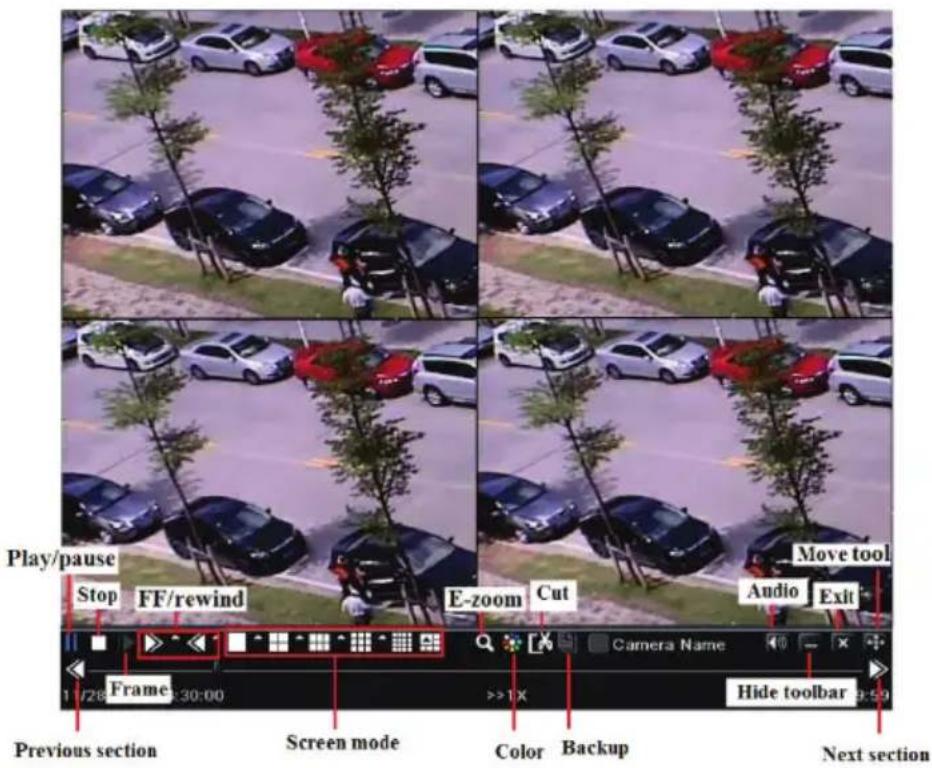
【Previous/next section】: Select the previous hour or the next hour to play recorded files
【FF/Rewind】: Forward /rewind the recording.
【Pause/play】: Pause/play the recording.
【Stop】: Stop the recording.
【Audio】: Click to enable audio. Click again to disable audio.
【Frame】: Click "Pause" button in single channel display mode and then click this button to play the recording frame by frame.
【Screen mode】: Click this button to choose the screen display mode.
【Cut】: After you choose the playback time, click "Cut" to start clipping the recording and click again to complete the clipping.
【Backup】: Insert storage device into the device and then click this button here to see the
clipped recording files in a box. Then click "Start" to back up the recording files into the storage device (see Chapter 8 Backup for more details).
【Exit】: Exit the current interface.
【Move tool】: Click and hold this button. Then drag the mouse to move this toolbar.
7.2 Playback by Time Search
① Go to Main Menu→Search→Time Search.

② Select date and channels on the right hand side and press the "Search" button. A date with highlighted borderline indicates presence of data.
③ Set the start time by clicking a particular grid or by entering the specific value in the start time field.
④ Select the channel display mode and click Play button to play recording. Use the playback toolbar to control the playback.
7.3 Playback by Event Search
① Go to Main Menu→Search→Event Search button.
② Select date and channels on the right hand side. A date with highlighted borderline indicates presence of data.
③ Checkmark Motion, Sensor or All accordingly.
④ Click "Search" button to display the searched event information in the event list box.
⑤ Double check a certain recording file to playback.

7.4 Playback by File Search
① Go to Main Menu→Search→File Management interface.

② Select date and channels. The date with highlighted borderline indicates presence of data.
③ Click "Search" button to display the searched files in the file list box.
④ Use "All" button to lock/unlock or delete all files in the file management column.
⑤ Double click an unlocked item to play.
Lock: Select a file and click "Lock" button to lock this file, after that, that file will not be deleted or overwritten
Unlock: Select a locked file and click "Lock" button to unlock this file.
Delete: Select an unlocked file and click "Delete" button to delete this file.
7.5 Snap Setting and Playback by Picture Search
You need to capture pictures first and then play back by picture search.
- Manual Snap
In the live view mode, right click to dispaly the menu toolbar. Then click 📄 on the menu toolbar to capture the picture.
- Auto Snap
Go to Main Menu→Setup→Record→Snap as shown below. You can set auto snap here.
① Set resolution, image quality, snap time interval and snap number.
② Click “Apply” to save the settings. The system will automatically capture pictures according to the setup.
![RECORD Enable Record Bitrate Time Stamp Recycle Record Snap Resolution GIF Quality Medium Snap Time Interval[S] 2 Snap Number 3 Default Apply Exit](/content/2026/06/1213778/images/431b3cb9ec288df577025cde0a621255d2abe2bfd14848261bf02fe8b2dca80d.jpg)
● Taking Snapshots on Motion Alarm
① Go to Main Menu→Setup→Alarm→Motion. Enable motion alarm and then set the motion detection area (see Chapter 9.2 Motion Alarm for details).
② Go to alarm handling setting by click "Setting" button under Trigger. Then checkmark the snapshot channel and click "OK" button to confirm the settings.
③ Set schedule for motion alarm. The setting steps are similar to normal schedule recording (See Chapter 6.3 Schedule Recording for details).
④ Click "Apply" to save the settings. The picture will be automatically captured once a motion alarm happens.
● Taking Snapshots on Sensor Alarm
Some models may not support this function.
① Go to Main Menu→Setup→Alarm→Sensor. Enable sensor alarm and choose the sensor type.
② Go to Alarm Handling tab. Then click "Setting" button under Trigger. An alarm trigger box will pop up. Then select the snapshot channel and click "OK" button to confirm the settings.
③ Set schedule for sensor alarm. The setting steps are similar to normal schedule recording (See Chapter 6.3 Schedule Recording for details).
④ Click “Apply” to save the settings. The picture will be automatically captured once a sensor alarm happens.
① Go to Main Menu→Search→Image tab.
② Select data and channels on the right hand side.
③ Press "Search" button to search for a recorded image.
④ Once an alarm image has been identified, the user can double click the image to play recording.

8 Backup
You can use a USB storage device (Thumb Drive, removable HDD, USB DVD writer) to do backup. There are two types of backup--Backup and Clip Backup.
8.1 Backup
① Go to Main Menu→Backup.

② Set the start & end time, select channels and click "Search" button to display the searched data in the data backup list box.
③ Select a required file or checkmark "All" to select all data files. Click "Backup" button to display backup information window.
![BACKUP INFORMATION Start Time 03/04/2013 00:00:00 End Time 03/04/2013 23:59:59 The Number Of Files 8 Size[GB] 1.008 Storage Media USB-1 Free[GB] 0.000 Backup Player Save File Type DVR 0 % Disk Cleanup Start Cancel](/content/2026/06/1213778/images/26ee2fa8ddb41befb569e49e1a8c21d80efbf4d640373e7d08018e41330c5042.jpg)
④ In the backup information interface, you can check the relevant information of backup files, such as, storage type, save file type, etc. Then click "Start" button to start backup.
Note: If the backup files are saved in DVR format, please check backup player. Only this player can play these files in DVR format. If the backup files are saved in AVI format, you can play these files with common media player.
8.2 Clip Backup
You can cut the recording file and do a backup in the playback interface. The setting steps of clip backup are as below:
① Insert USB storage device into the DVR.
② In the playback mode, click 📄 button to set the start time. Then click this button again to set the end time.

③ Click button to see a backup window as shown in the above-mentioned figure. Select the storage type and save file type. Then click "Start" button to start backup.
9 Alarm
Alarm settings include sensor alarm, motion alarm, video loss alarm, and alarm out
setting.
9.1 Sensor Alarm
Some models may not support this function. Operate the following steps to configure sensor based alarm:
① Go to Main Menu→Setup→Alarm→Sensor→Basic tab.

② Enable channels by checking the checkboxes beside the desired channels.
③ Set the alarm type according to triggered alarm type. Two options: NO and NC.
④ Click "Apply" button to save the setting.
⑤ Go to Alarm Handling tab. Select hold time.
![SENSOR Basic Alarm Handling Schedule CH Holding Time[S] Trigger 1 10 Setting 2 10 Setting 3 10 Setting 4 10 Setting 5 10 Setting 6 10 Setting All 10 Setting Default Apply Exit](/content/2026/06/1213778/images/ad8b818f74824cfd77f5ce4a7ee6b1048bf43c388f973e92fd7743004be499a7.jpg)
⑥ Click "Setting" button to pop up a dialog box as shown below.

Buzzer: If selected, the local buzzer would be activated on an alarm.
Show Full Screen: If selected, there will pop up the chosen channel on the monitor on an alarm trigger.
To Alarm Out: If selected, this would trigger external relay output on an alarm.
Email: If selected, the HD TVI Hybrid DVR will send an email alert to the preconfigured email address in case of a sensor based alarm from the particular input.
Snap: If selected, the system will snap images of the checked channels on an alarm and save them in the HDD automatically.
⑦ Go to "To Record" tab. Select recording channels. It would be recorded in case of an alarm. Click OK button to save the setting.
⑧ Go to "To PTZ" tab. Set preset, cruise and track options for a PTZ in case of a sensor based alarm. Single or multiple PTZ units could be programmed to perform this function on the same alarm.
⑨ Go to “Schedule” tab. The setting steps for schedule for sensor based alarm are similar to normal schedule setup. You can refer to Schedule Recording for details. This step is very important for sensor alarm. Even if you have enabled the sensor alarm for all channels and set up the trigger, you will not see the result of sensor alarm if no schedule is added.
If you have set schedule for sensor based recording in the same timeline, recordings can also be triggered.
9.2 Motion Alarm
Operate the following steps to configure motion based alarm:
Motion alarm includes two sub menus: motion and schedule. The steps to set motion alarm are as follows:
① Go to Main Menu→Setup→Alarm→Motion.
![MOTION Motion Schedule CH Enable Holding Time[S] Trigger Area 1 ✓ 10 Setting Setting 2 ✓ 10 Setting Setting 3 ✓ 10 Setting Setting 4 ✓ 10 Setting Setting 5 ✓ 10 Setting Setting 6 ✓ 10 Setting Setting All ✓ 10 Default Apply Exit](/content/2026/06/1213778/images/e08799255cd11803706e3c145e3b9fdabf89c5ec1838668da798b7f949ac05c9.jpg)
② Enable motion alarm, set alarm hold time which refers to the time utill which the system will wait for further detection of motion. e.g. If the holding time is set to 10 seconds, once the system detects motion, it will go to alarm but would not detect any other motion alarm (specific to channel) until 10 seconds. If there is other motion detected during this period it is considered it as continuous movement, otherwise it will be considered as a single detection.
③ The setup steps of motion trigger are similar to “Alarm Handling” (See Sensor → Alarm Handling setting for more details).
④ After clicking Area button, a dialog box will pop up as below.

natural_image
Highway with curved road and greenery, viewed through a grid overlay (no text or symbols on the main image)⑤ In the Area interface, you can drag slide bar to set the sensitivity value (1-8). The higher the value the more sensitive it is to motion. Since the sensitivity is influenced by color and time (day or night), you can adjust its value according to the particular conditions. Left click the grid and drag to delete area. Click 🏠 icon to set the whole area as detection area. Click 🏠 on to clear the set detection area. Click 🏠 icon to test the sensitivity as per the particular conditions. Once motion is sensed, it displays a figure icon. Click 🏠 icon to save the setting. Click ✕ icon to exit the current interface.
icon to clear the existing field and set fresh.
⑥ Select "All" to set the same settings for all channels.
⑦ Click "Apply" button to save the setting.
⑧ Go to Schedule tab. The setting steps for schedule motion based alarm are similar to normal schedule setup (see Chapter 6.3 Schedule Recording for more details).
9.3 Video Loss Alarm
This DVR can be set up to detect video loss. The setting steps are as follows:
① Go to Main Menu→Setup→Alarm→Video Loss.
② The setup steps for video loss trigger are similar to “Alarm Handling” (See Sensor → Alarm Handling setting for more details).

9.4 Other Alarm
This tab gives a choice to configure alarm for Disk Full, IP Conflict, and Disconnect event, Disk Attenuation or Disk Lost.
① Go to Main Menu→Setup→Alarm→Other Alarm.

② Use the dropdown menu and select the event or the alarm.
③ Check the required trigger options.
If the selected event is "Disk Full", then use the drop down box for "Disk Shortage Alarm" to choose a threshold value for remaining HDD space. If the threshold value is reached, the system will trigger the Disk Full Alarm.
④ Click "Apply" to save the setting.
9.5 Alarm Out
Some models may not support this function.
To set up alarm out:
① Go to Main Menu→Setup→Alarm→Alarm Out.
![ALARM OUT Alarm Out Schedule Buzzer CH Relay Name Holding Time[S] 1 ALARM OUT 1 10 2 ALARM OUT 2 10 3 ALARM OUT 3 10 4 ALARM OUT 4 10 All 10 Default Apply Exit](/content/2026/06/1213778/images/2971dc4653089b09b55578ceddbedab29fdd4bf44306281f24bee741862723b8.jpg)
② Input relay name and select hold time.
③ Go to Schedule tab. The setting steps for schedule for alarm out are similar to normal schedule setup (see Chapter 6.3 Schedule Recording for details).
To set up buzzer:
① Go to Main Menu→Setup→Alarm→Alarm Out→Buzzer.
② Checkmark Buzzer and set buzzer alarm hold time. This would trigger the buzzer when the system is in alarm.
Note: The alarm out and buzzer must be enabled and their schedules must cover the schedule of other alarm types, like sensor/motion alarm, so that the triggered alarm out and buzzer can take effect on an alarm.
9.6 Manual Alarm
Some models may not support this function. Go to Main Menu→Manual Alarm as shown below.

Choose alarm out and click "Alarm" button to trigger alarm manually. Click "Clear" button to clear the alarm.
10 P.T.Z
Before you can control the speed dome, please make sure the speed dome is connected to the DVR. P.T.Z configuration includes two submenus: serial port and advanced.
Serial port settings are as follows:
① Go to Main Menu→Setup→P.T.Z→Serial Port interface.
② Select “Enable” and set up the address, baud rate and protocol according to the settings of the speed dome.
③ Select "All" to set the same settings for all channels.
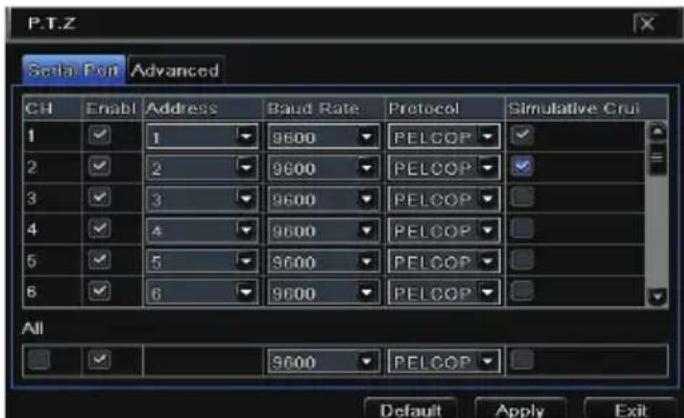
【Address】: The address of the PTZ device.
【Baud rate】: Baud rate of the PTZ device. Range form: 110, 300, 600, 1200, 2400, 4800, 9600, 19200, 34800, 57600, 115200, 230400, 460800, 921600.
【Protocol】: Communication protocol of the PTZ device. Range from: NULL, PELCOP, PELCOD, LILIN, MINKING, NEON, STAR, VIDO, DSCP, VISCA, SAMSUNG, RM110, HY, N-control.
【Simulative Cruise】: If enabled, no matter whether the PTZ device supports cruise or not, the presets will cruise.
Advanced settings include preset setting, cruise (TOUR) setting and track setting. Go to Main Menu→Setup→P.T.Z→Advanced.

To set up preset:
① In the Advanced interface, click preset "Setting" button to see a dialog box.

② In the preset setting tab, enable preset, set the preset name and then click preset "Setting" button.
③ Control the dome by rotating up, up left, down, right down, left, left down, right and up right and adjust the rotate speed and the value of zoom, focus and iris of the dome.
④ Select the preset No. of the preset point. Click button to enable the PTZ wiper and click button to enable the PTZ light.

Note: PTZ must support wiper and light button and these two buttons are only available when selecting PELCO-P or PELCO-D.
⑤ Click Save button to save the setting. Click - icon to hide the tool bar. Right click to view this bar again. Click ✗ icon to exit the current interface.
⑥ Return to the Advanced-Preset Setting interface and click OK button to save the setting.
To set up cruise:
① In the Advanced interface, click cruise Setting button to see a window as shown below.

② Click Add button to add cruise line in the list box (8 cruise lines can be added at most).
③ Select a cruise line and click Setup button to see a dialog box as below.

④ Click Add icon + to set the speed and time of preset point. Select a preset point and then click Delete icon 📋 to delete that preset point. Click Modify icon 🔒 to modify the setting of a preset point. User can click ↑ ↑ ↓ ↓ those icons to adjust the position of preset point. Click Preview button to preview the cruise line. Click OK button to save the setting.
To set up track (Pattern):
① In the Advanced interface, click track "Setting" button to see a dialog box as below.
② Control the dome by rotating up, up left, down, right down, left, left down, right and up right and adjust the rotate speed and the value of zoom, focus and iris of the dome.
③ Click Start Record button to record the track of PTZ. Click it again to stop record.
④ Click Start track button to play recorded track. Click this button again to stop playing.
⑤ Click ✗ icon to exit the current interface. Then click "Apply" to save the setting.


11 Network Settings
Network Settings includes six submenus: network, sub stream, Email, server, NAT and other settings. Network settings must be configured if the device is used for monitoring over network.
11.1 Network
To set up network:
① Go to Main Menu→Setup→Network→Network tab.

② Set HTTP port. The default HTTP port is 80. If the value is changed, you shall add the port number when typing IP address in IE address. E.g. If HTTP port is set to 82 and IP address is http://192.168.11.61, you should input http://192.168.0.61:82 into IE browser.
③ Set server port. The default server port is 6036.
④ Connect internet. There are three ways to connect internet.
If you have a DHCP server running and would like your device to automatically obtain an IP address and other network settings, check the checkbox beside "Obtain an IP address automatically". Then the device will distribute IP address, subnet mask, and gateway IP and DNS server.
If you want to configure your own settings, disable "Obtain an IP address automatically" item and input the IP address, subnet mask, gateway IP and DNS server.
If you connect internet through PPPoE, disable "Obtain an IP address automatically" item and check PPPoE checkbox and then enter username and password. Once the setup is completed, your device will automatically dial up into your network.
⑤ Test the effectiveness of the network by clicking "Test" button after you set up the network.
⑥ If the network is connected, please click "Apply" button to save the setting.
11.2 Sub Stream
To set up sub stream:
① Go to Main Menu→Setup→Network→Sub Stream interface.
② Select fps, resolution (CIF Only), and quality, encode and max bit rate.
③ Select "All" to set the same settings for all channels.

11.3 Email
To set up Email:
① Go to Main Menu→Setup→Network→Email interface.

② Set SMTP Server and port.
SMTP Server/Port: The name and port number of SMTP server. You can set up SSL check (such as Gmail) according to actual needs.
③ Set sender's address and password.
④ Set receiver's email address and click "Test" button to test the validity of the mailbox.
Attaching image: If selected, the system will attach images when sending emails.
11.4 NAT
① Go to Main Menu→Setup→Network→NAT interface.
② Enable NAT and input the NAT Server (The default NAT Server is www.autonat.com).
③ Click "Apply" to save the settings.

11.5 Other Settings
If your device is set to use PPPoE as its default network connection, you may set up DDNS to be used in connection. The setting steps are as follows:
① Enable DDNS server and then select the DDNS server type.
② Enter user name, password and host domain name of the registered website.
③ Click "Test" button to test the effectiveness of the relevant information.
④ Click "Apply" button to save the setting.
![NETWORK Network Sub-stream Email Server NAT Ozone Settings DDNS DDNS Type www.dvrdydns.com User Name Password Host Domain DDNS Update [Hours] 3 UPnP Test Default Apply Exit](/content/2026/06/1213778/images/d91ce2e549e96d49a3259d42614d59ed5444bc33edd76f7f6ba7388c91d19a12.jpg)
Note: The domain name selected by user is a unique domain name of the HD TVI Hybrid DVR. User should logon the website provided by the server supplier to register a user name and password and then apply for a domain name online. After the successful application, user can access the device from the IE client by inputting that domain name.
You can also quickly register the domain name in this interface.
① Set the IP address manually in the network tab and then click "Other Settings" tab.
② Check "DDNS".
③ Select "www.autoddns.com" in DDNS Type column as shown above.
④ Enter the host name that you would like to use.
⑤ Click "Register" to register the domain name. When the successful prompt pops up, it means you are successfully registering your domain name.

UPnP settings:
You can use UPnP function to enable the fast connection of the DVR to WAN via router without port mapping. Before setting UPnP, please configure the correct local IP address, subnet mask, gateway and DNS according to the router. Make sure the HTTP port and data port are correctly set. Make sure the router supports UPnP function.
Please enable UPnP both in the HD TVI Hybrid DVR and the router.
● Domain name Registration (Take www.dvrdydns.com for example)
① Input www.dvrdydns.com in the IE address bar to visit its website. Then click "Registration" button to register as shown below.

② Create domain name.

③ After you successfully request your domain name, you will see your domain in the list.

- Application
① Go to Main Menu→Setup→Network→Other Settings, checkmark DDNS, select "dvrdydns" at the DDNS Sever pull down list box and input user name and password.
② Map the server port and IP address in the router (if the user enables UPnP function, he can skip this step). Click Save button to save the setting.
③ Login IE browser and input registered domain name "http://www.xxx.dvrdydns.com", connect to the IE client.
12 Other Settings
12.1 Basic Configuration
Basic configuration includes three sub menus: system, date & time and DST.
① Go to Main Menu→Setup→Basic→System interface.
![BASIC System Date & Time DST Device Name EDVR Device ID 0 Video Format NTSC Password Check ✓ Show System Time ✓ Max Online Users 10 Video Output VGA 800X600 Language English Logout After [Minutes] Never Default Apply Exit](/content/2026/06/1213778/images/c0c065f1a3445cf9ca7d3734aa35194ef9e042f11d25218614aea111cee03d05.jpg)
② In this interface you can set up the device name, device ID, video format, max network users, VGA resolution, language and so on. The definitions for every parameters display are as below:
Device Name: The name of the device. It may display on the client end or CMS that help user to recognize the device remotely.
Device ID: This ID is used to map the device with IR remote controller and speed dome cameras.
Video Format: Two modes: PAL and NTSC. User can select the video format according to that of camera.
Password Check: If this option is enabled, the user would need to input the user name and the password for performing corresponding operations.
Show System Time: If selected, the current time will be displayed during live monitoring.
Max Online Users: To set the max number of concurrent user logins in the HD TVI Hybrid DVR.
Video Output: The resolution of live display interface.
Language: Set up the menu language.
Note: After changing the language and video output, the device needs to login again.
Logout After (Minutes): A user can set up the screen interval time (30s, 60s, 180s, 300s). If there is no operation within the set period, the device will auto logout and return to login interface.
Show Wizard: If selected, the GUI would launch the startup wizard on every boot, allowing the user to do basic setup.
No Image When Logout: If selected, there will be no image showing when logging out.
Adjust CVBS Video Out: If selected, the device needs to login again for adjusting CVBS video output automatically.
① Go to Main Menu→Setup→Basic→Date & Time interface.

② Set the date format, time format, time zone in this interface; checkmark "Sync time with NTP server" to refresh NTP server date. You can also adjust system date manually.
③ Click "Apply" button to save the setting.
① Go to Main Menu→Setup→Basic→DST interface.
![BASIC System Date & Time DST Daylight Saving Time Time Offset [Hours] 1 Mode Week Date From January The 1st Sunday 00 : 00 : 00 Until January The 1st Default Apply Exit](/content/2026/06/1213778/images/18ae05ff68c691624e697bd71dd0237371250605f97825214853f4c35aa322b3.jpg)
② In this interface, enable daylight saving time, time offset, mode, start & end month/week/date, etc.
③ Click "Apply" button to save the setting.
12.2 Advanced Settings
Advanced configuration includes three submenus: reset, import/export and block/allow list.
Restore the DVR to factory default settings.
You can export the data files into a mobile storage device as backup function, and then import specified data files from mobile storage device to the HD TVI Hybrid DVR.

Here authorized user can prohibit computer users within a certain IP address range from accessing to the HD TVI Hybrid DVR or allow computer users within a certain IP address range to access the HD TVI Hybrid DVR. For example, if an admin user doesn't want computer users within IP address range from 192.168.000.002 to 192.168.000.004 to access the HD TVI Hybrid DVR, he can checkmark Block list option, and then input such IP
address range. If it is required that computer users within a certain IP address range access the HD TVI Hybrid DVR, they can checkmark Allow List option and then do the required configuration.
13 Device Management
13.1 User Management
To add user and set up user authority:
① Go to Main Menu→Setup→Users.

② Click Add button to display a dialog box as below.

③ In General tab, input username, password and select user type. You can also check "Binding PC MAC Address" and input this address.
Note: When the default value of binding PC MAC Address is 0, the user is not bound with the specified computer. If the bind option is used, the user would be able to log into the HD TVI Hybrid DVR only through the specific computer (carrying that MAC address).
④ Click "OK" to save the settings.
⑤ Select Authority tab and then assign the operation rights for particular user.
⑥ Click "OK" to save the settings.

To delete user:
① Go to Main Menu→Setup→Users interface.
② Select the added user you want to delete and then click "Delete" button.
To modify user:
① Go to Main Menu→Setup→Users interface.
② Select the added user you want to modify and then click "Modify" button to do the relevant operation.
To change user password:
① Go to Main Menu→Setup→Users interface.
② Select the added user you want to change its password and then click “Change Password” button.
This function allows you to check how many users are accessing the device and help the administrator to disconnect the online user.
Go to Main Menu→Information→Online Users interface.

【Refresh】: Refresh the current online user.
【Disconnect】: Set the time, choose the online user and click “Disconnect” button. Then this user will be prohibited accessing the device within the set time. After that time, the user can access the device by clicking “Refresh” button or logging in again.
If you want to change the login account, you can click Main Menu→Logoff.
13.2 Disk Management
Click Main Menu→Disk Management to go to disk management as shown below.
![DISK MANAGEMENT Disk Advanced ID Type Size[GB] Free[GB] Status Properties So SATA 250 200 Normal Read & Wri Lo Refresh Browse Apply Format Exit](/content/2026/06/1213778/images/49bcd41e3e16d52767890aac364d7d18a0e6e2681b814868245270cae15c8b0a.jpg)
To format the disk:
① Go to disk management interface.
② Click "Refresh" button to refresh the disk information in the list box.
③ Select a hard disk and click Format button to start format.
Note: All recorded files in the hard disk will be lost after formatting.
To check other information of disk:
After you go to Disk Management→Advanced tab, you can check model, S/N, firmware, health status of the disk in this interface. You also can monitor the temperature, internal circuit, dielectric material of the disk, analysis the potential problems of the disk and warn so as to protect its data.
13.3 View Information
Go to Main Menu→Information interface as shown below. In this interface, you may check the information of system, event, log, network, online users, record and QRCODE.

Click “System” to check the hardware version, MCU version, kernel version, device ID, etc. Click “Event” to search for events like motion, sensor and video loss. The utility provides an interface to have a date based and a channel based search. This report can further be saved on a USB flash drive as an html file using the export button.
Click "Log" to search for relevant logs as per set date and event which include Operation, Setup, Playback, Backup, Search, Check Information and Error. This report can further be saved on a USB flash drive as an html file using the export button.
Click "Network" to check relevant parameters of network.
Click "Online Users" to check the details of the connected online users.
Click “Record” to check resolution, fps and record status including sensor alarm recording, motion recording, manual recording or schedule recording.
Click "QRCODE" to check the QRCODE. You can quickly access the mobile client by scanning QRCODE.
13.4 Shutdown
Click Main Menu→Shutdown to pop up a system shutdown window. Click "OK" to confirm shutdown.
13.5 Upgrade
At present, it only supports USB update. Get the software from http://vitekcctv.com/Downloads.asp when there is a new software version.
The setting steps are as follows:
① Copy the upgrade software into a USB storage device.
② Connect the USB flash drive to the USB port.
③ Go to Main Menu→Upgrade tab. You will see the upgrade software name displaying in the upgrade list box.
④ Select that software and then click Upgrade button. The system will be upgraded automatically.
14 Remote Surveillance
14.1 IE Remote Surveillance by NAT
In order to access the device remotely over LAN/WAN, the network should be set up accordingly.
① The HD TVI Hybrid DVR shall be powered on and connected to the network.
② Go to Main Menu→Setup→Network→Network. You can obtain the IP address, Subnet Mask and Gateway automatically. You can also manually input them according to the actual network situation.
③ Set the preferred or alternative DNS Server (Please refer to 5.6.1 Network for details).
④ Go to Main Menu→Setup→Network→NAT tab.
⑤ Enable NAT and input the NAT Server (The default NAT Server is www.autonat.com).
⑥ Click "Apply" to save the parameters (Please refer to NAT for details).
After finishing the NAT settings, you can enter the NAT Server on the PC. (Input http://www.autonat.com to go to the IE client.) First time accessing the NAT, the network will download the ActiveX automatically.
Note: If you cannot download and install ActiveX, please refer to FAQ Q8.
After installing ActiveX successfully, it will pop up a login box:

Serial No: The MAC address of the HD TVI Hybrid DVR (Go to Main
Menu→Information→Network to check the MAC address of the HD TVI Hybrid DVR).
User Name: The login username of HD TVI Hybrid DVR. The default username is admin.
Password: The login password of HD TVI Hybrid DVR. The default password is 123456.
14.2 IE Remote Surveillance via LAN & WAN
In order to view the HD TVI Hybrid DVR from a network it must be connected to a LAN/WAN. The network setup should be done accordingly.
① Go to the HD TVI Hybrid DVR's Main Menu→Setup→Network tab to input IP address, Subnet Mask, etc. If using DHCP, please enable DHCP in both the HD TVI Hybrid DVR and the router.
② Enter Record Setup to set network video parameters like resolution, frame rate etc.
③ Open IE on a computer on the same network. Input the IP address of the HD TVI Hybrid DVR in IE address bar and press enter.
④ IE will download ActiveX component automatically. Enter the username and password in the subsequent window (the default username is admin; the default password is 123456).
Notice: If HTTP port is not 80, add the port number after IP address. For example, set HTTP port as 82, input IP address like 192.168.0.25:82.
There are two ways for the HD TVI Hybrid DVR to connect to internet.
1. Connect the device to internet through router or virtual server.
① Go to Main Menu→Setup→Network interface to input IP address, Subnet Mask, etc. If using DHCP, please enable DHCP in both the HD TVI Hybrid DVR and router.
② Forward IP address and port number in Virtual Server setup of the router or virtual server. Configure the firewall to allow accessing the HD TVI Hybrid DVR. (If you have enabled the UPnP function in both the HD TVI Hybrid DVR and router, you can skip this step.)
③ If users want to utilize dynamic domain name, please apply for a domain name in a DNS server supported by the HD TVI Hybrid DVR or router. Then add to the HD TVI Hybrid DVR or router.
This unit supports www.meibu.com, www.dyndns.com, www.no-ip.com and mintDNS type.
④ Open IE browser, input IP address, or dynamic domain name and enter. If HTTP port is not 80, add the port number after IP address or domain name.
⑤ IE will download ActiveX automatically. Then a window pops up and asks for user
name and password. Input name and password correctly, and enter to view.
Note: If you cannot download and install ActiveX, please refer to FAQ Q8.
2. Connect the device to internet directly.
① Go to Main Menu→Setup→Network interface to enable PPPoE and then input user name and password received from your ISP. Next, click "Apply". The HD TVI Hybrid DVR will connect to the server and will give a confirmation message.
② When accessing the remote interface of the HD TVI Hybrid DVR, user can input WAN IP to access directly (user can go to Main Menu→Information→Network interface to check IP address). The browser will download Active X control.
③ The following setting steps are as the same as ④ and ⑤ in Point 1.
14.3 Remote Surveillance through Apple PC
① After starting Apple computer, click Apple icon. The following window will pop up. Please select "System Preferences"→ "Internet & Wireless"→ "Network".

② Go to Network interface and then click “Ethernet Connected” to check the internet connection of Apple PC.

③ After acquiring the IP address, Subnet Mask and so on, please go to Main Menu→Setup→Network interface to manually input IP address, Subnet Mask and Gateway according to the configuration of PC. The network segment should be the same as the PC. If using DHCP, please enable DHCP in the HD TVI Hybrid DVR and
route r.
④ After the above information is completed, you can enter LAN IP and HTTP port in the Safari browser. For example: input http://192.168.1.100:81(here 192.168.1.100 is LAN IP of HD TVI Hybrid DVR, 81 is the http port of the device), and click “” button. Then the browser will download WebkitPlugin control as shown below:

⑤ Click ↓ icon and then select the Active X control, the welcome interface will be shown. Click “Continue”→“Install” button, the following window will pop up:

⑥ Input the name and password of Apple PC and then click "OK" to install this WebkitPlugin control.
⑦ After finishing installing the WebkitPlugin control, please quit the Safari browser. Right click Safari icon on the desktop and then select "Quit" button to quit the browser. Then restart Safari browser. Input the IP address and http port to go to the login interface of the device.
There are also two ways for the device to connect to Internet.
1. Connect the device to internet through router or virtual server.
① The network setups are the same as step one to step four of point 1 on WAN of IE remote surveillance.
② Enter WAN IP and http port in the Safari browser to install the WebkitPlugin control.
2. Connect the DVR to internet directly.
① The network setups are the same as step one of point 2 on WAN of IE remote
surveillance.
② Enter WAN IP and http port in the Safari browser to install the WebkitPlugin control.
14.4 Remote Live View

Symbol and function definitions:
| 1 | Channel indicator | 2 | Screen display mode |
| 3 | Audio | 4 | Start recording |
| 5 | Snapping picture | 6 | Bidirectional talk |
| 7 | Start IE record | 8 | Playback |
| 9 | Master/sub stream status | 10 | P.T.Z control |
Note: Click button to start recording. The record file will be saved in user's PC.
Screen display mode:
Click the ▼ icon beside the screen display mode to select channels.
Snap pictures:
Click "Snap" icon to automatically capture pictures and save those pictures in your computer. You can set up the save path for those picture in the Remote Preview interface Configuration Local configuration.
PTZ control
Please connect speed dome to the device via RS485 first, make sure the protocol of the speed dome is supported by the device and set the relative parameters manually. User can control the dome up, down, right, left or stop rotating on Control Center, adjust rotation speed, Iris and zoom, focus on the dome, and set the presets, etc.
| Buttons | Description |
 | Rotate the dome upwards. ▶ Rotate the dome diagonally up-left. ▶ rotate the dome diagonally up-right ▶ rotate the dome downwards ▶ rotate the dome diagonally down-left ▶ rotate the dome diagonally down-right ▶ rotate the dome towards left ▶ rotate the dome towards right ▶ stop rotating the dome. |
 | Drag the scroll bar to adjust rotation speed of the dome. |
 | 'Iris' button. Click + button near 'Iris' button to open iris of the dome. Click - button near 'Iris' button to close iris of the dome. |
 | 'Zoom' button. Click + button near 'Zoom' button to zoom in the picture of camera. Click - button near 'Zoom' button to zoom out the picture of camera. |
 | 'Focus' button. Click + button near 'Focus' button to focus far. Click - button near 'Focus' button to focus near. |
 | Go to the Preset |
 | Select and do auto cruise |
 | Track |
 | Auto scan |
 | Wiper button |
 | Light button |
Click the right mouse on the live interface. This will take you to a pull-down menu.

Stream: This device supports master stream and sub stream. Master stream has higher frame rate, max 25FPS (PAL)/30 FPS (NTSC) for every channel, but it needs higher network bandwidth. Sub stream has low frame rate, max 6FPS (PAL)/7FPS(NTSC) for
every channel, it requires low network bandwidth. Therefore, you can select the stream according to your bandwidth.
All to master/sub stream: Set all channel to master stream or sub stream.
Enable audio: Enable or disenable audio
Full screen: In full screen status, the live preview picture will display with full screen and the tool bar will be hidden. Double click left mouse or click right mouse to return.
Zoom in: Single channel large screen electronic amplification. Click the channel which needs to be zoomed. Right click to select zoom in button to zoom into the image. Double click or right click to exit.
14.5 Remote Playback & Backup

Remote Playback
Click button to go to record playback interface.
Select the record date and channels and double-click the file name in the record file list box. Then you can play that file and preview the picture.

This device supports remote time search, event search and file management.

By Time Search:
Go to Search→Time Search.

The highlighted date in area ② indicates recorded data. Select the date in area ② and record channels in area ③.
Click "Search" button. The record data will be displayed in the data information list box. Set the data playing time and display mode in area ① as required.
Click "Play" button to playback.
Click the relevant buttons in the interface for operation, like FF, pause, change channel mode, etc.
![01 LIVE SEARCH BACKUP CONFIG TOOLS INFO Choose Channels Start Time 2012-03-14 00 00 00 Start Time Play Play Process Pause Forward Next Frame Next Section Volume [00:00:00 - 00:00:00] 2012-03-14 00:00:04 Playback Backward Stop Previous Section Full Screen Snap Picture Exit](/content/2026/06/1213778/images/35499e78807459c8342266ee6d0298a9ff56e670a998eebf833dcd095678d6c4.jpg)
By Event Search:
Go to Search→Event Search interface.
| Event kg | |||
| CH | Start time | End time | Type |
| 1 | 2010-01-09 00:01:07 | 2010-01-09 00:02:16 | motion |
| 1 | 2010-01-09 00:03:28 | 2010-01-09 01:24:11 | manual |
| 1 | 2010-01-09 00:08:36 | 2010-01-09 00:09:31 | motion |
| 1 | 2010-01-09 00:10:10 | 2010-01-09 00:10:58 | motion |
| 1 | 2010-01-09 00:11:30 | 2010-01-09 00:12:15 | motion |
| 1 | 2010-01-09 00:14:48 | 2010-01-09 00:15:43 | motion |
| 1 | 2010-01-09 00:15:45 | 2010-01-09 00:17:09 | motion |
| 1 | 2010-01-09 01:24:11 | 2010-01-09 02:46:11 | manual |
| 1 | 2010-01-09 02:46:11 | 2010-01-09 03:19:45 | manual |
| 1 | 2010-01-09 17:39:52 | 2010-01-09 17:57:12 | manual |
| 2 | 2010-01-09 00:01:07 | 2010-01-09 00:01:53 | motion |
| 2 | 2010-01-09 00:02:18 | 2010-01-09 00:63:01 | motion |
| 2 | 2010-01-09 00:03:01 | 2010-01-09 00:04:12 | motion |
| 2 | 2010-01-09 00:03:32 | 2010-01-09 00:54:27 | manual |
| 2 | 2010-01-09 00:14:22 | 2010-01-09 00:15:03 | motion |
| 2 | 2010-01-09 00:21:54 | 2010-01-09 00:22:35 | motion |
| 2 | 2010-01-09 00:23:51 | 2010-01-09 00:24:33 | motion |
| 2 | 201O- - - - - - - - - - - - - - - - - - - - - - - - - - - - - - - - - - - - - - - - - - - - - - - - - - - + | ||

Click the highlighted date and select record channels.
Checkmark the event type: motion and/or sensor.
Click "Search" button.
Double-click file to play.
▶ File Management:
Go to Search→File Management interface.

Select highlighted date and channels.
Click "Search" button to search the recorded files.
Lock: Select certain file item in the file list box and then click "Lock" button to lock this file that cannot be deleted or overwritten.
Unlock: Select a locked file and then click "Unlock" button to unlock this file.
Delete: Select an unlock file and then click "Delete" button to delete this file from file list.
Remote Backup
Click Backup button to go to backup interface.

① Select channels, set the start and end time and then click “search” button to display the file information in the file list box.
② Select backup files and click "Browse" button to set the save path. Then click "Backup" button to start backup. The backup files will be saved on user's PC.
14.6 Remote System Configuration
You can do remote setup of the DVR which includes functions like basic configuration, live configuration, record configuration, schedule configuration, alarm configuration, network configuration, PTZ configuration and user configuration. You should select an option from the menu list on the left and then set up the relative parameters. Only one user can do configuration setup at a given point of time. Click Config tab to go to the below interface:

The sub menu list and the options in every menu are similar to that of the HD TVI Hybrid DVR.
14.7 Tools
Click on the tool's tab to access the Disk Management tool. Here you can view the status of the hard drive(s), view/change the read write properties and format the hard drive(s).
14.8 Remote Management
The Info interface provides a web based interface to access the general information pertaining to the settings of the device. The interface includes five submenus: System, Event, Log, Network and Online users.
15 Appendix A FAQ
Q1. Why does the HD TVI Hybrid DVR start abnormally even after connecting the power?
a. The power adapter could have gone bad. Please change to a new power adapter.
b. The power from the adapter may be not enough for operating the HD TVI Hybrid DVR. Please use the power adapter supplied along with the HD TVI Hybrid DVR.
c. It could be a hardware problem.
Q2. There is live image display without menu, why?
a. Check whether the monitor is connected to the main video out. The monitor might be connected to VGA/HDMI port. Long press Exit/ESC key to toggle the resolution of the output modes.
Q3. The HD TVI Hybrid DVR LED turns on, however there is no output. Why?
a. The power from the adapter may be not enough for operating the HD TVI Hybrid DVR. Please use the power adaptor supplied along with the HD TVI Hybrid DVR.
b. It could be a wiring issue. Please check the connection.
c. Check the monitor settings.
Q4. Why are no images displayed on few or all the channels of the HD TVI Hybrid DVR?
a. It could be a wiring issue. Please check the cable and the ports of the cameras.
b. The problem can also be related to cameras.
c. Please make sure that you have added and enabled the cameras.
Q5. Why can't I find the HDD?
a. The power from the adapter may be not enough for operating the HD TVI Hybrid DVR. Please use the power adaptor supplied along with the HD TVI Hybrid DVR.
b. It could be a wiring issue. Please check the power and data cables of the HDD.
c. The HDD could have gone bad.
Q6. The system cannot record, why?
a. Make sure the HDD was formatted prior to use.
b. Maybe the user hasn't enabled the record function or has done incorrect setup. Please refer to Record Configuration for more details.
c. Maybe HDD is full and thus the HD TVI Hybrid DVR is not able to record. Check HDD information from Disk management and if required, please enable the recycle function.
d. Check the attributes of the HDD. It might be set to read only mode.
e. The HDD could have gone bad.
Q7. Mouse does not work.
a. The mouse should be connected to the USB port on the rear panel.
b. After connecting the mouse, allow the HD TVI Hybrid DVR to detect the mouse. If not detected, try restarting the HD TVI Hybrid DVR.
c. The mouse may be incompatible or faulty. Please change the mouse.
Q8. ActiveX control cannot be downloaded.
a. IE browser blocks ActiveX control. Please do setup as per the steps mentioned below.
① Open IE browser. Click Tools→Internet Options.

② Select Security----Custom Level....Refer to Fig 8-1.
③ Enable all the sub options under "ActiveX controls and plug-ins". Refer to Fig 8-2.
④ Then click "OK" to finish setup.
b. Other plug-ins or anti-virus may block ActiveX. Please disable or do the required settings.

Fig 8-1

Fig 8-2
Q9: HD TVI Hybrid DVR displays "please wait..." all the time.
A.HDD power cable and data cable may not be connected. Please check the connections for HDD.
b. It is also possible that the HD TVI Hybrid DVR was forced to stop because HDD has a bad sector and it may have caused the system to stop. Check with a good known HDD or try formatting the existing HDD.
Q10: How to input password and numbers in the interface?
Click the password or the input box to pop up a small keyboard. Please select characters to be input (the initial password is 123456), or you can use the digital keys on the front panel, or the digital keys on the remote control.
Q11: A hard disk is being identified as a new device however it was being used with another HD TVI Hybrid DVR of same model. Should it be formatted prior to use?
It is possible to migrate an HDD from one HD TVI Hybrid DVR to another provided that the HD TVI Hybrid DVRs are of the same model and that the HDD being migrated would be used as the sole disk in the new HD TVI Hybrid DVR. However in cases where the new HD TVI Hybrid DVR already contains a HDD, the migrated disk being installed would have to be formatted. In general migrating disks from one HD TVI Hybrid DVR to another is not recommended.
Q12: What is the minimum configuration required for remote monitoring?
| PC Module | Parameters |
| CPU | Intel Celeron 2.4G |
| Motherboard | Intel 845 |
| HDD | 80G |
| RAM | 512M |
| VGA | NVIDIA GeForce MX440/FX5200 ATIRADEON 7500/X300 |
| OS | Windows 2000(SP4 above) /Windows XP(SP2 above)/VISTA |
| DirectX | 9.0 |
Q13: How to handle the situation that the codec Control is blocked when downloading in VISTA or Win7 system?
This problem can be fixed in two ways:
a. Go to Control Panel→User Account and Family Safety → User Account Control (refer to Fig 13-1); click Turn User Account on or off. Cancel Use User Account Control (UAC) to help protect your computer.
b. Right click IE browser (refer to Fig 13-2), select Run as administrator to run browser.

Fig 13-1

Fig 13-2
Q14. How to play backup files?
a. Insert your USB device where the backup files are saved in the USB port of PC. If your files are saved in HD TVI Hybrid DVR format, you must have already downloaded the backup player before doing backup. Then double click to open your
USB disk to find your backup files and backup player. Double click icon to install backup player.

b. After you install it, open this player and click “Open Path” button to open your backup file. Next, click play button to play the backup file. Double click the image and then right click to enable audio. If you save your backup files in AVI format, you can directly open your file by using the media player which supports this format.

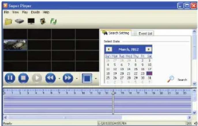
16Appendix B Calculate Recording Capacity
You can calculate the size of hard disk according to the storage time and HD TVI Hybrid DVR recording settings. The formula is as follows in full frame rate condition. Used space per hour (MB/h) = Bitrate (kbps) ÷ 8 × 3600 ÷ 1024. The below are the details at different settings.
| Resolution | Frame Rate | Record Bit Rate (kbps) | Used Space(MB/h) |
| 1080P | 15fps (NTSC)/ 12(PLA) | 12M | 2700 |
| 10M | 2250 | ||
| 8M | 1800 | ||
| 6M | 1350 | ||
| 4M | 900 | ||
| 2M | 450 |
The calculation format is:
Total Recording capacity = Used space per hour (MB/h) (coverage rate of hard disk) × recording time (hour) × channel numbers
For instance, one customer sets resolution to 1080P, frame rate to 15fps, bitrate to 4M and enables total 4 channels. He wants the unit to record continuously for a month. Below is the calculation:
$$ \begin{array}{l} \text { Total Recoding capacity } = 4 5 0 (\mathrm{mb/h}) \times 2 4 (\text { hours / day }) \times 3 0 (\text { days }) \times 4 (\text { channels }) \ = 1 2 9 6 0 0 0 (\mathbf {M B}) \approx 1 2 6 6 (\mathbf {G B}) \end{array} $$
Therefore, customers need to install one SATA HDD with 1.5TB to record for one month.
Detailed Specifications VT-TTR410
| TVI Video Inputs | 4 Channels TVI via BNC (1080P) |
| IP Camera Support | 1 (6 Mbps) |
| Compression | H.264 High profile |
| Recording (720P) | 120fps: 30fps per channel |
| Recording (1080P) | 60fps: 15fps per channel |
| Local Playback | 4 CH |
| OS | Embedded Linux |
| Video Output | VGA x 1CH : 1080P / HDMI x 1CH :1080P |
| Multi Operation | Pentaplex: Live Display / Record / Playback / Backup / Remote Access |
| Local Two-Way Audio | Input: RCA x 1 / Output: RCA x 1 |
| Encode | VBR / CBR |
| Quality Levels | 6 level |
| Recording Modes | Manual, Timer, Motion, Sensor |
| File Management | Lock, Unlock, Reserving time, Redundancy |
| Search | Time, Motion,Sensor,Single or Multi-channel |
| Function | Play, Pause, FF,FB,Shutter Control ,Jog,Digital zoom |
| Alarm Modes | Sensor,Motion,Video loss |
| Alarm Triggering | Record, PTZ move, Relay out,E-mail, etc |
| Network Interface | RJ45 x 1 |
| Remote Viewing | CMS / Web Browser / Mobile (iOS/Android) |
| Remote Playback | 4CH |
| Dual-stream | Individual Network Video Stream and local recording stream, set separately |
| Remote Users | 10 users online, dual stream |
| PTZ Protocol | Pelco D, Pelco P, RANGE, VISCA, DSCP, VIDO, STAR, NEON, MINKING, LILIN |
| Protocol | TCP/IP, UDP, DHCP, DNS, PPPOE, DDNS, SMTP, RTSP, HTTP |
| SATA HDD | Up to 4TB (1 x 4TB) |
| RS485 | RS485 x1 (for PTZ or Keyboard) |
| USB | USB2.0 x 2 (for mouse and USB backup device) |
| Accessory | Remote controller, SATA cable, USB mouse |
| Power Supply | DC: 12V |
| Working Environment | 10°C ~50°C, 10% ~ 90%(Humidity) |
| Dimensions | 10.04" x 1.65" x 8.27" (255mm × 42mm × 210mm) |
| Detailed Specifications VT-TTR820 | |
| TVI Video Inputs | 8 Channels TVI via BNC (1080P) |
| IP Camera Support | 4 (12Mbps) |
| Compression | H.264 High profile |
| Recording (720P) | 240fps: 30fps per channel |
| Recording (1080P) | 120fps: 15fps per channel |
| Local Playback | 8 CH |
| OS | Embedded Linux |
| Video Output | VGA x 1CH : 1080P / HDMI x 1CH :1080P |
| Multi Operation | Pentaplex: Live Display / Record / Playback / Backup / Remote Access |
| Local Two-Way Audio | Input: RCA x 1 / Output: RCA x 1 |
| Encode | VBR / CBR |
| Quality Levels | 6 level |
| Recording Modes | Manual, Timer, Motion, Sensor |
| File Management | Lock, Unlock, Reserving time, Redundancy |
| Search | Time, Motion,Sensor,Single or Multi-channel |
| Function | Play, Pause, FF,FB,Shutter Control ,Jog,Digital zoom |
| Alarm Modes | Sensor,Motion,Video loss |
| Alarm Triggering | Record, PTZ move, Relay out,E-mail, etc |
| Network Interface | RJ45 x 1 |
| Remote Viewing | CMS / Web Browser / Mobile (iOS/Android) |
| Remote Playback | 4CH |
| Dual-stream | Individual Network Video Stream and local recording stream, set separately |
| Remote Users | 10 users online, dual stream |
| PTZ Protocol | Pelco D, Pelco P, RANGE, VISCA, DSCP, VIDO, STAR, NEON, MINKING, LILIN |
| Protocol | TCP/IP, UDP, DHCP, DNS, PPPOE, DDNS, SMTP, RTSP, HTTP |
| SATA HDD | Up to 8TB (2 x 4TB) |
| RS485 | RS485 x1 (for PTZ or Keyboard) |
| USB | USB2.0 x 2 (for mouse and USB backup device) |
| Accessory | Remote controller, SATA cable, USB mouse |
| Power Supply | DC: 12V |
| Working Environment | 10°C ~50°C , 10% ~ 90%(Humidity) |
| Dimensions | 16.93" x 2.17" x 11.81" (430mm × 55mm × 300mm) |
Detailed Specifications VT-TTR1620
| TVI Video Inputs | 16 Channels TVI via BNC (1080P) |
| IP Camera Support | 8 (24Mbps) |
| Compression | H.264 High profile |
| Recording (720P) | 480fps: 30fps per channel |
| Recording (1080P) | 240fps: 15fps per channel |
| Local Playback | 8 CH |
| OS | Embedded Linux |
| Video Output | VGA x 1CH : 1080P / HDMI x 1CH :1080P |
| Multi Operation | Pentaplex: Live Display / Record / Playback / Backup / Remote Access |
| Local Two-Way Audio | Input: RCA x 1 / Output: RCA x 1 |
| Encode | VBR / CBR |
| Quality Levels | 6 level |
| Recording Modes | Manual, Timer, Motion, Sensor |
| File Management | Lock, Unlock, Reserving time, Redundancy |
| Search | Time, Motion,Sensor,Single or Multi-channel |
| Function | Play, Pause, FF,FB,Shutter Control ,Jog,Digital zoom |
| Alarm Modes | Sensor,Motion,Video loss |
| Alarm Triggering | Record, PTZ move, Relay out,E-mail, etc |
| Network Interface | RJ45 x 1 |
| Remote Viewing | CMS / Web Browser / Mobile (iOS/Android) |
| Remote Playback | 4CH |
| Dual-stream | Individual Network Video Stream and local recording stream, set separately |
| Remote Users | 10 users online, dual stream |
| PTZ Protocol | Pelco D, Pelco P, RANGE, VISCA, DSCP, VIDO, STAR, NEON, MINKING, LILIN |
| Protocol | TCP/IP, UDP, DHCP, DNS, PPPOE, DDNS, SMTP, RTSP, HTTP |
| SATA HDD | Up to 8TB (2 x 4TB) |
| RS485 | RS485 x1 (for PTZ or Keyboard) |
| USB | USB2.0 x 2 (for mouse and USB backup device) |
| Accessory | Remote controller, SATA cable, USB mouse |
| Power Supply | DC: 12V |
| Working Environment | 10°C ~50°C, 10% ~ 90%(Humidity) |
| Dimensions | 16.93" x 2.17" x 11.81" (430mm × 55mm × 300mm) |

TRANSCENDENT
CONSIDER THESE OTHER GREAT PRODUCTS FROM


Transcendent HD-TVI Camera Series 2.1 Megapixel Outdoor HD-TVI Cameras with IR LED Illumination
• 1/3" 2.1 Megapixel Progressive Scan CMOS image sensor
• HD-TVI Technology for cable distances of up to 1500' over COAX
- Backwards compatible with Analog Cameras (960H/D1)
• 2.8\~12mm Varifocal & 3.6mm Fixed Iris Lens Options
• Infrared LED's with up to 150' IR Range
• Digital Wide Dynamic Range (D-WDR)
• True Mechanical Day/Night function by ICR
• 3D-DNR Noise Reduction
• IP66 Weather Resistance
• 12VDC Operation
LIMITED PRODUCT WARRANTY
VITEK products carry a three (3) year limited warranty. VITEK warrants to the purchaser that products manufactured by VITEK are free of any rightful claim of infringement or the like, and when used in the manner intended, will be free of defects in materials and workmanship for a period of three (3) years, or as otherwise stated above, from the date of purchase by the end user. This warranty is nontransferable and extends only to the original buyer or end user customer of a VITEK Authorized Reseller.
The product must have been used only for its intended purpose, and not been subjected to damage by misuse, willful or accidental damage, caused by excessive voltage or lightning.
The product must not have been tampered with in any way or the guarantee will be considered null and void.
This guarantee does not affect your statutory rights.
Contact your local VITEK Reseller should servicing become necessary.
VITEK makes no warranty or guarantee whatsoever with respect to products sold or purchased through unauthorized sales channels. Warranty support is available only if product is purchased through a VITEK Authorized Reseller.
- FEATURES:
- Notes
- Table of Contents
- Introduction ....5
- Basic Operation....8
- Wizard Setup....12
- Live View....13
- Add IP Cameras....17
- Record....20
- Playback....25
- Backup 30
- Alarm....31
- P.T.Z....37
- Network Settings....40
- Other Settings....45
- Device Management....48
- Remote Surveillance....52
- Introduction
- Features
- Front Panel Descriptions
- Rear Panel Descriptions
- Connections
- - Video Connections
- ● Audio Connections
- - PTZ Connection
- Basic Operation
- Startup and Shutdown
- By keyboard and mouse:
- Remote Control
- Entering password by remote control
- Controlling Multiple Devices by remote control
- Using a Mouse
- During live:
- In Configuration:
- In Playback:
- In Backup:
- Using Virtual Keyboard
- Common Buttons
- Wizard Setup
- Live View
- Login
- Live View
- Live View Setup
- To set up camera name:
- Sequence View
- Mask View
- To set up mask area:
- To delete mask area:
- Add IP Cameras
- To add IP cameras via LAN:
- To add IP cameras via WAN:
- Record
- Record Settings
- Manual Record
- Schedule/Continuous Recording
- Motion Based Recording
- Sensor Based Recording
- Playback
- Playback
- Playback by Time Search
- Playback by Event Search
- Playback by File Search
- Snap Setting and Playback by Picture Search
- - Manual Snap
- - Auto Snap
- ● Taking Snapshots on Motion Alarm
- ● Taking Snapshots on Sensor Alarm
- Backup
- Backup
- Clip Backup
- Alarm
- Sensor Alarm
- Motion Alarm
- Video Loss Alarm
- Other Alarm
- Alarm Out
- Some models may not support this function.
- To set up alarm out:
- To set up buzzer:
- Manual Alarm
- P.T.Z
- To set up preset:
- To set up cruise:
- To set up track (Pattern):
- Network Settings
- Network
- To set up network:
- Sub Stream
- To set up sub stream:
- To set up Email:
- NAT
- Other Settings
- UPnP settings:
- - Application
- Other Settings
- Basic Configuration
- Advanced Settings
- Device Management
- User Management
- To delete user:
- To modify user:
- To change user password:
- Disk Management
- To format the disk:
- View Information
- Shutdown
- Upgrade
- Remote Surveillance
- IE Remote Surveillance by NAT
- IE Remote Surveillance via LAN & WAN
- Connect the device to internet through router or virtual server.
- Connect the device to internet directly.
- Remote Surveillance through Apple PC
- Connect the DVR to internet directly.
- Remote Live View
- Screen display mode:
- Snap pictures:
- PTZ control
- Remote Playback & Backup
- Remote Playback
- By Time Search:
- By Event Search:
- ▶ File Management:
- Remote Backup
- Remote System Configuration
- Tools
- Remote Management
- Appendix A FAQ
- Q1. Why does the HD TVI Hybrid DVR start abnormally even after connecting the power?
- Q2. There is live image display without menu, why?
- Q3. The HD TVI Hybrid DVR LED turns on, however there is no output. Why?
- Q4. Why are no images displayed on few or all the channels of the HD TVI Hybrid DVR?
- Q5. Why can't I find the HDD?
- Q6. The system cannot record, why?
- Q7. Mouse does not work.
- Q8. ActiveX control cannot be downloaded.
- Q9: HD TVI Hybrid DVR displays "please wait..." all the time.
- Q10: How to input password and numbers in the interface?
- Q11: A hard disk is being identified as a new device however it was being used with another HD TVI Hybrid DVR of same model. Should it be formatted prior to use?
- Q12: What is the minimum configuration required for remote monitoring?
- Q13: How to handle the situation that the codec Control is blocked when downloading in VISTA or Win7 system?
- Q14. How to play backup files?
- 16Appendix B Calculate Recording Capacity
- TRANSCENDENT
- CONSIDER THESE OTHER GREAT PRODUCTS FROM
- Transcendent HD-TVI Camera Series 2.1 Megapixel Outdoor HD-TVI Cameras with IR LED Illumination
- LIMITED PRODUCT WARRANTY
Brand : Vitek
Model : VT-TTR410
Category : Unspecified