
IFP9850-E2 - Interactive whiteboard VIEWSONIC - Free user manual and instructions
Find the device manual for free IFP9850-E2 VIEWSONIC in PDF.


| Product Type | Interactive Whiteboard |
| Brand | Viewsonic |
| Model | IFP9850-E2 |
| Display Size | 98 inches |
| Resolution | 4K UHD (3840 x 2160) |
| Touch Technology | Infrared 20-point touch |
| Brightness | 400 cd/m² |
| Built-in Speakers | 2 x 15W |
| Connectivity | HDMI, VGA, USB, RJ45, RS232 |
| Operating System | Android (embedded) |
| Power Supply | AC 100-240V, 50/60Hz |
| Power Consumption | ≤400W (typical) |
| Weight | Approx. 80 kg (176 lbs) |
| Dimensions (W x H x D) | 2250 x 1350 x 100 mm |
| Cleaning | Use soft dry cloth; avoid solvents |
| Safety | Install on sturdy wall mount |
| Spare Parts & Repairability | Contact Viewsonic support |
| General Information | For commercial/educational use |
Frequently Asked Questions - IFP9850-E2 VIEWSONIC
User questions about IFP9850-E2 VIEWSONIC
0 question about this device. Answer the ones you know or ask your own.
Ask a new question about this device
Download the instructions for your Interactive whiteboard in PDF format for free! Find your manual IFP9850-E2 - VIEWSONIC and take your electronic device back in hand. On this page are published all the documents necessary for the use of your device. IFP9850-E2 by VIEWSONIC.
USER MANUAL IFP9850-E2 VIEWSONIC
IMPORTANT: Please read this User Guide to obtain important information on installing and using your product in a safe manner, as well as registering your product for future service. Warranty information contained in this User Guide will describe your limited coverage from ViewSonic® Corporation, which is also found on our web site at http://www.viewsonic.com in English, or in specific languages using the Regional selection box in the upper right corner of our website. "Antes de operar su equipo lea cu idadosamente las instrucciones en este manual"
Model No. VS17853
P/N: IFP9850-3
Thank you for choosing ViewSonic®
As a world-leading provider of visual solutions, ViewSonic® is dedicated to exceeding the world's expectations for technological evolution, innovation, and simplicity. At ViewSonic®, we believe that our products have the potential to make a positive impact in the world, and we are confident that the ViewSonic® product you have chosen will serve you well.
Once again, thank you for choosing ViewSonic®!
> Safety Precau ons
Please read the following Safety Precau ons before you start using the device.
- Keep this user guide in a safe place for later reference.
- Read all warnings and follow all instructions.
- Do not use the device near water. To reduce the risk of fire or electric shock, do not expose the device to moisture.
- Never remove the rear cover. This display contains high-voltage parts. You may be seriously injured if you touch them.
- Avoid exposing the device to direct sunlight or other sources of sustained heat.
- Do not install near any heat sources such as radiators, heat registers, stoves, or other devices (including amplifiers) that may increase the temperature of the device to dangerous levels.
- Use a soft, dry cloth to clean the external housing. For more information, refer to the "Maintenance" section on page 116.
- When moving the device, be careful not to drop or bump the device on anything.
- Do not place the device on an uneven or unstable surface. The device may fall over resulting in an injury or a malfunction.
- Do not place any heavy objects on the device or connection cables.
- If smoke, an abnormal noise, or a strange odor is present, immediately turn the device off and call your dealer or ViewSonic®. It is dangerous to continue using the device.
- The device is a monitor with an LED backlight intended for general office use.
- Do not attempt to circumvent the safety provisions of the polarized or grounding-type plug. A polarized plug has two blades with one wider than the other. A grounding-type plug has two blades and a third grounding prong. The wide blade and the third prong are provided for your safety. If the plug does not fit into your outlet, obtain an adapter and do not attempt to force the plug into the outlet.
- When connecting to a power outlet, DO NOT remove the grounding prong. Please ensure grounding prongs are NEVER REMOVED.
- Protect the power cord from being treaded upon or pinched, particularly at the plug, and at the point where it emerges from the equipment. Ensure that the power outlet is located near the equipment so that it is easily accessible.
- Only use attachments/accessories specified by the manufacturer. - When a cart is used, use with caution when moving the cart/equipment combination to avoid injury from tipping over.

- Disconnect the power plug from the AC outlet if the device is not being used for a long period of time.
- Place the device in a well-ventilated area. Do not place anything on the device that prevents heat dissipation.

- Refer all servicing to qualified service personnel. Service will be required when the unit has been damaged in any way, such as:
» if the power supply cord or plug is damaged
» if liquid is spilled onto or objects fall in the unit
» if the unit is exposed to moisture
» if the unit does not operate normally or has been dropped
> Contents
Safety Precautions....3
Introduction 10
Package Contents 10
Wall Mount Kit Specifications (VESA)....11
Product Overview....12
Control Panel.... 12
I/O Panel.... 13
Remote Control....14
Using Gestures 17
Select and Deselect an Object (Clicking) 17
Display Menu Options (Right-Clicking) 17
Double-Clicking 17
Moving an Object....18
Erasing Digital Ink....18
Swipe Up for General Settings....18
Making Connections....19
Connecting External Devices 19
VGA Connection 19
HDMI Connection.... 19
RS232 Connection 20
USB, Networking, and Microphone Connections.... 21
Media Player Connection 22
SPDIF Connection 23
Video Output Connection 24
Using Your ViewBoard....25
Powering On/Off your ViewBoard....25
Initial Launch Setup 26
vLauncher - Customizable Welcome Screen....28
Tool Bar 29
ViewBoard On-Screen Display (OSD) Menu 35
General Settings 36
Audio Settings 38
Screen Settings.... 39
Display Settings 40
Adjust Settings 41
Advanced Settings 42
Wireless & Networks 42
Wi-Fi 43
Ethernet 44
Wireless Hotspot 45
BT 46
VPN....47
Share 49
Device....51
Theme 51
Display 51
Wallpaper 52
HDMI Out Encryption Setting 53
Burn-in Protection Interval....54
Storage 54
Sound 54
Personal....55
Security....55
Trusted Credentials....55
Clear Credentials 56
Unknown Sources....56
Language & Input 57
Language 57
Current Keyboard 57
Existing Keyboard 58
Startup and Shutdown 59
Startup Channel....59
Built-in PC Startup Option 59
Standby Mode 60
Black Screen After Startup....61
Close Power Off Reminder 61
Password for Screen Lock....62
Input Setting....63
Input Alias Switch 63
Wake on Active Source 64
Auto Search 64
Channel Auto Switch 64
No Signal Power Off....64
HDMI CEC Settings....64
Other Settings....65
Side Toolbar Channel....65
ECO Mode 65
System 66
Date & Time 66
About Device 68
System Update 68
Advanced....70
Mode....70
APP 71
Password 72
USB Disk Enable....72
Privacy 72
Embedded Applications and Settings....73
Embedded Digital Whiteboard App....73
myViewBoard 73
Floating Bar 73
Toolbar 73
vBoard Lite 75
User Interface: 75
Menu Options: 75
Watercolor Feature 76
ViewBoard Cast 77
Cast Sender from Windows-based Devices, Macbook, and Chrome devices. ..... 78
Cast Sender from Mobile Devices: iOS-based (iPhone, iPad) and Android OS based phone/tablet. 79
Cast Out from a Mobile Device that Supports Annotation 80
Air Class 81

Voter 82

Responder....84

Message 84

Manager....84

Exit 84
Other Default Applications....85
Zoom 85
Join a Meeting 86
Start an Instant Meeting....87
Sweeper 88
Screen Lock 89
Set Password 89
Screen Lock Enabled....89
Chromium....90
Folders....91
RS-232 Protocol....93
Description 93
RS232 Hardware Specification 93
LAN Hardware Specification.... 94
RS232 Communication Setting....94
LAN Communication Setting 94
Command Message Reference....94
Protocol 95
Set-Function Listing....95
Get-Function Listing 101
Remote Control Pass-through Mode 109
Appendix....112
Specifications....112
Display Modes 113
VGA Mode 113
HDMI Mode.... 113
Troubleshooting 114
Maintenance....116
General Precautions.... 116
Cleaning the Screen.... 116
Cleaning the Case 116
Regulatory and Service Information 117
Compliance Information....117
FCC Compliance Statement.... 117
Industry Canada Statement.... 117
CE Conformity for European Countries 117
Declaration of RoHS2 Compliance.... 118
ENERGY STAR statement.... 119
Indian Restriction of Hazardous Substances 119
Product Disposal at End of Product Life 119
Copyright Information....120
Customer Service 121
Limited Warranty 122
Mexico Limited Warranty.... 125
> Introduc on
Package Contents
- HDMI cable • Stylus pen x 2
• Power cable x 4 • Quick start guide - Remote control • RS232 adapter
- AAA battery x 2 • Clamp x 5
- USB cable • Plate
- AV cable • Screw x 8


Wall Mount Kit Speci ca ons (VESA)
NOTE: Please follow the instructions in the wall mount installation guide to install your wall mount or mobile mount bracket. If attaching to other building materials, please contact your nearest dealer.

| Model VESA Spec. (A x B) Standard Screw (C x D) Quan ty | |||
| IFP9850-3 - 98” | 800 x 600 mm M8 x 25 mm 4 | ||
NOTE: Do not use screws that are longer than the standard dimension, as they may cause damage to the inside of the display.
Product Overview
Control Panel

| Number Descrip on | |
| 1 | Areas for placing touching pen |
| 2 | Press the key to turn on the devicePress the key to turn off/on the display backlight only Press and hold the key to turn off the device |
| 3 | Remote control receiver |
| 4 | USB port for Embedded Player and internal PC |
I/O Panel

| Number Descrip on | |
| 1 | Extend content out to another display device |
| 2 | USB port for Embedded Player and internal PC |
| 3 | • Touch signal output to the external PC• Touch 1 for HDMI IN 2 and 3• Touch 2 for HDMI IN 1 and VGA IN |
| 4 | • High-definition multimedia interface signal input, connect to PC with HDMI output, set-top box, or other video device• HDMI 1, 2, 3 support up to 3840x2160@60Hz, HDCP 2.2• HDMI 1, 2, 3 support HDMI CEC(One Touch Play, System Standby, partial Remote Control Pass Through) |
| 5 | External computer image input |
| 6 | External computer audio input |
| 7 | SPDIF output |
| 8 | Serial interface, used for mutual transfer of data between devices |
| 9 | Audio output to the external speaker |
| 10 | Standard RJ45 (10M/100M/1G) Internet connection interface• Used for the Embedded Player and Slot-in PC |
| 11 | Power On / Off switch |
| 12 | AC power input |
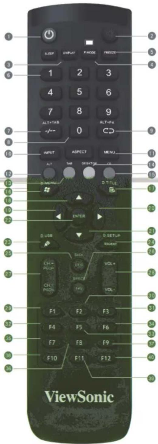
Remote Control
1
Press to turn the display ON/OFF
2
Mute / Unmute
3 DISPLAY :
Display information of the current input source
4 P.MODE :
Blank screen
5 FREEZE:
Freeze screen
6 Numeric button:
Numeric input button
7 -/-、ALT+TAB:
Press to switch between PC applications
8 0:
Numeric input button
9、ALT+F4:
Close current PC window
10 INPUT:
Source selection button
11 MENU:
Press to display Menu
12 RED+ALT:
Screen capture
13 GREEN+TAB:
PC 'Tab' button
14 YELLOW+DESKTOP:
Switch to slot in PC desktop
15 BLUE+BACKSPACE:
PC 'Backspace' button
16 、19 MENU:
PC 'Windows' button
17 、D. TITLE:
PC 'Menu' button
18 ▲ :
Press to scroll up
◀ :
Press to scroll left
20
Press to scroll right
21 ▼ :
Press to scroll down
22 ENTER:
Enter button. Press it to select options.
23 D. USB:
Writing software startup
24 ESC/EXIT、D. SETUP:
Shortcut button to exit dialog boxes
25 EPG:
Back
26 FAV、SPACE:
PC 'Space' button
27 CH. +、CH.-:
CH+ : PC previous page
CH- : PC next page
20 VOL, VOL-
Increase / Decrease volume
29 F1:
Windows F1 Function
30 F2:
Windows F2 Function
31 F3:
Windows F3 Function
32 F4:
Windows F4 Function
33 F5:
Windows F5 Function
34 F6:
Windows F6 Function
35 F7:
Windows F7 Function
36 F8:
Windows F8 Function
37 F9:
Windows F9 Function
38 F10:
Windows F10 Function
39 F11:
Windows F11 Function
40 F12:
Windows F12 Function
Inser ng Remote Control Ba eries
To insert batteries into the remote control:
- Remove the cover on the rear of the remote control.
-
Insert two "AAA" batteries, ensuring the "+" symbol on the battery matches the "+" on the battery post.
-
Replace the cover by aligning it with the slot on the remote control and snapping the latch shut.
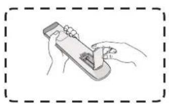
(1)
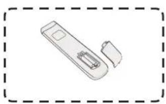
(2)
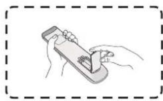
(3)
WARNING: There is a risk of explosion if batteries are replaced with the incorrect type.
NOTE:
- It is recommended that you do not mix battery types.
- Always dispose of old batteries in an environmentally friendly way. Contact your local government for more information on how to dispose of batteries safely.
Remote Control Receiver Range
The working range of the remote control is shown here. It has an effective range of 8 meters. Ensure there is nothing obstructing the remote control's signal to the receiver.

Using Gestures
Touch gestures allow the user to use pre-determined commands without using a keyboard or mouse. Using gestures on the Board, the user can select/deselect objects, change the location of an object, access settings, erase digital ink, and much more.
Select and Deselect an Object (Clicking)
Press and release the viewsboard to select/deselect options or objects. This is like a single, standard left mouse click.

Display Menu Op ons (Right-Clicking)
Press and hold the viewsboard with your finger. This is like a single, standard right mouse click.

Double-Clicking
Quickly press and release twice in the same location on the viewsBoard. This is like a double, standard left mouse click.

Moving an Object
Press and hold the object on the ViewBoard and slowly drag it with your finger to your desired location.
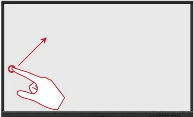
Erasing Digital Ink
Use your flattened hand, palm, or fist on the ViewBoard and move your hand across the area which you wish to erase.

Swipe Up for General Se ngs
Swipe up from the bottom of the ViewBoard to launch the General Settings. To learn more see page 35.

> Making Connec ons
This section guides you on how to connect the ViewBoard with other equipment.
Connec ng External Devices

VGA Connec on
To connect via VGA:
- Connect a VGA cable (15-pin) from your external device to the VGA IN port on the display.
- Connect an audio cable from the AUDIO OUT port on your external device to the AUDIO IN port on the display.
- Connect a USB cable to the external device from the TOUCH OUT port of the display.
HDMI Connec on
To connect via HDMI:
- Connect an HDMI cable from your external device to the HDMI IN port on the display.
- Connect a USB cable to the external device from the TOUCH OUT port of the display.
RS232 Connec on
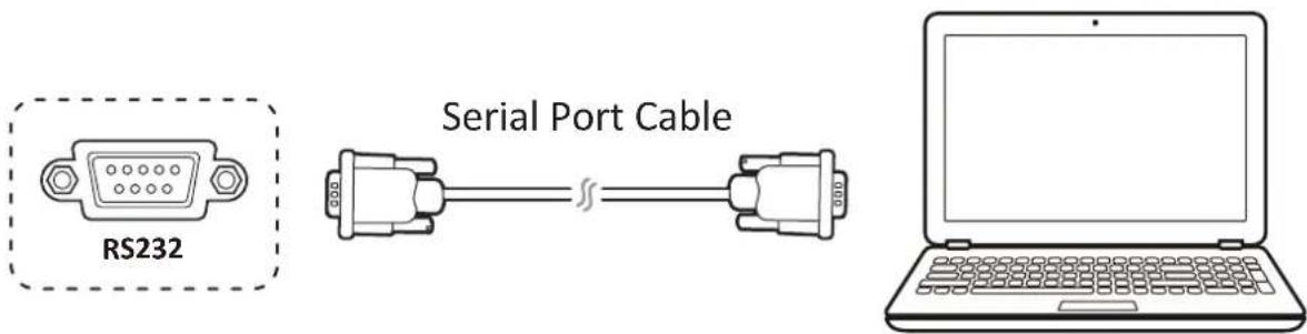
When you use a RS232 serial port cable to connect your display to an external computer certain functions can be controlled remotely by the PC, including Power On/Off, Volume adjustment, Input select, Brightness, and more.
ViewSonic also offers a complimentary software, vController, that allows users to control their ViewSonic commercial displays from a remote PC.
USB, Networking, and Microphone Connec ons
Just like any PC, it is easy to connect various USB devices and other peripherals to your viewsboard.
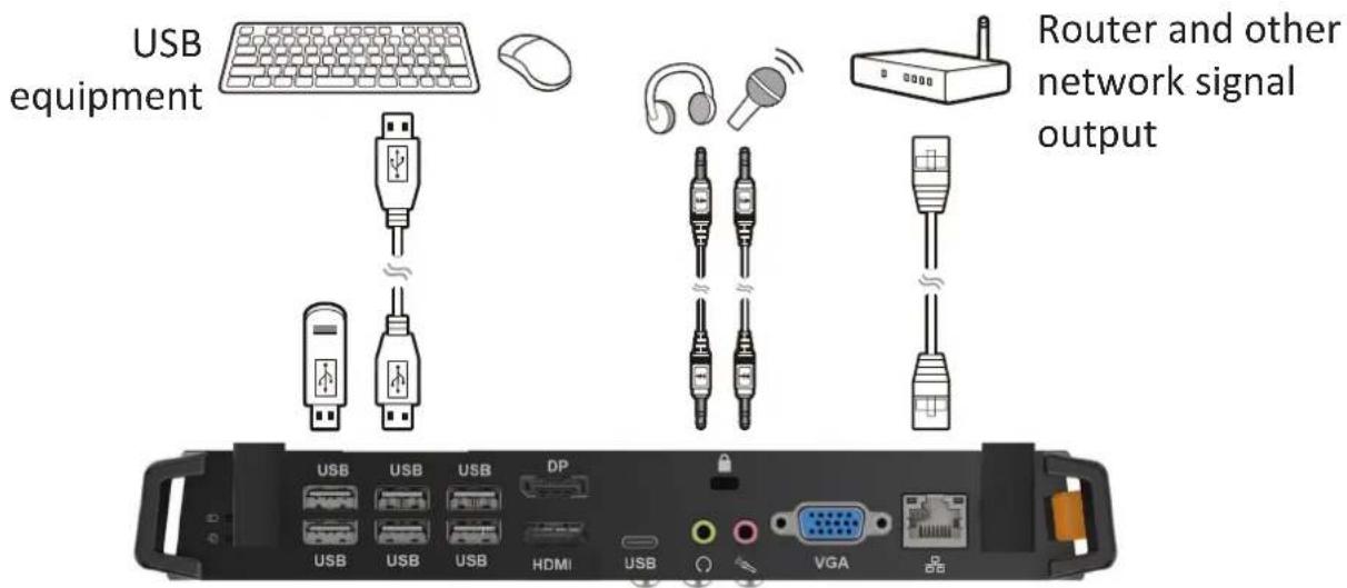
USB Peripherals
Plug the USB device cable into the USB IN port.
Networking and Modem cables
Plug the router cable into the LAN IN port.
Microphone
Plug the microphone cable into the MIC port.
Media Player Connec on

To connect to a media player:
- Connect the HDMI cable to the HDMI ports on your viewsBoard and peripheral device.
- Plug in the power cord of your viewsboard, and turn on the rear-panel power supply switch.
- Press the ⏻ Power button on the right-hand side of the viewsBoard to turn the screen on.
- Press the INPUT button to switch to the "HDMI" input source.
NOTE:
• HDMI 1/2/3 supports up to 3840 x 2160 @ 60Hz
• HDMI 1/2/3 supports HDMI CEC
SPDIF Connec on
![graph TD A["SPDIF"] --> B["SPDIF"] B --> C["Power amplifier/stereo equipment"]](/content/2026/06/1246120/images/9949130da840f774e3712fc43d65ff5ea692c559d3836859085ef3665b48928f.jpg)
To connect to an external sound system:
- Connect an optical cable from DIGITAL OUT to your sound system's optical connector.
- Plug in the power cord of your ViewBoard, and turn on the rear-panel power supply switch.
- Press the ⏻ Power button on the right-hand side of the viewsboard to turn the screen on.
Video Output Connec on
![graph TD A["AV IN"] --> B["Audio cable"] C["AUDIO OUT"] --> B D["HDMI OUT"] --> E["HDMI cable"] F["USB 3.0"] --> E G["HDMI IN 3"] --> H["HDMI cable"] I["Projector"] --> J["HDMI IN"]](/content/2026/06/1246120/images/224e88e216db004d5e4328a2e49fcfbaf867e7eca42df8cc11c38f9d6b64a1ab.jpg)
To output video via a display device:
- Connect an HDMI cable to the HDMI IN port of your display device, and the other end to the HDMI OUT port of your ViewBoard.
- For audio, connect one end of an audio cable to your ViewBoard's AUDIO OUT port and the other end to your speakers.
- Plug in the power cord of your viewsBoard, and turn on the rear-panel power supply switch.
- Press the ⏻ Power button on the right-hand side of the viewsBoard to turn the screen on.
NOTE: The HDMI OUT port can output a resolution of 1920 x 1080 @ 60Hz.
> Using Your ViewBoard
Powering On/O your ViewBoard
- Ensure the power cord is connected, plugged into a power outlet, and the power switch is in the "On" position.

- Press the ⏻ Power button to turn on the viewsBoard.
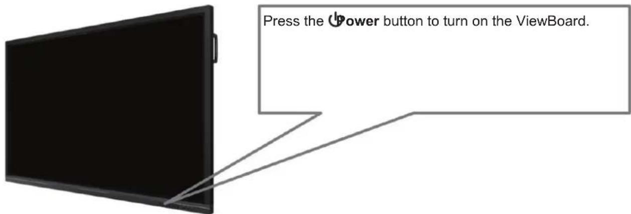
- To turn the viewsboard off, press and hold the ⏻ Power button again.
Ini al Launch Setup
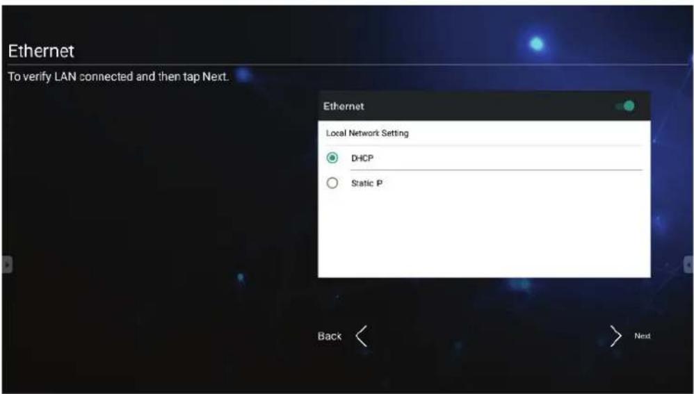
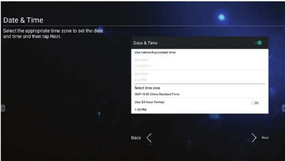
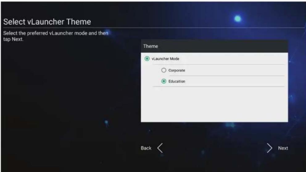
When you first turn on your viewsBoard, an initial setup wizard will launch.
1. Select your Language:

2. Setup and verify your LAN connection:
- Select your Time Zone to set the Date and Time:
- Select your preferred System Mode:

- Select your preferred vLauncher mode:
vLauncher - Customizable Welcome Screen
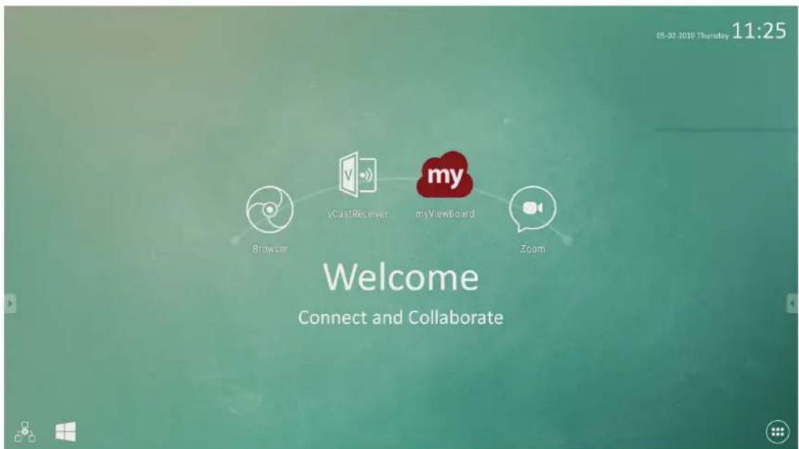
| Icon Descrip on | |
 | Launches the myViewBoard annotation application |
 | Launch wireless screen sharing application, vCastReceiver |
 | Switch to slot-in PC source |
 | Open web browser |
 | Open cloud meeting |
 | Application list |
NOTE: viewsBoard offers two background themes, Corporate and Education.


Tool Bar
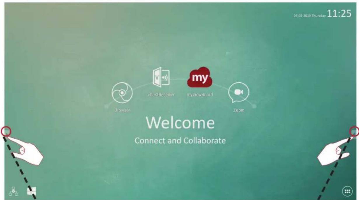
Tool bar trigger icons are on the edge of the ViewBoard 1 launcher providing access to your tools.
To launch a tool:
- Tap a Tool bar trigger icon.
- Tap on your desired tool icon.

NOTE: The default tool bar setting is to be available for all input sources; however, users can go to Advanced Settings to adjust the options: (1) available for all input sources, (2) available for all input sources, except for PC, and (3) disable the tool bar.
| Icon | Descrip on |
 | Return to the previous operation screenNOTE: Only for Embedded Player source |
 | Return to the home screen of the Embedded Player |
 | Display all embedded applications that are being used |
 | Launch the myViewBoard software |
 | Access the pen, highlighter, clear, and save options1 2 3 4 5 6 7 |
| 1. Digital PenAnnotate the overlay of any input source with red, black, blue, or green ink.NOTE: The default digital pen setting supports up to 10-point writing. | |
| 2. Digital HighlighterMark and highlight with four colors: yellow, orange, blue, and green.NOTE: The default digital highlighter setting supports up to 10-point marking. | |
| 3. BrushClears all the digital ink on the screen. | |
| 4. Save AsSave the on-screen image onto the internal storage. | |
| 5. Writing ModeTransparent mode: Screen won't be frozen, the screen resolution won't be reduced to 1080p. | |
| 6. Picture Save SettingSpeed priority: Save the on-screen image as 1920 x 1080; fast save speed.Quality priority: Save the on-screen image as 3840 x 2160; save time will take up to 10 seconds.NOTE: In opaque mode, the user cannot select the picture save setting. | |
| 7. CloseClose the digital pen icon. | |
 | Convert the currently displayed content into a still image; then you can zoom in or zoom out    1 2 3 4NOTE: The ViewBoard will take a few seconds to reduce the screen resolution to 1080p. 1 2 3 4NOTE: The ViewBoard will take a few seconds to reduce the screen resolution to 1080p. |
| 1. Zoom InEnlarge the captured image.NOTE: The screen resolution will be reduced after zooming in. | |
| 2. Zoom OutShrink the captured image. | |
| 3. Back to Full ScreenReset the Zoom In/Zoom Out effects to the original full screen. | |
| 4. CloseClose the icon. | |
 | View more applications within the ViewBoard tool bar     1 2 3 4 5 1 2 3 4 5 |
1. SpotlightHighlight the focus content zone. Tap the Setting icon to adjust the spotlight size and alpha blending effect. 2. CountdownAccess the countdown timer with an optional alarm setting. Touch and swipe to adjust the numeric values, then click Start. 2. CountdownAccess the countdown timer with an optional alarm setting. Touch and swipe to adjust the numeric values, then click Start. At any time, the countdown timer can be paused, resumed, or reset.00:00:4500:00:30PAUSE RESET RESUME RESETThe timer will reduce in size and move to the lower-center of the screen automatically when the user touches another area. Touching the timer again will return it to its normal size and original location.00:00:18 At any time, the countdown timer can be paused, resumed, or reset.00:00:4500:00:30PAUSE RESET RESUME RESETThe timer will reduce in size and move to the lower-center of the screen automatically when the user touches another area. Touching the timer again will return it to its normal size and original location.00:00:18 | |
 | |
 | 3. StopwatchTapping Start will initiate the stopwatch.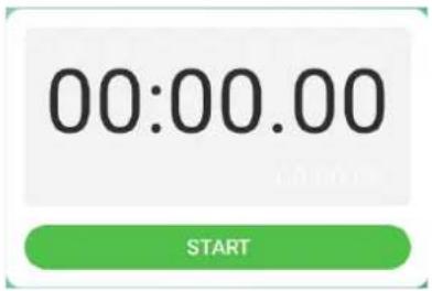 At any time, the stopwatch can be paused, resumed, split, or reset. At any time, the stopwatch can be paused, resumed, split, or reset.  The stopwatch will reduce in size and move to the lower-center of the screen automatically when the user touches another area. Touching the stopwatch again will return it to its normal size and original location.00:00:18 The stopwatch will reduce in size and move to the lower-center of the screen automatically when the user touches another area. Touching the stopwatch again will return it to its normal size and original location.00:00:18 |
| 4. Air ClassInteractive teaching tool for classroom usage. For more information, see page 81. | |
| 5. FolderAccess the Folder function and retrieve documents. For more information, see page 91. |
ViewBoard On-Screen Display (OSD) Menu
ViewBoard has two options for opening the OSD Menu:
Op on 1 Swipe up from the bottom of the screen.

Op on 2
Press the Se ng button on the control panel.

General Se ngs
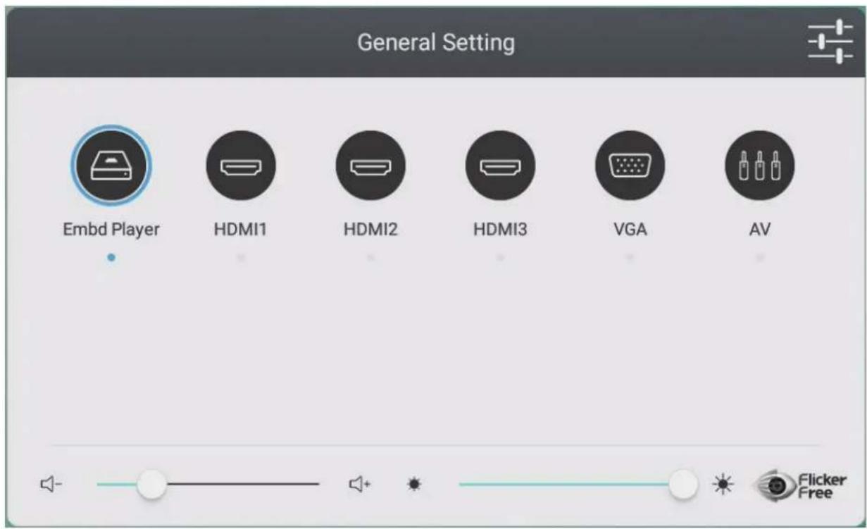
To select an Input Source:
- Press INPUT on the remote control to display the General Setting menu, then press DOWN to enter the Input Source menu.
- Press DOWN/UP/LEFT/RIGHT to select the input source you want.
- Press ENTER on the remote control, or touch the input source.
- Press EXIT on the remote control, or touch a blank area outside of the menu to exit.

To adjust the Backlight and enable/disable Flicker Free:
- Press INPUT on the remote control to display the General Setting menu.
- Drag the brightness slider directly to adjust the backlight value, and/or touch the Flicker Free icon to enable/disable the function.
- Press EXIT on the remote control, or touch a blank area outside of the menu to exit.

To adjust the Volume:
-
Press INPUT on the remote control to display the General Setting menu.
-
Drag the volume slider directly to adjust the value.
-
Press MUTE on the remote control to enable or disable the mute function.
-
Press EXIT on the remote control, or touch a blank area outside of the menu to exit.
Audio Se ngs

- Press MENU on the remote control and select the Audio menu.
- Adjust the Volume, Bass, Treble, and Balance directly by touching and adjusting each value. Additionally, you can use the remote control and press DOWN/UP/LEFT/RIGHT to select a value, then press VOL+/VOL- to adjust it.
- To adjust the audio efficacy choose from: Standard, Mee ng, Class, and Custom.
- Touch the Mute slider directly to enable/disable mute.
Screen Se ngs

- Press MENU on the remote control and select the Screen menu.
- Image S cking Protec on
To reduce the possibility of screen burn-in, this unit is equipped with image sticking protection technology.
If the screen displays a still image for a certain period of time you define, the device activates a screen saver to prevent the formation of burnt in ghost images on the screen.
Image sticking protection moves the picture slightly on the screen. The image sticking protection time setting allows you to program the time between movements of the picture in minutes.
- To change the screen ratio, directly select 4:3, 16:9, or PTP.
Display Se ngs
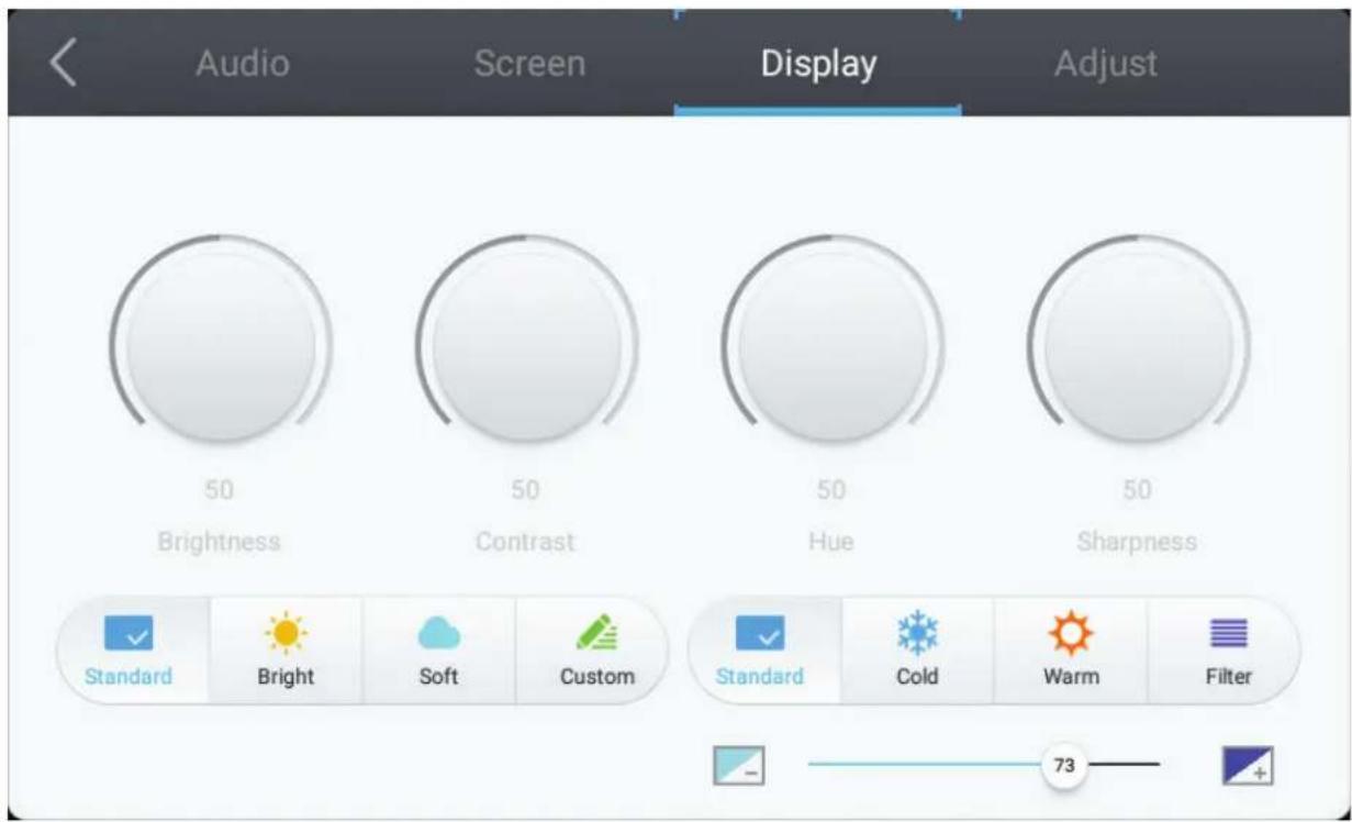
- Press MENU on the remote control and select the Display menu.
- Adjust the Brightness, Contrast, Hue, and Sharpness directly by touching and adjusting each value. Additionally, you can use the remote control and press DOWN/UP/LEFT/RIGHT to select a value, then press VOL+/VOL- to adjust it.
- To adjust the display efficacy choose from: Standard, Bright, So , and Custom.
- Touch the Standard, Cold, or Warm icon to adjust the color temperature.
- Drag the blue light slider directly to adjust the blue light value.
![graph LR A["−"] --> B["73"] C["+"] --> B["73"]](/content/2026/06/1246120/images/6e1acddb4672a74ee3b8739992f1ef3840cc5d172043098a2d5c02206c5d6afa.jpg)
Adjust Se ngs
NOTE: Only available when the input source is VGA.

- Press MENU on the remote control and select the Adjust menu.
- Adjust the H. Position, V. Position, Clock, and Phase directly by touching and adjusting each value.
- To automatically adjust, touch the Auto icon.
Advanced Se ngs
When the viewsBoard is in Embed Player source, tap the Advanced Settings icon in the On-Screen Display (OSD) Menu to enter the Advanced Settings Menu.

Wireless & Networks
Check current network connection status, Wi-Fi, BT, and establish a Wireless hotspot.
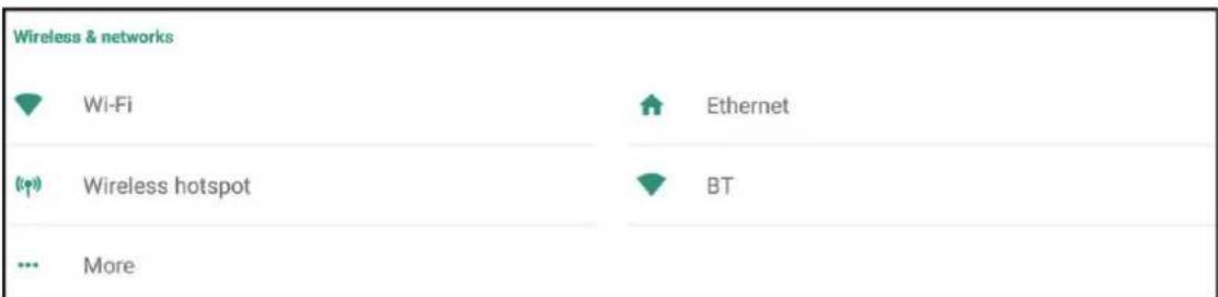
NOTE:
- Wi-Fi, Wireless hotspot and BT settings will appear when LB-WIFI-001(optional) has been installed.
- Ethernet will disable automatically when Wi-Fi is enabled. Wi-Fi will disable automatically when Ethernet is enabled. Wi-Fi will disable when Wireless hotspot is enabled.
- The device cannot connect to the Internet when Wireless hotspot is enabled.
Wi-Fi
Tap the On toggle to toggle Wi-Fi on or off.

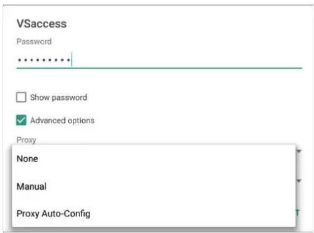
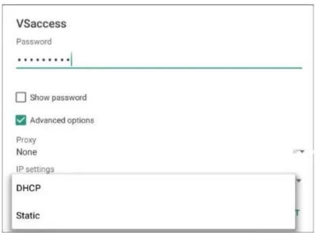
Tap the more settings icon to: Add Network, view Saved Networks, Refresh the network list, or view Advanced settings.

In Advanced settings, you can set Proxy and IP settings.
Ethernet
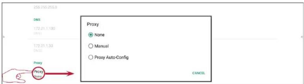
Tap the On toggle to toggle Ethernet on or off.

Tap the more settings icon to view Advanced settings.

In Advanced settings, you can adjust Static IP and Proxy settings.

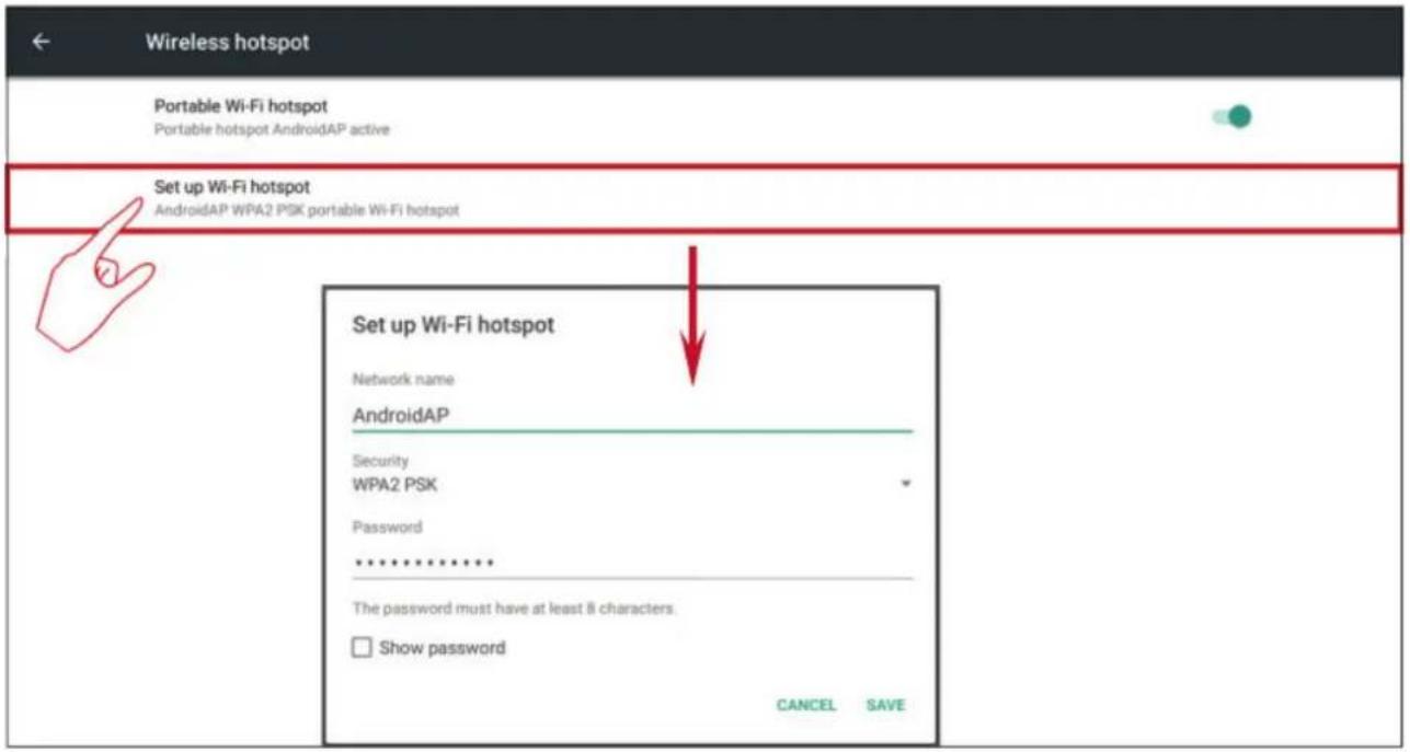
Wireless Hotspot
Tap the Portable Wi-Fi hotspot toggle to turn it on or off.

Tap "Set up Wi-Fi hotspot" to set Network name, Security, and Password.
BT
Tap the On toggle to toggle BT on or off.

Select a listed device to pair and connect.
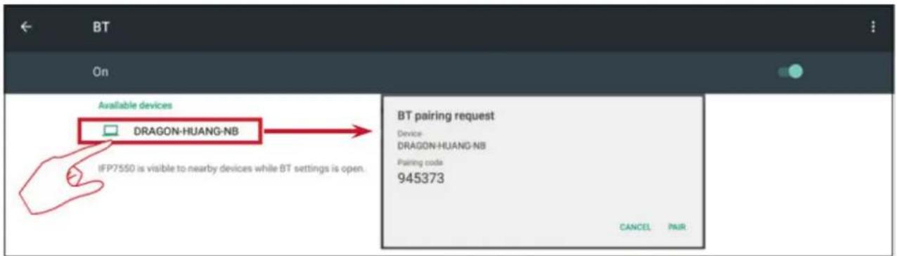
Tap the more settings icon to: Refresh, Rename the device, and Show received files.

VPN
To create a VPN profile:
- Tap the "+" icon.

- Key in the desired name.

3. Select the VPN Type.

4. Choose to enable/disable PPP encryption and show advanced options.

Share
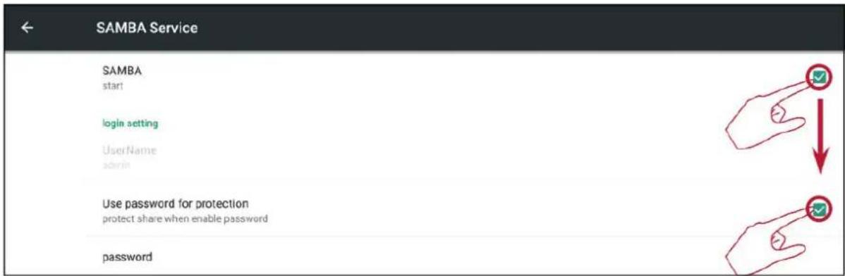
The SAMBA Service provides file sharing via LAN. When the SAMBA Service is enabled, the user can explore the viewsBoard file system with a PC or mobile equipment.

- Tap the box to enable the SAMBA Service, then set a password if needed.
- Connect the ViewBoard and client equipment to the same network.
![Client to ping IFP IFP Ethernet On Static IP IP address 172.18.96.117 Command Prompt Microsoft Windows [Version 10.0.15063] (c) 2017 Microsoft Corporation. All rights reserved. C:\Users\yugang ping 172.18.96.117 Pinging 172.18.96.117 with 32 bytes of data: Reply from 172.18.96.117: bytes=32 time=110…](/content/2026/06/1246120/images/fd80649832d9eff3ff5cddc02ad5185a87d2800618bd300769c2ae6589578b53.jpg)
- Log in to the viewsBoard with the client equipment. Input the viewsBoard's/IFP's IP address.
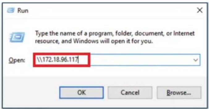
- Key in the user name and password, then select OK.

- After a successful log in, the ViewBoard files will be available.

Device
Adjust the Theme, Display, Storage, and Sound settings.

Theme
Users can change their home launcher theme.

NOTE: vLauncher cannot be removed.
Display
Adjust the Wallpaper, HDMI Out Encryption setting, and Burn-in Protection Interval.
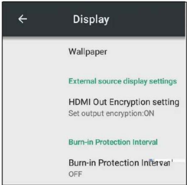
Wallpaper
Users can change their wallpaper with default images, or
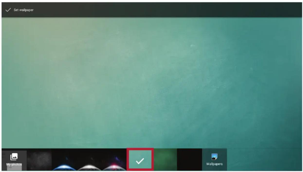
can use their own by tapping My photos and selecting the image file.

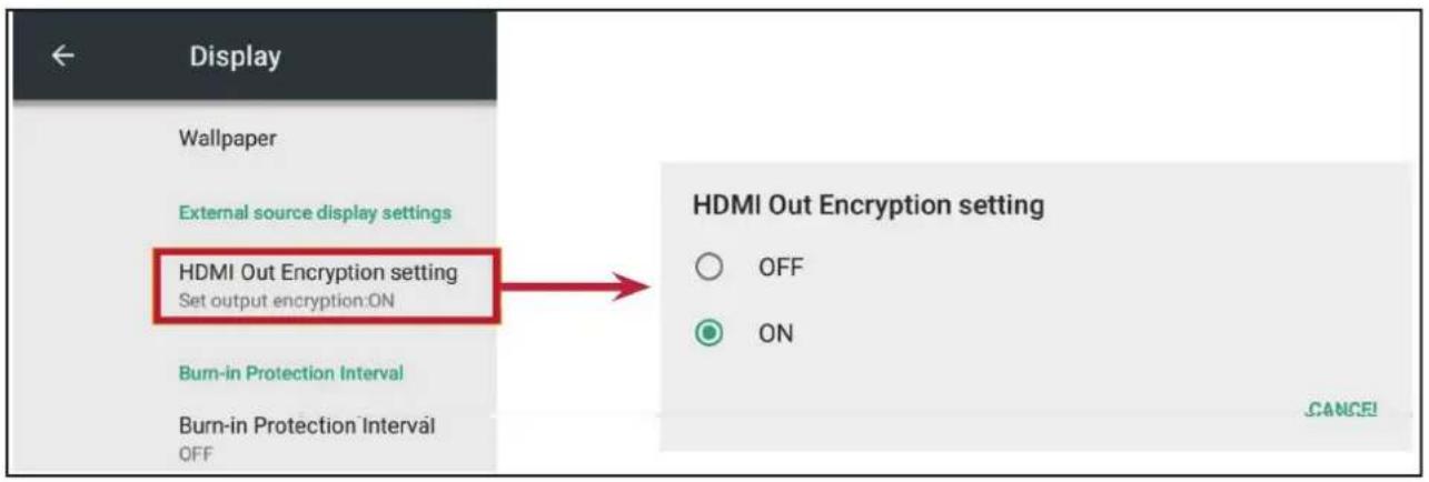
HDMI Out Encryp on Se ng
Users can turn on or off the encryption function.
Burn-in Protec on Interval
This setting allows the user to program the time between movements of the picture in minutes.

NOTE: Burn-in Protection must be enabled in the OSD Menu first.
Storage
Users can check the storage status of their viewsBoard.

Sound
Users can enable or disable touch sounds.

Personal
View and adjust Security, Startup & Shutdown, Language & Input, Password for screen lock, Input, and Other Settings.

Security
Review Credential storage and Unknown sources Install settings.
Trusted Creden als
Show all trusted AC credentials that have been installed on the viewsBoard.

Clear Creden als
Clear any previously installed credentials.

NOTE: Pre-loaded credentials cannot be cleared.
Unknown Sources
Enable the installation of apps from unknown sources.
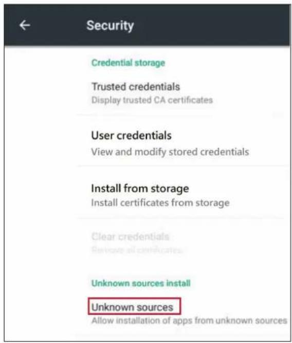
NOTE: Apps from unknown sources may not be compatible.
Language & Input
Adjust the Language and Input method of the Embedded Player.
Language
Choose from the available languages.

Current Keyboard
Enable/disable the visual keyboard or change the default input method.

Exis ng Keyboard
View and adjust advanced entry settings.

Startup and Shutdown
Set the Startup Channel, Standby Mode, Black Screen After Startup, and adjust Timer settings.

Startup Channel
Adjust the startup channel preference.

Built-in PC Startup Op on
Adjust the built-in PC startup preference.
Built-in PC startup option

startup only through PC built-in startup option

startup through any channel
Standby Mode
Decide what happens when you press the Power button while the viewsBoard is On.
Standby Mode

Hibernate

Sleep
Hibernate
When enabled, pressing the Power button will turn off the viewsBoard and the system.
Sleep
When enabled, pressing the Power button will turn off the viewsBoard's backlight, but the system will remain on.
To enable sleep mode:
- The user needs to provide their ViewBoard's serial number (S/N) to ViewSonic. The S/N label is located near the I/O side.
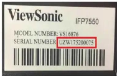
- ViewSonic will then provide the KEY (FakePowerOff) file to the user.

FakePowerOff
- After receiving the KEY file, copy the file to a USB drive.
- Insert the USB drive into the USB port of the viewsBoard.
NOTE: The KEY file MUST match the ViewBoard's S/N.
- Select "Sleep".
NOTE:
- The user does not need to restart the system.
- If the user sets the Standby Mode to Hibernate then to Sleep again, the user needs to repeat steps 3 to 5.
Black Screen A er Startup
When enabled, the viewsBoard will turn off the backlight automatically after the scheduled boot time.

Close Power O Reminder
When enabled, the viewsBoard will turn off the directory without any reminder after the scheduled off time.

To add a schedule:
1. Tap the "+" icon.

2. Adjust the desired times and days. Then tap the to save.

Password for Screen Lock
Set a screen lock password by selecting Set, inputting a password, and selecting OK.

Input Se ng
Enable/disable Input Alias Switch, Wake on Active Source, Channel Auto Switch, Auto Search, and set No Signal Power off.
Input Alias Switch
Once enabled, the user can edit input aliases and when the Display button is pressed the source information (located in the upper left side) will also be changed.

Users can also choose to Display or Hide the input source.

NOTE: Embd Player cannot be hidden.
Wake on Ac ve Source
The viewsBoard will detect HDMI and VGA signals in Standby mode. If HDMI or VGA has a signal output, the viewsBoard will power on automatically.
Auto Search
When enabled, if the current source does not have a signal, the WaveBoard will automatically search the input sources one time.
Channel Auto Switch
When enabled, if the viewsBoard detects a new signal input it will switch the input source automatically.
No Signal Power O
Adjust the "No Signal" power off timer.
HDMI CEC Se ngs
Enable/disable HDMI CEC functions.
| HDMI CEC | |
| Player on then display on(Need to set Standby Mode to Sleep first) | |
| Display off then player off | |
| Player off then display off | |
| Display on then player on | |
| IR pass through |
Other Se ngs
Adjust Side Toolbar Channel and Eco Mode settings.

Side Toolbar Channel
Adjust the side toolbar availability.
ECO Mode
When enabled, the viewsBoard will turn off automatically after sixty (60) minutes of Embedded Player source being idle or after five (5) minutes of other input source without signal.
System
Adjust Date & Time, view About Device, and Advanced Settings.
Date & Time
Set the system time and format.
Automa c Date & Time
When enabled, the viewsBoard will automatically synchronize the date and time via the Internet.
Automatic date & time Use network-provided time

NOTE: Ethernet or Wi-Fi connection is needed.
Set Date
Adjust the values then select OK when finished.

Set Time
Adjust the values then select OK when finished.
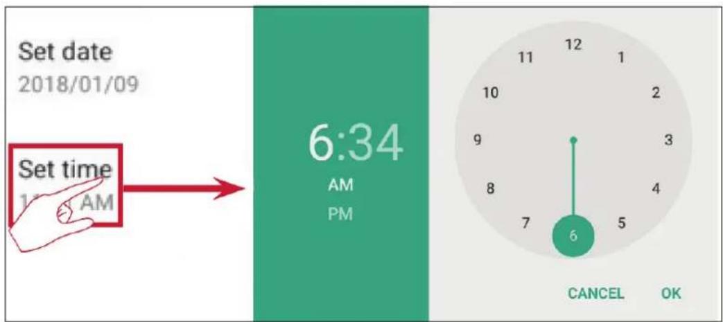
Select Time Zone
Choose from the available time zones.

Select Time Format
Choose from 12 hour and 24 hour time format.

Choose Date Format
Select from the available date formats.

About Device
Display Embedded Player information, System Updates, Display ID Setting, and Asset Tag Setting.
System Update
Upgrade the firmware via OTA.

Legal Informa on
Check open source licenses.
![graph LR A["Legal information"] --> B["Open source licenses"] B --> C["Open source licenses"] C --> D["/kernel\n/system/lib/libbluetooth.a\n/system/lib/libgccdemangle.a\n/system/lib/libgccdemangle.so\n/system/bin/dnsmasq\n/system/bin/ip6tables\n/system/bin/iptables\n/system/lib/libext.a\n/system/lib…](/content/2026/06/1246120/images/bfc1bc1cdc7625e56b672b03f82830393ff2d516b46c93bfffc4e13175467f47.jpg)
Display ID
Change the Display ID.
![graph LR A["Display ID 1"] --> B["Display ID"] B --> C["OK"]](/content/2026/06/1246120/images/d3acdafd0a7c964faa806b7ff8e214d9c4e9638e3bc53e610a2edbba1e3e0d58.jpg)
NOTE: The Display ID is for RS232 users, and the range is 01\~98.
Asset Tag
Key in the asset information.

Advanced
Set the Mode, check Apps, modify Passwords, and enable/disable USB disk connection.
Mode
- Normal Mode: The embedded screen sharing apps will run normally.
• Security Mode: The embedded screen sharing apps will be removed. - Disable Embedded OS: The system will automatically reboot, and then the Embedded OS will not appear.

APP
The user can view app information and force stop, uninstall, move to USB storage, clear data, clear cache, and clear defaults.
NOTE:
- Pre-loaded apps cannot be uninstalled.
- Not all apps support the move to USB storage feature.
• Not all apps support Clear Defaults.

Select the right upper icon for additional options.
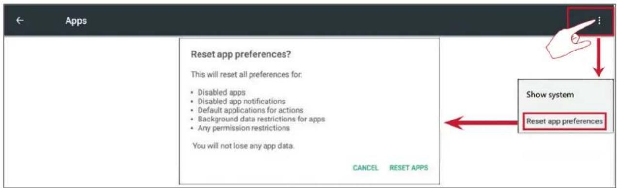
Password
Modify the Advanced setting entry password.
USB Disk Enable
Enable/disable USB disk connection.
Privacy
Set the interval for local file storage access.
» Never: Local storage will be cleaned, and no longer able to save files.
» 1 Hour: Files saved to local storage will be deleted after 1 hour.
» 1 Day: Files saved to local storage will be deleted after 1 day.
» Always: Local storage is available, and no files will be deleted.
Privacy
Set the interval for local storage file access
○ Never
○ 1 Hour
○ 1 Day
Always (Local storage is available, no files will be deleted)
Cancel Confirm
> Embedded Applica ons and Se ngs
Embedded Digital Whiteboard App
Within viewsBoard, ViewSonic offers two versions of the embedded digital whiteboard app, myViewBoard and vBoard Lite, for users to choose from and annotate with.
myViewBoard
Floa ng Bar
 | Move the Floating Bar. | |
| Switch between presentation and preparation modes. | ||
| Paste from the clipboard onto the canvas. | ||
| Click to open the web browser | ||
| Go to the previous canvas. | 1. New myViewBoard File2. Open File3. Save File | |
| Go to the next canvas. | ||
| Add a new canvas. | ||
Toolbar
 | Full Screen Capture | ||
 | Toolbar Move Button | Select and hold to move the toolbar to the left side, right side, or bottom of the screen. | |
 | File Button | ||
| 1. New myViewBoard File2. Open File3. Save File | 4. Save as File5. Export6. Email | ||
 | Import resources (image, video, audio, etc.) to the whiteboard. | ||
 | Infinite Canvas Button | Select – Use two hands to zoom in/out on/of the working panel. | |
 | Selection Button | Select objects, text, and pictures to get other tools. | |
 | Pen Button | Writing tools, changing colors, transparency, thickness, etc. | |
 | Eraser to erase objects or clear the page. | ||
 | Shape/Line Button | Create shapes, select shape colors, insert arrows. |
 | Text Box Creates a Text box. | |
 | Undo Button Undo previous actions. | |
 | Redo Button Redo previous actions. | |
 | Page Toggle Button | Select pages, sort pages, delete pages. |
 | Show or hide the current host information. | |
 | Whiteboard background management menu. | |
vBoard Lite
User Interface:
![graph TD A["Menu"] --> B["Exit"] B --> C["Select"] C --> D["Pen"] C --> E["Eraser"] C --> F["Clean all"] C --> G["Shape"] C --> H["Move / Zooming"] C --> I["Undo"] C --> J["Redo"] C --> K["Add page"] L["Next page"] --> M["Current page"] N["Previous page"] --> O["Previous page"]](/content/2026/06/1246120/images/5ecced5ed31d467bd82a3f8c24701e23e74d08372094f7b987b5a5125fb53871.jpg)
Menu Op ons:
| New |  | New | Click to create new file |
| Open |  | Open | Click to open *.enb format file |
| Save |  | Import | Click to import *.jpg format file |
| Import |  | Save | Click to save current content to *.enb format |
| Export |  | Export | Click to export current content * |
| Background |  | Back-ground | Click to change background |
| Brightness disabled |  | Auto brightness | Click to enable/disable auto brightness |
Watercolor Feature
Additional annotation tool option within vBoard lite.


| Item | Description | |
 | Pen | Click to select different typeNote: In pen mode, it supports up to 10 points for writing |
 | Thickness | Click to change thickness |
 | Palette | Select color then press and rotate the circle on palette to adjust color |
 | Dipper | Click dipper to dip up color for pen |
 | Color disc | Click to change pen color |
ViewBoard Cast
Working with viewsboard® Cast software, the vCastReceiver app, will allow the viewsboard® to receive vCastSender laptop screens (Windows/Mac/Chrome) and mobile (iOS/Android) users' screens, photos, videos, annotations, and camera(s).
![graph TD A["vCastReceiver"] --> B["ViewBoard® Cast"] B --> C["QLFRCU"] C --> D["LAN Port"] D --> E["Connect to the same network (Local Area Network), select 5G mode for optimal casting"] E --> F["6LG6RL"] F --> G["6LG6RL"] G --> H["Connect to in-room wireless access point via Ethernet Cable"] H -->…](/content/2026/06/1246120/images/582e57a6f6f2c341700fe5d7bed088af467552838c07269ea7eb48289128fe15.jpg)
Network Informa on
- ViewBoard® Cast software, laptops, and mobile devices can connect to both the same subnet and across the subnet network.
- Connected devices will show up under "Device List" on the same subnet connection.
- If the device does not show up under "Device List", users will need to key-in the on-screen PIN-code.
ViewBoard Cast is a wireless peer to peer data communication, therefore the below port settings are required:
Ports:
• CP: 56789, 25123, 8121, and 8000
• UDP: 48689 and 25123
Port and DNS ac va on:
- Port: 8001
• DNS: h1.ee-share.com
Cast Sender from Windows-based Devices, Macbook, and Chrome devices.

Mac, Windows, Chrome Devices
- Make sure your device is connected to the same network as the viewsBoard.
- Visit the address that is shown on the viewsBoard to download the application.
- Launch viewsBoard Cast and click the icon number that is shown on the viewsBoard.
Cast Sender from Mobile Devices: iOS-based (iPhone, iPad) and Android OS based phone/tablet.
![graph LR A["Setup"] --> B["1: Make sure your device is connected to the same network with the device."] B --> C["2: Slide up at the bottom enter the quick set Open AirPlay. Or scan the QR-Code to download the client(or input "http://192.168.0.208:8000" in browser)"] C --> D["3: Select the…](/content/2026/06/1246120/images/2d54fb1f73b94945a5f827e14aa4b3b6430c09af4e0abe0e33d4195876563c96.jpg)
Android:
- Make sure your device is connected to the same network as the viewsBoard.
- Enter the password that is shown on the viewsBoard.
- Scan the QR Code that is shown on the viewsBoard to download the client.
- Open the ViewBoard Cast client.
iOS:
- Make sure your device is connected to the same network as the viewsBoard.
- Enter the password that is shown on the viewsBoard.
- Select the device, then the iOS operation interface will appear.
Cast Out from a Mobile Device that Supports Annota on

| Item Description | ||
 | Toggle Click to hide or display tool bar | |
 | Home Click to return to home interface | |
 | Return Click to return to previous operation interface | |
 | Folder Click to view or open mobile device internal file | |
 | Screen sharing | Click to share screen (Android 5.0 above supported) |
 | Touch Click to change to touch mode | |
 | Pen | Click to make annotation in the pictureClick to change color or thickness |
 | Clear Click to clean all the elements | |
 | Camera Click to use camera then send the image to IFP50 | |
Air Class
Display quiz questions on the viewsBoard and allow up to 30 mobile users to submit answers remotely. Whether deploying single or multiple choice questions, the viewsBoard will record the results for each device being used.
![graph TD A["2017 Dec. 20 Wireless"] --> B["LAN Port"] B --> C["Connected to in-room wireless access point via Ethernet Cable"] C --> D["Android phone/tablet: scan QR Code to enter Air Class"] C --> E["Other devices: Connect to the same network (Local Area Network) and enter the URL 192.168.0.161:808…](/content/2026/06/1246120/images/b68329beef68b78de7806804d3cc2898de853a46ccc1b479c9c8fd4599f8fb17.jpg)
Network Informa on
- PC (Windows/Mac/Chromebook) and tablet/mobile (iOS/Android) devices, as well as the ViewBoard need to be linked to the same LAN network subnet.
- Ports: TCP 8080
Select "Enter Air Class" on the viewsboard and select one of the interactive functions to open the Air Class interface.
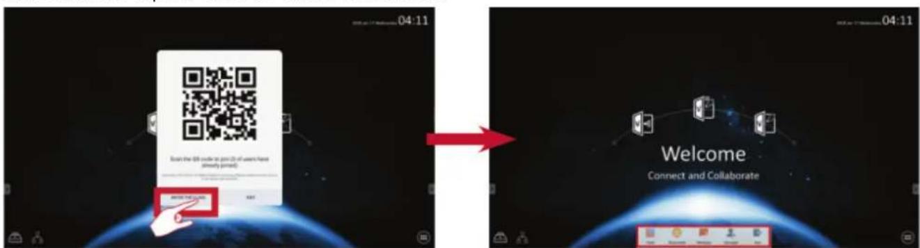


Voter
- Click the Single choice or Mul ple choice icon to select the preferred answer type.

- Click the BEGIN icon to let the participants start.

- After the participants are finished and press the OK icon, the viewsBoard will show the participant's name on screen.

- Click the Finish icon to close the quiz, then the "Answer Statistics" will be displayed.
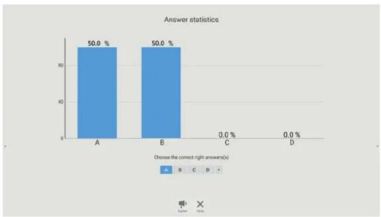
- Choose the right answer to show the correct rate.

- Click the icon to explain and further analyze the topic.


Responder
Participants need to select the OK icon to answer.
![graph LR A["Start"] --> B["FIGHT"] B --> C["OK"] D["Press [OK"] to responder] --> E["START"] F["Press [OK"] to responder] --> G["FIGHT"] H["Apply"] --> I["OK"] J["Be the one"] --> K["RESET"]](/content/2026/06/1246120/images/47f1761bddab0e5e820ba5b5caec69f050da2692701453d97f8dd0dd5f67f98e.jpg)

Message
Click to enable/disable the message function.
![graph LR A["User"] --> B["Responder"] B --> C["Bullet"] C --> D["Manager"] D --> E["Exit"] F["User"] --> G["Responder"] G --> H["Bullet"] H --> I["Manager"] I --> J["Exit"] K["ViewSonic No. 1"] --> L["Response"] L --> M["Bullet"] M --> N["Answer"] N --> O["2018 Jan. 31 Saturday"] O --> P["07:57"]](/content/2026/06/1246120/images/24d896edcd0a353913b6a5cd3bb979ef081e862ef6f9db00fd621e296ae97655.jpg)
Message operation:
- Click the Message icon to enable the function.
- Participants select the Message icon to change the Message interface.
- Participants key in their message then click the Send icon.
- The message will appear at the top of the viewsBoard.

Manager
Select the icon to display a QR Code to let more participants join the class.

Exit
Select to exit the Air Class interface.
Other Default Applica ons
Zoom
Select to launch the Zoom application for video conferencing.
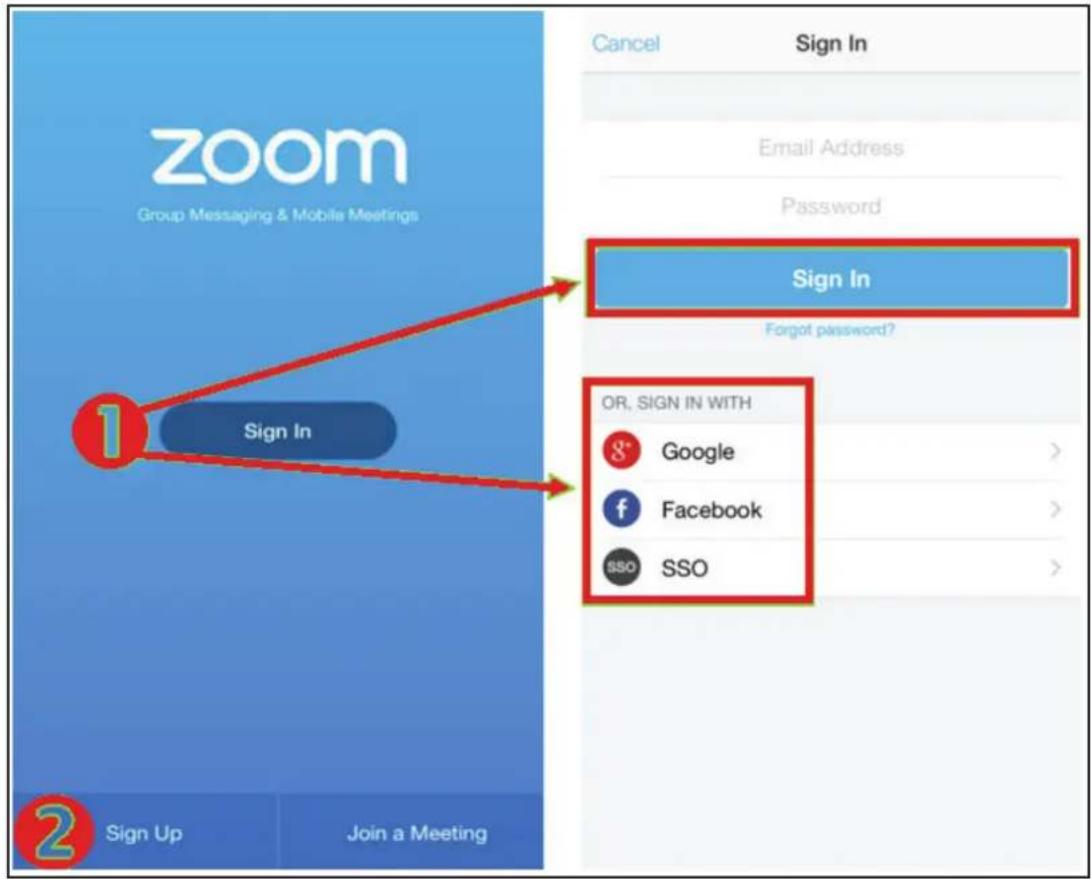
- Select Sign In. Enter your email and password or sign in with your Google, Facebook, or SSO account.
- If you do not have a Zoom account, you will need to select Sign Up.
Join a Mee ng
![graph LR A["Join a Meeting"] --> B["Join with a personal link name"] B --> C["Join Meeting"] D["Jump to chat..."] --> A E["Schedule or Host a Meeting"] --> A](/content/2026/06/1246120/images/52e90ec45f757493674ea4398102104be5af58d13d76a653b73c35194eecbbec.jpg)
- Select Join a Mee ng.
- Enter the Meeting ID of the meeting you want to join.
- Select Join Mee ng.
Start an Instant Mee ng
![graph LR A["Join a Meeting"] --> B["Schedule or Host a Meeting"] B --> C["Video On"] C --> D["Use Personal Meeting ID (PMI)"] D --> E["Upcoming Meetings"] E --> F["Schedule a Meeting"] G["Back"] --> H["My Meetings Refresh"] H --> I["Personal Meeting ID: -311"] I --> J["https://lakehaselwood.zoom.us/…](/content/2026/06/1246120/images/b59778bc516674fe23ece2681de2ce814a970e4d8c563c809ab9dcfd0715d0c3.jpg)
![graph TD A["Invite Others\nInvite your contacts to join this meeting"] --> B["Invite"] A --> C["Mute All"] A --> D["Unmute All"] E["Invite"] --> F["Message"] E --> G["Hangouts"] E --> H["Message+"] E --> I["Email"] E --> J["Gmail"] E --> K["Invite Zoom Contacts"] E --> L["Invite H.323/SIP Room Syste…](/content/2026/06/1246120/images/8eb6cca8ece504cbe76684c7acff7c6be5e2fa807552a98fab3697308b864566.jpg)
- Select Schedule or Host a Mee ng.
- Choose the meeting options:
» Choose to have Video On or Off.
» Choose to Use Personal Meeting ID or a unique meeting ID.
- Select Start a Mee ng.
- Invite meeting participants by selecting Participants at the bottom of the screen.
- Select Invite at the bottom of the Participants screen.
- Choose participants by using the contact method you prefer.
Sweeper
Select the 📄 in to launch the Sweeper application and clear unnecessary data and unwanted files.
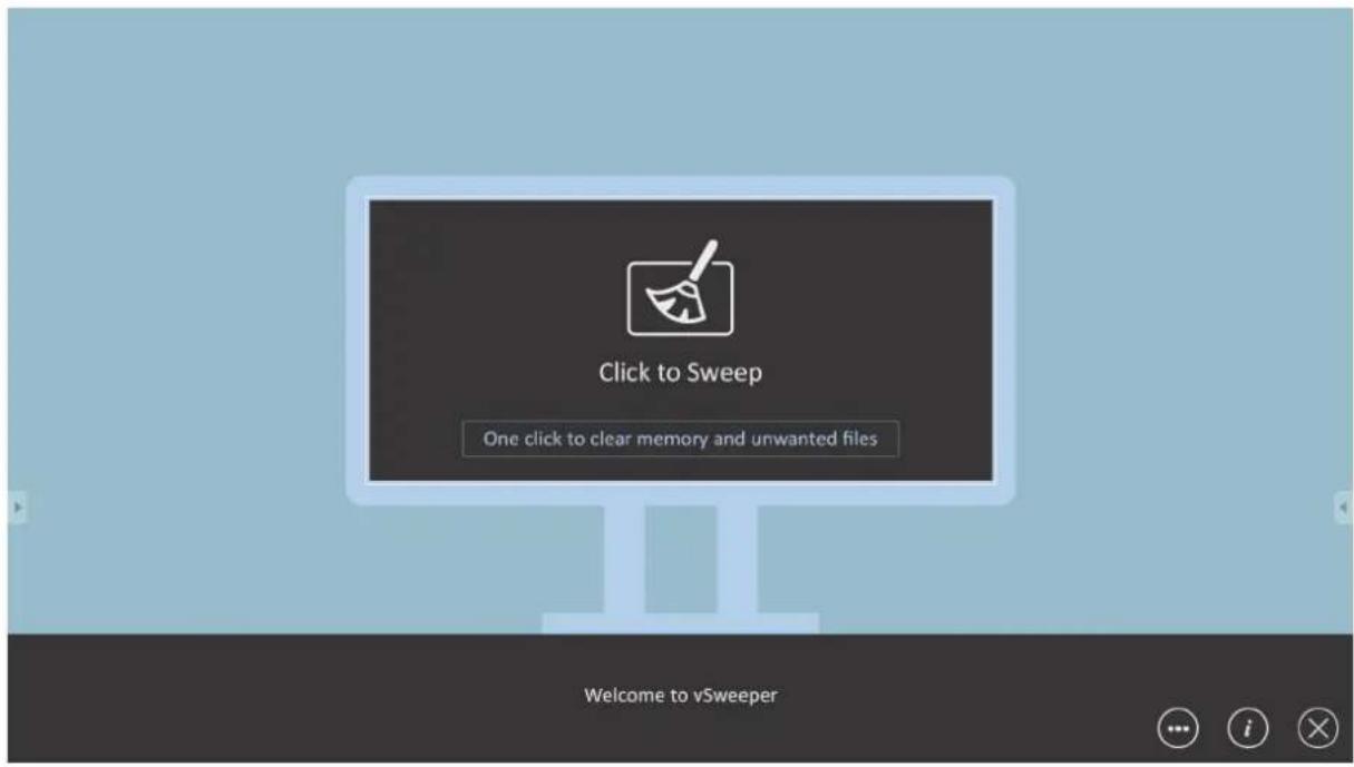
Screen Lock
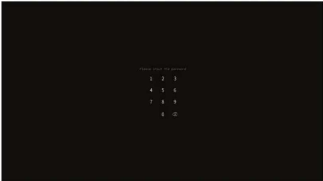
Select the icon to set a screen lock password or enable screen lock.
NOTE: If the user forgets the password, use the remote control and press INPUT 0214 to restore the password to default.
Set Password

Screen Lock Enabled
Chromium
Web browser for surfing the Internet.

Folders
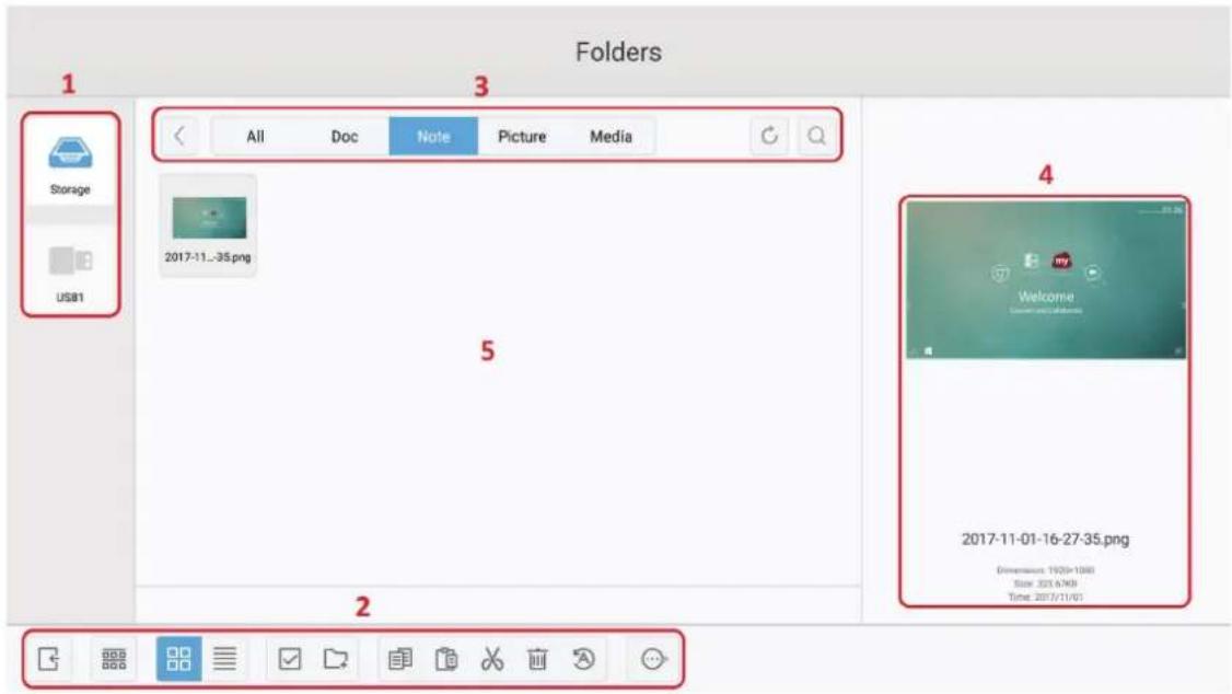
1. Storage Device Display
Select the appropriate storage device.
- Icons
| Item Description | |
| [6KSZ] Exit | Click to exit. |
 Sort Sort | Click to sort file. |
 Thumbnail Thumbnail | Click to display file by thumbnail mode. |
 List List | Click to display file by list mode. |
 Select Select | Click to select file. |
 Add folder Add folder | Click to add folder. |
 Copy Copy | Click to copy file. |
 Paste Paste | Click to paste file. |
 Cut Cut | Click to cut file. |
 Delete Delete | Click to delete file. |
 Rename Rename | Click to rename file. |
 More More | Click to show more functions. |
3. File Type Menu
| Item Description | |
| All | All types |
| Doc OFFICE files | |
| Note | Image stored by vBoard Lite, Side Tool Bar, and remote control Screen Capture button. |
| Picture Image files | |
| Media Audio and | Video files |
4. File Informa on
Preview the image, show the image's name, size, resolution, and creation date.
5. Main Display Area
Display files of corresponding type.
> RS-232 Protocol
This document describes the hardware interface spec and software protocols of RS232 interface communication between ViewSonic LFD and PC or other control units with RS232 protocol.
The protocol contains three command sections:
- Set-Function
- Get-Function
- Remote control pass-through mode
NOTE: Below, "PC" represents all the control units that can send or receive the RS232 protocol command.
Descrip on
RS232 Hardware Speci ca on
ViewSonic LFD communication port on the rear side:
- Connector type: DSUB 9-Pin Male (or 3.5 mm barrel connector)
- Use of crossover (null modem) cable for connection
- Pin Assignment:
Female DSUB 9-Pin

Male DSUB 9-Pin
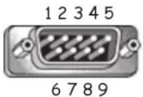
3.5 mm barrel connector (alternative for limited space)

| Pin # Signal Remark | |
| 1 NC | |
| 2 RXD Input to Display | |
| 3 TXD | Output from Display |
| 4 NC | |
| 5 GND | |
| 6 NC | |
| 7 NC | |
| 8 NC | |
| 9 NC Provide +5V/2A power for external specific dongle *3.0 | |
| frame GND | |
| Item | Signal | Remark |
| Tip | TXD | Output from Display |
| Ring | RXD | Input to Display |
| Sleeve | GND |
LAN Hardware Speci ca on
ViewSonic LFD communication port on the rear side:
-
Connector type: 8P8C RJ45
-
Pin Assignment:
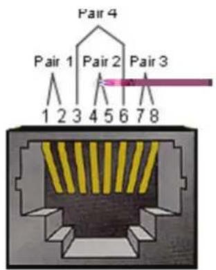
| Pin # Signal Remark | ||
| 1 TX+ Output from Display | ||
| 2 TX- Output from Display | ||
| 3 RX+ Input to Display | ||
| 4 BI_D3+ For 1G case | ||
| 5 BI_D3- For 1G case | ||
| 6 RX- Input to Display | ||
| 7 BI_D4+ | For 1G case | |
| 8 BI_D4- For 1G case | ||
| frame | GND | |
RS232 Communica on Se ng
- Baud Rate Select: 9600bps (fixed)
- Data bits: 8 bits (fixed)
- Parity: None (fixed)
- Stop Bits: 1(fixed)
- Type: Ethernet
- Protocol: TCP/IP
- Port: 5000 (fixed)
- Cross subnet: No
- Logon Credentials: No
Command Message Reference
PC sends to LFD command packet followed by "CR". Every time PC sends control command to Display, the Display shall respond as follows:
- If the message is received correctly it will send “+” (02Bh) followed by “CR” (00Dh)
- If the message is received incorrectly it will send “-” (02Dh) followed by “CR” (00Dh)
Protocol
Set-Func on Lis ng
The PC can control the Display for specific actions. The Set-Function command allows you to control the Display behavior at a remote site through the RS232 port. The Set-Function packet format consists of 9 bytes.
Set-Func on Descrip on:
Length: Total Byte of Message excluding "CR"
LFD ID Identification for each of Display (01\~98; default is 01) ID "99" means to apply the set command for all connected displays. Under such circumstances, only ID#1 display has to reply. The LFD ID can be set via the OSD menu for each Display.
Command Type Identify command type, "s" (0x73h): Set Command "+" (0x2Bh): Valid command Reply "-" (0x2Dh): Invalid command Reply
Command: Function command code: One byte ASCII code.
Value[1\~3]: Three bytes ASCII that defines the value.
CR 0x0D
Set-Func on Format
Send: (Command Type="s")
Reply: (Command Type="+" or "-" )
NOTE: When PC applies command to all displays (ID=99), only the #1 set needs to reply by the name of ID=1.
Example 1: Set Brightness as 76 for Display (#02) and this command is valid. Send (Hex Format)
| Name | Length ID | Command Type | Command Value1 | Value2 | Value3 | CR | |
| Hex | 0x38 0x30 | 0x32 | 0x73 0x24 | 0x30 0x37 0x36 | 0x0D |
Reply (Hex Format)
| Name | Length ID | Command Type | CR | |
| Hex | 0x34 | 0x300x32 | 0x2B | 0x0D |
Example 2: Set Brightness as 75 for Display (#02) and this command is NOT valid Send (Hex Format)
| Name | Length | ID | Command Type | Command | Value1 | Value2 | Value3 | CR |
| Hex 0 | x38 0x30 | 0x32 | 0x73 0x24 | 0x30 | 0x37 | 0x35 0x0 | D |
Reply (Hex Format)
| Name | Length ID | Command Type | CR | |
| Hex | 0x34 | 0x300x32 | 0x2D | 0x0D |
A. Basic Func on
| Set Func on | Length | ID | Command | Command | Value Range | Comments | |
| Type (ASCII) Code(ASCII) | Code(Hex) | (Three ASCIIbytes) | |||||
| Power on/off(standby) | 8 s ! 21 | 000: | STBY | 001: ON | 1. The Power-on via LAN control may works only under specific mode. To see display UG for details. *3.1.12. “WOL by MAC address” may avail-able as alterna-tive.*3.2.1 | ||
| Input Select 8 s “ | 22 000: TV | 001: AV002: S-Video003: YPbPr004: HDMI1014: HDMI2024: HDMI3034: HDMI4005: DVI006: VGA1016: VGA2026: VGA3007: Slot-in PC (OPS/SDM)/HDBT008: Internal memory009: DP00A: Embedded/Main (Android) | 1. No need for USB2. For the case of two more same sources, the 2nd digital is used to indicate the extension.3. The HEX of 00A is 30 30 41. | ||||
| Brightness 8 s | $ | 24 | 000 ~ 100 | 900: Bright down (-1)901: Bright up (+1)*3.1.1 | |||
| Backlight*3.2.0 | 8 | A | B | 42 | 000 ~ 100 | 1. For Android platform whose main mode is controlled by backlight and the other sources are controlled by bright-ness.2. Derived from Color calibration.*3.2.0 | |
| Power lock | 8 | s | 4 | 34 | 000: Unlock001: Lock | *See note in details | |
| Volume | 8 | s | 5 | 35 | 000 ~ 100900: Volume down(-1)901:Volume up(+1) | ||
| Mute | 8 | s | 6 | 36 | 000: OFF001: ON (mute) | ||
| Button lock 8 s | 8 38 000: Unlock | 001: Lock | *See note in details | |||
| Menu lock 8 s > | 3E 000: Unlock | 001: Lock | *See note in details | |||
| Number *3.1.1 8 s | @ 40 000~009 | |||||
| Key Pad *3.1.1 8 s | A 41 000: UP | 001: DOWN002: LEFT003: RIGHT004: ENTER005: INPUT006: MENU/(EXIT)007: EXIT | ||||
| Remote Control | 8 s B 42 000: Disable | 001: Enable002: Pass through | Disable: RCU will be no functionEnabled: RCU controls normallyPass through:Display will bypass the RC code to connected device via the RS232 port, but not react itself. | |||
| Restore default 8 | s ~ 7E | 000 | Recover to factory | setting |
NOTE:
1. Behavior at Lock Modes
| Lock Mode | Behavior |
| Button Lock | 1. Lock all buttons on the front panel and RCU, except for “Power”2. All the SET functions should be workable via RS32, even the ones with according hot key in RCU like Mute,...etc. |
| MENU Lock | 1. Lock “MENU’ key of front panel and RCU2. The Factory and Hospitality modes should not be blocked for the model using MENU-combined key to enter these two modes. Alternative approach will be indicated separately if any limitation by model. |
| POWER Lock | 1. Lock “POWER” key on the front and RCU.2. The SET_POWER on/off should be workable via RS232, but does not mean the POWER lock will be released under this case.3. Can not be unlocked by reset in OSD setting4. Will auto AC power-on in power-lock5. Under power-lock, the set will not enter power saving when no PC signal and neither not turn off when no other video signals after 15 minutes. |
| Remote control disable | Lock the RCU keys, but keep the front panel buttons workable. |
2. Wake-on-LAN by MAC address as alternative for SET Power on
(Length=126 Bytes)
| 6 Bytes | 6 Bytes (#1) | 6 Bytes (#2) | ... | 6 Bytes (#16) | 24 Bytes |
| 0xFF FF ... FF | MAC address | MAC address | ... | MAC address | 0x00 00 ... 00 |
B. Op onal Func on
| Set Func on | Length ID | Command Command Value Range Comments | ||||
| Type (ASCII) Code (ASCII) | Code (Hex) (Three ASCII bytes) | |||||
| Contrast 8 s # | 23 000 ~ 100 | |||||
| Sharpness 8 s | % 25 000 ~ 100 | |||||
| Color 8 s | & 26 000 ~ 100 | |||||
| Tint | 8 s | ‘ 27 000 ~ 100 | ||||
| Backlight On_Off | 8 s | ( 29 000: Off | 001: On | |||
| Color mode | 8 s | ) 29 000: Normal | 001: Warm002: Cold003: Personal | |||
| Surround sound | 8 | s | - | 2D | 000: OFF001: ON | |
| Bass | 8 | s | . | 2E | 000 ~ 100 | |
| Treble | 8 | s | / | 2F | 000 ~ 100 | |
| Balance | 8 s 0 | 30 000 ~ 100 | 050 is central | |||
| Picture Size 8 s | 1 | 31 | 000: FULL (16:9) | 001: NORMAL (4:3)002: REAL (1:1)*3.1.0 | ||
| OSD language | 8 s 2 | 32 | 000: English | 001: French002: Spanish | ||
| PIP-Mode | 8 s 9 | 39 | 000: OFF | 001: PIP(POP)002: PBP | ||
| PIP-Sound select | 8 | s | : | 3A | 000: Main001: Sub | |
| PIP-Position | 8 | s | ; | 3B | 000: Up001: Down002: Left003: Right | |
| PIP-Input | 8 s 7 | 37 | *2.9 | 000: TV001: AV002: S-Video003: YPbPr004: HDMI1014: HDMI2024: HDMI3034: HDMI4005: DVI006: VGA1016: VGA2026: VGA3007: Slot-in PC (OPS/SDM)/HDBT008: Internal memory009: DP00A: Embedded/Main (Android) | ||
| Tiling-Mode 8 s | P 50 000: OFF | 001: ON | (for video wall) | ||||
| Tiling-Compensation | 8 s Q 51 000: OFF | 001: ON | (for video wall)Bezel width compensation | ||||
| Tiling-H by V Monitors | 8 s R 52 01x~09x: H | 0x1~0x9: V | (for video wall)1. 2nd digital for H monitors2. 3rd digital for V monitors | ||||
| Tiling-Position 8 s | S 53 001~025 (for Video wall) | Copy the screen of Position# to identified display | |||||
| Date: Year 8 s | V 56 Y17~Y99 Last 2 digits | (20)17~(20)99 | |||||
| Date: Month 8 s | V 56 M01~M12 2 digits | ||||||
| Date: Day 8 s | V 56 D01~D31 2 digits | ||||||
| Time: Hour | 8 | s | W | 57 | H00~H23 | 24-hr format. 2 digits. | |
| Time: Min 8 s | W | 57 | M00~M59 2 digits | ||||
| Time: Sec | 8 s | W | 57 S00~S59 2 digits | ||||
NOTE:
- Tiling de ni on of H Monitors, V Monitors, and Posi on

- Set Date example
Date: 2017-3/15
Send: 0x 38 30 31 73 56 59 31 37 0D ("Y17")
Send: 0x 38 30 31 73 56 4D 30 33 0D ("M03")
Send: 0x 38 30 31 73 56 44 31 35 0D ("D15")
- Set Time example
Time: 16:27:59
Send: 0x 38 30 31 73 57 48 31 36 0D ("H16")
Send: 0x 38 30 31 73 57 4D 32 37 0D ("M27")
Send: 0x 38 30 31 73 57 53 35 39 0D ("S59")
Get-Func on Lis ng
The PC can interrogate the LFD for specific information. The Get-Function packet format consists of 9 bytes which is similar to the Set-Function packet structure.
Note that the "Value" byte is always = 000.
Get-Func on Descrip on:
Length: Total Byte of Message excluding "CR".
TV/DS ID Identification for each of TV/DS (01\~98; default is 01).
Command Type Identify command type, "g" (0x67h) : Get Command "r" (0x72h) : Valid command Reply "-" (0x2Dh) : Invalid command Reply
Command: Function command code: One byte ASCII code.
Value[1\~3]: Three bytes ASCII that defines the value.
CR 0x0D
Get-Func on Format
Send: (Command Type="g")
Reply: (Command Type="r" or "-"
If the Command is valid, Command Type = "r"
If the Command is NOT valid, Command Type = “-”
Example 1: Get Brightness from TV-05 and this command is valid. The Brightness value is 67.
Send (Hex Format)
| Name | Length | ID | Command | Type | Command | Value1 | Value2 | Value3 | CR | |
| Hex | 0x38 | 0x30 | 0x35 | 0x67 | 0x62 | 0x30 | 0x30 | 0x30 | 0x0D | |
Reply (Hex Format)
| Name | Length | ID | Command | Type | Command | Value1 | Value2 | Value3 | CR | |
| Hex | 0x38 | 0x30 | 0x35 | 0x72 | 0x62 | 0x30 | 0x36 | 0x37 | ||
| 0x0D | ||||||||||
Example 2: Get Color from Display (#05), but the Color command is not supported by this model.
Send (Hex Format)
| Name | Length | ID | Command Type | Command | Value1 | Value2 | Value3 | CR | |
| Hex 0x38 | 0x38 | 0x35 | 30 | 0x67 0x26 | 0x30 | 0x30 | 0x30 0x0D | ||
Reply (Hex Format)
| Name | Length | ID Command Type | CR | |
| Hex | 0x34 | 0x300x35 | 0x2D | 0x0D |
Get-Func on Table
A. Basic Func on
| Get Func on | Length | ID | Command | Command | Response | Range | Comments |
| Type (ASCII) | Code(ASCII) | Code(Hex) | (Three ASCIIbytes) | ||||
| Get-Brightness 8 | g b 62 000 | ~ 100 | |||||
| Get-Backlight*3.2.0 | 8 a B | 42 000 | ~ 100 | 1. For Android | platform whose main mode is controlled by backlight and the other sources are controlled by brightness.2. Derived from Color calibration.*3.2.0 | ||
| Get-Volume 8 g | f | 66 000 ~ | 100 | ||||
| Get-Mute | 8 g g | 67 | 000: Off | 001: On (muted) | |||
| Get-Input select | 8 | g | j | 6A | 000~100~ | 1. 1st digit for signal detection: 0 means "no signal"; 1 means "signal detected"2. 2nd &3rd digit: See Set-function table | |
| Get-Power status:ON/ STBY | 8 g | I 6C | 001: ON | 000: STBY | |||
| Get-Remote control | S | g | n | 6E | 000: Disable001: Enable002: Pass through | Get RCU mode status | |
| Get-Power lock | 8 g o | 6F | 000: Unlock | 001: Lock | |||
| Get-Button lock | 8 g p | 70 000: Unlock | 001: Lock | ||||
| Get-Menu lock | 8 g | I 6C | 000: Unlock | 001: Lock | |||
| Get-ACK | 8 | g | z | 7A | 000 | This command is used to test the communication link | |
| Get-Thermal | 8 g 0 | 30 | 000~100: | 0~+100 deg C-01~-99:-1~-99 deg C | |||
| Get-Operation time*3.2.0 | 8 g 1 | 31 | 000 | 1. Accumulated | hours in 6-digit integer (000,001~999,999)*3.2.02. Can not be reset when FW update and Factory initiation*3.2.23. Reply in new 32-byte format*3.2.0 | ||
| Get-Device name | 8 | g | 4 | 34 | 000 | Reply in new 32-byte format *3.2.0 |
| Get-MAC address | 8 g 5 35 000 | (for the model with | LAN) Reply in new 32-byte format*3.2.0 | |||
| Get-IP address *3.2.0 | 8 g 6 36 000 | (for the model with | LAN) Reply in new 32-byte format*3.2.0 | |||
| Get-Serial number *3.2.0 | 8 g 7 37 000 | Reply in new 32-byte | format *3.2.0 | |||
| Get-FW version *3.2.0 | 8 g 8 38 000 | Reply in new 32-byte | format *3.2.0 |
NOTE:
1. Get Opera on Hour example
Assumed the accumulated operation hour is 123,456 hrs
Send: 0x 38 30 31 67 31 30 30 30 0D (Get Operation hour)
Reply: 0x 32 30 31 72 31 31 32 33 34 35 36 00 00 ... 00 00 0D
2. Get Device Name example
Assumed the device name is CDE-5500
Send: 0x 38 30 31 67 34 30 30 30 0D (Get Device Name)
Reply: 0x 32 30 31 72 34 43 44 45 2D 35 35 30 30 00 00 ... 00 00 0D
Assumed the device name is "NMP-302#1"
Send: 0x 38 30 31 67 34 30 30 30 0D (Get Device Name)
Reply: 0x 32 30 31 72 34 4E 4D 50 2D 33 30 32 23 31 00 00 ...00 00 0D
3. Get MAC address example
Assumed the MAC address is 00:11:22:aa:bb:cc
Send: 0x 38 30 31 67 35 30 30 30 0D (Get MAC add)
Reply: 0x 32 30 31 72 35 30 30 31 31 32 32 61 61 62 62 63 63 00 00...00 00 0D
4. Get IP address example
Assumed the IP address is 192.168.100.2
Send: 0x 38 30 31 67 36 30 30 30 0D (Get IP address)
Reply: 0x 32 30 31 72 36 31 39 32 2E 31 36 38 2E 31 30 30 2E 32 00 00...00 00 0D
5. Get Serial number example
Assumed the Serial number is ABC180212345
Send: 0x 38 30 31 67 37 30 30 30 0D (Get Serial number)
Reply: 0x 32 30 31 72 37 41 42 43 31 38 30 32 31 32 33 34 35 00 00...00 00 0D
6. Get FW version example
Assumed the FW version is 3.02.001
Send: 0x 38 30 31 67 38 30 30 30 0D (Get FW version)
Reply: 0x 32 30 31 72 38 33 2E 30 32 2E 30 30 31 00 00...00 00 0D
B. Op onal Func on
| Get Func on | Length | ID | Command | Command | Response | Range | Comments |
| Type (ASCII) | Code (ASCII) | Code (Hex) | (Three ASCII bytes) | ||||
| Get-Contrast 8 g | a 61 000 ~ | 100 | |||||
| Get-Sharpness 8 g | c 63 000 ~ | 100 | |||||
| Get-Color 8 g | d 64 000 ~ | 100 | |||||
| Get-Tint 8 g | e 65 000 ~ | 100 | |||||
| Get-Backlight On_Off | 8 g h | 68 000: Off | 001: On | ||||
| Get-PIP mode | 8 | g | t | 74 | 000: OFF001: PIP (POP)002: PBP | ||
| Get-PIP input | 8 | g | u | 75 | 000~ | See Set-input select | |
| Get-Tiling Mode | 8 g v | 76 | 000: OFF | 001: ON | (for Video wall) | ||
| Get-Tiling Compensation | 8 g | w | 77 | 000: OFF | 001: ON | (for Video wall)Bezel width compensation | |
| Get-Tiling H by V monitors | 8 g x | 78 01x~09x: H monitors | 0x1~0x9: V monitors | (for Video wall)1. 2nd digital for H monitors2. 3rd digital for V monitors | |||
| Get-Tiling position | 8 g y | 79 | 000: OFF | 001~025 | (for Video wall)Copy the screen of Position# to identified display | ||
| Get-Date: Year | 8 | g | 2 | 32 | Y00~Y00 | Last 2 digits(20)17~(20)99 | |
| Get-Date: Month | 8 g 2 | 32 M00~M00 2 digits | |||||
| Get-Date: Day | 8 g 2 | 32 | D00~M00 2 digits | ||||
| Get-Time: Hour | 8 | g | 3 | 33 | H00~H00 | 24-hr format. 2 digits | |
| Get-Time: Min | 8 g 3 | 33 M00~M00 2 digits | |||||
| Get-Time: Sec | 8 g 3 | 33 | S00~S00 2 digits |
NOTE:
1. Get Date example
Assumed the current date of display#01 as below:
Date: 2017-3/15
Send: 0x 38 30 31 67 32 59 30 30 0D (Get Date:Year)
Reply: 0x 38 30 31 72 32 59 31 37 0D ("Y17")
Send: 0x 38 30 31 67 32 4D 30 30 0D (Get Date:Month)
Reply: 0x 38 30 31 72 32 4D 30 33 0D ("M03")
Send: 0x 38 30 31 67 32 44 30 30 0D (Get Date:Day)
Reply: 0x 38 30 31 72 32 44 31 35 0D ("D15")
2. Get Time example
Assumed the current time of display#01 as below:
Time: 16:27:59
Send: 0x 38 30 31 67 33 48 30 30 0D (Get Time:Hour)
Reply: 0x 38 30 31 72 33 48 31 36 0D ("H16")
Send: 0x 38 30 31 67 33 4D 30 30 0D (Get Time:Min)
Reply: 0x 38 30 31 72 33 4D 32 37 0D ("M27")
Send: 0x 38 30 31 67 33 53 30 30 0D (Get Time:Sec)
Reply: 0x 38 30 31 72 33 53 35 39 0D ("S59")
3. Get RS232 Version example
Assumed the version is 3.0.1
Send: 0x 38 30 31 67 36 30 30 30 0D (Get RS232 version)
Reply: 0x 38 30 31 72 36 33 30 31 0D ("301")
C. Auto Reply *3.2.1
The display will send out the updated data/status automatically without getting a query from the host whenever the following data/status is changed by the user through any of the available ways like: remote control unit, front keys, or touch screen.
- PowerOn/Off
- InputSelect
- Brightness
- Backlight
• Volume - MuteOn/Off
Remote Control Pass-through Mode
When the PC sets the Display to Remote Control Pass through mode, the Display shall send a 7-byte packet (followed by “CR”) in response to remote control unit (RCU) button activation. In this mode the remote control shall have no effect on the Display function. For example: “Volume+” will not change the volume of the Display, but instead only sends the “Volume+” code to the PC over the RS232 port.
IR Pass Through-Func on format
Reply: (Command Type="p")
Example 1: Remote Control Pass-through when “VOL+” key is pressed for Display (#5)
Send (Hex Format)
| Name | Length | ID | Command Type RCU Code1(MSB) | RCU Code2(LSB) | CR | |
| Hex | 0x36 0x30 | 0x35 | 0x70 | 0x31 | 0x30 | 0x0D |
| Key | Code (HEX) | Basic *3.1.1 | Op onal *3.1.1 |
| 1 | 01 | V | |
| 2 | 02 | V | |
| 3 | 03 | V | |
| 4 | 04 | V | |
| 5 | 05 | V | |
| 6 | 06 | V | |
| 7 | 07 | V | |
| 8 | 08 | V | |
| 9 | 09 | V | |
| 0 | 0A | V | |
| - | 0B | V | |
| RECALL (LAST) | 0C | V | |
| INFO (DISPLAY) | 0D | V | |
| 0E | |||
| ASPECT (ZOOM, SIZE) | 0F | V | |
| VOLUME UP (+) | 10 | V | |
| VOLUME DOWN (-) 11 V | |||
| MUTE 12 V | |||
| CHANNEL/PAGE UP (+)/BRIGHTNESS+ | 13 | V | |
| CHANNEL/PAGE DOWN (-)/BRIGHTNESS- | 14 | V | |
| POWER 15 V | |||
| SOURCES (INPUTS) 16 V | |||
| 17 | |||
| 18 | |||
| SLEEP 19 V | |||
| MENU 1A V | |||
| UP 1B V | |||
| DOWN 1C V | |||
| LEFT (-) 1D V | |||
| RIGHT (+) 1E V | |||
| OK (ENTER, SET) 1F V | |||
| EXIT | 20 V | ||
| 21 | |||
| 22 | |||
| 23 | |||
| 24 | |||
| 25 | |||
| 26 | |||
| 27 | |||
| 28 | |||
| 29 | |||
| 2A | |||
| 2B | |||
| RED (F1) | 2C | ||
| GREEN (F2) | 2D | ||
| YELLOW (F3) | 2E | ||
| BLUE (F4) | 2F |
NOTE:
- This IR-pass-through code is different from the RCU key code.
- Special control sequence for POWER key under IR-pass through mode.
2-1. When Display is OFF and receives the IR POWER code: Display will turn itself on, then forward the POWER code to the host via RS232.
2-2. When Display is ON and receives the IR POWER code: Display will forward the POWER code to the host via RS232, then turn off itself.
2-3. When SET-POWER LOCK is enabled, the Display will not respond to POWER key pressing.
3. The VOLUME UP and VOLUME DOWN code will repeatedly output when you press and hold the keys.
> Appendix
Speci ca ons
| Item Category | Speci ca ons | |
| Model IFP9850-3 | ||
| Screen Size 97.52" | ||
| Input Signal 3 x HDMI | 1 x VGA1 x PC audio | |
| Output Signal 1 x HDMI | 1 x Earphone1 x SPDIF | |
| Speaker Output 12W x 2 | ||
| RS232 RS232 | Communication | |
| Power Voltage 100V-240V AC 50/60Hz | ||
| Operating Conditions | Temperature 32°F to 104°F (0°C to 40°C) | |
| Humidity 20%~80% non-condensing | ||
| Altitude | ≤ 2,000 m | |
| Storage Conditions | Temperature | -4°F to 140°F (-20°C to 60°C) |
| Humidity 10%~90% non-condensing | ||
| Altitude | ≤ 2,000 m | |
| Dimensions | Physical (mm) 22 | 45 x 1323 x 91 |
| Weight | Physical (kg) | 101.5 |
| Power Consumption | On | 171W |
| Off | <0.5W | |
NOTE: Product specifications are subject to change without notice.
Display Modes
VGA Mode
| Resolu on Refresh Rate (@) | |
| 640 x 480 60Hz, 72Hz, 75Hz | |
| 720 x 400 70Hz | |
| 800 x 600 56Hz, 60Hz, 72Hz, 75Hz | |
| 1024 x 768 60Hz, 70Hz, 75Hz | |
| 1152 x 864 60Hz, 75Hz | |
| 1152 x 870 75Hz | |
| 1280 x 768 60Hz, 75Hz | |
| 1280 x 960 60Hz | |
| 1280 x 1024 60Hz, 75Hz | |
| 1360 x 768 60Hz | |
| 1366 x 768 60Hz | |
| 1440 x 900 60Hz, 75Hz | |
| 1600 x 1200 60Hz | |
| 1680 x 1050 60Hz | |
| 1920 x 1080 60Hz | |
| 1920 x 1200 60Hz | |
HDMI Mode
| Resolu on Refresh Rate (@) | |
| 640 x 480 60Hz, 72Hz | |
| 720 x 400 70Hz | |
| 800 x 600 60Hz, 72Hz | |
| 1024x768 60Hz, 70Hz, 75Hz | |
| 1280x800 60Hz | |
| 1280x1024 | 60Hz |
| 1360x768 60Hz | |
| 1440x900 60Hz | |
| 1680x1050 | 60Hz |
| 1920x1080 | 60Hz |
| 3840x2160 | 30Hz, 60Hz |
| 480i | 60Hz |
| 480p | 59Hz, 60Hz |
| 576i | 50Hz |
| 720p | 50Hz, 60Hz |
| 576p | 50Hz |
| 1080i | 50Hz, 60Hz |
| 1080p | 50Hz, 60Hz |
Troubleshoo ng
This section describes some common problems that you may experience when using the viewsboard.
| Problem or Issue Possible Solu ons | |
| Remote Control is not working | 1. Check whether something is obstructing the display's remote control receiver.2. Check whether the batteries in the remote control are installed correctly.3. Check whether the batteries need to be replaced. |
| The unit turns off unexpectedly | 1. Check whether Sleep mode is enabled.2. Check if there is a power outage in your area.3. Turn on the display and see if the problem is with the signal and control system. |
PC Mode
| Problem or Issue Possible Solu ons | |
| No PC signal 1. Check the display settings.2. Check the display resolution.3. Adjust the Hs &Vs (synchronization) settings using the OSD menu. | |
| Background streaking 1. Choose auto adjust.2. Adjust clock and phase. | |
| False color 1. Check the VGA connection.2. Adjust the chroma, brightness, and contrast settings. | |
| Unsupported format 1. Choose auto adjust.2. Adjust clock and phase settings. |
Touch Func on
| Problem or Issue Possible Solu ons | |
| Touch function does not work | 1. Check that drivers are installed correctly.2. Reinstall driver(s).3. Check setup and align it.4. Check whether the touch pen is working properly. |
Video Not Working Properly
| Problem or Issue Possible Solu ons | |
| No picture/ No sound 1. | Check the Power status.2. Check the signal cable.3. Check that the internal PC is installed correctly. |
| Picture is unclear or cuts in and out | 1. Check the signal cable.2. Check if other electronics are interrupting the signal. |
| Poor picture 1. Adjust ch | roma, brightness, and contrast settings in the menu.2. Check the signal cable. |
Audio Not Working Properly
| Problem or Issue Possible Solu ons | |
| No sound 1. Press the M | Mute/Unmute button.2. Adjust the volume.3. Check the audio cable. |
| One speaker only 1. Adjust | just the sound balance in the menu.2. Check the sound control panel settings of the computer.3. Check the audio cable. |
Maintenance
General Precau ons
- Make sure the device is turned off and the power cable is unplugged from the power outlet.
- Never spray or pour any liquid directly onto the screen or case.
- Handle the device with care, as a darker-colored device, if scuffed, may show marks more clearly than a lighter-colored device.
- Do not use the system continuously for long periods of time.
Cleaning the Screen
- Wipe the screen with a clean, soft, lint-free cloth. This removes dust and other particles.
- If the screen is still not clean, apply a small amount of non-ammonia, non-alcohol based glass cleaner onto a clean, soft, lint-free cloth; then wipe the screen.
Cleaning the Case
- Use a soft, dry cloth.
- If the case is still not clean, apply a small amount of non-ammonia, non-alcohol based, mild non-abrasive detergent onto a clean, soft, lint-free cloth, then wipe the surface.
Disclaimer
- ViewSonic® does not recommend the use of any ammonia or alcohol-based cleaners on the display screen or case. Some chemical cleaners have been reported to damage the screen and/or case of the device.
- ViewSonic® will not be liable for damage resulting from use of any ammonia or alcohol-based cleaners.
NOTE: If condensation appears between the glass and the panel, keep the display turned on until the moisture disappears.
> Regulatory and Service Informa on
Compliance Informa on
This section addresses all connected requirements and statements regarding regulations. Confirmed corresponding applications shall refer to nameplate labels and relevant markings on the unit.
FCC Compliance Statement
This device complies with part 15 of FCC Rules. Operation is subject to the following two conditions: (1) this device may not cause harmful interference, and (2) this device must accept any interference received, including interference that may cause undesired operation. This equipment has been tested and found to comply with the limits for a Class B digital device, pursuant to part 15 of the FCC Rules.
These limits are designed to provide reasonable protection against harmful interference in a residential installation. This equipment generates, uses, and can radiate radio frequency energy, and if not installed and used in accordance with the instructions, may cause harmful interference to radio communications. However, there is no guarantee that interference will not occur in a particular installation. If this equipment does cause harmful interference to radio or television reception, which can be determined by turning the equipment off and on, the user is encouraged to try to correct the interference by one or more of the following measures:
- Reorient or relocate the receiving antenna.
- Increase the separation between the equipment and receiver.
- Connect the equipment into an outlet on a circuit different from that to which the receiver is connected.
- Consult the dealer or an experienced radio/TV technician for help.
Warning: You are cautioned that changes or modifications not expressly approved by the party responsible for compliance could void your authority to operate the equipment.
Industry Canada Statement
CAN ICES-3 (B)/NMB-3(B)
CE Conformity for European Countries

The device complies with the EMC Directive 2014/30/EU and Low Voltage Directive 2014/35/EU.
The following informa on is only for EU-member states:
The mark shown to the right is in compliance with the Waste Electrical and Electronic Equipment Directive 2012/19/EU (WEEE). The mark indicates the requirement NOT to dispose of the equipment as unsorted municipal waste, but use the return and collection systems according to local law.

Declar a on of RoHS2 Compliance
This product has been designed and manufactured in compliance with Directive 2011/65/EU of the European Parliament and the Council on restriction of the use of certain hazardous substances in electrical and electronic equipment (RoHS2 Directive) and is deemed to comply with the maximum concentration values issued by the European Technical Adaptation Committee (TAC) as shown below:
| Substance Proposed Maximum | Concentra on | Actual Concentra on |
| Lead (Pb) 0.1% < 0.1% | ||
| Mercury (Hg) 0.1% < 0.1% | ||
| Cadmium (Cd) 0.01% < 0.01% | ||
| Hexavalent Chromium (Cr6+) 0.1% < 0.1% | ||
| Polybrominated biphenyls (PBB) 0.1% < 0.1% | ||
| Polybrominated diphenyl ethers (PBDE) | 0.1% < 0.1% | |
| Bis (2-ethylhexyl) phthalate (DEHP) 0.1% < 0.1% | ||
| Butyl benzyl phthalate (BBP) 0.1% < 0.1% | ||
| Dibutyl phthalate (DBP) 0.1% < 0.1% | ||
| Diisobutyl phthalate (DIBP) 0.1% < 0.1% |
Certain components of products as stated above are exempted under the Annex
III of the RoHS2 Direc ves as noted below:
• Copper alloy containing up to 4% lead by weight.
- Lead in high melting temperature type solders (i.e. lead-based alloys containing 85% by weight or more lead).
- Electrical and electronic components containing lead in a glass or ceramic other than dielectric ceramic in capacitors, e.g. piezoelectronic devices, or in a glass or ceramic matrix compound.
- Lead in dielectric ceramic in capacitors for a rated voltage of 125V AC or 250V DC or higher.
ENERGY STAR statement
ENERGY STAR is a U.S. Environmental Protection Agency voluntary program that helps businesses and individuals save money and protect our climate through superior energy efficiency. Products that earn the ENERGY STAR prevent greenhouse gas emissions by meeting strict energy efficiency criteria or requirements set by the U.S. Environmental Protection Agency.
As an ENERGY STAR Partner, ViewSonic is determined to meet the Energy star Guidelines and mark all certified models with the ENERGY STAR logo.
The following logo appears on all ENERGY STAR-certified models:

NOTE: The power management features significantly reduce energy consumption when the product is not in use. Power management allows the device to automatically enter a low power “sleep” mode after a defined period of inactivity. And the power management features also enter Sleep Mode or Off Mode within 5 minutes of being disconnected from a host computer. Please note any change in energy settings will increase energy consumption.
Indian Restriction of Hazardous Substances
Restriction on Hazardous Substances statement (India). This product complies with the “India E-waste Rule 2011” and prohibits use of lead, mercury, hexavalent chromium, polybrominated biphenyls or polybrominated diphenyl ethers in concentrations exceeding 0.1 weight % and 0.01 weight % for cadmium, except for the exemptions set in Schedule 2 of the Rule.
Product Disposal at End of Product Life
ViewSonic ® respects the environment and is committed to working and living green. Thank you for being part of Smarter, Greener Computing. Please visit the ViewSonic ® website to learn more.
USA & Canada:
http://www.viewsonic.com/company/green/recycle-program/
Europe:
http://www.viewsoniceurope.com/eu/support/call-desk/
Taiwan:
Copyright Informa on
Copyright© ViewSonic® Corporation, 2019. All rights reserved.
Macintosh and Power Macintosh are registered trademarks of Apple Inc.
Microsoft, Windows, and the Windows logo are registered trademarks of Microsoft Corporation in the United States and other countries.
ViewSonic ® , the three birds logo, OnView, ViewMatch, and ViewMeter are registered trademarks of ViewSonic ® Corporation.
VESA is a registered trademark of the Video Electronics Standards Association. DPMS, DisplayPort, and DDC are trademarks of VESA.
Disclaimer: ViewSonic® Corporation shall not be liable for technical or editorial errors or omissions contained herein; nor for incidental or consequential damages resulting from furnishing this material, or the performance or use of this product.
In the interest of continuing product improvement, ViewSonic® Corporation reserves the right to change product specifications without notice. Information in this document may change without notice.
No part of this document may be copied, reproduced, or transmitted by any means, for any purpose without prior written permission from ViewSonic® Corporation.
Customer Service
For technical support or product service, see the table below or contact your reseller.
NOTE: You will need the product's serial number.
| Country/ Region Website Country/ Region Website | |||
| Asia Paci c & Africa | |||
| Australia | www.viewsonic.com/au/ | Bangladesh | www.viewsonic.com/bd/ |
| 中国 (China) | www.viewsonic.com.cn | 香港(繁體中文) | www.viewsonic.com/hk/ |
| Hong Kong (English) | www.viewsonic.com/hk-en/ | India | www.viewsonic.com/in/ |
| Indonesia | www.viewsonic.com/id/ | Israel | www.viewsonic.com/il/ |
| 日本 (Japan) | www.viewsonic.com/jp/ | Korea | www.viewsonic.com/kr/ |
| Malaysia | www.viewsonic.com/my/ | Middle East | www.viewsonic.com/me/ |
| Myanmar | www.viewsonic.com/mm/ | Nepal | www.viewsonic.com/np/ |
| New Zealand | www.viewsonic.com/nz/ | Pakistan | www.viewsonic.com/pk/ |
| Philippines | www.viewsonic.com/ph/ | Singapore | www.viewsonic.com/sg/ |
| 臺灣 (Taiwan) | www.viewsonic.com/tw/ | ประเทศไทย | www.viewsonic.com/th/ |
| Việt Nam | www.viewsonic.com/vn/ | South Africa & Mauritius | www.viewsonic.com/za/ |
| Americas | |||
| United States | www.viewsonic.com/us | Canada | www.viewsonic.com/us |
| Latin America | www.viewsonic.com/la | ||
| Europe | |||
| Europe | www.viewsonic.com/eu/ | France | www.viewsonic.com/fr/ |
| Deutschland | www.viewsonic.com/de/ | Қазақстан | www.viewsonic.com/kz/ |
| Россия | www.viewsonic.com/ru/ | España | www.viewsonic.com/es/ |
| Türkiye | www.viewsonic.com/tr/ | Україна | www.viewsonic.com/ua/ |
| United Kingdom | www.viewsonic.com/uk/ | ||
Limited Warranty
ViewSonic® Smart White Board
What the warranty covers:
ViewSonic® warrants its products to be free from defects in material and workmanship during the warranty period. If a product proves to be defective in material or workmanship during the warranty period, ViewSonic® will, at its sole option, and as your sole remedy, repair or replace the product with a similar product. Replacement Product or parts may include remanufactured or refurbished parts or components. The repair or replacement unit or parts or components will be covered by the balance of the time remaining on the customer's original limited warranty and the warranty period will not be extended. ViewSonic® provides no warranty for any third-party software whether included with the product or installed by the customer, installation of any unauthorized hardware parts or components (e.g. Projector Lamps). (Please refer to: "What the warranty excludes and does not cover" section).
Who the warranty protects:
This warranty is valid only for the first consumer purchaser.
What the warranty excludes and does not cover:
- Any product on which the serial number has been defaced, modified, or removed.
- Damage, deterioration, or malfunction resulting from:
» Accident, misuse, neglect, fire, water, lightning, or other acts of nature, unauthorized product modification, or failure to follow instructions supplied with the product.
» Repair or attempted repair by anyone not authorized by ViewSonic®.
» Damage to or loss of any programs, data, or removable storage media.
» Normal wear and tear.
» Removal or installation of the product.
- Software or data loss occurring during repair or replacement.
- Any damage of the product due to shipment.
- Causes external to the product, such as electric power fluctuations or failure.
- Use of supplies or parts not meeting ViewSonic's specifications.
- Failure of owner to perform periodic product maintenance as stated in the User Guide.
-
Any other cause which does not relate to a product defect.
-
Damage caused by static (non-moving) images displayed for lengthy periods of time (also referred to as image burn-in).
- Software - Any third-party software included with the product or installed by the customer.
- Hardware/Accessories/Parts/Components – Installation of any unauthorized hardware, accessories, consumable parts or components (e.g. Projector Lamps).
- Damage to, or abuse of, the coating on the surface of the display through inappropriate cleaning as described in the product User Guide.
- Removal, installation, and set-up service charges, including wall-mounting of the product.
How to get service:
- For information about receiving service under warranty, contact ViewSonic® Customer Support (Please refer to the “Customer Service” page). You will need to provide your product’s serial number.
- To obtain warranty service, you will be required to provide: (a) the original dated sales slip, (b) your name, (c) your address, (d) a description of the problem, and (e) the serial number of the product.
- Take or ship the product, freight prepaid, in the original container to an authorized ViewSonic® service center or ViewSonic®.
- For additional information or the name of the nearest ViewSonic® service center, contact ViewSonic®.
Limita on of implied warranties:
There are no warranties, express or implied, which extend beyond the description contained herein including the implied warranty of merchantability and fitness for a particular purpose.
Exclusion of damages:
ViewSonic's liability is limited to the cost of repair or replacement of the product. ViewSonic® shall not be liable for:
- Damage to other property caused by any defects in the product, damages based upon inconvenience, loss of use of the product, loss of time, loss of profits, loss of business opportunity, loss of goodwill, interference with business relationships, or other commercial loss, even if advised of the possibility of such damages.
- Any other damages, whether incidental, consequential or otherwise.
- Any claim against the customer by any other party.
- Repair or attempted repair by anyone not authorized by ViewSonic®.
E ect of state law:
This warranty gives you specific legal rights, and you may also have other rights which vary from state to state. Some states do not allow limitations on implied warranties and/or do not allow the exclusion of incidental or consequential damages, so the above limitations and exclusions may not apply to you.
Sales outside the U.S.A. and Canada:
For warranty information and service on ViewSonic® products sold outside of the U.S.A. and Canada, contact ViewSonic® or your local ViewSonic® dealer.
The warranty period for this product in mainland China (Hong Kong, Macao, and Taiwan Excluded) is subject to the terms and conditions of the Maintenance Guarantee Card.
For users in Europe and Russia, full details of warranty provided can be found at: http://www.viewsonic.com/eu/ under "Support/Warranty Information".
Mexico Limited Warranty
ViewSonic® Smart White Board
What the warranty covers:
ViewSonic® warrants its products to be free from defects in material and workmanship, under normal use, during the warranty period. If a product proves to be defective in material or workmanship during the warranty period, ViewSonic® will, at its sole option, repair or replace the product with a like product. Replacement product or parts may include remanufactured or refurbished parts or components & accessories.
Who the warranty protects:
This warranty is valid only for the first consumer purchaser.
What the warranty excludes and does not cover:
- Any product on which the serial number has been defaced, modified or removed.
- Damage, deterioration, or malfunction resulting from:
» Accident, misuse, neglect, fire, water, lightning, or other acts of nature, unauthorized product modification, unauthorized attempted repair, or failure to follow instructions supplied with the product.
» Causes external to the product, such as electrical power fluctuations or failure.
» Use of supplies or parts not meeting ViewSonic®’s specifications.
» Normal wear and tear.
» Any other cause which does not relate to a product defect.
- Any product exhibiting a condition commonly known as “image burn-in” which results when a static image is displayed on the product for an extended period of time.
- Removal, installation, insurance, and set-up service charges.
How to get service:
For information about receiving service under warranty, contact ViewSonic® Customer Support (Please refer to the attached “Customer Service” page). You will need to provide your product’s serial number, so please record the product information in the space provided below on your purchase for your future use. Please retain your receipt of proof of purchase to support your warranty claim.
For Your Records
Product Name: Model Number:
Document Number: Serial Number:
Purchase Date: Extended Warranty Purchase? (Y/N)
If so, what date does warranty expire?
- To obtain warranty service, you will be required to provide (a) the original dated sales slip, (b) your name, (c) your address, (d) a description of the problem, and (e) the serial number of the product.
- Take or ship the product, in the original container packaging, to an authorized ViewSonic® service center.
- Round trip transportation costs for in-warranty products will be paid by ViewSonic®.
Limita on of implied warran es:
There are no warranties, express or implied, which extend beyond the description contained herein including the implied warranty of merchantability and fitness for a particular purpose.
Exclusion of damages:
ViewSonic®'s liability is limited to the cost of repair or replacement of the product. ViewSonic® shall not be liable for:
- Damage to other property caused by any defects in the product, damages based upon inconvenience, loss of use of the product, loss of time, loss of profits, loss of business opportunity, loss of goodwill, interference with business relationships, or other commercial loss, even if advised of the possibility of such damages.
- Any other damages, whether incidental, consequential or otherwise.
- Any claim against the customer by any other party.
- Repair or attempted repair by anyone not authorized by ViewSonic®.
| Contact Information for Sales & Authorized Service (Centro Autorizado de Servicio) within Mexico: | |
| Name, address, of manufacturer and importers:México, Av. de la Palma #8 Piso 2 Despacho 203, Corporativo Interpalmas,Col. San Fernando Huixquilucan, Estado de MéxicoTel: (55) 3605-1099 http://www.viewsonic.com/la/soporte/index.htm | |
| NÚMERO GRATIS DE ASISTENCIA TÉCNICA PARA TODO MÉXICO: 001.866.823.2004 | |
| Hermosillo:Distribuciones y Servicios Computacionales SA de CV.Calle Juarez 284 local 2Col. Bugambilias C.P: 83140Tel: 01-66-22-14-9005E-Mail: disc2@hmo.megared.net.mx | Villahermosa:Compumantenimietnos Garantizados, S.A. de C.V.AV. GREGORIO MENDEZ #1504COL, FLORIDA C.P. 86040Tel: 01 (993) 3 52 00 47 / 3522074 / 3 52 20 09E-Mail: compumantenimientos@prodigy.net.mx |
| Puebla, Pue. (Matriz):RENTA Y DATOS, S.A. DE C.V. Domicilio:29 SUR 721 COL. LA PAZ72160 PUEBLA, PUE.Tel: 01(52).222.891.55.77 CON 10 LINEASE-Mail: datos@puebla.megared.net.mx | Veracruz, Ver.:CONEXION Y DESARROLLO, S.A DE C.V. Av.Americas # 419ENTRE PINZÓN Y ALVARADOFracc. Reforma C.P. 91919Tel: 01-22-91-00-31-67E-Mail: gacosta@qplus.com.mx |
| Chihuahua:Soluciones Globales en ComputaciónC. Magisterio # 3321 Col. MagisterialChihuahua, Chih.Tel: 4136954E-Mail: Cefeo@soluglobales.com | Cuernavaca:Compusupport de Cuernavaca SA de CVFrancisco Leyva # 178 Col. Miguel HidalgoC.P. 62040, Cuernavaca MorelosTel: 01 777 3180579 / 01 777 3124014E-Mail: aquevedo@compusupportcva.com |
| Distrito Federal:QPLUS, S.A. de C.V.Av. Coyoacán 931Col. Del Valle 03100, México, D.F.Tel: 01(52)55-50-00-27-35E-Mail : gacosta@qplus.com.mx | Guadalajara, Jal.:SERVICRECE, S.A. de C.V.Av. Niños Héroes # 2281Col. Arcos Sur, Sector Juárez44170, Guadalajara, JaliscoTel: 01(52)33-36-15-15-43E-Mail: mmiranda@servicrece.com |
| Guerrero Acapulco:GS Computación (Grupo Sesicomp)Progreso #6-A, Colo Centro39300 Acapulco, GuerreroTel: 744-48-32627 | Monterrey:Global Product ServicesMar Caribe # 1987, Esquina con Golfo PérsicoFracc. Bernardo Reyes, CP 64280Monterrey N.L. MéxicoTel: 8129-5103E-Mail: aydeem@gps1.com.mx |
| MERIDA:ELECTROSERAv Reforma No. 403Gx39 y 41Mérida, Yucatán, México CP97000Tel: (52) 999-925-1916E-Mail: rrrb@sureste.com | Oaxaca, Oax.:CENTRO DE DISTRIBUCION YSERVICIO, S.A. de C.V.Murguía # 708 P.A., Col. Centro, 68000, OaxacaTel: 01(52)95-15-15-22-22Fax: 01(52)95-15-13-67-00E-Mail. gpotai2001@hotmail.com |
| Tijuana:STDAv Ferrocarril Sonora #3780 L-CCol 20 de NoviembrTijuana, Mexico | FOR USA SUPPORT:ViewSonic® Corporation381 Brea Canyon Road, Walnut, CA. 91789 USATel: 800-688-6688E-Mail: http://www.viewsonic.com |

ViewSonic®
- THANK YOU FOR CHOOSING VIEWSONIC®
- SAFETY PRECAU ONS
- CONTENTS
- SAFETY PRECAUTIONS....3
- INTRODUCTION 10
- MAKING CONNECTIONS....19
- USING YOUR VIEWBOARD....25
- EMBEDDED APPLICATIONS AND SETTINGS....73
- RS-232 PROTOCOL....93
- APPENDIX....112
- REGULATORY AND SERVICE INFORMATION 117
- INTRODUC ON
- PACKAGE CONTENTS
- WALL MOUNT KIT SPECI CA ONS (VESA)
- PRODUCT OVERVIEW
- CONTROL PANEL
- I/O PANEL
- REMOTE CONTROL
- NOTE
- REMOTE CONTROL RECEIVER RANGE
- USING GESTURES
- DOUBLE-CLICKING
- MOVING AN OBJECT
- ERASING DIGITAL INK
- MAKING CONNEC ONS
- RS232 CONNEC ON
- MEDIA PLAYER CONNEC ON
- TO CONNECT TO A MEDIA PLAYER
- SPDIF CONNEC ON
- VIDEO OUTPUT CONNEC ON
- USING YOUR VIEWBOARD
- POWERING ON/O YOUR VIEWBOARD
- INI AL LAUNCH SETUP
- SELECT YOUR LANGUAGE
- SETUP AND VERIFY YOUR LAN CONNECTION
- VLAUNCHER - CUSTOMIZABLE WELCOME SCREEN
- TOOL BAR
- VIEWBOARD ON-SCREEN DISPLAY (OSD) MENU
- GENERAL SE NGS
- TO SELECT AN INPUT SOURCE
- TO ADJUST THE BACKLIGHT AND ENABLE/DISABLE FLICKER FREE
- TO ADJUST THE VOLUME
- AUDIO SE NGS
- SCREEN SE NGS
- DISPLAY SE NGS
- ADJUST SE NGS
- ADVANCED SE NGS
- WIRELESS & NETWORKS
- WI-FI
- ETHERNET
- WIRELESS HOTSPOT
- BT
- VPN
- SELECT THE VPN TYPE
- CHOOSE TO ENABLE/DISABLE PPP ENCRYPTION AND SHOW ADVANCED OPTIONS
- SHARE
- DEVICE
- THEME
- DISPLAY
- WALLPAPER
- BURN-IN PROTEC ON INTERVAL
- STORAGE
- SOUND
- PERSONAL
- SECURITY
- TRUSTED CREDEN ALS
- UNKNOWN SOURCES
- LANGUAGE & INPUT
- LANGUAGE
- CURRENT KEYBOARD
- EXIS NG KEYBOARD
- STARTUP AND SHUTDOWN
- STARTUP CHANNEL
- STANDBY MODE
- HIBERNATE
- SLEEP
- BLACK SCREEN A ER STARTUP
- CLOSE POWER O REMINDER
- TO ADD A SCHEDULE
- TAP THE "+" ICON
- ADJUST THE DESIRED TIMES AND DAYS. THEN TAP THE TO SAVE
- PASSWORD FOR SCREEN LOCK
- INPUT SE NG
- INPUT ALIAS SWITCH
- AUTO SEARCH
- CHANNEL AUTO SWITCH
- SIDE TOOLBAR CHANNEL
- ECO MODE
- SYSTEM
- DATE & TIME
- SET DATE
- SET TIME
- SELECT TIME ZONE
- SELECT TIME FORMAT
- CHOOSE DATE FORMAT
- ABOUT DEVICE
- SYSTEM UPDATE
- DISPLAY ID
- ASSET TAG
- ADVANCED
- MODE
- APP
- PASSWORD
- USB DISK ENABLE
- PRIVACY
- EMBEDDED APPLICA ONS AND SE NGS
- EMBEDDED DIGITAL WHITEBOARD APP
- MYVIEWBOARD
- VBOARD LITE
- USER INTERFACE
- MENU OP ONS
- WATERCOLOR FEATURE
- VIEWBOARD CAST
- NETWORK INFORMA ON
- PORTS
- CAST SENDER FROM WINDOWS-BASED DEVICES, MACBOOK, AND CHROME DEVICES
- ANDROID
- IOS
- AIR CLASS
- VOTER
- RESPONDER
- MESSAGE
- MANAGER
- EXIT
- OTHER DEFAULT APPLICA ONS
- ZOOM
- JOIN A MEE NG
- START AN INSTANT MEE NG
- SWEEPER
- SCREEN LOCK
- SET PASSWORD
- SCREEN LOCK ENABLED
- CHROMIUM
- STORAGE DEVICE DISPLAY
- FILE TYPE MENU
- FILE INFORMA ON
- MAIN DISPLAY AREA
- RS-232 PROTOCOL
- DESCRIP ON
- COMMAND MESSAGE REFERENCE
- PROTOCOL
- BEHAVIOR AT LOCK MODES
- WAKE-ON-LAN BY MAC ADDRESS AS ALTERNATIVE FOR SET POWER ON
- GET-FUNC ON LIS NG
- GET-FUNC ON TABLE
- GET OPERA ON HOUR EXAMPLE
- GET DEVICE NAME EXAMPLE
- GET MAC ADDRESS EXAMPLE
- GET IP ADDRESS EXAMPLE
- GET SERIAL NUMBER EXAMPLE
- GET FW VERSION EXAMPLE
- GET DATE EXAMPLE
- GET TIME EXAMPLE
- GET RS232 VERSION EXAMPLE
- AUTO REPLY *3.2.1
- REMOTE CONTROL PASS-THROUGH MODE
- APPENDIX
- DISPLAY MODES
- TROUBLESHOO NG
- MAINTENANCE
- GENERAL PRECAU ONS
- CLEANING THE SCREEN
- CLEANING THE CASE
- DISCLAIMER
- REGULATORY AND SERVICE INFORMA ON
- COMPLIANCE INFORMA ON
- FCC COMPLIANCE STATEMENT
- INDUSTRY CANADA STATEMENT
- CE CONFORMITY FOR EUROPEAN COUNTRIES
- DECLAR A ON OF ROHS2 COMPLIANCE
- CERTAIN COMPONENTS OF PRODUCTS AS STATED ABOVE ARE EXEMPTED UNDER THE ANNEX
- ENERGY STAR STATEMENT
- PRODUCT DISPOSAL AT END OF PRODUCT LIFE
- USA & CANADA
- EUROPE
- TAIWAN
- COPYRIGHT INFORMA ON
- CUSTOMER SERVICE
- LIMITED WARRANTY
- VIEWSONIC® SMART WHITE BOARD
- WHAT THE WARRANTY COVERS
- WHO THE WARRANTY PROTECTS
- WHAT THE WARRANTY EXCLUDES AND DOES NOT COVER
- HOW TO GET SERVICE
- EXCLUSION OF DAMAGES
- E ECT OF STATE LAW
- SALES OUTSIDE THE U.S.A. AND CANADA
- MEXICO LIMITED WARRANTY
- FOR YOUR RECORDS
Brand : VIEWSONIC
Model : IFP9850-E2
Category : Interactive whiteboard