
BHX2501X - Blower MAKITA - Free user manual and instructions
Find the device manual for free BHX2501X MAKITA in PDF.


| Product Type | Gas Backpack Blower |
| Brand | Makita |
| Model | BHX2501X |
| Engine | Single-cylinder 2-stroke, 26 cc |
| Power Source | Gasoline (2-stroke mix, 50:1) |
| Max Airflow | 13 m³/min |
| Max Air Speed | 65 m/s |
| Fuel Tank Capacity | 1.5 L |
| Sound Level (LpA) | 105 dB(A) |
| Vibration (a/h) | 5.0 m/s² |
| Weight (without fuel) | 10 kg |
| Dimensions (L × W × H) | 500 × 400 × 600 mm |
| Starting Method | Manual Recoil Start |
| Main Functions | Blowing leaves, gravel, grass; adjustable nozzle |
| Anti-Vibration System | Yes |
| Comfort Handle | Ergonomic handle with integrated control |
| Maintenance and Cleaning | Clean air filter, spark plug, cooling fins; drain tank for storage |
| Safety | Engine stop, anti-restart protection, spark plug cover |
| Common Spare Parts | Air filter, spark plug, carburetor, gasket kit |
| Repairability | Repairability index: 6.2/10 (estimated) |
Frequently Asked Questions - BHX2501X MAKITA
User questions about BHX2501X MAKITA
0 question about this device. Answer the ones you know or ask your own.
Ask a new question about this device
Download the instructions for your Blower in PDF format for free! Find your manual BHX2501X - MAKITA and take your electronic device back in hand. On this page are published all the documents necessary for the use of your device. BHX2501X by MAKITA.
USER MANUAL BHX2501X MAKITA
natural_image
Line drawing of a handheld industrial fan or blade assembly (no text or symbols)INSTRUCTION MANUAL
(P2\~P19)
INSTRUCTIONS D'EMPLOI
(P20\~P37)
BETRIEBSANLEITUNG
(S38\~S55)
MANUALE D'ISTRUZIONI
(P56\~P73)
GEBRUIKSAANWIJZING
(P74\~P91)
MANUAL DE INSTRUÇÕES
(P128\~P145)
Important:
Read this instruction manual carefully before putting the Blower into operation and strictly observe the safety regulations! Preserve instruction manual carefully!
Importante:
Thank you very much for selecting the Makita blower. We are pleased to be able to offer you the Makita blower which is the result of a long development programme and many years of knowledge and experience.
The blower models BHX2501 combines the advantages of state-of-the-art technology with ergonomic design. They are of light weight handy, compact and represent professional equipment for a great variety of applications.
Please read, understand and follow this booklet which refers in detail to the various points that will demonstrate its outstanding performance. This will assist you to safety obtain the best possible results from your Makita Blower.

Table of contents
Page
SYMBOLS....2
SAFETY INSTRUCTIONS 3
EC DECLARATION OF CONFORMITY....6
SPECIFICATIONS 6
DESIGNATION OF PARTS 7
ASSEMBLY INSTRUCTIONS 8
ADJUSTMENT OF IDLING.... 12
It is very important to understand the following symbols when reading this instructions manual.

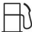
WARNING/DANGER Fuel (Gasoline)

Read, Understand and Follow Instruction Manual

Forbidden Emergency Stop

No Smoking First Aid

No Open Flame Recycling

Protective Gloves must be Worn ON/START

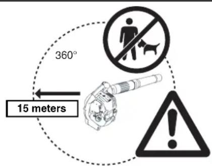
Keep the Area of Operation Clear of All Persons and Pets

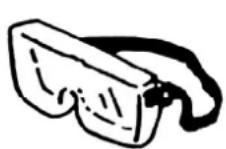
Wear Eye and Ear Protection
Engine-manual Start





OFF/STOP

Severing of fingers or hand, impeller blade


General Instructions
- To ensure correct and safe operation, the user must read, understand and follow this instruction manual to assure familiarity with the handling of the blower (1). Users insufficiently informed will risk danger to themselves as well as others due to improper handling.
- It is recommended only to loan the blower to people who have proven to be experienced with blowers.
• Always hand over the instruction manual. - First-time users should ask the dealer for basic instructions to familiarize oneself with the handling of a blower.
- Children and young persons aged under 18 years must not be allowed to operate the blower. Persons over the age of 16 years may however use the tool for the purpose of being trained only while under the direct supervision of a qualified trainer.
- Use blowers with the utmost care and attention.
- Operate the blower only if you are in good physical condition.
- Perform all work conscientiously and carefully. The user has to accept responsibility for others.
- Never use the blower while under the influence of alcohol or drugs (2).
- Do not use the unit when you are tired.
- Save these instructions for future referral.
Personal Protective Equipment
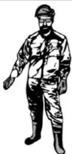
- The clothing worn should be functional and appropriate, I. e. It should be tight-fitting but not cause a hindrance. Do not wear jewelry, clothing or long hair which could be drawn into the air intake.
- In order to avoid head-, eye-, hand- or foot injuries as well as to protect your hearing the following protective equipment and protective clothing must be used during operation of the blower.
Pay particular attention to the following regulations
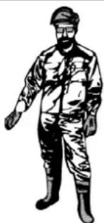
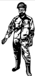
- Clothing must be sturdy and snug-fitting, but allow complete freedom of movement. Avoid loose-fitting jackets, flared or cuffed pants, scarf, unconfined long hair or anything that could be drawn into the air intake. Wear overalls or long pants to protect your legs. Do not wear shorts. (4)
- Blower noise may damage your hearing. Wear sound barriers (ear plugs or ear mufflers) to protect your hearing. Continual and regular users should have their hearing checked regularly. (3)
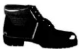
- Use of gloves when working with the blower is recommended. Good footing is most important. Wear sturdy shoes with non slip soles. (4)
- Proper eye protection is a must. Even though the discharge is directed away from the operator, ricochets and bounce backs can occur during blower operation. (3)
- Never operate a blower unless wearing goggles or properly fitted safety glasses with adequate top and side protection which comply with ANSI Z 87.1 (or your applicable national standard).
Starting up the blower
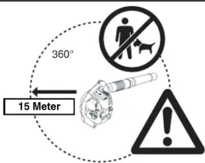
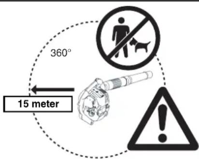
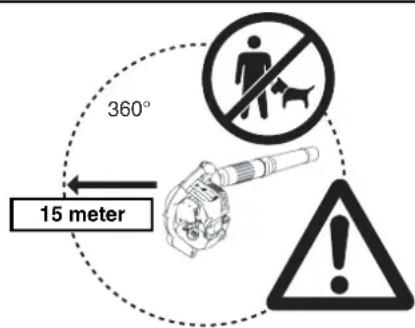
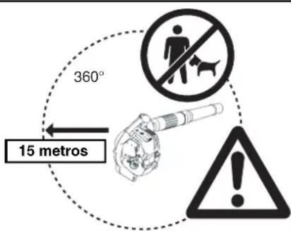
- Please make sure that there are no children or other people within a working range of 15 meters (5), also pay attention to any animals in the working vicinity. Never use the blower in urban areas.
- Before operating, always check that the blower is safe for operation: Check the security of the throttle lever. The throttle lever should be checked for smooth and easy action. Check for proper functioning of the throttle lever lock. Check for clean and dry handles and test the function of the I-O switch. Keep handles free of oil and fuel.


(1)

natural_image
Black-and-white illustration of wine bottles and a crossed glass, no text or symbols present(2)

(3)

natural_image
Illustration of a person in winter clothing and hat, standing with one hand extended (no text or symbols)
(4)
Start the Blower only in accordance with the instructions.
Do not use any other methods for starting the engine (6)!
- Use the blower and the tools supplied only for applications specified.
- Start the blower engine only after the entire tool has been assembled. Operation of the tool is permitted only after all the appropriate accessories are attached.
- The engine is to be switched off immediately if there are any engine problems.
- When working with the blower, always wrap your fingers tightly around the handle, keeping the control handle cradled between your thumb and forefinger. Keep your hand in this position to have your machine under control at all times. Make sure your control handle (and grip for vacuum attachment) are in good condition and free of moisture, pitch, oil or grease.
Always ensure a safe, well-balanced footing.
- Operate the blower in such a manner as to avoid inhalation of the exhaust gases. Never run the engine in enclosed rooms (risk of suffocation and gas poisoning). Carbon monoxide is an odorless gas. Always ensure there is adequate ventilation.
- Switch off the engine when resting and when leaving the blower unattended. Place it in a safe location prevent danger to others, setting fire to combustible materials, or damage to the machine.
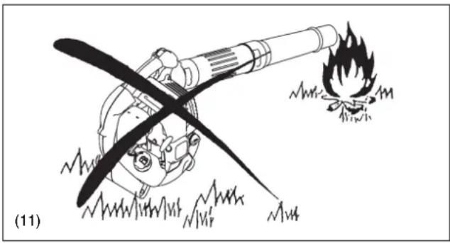
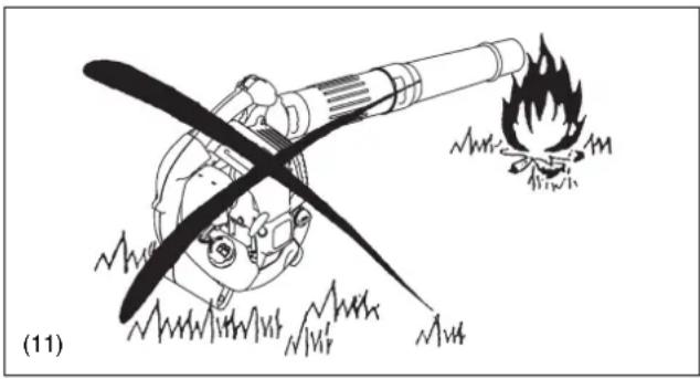
- Never lay the hot blower onto dry grass or onto any combustible materials.
- All protective parts and guards supplied with the machine must be used during operation.
- Never operate the engine with a faulty exhaust muffler.
- Shut off the engine during transport (7).
- Position the blower safely during car or truck transportation to avoid fuel leakage.
- When transporting the blower, ensure that the fuel tank is completely empty.
Refuelling
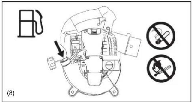
- Shut off the engine during refuelling (7), keep well away from open flame (8) and do not smoke.
- Avoid skin contact with petroleum products. Do not inhale fuel vapor. Always wear protective gloves during refuelling. Change and clean protective clothing at regular intervals.
• Take care not to spill either fuel or oil in order to prevent soil contamination (environmental protection). Clean the blower immediately after fuel has been spilt. Allow wet cloths to dry before disposing in properly, covered container to prevent spontaneous combustion. - Avoid any fuel contact with your clothing. Change your clothing immediately if fuel has been spilled on it (fire hazard).
- Inspect the fuel cap at regular intervals making sure that it stays securely fastened.
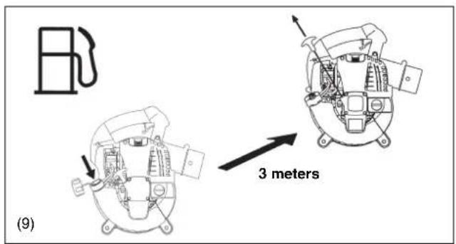
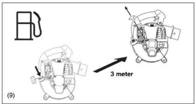
- Carefully tighten the locking screw of the fuel tank. Change locations to start the engine (at least 3 meters away from the place of refuelling) (9).
- Never refuel in closed rooms. Fuel vapors accumulate at ground level (risk of explosions)
- Only transport and store fuel in approved containers. Make sure stored fuel is not accessible to children.
- Do not attempt to refuel a hot or a running engine.

natural_image
Technical line drawing of a mechanical assembly with no visible text or symbols

Method of operation
- Use the blower only in good light and visibility. During cold seasons beware of slippery or wet areas, ice and snow (risk of slipping). Always ensure a safe footing.
- Never work on unstable surfaces or steep terrain.
- To reduce the risk of personal injury, do not direct air blast towards bystanders, since the high pressure of the air flow could injure eyes and could blow small objects at great speed.
- Never insert any foreign object into the air intake of the machine or into the nozzle of the blower. It will damage the fan wheel and may cause serious injury to the operator or bystanders as a result of the object or broken parts being thrown out at high speed.
- Pay attention to the direction of the wind, i.e., do not work against the wind.
- To reduce the risk of stumbling and loss of control, do not walk backward while operating the machine.
- Always shut off the engine before cleaning or servicing the unit or replacing parts.
Maintenance instructions
- Be kind to the environment. Operate the blower with as little noise and pollution as possible. In particular check the correct adjustment of the carburetor.
- Clean the blower at regular intervals and check that all screws and nuts are securely tightened.
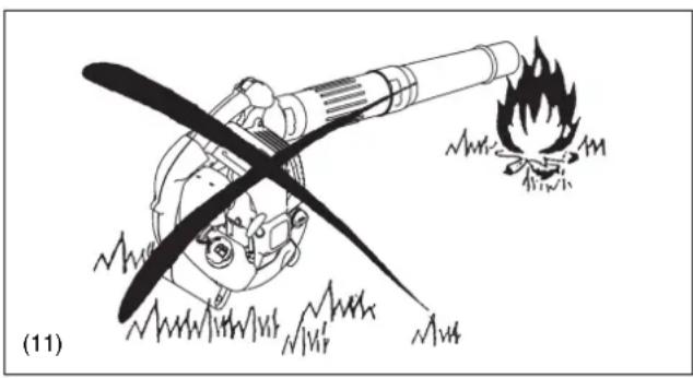
- Never service or store the blower in the vicinity of open flames, sparks, etc. (11).
- Always store the blower in a well-ventilated locked room and with an emptied fuel tank.
Observe and follow all relevant accident prevention instructions issued by the trade associations and by insurance companies. Do not perform any modifications to the blower as this will risk your safety.
The performance of maintenance or repair work by the user is limited to those activities as described in this instruction manual. All other work is to be done by Authorized Service Agents.
Use only genuine spare parts and accessories supplied by Makita.
Use of non-approved accessories and tools means increased risk of accidents and injuries. Makita will not accept any liability for accidents or damage caused by the use of any non-approved attachment or accessories.
First Aid
In case of accident make sure that a well-stocked first-aid kit is available in the vicinity of the operations. Immediately replace any item taken from the first aid kit.
When asking for help, please give the following information:
- Place of accident
• What happened
• Number of injured persons - Extent of injuries
- Your name
Packaging
The Makita blower is delivered in a protective cardboard box to prevent shipping damage. Cardboard is a basic raw material and is therefore consequently reusable or suitable for recycling (waste paper recycling).


(10)

natural_image
Illustration of a cartoon character with a long propeller and explosion sparks, no text or symbols present
natural_image
Simple black cross symbol inside a square frame, labeled (12) at bottom left (no text or numbers on the symbol itself)For European countries only
The EC declaration of conformity is included as Annex A to this instruction manual.
SPECIFICATIONS
| Model BHX2501 BHX2501 with vacuum set | ||||
| Mass (without blower pipe) (kg) 4.5 | ||||
| Dimension (without blower pipe L x W x H) (mm) 350 × 231 × 368 | ||||
| Max. engine speed (min -1) 7 | 800 | |||
| Idling speed (min -1) 3 | 500 | |||
| Engine displacement (mL) 24.5 | ||||
| Fuel Automobile gasoline | ||||
| Fuel tank capacity (L) 0.52 | ||||
| Engine oil | SAE 10W-30 oil of API Classification, Class SF or higher(4-stroke engine for automobile) | |||
| Engine oil volume (L) 0.08 | ||||
| Carburetor (Diaphragm-carburetor) | WALBRO WYL | |||
| Ignition system | Solid state ignition | |||
| Spark plug | NGK CMR6A | |||
| Electrode gap (mm) | 0.7 - 0.8 | |||
| Vibration per ISO22867(*Left hand/Right hand) | ahv eq (m/s2) | 9.3 | 8.1/11.1* | |
| Uncertainty K (m/s2) | 0.5 | 0.5/1.3* | ||
| Sound pressure level average to ISO22868 | LPA eq dB(A) | 90.8 | 92.8 | |
| Uncertainty K dB(A) | 1.4 | 3.8 | ||
| Sound power level average to ISO22868 | LWA eq dB(A) | 104.4 | 104.3 | |
| Uncertainty K dB(A) | 1.6 | 1.5 | ||
Notes:
1. Use the oil and spark plug specified by Makita.
2. This specification is subject to change without prior notice.



Vacuum set (Optional)

natural_image
Line drawing of a handbag with handle and label (no text or symbols)| DESIGNATION OF PARTS DESIGNATION OF PARTS DESIGNATION OF PARTS | |||
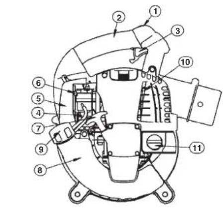
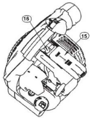
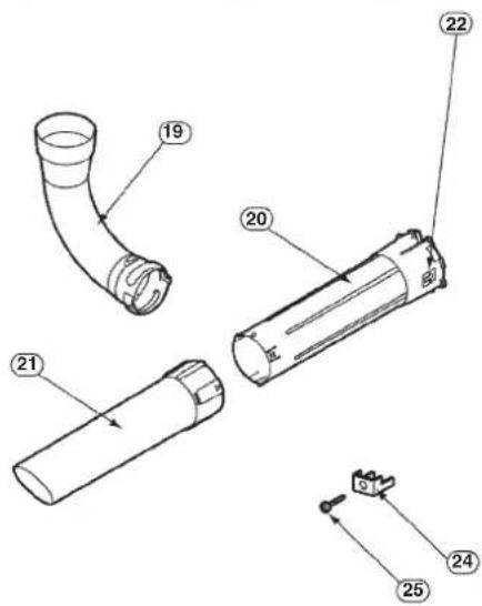
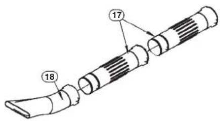
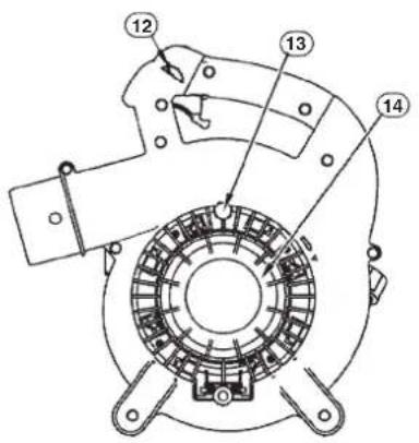
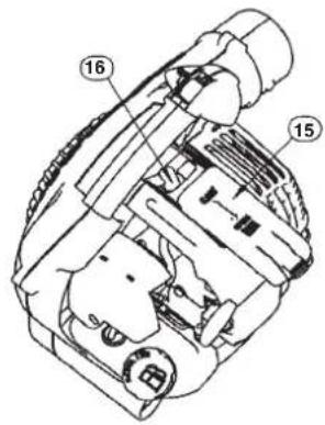
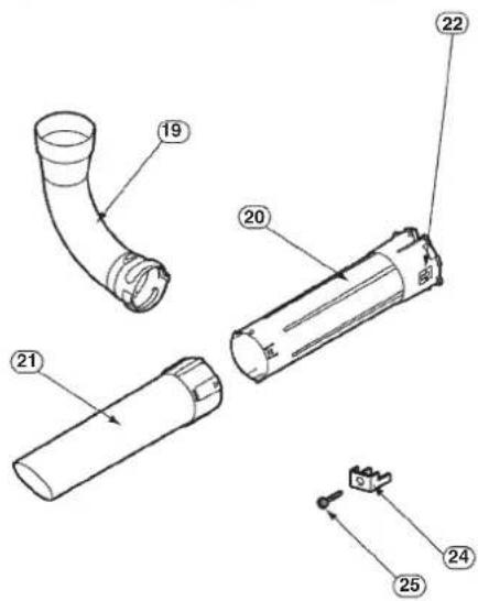
| 1. Stop switch 8. Fuel Tank / Assist Handle 15. Plug Cover 22. Arrow Mark | |||
| 2. Main Handle 9. Fuel Tank Cap 16. Spark Plug 23. Dust Bag | |||
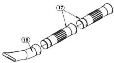
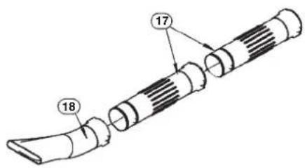
| 3. Trigger Lever 10. Muffler 17. Blower Tube 24. Bracket | |||
| 4. Primer Pump 11. Oil Cap 18. Blower Nozzle 25. Screw | |||
| 5. Air Cleaner Cover 12. Throttle lock button 19. Elbow | |||
| 6. Choke Lever 13. Screw 20. Vacuum Pipe A | |||
| 7. Starter Handle 14. Protector 21. Vacuum Pipe B | |||
CAUTION : Before performing any work on the blower, always stop the engine and pull the spark plug connectors off the spark plug. Always wear protective gloves!
CAUTION : Start the blower only after having assembled it completely.
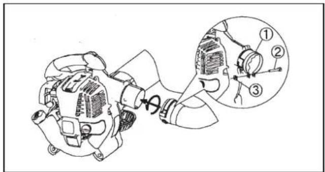
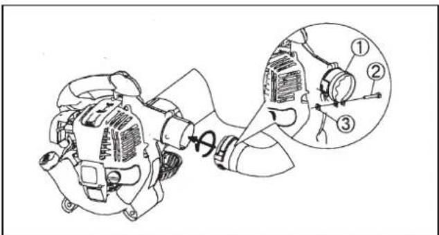
1. ASSEMBLY OF BLOWER PIPES
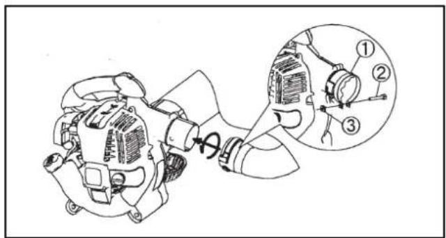
1) Align grooves in the blower pipe with pegs on the blower housing and slide the pipe onto housing.
2) Turn the blower pipe clockwise to lock it into place.
3) Place clamp ① around the opening of the blower pipe. Fasten securely with bolt ② and nut . ③
2. ASSEMBLY OF VACUUM ATTACHMENT
1) Installing Vacuum pipe (nozzle)
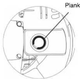
(1) Loosen the screw ④ and open the protector . ⑤

WARNING!
When using the blower for blowing operation, always close the protector and tighten the screw before operation.
Otherwise the bare impeller may catch your body or clothing and cause serious injury.
Always use the vacuum pipe A and B together. Otherwise contact with the impeller may cause serious injury when the operator attempts to remove jammed debris in the pipe.
(2) Align “▲” mark on the vacuum pipe A and B. Insert the vacuum pipe A into the vacuum pipe B until three latches snap in.
(3) Align the ◆ indicated on the vacuum pipe A with the “” ● indicated on the blower. Then insert the vacuum pipe into the blower.
(4) Turn the vacuum pipe until the □ is aligned with the “” ▼ indicated on the blower to lock the vacuum pipe.
(5) Fasten the vacuum pipe securely to the blower with screw ⑦ and bracket ⑥ Do not tighten the screw too much to avoid parts breakage.
Caution: Do not perform the fastening operation in (5) above if the blower is to be used in a country or region where the CE mark is not applicable.
Note: The engine will not start unless the vacuum pipe is mounted completely.
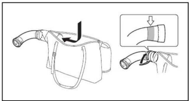
2) Installing Elbow and Dust Bag
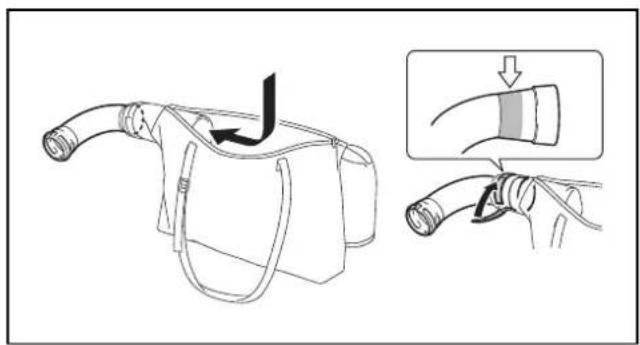
(1) Open the fastener of the dust bag.
(2) Insert the elbow's railed side into the dust bag, take it out through the bag's entry.
(3) Fasten the elbow with hook-and-loop fastener around the place indicated in the figure.
CAUTION
Install the dust bag away from railed side of the elbow. If the dust bag is placed near the engine, the exhaust gas may scorch the dust bag.
(4) Install the elbow on the blower.
(5) Place clamp ① around the opening of the elbow. Fasten securely with bolt ② and nut . ③
Caution: Do not perform the fastening operation in (5) above if the blower is to be used in a country or region where the CE mark is not applicable.

WARNING!
Do not attempt to pick up large wood chips, metals, glass, stones, liquids, lighted cigarettes, fire works or the like.


1. Inspection and Refill of Engine Oil
(1) Perform the following procedure when the engine is cool.
Assure engine is on a flat horizontal surface as shown in Figure 1.
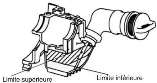
- Inspection: Remove the oil cap. Wipe clean the oil level indicator. Reinstall the oil cap (Figure 2) and remove. Confirm if the oil is between the lower or upper limit of the oil indicator.
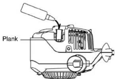
- Refill: After inspection if the oil is below the lower limit add oil through the same opening that the oil cap was removed. See Figure 4 on how to orient the engine to refill the oil.
(2) You may need to refill oil approximately every 10 hours of use (every 10 refuellings).
(3) If the oil changes in color or mixes with dirt, replace the oil. (For the interval and method of replacement, refer to P. 15)
Recommended oil: SAE 10W-30 oil of API Classification, Class SF or higher (4-stroke engine for automobile)
Oil volume: Approx. 0.08 L
Inspection method of engine oil

natural_image
Technical line drawing of a mechanical device with no visible text or symbolsFigure 1

Figure 2
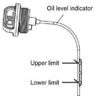
Figure 3
NOTE
- If the engine is not positioned as in Figure 1 on a horizontal surface, an inaccurate indication of oil level may occur.
- If the oil is filled above the limit, oil may be contaminated or may catch fire with white smoke.
Replacement of Oil "Oil Gauge"
- Remove dust or dirt near the oil refill port, and detach the oil gauge.
- Keep the detached oil gauge free of sand or dust. Otherwise, any sand or dust adhering to the oil gauge may cause irregular oil circulation or wear on the engine parts, which will result in troubles.
- As an example to keep the oil gauge clean, it is recommended to insert the oil gauge on its knob side into the engine cover.

natural_image
Technical line drawing of a mechanical component with no visible text or symbolsFigure 4
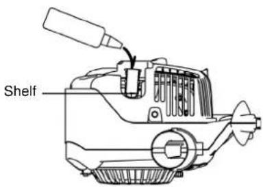
Figure 5

Figure 6
After refilling oil
- Wipe with a rag any spilled oil.
2. Fuel supply

WARNING
- When refuelling the unit, be sure to observe the following instructions to prevent ignition or fire:
- Fuel supply must be made in a place free of fire. Never bring the fire (smoking, etc.) near the place of fuel supply.
- Stop the engine and allow the engine to cool down before refuelling.
- Open the fuel tank cap slowly. The fuel may be spilled out under internal pressure.
- Take care not to spill the fuel. Any spilled fuel must be wiped clean.
- Carry out fuel supply in a well-ventilated place.
- Handle the fuel with care.
- Fuel sticking to the skin or entering an eye may cause allergies or irritation. When any physical abnormality is detected, consult the medical specialist immediately.
- DO NOT put oil in the fuel tank.
STORAGE PERIOD OF FUEL
Fuel should be used within a period of 4 weeks, even if it is kept in a special container in a well-ventilated shaded area. If a special container is not used or if the container is not covered, fuel may deteriorate in one day.
Storage of machine and refill tank
- Keep the machine and tank at a cool place free from direct sunshine.
- Never keep the fuel in a car.
FUEL
The engine is a four-stroke engine. Be sure to use an automobile gasoline (regular gasoline or premium gasoline).
Points for Fuel
- Never use a gasoline mixture which contains engine oil. Otherwise, it will cause excessive carbon accumulation or mechanical troubles.
- Use of deteriorated oil will cause irregular startup.
When refuelling, be sure to stop the engine and confirm that the engine cools down.
REFUELLING METHOD
- Loosen the tank cap a little to release the tank pressure.
- Detach the tank cap, and refuel, discharging air by tilting the fuel tank so that the refuel port will be oriented upward. (DO NOT fill fuel up to the top of the tank.)
• After refuelling, securely tighten the tank cap. - If there is any flaw or damage on the tank cap, replace it.
- The tank cap wears out in course of time. Replace it every two to three years.
• DO NOT put fuel in the oil fill port.
1. Starting

WARNING
- Never attempt engine start in a place where the fuel has been supplied.
- If may cause ignition or fire. When starting the engine, keep a distance of at least 3 m.
- Exhaust gas from the engine is toxic. Do not operate the engine in a poorly-ventilated place, such as in a tunnel, building, etc.
- Operating the engine in the poorly-ventilated place may cause poisoning by exhaust gas.
• In case of detection of any abnormality in sound, odor, vibration after start, stop the engine immediately and carry out inspection. - If the engine is operated without attending such abnormality, an accident may occur.
- Confirm that the engine stops when the stop switch is set to "O" position.
1) When the engine is cold or after refuelling
(1) Set this machine on a flat space.
(2) Set the stop switch to "I" position (Figure 1).
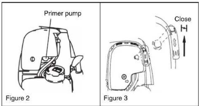
(3) Continue to push the primer pump until fuel comes into the primer pump (Figure 2).
- In general, fuel enters into the carburetor by 7 to 10 pushes.
- If the primer pump is pushed excessively, an excess of gasoline returns to the fuel tank.
(4) Lift the choke lever to the closed position (Figure 3).
(5) Hold the main handle with left hand to prevent the engine from moving.
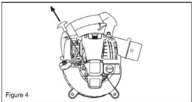
(6) Pull out slowly the starter handle till a certain resistance is felt. Return the starter handle backward once from this position, then pull it out with force (Figure 4).
- Never pull the rope to the full extension.
- Once the start knob is pulled, never release your hand immediately. Hold the start knob until it returns to its original point.
(7) When the engine starts, open the choke lever (Figure 5).
- Open the choke lever progressively while checking the engine operation. Be sure to open the choke lever to the full in the end.
- In cold or when the engine is cooled down, never open the choke lever suddenly. Otherwise, the engine may stop.
(8) Continue warm-up operation for 2 to 3 minutes.
(9) Warm-up is complete when there is quick engine acceleration from low rpm to full throttle.

Figure 1
natural_image
Technical line drawing of a mechanical device with no visible text or symbols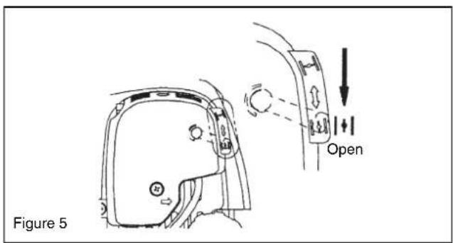
NOTE
- The engine may be damaged if the choke lever is moved further beyond the "CLOSE" position.
- If the engine fires and stops, return this lever to the "OPEN" position and pull the starter handle several times to start the engine again.
- If the operator keeps pulling the starter handle several times with the choke lever left in the "CLOSE" position, the engine may be difficult to start because of flooding of the fuel.
- In case of flooding of the fuel, remove the spark plug and pull the handle several times rapidly to discharge any excess fuel. Dry the spark plug electrode.
- When the throttle valve does not return to a position in contact with the idling adjusting screw even if the throttle lever is set to the low speed, correct the control cable catching state to ensure proper return of the valve.
2) When the engine is warm
(1) Place the engine on a flat ground.
(2) Press the primary pump several times.
(3) Confirm that the choke lever is open.
(4) Hold the main handle with left hand to prevent the engine from moving.
(5) Pull out slowly the starter handle till a certain resistance is felt. Return the starter handle backward once from this position, then pull it out with force.
(6) When the engine is difficult to start, open the throttle valve by about 1/3.
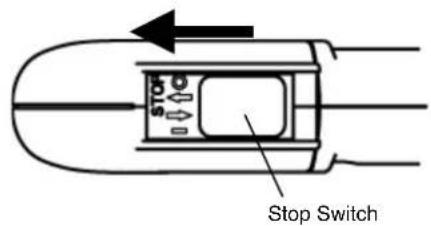
2. Stopping
Release the trigger lever to reduce the engine speed, and set the stop switch to the "O" position.
(Release throttle lever lock if it is locking the trigger lever in the fully open position.)
ADJUSTMENT OF IDLING


DANGER
The carburetor is factory adjusted. Please do not adjust other than idling adjusting. When adjustment becomes necessary, please consult your dealership or an authorized service agent.
Checkup of low-speed rotation
Set the low-speed rotation to 3500 rpm (min ^-1 ).
- If it is necessary to change the rotation speed, regulate the adjusting screw, with Phillips screwdriver.
- Turn the adjusting screw to the right, and the engine speed will increase. Turn the adjusting screw to the left, and the engine speed will drop.

Prevention from carburetor icing
NOTICE
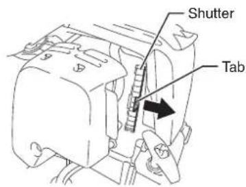
When environmental temperature is higher than 10^ C, always close the shutter (normal setting).
Otherwise the engine may be damaged by overheating.
When the environmental temperature is low and humidity is high, water vapor may freeze inside the carburetor and the engine drives unsteadily (carburetor icing).
Change the setting of the shutter as follows as necessary.
• Warmer environment than 10°C
Hold the tab on the shutter and slide it to the left (closed position).

- 10^ C or colder environment
Hold the tab on the shutter and slide it to the right (open position).
OPERATION METHOD

1. Blower operation
- Hold the machine firmly during operation.
- Direct the nozzle end toward the object to be dusted and pull the trigger lever.
- Fully pull the trigger lever, hold down the throttle lock button and release finger from the trigger lever to lock the trigger lever at full throttle.
- Pull the trigger lever again to release the throttle lock.
- The lower portion of the fuel tank acts as an assist handle, which enables operation with both hands. In this case, be sure to hold the assist handle with a right hand.

natural_image
Line drawing of a person using a handheld air conditioner (no text or symbols)
natural_image
Line drawing of a person using a handheld power shaver (no text or symbols)2. Dust Collection Operation

WARNING
- Do not allow kerosene, gasoline, or lighted cigarette to be sucked into the machine. - Otherwise, fire may occur.
- Do not allow foreign materials, such as large wood chips, metals, glass, pebbles, etc., to be sucked into the machine.
- Otherwise, failure may occur.
• Overfilling of the dust bag may cause its overflow toward the engine side. Empty the bag before it becomes completely full. -
Otherwise, fire may occur.
-
Carry the dust bag belt on the shoulder and adjust the belt length to ensure easy operation.
- Confirm that the dust bag is not twisted and pull the trigger lever to start dust collection.
- When the dust bag is full, remove the dust bag from the machine and open the fastener to empty the bag.

natural_image
Line drawing of a person in protective gear using a large spray gun (no text or symbols)| NOTE | |
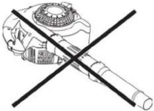
| If this machine is operated with the protector oriented upwards or the main handle downwards, white smoke may appear, oil may be contaminated or oil may leak. | |
 |  |
 |  |

DANGER
- Before inspection and maintenance, stop the engine and allow it to cool. Remove the spark plug and plug cap.
- If inspection or maintenance is attempted immediately after engine stop or with the plug cap left attached, the operator may suffer burn or an accident due to careless startup.
• After inspection and maintenance, be sure to confirm that all parts are assembled. Then, proceed to operation.
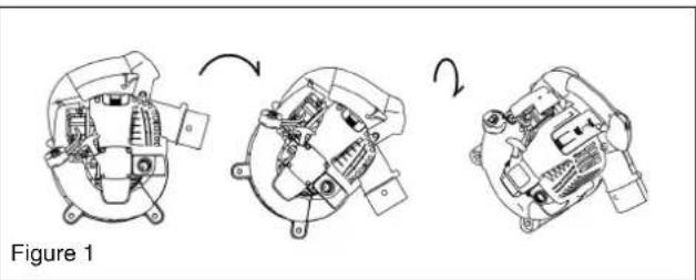
1. Replacement of engine oil
Deteriorated engine oil will shorten the life of the sliding and rotating parts to a great extent. Be sure to check the period and quantity of replacement.

DANGER
- In general, the engine main unit and engine oil still remain hot just after the engine is stopped. In replacement of oil, confirm that the engine main unit and engine oil are sufficiently cooled down. Otherwise, there may remain a risk of scald. Allow sufficient time after stopping engine for the engine oil to return to the oil tank to ensure accurate reading of the oil level indicator.
- If the oil filled above the limit, it may be contaminated or may catch fire with white smoke.
Interval of replacement: After first 20 operating hours, followed by every 50 operating hours
Recommended oil: SAE10W-30 oil of API Classification SF Class or higher (4-stroke engine oil for automobile)
In replacement, perform the following procedure.
(1) Confirm that the tank cap is tightened securely.
(2) Detach the oil cap.
- Keep the oil gauge free from dust or dirt.
(3) Tilt the machine in order as shown in Figure 1.
- Drain the oil in a container.
(4) Orient the machine as shown in Figure 2 and refill oil to the shelf inside the oil pipe.
(5) After refill, securely tighten the oil gauge. Insufficient tightening of the oil gauge will lead to oil leakage.
natural_image
Three-step mechanical assembly diagram showing progressive assembly from top to bottom view (no text or labels)
Points in replacement of engine oil
- Never discard replaced engine oil in garbage, earth or sewage ditch. Disposal of oil is regulated by law. In disposal, always follow the relevant laws and regulations. For any points remaining unknown, contact Authorized Service Agent.
- Oil will deteriorate even when it is kept unused. Perform inspection and replacement at regular intervals (replace with new oil every 6 months).
2. Cleaning of air cleaner

WARNING: INFLAMMABLES STRICTLY PROHIBITED
Interval of Cleaning and Inspection: Daily (every 10 operating hours)
(1) Remove the air cleaner cover-fixing bolts.
(2) Pull the cover lower side and detach the air cleaner cover.
(3) Turn the choke lever to the full close side, and keep the carburetor off from dust or dirt.
(4) If oil adheres to the element (sponge), squeeze it firmly.
(5) For heavy contamination:
- Remove the element (sponge), immerse it in warm water or in water-diluted mild detergent, and dry it completely.
- Clean the element (felt) with gasoline, and dry it completely.
(6) Before attaching the element, be sure to dry it completely. Insufficient drying of the element may lead to difficult startup.
(7) Wipe out with waste cloth, oil adhering around the air cleaner cover and plate breather.
(8) Immediately after cleaning is finished, attach the air cleaner cover and tighten it with fixing bolts. (In remounting, first place the upper claw, and then the lower claw.)


DANGER
- Clean the element several times a day, if excessive dust adheres to it.
- If operation continues with the element remaining not cleared of oil, oil in the air cleaner may fall outside, resulting in oil contamination.
3. Checking the spark plug
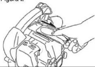
(1) Opening/closing the plug cover When opening the cover, apply fingers to the main handle and plug cover projection (Figure 1). Push up the projection and slide the cover in the "OPEN" direction (Figure 2). When closing the cover, slide the cover in the "CLOSE" direction till the click under the plug cover projection rides over the engine cover. Finally, push in the projection.
(2) Removing the spark plug Use an attached box wrench to remove or install the spark plug (Figure 3).
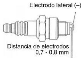
(3) Checking the spark plug The clearance between two electrodes of spark plug is 0.7 to 0.8 mm (Figure 4). Adjust to the correct clearance when it is too wide or too narrow. Clean thoroughly or replace the spark plug if it has accumulated carbon or contaminated.
(4) Replacing the spark plug For replacement, use NGK-CMR6A.

natural_image
Illustration of a hand holding a device with a circular component, labeled 'Figure 1' (no text or symbols on the diagram itself)Figure 3
Figure 2

natural_image
Line drawing of a mechanical device with hands operating it (no text or symbols)Figure 4

natural_image
Technical line drawing of a mechanical assembly (no text or symbols visible)Lateral electrode (−)

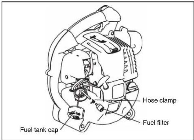
4. Cleaning the fuel filter
- Clogged fuel filter may cause difficulty of startup or failure of engine speed increase.
- Check the fuel filter regularly as follows:
(1) Remove the fuel tank cap, drain the fuel to empty the tank. Check the tank inside for any foreign materials. If any, wipe clean such materials.
(2) Pull out the fuel filter using a wire through the fuel filling port.
(3) If the fuel filter surface is contaminated, clean it with gasoline. The gasoline used for the cleaning must be disposed of according to the method specified by each local authority. Excessively contaminated filter must be replaced.
(4) Reset the fuel filter in the fuel tank and tighten firmly the fuel tank cap. For replacement, contact your dealership or an authorized service agent.
5. Inspection of bolts, nuts and screws
• Retighten loose bolts, nuts, etc.
- Check for fuel and oil leakage.
- Replace damaged parts with new ones for safety operation.
6. Cleaning of parts
- Keep engine clean by wiping down with a cloth rag.
- Keep the cylinder fins free of dust or dirt. Dust or dirt adhering to the fins will cause seizure.
7. Replacement of gaskets and packings
Replace gaskets and packings if the engine is disassembled.
Any maintenance of adjustment work that is not included and described in this manual is only to be performed by Authorized Service Agents.
STORAGE
| WARNING |
| ·When draining the fuel, be sure to stop the engine and confirm that the engine cools down.- Failure to do so may cause burns or fire. |
| DANGER |
| ·When you store the machine for a long time, drain all fuel from the fuel tank and carburetor, and keep it at a dry and clean place. |
Drain fuel from the fuel tank and carburetor according to the following procedure:
(1) Remove the fuel tank cap, and drain fuel completely. If there is any foreign matter remaining in the fuel tank, remove it completely.
(2) Pull out the fuel filter from the refill port using a wire.
(3) Push the primer pump until fuel is drained from there, and drain fuel coming into the fuel tank.
(4) Reset the filter to the fuel tank, and securely tighten the fuel tank cap.
(5) Then, continue to operate the engine until it stops.
(6) Remove the spark plug, and drip several drops of engine oil through the spark plug hole.
(7) Gently pull the starter handle so that engine oil will spread over the engine, and attach the spark plug.
(8) Keep the machine with its handle upside.
(9) Keep the drained fuel in a special container in a well-ventilated shade.

natural_image
Technical line drawing of a mechanical assembly with no visible text or symbolsFault location
| Fault | System | Observation | Cause |
| Engine not starting or with difficulty | Ignition system | Ignition spark O.K. | Fault in fuel supply or compression system, mechanical defect |
| No ignition spark STOP-switch operated, wiring fault or short circuit, spark plug or connector defective, ignition module faulty | |||
| Fuel supply | Fuel tank filled | Incorrect choke position, carburetor defective, fuel supply line bent or blocked, fuel dirty. | |
| Compression No compression when pulled over | Cylinder bottom gasket defective, crankshaft seals damaged, cylinder or piston rings defective or improper sealing of spark plug | ||
| Mechanical fault Starter not engaging Broken starter spring, broken parts inside of the engine | |||
| Warm start problems Tank filled ignition spark existing | Carburetor contaminated, have it cleaned | ||
| Engine starts but dies | Fuel supply | Tank filled | Incorrect idling adjustment, carburetor contaminated |
| Fuel tank vent defective, fuel supply line interrupted, cable or STOP-switch faulty | |||
| Insufficient performance | Several systems may simultaneously be affected | Engine idling poor | Air filter contaminated, carburetor contaminated, muffler clogged, exhaust duct in the cylinder clogged |
| Operating timeItem | Before operation | After lubrication | Daily (10h) | 30h 50h | 200h | Shutdown/rest | Corresponding Page | ||
| Engine oil | Inspect/clean | ○ | 9 | ||||||
| Replace | ○*1 | 15 | |||||||
| Tightening parts (bolt, nut) | Inspect | ○ | 17 | ||||||
| Fuel tank | Clean/inspect | ○ | - | ||||||
| Drain fuel | ○*3 | 17 | |||||||
| Throttle lever | Check function | ○ | - | ||||||
| Stop switch | Check function | ○ | 12 | ||||||
| Low-speed rotation | Inspect/adjust | ○ | 12 | ||||||
| Air cleaner | Clean | ○ | 16 | ||||||
| Ignition plug | Inspect | ○ | 16 | ||||||
| Cooling air duct | Clean/inspect | ○ | 17 | ||||||
| Fuel pipe | Inspect | ○ | 17 | ||||||
| Replace | ◎*2 | - | |||||||
| Fuel filter | Clean/replace | ○ | 17 | ||||||
| Clearance between air intake valve and air discharge valve | Adjust | ◎*2 | - | ||||||
| Oil tube | Inspect | ◎*2 | - | ||||||
| Engine overhaul | ◎*2 | - | |||||||
| Carburetor | Drain fuel | ○*3 | 17 |
*1 Perform initial replacement after 20h operation.
*2 For the 200 operating hour inspection, request Authorized Service Agent or a machine shop.
*3 After emptying the fuel tank, continue to run the engine and drain fuel in the carburetor.
Before making a request for repairs, check a trouble for yourself. If any abnormality is found, control your machine according to the description of this manual. Never tamper or dismount any part contrary to the description. For repairs, contact Authorized Service Agent or local dealership.
| State of abnormality Probable cause (malfunction) Remedy | ||
| Engine does not start | Failure to operate primer pump Push 7 to 10 times. | |
| Low pulling speed of starter rope Pull strongly. | ||
| Lack of fuel Feed fuel. | ||
| Clogged fuel filter Clean | ||
| Broken fuel tube Straighten fuel tube | ||
| Deteriorated fuel | Deteriorated fuel makes starting more difficult. Replace with new one. (Recommended replacement: 1 month) | |
| Excessive suction of fuel | Set throttle lever from medium speed to high speed, and pull starter handle until engine starts. If engine will not start still, remove spark plug, make electrode dry, and reassemble them as they originally are. Then, start as specified. | |
| Detached plug cap Attach securely | ||
| Contaminated spark plug Clean | ||
| Abnormal clearance of spark plug Adjust clearance | ||
| Other abnormality of spark plug Replace | ||
| Abnormal carburetor Make request for inspection and maintenance. | ||
| Starter rope cannot be pulled Make request for inspection and maintenance. | ||
| Abnormal drive system | Make request for inspection and maintenance. | |
| Engine stops soonEngine speed does not increase | Insufficient warm-up | Perform warm-up operation |
| Choke lever is set to “CLOSE” although engine is warmed up | Set to “OPEN” | |
| Clogged fuel filter Clean | ||
| Contaminated or clogged air cleaner | Clean | |
| Abnormal carburetor Make request for inspection and maintenance. | ||
| Abnormal drive system | Make request for inspection and maintenance. | |
| Detached throttle wire | Attach securely | |
| Abnormal drive system | Make request for inspection and maintenance. | |
| Engine does not stop. Run engine at idling, and set choke lever to CLOSE. | Detached connector | Attach securely |
| Abnormal electric system | Make request for inspection and maintenance. | |
When the engine does not start after warm-up operation:
If there is no abnormality found for the check items, open the throttle by about 1/3 and start the engine.
Français
natural_image
Illustration of wine bottles and a pen crossed over, with scattered pills nearby (no text or symbols)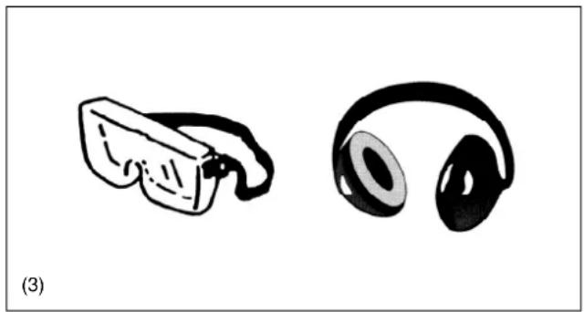
natural_image
Illustration of two types of headphones: a small object and a large headset, both without any text or symbols.
natural_image
Illustration of a person in camouflage uniform standing next to two labeled gloves (no text or symbols present)
natural_image
Technical line drawing of a mechanical assembly with no visible text or symbols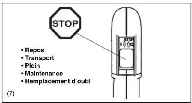
(10)

natural_image
Illustration of a helicopter with a propeller and fire, labeled (11), showing no text or symbols on the diagram itself.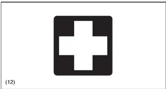
natural_image
Simple black cross symbol inside a square frame, labeled (12) at bottom left (no text or numbers on the symbol itself)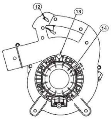


natural_image
Simple line drawing of a handbag with handle and label (no text or symbols)

natural_image
Technical line drawing of a mechanical device with no visible text or symbolsFigure 1
natural_image
Technical line drawing of a mechanical device with no visible text or symbolsFigure 4

Figure 5
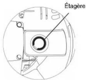
Figure 6
natural_image
Technical line drawing of a mechanical device with internal components and an arrow indicating direction (no text or symbols)
NOTE
natural_image
Line drawing of a person using a handheld air conditioner (no text or symbols)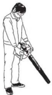
natural_image
Line drawing of a person using a handheld device to clean or adjust equipment (no text or symbols)natural_image
Line drawing of a person in protective gear using a large tool (no text or symbols)NOTE
natural_image
Technical line drawing of a mechanical component with a diagonal cross mark (no text or symbols)
natural_image
Crossed mechanical component symbol with no text or labels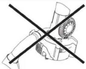
natural_image
Simple line drawing of a crossed-out robot figure (no text or symbols)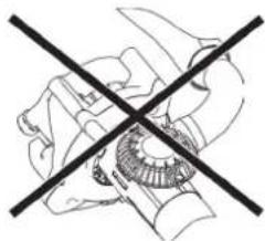
natural_image
Pure mechanical cross-section diagram without any text, numbers, or symbols
DANGER
natural_image
Three-step mechanical assembly diagram showing progressive assembly from top to bottom view (no text or labels)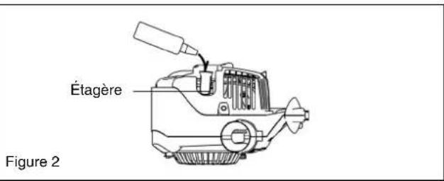
natural_image
Line drawing of a hand holding a tool interacting with a mechanical component (no text or symbols)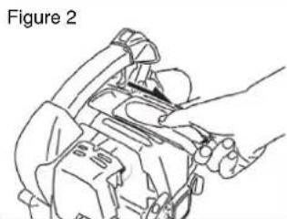
natural_image
Line drawing of a mechanical assembly with hands operating a tool (no text or symbols)
natural_image
Technical line drawing of a mechanical device with no visible text or symbols
natural_image
Technical line drawing of a mechanical device with no visible text or symbolsnatural_image
Black-and-white illustration of wine bottles and a crossed glass, no text or symbols present(2)


(3)
natural_image
Illustration of a person in winter clothing and hat, standing with one hand extended (no text or symbols)

(4)
natural_image
Technical line drawing of a mechanical assembly with no visible text or symbols
(10)

natural_image
Illustration of a helicopter with a propeller and fire extinguisher, no text or symbols present
natural_image
Simple white cross symbol on black background (no text or symbols)(12)


natural_image
Line drawing of a handbag with handle and label (no text or symbols)


natural_image
Technical line drawing of a mechanical device with no visible text or symbols

natural_image
Technical line drawing of a mechanical component with no visible text or symbolsAbbildung 4
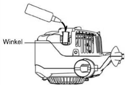
Abbildung 5
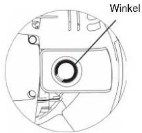
Abbildung 6
natural_image
Technical line drawing of a mechanical assembly with no visible text or symbolsAbbildung 4
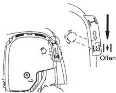
Abbildung 5
ANMERKUNG
natural_image
Diagram of a device with internal components and directional arrow (no text or symbols)Stoppschalter
LEERLAUFEINSTELLUNG


GEFAHR
natural_image
Line drawing of a person using a handheld power tool (no text or symbols)
natural_image
Line drawing of a person using a manual power shaver (no text or symbols)natural_image
Line drawing of a person in protective gear using a large handheld device (no text or symbols)natural_image
Technical line drawing of a mechanical device with no visible text or symbolsFehlererkennung
natural_image
Black-and-white illustration of wine bottles and a crossed glass, no text or symbols present
natural_image
Two black-and-white illustrations: a pair of glasses and a pair of headphones, both without any text or symbols.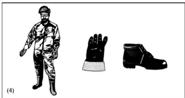
natural_image
Illustration of a person in camouflage uniform standing next to two labeled gloves (no text or symbols present)
natural_image
Technical line drawing of a mechanical assembly with no visible text or symbols
(10)
natural_image
Illustration of a helicopter with a propeller and fire, labeled (11), showing no text or symbols on the diagram itself.
natural_image
Simple white cross symbol on black background (no text or symbols)(12)



natural_image
Line drawing of a handbag with handle and label (no text or symbols)

natural_image
Illustration of a hand holding a sphygmomanometer with a cable, showing a step-down view of the cable being inserted (no text or symbols present)
natural_image
Technical line drawing of a mechanical device with no visible text or symbolsFigura 1
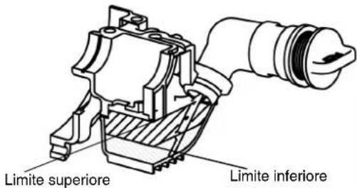
Figura 2

natural_image
Technical line drawing of a mechanical component with no visible text or symbolsFigura 4

Figura 5

Figura 6
natural_image
Line drawing of a mechanical component with no visible text or symbolsFigura 2
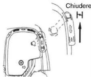
Figura 3

natural_image
Technical line drawing of a mechanical assembly with no visible text or symbolsFigura 4
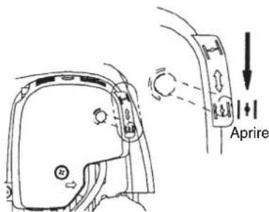
Figura 5
NOTA
natural_image
Diagram of a device with internal components and directional arrow (no text or symbols)natural_image
Line drawing of a person using a handheld air conditioner (no text or symbols)
natural_image
Line drawing of a person using a handheld device to clean or adjust equipment (no text or symbols)natural_image
Line drawing of a person in protective gear using a large tool (no text or symbols)NOTA
natural_image
Line drawing of a tank with a cross mark, no text or symbols present
natural_image
Crossed mechanical component symbol (no text or labels)
natural_image
Simple line drawing of a robot crossed with a diagonal line (no text or symbols)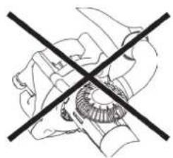
natural_image
Cross-sectional diagram of a mechanical component with no visible text or symbols
PERICOLO
natural_image
Three-step mechanical assembly diagram showing progressive assembly from motor to gear (no text or labels)
natural_image
Illustration of a hand holding a device with a tool, labeled 'Figura 1' (no other text or symbols)Figura 3

natural_image
Technical line drawing of a mechanical assembly (no text or symbols visible)Figura 2

natural_image
Line drawing of a robotic arm gripping a mechanical component (no text or symbols)Figura 4
natural_image
Technical line drawing of a mechanical device with no visible text or symbolsOPBOUWINSTRUCTIES....80
VOOR GEBRUIK....81
BEDIENING 83
AFSTELLINGEN 84
BEDIENINGSMETHODE 85
INSPECTIE EN ONDERHOUD 87
MACHINE-OPSLAG....89
OPLOSSEN VAN PROBLEMEN....91
SYMBOLEN
natural_image
Black-and-white illustration of wine bottles and a crossed glass, no text or symbols present(2)


(3)
natural_image
Illustration of a person in winter clothing and hat, standing with one hand extended (no text or symbols)

(4)
natural_image
Technical line drawing of a mechanical assembly with no visible text or symbols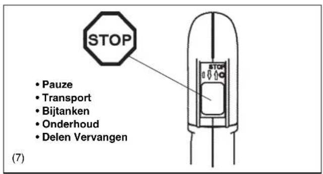
(10)
natural_image
Illustration of a helicopter with a propeller and fire extinguisher, no text or symbols present
natural_image
Simple white cross symbol on black background (no text or symbols)(12)



natural_image
Line drawing of a handbag with handle and label (no text or symbols)| BENAMING VAN ONDERDELEN | BENAMING VAN ONDERDELEN | BENAMING VAN ONDERDELEN | BENAMING VAN ONDERDELEN |
| 1. Stopschakelaar 8. Benzinetank | Hulpgreep 15. Bougiekap 22. Pijlteken | ||
| 2. Hoofdgreep 9. Benzinetankdop | 16. Bougie 23. Stofzak | ||
| 3. Trekker 10. Uitlaat 17. Blaaspijp | 24. Beugel | ||
| 4. Opvoerpomp 11. Oliedop 18. Blaasmond 25. Schroef | |||
| 5. Afdekking luchtfilter 12. Throttle | vergrendelknop 19. Elleboog | ||
| 6. Chokehendel | 13. Schroef | 20. Zuigmond A | |
| 7. Trekstarter | 14. Beschermrooster | 21. Zuigmond B |


natural_image
Technical line drawing of a mechanical device with no visible text or symbols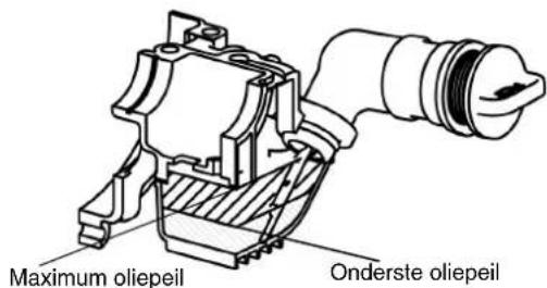
Afbeelding 2

natural_image
Technical line drawing of a mechanical component with no visible text or symbolsAfbeelding 4
Afbeelding 5
Afbeelding 6
natural_image
Diagram of a device with an arrow indicating direction, showing internal components and connections (no text or symbols)Stopschakelaar
AFSTELLINGEN


GEVAAR
natural_image
Line drawing of a person using a handheld air conditioner (no text or symbols)
natural_image
Line drawing of a person using a handheld power shaver (no text or symbols)2. Zuigen

WAARSCHUWING
natural_image
Line drawing of a person in protective gear using a handheld device (no text or symbols)OPMERKING
natural_image
Technical line drawing of a mechanical component with a diagonal cross mark (no text or symbols)
natural_image
Crossed mechanical component symbol (no text or labels)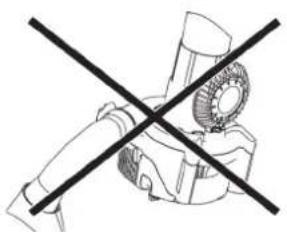
natural_image
Simple line drawing of a robot crossed with a diagonal line (no text or symbols)
natural_image
Cross-sectional diagram of a mechanical component with no visible text or symbols
GEVAAR
natural_image
Line drawing of a mechanical device with hands operating it (no text or symbols)
natural_image
Technical line drawing of a mechanical assembly with no visible text or symbolsStoring lokaliseren
natural_image
Illustration of a wine bottle crossed with a diagonal line, accompanied by a smaller bottle and scattered items (no text or symbols)(2)


(3)

natural_image
Illustration of a person in military-style uniform and cap, standing with one hand extended (no text or symbols)

(4)

natural_image
Technical line drawing of a mechanical assembly with no visible text or symbols
natural_image
Illustration of a person using a fire extinguisher with smoke, no text or symbols present
natural_image
Simple white cross symbol on black background (no text or symbols)(12)


natural_image
Simple line drawing of a handbag with handle and label (no text or symbols)


natural_image
Technical line drawing of a mechanical device with no visible text or symbolsFigura 1

natural_image
Technical line drawing of a mechanical component with no visible text or symbolsFigura 4

Figura 5

Figura 6
Interruptor de paro
Figura 1


NOTA
natural_image
Line drawing of a person using a handheld air conditioner (no text or symbols)
natural_image
Line drawing of a person using a manual power tool to clean or adjust equipment (no text or symbols)natural_image
Line drawing of a person in protective gear using a large tool (no text or symbols)natural_image
Line drawing of a hand holding a device, no text or symbols presentFigura 2
natural_image
Line drawing of a person using a handheld device to interact (no text or symbols present)
natural_image
Technical line drawing of a mechanical device with no visible text or symbolsFigura 4
natural_image
Technical line drawing of a mechanical assembly with no visible text or symbolsnatural_image
Black-and-white illustration of wine bottles and a crossed glass, no text or symbols present(2)

(3)

natural_image
Illustration of a person in winter clothing and hat, standing with one hand extended (no text or symbols)
(4)
natural_image
Technical line drawing of a mechanical assembly with no visible text or symbols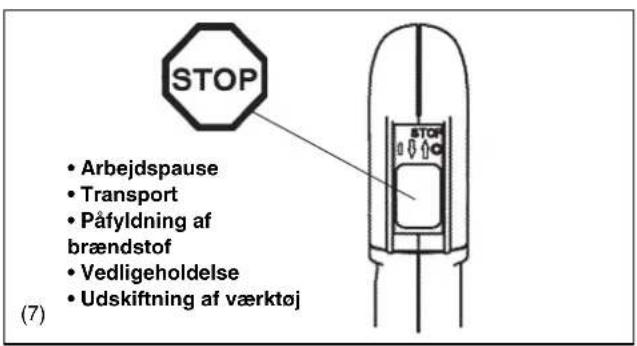
(10)
natural_image
Illustration of a helmet with a propeller and explosion sparks, no text or symbols present
natural_image
Simple white cross symbol on black background (no text or symbols)(12)
Kun for lande i Europa



natural_image
Line drawing of a handbag with handle and label (no text or symbols)

natural_image
Technical line drawing of a mechanical device with no visible text or symbolsFig. 1

Fig. 2
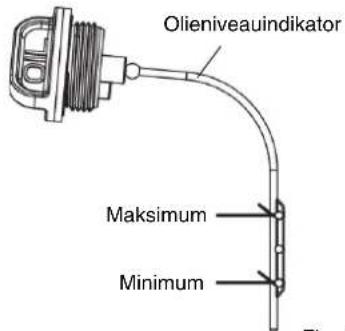
Fig. 3
BEMÆRK
natural_image
Technical line drawing of a mechanical component with no visible text or symbolsFig. 4

Fig. 5

Fig. 6
natural_image
Technical line drawing of a mechanical device with internal components and an arrow indicating direction (no text or symbols)
BEMÆRK
natural_image
Diagram of a device with an arrow indicating direction, showing internal components and connections (no text or symbols)Stop-kontakt
TOMGANGSINDSTILLING


FARE
1. Blæsefunktion
natural_image
Line drawing of a person using a handheld air conditioner (no text or symbols)
natural_image
Line drawing of a person in uniform using a handheld power shaver (no text or symbols)2. Sugefunktionen

ADVARSEL
natural_image
Line drawing of a person in protective gear using a large industrial machine (no text or symbols)natural_image
Three-step mechanical assembly diagram showing internal components and motion, labeled Fig. 1 (no text or symbols on the diagrams themselves)
natural_image
Line drawing of a hand holding a device, no text or symbols present
natural_image
Line drawing of a mechanical assembly with hands adjusting components (no text or symbols)
natural_image
Technical line drawing of a mechanical device component (no text or symbols)
natural_image
Technical line drawing of a mechanical assembly with no visible text or symbolsFejldetektering
natural_image
Black-and-white illustration of wine bottles and a crossed glass, no text or symbols present(2)


(3)
natural_image
Illustration of a person in winter clothing and hat, standing with one hand extended (no text or symbols)

(4)
natural_image
Mechanical assembly diagram showing internal components and directional arrow (no text or labels)
(10)

natural_image
Illustration of a soldier firing a weapon with smoke, labeled (11), showing no text or symbols on the diagram itself.
natural_image
Simple white cross symbol on black background (no text or symbols)(12)
Apenas para países europeus


natural_image
Line drawing of a handbag with handle and label (no text or symbols)

natural_image
Line drawing of a swimmer's head and shoulders with an arrow indicating the grip (no text or symbols present)
natural_image
Technical line drawing of a mechanical device with no visible text or symbolsFigura 1

Figura 2

natural_image
Technical line drawing of a mechanical device with no visible text or symbolsFigura 4

natural_image
Line drawing of a mechanical component with no visible text or symbolsFigura 2

Figura 3

natural_image
Technical line drawing of a mechanical assembly with no visible text or symbols
Figura 5
NOTA
natural_image
Line drawing of a person using a handheld power tool (no text or symbols)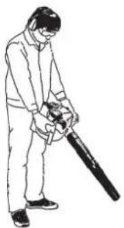
natural_image
Line drawing of a person using a handheld power shaver (no text or symbols)2. Colecta de pó
AVISO
natural_image
Line drawing of a person in protective gear using a large industrial machine (no text or symbols)natural_image
Three-step mechanical assembly diagram showing progressive assembly from top to bottom view (no text or symbols)
natural_image
Line drawing of a hand holding a device, labeled 'Figura 1' (no other text or symbols)Figura 2

natural_image
Line drawing of a person adjusting a mechanical device (no text or symbols)
natural_image
Technical line drawing of a mechanical assembly (no text or symbols)Figura 4

natural_image
Technical line drawing of a mechanical assembly with no visible text or symbols


- INSTRUCTION MANUAL
- INSTRUCTIONS D'EMPLOI
- BETRIEBSANLEITUNG
- MANUALE D'ISTRUZIONI
- GEBRUIKSAANWIJZING
- MANUAL DE INSTRUÇÕES
- Important:
- Importante:
- Table of contents
- General Instructions
- Personal Protective Equipment
- Pay particular attention to the following regulations
- Starting up the blower
- Refuelling
- Method of operation
- Maintenance instructions
- First Aid
- When asking for help, please give the following information:
- Packaging
- For European countries only
- ASSEMBLY OF BLOWER PIPES
- ASSEMBLY OF VACUUM ATTACHMENT
- WARNING!
- 2) Installing Elbow and Dust Bag
- CAUTION
- Inspection and Refill of Engine Oil
- NOTE
- Replacement of Oil "Oil Gauge"
- After refilling oil
- Fuel supply
- WARNING
- STORAGE PERIOD OF FUEL
- Storage of machine and refill tank
- FUEL
- Points for Fuel
- REFUELLING METHOD
- Starting
- 1) When the engine is cold or after refuelling
- 2) When the engine is warm
- Stopping
- ADJUSTMENT OF IDLING
- DANGER
- Checkup of low-speed rotation
- Prevention from carburetor icing
- NOTICE
- OPERATION METHOD
- Blower operation
- Dust Collection Operation
- Replacement of engine oil
- Points in replacement of engine oil
- Cleaning of air cleaner
- WARNING: INFLAMMABLES STRICTLY PROHIBITED
- Interval of Cleaning and Inspection: Daily (every 10 operating hours)
- Checking the spark plug
- Cleaning the fuel filter
- Inspection of bolts, nuts and screws
- Cleaning of parts
- Replacement of gaskets and packings
- STORAGE
- Français
- ANMERKUNG
- LEERLAUFEINSTELLUNG
- GEFAHR
- NOTA
- PERICOLO
- SYMBOLEN
- AFSTELLINGEN
- GEVAAR
- Zuigen
- WAARSCHUWING
- OPMERKING
- Kun for lande i Europa
- BEMÆRK
- TOMGANGSINDSTILLING
- FARE
- Blæsefunktion
- Sugefunktionen
- ADVARSEL
- Apenas para países europeus
- Colecta de pó
- AVISO
Brand : MAKITA
Model : BHX2501X
Category : Blower