
System x3650 M3 - Server IBM - Free user manual and instructions
Find the device manual for free System x3650 M3 IBM in PDF.

| Product Type | 2U Rack Server |
| Brand & Model | IBM System x3650 M3 (Types 4255, 7945, 7949) |
| Dimensions (Height x Width x Depth) | 85.2 mm x 482.0 mm (with bezel) x 729 mm (overall) |
| Weight | 21.09 kg (46.5 lb) to 25 kg (55 lb) depending on configuration |
| Power Supply | Up to two hot-swap AC power supplies: 460W or 675W options; 100-127V or 200-240V auto-selected |
| Processor | Up to two Intel Xeon multi-core; QuickPath Interconnect up to 6.4 GT/s |
| Memory | 18 DIMM slots; DDR3 ECC registered (RDIMM) up to 288 GB or unbuffered (UDIMM) up to 48 GB; 1333/1067/800 MHz |
| Hard Drive Bays | Up to 16 x 2.5-inch SAS hot-swap bays (8 standard + optional 8-bay expansion); 4 x simple-swap SATA SSD bays |
| PCI Expansion | 2 x PCI Express x8 riser cards (x8 lanes each); optional riser cards for PCI-X or x16 |
| Integrated Management | Integrated Management Module (IMM) with IPMI 2.0, SNMP v3, CIM; dedicated management Ethernet; remote presence with optional Virtual Media Key |
| Network | Dual Broadcom BCM5709 Gigabit Ethernet controllers with TCP/IP Offload Engine (TOE); optional dual-port daughter card |
| Operating Temperature | 10°C to 35°C (50°F to 95°F) at altitudes up to 914.4 m (3000 ft) |
| Humidity | 20% to 80% non-condensing (operating) |
| Acoustic Noise | Declared sound power: 6.3 bel (idle), 6.5 bel (operating) |
| Heat Output | Approx 662 Btu/h (minimum) to 2302 Btu/h (maximum) |
| Warranty | 3-year parts and labor (7945/7949); 4-year parts and labor (4255) |
| Maintenance Features | Hot-swap fans, power supplies, hard drives; light path diagnostics; DSA Preboot diagnostics; redundant cooling and power |
| Safety | Complies with safety standards; lithium battery replacement (IBM part 33F8354); laser product precautions |
| Spare Parts & Repairability | Customer-replaceable: hot-swap drives, fans, power supplies, memory, PCI adapters; system board replacement by trained service technician |
| General Information | UEFI-compliant firmware; supports Windows, Linux, VMware hypervisor; IBM Systems Director management |
Frequently Asked Questions - System x3650 M3 IBM
User questions about System x3650 M3 IBM
0 question about this device. Answer the ones you know or ask your own.
Ask a new question about this device
Download the instructions for your Server in PDF format for free! Find your manual System x3650 M3 - IBM and take your electronic device back in hand. On this page are published all the documents necessary for the use of your device. System x3650 M3 by IBM.
USER MANUAL System x3650 M3 IBM
Installation and User's Guide
Installation and User's Guide
Note: Before using this information and the product it supports, read the general information in Appendix B, "Notices," on page 163 the IBM Safety Information and IBM Environmental Notices and User's Guide on the IBM System x Documentation CD, and the IBM Warranty Information document that comes with your server.
Tenth Edition (September 2012)
© Copyright IBM Corporation 2012.
US Government Users Restricted Rights – Use, duplication or disclosure restricted by GSA ADP Schedule Contract with IBM Corp.
Contents
Safety. v i i
Chapter 1. The System x3650 M3 server . . . . . . . . . . . . . . . . . . 1
The IBM Documentation CD . . . . . . . . . . . . . . . . . . . . . . . 3
Hardware and software requirements. 3
Using the Documentation Browser. 3
Related documentation 4
Notices and statements in this document. 6
Features and specifications. 6
What your server offers . . . . . . . . . . . . . . . . . . . . . . . . 8
Reliability, availability, and serviceability features . . . . . . . . . . . . 1 1
IBM Systems Director. 1 2
The UpdateXpress System Pack Installer. 1 3
Server controls, LEDs, and power. 1 3
Front view. 1 4
Rear view. 1 7
Server power features 2 1
Chapter 2. Installing optional devices. 2 5
Instructions for IBM Business Partners 2 5
Server components 2 6
System-board internal connectors 2 8
System-board external connectors. 2 9
System-board switches and jumpers 3 0
System-board LEDs. 3 3
System-board optional device connectors. 3 4
SAS riser-card connectors and LEDs. 3 5
PCI riser-card adapter connectors. 3 6
PCI riser-card assembly LEDs. 3 6
Installation guidelines 3 7
System reliability guidelines. 3 8
Working inside the server with the power on . . . . . . . . . . . . . 3 8
Handling static-sensitive devices 3 9
Internal cable routing and connectors. 40
Removing the cover. 4 5
Removing a PCI riser-card assembly . . . . . . . . . . . . . . . . . 4 6
Installing a PCI riser-card assembly 47
Removing the microprocessor 2 air baffle . . . . . . . . . . . . . . . . 4 8
Installing the microprocessor 2 air baffle . . . . . . . . . . . . . . . . . . 4 9
Removing the DIMM air baffle 50
Installing the DIMM air baffle. 5 1
Installing the full-length-adapter bracket. 5 2
Storing the full-length-adapter bracket . . . . . . . . . . . . . . . . 5 2
Installing a PCI adapter. 5 3
Removing a PCI adapter 5 7
Installing an IBM Virtual Media Key . . . . . . . . . . . . . . . . . . . 5 8
Installing a hard disk drive. 5 9
Removing a hard disk drive 60
Installing a simple-swap hard disk drive. 6 0
Removing a simple-swap hard disk drive 6 2
Installing a SAS/SATA 4 Pac HDD upgrade option . . . . . . . . . . . . . . . . 62
Installing a SAS/SATA 8 Pac HDD option . . . . . . . . . . . . . . . . . . . . . . . . . . . . . . . 68
Installing a SAS/SATA 8 Pac HDD for 2 RAID kit with 2 M5015 adapters option 79
Installing an optional tape drive. 8 9
Converting a 16 bay system to a 8 bay + tape system . . . . . . . . . 9 0
Installing the tape drive option. 9 2
Installing a second microprocessor. 97
Thermal grease . . . . . . . . . . . . . . . . . . . . . . . . . . . 1 0 3
Installing a memory module. 104
DIMM installation sequence. 1 0 6
Memory mirroring. 107
Online-spare memory 109
Installing a DIMM . . . . . . . . . . . . . . . . . . . . . . . . 1 1 0
Installing a hot-swap ac power supply . . . . . . . . . . . . . . . . 1 1 2
Removing a hot-swap fan . . . . . . . . . . . . . . . . . . . . . 1 1 5
Installing a hot-swap fan . . . . . . . . . . . . . . . . . . . . . . . 1 1 6
Removing the SAS riser-card and controller assembly . . . . . . . . . 1 1 7
Installing the SAS riser-card and controller assembly . . . . . . . . . 1 1 8
Removing a ServeRAID SAS controller from the SAS riser-card . . . . . 1 2 1
Installing a ServeRAID SAS controller on the SAS riser-card . . . . . . 1 2 3
Installing an optional ServeRAID adapter advanced feature key . . . . . . 1 2 4
Installing a ServeRAID SAS controller battery on the remote battery tray . . . 126
Moving the SAS controller retention bracket. 1 3 1
Installing a USB hypervisor memory key . . . . . . . . . . . . . . . . 1 3 3
Removing a USB hypervisor memory key . . . . . . . . . . . . . . . 1 3 4
Installing the optional two-port Ethernet adapter 1 3 5
Installing an optional DVD drive . . . . . . . . . . . . . . . . . . . 1 3 8
Completing the installation . . . . . . . . . . . . . . . . . . . . . . 1 3 9
Replacing the server cover. 1 4 0
Connecting the external cables . . . . . . . . . . . . . . . . . . 1 4 1
Updating the server configuration. 1 4 2
Chapter 3. Configuring the server. . . . . . . . . . . . . . . . . . . . . . . . . . 143
Using the Setup utility . . . . . . . . . . . . . . . . . . . . . . . . 1 4 4
Starting the Setup utility . . . . . . . . . . . . . . . . . . . . . 1 4 5
Setup utility menu choices 1 4 5
Passwords. 1 4 8
Using the Boot Selection Menu program . . . . . . . . . . . . . . . 1 4 9
Starting the backup server firmware. 1 5 0
Using the ServerGuide Setup and Installation CD. 1 5 0
ServerGuide features 1 5 0
Setup and configuration overview . . . . . . . . . . . . . . . . . 1 5 1
Typical operating-system installation . . . . . . . . . . . . . . . . 1 5 1
Installing your operating system without using ServerGuide . . . . . . . 152
Using the integrated management module . . . . . . . . . . . . . . 1 5 2
Using the USB memory key for VMware hypervisor . . . . . . . . . . . 1 5 3
Using the remote presence capability and blue-screen capture. . . . . . . 154
Enabling the remote presence feature . . . . . . . . . . . . . . . 1 5 5
Obtaining the IP address for the Web interface access. . . . . . . . . 155
Logging on to the Web interface . . . . . . . . . . . . . . . . . 1 5 5
Enabling the Broadcom Gigabit Ethernet Utility program . . . . . . . . . 1 5 6
Configuring the Gigabit Ethernet controller 1 5 6
Using the LSI Configuration Utility program . . . . . . . . . . . . . . 1 5 7
Starting the LSI Configuration Utility program 1 5 7
Formatting a hard disk drive . . . . . . . . . . . . . . . . . . . 1 5 8
Creating a RAID array of hard disk drives . . . . . . . . . . . . . 1 5 8
IBM Advanced Settings Utility program. 1 5 9
Updating IBM Systems Director 1 5 9
Appendix A. Getting help and technical assistance . . . . . . . . . . 1 6 1
Before you call . . . . . . . . . . . . . . . . . . . . . . . . . . . . . 1 6 1
Using the documentation. 1 6 1
Getting help and information from the World Wide Web . . . . . . . . . 1 6 1
Software service and support . . . . . . . . . . . . . . . . . . . . 1 6 2
Hardware service and support 1 6 2
IBM Taiwan product service. 1 6 2
Appendix B. Notices 1 6 3
Trademarks. 1 6 3
Important notes . . . . . . . . . . . . . . . . . . . . . . . . . . 1 6 4
Particulate contamination. 1 6 5
Documentation format 1 6 5
Telecommunication regulatory statement 1 6 6
Electronic emission notices 1 6 6
Federal Communications Commission (FCC) statement . . . . . . . 1 6 6
Industry Canada Class A emission compliance statement. . . . . . . . 166
Australia and New Zealand Class A statement. 166
European Union EMC Directive conformance statement . . . . . . . 1 6 7
Germany Class A statement. 1 6 7
Japan VCCI Class A statement. 1 6 8
Japan Electronics and Information Technology Industries Association (JEITA) statement 1 6 8
Korea Communications Commission (KCC) statement . . . . . . . . 1 6 8
Russia Electromagnetic Interference (EMI) Class A statement . . . . . . 169
People's Republic of China Class A electronic emission statement . . . . 169
Taiwan Class A compliance statement . . . . . . . . . . . . . . . . 169
Index 171
Safety
Before installing this product, read the Safety Information.
Each caution and danger statement in this document is labeled with a number. This number is used to cross reference an English-language caution or danger statement with translated versions of the caution or danger statement in the Safety Information document.
For example, if a caution statement is labeled “Statement 1,” translations for that caution statement are in the Safety Information document under “Statement 1.”
Be sure to read all caution and danger statements in this document before you perform the procedures. Read any additional safety information that comes with the server or optional device before you install the device.
Attention: Use No. 26 AWG or larger UL-listed or CSA certified telecommunication line cord.
Statement 1:
DANGER
Electrical current from power, telephone, and communication cables is hazardous.
To avoid a shock hazard:
- Do not connect or disconnect any cables or perform installation, maintenance, or reconfiguration of this product during an electrical storm.
- Connect all power cords to a properly wired and grounded electrical outlet.
- Connect to properly wired outlets any equipment that will be attached to this product.
- When possible, use one hand only to connect or disconnect signal cables.
- Never turn on any equipment when there is evidence of fire, water, or structural damage.
- Disconnect the attached power cords, telecommunications systems, networks, and modems before you open the device covers, unless instructed otherwise in the installation and configuration procedures.
- Connect and disconnect cables as described in the following table when installing, moving, or opening covers on this product or attached devices.
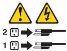
To Connect: To Disconnect:
- Turn everything OFF.
- Turn everything OFF.
- First, attach all cables to devices.
- First, remove power cords from outlet.
- Attach signal cables to connectors.
- Remove signal cables from connectors.
- Attach power cords to outlet.
- Remove all cables from devices.
- Turn device ON.
Statement 2:

CAUTION:
When replacing the lithium battery, use only IBM Part Number 33F8354 or an equivalent type battery recommended by the manufacturer. If your system has a module containing a lithium battery, replace it only with the same module type made by the same manufacturer. The battery contains lithium and can explode if not properly used, handled, or disposed of.
Do not:
- Throw or immerse into water
• Heat to more than 100°C (212°F) - Repair or disassemble
Dispose of the battery as required by local ordinances or regulations.
Statement 3:

CAUTION:
When laser products (such as CD-ROMs, DVD drives, fiber optic devices, or transmitters) are installed, note the following:
- Do not remove the covers. Removing the covers of the laser product could result in exposure to hazardous laser radiation. There are no serviceable parts inside the device.
- Use of controls or adjustments or performance of procedures other than those specified herein might result in hazardous radiation exposure.

DANGER
Some laser products contain an embedded Class 3A or Class 3B laser diode. Note the following.
Laser radiation when open. Do not stare into the beam, do not view directly with optical instruments, and avoid direct exposure to the beam.

Class 1 Laser Product
Laser Klasse 1
Laser Klass 1
Luokan 1 Laserlaite
Use safe practices when lifting.
Statement 5:

CAUTION:
The power control button on the device and the power switch on the power supply do not turn off the electrical current supplied to the device. The device also might have more than one power cord. To remove all electrical current from the device, ensure that all power cords are disconnected from the power source.
Statement 8:

CAUTION:
Never remove the cover on a power supply or any part that has the following label attached.

Hazardous voltage, current, and energy levels are present inside any component that has this label attached. There are no serviceable parts inside these components. If you suspect a problem with one of these parts, contact a service technician.
Statement 12:

CAUTION:
The following label indicates a hot surface nearby.

Statement 26:

CAUTION:
Do not place any object on top of rack-mounted devices.

This server is suitable for use on an IT power-distribution system whose maximum phase-to-phase voltage is 240 V under any distribution fault condition.
Important: This product is not suitable for use with visual display workplace devices according to Clause 2 of the German Ordinance for Work with Visual Display Units.
Chapter 1. The System x3650 M3 server
This Installation and User's Guide contains instructions for setting up your IBM ^® System x3650 M3 Types 4255, 7945, or 7949 server, instructions for installing optional devices, and instructions for starting and configuring the server. For diagnostic and troubleshooting information, see the Problem Determination and Service Guide that is on the IBM Documentation CD.
The IBM System x3650 M3 Types 4255, 7945, or 7949 server is a 2-U ^1 -high server that is ideally suited for networking environments that require superior microprocessor performance, efficient memory management, and flexibility.
Performance, ease of use, reliability, and expansion capabilities were key considerations in the design of the server. These design features make it possible for you to customize the system hardware to meet your needs today and provide flexible expansion capabilities for the future.
The server comes with a limited warranty. For information about the terms of the warranty and getting service and assistance, see the Warranty Information document on the IBM Documentation CD.
The server contains IBM Enterprise X-Architecture ^® technologies, which help increase performance and reliability. For more information, see “What your server offers” on page 8 and “Reliability, availability, and serviceability features” on page 11.
You can obtain up-to-date information about the server and other IBM server products at http://www.ibm.com/systems/x/. At http://www.ibm.com/support/mysupport, you can create a personalized support page by identifying IBM products that are of interest to you. From this personalized page, you can subscribe to weekly e-mail notifications about new technical documents, search for information and downloads, and access various administrative services.
If you participate in the IBM client reference program, you can share information about your use of technology, best practices, and innovative solutions; build a professional network; and gain visibility for your business. For more information about the IBM client reference program, see http://www.ibm.com/ibm/clientreference/.
The server comes with eight 2.5-inch SAS hot-swap hard disk drive bays. Most models contain a ServeRAID SAS controller and are capable of expansion to sixteen 2.5-inch SAS hot-swap hard disk drive bays.
The following illustration shows a server with eight SAS hard disk drive bays.
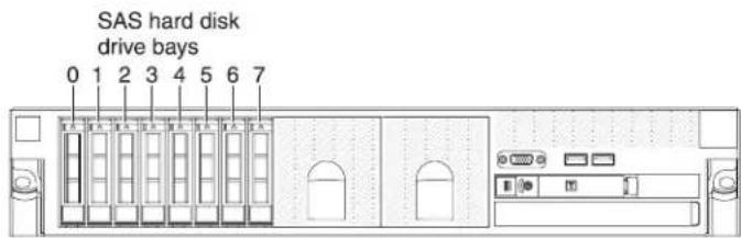
You can purchase an optional kit to install the tape drive.

You can purchase an optional kit to install the eight additional SAS hard disk drive bays.

The SAS ID for each bay is printed on the server front, above each bay.
If firmware and documentation updates are available, you can download them from the IBM Web site. The server might have features that are not described in the documentation that comes with the server, and the documentation might be updated occasionally to include information about those features, or technical updates might be available to provide additional information that is not included in the server documentation. To check for updates, complete the following steps.
Note: Changes are made periodically to the IBM Web site. Procedures for locating firmware and documentation might vary slightly from what is described in this document.
-
Go to http://www.ibm.com/systems/support/.
-
Under Product support, click System x.
-
Under Popular links, click Software and device drivers for firmware updates, or click Publications lookup for documentation updates.
Record information about the server in the following table.
Product name IBM System x3650 M3 server
Machine type 4255, 7945, or 7949
Model number
Serial number
The model number and serial number are on the ID label on the bezel, as shown in the following illustration.
Note: The illustrations in this document might differ slightly from your hardware.

You can download an IBM ServerGuide Setup and Installation CD to help you configure the hardware, install device drivers, and install the operating system. For more information, see "Using the ServerGuide Setup and Installation CD" on page 150
For a list of supported optional devices for the server, see http://www.ibm.com/servers/eserver/serverproven/compat/us.
See the Rack Installation Instructions document on the IBM Documentation CD for complete rack installation and removal instructions.
The IBM Documentation CD
The IBM Documentation CD contains documentation for your server in Portable Document Format (PDF) and includes the IBM Documentation Browser to help you find information quickly.
Hardware and software requirements
The IBM Documentation CD requires the following minimum hardware and software:
- Microsoft Windows XP, Windows 2000, or Red Hat Linux
• 100 MHz microprocessor
• 32 MB of RAM - Adobe Acrobat Reader 3.0 (or later) or xpdf, which comes with Linux operating systems
Using the Documentation Browser
Use the Documentation Browser to browse the contents of the CD, read brief descriptions of the documents, and view documents, using Adobe Acrobat Reader or xpdf. The Documentation Browser automatically detects the regional settings in use in your server and displays the documents in the language for that region (if available). If a document is not available in the language for that region, the English-language version is displayed.
Use one of the following procedures to start the Documentation Browser:
- If Autostart is enabled, insert the CD into the CD or DVD drive. The Documentation Browser starts automatically.
- If Autostart is disabled or is not enabled for all users, use one of the following procedures:
- If you are using a Windows operating system, insert the CD into the CD or DVD drive and click Start --> Run. In the Open field, type
e:\win32.bat
where e is the drive letter of the CD or DVD drive, and click OK.
- If you are using Red Hat Linux, insert the CD into the CD or DVD drive; then, run the following command from the /mnt/cdrom directory:
shrunlinux.sh
Select your server from the Product menu. The Available Topics list displays all the documents for your server. Some documents might be in folders. A plus sign (+) indicates each folder or document that has additional documents under it. Click the plus sign to display the additional documents.
When you select a document, a description of the document appears under Topic Description. To select more than one document, press and hold the Ctrl key while you select the documents. Click View Book to view the selected document or documents in Acrobat Reader or xpdf. If you selected more than one document, all the selected documents are opened in Acrobat Reader or xpdf.
To search all the documents, type a word or word string in the Search field and click Search. The documents in which the word or word string appears are listed in order of the most occurrences. Click a document to view it, and press Crtl+F to use the Acrobat search function, or press Alt+F to use the xpdf search function within the document.
Click Help for detailed information about using the Documentation Browser.
Related documentation
This Installation and User's Guide contains general information about the server, including how to set up the server, how to install supported optional devices, and how to configure the server. The following documentation also comes with the server:
• Warranty Information
This printed document contains information about the terms of the warranty.
- Safety Information
This document is in PDF on the IBM Documentation CD. It contains translated caution and danger statements. Each caution and danger statement that appears in the documentation has a number that you can use to locate the corresponding statement in your language in the Safety Information document.
- Rack Installation Instructions
This printed document contains instructions for installing the server in a rack.
• Problem Determination and Service Guide
This document is in PDF on the IBM Documentation CD. It contains information to help you solve problems yourself, and it contains information for service technicians.
• Environmental Notices and User Guide
This document is in PDF on the IBM Documentation CD. It contains translated environmental notices.
• IBM License Agreement for Machine Code
This document is in PDF on the IBM Documentation CD. It provides translated versions of the IBM License Agreement for Machine Code for your product.
• Licenses and Attributions Documents
This document is in PDF. It contains information about the open-source notices.
Depending on the server model, additional documentation might be included on the IBM Documentation CD.
The System x ^ and xSeries ^ Tools Center is an online information center that contains information about tools for updating, managing, and deploying firmware, device drivers, and operating systems. The System x and xSeries Tools Center is at http://publib.boulder.ibm.com/infocenter/toolsctr/v1r0/index.jsp.
The server might have features that are not described in the documentation that comes with the server. The documentation might be updated occasionally to include information about those features, or technical updates might be available to provide additional information that is not included in the server documentation. These updates are available from the IBM Web site. To check for updated documentation and technical updates, complete the following steps.
Note: Changes are made periodically to the IBM Web site. The actual procedure might vary slightly from what is described in this document.
- Go to http://www.ibm.com/systems/support/.
- Under Product support, click System x.
- Under Popular links, click Publications lookup.
- From the Product family menu, select System x3650 M3 and click Continue.
Notices and statements in this document
The caution and danger statements in this document are also in the multilingual Safety Information document, which is on the Documentation CD. Each statement is numbered for reference to the corresponding statement in your language in the Safety Information document.
The following notices and statements are used in this document:
- Note: These notices provide important tips, guidance, or advice.
- Important: These notices provide information or advice that might help you avoid inconvenient or problem situations.
- Attention: These notices indicate potential damage to programs, devices, or data. An attention notice is placed just before the instruction or situation in which damage might occur.
- Caution: These statements indicate situations that can be potentially hazardous to you. A caution statement is placed just before the description of a potentially hazardous procedure step or situation.
- Danger: These statements indicate situations that can be potentially lethal or extremely hazardous to you. A danger statement is placed just before the description of a potentially lethal or extremely hazardous procedure step or situation.
Features and specifications
The following information is a summary of the features and specifications of the server. Depending on the model, some features might not be available, or some specifications might not apply.
Racks are marked in vertical increments of 4.45 cm (1.75 inches). Each increment is referred to as a unit, or "U." A 1-U-high device is 1.75 inches tall.
Notes:
- Power consumption and heat output vary depending on the number and type of optional features that are installed and the power-management optional features that are in use.
- The sound levels were measured in controlled acoustical environments according to the procedures specified by the American National Standards Institute (ANSI) S12.10 and ISO 7779 and are reported in accordance with ISO 9296. Actual sound-pressure levels in a given location might exceed the average values stated because of room reflections and other nearby noise sources. The declared sound-power levels indicate an upper limit, below which a large number of computers will operate.
Table 1. Features and specifications
| Microprocessor:Supports up to two Intel Xeon ^TM multi-core microprocessors (one installed)Level-3 cacheQuickPath Interconnect (QPI) links speed up to 6.4 GT per secondNote:Do not install an Intel Xeon ^TM 5500 series microprocessor and an Xeon ^TM 5600 series microprocessor in the same server.Use the Setup utility to determine the type and speed of the microprocessors.For a list of supported microprocessors, see http://www.ibm.com/servers/eserver,serverproven/compat/us Memory:Minimum: 2 GBMaximum: 288 GB-48 GB using unbuffered DIMMs (UDIMMs)-288 GB using registered DIMMs (RDIMMs)Type: PC3-10600R-999, 800, 1067, and 1333 MHz, ECC, DDR3 registered or unbuffered SDRAM DIMMsSlots: 18 dual inlineSupports (depending on the model):-2 GB and 4 GB unbuffered DIMMs-2 GB, 4 GB, 8 GB, and 16 GB registered DIMMsSATA optical drives (optional):DVD-ROMMulti-burnerHard disk drive expansion bays (depending on the model):Eight 2.5-inch SAS hot-swap bays for hard disk drive bays with option to add eight more 2.5-inch SAS hot-swap hard disk drive baysFour 2.5-inch simple-swap, solid state SATA hard disk drive baysPCI expansion slots:Two PCI Express riser cards with two PCI Express x8 slots (x8 lanes) each, standardSupport for the following optional riser cards:- Two 133 MHz/64-bit PCI-X 1.0a slots-One PCI Express x16 slot (x16 lanes) | Size (2U):Height: 85.2 mm (3.346 in.)Depth: EIA flange to rear - 698 mm (27.480 in.), Overall - 729 mm (28.701 in.)Width: With top cover - 443.6 mm (17.465 in.), With front bezel - 482.0 mm (18.976 in.)Weight: approximately 21.09 kg (46.5 lb) to 25 kg (55 lb) depending upon configurationIntegrated functions:Integrated management module (IMM), which provides service processor control and monitoring functions, video controller, and (when the optional virtual media key is installed) remote keyboard, video, mouse, and remote hard disk drive capabilitiesDedicated or shared management network connectionsSerial over LAN (SOL) and serial redirection over Telnet or Secure Shell (SSH)One systems-management RJ-45 for connection to a dedicated systems-management networkSupport for remote management presence through an optional virtual media keyBroadcom BCM5709 Gb Ethernet controller with TCP/IP Offload Engine (TOE) and Wake on LAN supportFour Ethernet ports (two on system board and two additional ports when the optional IBM Dual-Port 1 Gb Ethernet Daughter Card is installed)One serial port, shared with the integrated management module (IMM)Four Universal Serial Bus (USB) ports (two on front, two on rear of server), v2.0 supporting v1.1, plus one or more dedicated internal USB ports on the SAS riser-cardTwo video ports (one on front and one on rear of server)One SATA tape connector, one USB tape connector, and one tape power connector on SAS riser-card (some models)Support for hypervisor function through an optional USB flash device on the SAS riser-card (not available on simple-swap models)Note:In messages and documentation, the term service processor refers to the integrated management module (IMM). | Video controller (integrated into IMM):Matrox G200eV (two analog ports - one front and one rear that can be connected at the same time)Note:The maximum video resolution is 1600 x 1200 at 75 Hz.- SVGA compatible video controller- DDR2 250 MHz SDRAM video memory controller-Avocent Digital Video Compression- 16 MB of video memory (not expandable)ServeRAID controller (depending on the model):A ServeRAID-BR10il v2 SAS/SATA adapter that provides RAID levels 0, 1, and 1E (comes standard on some hot-swap models).An optional ServeRAID-BR10il SAS/SATA adapter that provides RAID levels 0, 1, and 1E can be ordered.An optional ServeRAID-MR10i SAS/SATA adapter that provides RAID levels 0, 1, 5, 6, 10, 50, and 60 can be ordered.An optional ServeRAID-M1015 SAS/SATA adapter that provides RAID levels 0, 1, and 10 with optional RAID 5/50 and SED (Self Encrypting Drive) upgrade.An optional ServeRAID-M5014 SAS/SATA adapter that provides RAID levels 0, 1, 5, 10 and 50 with optional battery and RAID 6/60 and SED upgrade.An optional ServeRAID-M5015 SAS/SATA adapter with battery that provides RAID levels 0, 1, 5, 10, and 50 with optional RAID 6/60 and SED upgradeNotes:RAID is supported in hot-swap models only.The ServeRAID controllers are installed in a PCI Express x8 mechanical slot (x4 electrical); however, the controllers run at x4 bandwidth. |
| Electrical input with hot-swap ac power supplies:• Sine-wave input (47 - 63 Hz) required• Input voltage range automatically selected• Input voltage low range:- Minimum: 100 V ac- Maximum: 127 V ac• Input voltage high range:- Minimum: 200 V ac- Maximum: 240 V ac• Input kilovolt-amperes (kVA) approximately:- Minimum: 0.090 kVA- Maximum: 0.700 kVA | Environment:• Air temperature:- Server on: 10°C to 35°C (50.0°F to 95.0°F); altitude: 0 to 914.4 m (3000 ft). Decrease system temperature by 1°C for every 1000-foot increase in altitude.- Server off: 5°C to 45°C (41.0°F to 113.0°F); maximum altitude: 3048 m (10000 ft)- Shipment: -40°C to +60°C (-40°F to 140°F); maximum altitude: 3048 m (10000 ft)• Humidity:- Server on: 20% to 80%; maximum dew point: 21°C; maximum rate of change 5°C per hour.- Server off: 8% to 80%; maximum dew point: 27°C- Shipment: 5% to 100%• Particulate contamination:Attention: Airborne particulates and reactive gases acting alone or in combination with other environmental factors such as humidity or temperature might pose a risk to the server. For information about the limits for particulates and gases, see"Particulate contamination" on page165 | Hot-swap fans:Three - provide redundant cooling.Power supply:• Up to two hot-swap power supplies for redundancy support- 460-watt ac- 675-watt ac- 675-watt high-efficiency ac- 675-watt dcNote: You cannot mix 460-watt and 675-watt power supplies, or high-efficiency and non-high-efficiency power supplies, or ac and dc power supplies in the server.Acoustical noise emissions:• Declared sound power, idle: 6.3 bel• Declared sound power, operating: 6.5 belHeat output:Approximate heat output:• Minimum configuration: 662 Btu per hour (194 watts)• Maximum configuration: 2302 Btu per hour (675 watts) |
What your server offers
The server uses the following features and technologies:
• UEFI-compliant server firmware
IBM System x Server Firmware offers several features, including Unified Extensible Firmware Interface (UEFI) 2.1 compliance, Active Energy Manager technology, enhanced RAS capabilities, and BIOS compatibility support. UEFI replaces the basic input/output system (BIOS) and defines a standard interface between the operating system, platform firmware, and external devices. UEFI-compliant System x servers are capable of booting UEFI-compliant operating systems, BIOS-based operating systems, and BIOS-based adapters as well as UEFI-compliant adapters.
Note: The server does not support DOS.
- Integrated management module
The integrated management module (IMM) combines service processor functions, video controller, and (when an optional virtual media key is installed) remote presence function in a single chip. The IMM provides advanced service-processor control, monitoring, and alerting function. If an environmental condition exceeds a threshold or if a system component fails, the IMM lights LEDs to help you diagnose the problem, records the error in the event log, and alerts you to the problem. Optionally, the IMM also provides a virtual presence capability for remote server management capabilities. The IMM provides remote server management through industry-standard interfaces:
– Intelligent Platform Management Interface (IPMI) version 2.0
– Simple Network Management Protocol (SNMP) version 3
– Common Information Model (CIM)
- Web browser
- Remote presence capability and blue-screen capture
The optional virtual media key is required to enable the remote presence and blue-screen capture features. The remote presence feature provides the following functions:
- Remotely viewing video with graphics resolutions up to 1600 x 1200 at 75 Hz, regardless of the system state
- Remotely accessing the server, using the keyboard and mouse from a remote client
- Mapping the CD or DVD drive, diskette drive, and USB flash drive on a remote client, and mapping ISO and diskette image files as virtual drives that are available for use by the server
- Uploading a diskette image to the IMM memory and mapping it to the server as a virtual drive
The blue-screen capture feature captures the video display contents before the IMM restarts the server when the IMM detects an operating-system hang condition. A system administrator can use the blue-screen capture to assist in determining the cause of the hang condition.
• IBM Dynamic System Analysis Preboot diagnostics programs
The Dynamic System Analysis (DSA) Preboot diagnostics programs are stored on the integrated USB memory. It collects and analyzes system information to aid in diagnosing server problems. The diagnostic programs collect the following information about the server:
– System configuration
– Network interfaces and settings
- Installed hardware
– Light path diagnostics status
– Service processor status and configuration
– Vital product data, firmware, and UEFI (formerly BIOS) configuration
– Hard disk drive health
- RAID controller configuration
– Event logs for ServeRAID controllers and service processors
The diagnostic programs create a merged log that includes events from all collected logs. The information is collected into a file that you can send to IBM service and support. Additionally, you can view the information locally through a generated text report file. You can also copy the log to a removable media and view the log from a Web browser.
For additional information about DSA Preboot diagnostics, see the Problem Determination and Service Guide on the IBM Documentation CD
• IBM Systems Director
IBM Systems Director is a workgroup-hardware-management tool that you can use to centrally manage System x and xSeries servers. For more information, see the IBM Systems Director documentation on the IBM Systems Director CD.
• Active Energy Manager
The Active Energy Manager solution is an IBM Systems Director extension that measures and reports server power consumption as it occurs. This enables you to monitor power consumption in correlation to specific software application
programs and hardware configurations. You can obtain the measurement values through the systems-management interface and view them, using IBM Systems Director. For more information, see the IBM Director documentation on the IBM Systems Director CD, or see http://www.ibm.com/systems/management/director/extensions/actengmrg.htm.
• IBM X-Architecture technology
IBM X-Architecture technology combines proven, innovative IBM designs to make your Intel-processor-based server powerful, scalable, and reliable. For more information, see http://www.ibm.com/servers/eserver/xseries/xarchitecture/enterprise/index.html.
- Active ^TM Memory
The Active Memory ^™ feature improves the reliability of memory through memory mirroring. Memory mirroring stores data in two pairs of DIMMs simultaneously.
– Large system-memory capacity
The memory bus supports up to 288 GB of system memory when registered DIMMs are installed. The server supports up to 48 GB if unbuffered DIMMs are installed. The memory controller supports error correcting code (ECC) for up to 18 industry-standard PC3-10600R-999, 800, 1067, and 1333 MHz, DDR3 (third-generation double-data-rate), synchronous dynamic random access memory (SDRAM) dual inline memory modules (DIMMs).
• IBM ServerGuide Setup and Installation CD
The ServerGuide Setup and Installation CD, which you can download from the Web, provides programs to help you set up the server and install a Windows operating system. The ServerGuide program detects installed optional hardware devices and provides the correct configuration programs and device drivers. For more information about the ServerGuide Setup and Installation CD, see "Using the ServerGuide Setup and Installation CD" on page 150.
• Integrated network support
The server comes with two integrated Broadcom Gigabit Ethernet controllers, which support connection to a 10 Mbps, 100 Mbps, or 1000 Mbps network. For more information, see "Configuring the Gigabit Ethernet controller" on page 156.
• Large data-storage and hot-swap capability
The server supports up to eight or sixteen 2.5-inch hot-swap hard disk drives in the hot-swap bays (depending on the model and optional devices installed). With the hot-swap feature, you can add, remove, or replace hard disk drives without turning off the server.
• Light path diagnostics
Light path diagnostics provides LEDs to help you diagnose problems. For more information, see the section about light path diagnostics in the Problem Determination and Service Guide.
- PCI adapter capabilities
The server supports up to four PCI interface slots. For more information, see "Installing a PCI adapter" on page 53.
- Memory mirroring
Memory mirroring improves the availability of memory by writing information to the main memory and redundant locations in a mirrored pair of DIMMs.
- Redundant connection
The addition of the optional Ethernet daughter card provides failover capability to a redundant Ethernet connection with the applicable application installed. If a problem occurs with the primary Ethernet connection and the optional Ethernet
daughter card is installed on the server, all Ethernet traffic that is associated with the primary connection is automatically switched to the optional redundant Ethernet daughter card connection. If the applicable device drivers are installed, this switching occurs without data loss and without user intervention.
- Redundant cooling and optional power capabilities
The server supports three hot-swap fans, which provide redundant cooling. Redundant cooling enables continued operation if one of the fans fails. The server supports a maximum of two 675-watt or 460-watt hot-swap power supplies, which provide redundancy and hot-swap capability for a typical configuration. The server comes with one 675-watt or 460-watt hot-swap power supply. You can order the second optional power supply for power redundancy. If the maximum load on the server is less than 675-watts (or 460-watt, depending on what kind of power supply you use) and a problem occurs with one of the power supplies, the other power supply can meet the power requirements.
Note: If the maximum load on the server is greater than 675-watts (or 460-watt, depending on what kind of power supply you use) and a problem occurs with one of the power supplies, Active Energy Manager can act to minimize the load somewhat so that the server can function with the remaining power supply.
- ServeRAID support
The server supports an internal ServeRAID SAS controller, which is required for you to use the hot-swap hard disk drives and to create redundant array of independent disks (RAID) configurations.
- Systems-management capabilities
The server contains an integrated management module (IMM) which enables you to manage the functions of the server locally and remotely. The addition of the optional IBM Virtual Media Key provides remote presence and blue-screen capture capability. The IMM also provides system monitoring, event recording, and dial-out alert capability.
• TCP/IP offload engine (TOE) support
The Ethernet controllers in the server support TOE, which is a technology that offloads the TCP/IP flow from the microprocessors and I/O subsystem to increase the speed of the TCP/IP flow. When an operating system that supports TOE is running on the server and TOE is enabled, the server supports TOE operation. See the operating-system documentation for information about enabling TOE.
Note: As of the date of this document, the Linux operating system does not support TOE.
Reliability, availability, and serviceability features
Three important computer design features are reliability, availability, and serviceability (RAS). The RAS features help to ensure the integrity of the data that is stored in the server, the availability of the server when you need it, and the ease with which you can diagnose and repair problems.
The server has the following RAS features:
• 3-year parts and 3-year labor limited warranty for machine types 7945 and 7949 and 4-year parts and 4-year labor limited warranty for machine type 4255
• Automatic error retry and recovery
• Automatic restart after a power failure
• Built-in monitoring for fan, power, temperature, voltage, and power-supply redundancy
- Cable-presence detection on most connectors
• Chipkill memory protection
- Dual redundant UEFI server firmware images
- Error codes and messages
- Error correcting code (ECC) L2 cache and system memory
• Hot-swap cooling fans with speed-sensing capability
• Hot-swap hard disk drives
• Information and light path diagnostics LED panels
- Integrated management module (service processor)
- Memory mirroring
- Menu-driven setup, system configuration, and redundant array of independent disks (RAID) configuration programs
- Parity checking or CRC checking on the serially-attached SCSI (SAS) bus and PCI buses
- Power management: compliance with Advanced Configuration and Power Interface (ACPI)
• Power-on self-test (POST)
- Predictive Failure Analysis (PFA) alerts on memory, SAS/SATA hard disk drives, fans, and power supplies
- Redundant Ethernet capabilities with failover support
- Redundant hot-swap power supplies
- Remind button to temporarily turn off the system-error LED
- Remote system problem-determination support
- Standby voltage for systems-management features and monitoring
- Startup (boot) from LAN through Preboot Execution Environment (PXE) boot agent utility or Dynamic Host Configuration Protocol/Boot Protocol (DHCP/BOOTP)
- System auto-configuring from the configuration menu
- System error logging (POST and service processor)
- Systems-management monitoring through the Inter-Integrated Circuit (I ^2 C) bus
- Upgradeable POST, UEFI, diagnostics, service processor microcode, and read-only memory (ROM) resident code, locally or over the LAN
- Vital product data (VPD) on microprocessors, system board, power supplies, and SAS (hot-swap-drive) backplane
- Wake on LAN capability
IBM Systems Director
IBM Systems Director is a platform-management foundation that streamlines the way you manage physical and virtual systems in a heterogeneous environment. By using industry standards, IBM Systems Director supports multiple operating systems and virtualization technologies in IBM and non-IBM x86 platforms.
Through a single user interface, IBM Systems Director provides consistent views for viewing managed systems, determining how these systems relate to one another, and identifying their statuses, helping to correlate technical resources with business needs. A set of common tasks that are included with IBM Systems Director provides many of the core capabilities that are required for basic management, which means instant out-of-the-box business value. These common tasks include discovery, inventory, configuration, system health, monitoring, updates, event notification, and automation for managed systems.
The IBM Systems Director Web and command-line interfaces provide a consistent interface that is focused on driving these common tasks and capabilities:
- Discovering, navigating, and visualizing systems on the network with the detailed inventory and relationships to the other network resources
- Notifying users of problems that occur on systems and the ability to isolate the sources of the problems
- Notifying users when systems need updates and distributing and installing updates on a schedule
- Analyzing real-time data for systems and setting critical thresholds that notify the administrator of emerging problems
- Configuring settings of a single system and creating a configuration plan that can apply those setting to multiple systems
- Updating installed plug-ins to add new features and functions to the base capabilities
- Managing the life cycles of virtual resources
For more information about IBM Systems Director, see the documentation on the IBM Systems Director DVD that comes with the server and the IBM xSeries Systems Management Web page at http://www.ibm.com/systems/management/ which presents an overview of IBM Systems Management and IBM Systems Director.
The UpdateXpress System Pack Installer
The UpdateXpress System Pack Installer detects supported and installed device drivers and firmware in the server and installs available updates. For additional information and to download the Update Xpress System Pack Installer, go to the System x and BladeCenter Tools Center at http://publib.boulder.ibm.com/infocenter/toolsctr/v1r0/index.jsp and click UpdateXpress System Pack Installer.
Server controls, LEDs, and power
This section describes the controls and light-emitting diodes (LEDs) and how to turn the server on and off.
Front view
The following illustration shows the controls, connectors, and hard disk drive bays on the front of the server.
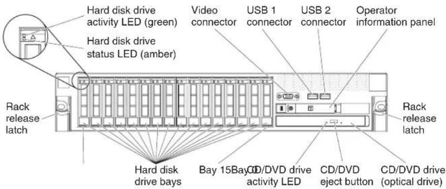
Hard disk drive activity LED: Each hard disk drive has an activity LED. When this LED is flashing, it indicates that the drive is in use.
Hard disk drive status LED: Each hard disk drive has a status LED. When this LED is lit, it indicates that the drive has failed. When this LED is flashing slowly (one flash per second), it indicates that the drive is being rebuilt as part of a RAID configuration. When the LED is flashing rapidly (three flashes per second), it indicates that the controller is identifying the drive.
Video connector: Connect a monitor to this connector. The video connectors on the front and rear of the server can be used simultaneously.
USB connectors: Connect a USB device, such as USB mouse, keyboard, or other USB device, to either of these connectors.
Operator information panel: This panel contains controls, light-emitting diodes (LEDs), and connectors. For information about the controls and LEDs on the operator information panel, see "Operator information panel" on page 15.
Rack release latches: Press these latches to release the server from the rack.
Optional CD/DVD-eject button: Press this button to release a CD or DVD from the CD-RW/DVD drive.
Optional CD/DVD drive activity LED: When this LED is lit, it indicates that the CD-RW/DVD drive is in use.
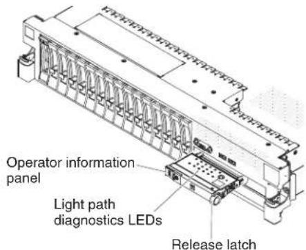
Operator information panel
The following illustration shows the controls and LEDs on the operator information panel.

The following controls and LEDs are on the operator information panel:
- Power-control button and power-on LED: Press this button to turn the server on and off manually or to wake the server from a reduced-power state. The states of the power-on LED are as follows:
Off: AC power is not present, or the power supply or the LED itself has failed.
Flashing rapidly (4 times per second): The server is turned off and is not ready to be turned on. The power-control button is disabled. This will last approximately 20 to 40 seconds.
Note: Approximately 40 seconds after the server is connected to ac power, the power-control button becomes active.
Flashing slowly (once per second): The server is turned off and is ready to be turned on. You can press the power-control button to turn on the server.
Lit: The server is turned on.
Fading on and off: The server is in a reduced-power state. To wake the server, press the power-control button or use the IMM Web interface. For information about logging on to the IMM Web interface, see “logging on to the Web interface” on page 155.
- Ethernet icon LED: This LED lights the Ethernet icon.
- Ethernet activity LEDs: When any of these LEDs is lit, it indicates that the server is transmitting to or receiving signals from the Ethernet LAN that is connected to the Ethernet port that corresponds to that LED.
- Information LED: When this LED is lit, it indicates that a noncritical event has occurred. An LED on the light path diagnostics panel is also lit to help isolate the error.
- System-error LED: When this LED is lit, it indicates that a system error has occurred. An LED on the light path diagnostics panel is also lit to help isolate the error.
- Release latch: Slide this latch to the left to access the light path diagnostics panel, which is behind the operator information panel.
- Locator button and locator LED: Use this LED to visually locate the server among other servers. Press this button to turn on or turn off this LED locally. You can use IBM Systems Director to light this LED remotely.
Light path diagnostics panel
The light path diagnostics panel is on the top of the operator information panel.
To access the light path diagnostics panel, slide the blue release button on the operator information panel to the left. Pull forward on the operator information panel until the hinge of the panel is free of the server chassis. Then pull down on the operator information panel, so that you can view the light path diagnostics panel information.
The following illustration shows the controls and LEDs on the light path diagnostics panel.
Notes:
-
Do not run the server for an extended period of time while the light path diagnostics panel is pulled out of the server.
-
Light path diagnostics LEDs remain lit only while the server is connected to power.

- Remind button: This button places the system-error LED on the front panel into Remind mode. In Remind mode, the system-error LED flashes once every 2 seconds until the problem is corrected, the server is restarted, or a new problem occurs.
By placing the system-error LED indicator in Remind mode, you acknowledge that you are aware of the last failure but will not take immediate action to correct the problem. The remind function is controlled by the IMM.
- NMI button: Press this button to force a nonmaskable interrupt to the microprocessor, if directed to do so by IBM service and support.
- Reset button: Press this button to reset the server and run the power-on self-test (POST). You might have to use a pen or the end of a straightened paper clip to press the button. The reset button is in the lower-right corner of the light path diagnostics panel.
For more information about light path diagnostics, see the Problem Determination and Service Guide on the IBM Documentation CD.
Rear view
The following illustration shows the connectors on the rear of the server.
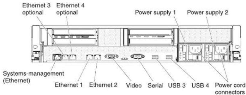
Ethernet connectors: Use either of these connectors to connect the server to a network. When you use the Ethernet 1 connector, the network can be shared with the IMM through a single network cable.
Power-cord connector: Connect the power cord to this connector.
USB connectors: Connect a USB device, such as USB mouse, keyboard, or other USB device, to any of these connectors.
Serial connector: Connect a 9-pin serial device to this connector. The serial port is shared with the integrated management module (IMM). The IMM can take control of the shared serial port to perform text console redirection and to redirect serial traffic, using Serial over LAN (SOL).
Video connector: Connect a monitor to this connector. The video connectors on the front and rear of the server can be used simultaneously.
Note: The maximum video resolution is 1600 x 1200 at 75 Hz.
Systems-management Ethernet connector: Use this connector to connect the server to a network for systems-management information control. This connector is used only by the IMM.
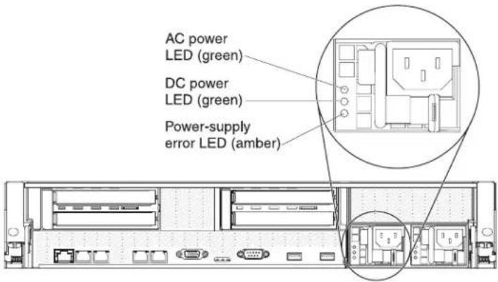
The following illustration shows the LEDs on the rear of the server.

Ethernet activity LEDs: When these LEDs are lit, they indicate that the server is transmitting to or receiving signals from the Ethernet LAN that is connected to the Ethernet port.
Ethernet link LEDs: When these LEDs are lit, they indicate that there is an active link connection on the 10BASE-T, 100BASE-TX, or 1000BASE-TX interface for the Ethernet port.
AC power LED: Each hot-swap power supply has an ac power LED and a dc power LED. When the ac power LED is lit, it indicates that sufficient power is coming into the power supply through the power cord. During typical operation, both the ac and dc power LEDs are lit. For any other combination of LEDs, see the Problem Determination and Service Guide on the IBM Documentation CD.
IN OK power LED: Each hot-swap dc power supply has an IN OK power LED and an OUT OK power LED. When the IN OK power LED is lit, it indicates that sufficient power is coming into the power supply through the power cord. During typical operation, both the IN OK and OUT OK power LEDs are lit.
DC power LED: Each hot-swap power supply has a dc power LED and an ac power LED. When the dc power LED is lit, it indicates that the power supply is supplying adequate dc power to the system. During typical operation, both the ac and dc power LEDs are lit. For any other combination of LEDs, see the Problem Determination and Service Guide on the IBM Documentation CD.
OUT OK power LED: Each hot-swap dc power supply has an IN OK power LED and an OUT OK power LED. When the OUT OK power LED is lit, it indicates that the power supply is supplying adequate dc power to the system. During typical operation, both the IN OK and OUT OK power LEDs are lit.
Power-supply error LED: When the power-supply error LED is lit, it indicates that the power supply has failed.
Note: Power supply 1 is the default/primary power supply. If power supply 1 fails, you must replace the power supply immediately.
System-error LED: When this LED is lit, it indicates that a system error has occurred. An LED on the light path diagnostics panel is also lit to help isolate the error. This LED is the same as the system-error LED on the front of the server.
Locator LED: Use this LED to visually locate the server among other servers. You can use IBM Systems Director to light this LED remotely. This LED is the same as the system-locator LED on the front of the server.
Power-on LED: Press this button to turn the server on and off manually or to wake the server from a reduced-power state. The states of the power-on LED are as follows:
Off: AC power is not present, or the power supply or the LED itself has failed.
Flashing rapidly (4 times per second): The server is turned off and is not ready to be turned on. The power-control button is disabled. This will last approximately 20 to 40 seconds.
Note: Approximately 40 seconds after the server is connected to ac power, the power-control button becomes active.
Flashing slowly (once per second): The server is turned off and is ready to be turned on. You can press the power-control button to turn on the server.
Lit: The server is turned on.
Fading on and off: The server is in a reduced-power state. To wake the server, press the power-control button or use the IMM Web interface. For information about logging on to the IMM Web interface, see "Logging on to the Web Interface" on page 155.
Power-supply LEDs
The following illustration shows the power-supply LEDs on the rear of the server. For more information about solving power-supply problems, see the Problem Determination and Service Guide.
The following table describes the problems that are indicated by various combinations of the power-supply LEDs and the power-on LED on the operator information panel and suggested actions to correct the detected problems.
Table 2. Power-supply LEDs
| AC power-supply LEDs | Description Action | NotesAC DC Error | |||
| Off Off | Off No ac | power to | the server or a problem with the ac power source | 1. Check the ac power to the server.2. Make sure that the power cord is connected to a functioning power source.3. Turn the server off and then turn the server back on.4. If the problem remains, replace the power supply. | This is a normal condition when no ac power is present. |
| Off Off | On No ac | power to | the server or a problem with the ac power source and the power supply had detected an internal problem | 1. Replace the power supply.2. Make sure that the power cord is connected to a functioning power source. | This happens only when a second power supply is providing power to the server. |
| Off On | Off Faulty | power | supply | Replace the power supply. | |
| Off On | On Faulty | power | supply | Replace the power supply. | |
| On Off | Off Power | supply not | fully seated, faulty system board, or faulty power supply | 1. (Trained service technician only) Reseat the power supply.2. If a power channel error LED on the system board is not lit, replace the power-supply (see the documentation that comes with the power supply for instructions).3. If a power channel error LED on the system board is lit, (trained service technician only) replace the system board. | Typically indicates that a power supply is not fully seated. |
| On Off | or Flashing | On Faulty | power supply | Replace the power supply. | |
| On On | Off Normal | operation | |||
| On On | On Power | supply is | faulty but still operational | Replace the power supply. | |
The following table describes the problems that are indicated by various combinations of the power-supply LEDs on a dc power supply and suggested actions to correct the detected problems.
| DC power-supply LEDs | Description Action | NotesIN OK OUT OK Error (!) | |||
| On On | Off Normal operation | ||||
| Off Off | Off No dc power to the | server or a problem with the dc power source. | 1. Check the dc power to the server.2. Make sure that the power cord is connected to a functioning power source.3. Restart the server. If the error remains, check the power-supply LEDs.4. Replace the power-supply. | This is a normal condition when no dc power is present. | |
| Off Off | On No dc power to the | server or a problem with the dc power source and the power-supply had detected an internal problem. | Make sure that the power cord is connected to a functioning power source.Replace the power supply (see the documentation that comes with the power supply for instructions). | This happens only when a second power supply is providing power to the server. | |
| Off On | Off Faulty | power-supply | Replace the power supply. | ||
| Off On | On Faulty | power-supply | Replace the power supply. | ||
| On Off | Off Power-supply not | fully seated, faulty system board, or faulty power-supply | (Trained service technician only) Reseat the power supply.If a power channel error LED on the system board is not lit, replace the power-supply (see the documentation that comes with the power supply for instructions).If a power channel error LED on the system board is lit, (trained service technician only) replace the system board. | Typically indicates a power-supply is not fully seated. | |
| On Off | On Faulty | power-supply | Replace the power supply. | ||
| On On | On Power-supply is | faulty but still operational | Replace the power supply. | ||
Server power features
When the server is connected to a power source but is not turned on, the operating system does not run, and all core logic except for the integrated management module (IMM) is shut down; however, the server can respond to requests from the IMM, such as a remote request to turn on the server. The power-on LED flashes to indicate that the server is connected to power but is not turned on.
Turning on the server
Approximately 3 minutes after the server is connected to power, the power-control button becomes active, and one or more fans might start running to provide cooling while the server is connected to power. You can turn on the server and start the operating system by pressing the power-control button.
The server can also be turned on in any of the following ways:
- If a power failure occurs while the server is turned on, the server will restart automatically when power is restored.
- If your operating system supports the Wake on LAN feature, the Wake on LAN feature can turn on the server.
For 32-bit operating systems only: Some memory is reserved for various system resources and is unavailable to the operating system. The amount of memory that is reserved for system resources depends on the operating system, the configuration of the server, and the configured PCI options.
Turning off the server
When you turn off the server and leave it connected to power, the server can respond to requests from the IMM, such as a remote request to turn on the server. While the server remains connected to power, one or more fans might continue to run. To remove all power from the server, you must disconnect it from the power source.
Important: To view the error LEDs on the system board, leave the server connected to a power source.
Some operating systems require an orderly shutdown before you turn off the server. See your operating-system documentation for information about shutting down the operating system.
Statement 5:

CAUTION:
The power control button on the device and the power switch on the power supply do not turn off the electrical current supplied to the device. The device also might have more than one power cord. To remove all electrical current from the device, ensure that all power cords are disconnected from the power source.

The server can be turned off in any of the following ways:
- You can turn off the server from the operating system, if your operating system supports this feature. After an orderly shutdown of the operating system, the server will be turned off automatically.
-
You can press the power-control button to start an orderly shutdown of the operating system and turn off the server, if your operating system supports this feature.
-
If the operating system stops functioning, you can press and hold the power-control button for more than 4 seconds to turn off the server.
- The IMM can turn off the server as an automatic response to a critical system failure.
- You can turn off the server through a request from the IMM.
Chapter 2. Installing optional devices
This chapter provides detailed instructions for installing optional hardware devices in the server.
In addition to the instructions in this chapter for installing optional hardware devices, updating firmware and device drivers, and completing the installation, IBM Business Partners must also complete the steps in “Instructions for IBM Business Partners.”
Important: To help ensure that the devices that you install work correctly and do not introduce problems, observe the following precautions:
- Make sure that the server and the installed firmware levels support the devices that you are installing. If necessary, update the UEFI and IMM firmware and any other firmware that is stored on the system boards. For information about where firmware is stored in the server, see Chapter 6, "Configuration information and instructions," in the Problem Determination and Service Guide. For a list of supported optional devices for the server, see http://www.ibm.com/systems/info/x86servers/serverproven/compat/us/.
- Before you install optional hardware devices, make sure that the server is working correctly. Start the server and make sure that the operating system starts, if an operating system is installed, or that a 19990305 error code is displayed, indicating that an operating system was not found but the server is otherwise working correctly. If the server is not working correctly, see the Problem Determination and Service Guide for information about how to run diagnostics.
- Follow the installation procedures in this chapter and use the correct tools. Incorrectly installed devices can cause system failures because of damaged pins in sockets or connectors, loose cabling, or loose components.
- Use the best practices to apply current firmware and device-driver updates for the server and optional devices. To download the IBM System x Firmware Update Best Practices document, go to http://www.ibm.com/support/entry/portal/docdisplay?brand=50000020&Indocid=MIGR-5082923. Additional hints and tips are available from the following sites:
- IBM support: http://www.ibm.com/supportportal/
- System x configuration tools: http://www.ibm.com/systems/x/hardware/configtools.htm
Instructions for IBM Business Partners
In addition to the instructions in this chapter for installing optional hardware devices, updating firmware and device drivers, and completing the installation, IBM Business Partners must also complete the following steps:
- Before you configure a server for a customer, complete the Solution Assurance checklist at http://w3.ibm.com/support/assure/assur301.nst/webindex/sa294/
- After you have confirmed that the server starts correctly and recognizes the newly installed devices and that no error LEDs are lit, run the Dynamic System Analysis (DSA) stress tests. For information about using DSA, see the Problem Determination and Service Guide.
- Shut down and restart the server multiple times to ensure that the server is correctly configured and functions correctly with the newly installed devices.
-
Save the DSA log as a file and send it to IBM.
-
To ship the server, repackage it in the original undamaged packing material and observe IBM procedures for shipping.
Support information for IBM Business Partners is available at http://www.ibm.com/partnerworld.
Server components
The following illustrations show the major components in the server.
Note: The illustrations in this document might differ slightly from your hardware.

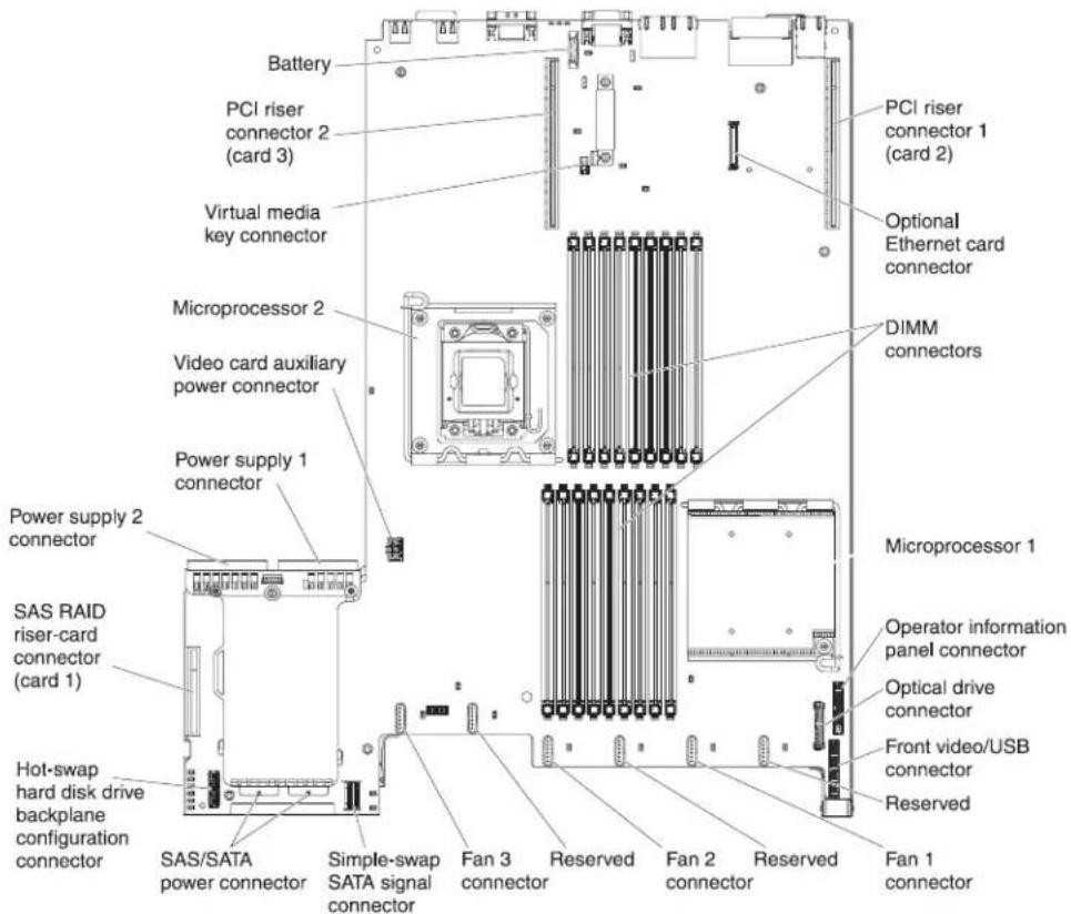
System-board internal connectors
The following illustration shows the internal connectors on the system board.
System-board external connectors
The following illustration shows the external input/output connectors on the system board.

System-board switches and jumpers
The following illustration shows the location and description of the switches and jumpers.
Note: If there is a clear protective sticker on the top of the switch blocks, you must remove and discard it to access the switches.
The default positions for the UEFI and the IMM recovery jumpers are pins 1 and 2.

The following table describes the jumpers on the system board.
Table 3. System board jumpers
| Jumper number | Jumper name Jumper setting |
| J29 UEFI boot recovery jumper | • Pins 1 and 2: Normal (default) Loads the primary server firmware ROM page.• Pins 2 and 3: Loads the secondary (backup) server firmware ROM page. |
| J147 IMM | recovery jumper• Pins 1 and 2: Normal (default) Loads the primary IMM firmware ROM page.• Pins 2 and 3: Loads the secondary (backup) IMM firmware ROM page. |
| Notes:1. If no jumper is present, the server responds as if the pins are set to 1 and 2.2. Changing the position of the UEFI boot recovery jumper from pins 1 and 2 to pins 2 and 3 before the server is turned on alters which flash ROM page is loaded. Do not change the jumper pin position after the server is turned on. This can cause an unpredictable problem. | |
The following illustration shows the jumper settings for switch blocks SW3 and SW4 on the system board.
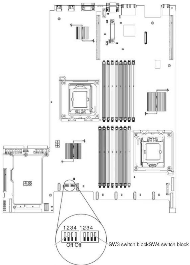
Table 4 on page 32 and Table 5 on page 32 describe the function of each switch on SW3 and SW4 switch blocks on the system board.
Table 4. System board switch block 3, switches 1 - 4
| Switch number | Default value | Switch description |
| 1 Off | Clear CMOS memory. | When this switch is toggled to On, it clears the data in CMOS memory. |
| 2 Off | Trusted Platform Module (TPM) physical presence. | Turning this switch to the on position indicates a physical presence to the TPM. |
| 3 Off | Reserved. | |
| 4 Off | Reserved. |
Table 5. System board switch block 4, switches 1 - 4
| Switch number | Default value | Switch description |
| 1 Off Power-on password override. Changing the position of this switch bypasses the power-on password check the next time the server is turned on and starts the Setup utility so that you can change or delete the power-on password. You do not have to move the switch back to the default position after the password is overridden.Changing the position of this switch does not affect the administrator password check if an administrator password is set.See "Passwords" on page 148 for additional information about the power-on password. | ||
| 2 Off Power-on override. When this switch is toggled to On and then to Off, you force a power-on which overrides the power-on and power-off button on the server and they become nonfunctional. | ||
| 3 Off Forced power permission overrides the IMM power-on checking process. (Trained service technician only) | ||
| 4 Off Reserved. | ||
Important:
-
Before you change any switch settings or move any jumpers, turn off the server; then, disconnect all power cords and external cables. (Review the information in "Safety" on page vii, Installation guidelines" on page 37, Handling static-sensitive devices" on page 39, and "Turning off the server" on page 22.)
-
Any system-board switch or jumper blocks that are not shown in the illustrations in this document are reserved.
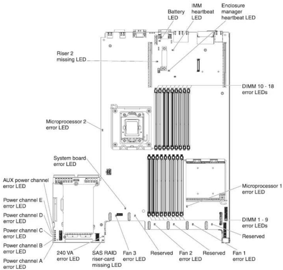
System-board LEDs
The following illustration shows the light-emitting diodes (LEDs) on the system board.
Note: Error LEDs remain lit only while the server is connected to power.
System pulse LEDs
The following LEDs are on the system board and monitor the system power-on and power-off sequencing and boot progress (see "System-board LEDs" for the location of these LEDs).
Table 6. System-pulse LEDs
| LED Description Action | ||
| Enclosure manager heartbeat | Indicates the status of power-on and power-off sequencing.When the server is connected to power, this LED flashes slowly to indicate that the enclosure manager is working correctly. | (Trained service technician only) If the server is connected to power and the LED is not flashing, replace the system board. |
| IMM heartbeat Indicates the status of the boot process of the IMM.When the server is connected to power this LED flashes quickly to indicate that the IMM code is loading. When the loading is complete, the LED stops flashing briefly and then flashes slowly to indicate that the IMM if fully operational and you can press the power-control button to start the server. | If the LED does not begin flashing within 30 seconds of when the server is connected to power, complete the following steps:1. (Trained service technician only) Use the IMM recovery jumper to recover the firmware (see Table 3 on page 30).2. (Trained service technician only) Replace the system board. | |
System-board optional device connectors
The following illustration shows the connectors on the system board for user-installable options.

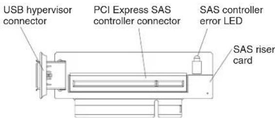
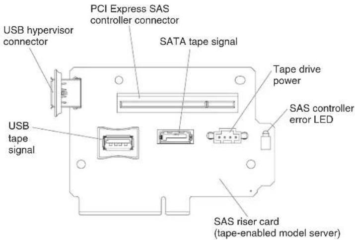
SAS riser-card connectors and LEDs
The following illustrations show the connectors and LEDs on the SAS riser-cards.
Note: Error LEDs remain lit only while the server is connected to power.
A 16-drive-capable model server contains the riser card that is shown in the following illustration.
A tape-enabled model server contains the riser card that is shown in the following illustration.
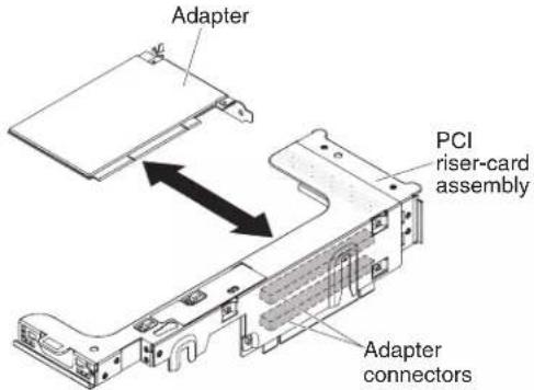
PCI riser-card adapter connectors
The following illustration shows the connectors on the PCI riser card for user-installable PCI adapters.
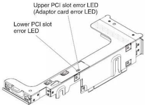
PCI riser-card assembly LEDs
The following illustration shows the light-emitting diodes (LEDs) on the PCI riser-card assembly.
Note: Error LEDs remain lit only while the server is connected to power.
Installation guidelines
Attention: Static electricity that is released to internal server components when the server is powered-on might cause the system to halt, which might result in the loss of data. To avoid this potential problem, always use an electrostatic-discharge wrist strap or other grounding system when removing or installing a hot-swap device.
Before you install optional devices, read the following information:
- Read the safety information that begins on page vi, the guidelines in "Working inside the server with the power on" on page 38, and "Handling static-sensitive devices" on page 39. This information will help you work safely.
-
When you install your new server, take the opportunity to download and apply the most recent firmware updates. This step will help to ensure that any known issues are addressed and that your server is ready to function at maximum levels of performance. To download firmware updates for your server, complete the following steps:
-
Go to http://www.ibm.com/systems/support/.
- Under Product support, click System x.
- Under Popular links, click Software and device drivers.
- Click System x3650 M3 to display the matrix of downloadable files for the server.
For additional information about tools for updating, managing, and deploying firmware, see the System x and xSeries Tools Center at http://publib.boulder.ibm.com/infocenter/toolsctr/v1r0/index.jsp.
- Before you install optional hardware, make sure that the server is working correctly. Start the server, and make sure that the operating system starts, if an operating system is installed, or that a 19990305 error code is displayed, indicating that an operating system was not found but the server is otherwise working correctly. If the server is not working correctly, see the Problem Determination and Service Guide on the IBM System x Documentation CD for diagnostic information.
- Observe good housekeeping in the area where you are working. Place removed covers and other parts in a safe place.
- If you must start the server while the cover is removed, make sure that no one is near the server and that no tools or other objects have been left inside the server.
-
Do not attempt to lift an object that you think is too heavy for you. If you have to lift a heavy object, observe the following precautions:
-
Make sure that you can stand safely without slipping.
- Distribute the weight of the object equally between your feet.
- Use a slow lifting force. Never move suddenly or twist when you lift a heavy object.
-
To avoid straining the muscles in your back, lift by standing or by pushing up with your leg muscles.
-
Make sure that you have an adequate number of properly grounded electrical outlets for the server, monitor, and other devices.
- Back up all important data before you make changes to disk drives.
-
Have a small flat-blade screwdriver available.
-
To view the error LEDs on the system board and internal components, leave the server connected to power.
- You do not have to turn off the server to install or replace hot-swap fans, redundant hot-swap ac power supplies, or hot-plug Universal Serial Bus (USB) devices. However, you must turn off the server before you perform any steps that involve removing or installing adapter cables or non-hot-swap optional devices or components.
- Blue on a component indicates touch points, where you can grip the component to remove it from or install it in the server, open or close a latch, and so on.
- Orange on a component or an orange label on or near a component indicates that the component can be hot-swapped, which means that if the server and operating system support hot-swap capability, you can remove or install the component while the server is running. (Orange can also indicate touch points on hot-swap components.) See the instructions for removing or installing a specific hot-swap component for any additional procedures that you might have to perform before you remove or install the component.
- When you are finished working on the server, reinstall all safety shields, guards, labels, and ground wires.
- For a list of supported optional devices for the server, see http://www.ibm.com/servers/eserver/serverproven/compat/us/.
System reliability guidelines
To help ensure proper system cooling and system reliability, make sure that the following requirements are met:
• Each of the drive bays has a drive or a filler panel and electromagnetic compatibility (EMC) shield installed in it.
- If the server has redundant power, each of the power-supply bays has a power supply installed in it.
- There is adequate space around the server to allow the server cooling system to work properly. Leave approximately 50 mm (2.0 in.) of open space around the front and rear of the server. Do not place objects in front of the fans. For proper cooling and airflow, replace the server cover before you turn on the server. Operating the server for extended periods of time (more than 30 minutes) with the server cover removed might damage server components.
- You have followed the cabling instructions that come with optional adapters.
- You have replaced a failed fan within 48 hours.
- You have replaced a hot-swap fan within 30 seconds of removal.
- You have replaced a hot-swap drive within 2 minutes of removal.
- You do not operate the server without the air baffles installed. Operating the server without the air baffles might cause the microprocessors to overheat.
- Microprocessor 2 air baffle and DIMM air baffle are installed.
- The light path diagnostics panel is not pulled out of the server.
Working inside the server with the power on
Attention: Static electricity that is released to internal server components when the server is powered-on might cause the server to halt, which might result in the loss of data. To avoid this potential problem, always use an electrostatic-discharge wrist strap or other grounding system when you work inside the server with the power on.
The server supports hot-plug, hot-add, and hot-swap devices and is designed to operate safely while it is turned on and the cover is removed. Follow these guidelines when you work inside a server that is turned on:
- Avoid wearing loose-fitting clothing on your forearms. Button long-sleeved shirts before working inside the server; do not wear cuff links while you are working inside the server.
- Do not allow your necktie or scarf to hang inside the server.
- Remove jewelry, such as bracelets, necklaces, rings, and loose-fitting wrist watches.
- Remove items from your shirt pocket, such as pens and pencils, that might fall into the server as you lean over it.
- Avoid dropping any metallic objects, such as paper clips, hairpins, and screws, into the server.
Handling static-sensitive devices
Attention: Static electricity can damage the server and other electronic devices. To avoid damage, keep static-sensitive devices in their static-protective packages until you are ready to install them.
To reduce the possibility of damage from electrostatic discharge, observe the following precautions:
- Limit your movement. Movement can cause static electricity to build up around you.
- The use of a grounding system is recommended. For example, wear an electrostatic-discharge wrist strap, if one is available. Always use an electrostatic-discharge wrist strap or other grounding system when working inside the server with the power on.
- Handle the device carefully, holding it by its edges or its frame.
- Do not touch solder joints, pins, or exposed circuitry.
- Do not leave the device where others can handle and damage it.
- While the device is still in its static-protective package, touch it to an unpainted metal surface on the outside of the server for at least 2 seconds. This drains static electricity from the package and from your body.
- Remove the device from its package and install it directly into the server without setting down the device. If it is necessary to set down the device, put it back into its static-protective package. Do not place the device on the server cover or on a metal surface.
• Take additional care when handling devices during cold weather. Heating reduces indoor humidity and increases static electricity.
Internal cable routing and connectors
The following illustration shows the internal routing and connectors for the two SAS signal cables (in server models with eight SAS drive bays).
Notes:
- To connect the SAS signal cables, make sure that you first connect the signal cable, and then the power cable and signal cable.
- To disconnect the SAS signal cables, make sure that you first disconnect the power cable, and then the signal cable and configuration cable.

The SATA cable is a combination power and signal cable with a shared connector on both ends. The following illustration shows the internal routing and connector for the SATA cable.
Attention: To disconnect the optional optical drive cable, you must first press the connector release tab, and then disconnect the cable from the connector on the system board. Do not disconnect the cable by using excessive force. Failing to disconnect the cable properly may damage the connector on the system board. Any damage to the connector may require replacing the system board.

The following illustration shows the internal routing and connector for the operator information panel cable. The following notes describe additional information you must consider when you install or remove the operator information panel cable:
- You may remove the optional optical drive cable to obtain more room before you install or remove the operator information panel cable.
• To remove the operator information panel cable, slightly press the cable toward the chassis; then, pull to remove the cable from the connector on the system board. Pulling the cable out of the connector by excessive force might cause damage to the cable or connector.
• To connect the operator information panel cable on the system board, press evenly on the cable. Pressing on one side of the cable might cause damage to the cable or connector.
Attention: Failing to install or remove the cable with care may damage the connectors on the system board. Any damage to the connectors may require replacing the system board.
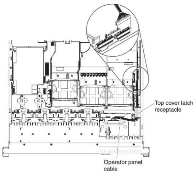
The following illustration shows the internal routing and connector for the USB/video cable.
Note: The USB cable is routed under the video cable and then both the USB and video cables are routed under the cable retention tab and the top cover latch receptacle.

The following illustration shows the internal routing for the configuration cable.
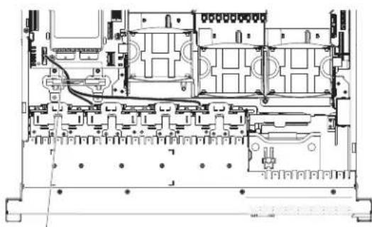
natural_image
Technical line drawing of an internal electronic device casing with circuitry and mounting brackets (no text or symbols)Configuration cable
The following illustrations show the internal routing for the SAS hard disk drive backplane cables (for a 16 hard disk drive model).
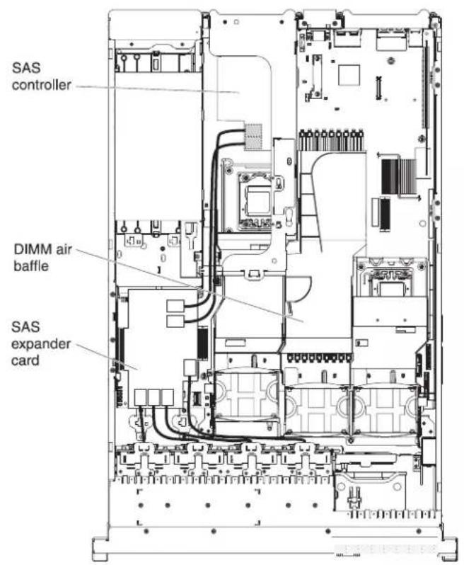
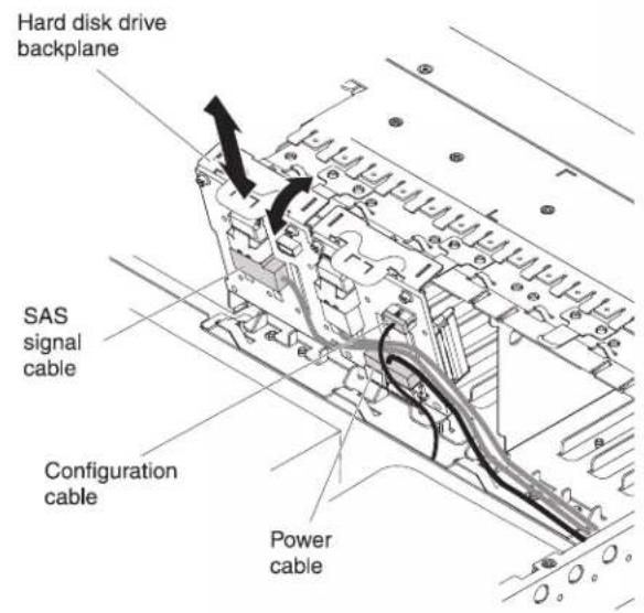
Removing the cover
The following illustration shows how to remove the cover.
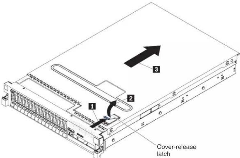
Important: Before you install optional hardware, make sure that the server is working correctly. Start the server, and make sure that the operating system starts, if an operating system is installed, or that a 19990305 error code is displayed, indicating that an operating system was not found but the server is otherwise working correctly. If the server is not working correctly, see the Problem Determination and Service Guide for diagnostic information.
To remove the cover, complete the following steps:
-
Read the safety information that begins on page vi and "Installation guidelines" on page 37.
-
If you are planning to view the error LEDs that are on the system board and components, leave the server connected to power and go directly to step 4
-
If you are planning to install or remove a microprocessor, memory module, PCI adapter, battery, or other non-hot-swap optional device, turn off the server and all attached devices and disconnect all external cables and power cords (see "Turning off the server" on page 22).
-
Press down on the left and right side latches and slide the server out of the rack enclosure until both slide rails lock.
Note: You can reach the cables on the rear of the server when the server is in the locked position.
- Press the blue latch 1 on the end of the cover-release latch and lift the cover-release latch 2. Slide the cover toward the rear 3 and lift the cover off the server. Set the cover aside.
Attention: For proper cooling and airflow and to avoid damaging server components, replace the cover before you turn on the server. If you operate the server for extended periods of time (over 30 minutes) with the cover removed, the IMM turns off the server.
Removing a PCI riser-card assembly
The server comes with one riser-card assembly (with option to add one more) that each contain two PCI Express x8 connectors. You can replace a PCI Express riser-card assembly with a riser-card assembly that contains one PCI Express Gen 2 x16 connector or that contains two PCI-X 64-bit 133 MHz connectors. See http://www.ibm.com/servers/eserver/serverproven/compat/us for a list of riser-card assemblies that you can use with the server.
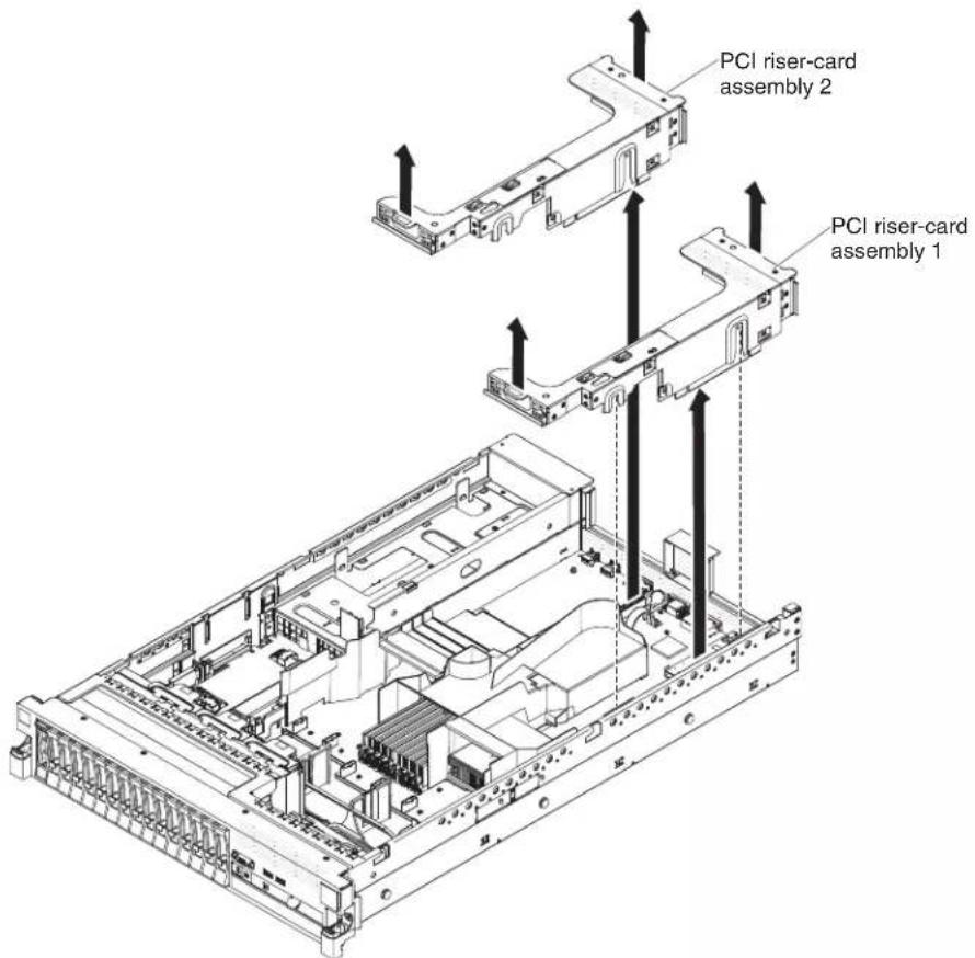
To remove the riser-card assembly, complete the following steps:
-
Read the safety information that begins on page 27 and "Installation guidelines" on page 37.
-
Turn off the server and peripheral devices, and disconnect the power cord and all external cables.
-
Remove the cover (see "Removing the cover" on page 45).
-
Grasp the assembly at the front tab and rear edge and lift it to remove it from the server. Place the riser-card assembly on a flat, static-protective surface.
Installing a PCI riser-card assembly
To install a PCI riser-card assembly, complete the following steps.
Note: The illustrations in this document might differ slightly from your hardware.

-
Read the safety information that begins on page vii and "Installation guidelines" on page 37.
-
Make sure that the server and all peripheral devices are turned off and that the power cords and all external cables are disconnected.
-
Reinstall any adapters and reconnect any internal cables that you removed in other procedures.
-
Align the PCI riser-card assembly with the selected PCI riser-card connector on the system board:
- PCI riser-card connector 1: Carefully fit the two alignment slots on the side of the assembly onto the two alignment brackets in the side of the chassis.
- PCI riser-card connector 2: Carefully align the bottom edge (the contact edge) of the riser-card assembly with the PCI riser-card connector on the system board.
- Press down on the assembly. Make sure that the riser-card assembly is fully seated in the riser-card connector on the system board.
If you have other devices to install, do so now. Otherwise, go to "Completing the installation" on page 139.
Removing the microprocessor 2 air baffle
When you work with some optional devices, you must first remove the microprocessor 2 air baffle to access certain components. The following illustration shows how to remove the microprocessor 2 air baffle.

To remove the microprocessor 2 air baffle, complete the following steps:
- Read the safety information that begins on page vi and "Installation guidelines" on page 37.
- Turn off the server and peripheral devices and disconnect all power cords and external cables (see "Turning off the server" on page 22).
- Remove the cover (see "Removing the cover" on page 45).
- Remove PCI riser-card assembly 2 if one is installed (see "Removing a PCI riser-card assembly" on page 46).
- Grasp the top of the air baffle and lift the air baffle out of the server.
Attention: For proper cooling and airflow, replace all air baffles before you turn on the server. Operating the server with any air baffle removed might damage server components.
Installing the microprocessor 2 air baffle
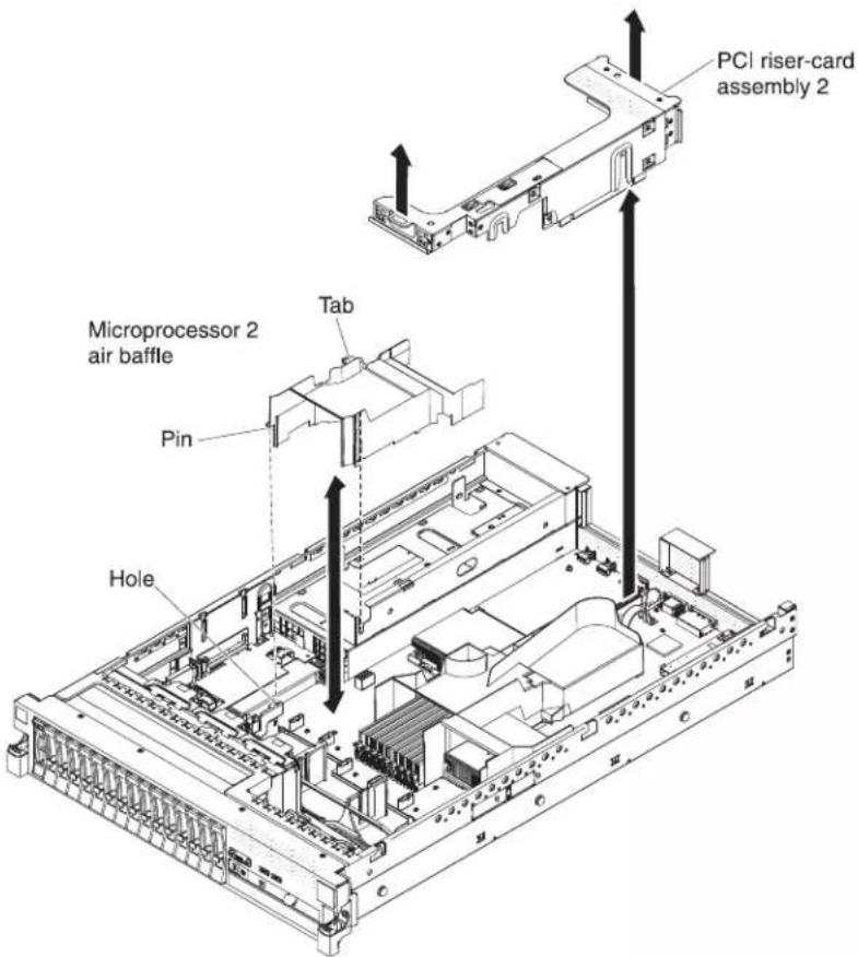
To install the microprocessor 2 air baffle, complete the following steps:
-
Read the safety information that begins on page vi and "Installation guidelines" on page 37.
-
Make sure that the server and peripheral devices are turned off (see "Turning off the server" on page 22) and that all power cords and external cables are disconnected.
-
Remove the cover (see "Removing the cover" on page 45).
-
Align the tab on the left side of the microprocessor 2 air baffle with the slot in the right side of the power-supply cage.
-
Lower the microprocessor 2 air baffle into the server. Make sure that the pin on the end of the air baffle is inserted into the hole on the system board (see the illustration).
Attention: For proper cooling and airflow, replace all air baffles before you turn on the server. Operating the server with any air baffle removed might damage server components.
Removing the DIMM air baffle
When you work with some optional devices, you must first remove the DIMM air baffle to access certain components or connectors on the system board. The following illustration shows how to remove the DIMM air baffle.

To remove the DIMM air baffle, complete the following steps:
- Read the safety information that begins on page vi and "Installation guidelines" on page 37.
- Turn off the server and peripheral devices and disconnect all power cords and external cables (see "Turning off the server" on page 22).
- Remove the cover (see "Removing the cover" on page 45).
- Remove PCI riser-card assembly 1, if needed (see "Removing a PCI riser-card assembly" on page 46).
- Place your fingers under the front and back of the top of the air baffle; then, lift the air baffle out of the server.
Attention: For proper cooling and airflow, replace all air baffles before you turn on the server. Operating the server with any air baffle removed might damage server components.
Installing the DIMM air baffle
The following illustration shows how to install the DIMM air baffle.

To install the DIMM air baffle, complete the following steps:
- Read the safety information that begins on page 6 and "Installation guidelines" on page 37.
- Make sure that the server and peripheral devices are turned off (see "Turning off the server" on page 22) and that all power cords and external cables are disconnected.
- Remove the cover (see "Removing the cover" on page 45).
- Make sure that PCI riser-card assembly 1 is removed (see "Removing a PCI riser-card assembly" on page 46).
- Align the DIMM air baffle with the DIMMs and the back of the fans.
- Lower the air baffle into place.
- Install PCI riser-card assembly 1, if needed (see "Installing a PCI riser-card assembly" on page 47.
Attention: For proper cooling and airflow, replace all air baffles before you turn on the server. Operating the server with any air baffle removed might damage server components.
Installing the full-length-adapter bracket
If you are installing a full-length adapter in the upper riser-card PCI slot, you must first install the full-length-adapter bracket in the end of the riser-card assembly.

To install the full-length-adapter bracket, complete the following steps:
- Orient the riser-card assembly as shown.
-
Remove the full-length-adapter bracket from the storage location.
a. Press the bracket tab 3 and slide the bracket toward the end of the riser-card assembly.
b. Push the bracket out of the storage location on the riser-card assembly. -
Align the bracket with the end of the riser-card assembly as shown.
-
Place the two hooks 1 in the two openings 2 in the end of the riser-card assembly.
-
Press the bracket tab 3 and slide the bracket to the right until it clicks into place.
-
Return to the adapter-installation instructions.
Storing the full-length-adapter bracket
If you are removing a full-length adapter in the upper riser-card PCI slot and will replace it with a shorter adapter or no adapter, you must remove the full-length-adapter bracket from the end of the riser-card assembly and return the bracket to its storage location.
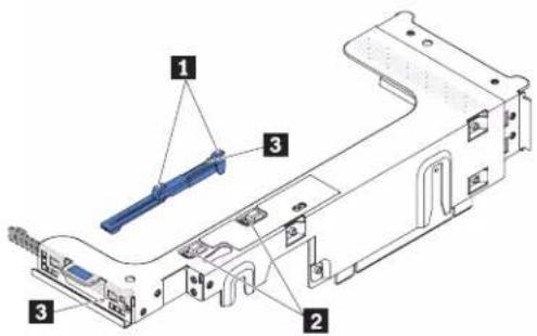
To remove and store the full-length-adapter bracket, complete the following steps:
- Press the bracket tab 3 and slide the bracket to the left until the bracket falls free of the riser-card assembly.
- Align the bracket with the storage location on the riser-card assembly as shown.
-
Place the two hooks 1 in the two openings 2 in the storage location on the riser-card assembly.
-
Press the bracket tab 3 and slide the bracket toward the expansion-slot-opening end of the assembly until the bracket clicks into place.
-
Return to "Installing a PCI adapter" or "Installing a PCI riser-card assembly" on page 47, as applicable.
Installing a PCI adapter
The following illustration shows the PCI adapter expansion slots from the rear of the server.

The following notes describe the types of adapters that the server supports and other information that you must consider when you install an adapter:
- Locate the documentation that comes with the adapter and follow those instruction in addition to the instructions in this section. If you have to change switch settings or jumper settings on the adapter, follow the instructions that come with the adapter.
- To ensure that a ServeRAID-10i, ServeRAID-10is, or ServeRAID-10M adapter works correctly in your UEFI-based server, make sure that the adapter firmware is at the latest level.
Important: Some cluster solutions require specific code levels or coordinated code updates. If the device is part of a cluster solution, verify that the latest level of code is supported for the cluster solution before you update the code.
- Some high performance video adapters are supported by your server. See http://www.ibm.com/servers/eserver/serverproven/compat/us/ for more information.
- The following notes describe important information about the NVIDIA video adapter that comes preinstalled in some server models:
- Do not set the maximum digital video resolution above 1600 x 1200 at 75 Hz for an LCD monitor. This is the highest resolution that is supported for an optional video adapter in the server.
- Any high-definition video-out connector or stereo connector on an optional video adapter is not supported.
- A PCI Express Gen 2 x16 riser card can support only one adapter.
- A PCI Express Gen 2 x8 riser card and a PCI-X riser card can each support two adapters.
- The expansion slots in the PCI riser cards accommodate the various form factors of the non-hot-plug adapters as follows:
- Expansion slot 1: Full-height, full-length
- Expansion slot 2: Low-profile with standard bracket
- Expansion slot 3: Full-height, full-length
- Expansion slot 4: Full-height, half-length
Note: If you are installing x3650 M3 PCI Express Gen 2 x8 riser card (part number 59Y3818), you cannot install any adaptor in slot 1.
If you install a different supported riser-card assembly, the supported adapter types might be different. For a list of supported riser-card assemblies, see http://www.ibm.com/servers/eserver/serverproven/compat/us/.
- The system scans devices in the following order, if you have not changed the default boot precedence:
– Video Unified Extensible Firmware Interface (UEFI) (fixed)
– System board Ethernet 1 PXE (fixed)
– System board Ethernet 2 PXE (fixed)
– System board SAS (or RAID)
The following illustration shows the adapter connectors on the PCI riser-card assembly.
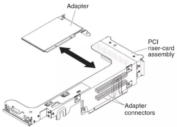
To install a PCI adapter, complete the following steps:
- Read the safety information that begins on page vii and "Installation guidelines" on page 37.
- Turn off the server and peripheral devices and disconnect all power cords and external cables (see "Turning off the server" on page 22).
- Remove the cover (see "Removing the cover" on page 45).
- Determine which expansion slot you will use for the adapter.
- If you are installing an adapter in PCI expansion slot 1 or 2, remove PCI riser-card assembly 1; if you are installing an adapter in PCI expansion slot 3 or 4, remove PCI riser-card assembly 2. See "Removing a PCI riser-card assembly" on page 46.
- Slide the expansion-slot cover out of the PCI riser-card assembly expansion slot.
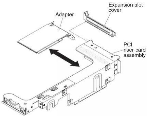
- Install the adapter:
a. If the adapter is a full-length adapter for the upper expansion slot in the riser card, remove the full-length-adapter bracket from underneath the top of the riser-card assembly and insert it in the end of the upper expansion slot of the riser-card assembly. See "Installing the full-length-adapter bracket" on page 52 for instructions.
b. Align the adapter with the adapter connector on the riser-card and the guide on the external end of the PCI riser-card assembly.
c. Press the adapter firmly into the adapter connector on the riser card.

- Connect any required cables to the adapter.
Attention:
- When you route cables, do not block any connectors or the ventilated space around any of the fans.
- Make sure that cables are not routed on top of components that are under the PCI riser-card assembly.
-
Make sure that cables are not pinched by the server components.
-
Align the PCI riser-card assembly with the selected PCI riser-card connector on the system board.
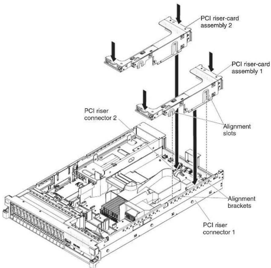
- PCI riser-card connector 1: Carefully fit the two alignment slots on the side of the assembly onto the two alignment brackets in the side of the chassis; align the rear of the assembly with the guides on the rear of the server.
- PCI riser-card connector 2: Carefully align the bottom edge (the contact edge) of the riser-card assembly with the PCI riser-card connector on the system board; align the rear of the assembly with the guides on the rear of the server.
- Press down on the assembly. Make sure that the riser-card assembly is fully seated in the PCI riser-card connector on the system board.
- Perform any configuration tasks that are required for the adapter.
If you have other devices to install or remove, do so now. Otherwise, go to "Completing the installation" on page 139.
Removing a PCI adapter
To remove an adapter from a PCI riser-card assembly, complete the following steps.
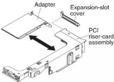
-
Read the safety information that begins on page vii and "Installation guidelines" on page 37.
-
Turn off the server and peripheral devices and disconnect all power cords and external cables (see "Turning off the server" on page 22).
-
Press down on the left and right side rack latches and slide the server out of the rack enclosure until both slide rails lock; then, remove the cover (see "Removing the cover" on page 45).
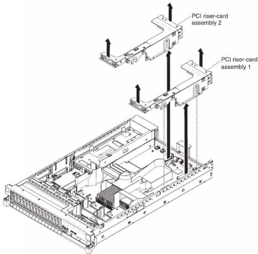
-
Remove the PCI riser-card assembly that contains the adapter (see "Removing a PCI riser-card assembly" on page 46).
-
Disconnect any cables from the adapter (make note of the cable routing, in case you reinstall the adapter later).
-
Carefully grasp the adapter by its top edge or upper corners, and pull the adapter from the PCI expansion slot.
If you have other devices to install or remove, do so now. Otherwise, go to "Completing the installation" on page 139.
Installing an IBM Virtual Media Key
The optional IBM Virtual Media Key enables the IMM remote presence and blue-screen capture capability. This feature provides graphical console redirection with remote keyboard and mouse interaction, plus remote diskette and CD/DVD drive support.
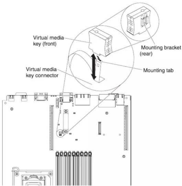
To install a virtual media key, complete the following steps:
-
Read the safety information that begins on page vi and "Installation guidelines" on page 37.
-
Turn off the server and peripheral devices and disconnect all power cords and external cables (see "Turning off the server" on page 22).
-
Remove the cover (see "Removing the cover" on page 45).
-
Align the mounting bracket on the rear of the virtual media key with the mounting tab and slide it down the tab onto the virtual medial key connector on the system board. Press the virtual media key down into the connector until it is firmly seated on the system board.
If you have other devices to install or remove, do so now. Otherwise, go to "Completing the installation" on page 139.
Installing a hard disk drive
The following notes describe the type of hard disk drives that the server supports and other information that you must consider when you install a drive. For a list of supported drives, see http://www.ibm.com/servers/eserver/serverproven/compat/us/.
Important: Do not install a SCSI hard disk drive in this server.
- Locate the documentation that comes with the hard disk drive and follow those instructions in addition to the instructions in this chapter.
- The server supports eight 2.5-inch hot-swap or simple-swap hard disk drives installed on Ultra-Slim hard disk drive trays. An optional 8-drive-bay kit is available for 16-drive-capable server models. For a list of supported 2.5-inch hard disk drives, see http://www.ibm.com/servers/eserver/serverproven/compat/us/.
- All hot-swap drives in the server should have the same throughput speed rating. Using hard disk drives with different speed ratings will cause all drives to operate at the throughput speed of the slowest drive.
- The ID that is assigned to each bay is printed on the front of the server, above the drive bay.
The following illustration shows how to install a hot-swap hard disk drive.
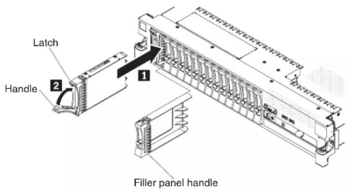
To install a drive in a hot-swap bay, complete the following steps.
Attention: To maintain proper system cooling, do not operate the server for more than 10 minutes without either a drive or a filler panel installed in each bay.
- Read the safety information that begins on page vii, "Installation guidelines" on page 37, and "Handling static-sensitive devices" on page 39.
- Remove the filler panel from one of the empty hot-swap bays: Grasp the filler panel handle and pull the filler panel away from the server.
- Install the hard disk drive in the hot-swap bay:
a. Orient the drive as shown in the illustration.
b. Make sure that the tray handle is open.
c. Align the drive assembly with the guide rails in the bay.
d. Gently push the drive assembly into the bay until the drive stops 1.
e. Push the tray handle to the closed (locked) position 2.
f. If the system is turned on, check the hard disk drive status LED to verify that the hard disk drive is operating correctly.
After you install a hard disk drive, the green activity LED flashes as the disk spins up. The amber LED turn off after about 1 minute. If the new drive starts to rebuild, the amber LED flashes slowly and the green activity LED remains lit during the rebuild process. If the amber LED remains lit, see the Problem Determination and Service Guide on the IBM Documentation CD for hard disk drive problem solutions.
Note: You might have to reconfigure the disk arrays after you install hard disk drives. See the RAID documentation on the IBM ServeRAID Support CD for information about RAID controllers.
If you have other devices to install or remove, do so now. Otherwise, go to "Completing the installation" on page 139.
Removing a hard disk drive
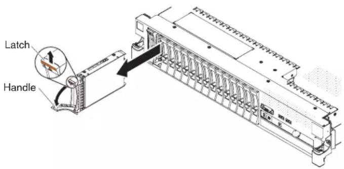
To remove a hot-swap hard disk drive, complete the following steps:
- Read the safety information that begins on page vii, "Installation guidelines" on page 37, and "Handling static-sensitive devices" on page 39.
- Press up on the release latch at the top of the drive front.
- Move the handle on the drive to the open position (perpendicular to the drive).
- Pull the hot-swap drive assembly out of the bay approximately 25 mm (1 in.). Wait approximately 45 seconds while the drive spins down before you remove the drive assembly completely from the bay.
Note: You might have to reconfigure the disk arrays after you remove a hard disk drive. See the RAID documentation on the IBM ServeRAID Support CD for information about RAID controllers.
If you have other devices to install or remove, do so now. Otherwise, go to "Completing the installation" on page 139.
Installing a simple-swap hard disk drive
Locate the documentation that comes with the hard disk drive and follow those instructions in addition to the instructions in this section.
Simple-swap models do not support the SAS hot-swap backplane or the SAS riser-card.
For information about the type of hard disk drive that the server supports and other information that you must consider when installing a hard disk drive, see the Installation and User's Guide on the IBM Documentation CD.
Important: Do not install a SCSI hard disk drive in this server.

To install a drive in a simple-swap bay, complete the following steps.
Attention: To maintain proper system cooling, do not operate the server for more than 10 minutes without either a drive or a filler panel installed in each bay.
- Remove the drive filler panel from the front of the server.
- Orient the drive as shown in the illustration.
- Align the drive assembly with the guide rails in the bay.
- Gently push the drive assembly into the bay until the drive stops.
Note: You might have to reconfigure the disk arrays after you install hard disk drives. See the RAID documentation on the IBM ServeRAID Support CD for information about RAID controllers.
Removing a simple-swap hard disk drive

Attention: To maintain proper system cooling, do not operate the server for more than 10 minutes without either a drive or a filler panel installed in each bay.
To remove a hard disk drive from a simple-swap bay, complete the following steps.
- Read the safety information that begins on page vii, "Installation guidelines" on page 37, and "Handling static-sensitive devices" on page 39.
- Remove the drive filler panel.
- Push drive into the bay until it latches into place.
- Replace the drive filler panel.
Installing a SAS/SATA 4 Pac HDD upgrade option
If the server is a 16-drive-capable model with four hard disk drive bays installed, you can install an IBM System x3650 M3 Hot-swap SAS/SATA 4 Pac HDD upgrade option. See http://www.ibm.com/servers/eserver/serverproven/compat/us, for a list of supported optional devices. To order a SAS/SATA 4 Pac HDD upgrade option, contact your IBM marketing representative or authorized reseller.
Note: You need to install the SAS/SATA 4 Pac HDD upgrade option first in order to upgrade to either SAS/SATA 16 Pac HDD system or a 8 Pac HDD + tape system.
The SAS/SATA 4 Pac HDD upgrade option kit contains the following components:
- Four M3.5 screws
• One blank EMC filler
• Four drive bay filler panels - Two backplane brackets
• One ServeRaid controller
• One SAS signal cable
• One internal power cable - One backplane bracket
• One 2.5-inch hard disk drive backplane
To install a 4-disk-drive optional hard disk drive backplane in a 8-drive-capable server model, complete the following steps:
- Read the safety information that begins on page vi and "Installation guidelines" on page 37.
- Turn off the server and disconnect all power cords and external cables (see "Turning off the server" on page 22).
- Remove the server cover (see "Removing the cover" on page 45).
- Remove the three 4-drive filler panels that are to the right of drive bay 4, beneath the IDs 4 - 1 5 on the front bezel.
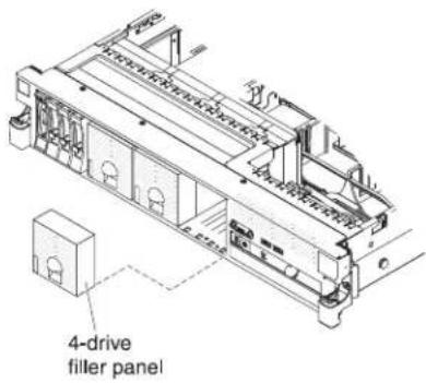
- To obtain more working room, remove fans 2 and 3 (see "Removing a hot-swap fan" on page 115).
- Pull the hard disk drives or fillers out of the server slightly to disengage them from the backplanes. For more information, see "Removing a hard disk drive" on page 60.
- Disconnect the SAS signal cable from the SAS controller, which is connected to the SAS riser-card. Leave the other end of the SAS signal cable connected to the hard disk drive backplane.
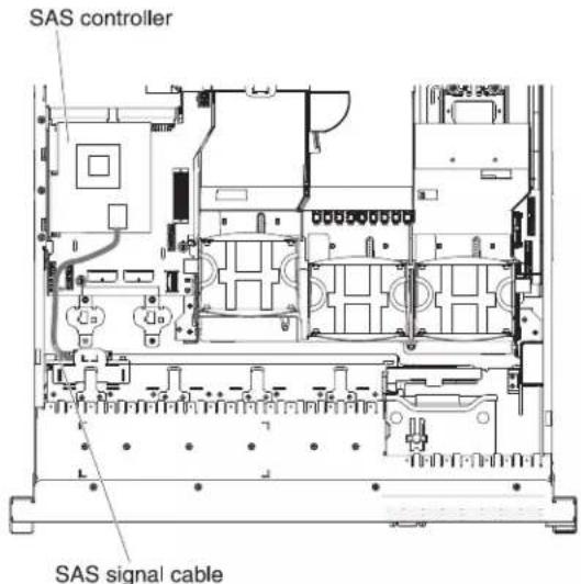
- Remove the SAS controller assembly from the server; then, remove the SAS controller from the SAS riser-card. See 'Removing a ServeRAID SAS controller from the SAS riser-card" on page 121 for instructions.

- Remove the SAS controller front retention bracket from the server.

- Connect one end of the internal power cable that comes with the 4 Pac HDD upgrade option kit into the hot-swap SAS/SATA power connector on the system board.

- Remove hard disk drive backplane from the server.
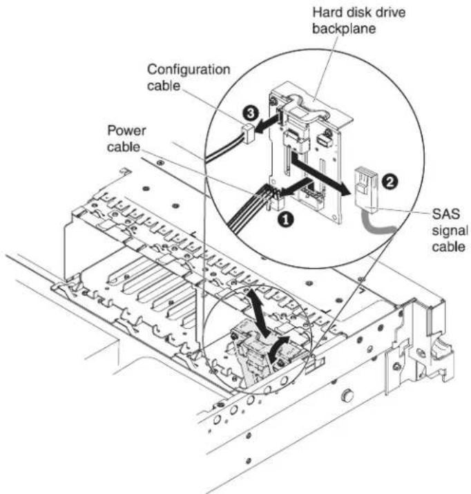
a. From backplane, disconnect the following cables in the order listed:
- Power cable 1
- SAS signal cable 2
- Configuration cable 3
b. Lift the backplane out of the server by pulling it toward the rear of the server and then lifting it up.
- Install the new backplane:
a. Move the SAS signal cable from the old hard disk drive backplane to the new backplane 1. The new backplane comes with the option kit.
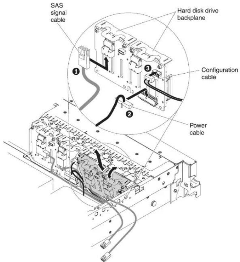
b. Connect the new power cable that comes with the option kit to the new hard disk drive backplane 2.
c. Connect the configuration cable to the new backplane 3.
d. Angle the new backplane and place the bottom edge into the slots for it on the chassis.
e. Rotate the backplane upright so that the bracket goes underneath the latch and tabs on the chassis and is engaged into the slots on the backplane bracket.
-
Make sure that the configuration cable is connected to the backplane.
-
Remove the rear controller retention bracket located in the battery bay above the power supplies by pulling up the release tab 1 and sliding the bracket outward 2.
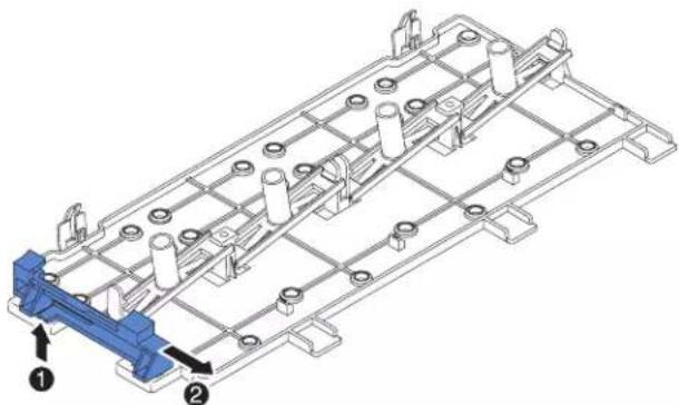
natural_image
Technical line drawing of a mechanical assembly with numbered components (no text or symbols)- Install the SAS controller front retention bracket that you got from step 14:
a. Align the retention bracket controller slot so that it faces the rear of the server.

b. Place the bracket tabs in the holes on the chassis and slide the bracket to left until it clicks into place.
-
Remove the fillers (if they are installed) from the two connectors on the SAS controller that comes with the option kit.
-
Install the SAS controller:
a. Insert the SAS controller into the connector on the SAS riser-card.
b. Insert the front of the SAS controller into the front retention bracket.
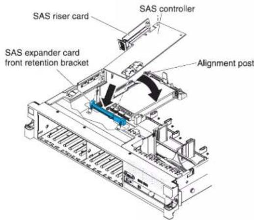
c. Install the SAS riser-card with the SAS controller into the connector on the system board, making sure that the alignment post goes through the hole in the controller. Press the riser card into place until the latch at the rear of the card snaps closed.
- Connect the SAS signal cables to the SAS controller:
a. Connect the SAS signal cable from the right side of the hard disk drive backplane to the right front connector on the SAS controller (as facing the front of the server).
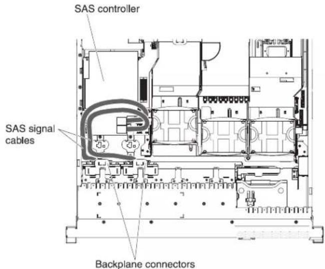
b. Connect the SAS signal cable that comes with the 4 Pac HDD upgrade option kit from the left side of the hard disk drive backplane to the left front connector on the SAS controller (as facing the front of the server).
- If you removed any fans, install them.
- Insert the hard disk drives and the fillers the rest of the way into the bays.
If you have other devices to install or remove, do so now. Otherwise, go to "Completing the installation" on page 139.
Installing a SAS/SATA 8 Pac HDD option
If the server is a 16-drive-capable model with eight hard disk drive bays installed, you can install an IBM System x3650 M3 Hot-swap SAS/SATA 8 Pac HDD option. See http://www.ibm.com/servers/eserver/serverproven/compat/us, for a list of supported optional devices. To order a SAS/SATA 8 Pac HDD option, contact your IBM marketing representative or authorized reseller.
The SAS/SATA 8 Pac HDD option kit contains the following components:
• One 2.5-inch hard disk drive backplane
• One SAS expander card
- Four M3 screws
• One remote battery cable
• Eight blank EMC fillers
- Four SAS signal cables (one cable has a right-angle connector)
• One internal power cable
- Two backplane brackets
To install a 8-disk-drive optional hard disk drive backplane in a 16-drive-capable server model, complete the following steps:
- Read the safety information that begins on page vi and "Installation guidelines" on page 37.
- Turn off the server and disconnect all power cords and external cables (see "Turning off the server" on page 22).
-
Remove the server cover (see "Removing the cover" on page 45).
-
Remove the two 4-drive filler panels that are to the right of drive bay 8, beneath the IDs 8 - 1 5 on the front bezel.
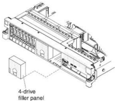
-
To obtain more working room, remove fans 2 and 3 (see "Removing a hot-swap fan" on page 115).
-
Pull the hard disk drives or fillers out of the server slightly to disengage them from the backplanes. For more information, see "Removing a hard disk drive" on page 60.
-
Disconnect the SAS signal cables from the SAS controller, which is connected to the SAS riser-card. Leave the other end of the SAS signal cables connected to the hard disk drive backplanes.
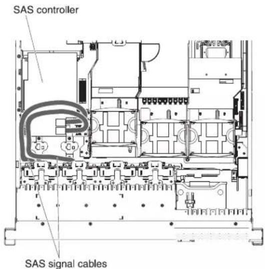
- Remove the SAS controller assembly from the server; then, remove the SAS controller from the SAS riser-card. See "Removing a ServeRAID SAS controller from the SAS riser-card" on page 121 for instructions.

- Remove the SAS controller front retention bracket from the server.

- Connect one end of the internal power cable that comes with the 8 Pac HDD option kit into the empty hot-swap SAS/SATA power connector on the system board.
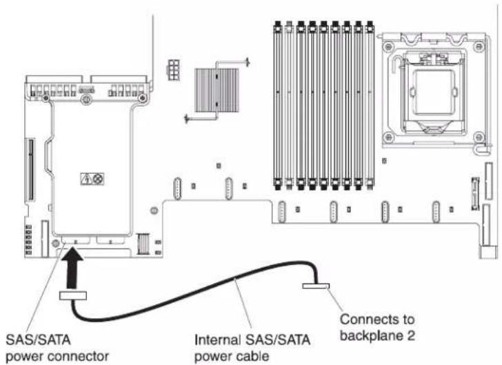
- Remove hard disk drive backplane 1 from the server.

a. From backplane 1, disconnect the following cables in the order listed:
- Power cable 1
- SAS signal cable 2
- Configuration cable 3
b. Lift backplane 1 out of the server by pulling it toward the rear of the server and then lifting it up.
- Install the new backplane in slot 2:
a. Move the SAS signal cable from hard disk drive backplane 1 to new backplane 2 1. The new backplane comes with the option kit.

b. Connect the new power cable that comes with the option kit to new hard disk drive backplane 2 2.
c. Connect the configuration cable to backplane 2 3.
d. Angle the new backplane and place the bottom edge into the slots for backplane 2 on the chassis next to the optical drive.

e. Rotate the backplane upright so that the bracket goes underneath the latch and tabs on the chassis and is engaged into the slots on the backplane bracket.
- Install hard disk drive backplane 1:
a. Connect the right-angle end of the longer SAS signal cable that comes with the option kit to hard disk drive backplane 1 1.

b. Reconnect the power cable 2 to backplane 1.
c. Reconnect the configuration cable 3 to backplane 1.
d. Angle the backplane and place the bottom edge into the slots for backplane 1 on the chassis.
e. Rotate the backplane upright so that the bracket goes underneath the latch and tabs on the chassis and is engaged into the slots on the backplane bracket.
-
Make sure that the configuration cable is connected to all backplanes.
-
Remove the rear controller retention bracket located in the battery bay above the power supplies by pulling up the release tab 1 and sliding the bracket outward 2.

natural_image
Technical line drawing of a mechanical assembly with numbered components (no text or symbols)- Install the SAS controller front retention bracket that you got from step 15:
a. Align the retention bracket controller slot so that it faces the rear of the server.

b. Place the bracket tabs in the holes on the chassis and slide the bracket to left until it clicks into place.
- Remove the fillers (if they are installed) from the four connectors on the SAS expander card that comes with the option kit.

- Install the SAS expander card:
a. Insert the SAS expander card into the connector on the SAS riser-card.
b. Insert the front of the SAS expander card into the front retention bracket.
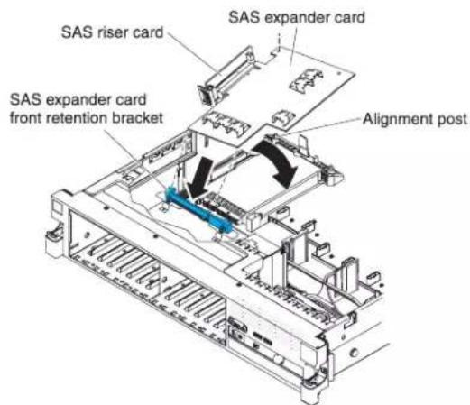
c. Install the SAS riser-card with the SAS expander card into the connector on the system board, making sure that the alignment post goes through the hole in the expander card. Press the riser card into place until the latch at the rear of the card snaps closed.
- If a battery and battery carrier are attached to the SAS controller that you removed in step 3 disconnect the battery carrier cable from the battery and remove the three screws that secure the battery carrier to the SAS controller. Set the battery and battery carrier aside.
Note: The illustrations in this document might differ slightly from your hardware.
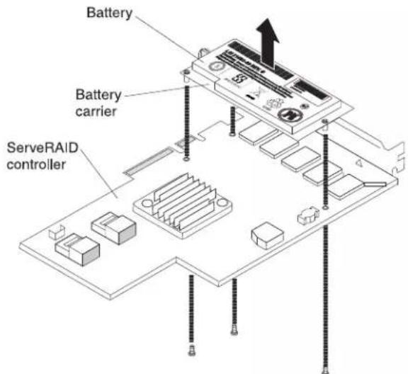
- Install the interposer card that comes with the option kit on the interposer card connector on the SAS controller:
a. Remove the interposer card and the loose screw from the bag.
b. Rotate the standoff so that it aligns with the hole in the ServeRAID controller, and position the interposer card connector over the SAS controller connector.

c. Press the interposer card down onto the interposer card connector so that the interposer card is secured.
d. From the other side of the SAS controller, insert and tighten the screw to secure the interposer card to the SAS controller.
- Remove the expansion-slot bracket that is screwed to the vertical wall above the power supply and install the expansion-slot bracket on the SAS controller:
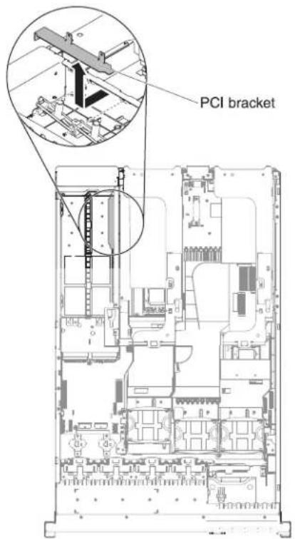
a. Orient the SAS controller as shown in the illustration.
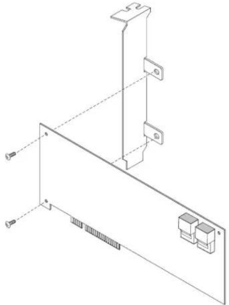
natural_image
Technical line drawing of a mechanical assembly with mounting brackets and connectors (no text or symbols)b. Align the metal bracket so that the tabs are on the back side of the SAS controller and the holes on the tabs align with the holes on the SAS controller.
c. From the front side of the SAS controller, install the two screws that hold the metal bracket onto the SAS controller.
- If required, connect one end of the remote battery cable to the interposer card.
Attention: To avoid damage to the hardware, make sure that you align the black dot on the cable connector with the black dot on the connector on the interposer card. Do not force the remote battery cable into the connector.
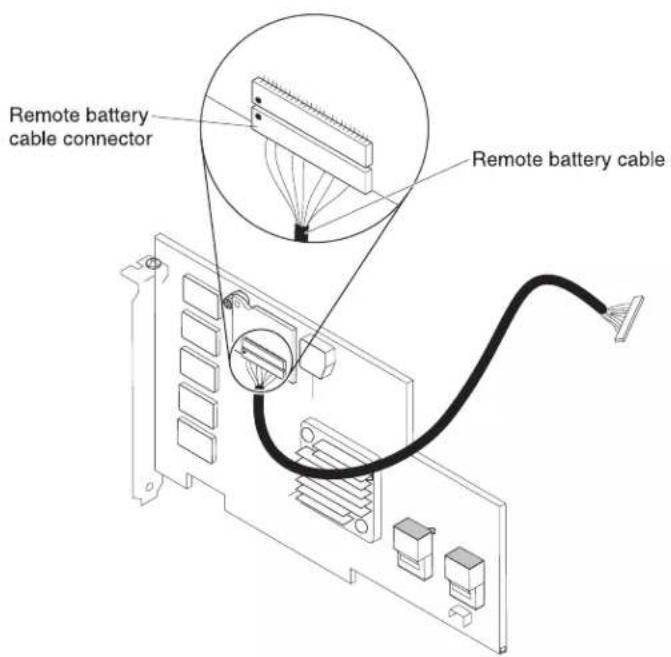
- Connect the shorter SAS signal cable that comes with the option kit to the SAS controller connector that is labeled "Ports 7-4".
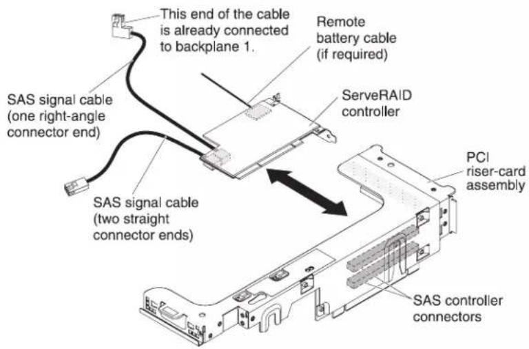
Notes:
a. If you are connecting the shorter SAS signal cable to a ServeRAID-BR10i v2 SAS/SATA Controller, the connectors are reversed. You must connect the shorter SAS signal cable to the connector that is labeled "Port 4-7", which is the connector that is not the closest to the edge of the controller.
b. If you are connecting the longer SAS signal cable to a ServeRAID-BR10i v2 SAS/SATA Controller, the connectors are reversed. You must connect the straight connector end of the longer SAS signal cable to the connector that is labeled "Port 0-3".
-
Remove the PCI riser-card assembly (see "Removing a PCI riser-card assembly" on page 46).
-
Orient the SAS controller so that the connectors are on the underside of the controller. Install the SAS controller in the connector on the PCI riser card. (See the previous illustration and see "Installing a PCI adapter" on page 53.)
-
Install the PCI riser-card assembly in the server (see "Installing a PCI riser-card assembly" on page 47).
-
Connect the free end of the remote battery cable to the battery on the remote battery tray. For more information, see Installing a ServeRAID SAS controller battery on the remote battery tray" on page 126.
-
Connect the SAS signal cables to the SAS expander card:
a. Connect the SAS signal cables from hard disk drive backplane 2 to the right front connectors on the SAS expander card (as facing the front of the server).
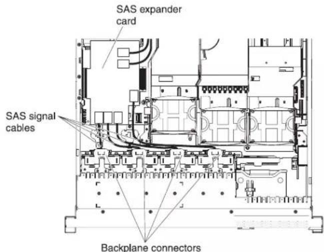
b. Connect the SAS signal cables from hard disk drive backplane 1 to the left front connectors on the SAS expander card (as facing the front of the server).
- Connect the loose end of the SAS signal cables (the cables have straight connectors and are already connected to the ServRAID controllers) to the rear connectors on the SAS expander card. Route the cable underneath the cable retention features on the baffle. See the illustration.
Note: The cables that connect to a ServeRAID-BR10i v2 SAS/SATA Controller are reversed.

- If you removed any fans, install them.
- Insert the hard disk drives and the fillers the rest of the way into the bays.
If you have other devices to install or remove, do so now. Otherwise, go to "Completing the installation" on page 139.
Installing a SAS/SATA 8 Pac HDD for 2 RAID kit with 2 M5015 adapters option
If the server is a 16-drive-capable model with eight hard disk drive bays installed, you can install an IBM System x3650 M3 Hot-swap SAS/SATA 8 Pac HDD option. See http://www.ibm.com/servers/eserver/serverproven/compat/us for a list of supported optional devices. To order a SAS/SATA 8 Pac HDD for 2 RAID kit with 2 M5015 adapters option, contact your IBM marketing representative or authorized reseller.
The SAS/SATA 8 Pac HDD for 2 RAID kit with 2 M5015 adapters option contains the following components:
• One 2.5-inch hard disk drive backplane
- Two M5015 adapters
- Four M3 screws
• Eight blank EMC fillers - Two SAS signal cables
• One remote battery cable
• One internal power cable - Two backplane brackets
To install a SAS/SATA 8 Pac HDD for 2 RAID kit with 2 M5015 adapters in a 16-drive-capable server model, complete the following steps:
- Read the safety information that begins on page vi and "Installation guidelines" on page 37.
- Turn off the server and disconnect all power cords and external cables (see "Turning off the server" on page 22).
- Remove the server cover (see "Removing the cover" on page 45).
- Remove the two 4-drive filler panels that are to the right of drive bay 8, beneath the IDs 8 - 1 5 on the front bezel.
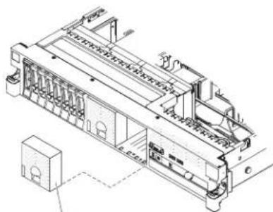
natural_image
Technical line drawing of a mechanical assembly with no visible text or symbols4-drive filler panel
- To obtain more working room, remove fans 2 and 3 (see "Removing a hot-swap fan" on page 115).
- Pull the hard disk drives or fillers out of the server slightly to disengage them from the backplanes. For more information, see "Removing a hard disk drive" on page 60.
- Disconnect the SAS signal cables from the SAS controller, which is connected to the SAS riser-card. Leave the other end of the SAS signal cables connected to the hard disk drive backplanes.
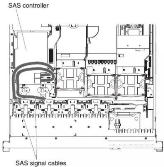
- Remove the SAS controller assembly from the server; then, remove the SAS controller from the SAS riser-card. See "Removing a ServeRAID SAS controller from the SAS riser-card" on page 121 for instructions.
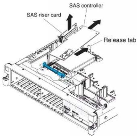
- Remove the SAS controller front retention bracket from the server.

- Connect one end of the internal power cable that comes with the 8 Pac HDD option kit into the empty hot-swap SAS/SATA power connector on the system board.
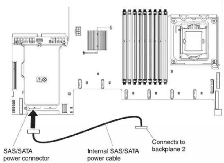
- Remove hard disk drive backplane 1 from the server.
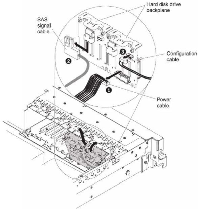
a. From backplane 1, disconnect the following cables in the order listed:
- Power cable 1
- SAS signal cable 2
- Configuration cable 3
b. Lift backplane 1 out of the server by pulling it toward the rear of the server and then lifting it up.
- Install the new backplane in slot 2:
a. Move the SAS signal cable from hard disk drive backplane 1 to new backplane 2 1. The new backplane comes with the option kit.
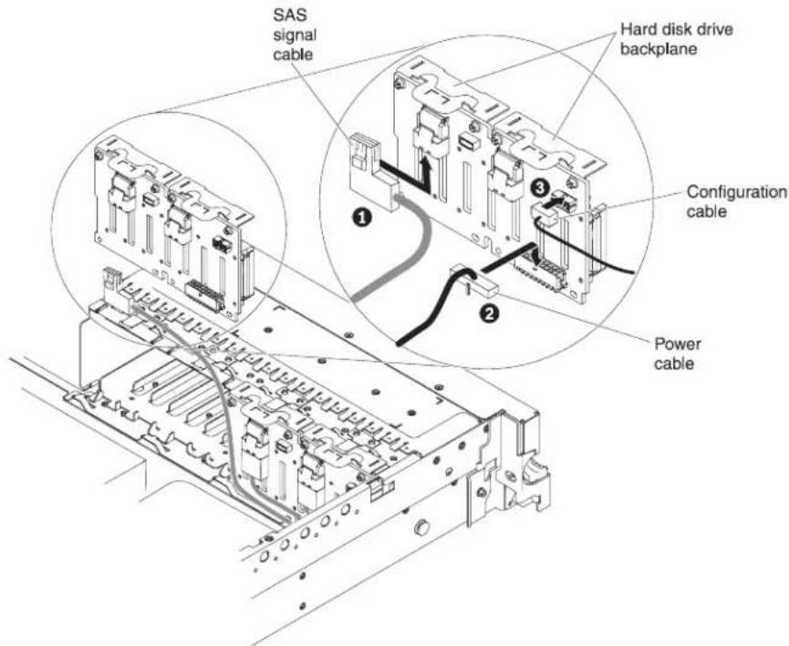
b. Connect the new power cable that comes with the option kit to new hard disk drive backplane 2 2.
c. Connect the configuration cable to backplane 2 3 .
d. Angle the new backplane and place the bottom edge into the slots for backplane 2 on the chassis next to the optical drive.
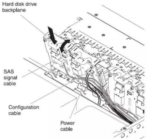
e. Rotate the backplane upright so that the bracket goes underneath the latch and tabs on the chassis and is engaged into the slots on the backplane bracket.
- Install hard disk drive backplane 1:
a. Connect the right-angle end of the longer SAS signal cable that comes with the option kit to hard disk drive backplane 1 1.

b. Reconnect the power cable 2 to backplane 1.
c. Reconnect the configuration cable 3 to backplane 1.
d. Angle the backplane and place the bottom edge into the slots for backplane 1 on the chassis.
e. Rotate the backplane upright so that the bracket goes underneath the latch and tabs on the chassis and is engaged into the slots on the backplane bracket.
-
Make sure that the configuration cable is connected to all backplanes.
-
Remove the rear controller retention bracket located in the battery bay above the power supplies by pulling up the release tab 1 and sliding the bracket outward 2.

natural_image
Technical line drawing of a mechanical assembly with numbered components (no text or symbols)- Install the SAS controller front retention bracket that you got from step 15.
a. Align the retention bracket controller slot so that it faces the rear of the server.

b. Place the bracket tabs in the holes on the chassis and slide the bracket to left until it clicks into place.
-
Remove the fillers (if they are installed) from the connectors on the M5015 adapters that come with the option kit.
-
Install one of the M5015 adapters:
a. Insert an M5015 adapter into the connector on the SAS riser-card.
b. Insert the front of the M5015 adapter into the front retention bracket.
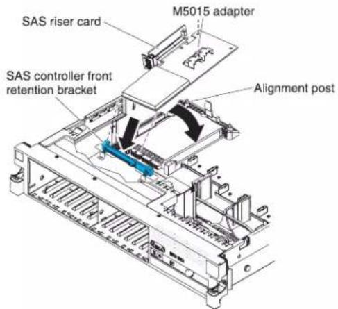
c. Install the SAS riser-card with the M5015 adapter into the connector on the system board, making sure that the alignment post goes through the hole in the controller. Press the riser card into place until the latch at the rear of the card snaps closed.
- Remove the expansion-slot bracket that is screwed to the vertical wall above the power supply and install the expansion-slot bracket on another M5015 adapter:
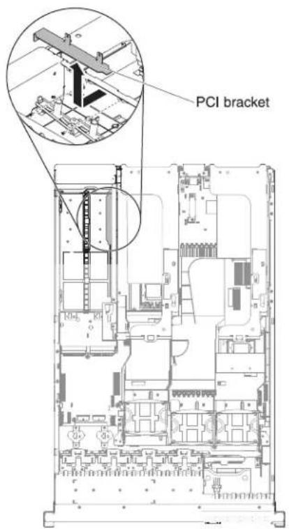
a. Orient the M5015 adapter as shown in the illustration.
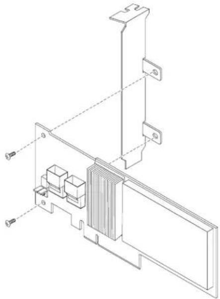
natural_image
Technical line drawing of a mechanical assembly with mounting brackets and internal components (no text or symbols)b. Align the metal bracket so that the tabs are on the back side of the SAS controller and the holes on the tabs align with the holes on the SAS controller.
c. From the front side of the M5015 adapter, install the two screws that hold the metal bracket onto the M5015 adapter.
- Connect the SAS signal cables to the connectors on the M5015 adapter:
a. Connect the shorter SAS signal cable that comes with the option kit to the M5015 adapter connector that is labeled "Ports 3-0".
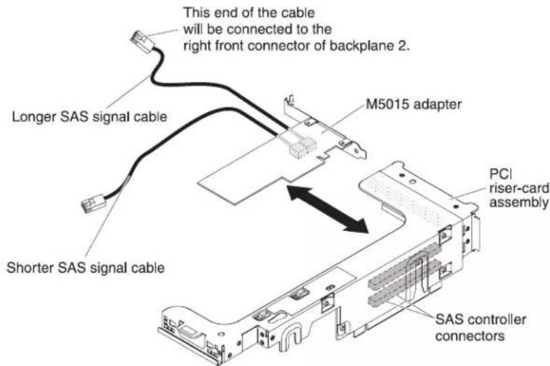
b. Connect the longer SAS signal cable to the other SAS connector that is labeled "Ports 7-4".
-
Remove the PCI riser-card assembly 2 (see the "Removing a PCI riser-card assembly" section of the IBM System x3650 M3 Installation and User's Guide).
-
Orient the M5015 adapter so that the connectors are on the underside of the controller. Install the M5015 adapter in the connector on the PCI riser card (PCI slot 4, see the previous illustration and see the "Installing a PCI adapter" section of the IBM System x3650 M3 Installation and User's Guide).
-
Install the PCI riser-card assembly 2 in the server (see the "Installing a PCI riser-card assembly" section of the IBM System x3650 M3 Installation and User's Guide).
-
Connect the SAS signal cables to the M5015 adapter installed on the bottom left corner (as facing the front of the server):
a. Connect the SAS signal cable from the left front connector of hard disk drive backplane 1 to the lower connector on the M5015 adapter (as facing the front of the server).
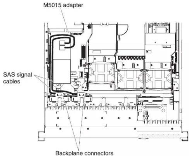
b. Connect the SAS signal cable from the right front connector of hard disk drive backplane 1 to the upper connector on the M5015 adapter (as facing the front of the server).
- Connect the SAS signal cables from the connectors on the M5015 adapter installed on the back of the server. Route the cable underneath the cable retention features on the baffle. See the illustration.
a. Connect the shorter SAS signal cable to the left front connector of hard disk drive backplane 2.
b. Connect the longer SAS signal cable to the right front connector of hard disk drive backplane 2.
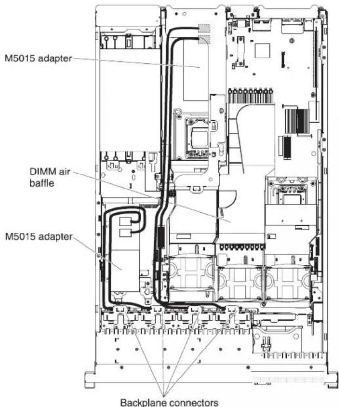
- If you removed any fans, install them.
- Insert the hard disk drives the rest of the way into the bays.
If you have other devices to install or remove, do so now. Otherwise, go to "Completing the installation" on page 139.
Installing an optional tape drive
The IBM System x3650 M3 RDX-DDS internal enablement kit is used to install an IBM tape drive in an IBM System x3650 M3 server. The IBM System x3650 M3 RDX-DDS internal enablement kit is compatible only with the following tape drives:
• IBM DDS Generation 5 (DDS/5) SATA tape drive
• IBM DDS Generation 6 (DDS/6) USB tape drive
• IBM RDX USB Removable Hard Disk Drive
Note: If your server is with four SAS hard disk drive bays, you need to install the SAS/SATA 4 Pac HDD upgrade option first (see "Installing a SAS/SATA 4 Pac HDD upgrade option" on page 62) in order to upgrade to a 8 Pac HDD + tape system.
The RDX-DDS internal enablement kit contains the following components:
• One 3.5-inch DDS Gen 6 bezel
• One RDX bezel
• One 3.5-inch black bezel
• One cosmetic bezel
• One 3.5-inch RDX bezel
• One SAS riser-card, tape enablement kit
• One SAS riser-card and controller assembly
• One tape enablement tray
- EMC brackets
• One SAS signal cable
• One HDD configuration cable
• One HDD power cable
• One tape drive power cable
• Eight M3 x 0.5 screws
• Four M3 x 5 screws
Converting a 16 bay system to a 8 bay + tape system
Note: You can skip this section if you do not have a 16 bay model.
To convert a 16 bay system to a 8 + tape system, complete the following steps:
- Read the safety information that begins on page vi, "Installation guidelines" on page 37, and "Handling static-sensitive devices" on page 39.
- Turn off the server and peripheral devices, and disconnect the power cords and all external cables.
- Remove the server cover (see "Removing the cover" on page 45).
- Remove the front bezel.
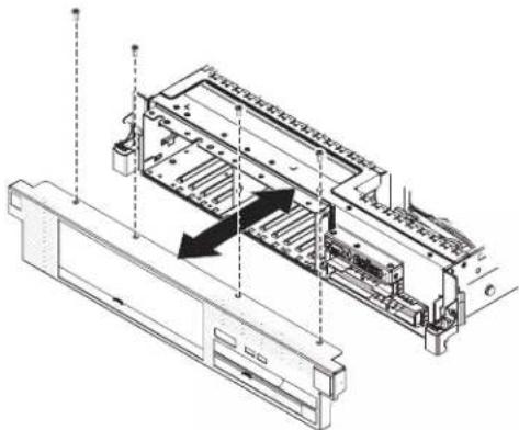
natural_image
Technical line drawing of a mechanical assembly with internal components and directional arrows (no text or symbols)a. Remove the screws from the bezel.
b. Rotate the top of the bezel away from the server and remove the tabs on the bottom of the bezel from the slots on the underside of the chassis.
- Move the hot-swap hard disk drives or fillers to the open drive bays:
a. Remove the hard disk drive or filler panel in drive bay 7 and replace it in bay 15. Slide the drive or filler panel most of the way into the drive bay, so that it is not fully seated.
b. One at a time, remove each remaining hard disk drive or filler panel and replace it in the rightmost available drive bay. Slide the drive or filler panel most of the way into the drive bay, so that it is not fully seated.
-
Disconnect all cables from the SAS hard disk drive backplanes and from the SAS riser-card. Set the SAS signal cables and the configuration cable aside; these cables will be replaced by the tape enablement kit cables.
-
Shift the SAS hard disk drive backplane to the right to create enough space to install a tape drive.
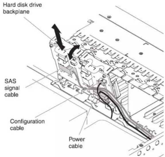
a. To obtain more working room, remove fans 2 and 3 (see "Removing a hot-swap fan" on page 115) and fan bracket.
b. Lift the backplane out of the server by pulling it toward the rear of the server and then lifting it up.
c. Move the backplane to the right backplane location.
- Install the EMC brackets in the chassis:
a. Install the right EMC bracket by sliding it into the front of the chassis until it locks into place.
b. Install the left EMC bracket by sliding it into the front of the chassis until it locks into place.

natural_image
Technical illustration showing two views of a mechanical assembly with arrows indicating assembly direction (no text or symbols present)c. Make sure that the open side of the bottom EMC bracket faces away from the server. To install the bottom EMC bracket, insert and tighten two M3 x 0.5 screws in the countersunk holes in the bottom bracket down into the chassis.
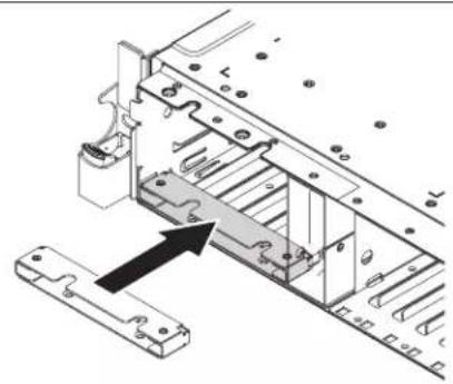
natural_image
Mechanical assembly diagram showing a bracket with mounting holes and a directional arrow indicating motion (no text or symbols present)
d. Make sure that the open side of the top EMC bracket faces away from the server. To install the top EMC bracket, insert and tighten two M3 x 0.5 screws in the threaded holes in the chassis down into the top bracket.
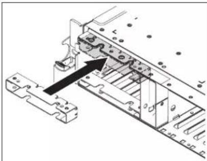
natural_image
Mechanical assembly diagram showing a component being inserted into a housing (no text or labels visible)
natural_image
Technical line drawing of a mechanical assembly with no visible text or symbols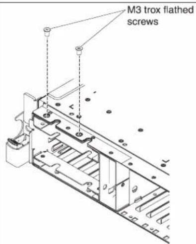
Installing the tape drive option
The following illustration shows how to install an optional tape drive.

To install a SATA or USB tape drive, complete the following steps:
-
Read the safety information that begins on page vii, "r"stallation guidelines" on page 37, and "Handling static-sensitive devices" on page 39.
-
Turn off the server and peripheral devices, and disconnect the power cords and all external cables.
-
Install the tape drive on the tray as shown in the following illustration. If the tape drive comes with a metal spacer attached, remove the spacer before you install the tape drive on the tray.
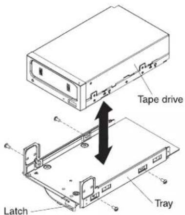
-
Prepare the drive according to the instructions that come with the drive, setting any switches or jumpers.
-
Remove the SAS riser-card and controller assembly (see "Removing the SAS riser-card and controller assembly" on page 117).
-
Remove the SAS controller from the SAS riser-card.
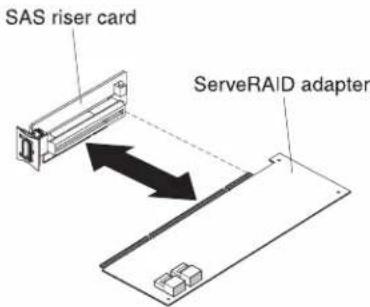
To remove the SAS controller from the SAS riser-card, complete the following steps:
a. Disconnect the SAS signal cables from the connectors on the SAS controller.
b. Pull the SAS controller horizontally out of the connector on the SAS riser-card.
- Remove the configuration cable and install the SAS controller on the tape-enabled SAS riser-card:

a. Disconnect and remove the configuration cable from the system board. This cable will be replaced by the tape-enabled configuration cable.
b. Turn the SAS controller so that the keys on the bottom edge align correctly with the connector on the tape-enabled SAS riser-card in the SAS riser-card and controller assembly.
c. Firmly press the SAS controller horizontally into the connector on the SAS riser-card.
d. Gently press the opposite edge of the SAS controller into the adapter retention bracket on the SAS riser-card and controller assembly.
Note: Depending on the height of your SAS controller, you might have to remove the retention bracket from the tape-enabled SAS riser-card and controller assembly, install the SAS controller and riser card on the SAS riser-card and controller assembly, and replace the retention bracket.
-
Connect the following tape enablement kit cables to the connectors on the SAS riser-card and the hard disk drive backplanes:
-
SAS signal cables into the SAS connectors on the hard disk drive backplanes
- SAS backplane power cable (that is connected to the system board) to the hard disk drive backplanes
-
Configuration cable to the configuration connector on each hard disk drive backplane
-
Connect the tape-enabled configuration cable to the system board.
-
Install the hard disk drive backplanes.
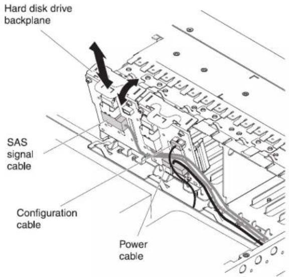
a. Align the backplane with the backplane slot in the chassis and the small slots on top of the hard disk drive cage.
b. Lower the backplane into the slots on the chassis.
c. Rotate the top of the backplane until the front tab clicks into place into the latches on the chassis.
d. Insert the hard disk drives or the filler panels the rest of the way into the hard disk drive bays.
- Make sure that the tape cables are connected securely to the following connectors on the SAS riser-card:
- Tape power cable: tape power connector
- Tape signal cable that came with the tape drive: SATA tape signal connector (SATA drive only) or USB tape connector (USB drive only)
The following illustration shows how to connect the SATA tape drive cables.
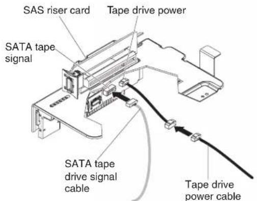
The following illustration shows how to connect the USB tape drive cables.

- Install the SAS riser-card and controller assembly (see "Installing the SAS riser-card and controller assembly" on page 118). Fold the excess length of the cables under the SAS controller assembly.
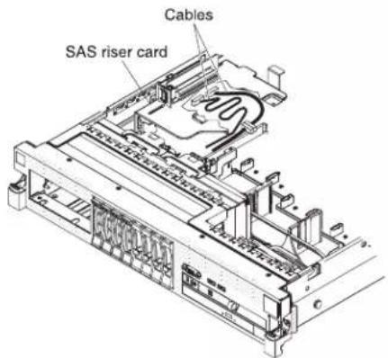
- Slide the tape-drive assembly most of the way into the tape-drive bay.
- Connect the signal and power cables from the SAS riser-card to the back of the tape drive.
Attention: Make sure that all the cables are positioned underneath the tape-drive assembly before you insert the assembly in the tape-drive bay. Otherwise, the cables might be damaged.
- Slide the tape-drive assembly the rest of the way into the tape-drive bay.
- Push the latch to the closed (locked) position.
If you have other devices to install or remove, do so now. Otherwise, go to "Completing the installation" on page 139.
Installing a second microprocessor
The following notes describe the type of microprocessor that the server supports and other information that you must consider when you install a microprocessor:
Important: Always use the microprocessor installation tool to install a microprocessor. Failing to use the microprocessor installation tool may damage the microprocessor sockets on the system board. Any damage to the microprocessor sockets may require replacing the system board.
- The server supports certain Intel Xeon scalable multi-core microprocessors, which are designed for the LGA 1366 socket. These microprocessors are 64-bit dual-core or quad-core microprocessors with an integrated memory controller, quick-path interconnect, and shared last cache. See http://www.ibm.com/servers/eserver/serverproven/compat/us/ for a list of supported microprocessors.
- The server supports up to two microprocessors. If the server comes with one microprocessor, you can install a second microprocessor.
- Do not install an Intel Xeon ^TM 5500 series microprocessor and an Intel Xeon ^TM 5600 series microprocessor in the same server.
- Both microprocessors must have the same QuickPath Interconnect (QPI) link speed, integrated memory controller frequency, core frequency, power segment, cache size, and type.
-
Read the documentation that comes with the microprocessor to determine whether you must update the server firmware for the server. To download the most current level of server firmware and many other code updates for your server, complete the following steps:
-
Go to http://www.ibm.com/systems/support/.
- Under Product support, click System x.
- Under Popular links, click Software and device drivers.
-
Click System x3650 M3 to display the matrix of downloadable files for the server.
-
(Optional) Obtain an SMP-capable operating system. For a list of supported operating systems and optional devices, see http://www.ibm.com/servers/eserver/serverproven/compat/us/.
- To order additional microprocessor optional devices, contact your IBM marketing representative or authorized reseller.
- The microprocessor speeds are automatically set for this server; therefore, you do not have to set any microprocessor frequency-selection jumpers or switches.
- If you have to replace a microprocessor, call for service.
- If the thermal-grease protective cover (for example, a plastic cap or tape liner) is removed from the heat sink, do not touch the thermal grease on the bottom of the heat sink or set down the heat sink.
- Do not remove the first microprocessor from the system board to install the second microprocessor.
The following illustration shows the microprocessor socket locations on the system board.
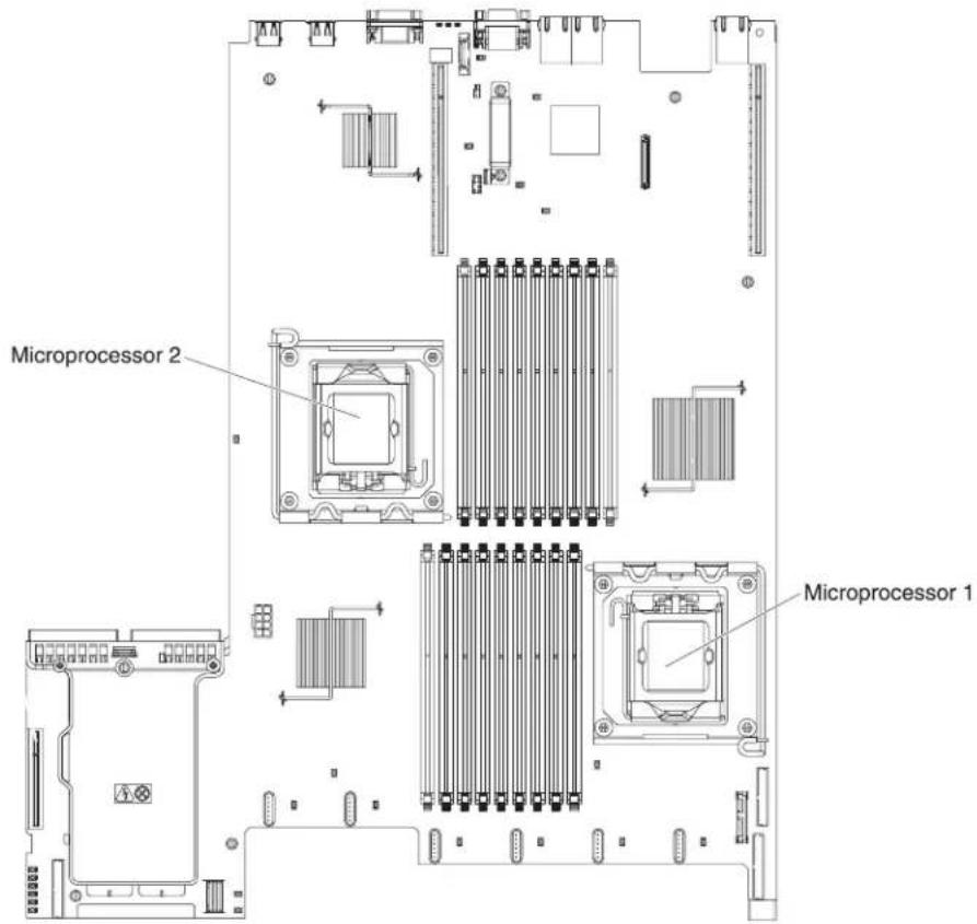
Attention:
- A startup (boot) microprocessor must always be installed in microprocessor socket 1 on the system board.
- To ensure correct server operation when you install an additional microprocessor, use microprocessors that are compatible and install at least one DIMM in a DIMM connector for microprocessor 2.
To install an additional microprocessor, complete the following steps:
- Read the safety information that begins on page vi and "Installation guidelines" on page 37.
- Turn off the server and disconnect all power cords and external cables (see "Turning off the server" on page 22).
- Remove the server cover (see "Removing the cover" on page 45).
- Remove PCI riser-card assembly 2 (see "Removing a PCI riser-card assembly" on page 46).
- Remove the microprocessor air baffle (see "Removing the microprocessor 2 air baffle" on page 48).
- Locate the second microprocessor socket on the system board.
-
Rotate the heat-sink release lever to the fully open position.
-
Install the microprocessor:
a. Rotate the microprocessor release lever on the socket from its closed and locked position until it stops in the fully open position.

b. Rotate the hinged microprocessor bracket frame into the open position.
c. Remove the microprocessor socket dust cover from the surface of the microprocessor socket, if one is present. Store the dust cover in a safe place.
d. Touch the static-protective package that contains the microprocessor to any unpainted metal surface on the server. Then, remove the microprocessor from the package.
Attention:
- Do not touch the microprocessor contacts; handle the microprocessor by the edges only. Contaminants on the microprocessor contacts, such as oil from your skin, can cause connection failures between the contacts and the socket.
- Handle the microprocessor carefully. Dropping the microprocessor during installation or removal can damage the contacts.
- Do not use excessive force when you press the microprocessor into the socket.
- Make sure that the microprocessor is oriented and aligned and positioned in the socket before you try to close the lever.

e. If there is a plastic protective cover on the bottom of the microprocessor, carefully remove it.
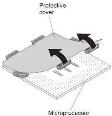
f. Locate the microprocessor installation tool that comes with the new microprocessor.
Note: The microprocessor installation tool assembly comes with the microprocessor and microprocessor cover attached to the tool. The microprocessor comes protected between the tool and the microprocessor cover.

g. Remove the microprocessor installation tool assembly from the package.
Note: Do not rotate the handle on the tool until you are ready to install the microprocessor into the microprocessor socket.
h. Remove the cover from the bottom of the microprocessor installation tool. Press both microprocessor cover release tabs outward (in opposite directions as shown in the illustration) and remove the microprocessor installation tool with the microprocessor attached.
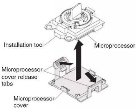
i. Carefully align the microprocessor installation tool over the microprocessor socket.
Attention: The microprocessor fits only one way on the socket. You must place a microprocessor straight down on the socket to avoid damaging the pins on the socket. The pins on the socket are fragile. Any damage to the pins may require replacing the system board.

j. Twist the handle on the microprocessor tool counterclockwise to insert the microprocessor into the socket.

k. Close the microprocessor bracket frame.
-
Carefully close the microprocessor release lever to the closed position to secure the microprocessor in the socket.
-
Install a heat sink on the microprocessor.
Attention: Do not touch the thermal grease on the bottom of the heat sink or set down the heat sink after you remove the plastic cover. Touching the thermal grease will contaminate it. If the thermal grease is contaminated, call IBM service and support to request a replacement thermal grease kit. For information about installing the replacement thermal grease, see "Thermal"
grease" on page 103.

a. Make sure that the heat-sink release lever is in the fully open position.
b. Remove the plastic protective cover from the bottom of the heat sink.
c. Align the heat sink above the microprocessor with the thermal-grease side down.
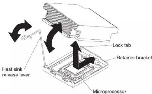
d. Slide the rear flange of the heat sink into the opening in the retainer bracket.
e. Press down firmly on the front of the heat sink until it is seated securely.
f. Rotate the heat-sink release lever to the closed position and hook it underneath the lock tab.
-
Install the microprocessor air baffle (see "Installing the microprocessor 2 air baffle" on page 49).
-
Install PCI riser-card assembly 2 (see "Installing a PCI riser-card assembly" on page 47).
If you have other devices to install or remove, do so now. Otherwise, go to "Completing the installation" on page 139.
Thermal grease
The thermal grease must be replaced whenever the heat sink has been removed from the top of the microprocessor and is going to be reused or when debris is found in the grease.
To replace damaged or contaminated thermal grease on the microprocessor and heat exchanger, complete the following steps:
- Place the heat-sink assembly on a clean work surface.
- Remove the cleaning pad from its package and unfold it completely.
- Use the cleaning pad to wipe the thermal grease from the bottom of the heat exchanger.
Note: Make sure that all of the thermal grease is removed.
- Use a clean area of the cleaning pad to wipe the thermal grease from the microprocessor; then, dispose of the cleaning pad after all of the thermal grease is removed.
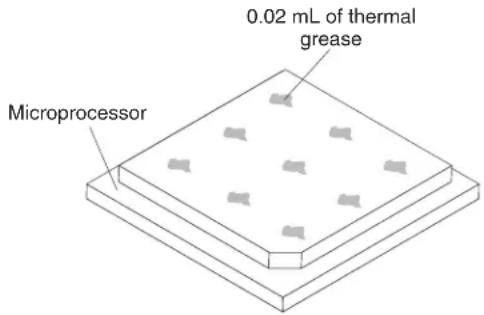
- Use the thermal-grease syringe to place nine uniformly spaced dots of 0.02 mL each on the top of the microprocessor.
Note: 0.01mL is one tick mark on the syringe. If the grease is properly applied, approximately half (0.22 mL) of the grease will remain in the syringe.
Installing a memory module
The following notes describe the types of dual inline memory modules (DIMMs) that the server supports and other information that you must consider when you install DIMMs.
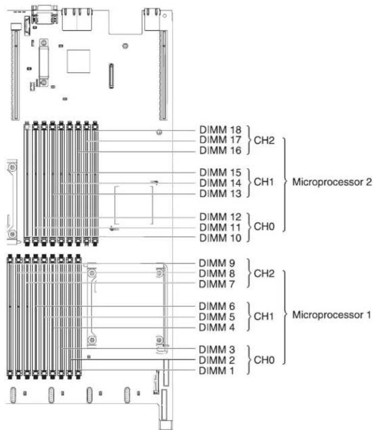
- When you install or remove DIMMs, the server configuration information changes. When you restart the server, the system displays a message that indicates that the memory configuration has changed.
- The server supports only industry-standard double-data-rate 3 (DDR3), 800, 1066, or 1333 MHz, PC3-10600R-999, registered or unbuffered, synchronous dynamic random-access memory (SDRAM) dual inline memory modules (DIMMs) with error correcting code (ECC). See http://www.ibm.com/servers/eserver/serverproven/compat/us/ for a list of supported memory modules for the server.
- The specifications of a DDR3 DIMM are on a label on the DIMM, in the following format.
ggg eRxff-PC3-wwwwww-m-aa-bb-cc
where:
ggg is the total capacity of the DIMM (for example, 1GB, 2GB, or 4GB)
e is the number of ranks
1 = single-rank
2 = dual-rank
4 = quad-rank
ff is the device organization (bit width)
4 = x4 organization (4 DQ lines per SDRAM)
8 = x8 organization
16 = x16 organization
www is the DIMM bandwidth, in MBps
6400 = 6.40 GBps (PC3-800 SDRAMs, 8-byte primary data bus)
8500 = 8.53 GBps (PC3-1066 SDRAMs, 8-byte primary data bus)
10600 = 10.66 GBps (PC3-1333 SDRAMs, 8-byte primary data bus)
12800 = 12.80 GBps PC3-1600 SDRAMs, 8-byte primary data bus)
m is the DIMM type
E = Unbuffered DIMM (UDIMM) with ECC (x72-bit module data bus)
R = Registered DIMM (RDIMM)
U = Unbuffered DIMM with no ECC (x64-bit primary data bus)
aa is the CAS latency, in clocks at maximum operating frequency bb is the JEDEC SPD Revision Encoding and Additions level cc is the reference design file for the design of the DIMM d is the revision number of the reference design of the DIMM
- The following rules apply to DDR3 DIMM speed as it relates to the number of DIMMs in a channel:
- When you install 1 DIMM per channel, the memory runs at 1333 MHz
- When you install 2 DIMMs per channel, the memory runs at 1066 MHz
- When you install 3 DIMMs per channel, the memory runs at 800 MHz
– All channels in a server run at the fastest common frequency.
- Do not install registered and unbuffered DIMMs in the same server.
- The maximum memory speed is determined by the combination of the microprocessor, DIMM speed, and the number of DIMMs installed in each channel.
- In two-DIMM-per-channel configuration, a server with an Intel Xeon X5600 series microprocessor automatically operates with a maximum memory speed of up to 1333 MHz when one of the following conditions is met:
- Two 1.5 V single-rank or dual-rank RDIMMs are installed in the same channel. In the Setup utility, Memory speed is set to Max performance mode
- Two 1.35 V single-rank or dual-ranl RDIMMs are installed in the same channel. In the Setup utility, Memory speed is set to Max performance and LV-DIMM power is set to Enhance performance mode. The 1.35 V RDIMMs will function at 1.5 V
- The server supports a maximum of 18 single-rank or dual-rank RDIMMs. The server supports up to 12 single-rank or dual-rank UDIMMs or quad-rank RDIMMs.
Note: To determine the type of a DIMM, see the label on the DIMM. The information on the label is in the format xxxx nRxxx PC3-xxxxxx-xx-xx-xxx. The numeral in the sixth numerical position indicates whether the DIMM is single-rank (n=1), dual-rank (n=2), or quad-rank (n=4).
- The server supports three single-rank or dual-rank DIMMs per channel. The server supports a maximum of two quad-rank RDIMMs per channel. The following table shows an example of the maximum amount of memory that you can install using ranked DIMMs:
Table 7. Maximum memory installation using ranked DIMMs
| Number of DIMMs DIMM type DIMM size Total memory | ||
| 12 Single-rank UDIMMs | 2 GB 24 GB | |
| 12 Dual-rank UDIMMs | 4 GB 48 GB | |
| 18 Single-rank RDIMMs | 2 GB 36 GB | |
| 18 Dual-rank RDIMMs | 2 GB 36 GB | |
| 18 Dual-rank RDIMMs | 4 GB 72 GB | |
| 18 Dual-rank RDIMMs | 8 GB 144 GB | |
| 12 Quad-rank RDIMMs | 16 GB 192 GB | |
| 18 Dual-rank RDIMMs | 16 GB 288 GB | |
- The RDIMM options that are available for the server are 2 GB, 4 GB, 8 GB, and 16 GB. The server supports a minimum of 2 GB and a maximum of 288 GB of system memory using RDIMMs.
For 32-bit operating systems only: Some memory is reserved for various system resources and is unavailable to the operating system. The amount of memory that is reserved for system resources depends on the operating system, the configuration of the server, and the configured PCI devices.
- The UDIMM options that are available for the server are 2 GB and 4 GB. The server supports a minimum of 2 GB and a maximum of 48 GB of system memory using UDIMMs.
Note: The amount of usable memory is reduced depending on the system configuration. A certain amount of memory must be reserved for system resources. To view the total amount of installed memory and the amount of configured memory, run the Setup utility. For additional information, see Chapter 3, "Configuring the server," on page 143.
- A minimum of one DIMM must be installed for each microprocessor. For example, you must install a minimum of two DIMMs if the server has two microprocessors installed. However, to improve system performance, install a minimum of three DIMMs for each microprocessor.
- DIMMs in the same system must be the same type (UDIMM or RDIMM) to ensure that the server will operate correctly.
- When you install one quad-rank RDIMM in a channel, install it in the DIMM connector furthest away from the microprocessor.
- Do not install one quad-rank RDIMM in one channel and three RDIMMs in another channel.
DIMM installation sequence
The server comes with a minimum of one 2 GB DIMM installed in slot 3. When you install additional DIMMs, install them in the order shown in the following table to optimize system performance. In non-mirroring mode, all three channels on the memory interface for each microprocessor can be populated in any order and have no matching requirements. When you install additional DIMMs, install them in the order shown in Table 8 on page 107, to maintain performance.
Important: If you have configured the server to use memory mirroring, do not use the order in [Table 8 on page 107] go to 'Memory mirroring' on page 107 and use the installation order shown there.
Table 8. DIMM installation sequence for non-mirroring (normal) mode
| Installed microprocessors DIMM connector population sequence | |
| Microprocessor socket 1 Install | the DIMMs in the following sequence: 3, 6, 9, 2, 5, 8, 1, 4, 7 |
| Microprocessor socket 2 Install | the DIMMs in the following sequence: 12, 15, 18, 11, 14, 17, 10, 13, 16 |
Memory mirroring
Memory-mirroring mode replicates and stores data on two pairs of DIMMs within two channels simultaneously. If a failure occurs, the memory controller switches from the primary pair of memory DIMMs to the backup pair of DIMMs. To enable memory mirroring through the Setup utility, select System Settings → Memory. For details about enabling memory mirroring, see "Using the Setup utility" on page 144. When you use the memory mirroring feature, consider the following information:
- When you use memory mirroring, you must install a pair of DIMMs at a time. One DIMM must be in channel 0, and the mirroring DIMM must be in the same connector in channel 1. The two DIMMs in each pair must be identical in size, type, rank (single, dual, or quad), and organization. They do not have to be identical in speed. The channels run at the speed of the slowest DIMM in any of the channels. See [Table 10 on page 109] for the DIMM connectors that are in each pair.
- Channel 2, DIMM connectors 7, 8, 9, 16, 17, and 18 are not used in memory-mirroring mode.
- The maximum available memory is reduced to half of the installed memory when memory mirroring is enabled. For example, if you install 64 GB of memory using RDIMMs, only 32 GB of addressable memory is available when you use memory mirroring.
The following diagram shows the memory channel interface layout with the DIMM installation sequence for mirroring mode. The numbers within the boxes indicate the DIMM population sequence in pairs within the channels, and the numbers next to the boxes indicate the DIMM connectors within the channels. For example, the following illustration shows the first pair of DIMMs (indicated by ones (1) inside the boxes) should be installed in DIMM connectors 1 on channel 0 and DIMM connector 2 on channel 1. DIMM connectors 3, 6, 9, 12, 15, and 18 on channel 2 are not used in memory-mirroring mode.
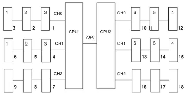
flowchart
graph TD
    subgraph CPU1
        A["1"] --> B["2"]
        B --> C["3"]
        C --> D["CH0"]
        D --> E["CPU1"]
        F["1"] --> G["2"]
        G --> H["3"]
        H --> I["CH1"]
        I --> J["CPU1"]
        K["9"] --> L["8"]
        L --> M["CH2"]
        M --> N["CPU1"]
    end

    subgraph CPU2
        O["CH0"] --> P["6"]
        P --> Q["5"]
        Q --> R["4"]
        R --> S["CPU2"]
        T["CH1"] --> U["6"]
        U --> V["5"]
        V --> W["4"]
        W --> X["CPU2"]
        Y["CH2"] --> Z["16"]
        Z --> AA["17"]
        AA --> AB["18"]

    style CPU1 fill:#f9f,stroke:#333
    style CPU2 fill:#ccf,stroke:#333
Figure 1. Memory channel interface layout
The following table lists the DIMM connectors on each memory channel.
Table 9. Connectors on each memory channel
| Memory channel DIMM connectors | |
| Channel 0 1, 2, 3, 10, 11, 12 | |
| Channel 1 4, 5, 6, 13, 14, 15 | |
| Channel 2 7, 8, 9, 16, 17, 18 |
The following illustration shows the memory connector layout that is associated with each microprocessor. For example, DIMM connectors 10, 11, 12, 13, 14, 15, 16, 17, and 18 (DIMM connectors are shown underneath the boxes) are associated with microprocessor 2 slot (CPU2) and DIMM connectors 1, 2, 3, 4, 5, 6, 7, 8, and 9 are associated with microprocessor 1 slot (CPU1). The numbers within the boxes indicates the installation sequence of the DIMM pairs. For example, the first DIMM pair (indicated within the boxes by ones (1)) should be installed in DIMM connectors 1 and 2, which is associated with microprocessor 1 (CPU1).
Note: You can install DIMMs for microprocessor 2 as soon as you install microprocessor 2; you do not have to wait until all of the DIMM connectors for microprocessor 1 are filled.
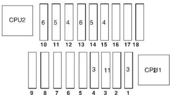
2
Figure 2. Memory connectors associated with each microprocessor
The following table lists the installation sequence for installing DIMMs in memory-mirroring mode.
Table 10. Memory-mirroring mode DIMM population sequence
| DIMMs | Number of installed microprocessors DIMM connector | |
| First pair of DIMMs 1 3, 6 | ||
| Second pair of DIMMs 1 2, 5 | ||
| Third pair of DIMMs 1 1, 4 | ||
| Fourth pair of DIMMs 2 12, 15 | ||
| Fifth pair of DIMMs 2 11, 14 | ||
| Sixth pair of DIMMs 2 10, 13 | ||
| Note: DIMM connectors 7, 8, 9, 16, 17, and 18 are not used in memory-mirroring mode. | ||
When you install or remove DIMMs, the server configuration information changes. When you restart the server, the system displays a message that indicates that the memory configuration has changed.
Online-spare memory
The server supports online-spare memory. This feature disables the failed memory from the system configuration and activates an online-spare DIMM to replace the failed active DIMM. You can enable either online-spare memory or memory mirroring in the Setup utility (see "Using the Setup utility" on page 144). When you use the memory online-spare feature, consider the following information:
- The memory online-spare feature is supported on server models with an Intel Xeon™ 5600 series microprocessor.
- When you enable the memory online-spare feature, you must install three DIMMs per microprocessor at a time. The first DIMM must be in channel 0, the second DIMM in channel 1, and the online-spare DIMM in channel 2. The DIMMs must be identical in size, type, rank, and organization, but not in speed. The channels run at the speed of the slowest DIMM in any of the channels.
- The maximum available memory is reduced to 2/3 of the installed memory when memory online-spare mode is enabled. For example, if you install 72 GB of memory using RDIMMs, only 48 GB of addressable memory is available when you use memory online-spare.
The following table shows the installation sequence for installing DIMMs for each microprocessor and the online-spare DIMM in memory online-spare mode:
Table 11. Memory online-spare mode DIMM population sequence
| Installed Microprocessor DIMM connector | |
| Microprocessor 1 3, 6, 9 | |
| 3, 6, 9, 2, 5, 8 | |
| 3, 6, 9, 2, 5, 8, 1, 4, 7 | |
| Microprocessor 2 12, 15, 18, | |
Installing a DIMM
To install a DIMM, complete the following steps.
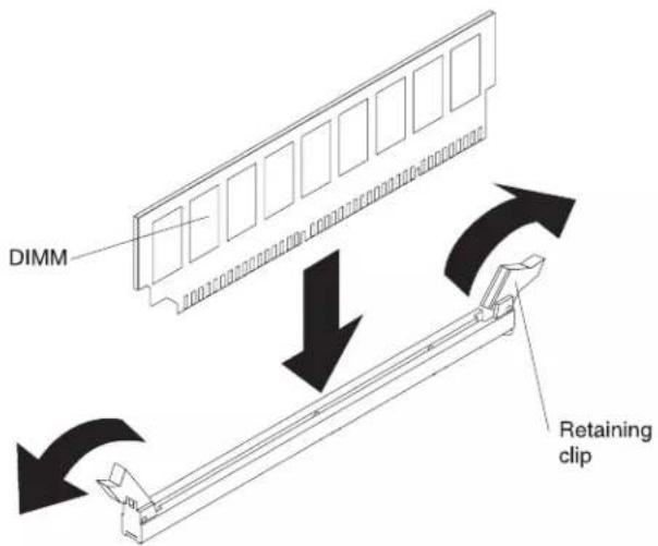
- Read the safety information that begins on page vii and "Installation guidelines" on page 37.
- Turn off the server and peripheral devices, and disconnect the power cord and all external cables (see "Turning off the server" on page 22)
- Remove the server cover (see "Removing the cover" on page 45).
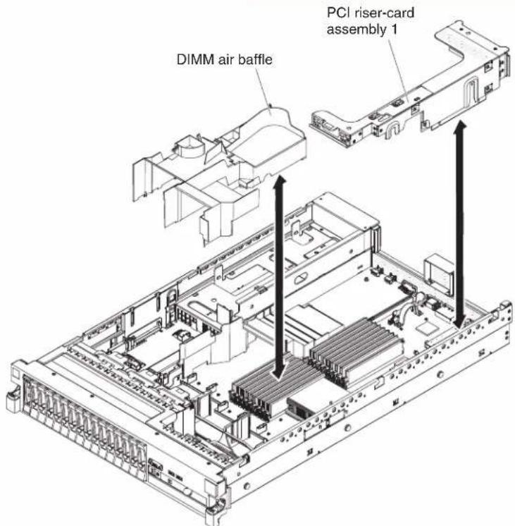
- If PCI riser-card assembly 1 contains one or more adapters, remove riser-card assembly 1 (see "Removing a PCI riser-card assembly" on page 46)
- Remove the DIMM air baffle (see "Removing the DIMM air baffle" on page 50).
Attention: To avoid breaking the retaining clips or damaging the DIMM connectors, open and close the clips gently.
- Open the retaining clip on each end of the DIMM connector.
- Touch the static-protective package that contains the DIMM to any unpainted metal surface on the server. Then, remove the DIMM from the package.
- Turn the DIMM so that the DIMM keys align correctly with the connector.
- Insert the DIMM into the connector by aligning the edges of the DIMM with the slots at the ends of the DIMM connector. Firmly press the DIMM straight down into the connector by applying pressure on both ends of the DIMM simultaneously. The retaining clips snap into the locked position when the DIMM is firmly seated in the connector.
Important: If there is a gap between the DIMM and the retaining clips, the DIMM has not been correctly inserted; open the retaining clips, remove the DIMM, and then reinsert it.
-
Install the DIMM air baffle (see "Installing the DIMM air baffle" on page 51).
-
Install PCI riser-card assembly 2, if you removed it (see "Installing a PCI riser-card assembly" on page 47).
If you have other devices to install or remove, do so now. Otherwise, go to "Completing the installation" on page 139. Go to the Setup utility and make sure all the installed DIMMs are present and enabled.
Installing a hot-swap ac power supply
The following notes describe the type of ac power supply that the server supports and other information that you must consider when you install a power supply:
- Make sure that the devices that you are installing are supported. For a list of supported optional devices for the server, see http://www.ibm.com/systems/info/x86servers/serverproven/compat/us/.
- Before you install an additional power supply or replace a power supply with one of a different wattage, you may use the IBM Power Configurator utility to determine current system power consumption. For more information and to download the utility, go to http://www-03.ibm.com/systems/bladecenter/resources/powerconfig.html.
- The server comes with one hot-swap 12-volt output power supply that connects to power supply bay 1. The input voltage is 110V ac or 220V ac auto-sensing.
- You cannot mix 460-watt and 675-watt power supplies, high-efficiency and non-high-efficiency power supplies, or ac and dc power supplies in the server.
- The following information applies when you install 460-watt power supplies in the server:
- A warning message is generated if the total power consumption exceeds 400 watts and the server only has one operational 460-watt power supply. In this case, the server can still operate under normal condition. Before you install additional components in the server, you must install an additional power supply
- The server automatically shuts down if the total power consumption exceeds the total power supply output capacity
- You can enable the power capping feature in the Setup utility to control and monitor power consumption in the server (see "Setup utility menu choices" on page 145)
The following table lists the system status when you install 460-watt power supplies in the server:
Table 12. System status with 460-watt power supplies installed
| Total system power consumption (in watts) | Number of 460-watt power supplies installed | ||
| One Two Two with one failure | |||
| < 400 Normal Normal, redundant | power | Normal | |
| 400 ~ 460 Normal, status warning | Normal, redundant power | Normal, status warning | |
| > 460 System shutdown | Normal System shutdown | ||
- Power supply 1 is the default/primary power supply. If power supply 1 fails, you must replace the power supply immediately.
- You can order an optional power supply for redundancy.
• These power supplies are designed for parallel operation. In the event of a power-supply failure, the redundant power supply continues to power the system. The server supports a maximum of two power supplies. - For instructions on how to install a hot-swap dc power supply, refer to the documentation that comes with the dc power supply.
Statement 5:

CAUTION:
The power control button on the device and the power switch on the power supply do not turn off the electrical current supplied to the device. The device also might have more than one power cord. To remove all electrical current from the device, ensure that all power cords are disconnected from the power source.
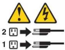
Statement 8:

CAUTION:
Never remove the cover on a power supply or any part that has the following label attached.

Hazardous voltage, current, and energy levels are present inside any component that has this label attached. There are no serviceable parts inside these components. If you suspect a problem with one of these parts, contact a service technician.

To install an ac power supply, complete the following steps:
-
Read the safety information that begins on page vii and "Installation guidelines" on page 37.
-
Remove the power-supply blank from the empty power-supply bay by pinching the side clip and pulling the power-supply blank from the bay. Save the power-supply blank in case you remove the power supply at a later time.
Important: During normal operation, each power-supply bay must contain either a power supply or power-supply blank for proper cooling.
- Slide the ac power supply into the bay until the retention latch clicks into place. Make sure that the power supply connects firmly into the power-supply connector.
Attention: Do not install 460-watt and 675-watt power supplies, high-efficiency and non-high-efficiency power supplies, or ac and dc power supplies in the server.
- Connect the power cord for the new ac power supply to the power-cord connector on the power supply.
The following illustration shows the ac power-supply connectors on the rear of the server.

-
Route the power cord through the power-supply handle and through any cable clamps on the rear of the server, to prevent the power cord from being accidentally pulled out when you slide the server in and out of the rack.
-
Connect the power cord to a properly grounded electrical outlet.
-
Make sure that the ac power LED and the dc power LED on the ac power supply are lit, indicating that the power supply is operating correctly. The two green LEDs are to the right of the power-cord connector.
-
If you are replacing a power supply with one of a different wattage, apply the power information label provided with the new power supply over the existing power information label on the server.
![额定电压 xxx-xxx/xxx-xxx 额定电流 x.x/x.x 额定频率 xx/xx HZ 额定电压 额定电流 额定频率 Manufactured for IBM Product certified to Shenzhen, China Media in China 中亚网络 © Copyright IBM Corp. 2018 All Rights Reserved. Copyright Code and Parts Confirmed Note. © Copyright IBM Corp. 2018 All Rights Reserved. © Copyright IBM Corp. 2018 All Rights Reserved. © Copyright IBM Corp. 2018 All Rights Reserved. © Copyright IBM Corp. 2018 All Rights Reserved. © Copyright IBM Corp. 2018 All Rights Reserved. © Copyright IBM Corp. 2018 All Rights Reserved. © Copyright IBM Corp. 2018 All Rights Reserved. © Copyright IBM Corp. 2018 All Rights Reserved. Appellation skull enables IR (iridial sitag Appellation via 3 packages perist atklantact Late on Ethernet upgen manufacturing software www.rsc.org.com/ This device comprises with part 15 of FCC rules. Operation is subject to the following two conditions: [1] this device may not cause harmful laserless, and [2] this device must offer any laserless received, including interference that may cause satellite operation. MOMI NOM NYSE N79 CE Canada ICS/NR/4000 Casa/Casia A EU Only L.T.E. Box: NEQ US U.S AR Model: no SR: 63000000000 MFC data: YYYTHOOD Product ID: PR.](/content/2026/06/1244538/images/b2189a4446d090fed4918a32fb06d47b570590e1e6f64829dbaf00b866f8aa47.jpg)
-
(IBM Business Partners only) Restart the server. Confirm that it starts correctly and recognizes the newly installed devices, and make sure that no error LEDs are lit.
-
(IBM Business Partners only) Complete the additional steps in "Instructions for IBM Business Partners" on page 25.
If you have other devices to install or remove, do so now. Otherwise, go to "Completing the installation" on page 139.
Removing a hot-swap fan
The server comes with three replaceable fans.
Attention: To ensure proper server operation and cooling, if you remove a fan with the system running, you must install a replacement fan within 30 seconds or the system will shut down.
To remove a replaceable fan, complete the following steps.

-
Read the safety information that begins on page 6 and "Installation guidelines" on page 37.
-
Leave the server connected to power.
-
Slide the server out of the rack and remove the cover (see "Removing the cover" on page 45). The LED near the failing fan will be lit.
Attention: To ensure proper system cooling, do not remove the top cover for more than 30 minutes during this procedure.
-
Lift the fan out of the server.
-
Replace the fan within 30 seconds (see "Installing a hot-swap fan" on page 116).
If you have other devices to install or remove, do so now. Otherwise, go to "Completing the installation" on page 139.
Installing a hot-swap fan
The server comes with three replaceable double fans. For proper cooling, the server requires that all three fans be installed at all times.
Attention: To ensure proper server operation, if a fan fails, replace it within 30 seconds. Have a replacement fan ready to install as soon as you remove the failed fan.
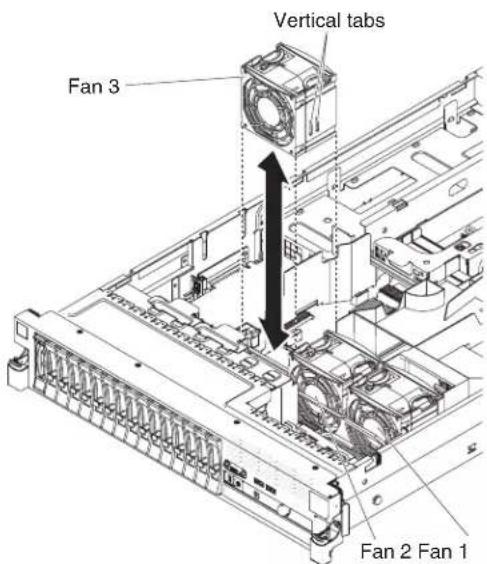
To install any of the three replaceable fans, complete the following steps:
-
Read the safety information that begins on page vi and "Installation guidelines" on page 37.
-
If you have not done so already, slide the server out of the rack and remove the cover (see "Removing the cover" on page 45).
Attention: To ensure proper system cooling, do not remove the top cover for more than 30 minutes during this procedure.
-
Orient the new fan over its position in the fan bracket so that the connector on the bottom aligns with the fan connector on the system board.
-
Align the vertical tabs on the fan with the slots on the fan cage bracket.
-
Push the new fan into the fan connector on the system board. Press down on the top surface of the fan to seat the fan fully. Make sure that the amber LED next to the fan connector on the system board is off.
If you have other devices to install or remove, do so now. Otherwise, go to "Completing the installation" on page 139.
Removing the SAS riser-card and controller assembly
To remove the SAS riser-card and controller assembly from the server, complete the steps for the applicable server model.
• 16-drive-capable server model:
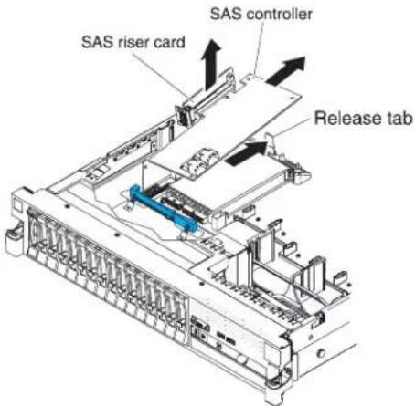
-
Press the assembly release latch toward the rear of the server and lift that end of the SAS controller assembly a little. Place your fingers underneath the upper portion of the SAS riser-card and lift the assembly from the system board.
-
Lift the assembly out of the server.
- Tape-enabled server model:

-
Press down on the assembly release latch and lift up on the tab to release the SAS controller assembly, which includes the SAS riser-card, from the system board.
-
Lift the front and back edges of the assembly to remove the assembly from the server.
Installing the SAS riser-card and controller assembly
To install the SAS riser-card and controller assembly in the server, complete the steps for the applicable server model.
• 16-drive-capable server model:
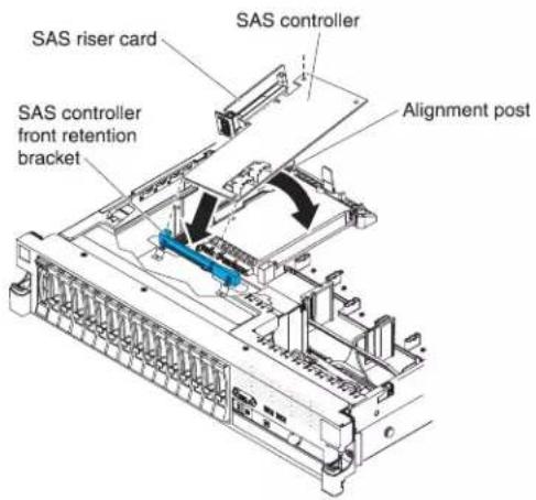
- If you are replacing a ServeRAID-BR10il v2 SAS/SATA controller with a ServeRAID-M5015/M5014 SAS/SATA controller, you have to swap the controller retention brackets to fit the new SAS controller.
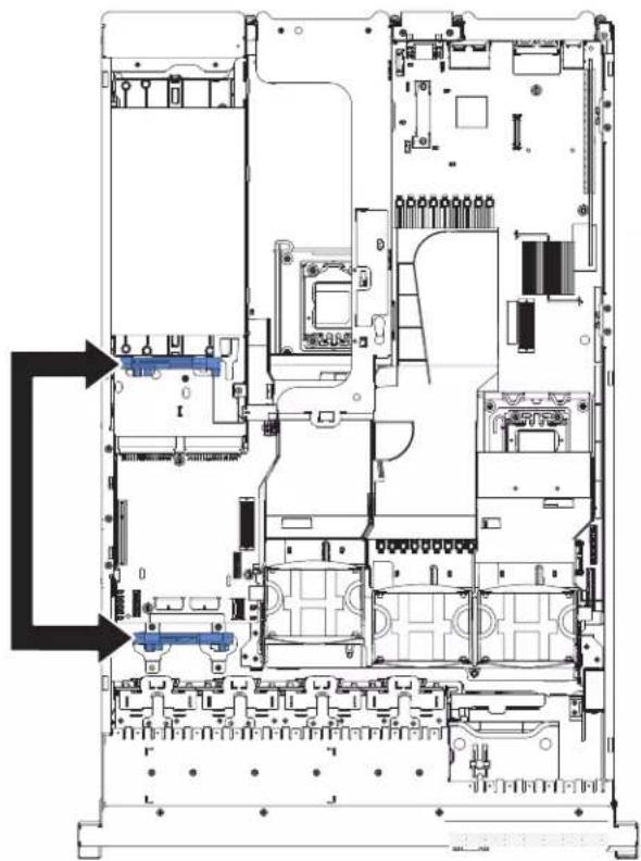
a. Remove the SAS controller front retention bracket from the server.
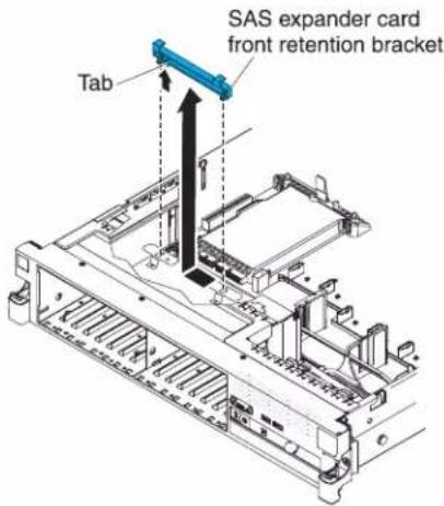
b. Remove the rear controller retention bracket located in the battery bay above the power supplies by pulling up the release tab 1 and sliding the bracket outward 2.
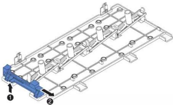
natural_image
Technical line drawing of a mechanical assembly with numbered components (no text or symbols)c. Install the controller retention bracket from step b by aligning the retention bracket controller slot and then placing the bracket tabs in the holes on the chassis and slide the bracket to left until it clicks into place.
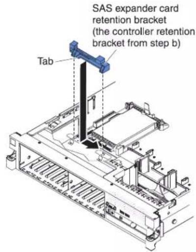
d. Install the controller retention bracket from step a by sliding the bracket inward 1 and pressing down the release tab into place 2.
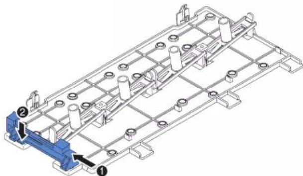
natural_image
Technical line drawing of a mechanical assembly with numbered components (no text or symbols)-
Place the front end of the SAS controller in the front retention bracket and align the SAS riser-card with the SAS riser-card connector on the system board.
-
Press down on the SAS riser-card and the rear edge of the SAS controller until the SAS riser-card is firmly seated and the SAS controller card retention latch clicks into place.
- Tape-enabled server model:
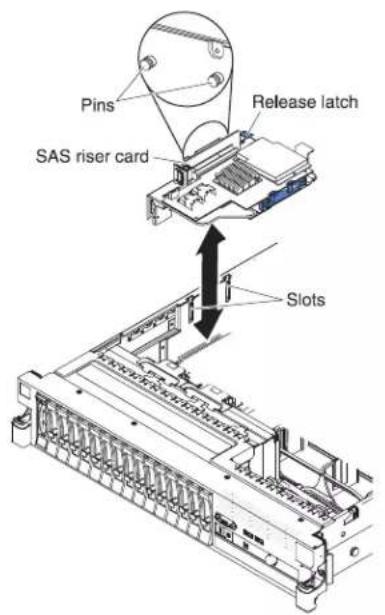
- Align the pins on the back side of the SAS riser-card with the slots on the server chassis.
- Make sure that any tape drive cables are routed correctly underneath the SAS riser-card. For information about the cable routing, see "nstalling an optional tape drive" on page 89.
- Press the SAS controller assembly into place. Make sure that the SAS riser-card is firmly seated and that the release latch and retention latch hold the assembly securely.
If you have other devices to install or remove, do so now. Otherwise, go to "Completing the installation" on page 139.
Removing a ServeRAID SAS controller from the SAS riser-card
A ServeRAID SAS controller is installed in a dedicated slot on the SAS riser-card.
Important: If you have installed a SAS expander card in a 16-drive-capable server, the SAS controller is installed in a PCI riser-card assembly and is installed and removed the same way as any other PCI adapter. Do not use the instructions in this topic; use the instructions in "Installing a PCI adapter" on page 53 and "Removing a PCI adapter" on page 57.
Depending on the server model, the server comes with a ServeRAID-BR10il v2 SAS/SATA controller or a ServeRAID-M1015 SAS/SATA controller installed.
You can replace the ServeRAID SAS controller with another supported ServeRAID SAS controller. For a list of supported ServeRAID SAS controllers, see http://www.ibm.com/servers/eserver/serverproven/compat/us.
Note: For brevity, in this documentation the ServeRAID SAS controller is often referred to as the SAS controller.
To remove the SAS controller from a SAS riser-card, complete the following steps:
-
Read the safety information that begins on page vi and "Installation guidelines" on page 37.
-
Turn off the server and peripheral devices and disconnect all power cords and external cables (see "Turning off the server" on page 22).
-
Remove the cover (see "Removing the cover" on page 45).
-
Locate the SAS riser-card and controller assembly near the left-front corner of the server.
-
Disconnect the SAS signal cables from the connectors on the SAS controller and note their locations.
-
Remove the SAS controller assembly, which includes the SAS riser-card, from the server (see "Removing the SAS riser-card and controller assembly" on page 117).
16-drive-capable server model:
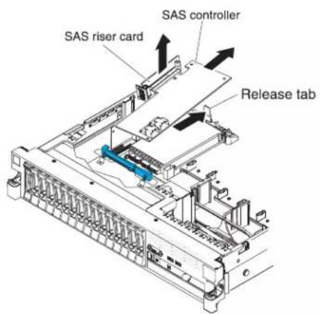
Tape-enabled server model:

- Pull the SAS controller horizontally out of the connector on the SAS riser-card.
Note: If you have installed the optional ServeRAID adapter advanced feature key, grasp the feature key and lift to remove it from connector on the ServeRAID adapter and keep it in future use.
- If you are replacing the SAS controller with another supported SAS controller, continue with "Installing a ServeRAID SAS controller on the SAS riser-card" on page 123.
Installing a ServeRAID SAS controller on the SAS riser-card
Important: If you have installed a SAS expander card in a 16-drive-capable server, the SAS controller is installed in a PCI riser-card assembly and is installed and removed the same way as any other PCI adapter. Do not use the instructions in this topic; use the instructions in "Installing a PCI adapter" on page 53 and "Removing a PCI adapter" on page 57.
To install a SAS controller on the SAS riser-card, complete the following steps:
- Make sure that the server is turned off, all external cables and power cords are disconnected, and the cover has been removed.
- If you are installing a new or replacement SAS controller, touch the static-protective package that contains the new SAS controller to any unpainted metal surface on the server. Then, remove the SAS controller from the package.
Note: If you have the optional ServeRAID adapter advanced feature key, install it first (see "Installing an optional ServeRAID adapter advanced feature key" on page 124).
- If you are installing a new or replacement SAS controller that uses a battery, complete the following steps:
a. Remove the battery from the SAS controller package or the battery package.
b. Install the battery and connect the battery to the SAS controller as instructed in the documentation that comes with the SAS controller or the battery.
-
If the new SAS controller is a different physical size than the SAS controller that you removed, you might have to move the controller retention bracket (tape-enabled model servers only) to the correct location for the new SAS controller. See "Moving the SAS controller retention bracket" on page 131; then, continue with the next step in this procedure.
-
Turn the SAS controller so that the connectors are facing up and the edge connectors are aligned correctly with the connector on the SAS riser-card.
16-drive-capable server model:
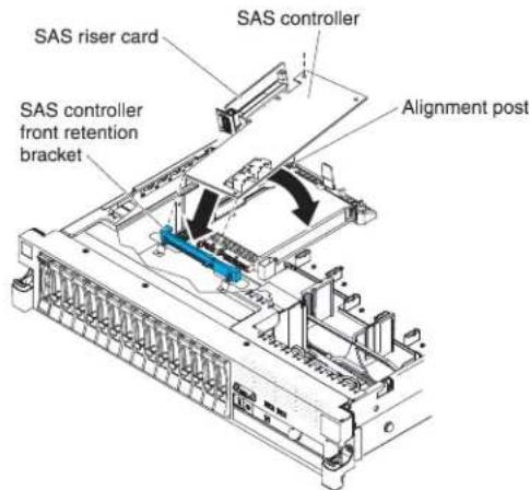
Tape-enabled server model:
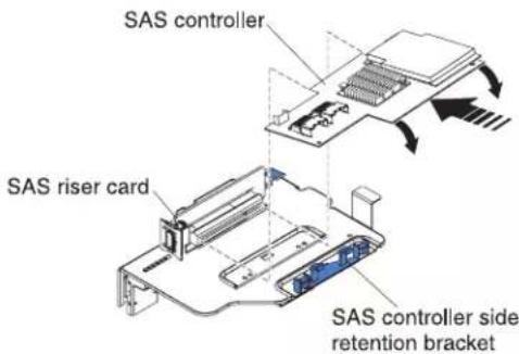
-
Firmly press the SAS controller horizontally into the connector on the SAS riser-card.
-
(Tape-enabled model server only) Gently press the opposite edge of the SAS controller into the controller retention bracket.
-
Install the SAS riser-card and controller assembly (see "Installing the SAS riser-card and controller assembly" on page 118).
If you have other devices to install or remove, do so now. Otherwise, go to "Completing the installation" on page 139.
Notes:
- When you restart the server for the first time after you install a SAS controller with a battery, the monitor screen remains blank while the controller initializes the battery. This might take a few minutes, after which the startup process continues. This is a one-time occurrence.
Important: You must allow the initialization process to be completed. If you do not, the battery pack will not work, and the server might not start.
The battery comes partially charged, at 30% or less of capacity. Run the server for 4 to 6 hours to fully charge the controller battery. The LED just above the battery on the controller remains lit until the battery is fully charged.
Until the battery is fully charged, the controller firmware sets the controller cache to write-through mode; after the battery is fully charged, the controller firmware re-enables write-back mode.
- When you restart the server, you are given the opportunity to import the existing RAID configuration to the new ServeRAID SAS controller.
Installing an optional ServeRAID adapter advanced feature key
To install an optional ServeRAID adapter advanced feature key, complete the following steps:
-
Read the safety information that begins on page vi and "Installation guidelines" on page 37.
-
Turn off the server and peripheral devices and disconnect all power cords and external cables (see "Turning off the server" on page 22).
-
Remove the cover (see "Removing the cover" on page 45).
-
Align the upgrade key with the connector on the ServeRAID adapter and push it into the connector until it is firmly seated.
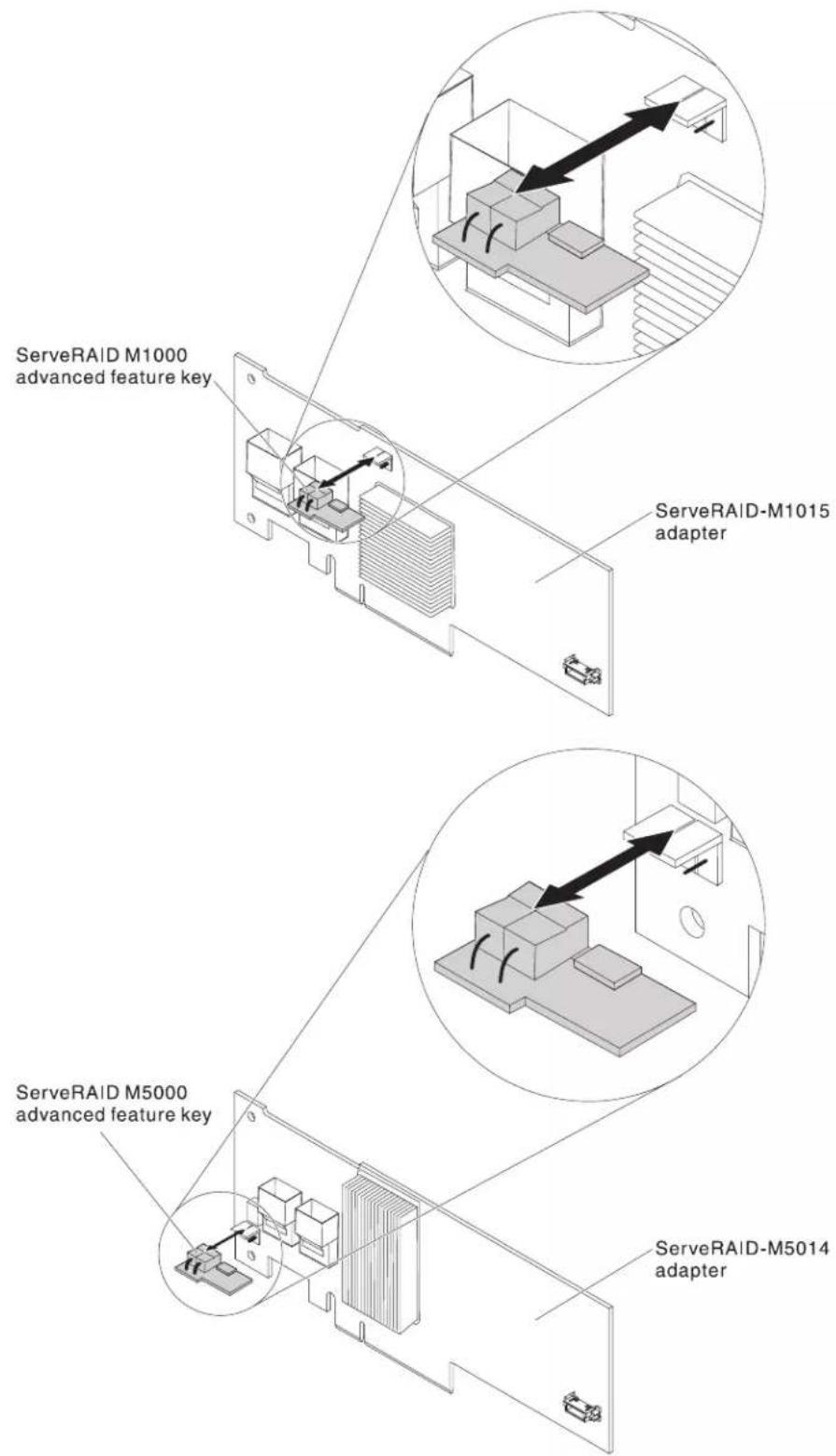
If you have other devices to install or remove, do so now. Otherwise, go to "Completing the installation" on page 139.
Installing a ServeRAID SAS controller battery on the remote battery tray
Note: For brevity, in this documentation the Intelligent Battery Backup Unit (iBBU) is often referred to as the battery.
When you install a ServeRAID SAS controller in a PCI riser-card assembly in the server, you must install the battery at a distance from the ServeRAID controller to avoid overheating. This section describes the process for installing a battery or batteries in the server.
To install a battery, complete the following steps:
- Read the safety information that begins on page vii and "Installation guidelines" on page 37.
- Turn off the server and peripheral devices and disconnect all power cords and external cables (see "Turning off the server" on page 22).
- Remove the cover (see "Removing the cover" on page 45).
- Remove the PCI riser-card assembly from the server and set it aside (see "Removing a PCI riser-card assembly" on page 46).
-
Remove the ServeRAID controller from the riser card (see "Removing a PCI adapter" on page 57).
-
If a battery and battery carrier are attached to the SAS controller, disconnect the battery carrier cable from the battery and remove the three screws that secure the battery carrier to the ServeRAID controller. Set the battery and battery carrier aside.
Note: The illustrations in this document might differ slightly from your hardware.

- Install the interposer card on the interposer card connector on the ServeRAID controller:
a. Remove the interposer card and the loose screw from the bag.
b. Rotate the standoff so that it aligns with the hole in the ServeRAID controller, and position the interposer card connector over the ServeRAID controller connector.

c. Press the interposer card down onto the interposer card connector so that the interposer card is secured.
d. From the other side of the ServeRAID controller, insert and tighten the screw to secure the interposer card to the ServeRAID controller.
- Connect one end of the remote battery cable to the interposer card.
Attention: To avoid damage to the hardware, make sure that you align the black dot on the cable connector with the black dot on the connector on the interposer card. Do not force the remote battery cable into the connector.

-
Install the ServeRAID controller on the riser card (see "Installing a PCI adapter" on page 53).
-
Install the PCI riser-card assembly in the server (see "Installing a PCI riser-card assembly" on page 47).
-
Connect the remote battery cable to the battery carrier.
Attention: To avoid damage to the hardware, make sure that you align the black dot on the cable connector with the black dot on the connector on the interposer card. Do not force the remote battery cable into the connector.
- Install the battery on the remote battery tray:
a. Connect the battery carrier cable to the battery, if it is not already connected.
b. On the remote battery tray, find the pattern of recessed rings that matches the posts on the battery and battery carrier.
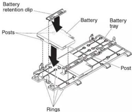
c. Press the posts into the rings and underneath the tabs on the remote battery tray.
d. Secure the battery to the tray with the battery retention clip.
- Route the remote battery cable.
Attention: Make sure that the cable is not pinched and does not cover any connectors or obstruct any components on the system board.

- For a battery that is installed in PCI assembly slot 1: Route the remote battery cable from the ServeRAID controller down through the slot on the left side of the DIMM air baffle, through the notch on the left side of the DIMM air baffle, across to the notch in the microprocessor air baffle, and up to the battery on the remote battery tray.
- For a battery that is installed in PCI assembly slot 2: Route the remote battery cable from the ServeRAID controller through the hole in the right side of the power supply (see the illustration detail).
- To install another ServeRAID controller remote battery in the server, repeat steps 7 on page 127 through 2 on page 129.
- Install the server cover.
- Connect the power cords and all external cables, and turn on the server and peripheral devices.
Note: The battery must recharge for at least 6 hours under normal operating conditions. To protect your data, the ServeRAID controller firmware changes the write policy to write-through until the battery unit is sufficiently charged. When the battery unit is charged, the ServeRAID controller firmware changes the write policy to write-back.
Moving the SAS controller retention bracket
Note: This procedure applies only to servers that have the following SAS riser-card.
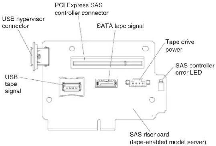
To move the SAS controller side retention bracket to a different position to accommodate the dimensions of the current SAS ServeRAID controller, complete the following steps:
-
Read the safety information that begins on page vi and "Installation guidelines" on page 37.
-
Make sure that the server and all peripheral devices are turned off and that the power cords and all external cables are disconnected.
-
Remove the SAS riser-card assembly from the server (see "Removing the SAS riser-card and controller assembly" on page 117).
-
Remove the ServeRAID controller from the SAS riser-card.
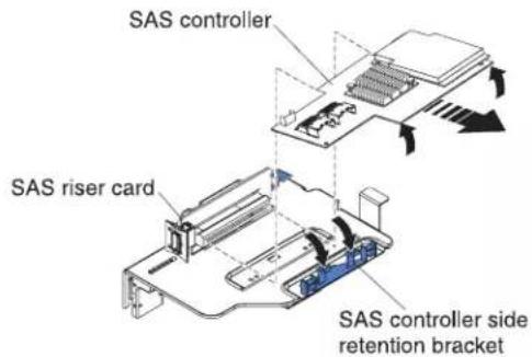
- Remove the retention bracket from the current location:
a. Pinch the bottoms of both bracket posts and push the posts up out of the SAS riser-card assembly.
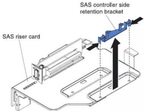
b. Rotate the bracket to free the bracket tab from the slot on the SAS riser-card assembly.
- Install the retention bracket in the new location on the SAS riser-card assembly:
a. Insert the bracket tab into the slot on the SAS riser-card assembly.

b. Rotate the bracket so that the bracket posts align with the holes in the SAS riser-card assembly.
c. Press the posts through the holes in the SAS riser-card until they click into place.
d. Install the SAS controller on the SAS riser-card (see "Installing a ServeRAID SAS controller on the SAS riser-card" on page 123).
e. Install the riser-card assembly in the server (see "Installing the SAS riser-card and controller assembly" on page 118).
f. Connect the power cords and all external cables, and turn on the server and peripheral devices.
Installing a USB hypervisor memory key
Hypervisor is a virtualization platform that enables multiple operating systems to run on a host computer at the same time. Support for hypervisor is available with the purchase and installation of an optional USB hypervisor memory key, with embedded hypervisor software.
To install the USB hypervisor memory key, complete the following steps:
- Read the safety information that begins on page vi and "Installation guidelines" on page 37.
- Turn off the server and peripheral devices and disconnect all power cords and external cables (see "Turning off the server" on page 22)
- Remove the cover (see "Removing the cover" on page 45).
- Locate the SAS riser-card assembly, which is near the left front corner of the server.
- Push the blue locking collar on the USB hypervisor connector on the SAS riser-card toward the SAS riser-card (the unlocked position).
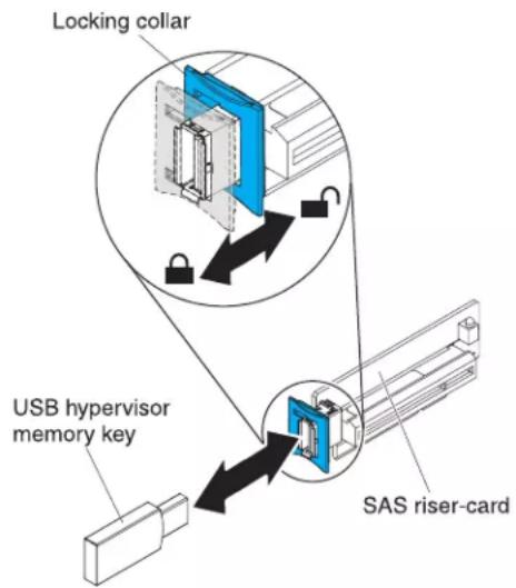
- Insert the hypervisor memory key into the USB hypervisor connector.
- Slide the blue lock on the USB hypervisor connector forward toward the hypervisor memory key as far as it will go, to secure the memory key in position.
If you have other devices to install or remove, do so now. Otherwise, go to "Completing the installation" on page 139.
Note: You must configure the server to boot from the hypervisor USB drive. See Chapter 3, "Configuring the server," on page 143 for information about enabling the embedded hypervisor.
Removing a USB hypervisor memory key
To remove the USB hypervisor memory key, complete the following steps:
- Read the safety information that begins on page 24 and "Installation guidelines" on page 37.
- Turn off the server and peripheral devices and disconnect all power cords and external cables (see "Turning off the server" on page 22).
- Remove the cover (see "Removing the cover" on page 45).
- Locate the SAS riser-card assembly, which is near the left front corner of the server.
- Push the blue locking collar on the USB hypervisor connector back toward the SAS riser-card to unlock it from the connector.
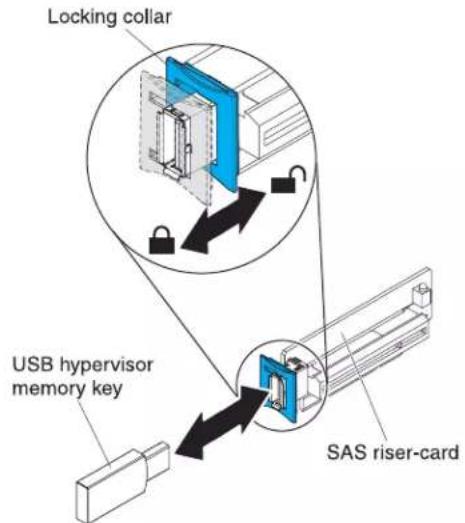
- Pull the hypervisor memory key from the USB hypervisor connector.
If you have other devices to install or remove, do so now. Otherwise, go to "Completing the installation" on page 139.
Note: You must configure the server not to look for the hypervisor USB drive. See Chapter 3, "Configuring the server," on page 143 for information about disabling hypervisor support.
Installing the optional two-port Ethernet adapter
To install an Ethernet adapter, complete the following steps:
- Read the safety information that begins on page vi and "Installation guidelines" on page 37.
-
Make sure that the server is turned off, all external cables and power cords are disconnected, and the cover has been removed. For more information, see "Turning off the server" on page 22 and "Removing the cover" on page 45.
-
Attach the rubber stopper on the chassis, along the edge of the system board, as shown in the following illustration.

- Remove the adapter filler panel on the rear of the chassis (if it has not been removed already).
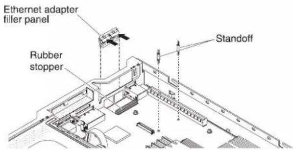
- Install the two standoffs on the system board.
- Insert the bottom tabs of the metal clip into the port openings from outside the chassis.

- While you slightly press the top of the metal clip, rotate the metal clip toward the front of the server until the metal clip clicks into place. Make sure the metal clip is securely engaged on the chassis.
Attention: Pressing the top of the metal clip with excessive force may cause damage to the metal clip.
-
Touch the static-protective package that contains the new adapter to any unpainted metal surface on the server. Then, remove the adapter from the package.
-
Align the adapter with the adapter connector on the system board; then, tilt the adapter so that the port connectors on the adapter line up with the port openings on the chassis.
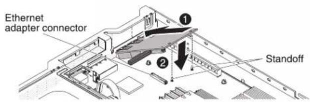
- Slide the port connectors on the adapter into the port openings on the chassis; then, press the adapter firmly until the two standoffs engage the adapter. Make sure the adapter is securely seated on the connector on the system board. Make sure the port connectors on the adapter do not set on the rubber stopper. The following illustration shows the side view of the adapter in the server.
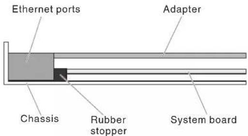
Attention: Make sure the port connectors on the adapter are aligned properly with the chassis on the rear of the server. An incorrectly seated adapter might cause damage to the system board or the adapter.

natural_image
Technical diagram showing two views of a server rack with internal components, no text or symbols present- Slide the port connectors on the adapter into the port openings on the chassis; then, press the adapter firmly until the two standoffs engage the adapter. Make sure the adapter is securely seated on the connector on the system board. Make sure the port connectors on the adapter do not set on the rubber stopper. The following illustration shows the side view of the adapter in the server.

Attention: Make sure the port connectors on the adapter are aligned properly with the chassis on the rear of the server. An incorrectly seated adapter might cause damage to the system board or the adapter.

natural_image
Technical diagram of a mechanical connector with internal channels, showing no text or symbols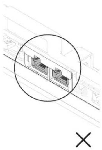
natural_image
Technical line drawing of a mechanical component with two internal slots, circled in black (no text or symbols)- Reinstall the PCI riser-card assembly in PCI riser connector 1 if you have removed it previously (see "Installing a PCI riser-card assembly" on page 47).
If you have other devices to install or remove, do so now. Otherwise, go to "Completing the installation" on page 139.
Installing an optional DVD drive
For a list of supported optional optical disk drives for the server, see http://www.ibm.com/servers/eserver/serverproven/compat/us/.
To install an optional DVD drive, complete the following steps.

- Read the safety information that begins on page vi and "Installation guidelines" on page 37.
- Make sure that the server is turned off, all external cables and power cords are disconnected, and the cover has been removed. For more information, see "Turning off the server" on page 22 and "Removing the cover" on page 45.
- Remove the optical drive filler panel if it is installed. Locate the blue release tab on the rear of the optical drive filler panel; then, while you press the tab, push the optical drive filler panel out of the drive bay. Save the optical drive filler panel for future use.

- Attach the drive-retention clip to the side of the drive.
- Slide the drive into the DVD drive bay until the drive clicks into place.
If you have other devices to install or remove, do so now. Otherwise, go to "Completing the installation."
Completing the installation
To complete the installation, complete the following steps:
- If you removed the microprocessor 2 air baffle, replace the microprocessor 2 air baffle (see "Installing the microprocessor 2 air baffle" on page 49).
- If you removed the DIMM air baffle, install it (see "Installing the DIMM air baffle" on page 51).
- If you removed either of the PCI riser-card assemblies, replace the riser-card assemblies (see "Installing a PCI riser-card assembly" on page 4/7).
- If you removed the server cover, replace it (see "Replacing the server cover" on page 140).
- Install the server in a rack. See the Rack Installation Instructions that come with the server for complete rack installation and removal instructions.
- To attach peripheral devices and connect the power cords, see "Connecting the external cables" on page 141.
Replacing the server cover
To replace the server cover, complete the following steps:
- Make sure that all internal cables are correctly routed.
- Place the cover-release latch in the open (up) position.

- Insert the bottom tabs of the top cover into the matching slots in the server chassis.
- Press down on the cover-release latch to slide the cover forward and lock the cover in place.
- Slide the server into the rack.
Connecting the external cables
The following illustrations show the locations of the input and output connectors on the front and rear of the server.
Front view
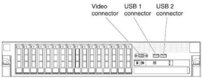
Rear view
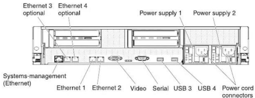
See the documentation that comes with any external devices for additional cabling instructions. It might be easier for you to route cables before you connect the devices to the server.
If the server comes with an installed operating system, see the documentation that comes with the operating system for additional cabling instructions.
Updating the server configuration
When you start the server for the first time after you add or remove an internal device, external SAS device, or USB keyboard or mouse, you might receive a message that the configuration has changed. After the POST fails three times, the Setup utility starts automatically so that you can save the new configuration settings. For more information, see Chapter 3, "Configuring the server," on page 143
Some optional devices have device drivers that you must install. See the documentation that comes with each optional device for information about installing device drivers.
The server comes with at least one multi-core microprocessor, which enables the server to operate as a symmetric multiprocessing (SMP) server. You might have to upgrade the operating system to support SMP. For more information, see “Using the ServerGuide Setup and Installation CD” on page 150 and the operating-system documentation.
If you have installed or removed a hard disk drive, see "Using the LSI Configuration Utility program" on page 157.
If you have installed a USB hypervisor memory key on the SAS riser-card, see the user's guide that comes with the hypervisor memory key. Hypervisor enables guest operating systems to function on the server.
For information about configuring the integrated Gigabit Ethernet controller, see "Configuring the Gigabit Ethernet controller" on page 156.
Chapter 3. Configuring the server
The following configuration programs come with the server:
- Setup utility
The Setup utility (formerly called the Configuration/Setup Utility program) is part of the IBM System x Server Firmware. Use it to change interrupt request (IRQ) settings, change the startup-device sequence, set the date and time, and set passwords. For information about using this program, see "Using the Setup utility" on page 144.
- Boot Menu program
The Boot Menu program is part of the IBM System x Server Firmware. Use it to override the startup sequence that is set in the Setup utility and temporarily assign a device to be first in the startup sequence.
• IBM ServerGuide Setup and Installation CD
The ServerGuide program provides software-setup tools and installation tools that are designed for the server. Use this CD during the installation of the server to configure basic hardware features, such as an integrated SAS controller with RAID capabilities, and to simplify the installation of your operating system. For information about obtaining and using this CD, see "Using the ServerGuide Setup and Installation CD" on page 150.
- Integrated management module
Use the integrated management module (IMM) for configuration, to update the firmware and sensor data record/field replaceable unit (SDR/FRU) data, and to remotely manage a network. For information about using the IMM, see "Using the integrated management module" on page 152.
- VMware embedded USB hypervisor
The VMware embedded USB hypervisor is available on the server models that come with an installed IBM USB Memory Key for VMware hypervisor. The USB memory key is installed in the USB connector on the SAS riser-card. Hypervisor is virtualization software that enables multiple operating systems to run on a host computer at the same time. For more information about using the embedded hypervisor, see "Using the USB memory key for VMware hypervisor" on page 153.
- Remote presence capability and blue-screen capture
The remote presence and blue-screen capture feature are integrated into the integrated management module (IMM). The virtual media key is required to enable these features. When the optional virtual media key is installed in the server, it activates the remote presence functions. Without the virtual media key, you will not be able to access the network remotely to mount or unmount drives or images on the client system. However, you will still be able to access the host graphical user interface through the Web interface without the virtual media key. You can order an optional IBM Virtual Media Key, if one did not come with your server. For more information about how to enable the remote presence function, see "Using the remote presence capability and blue-screen capture" on page 154.
- Ethernet controller configuration
For information about configuring the Ethernet controller, see "Configuring the Gigabit Ethernet controller" on page 156.
• LSI Configuration Utility program
Use the LSI Configuration Utility program to configure the integrated SAS/SATA controller with RAID capabilities and the devices that are attached to it. For information about using this program, see "Using the LSI Configuration Utility program" on page 157.
The following table lists the different server configurations and the applications that are available for configuring and managing RAID arrays.
Table 13. Server configuration and applications for configuring and managing RAID arrays
| Server configuration | RAID array configuration (before operating system is installed) | RAID array management (after operating system is installed) |
| ServeRAID-BR10i adapter (LSI 1068E) | LSI Utility (Setup utility, press Ctrl+C), ServerGuide | MegaRAID Storage Manager (for monitoring storage only) |
| ServeRAID-BR10il v2 adapter (LSI 1064E) | LSI Utility (Setup utility, press Ctrl+C), ServerGuide | MegaRAID Storage Manager and IBM Director |
| ServeRAID-MR10i adapter (LSI 1078) | MegaRAID Storage Manager (MSM), MegaRAID BIOS Configuration Utility (press C to start), ServerGuide | MegaRAID Storage Manager (MSM) |
| ServeRAID-M5014 adapter (LSI SAS2108) | MegaRAID Storage Manager (MSM), MegaCLI (Command Line Interface), ServerGuide | MegaRAID Storage Manager and IBM Director |
| ServeRAID-M5015 adapter (LSI SAS2108) | MegaRAID Storage Manager (MSM), MegaCLI (Command Line Interface), ServerGuide | MegaRAID Storage Manager and IBM Director |
| ServeRAID-M1050 adapter (LSI SAS2008) | MegaRAID Storage Manager (MSM), MegaCLI (Command Line Interface), ServerGuide | MegaRAID Storage Manager and IBM Director |
• IBM Advanced Settings Utility (ASU) program
Use this program as an alternative to the Setup utility for modifying UEFI settings and IMM settings. Use the ASU program online or out-of-band to modify UEFI settings from the command line without the need to restart the server to access the Setup utility. For more information about using this program, see "IBM Advanced Settings Utility program" on page 159.
Using the Setup utility
Use the Setup utility, formerly called the Configuration/Setup Utility program, to perform the following tasks:
• View configuration information
• View and change assignments for devices and I/O ports
- Set the date and time
- Set the startup characteristics of the server and the order of startup devices
- Set and change settings for advanced hardware features
• View, set, and change settings for power-management features
• View and clear error logs
- Resolve configuration conflicts
Starting the Setup utility
To start the Setup utility, complete the following steps:
- Turn on the server.
Note: Approximately 3 minutes after the server is connected to ac power, the power-control button becomes active.
-
When the prompt
Setupis displayed, press F1. If you have set an administrator password, you must type the administrator password to access the full Setup utility menu. If you do not type the administrator password, a limited Setup utility menu is available. -
Select the settings to view or change.
Setup utility menu choices
The following choices are on the Setup utility main menu. Depending on the version of the firmware, some menu choices might differ slightly from these descriptions.
- System Information
Select this choice to view information about the server. When you make changes through other choices in the Setup utility, some of those changes are reflected in the system information; you cannot change settings directly in the system information.
This choice is on the full Setup utility menu only.
– System Summary
Select this choice to view configuration information, including the ID, speed, and cache size of the microprocessors, machine type and model of the server, the serial number, the system UUID, and the amount of installed memory. When you make configuration changes through other choices in the Setup utility, the changes are reflected in the system summary; you cannot change settings directly in the system summary.
- Product Data
Select this choice to view the system-board identifier, the revision level or issue date of the firmware, the integrated management module and diagnostics code, and the version and date.
- System Settings
Select this choice to view or change the server component settings.
- Processors
Select this choice to view or change the processor settings.
- Memory
Select this choice to view or change the memory settings. To configure memory mirroring, select System Settings → Memory, and then select Memory Channel Mode → Mirroring.
– Devices and I/O Ports
Select this choice to view or change assignments for devices and input/output (I/O) ports. You can configure the serial ports; configure remote console redirection; enable or disable integrated Ethernet controllers, the SAS/SATA controller, SATA optical drive channels, and PCI slots; and video controller. If you disable a device, it cannot be configured, and the operating system will not be able to detect it (this is equivalent to disconnecting the device).
- Power
Select this choice to view or change power capping to control consumption, processors, and performance states.
- Operating Modes
Select this choice to view or change the operating profile (for example, performance and power utilization).
- Legacy Support
Select this choice to view or set legacy support.
- Force Legacy Video on Boot
Select this choice to force INT video support, if the operating system does not support UEFI video output standards.
- Rehook INT
Select this choice to enable or disable devices from taking control of the boot process. The default is Disable.
- Legacy Thunk Support
Select this choice to enable or disable the UEFI to interact with PCI mass storage devices that are not UEFI-compliant.
– Integrated Management Module
Select this choice to view or change the settings for the integrated management module.
- POST Watchdog Timer
Select this choice to view or enable the POST watchdog timer.
- POST Watchdog Timer Value
Select this choice to view or set the POST loader watchdog timer value.
- Reboot System on NMI
Enable or disable restarting the system whenever a nonmaskable interrupt (NMI) occurs. Disabled is the default.
- Commands on USB Interface Preference
Select this choice to enable or disable the Ethernet over USB interface on IMM.
- Network Configuration
Select this choice to view the system management network interface port, the IMM MAC address, the current IMM IP address, and host name; define the static IMM IP address, subnet mask, and gateway address; specify whether to use the static IP address or have DHCP assign the IMM IP address; save the network changes; and reset the IMM.
- Reset IMM to Defaults
Select this choice to view or reset IMM to the default settings.
- Reset IMM
Select this choice to reset IMM.
- Adapters and UEFI Drivers
Select this choice to view information about the adapters and drivers in the server that are compliant with EFI 1.10 and UEFI 2.0.
- Network
Select this choice to view or configure the network options, such as the iSCSI, PXE, and network devices. There might be additional configuration choices for optional network devices that are compliant with UEFI 2.1 and later.
- Storage
Select this choice to view or configure the storage devices options. There might be additional configuration choices for optional storage devices that are compliant with UEFI 2.1 and later.
• Video
Select this choice to view or configure the video device options installed in the server. There might be additional configuration choices for optional video devices that are compliant with UEFI 2.1 and later.
- Date and Time
Select this choice to set the date and time in the server, in 24-hour format (hour:minute:second).
This choice is on the full Setup utility menu only.
- Start Options
Select this choice to view or change the start options, including the startup sequence, keyboard NumLock state, PXE boot option, and PCI device boot priority. Changes in the startup options take effect when you start the server.
The startup sequence specifies the order in which the server checks devices to find a boot record. The server starts from the first boot record that it finds. If the server has Wake on LAN hardware and software and the operating system supports Wake on LAN functions, you can specify a startup sequence for the Wake on LAN functions. For example, you can define a startup sequence that checks for a disc in the CD-RW/DVD drive, then checks the hard disk drive, and then checks a network adapter.
This choice is on the full Setup utility menu only.
- Boot Manager
Select this choice to view, add, or change the device boot priority, boot from a file, select a one-time boot, or reset the boot order to the default setting.
- System Event Logs
Select this choice to enter the System Event Manager, where you can view the error messages in the system-event logs. You can use the arrow keys to move between pages in the error log.
The system-event logs contain all event and error messages that have been generated during POST, by the systems-management interface handler, and by the system service processor. Run the diagnostic programs to get more information about error codes that occur. See the Problem Determination and Service Guide on the IBM Documentation CD for instructions for running the diagnostic programs.
Important: If the system-error LED on the front of the server is lit but there are no other error indications, clear the system-event log. Also, after you complete a repair or correct an error, clear the system-event log to turn off the system-error LED on the front of the server.
- POST Event Viewer
Select this choice to enter the POST event viewer to view the error messages in the POST event log.
- System Event Log
Select this choice to view the error messages in the system-event log.
– Clear System Event Log
Select this choice to clear the system-event log.
- User Security
Select this choice to set, change, or clear passwords. See "Passwords" on page 148 for more information.
This choice is on the full and limited Setup utility menu.
- Set Power-on Password
Select this choice to set or change a power-on password. For more information, see "Power-on password" on page 149.
– Clear Power-on Password
Select this choice to clear a power-on password. For more information, see "Power-on password" on page 149.
- Set Administrator Password
Select this choice to set or change an administrator password. An administrator password is intended to be used by a system administrator; it limits access to the full Setup utility menu. If an administrator password is set, the full Setup utility menu is available only if you type the administrator password at the password prompt. For more information, see “Administrator password” on page 149.
– Clear Administrator Password
Select this choice to clear an administrator password. For more information, see "Administrator password" on page 149.
- Save Settings
Select this choice to save the changes that you have made in the settings.
- Restore Settings
Select this choice to cancel the changes that you have made in the settings and restore the previous settings.
- Load Default Settings
Select this choice to cancel the changes that you have made in the settings and restore the factory settings.
- Exit Setup
Select this choice to exit from the Setup utility. If you have not saved the changes that you have made in the settings, you are asked whether you want to save the changes or exit without saving them.
Passwords
From the User Security menu choice, you can set, change, and delete a power-on password and an administrator password. The User Security choice is on the full Setup utility menu only.
If you set only a power-on password, you must type the power-on password to complete the system startup and to have access to the full Setup utility menu.
An administrator password is intended to be used by a system administrator; it limits access to the full Setup utility menu. If you set only an administrator password, you do not have to type a password to complete the system startup, but you must type the administrator password to access the Setup utility menu.
If you set a power-on password for a user and an administrator password for a system administrator, you must type the power-on password to complete the system startup. A system administrator who types the administrator password has access to the full Setup utility menu; the system administrator can give the user authority to set, change, and delete the power-on password. A user who types the power-on password has access to only the limited Setup utility menu; the user can set, change, and delete the power-on password, if the system administrator has given the user that authority.
Power-on password
If a power-on password is set, when you turn on the server, the system startup will not be completed until you type the power-on password. You can use any combination of between six and 20 printable ASCII characters for the password.
When a power-on password is set, you can enable the Unattended Start mode, in which the keyboard and mouse remain locked but the operating system can start. You can unlock the keyboard and mouse by typing the power-on password.
If you forget the power-on password, you can regain access to the server in any of the following ways:
- If an administrator password is set, type the administrator password at the password prompt. Start the Setup utility and reset the power-on password.
- Remove the battery from the server and then reinstall it. See the Problem Determination and Service Guide on the IBM Documentation CD for instructions for removing the battery.
- Change the position of the power-on password switch (enable switch 1 of the system board switch block (SW4) to bypass the power-on password check (see "System-board switches and jumpers" on page 30 for more information).
Attention: Before you change any switch settings or move any jumpers, turn off the server; then, disconnect all power cords and external cables. See the safety information that begins on page "Safety" on page vii. Do not change settings or move jumpers on any system-board switch or jumper blocks that are not shown in this document.
The default for all of the switches on switch block (SW4) is Off.
While the server is turned off, move switch 1 of the switch block (SW4) to the On position to enable the power-on password override. You can then start the Setup utility and reset the power-on password. You do not have to return the switch to the previous position.
The power-on password override switch does not affect the administrator password.
Administrator password
If an administrator password is set, you must type the administrator password for access to the full Setup utility menu. You can use any combination of between six and 20 printable ASCII characters for the password.
Attention: If you set an administrator password and then forget it, there is no way to change, override, or remove it. You must replace the system board.
Using the Boot Selection Menu program
The Boot Selection Menu is used to temporarily redefine the first startup device without changing boot options or settings in the Setup utility.
To use the Boot Selection Menu program, complete the following steps:
- Turn off the server.
- Restart the server.
- Press F12 (Select Boot Device). If a bootable USB mass storage device is installed, a submenu item (USB Key/Disk) is displayed.
- Use the Up Arrow and Down Arrow keys to select an item from the Boot Selection Menu and press Enter.
The next time the server starts, it returns to the startup sequence that is set in the Setup utility.
Starting the backup server firmware
The system board contains a backup copy area for the server firmware. This is a secondary copy of server firmware that you update only during the process of updating server firmware. If the primary copy of the server firmware becomes damaged, use this backup copy.
To force the server to start from the backup copy, turn off the server; then, place the UEFI boot recovery J29 jumper in the backup position (pins 2 and 3).
Use the backup copy of the server firmware until the primary copy is restored. After the primary copy is restored, turn off the server; then, move the UEFI boot recovery J29 jumper back to the primary position (pins 1 and 2).
Using the ServerGuide Setup and Installation CD
The ServerGuide Setup and Installation CD contains a setup and installation program that is designed for your server. The ServerGuide program detects the server model and optional hardware devices that are installed and uses that information during setup to configure the hardware. The ServerGuide program simplifies operating-system installations by providing updated device drivers and, in some cases, installing them automatically.
You can download a free image of the ServerGuide Setup and Installation CD or purchase the CD from the ServerGuide fulfillment Web site at http://www.ibm.com/systems/management/serverguide/sub.htm. To download the free image, click IBM Service and Support Site.
Note: Changes are made periodically to the IBM Web site. The actual procedure might vary slightly from what is described in this document.
The ServerGuide program has the following features:
- An easy-to-use interface
- Diskette-free setup, and configuration programs that are based on detected hardware
- ServeRAID Manager program, which configures your ServeRAID adapter or integrated SCSI controller with RAID capabilities
- Device drivers that are provided for the server model and detected hardware
- Operating-system partition size and file-system type that are selectable during setup
ServerGuide features
Features and functions can vary slightly with different versions of the ServerGuide program. To learn more about the version that you have, start the ServerGuide Setup and Installation CD and view the online overview. Not all features are supported on all server models.
The ServerGuide program requires a supported IBM server with an enabled startable (bootable) CD drive. In addition to the ServerGuide Setup and Installation CD, you must have your operating-system CD to install the operating system.
The ServerGuide program performs the following tasks:
- Sets system date and time
- Detects the RAID adapter or controller and runs the SAS RAID configuration program (with LSI chip sets for ServeRAID adapters only)
- Checks the microcode (firmware) levels of a ServeRAID adapter and determines whether a later level is available from the CD
- Detects installed optional hardware devices and provides updated device drivers for most adapters and devices
- Provides diskette-free installation for supported Windows operating systems
- Includes an online readme file with links to tips for hardware and operating-system installation
Setup and configuration overview
When you use the ServerGuide Setup and Installation CD, you do not need setup diskettes. You can use the CD to configure any supported IBM server model. The setup program provides a list of tasks that are required to set up your server model. On a server with a ServeRAID adapter or integrated SCSI controller with RAID capabilities, you can run the SCSI RAID configuration program to create logical drives.
Note: Features and functions can vary slightly with different versions of the ServerGuide program.
When you start the ServerGuide Setup and Installation CD, the program prompts you to complete the following tasks:
- Select your language.
- Select your keyboard layout and country.
- View the overview to learn about ServerGuide features.
- View the readme file to review installation tips for your operating system and adapter.
- Start the operating-system installation. You will need your operating-system CD.
Important: Before you install a legacy operating system (such as VMware) on a server with an LSI SAS controller, you must first complete the following steps:
- Update the device driver for the LSI SAS controller to the latest level.
- In the Setup utility, set Legacy Only as the first option in the boot sequence in the Boot Manager menu.
- Using the LSI Configuration Utility program, select a boot drive.
For detailed information and instructions, go to https://www-947.ibm.com/systems/support/supportsite.wss/docdisplay?Indocid=MIGH-5083225.
Typical operating-system installation
The ServerGuide program can reduce the time it takes to install an operating system. It provides the device drivers that are required for your hardware and for the operating system that you are installing. This section describes a typical ServerGuide operating-system installation.
Note: Features and functions can vary slightly with different versions of the ServerGuide program.
-
After you have completed the setup process, the operating-system installation program starts. (You will need your operating-system CD to complete the installation.)
-
The ServerGuide program stores information about the server model, service processor, hard disk drive controllers, and network adapters. Then, the program checks the CD for newer device drivers. This information is stored and then passed to the operating-system installation program.
- The ServerGuide program presents operating-system partition options that are based on your operating-system selection and the installed hard disk drives.
- The ServerGuide program prompts you to insert your operating-system CD and restart the server. At this point, the installation program for the operating system takes control to complete the installation.
Installing your operating system without using ServerGuide
If you have already configured the server hardware and you are not using the ServerGuide program to install your operating system, complete the following steps to download the latest operating-system installation instructions from the IBM Web site.
Note: Changes are made periodically to the IBM Web site. The actual procedure might vary slightly from what is described in this document.
- Go to http://www.ibm.com/systems/support/.
- Under Product support, click System x.
- From the menu on the left side of the page, click System x support search.
- From the Task menu, select Install.
- From the Product family menu, select System x3650 M3.
- From the Operating system menu, select your operating system, and then click Search to display the available installation documents.
Using the integrated management module
The integrated management module (IMM) is a second generation of the functions that were formerly provided by the baseboard management controller hardware. It combines service processor functions, video controller, and (when an optional virtual media key is installed) remote presence function in a single chip.
The IMM supports the following basic systems-management features:
- Environmental monitor with fan speed control for temperature, voltages, fan failure, and power supply failure.
- Light path diagnostics LEDs to report errors that occur with fans, power supplies, microprocessor, hard disk drives, and system errors.
- DIMM error assistance. The Unified Extensible Firmware Interface (UEFI) disables a failing DIMM that is detected during POST, and the IMM lights the associated system-error LED and the failing DIMM error LED.
- System-event log.
- ROM-based IMM firmware flash updates.
• Auto Boot Failure Recovery. - A virtual media key, which enables full systems-management support (remote video, remote keyboard/mouse, and remote storage).
-
When one of the two microprocessors reports an internal error, the server disables the defective microprocessor and restarts with the one good microprocessor.
• NMI detection and reporting. -
Automatic Server Restart (ASR) when POST is not complete or the operating system hangs and the OS watchdog timer times out. The IMM might be configured to watch for the OS watchdog timer and restart the server after a timeout, if the ASR feature is enabled. Otherwise, the IMM allows the administrator to generate an NMI by pressing an NMI button on the information panel for an operating-system memory dump. ASR is supported by IPMI.
- Intelligent Platform Management Interface (IPMI) Specification V2.0 and Intelligent Platform Management Bus (IPMB) support.
- Invalid system configuration (CNFG) LED support.
- Serial redirect.
- Serial over LAN (SOL).
• Active Energy Manager. - Query power-supply input power.
- PECI 2 support.
- Power/reset control (power-on, hard and soft shutdown, hard and soft reset, schedule power control).
- Alerts (in-band and out-of-band alerting, PET traps - IPMI style, SNMP, e-mail).
- Operating-system failure blue screen capture.
- Command-line interface.
- Configuration save and restore.
- PCI configuration data.
- Boot sequence manipulation.
The IMM also provides the following remote server management capabilities through the OSA SMBridge management utility program:
• Command-line interface (IPMI Shell)
The command-line interface provides direct access to server management functions through the IPMI 2.0 protocol. Use the command-line interface to issue commands to control the server power, view system information, and identify the server. You can also save one or more commands as a text file and run the file as a script.
- Serial over LAN
Establish a Serial over LAN (SOL) connection to manage servers from a remote location. You can remotely view and change the UEFI settings, restart the server, identify the server, and perform other management functions. Any standard Telnet client application can access the SOL connection.
Using the USB memory key for VMware hypervisor
The VMware hypervisor is available on server models that come with an installed IBM USB Memory Key for VMware Hypervisor. The USB memory key comes installed in the USB hypervisor connector on the SAS riser-card (see the following illustration). Hypervisor is virtualization software that enables multiple operating systems to run on a host computer at the same time. The USB memory key is required to activate the hypervisor functions.

To start using the embedded hypervisor functions, you must add the USB memory key to the startup sequence in the Setup utility.
To add the USB hypervisor memory key to the boot order, complete the following steps:
- Turn on the server.
Note: Approximately 3 minutes after the server is connected to ac power, the power-control button becomes active.
- When the prompt
Setupis displayed, press F1. - From the Setup utility main menu, select Boot Manager.
- Select Add Boot Option; then, select Hypervisor. Press Enter, and then press Esc.
- Select Change Boot Order and then select Commit Changes; then, press Enter.
- Select Save Settings and then select Exit Setup.
If the embedded hypervisor image becomes corrupt, you can use the VMware Recovery CD that comes with the server to recover the image. To recover the flash device image, complete the following steps:
- Turn on the server.
Note: Approximately 3 minutes after the server is connected to ac power, the power-control button becomes active.
- Insert the VMware Recovery CD into the CD or DVD drive.
- Follow the instructions on the screen.
For additional information and instructions, see the VMware ESXi Server 3i Embedded Setup Guide at http://www.vmware.com/pdf/vi3_35/esx_3i_e/r35/vi3_35_25_3i_setup.pdf.
Using the remote presence capability and blue-screen capture
The remote presence and blue-screen capture features are integrated functions of the integrated management module (IMM). When an optional virtual media key is installed in the server, it activates full systems-management functions. The virtual media key is required to enable the integrated remote presence and blue-screen capture features. Without the virtual media key, you cannot remotely mount or unmount drives or images on the client system. However, you still can access the Web interface without the key.
After the virtual media key is installed in the server, it is authenticated to determine whether it is valid. If the key is not valid, you receive a message from the Web interface (when you attempt to start the remote presence feature) indicating that the hardware key is required to use the remote presence feature.
The virtual media key has an LED. When this LED is lit and green, it indicates that the key is installed and functioning correctly.
The remote presence feature provides the following functions:
- Remotely viewing video with graphics resolutions up to 1600 x 1200 at 75 Hz, regardless of the system state
- Remotely accessing the server, using the keyboard and mouse from a remote client
- Mapping the CD or DVD drive, diskette drive, and USB flash drive on a remote client, and mapping ISO and diskette image files as virtual drives that are available for use by the server
- Uploading a diskette image to the IMM memory and mapping it to the server as a virtual drive
The blue-screen capture feature captures the video display contents before the IMM restarts the server when the IMM detects an operating-system hang condition. A system administrator can use the blue-screen capture to assist in determining the cause of the hang condition.
Enabling the remote presence feature
To enable the remote presence feature, complete the following steps:
- Install the virtual media key into the dedicated slot on the system board (see "Installing an IBM Virtual Media Key" on page 58).
- Turn on the server.
Note: Approximately 3 minutes after the server is connected to ac power, the power-control button becomes active.
Obtaining the IP address for the Web interface access
To access the Web interface and use the remote presence feature, you need the IP address for the IMM. You can obtain the IMM IP address through the Setup utility. To locate the IP address, complete the following steps:
- Turn on the server.
Note: Approximately 3 minutes after the server is connected to ac power, the power-control button becomes active.
- When the prompt
Setupis displayed, press F1. If you have set both a power-on password and an administrator password, you must type the administrator password to access the full Setup utility menu. - From the Setup utility main menu, select System Settings.
- On the next screen, select Integrated Management Module.
- On the next screen, select Network Configuration.
- Find the IP address and write it down.
- Exit from the Setup utility.
Logging on to the Web interface
To log on to the Web interface to use the remote presence functions, complete the following steps:
- Open a Web browser on a computer that connects to the server and in the address or URL field, type the IP address or host name of the IMM to which you want to connect.
Notes:
a. If you are logging in to the IMM for the first time after installation, the IMM defaults to DHCP. If a DHCP host is not available, the IMM uses the default static IP address 192.168.70.125.
b. You can obtain the DHCP-assigned IP address or the static IP address from the server UEFI or from your network administrator.
The Login page is displayed.
- Type the user name and password. If you are using the IMM for the first time, you can obtain the user name and password from your system administrator. All login attempts are documented in the event log. A welcome page opens in the browser.
Note: The IMM is set initially with a user name of USERID and password of PASSWORD (passw0rd with a zero, not the letter O). You have read/write access. For enhanced security, change this default password during the initial configuration.
-
On the Welcome page, type a timeout value (in minutes) in the field that is provided. The IMM will log you off the Web interface if your browser is inactive for the number of minutes that you entered for the timeout value.
-
Click Continue to start the session. The browser opens the System Status page, which displays the server status and the server health summary.
Enabling the Broadcom Gigabit Ethernet Utility program
The Broadcom Gigabit Ethernet Utility program is part of the server firmware. You can use it to configure the network as a startable device, and you can customize where the network startup option appears in the startup sequence. Enable and disable the Broadcom Gigabit Ethernet Utility program from the Setup utility.
Configuring the Gigabit Ethernet controller
The Ethernet controllers are integrated on the system board. They provide an interface for connecting to a 10 Mbps, 100 Mbps, or 1 Gbps network and provide full-duplex (FDX) capability, which enables simultaneous transmission and reception of data on the network. If the Ethernet ports in the server support auto-negotiation, the controllers detect the data-transfer rate (10BASE-T, 100BASE-TX, or 1000BASE-T) and duplex mode (full-duplex or half-duplex) of the network and automatically operate at that rate and mode.
You do not have to set any jumpers or configure the controllers. However, you must install a device driver to enable the operating system to address the controllers. To find updated information about configuring the controllers, complete the following steps.
Note: Changes are made periodically to the IBM Web site. The actual procedure might vary slightly from what is described in this document.
- Go to http://www.ibm.com/systems/support/.
- Under Product support, click System x.
- Under Popular links, click Software and device drivers.
- From the Product family menu, select System x3650 M3 and click Go.
Using the LSI Configuration Utility program
Use the LSI Configuration Utility program to configure and manage redundant array of independent disks (RAID) arrays. Be sure to use this program as described in this document.
- Use the LSI Configuration Utility program to perform the following tasks:
- Perform a low-level format on a hard disk drive
- Create an array of hard disk drives with or without a hot-spare drive
- Set protocol parameters on hard disk drives
The integrated SAS/SATA controller with RAID capabilities supports RAID arrays. You can use the LSI Configuration Utility program to configure RAID 1 (IM), RAID 1E (IME), and RAID 0 (IS) for a single pair of attached devices. If you install a different type of RAID adapter, follow the instructions in the documentation that comes with the adapter to view or change settings for attached devices.
In addition, you can download an LSI command-line configuration program from http://www.ibm.com/systems/support/.
When you are using the LSI Configuration Utility program to configure and manage arrays, consider the following information:
- The integrated SAS/SATA controller with RAID capabilities supports the following features:
- Integrated Mirroring (IM) with hot-spare support (also known as RAID 1)
Use this option to create an integrated array of two disks plus up to two optional hot spares. All data on the primary disk can be migrated.
– Integrated Mirroring Enhanced (IME) with hot-spare support (also known as RAID 1E)
Use this option to create an integrated mirror enhanced array of three to eight disks, including up to two optional hot spares. All data on the array disks will be deleted.
– Integrated Striping (IS) (also known as RAID 0)
Use this option to create an integrated striping array of two to eight disks. All data on the array disks will be deleted.
- Hard disk drive capacities affect how you create arrays. The drives in an array can have different capacities, but the RAID controller treats them as if they all have the capacity of the smallest hard disk drive.
- If you use an integrated SAS/SATA controller with RAID capabilities to configure a RAID 1 (mirrored) array after you have installed the operating system, you will lose access to any data or applications that were previously stored on the secondary drive of the mirrored pair.
- If you install a different type of RAID controller, see the documentation that comes with the controller for information about viewing and changing settings for attached devices.
Starting the LSI Configuration Utility program
To start the LSI Configuration Utility program, complete the following steps:
- Turn on the server.
Note: Approximately 3 minutes after the server is connected to ac power, the power-control button becomes active.
- When the prompt
Setupis displayed, press F1. If you have set an administrator password, you must type the administrator password to access the full Setup utility menu. If you do not type the administrator password, a limited Setup utility menu is available. - Select System Settings → Adapters and UEFI drivers.
- Select Please refresh this page first and press Enter.
- Select the device driver that is applicable for the SAS controller in the server. For example, LSI Logic Fusion MPT SAS Driver.
- To perform storage-management tasks, see the SAS controller documentation, which you can download from the Disk controller and RAID software matrix:
a. Go to http://www.ibm.com/systems/support/.
b. Under Product support, click System x.
c. Under Popular links, click Storage Support Matrix.
When you have finished changing settings, press Esc to exit from the program; select Save to save the settings that you have changed.
Formatting a hard disk drive
Low-level formatting removes all data from the hard disk. If there is data on the disk that you want to save, back up the hard disk before you perform this procedure.
Note: Before you format a hard disk, make sure that the disk is not part of a mirrored pair.
To format a drive, complete the following steps:
- From the list of adapters, select the controller (channel) for the drive that you want to format and press Enter.
- Select SAS Topology and press Enter.
- Select Direct Attach Devices and press Enter.
- To highlight the drive that you want to format, use the Up Arrow and Down Arrow keys. To scroll left and right, use the Left Arrow and Right Arrow keys or the End key. Press Alt+D.
- To start the low-level formatting operation, select Format and press Enter.
Creating a RAID array of hard disk drives
To create a RAID array of hard disk drives, complete the following steps:
- From the list of adapters, select the controller (channel) for which you want to create an array.
- Select RAID Properties.
- Select the type of array that you want to create.
- In the RAID Disk column, use the Spacebar or Minus (-) key to select [Yes] (select) or [No] (deselect) to select or deselect a drive from a RAID disk.
- Continue to select drives, using the Spacebar or Minus (-) key, until you have selected all the drives for your array.
- Press C to create the disk array.
- Select Save changes then exit this menu to create the array.
- Exit the Setup utility.
IBM Advanced Settings Utility program
The IBM Advanced Settings Utility (ASU) program is an alternative to the Setup utility for modifying UEFI settings. Use the ASU program online or out-of-band to modify UEFI settings from the command line without the need to restart the server to access the Setup utility.
You can also use the ASU program to configure the optional remote presence features or other IMM settings. The remote presence features provide enhanced systems-management capabilities.
In addition, the ASU program provides limited settings for configuring the IPMI function in the IMM through the command-line interface.
Use the command-line interface to issue setup commands. You can save any of the settings as a file and run the file as a script. The ASU program supports scripting environments through a batch-processing mode.
For more information and to download the ASU program, go to http://www.ibm.com/systems/support/.
Updating IBM Systems Director
If you plan to use IBM Systems Director to manage the server, you must check for the latest applicable IBM Systems Director updates and interim fixes.
Note: Changes are made periodically to the IBM Web site. The actual procedure might vary slightly from what is described in this document.
To locate and install a newer version of IBM Systems Director, complete the following steps:
- Check for the latest version of IBM Systems Director:
a. Go to http://www.ibm.com/systems/management/director/downloads.html.
b. If a newer version of IBM Systems Director than what comes with the server is shown in the drop-down list, follow the instructions on the Web page to download the latest version.
- Install the IBM Systems Director program.
If your management server is connected to the Internet, to locate and install updates and interim fixes, complete the following steps:
- Make sure that you have run the Discovery and Inventory collection tasks.
- On the Welcome page of the IBM Systems Director Web interface, click View updates.
- Click Check for updates. The available updates are displayed in a table.
- Select the updates that you want to install, and click Install to start the installation wizard.
If your management server is not connected to the Internet, to locate and install updates and interim fixes, complete the following steps:
- Make sure that you have run the Discovery and Inventory collection tasks.
- On a system that is connected to the Internet, go to http://www.ibm.com/eserver/support/fixes/fixcentral/.
-
From the Product family list, select IBM Systems Director.
-
From the Product list, select IBM Systems Director.
- From the Installed version list, select the latest version, and click Continue.
- Download the available updates.
- Copy the downloaded files to the management server.
- On the management server, on the Welcome page of the IBM Systems Director Web interface, click the Manage tab, and click Update Manager.
- Click Import updates and specify the location of the downloaded files that you copied to the management server.
- Return to the Welcome page of the Web interface, and click View updates.
- Select the updates that you want to install, and click Install to start the installation wizard.
Appendix A. Getting help and technical assistance
If you need help, service, or technical assistance or just want more information about IBM products, you will find a wide variety of sources available from IBM to assist you. This section contains information about where to go for additional information about IBM and IBM products, what to do if you experience a problem with your system, and whom to call for service, if it is necessary.
Before you call
Before you call, make sure that you have taken these steps to try to solve the problem yourself:
- Check all cables to make sure that they are connected.
- Check the power switches to make sure that the system and any optional devices are turned on.
- Use the troubleshooting information in your system documentation, and use the diagnostic tools that come with your system. Information about diagnostic tools is in the Problem Determination and Service Guide on the IBM Documentation CD that comes with your system.
- Go to the IBM support Web site at http://www.ibm.com/systems/support/ to check for technical information, hints, tips, and new device drivers or to submit a request for information.
You can solve many problems without outside assistance by following the troubleshooting procedures that IBM provides in the online help or in the documentation that is provided with your IBM product. The documentation that comes with IBM systems also describes the diagnostic tests that you can perform. Most systems, operating systems, and programs come with documentation that contains troubleshooting procedures and explanations of error messages and error codes. If you suspect a software problem, see the documentation for the operating system or program.
Using the documentation
Information about your IBM system and preinstalled software, if any, or optional device is available in the documentation that comes with the product. That documentation can include printed documents, online documents, readme files, and help files. See the troubleshooting information in your system documentation for instructions for using the diagnostic programs. The troubleshooting information or the diagnostic programs might tell you that you need additional or updated device drivers or other software. IBM maintains pages on the World Wide Web where you can get the latest technical information and download device drivers and updates. To access these pages, go to http://www.ibm.com/systems/support/ and follow the instructions. Also, some documents are available through the IBM Publications Center at http://www.ibm.com/shop/publications/order/.
Getting help and information from the World Wide Web
On the World Wide Web, the IBM Web site has up-to-date information about IBM systems, optional devices, services, and support. The address for IBM System x and xSeries information is http://www.ibm.com/systems/x/. The address for IBM BladeCenter® information is http://www.ibm.com/systems/bladecenter/. The address for IBM IntelliStation® information is http://www.ibm.com/intellistation/.
You can find service information for IBM systems and optional devices at http://www.ibm.com/systems/support.
Software service and support
Through IBM Support Line, you can get telephone assistance, for a fee, with usage, configuration, and software problems with System x and xSeries servers, BladeCenter products, IntelliStation workstations, and appliances. For information about which products are supported by Support Line in your country or region, see http://www.ibm.com/services/sl/products/.
For more information about Support Line and other IBM services, see http://www.ibm.com/services/, or see http://www.ibm.com/planetwide/ for support telephone numbers. In the U.S. and Canada, call 1-800-IBM-SERV (1-800-426-7378).
Hardware service and support
You can receive hardware service through your IBM reseller or IBM Services. To locate a reseller authorized by IBM to provide warranty service, go to http://www.ibm.com/partnerworld/ and click Find a Business Partner on the right side of the page. For IBM support telephone numbers, see http://www.ibm.com/planetwide/. In the U.S. and Canada, call 1-800-IBM-SERV (1-800-426-7378).
In the U.S. and Canada, hardware service and support is available 24 hours a day, 7 days a week. In the U.K., these services are available Monday through Friday, from 9 a.m. to 6 p.m.
IBM Taiwan product service
IBM Taiwan product service contact information: IBM Taiwan Corporation 3F, No 7, Song Ren Rd. Taipei, Taiwan Telephone: 0800-016-888
Appendix B. Notices
This information was developed for products and services offered in the U.S.A.
IBM may not offer the products, services, or features discussed in this document in other countries. Consult your local IBM representative for information on the products and services currently available in your area. Any reference to an IBM product, program, or service is not intended to state or imply that only that IBM product, program, or service may be used. Any functionally equivalent product, program, or service that does not infringe any IBM intellectual property right may be used instead. However, it is the user's responsibility to evaluate and verify the operation of any non-IBM product, program, or service.
IBM may have patents or pending patent applications covering subject matter described in this document. The furnishing of this document does not give you any license to these patents. You can send license inquiries, in writing, to:
IBM Director of Licensing
IBM Corporation
North Castle Drive
Armonk, NY 10504-1785
U.S.A.
INTERNATIONAL BUSINESS MACHINES CORPORATION PROVIDES THIS PUBLICATION "AS IS" WITHOUT WARRANTY OF ANY KIND, EITHER EXPRESS OR IMPLIED, INCLUDING, BUT NOT LIMITED TO, THE IMPLIED WARRANTIES OF NON-INFRINGEMENT, MERCHANTABILITY OR FITNESS FOR A PARTICULAR PURPOSE. Some states do not allow disclaimer of express or implied warranties in certain transactions, therefore, this statement may not apply to you.
This information could include technical inaccuracies or typographical errors. Changes are periodically made to the information herein; these changes will be incorporated in new editions of the publication. IBM may make improvements and/or changes in the product(s) and/or the program(s) described in this publication at any time without notice.
Any references in this information to non-IBM Web sites are provided for convenience only and do not in any manner serve as an endorsement of those Web sites. The materials at those Web sites are not part of the materials for this IBM product, and use of those Web sites is at your own risk.
IBM may use or distribute any of the information you supply in any way it believes appropriate without incurring any obligation to you.
Trademarks
IBM, the IBM logo, and ibm.com are trademarks of International Business Machines Corp., registered in many jurisdictions worldwide. Other product and service names might be trademarks of IBM or other companies. A current list of IBM trademarks is available on the web at "Copyright and trademark information" at http://www.ibm.com/legal/copytrade.shtml.
Adobe and PostScript are either registered trademarks or trademarks of Adobe Systems Incorporated in the United States and/or other countries.
Cell Broadband Engine is a trademark of Sony Computer Entertainment, Inc., in the United States, other countries, or both and is used under license therefrom.
Intel, Intel Xeon, Itanium, and Pentium are trademarks or registered trademarks of Intel Corporation or its subsidiaries in the United States and other countries.
Java and all Java-based trademarks and logos are trademarks or registered trademarks of Oracle and/or its affiliates.
Linux is a registered trademark of Linus Torvalds in the United States, other countries, or both.
Microsoft, Windows, and Windows NT are trademarks of Microsoft Corporation in the United States, other countries, or both.
UNIX is a registered trademark of The Open Group in the United States and other countries.
Important notes
Processor speed indicates the internal clock speed of the microprocessor; other factors also affect application performance.
CD or DVD drive speed is the variable read rate. Actual speeds vary and are often less than the possible maximum.
When referring to processor storage, real and virtual storage, or channel volume, KB stands for 1024 bytes, MB stands for 1,048,576 bytes, and GB stands for 1,073,741,824 bytes.
When referring to hard disk drive capacity or communications volume, MB stands for 1,000,000 bytes, and GB stands for 1,000,000,000 bytes. Total user-accessible capacity can vary depending on operating environments.
Maximum internal hard disk drive capacities assume the replacement of any standard hard disk drives and population of all hard disk drive bays with the largest currently supported drives that are available from IBM.
Maximum memory might require replacement of the standard memory with an optional memory module.
IBM makes no representation or warranties regarding non-IBM products and services that are ServerProven ^® , including but not limited to the implied warranties of merchantability and fitness for a particular purpose. These products are offered and warranted solely by third parties.
IBM makes no representations or warranties with respect to non-IBM products. Support (if any) for the non-IBM products is provided by the third party, not IBM.
Some software might differ from its retail version (if available) and might not include user manuals or all program functionality.
Particulate contamination
Attention: Airborne particulates (including metal flakes or particles) and reactive gases acting alone or in combination with other environmental factors such as humidity or temperature might pose a risk to the server that is described in this document. Risks that are posed by the presence of excessive particulate levels or concentrations of harmful gases include damage that might cause the server to malfunction or cease functioning altogether. This specification sets forth limits for particulates and gases that are intended to avoid such damage. The limits must not be viewed or used as definitive limits, because numerous other factors, such as temperature or moisture content of the air, can influence the impact of particulates or environmental corrosives and gaseous contaminant transfer. In the absence of specific limits that are set forth in this document, you must implement practices that maintain particulate and gas levels that are consistent with the protection of human health and safety. If IBM determines that the levels of particulates or gases in your environment have caused damage to the server, IBM may condition provision of repair or replacement of servers or parts on implementation of appropriate remedial measures to mitigate such environmental contamination. Implementation of such remedial measures is a customer responsibility.
Table 14. Limits for particulates and gases
| Contaminant Limits | |
| Particulate • The room air must be continuously filtered with 40% atmospheric dust spot efficiency (MERV 9) according to ASHRAE Standard 52.21. • Air that enters a data center must be filtered to 99.97% efficiency or greater, using high-efficiency particulate air (HEPA) filters that meet MIL-STD-282. • The deliquescent relative humidity of the particulate contamination must be more than 60%2. • The room must be free of conductive contamination such as zinc whiskers. | |
| Gaseous | • Copper: Class G1 as per ANSI/ISA 71.04-19853• Silver: Corrosion rate of less than 300 Å in 30 days |
| 1ASHRAE 52.2-2008 - Method of Testing General Ventilation Air-Cleaning Devices for Removal Efficiency by Particle Size . Atlanta: American Society of Heating, Refrigerating and Air-Conditioning Engineers, Inc.2The deliquescent relative humidity of particulate contamination is the relative humidity at which the dust absorbs enough water to become wet and promote ionic conduction.3ANSI/ISA-71.04-1985. Environmental conditions for process measurement and control systems: Airborne contaminants. Instrument Society of America, Research Triangle Park, North Carolina, U.S.A. | |
Documentation format
The publications for this product are in Adobe Portable Document Format (PDF) and should be compliant with accessibility standards. If you experience difficulties when you use the PDF files and want to request a Web-based format or accessible PDF document for a publication, direct your mail to the following address:
Information Development
IBM Corporation
205/A015
3039 E. Cornwallis Road
P.O. Box 12195
Research Triangle Park, North Carolina 27709-2195
U.S.A.
In the request, be sure to include the publication part number and title.
When you send information to IBM, you grant IBM a nonexclusive right to use or distribute the information in any way it believes appropriate without incurring any obligation to you.
Telecommunication regulatory statement
This product is not intended to be connected directly or indirectly by any means whatsoever to interfaces of public telecommunications networks, nor is it intended to be used in a public services network.
Electronic emission notices
When you attach a monitor to the equipment, you must use the designated monitor cable and any interference suppression devices that are supplied with the monitor.
Federal Communications Commission (FCC) statement
Note: This equipment has been tested and found to comply with the limits for a Class A digital device, pursuant to Part 15 of the FCC Rules. These limits are designed to provide reasonable protection against harmful interference when the equipment is operated in a commercial environment. This equipment generates, uses, and can radiate radio frequency energy and, if not installed and used in accordance with the instruction manual, may cause harmful interference to radio communications. Operation of this equipment in a residential area is likely to cause harmful interference, in which case the user will be required to correct the interference at his own expense.
Properly shielded and grounded cables and connectors must be used in order to meet FCC emission limits. IBM is not responsible for any radio or television interference caused by using other than recommended cables and connectors or by unauthorized changes or modifications to this equipment. Unauthorized changes or modifications could void the user's authority to operate the equipment.
This device complies with Part 15 of the FCC Rules. Operation is subject to the following two conditions: (1) this device may not cause harmful interference, and (2) this device must accept any interference received, including interference that may cause undesired operation.
Industry Canada Class A emission compliance statement
This Class A digital apparatus complies with Canadian ICES-003.
Australia and New Zealand Class A statement
Attention: This is a Class A product. In a domestic environment this product may cause radio interference in which case the user may be required to take adequate measures.
European Union EMC Directive conformance statement
This product is in conformity with the protection requirements of EU Council Directive 2004/108/EC on the approximation of the laws of the Member States relating to electromagnetic compatibility. IBM cannot accept responsibility for any failure to satisfy the protection requirements resulting from a nonrecommended modification of the product, including the fitting of non-IBM option cards.
Attention: This is an EN 55022 Class A product. In a domestic environment this product may cause radio interference in which case the user may be required to take adequate measures.
Responsible manufacturer: International Business Machines Corp. New Orchard Road Armonk, New York 10504 914-499-1900
European Community contact: IBM Technical Regulations, Department M456 IBM-Allee 1, 71137 Ehningen, Germany Telephone: 0049 (0) 7032 15-2937 E-mail: tjahn@de.ibm.com
Germany Class A statement
Technical Regulations, Department M456
IBM-Allee 1, 71137 Ehningen, Germany
Telephone: 0049 (0) 7032 15-2937
E-mail: tjahn@de.ibm.com
Japan VCCI Class A statement
This is a Class A product based on the standard of the Voluntary Control Council for Interference (VCCI). If this equipment is used in a domestic environment, radio interference may occur, in which case the user may be required to take corrective actions.
Japan Electronics and Information Technology Industries Association (JEITA) statement
高調波ガイドライン適合品
Japanese Electronics and Information Technology Industries Association (JEITA)
Confirmed Harmonics Guideline (products less than or equal to 20 A per phase)
Korea Communications Commission (KCC) statement
Please note that this equipment has obtained EMC registration for commercial use. In the event that it has been mistakenly sold or purchased, please exchange it for equipment certified for home use.
Russia Electromagnetic Interference (EMI) Class A statement
People's Republic of China Class A electronic emission statement
中华人民共和国“A类”警告声明
Taiwan Class A compliance statement
4 Pac HDD upgrade option, installing 62
8 Pac HDD for 2 RAID Kit with 2 M5015 adapters option, installing 79
8 Pac HDD option, installing 68
A
ac power LED 18
accessible documentation 165
acoustical noise emissions 8
Active Energy Manager 9
Active Memory 10
adapter
installing 53
PCI bus, identification 53
removing 57
requirements 53
ServeRAID SAS
installing 123
removing 121
slot types 53
adapter bracket (full-length)
installing 52
storing 52
administrator password 148
Advanced Settings Utility (ASU) program, overview 159
air baffle
DIMM
installing 51
removing 50
microprocessor 2
installing 49
removing 48
assistance, getting 161
attention notices 6
B
battery
connector 28
installing remote 126
before you install a legacy operating system 151
blue-screen capture feature, overview 155
boot precedence, default 54
boot selection menu program, using 149
C
cable connectors 28
cabling 94
external routing 141
internal routing 40
system-board external connectors 29
system-board internal connectors 28
caution statements 6
CD/DVD drive activity LED 14
CD/DVD-eject button 14
Class A electronic emission notice 166
components, server 26
configuration
updating server 142, 143
with ServerGuide 151
configuration cable 94
configuration cable, removing 93
configuration programs
LSI Configuration Utility 144
connectors
battery 28
cable 28
DIMMs 28
external cable routing 141
external port 29
fans 28
for options on the system board 34
front 141
hard disk drive 35
internal 28
internal cable routing 40
memory 28
microprocessor 28
PCI 28
PCI riser-card adapter 36
port 29
rear 141
SAS riser-card 35
system board 28
tape drive 35
contamination, particulate and gaseous 8, 165
controller, configuring Ethernet 156
controls and LEDs
front view 14
on light path diagnostics panel 15
operator information panel 15
rear view 17
cooling 8, 11
cover
removing 45
replacing 140
creating, RAID array 158
D
danger statements 6
dc power supply LED errors 20
device drivers 13
diagnostics panel, controls and LEDs 15
diagnostics program, DSA preboot 9
DIMM air baffle
installing 51
removing 50
DIMM installation sequence
for memory mirroring 109
DIMMs
installation sequence for memory mirroring 109
installing 110
order of installation 106
types supported 104
documentation CD 3
documentation format 165
documentation, related 4
drive, hot-swap
installing 59
removing 60
drive, installing simple-swap 61
drive, installing tape 92
DVD drive
installing 138
Dynamic System Analysis (DSA) Preboot diagnostics
program 9
E
electrical input 8
electronic emission Class A notice 166
electrostatic-discharge wrist strap, using 39
embedded hypervisor, using 153
EMC brackets
installing 91
enclosure manager heartbeat LED 33
environment 8
errors
dc power supply LEDs 20
Ethernet
systems-management connector 17
Ethernet activity LED 15, 17
Ethernet adapter, installing 135
Ethernet connector 17
Ethernet controller, configuring 156
Ethernet icon LED 15
Ethernet-link LED 17
Ethernet-link status LED 15
external cable routing 141
F
fan
installing 116
removing 115
requirements 116
fans 11
FCC Class A notice 166
features 6
and specifications 6
IMM 152
RAS 11
remote presence 154
ServerGuide 151
filler panel
4-drive 63, 69, 80
hard-disk drive bay 59
firmware updates 2, 150
firmware, UEFI-compliant 8
formatting a hard disk drive 158
G
gaseous contamination 8, 165
getting help 161
gigabit Ethernet controller, configuring 156
grease, thermal 103
H
hard disk drive
formatting 158
installing 59, 60
removing 60, 62
hard disk drive backplane
cabling 94
hard disk drive backplane, removing 90
hardware service and support 162
heat output 8
help, getting 161
hot-swap
drive
installing 59
removing 60
fan
installing 116
removing 115
humidity 8
hypervisor memory key
installing 133
removing 134
using 153
|
IBM Advanced Settings Utility program, overview 159
IBM Director
See IBM Systems Director
IBM Support Line 162
IBM Systems Director
overview 12
server feature 9
updating 159
IBM Virtual Media Key, installing 58
IBM X-Architecture technology 10
IMM
overview 8
using 152
IMM heartbeat LED 33
important notices 6
IN OK LED 21
IN OK power LED 18
information LED 15
installation guidelines 37
installing
a hot-swap power supply 112
air baffle (DIMM) 51
air baffle (microprocessor 2) 48, 49
DIMM 110
DVD drive 138
EMC brackets 91
Ethernet adapter 135
installing (continued)
full-length adapter bracket 52
hard disk drive 59
IBM Virtual Media Key 58
memory module 110
microprocessor 97
microprocessor 2 air baffle 48, 49
PCI adapter 53
RAID controller 123
SAS controller 123
SAS hard disk drive backplane 94
SAS riser-card and controller assembly 118
SAS/SATA 4 Pac HDD upgrade option 62
SAS/SATA 8 Pac HDD for 2 RAID Kit with 2 M5015
adapters option 79
SAS/SATA 8 Pac HDD option 68
ServeRAID adapter advanced feature key 124
ServeRAID SAS controller 93
simple-swap drive 61
simple-swap hard disk drive 60
tape drive 92
USB hypervisor memory key 133
integrated management module, about 8
internal cable routing 40
IP address, obtaining for Web interface 155
J
jumpers, description
for system board 30
L
LED errors
dc power supply 20
LEDs
ac power 18
enclosure manager heartbeat 33
Ethernet activity 15, 17
Ethernet icon 15
Ethernet link 17
Ethernet-link status 15
IMM heartbeat 33
IN OK power 18
information 15
locator 15, 18
OUT OK power 18
power-on 15, 18
power-supply 19
power-supply detected problems 19
riser-card assembly 36
system board 33
system error 15
system pulse 33
system-error 18
LEDs and controls
front view 14
on light path diagnostics panel 15
operator information panel 15
rear view 17
legacy operating system
requirement 151
Licenses and Attributions Documents 5
light path diagnostics panel
accessing 15
Linux license agreement 5
locator LED 15, 18
LSI Configuration Utility
overview 157
starting 157
M
management module, integrated 8
management, systems 8
memory 10
two-DIMM-per-channel (2DPC) 105
memory mirroring
description 107
DIMM population sequence 109
memory module
installing 110
specifications 7
memory online-spare
description 109
memory support 10
menu choices in Setup utility 145
microprocessor
heat sink 101
installing 97
specifications 7
microprocessor 2 air baffle
installing 49
removing 48
mirroring mode 107
N
NMI button 16
notes 6
notes, important 164
notices 163
electronic emission 166
FCC, Class A 166
notices and statements 6
0
obtaining IP address for Web interface 155
online documentation 2, 5
online-spare mode 109
operating system 25
operating system installation
with ServerGuide 151
without ServerGuide 152
operator information panel 14
optional device connectors
on the system board 34
OUT OK LED 21
OUT OK power LED 18
P
particulate contamination 8, 165
password
administrator 149
power-on 149
password, power-on
switch on system board 149
PCI
expansion slots 7
PCI adapter
installing 53
removing 57
PCI riser-card assembly
installing 47
removing 46, 47
port connectors 29
power
supply 8
power supply
installing 112
power-control button 15
power-cord connector 17
power-on LED
front 15
rear 18
power-on password
setting 147
power-on password override switch 32
power-supply LEDs 19
power-supply LEDs and detected problems 19
public services network, use in 166
public telecommunications network, connection to 166
publications 4
R
RAID array, creating 158
RAID controller
installing 123
removing 121
RAS features 11
redundant
cooling 11
remind button 16
remote battery, installing 126
remote presence feature
enabling 155
functions 9
using 154
removing
configuration cable 93
cover 45
DIMM air baffle 50
hard disk drive 60, 62
PCI adapter 57
RAID controller 121
SAS controller 121
SAS hard disk drive backplane 90
SAS riser-card and controller assembly 117
ServeRAID SAS controller 93
removing (continued)
USB hypervisor memory key 134
replacing
SAS hard disk drive backplane 94
ServeRAID SAS controller 93
simple-swap hard disk drive 60
replacing cover 140
reset button 16
retention bracket (tape-enabled SAS riser-card), moving 131
riser-card assembly
installing 47
LEDs 36
location 57
removing 46, 47
S
SAS connector, internal 28
SAS controller
installing 123
moving retention bracket (tape-enabled SAS
riser-card) 131
removing 121
SAS controller battery, installing remote 126
SAS hard disk drive backplane
installing 94
SAS riser-card
cabling 94
SAS riser-card and controller assembly
installing 118
removing 117
SAS/SATA 4 Pac HDD upgrade option, installing 62
SAS/SATA 8 Pac HDD for 2 RAID Kit with 2 M5015
adapters option, installing 79
SAS/SATA 8 Pac HDD option, installing 68
serial connector 17
server configuration, updating 142, 143
server firmware, starting backup 150
server firmware, UEFI-compliant 8
server power and IMM 21
ServeRAID adapter advanced feature key installing 124
ServeRAID SAS controller
installing 93
removing 93
ServeRAID support 11
ServerGuide
downloading CD 10
features 151
using 150
using to install operating system 151
ServerProven 25, 112
setup and configuration with ServerGuide 151
Setup utility
menu choices 145
starting 145
using 144
simple-swap
hard disk drive 62
size 7
software service and support 162
specifications 6
starting
backup server firmware 150
LSI Configuration Utility 157
Setup utility 145
statements and notices 6
static-sensitive devices, handling 39
storing full-length adapter bracket 52
support, web site 161
switch
functions 31
power-on password override 32
system board location 30
switch block
system board 31
system board
connectors 28
external port 29
internal 28
LEDs 33
power-on password switch 149
switch block 30
system board optional devices connectors 34
system pulse LEDs 33
system reliability guidelines 38
system-error LED
front 15
rear 18
system-locator LED 15, 18
Systems Director, updating 159
systems management 8, 11, 12
T
tape drive, installing 92
telephone numbers 162
temperature 8
thermal grease 103
trademarks 163
turning off the server 22
turning on the server 22
two-DIMM-per-channel (2DPC)
requirements 105
U
United States electronic emission Class A notice 166
United States FCC Class A notice 166
UpdateXpress 13
updating
IBM Systems Director 159
server configuration 142, 143
USB connector 14, 17
USB hypervisor memory key
installing 133
removing 134
using 153
using
boot selection menu program 149
embedded hypervisor 153
using (continued)
LSI Configuration Utility 157
remote presence feature 154
ServerGuide 150
Setup utility 144
V
video connector
front 14
rear 17
virtual media key, installing 58
W
Web interface
logging on to 155
obtaining IP address 155
web site
publication ordering 161
ServerGuide 150
support 161
support line, telephone numbers 162
weight 7
IBM
Part Number: 00V9827
Printed in USA
(1P) P/N:00V9827

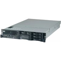

- Installation and User's Guide
- Tenth Edition (September 2012)
- © Copyright IBM Corporation 2012.
- Contents
- Chapter 1. The System x3650 M3 server . . . . . . . . . . . . . . . . . . 1
- Chapter 2. Installing optional devices. 2 5
- Appendix A. Getting help and technical assistance . . . . . . . . . . 1 6 1
- Appendix B. Notices 1 6 3
- Safety
- Statement 1:
- DANGER
- To avoid a shock hazard:
- To Connect: To Disconnect:
- Statement 2:
- CAUTION:
- Statement 3:
- Chapter 1. The System x3650 M3 server
- The IBM Documentation CD
- Hardware and software requirements
- Using the Documentation Browser
- Related documentation
- Notices and statements in this document
- Features and specifications
- Notes:
- What your server offers
- • UEFI-compliant server firmware
- - Integrated management module
- - Remote presence capability and blue-screen capture
- • IBM Dynamic System Analysis Preboot diagnostics programs
- • IBM Systems Director
- • Active Energy Manager
- • IBM X-Architecture technology
- - Active TM Memory
- – Large system-memory capacity
- • IBM ServerGuide Setup and Installation CD
- • Integrated network support
- • Large data-storage and hot-swap capability
- • Light path diagnostics
- - PCI adapter capabilities
- - Memory mirroring
- - Redundant connection
- - Redundant cooling and optional power capabilities
- - ServeRAID support
- - Systems-management capabilities
- • TCP/IP offload engine (TOE) support
- Reliability, availability, and serviceability features
- IBM Systems Director
- The UpdateXpress System Pack Installer
- Server controls, LEDs, and power
- Front view
- Operator information panel
- Light path diagnostics panel
- Rear view
- Power-supply LEDs
- Server power features
- Turning on the server
- Turning off the server
- Statement 5:
- Chapter 2. Installing optional devices
- Instructions for IBM Business Partners
- Server components
- System-board internal connectors
- System-board external connectors
- System-board switches and jumpers
- Important:
- System-board LEDs
- System pulse LEDs
- System-board optional device connectors
- SAS riser-card connectors and LEDs
- PCI riser-card adapter connectors
- PCI riser-card assembly LEDs
- Installation guidelines
- System reliability guidelines
- Working inside the server with the power on
- Handling static-sensitive devices
- Internal cable routing and connectors
- Removing the cover
- Removing a PCI riser-card assembly
- Installing a PCI riser-card assembly
- Removing the microprocessor 2 air baffle
- Installing the microprocessor 2 air baffle
- Removing the DIMM air baffle
- Installing the DIMM air baffle
- Installing the full-length-adapter bracket
- Storing the full-length-adapter bracket
- Installing a PCI adapter
- Attention:
- Removing a PCI adapter
- Installing an IBM Virtual Media Key
- Installing a hard disk drive
- Removing a hard disk drive
- Installing a simple-swap hard disk drive
- Removing a simple-swap hard disk drive
- Installing a SAS/SATA 4 Pac HDD upgrade option
- Installing a SAS/SATA 8 Pac HDD option
- Installing a SAS/SATA 8 Pac HDD for 2 RAID kit with 2 M5015 adapters option
- Installing an optional tape drive
- Converting a 16 bay system to a 8 bay + tape system
- Installing the tape drive option
- Installing a second microprocessor
- Thermal grease
- Installing a memory module
- DIMM installation sequence
- Memory mirroring
- Online-spare memory
- Installing a DIMM
- Installing a hot-swap ac power supply
- Removing a hot-swap fan
- Installing a hot-swap fan
- Removing the SAS riser-card and controller assembly
- Installing the SAS riser-card and controller assembly
- Removing a ServeRAID SAS controller from the SAS riser-card
- Installing a ServeRAID SAS controller on the SAS riser-card
- Installing an optional ServeRAID adapter advanced feature key
- Installing a ServeRAID SAS controller battery on the remote battery tray
- Moving the SAS controller retention bracket
- Installing a USB hypervisor memory key
- Removing a USB hypervisor memory key
- Installing the optional two-port Ethernet adapter
- Installing an optional DVD drive
- Completing the installation
- Replacing the server cover
- Connecting the external cables
- Updating the server configuration
- Chapter 3. Configuring the server
- - Setup utility
- - Boot Menu program
- - VMware embedded USB hypervisor
- - Ethernet controller configuration
- • LSI Configuration Utility program
- • IBM Advanced Settings Utility (ASU) program
- Using the Setup utility
- Starting the Setup utility
- Setup utility menu choices
- - System Information
- – System Summary
- - Product Data
- - System Settings
- - Processors
- - Memory
- – Devices and I/O Ports
- - Power
- - Operating Modes
- - Legacy Support
- - Force Legacy Video on Boot
- - Rehook INT
- - Legacy Thunk Support
- – Integrated Management Module
- - POST Watchdog Timer
- - POST Watchdog Timer Value
- - Reboot System on NMI
- - Commands on USB Interface Preference
- - Network Configuration
- - Reset IMM to Defaults
- - Reset IMM
- - Adapters and UEFI Drivers
- - Network
- - Storage
- • Video
- - Date and Time
- - Start Options
- - Boot Manager
- - System Event Logs
- - POST Event Viewer
- - System Event Log
- – Clear System Event Log
- - User Security
- - Set Power-on Password
- – Clear Power-on Password
- - Set Administrator Password
- – Clear Administrator Password
- - Save Settings
- - Restore Settings
- - Load Default Settings
- - Exit Setup
- Passwords
- Power-on password
- Administrator password
- Using the Boot Selection Menu program
- Starting the backup server firmware
- Using the ServerGuide Setup and Installation CD
- ServerGuide features
- Setup and configuration overview
- Typical operating-system installation
- Installing your operating system without using ServerGuide
- Using the integrated management module
- • Command-line interface (IPMI Shell)
- - Serial over LAN
- Using the USB memory key for VMware hypervisor
- Using the remote presence capability and blue-screen capture
- Enabling the remote presence feature
- Obtaining the IP address for the Web interface access
- Logging on to the Web interface
- Enabling the Broadcom Gigabit Ethernet Utility program
- Configuring the Gigabit Ethernet controller
- Using the LSI Configuration Utility program
- Starting the LSI Configuration Utility program
- Formatting a hard disk drive
- Creating a RAID array of hard disk drives
- IBM Advanced Settings Utility program
- Updating IBM Systems Director
- Appendix A. Getting help and technical assistance
- Before you call
- Using the documentation
- Getting help and information from the World Wide Web
- Software service and support
- Hardware service and support
- IBM Taiwan product service
- Appendix B. Notices
- Trademarks
- Important notes
- Particulate contamination
- Documentation format
- Telecommunication regulatory statement
- Electronic emission notices
- Federal Communications Commission (FCC) statement
- Industry Canada Class A emission compliance statement
- Australia and New Zealand Class A statement
- European Union EMC Directive conformance statement
- Germany Class A statement
- Japan VCCI Class A statement
- Japan Electronics and Information Technology Industries Association (JEITA) statement
- Korea Communications Commission (KCC) statement
- Russia Electromagnetic Interference (EMI) Class A statement
- People's Republic of China Class A electronic emission statement
- Taiwan Class A compliance statement
- A
- B
- C
- D
- DIMMs
- E
- F
- G
- H
- |
- J
- L
- M
- N
- 0
- P
- R
- S
- T
- U
- V
- W
Brand : IBM
Model : System x3650 M3
Category : Server