414 (1997) - Car Rover - Free user manual and instructions
Find the device manual for free 414 (1997) Rover in PDF.

User questions about 414 (1997) Rover
0 question about this device. Answer the ones you know or ask your own.
Ask a new question about this device
Download the instructions for your Car in PDF format for free! Find your manual 414 (1997) - Rover and take your electronic device back in hand. On this page are published all the documents necessary for the use of your device. 414 (1997) by Rover.
USER MANUAL 414 (1997) Rover
text_image
Haynes THE BOOKRover 214 & 414 Service and Repair Manual
Mark Coombs and Christopher Rogers
Models covered
(1689-288-9AA3)
Rover 214 and 414 models fitted with eight or sixteen-valve 1397 cc 'K-series' engine
Covers major mechanical features of Cabriolet
Does not cover Diesel engine models
© Haynes Publishing 1997
ABCDE FGHIJ KLMNO PQRST
A book in the Haynes Service and Repair Manual Series
All rights reserved. No part of this book may be reproduced or transmitted in any form or by any means, electronic or mechanical, including photocopying, recording or by any information storage or retrieval system, without permission in writing from the copyright holder.
ISBN 1 85960 458 7
British Library Cataloguing in Publication Data
A catalogue record for this book is available from the British Library.
Printed by J H Haynes & Co. Ltd, Sparkford, Nr Yeovil, Somerset BA22 7JJ
Haynes Publishing
Sparkford, Nr Yeovil, Somerset BA22 7JJ, England
Haynes North America, Inc
861 Lawrence Drive, Newbury Park, California 91320, USA
Editions Haynes S.A.
147/149, rue Saint Honoré, 75001 PARIS, France
Haynes Publishing Nordiska AB
REPAIRS AND OVERHAUL
Engine and Associated Systems
Engine in-car repair procedures Page 2A·1
Engine removal and general overhaul procedures Page 2B·1
Cooling, heating and ventilation systems Page 3·1
Fuel and exhaust systems - carburettor engines Page 4A·1
Fuel and exhaust systems - single-point fuel injected engines Page 4B·1
Fuel and exhaust systems - multi-point fuel injected engines Page 4C·1
Emission control systems Page 4D·1
Ignition system - carburettor engines Page 5A·1
Ignition system - fuel injected engines Page 5B·1
Starting and charging systems Page 5C·1
Transmission
Clutch Page 6·1
Gearbox Page 7·1
Driveshafts
Page 8·1
Brakes and Suspension
Braking system
Page 9·1
Suspension and steering
Page 10·1
Body Equipment
Bodywork and fittings
Page 11·1
Body electrical systems
Page 12·1
Wiring Diagrams
Page 12·20
REFERENCE
Dimensions and Weights
Page REF·1
Conversion Factors
Page REF·2
Buying Spare Parts and Vehicle Identification
Page REF·3
General Repair Procedures
Page REF·4
Jacking and Vehicle Support
Page REF·5
Radio/cassette Anti-theft System - precaution
Page REF·5
Tools and Working Facilities
Page REF·6
MOT Test Checks
Page REF·8
Fault Finding
Page REF·12
Glossary of Technical Terms
Page REF·19
Index
Page REF·24
Chapter 2 Part A
Engine in-car repair procedures
Contents
Camshaft oil seals - renewal 10
Camshafts and hydraulic tappets - removal, inspection and refitting 11
Compression test - description and interpretation 3
Crankshaft oil seals - renewal 17
Crankshaft pulley - removal and refitting 6
Cylinder head - removal and refitting 13
Cylinder head cover - removal and refitting 5
Engine oil and filter - renewal 2
Engine/gearbox mountings - inspection and renewal ..... 19
Flywheel - removal, inspection and refitting 18
General information and precautions 1
Oil pump - dismantling, inspection and reassembly ..... 16
Oil pump - removal and refitting 15
Sump - removal and refitting 14
Timing belt - removal, inspection, refitting and adjustment ..... 8
Timing belt covers - removal and refitting 7
Timing belt tensioner and sprockets - removal, inspection and refitting 9
Top Dead Centre (TDC) for number one piston - locating ..... 4
Valve clearances - general information 12
Degrees of difficulty
Easy, suitable for novice with little experience

Fairly easy, suitable for beginner with some experience

Fairly difficult, suitable for competent DIY mechanic

Difficult, suitable for experienced DIY mechanic

Very difficult, suitable for expert DIY or professional

Specifications
General
Type Four-cylinder in-line, four-stroke, liquid-cooled
Designation:
1.4 8-valve sohc K8
1.4 16-valve dohc ....K16
Bore 75.00 mm
Stroke 79.00 mm
Capacity 1396 cc
Firing order 1-3-4-2 (No 1 cylinder at timing belt end)
Direction of crankshaft rotation Clockwise (seen from right-hand side of vehicle)
Compression ratio:
K8 9.75:1
K16 9.50:1
Minimum compression pressure 10.3 bar
Maximum compression pressure difference between cylinders ..... 1.4 bar
Maximum power (EEC):
K8 76 ps (56 kW) @ 5700 rpm
K8 (with catalytic converter) 75 ps (55 kW) @ 5500 rpm
K16 95 ps (70 kW) @ 6250 rpm
K16 (with catalytic converter) 90 ps (66 kW) @ 6250 rpm
Maximum torque (EEC):
K8 117 Nm (86 lbf ft) @ 3500 rpm
K16 124 Nm (91 lbf ft) @ 4000 rpm
K16 (with catalytic converter) 120 Nm (89 lbf ft) @ 4000 rpm
Cylinder block/crankcase
Note: Service liners are Grade B
Material …… Aluminium alloy
Cylinder liner bore diameter - 60 mm from top of bore:
Standard - grade A (Red) 74.975 to 74.985 mm
Standard - grade B (Blue) 74.986 to 74.995 mm
Service limit 75.045 mm
Crankshaft
Number of main bearings 5
Main bearing journal diameter 47.979 to 48.000 mm
Main bearing journal size grades:
Grade A 47.993 to 48.000 mm
Grade B 47.986 to 47.993 mm
Grade C 47.979 to 47.986 mm
Crankpin journal diameter 42.986 to 43.007 mm
Crankpin journal size grades:
Grade A 43.000 to 43.007 mm
Grade B 42.993 to 43.000 mm
Grade C 42.986 to 42.993 mm
Main bearing and crankpin journal maximum ovality 0.010 mm
Main bearing and big-end bearing running clearance 0.021 to 0.049 mm
Crankshaft endfloat:
Standard 0.10 to 0.30 mm
Service limit 0.50 mm
Thrustwasher thickness 2.61 to 2.65 mm
Gudgeon pins
Diameter 18.0 mm
Fit in connecting rod . . . . . . . . . . . . . . . . . . . . . . . . . . . . . . . . . . . . . . . . . . . . . . . . . . . . . . . . . . . . . . . . . . . . . . . . . . . . . . . . . . Interference
Pistons and piston rings
Note: Service pistons are Grade B
Piston diameter: Grade A Grade B
K8 74.940 to 74.955 mm 74.956 to 74.970 mm
K16 74.945 to 74.960 mm 74.960 to 74.975 mm
Piston-to-bore clearance:
K8-standard 0.015 to 0.045 mm
K16-standard 0.010 to 0.040 mm
Service limit - all 0.080 mm
Piston ring end gaps (fitted 20 mm from top of bore):
Top compression ring:
K8 0.25 to 0.45 mm
K16 0.30 to 0.50 mm
Second compression ring - all models 0.30 to 0.50 mm
Oil control ring:
K8-standard 0.25 to 1.00 mm
K16:
standard 0.25 to 0.50 mm
service limit 0.60 mm
Piston ring-to-groove clearance:
Top compression ring:
K8 0.04 to 0.09 mm
K16 0.04 to 0.07 mm
Second compression ring:
K8 0.04 to 0.08 mm
K16 0.04 to 0.07 mm
Oil control ring - all models 0.02 to 0.06 mm
Cylinder head
Material …… Aluminium alloy
Height 118.95 to 119.05 mm
Reface limit 0.20 mm
Maximum acceptable gasket face distortion 0.05 mm
Valve seat angle 45°
Valve seat width 1.5 mm
Seat cutter correction angle:
Upper 30°
Lower 60°
Valve stem installed height:
K8:
new 38.95 to 40.81 mm
service limit 41.06 mm
K16:
new 38.93 to 39.84 mm
service limit 40.10 mm
Valves
Seat angle:
Inlet 45°
Exhaust 44°30'
Head diameter:
Inlet:
K8 34.0 mm
K16 28.0 mm
Exhaust:
K8 31.0 mm
K16 24.0 mm
Stem outside diameter:
Inlet:
K8 6.967 to 6.975 mm
K16 5.952 to 5.967 mm
Exhaust:
K8 6.952 to 6.967 mm
K16 5.947 to 5.962 mm
Guide inside diameter:
K8 7.000 to 7.025 mm
K16 6.000 to 6.025 mm
Stem-to-guide clearance:
Inlet:
standard 0.03 to 0.04 mm
service limit 0.07 mm
Exhaust:
standard 0.07 to 0.08 mm
service limit 0.11 mm
Valve timing:
K8:
Inlet opens 13° BTDC
Inlet closes 47° ABDC
Exhaust opens 53° BBDC
Exhaust closes 7° ATDC
K16:
Inlet opens 15° BTDC
Inlet closes 45° ABDC
Exhaust opens 55° BBDC
Exhaust closes 5° ATDC
Valve spring free length:
K8 46.2 mm
K16 50.0 mm
Valve guide fitted height 6.0 mm
Camshaft
Drive Toothed belt
Number of bearings 6
Bearing journal running clearance:
Standard 0.060 to 0.094 mm
Service limit 0.150 mm
Camshaft endfloat:
Standard 0.060 to 0.190 mm
Service limit 0.500 mm
Valve lift:
K8 9.0 mm
K16 8.2 mm
Hydraulic tappet outside diameter 32.959 to 32.975 mm
Lubrication system
System pressure 1.0 bar @ idle speed
Oil pump type Trochoidal, eccentric-rotor
Oil pump clearances:
Rotor endfloat 0.02 to 0.06 mm
Outer rotor-to-body clearance 0.28 to 0.36 mm
Rotor lobe clearance 0.05 to 0.13 mm
Pressure relief valve operating pressure 4.1 bar
Oil pressure warning lamp lights at .... Below 0.3 to 0.5 bar
Torque wrench settings Nm lbf ft
Spark plug (HT) lead clip screws - K8 97
Air intake duct support bracket-to-cylinder head screws 43
Spark plug cover screws - K16 2 1.5
Cylinder head cover bolts 97
Camshaft bearing cap/carrier-to-cylinder head bolts 97
Cylinder head bolts:
1st stage 20 15
2nd stage Tighten through 180°
Tighten through (a further) 180°
Timing belt cover fasteners:
Upper right-hand (outer) cover 43
Lower and upper left-hand (inner) covers 97
Timing belt tensioner backplate clamp bolt 25 19
Timing belt tensioner pulley Allen screw 45 33
Camshaft sprocket bolt 33 24
Crankshaft pulley bolt 160 118
Oil pump-to-cylinder block/crankcase bolt and screws 97
Alternator mounting bracket-to-cylinder block/crankcase bolts ..... 45 33
Dipstick tube-to-cylinder block/crankcase bolts 97
Flywheel bolts 85 63
Transmission-to-engine bolts 85 63
Flywheel cover plate screws 97
Flywheel rear cover plate bolt and nut 38 28
Big-end bearing cap bolts:
1st stage 20 15
2nd stage Tighten through 45°
Main bearing ladder-to-cylinder block/crankcase bolts 10 7
Oil rail-to-main bearing ladder nuts 97
Oil pump pick-up/strainer pipe bolts 97
Sump bolts 10
Engine oil drain plug 42 31
Engine/transmission right-hand mounting:
Bracket-to-cylinder block/crankcase bolts 45 33
Mounting-to-bracket nuts 100 74
Mounting-to-body through-bolt and nut 85 63
Engine/transmission left-hand mounting:
Mounting-to-body bolts 45 33
Mounting-to-transmission bracket bolts 60 44
Transmission bracket bolts 100 74
Engine/transmission rear mounting:
Mounting bracket-to-transmission bolt 85 63
Connecting link-to- transmission bracket bolt 60 44
Connecting link-to-body bolt 85 63
Anti-beaming bracket-to-support bracket bolt 45 33
7
1 General information and precautions
How to use this Chapter
This Part of the Chapter describes those repair procedures that can reasonably be carried out on the engine whilst it remains in the vehicle. If the engine has been removed from the vehicle and is being dismantled as described in Part B of this Chapter, any preliminary dismantling procedures can be ignored.
Note that whilst it may be possible physically to overhaul items such as the piston/connecting rod assemblies with the engine in the vehicle, such tasks are not usually carried out as separate operations and usually require the execution of several additional procedures (not to mention the cleaning of components and of oilways). For this reason, all such tasks are classed as major overhaul procedures and are described in Part B of this Chapter.
Engine information
The engine is of four-cylinder, in-line type, mounted transversely at the front of the vehicle with the clutch and transmission on its left-hand end. The engine is available in two forms - the K8 engine, which is the eight-valve single overhead camshaft engine fitted to the carburettor-equipped 214 S model, and the K16 engine, which is a sixteen-valve double overhead camshaft engine which is fitted to all fuel-injected models. Apart from the different cylinder head designs, both engines are of identical construction.
Apart from the pressed steel sump, the plastic timing belt covers and the aluminium alloy cylinder head cover, the engine consists of three major castings which are the cylinder head, the cylinder block/crankcase and the crankshaft main bearing ladder. There is also an oil rail underneath the main bearing ladder and the camshaft carrier/bearing caps.
All major castings are of aluminium alloy and are clamped together by ten long through-bolts which perform the dual role of cylinder head bolts and crankshaft main bearing fasteners. Since these bolts pass through the cylinder block/crankcase and the main bearing ladder, the oil rail is secured also to the main bearing ladder (by two nuts) and the main bearing ladder is secured also to the cylinder block/crankcase (by ten smaller bolts) so that the cylinder head can be removed without disturbing the rest of the engine. The passages provided for the bolts in the major castings are used as breather passages or as returns for the oil to the sump.
The crankshaft runs in five main bearings. Thrustwashers are fitted to the centre main bearing (upper half) to control crankshaft endfloat.
The connecting rods rotate on horizontally-split bearing shells at their big-ends. The pistons are attached to the connecting rods by gudgeon pins which are an interference fit in the connecting rod small-end eyes. The aluminium alloy pistons are fitted with three piston rings, comprising two compression rings and an oil control ring.
The cylinder bores are formed by replaceable wet liners which are located from their top ends. Two sealing rings are fitted at the base of each liner to prevent the escape of coolant into the sump.
The inlet and exhaust valves are each closed by coil springs and operate in guides pressed into the cylinder head. The valve seat inserts are pressed into the cylinder head and can be renewed separately if worn.
On the K8 engine, the camshaft is driven by a toothed timing belt and operates the eight valves via self-adjusting hydraulic tappets, thus eliminating the need for routine checking and adjustment of the valve clearances. The camshaft rotates in six bearings that are line-bored direct in the cylinder head and the (bolted-on) bearing caps. This means that the bearing caps are not available separately from the cylinder head and must not be interchanged with others from another engine. The distributor is driven from the left-hand end of the camshaft and the mechanical fuel pump is operated by an eccentric on the camshaft.
Apart from the fact that it has two camshafts, one inlet and one exhaust, each controlling eight valves and both retained by a single camshaft carrier, the same applies to the K16 engine. On the K16 engine, the distributor is driven from the left-hand end of the inlet camshaft. The fuel pump is electrically-operated.
On both engine types, the coolant pump is driven by the timing belt.
Lubrication is by means of an eccentric-rotor trochoidal pump mounted on the crankshaft right-hand end. It draws oil through a strainer located in the sump and then forces it through an externally-mounted full-flow cartridge-type filter into galleries in the oil rail and cylinder block/crankcase, from where it is distributed to the crankshaft (main bearings) and camshaft(s). The big-end bearings are supplied with oil via internal drillings in the crankshaft, while the camshaft bearings and the hydraulic tappets receive a pressurised supply. The camshaft lobes and valves are lubricated by splash, as are all other engine components.
Repair operations possible with the engine in the car
The following work can be carried out with the engine in the vehicle:
a) Compression pressure - testing.
b) Cylinder head cover - removal and refitting.
c) Crankshaft pulley - removal and refitting.
d) Timing belt covers - removal and refitting.
e) Timing belt - removal, refitting and adjustment.
f) Timing belt tensioner and sprockets - removal and refitting.
g) Camshaft oil seal(s) - renewal.
h) Camshaft(s) and hydraulic tappets - removal, inspection and refitting.
i) Cylinder head - removal and refitting.
j) Cylinder head and pistons - decarbonising.
k) Sump - removal and refitting.
1) Oil pump - removal, overhaul and refitting.
m) Crankshaft oil seals - renewal.
n) Engine/transmission mountings - inspection and renewal.
o) Flywheel - removal, inspection and refitting.
Precautions
Note that a side-effect of the above described engine design is that the crankshaft cannot be rotated once the cylinder head and block through-bolts have been slackened. During any servicing or overhaul work the crankshaft always must be rotated to the desired position before the bolts are disturbed.
2 Engine oil and filter - renewal
1 Details of checking the engine oil levels and renewing both the oil and filter are contained in "Weekly Checks" and Chapter 1.
3 Compression test - description and interpretation

1 When engine performance is down, or if misfiring occurs which cannot be attributed to the ignition or fuel systems, a compression test can provide diagnostic clues as to the engine's condition. If the test is performed regularly it can give warning of trouble before any other symptoms become apparent.
2 The engine must be fully warmed up to normal operating temperature, the battery must be fully charged and the spark plugs must be removed. The aid of an assistant will be required.
3 Disable the ignition system by disconnecting the ignition HT coil lead from the distributor cap and earthing it on the cylinder block. Use a jumper lead or similar wire to make a good connection.
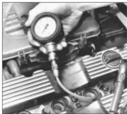
4 Fit a compression tester to the No 1 cylinder spark plug hole. The type of tester which screws into the plug thread is preferred (see illustration).
5 Have the assistant hold the throttle wide open and crank the engine on the starter motor. After one or two revolutions, the compression pressure should build up to a maximum figure and then stabilise. Record the highest reading obtained.
6 Repeat the test on the remaining cylinders, recording the pressure in each.
7 All cylinders should produce very similar pressures. Any difference greater than that specified indicates the existence of a fault. Note that the compression should build up quickly in a healthy engine. Low compression on the first stroke, followed by gradually increasing pressure on successive strokes, indicates worn piston rings. A low compression reading on the first stroke, which does not build up during successive strokes, indicates leaking valves or a blown head gasket (a cracked head could also be the cause). Deposits on the undersides of the valve heads can also cause low compression.
8 If the pressure in any cylinder is reduced to the specified minimum or less, carry out the following test to isolate the cause. Introduce a teaspoonful of clean oil into that cylinder through its spark plug hole and repeat the test.
9 If the addition of oil temporarily improves the compression pressure, this indicates that bore or piston wear is responsible for the pressure loss. No improvement suggests that leaking or burnt valves, or a blown head gasket, may be to blame.
10 A low reading from two adjacent cylinders is almost certainly due to the head gasket having blown between them and the presence of coolant in the engine oil will confirm this.
11 If one cylinder is about 20 percent lower than the others and the engine has a slightly rough idle, a worn camshaft lobe could be the cause.
12 If the compression reading is unusually high, the combustion chambers are probably coated with carbon deposits. If this is the case, the cylinder head should be removed and decarbonised.
13 On completion of the test, refit the spark plugs and reconnect the ignition system.
natural_image
Close-up of a hand holding a pressure gauge over an engine cylinder (no visible text or symbols)3.4 Measuring compression pressure
4 Top Dead Centre (TDC) for number one piston - locating

General
1 The crankshaft pulley, crankshaft and camshaft sprockets are provided by the factory with clear marks which align only at 90° BTDC. This positions the pistons half-way up the bores so that there is no risk of damage as the engine is reassembled. These marks do not indicate TDC. Use only the ignition timing marks, as described in this Section, to find TDC.
2 Top dead centre (TDC) is the highest point in its travel up-and-down the cylinder bore that each piston reaches as the crankshaft rotates. While each piston reaches TDC both at the top of the compression stroke and again at the top of the exhaust stroke, for the purpose of timing the engine, TDC refers to the piston position (usually No 1) at the top of its compression stroke.
3 While all engine reassembly procedures use the factory timing marks (90° BTDC), it is useful for several other servicing procedures to be able to position the engine at TDC.
4 No 1 piston and cylinder is at the right-hand (timing belt) end of the engine. Note that the crankshaft rotates clockwise when viewed from the right-hand side of the vehicle.
Locating TDC
5 Disconnect the battery negative lead and remove all the spark plugs.
6 Trace No 1 spark plug (HT) lead from the plug back to the distributor cap and use chalk or similar to mark the distributor body or engine casting nearest to the cap's No 1 terminal. Undo the distributor cap retaining screws and remove the cap.
7 Apply the handbrake and ensure that the transmission is in neutral, then jack up the front of the vehicle and support it on axle stands. Remove the right-hand roadwheel.
8 From underneath the front of the vehicle, slacken and remove the three bolts securing the bumper flange to the body. Remove the seven bolts securing the front undercover panel to the body and remove the panel to gain access to the crankshaft pulley and ignition timing marks.
9 Using a spanner, or socket and extension bar, applied to the crankshaft pulley bolt, rotate the crankshaft clockwise until the notch on the crankshaft pulley's inboard (left-hand) rim is aligned with the TDC mark on the timing belt lower cover (see Chapter 1 for details of ignition timing marks).
10 With the crankshaft in this position, Nos 1 and 4 cylinders are now at TDC, one of them on the compression stroke. If the distributor rotor arm is pointing at (the previously-marked) No 1 terminal, then No 1 cylinder is correctly positioned. If the rotor arm is pointing at No 4 terminal, rotate the crankshaft one full turn (360°) clockwise until the arm points at the

natural_image
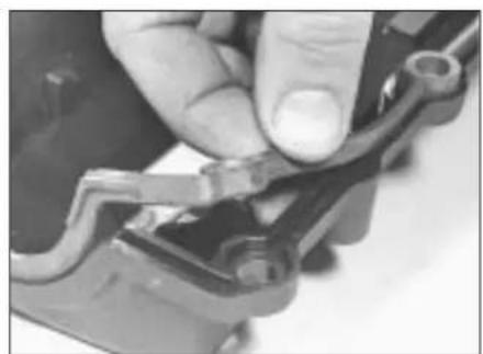
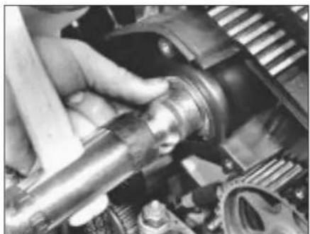
Close-up of hands adjusting a mechanical component with hoses and tubing (no visible text or symbols)5.3a Disconnecting breather hose from cylinder head cover - K8 engine
marked terminal. No 1 cylinder will then be at TDC on the compression stroke.
11 Once No 1 cylinder has been positioned at TDC on the compression stroke, TDC for any of the other cylinders can then be located by rotating the crankshaft clockwise 180^ at a time and following the firing order.
5 Cylinder head cover - removal and refitting

Removal
1 Disconnect the battery negative lead.
2 Remove the air cleaner assembly and metal intake duct.
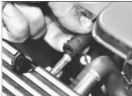
3 Using a suitable pair of pliers, release the retaining clip(s) and disconnect the breather hose(s) from the cylinder head cover (see illustrations).
K8 engines
4 Undo the bolts securing the HT lead mounting and air intake support brackets to the cylinder head cover, then remove the brackets and position the HT leads clear of the cover.
5 Remove the two uppermost retaining screws securing the timing belt upper right-hand/outer cover to the cylinder head cover, then slacken the remaining screws and bolts, as necessary, until the timing belt cover can be prised clear of the cylinder head cover without damaging it.
6 Working progressively and in the reverse of the tightening sequence (see illustration 5.14),
natural_image
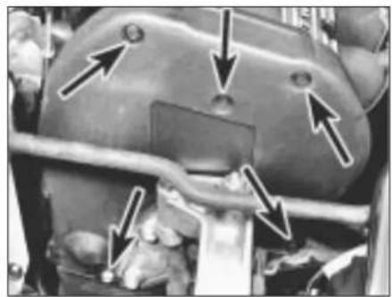
Close-up of a hand adjusting a mechanical component (no visible text or symbols)5.12a Ensure seal is correctly seated in cylinder head cover groove ...
natural_image
Close-up of hands using a tool to adjust or install electronic components (no visible text or symbols)5.3b Disconnecting breather hoses from cylinder head cover - K16 engine
slacken and remove the cylinder head cover retaining bolts.
7 Remove the cover, peel off the rubber seal and check it for cuts, other damage or distortion. Renew the seal if necessary.
K16 engines
8 Undo the two spark plug cover retaining screws and lift off the cover. Disconnect the HT leads from the plugs and withdraw them from the cylinder head, along with the clip plate and the grommet which is fitted to the left-hand end of the cylinder head cover.
9 Working progressively and in the reverse of the tightening sequence (see illustration 5.22), slacken and remove the cylinder head cover retaining bolts, noting the correct fitted position of the air intake duct support bracket.
10 Carefully lift off the cylinder head cover, taking care not to damage the gasket. Check that the gasket sealing path is undamaged and is attached to the gasket all around its periphery. If the sealing path is undamaged, then the gasket is re-usable and should remain in place on the cover until reassembly, unless its removal is necessary for other servicing work.
Refitting
K8 engines
11 On reassembly, carefully clean the cylinder head mating surfaces and the cover seal's groove and remove all traces of oil.
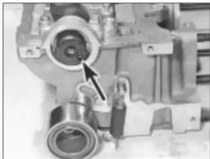
12 Seat the seal in its groove in the cover and refit the bolts, pushing each through the seal, then apply a smear of silicone-RTV sealant to each corner of the seal (see illustrations).

natural_image
Cross-sectional view of a mechanical component with arrows indicating internal features (no text or symbols)5.12b ... then refit bolts and apply sealant at locations arrowed - K8 engine
text_image
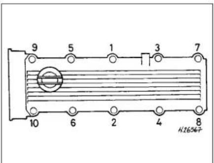
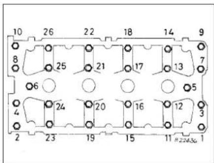
9 5 1 3 7 10 6 2 4 8 H165475.14 Cylinder head cover bolt tightening sequence - K8 engine
text_image
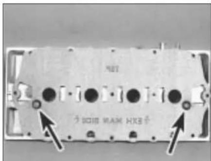
HBT 300M RAM HKB+5.20a Fit gasket to cylinder head cover dowels (arrowed) so that ...
natural_image
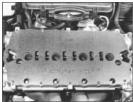
Close-up of an internal combustion engine block with mounting flanges and housing (no visible text or symbols)5.20b ... stamped markings would appear as shown if gasket were placed on camshaft carrier
13 Refit the cover to the cylinder head, ensuring that the seal remains seated in its groove. Fit all bolts, finger-tight.
14 Tighten the cylinder head cover bolts in the sequence shown to the specified torque wrench setting (see illustration).
15 Refit the timing belt upper right-hand/outer cover to the cylinder head cover and tighten all the disturbed screws and bolts to the specified torque setting.
16 Refit the HT lead mounting clips and air cleaner intake support brackets to the cylinder head, then tighten the retaining bolts to the specified torque. Ensure the HT leads are correctly routed.
17 Connect the breather hose to the cylinder head cover and secure it in position with the retaining clip.
18 Refit the air cleaner housing and reconnect the battery negative lead.
K16 engines
19 On reassembly, carefully clean the mating surfaces, removing all traces of oil. If the gasket has been removed, the oil separator elements can be cleaned by removing them from the cover and washing them in solvent. Use compressed air to blow dry the elements before refitting them to the cover.
20 If a new gasket is to be fitted, press it onto the cover locating dowels so that if it were laid on the camshaft carrier its stamped markings would be legible. The TOP mark should be nearest the inlet manifold and the EXH MAN SIDE mark should have its arrows pointing to the exhaust manifold (see illustrations).
21 Lower the cover onto the cylinder head, ensuring that the gasket is not damaged or displaced. Install the cover retaining bolts, not forgetting to refit the air intake duct support bracket to its original position, and tighten them finger-tight.
22 Working in the sequence shown, tighten the cylinder head cover retaining bolts to the specified torque setting (see illustration).
23 Reconnect the HT leads to the spark plugs, then locate the clip plate and grommet in the left-hand end of the cylinder head cover. Ensure the HT leads are correctly routed then refit the spark plug cover and tighten its retaining screws to the specified
torque. Tighten the air intake support bracket screws.
24 Connect both the breather hoses to the cylinder head cover and secure them in position with the retaining clips.
25 Refit the air cleaner housing and reconnect the battery negative lead.
6 Crankshaft pulley - removal and refitting

Removal
1 Apply the handbrake then jack up the front of the vehicle and support it on axle stands. Remove the right-hand roadwheel.
2 From underneath the front of the vehicle, slacken and remove the three bolts securing the bumper flange to the body. Remove the seven bolts securing the front undercover panel to the body and remove the panel.
3 If necessary, rotate the crankshaft until the relevant timing marks align.
4 Remove the power steering pump and/or alternator drivebelt(s) (as applicable).
5 To prevent crankshaft rotation while the pulley bolt is unscrewed, select top gear and have an assistant apply the brakes firmly. If the engine has been removed from the
text_image
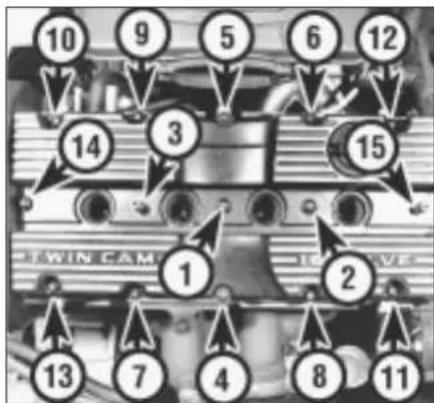
10 9 5 6 12 14 3 15 1 2 TWIN CAM 13 7 4 8 115.22 Cylinder head cover bolt tightening sequence - K16 engine
vehicle, lock the flywheel using the arrangement shown (see illustration 18.2).
6 Unscrew the pulley bolt, noting the special washer behind it, then remove the pulley from the crankshaft.
Refitting
7 Align the crankshaft pulley centre notch with the locating lug on the crankshaft timing belt sprocket then refit the washer, ensuring that its flat surface is facing the pulley. Fit the retaining bolt (see illustration).
8 Lock the crankshaft by the method used on removal and tighten the pulley retaining bolt to the specified torque setting.
9 Refit the power steering pump and/or alternator drivebelt(s) (as applicable) and adjust them as described in Chapter 1.
10 Refit the undercover panel and roadwheel then lower the vehicle to the ground.
7 Timing belt covers - removal and refitting

Removal
Upper right-hand (outer) cover
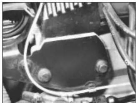
1 Slacken the bolt situated at the cover's bottom corner, immediately behind the engine/gearbox unit right-hand mounting bracket.

natural_image
Close-up of a mechanical component with a pointed tool inserted, showing concentric rings and a small arrow pointing to the tip (no visible text or symbols)6.7 Ensure notch in crankshaft pulley centre fits over crankshaft timing belt sprocket locating lug (arrowed)

text_image
1 2 H.265687.2a Timing belt upper right-hand (outer) cover fasteners - K8 engine
1 Slacken screw - cover should be slotted 2 Remove fasteners
2 Unscrew the remaining cover retaining bolts and withdraw the cover, noting the rubber seal fitted to the mounting bracket edge. Note that if the cover is not slotted at the bottom corner screw's location, the screw

natural_image
Close-up mechanical assembly showing gears and shafts with directional arrows indicating movement (no text or symbols)7.9a Timing belt upper left-hand (inner) cover fasteners (arrowed) - K8 engine

natural_image
Close-up mechanical assembly showing gears and shafts with directional arrows indicating motion (no text or symbols)7.9b Timing belt upper left-hand (inner) cover fasteners (arrowed) - K16 engine
natural_image
Close-up of a mechanical component with arrows pointing to features (no visible text or symbols)cover fasteners (arrowed) - K16 engine, raised for clarity
will have to be removed fully. If this is the case, the cover can be slotted to ease future removal and refitting (see illustrations).
Lower cover
3 Remove the crankshaft pulley.
4 Remove the cover retaining screws, including the one which also secures the upper cover's bottom front corner. Remove the cover whilst noting the rubber seal fitted to its mounting bracket edge (see illustration).
Upper left-hand (inner) cover
5 Remove the timing belt.
6 Remove the camshaft sprocket(s) and the timing belt tensioner.
7 Unscrew the bolt securing the cover to the coolant pump.
8 On K16 engines, unbolt the engine/gearbox unit right-hand mounting bracket from the cylinder block/crankcase.
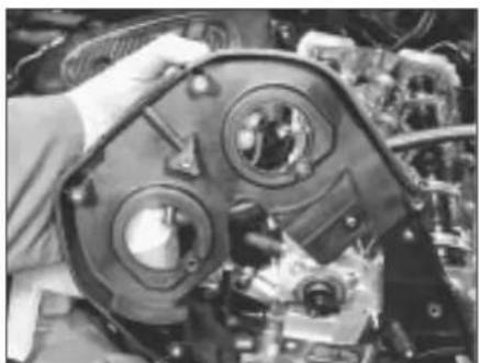
9 Remove the remaining cover retaining bolts and withdraw the cover (see illustrations).
Refitting
Upper right-hand (outer) cover
10 Refitting is the reverse of the removal procedure. Ensure that the seal fits correctly between the cover and the mounting bracket and that the cover edges mate correctly with those of the inner cover and (K8 engines only) cylinder head cover (see illustration).
11 Tighten the cover fasteners to the specified torque setting.
natural_image
Close-up of a mechanical assembly with gears and components, no visible text or symbols7.9c Removing timing belt upper left-hand (inner) cover - K16 engine
natural_image
Close-up of hands adjusting a mechanical component with no visible text or symbols7.4 Removing timing belt lower cover7.2b Timing
Lower cover
12 Refitting is the reverse of the removal procedure. Ensure that the seal fits correctly between the cover and the mounting bracket and tighten the cover fasteners to the specified torque setting.
Upper left-hand (inner) cover
13 Refitting is the reverse of the removal procedure. Tighten all disturbed fasteners to their specified torque wrench settings.
8 Timing belt - removal, inspection, refitting and adjustment


If the timing belt is to be reused, use white paint or similar to mark the direction of rotation on the belt.
Removal
1 Disconnect the battery negative lead.
2 To improve access to the timing belt, remove the expansion tank mounting bolts then free the coolant hose from any relevant retaining clips and position the tank clear of the engine. On models equipped with power-assisted steering, undo all the power steering hose retaining clip bolts then slide the fluid reservoir out of its retaining clip and position it
natural_image
Close-up of mechanical components including a motor and gears (no visible text or symbols)7.10 Ensure timing belt upper right-hand (outer) cover engages correctly with cylinder head cover - K8 engine
text_image
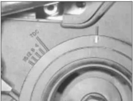
100 m2648.6 Crankshaft pulley mark aligned with timing belt lower cover mark at 90° BTDC
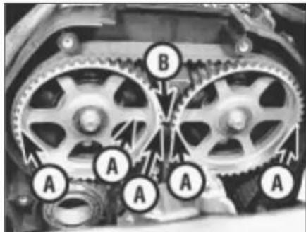
text_image
A A A A B8.7 Camshaft sprocket marks (A) aligned with timing belt upper left-hand (inner) cover mark (B) - K16 engine

natural_image
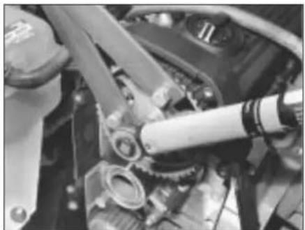
Close-up of hands using a tool to adjust mechanical components (no visible text or symbols)8.11 Removing engine/gearbox unit right-hand mounting bracket - K8 engine
clear of the timing belt covers. Take great care not to place any undue strain on hoses and mop up any spilt fluid immediately.
3 Remove the timing belt upper right-hand (outer) cover.
4 Firmly apply the handbrake then jack up the front of the vehicle and support it on axle stands. Remove the right-hand roadwheel
5 From underneath the front of the vehicle, slacken and remove the three bolts securing the bumper flange to the body. Remove the seven bolts securing the front undercover panel to the body and remove the panel to gain access to the crankshaft pulley bolt.
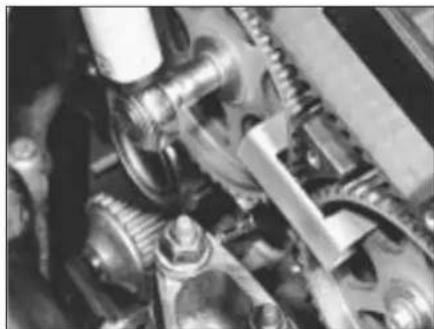
6 Using a suitable spanner or socket on the crankshaft pulley bolt, rotate the crankshaft in a clockwise direction until the long white-painted mark on the crankshaft pulley's outboard (right-hand) face is aligned with the single, separate mark on the timing belt lower cover so that the crankshaft is in the 90° BTDC position (see Chapter 1 for details of the pulley/cover marks) (see illustration).
7 Check that the camshaft sprocket mark(s) align as described in paragraph 15, showing that Nos 1 and 4 cylinders are at 90° BTDC so that there is no risk of the valves contacting the pistons during dismantling and reassembly. If the camshaft sprocket mark(s) are 180° out, rotate the crankshaft through one complete turn (360°) to align the marks as described (see illustration).
8 On K16 engines, use the tool described in Section 9 to lock up the camshaft sprockets
so that they cannot move under valve spring pressure when the timing belt is removed.
9 Remove the crankshaft sprocket and timing belt lower cover.
10 Position a trolley jack with a wooden spacer beneath the sump then gently jack it up to take the weight of the engine.
11 Slacken and remove the engine/gearbox unit right-hand mounting through-bolt and nut and the mounting-to-bracket nuts. Remove the mounting, along with the two rubber washers which are fitted on each side of the mounting. On K8 engines only, unscrew the retaining bolts securing the bracket to cylinder block/crankcase and remove it from the engine unit (see illustration).
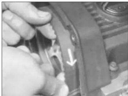
12 Slacken both the timing belt tensioner pulley Allen screw and the tensioner backplate clamp bolt through half a turn each, then push the pulley assembly downwards to remove all the tension from the timing belt. Hold the tensioner pulley in this position and re-tighten the backplate clamp bolt securely (see illustration).
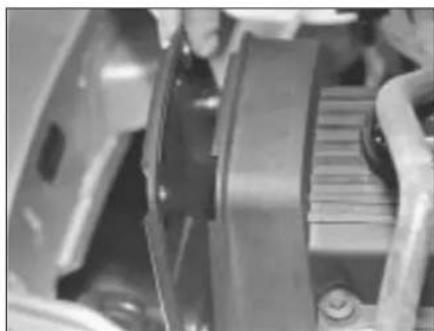
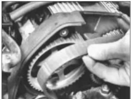
13 Slip the belt off the sprockets (see illustration). Do not rotate the crankshaft until the timing belt has been refitted.
Inspection
14 Check the timing belt carefully for any signs of uneven wear, splitting or oil contamination and renew it if there is the slightest doubt about its condition. If the engine is undergoing an overhaul and has
covered more than 48 000 miles (80 000 km) since the original belt was fitted, renew the belt as a matter of course, regardless of its apparent condition. If signs of oil contamination are found, trace the source of the oil leak and rectify it, then wash down the engine timing belt area and all related components to remove all traces of oil.
Refitting
15 On reassembly, thoroughly clean the timing belt sprockets and check that they are aligned as follows. It is most important that these marks are aligned exactly as this sets valve timing. Note that in this position, Nos 1 and 4 cylinders are at 90° BTDC so that there is no risk of the valves contacting the pistons during dismantling and reassembly.
a) Camshaft sprocket on K8 engine - The EX line and the mark stamped on the sprocket rim must be at the front (looking at the sprocket from the right-hand side of the vehicle) and aligned exactly with the cylinder head top surface (see illustration).
b) Camshaft sprockets on K16 engine - Both EXHAUST arrow marks must point to the rear (looking at the sprockets from the right-hand side of the vehicle) with the IN lines and the sprocket rim marks aligned exactly with the line on the timing belt upper left-hand/inner cover (representing the cylinder head top surface). See illustration 8.7.

text_image
A B8.12 Timing belt tensioner pulley bolt (A) and tensioner backplate clamp bolt (B)
natural_image
Close-up of a hand adjusting a mechanical component with a white arrow pointing to a detail (no visible text or symbols)8.13 Mark direction of rotation of timing belt before removal
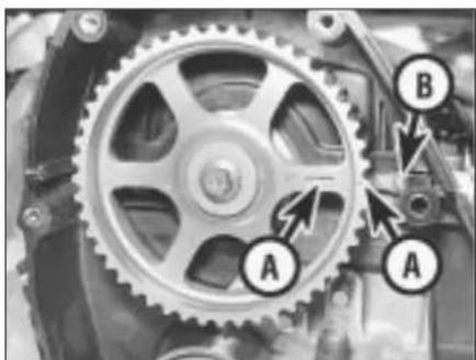
natural_image
Mechanical gear assembly diagram with labeled components A and B (no text or symbols beyond labels)8.15a Camshaft sprocket marks (A) aligned with cylinder head top surface (B) - K8 engine

text_image
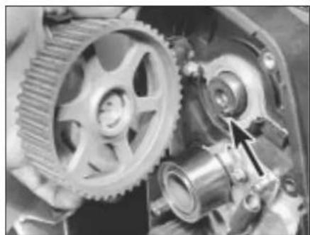
A A B8.15b Crankshaft sprocket dots (A) aligned on each side of oil pump raised rib (B)
c) Crankshaft sprocket - The two dots must be positioned on each side of the raised rib on the oil pump body (see illustration).
16 If a used belt is being refitted, ensure that the arrow mark made on removal points in the normal direction of rotation. Fit the timing belt over the crankshaft and camshaft sprockets, ensuring that the belt front run (and, on K16 engines, the top run) is taut, ie: all slack is on the tensioner pulley side of the belt, then fit the belt over the coolant pump sprocket and tensioner pulley. Do not twist the belt sharply during refitting and ensure that the belt teeth are correctly seated centrally in the sprockets and that the timing marks remain in alignment (see illustration).
17 Slacken the tensioner backplate clamp bolt and check that the tensioner pulley moves to tension the belt. If the tensioner assembly is not free to move under spring tension, rectify the fault or the timing belt will not be correctly tensioned.
18 On K16 engines, remove the camshaft sprocket locking tool.
19 On K8 engines, refit the engine/gearbox unit right-hand mounting bracket, tightening its bolts to the specified torque wrench setting.
20 On all engines, refit the timing belt lower cover and the crankshaft pulley.
21 Using a suitable spanner or socket, rotate the crankshaft two full turns clockwise to settle and tension the belt. Realign the crankshaft pulley (90° BTDC) mark and check that the sprocket timing mark(s) are still correctly aligned.
22 If all is well, first tighten the tensioner pulley backplate clamp bolt to the specified torque, then tighten the tensioner pulley Allen screw to the specified torque.
23 Reassemble the engine/gearbox unit right-hand mounting, ensuring that the rubber washers are correctly located, then tighten the mounting nuts and bolts to their specified torque settings. Remove the jack from underneath the engine unit.
24 Refit the front undercover panel and roadwheel, then lower the vehicle to the ground.
25 Refit the timing belt upper right-hand (outer) cover.
natural_image
Close-up of a hand adjusting a mechanical gear mechanism (no visible text or symbols)8.16 Refitting timing belt - K16 engine
26 Where necessary, refit the power steering fluid reservoir to the mounting bracket and secure the hydraulic hose clamps in position with the retaining bolts.
27 Refit the coolant expansion tank and tighten the mounting bolts securely. Secure the coolant hose in position with any necessary retaining clips and reconnect the battery negative lead.
Adjustment
28 As the timing belt is a 'fit-and-forget' type, the manufacturer states that tensioning need only be carried out when a belt is (re)fitted. No re-tensioning is recommended once a belt has been fitted and therefore this operation is not included in the manufacturer's maintenance schedule.
29 If the timing belt is thought to be incorrectly tensioned, then adjust the tension as described in paragraphs 1 to 7, 17, 21, 22 and 24 to 27 above.
30 If the timing belt has been disturbed, adjust its tension following the same procedure, omitting as appropriate the irrelevant preliminary dismantling/reassembly steps.
9 Timing belt tensioner and sprockets - removal, inspection and refitting


If both camshaft sprockets on K16 engines are to be removed, it is good practice to mark them (inlet or
exhaust) so that they can be returned to their original locations on reassembly.
Note: This Section describes as individual operations the removal and refitting of the components concerned. If more than one
text_image
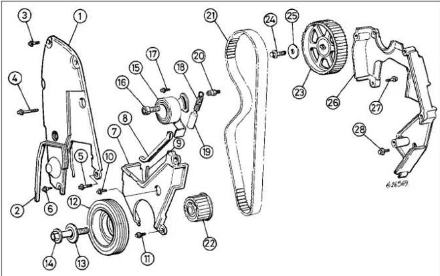
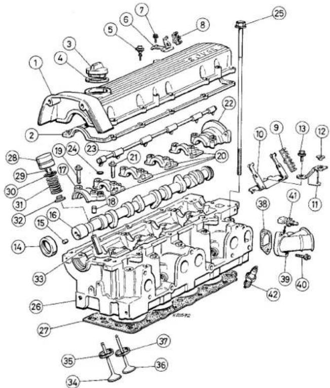
Technical diagram of a mechanical assembly with numbered parts for identification9.2a Timing belt, sprockets and covers - K8 engine
1 Timing belt upper right-hand (outer) cover
2 Seal
3 Bolt
4 Bolt
5 Bolt
6 Shouldered bolt
7 Timing belt lower cover
8 Seal
9 Seal
10 Bolt
11 Bolt
12 Crankshaft pulley
13 Washer
14 Crankshaft pulley bolt
15 Timing belt tensioner pulley assembly
16 Tensioner pulley Allen screw
17 Tensioner backplate clamp bolt
18 Tensioner pulley spring
19 Sleeve
20 Pillar bolt
21 Timing belt
22 Crankshaft sprocket
23 Camshaft sprocket
24 Camshaft sprocket bolt
25 Washer
26 Timing belt upper left-hand (inner) cover
27 Bolt - cover to water pump
28 Bolt

text_image
Exploded view diagram of a mechanical assembly with numbered parts for identification9.2b Timing belt, sprockets and covers - K16 engine
1 Timing belt upper right-hand (outer) cover
2 Bolt
3 Seal
4 Bolt
5 Timing belt lower cover
6 Seal
7 Bolt
8 Bolt
9 Crankshaft pulley
10 Washer 11 Crankshaft pulley bolt
12 Timing belt
13 Camshaft sprockets
14 Bolt
15 Washer
16 Timing belt tensioner pulley assembly
17 Tensioner pulley Allen screw
18 Tensioner pulley spring 19 Sleeve
20 Pillar bolt
21 Tensioner backplate clamp bolt
22 Crankshaft sprocket
23 Timing belt upper left-hand (inner) cover
24 Bolt
component needs to be removed at the same time, start by removing the timing belt, then remove each component as described below whilst ignoring the preliminary dismantling steps.
Removal
1 Disconnect the battery negative lead. 2 To improve access to the timing belt components (see illustrations), remove the expansion tank mounting bolts then free the coolant hose from any relevant retaining clips and position the tank clear of the engine. On models equipped with power-assisted steering, undo all the power steering hose retaining clip bolts then slide the fluid reservoir out of its retaining clip and position it clear of the timing belt covers. Take great care not to place any undue strain on hoses and mop up any spilt fluid immediately.
3 Remove the timing belt upper right-hand (outer) cover.
4 Apply the handbrake then jack up the front of the vehicle and support it on axle stands. Remove the right-hand roadwheel.
5 From underneath the front of the vehicle, slacken and remove the three bolts securing the bumper flange to the body. Remove the seven bolts securing the front undercover panel to the body and remove the panel.
6 Using a suitable spanner or socket on the crankshaft pulley bolt, rotate the crankshaft in
a clockwise direction until the long white-painted mark on the crankshaft pulley's outboard (right-hand) face is aligned with the single, separate mark on the timing belt lower cover so that the crankshaft is in the 90° BTDC position (see Chapter 1 for details of the pulley/cover marks).
7 Check that the camshaft sprocket mark(s) align as described in Section 8, paragraph 15 then proceed as described under the relevant sub-heading.
Camshaft sprocket(s)
8 Slacken through half a turn each, the timing belt tensioner pulley Allen screw and the tensioner backplate clamp bolt. Push the pulley assembly down to release all tension from the timing belt, then re-tighten the backplate clamp bolt securely.
9 Remove the belt from the camshaft sprocket(s), taking care not to twist it too sharply. Use fingers only to handle the belt. Do not rotate the crankshaft until the timing belt is refitted.
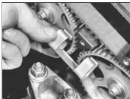
10 On K8 engines, slacken the camshaft sprocket retaining bolt and remove it, along with its washer. To prevent the camshaft from rotating, use Rover service tool 18G 1521 to retain the sprocket. If the tool is not available, then an acceptable substitute can be fabricated from two lengths of steel strip (one long, the other short) and three nuts and bolts. One nut and bolt should form the pivot of a forked tool with the remaining two nuts and bolts at the tips of the forks to engage with the sprocket spokes, as shown in illustration 9.23a.
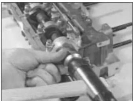
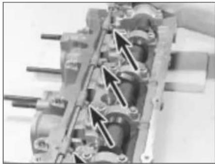
11 On K16 engines, unscrew the appropriate camshaft sprocket retaining bolt and remove it, along with its washer. To prevent a camshaft from rotating, lock together both sprockets using Rover service tool 18G 1570. This tool is a metal sprag shaped on both sides to fit the sprocket teeth and is inserted between the sprockets. If the tool is not available, then an acceptable substitute can be cut from a length of square-section steel tube or similar to fit as closely as possible around the sprocket spokes (see illustrations).
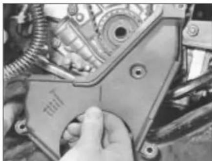
12 On all engines, remove the sprocket(s) from the camshaft end(s), noting the locating roll pin(s) (see illustration). If a roll pin is a

natural_image
White plastic mechanical component with three protrusions (no text or symbols visible)9.11a Camshaft locking tool cut from steel section...
natural_image
Close-up of hands assembling mechanical gears and linkages (no visible text or symbols)9.11b ... to fit sprocket spokes as closely as possible - K16 engine
natural_image
Close-up of mechanical gears and shafts in a vehicle (no visible text or symbols)9.12 Removing camshaft sprocket (roll pin arrowed) - K8 engine
loose fit in the camshaft end, remove it and store it with the sprocket for safe-keeping.
Crankshaft sprocket
13 On K16 engines, use the tool described in paragraph 11 to lock together the camshaft sprockets so that they cannot move under valve spring pressure when the timing belt is removed.
14 Remove the crankshaft pulley and timing belt lower cover.
15 Slacken through half a turn each the timing belt tensioner pulley Allen screw and the tensioner backplate clamp bolt, push the pulley assembly down to release all the tension from the timing belt, then re-tighten the backplate clamp bolt securely.
16 Work the belt clear of the crankshaft sprocket, taking care not to twist it too sharply. Use fingers only to handle the belt. Do not rotate the crankshaft until the timing belt is refitted.
17 Remove the sprocket from the crankshaft.
Tensioner assembly
18 On K16 engines, use the tool described in paragraph 11 to lock together the camshaft sprockets so that they cannot move under valve spring pressure when the timing belt is removed.
19 Using a suitable pair of pliers, unhook the tensioner spring from the pillar bolt. Unscrew the tensioner pulley Allen screw and the tensioner backplate clamp bolt then withdraw the tensioner assembly from the engine unit. Do not rotate the crankshaft until the timing belt is re-tensioned.
Inspection
20 Clean thoroughly the camshaft/crankshaft sprockets and renew any that show signs of wear, damage or cracks.
21 Clean the tensioner assembly but do not use any strong solvent which may enter the pulley bearing. Check that the pulley rotates freely on the backplate, with no sign of stiffness or of free play. Renew the assembly if there is any doubt about its condition or if
there are any obvious signs of wear or damage. The same applies to the tensioner spring, which should be checked with great care as its condition is critical for the correct tensioning of the timing belt.
Refitting
Camshaft sprocket(s)
22 If removed, refit the roll pin to the camshaft end, ensuring that its split is facing the centre of the camshaft, then refit the sprocket so that the timing marks are facing outwards (to the right). On K16 engines, ensure that the appropriate sprocket keyway engages with the camshaft locating pin (ie: if refitting the inlet camshaft sprocket, engage its IN keyway with the roll pin and so on) then refit the sprocket retaining bolt and washer (see illustration). Where necessary, repeat the procedure for the second sprocket.
23 Prevent the sprocket(s) from rotating by using the method employed on removal, then tighten the sprocket retaining bolt(s) to the specified torque setting. Check that the sprocket timing marks align as described in Section 8, paragraph 15 (see illustrations).
24 Fit the timing belt over the camshaft sprockets, ensuring that the belt front run (and, on K16 engines, the top run) is taut, that is, all slack is on the tensioner pulley side of the belt. Do not twist the belt sharply while refitting it and ensure that the belt teeth are correctly seated centrally in the sprockets and that the timing marks remain in alignment.
25 Slacken the tensioner backplate clamp bolt and check that the tensioner pulley moves to tension the belt. If the tensioner assembly is not free to move under spring tension, rectify the fault or the timing belt will not be correctly tensioned.
26 On K16 engines, remove the camshaft sprocket locking tool.
27 Using a suitable spanner or socket, rotate the crankshaft two full turns clockwise to settle and tension the belt. Realign the crankshaft pulley (90° BTDC) mark and check that the sprocket timing mark(s) are still correctly aligned.
28 If all is well, first tighten the tensioner pulley backplate clamp bolt to the specified torque, then tighten the tensioner pulley Allen screw to the specified torque.
29 Refit the front undercover panel and roadwheel, then lower the vehicle to the ground.
30 Refit the timing belt upper right-hand (outer) cover.
31 Where necessary, refit the power steering fluid reservoir to the mounting bracket and secure the hydraulic hose clamps in position with the retaining bolts.
32 Refit the coolant expansion tank and tighten the mounting bolts securely. Secure the coolant hose in position with any necessary retaining clips and reconnect the battery negative lead.
Crankshaft sprocket
33 Refit the sprocket to the crankshaft so that it locates correctly on the crankshaft's flattened section, noting that the sprocket flange must be innermost so that the two timing marks are on the outside (right-hand side) of the sprocket. Check that the sprocket timing marks align as described in Section 8, paragraph 15.
34 Fit the timing belt over the crankshaft sprocket, ensuring that the belt front run (and, on K16 engines, the top run) is taut, that is, all slack is on the tensioner pulley side of the belt. Do not twist the belt sharply while refitting it and ensure that the belt teeth are correctly seated centrally in the sprockets and that the timing marks remain in alignment.
35 Slacken the tensioner backplate clamp bolt and check that the tensioner pulley moves to tension the belt. If the tensioner assembly is not free to move under spring tension, rectify the fault or the timing belt will not be correctly tensioned.
36 On K16 engines, remove the camshaft sprocket locking tool.
37 Refit the lower timing belt cover and the crankshaft pulley.
38 Carry out the operations described in paragraphs 27 to 32.

natural_image
Close-up of a mechanical component with 'EXHAUST' label and internal cutout (no readable text beyond labels)9.22 Camshaft sprockets have two keyways. Engage EX keyway with exhaust camshaft roll pin and IN keyway with inlet camshaft roll pin - K16 engine
natural_image
Close-up of mechanical components including gears and linkages (no visible text or symbols)9.23a Using fabricated tool to hold camshaft pulley in position - K8 engine
natural_image
Close-up of mechanical gears and linkages in a gear assembly (no visible text or symbols)9.23b Locking camshafts in position with fabricated tool - K16 engine

natural_image
Close-up of mechanical gear and housing components (no visible text or symbols)9.39 Ensure timing belt tensioner spring is correctly hooked onto pillar bolt
natural_image
Close-up of a hand using a mechanical tool to adjust or install a component (no visible text or symbols)10.4 Fitting a new camshaft right-hand oil seal - K16 engine
natural_image
Close-up of a mechanical component with bolts and wiring (no visible text or symbols)10.8 Remove air intake duct support bracket to reach exhaust camshaft left-hand oil seal - K16 engine
Tensioner pulley
39 Refit the tensioner pulley assembly and tighten the pulley Allen screw and the backplate clamp bolt lightly. Hook the tensioner spring over the pillar bolt and check that the tensioner is free to move under spring tension and that the pulley bears correctly against the timing belt (see illustration).
40 On K16 engines, remove the camshaft sprocket locking tool.
41 Carry out the operations described above in paragraphs 27 to 32.
10 Camshaft oil seals - renewal

Note: If a right-hand oil seal is to be renewed with the timing belt still in place, then check that the belt is free from oil contamination. Renew the belt if signs of oil contamination are found. Cover the belt to protect it from contamination while work is in progress and ensure that all traces of oil are removed from the area before the belt is refitted.
Right-hand seal(s)
1 Remove the camshaft sprocket(s).
2 Punch or drill two small holes opposite each other in the oil seal. Screw a self-tapping screw into each and pull on the screws with pliers to extract the seal.
3 Clean the seal housing and polish off any burrs or raised edges which may have caused the seal to fail in the first place.
4 Lubricate the lips of the new seal with clean engine oil and drive it into position until it seats on its locating shoulder. Use a suitable tubular drift, such as a socket, which bears only on the hard outer edge of the seal (see illustration). Take care not to damage the seal lips during fitting and note that the seal lips should face inwards.
5 Refit the camshaft sprocket(s).
Left-hand seals - K16 engines
6 Disconnect the battery negative lead.
7 To reach the inlet camshaft seal, remove the distributor.
8 To reach the exhaust camshaft seal.
unfasten the rubber strap securing the air intake duct to its support bracket, disconnect the vacuum pipe from the air temperature control valve and unclip the pipe from the support bracket. Undo the bracket's retaining bolts and remove the bracket from the cylinder head (see illustration).
9 Remove the old seal and install the new one as described above in paragraphs 2 to 4.
10 On the inlet camshaft, refit the distributor.
11 On the exhaust camshaft, refit the air intake duct support bracket, tightening its screws to the specified torque wrench setting. Reconnect and secure the air temperature control valve vacuum pipe and refit the rubber strap to secure the air intake duct.
12 Connect the battery negative lead.
11 Camshafts and hydraulic tappets - removal, inspection and refitting

HAYNES HiNT
If faulty tappets are diagnosed and the engine's service history is unknown, it is always worth trying the
effect of renewing the engine oil and filter (using only good quality engine oil of the recommended viscosity and specification) before going to the expense of renewing any of the tappets.
Note: Prior to removing the camshaft(s), obtain Rover sealant kit LVV 10002 which also contains a plastic scraper. Read the instructions supplied with the kit and take care not to allow the sealant to contact the fingers, as it will bond the skin. If difficulty is experienced with the removal of hardened sealant from mating surfaces, it will be necessary to use a foam action gasket remover.
Removal
K8 engines
1 Remove the cylinder head cover (see illustration 11.0a overleaf).
2 Remove the distributor.
3 Remove the camshaft sprocket.
4 Carefully prise the oil feed tube away from the camshaft bearing caps and remove it from the head assembly. Remove the O-rings from the oil rail and discard them. The O-rings must be renewed whenever they are disturbed.
5 The camshaft right and left-hand end bearing caps are noticeably different and cannot be confused. The intermediate bearing caps (which are all similar) are marked by the manufacturer with a number (1, 2, 3, or 4) stamped in the boss next to the oil feed hole. Before unbolting any of the caps, make written notes to ensure that each can be easily identified and refitted in its original location.
6 Working in the reverse of the tightening sequence (see illustration 11.29), slacken the camshaft bearing cap bolts progressively, by one turn at a time. Work only as described to release the pressure of the valve springs on the bearing caps gradually and evenly.
7 Withdraw the bearing caps, noting the presence of the locating dowels on the end caps, then remove the camshaft and withdraw the oil seal.
8 Obtain eight small, clean plastic containers, number them 1 to 8, and then fill them with clean engine oil. Using a rubber sucker, withdraw each hydraulic tappet in turn (see illustration), and place it in its respective container, to prevent oil loss. Do not interchange the hydraulic tappets or the rate of wear will be much increased and do not allow them to lose oil or they will take a long

natural_image
Close-up of an engine component with visible shaft, housing, and mounting holes (no text or symbols)11.8 Use a valve-grinding sucker to extract hydraulic tappets
1 Cylinder head cover
2 Seal
3 Engine oil filler cap
4 Seal
5 Bolt
6 HT lead retaining clip bracket
7 Screw
8 HT lead retaining clip
9 HT lead retaining clip
10 HT lead retaining clip bracket
11 Air intake duct support bracket
12 Fastener insert
13 Bolt
14 Oil seal
15 Roll pin
16 Camshaft
17 Camshaft right-hand bearing cap*
18 Dowel
19 Bolt
20 Camshaft intermediate bearing cap*
21 Bolt
22 Camshaft left-hand bearing cap*
23 Oil feed tube
24 O-ring
25 Cylinder head bolt
26 Cylinder head
27 Cylinder head gasket
28 Hydraulic tappet
29 Split collets
30 Spring retainer
31 Valve spring
32 Valve stem seal/ spring lower seat
33 Valve guide
34 Inlet valve
35 Valve seat insert
36 Exhaust valve
37 Valve seat insert
38 Gasket
39 Coolant outlet elbow
40 Bolt
41 Coolant temperature gauge sender unit
42 Spark plug
* Note: Camshaft bearing caps shown for reference only - not available separately from cylinder head
text_image
Technical diagram of an engine cylinder with numbered components for identification11.0a Top end components - K8 engine
1 Spark plug cover
2 Screw
3 Retaining washer
4 Engine oil filler cap
5 Seal
6 Spark plug
7 Pillar bolt
8 HT lead grommet
9 HT lead clip plate
10 Bolt
11 Cylinder head cover
12 Gasket
13 Camshaft carrier*
14 Bolt
15 Cylinder head bolt
16 Inlet camshaft
17 Exhaust camshaft
18 Roll pin
19 Rotor arm drive spindle
20 Oil seal
21 Hydraulic tappet
22 Split collets
23 Spring retainer
24 Valve spring
25 Valve stem seal/spring lower seat
26 Cylinder head
27 Dowel
28 Cylinder head gasket
29 Valve guide
30 Inlet valves
31 Valve seat insert
32 Exhaust valves
33 Valve seat insert
34 Air intake duct support bracket
35 Bolt
36 Gasket
37 Coolant outlet elbow
38 Bolt
39 Coolant temperature gauge sender unit
* Note: Camshaft carrier shown for reference only - not available separately from cylinder head

text_image
Exploded view diagram of an engine cylinder assembly with numbered components11.0b Top end components - K16 engine

natural_image
Close-up of mechanical components with no visible text or symbols11.9 Secure partly-removed timing belt upper left-hand (inner) cover clear of cylinder head - K16 engine
time to refill with oil on restarting the engine, resulting in incorrect valve clearances.
K16 engines
9 Remove both camshaft sprockets, then unscrew the inner cover's upper retaining bolts so that the cover can be pulled away from the cylinder head just far enough for adequate working clearance. Take care not to distort or damage the cover or the timing belt (see illustration).
10 Remove the cylinder head cover (see illustration 11.0b).
11 Remove the distributor.
12 Unclip the air temperature control valve vacuum pipe from the air intake duct support bracket, then unbolt the bracket from the cylinder head.
13 Working in the reverse of the tightening sequence (see illustration 11.36), evenly and progressively slacken the camshaft carrier bolts by one turn at a time. Once all valve spring pressure has been relieved, remove the bolts.
14 Withdraw the camshaft carrier, noting the presence of the locating dowels, then remove the camshafts and slide off the oil seals. The inlet camshaft can be identified by the distributor rotor arm drive spindle (or its location), therefore there is no need to mark the camshafts.
15 Obtain sixteen small, clean plastic containers, number them 1 to 16, and then fill them with clean engine oil. Using a rubber

natural_image
Close-up of hands using a tool to adjust mechanical components in a mechanical assembly (no visible text or symbols)11.26 Lubricate hydraulic tappets thoroughly and refit correct way up - K8 engine
sucker, withdraw each hydraulic tappet in turn (see illustration 11.8), and place it in its respective container, to prevent oil loss. Do not interchange the hydraulic tappets or the rate of wear will be much increased and do not allow them to lose oil or they will take a long time to refill with oil on restarting the engine, resulting in incorrect valve clearances.
Inspection
16 Check each hydraulic tappet for signs of obvious wear (scoring, pitting, etc) and for ovality. Renew if necessary.
17 If the engine's valve clearances have sounded noisy, particularly if the noise persists after initial start-up from cold, then there is reason to suspect a faulty hydraulic tappet. Only a good mechanic experienced in these engines can tell whether the noise level is typical, or if renewal is warranted of one or more of the tappets.
18 If any tappet's operation is faulty, then it must be renewed.
19 Carefully remove all traces of old sealant from the mating surfaces of the bearing caps or camshaft carrier and cylinder head by using a plastic scraper. Examine the camshaft bearing journals and the cylinder head bearing surfaces for signs of obvious wear or pitting. If any such signs are evident, renew the component concerned.
20 To check the bearing journal running clearance, remove the hydraulic tappets, carefully clean the bearing surfaces and refit the camshaft(s) and carrier/bearing caps with a strand of Plastigauge across each journal. Tighten the carrier/bearing cap bolts to the specified torque wrench setting whilst taking great care not to rotate the camshaft(s), then remove the carrier/bearing caps and use the scale provided with the Plastigauge kit to measure the width of each compressed strand.
21 If the running clearance of any bearing is found to be worn to the specified service limit or beyond, fit a new camshaft and repeat the check. If the clearance is still excessive, then the cylinder head must be renewed.
22 To check camshaft endfloat, remove the hydraulic tappets, carefully clean the bearing surfaces and refit the camshaft(s) and carrier/bearing caps. Tighten to the specified
natural_image
Close-up of mechanical components with a black arrow pointing to a circular component (no visible text or symbols)11.27 Camshaft roll pin location at TDC position (for refitting camshaft bearing caps) - K8 engine
torque wrench setting the carrier/bearing cap bolts, then measure the endfloat using a Dial Test Indicator (DTI) or dial gauge mounted on the cylinder head so that its tip bears on the camshaft right-hand end.
23 Tap the camshaft fully towards the gauge, zero the gauge, then tap the camshaft fully away from the gauge and note the gauge reading. If the endfloat measured is found to be worn to the specified service limit or beyond, fit a new camshaft and repeat the check. If the clearance is still excessive, then the cylinder head must be renewed.
24 The camshaft itself should show no signs of marks, pitting or scoring on the lobe surfaces. If such marks are evident, renew the camshaft.
25 If a camshaft is renewed, extract the roll pin from the old one and fit the pin to the new camshaft with its split towards the camshaft's centre.
Refitting
K8 engines
26 Liberally oil the cylinder head hydraulic tappet bores and the tappets (see illustration). Note that if new tappets are being fitted, they must be charged with clean engine oil before installation. Carefully refit the tappets to the cylinder head, ensuring that each tappet is refitted to its original bore and is the correct way up. Some care will be required to enter the tappets squarely into their bores.
27 Liberally oil the camshaft bearings and lobes then refit the camshaft. Position the shaft so that its No 1 cylinder lobes are pointing away from their valves and the roll pin in the camshaft's right-hand end is in the 4 o'clock position when viewed from the right-hand end of the engine (see illustration).
28 Ensure that the locating dowels are pressed firmly into their recesses. Check that the mating surfaces are completely clean, unmarked and free from oil, then apply a thin bead of special Rover sealant to the mating surfaces of the front and rear bearing caps as shown (see illustration 11.29). Carefully follow the instructions supplied with the sealant kit. Refit the bearing caps, using the notes made on removal, to ensure that each is installed correctly and in its original location (see illustration).

natural_image
Close-up mechanical assembly showing a shaft and housing with directional arrows indicating components (no visible text or symbols)11.28 Apply sealant (arrowed) and fit camshaft bearing caps - K8 engine

text_image
12 8 4 2 6 10 11 7 3 1 5 9 H.265N11.29 Camshaft bearing cap bolt tightening sequence - K8 engine
Note: Apply thin bead of sealant to end bearing cap mating surfaces along paths shown by heavy black lines
29 Working in the sequence shown (see illustration), progressively tighten the camshaft bearing cap bolts by one turn at a time until the caps touch the cylinder head evenly. Now go round again, working in the same sequence, and tighten all the bolts to the specified torque setting. Work only as described to impose the pressure of the valve springs gradually and evenly on the bearing caps. Wipe off all surplus sealant so
natural_image
Close-up of mechanical components including gears and shafts in a machining or assembly (no visible text or symbols)11.31 Fitting a new camshaft right-hand oil seal - K8 engine

natural_image
Close-up of a metalworking machine tool with a screwdriver inserted into a machining process (no visible text or symbols)11.30a Fill oil holes with clean engine oil - K8 engine
that none is left to find its way into any oilways.
30 Squirt clean engine oil into each camshaft bearing cap oil hole, then fit new O-rings to each of the oil feed tube stubs (see illustration). Refit the oil feed tube to the cylinder head and press it firmly into position in the camshaft bearing caps.
31 Fit a new camshaft oil seal (see illustration), then refit the cylinder head cover and camshaft sprocket.
32 Refit the distributor.
K16 engines
33 Liberally oil the cylinder head hydraulic tappet bores and the tappets. Note that if new tappets are being fitted, they must be charged with clean engine oil before installation. Carefully refit the tappets to the cylinder head, ensuring that each tappet is refitted to its original bore and is the correct way up. Some care will be required to enter the tappets squarely into their bores.
34 Liberally oil the camshaft bearings and lobes and refit them to the cylinder head. Position each shaft so that its No 1 cylinder lobes are pointing away from their valves. With the shafts in this position, the roll pin in the inlet camshaft's right-hand end will be in the 4 o'clock position when viewed from the right-hand end of the engine, while that of the
natural_image
Close-up of a mechanical assembly with multiple bolts and shafts, no visible text or symbols11.30b Renew O-rings (arrowed) before refitting oil feed tube - K8 engine
exhaust camshaft will be in the 8 o'clock position (see illustration).
35 Ensure that the locating dowels are pressed firmly into their recesses, check that the mating surfaces are completely clean, unmarked and free from oil, then apply a thin bead of special Rover sealant to the mating surfaces of the camshaft carrier as shown (see illustration). Carefully follow the instructions supplied with the sealant kit. Refit the carrier.
36 Working in the sequence shown (see illustration), progressively tighten the camshaft carrier bolts by one turn at a time until the carrier touches the cylinder head evenly. Now go round again, working in the same sequence, tightening all bolts to the specified torque setting. Work only as described to impose the pressure of the valve springs gradually and evenly on the carrier. Wipe off all surplus sealant so that none is left to find its way into any oilways.
37 Fit new camshaft oil seals, then refit the cylinder head cover, inner timing cover retaining bolts and camshaft sprockets.
38 Refit the distributor.
39 Refit the air intake duct support bracket, tightening its screws to their specified torque wrench setting, then reconnect and secure the air temperature control valve vacuum pipe and refit the rubber strap to secure the air intake duct.

natural_image
Close-up of an internal combustion engine cylinder head with two arrows pointing to specific components (no visible text or symbols)11.34 Camshaft roll pin locations at TDC position for refitting camshaft carrier (arrowed) - K16 engine
natural_image
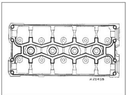
Technical line drawing of a mechanical component with symmetrical slots and mounting holes (no text or symbols)11.35 Apply thin bead of sealant to camshaft carrier mating surfaces along paths shown by heavy black lines - K16 engine
text_image
10 26 22 18 14 9 8 25 21 17 13 7 6 24 20 16 12 3 4 23 19 15 11 H2243G 1 211.36 Camshaft carrier bolt tightening sequence - K16 engine
12 Valve clearances - general information
1 It is necessary for a clearance to exist between the tip of each valve stem and the valve operating mechanism. This allows for expansion of the various engine components as the engine reaches normal operating temperature.
2 On most older engine designs, this meant that the valve clearances (also known as 'tappet' clearances) had to be checked and adjusted regularly. If the clearances were too slack, the engine would be very noisy, its power output would suffer and its fuel consumption would increase. Conversely, if the clearances were too tight, the engine's power output would be reduced and the valves and their seats could be severely damaged.
3 The engines covered in this Manual employ hydraulic tappets which use engine oil pressure to automatically take up the clearance between each camshaft lobe and its respective valve stem. This means that there is no need for regular checking and inspection of the valve clearances, but it is essential that only good quality oil of the recommended viscosity and specification is used in the engine and that this oil is scrupulously changed at the recommended intervals. If this advice is not followed, the oilways and tappets may become clogged with particles of dirt or deposits of burnt engine oil, so that the system cannot work properly. Ultimately, one or more of the tappets may fail and expensive repairs may be required.
4 On starting the engine from cold, there will be a slight delay while full oil pressure builds up in all parts of the engine, especially in the tappets. The valve clearances, therefore, may well rattle for about 10 seconds or so and then quieten. This is a normal state of affairs and is nothing to worry about, provided that all tappets quieten quickly and stay quiet.
5 After the vehicle has been standing for several days, the valve clearances may rattle for longer than usual as nearly all the oil will have drained away from the engine's top end components and bearing surfaces. While this is only to be expected, care must be taken not to damage the engine by running it at high speed until all the tappets are refilled with oil and operating normally. With the vehicle stationary, hold the engine at no more than a fast idle speed (maximum 2000 to 2500 rpm) for 10 to 15 minutes or until the noise ceases. Do not run the engine at more than 3000 rpm until all tappets are fully recharged with oil and all noise has ceased.
6 If the valve clearances are thought to be noisy, or if a light rattle persists from the engine's top end after it has reached normal operating temperature, take the vehicle to a Rover dealer for expert advice. Depending on
the mileage covered and the usage to which each vehicle has been put, some vehicles may be noisier than others. Only a good mechanic experienced in these engines can tell if the noise level is typical for the vehicle's mileage or if a genuine fault exists. If any tappet's operation is faulty, then it must be renewed.
13 Cylinder head - removal and refitting

Note: Due to engine design, it will become very difficult, almost impossible, to turn the crankshaft once the cylinder head bolts have been slackened. The manufacturer states that the crankshaft will be 'tight' and should not be rotated more than absolutely necessary once the head has been removed. If the crankshaft cannot be rotated, then it must be removed for overhaul work to proceed. With this in mind, the crankshaft always must be rotated to the desired position before the bolts are disturbed.
Removal
1 Disconnect the battery negative lead.
2 Drain the cooling system.
3 Remove the camshaft sprocket(s).
4 Unscrew the bolts securing the timing belt upper left-hand (inner) cover to the cylinder head, so that the cover can be pulled away from the cylinder head just far enough for adequate working clearance. Take care not to distort or damage the cover or the timing belt.
5 Remove the cylinder head cover.
6 Disconnect the exhaust system front pipe from the manifold and, where fitted, disconnect or release the lambda sensor wiring so that it is not strained by the weight of the exhaust.
7 Note that the following text assumes that the cylinder head will be removed with both inlet and exhaust manifolds attached. This is easier but makes it a bulky and heavy assembly to handle. If it is wished first to remove the manifolds, proceed as described in the relevant Sections of Chapter 4.
8 On carburettor engines, disconnect the following from the carburettor and inlet manifold as described in the relevant Sections of Chapter 4A:
a) Fuel pump feed hose - plug both openings to prevent loss of fuel and entry of dirt into system.
b) Carburettor idle bypass solenoid wires.
c) Accelerator cable.
d) Choke cable.
e) Vacuum servo unit vacuum hose.
f) Inlet manifold PTC heater wire.
g) Inlet manifold heater temperature switch wiring.
9 On fuel-injected engines, refer to the relevant Sections of Chapter 4B or C, and disconnect or remove all throttle body/fuel rail components appertaining to cylinder head removal, noting the following:
a) The fuel system must be depressurised before any component is disconnected.
b) Plug the open ends of all disconnected pipes to prevent loss of fuel and entry of dirt into system.
c) Discard all sealing washers and O-rings, these must be renewed.
10 Working as described in Chapter 3, disconnect the connector plug from the coolant temperature sensor screwed into the coolant outlet elbow, then disconnect the coolant hoses from the (three) inlet manifold unions and from the coolant outlet elbow.
11 Unclip the engine wiring harness from the inlet manifold or its support stays. Slacken the bolts securing the stays to the manifold, then unbolt the support stays and the carburettor metal overflow pipes from the cylinder block/crankcase.
12 Remove the distributor cap, complete with the spark plug HT leads. Remove the spark plugs.
13 On K16 engines equipped with air conditioning, undo the nuts and bolts securing the heat shields to the rear of the alternator and air conditioning compressor and remove both heat shields. Slacken the two lower alternator mounting bolts then remove the upper mounting bolt and pivot the alternator away from the cylinder head.
14 Working in the reverse of the tightening sequence (see illustrations 13.29a or
13.29b), progressively slacken the ten cylinder head bolts by one turn at a time. A female Torx-type socket (No 12 size) will be required. Remove each bolt in turn and store it in its correct fitted order by pushing it through a clearly-marked cardboard template.
15 The joint between the cylinder head and gasket and the cylinder block/crankcase must now be broken without disturbing the wet liners. Although these liners are better located and sealed than some wet liner engines, there is still a risk of coolant and foreign matter leaking into the sump if the cylinder head is lifted carelessly. If care is not taken and the liners are moved, there is also a possibility of the bottom seals being disturbed, causing leakage after refitting the head.
16 To break the joint, obtain two L-shaped metal bars which fit into the cylinder head bolt holes and gently rock the cylinder head free towards the front of the vehicle (see illustration). Do not try to swivel the head on

natural_image
Line drawing of a mechanical assembly with hands operating a tool (no text or symbols present)13.16 Using two cranked bars to break cylinder head joint
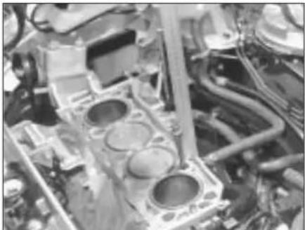
natural_image
Close-up of an engine cylinder head assembly with visible internal components and wiring (no text or symbols)13.20 Checking condition of cylinder head bolt threads - cylinder head removed

natural_image
Close-up of an engine cylinder head with two black arrows pointing to specific boreholes (no text or symbols visible)13.26a Fit new cylinder head gasket on two locating dowels (arrowed) ...
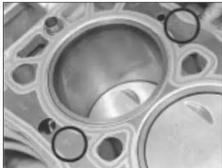
natural_image
Close-up of a mechanical component with circular features and mounting holes (no visible text or symbols)13.26b ... so that TOP mark is upwards and FRONT arrow points to timing belt end
the cylinder block/crankcase as it is located by dowels as well as by the tops of the liners.
17 With the joint broken, lift the cylinder head away, using assistance if possible as it is a heavy assembly, especially if complete with the manifolds. Remove the gasket, noting the two locating dowels, and discard it.
18 Further to the warnings given in the note at the beginning of this Section, do not attempt to rotate the crankshaft with the cylinder head removed, otherwise the wet liners may be displaced. Operations that would normally require the rotation of the crankshaft (eg: cleaning the piston crowns) must be carried out with great care to ensure that no particles of dirt or foreign matter are left behind. If cylinder liner clamps are to be used, they must be clamped in place using

natural_image
Close-up of hands working on an engine block assembly (no visible text or symbols)13.27 Refitting the cylinder head
spacers fitted under the heads of the cylinder head bolts.
19 If the cylinder head is to be dismantled, remove the camshaft(s) then refer to the relevant Sections of Part B of this Chapter.
Refitting
20 Check the condition of the cylinder head bolts, particularly their threads. Keeping all bolts in their correct fitted order, wash them and wipe dry. Check each bolt for any sign of visible wear or damage, renewing as necessary. Lightly oil the threads of each bolt, carefully enter it into its original hole and screw it in, by hand only until finger-tight. Measure the distance from the cylinder block/crankcase gasket surface to under the bolt's head (see illustration).
21 If the distance measured is under 97 mm, the bolt may be re-used. If the distance measured is more than 97 mm, the bolt must be renewed. Considering the task these bolts perform and the pressures they must withstand, owners should consider renewing all the bolts as a matched set if more than one of the originals fail inspection or are close to the limit set.
22 The mating faces of the cylinder head and cylinder block/crankcase must be perfectly clean before refitting the head. Use a hard plastic or wood scraper to remove all traces of gasket and carbon.
23 Check the mating surfaces of the cylinder block/crankcase and the cylinder head for
nicks, deep scratches and other damage. If slight, they may be removed carefully with a file, but if excessive, machining may be the only alternative to renewal.
24 If warpage of the cylinder head gasket surface is suspected, use a straight-edge to check it for distortion. Refer to Part B of this Chapter if necessary.
25 Wipe clean the mating surfaces of the cylinder head and cylinder block/crankcase. Check that the two locating dowels are in position at each end of the cylinder block/crankcase surface.
26 Position a new gasket on the cylinder block/crankcase surface so that its TOP mark is uppermost and the FRONT arrow points to the timing belt end (see illustrations).
27 Refit the cylinder head, locating it on the dowels (see illustration).
28 Keeping all the cylinder head bolts in their correct fitted order, wash them and wipe dry. Lightly oil under the head and on the threads of each bolt, carefully enter it into its original hole and screw it in, by hand only, until finger-tight.
29 Working progressively and in the sequence shown (see illustrations), use first a torque wrench, then an ordinary socket extension bar to tighten the cylinder head bolts through the specified stages. To tighten the bolts through the specified angles, simply use a felt-tip pen or similar to mark the position on the cylinder head of each bolt head's radial mark. The second stage then
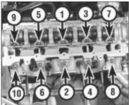
text_image
9 5 1 3 7 10 6 2 4 813.29a Cylinder head bolt tightening sequence - K8 engine
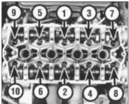
text_image
9 5 1 3 7 10 6 2 4 813.29b Cylinder head bolt tightening sequence - K16 engine
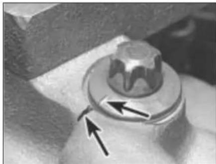
natural_image
Close-up of a mechanical knob with directional arrows indicating movement or force (no text or symbols)13.29c Alignment of bolt head radial marks with cylinder head to establish tightening angles (arrowed)
tightens each bolt through half a turn so that the marks face away from each other and the third stage tightens them through another half-turn so that all the bolt-head marks will then align again with their cylinder head counterparts. If any bolt is overtightened past its mark, slacken it through 90°, then re-tighten until the marks align (see illustration). 30 Refit and tighten the inlet manifold support stay bolts, then secure the engine wiring harness using the clips provided.
31 On K16 engines equipped with air conditioning, refit the alternator mounting bolts and tighten them to the specified torque setting. Refit the compressor and alternator heatshields, tightening their retaining bolts and nuts securely.
32 Connect all disturbed coolant hoses, securing them in position with their retaining clips. Reconnect the coolant temperature sensor wiring.
33 Working as described in Chapter 4, connect or refit all disturbed wiring, hoses and control cable(s) to the inlet manifold and fuel system components, then adjust the choke and or accelerator cable(s).
34 Reconnect the exhaust system front pipe to the manifold and (if applicable) reconnect the lambda sensor wiring.
35 Refit the cylinder head cover, inner timing cover retaining bolts and camshaft sprocket(s).
36 Refit the spark plugs and distributor cap then reconnect the battery negative lead.
37 Refill the cooling system.
14 Sump - removal and refitting

Note: It is essential that new bolts of the Patchlok type are used when refitting the sump.
Removal
1 Disconnect the battery negative lead.
2 Drain the engine oil then clean and refit the engine oil drain plug, tightening it to the specified torque wrench setting. If the engine is nearing its service interval when the oil and filter are due for renewal, it is recommended that the filter is also removed and a new one fitted. After reassembly, the engine can then be replenished with fresh engine oil.
3 Apply the handbrake, then jack up the front of the vehicle and support it on axle stands. Remove the right-hand roadwheel.
4 From underneath the front of the vehicle, slacken and remove the three bolts securing the bumper flange to the body. Remove the seven bolts securing the front undercover panel to the body and remove the panel.
5 Working as described in Chapter 4, disconnect the exhaust system front pipe from the manifold and, where fitted, disconnect or release the lambda sensor

natural_image
Close-up of a hand adjusting a mechanical component with visible bolts and parts (no text or symbols)reach sump bolts
wiring so that it is not strained by the weight of the exhaust.
6 Unscrew the three retaining bolts and remove the flywheel lower cover plate (see illustration).
7 Slacken and remove the bolts securing the anti-beaming bracket to the engine and transmission and remove the bracket.
8 Progressively slacken the sump retaining bolts then remove them along with the anti-beaming bracket support. Make a note of the correct fitted position of the support and of the longer bolts at positions 4, 8 and 12 (see illustration 14.14) to ensure correct refitment on reassembly.
9 Break the joint by striking the sump with the palm of the hand, then lower the sump and withdraw it (see illustration).
10 While the sump is removed, take the opportunity to unbolt the oil pump pickup/strainer pipe and clean it using a suitable solvent. Inspect the strainer mesh for signs of clogging or splitting and renew if necessary.
Refitting
11 Clean all traces of gasket from the mating surfaces of the cylinder block/crankcase and sump, then use a clean rag to wipe out the sump and the engine's interior. If the oil pump pick-up/strainer pipe was removed, fit a new sealing O-ring to its end and refit the pipe, tightening its retaining bolts to the specified torque setting.
12 If the sump gasket is damaged or shows signs of deterioration, then it must be renewed. Fit the gasket to the sump mating
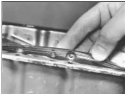
natural_image
Close-up of a hand adjusting a metal component with bolts (no visible text or symbols)with sump mating surface holes
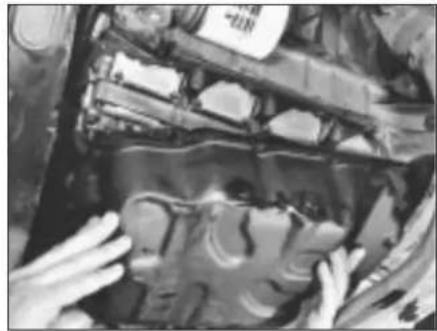
natural_image
Close-up of hands installing or adjusting a mechanical component in a vehicle (no visible text or symbols)14.9 Removing the sump14.6 Remove flywh
surface so that its 7 locating pegs fit into the sump holes (see illustration).
13 Offer up the sump to the cylinder block/crankcase then fit the new sump retaining bolts, not forgetting the anti-beaming bracket support. Tighten the bolts finger-tight only.
14 Working in the sequence shown (see illustration), tighten the sump bolts to the specified torque setting.
15 Refit the anti-beaming bracket and tighten the mounting bolts to the specified torque setting.
16 Install the flywheel lower cover plate and tighten the retaining bolts to the specified torque wrench setting.
17 Reconnect the exhaust system front pipe to the manifold and, where necessary, reconnect the lambda sensor wiring.
18 Refit the undercover panel and wheel, then lower the vehicle to the ground and reconnect the battery negative lead.
19 Replenish the engine oil.
15 Oil pump - removal and refitting

Note: The oil pressure relief valve can be dismantled without removing the oil pump from the vehicle. See Section 16 for details.
Removal
1 Remove the crankshaft sprocket and secure the timing belt clear of the working
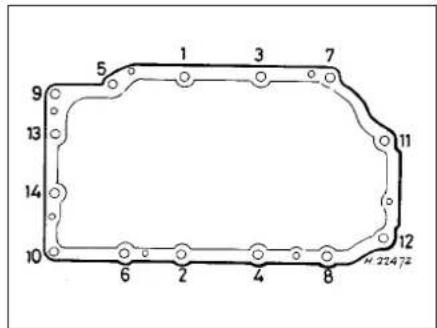
text_image
5 1 3 7 9 13 14 10 6 2 4 8 12 2247214.14 Sump bolt tightening sequence14.12 Sump (
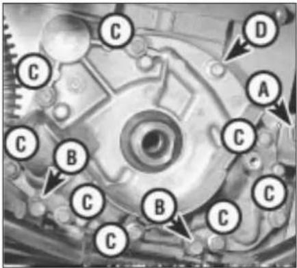
text_image
C D A C B C B C C15.4 Alternator adjuster link nut (A) wiring guide screws (B) oil pump bolts (C) and special oil pump bolt (D)
area so that it cannot be contaminated with oil.
2 Drain the engine oil, then clean and refit the engine oil drain plug, tightening it to the specified torque wrench setting. If the engine is nearing its service interval when the oil and filter are due for renewal, it is recommended that the filter is also removed and a new one fitted. After reassembly, the engine can then be replenished with fresh engine oil.
3 Where necessary, unscrew the alternator adjuster link retaining nut and unbolt the engine wiring harness guide retaining screws, then move the link and guide clear of the oil pump.
4 Unscrew the oil pump retaining bolts, noting the fitted position of the special bolt, and withdraw the oil pump (see illustration). Recover the pump gasket and discard it, then carefully lever the crankshaft right-hand oil seal out of the oil pump. The oil seal should be renewed whenever it is disturbed.
Refitting
5 Thoroughly clean the mating faces of the oil pump and cylinder block/crankcase. Use grease to stick a new gasket in place.
6 Prime the pump before installation by injecting clean engine oil into it and turning it by hand.
7 Offer up the pump, ensuring that its inner

natural_image
Close-up of mechanical components including a spring and bearing assembly (no visible text or symbols)16.4 Unscrewing oil pressure relief valve threaded plug

text_image
② ③ ⑥ ⑤ ⑧ ④ ① ⑦ H2258515.8 Oil pump bolt tightening sequence
gear engages fully on the crankshaft flats, then push the pump fully into position.
8 Refit the pump retaining bolts, ensuring that the special bolt is refitted to its original position. Tighten the retaining bolts to the specified torque setting in the order shown (see illustration).
9 If removed, refit the alternator adjuster link and the engine wiring harness guide, then tighten securely the retaining nut and screws.
10 Fit a new crankshaft right-hand oil seal.
11 Remove all traces of surplus oil then refit the crankshaft sprocket.
12 Replenish the engine oil.
16 Oil pump - dismantling, inspection and reassembly

Note: If oil pump wear is suspected, check the cost and availability of new parts (only available in the form of repair kit LQX 10001) against the cost of a new pump. Examine the pump as described in this Section and then decide whether renewal or repair is the best course of action.
Dismantling
1 Remove the oil pump.
2 Unscrew the Torx screws (size T25) and remove the pump cover plate. Discard the sealing ring.
3 Note the identification marks on the outer rotor then remove both the rotors from the body.

text_image
1 2 H 2247316.5 Oil pressure relief valve assembly
1 Threaded plug
2 Valve spring and plunger
4 The oil pressure relief valve can be dismantled, if required, without disturbing the pump. If this is to be done with the pump in position and the engine still installed in the vehicle, it will first be necessary to jack up the front of the vehicle and remove the right-hand roadwheel to gain access to the valve (see illustration).
5 To dismantle the valve, unscrew the threaded plug and recover the valve spring and plunger (see illustration). Discard the plug sealing washer.
Inspection
6 Inspect the rotors for obvious signs of wear or damage and renew if necessary. If the pump body or cover plate is scored or damaged, then the complete oil pump assembly must be renewed.
7 Using feeler gauge blades of the appropriate thickness, measure the clearance between the outer rotor and the pump body, then between the tips of the inner and outer rotor lobes (a and b respectively) (see illustration).
8 Using feeler gauge blades and a straight-edge placed across the top of the pump body and the rotors, measure the rotor endfloat (c).
9 If any measurement is outside the specified limits, the complete pump assembly must be renewed.
10 If the pressure relief valve plunger is scored, or if it does not slide freely in the pump body bore, then it must be renewed, using all the components from the repair kit.
11 To complete a thorough inspection of the oil pump components, the sump should be removed and the oil pump pick-up/strainer pipe removed and cleaned.
Reassembly
12 Lubricate the pump rotors with clean engine oil and refit them to the pump body,

text_image
Technical diagram showing three labeled mechanical components (a, b, c) with annotations and a scale bar indicating 10.24mm.16.7 Checking oil pump rotors for wear - see text for details
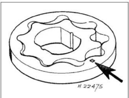
text_image
H 2247516.12 Oil pump outer rotor outside face identifying mark (arrowed)
ensuring that the outer rotor's identification mark faces outwards (see illustration).
13 Fit a new sealing ring to the pump body and refit the cover plate. Apply thread-locking compound to the threads of the cover plate Torx screws and tighten them securely.
14 Check that the pump rotates freely, then prime it by injecting oil into its passages and rotating it. If a long time elapses before the pump is refitted to the engine, prime it again before installation.
15 Refit the oil pressure relief valve plunger, ensuring that it is the correct way up, then install the spring. Fit a new sealing washer to the threaded plug and tighten the plug securely.
17 Crankshaft oil seals - renewal

Right-hand seal
1 Remove the crankshaft sprocket and secure the timing belt clear of the working area so that it cannot be contaminated with oil.
2 Punch or drill two small holes opposite each other in the seal. Screw a self-tapping screw into each and pull on the screws with pliers to extract the seal.
3 Clean the seal housing and polish off any burrs or raised edges which may have caused the seal to fail in the first place.
4 Lubricate the lips of the new seal with clean engine oil and drive it into position until it seats on its locating shoulder. Use a suitable tubular drift, such as a socket, which bears only on the hard outer edge of the seal. Take care not to damage the seal lips during fitting. Use either grease or a thin layer of insulating tape to protect the seal lips from the edges of the crankshaft flats but be careful to remove all traces of tape and to lubricate the seal lips if the second method is used. Note that the seal lips should face inwards.
5 Wash off any traces of oil, then refit the crankshaft sprocket.
Left-hand seal
6 Remove the flywheel.

natural_image
Close-up of a mechanical assembly with gears and shafts (no visible text or symbols)18.2 Using fabricated tool to lock flywheel in position
7 Taking care not to mark either the crankshaft or any part of the cylinder block/crankcase, lever the seal evenly out of its housing.
8 Clean the seal housing and polish off any burrs or raised edges which may have caused the seal to fail in the first place.
9 Lubricate with grease the lips of the new seal and the crankshaft shoulder, then offer up the seal to the cylinder block/crankcase.
10 Ease the sealing lip of the seal over the crankshaft shoulder by hand only, then press the seal evenly into its housing until its outer flange seats evenly on the housing lip. If necessary, a soft-faced mallet can be used to tap the seal gently into place.
11 Wash off any traces of oil, then refit the flywheel.
18 Flywheel - removal, inspection and refitting

Removal
1 Remove the gearbox and the clutch assembly.
2 Prevent the flywheel from turning by locking the ring gear teeth (see illustration) or by bolting a strap between the flywheel and the cylinder block/crankcase.
3 Slacken and remove the flywheel retaining bolts and discard them The bolts must be renewed whenever they are disturbed.
4 Remove the flywheel. Do not drop it, as it is very heavy.
Inspection
5 If the flywheel's clutch mating surface is deeply scored, cracked or otherwise damaged, then the flywheel must be renewed, unless it is possible to have it surface ground. Seek the advice of a Rover dealer or engine reconditioning specialist.
6 If the ring gear is badly worn or has missing teeth, then it must be renewed. This job is best left to a Rover dealer or engine reconditioning specialist. The temperature to which the new ring gear must be heated for installation (350°C - shown by an even light blue colour) is critical and, if not done
accurately, the hardness of the teeth will be destroyed.
7 Examine the reluctor ring (fitted to the rear of the flywheel) for signs of damage and check that it is securely fastened by the two retaining screws. If the reluctor ring is damaged, then it must be renewed.
Refitting
8 Clean the mating surfaces of the flywheel and crankshaft. Clean any remaining adhesive from the threads of the crankshaft threaded holes by making two saw cuts at opposite points along the (carefully-cleaned) threads of one of the original flywheel bolts and screwing it into each hole in turn. Do not use a tap to clean the threads in this way.
9 Position the flywheel over the crankshaft's locating dowel, press it into place and fit six new bolts.
10 Lock the flywheel using the method employed on dismantling, then tighten the retaining bolts to the specified torque wrench setting.
11 Refit the clutch, then remove the locking tool and refit the gearbox.
19 Engine/gearbox mountings - inspection and renewal

Inspection
1 If improved access is required, raise the front of the vehicle and support it securely on axle stands.
2 Check the mounting rubber to see if it is cracked, hardened or separated from the metal at any point. Renew the mounting if any such damage or deterioration is evident.
3 Check that all mounting fasteners are securely tightened. Use a torque wrench to check, if possible.
4 Using a large screwdriver or a pry bar, check for wear in the mounting by carefully levering against it to check for free play. Where this is not possible, enlist the aid of an assistant to move the engine/gearbox unit back and forth or from side to side while you watch the mounting. While some free play is to be expected even from new components, excessive wear should be obvious. If excessive free play is found, check first that the fasteners are correctly secured, then renew any worn components as described below.
Renewal
Right-hand mounting
5 Disconnect the battery negative lead.
6 To improve access to the mounting, remove the expansion tank mounting bolts then free the coolant hose from any relevant retaining clips and position the tank clear of the engine. On models equipped with power-assisted steering, undo all the power steering hose retaining clamp bolts then slide the fluid

natural_image
Close-up of a vehicle's undercarriage showing a white rectangular object mounted on a vehicle (no visible text or symbols)19.7a Use trolley jack with wooden spacer to adjust height of engine/gearbox unit
reservoir out of its retaining clip and position it clear of the timing belt covers. Take great care not to place any undue strain on hoses and mop up any spilt fluid immediately.
7 Support the weight of the engine/gearbox unit by using a trolley jack, with a wooden spacer to prevent damage to the sump. Unscrew the mounting through-bolt and nut and the mounting to bracket nuts. Remove the mounting, noting the two rubber washers (see illustrations).
8 Where necessary, unscrew the retaining bolts and remove the bracket from the cylinder block/crankcase.
9 Check carefully for signs of wear or damage on all components and renew them where necessary.
10 On reassembly, refit the bracket to the
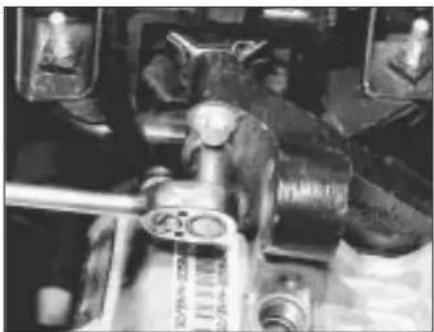
natural_image
Close-up of mechanical components with no visible text or symbols19.18 Slacken and remove gearbox bracket-to-mounting bolts...
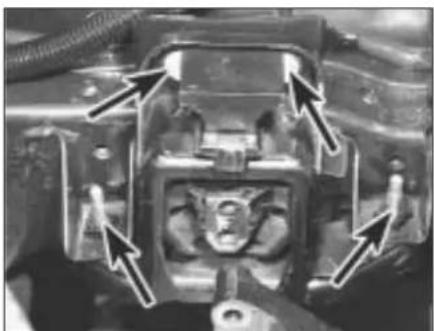
natural_image
Close-up of a mechanical component with arrows pointing to features (no visible text or symbols)four left-hand mounting-to-body bolts (arrowed) ...
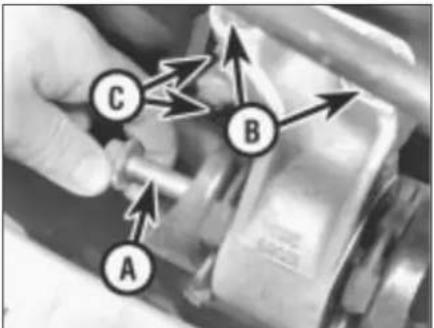
text_image
A B C19.7b Right-hand mounting through-bolt (A), mounting-to-bracket nuts (B), bracket-to-cylinder block/crankcase bolts (two arrowed - C)
cylinder block/crankcase and tighten the retaining bolts to the specified torque setting.
11 Locate the rubber washers on the mounting, one on each side of its centre boss, then refit the mounting to the bracket and tighten the retaining nuts, finger-tight only.
12 Using the trolley jack to position the engine unit at the correct height, refit from rear to front the mounting-to-body through-bolt, ensuring that the rubber washers are correctly seated, then refit the nut (see illustration).
13 Tighten the mounting to bracket nuts and the through-bolt to the specified torque wrench settings, then lower and remove the jack.
14 Where necessary, refit the power steering fluid reservoir to its mounting bracket and secure the hydraulic hose clamps in position with the retaining bolts.
15 Refit the coolant expansion tank and tighten the mounting bolts securely. Secure the coolant hose in position with any necessary retaining clips and reconnect the battery negative lead.
Left-hand mounting
16 Disconnect the battery negative lead then disconnect the clutch cable.
17 To improve access to the mounting, unclip the engine wiring harness and position it clear of the mounting.
18 Support the weight of the engine/gearbox
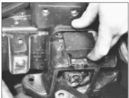
natural_image
Close-up of a hand adjusting a mechanical component with visible bolts and mounting holes (no text or symbols)19.19b ... and remove mounting19.19a
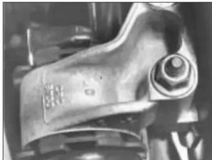
natural_image
Close-up of a mechanical component with no visible text or symbols19.12 Check rubber washers are correctly installed before tightening through-bolt nut
unit by using a trolley jack, with a wooden spacer to prevent damage to the gearbox casing. Slacken and remove the two bolts securing the gearbox bracket to the mounting (see illustration).
19 Lower the engine/gearbox unit, then remove the four bolts securing the mounting to the body and manoeuvre the mounting out of position. If required, slacken and remove the two bolts which secure the bracket to the gearbox and remove the bracket (see illustrations).
20 Although the mounting rubber is secured by two nuts to a metal outer section, the two parts can be renewed only as a complete assembly. Check all components carefully for signs of wear or damage and renew where necessary.
21 On reassembly, refit the bracket to the gearbox and tighten the retaining bolts to the specified torque setting.
22 Manoeuvre the mounting into position then refit the retaining bolts and tighten them to the specified torque setting.
23 Use the trolley jack to raise the gearbox to the correct height, then refit the mounting bracket to mounting bolts and tighten them to the specified torque setting. Refit the wiring harness to its retaining clip.
24 Refit the clutch cable and reconnect the battery negative lead.
Rear mounting
25 Apply the handbrake then jack up the
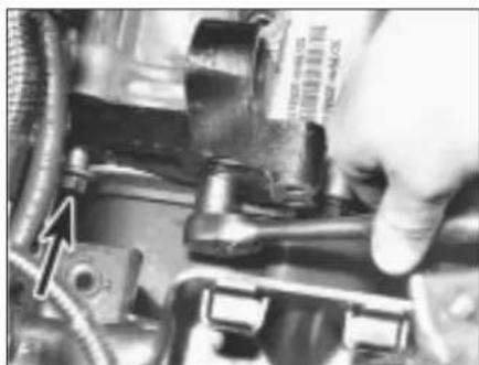
natural_image
Close-up of a hand adjusting a mechanical component with visible parts and a tool (no text or symbols).19. 1 Ben Geardrogelbacked risl retaliored by two bolts (one arrowed)