PDSX 6232/1 - Dishwasher PRIVILEG - Free user manual and instructions
Find the device manual for free PDSX 6232/1 PRIVILEG in PDF.

User questions about PDSX 6232/1 PRIVILEG
0 question about this device. Answer the ones you know or ask your own.
Ask a new question about this device
Download the instructions for your Dishwasher in PDF format for free! Find your manual PDSX 6232/1 - PRIVILEG and take your electronic device back in hand. On this page are published all the documents necessary for the use of your device. PDSX 6232/1 by PRIVILEG.
USER MANUAL PDSX 6232/1 PRIVILEG
natural_image
Close-up of three wooden clothespins with metal clips, no text or symbols visibleInstallations- och underhållsanvisningar Instrukser for installasjon og vedlikehold Vedledning for installation ogvedligeholdelse Asennus- ja huolto-ohjeet Instruções para a instalação e a manutenção

natural_image
Black and white photo of two glass bottles with black lids, one partially filled with a white container (no visible text or symbols)
natural_image
Close-up of several empty glasses with blurred background (no text or symbols visible)
natural_image
Close-up of a white industrial or laboratory device with perforated surface and mounting bracket (no visible text or symbols)- Connection to the mains water supply must be carried out by a qualified technician in compliance with the manufacturer's instructions and applicable local safety regulations.
- All local water board regulations must be complied with. Water supply pressure: 0.03 - 1.0 MPa.
- The inlet hose must be securely clamped to the water tap to prevent leaks.
- The inlet water temperature varies according to the model installed. Inlet hose marked: "25°C Max": up to a maximum of 25°C. Other models: up to a maximum of 60°C.
- Depending on the appliance model, the solenoid valve of the inlet hose will be activated by the mains voltage (see assembly instructions).
- Make sure the inlet and drain hoses are kink-free and are not crushed.
- Fix the drain hose to the siphon with a clamp to prevent it from coming off during operation.
- When installing the appliance, make sure water can drain freely (remove the siphon plug if necessary).
- Do not use old or damaged hoses. Use only the hoses provided or new ones, which can be requested from the After-Sales Service.
- If hoses are not long enough, contact your local dealer.
- Do not cut hoses and, in the case of appliances fitted with a waterstop system, do not immerse the plastic casing containing the inlet hose in water.
- Before using the appliance for the first time, check the water inlet and drain hose for leaks.
2. Electrical Connection
- All local electricity board regulations must be complied with.
- Voltage information is shown on the rating plate mounted inside the door on the right hand side.
- The appliance must be earthed as prescribed by law.
- Do not use extension leads or multiple adapters.
- If the power cable is damaged, replace it with an identical one. The power cable must only be replaced by a qualified technician.
- After appliance installation, the mains plug must be easily accessible so that the appliance can be unplugged if necessary at any time.
For Austria:
If a fault current switch is fitted upline of the appliance, this must be pulse current-sensitive.
3. Assembly instructions
- During assembly the appliance must be unplugged from the mains.
- Set any electrical screwdrivers to a low torque.
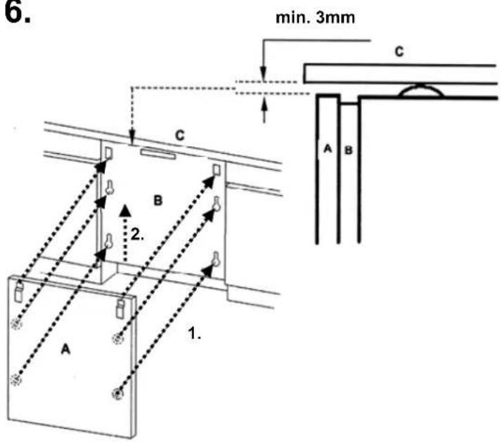
- Leave a gap of at least 3 mm between the top edge of the wooden door and the worktop.
- Do not seal the gaps between adjacent units and the worktop (for example with silicone).
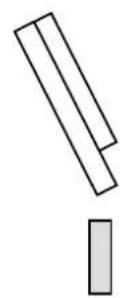
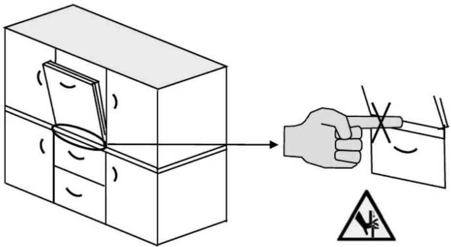
- Attention: when transporting and assembling the appliance, always wear gloves to protect fingers / hands from sharp edges and corners.
- If the appliance is installed at the end of a row of units, making the side panel accessible, the hinge area must be covered to prevent any risk of crushing (cover available from After-sales Service).
- Be careful with uneven installation surfaces: Carefully push the dishwasher with feet unscrewed under the worktop.
- After fitting the plinth and decor panel and before opening the door, evaluate whether the plinth needs to be cut and, if so, how much (see assembly instructions) in order to avoid any damage.
- The sharp edges of the unit and the plinth must be protected from humidity (with insulating material, for example silicone, not included with the appliance).
4. General indications
- The appliance must only be used in the household and according its purpose.
- Do not use the dishwasher until it has been fully assembled.
- Do not use the dishwasher if it has been damaged in transit. Contact After-Sales Service or your local dealer.
Before carrying out any cleaning or maintenance operations, unplug the appliance and turn off the water tap. The same applies in the event of a malfunction. - Do not use abrasive products or alcohol on the control panels.
- All sizes in this maintenance and installation manual are given in millimetres.
- Packaging varies according to the dishwasher model.
ELECTRICAL CONNECTION
I) For Great Britain only
Warning - this appliance must be earthed
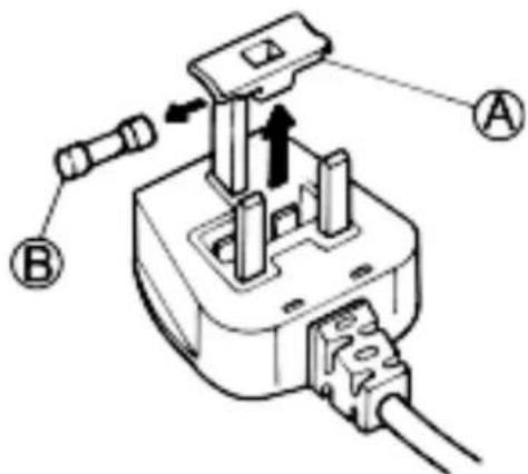
Fuse replacement
If the mains lead of this appliance is fitted with a BS 1363A 13amp fused plug, to change a fuse in this type of plug use an A.S.T.A. approved fuse to BS 1362 type and proceed as follows:
I. Remove the fuse cover (A) and fuse (B).
2. Fit replacement I3A fuse into fuse cover.
3. Refit both into plug.
Important:
The fuse cover must be refitted when changing a fuse and if the fuse cover is lost the plug must not be used until a correct replacement is fitted.
Correct replacement are identified by the colour insert or the colour embossed in words on the base of the plug.
Replacement fuse covers are available from your local electrical store.
2) For the Republic of Ireland only
The information given in respect of Great Britain will frequently apply, but a third type of plug and socket is also used, the 2-pin, side earth type.
3) Socket outlet / plug (valid for both countries)
If the fitted plug is not suitable for your socket outlet, please contact Whirlpool Service for further instruction. Please do not attempt to change plug yourself. This procedure needs to be carried out by a qualified Whirlpool technician in compliance with the manufactures instructions and current standard safety regulations.
text_image
Technical diagram of a plug electrical socket with labeled components A and B, showing internal wiring and mounting points.1. Branchements hydriques
.הכלההוּרָהוּרָהוּרָהוּרָהוּרָהוּרָהוּרָהוּרָהוּרָהוּרָהוּרָהוּרָהוּרָהוּרָהוּרָה
-
-
-
-
text_image
Technical diagram showing airflow or fluid flow through a pipe system with labeled component '1'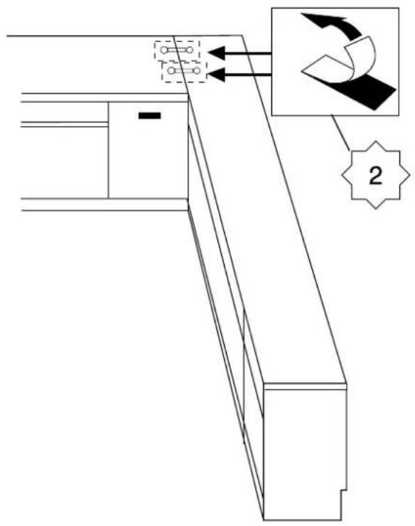
text_image
Technical diagram showing a cabinet or shelf with labeled components and directional arrows, including a magnified inset of a curved component.
text_image
820 - 900 mm 820 - 850 mm 850 - 900 mm 4X 1X 1X 3 + + 2X 2X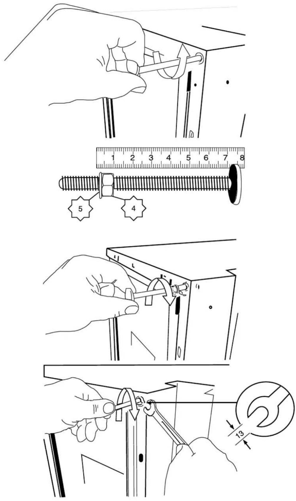
text_image
Technical diagram showing steps to adjust a screw with a wrench, including magnified views and measurement scale.850 - 900 mm

flowchart
graph TD
    A["Start"] --> B["Switching Tool"]
    B --> C["Close-up of Panel"]
    C --> D["~20x"]
    D --> E["Switching Component"]
    E --> F["Close-up of Panel"]
    F --> G["Switching Component"]
    G --> H["~20x"]
    H --> I["Switching Component"]
    I --> J["Close-up of Panel"]

text_image
MIN 10 mm p=0,3 - 10 bar (0,03 - 1,0 MPa) ~1200 mm ~1500 mm ~1600 mm min. 400mm min. 400mm MIN.10 mm 6
text_image
Technical diagram illustrating a mechanical assembly with labeled parts and motion indicators, including a 4x/2x ratio adjustment and numbered components.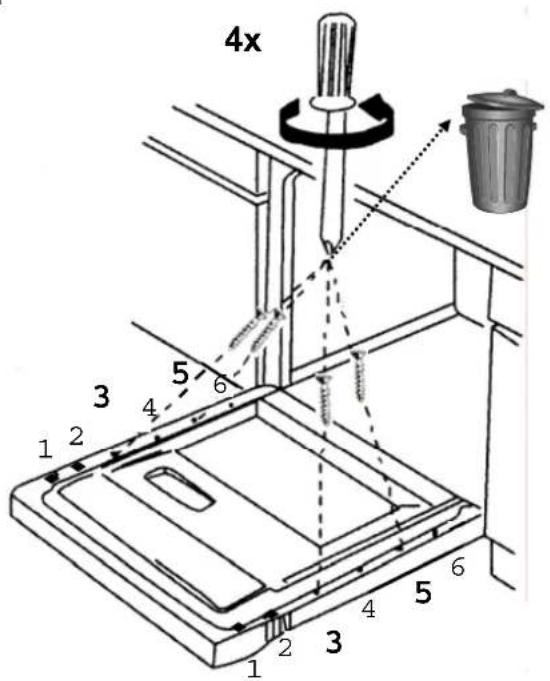
text_image
4x 1 2 3 4 5 6 1 2 3 4 5 6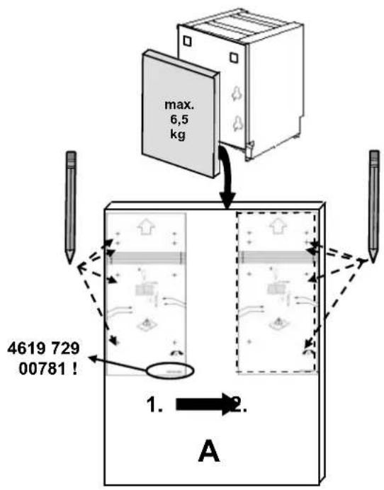
text_image
max. 6,5 kg 4619 729 00781 ! 1. → 2. A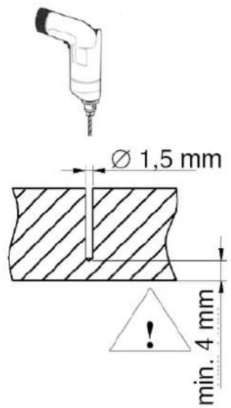
text_image
Ø 1,5 mm min. 4 mm
text_image
max. 6,5kg 16-22,6mm 4x 8 2x 11 A 4x 7 4x 10 592 / 594mm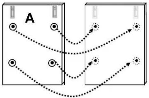
flowchart
graph TD
    A["Process A"] --> B["Process B"]
    B --> C["Output Point 1"]
    B --> D["Output Point 2"]
    B --> E["Output Point 3"]
    style A fill:#f9f,stroke:#333
    style B fill:#ccf,stroke:#333
text_image
6. min. 3mm C A B 1. 2. B C
text_image
A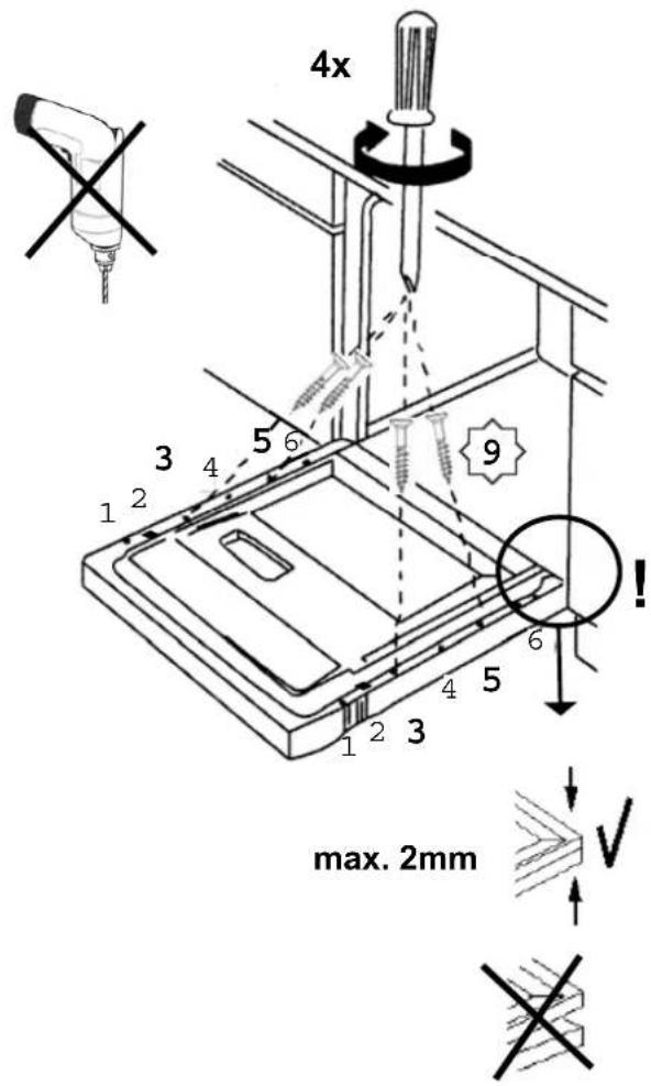
text_image
4x 3 1 2 4 5 6 9 1 2 3 4 5 6 max. 2mm V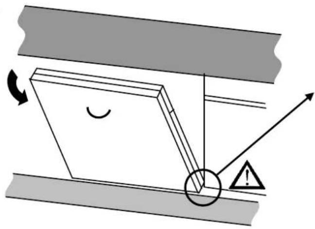
natural_image
Diagram of a mechanical or electrical component with directional arrows and warning symbols (no readable text or labels)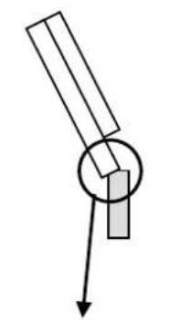
natural_image
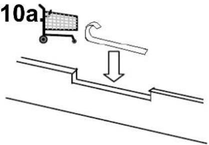
Simple line drawing of a mechanical lever system with a circular component and downward arrow (no text or symbols)10a./10b.
√

text_image
60510b.10a)
text_image
10a)
text_image
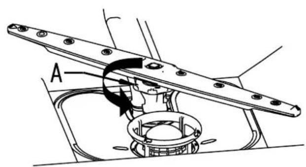
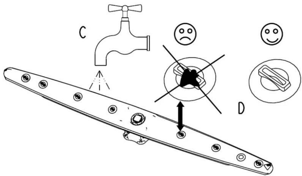
Diagram illustrating a hand holding a tool to cut a box, with warning symbol and safety warning label| D | Wartung und Reinigung |
| GB | Maintenance and Cleaning |
| F | Entretien et nettoyage |
| NL | Onderhoud en reiniging |
| E | Limpieza y conservación |
| P | Manutenção e limpeza |
| I | Manutenzione e pulizia |
| GR | Συντήρηση και καθαρισμός |
| S | Skötsel och rengöring |
| N | Pleie og rengjøring |
| DK | Vedligeholdelse og rengöring |
| FIN | Huolto ja puhdistus |
| PL | Konserwacja i czyszczenie |
| CZ | Üdržba a čištění |
| SK | Üdržba a čistenie |
| H | Karbantartás és tisztítás |
| RUS | Чистка и обслуживание |
| BG | Почистване и поддръжка |
| RO | İntreținerea și curățarea |
| HR | Održavanje i čišćenje |
| TR | Bakım ve temizlik |
| Arabic | الصيانة والënظيف |
| Hebrew | ### |
| KO | 유지보수 및 청소 |
natural_image
Technical line drawing showing a faucet and its internal structure with spray pattern (no text or symbols)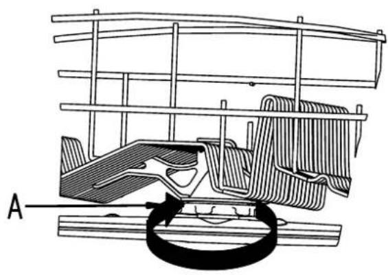
natural_image
Technical diagram of a mechanical assembly with labeled component A (no text or symbols present)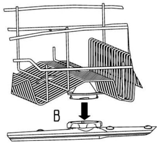
natural_image
Technical line drawing of a mechanical assembly with a base and component, no visible text or symbols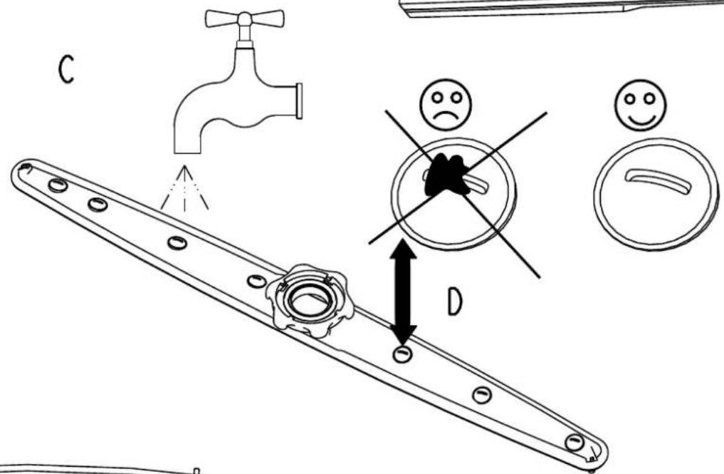
text_image
C D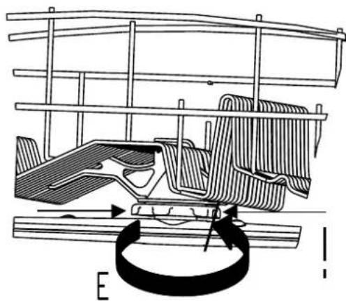
natural_image
Technical line drawing of a mechanical assembly with no visible text or symbols
natural_image
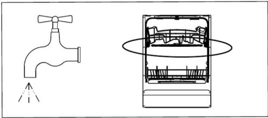
Diagram showing a faucet spraying water onto a shared air vent (no text or labels)1.
text_image
A
text_image
B2.
text_image
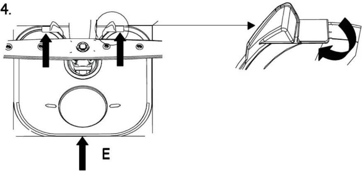
Diagram illustrating a mechanical component with labeled parts and visual indicators including a faucet, sad face, and smiling face.3.
text_image
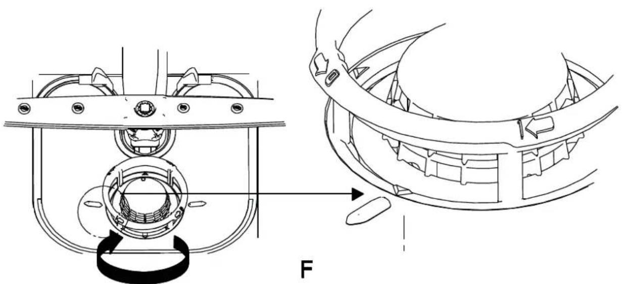
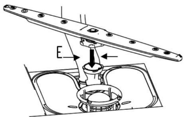
E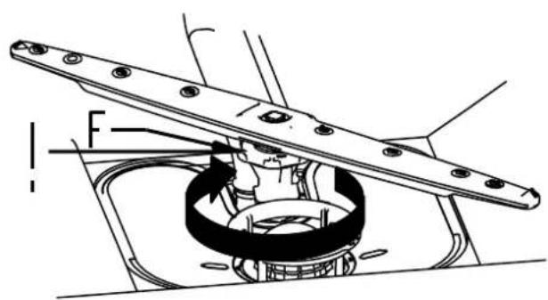
natural_image
Technical diagram of a mechanical assembly with no visible text or symbols
natural_image
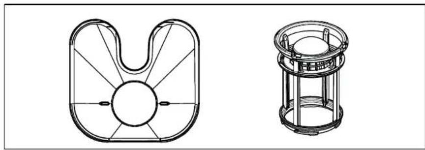
Three technical line drawings of faucet, fan, and cylindrical device (no text or symbols)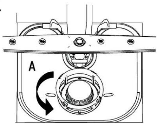
text_image
A
natural_image
Technical line drawing of a mechanical assembly with labeled component B and directional arrow (no text or symbols beyond labels)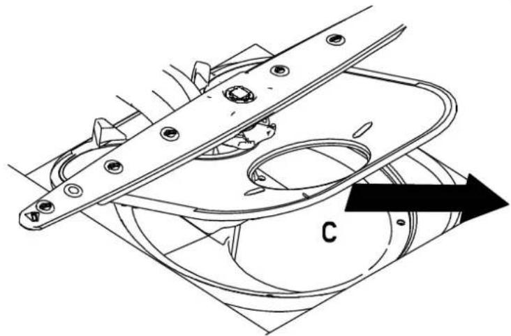
natural_image
Technical line drawing of a mechanical component with labeled part 'C' and directional arrow (no text or symbols beyond label)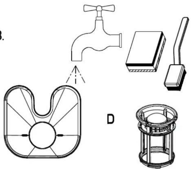
natural_image
Technical line drawings of household appliances including a faucet, door, and storage unit (no text or labels)