tiptronic 1069 - Sewing machine PFAFF - Free user manual and instructions
Find the device manual for free tiptronic 1069 PFAFF in PDF.

User questions about tiptronic 1069 PFAFF
0 question about this device. Answer the ones you know or ask your own.
Ask a new question about this device
Download the instructions for your Sewing machine in PDF format for free! Find your manual tiptronic 1069 - PFAFF and take your electronic device back in hand. On this page are published all the documents necessary for the use of your device. tiptronic 1069 by PFAFF.
USER MANUAL tiptronic 1069 PFAFF
text_image
needle down sew slow basting stitch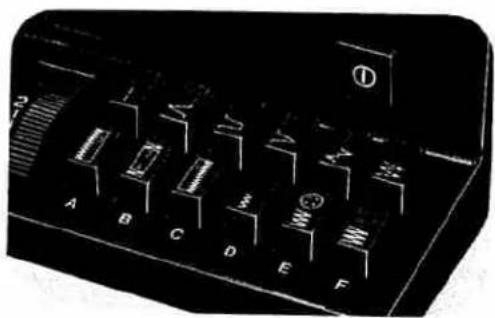
natural_image
Close-up of a black electronic control panel with labeled buttons (A–F) and a handle, no readable text or symbols beyond labels.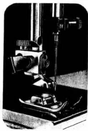
natural_image
Black-and-white photo of a vintage scientific instrument with a central lever and base mount (no visible text or symbols)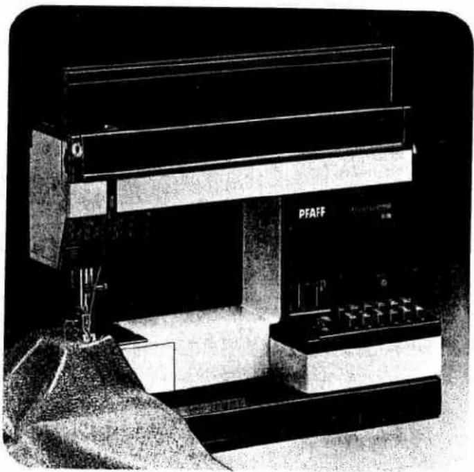
natural_image
Black-and-white photo of a PFAFF industrial machine with control panel and mechanical components (no visible text or symbols)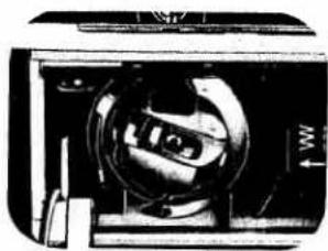
natural_image
Close-up of a mechanical device with internal components and no visible text or symbolsFold this page out
Index Page 2
Accessory box 2
Accessory compartment 16.17
Basting 7
Bobbin 7.8
Bobbin case 8
Bobbin thread 20.21
Buttonholing ........ 1
Carrying case 1
Carrying handle 22
Cleaning 3
Electrical connection 16.17
Electronic bobbin thread monitor 16.17
Electronic top speed selector 12
Finger-tip stitch buttons ....
Foot control 23
Fuse 22
Light bulb 15
Machine feed 15
Needle 16.17
Needle position 22
Oiling 9
Presser bar lifter 11
Reverse sewing 23
Safety rules 18.19
Sewing feet 5
Sewing mechanism 4
Slot-threading 20
Special sewing feet 4
Spool of thread 11
Stitch length 26-29
Stitch program chart 14
Straight-stitch needle position 13
Stretch stitches ....
Top cover
Thread cutter 10
Thread tensions 24 2
Trouble shooting
Upper threading 1
Utility stitches 14
Utility/stretch stitch combinations ....
Winding
Work support ....
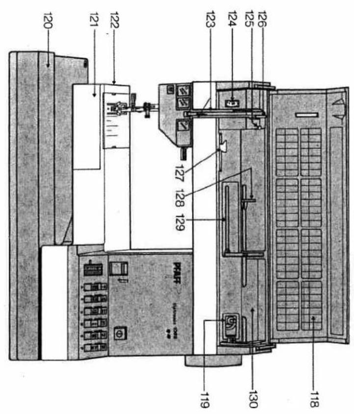
text_image
120 121 122 123 124 125 126 130 118 127 128 129 PAP PAP® (PAP-0000-0000) 119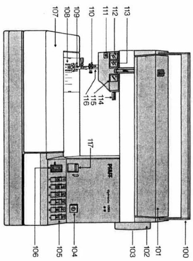
text_image
100 101 102 103 104 105 106 107 108 109 110 111 112 113 PAPT 114 115 116(swing-out)
128 Swing pool holder with unreeling disc
129 Sewing pool holder (swing-up)
126 Take-up lever
127 Bobbin winder thread guide
125 Bobbin winter thread guide
Needle thread tension
123 Threading slots
122 Free arm
hook
120 Base plate
121 Free arm cover, enclosing sewing
119 Bobbin winter
117 Reverse-feed control
118 Stitch program chart
116 Presser bar with thread cutter
115 "Basting stitch" button
114 Presser bar filter
113 "Sev slow" button
112 "Needle down" button
111 Bobbin thread indicator light
110 Needle holder with set screw
foot
109 Sewing foot holder with sewing
108 Needle plate
accessory box and compartment
107 Detachable work support with
106 Stitch length control
105 Finger-tip stitch buttons
104 Master switch
103 Stop motion knob
102 Hand wheel
101 Hidden top cover
100 Carrying Handle
100 Carrying Handle
100 Carrying handle
The Ground Truth image displays a single, solid horizontal line. According to Rule 2 (UNDERSCORE & LINE RULES), this is a stylistic or background line, not a placeholder underscore. Therefore, the OCR result must ignore it and output nothing or only meaningful text. The provided OCR content is "____", which consists of four underscores. This is an incorrect interpretation of the line as a placeholder, violating the rule that stylistic lines must be ignored. The OCR has hallucinated placeholder underscores where none should exist in the GT. Hence, the OCR result is inconsistent with the Ground Truth.
[Non-Text]
[Non-Text]
[Non-Text]
[Non-Text]
[Non-Text]
[Non-Text]
CUL DUR
are omitted, on Model 106 / parts III, IIZ
On Model 1047 parts 111, 112, 113 and 115
- Be careful when sewing that
Parts of your sewing machine
Please note: When a 13-ampere plug is used a 3-ampere fuse has to be fitted.
As the colours of the wires in the mains lead of this appliance may not correspond with the coloured marking identifying the terminals in your plug, proceed as follows: The wire which is coloured blue must be connected to the terminal which is marked with the letter N or coloured black. The wire which is coloured brown must be connected to the terminal which is marked with the letter L or coloured red.
IMPORTANT Valid for United Kingdom only The wires in this mains lead are coloured in accordance with the following code: Blue: Neutral Brown: Live
- Be careful when sewing that your fingers will not be injured by the needle.
- Make sure you pull out the pow-
- Be sure to use only a 15-watt machine for a while.
- Interrupt sewing and leave the intercept, when you have to machine, or when you clean and oil the foot, bobbin or needle plate, when you clean and how to change fuse, needle, sewing underarming
- Light build in the sewing lamp.
Some safety rules
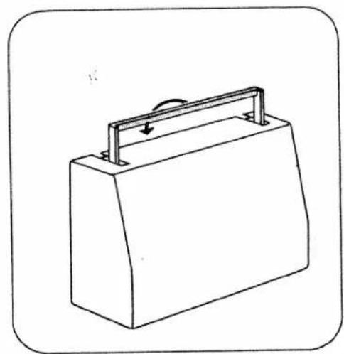
Removing the carrying case cover
To lift off the carrying case cover, fold the handle to the rear, as indicated by an arrow.
Then lift the cover off.
Opening the hinged top cover
Swing cover 101 backwards (N).
A stitch program chart is found on the inside of this cover.
Removing and opening the detachable work support
Reach under the detachable work support with your left hand (0), swing it out toward the left (P), and lift it out (Q). Then open its lid (R). Inside the work support is a removable accessory box with space for additional accessories underneath.
natural_image
Line drawing of a rectangular box with a handle and arrow indicating rotation (no text or symbols)
natural_image
Technical line drawing of a mechanical device with internal components and a labeled section 'N' (no text or symbols on the diagram itself)
natural_image
Technical line drawing of a mechanical component with two upward arrows indicating force or movement (no text or symbols present)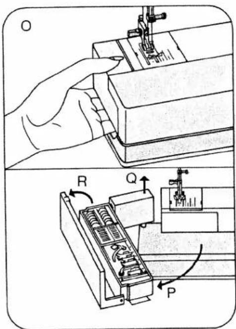
text_image
Technical diagram showing a hand operating a sewing machine with labeled parts R, Q, and P, including mechanical components.Accessory box and accessory compartment
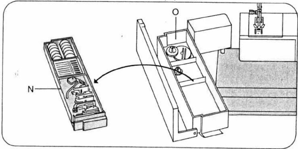
Open the detachable work support and take out accessory box N. There is an additional accessory compartment underneath.
III. P shows how the snap-on sewing feet 0 to 6, the needles and the bobbins fit into the box.
0 Darning foot
4 Blindstitch foot
1 Standard sewing foot
5 Zipper foot
2 Clear-view foot
6 Buttonhole foot
3 Hemming foot
Electrical connection and foot control 1067/1069 (see left ill. on page 3)
Connect the power cord as follows: Push plug N into the machine socket and plug O into the wall socket. Pull the cord out of the foot control (P). Place the foot control under the table, and push plug R into socket S on the machine. Then press master switch button 104. Your machine is now ready for sewing. Press down the foot control. The machine starts sewing. The more you press down the pedal, the faster the machine runs.
As soon as the Model 1069 machine stops, the needle automatically returns to its "up" position.
text_image
Technical diagram showing a mechanical assembly with labeled components and directional arrow indicating transformation or assembly.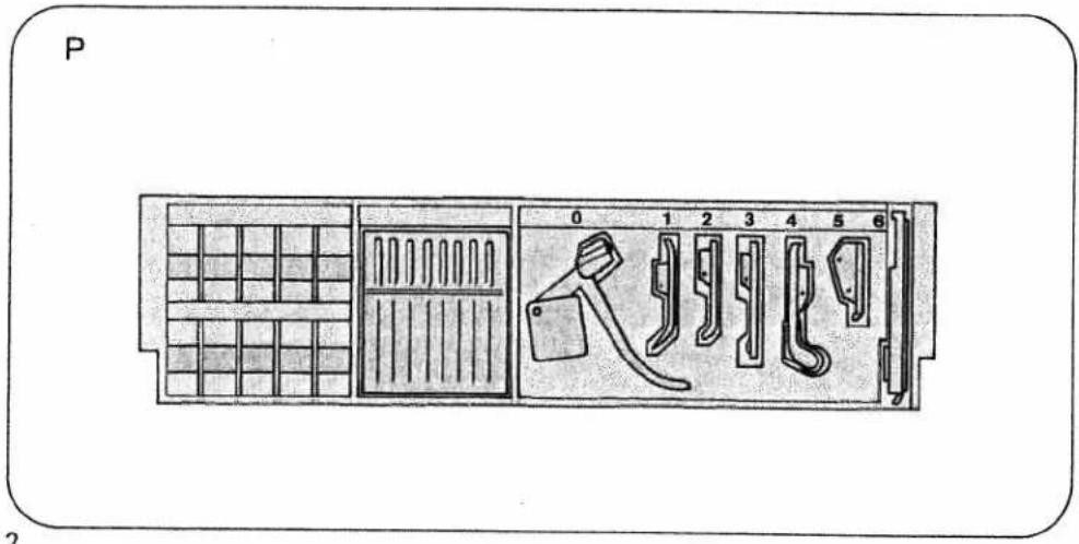
text_image
P 0 1 2 3 4 5 6 2To replace the cord in the foot control, pull it slightly, the release it. It will rewind into the foot control automatically. The cord must not twist as it runs into the control.
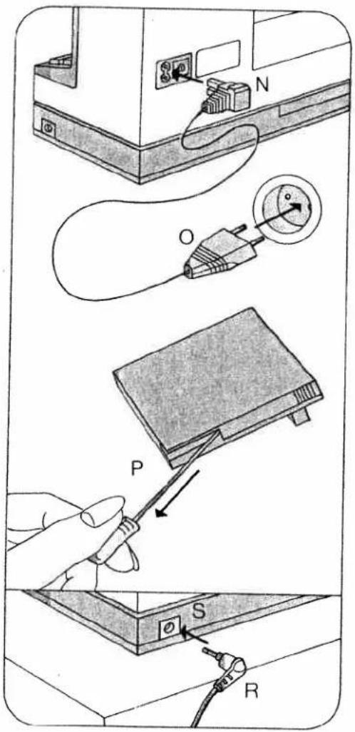
Electrical connection and foot control 1047 (see ill. at right)
Push plug O into the machine socket and plug P into the wall socket. Press master switch button 104. Your machine is now ready for sewing.
Place the foot control under the table and press down the foot pedal. The machine starts sewing. The more you press down the pedal, the faster the machine runs.
Electronic foot control (R):
Position ▶ = half the top speed Position ◀◀ = full top speed
Before you put the machine away after sewing, replace the foot control in the machine (N).
text_image
Diagram illustrating cable installation steps with labeled components: power outlet, cable connector, switch, and cable terminal.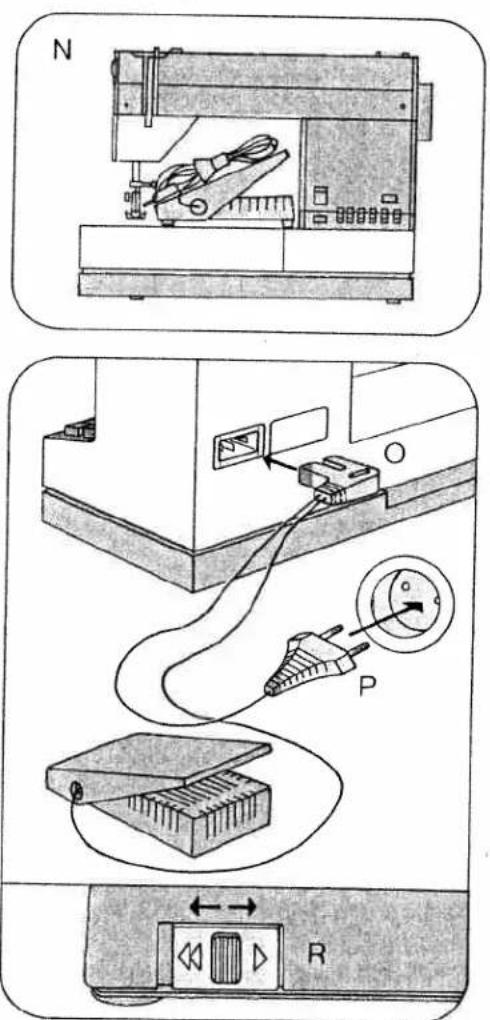
text_image
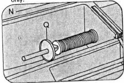
Technical diagram showing three steps of a device connection: battery, switch, and power plug with labeled ports.Placing spool of thread on pin
Load thread reel with diagonal cut for end of thread facing to right.
N Small spools of thread: use small or medium unreeling disc.
Push the spool of thread onto the spool pin and place unreeling disc Q in front of the spool.
O Large spools of thread: use large unreeling disc.
Push the spool of thread onto the spool pin and place unreeling disc R in front of the spool.
P Second spool holder: use small spools of thread and small unreeling discs only.
natural_image
Mechanical assembly diagram showing a spring-loaded component with a shaft and housing (no text or labels)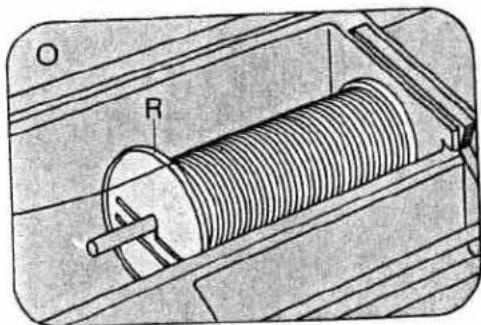
natural_image
Technical illustration of a solenoid coil mounted on a housing, showing internal components and no text or symbols.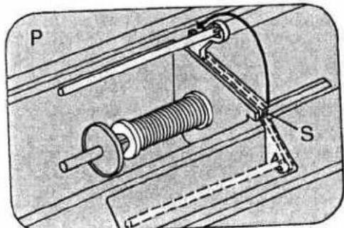
natural_image
Mechanical assembly diagram showing a spring-loaded component with labeled parts P and S (no text or symbols beyond labels)Seize the spool holder by lug S and swing it backwards as far as it will go. It is used for bobbin winding and two-needle sewing.
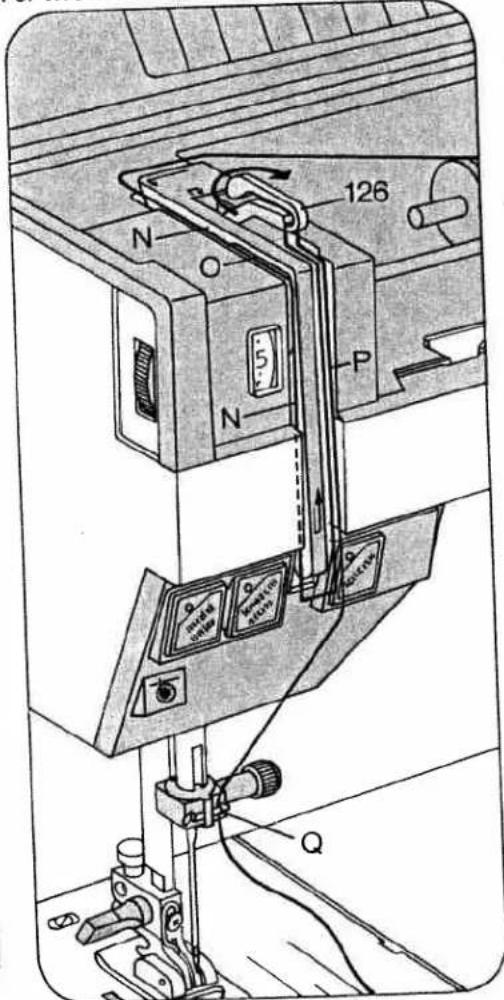
Upper threading
For threading, both the needle and the take-up lever must be in their "up" position.
Raise the sewing foot. Pull the thread from the spool and draw it into slot N (to the left of guide O), from below into slot P and take-up lever 126.
Then draw it back into slot P and into the right thread guide Q on the needle holder. For two-needle sewing, draw one thread
text_image
126 N O 5 P N Qinto the slot to the left of guide O and the other to the right of the guide. One of the threads is then pulled into the right thread guide, the other into the left thread guide on the needle holder.
Threading the needle
Thread the needle from front to back.
Disengaging the sewing mechanism
Hold the hand wheel steady and turn the stop motion knob towards you. This disengages the sewing mechanism. To re-engage the sewing mechanism turn the stop motion knob away from you.
natural_image
Technical line drawing of a sewing machine with needle and clamped parts (no text or symbols)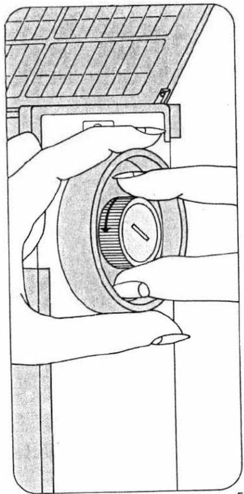
natural_image
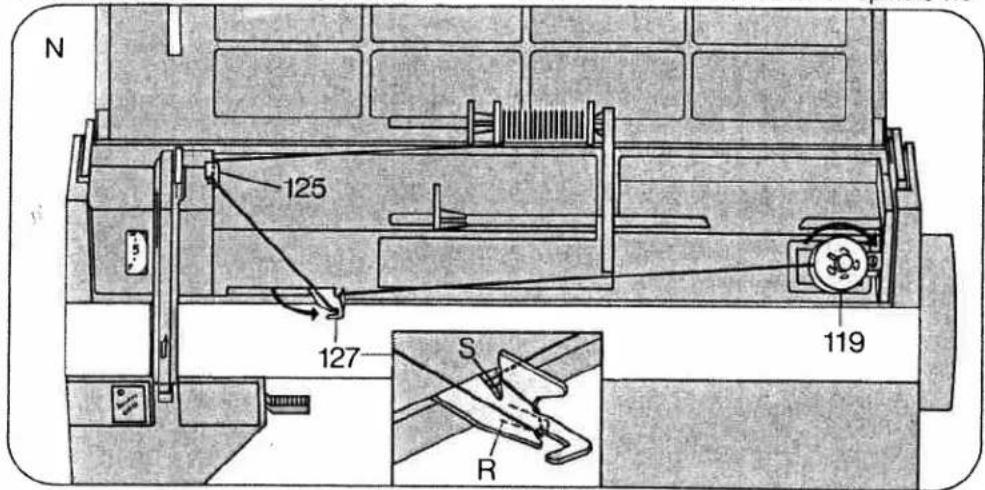
Illustration of hands operating a solar panel switch mechanism (no text or symbols visible)Winding the bobbin from a second spool (N)
Disengage the sewing mechanism (see page 5). Swing the second spool holder toward the back. Push a small spool of thread and a small unreeling disc on it. Place a bobbin on spindle 119 and turn it so that pin P enters slot Q (Fig. 0). Pull the thread from the spool, draw it through guide 125 and then into guide 127, as shown in the illustration, making sure the thread is positioned between the guide and tension spring R. From there pull the thread to the bobbin winder and wind it around the bobbin a few times. Push the bobbin winder toward the right, press
down the foot control pedal and wind the bobbin. The bobbin winder stops automatically when the bobbin is full. Push the full bobbin toward the left and take it out, cutting the thread in thread cutter S. Re-engage the sewing mechanism.
Important: On Model 1067 the bobbin winder must be disengaged for sewing. On Model 1069, you can wind the bobbin during sewing.
Load thread reel with diagonal cut for end of thread facing to right.
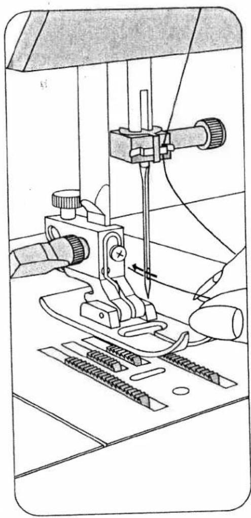
Winding through the needle eye (0) Raise the sewing foot. The needle must be in its 'up' position. Disengage the sewing mechanism. Place a bobbin on spindle 119
text_image
N 125 127 S R 119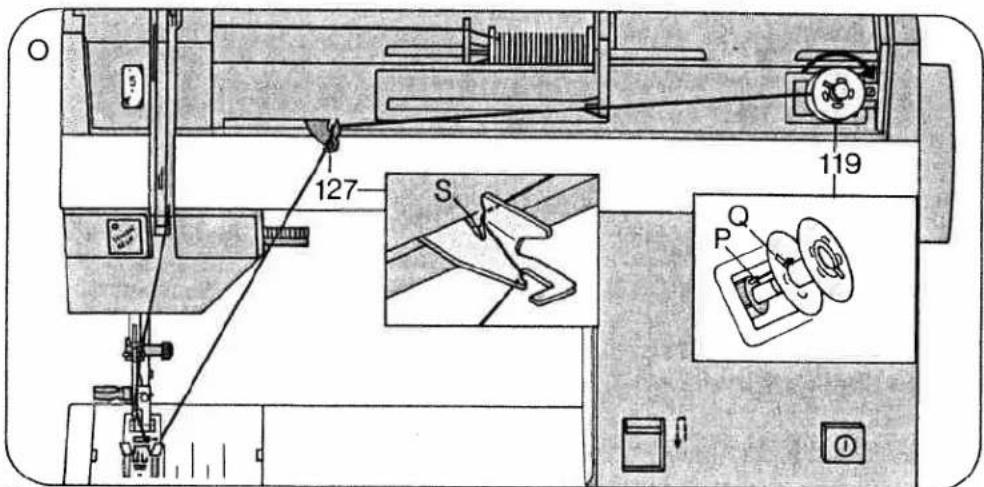
text_image
127 S 119 P Qand turn it so that pin P enters slot Q. Draw the needle thread under the sewing foot, up and into guide 127. From there pull the thread to the bobbin winder and wind it around the bobbin a few times. Push the bobbin toward the right, press down the foot control pedal and wind the bobbin. The bobbin winder stops automatically when the bobbin is full. Push the full bobbin toward the left and take it out, cutting the thread in thread cutter S. Re-engage the sewing mechanism.
Removing bobbin case and bobbin Open free arm cover 121. Pull out latch N, then lift out the bobbin case, release the latch and take out the bobbin. The bobbin cannot fall out as long as you keep latch N pulled out.
Inserting the bobbin
Insert the filled bobbin into the bobbin case so that the thread unreels toward the back (N). Then draw the thread into slot O and under the spring into eye P.

text_image
121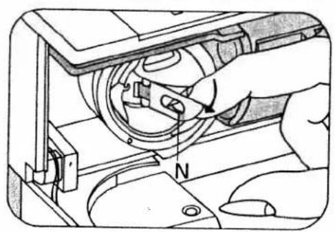
text_image
Technical diagram showing a hand operating a mechanical device with labeled component 'N'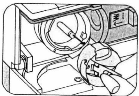
natural_image
Technical line drawing of a mechanical device with no visible text or symbols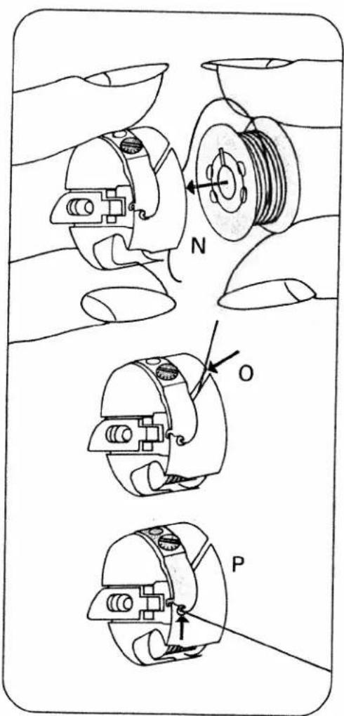
text_image
Technical diagram showing three mechanical assembly steps labeled N, O, and P with directional arrows indicating movement or force.Inserting the bobbin case
Pull up latch P and push the bobbin case onto stud O as far as it will go. Cutout N must point upwards. Release the latch. Stud O and latch P must be flush. Close the free arm cover. It must always be kept closed during sewing.
Drawing up the bobbin thread
Hold the needle thread a little taut. Turn hand wheel 102 toward you until the needle moves down and up again and the take-up lever is up. Pull the bobbin thread out of the needle hole and lay both threads toward the left and back under the sewing foot.
On model 1069 the bobbin thread can be drawn up by operating the basting stitch button. Press the button, depress the pedal and again press the button.

text_image
Technical diagram showing mechanical assembly with labeled parts N and P, including a compass needle indicating direction.8

natural_image
Line drawing of a sewing machine needle stitching on a workbench (no text or symbols)Presser bar lifter
Lever 114 has four positions:
N = The sewing foot is raised. (Before you remove the work, turn the hand wheel toward you to raise the needle and the take-up lever.)
O = The sewing foot is raised further for inserting extra-thick materials.
P = Darning position for darning foot only. Lower the presser bar lifter and at the same tane push it back slightly until it enters notch R at the bottom of its slot.
Q = The sewing foot is lowered for sewing.
Thread cutter
The thread cutter is an oblique slot located at the back of the presser bar. Raise the sewing foot. Pull the work out of the machine toward the back. Draw the threads into the cutter slot and pull them downwards to cut them.

text_image
N R 114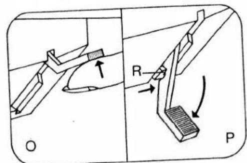
text_image
O R P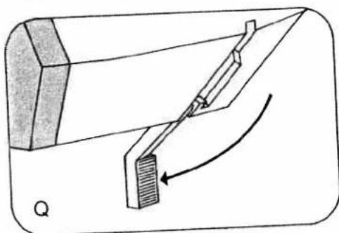
natural_image
Diagram of a mechanical device with a lever and curved arrow indicating motion (no text or symbols)
natural_image
Line drawing of a sewing machine needle and base mount (no text or symbols)Upper tension (124)
N = Setting mark. The normal tension setting is in the white range between 3 and 5. The higher the number, the tighter the tension.
Lower tension
O = Regulating screw. Turn it left for a looser tension, or right for a tighter tension. P = Both tensions are correct. Q = Upper tension too loose or lower tension too tight.
$$ \begin{array}{l} R = \text { Lower tension too loose or upper } \ \text { tension too tight. } \end{array} $$
The correct lower tension
Let the bobbin case with a full bobbin hang down freely by the thread. It must not slide down by its own weight, but should gradually move downwards when you jerk your hand upwards lightly. Once the lower tension has been set correctly, only the upper thread tension should be adjusted.

natural_image
Technical line drawing of a mechanical device with internal components and a compass indicating north (no text or symbols present)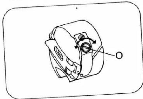
natural_image
Technical line drawing of a mechanical component with no visible text or symbols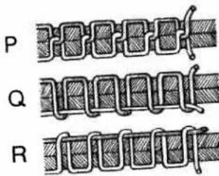
text_image
P Q R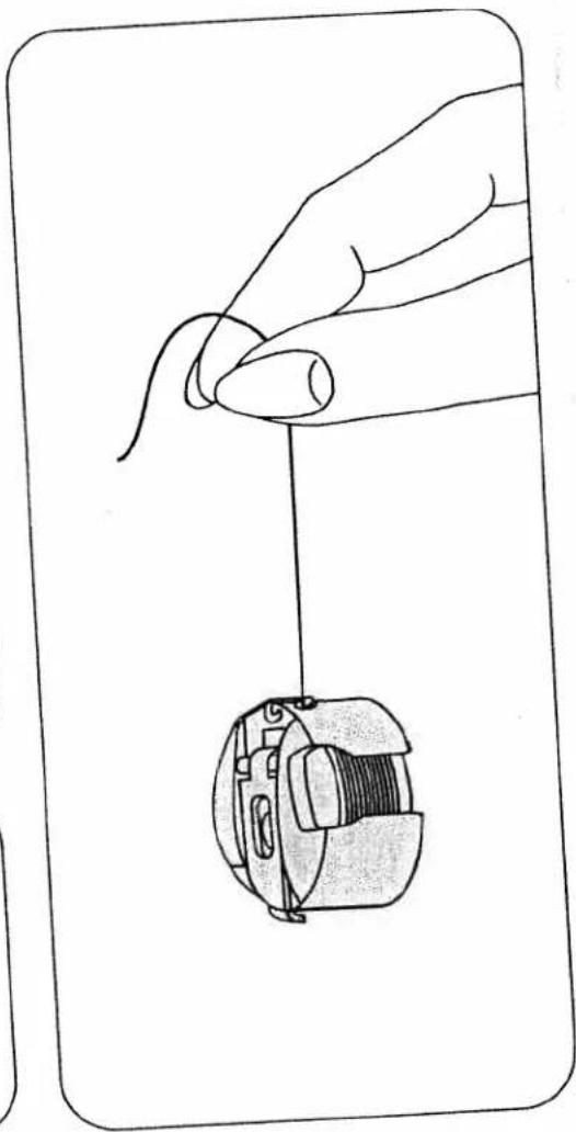
natural_image
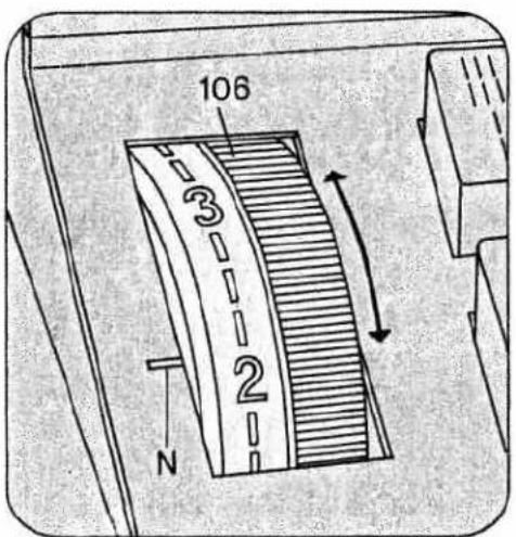
Line drawing of a hand holding a small mechanical component, no text or symbols presentRegulating the stitch length
The numbers on stitch length control 106 indicate the stitch length in millimeters.
The stitch length range is 0 to 6 mm. Turn the control so that the number indicating the stitch length desired is opposite mark N.
Fig. 0 shows how to set the stitch length control for sewing stretch stitches (red stitch symbols on push buttons).
Reverse sewing
Press button 117. As long as you keep this button depressed, the machine sews backwards.
text_image
106 3 2 N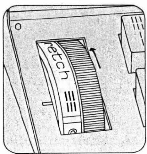
text_image
reetch ≡≡ e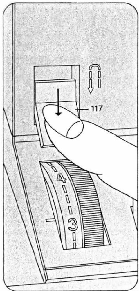
text_image
117 4 3Finger-tip controls
A, B, C: Buttons for buttonholing Button B is also used as clearing button for releasing the pushed buttons and for setting the left stitch length (see page 14).
D Elastic triple zigzag stitch, 2 mm 2-mm zigzag stitch
E Elastic triple zigzag stitch, 3.5 mm 3.5-mm zigzag stitch
F Elastic triple zigzag stitch, 5.0 mm
5-mm zigzag stitch
G Elastic triple straight stitch
Straight stitch
H Pullover stitch
Blindstitch
I Closed overlock stitch Joining stitch
K Overlock stitch Shell-edge stitch
L Feather stitch
Elastic decorative stitch
M Honeycomb stitch
Elastic stitch
A stitch program chart is found on the inside of the hinged top cover. This chart is also reproduced on pages 26 to 29 of this booklet and shows all stitches and stitch combinations together with their possible applications.

text_image
Diagram of a device panel with labeled components and directional arrows, showing various electrical or mechanical symbols.Selecting utility stitches
(white symbols)
Push the desired button and turn the stitch length control to the number indicating the desired stitch length between 1 and 6.
All zigzag, utility and stretch stitches are halved in width when button G is pressed too.
Selecting stretch stitches
(red symbols)
Push the desired button and turn the stitch length control as far as it will go (red symbol).
natural_image
Hand pressing a button on a mechanical component (no text or symbols visible)
natural_image
Hand placing a component into a mechanical or electrical component with no visible text or symbols
text_image
3 2
text_image
retch 三三Utility- and stretch-stitch combinations The various stitch combinations are shown in the chart on the inside of the hinged top cover and at the end of this booklet, together with sewing instructions. For example, if you want to sew an elastic blindstitch, push buttons M and F, select a stitch length between 1 and 4.
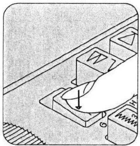
Selecting the needle position for straight stitching
Left needle position: push button B
Central needle position: push button G
Right needle position: push buttons H and I.

natural_image
Illustration of a hand pressing down on a computer mouse with magnetic field lines (no text or symbols)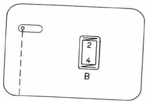
text_image
2 4 B
natural_image
Simple line drawing of a rectangular object with a vertical line and a labeled rectangle marked 'G' (no text or symbols beyond the label)
text_image
H + IDropping the machine feed
Open free arm cover 121. Push the drop-feed control toward N. The feed dog is dropped for embroidering, darning, bast-
ing etc. For sewing, push the drop-feed control toward O.
Always close the free arm cover again after making adjustment.
Changing the needle
Raise the needle bar. Then hold the needle, loosen screw N and pull the needle out downwards. Insert a new System 130/705 H needle (with the flat side of its shank facing toward the back) and push it up as far as it will go. Then tighten screw N.
Twin needles with a needle distance of 1.4 mm may be used for zigzag and utility-stitch sewing.

text_image
121
text_image
Technical diagram of a device with labeled ports and directional arrows indicating movement or flow
natural_image
Technical line drawing of a sewing machine with needle, screwdriver, and clasp mechanism (no text or symbols)Important
On Model 1067 the bobbin winder must always be disengaged for sewing.
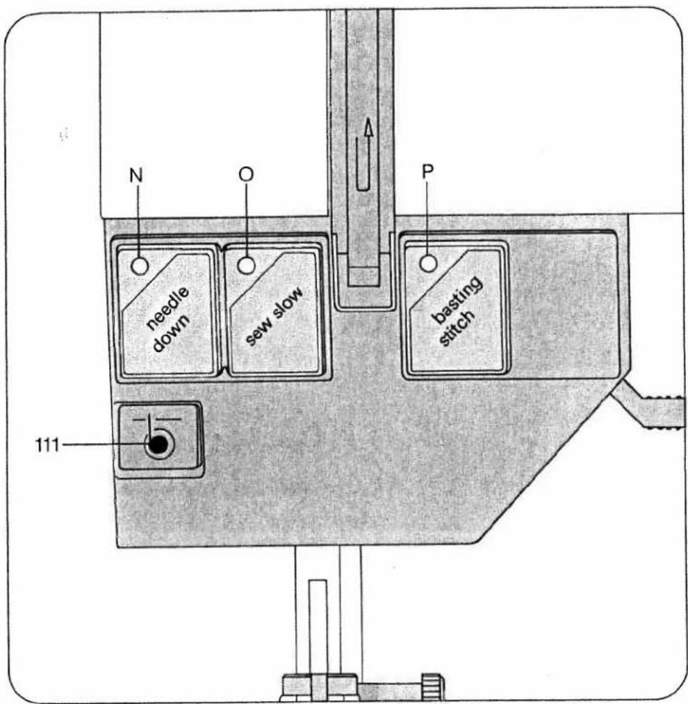
Operating controls of electronic system of Model 1069
"needle down" button with indicator light N
"sew slow" button with indicator light O
"basting stitch" button with indicator light P
Operating controls of electronic system of Model 1067
"sew slow" button with indicator light O.
text_image
N O P needle down sew slow basting stitch 111Basting (1069)
Press the basting stitch button. The green indicator lamp P lights up. Drop the machine feed (page 15) and screw on the darning foot (page 20). Place the fabric under the sewing foot. Each time you press and release the foot pedal the machine sews one stitch. Move the fabric under the sewing foot until the length of stitch required is obtained, then holding the fabric in this position, press down the foot pedal and release it again. Repeat this operation for each basting stitch.
When you have finished basting move your foot from the pedal and press basting stitch button again. The green indicator lamp P goes out. Push the drop-feed control to the left again. Close free arm cover 121.
Electronic top speed selection (1067 and 1069)
By pressing the "sew slow" button, the top speed of your machine can be halved. At the same time indicator light O lights up. When you press this button again, the indicator light goes off and the machine speed can be varied at will. The full piercing power of the needle remains the same at any speed.
Electronic bobbin thread monitor (1069)
The red signal lamp of bobbin thread monitor III starts to flash when the bobbin thread is running out. The lamp goes out when a full bobbin is inserted and sewing continues.
Important: Free arm cover 121 must be kept closed.
The Pfaff 1069 has a special bobbin (important when re-ordering).
Needle positions "up" and "down" (1069)
After sewing the needle is always retained at its "up" position. When you press the "needle down" button, indicator light N lights up and the needle remains down in the fabric (for sewing corners and turning the fabric) whenever sewing is interrupted. When you press the button again, the indicator light goes off, the needle moves upwards and is retained in its "up" position whenever the machine stops.
The button can be pressed during sewing.
Changing the sewing foot
To release the sewing foot push the red button N. When attaching a sewing foot make sure stud O enters slot P. Place the sewing foot under the sewing foot holder and hold it in place with your left hand.
Lower presser bar lifter 114 and at the same time reposition the sewing foot so that stud O fits in slot P. Hole R and screw Q are used for attaching an edge guide and the darning foot. Screw S serves to secure the sewing foot holder on the presser bar.

natural_image
Line drawing of a sewing machine needle and fabric being adjusted, showing the mechanism (no text or symbols)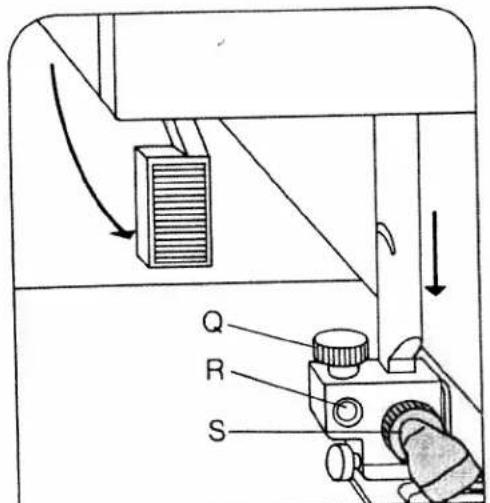
text_image
Q R S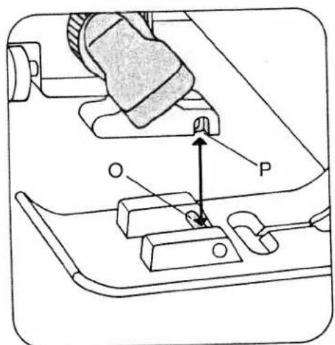
text_image
Technical diagram showing mechanical assembly with labeled parts O and P, including a highlighted component and directional arrow.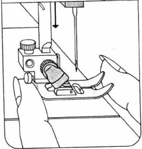
natural_image
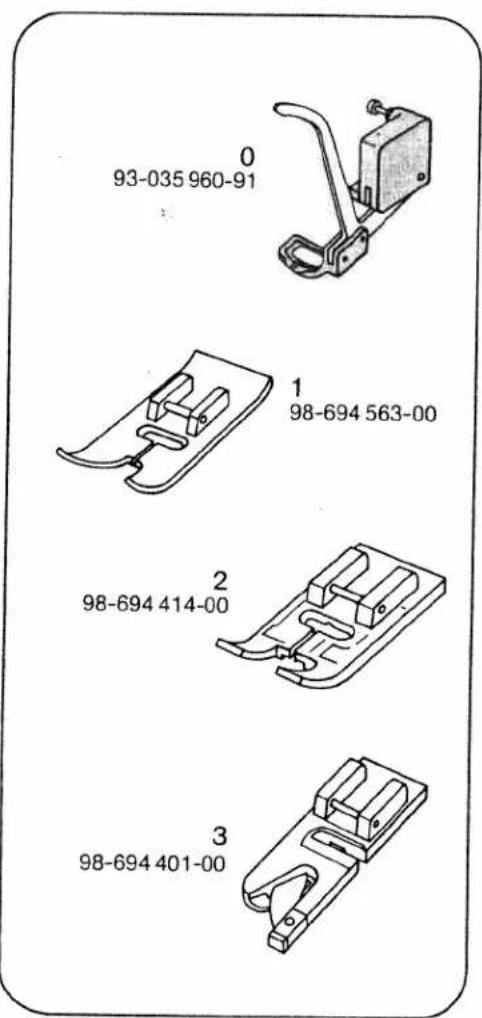
Line drawing of a sewing machine needle stitching fabric, with hands operating it (no text or symbols)Sewing feet
0 Darning foot
1 Standard sewing foot
2 Clear-view foot
3 Hemmer foot
4 Blindstitch foot
5 Zipper foot
6 Buttonhole foot
7 Edge guide
text_image
0 93-035 960-91 1 98-694 563-00 2 98-694 414-00 3 98-694 401-00
text_image
4 98-694 407-00 5 98-694 404-00 6 98-694 411-00 7 98-802 422-00Special sewing feet
N Blindstitch foot. Blindstitch guide R is adjusted by turning screw Q.
O Zipper foot. First insert its rear pin into groove S, then push its front pin into groove T. The zipper foot can be adjusted sideways for stitching along the right or left zipper chain.
P Darning foot. Raise the needle bar. Push bracket W toward the back and hold it there. Insert the pin of the foot in hole U and attach the foot so that it rests against its stop. Release bracket W so that it bears against screw X. Tighten screw V.
Buttonhole settings
Regulate the stitch density in the button-hole range of the stitch length control (Q). Press button C (N). Attach the buttonhole foot. Set the upper tension at 3 in the buttonhole range. Insert the filler cord as follows (C): Place it over the rear lug of the foot, pull it taut and clamp it in front lug D.
As you sew, arrow E moves along scale F. This serves to determine the buttonhole length.
Use a thin thread for sewing buttonholes.

text_image
Technical diagram of a mechanical assembly with labeled parts and directional arrows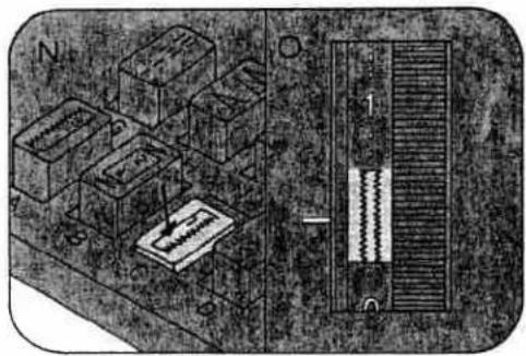
natural_image
Isometric view of a mechanical assembly with labeled components (N, O) and a central bar, no readable text or symbols present.
text_image
S T O
text_image
P Q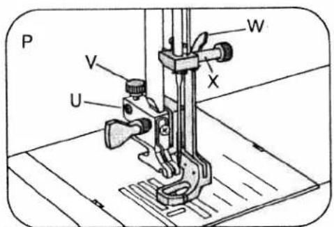
text_image
P V U W X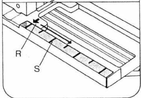
text_image
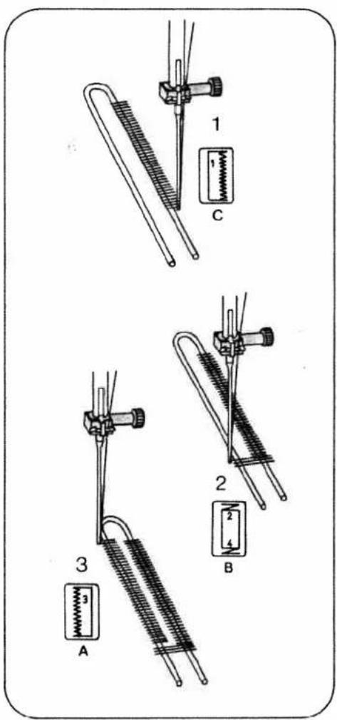
R SSewing buttonholes
Pull the bottom of the buttonhole foot forward as far as it will go.
1 Sew first buttonhole seam. Raise the needle (on Model 1067)
2 Push button B and keep it depressed until the machine has sewn 4 to 6 bar-tacking stitches. Raise the needle (on Model 1067). Then release the button.
3 Push button A. Sew the second buttonhole seam the same length as the first. Raise the needle (on Model 1067).
4 Push button B and keep it depressed until the machine has sewn 4 to 6 bar-tacking stitches. Raise the needle (on Model 1067). Then release the button.
5 Sew a few tying stitches. Remove the fabric, pull the filler cord taut and trim.
6 Cut the buttonhole open.
text_image
1 C 2 3 A B
text_image
4 2 4 B 5 6Changing the light bulb
Switch off the machine and pull out the power cord plug. Close the hinged top cover and swing up the carrying handle.
Take the edge guide out of the accessory box and insert it into the slot between face cover and housing and into cutout Q in the machine. Push the lamp housing down with the edge guide and hold it there. The light bulb can now be exchanged.
Push the light bulb up, turn it toward N and take it out. Insert the new bulb so that its pins slide in slots P. Push it up and turn it toward O. Let the lamp housing
resume its original position and pull out the edge guide.
Cleaning and oiling
Tilt needle plate 108 up at the back (N) and take it out (O). Clean the machine feed and the parts in the vicinity of the sewing hook with a soft brush. Clean the bobbin thread monitor of Model 1069 as instructed on page 25.
Do not oil the machine because it requires no maintenance. All you have to do is put a drop of oil in the hook raceway now and then, as shown in the illustration below.
natural_image
Illustration of a hand operating a sewing machine with a knob inserted (no text or symbols visible)
text_image
N O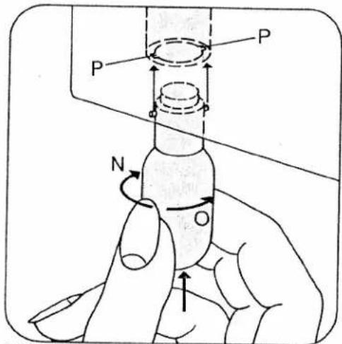
text_image
P P N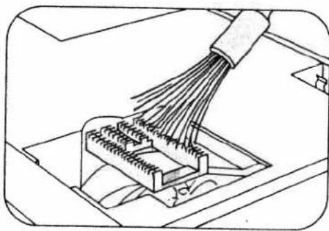
natural_image
Diagram of a connector with bundled wires and connectors, no text or symbols present
natural_image
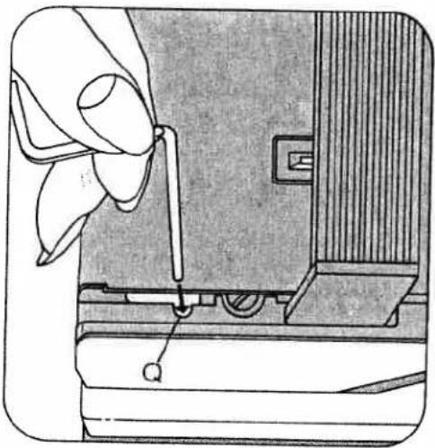
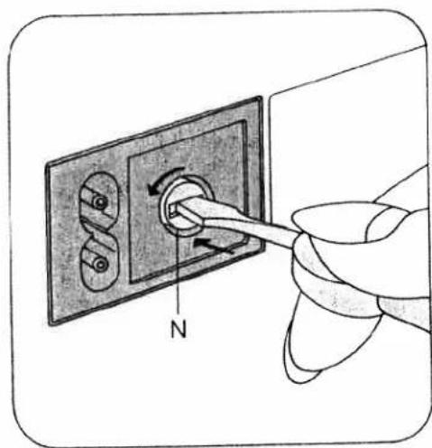
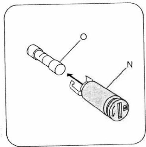
Technical line drawing of a mechanical component with a tool inserted, showing internal components and a circular housing (no text or symbols)Changing the fuse
Pull out the power cord plug. Turn fuse holder N counter-clockwise a quarter turn with a screwdriver, release it and take it out. Pull fuse O out of holder N. Insert a new fuse in the holder and replace the holder, pushing it in with the screwdriver and turning it clockwise a quarter turn. FF2A fuses can be obtained from your local Pfaff dealer.
natural_image
Hand inserting a cable into an electrical outlet with a compass needle (no text or symbols)Some safety rules
- Be careful when sewing that your fingers will not be injured by the needle.
- Make sure you pull out the power cord plug whenever you want to change fuse, needle, sewing foot, bobbin or needle plate, when you clean and oil the machine, or when you have to interrupt sewing and leave the machine for a while.
- Be sure to use only a 15-watt light bulb in the sewing lamp.
text_image
Diagram showing a device with labeled parts O and N, indicating a mechanical or electrical component.Trouble shooting
Cause:
Remedy:
1. Machine skips stitches
Needle not inserted correctly.
Push needle up as far as it will go, its flat shank side facing toward the back.
Wrong needle used.
Insert system 130/705 H needle.
Machine threaded improperly.
Check threading.
Needle too thin for thread used.
Select needle according to Needle and Thread Chart.
2. Needle thread breaks
For any of the above reasons.
See par. 1 above.
Thread tension too strong.
Regulate thread tensions.
Poor-quality or knotty thread used, or thread that has become too dry by excessive storage.
Used only good-quality thread.
3. Needle breaks
Needle not pushed up as far as it will go.
Insert new needle and push it up as far as it will go.
Needle bent.
Insert new needle.
Needle too thin or too thick.
See Needle and Thread Chart.
Needle bent and strikes needle plate because work is pushed or pulled.
Let machine feed the work alone.
Bobbin case improperly inserted.
Only guide the material lightly.
When inserting the bobbin case, push it in as for as it will go.
4. Seam is not uniform
Tension out of adjustment.
Check upper and lower tensions.
Thread too thick, knotty or hard.
Use first-class thread only.
Bobbin thread wound unevenly.
During bobbin winding, do not hold thread in hand, but pass it through the bobbin tension stud.
Kinks appear on top and bottom of material.
Thread machine properly and check both tensions.
Cause:
Remedy:
5. Machine feeds irregularly or not at all
Lint has accumulated between tooth rows of feed dog.
Remove needle plate and clean out lint.
Feed dog dropped. (Drop-feed control is at right.)
Flick drop-feed control to the left.
6. Machine runs with difficulty
Thread ends in hook raceway.
Remove thread ends and put a drop of oil into hook raceway.
7. Electronic bobbin thread monitor does not work (on Model 1069)
Thread ends and dirt have collected in the free arm cover over the indicator lamp, in the hook raceway, in the bobbin case, behind the hook and on the second indicator lamp to the right behind the hook.
Remove thread ends and dirt. Special care should be taken in the area round the second indicator lamp.
8. The machine only sews slowly, the needle has no piercing power and the electronic system is not working (on Model 1067)
The bobbin winder is engaged; it is at the right.
Push the winder to the left (to disengage it).
9. The machine sews only one stitch (on Model 1069)
The machine is set for basting.
Take the foot from the foot control and press the basting stitch button; the indicator lamp goes out.
10. The sewing lamp lights up, but the machine is not running Fuse is faulty
Fuse is faulty.
Insert new fuse.
11. Fundamental rules
Never run a threaded machine unless there is a piece of fabric under the sewing foot. If you have to leave the machine, even for a short while, be sure to switch off the master switch. This is particularly important when children are around.
Stitch program chart
Listed in this chart are the stitch program number, the corresponding stitch and, in the lower half, the buttons to be pressed
to sew this seam pattern. For all stitch programs marked "stretch", turn the stitch length control toward "stretch" as far as it
| 01 | 02 | ||||
| G | H | D | DE | E |
| 03 | 04 | 05 | 06 | |||
| A | B | C | stretch | G | stretch | M |
| No. | Stitch | Application |
| 01 | Straight stitch | All ordinary sewing operations and 6-mm fancy stitching operations. |
| 02 | Zigzag stitch | Edge finishing, appliqué work, inserting lace, button sewing, satin stitching, embroidering, darning etc. |
| 03 | Buttonholes | Just push the buttons and the buttonhole is finished. The stitch density can be regulated. |
| 04 | Elastic triple straight stitch | Seams exposed to great stress which stretch under stress. |
| 05 | Elastic triple zigzag stitch | Flat, elastic reinforcing seams, as well as sewing and mending corsetry. |
| 06 | Elastic stitch | Inserting patches and darning rips on elastic fabrics. |
| 07 | Elastic ornamental stitch | Inserting patches and darning rips on elastic materials or sewing ornamental seams on elastic fabrics. |
| 08 | Crown stitch | An ornamental seam, e.g. on night gowns. |
| 09 | Elastic blindstitch | Hemming elastic fabrics with invisible stitches. |
| 10 | Scallop stitch | For decorating handkerchiefs, for instance. |
will go. For all other programs, select the stitch length as desired. The individual stitch programs and their application are
described in more detail in the table below.
| 07 | 08 | 09 | 10 | 11 | 12 | 13 |
| L | ME | MF | MG | M stretch | MD stretch | ME stretch |
| 14 | 15 | 16 | 17 | 18 | 19 | 20 |
| M stretch F | M stretch G | I | I D | I F | I G | K |
| No. | Stitch | Application |
| 11 | Honeycomb stitch | Sewing on elastic threads or covering seams on terry cloth. |
| 12 | Joint stitch | A durable ornamental joining seam. |
| 13 | Florentine stitch, narrow | For decorating hems, e.g. on bed linen. |
| 14 | Florentine stitch, wide | Ornamental seams, e.g. on bed linen. |
| 15 | Houndstooth stitch | Ornamental seams, e.g. on table linen. |
| 16 | Lampshade stitch, wide | Classical ornamental seam on all plain fabrics. |
| 17 | Viennese stitch, narrow | Ornamental seams, e.g. on napkins. |
| 18 | Viennese stitch, wide | Ornamental seams, e.g. on table cloths. |
| 19 | Lampshade stitch, narrow | Classical ornamental seam on plain fabrics. |
| 20 | Shell-edge stitch, wide | Effective edge finish on dainty fabrics. |
| 21 | 22 | 23 | 24 | 25 | 26 | 27 |
| K | K | I stretch | I stretch | I stretch | I stretch | K stretch |
| D | G | F | D |
| 28 | 29 | 30 | 31 | 32 | 33 | 34 | ||||||
| K stretch D | K stretch G | K stretch M | H | H D | L C | L D |
| No. | Stitch | Application |
| 21 | Elastic edge stitch | Finishing edges that do not fray much. |
| 22 | Shell-edge stitch narrow | Ornamental seams, e.g. on girls' dresses. |
| 23 | Closed overlock stitch, wide | Covering folded fabric edges with a fancy seam. |
| 24 | Pennant stitch | Decorative joining seam and sewing on borders. |
| 25 | Closed overlock stitch, narrow | Sewing on dainty lace. |
| 26 | Turkish stitch | Topstitching patches. |
| 27 | Overlock stitch, wide | Elastic assembly and edge finishing seams on knitted fabrics. |
| 28 | Peacock stitch | Festive ornamental seam, e.g. on table linen. |
| 29 | Overlock stitch, narrow | Dainty border ornamentation. |
| 30 | Knurl stitch | Ornamental seam on light clothing. |
| 31 | Blindstitch, wide | Hemming heavier fabrics with invisible stitches. |
| 32 | Blindstitch, narrow | Hemming lightweight fabrics with invisible stitches. |
| 33 | Peak stitch | A dainty ornamental seam, e.g. on ladies' handkerchiefs. |
| 34 | Mound stitch | Ornamental seam, e.g. on children's napkins. |
| 35 | 36 | 37 | 38 | 39 | 40 | 41 |
| L F | L I | H stretch | H D stretch | H G stretch | L stretch | L D stretch |
| 42### | stretch | stretch | stretch | stretch | stretch | stretch | stretch |
| 43### | stretch | stretch | stretch | stretch | stretch | stretch | stretch |
| 44### | stretch | stretch | stretch | stretch | stretch | stretch | stretch |
| 45### | stretch | stretch | stretch | stretch | stretch | stretch | stretch |
| No. | Stitch | Application |
| 35 | Viennese stitch, narrow | Ornamental seams, e.g. on table linen. |
| 36 | Lampshade stitch, narrow | Classical ornamental seam on plain fabrics. |
| 37 | Pullover stitch, wide | Elastic edge finishing seams on jersey fabrics. |
| 38 | Pullover stitch, medium | Elastic edge finishing seams on polo shirt farbrics. |
| 39 | Pullover stitch, narrow | Elastic edge finishing seams on lightweight jersey crepe. |
| 40 | Feather stitch | Decorative cover seams, e.g. on aprons. |
| 41 | Dutch stitch | Ornamental seam, e.g. on kitchen textiles. |
| 42 | Snail stitch | Ornamental seam, e.g. for bath room utensils. |
| 43 | Loom stitch | Ornamental seam, e.g. for country-look dresses. |
| 44 | Diagonal stitch | Ornamental seam, e.g. for plain-look, modern dresses. |
| 45 | Trellis stitch | Ornamental seam, e.g. for airy ladies' dresses. |
| 46 | Twig stitch | Ornamental seam, e.g. for hiking wear. |
| 47 | Border stitch | Ornamental seam, e.g. for border ornamentations on pockets. |
| 48 | Triangular stitch | Ornamental seam, e.g. for children's night dresses. |
Special accessories
The special accessories listed below are intended for special sewing jobs. They can be obtained from your dealer.
| Accessory | Part. No. | Sewing Operation |
| Appliqué foot | 93-035 920-91 | For appliqué work |
| Cording setconsisting of: | For cording work(Needle size 80,for fine cordingneedle size 70) | |
| Cording foot, 5 grooves(twin needle with 1.8-2.5 mm needle gauge) | 93-035 950-91 | |
| Cording foot, 7 grooves(twin needle with 1.4-1.8 mm needle gauge) | 93-035 953-91 | |
| Cording blade (2 ea.) | 93-035 952-45 | |
| Fringe sewing foot | 93-035 943-91 | For sewing fringes and for basting |
| Straight-stitch foot | 98-694 803-00 | For topstitching andsewing very delicateand soft fabrics (silk jersey, etc.) |
| Felling foot, 4.5 mm | For felled seams | |
| Felling foot, 6.5 mm | ||
| Shirring foot | 93-035 998-91 | For shirring valances |
| Single-needle cording foot | 93-035 915-91 | For single-needle cording |
| Eyeletting plate | 93-035 946-45 | For eyeletting |
| Overlock foot | 98-620 404-00 | For finsishing raw edges or for joiningelastic fabrics and simultaneonslyovercasting their edges |
| Hemmer foot (rolled edge), 2 mm | 98-694 804-00 | For hemming edges with zigzag stitches |
| Teflon foot | 98-694 801-00 | For sewing plastic materials |
PFAFF-HANDELSGESELLSCHAFT
Printed in West Germany
Subject to alterations in design.