synchromatic 1215 - Sewing machine PFAFF - Free user manual and instructions
Find the device manual for free synchromatic 1215 PFAFF in PDF.

User questions about synchromatic 1215 PFAFF
0 question about this device. Answer the ones you know or ask your own.
Ask a new question about this device
Download the instructions for your Sewing machine in PDF format for free! Find your manual synchromatic 1215 - PFAFF and take your electronic device back in hand. On this page are published all the documents necessary for the use of your device. synchromatic 1215 by PFAFF.
USER MANUAL synchromatic 1215 PFAFF
PFAFF synchromatic 1215 Instruction Book
natural_image
Close-up of a circular device with internal components and a close-up of its internal components (no visible text or symbols)
natural_image
Black-and-white photo of a PFAF sewing machine with front and side views (no visible text or symbols)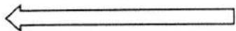
Fold out this page
Index
Page
Accessories drawer 2
Bobbin 4,5
Bobbin case 4,6
Bobbin thread 7
Buttonholing....20,21
Carrying case cover.... 1
Carrying handle.... 1
Cleaning 23
Dual feed....11
Electrical connection.... 3
Foot control 3
Foot control receptacle 1
Light bulb 23
Machine feed 9
Master selector dial.... 8
Needle....12
Needle position....9
Oiling....23
Overlock seam....18, 19
Presser bar lifter....11
Reverse sewing....9
Sewing feet 13, 16
Sewing mechanism.... 4
Slot-threading 6
Special accessories 26
Special sewing feet 17
Stitch program chart 27-29
Straight stitch 8
Thread cutter 12
Thread tensions....10
Trouble shooting....24, 25
Upper threading 7
Utility-stitch combinations 15
Utility stitches 14
Winding 5
Work support....22
Zigzag stitch....8
text_image
1 2 3 4 5 6 7 25 19 18 20 21 22 23 24 17 16 15 14 13 8 9 10 11 12Some safety rules
a) Be careful when sewing that your fingers will not be injured by the needle.
b) Make sure you pull out the power cord plug whenever you want to change needle, sewing foot, bobbin or needle
plate, when you clean and oil the machine, or when you have to interrupt sewing and leave the machine for a while.
c) Be sure to use only a 15-watt light bulb in the sewing lamp.
Parts of your sewing machine
1 Take-up lever
2 Thread retainer stud
3 Eraser button
4 Utility-stitch buttons
5 Spool pins
6 Bobbin winder
7 Balance wheel
8 Stop motion knob
9 Master selector dial
10 Needle position and buttonhole knob
11 Master switch
12 Accessories drawer
13 Free arm
14 Free arm cover (enclosing sewing hook)
15 Sewing foot
16 Sewing foot holder
17 Needle threader
18 Needle threader control
19 Upper tension
20 Control for reverse sewing and dropping the feed dog
21 Presser bar lifter (on back of machine arm)
22 Top feeding foot with thread cutter
23 Needle holder with needle set screw
24 Needle plate with guide grooves
25 Handle
IMPORTANT!
Valid for United Kingdom only!
The wires in this mains lead are coloured in accordance with the following code: Blue: Neutral, Brown: Live. As the colours of the wires in the mains lead of this appliance may not correspond with the coloured markings identifying the terminals in your plug, proceed as follows: The wire which is coloured blue must be connected to the terminal which is marked with the letter N or coloured black. The wire which is coloured brown must be connected to the terminal which is marked with the letter L or coloured red.
Please note:
When a 13-ampere plug is used a 3-ampere fuse has been fitted.
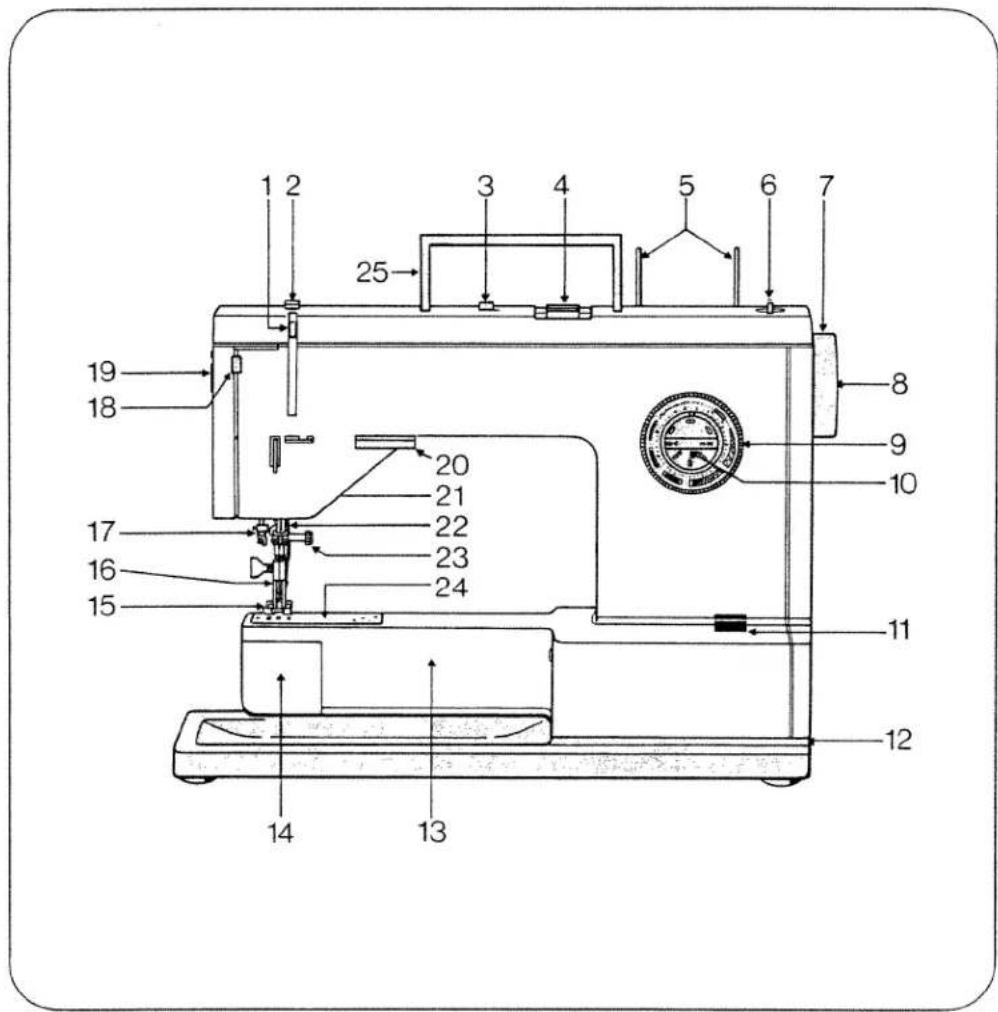
Removing the carrying case cover Lift the cover off.
Foot control receptacle
Remove this receptacle from the machine. Before you put the machine away after sewing, replace the receptacle in its original position (A).
Handle
The handle can be folded down, as shown by the arrow in ill. B.
natural_image
Technical line drawing of a mechanical device with two upward arrows indicating motion or assembly (no text or symbols present)
text_image
A BAccessories drawer
The accessories are kept in a drawer. Push the catch upwards a little (A) and at the same time pull drawer 12 out of the machine (B).
III. C shows how the accessories are to be placed in the drawer.

text_image
A 12
natural_image
Diagram of a refrigerator interior showing drawer, door, and seat (no text or symbols)C

natural_image
Technical line drawing of a mechanical assembly with tool, gears, and housing (no text or labels)Electrical connection
Push plug A into the machine socket and plug B into the wall socket. Press master switch 11. Your machine is now switched on and ready for sewing.
Foot control
Place the foot control under the table. Press down its pedal. The machine starts sewing. The more the pedal is depressed, the faster the machine will run.

text_image
11 A B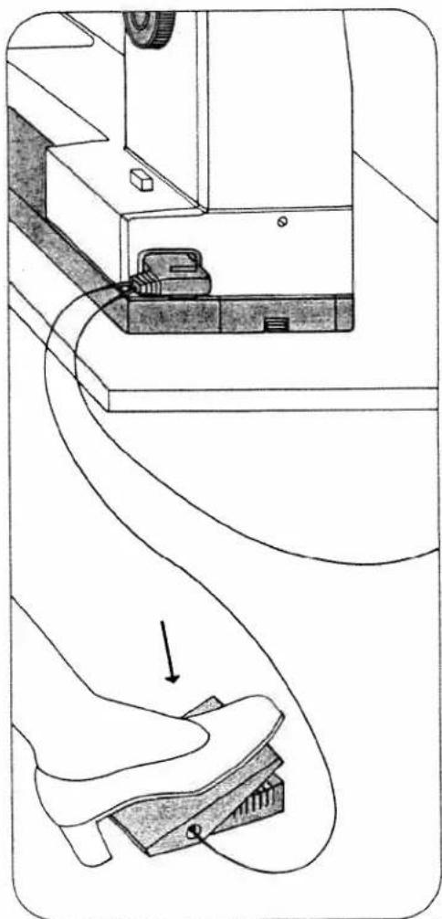
natural_image
Technical diagram showing a mechanical assembly with a curved component and a separate view of a mechanical part (no text or symbols present)Removing bobbin case and bobbin
Open free arm cover 14. Lift latch A, pull out the bobbin case, release the latch and take out the bobbin. The bobbin cannot fall out as long as you keep latch A raised.
Disengaging the sewing mechanism
Before you start winding the bobbin, disengage the sewing mechanism. To do this, hold the balance wheel steady and turn the stop motion knob toward you. After bobbin winding turn the knob in the opposite direction to re-engage the sewing mechanism again.

natural_image
Illustration of a hand holding a device with a scroll wheel, showing a 14-step assembly (no text or symbols present)
text_image
Technical diagram showing a hand operating a mechanical device with labeled component 'A'
natural_image
Illustration of a hand using a tool to adjust or install a mechanical component (no text or symbols visible)
natural_image
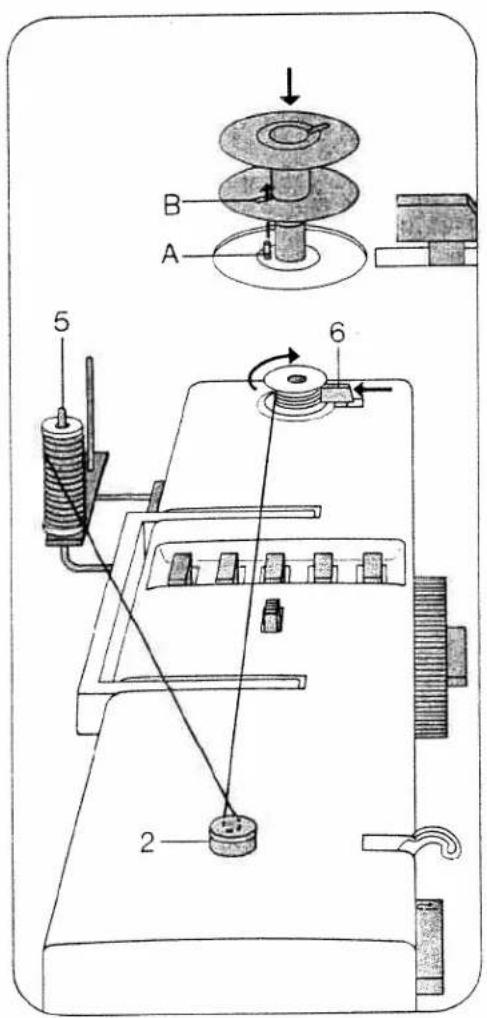
Illustration of hands operating a mechanical component with a dial indicator (no text or symbols present)Bobbin winding
Disengage the sewing mechanism. Raise pins 5. Place a bobbin on the bobbin winder so that pin A enters slot B. Place a spool of thread on one of the spool pins. Pass the thread around thread retainer stud 2 and wind it around the bobbin a few times, as indicated by the arrow. Push lever 6 against the bobbin to start the bobbin winder and hold the thread end at the beginning.
The bobbin winder stops when the bobbin is full. Re-engage the sewing mechanism.
If you want to stop the bobbin winder earlier, pull lever 6 forwards. Remove the bobbin and cut the thread.
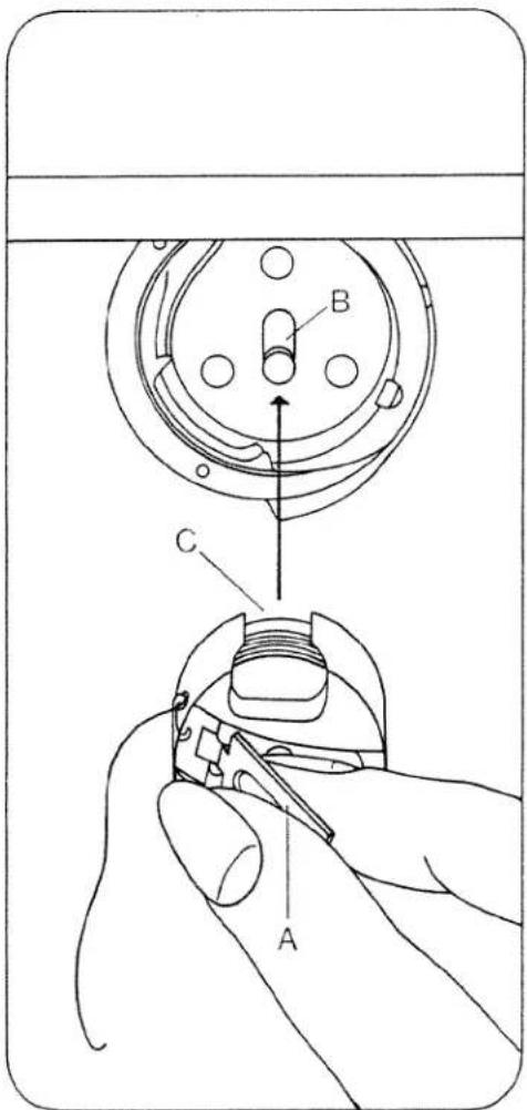
Inserting the bobbin
Insert the filled bobbin into the bobbin case so that the thread unreels toward the back (A). Then draw the thread into slot B and under the spring into eye C.
text_image
Technical diagram of a sewing machine with labeled parts and mechanical components
text_image
Technical diagram showing three mechanical assembly steps labeled A, B, and C with arrows indicating motion or movement.Inserting the bobbin case
Lift latch A and push the bobbin case onto stud B as far as it will go, making sure slot C points upwards. Release latch A. Latch A and stud B must be flush.
Upper threading
Pull the thread from the spool and draw it into slot A, guide B and take-up lever 1. Then pull it into guide C and thread guide D on the needle holder.
text_image
Technical diagram showing a hand operating a device with labeled parts A, B, and C for assembly or maintenance.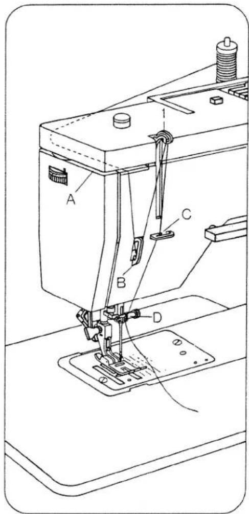
text_image
Technical diagram of a sewing machine with labeled parts A, B, C, and DThreading the needle
Turn the balance wheel toward you to raise the needle and take-up lever 1. Push needle threader control 18 down all the way. Draw the thread under fingers A and B, at the same time releasing control 18 and the thread. As you do this, the thread is pulled through the needle eye. Place the needle thread under hook A of needle threader 17. Push needle threader control 18 down as far as it will go. Then place the needle thread under hook B of the needle threader. At the same time release control 18 and the thread. The thread is now pulled through the needle
eye in a loop. Then pull the thread through the needle eye completely.
Drawing up the bobbin thread
Hold the needle thread a little taut. Turn balance wheel 8 toward you until the needle moves down and up again and the take-up lever is up. Pull the bobbin thread out of the needle hole and lay both threads toward the left back under the sewing foot.

text_image
1 18 17 A
natural_image
Technical line drawing of a sewing machine with needle and base mount (no text or symbols)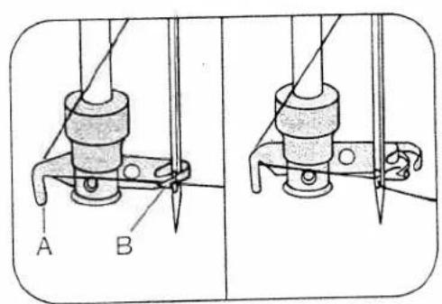
text_image
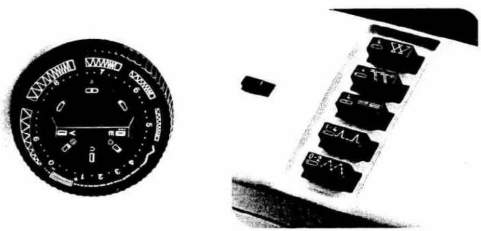
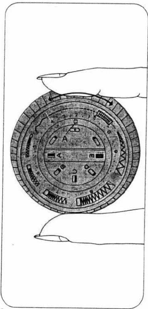
A BMaster selector dial (9)
Turn the outer ring until the symbol of the straight or zigzag stitch desired is positioned above mark A.
Straight stitch
Straight stitches are located in the range from 0 to 4.
Zigzag stitch
Setting mark = A
Zigzag stitches are sewn in the ranges marked 5, 6, 7, 8 and 9. At the right of this range the stitches are close together; toward the left, the zigzag stitches become increasingly longer. In ranges 4 and 5 a long, narrow zigzag stitch is made.
natural_image
Illustration of a hand holding a circular mechanical device with internal components (no text or symbols visible)
natural_image
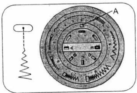
Circular diagram with concentric rings and central markings, no readable text or symbolsNeedle position
The needle can be set to different positions in the needle hole.
Turn knob 11 until the symbol of the needle position desired is positioned below mark A.
- = Central (normal) needle position
◦ = Right needle position
◦ = Left needle position
Reverse sewing and dropping the feed dog
Reverse-feed control 20 has the following positions:
A = Normal position
B = As long as the control is pressed, the machine sews backwards (for backtacking the end of a seam).
C = Vertical position. The machine sews permanently in reverse.
D = The feed dog is dropped (for embroidering, darning, etc.).
text_image
Technical diagram of a mechanical device with labeled components and a spring scale indicator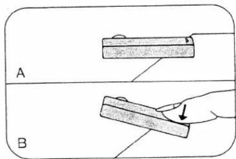
text_image
A B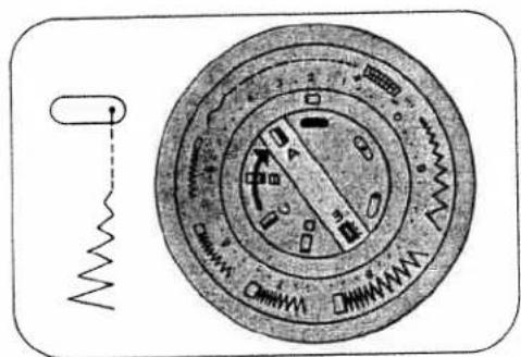
text_image
Technical diagram of a mechanical component with labeled parts and a spring symbol indicating a spring.
natural_image
Simple line drawing of a vertical cylindrical object with an arrow indicating rotation, no text or symbols present.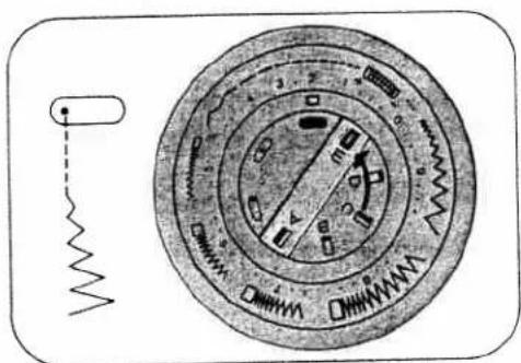
text_image
Technical diagram of a mechanical device with labeled parts and a spring scale indicator
flowchart
graph TD
    A["开始"] --> B{处理}
    B -->|是| C["结束"]
    B -->|否| D["返回"]
    D --> E["结束"]
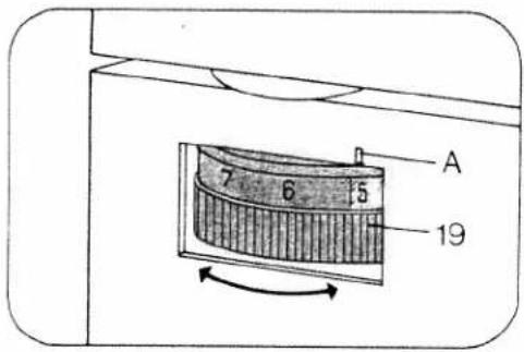
Upper tension
A = Setting mark. The normal tension setting is in the light-coloured range between 3 an 5, depending on the work. The higher the number, the tighter the tension.
Lower tension
B = Regulating screw. Turn it left for a looser tension, or right for a tighter tension.
C = Correct thread tension.
D = Upper tension too loose or lower tension too tight.
text_image
A 7 6 5 19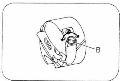
natural_image
Technical line drawing of a mechanical component with labeled part B (no text or symbols beyond label)
text_image
C D EE = Lower tension too loose or upper tension too tight.
The correct lower tension
Let the bobbin case with a full bobbin hang down freely by the thread. It must not slide down by its down weight, but should gradually move downwards when you jerk your hand upwards lightly. Once the lower tension has been set correctly, adjust the upper tension only.

natural_image
Line drawing of a hand holding a small mechanical component with a string, no text or symbols presentPresser bar lifter
Lever 21 has two positions:
A = Sewing foot is raised. (Before you remove the work, turn the balance wheel toward you to raise the needle and take-up lever 1.)
B = The sewing foot is lowered for sewing.
Dual feed
(Synchronized top and bottom feed) This feed mechanism prevents one ply from creeping ahead of the other. Before you engage or disengage the dual feed, raise the sewing foot.
To engage: Push top feeding foot 22 down until it snaps into place.
To disengage: Push the top feeding foot down slightly, then pull it back and let it swing up.

natural_image
Technical line drawing of a mechanical device with labeled component A (no text or symbols beyond label)
natural_image
Technical line drawing of a sewing machine with a climp and base mount (no text or symbols)
natural_image
Technical line drawing of a mechanical assembly with labeled component B (no text or symbols beyond label)
natural_image
Technical line drawing of a sewing machine with no visible text or symbolsChanging the needle
Raise the needle bar. Then hold the needle, loosen screw A and pull the needle out of the needle holder. Insert a new System 130/705 H needle (with the flat side of its shank facing toward the back) and push it up into the needle holder as far as it will go. Tighten screw A.
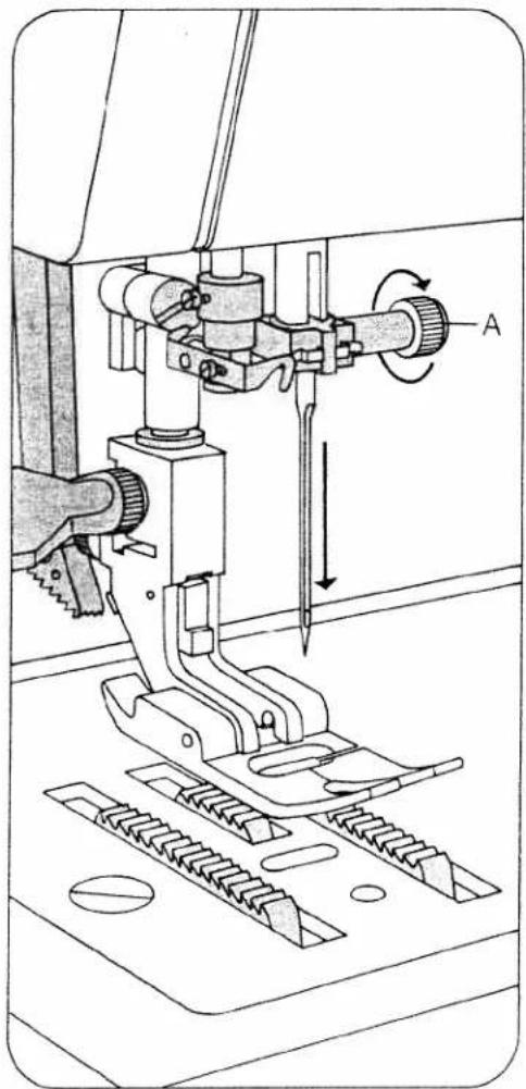
Thread cutter
The thread cutter is located at the back of top feeding foot 22. Remove the work by pulling it backwards out of the machine. Place the threads in thread cutter slot A and pull them downwards to cut them.
natural_image
Technical line drawing of a sewing machine with labeled component A (no text or symbols beyond label)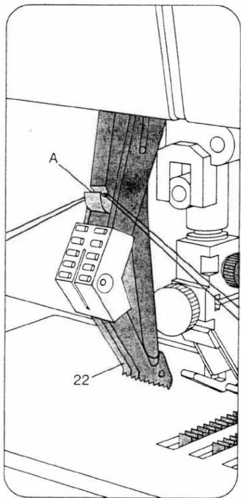
text_image
A 22Changing the sewing foot
To release the sewing foot push the red button A. When attaching a sewing foot make sure studs B enter slots C. Place the sewing foot under the sewing foot holder and hold it in place with your left hand. Lower the presser bar lifter and at the same time reposition the sewing foot so that studs B fit in slots C. If the sewing foot does not readily snap in place, press against screw D lightly.
Slot E and screw F are used for attaching an edge guide.

natural_image
Technical illustration of a sewing machine needle stitching a garment, showing cutting process and component alignment (no text or symbols)
natural_image
Technical line drawing of a sewing machine with no visible text or symbols
text_image
Technical diagram of a sewing machine with labeled parts A, B, and C, showing mechanical components and tool path.