hobbylock 795 - Sewing machine PFAFF - Free user manual and instructions
Find the device manual for free hobbylock 795 PFAFF in PDF.

User questions about hobbylock 795 PFAFF
0 question about this device. Answer the ones you know or ask your own.
Ask a new question about this device
Download the instructions for your Sewing machine in PDF format for free! Find your manual hobbylock 795 - PFAFF and take your electronic device back in hand. On this page are published all the documents necessary for the use of your device. hobbylock 795 by PFAFF.
USER MANUAL hobbylock 795 PFAFF
natural_image
Black-and-white illustration of a vintage sewing machine with no visible text or symbols on its bodyNotes on safety
A) Due to the up and down movement of the needle, the user must take sufficient care to avoid injury and observe the sewing area continuously while sewing.
B) When leaving the machine, changing parts or accessories, the machine must be disconnected from the power source.
C) The maximum approved wattage of the light bulb is 15 watts.
D) The drive belt must never be adjusted by anyone but an authorized Pfaff agent.
Contents
The controls of the sewing machine 2,3
Accessory box 4
Electrical connection 4,5
Foot control 5
Preparing for threading 6,7
Threading, 4-thread safety-stitch seam 7-11
Threading chainstitch looper 8
Threading overedge looper 9
Threading the needles 10
Inserting the lint box 11
Sewing test 12
Points to observe during sewing 13
Securing the seam 14
Checking and adjusting thread tension 15, 16
4-thread safety-stitch seam 17
2-thread chainstitch seam 17
2-thread overedge seam 17
Adjustment of the machine for two-thread chainstitch seam 18, 19
Thread chart 20
Adjusting the stitch length 21
Regulating the sewing foot pressure 21
Adjusting the seam width 22
Machine care 21
Changing the needles 23
Changing the lower knife 23, 24
Changing the upper knife 25
Changing the light bulb 26
Oiling the machine 27
Accessories 28
Specifications 28
Sewing problems and solutions 28, 29
Changing the sewing feet 30

text_image
2 1 3 4 5 6 7 21 20 19 18 17 16 15 8 9 10 11 12 13 14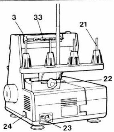
text_image
3 33 21 22 24 23
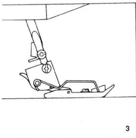
natural_image
Technical drawing of a mechanical component with a numbered label (25) pointing to a feature, no readable text or symbols present.Controls of the sewing machine
1 Foot pressure regulating dial
2 Thread guide
3 Carrying handle
4 Left needle thread tension dial
5 Right needle thread tension dial
6 Right looper thread tension dial
7 Left looper thread tension dial
8 Thread tension cover
9 Upper knife
10 Knife guard
11 Presser foot lifter lever
12 Hand wheel
13 Looper cover
14 Looper cover lever
15 Work support
16 Stitch length setting dial
17 Needle plate
18 Presser foot
19 Needle bar
20 Thread reel stand
21 Thread reel pins
22 Adjusting knob
23 Machine plug socket
24 Master switch
25 Lint box
26 Foot control
27 Foot control plug
28 Mains plug
29 Lower knife
30 Knife clamp screw
31 Right looper
32 Left looper
33 Thread guide bar

text_image
28 26 27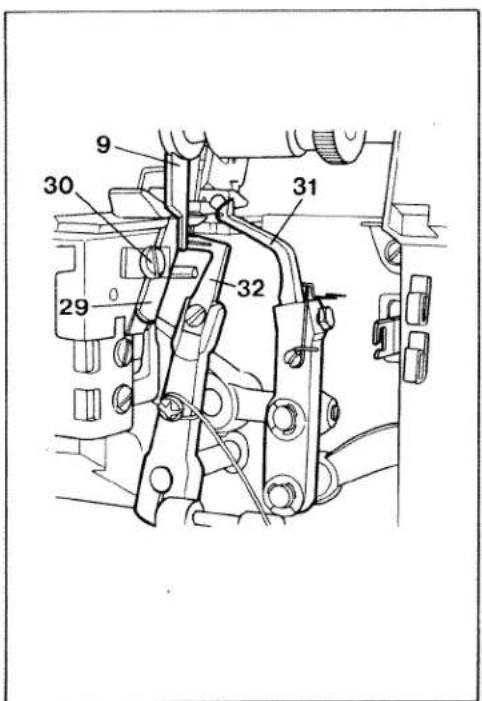
text_image
9 30 31 29 32
natural_image
Hand operating a mechanical device with a knob and lever mechanism (no text or symbols visible)Accessory box
Swing the work support to the left and pull out the accessory box.

natural_image
Technical line drawing of a mechanical assembly with a circular component and rod (no text or symbols)To replace the accessory box, slide it into the grooves and push it until it locks. The accessories are illustrated on page 28.
natural_image
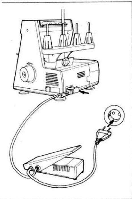
Line drawing of a sewing machine with attached electrical connector (no text or symbols)Electrical connection
Use this machine only on a flat surface or on a special sewing table.
Attaching the foot control: Insert the plug of the control into the machine plug socket. Then connect the mains plug to a power source.
Caution: When the machine is not in use, disconnect plug from power source. Do not place any objects on the foot control.
text_image
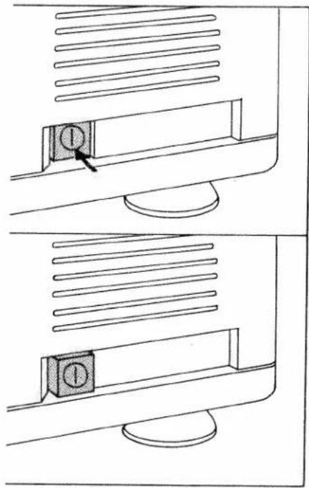
Diagram showing two views of a computer monitor with a labeled button, illustrating the screen's position and status.Switching the machine ON and OFF
Power and sewing light are switched on and off simultaneously with the master switch.
Switching on:
Press switch. Machine and sewing light are switched on.
Switching off:
Press switch again. Machine and sewing light are switched off.

natural_image
Diagram of a medical or anatomical device with an arrow pointing to a specific area (no text or symbols present)Foot control
The speed of the Hobbylock is regulated as follows:
When pressing the foot control gently, the machine will run at low speed; when pressing harder, it will run faster.
natural_image
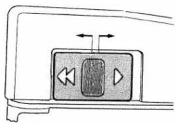
Diagram of a device control panel with playback buttons and directional arrows (no text or symbols)Electronic foot control
Maximum speed is adjusted in two grades by the switch on the foot control.
Position ▶ = Half speed
Position ◀◀ = Full speed
natural_image
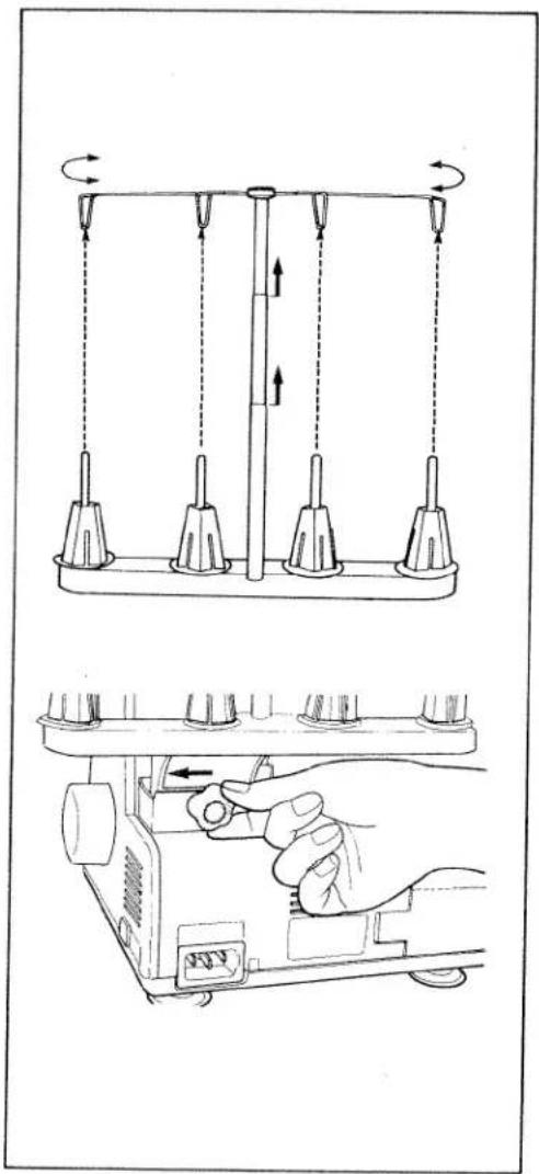
Technical line drawing showing a mechanical device with rotating arms and a hand adjusting the base panel (no text or symbols)Preparing for threading
Adjustment of thread reel stand: Loosen the adjusting knob on the thread reel stand, slide it to the left and tighten it.
Adjustment of thread guides: Pull up the thread guide bar and align it so that the thread guides are directly above the reel stand.

natural_image
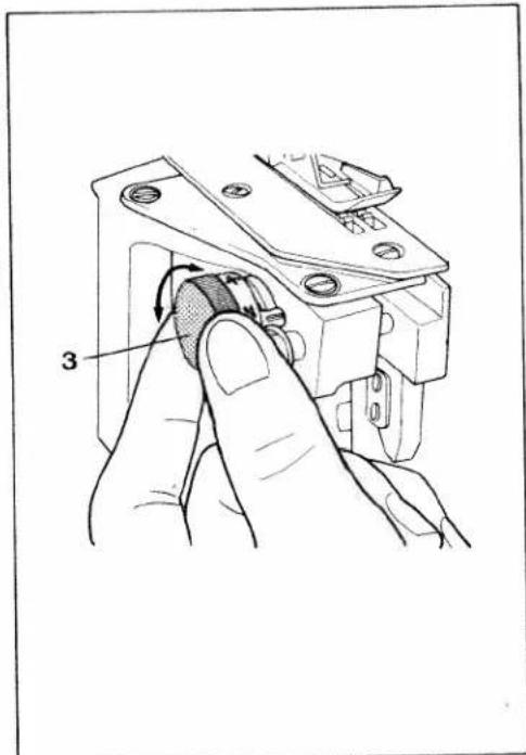
Illustration of a hand pressing down on a mechanical component with an arrow indicating force (no text or symbols present)Carrying handle and thread guide bar behind it:
Insert fingers into the groove of the carrying handle and pull it up. This movement automatically raises the thread guide bar.
natural_image
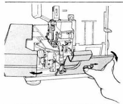
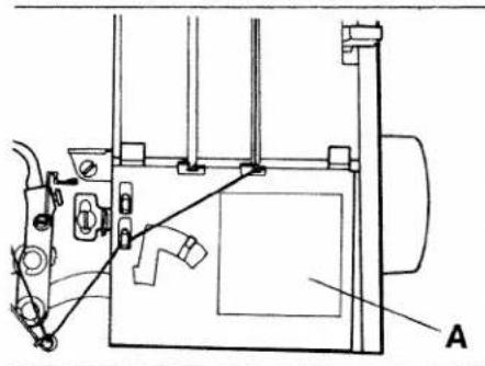
Technical line drawing of a sewing machine with hand operating the base (no text or symbols)Opening and closing looper cover and work support:
Push looper cover lever to the right, swing cover in the direction of the arrow and lower it.
To close the looper cover, push the cover until it locks.
To open the work support, push it to the left. To close the work support, push it to the right until it locks.
A threading diagram is affixed to the machine (A).
natural_image
Technical line drawing of a mechanical assembly with labeled component A (no text or symbols present)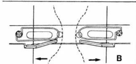
natural_image
Technical diagram showing two mechanical components with directional arrows, no text or symbols present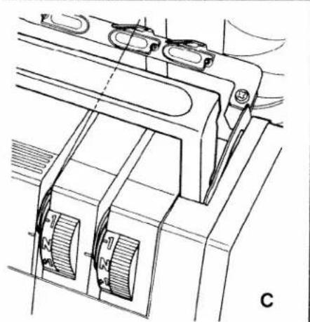
natural_image
Technical line drawing of a mechanical assembly with no visible text or symbolsThreading procedure
Threading must be done correctly to obtain a well-formed seam. Thread the machine in the following sequence:
-
Left looper (yellow)
-
Right looper (red)
-
Right needle (green)
-
Left needle (blue)
Diagram B shows threading of the thread guides behind the carrying handle.
Diagram C shows threading of the thread tension dials.
Now pull the respective thread into the corresponding guides and tension discs.

text_image
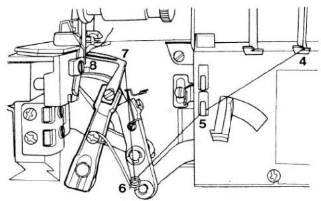
1 2 3 A4-thread safety stitch seam
For sewing and finishing two layers of fabric.
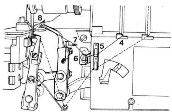
Threading the left looper:
Turn the handwheel towards ycu until the left looper is in its farthest right position (see illustration below).
Thread the left looper in sequence 1, 2, 3, 4, 5, 6, 7, 8 and pull approximately 10 cm (4") of thread through the looper eye (the thread path is marked yellow).
text_image
Technical diagram of a mechanical assembly with numbered components, likely for assembly or maintenance instructions.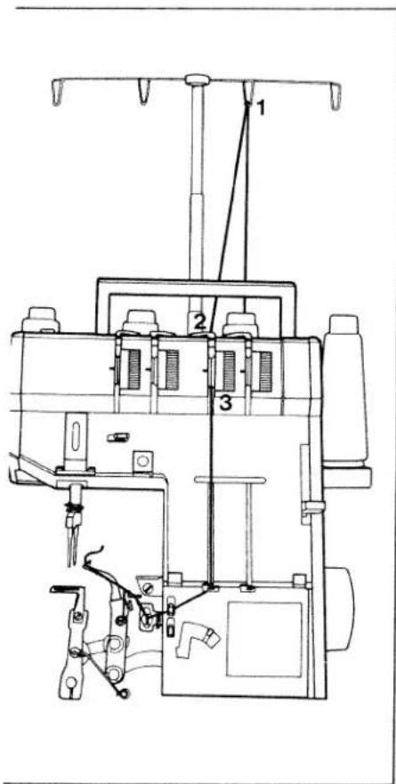
text_image
Technical diagram of a sewing machine with numbered components and labeled partsThreading the right looper:
Turn the handwheel towards you until the right looper is in its farthest right position (see illustration below).
Thread the right looper in sequence 1, 2, 3, 4, 5, 6, 7, 8 and pull approximately 10 cm (4") of thread through the looper eye (the thread path is marked red).
text_image
Technical diagram of a mechanical assembly with numbered components for identification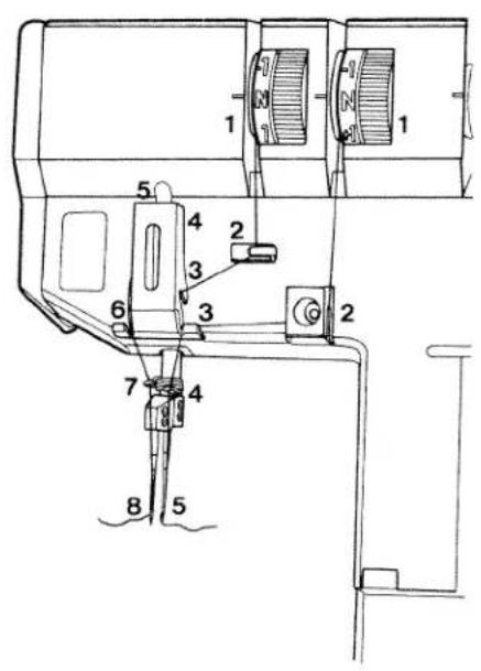
text_image
Technical diagram of a sewing machine with numbered components for identificationThreading the right needle:
Thread the right needle in sequence 1, 2, 3, 4, 5 and pull approximately 10 cm (4") thread through the needle eye (the thread path is marked green).
Thread the left needle in sequence 1, 2, 3, 4, 5, 6, 7, 8 and pull approximately 10 cm (4") thread through the eye of the left needle (the thread path is marked blue).

text_image
Technical diagram of a mechanical device with numbered components and labeled parts
text_image
Technical diagram of a sewing machine with numbered components labeled 1, 2, and 3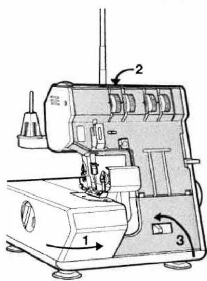
text_image
Technical diagram of a sewing machine with labeled parts 1, 2, and 3 indicating components and directional arrows.Now close the work support (1), push the handle down (2) and close the looper cover (3).
text_image
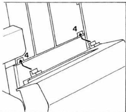
Technical diagram showing a mechanical assembly with labeled components 4 and numbered partsInserting the lint box:
Insert the tabs of the lint box into the slots (4) of the front cover.
natural_image
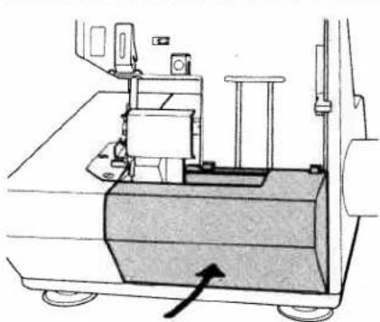
Technical line drawing of a mechanical device with a base and wheels, no visible text or symbolsPush the lint box up against the front cover until it snaps in place.
Use the reverse order to remove lint box.
natural_image
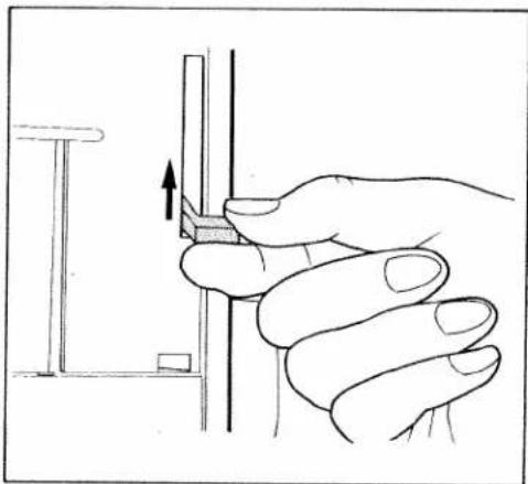
Hand holding a tool with an arrow indicating direction, no text or symbols presentSewing a test sample
After threading, a test sample should be sewn.
Raise presser foot lever, as shown in illustration.
natural_image
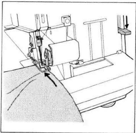
Line drawing of a sewing machine needle stitching fabric, showing mechanical components and fabric layers (no text or symbols)Place a piece of fabric under the needle and lower presser foot.

natural_image
Line drawing of a sewing machine needle stitching fabric (no text or symbols)Hold thread ends with your left hand while turning hand wheel counter-clockwise with your right hand. Make sure that threads have interlocked correctly.
natural_image
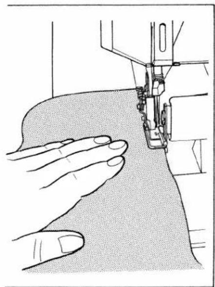
Illustration of a sewing machine needle stitching fabric, showing hands operating the seam (no text or symbols)Points to observe during sewing
Place the fabric completely under the presser foot when starting to sew. (Also after the machine has been re-threaded).
Sew the first stitches slowly.
Since the fabric is fed automatically, do not pull or push the fabric. Use your hand for guiding the fabric only.

natural_image
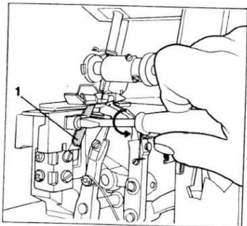
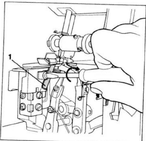
Technical line drawing of a mechanical assembly with no visible text or symbolsFinishing seam
Sew approximately 10 cm (4") beyond the end of the seam and use the thread cutter (1) behind the presser foot to cut the thread chain.

text_image
Technical diagram of a sewing machine with labeled component '1' and hand gestureSecuring the seam:
Knot the thread chain. In case of knitted fabrics, a crochet needle can be used in order to pull the thread chain into the seam.
Or:
Sew approximately 3 cm (1") beyond the seam. Raise presser foot. Flip fabri over. Lower presser foot and sew over the seam approximately 2 cm ( 12 ") without cutting the chain.
Sewing very heavy fabrics and different thicknesses of fabric:
This machine will sew through very thin to very heavy fabrics. When sewing very heavy fabrics, tighten the upper knife screw.
natural_image
Technical line drawing of a sewing machine with a hand operating the mechanism (no text or symbols present)Note:
When sewing thin fabrics, loosen the upper knife screw after sewing on heavy fabrics. (See illustration).
ainstitch seam

text_image
Top side Bottom side/eredge seam
text_image
Top side Bottom sideSetting thread tension:
The thread tension should be adjusted according to fabric type and thread size.
Examine the seam and make the necessary tension adjustments.
Adjusting thread tension:
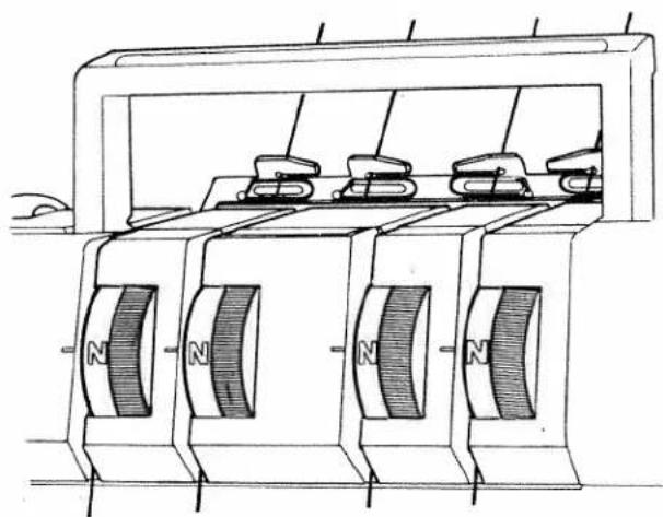
Set all thread tension dials to "N", standard setting. (See illustration below).
Sew a test sample to be sure that the correct tension has been obtained. (See illustrations on the left).
natural_image
Technical line drawing of a mechanical device with multiple magnets and housing (no text or symbols)
natural_image
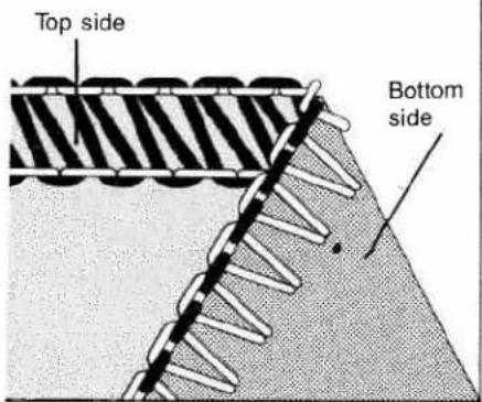
Geometric diagram showing a triangular prism with a dashed line intersecting it, no text or symbols present.When the thread tension is turned in (+) direction, the tension is increased. When turned in (−) direction, it is decreased.
Incorrect thread tension:
The left needle thread is too loose (blue thread tension).

natural_image
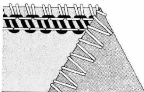
Diagram of a mechanical or structural assembly with diagonal grooves and a central rod, no text or symbols present.The right needle thread is too tight (green thread tension), or the right overedge looper thread is too loose (red thread tension).
natural_image
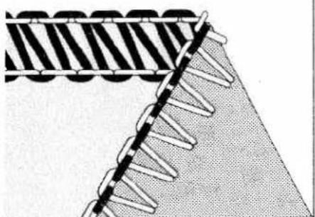
Diagram of a coiled spring or rope structure with layered material (no text or symbols)The right needle thread is too loose (green thread tension), or the right overedge looper thread is too tight (red thread tension).

natural_image
Diagram of a mechanical or structural assembly with layered components and a diagonal line (no text or symbols)The following seams can be sewn with this machine:
1. Four-thread safety stitch seam
This seam is sewn with all four threads. It should be used to sew light to medium weight fabrics.
Application: Closing seams, sewing sleeves into shirts and blouses, sewing curtains and drapes, etc.

natural_image
Diagram showing a triangular section with a dashed line and a wavy line intersecting it, no text or symbols present.2. Two-thread chainstitch seam
Only the left needle JL x 1 and the left chainstitch looper are threaded. The right overedge looper is disengaged and the right needle removed (see pages 18, 19).
Application: Seaming materials. By sewing the two-thread chainstitch seam, you can place the safety stitch at any distance from the edge you choose to give you a virtually unlimited seam width.
natural_image
Diagram showing a meshed structure with diagonal striped pattern and serrated edges (no text or symbols)3. Two-thread overedge seam
Only the right needle DB x 1 (1738) and the right overedging looper are threaded for this seam. The left needle is removed.
Application: Finishing all types of seams.
natural_image
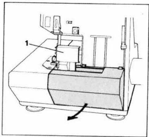
Technical line drawing of a mechanical device with labeled component 1 and directional arrow (no text or symbols beyond labels)Setting the machine for double chain-stitch
Remove the lint box, see page 11. Open looper cover. Remove knife guard (1) from the looper cover. Remove right needle.

natural_image
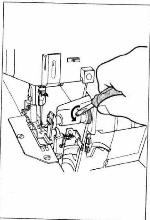
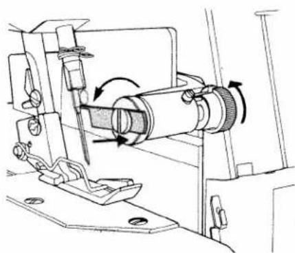
Technical line drawing of a sewing machine mechanism with no visible text or symbolsRaising the upper knife:
Turn the hand wheel counter-clockwise to set the knife in the highest position. Push the knife holder to the far right and turn the knob clockwise until it locks.
natural_image
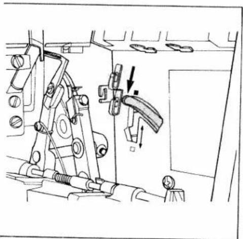
Technical line drawing of a mechanical assembly with no visible text or symbolsDisengaging the right overedge looper: Turn the hand wheel counter-clockwise until the needle is in the lowest position. Press the looper disengaging lever down.
Caution: The overedge looper is now disengaged and should no longer move when you turn the hand wheel.
natural_image
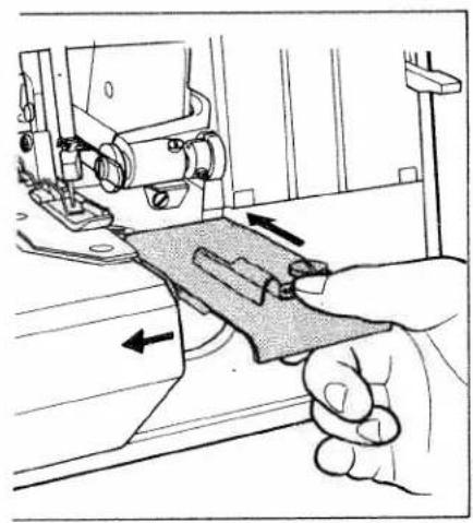
Illustration of a sewing machine needle stitching fabric, with arrows indicating fabric movement (no text or symbols)Inserting the fabric guide plate:
Open the work support. Insert the fabric guide plate as shown in the illustration.
Close the looper cover and work support.
natural_image
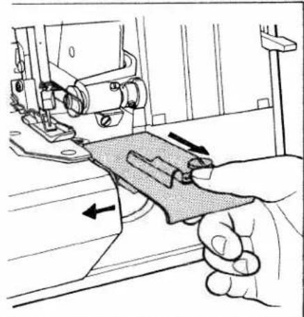
Illustration of a hand using a sewing machine to adjust fabric or material (no text or symbols visible)After sewing the two-thread chainstitch seam, set the machine for overedge seaming as follows:
Open the looper cover. Open the work support and remove the fabric guide plate.
Turn the hand wheel counter-clockwise until the needle is in the lowest position. Press the looper disengaging lever up (illustration below). Now the overedge looper is engaged. Insert DB x 1 (1738) needle.
Set the upper knife in the normal cutting position. Insert the knife guard in the looper cover and close it. Close work support and attach the lint box.

natural_image
Illustration of a hand inserting a component into a device panel (no text or symbols visible)Thread chart
| Material weight | Material type | Stitch type | Thread | Stitch length |
| Light fabrics | Organdy, light knit fabrics, taffeta, lining, silk, etc. | Chainstitch | CottonSize 80-100SyntheticsSize 70-140 | 2-3 mm |
| Overedge stitch | CottonSize 80-100SilkSize 80-100SyntheticsSize 70-140 | 3-4 mm | ||
| Medium fabrics | Cotton, medium knits, linen, satin, dress fabrics, etc. | Chainstitch | CottonSize 60-100SilkSize 50-100SyntheticsSize 70-140 | 2-3 mm |
| Overedge stitch | CottonSize 60-100SilkSize 50-100SyntheticsSize 70-140 | 3-4 mm | ||
| Heavy fabrics | Tweed, coat fabrics, cotton twill, heavy outerwear fabrics, etc. | Chainstitch | CottonSize 40-60SilkSize 40-60SyntheticsSize 70-140 | 2-4 mm |
| Overedge stitch | CottonSize 40-60SyntheticsSize 70-140 | |||
| Knit fabrics | Chainstitch | CottonSize 40-50SilkSize 50-100SyntheticsSize 70-140 | 2-3 mm | |
| Overedge stitch | SyntheticsSize 70-140 |
natural_image
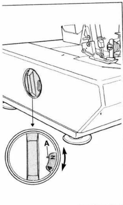
Technical diagram of a sewing machine's side panel showing adjustment mechanism (no text or symbols)Adjusting the stitch length:
The stitch length is regulated by turning the stitch length dial. The numbers indicate the stitch length in mm. The normal stitch length is "N".
A = The red mark on the dial is the setting mark.

natural_image
Line drawing of a mechanical device with directional arrows indicating motion (no text or symbols)Sewing foot pressure:
Position "N" of the foot pressure dial is the standard sewing foot pressure. It is normally reset only for very thin or heavy fabrics.
Thin fabrics:
Reduce the sewing foot pressure by setting to a lower number.
Heavy fabrics:
Increase sewing foot pressure by setting to a higher number.
text_image
Technical diagram showing a hand operating a sewing machine with labeled parts 1 and 2, including directional arrows indicating movement.Adjusting seam width:
Standard setting is 3.5 mm. The seam width can be changed from 2.5 to 7.0 mm, according to fabric type and seam requirements.
Note:
Before adjusting the stitch width, always disengage the upper knife.
To disengage upper knife, open looper cover. Push upper knife holder (1) to the far right. Turn knurled knob clockwise (2) until it clicks.
text_image
3Choose the required seam width by turning the stitch width dial (3). Normal stitch width is "N". Reset the upper knife to the lower (cutting) position and close the looper cover.
Sew a test sample.
Note:
After adjusting the seam width, it may be necessary to reset the thread tension.
natural_image
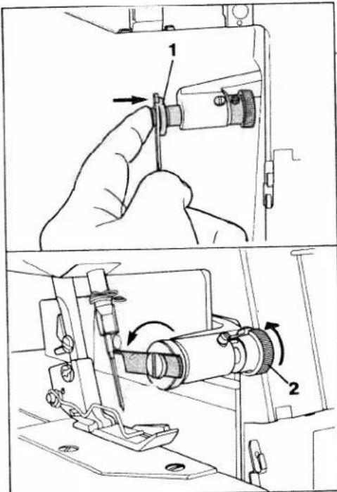
Line drawing of a sewing machine needle being adjusted, showing hands operating the mechanism (no text or symbols present)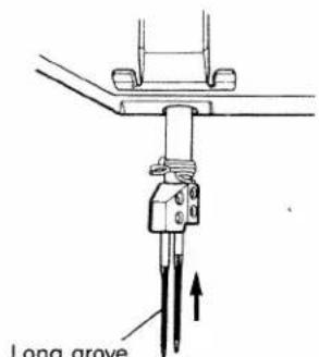
text_image
Long groveLong grove facing front
Machine care
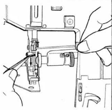
Removing needle:
Unplug the machine.
Turn the hand wheel counter-clockwise to raise the needle bar to its highest position. Loosen the needle clamp screw with the allen wrench and pull the needle out.
Inserting needle:
When the needle bar is at the highest position, insert a new needle in the needle holder, making sure that the groove of the needle faces you. Push the needle up as far as it will go and tighten the needle clamp screw.
Notes:
Use only System JL x 1 (black) needles for the left needle and System DB x 1 or 1738, for the right needle.
Although the correct needle size depends on the fabric and thread used, a size 14 needle is recommended.
An incorrectly inserted needle will cause thread breakage and skipped stitches.
Important:
Left needle = JL needle;
Right needle = DB needle
(JL needle is black).
natural_image
Mechanical assembly diagram showing a rotating shaft and housing mechanism (no text or symbols)Changing knives
Knives are available as spare parts and should be replaced when they are blunt.
Removing lower knife:
Unplug the machine.
Raise the needle bar. Push the upper knife holder to the far right and turn the knob clockwise until it clicks.
natural_image
Technical line drawing of a mechanical assembly with no visible text or symbolsLoosen knife clamp screw (1) and pull the lower knife down.
natural_image
Line drawing of a finger pressing down on a mechanical component with an arrow indicating force (no text or symbols)Inserting lower knife:
Insert a new knife into the groove of the lower knife holder with the cutting edge facing right.
Set the knife so that the cutting edge aligns with the surface of the needle plate.
natural_image
Technical line drawing of a mechanical assembly with a hand operating a tool (no text or symbols present)Tighten the lower knife clamp screw (1). Return the upper knife to its normal position.

natural_image
Mechanical assembly diagram showing a rotating shaft and housing mechanism (no text or labels)Changing upper knife:
The upper knife is carbide tipped and will not need to be replaced with normal use. It has to be replaced only when the cutting edge has been damaged.
Unplug the machine.
Push the upper knife holder to the far right and turn the knob clockwise until it clicks.

natural_image
Mechanical assembly diagram showing a tool interacting with a mechanical component (no text or symbols visible)Unscrew the knife retaining screw and remove the upper knife.

text_image
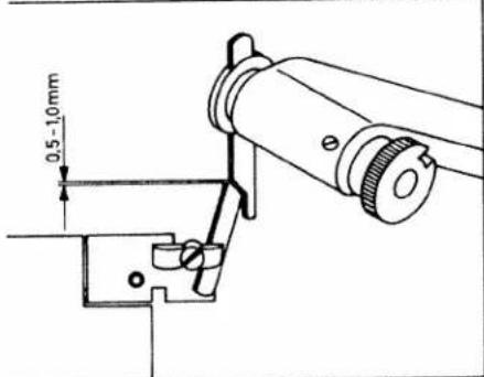
Technical diagram of a mechanical assembly with labeled parts 1 and 2To replace the upper knife, insert the retaining screw through cutout (1) of the knife. Screw it into threaded hole (2) of the knife holder. Tighten slightly and set the upper knife in cutting position.
Turn the hand wheel of the machine until the upper knife arm is in the lowest position. The front edge of the upper knife should be 0.5 to 1.0 mm lower in this position than the surface of the needle plate. Tighten the retaining screw securely.
text_image
0.5 - 1.0mm
natural_image
Hand inserting a component into a device (no text or symbols visible)- Changing the light bulb:
Unplug the machine.
Remove the retaining screw from t. light cover and swing cover to the
text_image
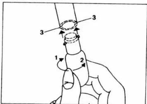
1 2 3 3Turn the bulb in direction (1) and remove it. Insert the new bulb with into slots (3). Push bulb up and turn in direction (2).
Replace cover.
Caution: Use a 15 watt bulb only.
natural_image
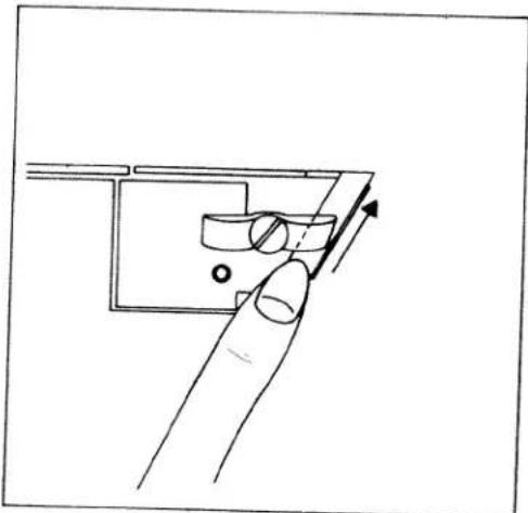
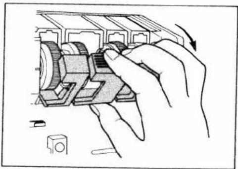
Illustration of hands assembling a mechanical component with a curved arrow indicating rotation (no text or symbols present)Cleaning thread tensions
Flip the tension cover down.
natural_image
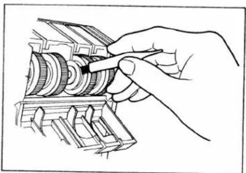
Hand turning a mechanical gear assembly (no text or symbols visible)Use the brush provided with the accessories to remove dust and lint from the discs.
Close the tension cover.
viling the machine:
Always clean the machine of lint and dust prior to oiling.
Use only one to two drops of good quality sewing machine oil at the places indicated (Fig. 1).
Since the bushings are oil impregnated, they need to be oiled only once or twice a month. (Fig. 2).

natural_image
Technical line drawing of a mechanical assembly with no visible text or symbols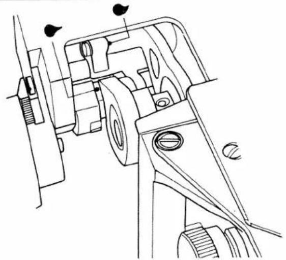
natural_image
Technical line drawing of a mechanical assembly with no visible text or symbols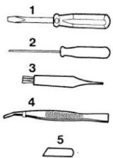
text_image
1 2 3 4 5

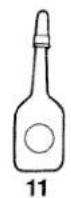
Accessories
1 Screwdriver
2 Wrench
3 Lint brush
4 Tweezers
5 Lower knife
6 Fabric guide plate
7 Edge guide
8 Retaining screw for 7
9 Thread unreeling disc
10 Needles
11 Oil
Optional accessories:
(not illustrated)
Blindhem foot
Elastic foot
Specifications
Max. sewing speed 1,300 stitches/min.
Seam width 3.0-7.0 mm
Stitch length 1-5 mm
Sewing foot snap-on
Lubrication manual
Needle system JL x 1 and DB x 1 (or 1738)
Dimensions (sizes 9-14)
Dimensions 24 x 22 x 18.5 cm
Weight approx. 8,5 kg
(19 lbs.)
Sewing problems and solutions (see next page)
This machine is easy to operate and there are no difficult adjustments to be made. Problems, similar to the ones described, occur because of simple adjustment errors. They can easily be corrected by the solutions offered.
| Problem | Cause | Solution |
| Machine does not feed material properly | Sewing foot pressure on material too light | Turn sewing foot pressure screw clockwise to increase pressure. Check result on each adjustment. |
| Needle breaks frequently | 1. Needle is bent2. Needle not correctly inserted3. Fabric is pulled during sewing | Replace damaged needle with a new one.Insert new needle correctly.Do not pull or push material during sewing. |
| Thread breaks frequently | 1. Machine incorrectly threaded2. Thread knots itself3. Thread tension too tight4. Needle not correctly inserted5. Wrong needle used | Thread machine correctly (see pages 7-11).Rethread needle.Set tension correctly (see pages 15, 16).Insert needle correctly (see page 23).Use recommended needle (see page 23). |
| Machine skips stitches | 1. Needle bent or point broken off2. Needle not correctly inserted3. Wrong needle used4. Machine incorrectly threaded.5. Sewing foot pressure on material too light. | Insert new needle.Insert needle correctly (see page 23).Use recommended needle (see page 23).Thread machine correctly (see pages 7-11).Increase sewing foot pressure. |
| Machine does not work properly | Thread tensions incorrectly set | Set tensions correctly (see pages 15, 16). |
| Material puckers | Thread tension too tightMachine incorrectly threaded or thread has caught. | For sewing light materials the thread tension is set as low as possible to ensure correct stitch formation.Thread machine correctly (see pages 7-11) or check the path of the thread. |

text_image
Technical diagram of a sewing machine with labeled parts and directional arrows indicating movement or forceChanging the sewing feet
Push lever A up slightly (Fig. 1), and the presser foot will snap out.
Place the rolled hem foot under the presser foot holder so that crosspiece B of the rolled hem foot engages in groove C of the holder (Fig. 2). Push the presser foot lever down and with the other hand gently push lever A up until the foot snaps on.

text_image
C B 2