hobbylock 794 - Sewing machine PFAFF - Free user manual and instructions
Find the device manual for free hobbylock 794 PFAFF in PDF.

User questions about hobbylock 794 PFAFF
0 question about this device. Answer the ones you know or ask your own.
Ask a new question about this device
Download the instructions for your Sewing machine in PDF format for free! Find your manual hobbylock 794 - PFAFF and take your electronic device back in hand. On this page are published all the documents necessary for the use of your device. hobbylock 794 by PFAFF.
USER MANUAL hobbylock 794 PFAFF
natural_image
Black and white industrial sewing machine with visible branding and mechanical components (no readable text or symbols)Notes on safety
A) Due to the up and down movement of the needle, the user must take sufficient care to avoid injury and observe the sewing area continuously while sewing.
B) When leaving the machine, changing parts or accessories, the machine must be disconnected from the power source.
C) The maximum approved wattage of the light bulb is 15 watts.
D) The drive belt must never be adjusted by anyone but an authorized Pfaff agent.
Contents
The controls of the sewing machine 2,3
Accessory box 4
Electrical connection 4,5
Foot control 5
Preparing for threading 6,7
Threading, 4-thread double-overedge seam 7-11
Threading right looper 8
Threading left looper 9
Threading the needles 10
Inserting the lint box 11
Sewing test 12
Points to observe during sewing 13
Securing the seam 14
Checking and adjusting thread tension 15, 16
3-thread overedge seam 17
Thread chart 18
Adjusting the stitch length on 794 18
Adjusting the stitch length on 796 19
Adjusting the differential feed on 796 20.21
Regulating the sewing foot pressure 18
Adjusting the seam width 22
Changing the sewing feet. 23
Sewing rolled hems 24, 25
Changing needles 26
Changing lower knife 26, 27
Changing upper knife 28
Changing light bulb 29
Cleaning the thread tensions 29
Oiling the machine 30
Sewing problems and solutions 31
Accessories 32
Specifications 32
text_image
Technical diagram of a sewing machine with numbered parts for identification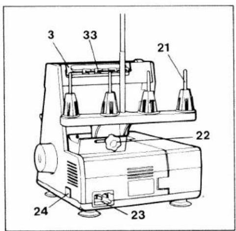
text_image
3 33 21 22 24 23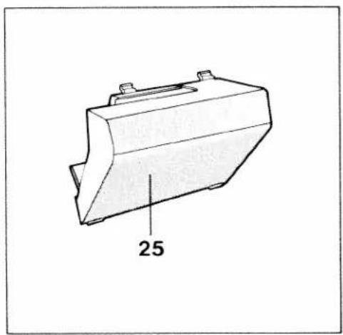
natural_image
Technical line drawing of a mechanical component with a dimension label '25' (no text or symbols beyond the number)Controls of the sewing machine
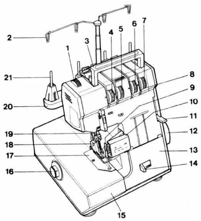
1 Foot pressure regulating dial
2 Thread guide
3 Carrying handle
4 Left needle thread tension dial
5 Right needle thread tension dial
6 Right looper thread tension dial
7 Left looper thread tension dial
8 Thread tension cover
9 Upper knife
10 Knife guard
11 Presser foot lifter lever
12 Hand wheel and feed regulator
13 Looper cover
14 Looper cover lever
15 Work support
16 Stitch length setting key on 794 Differential feed setting on 796
17 Needle plate
18 Presser foot
19 Needle bar
20 Thread reel stand
21 Thread reel pins
22 Adjusting knob
23 Machine plug socket
24 Master switch
25 Lint box
26 Foot control
27 Foot control plug
28 Mains plug
29 Lower knife
30 Knife clamp screw
31 Right looper
32 Left looper
33 Thread guide bar

text_image
28 26 27
text_image
9 31 32 30 29
natural_image
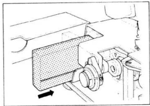
Mechanical assembly diagram showing hands operating a component with a directional arrow (no text or symbols)Accessory box
Swing the work support to the left and pull out the accessory box.
natural_image
Mechanical assembly diagram showing a component with a textured block and rotating parts (no text or symbols)To replace the accessory box, slide it into the grooves and push it until it locks. The accessories are illustrated on page 32.

natural_image
Line drawing of a sewing machine connected to a cable and a connector (no text or symbols present)Electrical connection
Use this machine only on a flat surface or on a special sewing table.
Attaching the foot control: Insert the plug of the control into the machine plug socket. Then connect the mains plug to a power source.
Caution: When the machine is not in use, disconnect plug from power source. Do not place any objects on the foot control.
natural_image
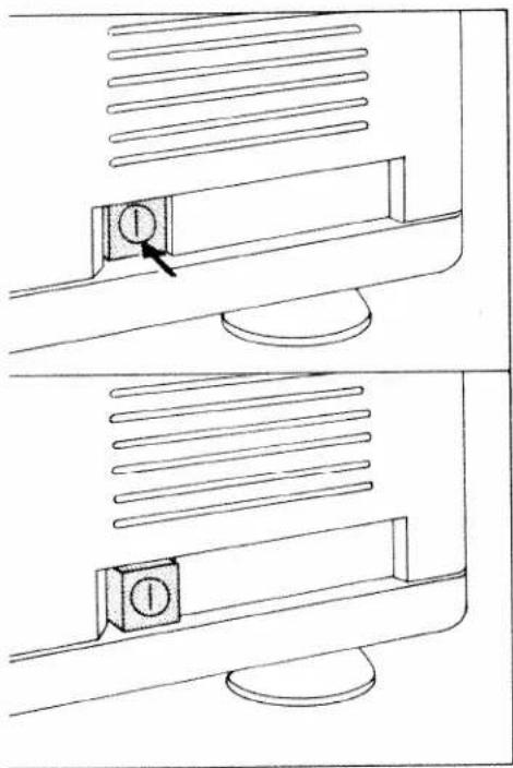
Technical line drawing showing two views of a computer monitor with a labeled button (no text or symbols present)Switching the machine ON and OFF
Power and sewing light are switched on and off simultaneously with the master switch.
Switching on:
Press switch. Machine and sewing light are switched on.
Switching off:
Press switch again. Machine and sewing light are switched off.
text_image
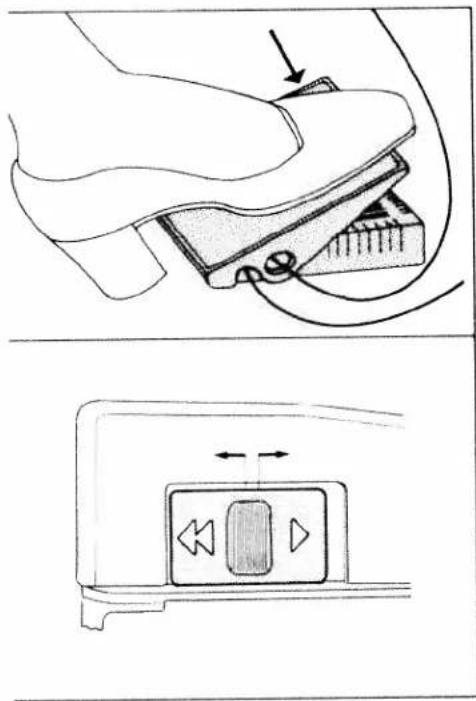
Technical diagram showing a device with labeled components and directional arrows indicating movement or force.Foot control
The speed of the Hobbylock is regulated as follows:
When pressing the foot control gently, the machine will run at low speed; when pressing harder, it will run faster.
Electronic foot control
Maximum speed is adjusted in two grades by the switch on the foot control.
Position ▶ = Half speed
Position ◀◀ = Full speed

natural_image
Technical line drawing showing a mechanical device with rotating arms and a hand operating it (no text or symbols present)Preparing for threading
Adjustment of thread reel stand: Loosen the adjusting knob on the thread reel stand, slide it to the left and tighten it.
Adjustment of the thread guides: Pull up the thread guide bar and align it so that the thread guides are directly above the reel stand.

natural_image
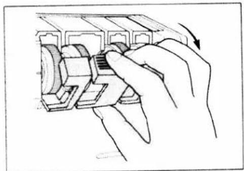
Hand pressing a component into a device (no text or symbols visible)Carrying handle and thread guide bar behind it:
Insert fingers into the groove of the carrying handle and pull it up. This movement automatically raises the thread guide bar.

natural_image
Line drawing of hands operating a mechanical device with a directional arrow (no text or symbols)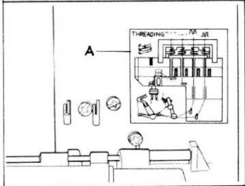
text_image
A THREADING M M MOpening and closing looper cover and work support
Push looper cover lever to the right, swing cover in the direction of the arrow and lower it.
To close the looper cover, push the cover until it locks.
To open the work support, push it to the left. To close the work support, push it to the right until it locks.
A threading diagram is affixed to the machine (A).
natural_image
Technical diagram showing two mechanical components with directional arrows, no text or symbols present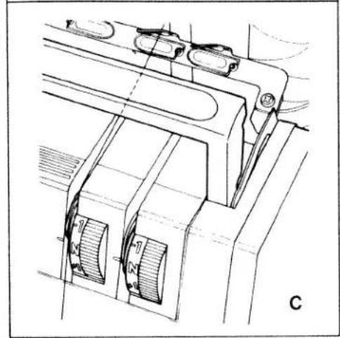
natural_image
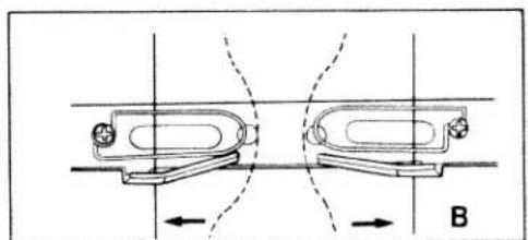
Technical line drawing of a mechanical assembly with no visible text or symbolsThreading procedure
Threading must be done correctly to obtain a well-formed seam. Thread the machine in the following sequence:
- Right looper (red)
- Left looper (orange)
- Right needle (green)
- Left needle (blue)
Diagram B shows threading of the thread guides behind the carrying handle.
Diagram C shows threading of the thread tension.
Now pull the respective thread into the corresponding guides and tension discs.

text_image
Technical diagram of a sewing machine with numbered components for identification4-thread double overedge seam
For sewing and finishing two layers of fabric.
Threading the right looper:
Thread the right looper in sequence 1 to 10 and pull approximately 10 cm (4") of thread through the looper eye (the thread path is marked red).
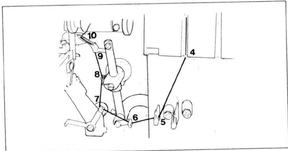
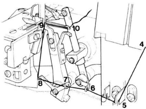
text_image
10 9 8 7 6 5 4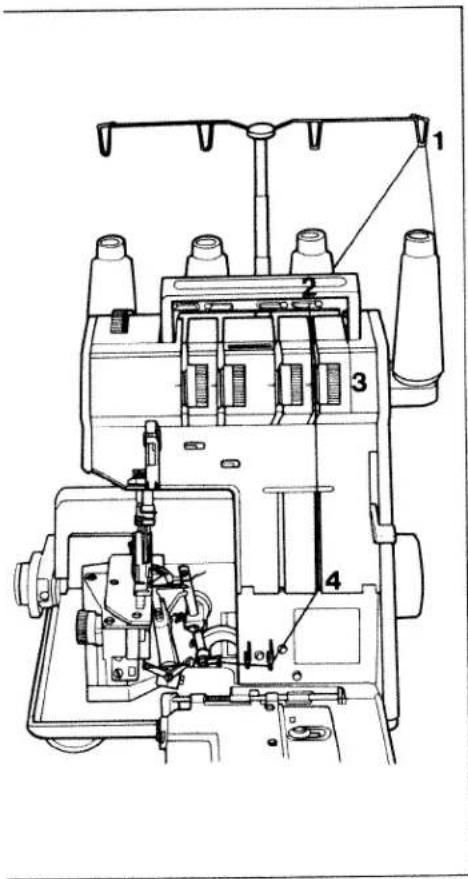
text_image
Technical diagram of a sewing machine with numbered components for identificationThreading the left looper: Insert the left looper thread in sequence 1 to 10 and pull approximately 10 cm (4") of thread through the looper eye (the thread path is marked orange).
text_image
Technical diagram of a mechanical linkage system with numbered components
text_image
1 2 3 4 5 6 7 AThreading the right needle:
Thread the right needle in sequence
1 to 7 and pull approximately 5 cm of thread through the eye of the needle.
(The thread path is marked green.)
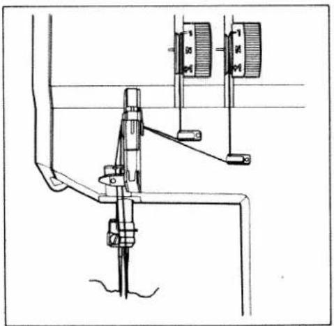
Make sure to thread point 4 with special care; insert the thread behind hook A of the thread guide plates fitted on both sides.

text_image
Technical diagram of a sewing machine with numbered components for identificationThreading the left needle:
Thread the left needle in sequence
1 to 7 and pull approximately 5 cm of thread through the eye of the needle.
(The thread path is marked blue.)
Make sure to thread point 4 with special care; insert the thread behind hook A of the thread guide plates fitted on both sides.
natural_image
Technical line drawing of a mechanical device with no visible text or symbolsThe diagram shows the correctly threaded machine.

text_image
Technical line drawing of a sewing machine with labeled parts 1, 2, and 3 indicating mechanical components.Now close the work support (1), push the handle down (2) and close the looper cover (3).
text_image
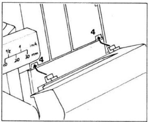
1/2 1 inch 10 20 30 mm 4 4Inserting the lint box:
Insert the tabs of the lint box into the slots (4) of the front cover.

natural_image
Technical line drawing of a mechanical device with an arrow indicating motion or force direction (no text or symbols present)Push the lint box up against the front cover until it snaps in place.
Use the reverse order to remove lint box.
natural_image
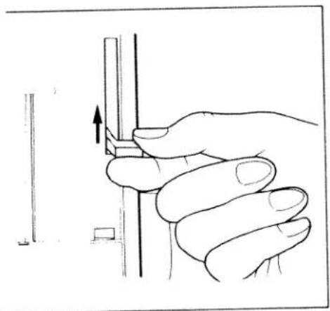
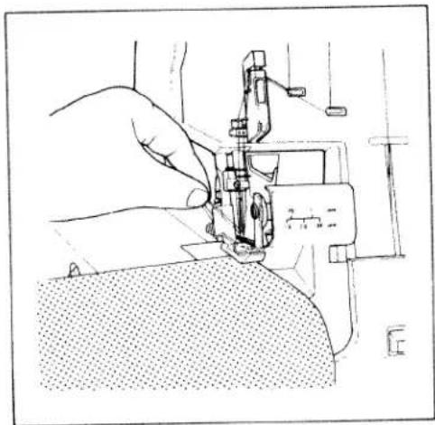
Illustration of a hand holding a tool with an arrow indicating direction (no text or symbols present)Sewing a test sample
After threading, a test sample should be sewn.
Raise presser foot lever, as shown in illustration.
natural_image
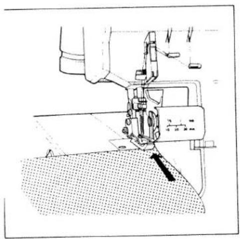
Line drawing of a sewing machine needle stitching fabric, showing no text or symbolsInsert test fabric and lower presser foot.
natural_image
Line drawing of a hand operating a sewing machine needle on fabric (no text or symbols)Hold thread ends with your left hand while turning hand wheel counterclockwise with your right hand. In doing so, the threads must be guided to the rear, under the presser foot. Make sure that threads have interlocked correctly.
natural_image
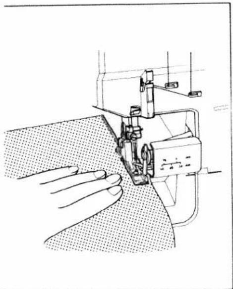
Line drawing of a sewing machine needle stitching fabric, with hands operating the component (no text or symbols present)Points to observe during sewing
Place the fabric completely under the presser foot when starting to sew. (Also after the machine has been re-threaded).
Sew the first stitches slowly.
Since the fabric is fed automatically, do not pull or push the fabric. Use your hand for guiding only.

natural_image
Line drawings showing hands operating a sewing machine with a tool, no text or symbols presentFinishing seam
Sew approximately 5 cm beyond the end of the seam and use the thread cutter (1) behind the presser foot to cut the thread chain.
Securing the seam:
Knot the thread chain. For knit fabrics, a crochet needle can be used to pull the thread chain into the seam.
To prevent ravelling of seams, sew approximately 3 cm (1") beyond the seam. Raise presser foot. Flip fabric over. Lower presser foot and sew over the seam approximately 2 cm (1/2") without cutting the chain.
Sewing very heavy fabrics and different thicknesses of fabric:
This machine will sew through very thin to very heavy fabrics. When sewing very heavy fabrics, tighten the upper knife screw.
natural_image
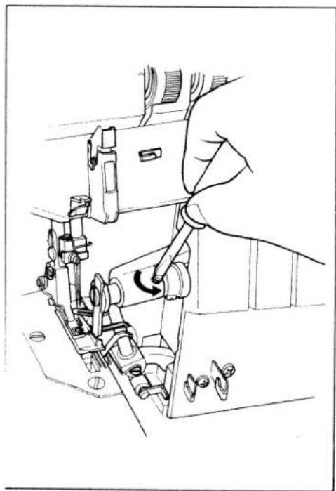
Line drawing of a hand operating a sewing machine with a rotary knob (no text or symbols)Note:
When sewing thin fabrics, loosen the upper knife screw after sewing on heavy fabrics. (See illustration).
text_image
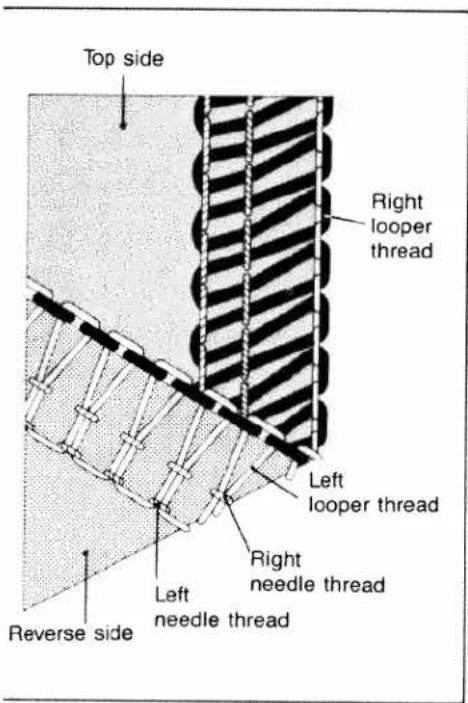
Top side Right looper thread Left looper thread Right needle thread Left needle thread Reverse sideSetting thread tensions:
The thread tension should be adjusted according to fabric type and thread size.
Examine the seam and make the necessary tension adjustments.
Adjusting thread tension:
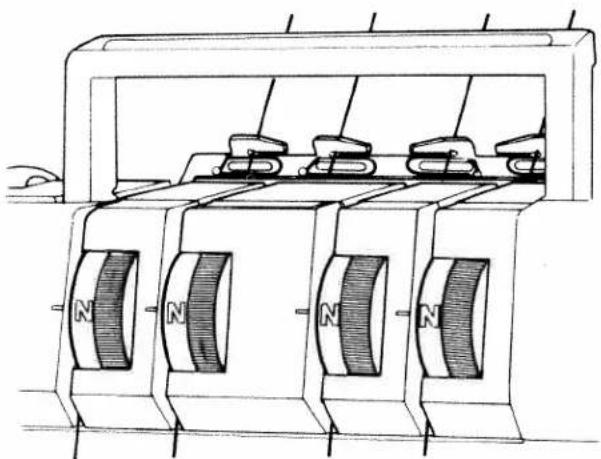
Set all thread tension dials to "N" (standard setting). See illustration below.
Sew a test sample to be sure that the correct tension has been obtained. See illustration above.
natural_image
Technical line drawing of a mechanical device with four magnetic poles and a central housing (no text or symbols)
text_image
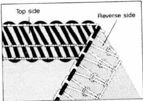
Top side Reverse sideWhen the thread tension is turned in (+) direction, the tension is increased. When turned in (-) direction it is decreased. Incorrect thread tension: The left needle thread is too loose (blue thread tension).
text_image
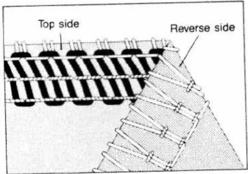
Top side Reverse sideThe right needle thread is too loose (green thread tension).
text_image
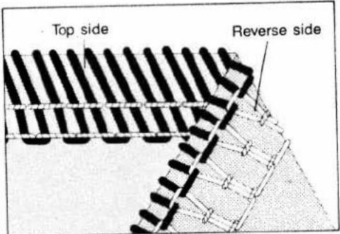
Top side Reverse sideThe right looper thread is too tight (red thread tension) or the left looper thread too loose (orange thread tension).
text_image
Top side Reverse sideThe left looper thread is too tight (orange thread tension) or the right looper thread too loose (red thread tension).
3-thread overedge seam
How to convert from four-thread to three-thread sewing:
Three-thread sewing is possible by using either right or left needles (see page 10).
Remove the needle that is not used (see page 26).
| 3-thread overedge seam | |||
| Needle thread | Left needle | Right needle | |
| Thread tension | Marked blue | Marked green | |
| Thread in needle clamp guides | 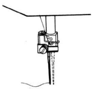 |  | |
| Standard seam width | 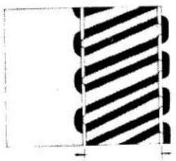 |  | |
| maximum seam width | 6.5 mm | 4.5 mm | |
| Thread chart | |||
| Material | Thread | Stitch length | |
| Light materials:Organdy, light-knit fabric,Taffeta, silk,lining materials. | Cotton | No. 80-100 | 2.0 to 4.0 mm |
| Silk | No. 80-100 | ||
| Synthetic thread | No. 70-140 | ||
| Medium-heavy materials:Cotton, tricot,linen, dress materials | Cotton | No. 60-100 | 2.0 to 4.0 mm |
| Silk | No. 50-100 | ||
| Synthetic thread | No. 70-140 | ||
| Heavy materials:Tweed, suit materials,denim, heavy cloth | Cotton | No. 40-60 | 2.0 to 4.5 mm |
| Silk | No. 40-60 | ||
| Synthetic thread | No. 70-140 | ||
| Knit fabrics: | Cotton | No. 40-60 | 2.0 to 4.5 mm |
| Silk | No. 40-60 | ||
| Synthetic thread | No. 70-140 | ||
| Rolled hem | Polyester thread | No. 120/2 (180)Mercerized thread (bulk thread) | 1.5 to 2.5 mm |

natural_image
Diagram of a device with a curved arrow indicating rotational motion, no text or symbols presentSewing foot pressure:
Position "N" of the foot pressure dial is the standard sewing foot pressure. It is normally reset only for very thin or heavy fabrics.
Thin fabrics:
Reduce the sewing foot pressure by setting to a lower number.
Heavy fabrics:
Increase the sewing foot pressure by setting to a higher number.

text_image
16 AStitch lenght setting on 794
The stitch length is regulated by turning feed regulator 16. The numbers indicate the stitch length in mm which normally is N (3 mm).
A = setting mark.
natural_image
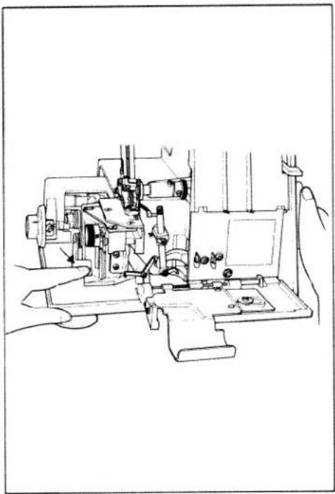
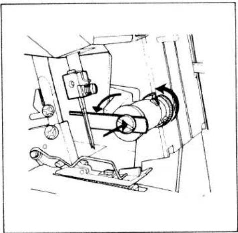
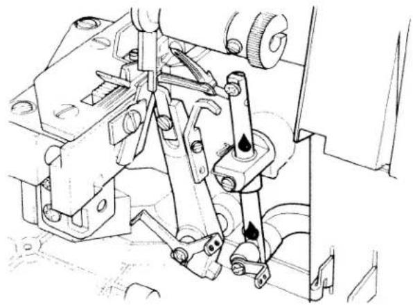
Line drawing of a sewing machine with hands operating it (no text or symbols)Setting the stitch length on 796
Open lateral swivel table 15. Press stop of main feed dog (see arrow) fully downwards and hold it there. Turn handwheel 12 in the direction indicated by the arrow until it snaps into place.
natural_image
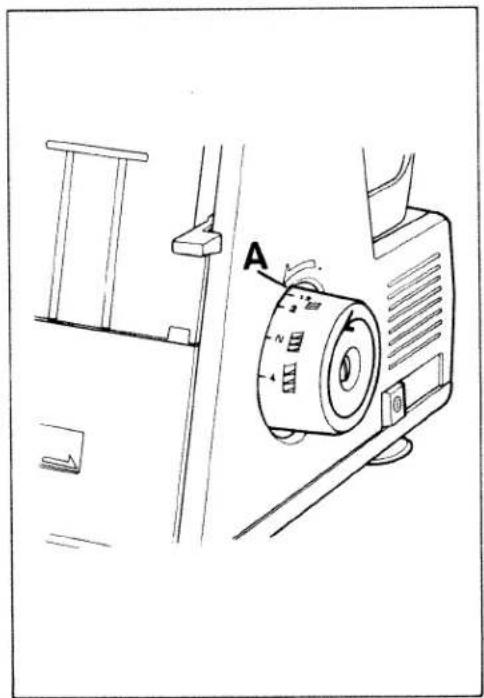
Technical line drawing of a mechanical device with labeled component A (no text or symbols beyond label)Set the required stitch length at mark A by continuing to turn handwheel 12 forwards or backwards, as may be required (point of arrow).
The numbers indicate the stitch length in mm which normally is N = 3 mm.
The stitch length is set firmly as soon as you release the stop of the main feed dog.

text_image
16
Adjusting the differential feed
The differential feed prevents inter-ply shift. It consists of two feed dogs, arranged one behind the other, which both pick up and move the workpiece at the same time.
The feed amount of either feed dog can be set separately. It is possible to have the workpiece moved more by the front feed dog than by the rear one and vice versa. Owing to that very good sewing results are accomplished. Set the differential feed according to the material you wish to process (see table on page 21). The following settings at button 16 are possible:
Setting 0.5 = Short stroke of front feed dog, long stroke of rear feed dog
Setting — = Same stroke of both feed dogs
Setting 1.5 = Long stroke of front feed dog, short stroke of rear feed dog
Setting 2 = Front feed dog set for longest possible stroke, rear feed dog set for shortest possible stroke
The differential feed can be set infinitely from 0.5 to 2, also during sewing.
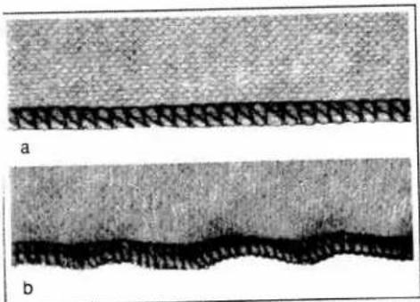
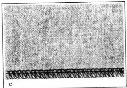
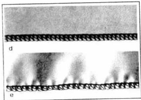
This table indicates possible settings of the differential feed. In order to make sure about the setting required for the fabric you wish to process a sewing test has to be made.
he differential feed can also be set during sewing.
| Setting of dif-ferential feed | Illustration | Correct seam | Fabric |
| 0.5 | 1 | a | Nylon, tricot, lining fabrics,popelin |
| — | 2 | c | Light cotton, jeans(normal fabrics) |
| 1.5 | 3 | d | Jersey, silk, medium cotton,nicki fabrics, light knittings |
| 2 | 4 | f | Heavy knitwear,very elastic fabrics |
natural_image
Two grayscale images labeled 'a' and 'b', showing textured surfaces with no visible text or symbols.III. 1
natural_image
Close-up of a textured surface with a dark horizontal band at the bottom (no text or symbols visible)III.2
natural_image
Two grayscale images labeled 'd' and 'e' showing textured surfaces with diagonal hatching patterns (no text or symbols)III. 3

natural_image
Microscopic view of two layered material structures labeled f and g, showing distinct wavy patterns (no text or symbols)III. 4
Gathering can be employed to obtain fashionable effects on garments (differential feed setting 2).

text_image
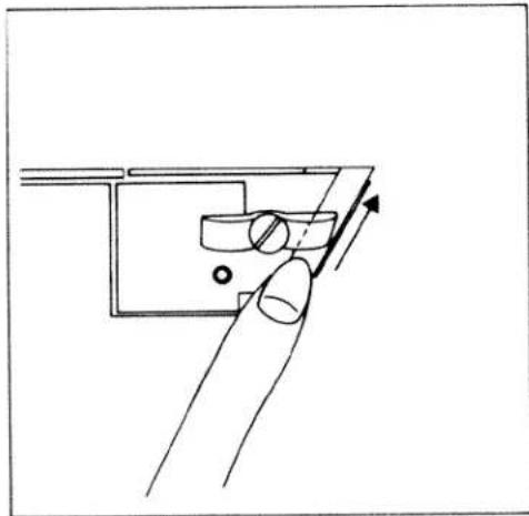
Technical diagram showing mechanical assembly steps with labeled components and directional arrowsAdjusting seam width:
Standard setting is 3.5 mm. The seam width can be changed from 2.5 to 6.5 mm, according to fabric type and seam requirements.
Note:
Before adjusting the stitch width, always disengage the upper knife.
To disengage upper knife, open looper cover. Push upper knife holder (1) to the far right. Turn knurled knob (2) clockwise until it clicks.

text_image
3Choose the required seam width by turning the stitch width button (3). Normal stitch width is "N". Reset the upper knife to the lower (cutting) position and close the looper cover.
Sew a test sample.
Note:
After adjusting the seam width, it may be necessary to reset the thread tension.
text_image
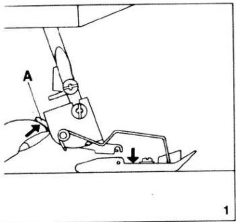
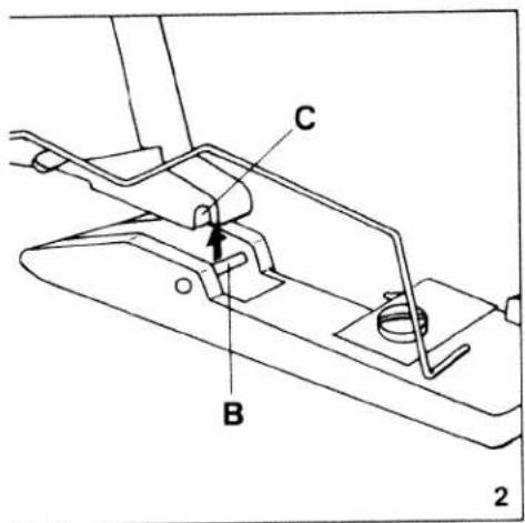
Technical diagram of a sewing machine with labeled parts and directional arrows indicating movement or positioning.Changing the sewing feet
Push lever A up slightly (Fig. 1), and the presser foot will snap out. Place the foot under the presser foot holder so that crosspiece B of the rolled hem foot engages in groove C of the holder (Fig. 2). Push the presser foot lever down and with the other hand gently push lever A up until the foot snaps on.
text_image
C B 2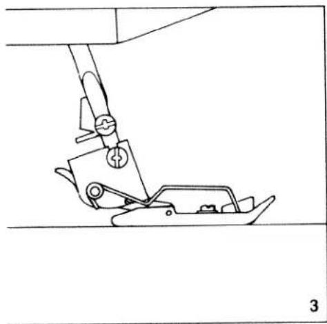
natural_image
Line drawing of a sewing machine needle and foot assembly (no text or symbols)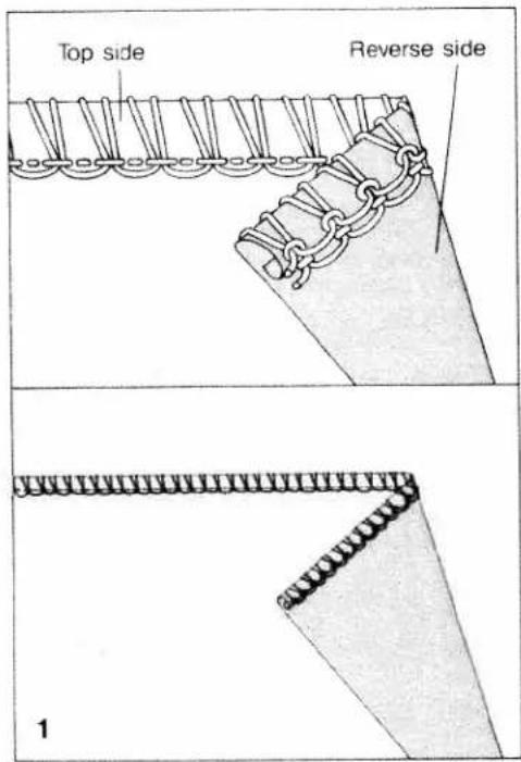
text_image
Top side Reverse side 1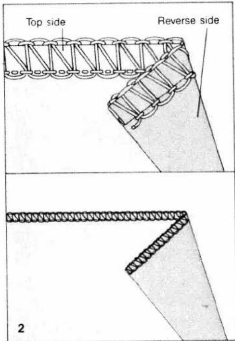
text_image
Top side Reverse side 2Rolled hem
Use a rolled hem on fine and delicate fabrics. A quick test to determine if the fabric is suitable for a rolled hem is to roll the fabric between thumb and index finger. If it rolls, the Pfaff Hobbylock will quickly produce a professional rolled hem.
- Remove left needle.
- Snap on rolled hem foot, marked with the letter "R", from accessory box.
- Use green, red, and orange threading paths only.
- Thread the above three threading paths with Mez Alcazar rayon thread for a rolled hem with a satin finish. Or use regular sewing thread, woolly nylon or any other good quality thread.
- Set stitch length at the shortest setting 1.
- Set stitch width at 2.5.
- Set green threading path (needle tension) at N.
- Set red threading path (upper looper tension) at +4 or +5, depending on the fabric used.
- Set orange threading path (lower looper tension) at +3 or +5, depending on the fabric used.
Flat hem
Use a flat hem on heavier fabrics that cannot be rolled. The Pfaff Hobbylock 794 is also perfect for this type of hem.
- Remove left needle.
- Snap on rolled hem foot, marked with the letter "R", from the accessory box.
- Use green, red, and orange threading paths only.
- Thread the above three threading paths with Mez Alcazar rayon thread for a hem with a satin finish. Or use regular sewing thread, woolly nylon or any other good quality thread.
- Set stitch length at the shortest setting I.
- Set stitch width at 2.5 for a narrow flat hem. Or set the stitch width at a higher setting for a wider hem.
- Set green threading path (needle tension) at N.
- Set red threading path (upper looper tension) at +3, +4, or +5, depending on the weight of the fabric.
- Set orange threading path (lower looper tension) at +2 or more, depending on the weight of the fabric.

natural_image
Line drawing of hands operating a sewing machine with a tool, no text or symbols present
text_image
Technical diagram showing mechanical assembly with labeled parts A and B, including directional arrows and a magnified view of component A.Changing needles
Removing needle:
Unplug the machine.
Turn the hand wheel counter-clockwise to raise the needle bar to its highest position. Loosen the needle clamp screw with the allen wrench and pull the needle out.
Inserting needle:
When the needle bar is at the highest position, insert a new needle in the needle holder, making sure the groove of the needle faces you and scarf A (centre of illustration) can be seen from the side. Push the needle up as far as it will go and tighten the needle clamp screw.
Notes:
System DB x 1, or 1738 needles are used with this machine.
Although the correct needle size depends on the fabric and thread used, a size 14 needle is recommended.
An incorrectly inserted needle will cause thread breakage and skipped stitches.
Always turn the machine OFF when changing needles.
natural_image
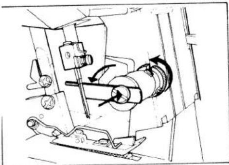
Technical line drawing of a mechanical assembly with rotating components and directional arrows (no text or symbols)Changing knives
Knives are available as spare parts and should be replaced when they are blunt.
Removing lower knife:
Unplug the machine.
Raise the needle bar. Push the upper knife holder to the far right and turn the knob clockwise until it clicks.

natural_image
Hand operating a mechanical assembly with gears and levers (no visible text or symbols)Loosen knife clamp screw (1) and pull the lower knife down.
natural_image
Line drawing of a hand holding a small object with an arrow indicating direction (no text or symbols)Inserting lower knife:
Insert a new knife into the groove of the lower knife holder with the cutting edge facing right.
Set the knife so that the cutting edge aligns with the surface of the needle plate.

natural_image
Hand operating a mechanical assembly with gears and tools (no visible text or symbols)Tighten the lower knife clamp screw.
Push upper knife to the right and turn to the front until it snaps into place (operative position).
natural_image
Technical line drawing of a mechanical assembly with gears and rotating components (no text or symbols)Changing upper knife:
The upper knife is carbide tipped and will not need to be replaced with normal use. It has to be replaced only when the cutting edge has been damaged.
Unplug the machine.
Push the upper knife holder to the far right and turn the knob clockwise until it clicks.
natural_image
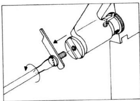
Technical line drawing of a mechanical assembly with no visible text or symbolsUnscrew the knife retaining screw and remove upper knife.
text_image
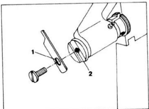
Technical diagram showing mechanical assembly with labeled parts 1 and 2To replace the upper knife, insert the retaining screw through cutout (1) of the knife. Screw it into threaded hole (2) of the knife holder. Tighten slightly and set the upper knife in the cutting position.
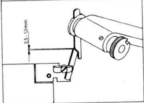
Turn the hand wheel counter-clockwise until the upper knife arm is in the lowest position. The front edge of the upper knife should be 0.5 to 1.0 mm lower in this position than the surface of the needle plate. Tighten the retaining screw securely.
text_image
0.5-1.0mm
natural_image
Illustration of a hand using a screwdriver to adjust a mechanical component (no text or symbols visible)Changing the light bulb:
Unplug the machine.
Remove the retaining screw from the light cover and swing cover to the left.
text_image
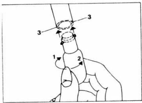
1 2 3 3Turn the bulb in direction (1) and remove it. Insert the new bulb with pins into slots (3). Push bulb up and turn it in direction (2).
Replace cover.
Caution: Use a 15 watt bulb only.
natural_image
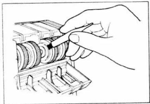
Hand inserting a component into a housing (no text or symbols visible)Cleaning thread tensions:
Flip the tension cover down.
natural_image
Hand operating a mechanical gear assembly (no text or symbols visible)Use the brush provided with the accessories to remove dust and lint from the discs.
Close the tension cover.
Oiling the machine:
Always clean the machine of lint and dust prior to oiling.
Use only one to two drops of good quality sewing machine oil at the places indicated (Fig. 1).
Since the bushings are oil impregnated, they need to be oiled only once or twice a month (Fig. 2).
natural_image
Technical line drawing of mechanical components with no visible text or symbols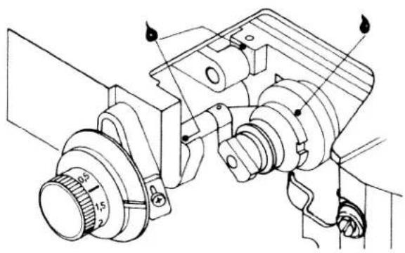
natural_image
Technical line drawing of a mechanical assembly with no visible text or symbolsiewing problems and solutions
This machine is easy to operate and there are no difficult adjustments to be made. Problems, similar to the ones described below, occur because of simple adjustment errors. They can easily be corrected by the solutions offered.
| Problem | Cause | Solution |
| Material is not fed correctly | Sewing foot pressure too weak | Turn sewing foot pressure screw clockwise to increase pressure. |
| Needle breakage | Needle bent or point damaged.Needle not correctly inserted.Material pulled | Insert new needle.Insert new needle correctly (see page 26).Do not pull or push material during sewing. |
| Thread breakage | Incorrectly threadedThread has caughtThread tension too tightNeedle not correctly insertedIncorrect needle used | Thread correctly (see pages 7-11).Check whether thread catches at the reel stand, etc.Regulate tension, (page 15, 16).Insert needle correctly (page 26).Use needle system DB x 1 (or 1738). |
| Skipped stitches | Needle bent or damagedNeedle not correctly insertedIncorrect needle usedIncorrectly threadedSewing foot pressure too weak | Insert new needle.Insert needle correctly (page 26).Use needle system DB x 1, or 1738Thread correctly (pages 7-11).Increase sewing foot pressure. |
| Incorrect stitch formation | Incorrect setting of thread tensions | Set thread tensions correctly (pages 15, 16). |
| Puckered seams | Thread tension too tightThread has caught due to incorrect threading | Reduce thread tension (especially for light materials)pages 15, 16.Thread correctly (pages 7-11). |
text_image
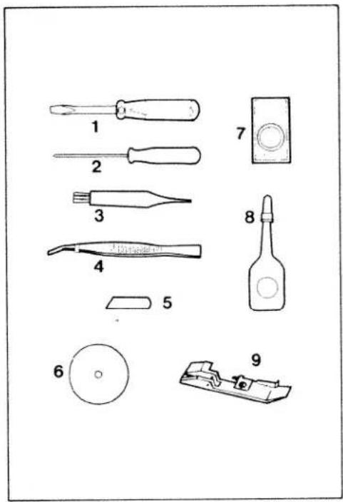
Diagram showing nine types of screwdriver tools and a bottle, labeled 1 through 9 with corresponding labels.Accessories
1 Screwdriver
2 Allen wrench
3 Lint brush
4 Tweezers
5 Lower knife
6 Thread unreeling disc
7 Needles
8 Oil
9 Rolled hem presser foot
Optional accessories
(not illustrated):
Blindhem foot
Elastic foot
Specifications
Highest sewing speed 1,300 stitches/min.
Overedge seam width 3.0-6.5 mm
Stitch length 1-5 mm
Sewing foot Snap-on
Lubrication Manual
Needle system DB x 1 or 1738 (size 9-14)
Dimensions 24 x 22 x 18.5 cm
Weight approx. 8.5 kg
(19 lbs.)
Subject to alterations in design No. 30 068 R 0288 engl.