hobbylock 788 - Sewing machine PFAFF - Free user manual and instructions
Find the device manual for free hobbylock 788 PFAFF in PDF.

User questions about hobbylock 788 PFAFF
0 question about this device. Answer the ones you know or ask your own.
Ask a new question about this device
Download the instructions for your Sewing machine in PDF format for free! Find your manual hobbylock 788 - PFAFF and take your electronic device back in hand. On this page are published all the documents necessary for the use of your device. hobbylock 788 by PFAFF.
USER MANUAL hobbylock 788 PFAFF
natural_image
Black-and-white illustration of a sewing machine with no visible text or symbolsInstruction manual
IMPORTANT SAFETY INSTRUCTIONS
- This sewing machine is designed and manufactured for HOUSEHOLD use only.
When using an electric appliance, basic safety precautions should always be followed, including the following:
Read all instructions before using this sewing machine.
DANGER
To reduce the risk of electric schock:
- The sewing machine should never be left unattended when plugged in. Always unplug this appliance from the electric outlet immediately after using and before cleaning.
- Always unplug before relamping. Replace bulb with same type rated 15 Watts.
- Do not reach for a sewing machine that has fallen into water. Unplug immediately.
- Do not place or store sewing machine where it can fall or be pulled into a tub or sink. Do not place in or drop into water or other liquid.
WARNING
To reduce the risk of burns, fire, electric schock, or injury to persons:
- Do not allow to be used as a toy. Close attention is necessary when this sewing machine is used by or near children.
- Use this sewing machine only for its intended use as described in this manual. Use only attachments recommended by the manufacturer as contained in this manual.
- Never operate this sewing machine if it has a damaged cord or plug, if it is not working properly, if it has been dropped or damaged, or dropped into water. Return the appliance to the nearest authorized dealer or service center for examination, repair, electrical or mechanical adjustment.
- Never operate the sewing machine with any air openings blocked. Keep ventilation openings of the sewing machine and foot controller free from the accumulation of lint, dust, and loose cloth.
- Never drop or insert any object into any opening.
- Do not use outdoors.
- Do not operate where aerosol (spray) products are being used or where oxygen is being administered.
- To disconnect, turn all controls to off ("O") position, then remove plug from outlet.
- Never operate on a soft surface such as a bed or couch where the air openings may be blocked.
- Do not unplug by pulling on cord. To unplug, grasp the plug, not the cord.
- Keep fingers away from all moving parts. Special care is required around the sewing machine needle.
- Always use the proper needle plate. The wrong plate can cause the needle to break.
- Do not use bent or blunt needles. Use needles recommended by the manufacturer only.
- Do not pull or push fabric while stitching. It may deflect the needle causing it to break.
- Switch the sewing machine off ("O") when making any adjustments in the needle area, such as threading needle, changing needle, threading bobbin, or changing presser foot, etc.
- Always unplug sewing machine from the electrical outlet when removing covers, lubricating, or when making any other user servicing adjustments mentioned in the instruction manual.
- Hold plug when rewinding into cord reel. Do not allow plug to whip when re-winding.
SAVE THESE INSTRUCTIONS
Contents
Controls of the sewing machine 2,3
Accessory box
Electrical connection
Master switch and sewing light.
Foot control
Notes on safety
How to handle the thread spool stand
Opening the looper cover and the swivel-type work support.
Threading guide wires 18 and 22.
Threading the right looper
Threading the left looper / threading slide . . . . . . . . . . . . . . . . . . . . . . . . . . . . . . . . . . . . . . . . . .
Threading the left and right needle
Needle threader . . . . . . . . . . . . . . . . . . . . . . . . . . . . . . . . . . . . . .
Thread reel change on threaded machine . . . . . . . . . . . . . . . . . . . . . . . . . . . .
Inserting the lint box 12
Seam allowance . . . . . . . . . . . . . . . . . . . . . . . . . . . . . . . . . . . . . . . . . . . . . . . 12
Sewing test 14
Points to observe during sewing
Thread cutter . . . . . . . . . . . . . . . . . . . . . . . . . . . . . . . . . . . . . . . . . . . . . .
Securing the seam . . . . . . . . . . . . . . . . . . . . . . . . . . . . . . . . . . . . . . . . . . . . .
Setting the standard thread tensions.
Possibilities requiring thread tension corrections.
3-thread overedge seam
Engaging and disengaging the converter (Hobbylock 788)
Thread tension adjustment for sewing with 1 needle and 2 threads . . . . .
Thread chart 20
Adjusting the stitch length
Adjusting the differential feed (Hobbylock 788) . . . . . . . . . . . . . . . . . . . . . . . . . . . . . . . . . . . . . .
Disengaging the upper knife.
Adjusting the seam width
Changing the sewing foot
Changing the light bulb 24
Cleaning the thread tensions
Rolled hem with 3 threads . . . . . . . . . . . . . . . . . . . . . . . . . . . . . . . . . . . . . . . . . . . . . . . . . . . . . . . . . . . . . . . . 26, 27
Rolled hem with 2 threads
Changing the needles . . . . . . . . . . . . . . . . . . . . . . . . . . . . . . .
Changing the knives
Changing the upper knife.
Changing the lower knife.
Upper knife arresting
Cleaning the knives.
Oiling the machine . . . . . . . . . . . . . . . . . . . . . . . . . . . . . . . . . . . . . . . . . . . .
Stitch selection table 34-35
Sewing problems and their removal . . . . . . . . . . . . . . . 40 - 4
Accessories
Thread spool net/thread unreeling disc . . . . . . . . . . . . . . . . . .
Mounting of the Converter
Special accessories.
Specifications / contents of the cardboard box . . . . . . . . . . . . .

text_image
18 19 17 36 1 38 39 15 14 12 13 2 7 6 5 4 3 16 10
text_image
24 42 25 37 26 43 27Controls of the sewing machine
1 Thread spool stand
2 Carrying handle
3 Left needle thread tension dial
4 Right needle thread tension dial
5. Right looper thread tension dial
6 Left looper thread tension dial
7 Thread tension cover
8 Lint box
9 Handwheel
10 Looper cover with recess
11 Upper knife
12 Swivel-type work support
13 Needle plate
14 Sewing foot
15 Needle holder
16 Sewing foot lifting lever
17 Thread spool holder
18 Color-coded thread guides
19 Telescopic thread guide bar
20 Machine socket
21 Master switch
22 Rear thread guide (4x)
23 Differential feed adjustment knob (Hobbylock 788)
24 Accessory box
25 Stitch length adjustment knob
26 Seam width adjustment knob
27 Rotary lever for upper knife disengagement
28 Foot control
29 Foot control plug for machine socket
30 Mains plug
31 Right looper
32 Left looper
33 Lower knife
34 Retaining screw of lower knife
35 Retaining screw of upper knife
36 Thread spool centering piece
37 Upper knife arresting screw
38 Lamp cover
39 Thread cutter
40 Looper threader
41 Converter
42 Needle threader
43 Tweezers

natural_image
Technical line drawing of a mechanical component with a base and mounting bracket (no text or symbols)
text_image
22 23 9 21 20
text_image
Technical diagram of a mechanical assembly with numbered components for identification
text_image
28 29
natural_image
Two-step line drawing showing hand operating a sewing machine with gear and handle (no text or symbols)Accessory box
Swing open work support 12 and pull out accessory box 24.
The accessory box can only be inserted in its compartment when held as shown in the illustration at left. The guide groove is up and the projection of the box faces the machine.

natural_image
Diagram of a computer interface showing a cable connector inserted into a socket with an arrow indicating the cable's direction (no text or symbols present)Electrical connection
Use this machine only on a flat surface or on a special machine table.
Connecting foot control 28: Insert plug 29 of the control in machine socket 20. Then connect mains plug 30 to a power source.
Caution: When the machine is not in use, always switch it off at master switch 21 and disconnect the plug from the power source. do not place any objects on the foot control.

natural_image
Two-panel line drawing showing a kitchen appliance with a control panel and a door, no text or symbols present.Switching the machine ON and OFF
Power and sewing light together are switched on and off with master switch 21.
Switching on:
Press switch. Machine and sewing light are switched on.
Switching off:
Press switch again. Machine and sewing light are switched off.

text_image
Technical diagram showing a hand pressing a device with directional arrows and a close-up of the device's internal control panel.Foot control
The speed of the Hobbylock is regulated as follows:
The more you press the foot control down, the faster the machine will sew.
Electronic foot control
Maximum speed can be pre-selected in two steps by the switch on the foot control.
Position ▶ = Half speed
Position ◀◀◀ = Full speed
Notes on safety
A) Owing to the up and down movement of the needles and the upper knife, the user must take sufficient care to avoid injury and observe the sewing area continuously while sewing.
B) When leaving the machine, changing parts or accessories, the machine must be disconnected from the power source.
C) The maximum approved wattage of the light bulb is 15 watt.
D) The drive belt must never be adjusted by anyone but an authorized Pfaff agent.

How to handle the thread spool stand
Pull thread spool stand 1 as far as it will go in the direction indicated by the arrow.
Fully extend telescopic thread guide bar 19. Slowly turn the two upper telescopic sections until you hear their detent balls snap in place.
After use fold up telescopic thread guide bar 19.
Push thread spool stand (with or without spools) up against the machine.

text_image
Technical diagram showing mechanical assembly steps with labeled components and directional arrowsOpening and closing looper cover and work support
Push looper cover 10 fully to the right, hold it, and swing it down.
To close the looper cover, push it up until it locks.
To open work support 12, push it in the direction indicated by the arrow. To close the work support, push it lightly until it locks.
Behind the looper cover converter 41 (Hobbylock 788) is illustrated with its slide settings for the respective stitch type. On the inside of the looper cover the individual threading paths are illustrated in colors.
Important!
While the looper cover or work support is open, power supply to the machine is interrupted.

natural_image
Technical line drawing of a mechanical device with multiple arms and levers (no text or symbols)Threading of guide wires 18 and 19
Place thread spools on thread spool stands. The machine must be threaded correctly. First pull the threads through guides 18 according to colors. Then lift carrying handle 2 and place the thread in rear guides 22. Set the thread tensions at N and thread the machine in the following sequence:
- right looper (yellow)
- left looper (red)
- right needle (green)
- left needle (blue)
Push carrying handle 2 down again.

text_image
Technical diagram of a sewing machine with numbered components for identificationThreading the right looper
The slide of converter 41 must be in its right position B (HL 788). Please refer to page 18.
Thread right looper 31 in sequence 1 to 9 and pull approximately 10 cm (4,) of thread through the looper eye (the thread path is marked red).
Important:
In order to obtain perfect sewing results, the thread must be pulled between the tension discs when threading the tensions.

text_image
Technical diagram of a mechanical assembly with numbered components for identification
natural_image
Technical line drawing of a sewing machine (no text or labels visible)Threading the left looper
Thread left looper 32 (yellow thread path) in sequence 1 to 6. From thread guide 6 pull the thread through looper eye 7.

text_image
Technical diagram of a mechanical assembly with numbered components, likely for repair or assembly instructions.Align the mark on handwheel 9 with the mark on the housing. Tauten the thread a little and place it in thread guide 8 by means of tweezers 43.

natural_image
Technical line drawing of a mechanical component with no visible text or symbols
text_image
Technical diagram showing numbered mechanical components with arrows indicating movement or assemblyThread guide 9 is threaded by means of looper threader 40.
- The mark on handwheel 9 must be aligned with the mark on the housing.
- Tauten the thread a little.
- Push the slide of the looper threader fully to the left, then pull lightly on the thread and allow the slide to return slowly. By this means the thread is placed in guide 9.
Note:
If the slide can not be moved the marks on the hand wheel and the housing are not correctly aligned.

text_image
Technical diagram of a sewing machine with numbered parts and labeled parts A, B, 1-6Threading the right needle
Threading of guide wires 18 and 22 is shown on page 7.
In the left-hand illustration the threading path is shown from green tension 1 up to right needle eye 6. Thread the needle from the front.
The use of needle threader 42 is described on the next page.
Threading the left needle
Threading of guide wires 18 and 22 is shown on page 7.
In the left-hand illustration the threading path is shown from blue tension 1 up to left needle eye 6. Thread the needle from the front.
The use of needle threader 42 is described on the next page.
is
n

text_image
Technical diagram of a mechanical assembly with labeled parts A and B, showing tool path and component alignment.
text_image
Technical diagram of a sewing machine needle with labeled parts A, B, C, and D
natural_image
Technical line drawing of a mechanical tool with a spring and pointer, no text or symbols presentNeedle threader
Lower the sewing foot by means of lifting lever 16.
Turn the hand wheel until right looper 31 is positioned right of the needle (see top of page 18). Place the thread in slot A of needle threader 42 and tauten it a little, holding the needle threader a little turned to the front. With the needle located between the two guide lugs B move the needle threader slowly downwards at the rear side of the needle until small hook C engages in the needle eye.
Hold the thread taut and place it in hook D; it will then automatically be placed in hook C, too.
Pull the needle threader to the rear, out of the needle eye, and the thread will be pulled through the eye.
Pull the thread completely through the needle eye.
Thread spool change on threaded machine
Cut the threads close to the thread spool. Place new thread spools on spool holders 17. Tie the threads still in the machine and the new threads to-gether. Pull the needle threads out of the needles. Now pull at the thread ends until the knots are about 15 cm past the last thread guide before the needles. Cut the knots off and pull the threads through the respective needle eyes. The looper threads can be pulled until past the looper eyes without interruption. Pull about 10 cm of thread through the looper eye.

natural_image
Line drawing of a sewing machine with no visible text or symbolsAfter threading the machine, push handle 2 down, and close work support 12 and looper cover 10.

natural_image
Line drawing of a hand operating a sewing machine (no text or symbols present)Inserting the lint box:
Insert the two tabs of lint box 8 downwards in the recess of looper cover 10. Then push the bottom of the box against the machine.
For removal of the lint box, use the reverse order.

natural_image
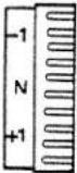
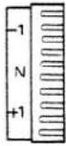
Technical line drawing of a sewing machine needle and foot (no text or symbols)Seam allowance
If the cutting is guided along below mark N on looper cover 10, a seam allowance of 16 mm must be taken into consideration when cutting the fabric.

natural_image
Technical line drawing of a mechanical assembly with a hand operating a lever (no text or symbols present)Sewing test
After threading, a sewing test should be made.
Raise sewing foot lever 16, as shown in the illustration.

natural_image
Line drawing of a sewing machine needle stitching fabric (no text or symbols)Hold the thread ends with your left hand while turning the hand wheel with your right hand in the direction indicated by the arrow on the wheel.
Hold the threads taut and lay them back under sewing foot 14. Make sure the threads interlock correctly during sewing (thread chain).

natural_image
Technical line drawing of a sewing machine needle and base (no text or symbols)Insert the test fabric up to upper knife 11 and lower sewing foot lever 16.

natural_image
Technical line drawing of a sewing machine needle stitching a fabric (no text or symbols)Points to observe during sewing
Sew the first stitches slowly. If the machine has been rethreaded, place the fabric under sewing foot 14 and push it up to the needle before starting to sew.
Since the fabric is fed automatically, do not pull or push the fabric. Use your hands for guiding only.

natural_image
Line drawing of a sewing machine needle stitching a seam, showing mechanical components and no text or symbolsThread cutter
In order to be able to use thread cutter 39 it is necessary to sew beyond the end of the seam. Draw the resulting thread chain through the thread cutter from the rear (see illustration below left).

natural_image
Line drawing of a sewing machine needle stitching a thread, with no text or symbols presentSecuring the seam:
Knot the thread chain. For knit fabrics, a crochet needle can be used to pull the thread chain into the seam.
Or:
Sew about 5 cm (2") beyond the end of seam. Turn the workpiece around and sew a few stitches over the seam just sewn without cutting the thread chain.

text_image
Face side Right looper thread Left looper thread Right needle thread Left needle thread Reverse sideSetting the standard thread tension N
Optimum seam appearance depends on the type of fabric used, on the thread size, and on the thread tension setting. Set the N on the thread tension dials opposite the round colored mark on thread tension cover 7 (see illustration below).
Make the correct adjustment after examination of the interlocking of threads (the illustration on the left shows a correct four-thread overedge seam).
Page 16 lists examples for correction of the individual thread tensions.
Recommendation!
Allocation of the individual threads in a seam to their respective looper- and needle thread tensions will be easier if, as an exercise, you thread the tensions with differently colored threads (e.g. thread color = tension color).

natural_image
Technical line drawing of a mechanical device with multiple ports and a top-mounted component (no text or symbols)
text_image
Face side Reverse side APossibilities requiring thread tension corrections
When the thread tension is turned in (+) direction, the tension is increased. When turned in (−) direction it is decreased.
The left needle thread A is too loose (blue thread tension).

text_image
Face side Reverse side BThe right needle thread B is too loose (green thread tension).

text_image
Face side D C Reverse side-
The right looper thread C is too tight (red thread tension).
-
The left looper thread D is too loose (yellow thread tension).
-
Both tensions must be corrected.

text_image
Face side Reverse side D C-
The left looper thread D is too tight (yellow thread tension).
-
The right looper thread C is too loose (red thread tension).
-
Both tensions must be corrected.
| 3-thread overedge seam: Threading of the right and left looper is described on pages 8 and 9. The slide of converter 41 must be set at its right position B (see p. 18). |
| The 3-thread overedge seam is sewn with two looper threads and one needle thread.Seam width adjustments at adjustment knob 26 (3 to 5 mm) only refer to the right needle.When the left needle is used, the set value is increased by 2.2 mm (seam width 5.2 to 7.2 mm). |
| 3-thread overedge seam | |
| Left needle | Right needle |
 |  |
| Standard seam width N | Standard seam width N |
 |  |
| Max. seam width 7.2 mm | Max. seam width 5 mm |

natural_image
Technical line drawing of a mechanical device with a pencil and triangular component (no text or symbols)Engaging the converter (HL 788)
For the Hobbylock 787 the converter is available as a special accessory part (see p. 42 and 46).
Turn the hand wheel until right looper 31 is positioned right of the needle.
For sewing with converter 41 the right looper thread must be cut off and pulled out of the looper eye.

natural_image
Technical line drawing of a mechanical assembly or clamp mechanism (no text or symbols)All seams sewn with converter 41 are only sewn with left looper 32 and with one or two needle threads.

natural_image
Technical line drawing of a mechanical device with an arrow indicating motion (no text or symbols)The left looper thread placed over right looper 31 must be pulled over the point of the right looper in the direction of the arrow, as shown in the left-hand illustration.

text_image
A A ←→ BPush the slide of converter 41 to the left until the triangular symbols are aligned with each other. As you do so the point of the slide must engage in the eye of the looper, see Fig. A. Converter engaged = position A Converter disengages = position B
Disengaging the converter
Turn hand wheel 9 slowly until the left looper thread drops from the point of right looper 31. Disengage the converter in this position (position B). For threading the right looper, see p. 8.
r is
er
ht ul-
t n
| 2-thread overedge seam | |
| Left needle | Right needle |
| Standard seam width N | Standard seam width N |
 |  |
| Adjustable range 5.2 to 7.2 mm | Adjustable range 3 to 5 mm |

text_image
Face side Reverse side A BThe left-hand illustration shows the 2-thread overedge seam with correctly set thread tensions.

text_image
Face side A B Reverse sidePossible correction requirements:
- Looper thread A is too loose (yellow thread tension).
- Needle thread B is too tight (blue or green thread tension).
- Both tensions have to be corrected.

text_image
Face side A B Reverse side- Looper thread A is too tight (yellow thread tension).
- Needle thread B is too loose (blue or green thread tension).
- Both tensions have to be corrected.
| Thread chart for 2-, 3-, 4-thread overedge seam | ||
| Material | Thread | Stitch length |
| Light materials:Organdy, light-knitfabric, Taffeta, silk,lining materials | Cotton No. 80-100Silk No. 80-100Synthetic thread No. 70-140 | 2.0 to 4.0 mm |
| Medium-heavymaterials:Cotton, tricot,linen, dress materials | Cotton No. 60-100Silk No. 50-100Synthetic thread No. 70-140 | 2.0 to 4.0 mm |
| Heavy materials:Tweed, suit materials,denim, heavy cloth | Cotton No. 40- 60Silk No. 40- 60Synthetic thread No. 70-140 | 2.0 to 5.0 mm (787)2.0 to 4.0 mm (788) |
| Knit fabrics: | Cotton No. 40-60Silk No. 40-60Synthetic thread No. 70-140 | 2.0 to 5.0 mm (787)2.0 to 4.0 mm (788) |
| Rolled hem with2 or 3 threads(bulk thread) | Polyester thread No. 120-140Mercerized thread | 1.0 to 2.0 mm |

natural_image
Technical line drawings of a mechanical device with internal components and mounting brackets (no text or symbols)| Setting the stitch length on the Hobbylock 788 with differential feedOpen work support 12.Hold hand wheel 9 fast and set stitch-length adjustment knob 25 at the stitch length desired between 1 and 4 mm.Standard setting N is 3 mm. |
| Setting the stitch length on the Hobbylock 787 without differential feedOpen work support 12.Hold hand wheel 9 fast and set stitch-length adjustment knob 25 at the stitch length desired between 1 and 5 mm.Standard setting N is 3 mm. |

natural_image
Line drawing of a sewing machine with a hand operating the button (no text or symbols)Adjusting the differential feed on the Hobbylock 788
The differential feed prevents inter-ply shift. It consists of two feed dogs, arranged one behind the other, which both pick up and move the workpiece at the same time.
The feed amount of either feed dog can be set separately. It is possible to have the workpiece moved more by the front feed dog than by the rear one and vice versa. Owing to that very good sewing results are accomplished. Set the differential feed according to the material you wish to process (see table on page 22). The following settings are possible at button 23:
Setting 0.5 = Short stroke of front feed dog, long stroke of rear feed dog
Setting N = Same stroke of both feed dogs
Setting 1.5 = Long stroke of front to 2 feed dog, short stroke of rear feed dog
The differential feed can be set infinitely from 0.5 to 2, also during sewing.
Note:
The following variants can be employed to obtain fashionable effects on garments:
The gather effect is obtained at a differential feed setting of 1.5 - 2 when light fabrics are processed.
The wave effect is obtained at a differential feed setting of 0.5 when medium to heavy elastic fabrics are processed.
This table indicates possible settings of the differential feed of the Hobbylock 788. In order to make sure about the setting required for the fabric you wish to process, a sewing test has to be made. – The differential feed can also be set during sewing.
| Setting of dif-ferential feed | Illustration | Correct seam | Fabric |
| 0.5 to N | 1 | a | Nylon, tricot, lining fabrics, satin, poplin, and silk |
| N | 2 | c | Light cotton, jeans (normal fabrics) |
| 1.5 | 3 | d | Jersey, medium cotton, nicki fabrics, light knittings |
| 1.5 to 2 | 4 | f | Heavy knitwear, very elastic fabrics, rib stitch goods |

natural_image
Two grayscale textured surfaces labeled 'a' and 'b', showing no text or symbols within the patterns.Fig. 1

natural_image
Close-up of a textured fabric surface with a dark horizontal band at the bottom (no visible text or symbols)Fig. 2

natural_image
Two grayscale scientific images labeled 'd' and 'e', showing textured surfaces with no visible text or symbols.Fig. 3

natural_image
Two textured fabric strips labeled 1 and 9, showing different surface textures (no text or symbols)Fig. 4

natural_image
Technical line drawing of a mechanical assembly with no visible text or symbolsDisengaging the upper knife
Remove lint box 8. Open work support 12 and looper cover 10. If necessary, loosen upper knife arresting screw 37.
Push rotary lever 27 of the axial upper knife guide fully to the right, hold it, and turn it forwards until the pin engages in the hole of the knife. Now the upper knife is disengaged.

natural_image
Line drawing of a hand operating a sewing machine tool (no text or symbols visible)Adjusting the seam width
The standard seam width setting is marked with N (3.5 mm).
Disengage upper knife 11 according to the above description.
The desired seam width is set with adjusting knob 26. The scale on the seam-width adjustment knob ranges from 3 to 5 mm.
Set the upper knife at its basic position again and close the looper cover.
When sewing thick materials, tighten screw 37 of the upper knife arresting system securely (see p. 32).
Sew a test seam.
Note:
The seam width adjustments made at adjustment knob 26 (3 to 5 mm) only refer to the right needle. When the left needle is used the value set is increased by 2.2 mm (seam width 5.2 to 7.2 mm).

text_image
Technical diagram showing two views of a sewing machine's foot and side view with labeled parts F, H, and G.Changing the sewing foot
Raise sewing foot lifting lever 16.
Disengage the sewing foot by pressing lever F.
Engaging the sewing foot:
Place the sewing foot under the sewing foot holder so that when you lower the sewing foot lifting lever, crosspiece G of the foot engages in groove H of the sewing foot holder.

natural_image
Technical line drawing showing two views of a sewing machine with hands operating the component (no text or symbols present)Changing the light bulb:
Pull out the mains plug.
Loosen lamp cover retaining screw 38.
Open the lamp cover.
Behind it, the light bulb of the sewing light is situated.
Removing the light bulb:
Push the light bulb upwards and turn it fully to the left.
Inserting the light bulb:
Insert the new bulb (15 watt max.) with the pins in the slots, push it up, and turn it fully to the right.
Close and fasten lamp cover.

Cleaning the thread tensions:
At the points indicated, press thread tension cover 7 in the direction of the arrows, thus loosening the cover, then remove it towards the front.
Set the 4 thread tensions at -5.
Use the cleaning brush (accessories) to remove dust and lint from between the tension discs of the 4 tensions.
Reset all thread tensions to N, or to the values set before cleaning.
Press the individual tabs of the thread tension cover in the direction indicated by the arrows, until the tabs audibly snap in place.
Then press against the two bottom corners of the cover in the direction indicated by the arrows in order to ensure proper engagement of the tension cover.

text_image
Face side Reverse side 1Fold-over 3-thread rolled hem sewn with polyester thread 120-140.
A rolled hem is used for light, delicate fabrics and is an attractive finish for open edges. Without any effort you can sew professional rolled hems on neck scarves, shawls and valances.
This rolled hem is sewn with three threads (see page 27).

text_image
Face side Reverse side 23-thread rolled hem
Rolled hem with polyester thread
Preparation of the sewing machine:
Needle: remove left needle / insert right needle
Sewing foot: engage rolled-hem foot „R“
Seam width: from 3.0 to 4.0 mm (depending on material)
Stitch length: from 1.0 to 2.0 mm (short stitch length)
Thread: polyester thread 120-140 for green, red and yellow thread tensions
Threading path:
- right looper, red path polyester thread
- left looper, yellow path polyester thread
- needle thread, green path polyester thread
For threading of needle and loopers, see pages 7 to 11.
| Tension setting: | fold-over 3-thread hem, Fig. 1 | 3-thread hem, Fig. 2 |
| Red thread tension, right looper | approx. „N” | approx. +5 |
| Yellow thread tension, left looper | +5 | approx. „N” to -1 |
| Green thread tension, needle thread approx. „N” | approx. „N” to +1 | |
Depending on material and thread, the respective thread tension must be set higher or lower.
Rolled hem, sewn with bulk thread:
This hem requires three threads, one bulk thread and two polyester threads 120 - 140.
Preparation of the machine, as described above.
Thread: bulk thread - red tension
polyester thread 120-140 for green and yellow tensions
Threading path:
- right looper, red path bulk thread
- left looper, yellow path polyester thread 120-140
- needle thread, green path polyester thread 120-140
For threading of needle and loopers, see pages 7 to 11.
Tension setting: fold-over 3-thread 3-thread hem, hem, Fig. 1 Fig. 2
Red thread tension, right looper approx. "N" to -3
Yellow thread tension, left looper approx. +5
Green thread tension., needle thread approx. "N"
approx. „N“ to +5
approx. „N“
approx. „N“
Note:
Rolled hems can also be sewn with two bulk threads and one polyester thread. The bulk threads must then be threaded in the left and right looper.
Depending on material and thread, the respective thread tension must be set higher or lower.
Hobbylock 788
2-thread rolled hem sewn with converter 41
(for this purpose the slide must be in position A (see p. 18).
Needle: insert right needle
Sewing foot: rolled-hem sewing foot
Seam width: N (3.5 mm)
Stitch length: 1.0 to 2.0 mm
For the Hobbylock 787 the converter is available as special accessory part (see p. 42 and 46).

text_image
top side under side2-thread rolled hem
A 2-thread rolled hem requires less thread and the seam has a finer look.

text_image
top side under sideFold-over 2-thread rolled hem

natural_image
Technical line drawing showing a hand operating a sewing machine with two separate views of the same tool (no text or symbols present)Changing the needles
Pull out the mains plug. Lower the sewing foot. Turn the hand wheel in the direction of the arrow until the needle bar is at its highest position.
Hold the needle with the tweezers, loosen screw A or B with the small screwdriver, and pull the needle downwards, out of the needle holder.
Inserting the needle
The needle has to be inserted with the flat side of its shank facing rear.
Use the tweezers to push the needle fully up in the needle holder, hold it there, and tighten the respective needle set screw.
Notes:
The following needles are used on these machines:
System 130/705 H (75-90)
Although the correct needle size depends on the material and the thread size used, we recommend needle size 75-90.
An incorrectly inserted needle will cause thread breakage and skipped stitches.

natural_image
Technical line drawing of a mechanical assembly with no visible text or symbolsChanging the knives
The top and bottom knives are available as spare parts.
Pull out the mains plug.
Change upper knife 11, see page 30.
Change lower knife 33, see page 31.

text_image
Technical diagram showing mechanical assembly steps with dimension annotation '0.5 - 1.0 mm'| Changing the upper knife:Pull out the mains plug!Unscrew knife retaining screw 35 and remove upper knife 11.Disengage the upper knife,see page 23. |
| Insert the new upper knife and tighten its retaining screw securely. Reset upper knife to its cutting position. |
| Set upper knife with knife guide 27 up (cutting position). Turn the handwheel until the upper knife is at its lowest position.In this position, the front edge of the upper knife must be 0.5 to 1 mm below the cutting edge of the lower knife. |

| Changing the lower knifePull out the mains plug!Disengage the upper knife (see p. 23).Remove retaining screw 34 of lower knife 33.Turn seam width adjustment knob 26 at position 3 (smallest seam width). |
| Hold the new lower knife in such a way that the pin extends into the front hole of the lower knife. Then screw down retaining screw 34 together with the pressure tab. |
| Align the cutting edge of the lower knife so that it is flush with the needle plate surface.Before tightening the retaining screw, align the pressure tab. Reset the upper knife to cutting position.Set the required seam width at adjustment knob 26. |

natural_image
Technical line drawing of a mechanical assembly with hands operating a tool (no text or symbols present)Upper knife arresting
Sewing very thick fabrics and workpieces with different ply thicknesses:
On this machine, all kinds of fabric from extremely thin to extremely thick can be processed. When sewing extremely thick fabrics or workpieces with different thicknesses, the screw of the upper knife must be tightened, as shown in the illustration.
By tightening screw 37, the upper knife is arrested axially.
Note:
When sewing thin or medium fabrics, screw 37 of the upper knife arresting system must be loosened by about 2 turns, so that the upper knife can move axially.

natural_image
Technical line drawing of a mechanical assembly with no visible text or symbolsCleaning the knives
Disengage the upper knife (see top of p. 23).
Use the lint brush (accessories) to remove lint from upper and lower knife.
Oiling the machine:
Every time before you take the machine into operation, you should apply a little oil to the places indicated. The bushings and other important moving parts are made of special material and need to be oiled only once or twice a month. One to two drops of PFAFF sewing machine oil are sufficient.

natural_image
Technical line drawing of a mechanical assembly with no visible text or symbols
natural_image
Technical line drawing of a mechanical assembly with mounting holes and structural brackets (no text or symbols)
natural_image
Technical line drawing of a mechanical assembly with no visible text or symbolsStitch selection table
The values set for thread tension, stitch length, needle size, and the differential feed setting (788) are only basic settings that have to be varied according to the application, i.e. to the type of fabric, the fabric thickness, and the thread used.
The sewing foot must be selected according to the seam width (see ill. at right).
The differential feed setting depends on the type of fabric sewn (see p. 22).
For all 2-thread seams and for the 2-needle 3-thread overedge closing seam the slide of converter 41 (HL 788) must be set at position A.
For HL 787 the converter is available as a special accessory part (see p. 42 and 46).
| Stitch type | Fabric(see tableon p. 20) | Needle thread tension | Looper thread tension | Needle-System130/705 H15 x 1 H | |||
 | blue | green | red | yellow | A | B | |
| light | -2 | +2 | Size9014 | ||||
| medium | -2 | +2 | |||||
| heavy | N | +3 | |||||
2-thread overede seam, wide (2-thread flatlock | light | -5 | +1 | Size9014 | |||
| medium | -5 | +1 | |||||
| heavy | -4 | +2 | |||||
2-thread serging seam without edge thread | light | +2 | N | Size9014 | |||
| medium | +2 | N | |||||
| heavy | +3 | N | |||||
2-thread serging seam without edge thread | light | -2 | -1 | Size9014 | |||
| medium | -2 | -1 | |||||
| heavy | -1 | -1 | |||||
Sewing foot N3 for seam widths of 3 to 4.5 mm
Sewing foot N for seam widths of 4 to 6 mm
Sewing foot N2 for seam widths of 5.5 to 7.2 mm
Rolled hem sewing foot R


| Thread spool | Sewing foot | Stitch length | Differential feed setting on HL 788 | Slide position of converter | ||||
 |  | Fig. HL 788 |  |  | ||||
| A | B | |||||||
| N or N 3 (see tops of p. 35) | N | N | ● | |||||
| N or N 2 (see top of p. 35) | N | N | ● | |||||
| N or N 3 (see top of p. 35) | N | N | ● | |||||
| N or N 2 (see top of p. 35) | N | N | ● | |||||
| Stitch type | Fabric(see tableon p. 20) | Needle thread tension | Looper thread tension | Needle-System130/705 H15 x 1 H | |||
 blue blue | 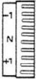 green green |  red red | 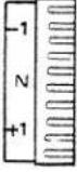 yellow yellow |  | |||
| A | B | ||||||
| 2-thread rolled hem (narrow) | light | -2 | -1 to N | Size7511 | |||
| medium | -2 | -1 to N | |||||
| Folded 2-thread rolled hem | light | N | -1 to N | Size7511 | |||
| medium | N | -1 to N | |||||
| 3-thread overedge seam (narrow) | light | -1 | N | N | Size9014 | ||
| medium | N | N | N | ||||
| heavy | +1 | N | N | ||||
| 3-thread overedge seam (wide) | light | -4 | -2 | -1 | Size9014 | ||
| medium | -3 | -2 | -1 | ||||
| heavy | N | N | N | ||||
| 3-thread serging seam without edge thread(narrow) | light | N | -3 | +2 | Size9014 | ||
| medium | N | -3 | +2 | ||||
| heavy | N | -3 | +2 | ||||
| 3-thread serging seam without edge thread(wide) | light | -3 | -4 | +2 | Size9014 | ||
| medium | -2 | -4 | +2 | ||||
| heavy | N | -4 | +4 | ||||
| Thread spool | Sewing foot | Stitch length | Differential feed setting on HL 788 | Slide position of converter | ||||
 |  | Fig. HL 788 |  |  | ||||
| A | B | |||||||
| [A637] | [08HY] | R(see top of p. 35) | 1 to 1.5 | N | ● | |||
 | [803K] | R(see top of p. 35) | 1 to 1.5 | N | ● | |||
| [C8KO] |  | N or N 3(see top of p. 35) | N | N | ● | |||
| [22VT] |  |  |  | N or N 2(see top of p. 35) | N | N | ● | |
| [04HW] | [307Y] | N or N 3(see top of p. 35) | N | N | ● | |||
| [7223] |  | N or N 2(see top of p. 35) | N | N | ● | |||
| Stitch type | Fabric(see tableon p. 20) | Needle thread tension | Looper thread tension | Needle-System130/705 H15 x 1 H | |||
 blue blue | 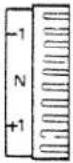 green green | 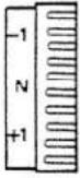 red red | 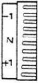 yellow yellow |  | |||
| A | B | ||||||
| Decorative 3-threadserging seam (3-threadflatlock seam) | light | -2 | +2 | +4 | Size9014 | ||
| medium | -2 | +2 | +4 | ||||
| heavy | -2 | +2 | +4 | ||||
| Decorative 3-threadserging seam wide(3thread flatlock seam) | light | -5 | +1 | +3 | Size9014 | ||
| medium | -5 | +1 | +3 | ||||
| heavy | -5 | +1 | +5 | ||||
| 3-thread rolledhem (narrow) | light | -1 | +1 | N | Size7511 | ||
| medium | N | +1 | N | ||||
| Folded 3-threadrolled hem | light | -1 | +1 | N | Size7511 | ||
| medium | N | N | +3 to +5 | ||||
| 2-needle 3-threadoveredge closing seamwithout edge thread | light | -3 | -2 | -2 | Size9014 | Size9014 | |
| medium | -2 | -1 | -2 | ||||
| heavy | N | N | -1 | ||||
| 4-thread overedgeseam | light | -3 | -2 | -2 | -1 | Size9014 | Size9014 |
| medium | -2 | -1 | -2 | -1 | |||
| heavy | N | N | N | N | |||
| Thread spool | Sewing foot | Stitch length | Differential feed setting on HL 788 | Slide position of converter | ||||
 |  | Fig. HL 788 |  |  | ||||
| A | B | |||||||
| N or N 3 (see top of p. 35) | N | N | ● | |||||
| N or N 2 (see top of p. 35) | N | N | ● | |||||
| R (see top of p. 35) | 1 to 1.5 | N | ● | |||||
| R (see top of p. 35) | 1 to 1.5 | N | ● | |||||
| N or N 2 (see top of p. 35) | N | N | ● | |||||
| N or N 2 (see top of p. 35) | N | N | ● | |||||
Sewing problems and solutions
These machines have been developed for easy operation, and there are no difficult adjustments to be made. Sewing problems of the kind described below may occur due to minor adjustment-and operation errors. They can easily be corrected by following the instructions below.
| Problem | Cause | Solution |
| Needle breakage | Needle bent or point damagedNeedle not fully insertedMaterial pulled | Insert new needleInsert new needle correctly (see p. 29)Do not pull material during sewing |
| Thread breakage | Incorrectly threadedThread has caughtThread tension too tightNeedle not fully insertedIncorrect needle used | Thread correctly (see pp. 7-11)Check whether thread catches at the reel stand, etc.Regulate tension, (pp. 15-16)Insert needle correctly (p. 29)Use needle system 130/705 H |
| Skipped stitches | Needle bent or point damagedNeedle not fully insertedIncorrect needle usedIncorrectly threaded | Insert new needleInsert needle correctly (p. 29)Use needle system 130/705 HThread correctly (pp. 7-11) |
| Incorrect stitch corformation | Incorrect setting of thread tensions | Set thread tensions rectly (pp. 15-16) |
| The 3- or 4-thread overedge seam has an irregular appearance, and the right looper thread has not interlocked in the seam | The converter is in its left position A (see p. 18) | Set converter in its right position B (see p. 18) |
| Machine does not run although master switch is on | Power supply interrupted looper cover 10 or work support 12 (see p. 7) | Close looper cover 10 or work support 12 (see p. 7) |
| Fabric not neatly trimmed | Sewing lint between upper and lower knifeUpper knife blunt | Clean knives (see p. 32)Exchange upper knife (see p. 30) |
| Puckered seams | Thread tension too tightIncorrect setting of differential feedThread has caught due to incorrect threading | Reduce thread tension (especially for light materials) (pp. 15 – 16)Re-adjust differential feedThread correctly (pp. 7 – 11) |
| Puckered seams | Inadequate sewing foot used for seam width sewn | Insert sewing foot adequate for the seam width (see top of p. 35) |
| Edge thread too loose | Inadequate sewing foot used for seam width sewn | Insert sewing foot adequate for the seam width (see top of p. 35) |

text_image
Illustration of 13 different types of tools and components, numbered 1 to 13, including screwdriver, tool holder, and plastic clip.Accessories
1 Screwdriver (big)
2 Screwdriver (small)
3 Lint brush
4 Tweezers
5 Upper knife
6 Thread unreeling disc
7 Needles
8 Sewing machine oil
9 Rolled hem sewing foot (R)
10 Sewing foot N2
11 Sewing foot N3
12 Thread spool net
13 Needle threader
Description of special accessories
on pp. 43-50
Elastic tape sewing foot
Part No. 29-924 993-80/000
Taping foot
Part No. 29-924 993-82/000
Blindstitch sewing foot
Part No. 29-924 993-81/000
Bead sewing foot
Part No. 29-924 993-83/000
Cording foot
Part No. 29-924 993-70/900
Shirring foot
Part No. 29-924 993-70/901
Lace sewing foot
Part No. 29-924 997-70/906
Gimp thread sewing foot
Part No. 29-924 924-70/908
Thread spool support
Part No. 29-924 997-70/936
Converter (HL 787)
(see p. 46)
Part No. 29-924 997-70/937

text_image
A B CThread spool net
Very useful for synthetic threads which tend to become loose, unravel and slip down (Fig. A).
Thread unreeling disc
The thread unreeling disc shown as item 6 of the accessories is used for smaller thread spools.
Remove thread spool centering piece 36 from the thread reel pin.
Put the thread spool on the thread reel pin and place the thread unreeling disc on top of it, with rounded-off section C facing down, as shown in Fig. B.

text_image
Technical diagram of a sewing machine with labeled parts and a close-up of fabric textureBlindstitch sewing foot
Preparing the machine
Differential
feed setting: set at N
(Hobbylock 788)
Needle: insert the right needle Sewing foot: insert blindstitch foot Stitch width: "N" Stitch length: longest stitch length Thread tension: "N" (red, yellow, blue)
The hem is trimmed, serged and sewn in one operation.
Before sewing, cut hem part - 3 - in by 2 cm.
This avoids shifting of the hem.
Place the prepared hem under the sewing foot so that folded hem part -3- is under edge guide -2-. Crease line -4- of the outer fabric must run along the edge of guide -2-.
Regulating the penetration of the needle in the outer fabric
Loosen adjusting screw -1 - and adjust edge guide -2 - so that only one thread of the outer fabric is caught by the needle.

text_image
fabric beads 1-1.5 mm Fig. 1 2 1 Fig. 2Bead sewing foot (Fig. 1)
This special sewing foot is for sewing on beads, sequins, strass bands, lead- and ordinary cords. These operations are carried out with one needle.
- Set differential feed at N (Hobbylock 788)
- Insert bead sewing foot
- For small beads use the right needle
For large beads use the left needle (787, 788) - Push the bead tape through guides 1 and 2 to the end of the foot (Fig. 1).
- For all seam width settings it is possible to work with or without upper knife;
guide the fabric along the right-hand sewing foot edge. - Caution: only work with the upper knife at settings from N to 5.
- Stitch length: 3 to 4 mm
- Ascertain correct thread tension by making a test seam (N = standard setting).
Note: If the bead tape is sewn onto the fabric edge, the left needle must be used (disengage upper knife).
Thread tension: needle = -3 to -5
right looper = -1 to -3
left looper = +2 to +3
The needle should penetrate at about 1 to 1.5 mm from the fabric edge (see Fig. 2).

text_image
Technical diagram of a mechanical device with numbered components and directional arrow
natural_image
Close-up of a textured fabric or material surface with layered patterns and a dark corner (no visible text or symbols)Elastic tape sewing foot
This special sewing foot is for sewing on an elastic tape; in the same operation the fabric is trimmed and serged, and also gathered by the contracting elastic tape.
Preparing the machine
Differential
feed setting: set at N (Hobbylock 788) Needles: use 1 or 2 needles, depending on tape width
Sewing foot: insert elastic taping foot
Thread tension: „N“
Stitch width: 4 to 4.5
Stitch length: approx. 4
Inserting the elastic tape:
Loosen screw -2 - so that brake -1 - at opening -4 - is opened by 1.5 to 2 mm. Place in elastic tape -3 - and pass it back under the foot. Tighten brake -1 - with screw -2 - again. The more screw -2 - is turned, the stronger the pressure of brake -1 - on the elastic tape and thus the greater the gather effect.
Note:
When the sewing foot is raised, the elastic tape should be pulled through brake - 1 - slightly braked.

text_image
Technical diagram of a mechanical device with labeled parts and a close-up of a textured surface showing layered structure.Taping foot
This special sewing foot is for sewing on tapes. On stretch materials (knitwear) the seams are prevented from stretching when a tape is sewn on.
Preparing the machine
Differential
feed setting:
set at N
(Hobbylock 788)
Needles:
use 1 or 2 needles,
depending on tape
width
Stitch width:
3 to 5 mm (adjustable
for a tape width from
4 to 9 mm)
Stitch length:
„N“
Thread tension:
“N”
Inserting the tape:
- Set needle at highest position.
- Disengage upper knife.
- Raise sewing foot and place tape in guides -1- from right.
- Push tape to right stop with slide -2-.
- Adjust location of tape in relation to needle by turning adjusting screw -3-
- Place fabric in and carry out a sewing test.

text_image
Technical diagram showing mechanical assembly with labeled parts B and E, likely from an engineering or manufacturing context.Mounting of the Converter
Turn hand wheel 9 until right looper 31 is right of the needle.
Set the converter at position B, place it on the looper drive shaft as indicated by the arrow in the illustration, and press it firmly downwards until it audibly snaps over looper stud E.
For operation, see page 18.

natural_image
Technical diagram of a sewing machine with a vertical seam and fabric pattern, no visible text or symbolsCording foot
This special sewing foot is used for sewing a cording tape between two fabric plies in one operation.
Preparing the machine
Differential
feed setting: set at N
(Hobbylock 788)
Needles: two needles or left one
Sewing foot: engage cording foot
Upper knife: engaged
Thread tension: „N“
Stitch width: 3 to 5
Stitch length: „N“
Inserting the fabric plies
- Raise the sewing foot
- Set needle at its highest position
- Place bottom ply, cording tape and top ply (face side to face side) together under the sewing foot flush, and insert up to the upper knife.
- The cording (piping) must be placed in guide 1.
- Lower the sewing foot.
- Make a sewing test.

natural_image
Technical line drawing of a mechanical component with a spool and base (no text or symbols)Thread spool support
When big thread spools are used (5,000 to 10,000 meters) it is recommendable to place them on thread spool supports.
To prepare the machine, place centering pieces 36 upside down on thread spool holders 17, as shown in the illustration at left.
When synthetic threads are used, the thread spool supports prevent down-slipping thread windings from becoming entangled, thus guaranteeing perfect unreeling of the thread.

text_image
Technical diagram of a sewing machine with numbered parts labeled 1 to 4
natural_image
Microscopic view of layered material with scattered dark particles (no text or symbols)Shirring foot (Hobbylock 788)
This special sewing foot is used for joining two pieces of fabric and shirring the bottom ply in one operation.
Preparing the machine
Differential
feed setting:
set at N
(Hobbylock 788)
Needles:
Sewing foot:
two or one
Upper knife:
engage shirring foot
Needle thread
tension:
engaged
Stitch length:
+3 to +5
Inserting the fabric plies
- Raise the sewing foot.
- Set needle at its highest position.
- Place bottom fabric ply 1 between needle plate and shirring foot, and insert up to upper knife.
- Place top fabric ply 2 in opening 3 lush with the bottom ply (face side to face side), and insert up to stop 4.
- Lower the sewing foot.
- Make a sewing test.

natural_image
Technical line drawing of a sewing machine with labeled parts (no text or symbols present)
natural_image
Close-up of a textured surface with a dark central region and a light gray vertical band on the right (no text or symbols)
natural_image
Close-up of a textured fabric with a vertical seam and a side split, no visible text or symbolsGimp thread sewing foot
This special sewing foot is used for sewing in gimp threads (cords, synthetic threads) up to a thickness of 1.0 mm. By this means a wavy, i.e. more firm hem finish is achieved (e.g. on wedding dresses, curtains, etc.).
Preparing the machine
Differential
feed setting:
set at N
(Hobbylock 788)
Needle:
insert right needle
(HL 787, 788)
Stitch width:
3 to 4 mm
Stitch length:
1.0 to 1.5 mm
Thread tension
(cf. section
right looper
approx. N
„Rolled hem):
left looper + 5
needle thread
approx. N
Inserting the gimp thread
- Raise sewing foot and set needle up.
- Engage upper knife.
- Place fabric under the sewing foot.
- Thread gimp thread (cord) through hole 1, then place it in guide 2 of the sewing foot shoe.
- Sew a test seam.
Specifications:
Maximum sewing speed . . . . . . . . . . 1,300 stitches/min.
Seam width 3 - 7.2 mm
Stitch length 1 - 4 mm (HL 788) 1 - 5 mm (HL 787)
Sewing foot . . . . . . . . . . . . . . . . . . . Hinged
Lubrication. Manual
Sewing foot height . . . . . . . . . . . . . 5 mm
Needle system 130/705 H or 15 x TH
Needle size 75-90 or 11-14
Number of threads 788/787 2,3,4/3,4
Dimensions 315 x 280 x 330 mm
Weight 788 / 787 . . . . . . . . . . . . . 8.5 kg / 8.0 kg
Contents of cardboard box
1 machine with motor
1 foot control
1 instruction manual/guarantee certificate
1 lint box
1 machine cover