hobbylock 783 - Sewing machine PFAFF - Free user manual and instructions
Find the device manual for free hobbylock 783 PFAFF in PDF.

User questions about hobbylock 783 PFAFF
0 question about this device. Answer the ones you know or ask your own.
Ask a new question about this device
Download the instructions for your Sewing machine in PDF format for free! Find your manual hobbylock 783 - PFAFF and take your electronic device back in hand. On this page are published all the documents necessary for the use of your device. hobbylock 783 by PFAFF.
USER MANUAL hobbylock 783 PFAFF
natural_image
Line drawing of a sewing machine with no visible text or symbolsNotes on safety
A) Owing to the up and down movement of the needle and the upper knife, the user must take sufficient care to avoid injury and observe the sewing area continuously while sewing.
B) When leaving the machine, changing parts or accessories, the machine must be disconnected from the power source.
C) The maximum approved wattage of the light bulb is 15 watts.
D) The drive belt must never be adjusted by anyone but an authorized Pfaff agent.
Contents
Parts of the sewing machine 2,3
Electrical connection 4
Master switch and sewing light 4
Foot control 5
Notes on safety 5
Installing the thread spool stand 6
Opening the looper cover 7
Threading guide wires and the thread guides behind the carrying handle 7
Threading the right looper 8
Threading the left looper 9
Threading the needle 10
Thread reel change on threaded machine 10
Inserting the lint box 11
Seam allowance 11
Sewing test 12
Points to observe during sewing 13
Securing the seam 14
Axial blocking of the upper knife 14
Setting the standard thread tensions 15
Correcting the thread tensions 16
Thread chart for 3-thread overedge seam 17
Setting the stitch length 17
Disengaging the upper knife 18
Adjusting the seam width 18
Changing the sewing foot 19
Rolled hems 20,21
Changing the needle 22
Changing the knives 22
Changing the upper knife 23
Changing the lower knife 24
Changing the light bulb 25
Cleaning the thread tensions 25
Oiling the machine 26
Sewing problems and their removal 27
Accessories 28
Thread spool net/thread unreeling disc 28
Specifications 29
Contents of the cardboard box 29

text_image
Technical diagram of a sewing machine with numbered parts for identification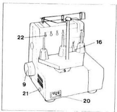
text_image
22 16 9 21 20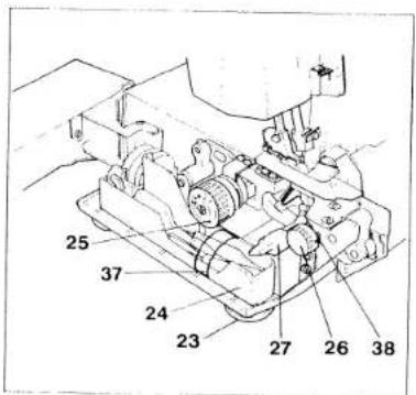
text_image
25 37 24 23 27 26 38Parts of the sewing machine
1 Thread spool stand
2 Carrying handle
3 Needle thread tension dial
4 Housing cover
5 Right looper thread tension dial
6 Left looper thread tension dial
7 Thread tension cover
8 Lint box
9 Handwheel
0 Looper cover with recess
11 Upper knife
12 Work support (swivel-type)
13 Needle plate
14 Sewing foot
15 Needle bar
16 Sewing foot lifting lever
17 Thread spool holder
18 Thread guides
19 Thread guide bar
20 Machine socket
21 Master switch
22 Rear thread guide (4 x)
23 Feet
24 Accessory box
25 Stitch length adjustment knob
26 Seam width adjustment knob
27 Rotary lever for upper knife
disengagement
28 Foot control
29 Foot control plug for machine socket
30 Mains plug
31 Right looper
32 Left looper
33 Lower knife
34 Lower knife retaining screw
35 Retaining screw of upper knife
36 Thread spool centering piece
37 Accessories retainer
38 Retaining screw for blocking the upper knife

natural_image
Technical line drawing of a mechanical component with labeled part '8' (no text or symbols beyond label)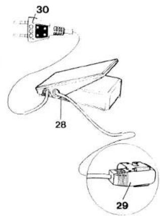
text_image
30 28 29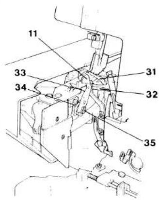
text_image
11 33 34 31 32 35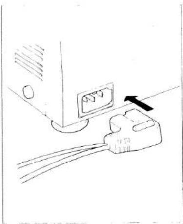
natural_image
Line drawing of a computer interface with an attached plug and cable (no text or symbols)Electrical connection
Use this machine only on a flat surface or on a special sewing table.
Connecting the foot control:
Insert the plug of the control in the machine socket. Then connect the mains plug to a power source.
Caution: When the machine is not in use, switch it off at the master switch and disconnect the plug from the power source. Do not place any objects on the foot control.

natural_image
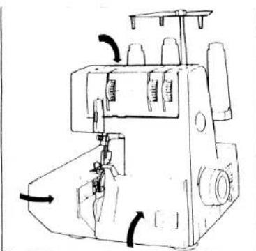
Line drawing showing two views of a computer monitor with a left-side control knob (no text or symbols)Switching the machine ON and OFF
Power and sewing light are switched on and off simultaneously with master switch 12.
Switching on:
Press switch. Machine and sewing light are switched on.
Switching off:
Press switch again. Machine and sewing light are switched off.
text_image
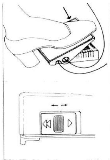
Technical diagram showing a device with labeled ports and directional arrows, including a play button icon.Foot control
The speed of the Hobbylock is regulated as follows:
The more you press the foot control down, the faster the machine will sew.
Electronic foot control
Maximum speed can be pre-selected in two steps by the switch on the foot control.
Position ▶ = Half speed Position ◀◀ = Full speed
Notes on safety
A) Owing to the up and down movement of the needle and the upper knife, the user must take sufficient care to avoid injury and observe the sewing area continuously while sewing.
B) When leaving the machine, changing parts or accessories, the machine must be disconnected from the power source.
C) The maximum approved wattage of the light bulb is 15 watts.
D) The drive belt must never be adjusted by anyone but an authorized Pfaff agent.
text_image
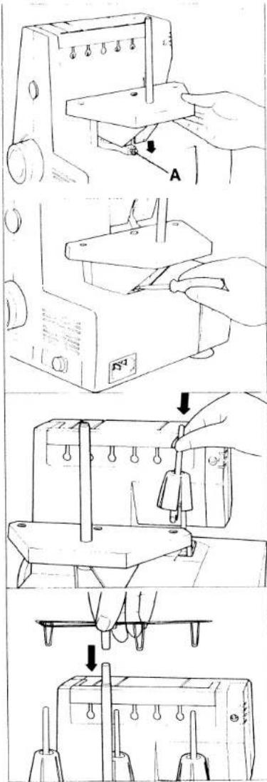
Technical diagram showing five steps of a sewing machine operation with labeled parts A and B, including hand positioning and tool path.Installing the thread spool stand
Loosen clamp screw A a little and pull washer up to the screw head. Insert thread spool stand 1 from the top.
Tighten clamp screw A securely
Insert four thread spool holders 17 with centering pieces 36 fully in the holes of the thread spool stand.
Push thread guiding part 18 into guide bar 19.
Pull up guide bar and align it so that thread guides 18 are exactly above the spool holders.
natural_image
Technical line drawings of mechanical components and assembly (no text or symbols)Opening and closing looper cover and work support
Push looper cover fully to the right, hold it, and swing it down.
To close the looper cover, push it up until it locks.
To open work support 12, push it to the left. To close the work support, push it to the right until it locks.
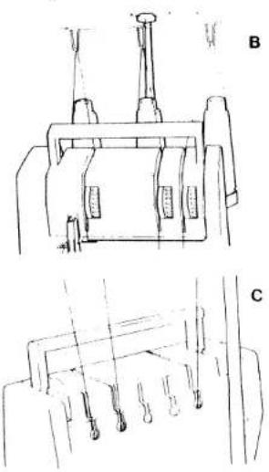
A threading diagram is fixed to the machine behind the looper cover. This diagram shows the different threading paths by different colors (see Fig. A).
natural_image
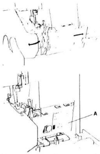
Technical line drawings of mechanical components labeled B and C, showing assembly or assembly steps without any text or symbols.Threading the guide wire of the thread spool stand and the thread guides behind the carrying handle
The machine must be threaded correctly. First pull the respective threads through their corresponding guides (Figs. B and C).
Then thread the tensions in the following sequence:
- right looper (red)
- left looper (yellow)
- needle (blue)
Figure B shows the threading path of the individual threads for thread guides 18. For threading the guides behind carrying handle 2, the handle must be pulled up (Fig. C).
After threading carrying handle 2 must be pushed down again.
text_image
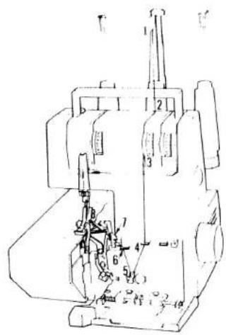
Technical diagram of a sewing machine with numbered components and labeled partsThreading the right looper:
Thread the right looper in sequence 1 to 8 and pull approximately 10 cm (4") of thread through the looper eye (the thread path is marked red).
important.
In order to obtain perfect sewing results, the thread must be pulled between the tension discs when threading the tensions.

text_image
Technical diagram of a mechanical assembly with numbered components for identification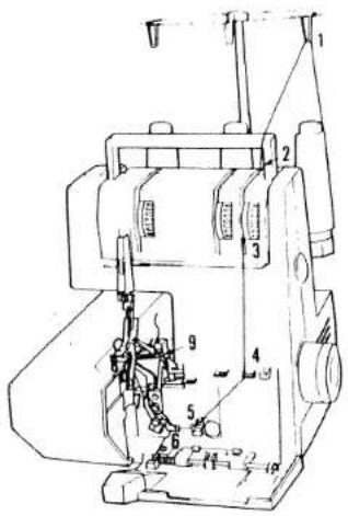
text_image
Technical diagram of a sewing machine with numbered components for identificationThreading the left looper:
Insert the left looper thread in sequence 1 to 9 and pull approximately 10 cm (4") of thread through the looper eye (the thread path is marked yellow).

text_image
Technical diagram of a mechanical assembly with numbered components and labeled parts
text_image
Technical diagram of a sewing machine with numbered components for identificationThreading the needle
Threading of guide wires 18 and of the thread guide behind the carrying handle is shown on page 7.
In the left-hand illustration the threading path is shown from the blue tension (1) up to the right needle (6). At point 5 the thread must be pulled behind the thread retainer.
natural_image
Line drawing of a sewing machine with no visible text or symbolsAfter threading the machine, push handle 2 down, and close work support 12 and looper cover 10.
Thread spool change on threaded machine
Cut the threads close to the thread spool. Place new thread spools on spool holders 17. Tie the threads still in the machine and the new threads together. Pull the needle thread out of the needle. Now pull at the thread ends until the knots are about 15 cm past the last thread guide before the needles. Cut the knots off and pull the threads through the respective needle eyes. The looper threads can be pulled until past the looper eyes without interruption. Pull about 10 cm of thread through the looper eye.
natural_image
Line drawing of a sewing machine with a sewing machine base and a hand operating it (no text or symbols)Inserting the lint box:
Insert the two tabs of the lint box downwards in the recess of the looper cover. Then push the bottom of the box against the machine
For removal of the lint box, use the reverse order.
natural_image
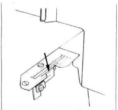
Line drawing of a sewing machine needle and foot (no text or symbols)Seam allowance
If the cutting is guided along below marking N on the looper cover, a seam allowance of 16 mm must be taken into consideration when cutting the fabric.
natural_image
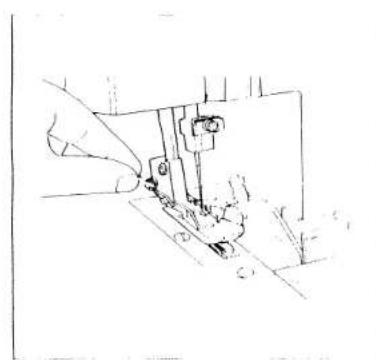
Line drawing of a mechanical assembly or assembly with no visible text, numbers, or symbolsSewing test
After threading, a sewing test test should be made.
Raise sewing foot lever 16, as shown in the illustration
natural_image
Line drawing of a sewing machine needle stitching fabric (no text or symbols)Insert test fabric up to the upper knife and lower the sewing foot.
natural_image
Line drawing of a hand operating a sewing machine needle (no text or symbols)Hold thread ends with your left hand while turning hand wheel with your right hand in the direction indicated by the arrow on the wheel. Lay the threads back under the sewing foot. Make sure that threads have interlocked correctly.

natural_image
Line drawing of a sewing machine needle stitching fabric (no text or symbols)Points to observe during sewing
Place the fabric completely under the sewing foot when starting to sew. (Also after the machine has been rethreaded)
Sew the first stitches slowly.
Since the fabric is fed automatically do not pull or push the fabric. Use your hand for guiding only.
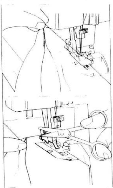
natural_image
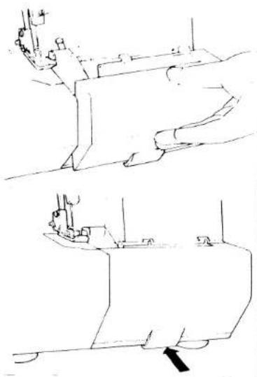
Technical line drawing showing two views of a sewing machine needle and fabric work (no text or symbols)Sew approximately 5 cm beyond the end of the seam and use a scissors to cut the thread chain.
Securing the seam:
Knot the thread chain. For knit fabrics, a crochet needle can be used to pull the thread chain into the seam
Or:
Sew about 5 cm (2") beyond the end of seam. Then turn the workpiece around and sew a few stitches over the seam just sewn without cutting the thread chain.
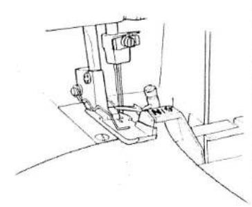
Blocking the upper knife
Sewing very thick fabrics and workpieces with different thicknesses:
On this machine, all kinds of fabric from extremely thin to extremely thick can be processed. When sewing extremely thick fabrics or workpieces with different thicknesses, the screw of the upper knife must be tightened, as shown in the illustration.
By tightening the screw, axial movement of the upper knife is inhibited.
Note:
When sewing thin or medium fabrics, the screw of the upper knife holder must be loosened by about 2 turns, so that the upper knife can move axially.

natural_image
Technical line drawing of a mechanical assembly with a tool and component (no text or symbols)
text_image
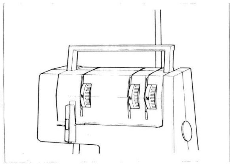
Reverse side Left looper thread Right looper thread Needle Top sideSetting the standard thread tension N
The thread tension to be set depends on the fabric type and thread size used. Set the N on the thread tension dials opposite the front edge of thread tension cover 7 (see illustration below).
Make the correct adjustment after examination of the interlocking of threads (the illustration on the left shows a correct seam)
Page 16 lists examples for correction of the individual thread tensions.
natural_image
Line drawing of a sewing machine with two circular buttons and handle (no text or symbols)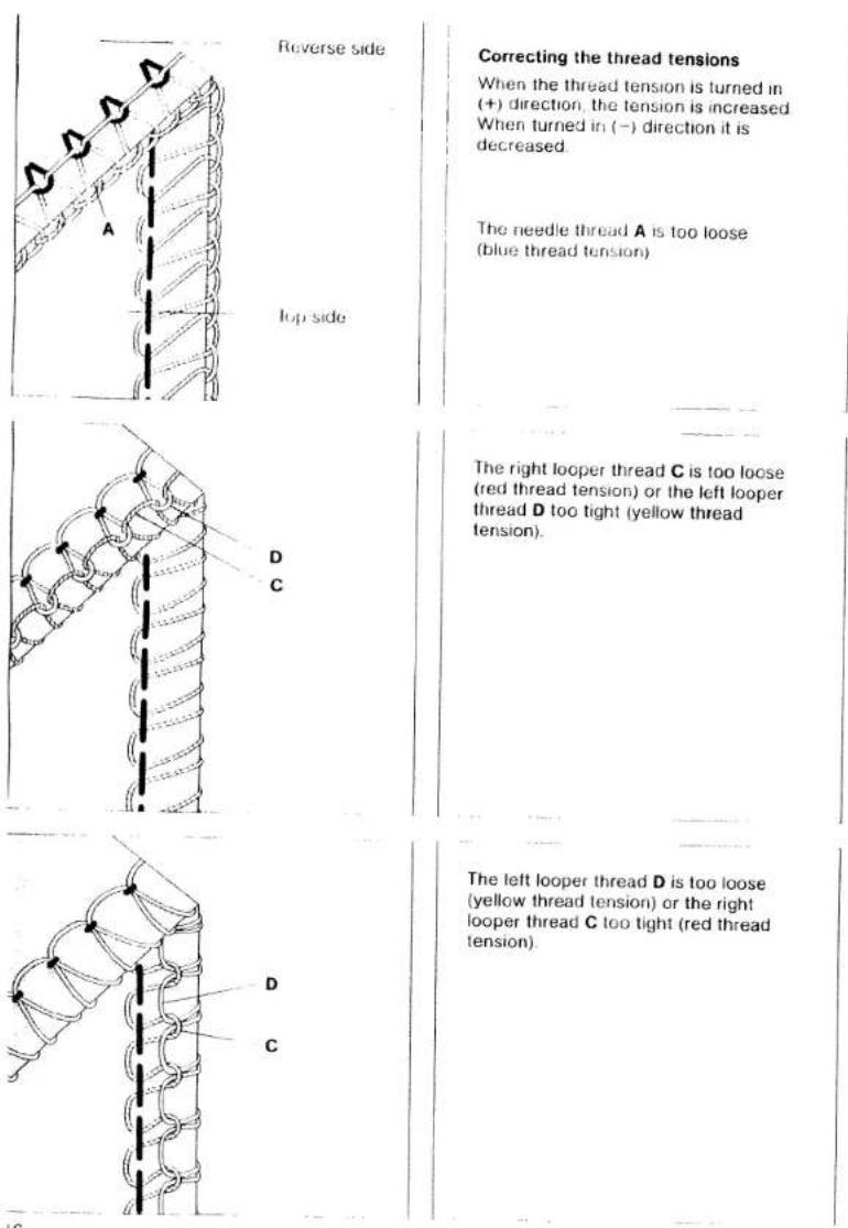
Correcting the thread tensions
When the thread tension is turned in (+) direction, the tension is increased. When turned in (-) direction it is decreased.
The needle thread A is too loose (blue thread tension)
The right looper thread C is too loose (red thread tension) or the left looper thread D too tight (yellow thread tension).
The left looper thread D is too loose (yellow thread tension) or the right looper thread C too tight (red thread tension).
Thread chart for 3-thread overedge seam
| Material | Thread | Stitch length | |
| Light materials: | |||
| Organdy, light knit fabric, Taffeta, silk, lining materials | Cotton | No. 80-100 | 20 to 40 mm |
| Silk | No. 80-100 | ||
| Synthetic thread | No. 70-140 | ||
| Medium-heavy materials: | |||
| Cotton, tricot, linen, dress materials | Cotton | No. 60-100 | 20 to 40 mm |
| Silk | No. 50-100 | ||
| Synthetic thread | No. 70-140 | ||
| Heavy materials: | |||
| Tweed, suit materials, denim, heavy cloth | Cotton | No. 40-60 | 20 to 50 mm |
| Silk | No. 40-60 | ||
| Synthetic thread | No. 70-140 | ||
| Knit fabrics: | |||
| Rolled hem | Cotton | No. 40-60 | 20 to 50 mm |
| Silk | No. 40-60 | ||
| Synthetic thread | No. 70-140 | ||
| Polyester thread | No. 120-140 | 1.0 to 2.0 mm | |
| Mercerized thread (bulk thread) | |||

natural_image
Technical line drawing of a mechanical assembly with no visible text or symbolsSetting the stitch length
Open work support 12. Hold hand wheel 9 fast and set stitch-length adjustment knob 25 at the stitch length desired between 1 and 5 mm. Standard setting N is 3 mm.
natural_image
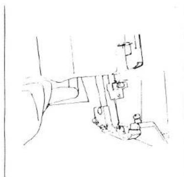
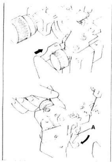
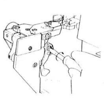
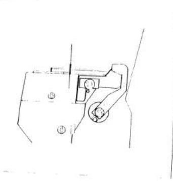
Illustration of a person using a camera and a device, showing motion phases (no text or symbols)Disengaging the upper knife
Remove lint box 8. Open work support 12 and looper cover 10 If necessary, loosen screw 38 for axial upper knife blocking
Push rotary lever 27 of the axial upper knife guide fully to the right, hold it, and turn it forwards until pin A engages in the hole of the knife. Now the upper knife is disengaged.
natural_image
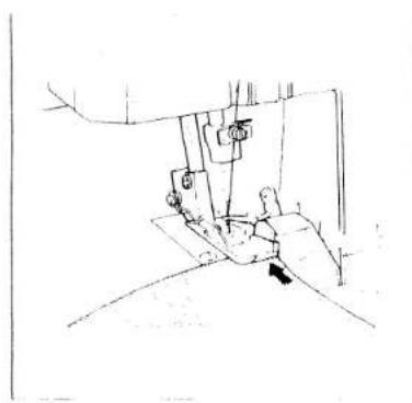
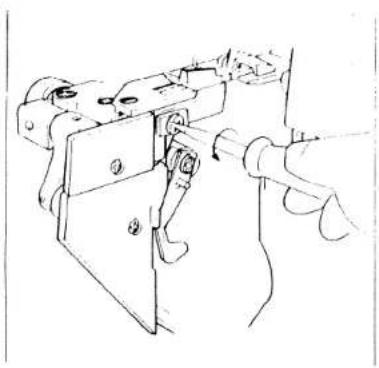
Line drawing of a hand operating a mechanical device with no visible text or symbolsAdjusting the seam width
The standard seam width setting is marked with N (3.5 mm).
Disengage the upper knife according to the above description.
The desired seam width is set with adjusting knob 26. The scale on the seam-width adjustment knob ranges from 3 to 5.
Set the upper knife at its basic position again and close the looper cover.
When processing thick fabrics, securely tighten screw 38 for blocking the upper knife, see page 14.
Sew a test seam
Note:
After adjusting the seam width, it may be necessary to re-adjust the thread tension.

text_image
F H GChanging the sewing foot
Raise sewing foot lifting lever 16.
Disengage the sewing foot by pressing lever F
Engage the sewing foot.
Place the sewing foot under the sewing foot holder so that when you lower the sewing foot lifting lever, crosspiece G of the foot engages in groove H of the sewing foot holder.
The illustration on the left shows a correctly engaged sewing foot.

text_image
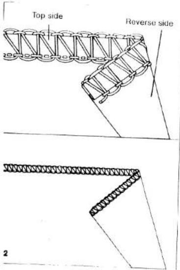
Top side Reverse side 1Rolled hem
sewn with polyester thread 120-140
A rolled hem is used for light, delicate fabrics and is an attractive finish for open edges. Without any effort you can sew professional rolled hems on neck scarves, shawls and valances (see page 21).
text_image
Top side Reverse side 2Rolled hem with polyester thread
Preparation of the sewing machine:
Needle insert needle
Sewing foot. engage rolled hem foot "R
Seam width. from 30 to 40 mm (depending on material)
Stitch length: from 10 to 20 (short stitch length)
Thread: polyester thread 120-140 for blue, red and yellow thread tensions
Threading path:
| 1 | right looper, red path | polyester thread |
| 2 | left looper, yellow path | polyester thread |
| 3 | needle thread, blue path | polyester thread |
For threading of needle and loopers, see pages 7 to 11
Tension setting: round edge, Fig. 1 flat edge, Fig. 2
| Red thread tension, right looper | approx. "N" | approx. +5 |
| Yellow thread tension, left looper | +5 | approx. "N" to -1 |
| Blue thread tension, needle thread | approx. "N" | approx. "N" to +1 |
Depending on material and thread, the respective thread tension must be set higher or lower
Rolled hem, sewn with bulk thread:
This hem requires three threads, one bulk thread and two polyester threads 120-140
Preparation of the machine, as described above.
Thread: bulk thread - red tension polyester thread 120-140 for blue and yellow tensions
Threading path:
| 1. right looper, red path | bulk thread |
| 2. left looper, yellow path | polyester thread 120-140 |
| 3. needle thread, blue path | polyester thread 120-140 |
For threading of needle and loopers, see pages 7 to 11
| Tension setting: | round edge, Fig. 1 | flat edge, Fig. 2 |
| Red thread tension, right looper | approx. "N" to -3 | approx. "N" to +5 |
| Yellow thread tension, left looper | approx. +5 | approx. "N" |
| Blue thread tension, needle thread | approx. "N" | approx. "N" |
Note:
Rolled hems can also be sewn with two bulk threads and one polyester thread. The bulk threads must then be threaded in the left and right looper
Depending on material and thread, the respective thread tension must be set higher or lower.

natural_image
Pure mechanical diagram showing a lever mechanism with rotational arrows, no text or symbols present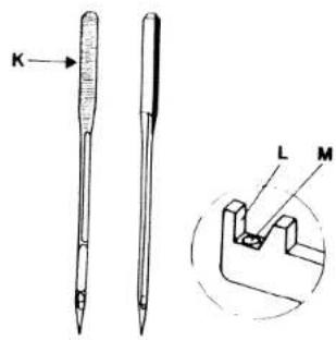
text_image
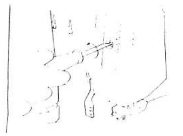
K L MChanging the needle
Pull out the mains plug. Lower the sewing foot. Turn the hand wheel in the direction of the arrow until the needle bar is at its highest position. Use the needle change tool from the accessories (see p. 31, item 11) as follows: Insert the needle in hole M of the needle change tool. Loosen the set screw of the needle with the screw driver. Remove the needle by pulling it downwards.
Inserting the needle
Insert the needle in hole M of the needle change tool in such a way that flat side K of the needle shank faces surface L of the needle change tool. Then push the needle up into the needle holder as far as it will go. Tighten needle set screw securely. Remove needle change tool from the needle.
Notes:
The following needles are used on these machines: System 130/705 H (75-90) Although the correct needle size depends on the material and the thread size used, we recommend needle size 75-90. An incorrectly inserted needle will cause thread breakage and skipped stitches.

natural_image
Line drawing of a hand holding a small object with a labeled arrow (no text or symbols present)Changing the knives
Knives are available as spare parts.
Pull out the mains plug
Disengage the upper knife, see page 18.

natural_image
Simple line drawing of a person standing near a vehicle, possibly a robot or robotic arm (no text or symbols)Changing the upper knife:
Pull out the mains plug.
Unscrew knife retaining screw 35 and remove upper knife
natural_image
Line drawing of a hand operating a mechanical device with a tool (no text or symbols visible)Insert the new upper knife and tighten its retaining screw securely.
natural_image
Pure mechanical component diagram without any text, numbers, or symbolsSet upper knife with knife guide 27 up (cutting position). Turn the handwheel until the upper knife is at its lowest position.
In this position, the front edge of the upper knife must be 0.5 to 1 mm below the needle plate surface.
natural_image
Technical line drawing of a mechanical clamp or bracket assembly (no text or symbols)Changing the lower knife
Pull out the mains plug!
Disengage the upper knife (see page 18). Remove retaining screw 34 of the lower knife.

natural_image
Line drawing of a hand holding a metal bracket with mounting holes (no text or symbols)Place the new lower knife against the left guide of the lower knife holder and push it up, as shown in the illustration. Replace the screw with the pressure plate.
natural_image
Technical line drawing of a mechanical clamp or bracket assembly (no text or symbols)Align the cutting edge of the lower knife so that it is flush with the needle plate surface.
Before tightening the retaining screw, align the pressure plate. Reset the upper knife to cutting position.
natural_image
Simple line drawing of a hand holding a small object, possibly a tool or device, with no visible text or symbols.Changing the light bulb:
Pull out the mains plug.
Loosen housing cover retaining screw 4
Open the housing cover.
Behind it, the light bulb of the sewing light is situated

natural_image
Sketch of a person standing near a vehicle, possibly a robot or robotic arm, with no visible text or symbols.Removing the light bulb:
Push the light bulb upwards and turn it fully to the left
Inserting the light bulb:
Insert the new bulb (15 Watt max.) with the pins in the slots, push it up and turn it fully to the right.
Close and fasten housing cover.
natural_image
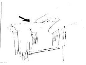
Simple line drawing of a desk with a chair and a pen, no text or symbols presentCleaning the thread tensions:
Pull thread tension cover 7 with both hands to the front (direction of arrow) and remove it.

text_image
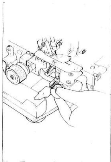
Technical diagram showing a hand operating a mechanical device with labeled component A and internal componentsUse the brush provided with the accessories to remove dust and lint from between the tensions.
Replace the thread tension cover by engaging the tabs of the cover in retainers A of the housing.
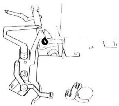
Oiling the machine:
Every time before you take the machine into operation, you should apply a little oil to the places indicated. The bushings and other important moving parts are made of special material and need to be oiled only once or twice a month. One to two drops of high quality sewing machine oil are sufficient for oiling.
natural_image
Technical line drawing of a mechanical device with no visible text or symbols
natural_image
Technical line drawing of a mechanical clamp or bracket with two circular holes and a droplet symbol (no text or labels)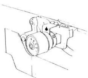
natural_image
Technical line drawing of a mechanical assembly (no text or symbols)2.1. 3.1. 4.1. 5.1. 6.1. 7.1. 8.1. 9.1. 10.1. 11.1. 12.1. 13.1. 14.1. 15.1. 16.1. 17.1. 18.1. 19.1. 20.1. 21.1. 22.1. 23.1. 24.1. 25.1. 26.1. 27.1. 28.1. 29.1. 30.1. 31.1. 32.1. 33.1. 34.1. 35.1. 36.1. 37.1. 38.1. 39.1. 40.1. 41.1. 42.1. 43.1. 44.1. 45.1. 46.1. 47.1. 48.1. 49.1. 50.1. 51.1. 52.1. 53.1. 54.1. 55.1. 56.1. 57.1. 58.1. 59.1. 60.1. 61.1. 62.1. 63.1. 64.1. 65.1. 66.1. 67.1. 68.1. 69.1. 70.1. 71.1. 72.1. 73.1. 74.1. 75.1. 76.1. 77.1. 78.1. 79.1. 80.1.
these machines have been developed for easy operation, and there are no difficult adjustments to be made. Sewing problems of the kind described below may occur due to minor adjustment- and peration errors. They can easily be corrected by following the instructions below.
| Problem | Cause | Solution |
| Needle breakage | Needle bent or point damaged | Insert new needle |
| Needle not fully inserted | Insert new needle correctly (see page 22) | |
| Material pulled | Do not pull material during sewing | |
| Thread breakage | Incorrectly threaded | Thread correctly (see pages 7-10) |
| Thread has caught | Check whether thread catches at the reel stand, etc. | |
| Thread tension too tight | Regulate tension, (pages 15, 16) | |
| Needle not fully inserted | Insert needle correctly (page 22) | |
| Incorrect needle used | Use needle system 130/705 H | |
| Skipped stitches | Needle bent or point damaged | Insert new needle |
| Needle not fully inserted | Insert needle correctly (page 22) | |
| Incorrect needle used | Use needle system 130/705 H | |
| Incorrectly threaded | Thread correctly (pages 7-10). | |
| Incorrect stitch formation | Incorrect setting of thread tensions. | Set thread tensions correctly (pages 15, 16) |
| Puckered seams | Thread tension too tight | Reduce thread tension (especially for light materials) (pages 15, 16). |
| Incorrect setting of differential feed. | Re-adjust differential feed. | |
| Thread has caught due to incorrect threading | Thread correctly (pages 7-10). |
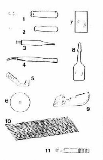
Accessories
1 Screwdriver (big)
2 Screwdriver (small)
3 Lint brush
4 Tweezers
5 Upper knife
6 Thread unreeling disc
7 Needles
8 Sewing machine oil
9 Rolled hem sewing foot
0 Thread spool net
1 Needle change tool
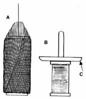
Thread spool net
Very useful for synthetic threads which tend to become loose, unravel and slip down (Fig. A)
Thread unreeling disc
The thread unreeling disc shown as item 6 of the accessories is used for smaller thread spools.
Remove thread spool centering piece 36 from the thread reel pin.
Put the thread spool on the thread reel pin and place the thread unreeling disc on top of it, with rounded-off section C facing down, as shown in Fig. B.
Specifications:
| Maximum sewing speed | 1,300 stitches/min |
| Seam width | 3-5 mm |
| Stitch length | 1-5 mm |
| Sewing foot | Hinged |
| Lubrication | Manual |
| Sewing foot height | 5 mm |
| Needle system | 130/705 H (no. 75 - no. 90) |
| Number of threads | 4 |
| Dimensions | 315 x 280 x 330 mm |
| Weight | approx 80 kg |
Contents of cardboard box
1 machine with motor
1 foot control
1 instruction manual/guarantee certificate
1 lint box
1 thread spool stand
4 thread spool stand bars
1 thread guide
1 machine cover