hobbylock 774 - Sewing machine PFAFF - Free user manual and instructions
Find the device manual for free hobbylock 774 PFAFF in PDF.

User questions about hobbylock 774 PFAFF
0 question about this device. Answer the ones you know or ask your own.
Ask a new question about this device
Download the instructions for your Sewing machine in PDF format for free! Find your manual hobbylock 774 - PFAFF and take your electronic device back in hand. On this page are published all the documents necessary for the use of your device. hobbylock 774 by PFAFF.
USER MANUAL hobbylock 774 PFAFF
natural_image
Line drawing of a sewing machine with gauges and a stand (no text or symbols)CONTENTS
A. Parts names 2
B. Preparation for the sewing 4
a. Preparation.... 4
b. Fitting the foot controller.... 4
c. How to adjust the foot controller 4
d. Turning on / off the lamp. 4
e. Labrication 5
f. Opening and closing looper cover and side cover 6
g. Threading procedure 6
C. Operating the machine. 9
a. Test sewing 9
b. Thread tension adjustment (Normal hemming) 9
c. Dial chart for thread tension adjustment 9
d. Relation chart for fabrics and thread stitch length. 10
e. Correct thread tension....10
f. Incorrect thread tension and how to adjust 11
g. Roll hemming 12
h. Points to obseave during sewing....13
i. 3-thread overedge seam 14
D. Some adjustments / Maintenance.... 15
a. Adjusting the seam width 15
b. Adjusting the stitch length 15
c. Replacing needle (s) 16
d. Replacing the upper knife 17
e. Replacing the lower knife 18
f. Replacing the light bulb 19
E. Sewing problems and solutions 20
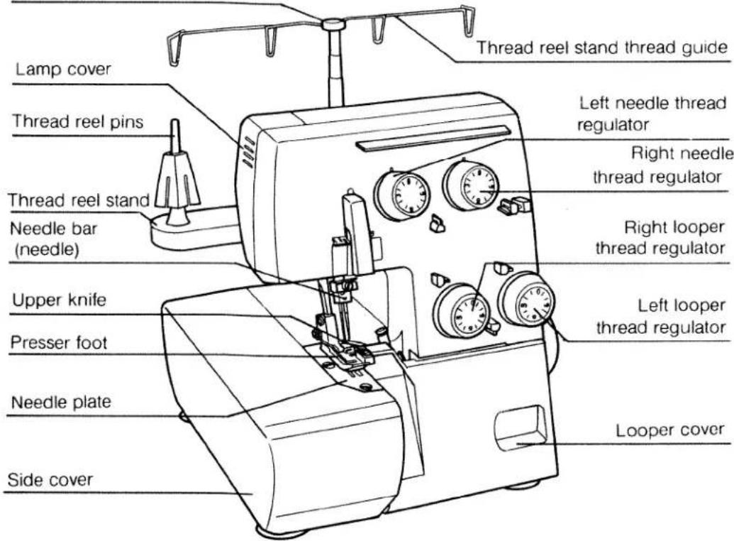
A. Parts name
- Front side
Telescopic thread reel stand bar
text_image
Lamp cover Thread reel pins Thread reel stand Needle bar (needle) Upper knife Presser foot Needle plate Side cover Thread reel stand thread guide Left needle thread regulator Right needle thread regulator Right looper thread regulator Left looper thread regulator Looper cover- Rear side

text_image
Rear side Pulley wheel Master switch Power socket Presser foot lifting hand lever Rubber cushion feet- Accessories
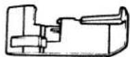
natural_image
Simple line drawing of a rounded rectangular shape with a small protrusion on the top-left corner (no text or symbols)Accessories case
Screw driver

Screw driver
(For needle)

Tweezers

Oiler
- Specifications
Maximum speed
Overlock seam width
Stitch length
Presser foot
Presser foot lift
Needle
Number of threads
Lubrication
Dimentions
Net weight
1,300 s.p.m.
3.5mm (standard)
1.0 \~ 5.0mm
Hinged
5mm
130/705H No.75\~No.90
4
Manual
278(W) × 264(D) × 310(H)
7Kg

Brush for dusting
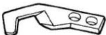
Upper knife

Needle
Roll hemming presser foot

Thread stripping discs (4 pcs.)
natural_image
Simple line drawing of a folded or rolled document (no text or symbols)Dust cover
- Looper mechanism
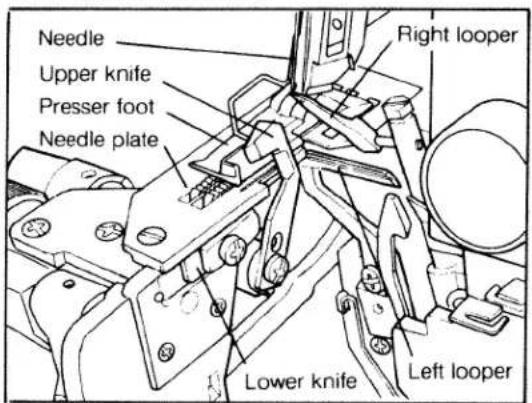
text_image
Needle Upper knife Presser foot Needle plate Right looper Lower knife Left looper- Controller
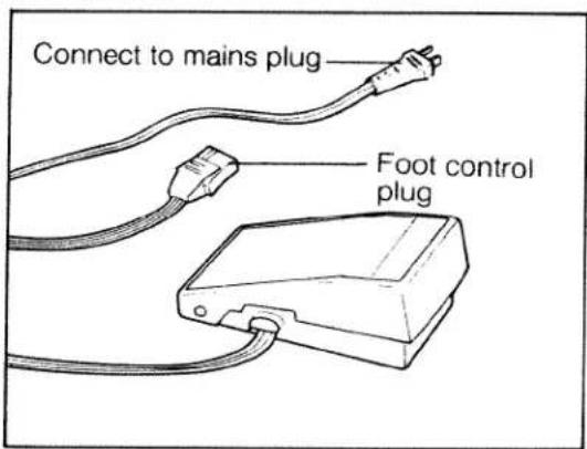
text_image
Connect to mains plug Foot control plugB. Preparation for the sewing
a. Preparation
This machine must be used on a flat and horizontal surface or purpose-built sewing machine table.
b. Fitting the foot controller
First, insert the controller connector into the connector socket on the machine as shown in the illustration, then connect the plug to a power source.
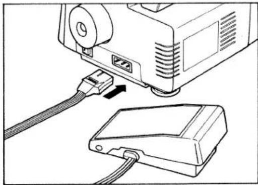
natural_image
Line drawing of a projector connected to a device via cable (no text or symbols)c. How to adjust the foot controller
Place the tip of your foot lightly on the pedal. When you press down gently, the machine will begin to run at low speed: As you press more heavily the machine will run faster. To stop the machine, lift your foot from the pedal.
d. Turning on / off the lamp
Sewing light is switched on and off by the master switch located right side of the body. By switching on the machine, sewing light is turned on and by switching off the machine, sewing light is turned off.

text_image
Master switche. Lubrication
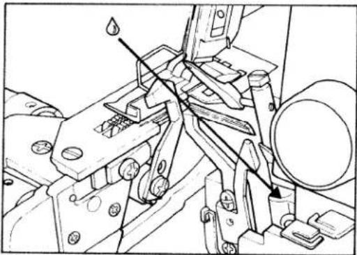
The bushings and other important parts are made from special materials and only require lubrication once or twice a month. When oiling always be sure to use a good quality sewing machine oil. Apply just one or two drops of oil to the areas indicated.
natural_image
Technical line drawing of mechanical components with no visible text or symbols
natural_image
Technical line drawing of a mechanical assembly with no visible text or symbols
natural_image
Mechanical assembly diagram showing a gear and shaft assembly with no visible text or symbolsf. Opening and closing looper cover and side cover
-
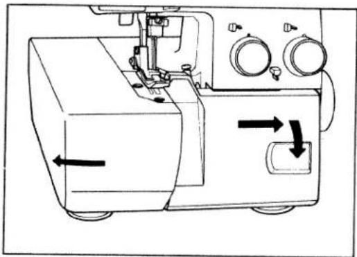
To open the side cover, push it to the direction of the arrow. To close side cover, push it to the right until it locks.
-
To open the looper cover, slide the looper cover to the right, swing it down towards you.
-
To close the looper cover, push the looper cover upwards lightly towards the machine until it clicks and it will close securely.
natural_image
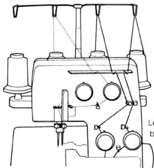
Technical line drawing of a sewing machine with directional arrows indicating movement (no text or symbols)g. Threading procedure
-
Ensure that the telescopic thread guide bar is at maximum vertical height.
-
Threading must be done carefully in accordance with the threading procedure in order to obtain a correctly formed seam.
-
Position the telescopic thread guide bar so that it immediately aligns above the thread reel bar pins.
-
Tweezers from the accessories bag will assist you to make threading easier.

natural_image
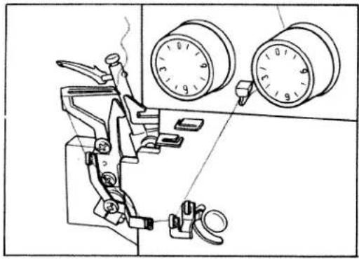
Line drawing of a sewing machine with a spool, needle, and pressure gauge (no text or symbols)1. Threading the left lower looper first
- Leave surplus thread about 5 cm (about 2") beyond looper eye.
natural_image
Technical line drawing of a sewing machine with two circular gauges and clamps (no text or symbols)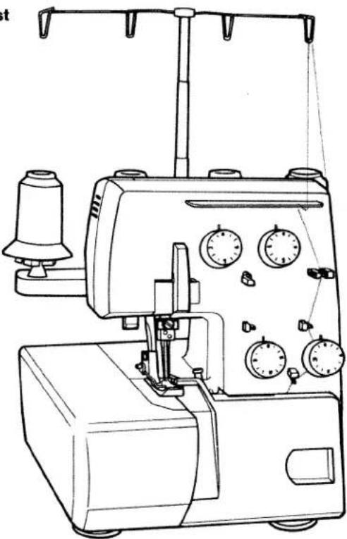
natural_image
Line drawing of a sewing machine with multiple gauges and clamps (no text or labels)- Secondly thread the right upper looper

natural_image
Line drawing of a sewing machine with gauges and serpentine base (no text or symbols)
natural_image
Technical line drawing of a sewing machine with two gauges and clamps (no text or symbols)- Leave surplus thread about 5 cm (about 2") beyond looper eye.
3. Next thread the right needle
natural_image
Technical line drawing of a sewing machine with no visible text or symbolsLeave surplus thread about 5 cm (about 2") beyond needle eyes.
4. Lastly thread the left needle

natural_image
Technical line drawing of a sewing machine with no visible text or symbolsLeave surplus thread about 5 cm (about 2") beyond needle eyes.
It would be helpful in the initial stage, (before commencing to sew) that different coloured threads are used. Similar to those illustrated on the Tension Dial Diagram (4), this will identify the threads being used with respective needle and looper.
Once you are satisfied that the tension balance is correct (page 10) tie on those threads that are to be used.
Be careful when passing these threads through the machine, so as to avoid any breakage of thread that may occur if due care is not taken.
Then proceed to sew with caution until you are satisfied that the correct results are achieved.
C. OPerating the machine
a. Test sewing
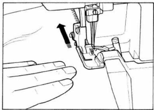
After threading, be sure to make a test sewing before actual operation.
Procedure
- Hold the 4 threads by your left hand and turn the pulley 2 or 3 turns slowly towards you with your right hand.
Checking the threads being interlocked.
- Insert the cloth under the presser foot up to the edge of the upper cutter and start sewing slowly.

natural_image
Technical line drawing of a sewing machine needle stitching a component (no text or symbols)b. Thread tension adjustment (Normal hemming)
The correct thread tension varies depending on the fabric and type and thickness of the thread and must therefore be adjusted accordingly. By referring to the chart below it will assist you in achieving the best results.
c. Dial chart for thread tension adjustment
| Thread Fabrics | Thread | Dial for L. needle | Dial for R. needle | Dial for R. looper | Dial for L. looper | Presser foot | |||
| L. needle | R. needle | R. looper | L. looper | ||||||
| Broad 1 ply | Spun # 80 | Spun # 80 | Spun # 80 | Spun # 80 | 3 | 3 | 3 | 3 | for Normal hemming |
| Denim 2 plies | * | * | * | * | 4 | 4 | 3 | 3 | |
| Georgette 2 plies | * | * | * | * | 2 | 2 | 3 | 3 | |
- Narrow hemming
| Broad 1ply | Spun#80 | Spun#80 | Spun#80 | Spun#80 | — | 3 | 6 | 3 | forRollhemming |
| Georgette 1 ply | * | * | * | * | — | 2 | 6 | 3 |
- Fold-over hemming
| Broad 1ply | Spun#80 | Spun#80 | Spun#80 | Spun#80 | — | 3 | 3 | 10 | forRollhemming |
| Georgette 1ply | * | * | * | * | — | 2 | 3 | 10 |
d. Relation chart for fadrics and thread stitch length
| Fabrics | Thread | Stitch length | |
| Normal hemming | LightOrgandy, light-knit fabric,Taffeta, silk,lining materials | Cotton No.80-100Silk No.80-100Synthetic thread No.80 | 3.0 to 4.0mm |
| MediumCotton, tricot, linen,dress materials | Cotton No.60-100Silk No.50-100Synthetic thread No.60-80 | 3.0 to 4.0mm | |
| HeavyTweed, suit materials,denim, heavy cloth | Cotton No.40-60Silk No.40-60Polyester thread No.30-60 | 3.0 to 4.0mm | |
| Knit fadrics | Polyester thread No.50-80Synthetic thread No.60-80Woolly nylon | 2.0 to 4.0mm | |
| Roll hemming | georgette tricot | Polyester thread No.80-100Synthetic thread No.80-100Woolly nylon | 1.0 to 1.5mm |
e. Correct thread tension
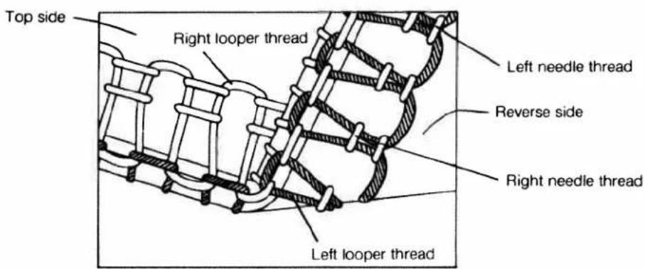
text_image
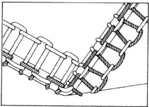
Top side Right looper thread Left needle thread Reverse side Right needle thread Left looper threadf. Incorrect thread tension and how to adjust
-
The sketch shows the left needle thread tension is too loose.
-
The sketch shows the right needle thread tension is too loose.
-
The sketch shows the right looper thread tension is too loose.
-
The sketch shows the left looper thread tension is too loose.

natural_image
Technical line drawing of a mechanical assembly with no visible text or symbols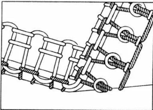
natural_image
Technical line drawing of a mechanical assembly with interlocking components (no text or symbols)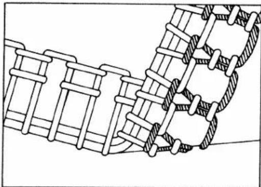
natural_image
Technical line drawing of a mechanical assembly with interlocking components (no text or symbols)
natural_image
Technical line drawing of a mechanical spring or mesh connection (no text or symbols)g. Roll hemming
- Roll hemming foot
● Normal hemming foot
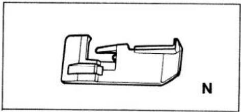
natural_image
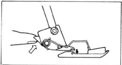
Technical line drawing of a mechanical component with no visible text or symbols● How to replace the presser foot
natural_image
Line drawing of a sewing machine needle stitching a piece of material (no text or symbols)
natural_image
Line drawing of a sewing machine needle and foot (no text or symbols)- Correct thread tension of roll hemming

text_image
Top side Reverse side Narrow hemming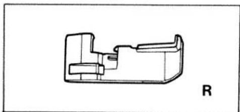
natural_image
Technical line drawing of a mechanical component with no visible text or symbolsRemove the left needle first. For the roll hemming (narrow / foldover hemming) replace the normal stitch foot by the roll hemming foot. By following this instruction, very good sewing results can be achieved.
- Raice the presser foot and then push up the small lever. The foot for normal sewing can then be taken off.
- With the presser foot still raised, place the roll hemming foot under the shank and lower the shank until connecting points are in contact, then lower the presser foot and the new foot will then be engaged.

text_image
Top side Reverse side Fold-over hemmingh. Points to observe during sewing
- Place the fabric under the cutter and lower the foot before commencing to sew.
- Then slowly sew the first few stitches, the fabric will feed automatically and gently guide by hand.
- Do not push or pull the material so as to avoid the possibility of breaking the needles.
Caution pushing or pulling of fabric can result in needle breakage and cause further damage to needle plate, and looper mechanism.
- For finishing a seam, sew approximately 5 cm beyond the end of the seam then cut the thread chain.
• Securing the seam:
Tie the thread chain. For knit fabric, a crochet needle can be used to pull the thread chain into the seam.
• To prevent unravelling of seams, sew approximately 5 cm beyond the seam. Then, flip fabric over and sew over the seam approximately 2 cm.
- This machine will sew from fine to very heavy fabrics. When sewing very heavy fabrics, tighten the upper knife screw. (see illustration).
• Caution:
When sewing fine fabrics, remember to loosen the upper knife screw again if you have been sewing on heavy fabrics.
natural_image
Line drawing of a sewing machine needle stitching a hand, showing no text or symbols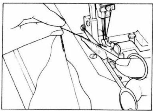
natural_image
Line drawing of a sewing machine needle stitching fabric, no text or symbols present
text_image
Top side Reverse side
natural_image
Mechanical assembly diagram showing a hand operating a tool on a mechanical component (no text or symbols visible)i. 3 thread overedge seam
Three-thread sewing is possible by using either right or left hand needles.
Threading procedure is as usual.
- For wide seam sewing.
- Remove the right hand needle.
- Use the left hand needle thread and right & left looper thread.
- Seam width can be changed from 5 mm to 7 mm. (Standard seam width is 5.5 mm).
-
For narrow seam sewing.
-
Remove the left hand needle.
- Use the right hand needle thread and right & left looper thread.
- Seam width can be changed from 3 mm to 5 mm.(Standard seam width is 3.5 mm).
Wide seam
Use left hand needle only.

Narrow seam
Use right hand needle only.
natural_image
Technical line drawing of a mechanical linkage or conveyor system (no text or symbols)D. Some adjustments / Maintenance
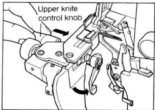
a. Adjusting the seam width
Standard seam width is 3.5 mm. It can be adjusted from 3.0mm to 5.0mm when using the different materials.
-
Open the side cover and looper cover. Push the upper knife control knob firmly to the right and, whilst maintaining pressure, turn the knob and knife towards you downwards, releasing the pressure as the knife is lowered. To raise the knife, simply reverse the operations above.
-
Adjust the required seam width by turning the dial.
text_image
Upper knife control knob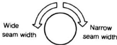
flowchart
graph TD
    A["Wide seam width"] --> B((Circular))
    B --> C["Narrow seam width"]
• After adjusting the seam width, it may be necessary to reset the thread tension.
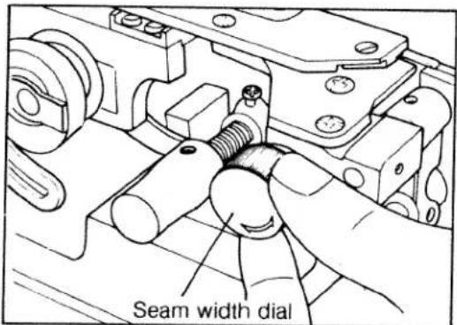
text_image
Seam width dialb. Adjusting the stitch length
-
To change the stitch length, open the side cover.
-
Loosen the feed regulator nut.
-
Align the feed regulator nut and the number on the feed regulator. To make the stitch length longer move the nut to a higher number. To make the stitch length shorter select a lower number.
-
After making the adjustment, tighten the feed regulator nut and close the side cover.
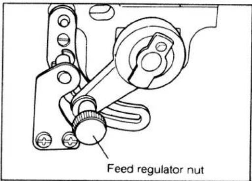
text_image
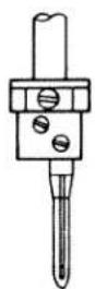
Feed regulator nutc.Replacing needle (S)
DURING THIS OPERATION DISCONNECT THE MAINS PLUG FROM THE POWER SOURCE.
1. Removing needle (s)
Turn the pulley wheel towards you by hand, (in the direction of the arrow), raising the needle (s) to the highest position. Using a screwdriver, loosen the needle clamp screw and remove the needle(s). If necessary, use the tweezers supplied.
2. Fitting new needle(s)
Whilst in this position, insert new needle(s) fully upwards into the needle holder(s) making sure that the long groove in the needle(s) face towards you. Then using a screwdriver, re-tighten the needle clamp screw securely.
The recommended needle system are: 130 / 705H, and the normal recommended size is No. 90.
Depending on the weight of fabric you are using Needle sizes from No. 75 to No. 90 may be used. Light weight materials needing a finer needle, with a thicker needle for heavier weights.
Ensure you carry out this procedure correctly as to not do so could result in thread or needle breakage and also skipped stitches.
ATTENTION
When replacing needles, please take note of the illustrations below :
The needle clamp screw for each needle crosses the other. It is important to properly insert the screws when refitting needles. Take special care not to try to put back the screw straight but rather follow the slant and do not force the screw.

natural_image
Technical illustration of hands operating a sewing machine with a tool, showing mechanical components and a rotation arrow (no text or symbols)
natural_image
Technical line drawing of a mechanical assembly with no visible text or symbolsFitting the left needle
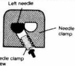
text_image
Left needle Needle clamp Needle clamp row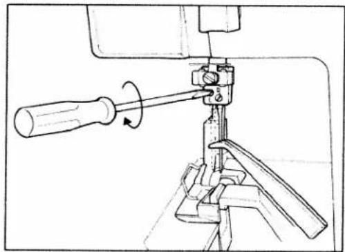
natural_image
Technical line drawing of a mechanical clamp or tool with a screwdriver and lever mechanism (no text or symbols)Fitting the right needle

text_image
Right needle Needle clamp Needle clamp screwd. Replacing the upper knife
DURING THIS OPERATION DISCONNECT THE PLUG FROM THE MAINS OUTLET.
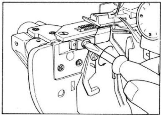
1. To remove the upper knife.
Push into the right, and turn down anti-clockwise towards you, the upper knife release knob, until the knife is held in position by the carrier stopper (approximately horizontal to you).
Then loosen the retaining screw and take off the knife, taking care not to touch the blade.
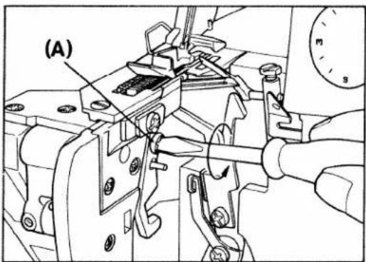
2. Fitting a new upper knife
Place the new knife onto the carrier stopper (in the opposite manner as abnve), and, using a screwdriver, retighten the retaining screw (A) securely.
Turn the release knob away from you, raising the knife to a vertical position, then, by releasing pressure on the knob, the knife will be brought firmly against the lower knife and behind the guard on the presser foot. It is now ready for normal operation.
3. To set the cutting position:
Place the upper knife in the cutting position and, by turning the pulley wheel by hand towards you, lower it to its bottom position at which point the tip of the upper knife should overlap the lower knife by 1.0mm. When in this position, re-tighten the screw (A) securely, using a screw-driver.
If it is necessary to adjust, loosen the upper knife screw (A) and raise or lower as required. Only very tiny movements should be necessary.
text_image
(A)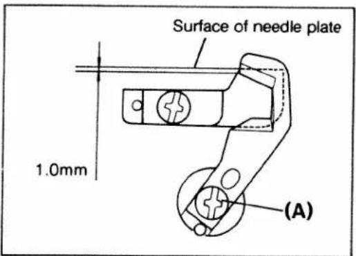
text_image
Surface of needle plate 1.0mm (A)e. Replacing the lower knife
DURING THIS OPERATION DISCONNECT THE PLUG FROM THE MAINS OUTLET
1. To remove the lower knife.
First push into the right the upper knife release knob turning it anti-clockwise to release the upper knife (as described on page 17)
Loosen the lower knife screw and remove the lower knife, taking care not to touch the blade.
2. Fitting a new lower knife
Insert the knife into the groove of the lower knife holder and, with the cutting edge facing right, set the knife so that the cutting edge of the blade aligns with the surface of the needle plate and then re-tighten the fixing screw securely. using a screwdriver.
Replace the upper knife in its working position by means of the release knob (see also page 17).
natural_image
Technical line drawing of a mechanical assembly with no visible text or symbols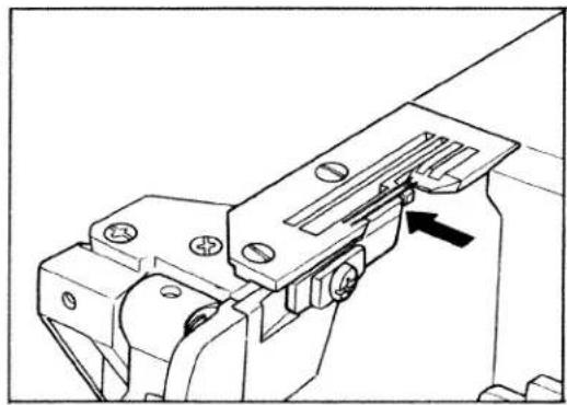
natural_image
Technical line drawing of a mechanical clamp or bracket assembly (no text or symbols)f. Replacing the light bulb
FIRST DISCONNECT THE MAINS PLUG FROM THE POWER SOURCE
- Loosen the screw of the rear of the machine body and remove the lamp cover.
- Turn the bulb in direction (1) and remove it. Insert the new bulb by pushing upward, turning it in the direction (2). Replace cover.
Caution: Use a maximum 15 watt bulb only.

natural_image
Line drawing of a hand using a screwdriver to adjust or install a mechanical component (no text or symbols present)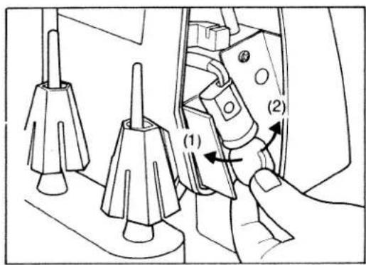
text_image
Technical diagram showing a hand operating a mechanical component with labeled parts (1) and (2), including tool tips and adjustment arrows.E. Sewing problems and solutions
Used correctly, your machine should operate efficiently and without difficulty. However you may from time to time encounter the occasional problem which usually results from not carrying out various adjustments in the recommended manner.
Listed below are the more common problems, together with their simple solution which should overcome most of these difficulties.
| Problem | Cause | Solution |
| Needle breakage | Needle is bent or point damagedNeedle not correctly insertedMaterial pulled | Insert new needle.Insert new needle correctly.Do not pull or push material during sewing. |
| Thread breakage | Incorrectly threadedThread has caughtThread tension too tightNeedle not correctly insertedIncorrect needle used | Thread correctly.Check whether thread is caught at the reel stand, etc.Regulate tension.Insert needle correctly.Use needle system 130/705H only. |
| Skipped stitches | Needle bent or damagedNeedle not correctly insertedIncorrect needle usedIncorrectly threaded | Insert new needle.Insert needle correctly.Use needle system 130/705H only.Thread correctly. |
| Incorrect stitch formation | Incorrect setting of thread tensions | Set thread tensions correctly. |
| Puckered seams | Thread tension too tightThread has caught due to incorrect threading | Reduce thread tensionThread correctly |
| Material is not fed correctly | Sewing foot is not in the working position | Push the presser foot lever down. |