hobbylock 4860 - Sewing machine PFAFF - Free user manual and instructions
Find the device manual for free hobbylock 4860 PFAFF in PDF.

User questions about hobbylock 4860 PFAFF
0 question about this device. Answer the ones you know or ask your own.
Ask a new question about this device
Download the instructions for your Sewing machine in PDF format for free! Find your manual hobbylock 4860 - PFAFF and take your electronic device back in hand. On this page are published all the documents necessary for the use of your device. hobbylock 4860 by PFAFF.
USER MANUAL hobbylock 4860 PFAFF
natural_image
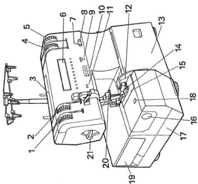
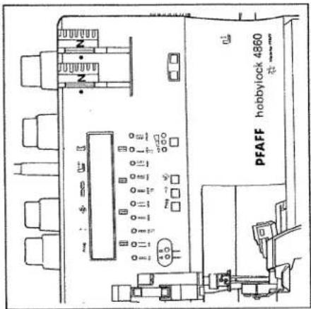
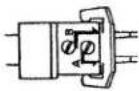
Exterior view of a PFAFF baby washing machine (hobbylock 4860) with control panel and mechanical components (no readable text beyond branding)Instruction manual
You will find the contents on page 4 and 5
Safety rules
For the United Kingdom only
The leads must under no circumstances be connected to the safety-lead terminal I nor to a plug with three pins.
The wires in the mains lead are coloured according to the following code:
Blue: Neutral
Brown:Live
As the colours of the wires in the mains lead of this appearance may not correspond to the colour coding of the terminals in your plug, proceed as follows:
completely replaced.
Immediately. Defective mains leads must be plugs be used. They should be disposed of under no circumstances should cut-off mains with the letter L or coloured red.
The wire which is coloured brown must be contacted to the terminal which is marked with the letter N or coloured black.
The wire which is coloured blue must be con- needed to the terminal which is marked with the letter
Only 3 A spare tuses must be used as appro-
ved by ASTA according to BS 1362 and the
tuse cover must be marked 3 A or with the
corresponding colour code.
The drug must never be used without fuses covers. Spare fuse covers are available from electrical suppliers or the PFAFP agencies.
Please also observe the general safety notes on page 2.
For easier understanding of this instruction manual please fold this or the last page out when reading.
text_image
Technical diagram of a drone with numbered parts for identification and assembly reference.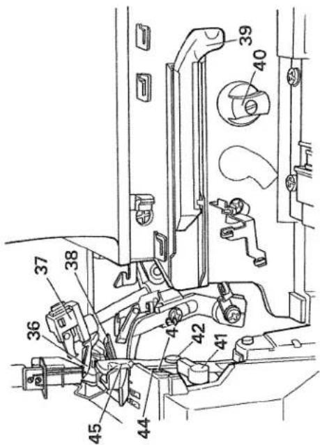
text_image
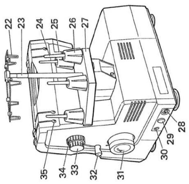
Technical diagram of a mechanical assembly with numbered components for identificationParts of the hobbylock 4860
(1) Upper thread tension - left
(2) Upper thread tension - right
(3) Handle to carry
(4) Looper thread tension - right
(5) Looper thread tension - left
(6) Display
(7) Window for the stitch length (8) Window for the differential fe (9) Key for speed selection
(10) Program key - left
Cursor key - middle
Mod key (right)
(11) LED needle display A, B (12) Knife guard
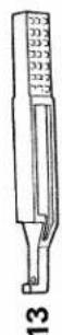
(13) Looper cover
(14) Sewing foot (combination foot) (15) Needle plate
(16) Adjusting knob for seam width (17) Detachable work support
(18) Window for the seam width (19) Accessories box
(20) Needle holder
(21) Lever for the sewing foot pressure
(36) Right overedge looper
(37) Converter
(38) Left overedge looper
(39) Automatic looper threader for the left looper
(40) Knob to disengage upper knife
(41) Lever to disengage needle plate
(42) Screw to secure upper knife
(43) Screw to secure lower knife
(44) Lower knife
(45) Upper knife
Important safety instructions
For the United States only
This sewing machine is designed and manufactured for HOUSEHOLD use only. When you use an electric appliance, the following basic safety precautions should always be adhered to: Read all instructions before using this sewing machine.
DANGER To reduce the risk of electric shock:
- The sewing machine should never be left unattended when plugged in. Always unplug this appliance from the electric outlet immediately after using and before cleaning.
- Always unplug before relamping. Replace bulb with same type rated 15 Watts.
- Do not reach for a sewing machine that has fallen into water. Unplug immediately.
-
Do not place or store a sewing machine where it can fall or be pulled into a tub or sink. Do not place in or drop into water or other liquid. WARNING To reduce the risk of burns, fire, electric shock, or injury to persons:
-
Do not allow to be used as a toy. Great care is necessary when this sewing machine is used by or near children.
- Only use this sewing machine for its intended purpose as described in this manual. Only use attachments recommended by the manufacturer as contained in this manual.
- Never operate this sewing machine if it has a damaged cord or plug, if it is not working properly, if it has been dropped or damaged, or dropped into water. Return the appliance to the nearest authorized dealer or service center for examination, repair, electrical or mechanical adjustment.
-
Never operate the sewing machine with any air openings blocked. Keep ventilation openings of the sewing machine and foot control free from the accumulation of lint, dust, and loose cloth.
-
Never drop or insert anything into any opening.
-
Do not use out of doors.
-
Do not operate where aerosol (spray) products are being used or where oxygen is being administered.
- To disconnect, turn all controls to off („0“) position, then remove plug from socket.
-
Never operate on a soft surface such as a bed or couch where the air openings may be blocked.
-
Do not unplug by pulling on cord. To unplug, hold the plug, not the cord.
-
Keep fingers away from all moving parts. Special care is required around machine needle.
-
Always use the proper needle plate. The wrong plate can cause the needle to break.
- Do not use bent or blunt needles. Only use needles recommended by the manufacturer.
- Do not pull or push fabric while stitching. It may deflect the needle, causing it to break.
-
Switch the sewing machine off („0“) when making any adjustments in the needle area, as threading needle, changing needle, threading bobbin, or changing presser foot, etc.
-
Always unplug sewing machine from the electric outlet when removing covers, lubricating, or when making any other user servicing adjustments mentioned in the instruction manual.
- Hold plug when rewinding into cord reel. Do not allow plug to whip when rewinding. Please also observe the general safety notes on page 2. KEEP THESE INSTRUCTIONS IN A SAFE PLACE

text_image
Warning symbol image with exclamation mark inside a triangleNotes on safety
Notes on safety for domestic sewing
machines according to DIN 57 700, Section 28 or IEC 335, Section 28.
- The user must exercise adequate caution
This sewing machine is a high-quality elec-
tro-mechanical appliance; it is a
machine for supervised use in the
home. It should be operated in such a
way that it is not exposed to: dust, severe
dampness, direct sunlight, static elec-
tricity, heat-producing objects, corro-
theity, heat-producing of give chemicals or liquids.
To permit adequate ventilation the machine
To permit adequate ventilation, the best to be kept unblocked and used on a
must be kept unblocke firm and even surface.
Treatment
Always make ours not to
Always make sure not to damage your machine by knocking or
damage you
dropping it.
Claring
Cleaning
Housing and display:
To clean the housing, use a dry, clean
and soft cloth which is free of fluff. To
remove any stubborn dirt, use a soft
cloth with alcohol or paraffin.
SCHY WITH GREEN, 51
Please Note!
Never use insecticides or che-
mical products such as petrol (gas) or
thin chemicals to clean the housing.
a) In chemical to a chemical
for any damage caused
for any damage caused.
- To avoid the risk of electric shock, do not
open the machine. There are no parts
inside the machine which the user can
repair. This the exclusive responsibility
of our qualified service staff.
- Be sure to use only original PFAFF
parts.
Simple, up-to-date sewing
Congratulations! You have bought a high-quality product that provides unique advantages. Your new hobbylock 4860 can take any material in its stride and will sew, trim and neaten up for you in one operation.
Your PFAFF hobbylock features the very latest in design and technology, and it is just as easy to use as this instruction manual is to follow. If you now take a bit of time to study the instruction manual nothing can go amiss.
It is certainly time well spent, since it is the only way to find out just what your machine can do and put it to full use.
If you have any further questions just ask your PFAFF dealer. He is happy to be of service with any help or advice.
So now let's get started! We wish you many enjoyable hours creating your very own fashion ideas.
| Contents | Page |
| 2 thread overlock stitch | 39, 46 |
| 2 thread overlock | 39 |
| 2 thread rolled/flat hem | 48 |
| 3 thread overlock stitch | 43, 48 |
| 3 thread overlock | 39 |
| 3 thread rolled/flat hem | 48 |
| 4 thread overlock stitch | 39 |
| Accessories | 57 - 68 |
| Accessory box | 10 |
| Automatic threader. | 15, 16 |
| Bead sewing foot | 67 |
| Blindstitch foot | 62 |
| Changing the knife | 70, 71 |
| Changing the light bulb (sewing light) | 72 |
| Changing the needle | 27 |
| Changing the needle plate | 29 |
| Changing the sewing foot | 18 |
| Changing the spool. | 19 |
| Cleaning the knife | 73 |
| Cleaning the needle plate | 72 |
| Converter | 44, 45 |
| Correction of the thread tension | 40 - 42 |
| Cording foot | 66 |
| Detachable work support. | 9 |
| Differential feed | 24, 25, 26 |
| Disengaging the upper knife | 30 |
| Display | 34 |
| Elastic tape sewing foot | 66 |
| Electrical connection | 8, 9 |
| Electronics. | 31 - 36 |
| Entering new data | 36 |
| Foot control | 8 |
| Free arm | 9 |
| Gathering foot | 65 |
| Gimp thread stitching foot | 63 |
| Knob to adjust seam width | 23 |
| Lace sewing foot | 68 |
| LED needle display | 34 |
| Left overedge looper | 15, 16 |
| Looper cover | 12 |
| Lower knife | 73 |
| Main switch | 9 |
| Maintenance and malfunction | 69 - 75 |
| Needle plates N and R | 48 |
| Needle threader | 17 |
| Normal accessories. | 60, 61 |
| Oiling | 73 |
| Overedge needles | 18 |
| Practical sewing | 37 - 55 |
| Problems when sewing | 74, 75 |
| Program chart | 50 - 55 |
| Programming language | 32 |
| Right overedge looper. | 14 |
| Rolled hem | 47, 48 |
| Safety instructions | 1 |
| Securing the seam | 22 |
| Setting the programs | 35 |
| Sewing foot chart | 60 |
| Sewing foot lever | 20 |
| Sewing foot pressure | 30 |
| Sewing test | 21 |
| Special accessories. | 60 - 68 |
| Specifications. | 76 |
| Speed pre-selection | 33 |
| Spool disc | 59 |
| Spool net | 59 |
| Spool stands | 11 |
| Standard thread tension | 38 |
| Stitch length adjusting knob | 24 |
| Taping foot | 61 |
| Technical part | 7 - 30 |
| Thread chart | 49 |
| Thread cutter | 22 |
| Thread unreeling disc | 59 |
| Threading the looper | 14 - 16 |
| Threading the needles. | 18, 19 |
| Threading the thread guides | 13 |
| Upper knife | 70 |
| Upper knife lock. | 30 |
| Waste box. | 12 |
natural_image
Black-and-white illustration of a person lying down with arms outstretched (no text or symbols)Technical part
| Electrical connection | page 8, 9 |
| Detachable work support | page 9 |
| Accessory box | page 10 |
| Spool stands | page 11 |
| Waste box / looper cover | page 12 |
| Threading the thread guides and the looper | page 13 – 16 |
| Threader | page 17 |
| Threading the needles | page 18 |
| Changing a spool when the machine is threaded | page 19 |
| Sewing foot lever | page 20 |
| Sewing test / thread cutter | page 22 |
| Seam width adjusting knob | page 23 |
| Stitch length adjusting knob | page 24 |
| Differential feed | page 24 – 26 |
| Changing the needle, sewing foot and needle plate | page 27 – 29 |
| Fixing the upper knife /sewing foot pressure | page 30 |

natural_image
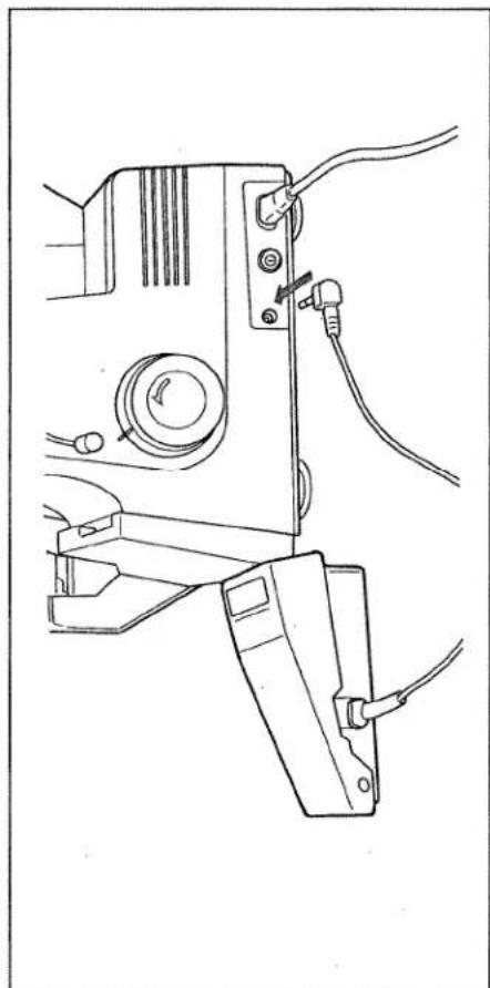
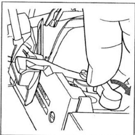
Line drawing of a printer with attached cable and plug, showing no text or symbolsElectrical connection
Connect the mains cord between socket (28) of the sewing machine and the wall socket.
natural_image
Line drawing of a sewing machine with attached cable and power plug (no text or symbols)Connecting the foot control
Connect the plug of the foot control with the connection socket (30) of the sewing machine. The preset area of the sewing speed (see page 33) is regulated by pressing the pedal.
Do not put anything under the pedal.
Caution:
natural_image
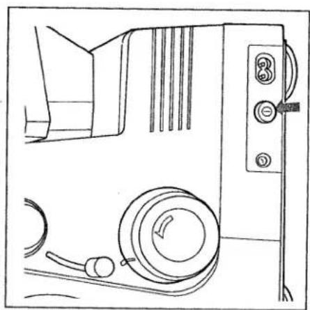
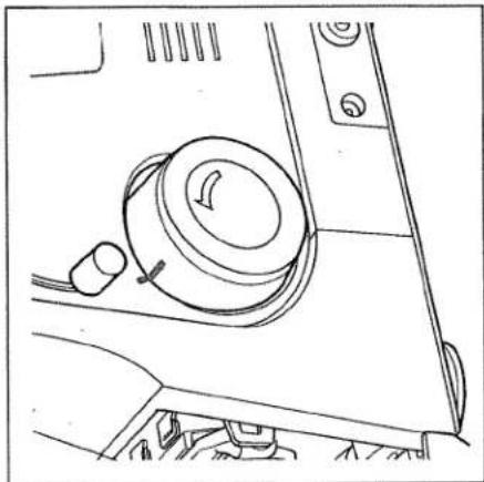
Line drawing of a mechanical device with circular components and control buttons (no text or symbols)Main switch
When the main switch (29) is turned on the sewing light and display (6) is turned up. The machine is now operational.

natural_image
Line drawing of a sewing machine with a cloth cover and clasp mechanism (no text or symbols)
natural_image
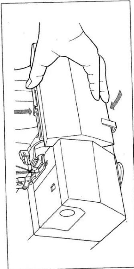
Line drawing of a hand pressing down on a mechanical component (no text or symbols)To remove detachable work support / free arm
The free arm is particularly suited to sew tubular goods without any difficulty. To do so pull the detachable work support (17) to the left. Insert the workpiece in the opposite direction.
natural_image
Line drawing of hands holding a small electronic device with a switch, labeled 'A' (no text or symbols on the device itself)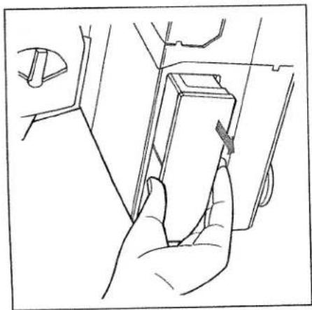
natural_image
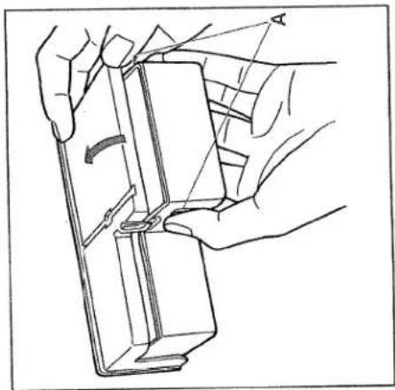
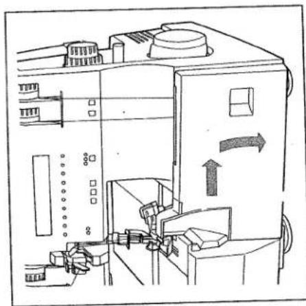
Line drawing of a hand inserting a component into a car compartment (no text or symbols)Accessory box
To open:
To open: Open the accessory box (19) by pressing
the two points „A“.
To remove: Grip in the recess beneath the accessory
box (19) and pull out in the direction of
the arrow.

natural_image
Line drawing of a hand pressing a component on a device (no text or symbols)To insert:
Push the accessory box (19) into the
appropriate opening until it catches. The
words „PFAFF hobbylock“ must be facing
upwards.
natural_image
Line drawing of a hand using a sewing machine to adjust or install a component (no text or symbols visible)Spool stands
Before the spools are attached you must pull the spool stand (27) out fully in the direction of the arrow.

natural_image
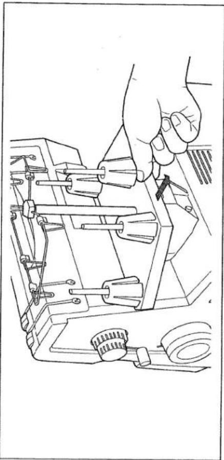
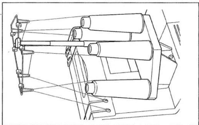
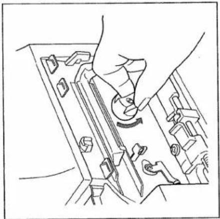
Technical line drawing of a sewing machine with multiple clamps and a hand operating the top section (no text or symbols present)Extend the telescopic thread guide (23) fully.
To assure optimal thread take-up the two upper telescopic extensions must be turned slowly until you hear the ball stops catch in place. When you have finished sewing push in the telescopic thread guide (23) and push the spool stand (27) in towards the machine, with or without the spools, until it catches in place.
natural_image
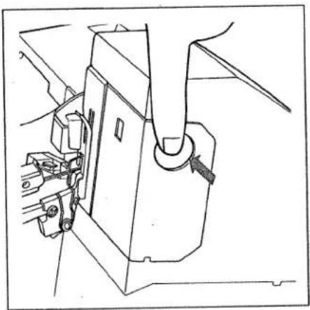
Line drawing of a hand operating a sewing machine with tools and a downward arrow indicating motion (no text or symbols)Waste box
Insert the tabs on the waste box (46) into the notches on the looper cover (13) and press it down against the looper cover until you can hear it catch in place. To take off reverse this process.
natural_image
Technical line drawing of a mechanical device with no visible text or symbolsLooper cover
Push the looper cover (13) to the right until it catches in place and then swivel it down. The individual threading paths as well as the converter setting are illustrated in colour on the inside of the looper cover.
Note: The power supply is interrupted when the looper cover is opened i.e. it is now not possible to sew with the machine. "Close looper cover" appears in the display.
The LEDs also flash the preset speed.
Threading thread guides
Place thread spools on the spool pins (24). For smaller spools we recommend you attach a thread unwinding disc to the spool with the rounded end to the bottom (see the accessories page 66). Thread the thread guides (22) according to colour.

natural_image
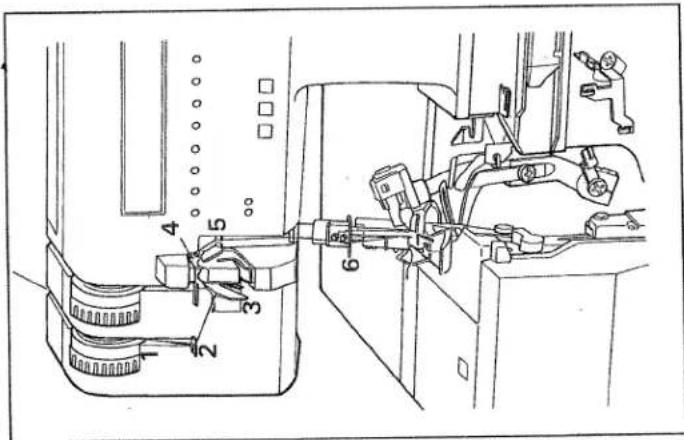
Technical line drawing of a sewing machine with multiple spools and vertical racks (no text or symbols)With both hands pull the thread through the thread guide (35) and the appropriate thread tension (1, 2, 4, 5). Make sure the thread stays in the slot on the back thread guide (35). Set the thread tension to „N” and thread as indicated.
- Right overedge looper (pink)
- Left overedge looper (yellow)
- Right needle (green)
- Left needle (blue)
Note: To achieve top sewing results make sure that the thread is pulled between the tension discs when threading.
natural_image
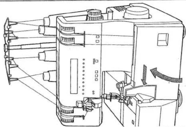
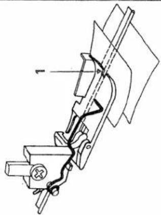
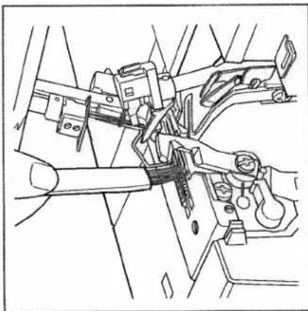
Line drawing of a mechanical device with three spools and suspended arms (no text or symbols)Threading the right overedge looper
The slider on the converter (37) must be in the right hand position B (see page 45). Thread the right overedge looper (36) in the order 1 to 9 and draw the thread to the left under the sewing foot. The thread path is marked in pink.

text_image
Technical diagram of a sewing machine with numbered components for identification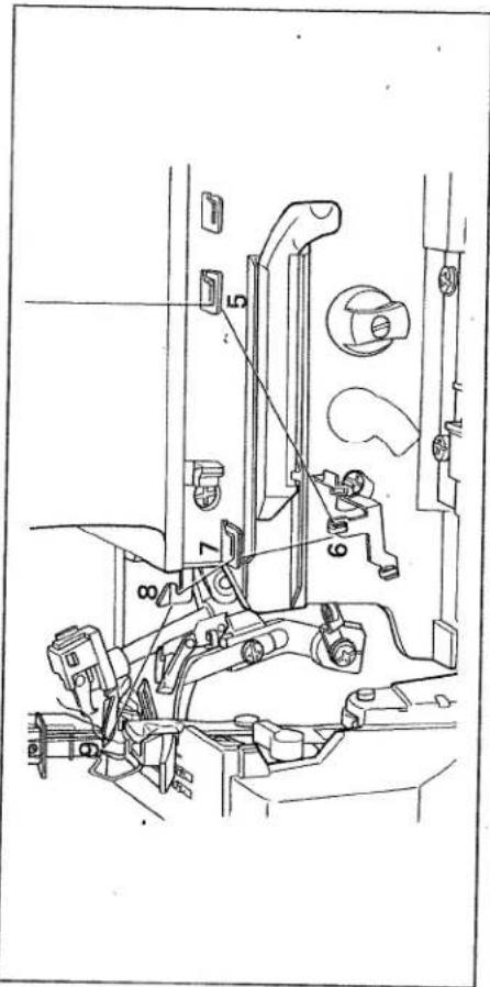
text_image
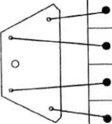
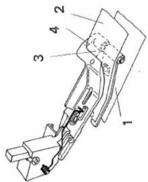
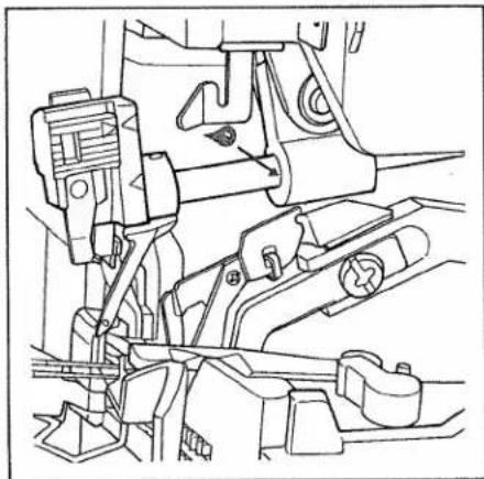
Technical diagram of a mechanical assembly with numbered components for identificationThreading the left overedge looper
-
The marking on the hand wheel must be in line with the marking on the housing.
-
Thread the left overedge looper (38) in the order 1 to 7. Pull the thread from thread guide 7 through the looper eye 8 and pull it a bit with your left hand.
natural_image
Line drawing of a mechanical component with no visible text or symbols
text_image
Technical diagram of a sewing machine with numbered components for identification- Pull the end of the thread slightly and push the slider on the looper threader (39) to the left until it rests in place.

natural_image
Technical line drawing of a mechanical assembly with no visible text or symbols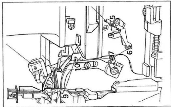
text_image
Technical diagram of a vehicle's internal components with numbered parts for identification- Pull the thread a bit more and at the same time let the slider slowly slide back. The thread is automatically inserted in guide 9.
- With the tweezers thread the thread through thread guide (10) and draw the thread to the left under the sewing foot. The threading path is marked in yellow.
Note:
If the slider on the threader (39) cannot be moved, the marking on the hand wheel is not correctly set.

text_image
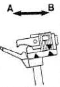
Technical diagram of a vehicle's internal components with numbered parts for identificationNeedle threader (accessory)
Lower the sewing foot with the sewing foot lever (32) and turn the hand wheel (31) until the needle is in its highest position. Place the threader from the accessories (see page 58) with the needle between the two guide lugs B. Draw the thread through slot A on the threader and hold it a bit taut.
Slowly lower the threader behind the
needle until the small hook C passes
through the needle's eye. Draw the
thread from the bottom through hook D
and the thread automatically passes
behind hook C.

text_image
Technical diagram of a mechanical assembly with labeled parts A and B, showing tool path and component alignment.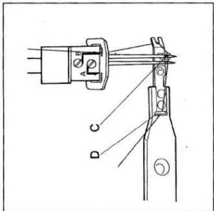
text_image
D C A E
text_image
Technical diagram showing a tool interacting with a mechanical component labeled A and B, with an arrow indicating direction of movement.Draw the threader back away from the needle's eye. You can now pull the end of the thread through the eye to thread the needle.
Threading the needles
Note: When threading the needles make sure that the sewing foot lever (32) is in its highest position. This automatically releases the needle thread tensions and makes it easier to thread the needles.
Threading overedge needle A
Thread the overedge needle A in the order 1 to 6 and draw the thread through the needle's eye 7 with the threader. Draw the thread to the left under the sewing foot. The threading path for needle A in blue (dots).
Threading overedge needle B
Thread the overedge needle B in the order 1 to 6 and draw the thread through the needle's eye 7 with the threader. Draw the thread to the left under the sewing foot. The threading path for needle B in green (dots).
text_image
Technical diagram of a sewing machine with numbered components for identification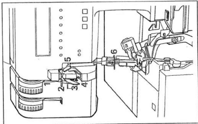
text_image
Technical diagram of a sewing machine with numbered components for identificationChanging a spool when the machine is threaded
Cut the threads off close to the thread spool and put on the new spools. Tie the ends of the old thread and the new thread together. Pull the needle threads out of the needles. Lower the sewing feet. Now pull the threads through until the knots are about six inches through the thread guide before the needles. Cut the knots off and thread the appropriate needles. You can also draw the looper threads straight through the looper eye and to the left under the sewing foot. It is a lot easier to pull the looper threads if you turn to looper tensions (4 and 5) to -5.
Closing the looper cover
When the machine has been threaded you must close the looper cover (13). Note: The power to the machine is cut off if the looper cover is open i.e. it is now impossible to sew. "Close looper cover" appears in the display. The LEDs on the speed selection also flash.
natural_image
Technical line drawing of a sewing machine with no visible text or symbolsSewing foot lever
The sewing foot is raised and lowered with the sewing foot lever (32).

natural_image
Line drawing of a hand using a tool to adjust or install a mechanical component, no text or symbols presentSewing test
When the machine has been threaded, you should sew a test seam. First raise the sewing foot.
Place a fabric remnant under the sewing foot right in front of the needle and lower the foot. With the threads held slightly taut, slowly begin to sew. Since the fabric is automatically fed, you just need to guide the material with your hands (do not push or pull).
Note: Make sure that the threads inter-loop correctly when sewing (thread chain).

natural_image
Technical line drawing of a sewing machine needle assembly (no text or symbols)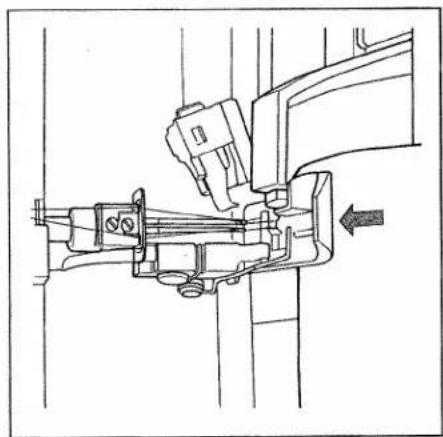
natural_image
Technical line drawing of a sewing machine needle with a hand operating it (no text or symbols present)
natural_image
Line drawing of a sewing machine needle stitching a garment, with hands operating the seam (no text or symbols)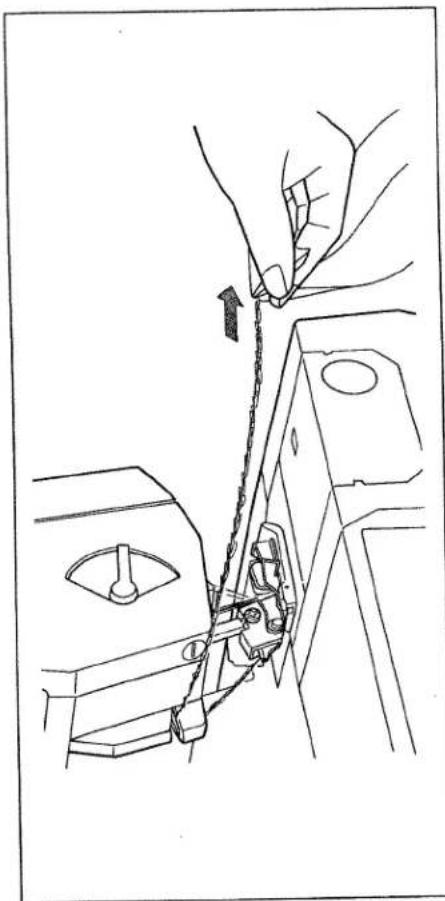
natural_image
Line drawing of a hand operating a sewing machine with chains attached (no text or symbols)Thread cutter
To use the thread cutter (25) you must sew over the end of the seam. Draw the thread chain that results to the front over the thread cutter.

natural_image
Line drawing of a sewing machine needle stitching fabric, no text or symbols presentSecuring the seam
There are various ways of securing the ends of seams:
1. Knot the thread chain
2. With knitwear you can pull the thread chain into the seam with a crochet needle.
3. Sew about 2 inches over the end of the seam. Turn the sewing round and sew back a few stitches in the opposite direction without cutting the thread chain.
Setting the seam width
The seam width adjusting knob (16) is released if it is pressed to the right. You can now set the seam width you require as indicated in the window (18). The range is from 3 to 5 mm and is infinitely variable. The standard setting N is 3,5 mm.
Note: The seam width settings 3 to 5 are just for needle B. If needle A is used the amount that is set is increased by 2,2 mm to 5,2 to 7,2 mm.
When you have set the seam width you require, press the knob to the right until it catches in place, as indicated by the arrow. This prevents the seam width being inadvertently changed while sewing. Note: The upper knife must be locked when sewing very thick fabrics or fabrics with different thicknesses (see page 30).
natural_image
Line drawing of a sewing machine needle and handle mechanism (no text or symbols)
natural_image
Line drawing of a hand operating a rotary knob on a device casing (no text or symbols)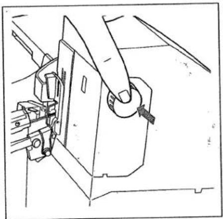
natural_image
Line drawing of a sewing machine needle being sewn, showing the mechanism and component (no text or symbols)
text_image
N 1 1.5 2 2.5 N 3.5 4Setting the stitch length
You can set the required stitch length by turning the stitch length adjusting knob (33). The setting is displayed in the window (7). The range is from 1 to 4mm and is infinitely variable. The standard setting N is 3mm .
Differential feed
The differential feed consists of two feed dogs, one behind the other, that assure that the fabric is fed completely evenly. It prevents the displacement of the two fabric lays. The two feed dogs can be set separately i.e. so that the front dog feeds more than the rear dog or vice versa. This is particularly important when sewing rib knit. The differential feed is set differently depending on the type of fabric. You can see the settings on page 28.
text_image
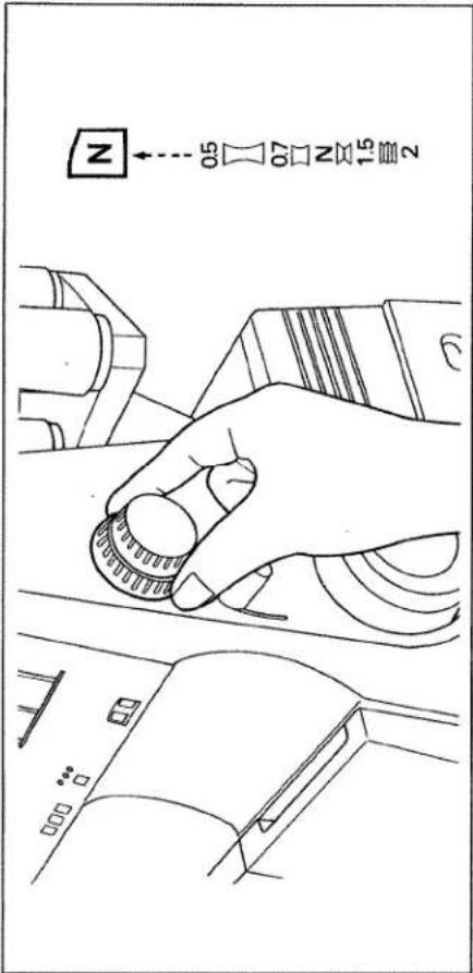
N 0.5 0.7 N 1.5 2Setting the differential feed
You can set the differential feed by turning the adjusting ring (34). The range from 0,5 to 2 is infinitely variable and is indicated in the window (8). The following settings can be set with the knob:
Position 0,5 = front feed dog shorter movement, rear feed dog longer movement
Position N = same movement of feed dogs
Position 1,5 - 2 = front feed dog longer movement, rear feed dog shorter movement
Note: You can also achieve fashionable effects with the differential feed dog: 1. A gathering effect can be achieved when sewing light fabrics with setting 2. 2. A wavelike effect can be achieved for use with rib knit with the setting 0,5.
This table shows possible settings for the differential feed. Sew a test seam to determine the correct setting for your fabric. The differential feed can also be set while sewing.
| Differential-Feed setting | Fig. | Correct seam | Fabric |
| 0,5 - N | 1 | a | nylon, tricot, lining fabrics, satin,poplin and silk |
| N | 2 | c | light cotton and denim,(normal fabrics) |
| 1,5 | 3 | d | jersey, medium cotton, cut-pilefabrics and light knits |
| 1,5 - 2 | 4 | f | heavy knitwear, very elastic fabricsand rib-knit |

natural_image
Close-up of a textured fabric surface with a dark horizontal band at the bottom (no visible text or symbols)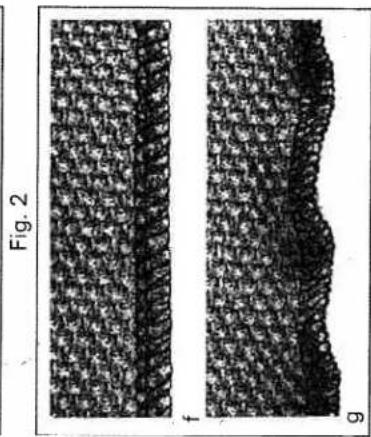
natural_image
Two grayscale microscopic images labeled Fig. 2 and f, showing textured surface patterns with no visible text or symbols.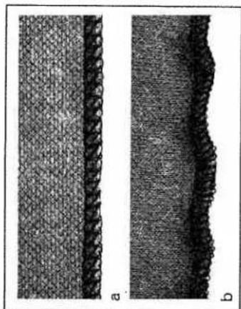
natural_image
Two grayscale images labeled 'a' and 'b' showing textured surfaces with no visible text or symbols.
natural_image
Microscopic images labeled Fig. 1 and d-e showing textured surfaces with no visible text or symbolsChanging the needle
Switch off the main switch.
To remove: Lower the sewing foot and
put the needle in its highest position.
Now push the needle changing aid from
the accessories (see page 58) from below
right up until it catches over the needle.
Loosen set screws (A or B) with the red
screwdriver and pull the needle down to
remove.
To insert: Insert the needle into the hole
E of the needle changing aid, with the flat
needle shank K facing towards the flat
side L of the aid. Insert the needle until it
catches in place in the holder and tighten
the needle set screw. Remove the needle
changing aid.
Note: The following needles are used for
this machine:
System EL X 705 (80 or 90)
If using the usual sewing needles
130/705 H the thread tension must be
increased.
natural_image
Technical line drawing of a mechanical assembly with no visible text or symbols
text_image
L E
natural_image
Two types of writing or drawing tools: a flat tool and a pen-like tool, both with no visible text or symbols.Changing the sewing foot
Switch off the main switch
To remove: Raise the sewing foot with
the sewing foot lever (32) and set the
needle in its highest position. Press the
white lever on the back part of the
sewing foot holder. The sewing foot is
automatically released from its mount
and you can remove it to the left, raising the spring slightly.

natural_image
Technical line drawing of a mechanical assembly with no visible text or symbolsTo insert: Raise the spring slightly and place the sewing foot beneath the sewing foot holder so that when the sewing foot lever (32) is lowered the pin in the foot catches in place in the sewing foot holder.
Check: Please raise the sewing foot lever to check that the foot is properly secured.

natural_image
Line drawing of a hand holding a circular knob on a device casing (no text or symbols)Changing the needle plate
Switch off the main switch
Note: To change the needle plate you must set the needle width adjusting knob (16) to 3 mm.
natural_image
Line drawing of a mechanical assembly with a hand operating a lever (no text or symbols)To remove:
Looper cover open
Raise the sewing foot with the sewing foot lever (32) and set the needle in its highest position. Remove the sewing foot and press down the lever to disengage the needle plate (41). The needle plate (15) is raised out of its mount. Raise the needle plate a little more and remove to the left.
text_image
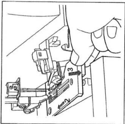
Technical diagram showing a hand operating a mechanical assembly with labeled parts 1, 2, and 3.To attach:
Raise the spring on the sewing foot holder a little and place the needle plate (15) in the guide screw at the back. Press the needle plate down at the front so that you can hear it catch.
Disengaging the upper knife
Note: To disengage the upper knife (45) you must set the seam width adjusting knob (16) to 3 mm.
Lower the knife to the lowest position with the hand wheel. Now turn the knob to disengage the upper knife (40) fully to the left (triangle on O). The knife is disengaged.
Upper knife lock
You can sew absolutely any type of fabric with this machine, regardless of its thickness. For extremely thick fabrics you must tighten the axial lock screw on the upper knife with the large screwdriver from the accessories (see page 58). This prevents the knife from being displaced by the material. Remove the sewing foot and needle plate (see page 28, 29). To sew light fabrics the screw must be loosened by about two turns, so that the knife can again move in an axial (sideways) direction.
Note: The screw for the upper knife must be loosened to change the cutting width.
Adjusting the sewing foot pressure
You can change the sewing foot pressure depending on the thickness of the material with the lever (21).
Position 1 = sewing foot pressure for very thin fabric
Position N = sewing foot pressure for with medium thickness Position 3 = sewing foot pressure for
very thick fabric
natural_image
Line drawing of a hand inserting a component into a device panel (no text or symbols)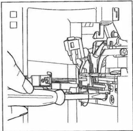
natural_image
Technical line drawing of a mechanical assembly with no visible text or symbols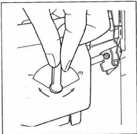
text_image
Technical diagram showing a hand operating a sewing machine with labeled parts 1 and 3, indicating mechanical adjustment or repair.Electronics
To programme language
Speed pre-selection
LED needle display
To select program
To enter new data
text_image
Technical diagram of a sewing machine with labeled parts and directional arrows indicating assembly or positioning.You can choose between the following languages:
Czech, Danish, German, English, Spanish, French, Italian, Dutch, Norwegian, Polish, Finnish, Swedish and Japanese.
To programme language:
Keep both the program key (10 left) and the key (9) for the speed preselection pressed and at the same time switch the machine on.
„cesky“ (Czech) now appears in the display. You can select the language you want by repeatedly pressing the program key (10 left).
By pressing the cursor key (10 middle) once you programme your language.
Each description in the display will now appear in the language that you have selected.
Speed pre-selection
On this machine you can set the maximum speed in three steps with the key (9). By pressing the key (9) you change the maximum speed and one, two or three LEDs light up.
One LED lights up = 0 to max. 500 rpm
Two LEDs light up = 0 to max. 1000rpm
Note:
Each time the machine is switched on it automatically sets a speed of 1000 rpm.

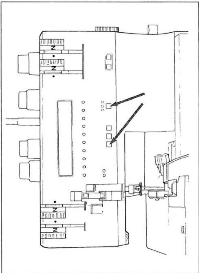
text_image
Technical diagram of a device layout with labeled components and indicators
natural_image
Diagram of a mechanical or electrical component with labeled parts and symbols (no readable text or numbers)Three LEDs light up = 0 to max. 1500rpm

natural_image
Diagram of a mechanical or electrical component with no visible text, numbers, or symbolsLED needle display (A and B)
The LEDs on the needle display (11) show which of the needles A or B have to be inserted for the program you have selected.
text_image
PFAFF hobbylock 4860| Display | |
| This machine has the following 16 programs: | |
| Progr. 1 | 2 thread flatlock narrow |
| Progr. 2 | 2 thread flatlock wide |
| Progr. 3 | 2 thread flat hem |
| Progr. 4 | 3 thread overlock narrow |
| Progr. 5 | 3 thread overlock wide |
| Progr. 6 | 3 thread flat hem |
| Progr. 7 | 3 thread flatlock narrow |
| Progr. 8 | 3 thread flatlock wide |
| Progr. 9 | Reinforced 2 thread overlock |
| Progr. 10 | 4 thread overlock |
| Progr. 11 | Wrapped 2 thread overlock n |
| Progr. 12 | Wrapped 2 thread overlock w |
| Progr. 13 | 2 thread rolled hem |
| Progr. 14 | Wrapped 3 thread overlock m |
| Progr. 15 | Wrapped 3 thread overlock w |
| Progr. 16 | 3 thread rolled hem |
Note:
Beneath this display you will find the LED displays for the 10 most important types of stitch (program 1 to 10).
Select the desired program by pressing the left program key (10). The programs appear in the order 1 - 16. Keep the key pressed and the programs automatically run on.
If the mod key (10 right) is pressed the standard characteristics of the stitch are displayed. Set the machine as indicated in the display.
Symbols above the display:
Prog. = program number
= stitch length
<≦> = seam width
= differential feed
L>●<
= sewing foot pressure
= needle plate
Symbols below the display:
All the symbols under the display refer to the thread tensions. They are from the left to the right.
- left overedge needle (blue) - right overedge needle (green) - right overedge looper (pink) - left overedge looper (yellow)
text_image
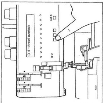
10 4 - thread overlock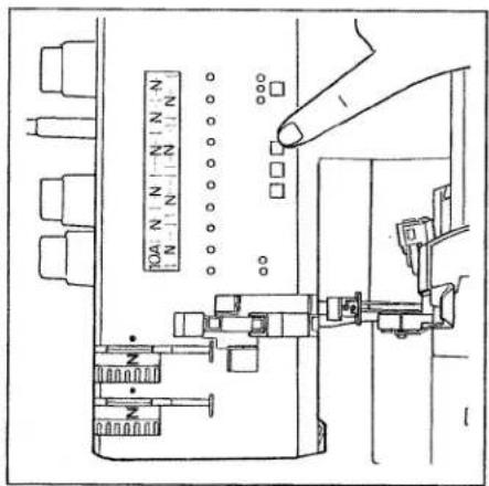
text_image
10A N N -N N-N N N N N N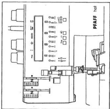
text_image
PFAFF hotEntering new data
This machine has 16 programs. The optimal values are entered as standard settings for each program. You can change all the data from the standard settings in any program and store them. There are three memories (A, B and C) available for each program which appear right behind the program number (e.g. 10 A). Proceed as follows:
-
Select the desired program with the program key (10 left).
-
The standard setting appears in the display when the mod key (10 right) is pressed.
-
If the mod key (10 right) is pressed
again, the letter A appears beside the program number as an indication that you can now enter your own values in memory A. If the mod key (10 right) is pressed again memory B appears and if pressed once more memory C.
-
If the cursor key (10 middle) is pressed, the display for the stitch length appears. You can now alter the stitch length with the program key (10 left).
-
If you wish to alter other settings,
press the cursor key (10 middle) until the setting that is to be changed flashes. You can now set them as required.
- Press the mod key (10 right) to enter the data in memory. Press the mod
key until you come back to the
previously selected memory A, B, or C. All the new data has now been
entered and is retained when the
machine is switched off. If you select your memory again the values that have been entered now flash. They can of course be changed at any time as described.

text_image
10 N N N N N N N N N N N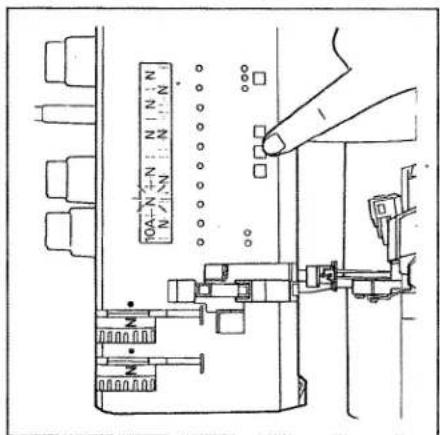
text_image
10A-N+N:N N-N N-N-N-N-N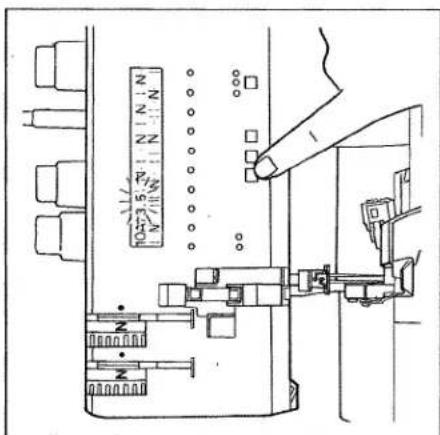
| Setting the standard thread tension | page 38 |
| 3 thread overlock seam | page 39 |
| 4 thread overlock seam | page 39 |
| 2 thread overlock seam | page 39 |
| Correction of thread tensions | page 40 - 42 |
| Converter (2 thread seam) | page 44 - 46 |
| Rolled/flat hem (2 and 3 thread) | page 47, 48 |
| Thread chart | page 49 |
| Program chart | page 50 - 55 |

natural_image
Technical line drawing of a mechanical device with no visible text or symbolsSetting the standard thread tension
Uniform thread tension depends on the type of fabric and the thickness of the thread. The thread tension should be corrected after the thread interloop has been checked (see page 39 to 42).
Turn the values indicated on the thread tension thumbwheels to the corresponding colour symbol.
Prog. 1 or 2
2 thread overlock seam
(narrow or wide) FLATLOCK Converter (see page 44, 45)
Thread tensions:
green or blue = dot yellow = dot
Examples of use:
For sewing and serging all types of fabric, especially suited for stretch fabrics and
for sewing FLATLOCK seams.
Prog. 4 or 5
3 thread overlock seam
(narrow or wide)
Thread tensions:
green or blue = dot
pink = dot
yellow = dot
Examples o
For serging all fabric types.
Prog. 10
4 thread overlock seam
Thread tensions:
blue = dot
green = dot
pink = dot
yellow = dot
Examples of use:
For sewing and serging all types of fabric,
especially suitable for stretch fabrics.
text_image
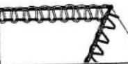
top side overlock stitch, top side overlock stitch, underside underside
text_image
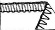
top side overlock stitch, top side overlock stitch, underside underside
text_image
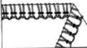
top side overlock stitch top side overlock stitch, underside undersideCorrecting the thread tension:
The tension can be set between -5 and +5. It must be turned either to the - or + range depending on the seam appearance.
Towards + = tighter tension
Towards - = looser tension
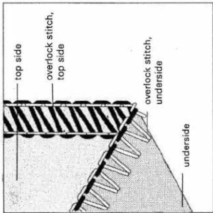
Prog. 4 or 5
3 thread overlock seam
(narrow or wide)
The thread tension of needles B or A is too loose. The green or blue thread tension must be turned towards +.
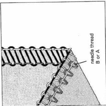
Prog. 4 or 5
3 thread overlock seam (narrow or wide)
The right looper thread is too taut (pink thread tension) or the left looper thread is too loose (yellow thread tension). Both thread tensions must be adjusted accordingly by turning to - or +.
text_image
needle thread B or A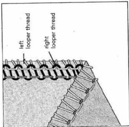
text_image
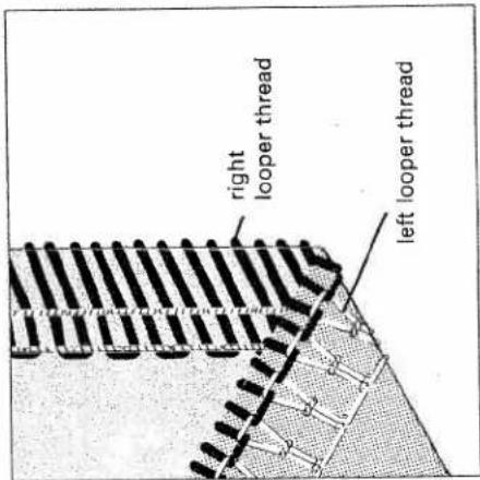
left looper thread right looper threadProg. 4 or 5
3 thread overlock seam
(narrow or wide)
The right looper thread is set too loose (pink tension) or the left looper thread is set too tight (yellow tension). Both thread tensions must be adjusted accordingly by turning to + or -.

text_image
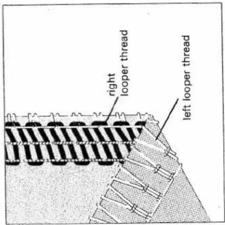
right looper thread left looper threadProg. 10
4 thread overlock seam
The left looper thread is set too tight
(yellow tension) or the right looper
thread is set too loose (pink tension).
Both thread tensions must be adjusted
accordingly by turning either to - or +.
text_image
right looper thread left looper threadProg. 10
4 thread overlock seam
The left looper thread is set too loose
(yellow tension) or the right looper
thread is too tight (pink tension). Both
thread tensions must be adjusted accord-
ingly by turning either to + or -.
text_image
right looper thread left looper threadProg. 10
4 thread overlock seam
The thread tension on needle B is too loose. The green tension must be turned to +.
Prog. 10
4 thread overlock seam
The thread tension of needle A is too loose. The blue tension must be turned to +.

text_image
needle thread B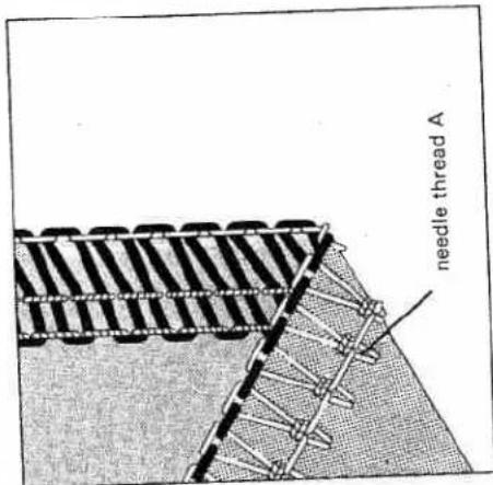
text_image
needle thread AProg. 4 or 5
| 3 thread overlock seam (narrow or wide) |
| The 3 thread overlock seam is sewn with two looper threads and one needle thread (needle change page 27). |
| The set seam widths 3 to 5 mm in the window (18) only apply to needle B. |
| If needle A is used, the setting is increased by 2,2 mm (seam width 5,2 to 7,2 mm). |
| 3 thread overlock seam | |
| Needle A | Needle B |
Standard needle width N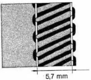 | Standard needle width N |
| Needle width | Needle width |
| min. 5,2 mm, max. 7,2 mm | min. 3 mm max. 5 mm |
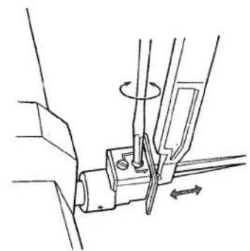
Converter
A serging seam is generally sewn with 3 threads. If you connect the converter you can dispense with one thread i.e. you just continue to sew with 2 threads and thus save a lot of thread. Wherever a 2 thread seam is enough i.e. for elastic materials and materials that hardly fray, you can still make neat edges with less thread. You can also make very effective fancy seams with the converter using mercerized cotton.
All seams that are sewn with the converter (37) are only sewn with the left looper thread (yellow thread path) and with one needle thread. Exception: Prog. 9 is sewn with two needle threads and the left looper thread.
To switch on the converter
Turn the hand wheel until the right over-edge looper (36) is situated to the right of the needle.
To use the converter (37) you must cut off the right looper thread and pull it out of the looper eye.

natural_image
Technical line drawing of a mechanical clamp or tool with a pen inserted (no text or symbols)
natural_image
Technical line drawing of a mechanical device with scissors and cutting tool (no text or symbols)The left hand thread that runs over the right looper must be pulled over the point of the right looper in the direction of the arrow as in this illustration.
Push the slide of the converter to the left until the triangles are in line. The point of the slide catches into the eye of the looper (Fig A).
Converter switched on - position A
Converter switched off - position B
To switch the converter off
Turn the hand wheel slowly until the left hand looper thread jumps from the point of the right looper. Switch the converter (37) off in this position (position B). Thread the right looper (see page 14).

natural_image
Technical line drawing of a mechanical clamp or bracket assembly (no text or symbols)
text_image
Technical diagram of a mechanical tool with an inset showing a labeled component 'A' and angle 'θ'
text_image
A B2 thread overlock seam with converter
Standard seam width with needle A = 5,7 mm (range from 5,2 - 7,2 mm) Standard seam width with needle B = 3,5 mm (range from 3 - 5 mm)
Progr. 1 or 2
2 thread overlock seam (narrow or wide) FLATLOCK
This illustration shows the 2 thread over-lock seam with the thread tensions correctly set.
Ways of correcting the thread tensions
Prog. 1 or 2
2 thread overlock seam (narrow and
wide) FLATLOCK
Looper thread E is set too tight (yellow tension) or needle thread F is too loose
(green or blue tension). The two thread
tensions must be turned accordingly
to + or -.
The looper thread E is set too loose (yellow tension) or the needle thread F is too tight (green or blue tension). The two thread tensions must be turned accordingly either to + or -.

text_image
underside E F top side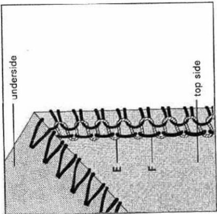
text_image
underside E F top side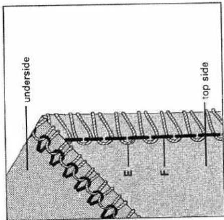
text_image
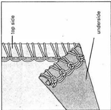
underside E F top sideProg. 3, 6, 13 or 16
Rolled/flat hem
A rolled/flat hem is used for light, thin fabrics and also creates a decorative edge. It is a very simple way to add a professional touch to cloths, scarves and valance. To do so just convert the machine as indicated in the display.
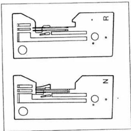
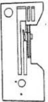
The rolled hem can only be sewn with the needle B and you must also replace the needle plate N with the rolled hem plate R (see page 28, 29).
The best suited threads are textured thread (bulk thread) as well
The best suited threads are textured thread (bulk the Only textured thread should be used for the looper.
Prog. 6
3 thread flat hem

text_image
top side undersideProg. 16
3 thread rolled hem
text_image
top side undersideNeedle plates N and R
The needle plate R must be used for all rolled hems.
natural_image
Two schematic diagrams of electronic components with labeled pins (N and R), no readable text or symbols present.Prog. 3
2 thread flat hem
The amount of thread used for the 2 thread flat hem is smaller and the sear seems finer. The converter must be switched on for this flat hem (see pages 44, 45).

text_image
top side undersideProg. 13
2 thread rolled hem
The converter must be switched on fo this rolled hem (see pages 44, 45).

text_image
top side underside| Thread chart for the 2,3 and 4 thread overlock seam | ||
| Fabric weight | Thread | Stitch length |
| Light fabrics:organdy, fine tricot,taffeta, silk,lining fabric | cotton no. 80 - 100silk no. 80 - 100synthetic thread no. 70 - 140 | 2,0 - 4,0 mm |
| Medium-weight fabrics:cotton, tricot,linen, children's fabrics | cotton no. 60 - 100silk no. 50 - 100synthetic thread no. 70 - 140 | 2,0 - 4,0 mm |
| Heavy fabrics:tweed, jacket cloth,denim, heavy cloth | cotton no. 40 - 60silk no. 40 - 60synthetic thread no. 70 - 140 | 2,0 - 4,0 mm |
| Knits: | cotton no. 40 - 60silk no. 40 - 60synthetic thread no. 70 - 140 | 2,0 - 4,0 mm |
| 2 or 3 threadrolled hem | polyester thread no. 120 - 140texturedthread(bulky thread) | 1,0 - 2,0 mm |
Program chart
The values for thread tension, stitch length, needle thickness and the differential feed settings are basic settings and must be altered or corrected depending on the type of fabric, fabric thickness and thread.
The differential feed setting depends on the type of fabric (see page 26). All the possible types of stitch and the settings that are necessary are listed in this chart.
| Program no.: Stitch type | Material | Needle thread tension | Looper thread tension | Sewing foot pressure | Stitch length | ||
| blue | green | pink | yellow | ||||
| Prog. 12 thread flatlock seam(narrow) | light | -3 | +1 | 1-N | N | ||
| medium | -3 | +1 | N | ||||
| heavy | -3 | +1 | N-3 | ||||
| Prog. 22 thread flatlock seam(wide) | light | -1.5 | +1 | 1-N | N | ||
| medium | -1.5 | +1 | N | ||||
| heavy | -1.5 | +1 | N-3 | ||||
| Prog. 32 thread flat hem | light | -2 | +1 | 1-N | 1 to 1,5 | ||
| medium | -2 | +1 | N | ||||
| heavy | |||||||
Note:
This information about the thread spools, position of the looper disengaging lever and the converter position is only to be found in this chart (not in the display).
| Thread spool | Needle | Needle plate | Differential feed setting | Slide position of converter | |||||
 |  |  |  |  | |||||
| A | B | A | B | ||||||
| ● | ● | 9014 | N | N | ● | ||||
| ● | ● | 9014 | N | N | ● | ||||
| ● | ● | 8012 | R | N | ● | ||||
| Program no.: Stitch type | Material | Needle thread tension | Looper thread tension | Sewing foot pressure | Stitch length | ||
 blue blue |  green green |  pink pink |  yellow yellow |  |  | ||
| Prog. 43 thread overlock seam(narrow) | light | N | N | N | 1 - N | N | |
| medium | N | N | N | N | |||
 | heavy | N | N | N | N - 3 | ||
| Prog. 53 thread overlock seam(wide) | light | N | N | N | 1 - N | N | |
| medium | N | N | N | N | |||
 | heavy | N | N | N | N - 3 | ||
| Prog. 63 thread flat hem | light | N | + 1 | N | 1 - N | 1 to 1.5 | |
| medium | N | + 1 | N | N | |||
 | heavy | ||||||
| Prog. 73 thread decorative seam(narrow) flatlock | light | -3 | + 1 | + 4 | 1 - N | N | |
| medium | -3 | + 1 | + 4 | N | |||
 | heavy | -3 | + 1 | + 4 | N - 3 | ||
| Prog. 83 thread decorative seam(wide) flatlock | light | -1.5 | +0.5 | + 4 | 1 - N | N | |
| medium | -1.5 | +0.5 | + 4 | N | |||
 | heavy | -1.5 | +0.5 | + 4 | N - 3 | ||
| Prog. 9reinforced 2 threadoverlock seam | light | N | N | -1 | 1 - N | N | |
| medium | N | N | -1 | N | |||
 | heavy | N | N | -1 | N - 3 | ||
| Thread spool | Needle | Needle plate | Differential feed setting | 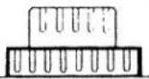 | Slidesetting ofconverter | |||||
 | A | B | N | N | N | N | ● | ● | ||
| A | B | |||||||||
 | 9014 | N | N | N | ● | ● | ● | |||
| 9014 | 8012 | N | N | ● | ||||||
| ● | ● | ● | ● | ● | ● | ● | ||||
| ● | ● | ● | ● | ● | ● | ● | ||||
| ● | ● | ● | ● | ● | ● | ● | ||||
| ● | ● | ● | ● | ● | ● | ● | ||||
| ● | ● | ● | ● | ● | ● | ● | ||||
| ● | ● | ● | ● | ● | ● | 9014 | ||||
| ● | ● | ● | ● | ● | ● | 9014 | ||||
| ● | ● | ● | ● | ● | ● | 9014 | ||||
| Program no.: Stitch type | Material | Needle thread tension | Looper thread tension | Sewing foot pressure | Stitch length | |||||
 blue blue |  green green | 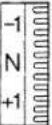 pink pink |  yellow yellow |  | 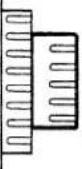 . . | |||||
| Prog. 104 thread overlock seam | light | -0.5 | -0.5 | N | N | 1-N | N | |||
 | medium | N | N | N | N | N | ||||
| heavy | N | N | N | N | N-3 | |||||
| Prog. 11Wrapped 2 thread overlock seam (narrow) | light | N | -1 | 1-N | N | |||||
| medium | N | -1 | N | |||||||
 | heavy | N | -1 | N-3 | ||||||
| Prog. 12Wrapped 2 thread overlock seam (wide) | light | N | -1 | 1-N | N | |||||
| medium | N | -1 | N | |||||||
 | heavy | N | -1 | N-3 | ||||||
| Prog. 132 thread rolled hem | light | N | -1 | 1-N | 1 to 1.5 | |||||
| medium | N | -1 | N | |||||||
 | heavy | |||||||||
| Prog. 14Wrapped 3 thread overlock seam (narrow) | light | N | -5 | +3.5 | 1-N | N | ||||
| medium | N | -5 | +3.5 | N | ||||||
 | heavy | N | -5 | +3.5 | N-3 | |||||
| Prog. 15Wrapped 3 thread overlock seam (wide) | light | N | -5 | +3.5 | 1-N | N | ||||
| medium | N | -5 | +3.5 | N | ||||||
 | heavy | N | -5 | +3.5 | N-3 | |||||
| Prog. 163 thread rolled hem | light | N | N | +3 | 1-N | 1 to 1.5 | ||||
| medium | N | N | +3 | N | ||||||
 | heavy | |||||||||
| Thread spool | Needle | Needle plate | Differential feed setting | Slide setting of converter |  | ||||||
| A | B | ||||||||||
 |  |  |  | ||||||||
| N | N | ||||||||||
| N | N | ||||||||||
| ● | ● | 9014 | 9014 | N | N | N | ● | ||||
| ● | ● | 9014 | 9014 | N | N | N | ● | ||||
| ● | ● | 9014 | 9014 | R | N | N | ● | ||||
| ● | ● | 9014 | 9014 | N | N | N | ● | ||||
| ● | ● | 9014 | 9014 | N | N | N | ● | ||||
| ● | ● | 9014 | 9014 | R | N | N | ● | ||||
natural_image
Black-and-white photo of a person in a hooded garment holding a phone, with no visible text or symbols.Accessories
page 58, 59 page 59–68
Normal accessories Special accessories
Screwdriver (small)
Screwdriver (big)
Lint brush
Tweezers
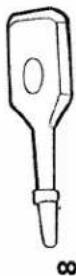
5 Upper knife
Thread unreeling disc (4 x)
7 Needles
8 Sewing machine oil
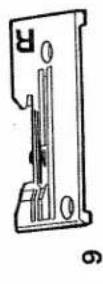
9 Rolled/flat hem needle plate R
0 Thread spool net (4 x)
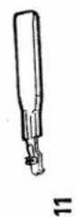
1 Needle threader
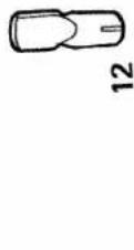
12 Tool for changing the light bulb
13 Needle changing aid


Thread spool net
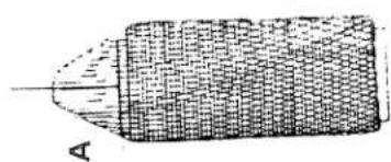
The thread spool net from the accessories (see page 58) is particularly useful as it prevents synthetic threads from unravelling so easily and slipping off the spool (Fig A).
spool (Fig A).
Thread unreeling disc
The thread unreeling disc from the accessories (see page 58) is used for smaller thread spools. Remove the thread spool centering pieces from the thread reel pin and put on the thread spools. Place the thread unreeling disc on the bottom of the reel pin with the rounded end C to the bottom as in fig. B.
Reel disc (special accessories)
The reel disc D is helpful when using large thread spools (5.000 - 10.000) Place the thread spool centering piece (26) upside-down on the reel pin (24) illustrated.
The reel disc prevents the loops of synthetic threads from slipping down and ensures that the thread runs smoothly.
natural_image
Illustration of a cylindrical object with textured surface and labeled point A (no text or symbols on the object itself)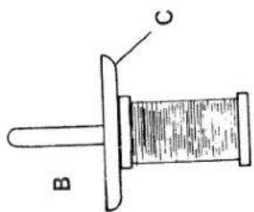
text_image
B C
natural_image
Illustration of a mechanical device with a conical spool and base mount (no text or symbols)Chart for the combination of sewing feet and needle plates
| Sewing foot | Needle plate | Accessory | Part no. |
| Combination foot | N | normal accessory | 29-924 993-71/287 |
| Combination foot | R | normal accessory | 29-924 993-71/287 |
| Taping foot | N | special accessory | 29-924 993-71/295 |
| Blindstitch foot | N | special accessory | 29-924 993-71/291 |
| Gimp thread sewing foot | R | special accessory | 29-924 993-71/294 |
| Elastic tape sewing foot | N | special accessory | 29-924 993-71/292 |
| Gathering foot | N | special accessory | 29-924 993-71/293 |
| Cording foot | N | special accessory | 29-924 993-71/298 |
| Bead sewing foot | R | special accessory | 29-924 993-71/296 |
| Lace sewing foot | R | special accessory | 29-924 993-71/297 |
Taping foot
This special sewing foot is for sewing on tapes to prevent stretch materials (knit-wear) from stretching.
Preparing the machine:
| Program: | 4 or 5 depending on width of tape |
| Stitch length: | N |
| Stitch width: | 3 - 5 (adjustable for a tape width of 4 - 9 mm) |
Differential setting: Sewing foo

natural_image
Close-up of a textured fabric with a vertical seam or edge, showing no visible text or symbols.Inserting the tape:
-
Set the needle at highest point.
-
Raise sewing foot and place tape in guides 1 from the right.
-
Push tape to right stop with the slide 2.
-
Depending on the width of the tape, adjust its position in relation to the needle with adjusting screw 3.
- Insert fabric and sew a test seam.

text_image
Technical diagram of a mechanical device with numbered components labeled 1, 2, and 3Blindstitch sewing foot
Blindstitch is ideal for skirt and trouser seams and wherever the seam should not be visible. The hem is trimmed, serged and sewn in one operation.
Preparation of the machine:
Program: 4 Stitch length: 4 Stitch width: N
setting: N
pressure: N
Needle plate: normal needle plate N Thread tension: see display
. (press mod key) Sewing foot: blindstitch foot
Upper knife: switch on
Sewing:
- Before sewing cut 2 cm off hem part
-
This prevents displacement of the seam.
-
Place the prepared hem under the sewing foot so that the folded hem part 3 is under the edge guide 2. The crease line 4 of the outer fabric must run along the edge of guide 2.
-
The needle penetration in the outer fabric is regulated as follows: Loosen the adjusting screw 1 and adjust the edge guide 2 so that only one thread of the outer fabric is caught by the needle.

text_image
Technical diagram of a sewing machine with numbered parts labeled 1 to 4
natural_image
Close-up of a textured surface with a diagonal white line overlay (no text or symbols)Gimp thread sewing foot
This special sewing foot is used to sew in gimp threads (cords, synthetic threads) up to a thickness of 1.0 mm. This produces an undulating or stiffer hem (e.g. on wedding dresses and valance).
Preparing the machine:
13 (switch converter
1.0 to 1.5
3 to 4
Differential
setting: Sewing foot
N
Needle plate: rolled seam needle
plate R
Thread tension: see display
(press mod key)
gimp thread sev
engaged
Inserting the gimp thread
- Raise the sewing foot and set the
needle in its highest position.
-
Place the fabric under the sewing foot.
-
Thread gimp thread (cord) through the
hole 1 and then place it in guide 2 of
the sewing foot shoe.
- Sew a test seam.

text_image
Technical diagram of a mechanical assembly with labeled parts 1 and 2
natural_image
Close-up of a textured surface with a vertical seam or edge, no visible text or symbols
natural_image
Close-up of a textured fabric with two vertical seam patterns (no text or symbols)Elastic tape sewing foot
| This special sewing foot is for sewing on elastic tape in one operation at the same time as trimming, serging and - due to the contraction of the elastic tape - gathering. |
Preparing the machine:
| Program: | 4, 5 or 10 depending on width of tape |
| Stitch length: | 4 |
| Stitch width: | 4 to 4,5 |
| Differential setting: | N |
| Sewing foot pressure: | N or 3 |
| Needle plate: | normal needle plate N |
| Thread tension: | see display (press mod key) |
| Sewing foot: | elastic tape sewing foot |
| Upper knife: | engaged |
Inserting elastic tape:
- Loosen the screw (2) so that the brake (1) at the opening is opened about 1,5 to 2 mm.
- Insert elastic tape (3) and draw it back under the foot.
- Tighten the brake (1) again with screw (2). The lower the screw (2) is tightened up, the greater the pressure of the brake (1) on the elastic tape and the greater the gathering effect.
Note:
When the sewing foot is raised the elastic tape should be drawn through the brake (1) against a slight resistance.

text_image
Technical diagram of a mechanical assembly with numbered components and directional arrows indicating motion or force
natural_image
Close-up of a textured fabric with diagonal seam and visible stitching (no text or symbols)Gathering foot
| This special gathering foot is for sewing two fabrics together and gathering the bottom ply in one operation. |
Preparing the machine:
| Program: | 10 |
| Stitch length: | N |
| Stitch width: | N |
| Differential setting: | 2 |
| Sewing foot pressure: | N or 3 |
| Needle plate: | normal needle plate N |
| Thread tension: | see display (press mod key) |
| Sewing foot: | gathering foot |
| Upper knife: | engaged |
Inserting the fabrics:
-
Raise the sewing foot and set the needle in its highest position.
-
Insert the bottom ply of fabric 1 between the needle plate and the gathering foot up to the upper knife.
-
Place the upper ply of fabric 2 flush with the lower ply (right side to right side) right up to the edge 4 of openi 3.
-
Always sew a test seam to decide the desired gathering effect with the differential feed.
text_image
Technical diagram of a mechanical assembly with numbered components labeled 1 to 4
text_image
Cropped image showing vertical Chinese characters on a dark textured background, likely from a sign or label.Cording foot
This special sewing foot is for sewing a cording tape between two fabric plies in one operation.
| Preparing the machine: | |
| Program: | 10 |
| Stitch length: | N |
| Stitch width: | 3 - 5 |
| Differential setting: | N |
| Sewing foot pressure: | N or 3 |
| Needle plate: | normal needle plate N |
| Thread tension: | see display (press mod key) |
| Sewing foot: | cording foot |
| Upper knife: | engaged |
Inserting the fabric plies:
-
Raise the sewing foot and set the needle in its highest position.
-
Insert the bottom, ply, cording tape and top ply together flush (right side to right side) under the cording foot up to the upper knife. The cording (piping) must be placed in guide 1.
-
Lower the sewing foot and sew a test seam.
natural_image
Technical line drawing of a mechanical assembly with no visible text or symbols
natural_image
Two vertical dark textured surfaces with a white horizontal line dividing them (no text or symbols)sewing foot
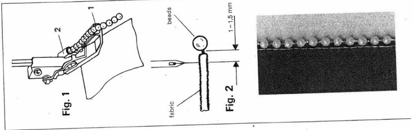
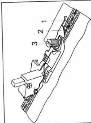
| This special sewing foot is for sewing on beads, sequins, strass bands, lead and ordinary cords. These operations are carried out with one needle only. |
Preparing the machine:
| Program: | 4 (for small beads) |
| 5 (for larger beads) | |
| Stitch length: | 3 to 4 |
| Stitch width: | N to 5 |
| Differential setting: | N |
| Sewing foot pressure: | 1 or N |
| Needle plate: | rolled hem needle plate R |
| Thread tension: | see display (press mod key) |
| Sewing foot: | bead sewing foot |
| Upper knife: | optionally disengag or not |
Sewing:
-
Raise the sewing foot and set the needle in its highest position.
-
Slide the bead tape through guide 1 and 2 to the back of the foot foot (fig. 1).
- You can sew with or without the upper knife in all the seam width settings. Guide the fabric along the right hand sewing edge.
- The needle should penetrate 1 to 1,5 mm along the edge of the fabric (fig. 2).
Note:
If the bead is sewn onto the fabric edge, the left needle must be used (disengage upper knife).
Lace sewing foot
| This special sewing foot is used for sewing lace or borders together or onto the workpiece. |
Preparing the machine:
| Program: | 4 |
| Stitch length: | 1,5 to 2,0 |
| Stitch width: | N |
| Differential setting: | N |
| Sewing foot pressure: | 1 or N |
| Needle plate: | rolled hem |
plate R
Thread tension: see display
(press mod key)
lace sewing foot
Upper knife: optionally disengaged
or not
Sewing on lace:
1. Raise the sewing foot and set needle
in highest position.
| 2. Loosen screw 3 and adjust guide 2 so that when sewing the needle penetrates right at the edge of the lace (and the fabric underneath). Tighten screw 3. |
| 3. When sewing the lace onto the fabric it must simply be run through guide 2 along edge guide 1 (engage upper knife). |
- If the fabric underneath is not to be
trimmed when the lace is sewn on.
both the lacc and the fabric must be
both the face and the fabric must be
guided flush along edge guide (upper knife disengaged). - Always sew a test seam.
text_image
Technical diagram of a mechanical assembly with numbered components labeled 1, 2, and 3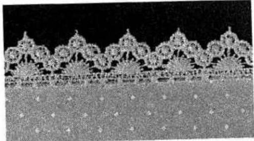
natural_image
Close-up of a decorative lace pattern with floral motifs, no visible text or symbols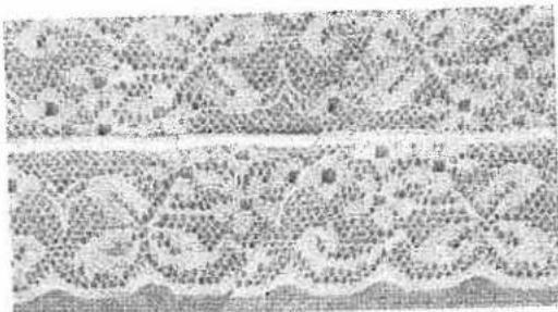
natural_image
Microscopic view of cellular or tissue structures with no visible text or symbolsMaintenance and malfunction
page 70, 71 page 72 page 72 page 73 page 73 page 74, 75 page 76
Changing the knives Changing the light bulb Cleaning the needle plate Cleaning the knives Oiling the machine Sewing problems Specifications
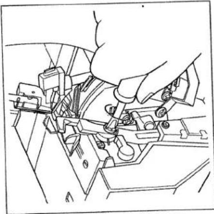
Changing the upper knife
Switch main switch off
To remove: Take out the upper knife
retaining screw (42) with the large
screwdriver from the accessories (see 58) and remove the upper knife.
page (45).
To insert: Insert the new upper knife (45)
and tighten-its retaining screw loosely.
Turn the hand wheel until the upper knife
is in its lowest position.
natural_image
Line drawing of a hand operating a mechanical device with no visible text or symbols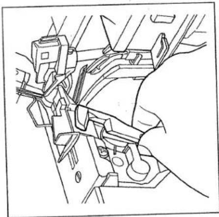
natural_image
Technical line drawing of a mechanical assembly with no visible text or symbolsIn this position the front edge of the
upper knife must be 0,5 to 1,0 mm
lower that the cutting edge of the lower
knife. When the upper knife has been
fully adjusted, you can tighten up its
retaining screw.
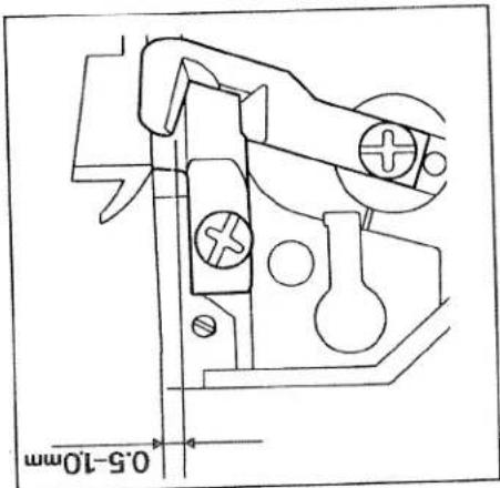
text_image
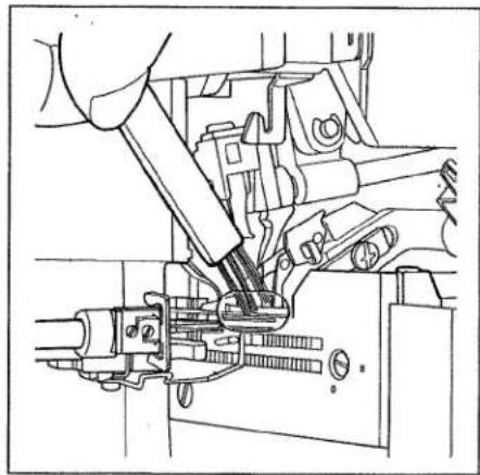
0.5-10mmChanging the lower knife
Switch main switch off
To remove: Set the seam width adjusting knob (16) to 3. Remove the sewing foot as well as the needle plate (see page 28, 29). Raise the needles to their highest position and disengage the upper knife (see page 30). Undo the lower knife retaining screw (43) with the large screwdriver from the accessories (see page 58) and remove the screw, pressure plate and lower knife.

natural_image
Technical line drawing of a mechanical assembly with no visible text or symbolsTo insert: Slide the new lower knife (44)
between the lower knife holder and the upper knife. Place the pressure plate on the hole in the lower knife so that the longer part with the slanted corner is pointing backwards to the machine. Secure the lower knife and the pressure plate with the retaining screw. Insert the needle plate. Bring the cutting edge of the lower knife to the same level as the needle plate. Now tighten up the retaining screw.

natural_image
Pure mechanical component diagram without any text, numbers, or symbolsChanging the light bulb
Switch main switch off
To remove: With the tool from the accessories (see page 58) press the light bulb right into its holder. At the same time twist the bulb with half a turn, anticlockwise and remove it.

natural_image
Technical line drawing of a mechanical assembly with a hand operating a component (no text or symbols present)To insert: Insert the light bulb in the holder with the special tool and twist it until the pins on the bulb catch in place.
Now press the bulb right into the holder, twisting it clockwise until it is securely fixed. Note: The maximum power of the bulb is 5 watt.
Cleaning the needle plate Switch the mainswitch off
Disengage the upper knife (see page 30). Set largest stitch width. Clean the marked area carefully using the brush from the accessories.
natural_image
Technical line drawing of a mechanical assembly with no visible text or symbols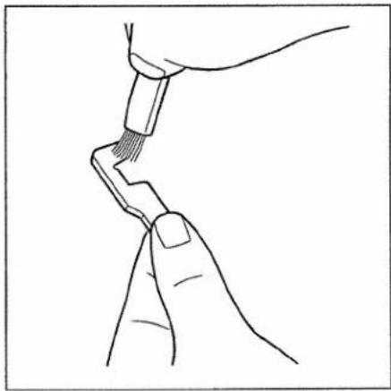
natural_image
Line drawing of two hands holding a tool, no text or symbols presentYou can now remove the upper knife (45) and clean the lint off the upper and lower knife with the brush from the accessories (see page 58).

natural_image
Technical line drawing of a mechanical assembly with no visible text or symbolsOiling the machine
Before using your machine you should make a habit of lightly oiling the marked points with the oil from the accessories (see page 66). One or two drops of PFAFF sewing machine oil are enough. All the other parts are made of a special material and do not need to be oiled.
natural_image
Technical line drawing of a mechanical assembly with no visible text or symbolsCleaning the knife
Switch the main switch off
Take out the upper knife retaining screw (42) with the screwdriver supplied.
natural_image
Technical line drawing of a mechanical assembly with no visible text or symbolsSewing problems and their solutions
The machine was developed for the simplest operation possible. There are no complicated settings. It is however possible that the following problems arise as a result of small errors in the settings and operation. These problems can be easily solved if you follow these instructions.
| Problem | Cause | Solution |
| Needle breakage | The needle was bent or the point damaged.The needle was not properly inserted.The fabric was pulled too forcefully. | Insert new needle (see page 27).Insert needle properly (see page 27).Do not pull the fabric when sewing. |
| Thread breaks | Incorrect threading.The thread got caught.Thread tension is too tight.The needle was not properly inserted.The wrong needle was used. | Thread properly (see page 13 – 18).Check if you have caught the thread on the spool stands etc.Correct the tension.(see page 40 – 41 and 46).Insert needle correctly.(see page 27).Use needle system EL X 705 |
| Skipping stitches | The needle is bent or the point damaged.The needle was not properly inserted.The wrong needle was used.Incorrectly threaded. | Insert new needle (see page 27)Insert the needle correctly (see page 27).Use needle system EL X 705 Thread correctly (see page 13 – 18). |
| Stitch formation faulty | Thread tensions wrongly set. | Re-set thread tensions (see page 40 – 41 and 46). |
| 3 or 4 thread over-lock seam is irregular.The right looper thread is not sewn. | The converter is in its left position A (see page 45) | The converter must be set in its right position B (see page 45). |
| Problem | Cause | Solution |
| The machine does not operate although the main switch is switched on. | The electric power has been cut. | Close the looper cover (see page 12). |
| The fabric is not trimmed neatly. | Lint between the upper and lower knife.The lower knife is blunt. | Clean the knife(see page 73).Change lower knife(see page 71). |
| Gathering of the seam. | The thread tension is too tight.The differential feed is incorrectly set.The thread is incorrectly thread and has got caught | Reduce thread tension (particularly for light fabrics see page 38 - 42).Correct differential feed (see page 25, 26).Thread correctly (see page 13 - 18). |
Contents of the cardboard box
Machine
Foot control
Mains cable
Machine cover
Waste box
Instruction manual
Specifications
1500 stitches/min
3 to 7.2 mm
1 to 4 mm
1:05/1:2
exchangeable
exchang manual
manual
5 + 1,5 mm
EL x 705
80 or 90
2,3,4
310×330×320
10,5 kg
text_image
Technical diagram of a sewing machine with numbered parts for identification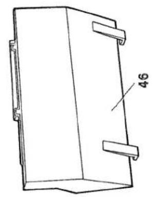
natural_image
Technical line drawing of a rectangular mechanical component with mounting brackets and a labeled dimension (no text or symbols beyond the number 46)Parts of the hobbylock 4860
| (22) | Thread guide with coloured markings |
| (23) | Telescopic thread guide |
| (24) | Spool pins |
| (25) | Thread cutter |
| (26) | Spool centering |
| (27) | Spool stands |
| (28) | Power socket |
| (29) | Main switch |
| (30) | Foot control socket |
| (31) | Hand wheel |
| (32) | Sewing foot lever |
| (33) | Stitch length adjusting knob |
| (34) | Adjusting ring for the differential feed |
| (35) | Reverse thread guide |
PFAFF
G. M. Pfaff
Aktiengesellschaft