
VRS-7100 - Audio/Video Receiver KENWOOD - Free user manual and instructions
Find the device manual for free VRS-7100 KENWOOD in PDF.
Download the instructions for your Audio/Video Receiver in PDF format for free! Find your manual VRS-7100 - KENWOOD and take your electronic device back in hand. On this page are published all the documents necessary for the use of your device. VRS-7100 by KENWOOD.
USER MANUAL VRS-7100 KENWOOD
VRS-7100 INSTRUCTION MANUAL KENWOOD CORPORATION Quick Start Reference Please read the following pages so that you can enjoy the surround sound at the best condition. {These pages give shorteut explanations on how to connect the speaker system to the receiver, set up the speakers and play a source.) “Let's play DVD video software" © About the supplied remote control Compared to standard remote controls, the remote control supplied with this receiver has several operation modes. These modes enable the remote control to control other audio/video components. In order to effectively use the remote controlit is important to read the operating instructions and obtain a proper understanding of the remote control and how to switch its operation modes (etc.| Using the remote control without completely understanding its design and how to switch the operation modes may result in incorrect operations. ODUborsv® DIGITAL:E © ( » sal WIRTUAL SPEAKER) OU dtsE B60-5462-10 02 MA (K,P,E,X) {API 0312
Before applying power À Caution : Read this page carefully to ensure safe operation. Units are designed for operation as follows. U.S.A. and Canad: Australia AC 120 V only Europe . AC 240 V only . AC 230 V only Safety precautions
CN) Sn 7 | Before applying the power How to use this manual This manual is divided into four sections, Preparations, Operations, Remote Control,and Additional Information. Preparations Shows you how to connect your audio and video components to the receiver and prepare the surround processor. Since this receiver works withall your audio and video components, we will guide you in setting up Your system to be as easy as possible: Operations Shows you how to operate the various functions available on the receiver Remote Control Shows you how to operate other components using the remote control, as well as a detailed explanation of all remote control operations. Once you have registered your components with the proper setup codes, you ‘Il be able to operate both this receiver and your other AV components {TV, VCR, DVD player, CD player, etc.Jusing the remote control supplied with this receiver Additional Information Shows you additional information such as "In case of difficulty" (trouble shooting) and "Specifications" Maintenance of the unit When the front panel or case becomes dirty, wipe with a soft, dry cloth. Do not use thinner, benzine, alcohol, etc. for these agents may cause discoloration In regard to contact cleane Do not use contact cleaners because it could cause a malfunction. Be specially careful not to use contact cleaners containing oil, for they may deform the plastic component Unpacking Unpack the unit carefully and make sure that all the accessories are present {For the U.S.A. and Canada) FM indoor antenna {1} AM loop antenna (1) {For Europe and Australia) FM indoor antenna {1} Antenna adaptor (1) Batteries (RG/AA) Qu a] Remote control unit Speaker cord connectors (4) IN ENT For Europe and Australia only I any accessories are missing, or if the unit is damaged or fails to operate, notify your dealer immediately. If the unit was shipped to you directly, notify your shipperimmediately. Kenwood recommends that you retain the original carton and packing materials in case you need to move or ship the unit in the future. Keep this manual handy for future reference.
”] | *5462/01-07/EN 4 Before applying the power GAME mode function When you connect a game machine to the GAME jacks on the front panel, the input selector of the receiver switches automatically to "GAME! and the optimum sound field for enjoying games is set. This feature improves your convenience in playing video games Special features True home theater sound —[37] - -[39 This receiver incorporates a wide variety of surround modes to bring you maximum enjoyment from your video software. Select a surround mode according to your equipment or the software you are going to play and enjoy! e Dolby Digital EX e Dolby PRO LOGIC IIx, Dolby PRO LOGIC 11 e Dolby Digital e DTS-ES e DTS NEO:6 e DTS 96/24 eDTS e DSP Mode « Dolby Virtual Speaker « Dolby Headphone pal DUAL SOURCE function [30] While you enjoy audio listening through the speakers, another person can enjoy another source (audio + video) through headphones by connecting the source to the GAME, FRONT AUX jacks. ACTIVEEQ -[31 ACTIVE EQ mode will produce a more dynamic sound quality in any condition You can enjoy a more impressive sound effect when ACTIVE EQ is turned on during Dolby Digital and DTS playback. Remote control -[ In addition to the basic receiver, the remote control supplied with this receiver can also operate almost all of your remote controllable audio and video components. Just follow the simple setup procedure to register the components you have connected RDS (Radio Data System) tuner (For Europe) [35 The receiver is equipped with an RDS tuner that provides several convenient tuning functions: RDS Auto Memory, to automatically preset up to 40 RDS stations broadcasting different programs; station name display, to show you the name of the current broadcast station; and PTY search to let you tune stations by program type. PTY (Program TYpe) search (For Europe) —[3%] Tune the stations by specifying the type of program you want to hear
- Before applying the power Contents Caution : Read the pages marked /\ carefully to ensure safe operation. À Before applying power . Ambience effects Z\ Safety precautions Surround modes How to use this manual Operations Virtual modes . Unpacking Surround play . Special features Convenient functions … Contents … Names and functions of parts. Basic remote control operations for Main unit other components . Remote control Unit Registering setup codes for other components .45 Setting up the system un Searching for your code eu. 45 Connecting à DVD player ……
- …. 9 Checking the codes p. 46
- Connecting video components, Re-assigning device keys .46 audio components 10 Operating other components …… 46 Digital connections … p. 12
- Remote Clearing all of the settings registered or Connecting the speakers Control stored in the remote control unit ….46 Connecting the speaker terminals … 15 Setup code chart (RC-RO730) (For PRE OUT connections ……. 16 U.S.A., Canada and Australia) …. 47 Connecting to the GAME jacks / Setup code chart (RC-R0730E) (For FRONT AUX jacks Europe) p. 51
- Preparations Connecting the antennas DVD player , MD recorder CD player n Preparing the remote control …… 19 & TV operations 58 @ VCR , Satellite receiver & Cable con- Let's play DVD video software verter operations 59 {For U.S.A. and Canada) Let's play DVD video software Additional! In case of difficulty. {For Europe and Australia). Information, Specifications … Preparing for playback . Speaker settings Re-assignment of rear panel jacks 28 Normal playback … … Listening to a source component … 29 Listening with headphones …… 30 Adjusting the sound 30 Recording … Analog SOUCES Digital sources Listening to radio broadcasts … Operations Tuning (non-RDS) radio stations … 33 Presetting radio stations …….… 33 Receiving preset stations Receiving preset stations in order (PCALL) … 34 Using RDS (Rai {For Europe only) … Using the RDS Disp. (Display) key. 35 Tuning by Program TYpe {PTY search} -36 Data System) ”] | *5462/01-07/EN 5 044.18, 8:00 PM p. 34
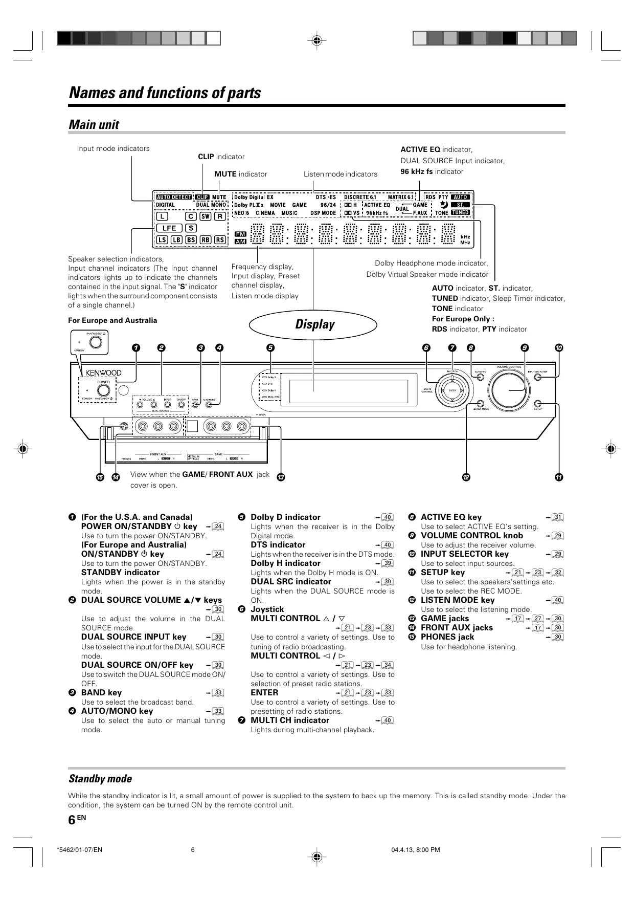
Speaker selection indicators, Input channel indicators (The Input channel indicators lights up to indicate the channels contained in the input signal. The"S' indicator lights when the surround component consists of a single channel.) For Europe and Australia Frequency display, Input display, Preset channel display, Listen mode display Display Dolby Headphone mode indicator, Dolby Virtual Speaker mode indicator AUTO indicator, ST. indicator, TUNED indicator, Sleep Timer indicator, TONE indicator For Europe Only : RDS indicator, PTY indicator cover is open. © (For the U.S.A. and Canada) POWER ON/STANDBY Ô key [2 Use to turn the power ON/STANDBY (For Europe and Australia) ON/STANDBY key -L2 Use to turn the power ON/STANDBY STANDBY indicator Lights when the power is in the standby mode © DUAL SOURCE VOLUME 4/v keys Use to adjust the volume in the DUAL SOURCE mode DUAL SOURCE INPUT key -[ä] Use to select the input forthe DUAL SOURCE mode. DUAL SOURCE ON/OFF key [2] Use to switch the DUAL SOURCE mode ON OFF © BAND key Use to select the broadcast band. © AUTO/MONO key Use to select the auto or manual tuning mode. Standby mode @ View when the GAME/ FRONT AUX jack © Dolby D Lights when the receiver is in the Dolby Digital mode. DTS indicator Lights when the receiveris inthe DTS mode. Dolby ator -G Lights when the Dolby H mode is ON. DUAL SRC indicator -60 Lights when the DUAL SOURCE mode is
© Joystick MULTI CONTROL 4 / v
Use to control a variety of settings Use to tuning of radio broadcasting. MULTI CONTROL = /©>
Use to control a variety of settings. Use to selection of preset radio stations. ENTER -20 Use to control a variety of settings. Use 10 presetting of radio stations. © MULTI CH indicator Lights during multi-channel playback.
© ACTIVE EQ key Use to select ACTIVE EQ's setting © VOLUME CONTROL knob Use to adjust the receiver volume. © INPUT SELECTOR key Use to select input sources. @ SETUP key -(9-09 -62 Use to select the speakers'settings etc. Use to select the REC MODE @ LISTEN MODE key -(0 Use to select the listening mode. @ GAME jacks @ FRONT AUX jacks © PHONES jack Use for headphone listening, While the standby indicator is lit, a small amount of power is supplied to the system to back up the memory. This is called standby mode. Under the condition, the system can be turned ON by the remote control unit 6“\ ”] | *5462/01-07/EN 6 044.18, 8:00 PM
Names and functions of parts Remote control unit This remote control unit can be use not only for Kenwood products but also for other non-Kenwood products by setting the appropriate manufacturer's setup codes. For the U.S.A, Canada and Australia: RC-R0730 For Europe : RC-R0730E À KENWOOD ) Ithe name of a fun is di rent on the receiver and on the remote control, the name of the remote control key in this manual is indicated in parentheses. © Input Selector keys (TUNER, DVD, VID 1, VID 2, AUX, F. AUX, Game) -C) Use to select input sources. Sources keys (TUNER, DVD, VID 1, VID 2, AUX, F. AUX, Game) (5) To control one of the registered sources without switching the receiver's input selector to that source, press and hold the desired input selector key for more than 3 seconds. Net Mode key, M.Card Mode key Availability may differ depending on the coun- try and sales area. © RCV (receiver) Mode key Al Use to switch the remote control to the receiver control mode. © SRC (source) Power key Use to turn the other components ON/OFF. © Numeric keys 60-69 Use to selection of preset radio stations. Use to operate other components Multi (A/V) keys -a-0a Use to control a variety of settings as well as in tuning of radio broadcasting. Use to operate other components. P.Call </:> keys Use to control a variety of settings. Use to selection of preset radio stations. Enter key -G2 Use to control a variety of settings. Use to operate other components. © +100 key Use to select MD tracks when the remote control controls the MD recorder. ”] | *5462/01-07/EN 7 TV Mute key Use to temporarily mute the TV sound © input Mode key ] Use to switch between the full auto, digitaland analog input. © Audio key Use to operate the DVD component. © Angle key Use to operate the DVD component. © Page 4/v keys Use to operate the DVD component. {For Europe only) RDS Disp. key Use to receive RDS broadcast. PTY key Use for PTY search. © CH+#/- keys Use to select the channels. D: / A4 keys If CD, MD or DVD is selected as the input source, these keys function as skip keys. ® Mute key -G Use to temporarily mute the sound. ence effects @ TV VOL+/- keys Use to adjust the TV's volume key Use to operate other components. Dimmer key Use to adjust the brightness of the displ
6 6 © © > key If CD is selected as the input source, this key functions as the play/pause key. If DVD, MD or VCR is selected as the input source, this key functions as the play key. Band key Use to select the broadcast band. Return key Use to operate the DVD component. Exit key Use to operate other components. Listen Mode A /v keys Use to select the listening mode. Info key Use to operate other components. Dolby Virtual key Use to select the Dolby Virtual mode. Active EQ key Use to select ACTIVE EQ s setting LED indicator Blinks to show that signals are being transmitted. POWER RCVR (receiver) key - Use to turn the receiver ON/STANDBY. TV Power key Use to turn the TV on and off Menu key Use to operate other components. Sleep key Use to set the Sleep timer Subtitle key Use to operate the DVD component. OSD key Use to operate the DVD component. Guide key Use to operate other components. VOL +/- keys Use to adjust the receiver volume. TV Input key Use when in TV operation: TV key Use when in TV operation: 4 >> keys I CD, MD or DVD is selected as the input source, these keys function as search key. Tune +/- keys Use to tuning of radio broadcasting ekey MD or VCR is selected, this key functions as record key, IVCR is selected, this key functions as record key when i is pressed twice sequentially Top Menu key Use to operate the DVD component. Setup key - Use to select the speakers ‘ settings etc Disc Sel. key Use to aperate ather components. Input Sel. key Use to aperate other components. Disc Skip key If CD is selected as the input source, this key functions as the muhi-CD player disc skip key. Last key Use to operate other components. mkey If CD, MD or DVD is selected as the input source, this key functions as the stop ke Auto key - Use to select the auto or manual tuning mode. Remote Setup key (2) Use ta register other components. Stereo key - Use to switch the listen mode temporary to the stereo mode
Setting up the system CAUTION Make sure that the power cord plug is disconnected from the AC wall outlet before proceeding to connections. Also be sure to disconnect the power cord plug from the AC wall outlet before changing connections: Forthe connections of other system components, see pages 9 to 18. When connecting an associated system component, be sure to read its instruction manual. Microcomputer malfunction If operation is not possible or an erroneous display appears,even though all connections have been made properly, reset the micro computer referring to ‘In case of difficulty". [86] Notes
1. Be sure to turn off the system components before connecting them.
2. Be sure to insert every connection cable completely into the jack
Incomplete connection may result in absence of audio output or production of noise:
3. Be sure to disconnect the power cord from the AC wall outlet before
inserting or removing à connection cable.
4. Installation of outdoor antenna is a dangerous work. Please have your
dealer or a specialized technician install it
5. Select the speaker installation locations with care. lf a speaker is
installed near à source of magnetism including a magnet, the mutual interference with the speaker may produce color irregularities on the TV screen Analog audio connections Audio connections are made using RCA pin cords. These cables transfer stereo audio signal in an “analog" form. This means the audio signal corresponds to the actual audio of two channels. These cables usually have 2 plugs on each end,one red for the right channel and one white for the left channel These cables are to be prepared separately by the user. CAUTION Be sure to adhere to the following, or proper ventilation will be blocked causing damage or fire hazard. Do not place any objects impairing heat radiation onto the top of the unit. e Leave some space around the unit (from the largest outside dimension including projection) equal to or greater than, shown below. Top panel : 50 em Side panel Ocm Back panel gen ”] | *5462/08-19/EN 8 Input mode settings DVD, VIDEO 1, VIDEO 2, AUX and GAME inputs each include jacks for digital audio input and analog audio input The initial factory settings for audio signal playback for DVD, VIDEO 1, VIDEO 2, AUX and GAME are full auto. After completing connections and turning on the receiver follow the steps below INPUT SELECTOR LT 68;0!] certes j|
Input Selector keys Input Mode © Use the INPUT SELECTOR key (or Input Selector keys) to select DVD, VIDEO 1, VIDEO 2, AUX or GAME. © Press the Input Mode key. Each press switches the setti @ ‘F-AUTO": Auto detect (AUTO DETECT" indicator lights up) @ ‘D-MANUAL': Fixed to digital input (DIGITAL: indicator lights up) *ANALOG": Fixed to analog input # (AUTO DETECT, ‘DIGITAL! indicator goes off) Can not be selected for DTS playback. g as follows:
Auto detect: InF-AUTO (FULL AUTO)" mode (AUTO DETECT'indicator light up}, the receiver detects the digital or analog input signals automatically. The receiver will select the input mode and listen- ing mode automatically during playback to match the type of input signal (Dolby Digital, PCM, DTS) and the speaker setting. [26 The "DIGITAL" indicator lights up when à digital signal is detected. The "DIGITAL" indicator is extinguished when no digital signal is detected Fixed to digital input: Select this mode if you want to keep the decoding condition {Dolby Digital, DTS, PCM, etc.} in the current listen mode. When ‘D-MANUAL (DIGITAL MANUALI" mode is selected, the setlisten modes may be changed automatically depending on the listen mode Fixed to analog input: Select this setting to play analog signals from a VCR, etc. If the Input Mode key is pressed quickly, sound may not be produced. Press the Input Mode key again 044.13, 8:00 PM
”] | *5462/08-19/EN 9 Setting up the system Connecting a DVD player Hyauhave connected a DVD playertothe receiverwith digital connection be sure to read the "Input mode settings’, ‘Re-assignment of rear panel jacks' section carefully. For U.S.A. and Canada Monitor TV COMPOSITE VIDEO IN (Yellow RCA pin cords) « Digital audio connections are required when playing multi-chan- nel signals such as the Dolby Digital and DTS signals. « To play the DVD player connected in this page, select the "DVD" input selector. [22] For Europe and Australia Monitor TV COMPOSITE VIDEO IN [ (Yellow RCA pin cords)
DIGITAL OUT (AUDIO) DVD player {Coaxial cord)
$ VIDEO OUT {S VIDEO cord) $ AUDIO LINE OUT or RE MIX LINE OUT (Yellow RCA {Audio cord} pin cords) DIGITAL OUT (AUDIO) {Coaxial cord) DVD player gen 044.18, 8:00 PM
Setting up the system Connecting video components, audio components For U.S.A. and Canada Audio components Sem ‘0e AUDIO LINE OUT {Audio cord) Monitor TV
ŒE > Connecting video components (COMPONENT VIDEO) If you have connected the receiver to a video component with COMPONENT jacks, you can get a better picture quality than by connecting to the S VIDEO jacks. When connecting a video component with COMPONENT jacks, see ‘Re-assignment of rear panel jacks_ — When connecting the TV to the COMPONENT jacks, be sureto connect all the other components to the COMPONENT jacks. CERN Monitor TV {with component jacks) courge =
[FT see see + À HDD Recorder, DVD Recorder, r] Satellite Cable Tuner & Game Cr OUT Player (with component jacks) de 0e OUT — 1 | vour —|
DVD player (with component jacks) CE TE
YOUT 044.18, 8:00 PM
Setting up the system For Europe and Australia Audio components D Se ‘oi AUDIO LINE OUT {Audio co Monitor TV VIDEO IN (Yellow RCA pin cords)
Video deck, Cassette deck or MD recorder
(Yellow RCA pin cords) LINE OUT {Audio cord) Connecting video components (S VIDEO) Use the S VIDEO jacks to make connections to video compo- nents with S VIDEO IN/OUT jacks. e !f you use the S VIDEO jacks to connect your video playback components, be sure to use the $ VIDEO jacks when con- necting your monitor and video recording components. SvoEo
Setting up the system Digital connections The digital in jacks can accept DTS,Dolby Digital,or PCM signals.Connect components capable of outputting DTS,Dolby Digital or PCM (CD) digital signals. If you have connected a DVD player to the receiver with digital connection,be sure to read the ‘Input mode settings’, "Re-assignment of rear panel jacks' section carefully.… DTS disclaimer clause DTS Digital Surround" playback, this ui When playing DTS-encoded discs, excessive noise will be exhibited from the analog stereo outputs of the CD or DVD player. To enjoy must be connected to the digital output of the CD or DVD player. For U.S.A. and Canada For Europe and Australia free
OPTICAL DIGITAL OUT (AUDIO) (Optical fiber cord) Connect the analog audio signals 10 the AUX jacks (See “Connecting video compo- nents,audiocomponents”. —[i COAXIAL DIGITAL OUT (AUDIO) Satellite Cable Tuner {Coaxial cord) Connect the video signal and ana- log audio signals to the VIDEO 2 jacks. (See “Connecting video compo- nents,audiocomponents”. —[i 12" 5462/08-19/EN 12 DGA or1 opr2 QDEO 1) (AUX) CD player or DVD player a L TES
OPTICAL DIGITAL OUT (AUDIO) (Optical fiber cord) Connect the analog audio signals 10 the AUX jacks (See “Connecting video compo- nents,audiocomponents”. -[i1)) COAXIAL DIGITAL OUT (AUDIO) Satellite Cable Tuner (Coaxial cord) Sep © OO Connect the video signal and ana- log audio signals to the VIDEO 2 jacks. (See ‘Connecting video compo- nents,audiocomponents”. -[ii)) 044.18, 8:01 PM
CN) Sn 7 | Setting up the system Connecting the speakers For U.S.A. and Canada CAUTION Make sure that the power cord plug is disconnected from the AC wall outlet before proceeding to speaker cord connections. H the conductor wires on the extremity of speaker cord are untwisted, there is a risk of short- them well before connecting the speaker cord. cuiting. Be sure to twist Front Speakers Right Left Center Speaker Righ Ÿ ® Surround Speakers Be sure to connect both Whether each speaker is connected properly can be confirmed by outputting the test tone and checking if each speaker channel outputs audio. For details, see “Speaker settings" (Step M Adjust the speaker volume level. — Protection circuitry This unit incorporates protection circuitry, which may be activated during high-power reproduction or in case of extreme rise in tempera- ture When the protection circuitry is activated, the output from this unit is Shut down and the STANDBY indicator blinks In this case, turn this unit OFF then ON again and reduce the output volume level surround speakers t Left
(RIsurR (L) Subwoofer/ Surround Back Speaker Whenthe surround back speakeris connected to these terminals, set the speaker setting to "BS/SW BS' Inthis case, the subwoofer should be connected to the PRE OUT SUBWOOFER jack
Setting up the system For Europe and Australia Whether each speaker is connected properly can be CAUTION .. confirmed by outputting the test tone and checking if Make sure that the power cord plug is disconnected from the AC each speaker channel outputs audio. For details, see wall outlet before proceeding to speaker cord connections. M re 4 I the conductor wires on the extremity of speaker cord are Speaker settings" (Step F Adjust the speaker volume untwisted, there is a risk of short-circuiting. Be sure to twist level]. - them well before connecting the speaker cord. Protection circuitry This unit incorporates protection circuitry, which may be activated during high-power reproduction or in case of extreme rise in tempera- ture When the protection circuitry is activated, the output from this unit is Shut down and the STANDBY indicator blinks In this case, turn this unit OFF then ON again and reduce the output volume level Front Speakers Surround Speakers Be sure to connect both surround speakers Subwoofer/ Surround Back Speaker Right | | tft When the surround back speaker is connected to these terminals, set the speaker setting to"BS/SW BS- rm = In this case, the subwoofer should be connected to the Right Lot PRE OUT SUBWOOFER jack — © Center Speaker
Setting up the system Connecting the speaker terminals For U.S.A. and Canada © Strip coating. © Insert the cord.
Twist © Push the lever. © Return the lever. For Europe and Australia © Strip coating. © Insert. : 4 Twist © Loosen. © Secure. Ithe provided speaker cords are too short, they can be replaced with commercially available speaker cords [AWG24-18 standard {conductor section diameter 0.511 to 1.024 mm(0.02 to 0.04 in.))]. When using commercially available speaker cords, strip the vinyl coating on the end of each cord by about 1 em (0.39 in.) andtwist the conductor wires so that they are not disentangled. Attaching the speaker cord connectors; Connecteach speaker cord by matchingthe color ofthe connector with that of the terminal to which the speaker cord is to be connected. Connected Connected speaker Connector | Connecté Center speaker Green CENTER Surround speaker (Right) Grey SURR R Surround speaker (Left) Blue SURR L Surround back speaker Brown SURR BACK/SW or Subwoofer While applyingthe projected part ofthe connector against a hard desktop, ete., insert the conductor sections of the speaker cord into the connector. Projected part {Wiite) Afterattachingthe speaker cordconnector, holditandpullthe speaker cord lightly to ensure that it will not come out Connect the connector to the terminal on the receiver same color by inserting the connector straight until it clicks. Green Grey von BE, SU à Blue K Confirm the connector orientation before insertion. © Never short circuit the + and speaker cords @ lf the left and right speakers are connected inversely or the speaker cords are connected with reversed polarity, the sound will be unnatural with ambiguous acoustic imaging. Be sure to connect the speakers correctly. Speaker impedance After confirming the speaker impedance indications printed on the rear panel of the receiver, connect speakers with matching imped- ance ratings. Using speakers with a rated impedance other than that indicated on the rear panel of the receiver could result in malfunctions or damage to the speakers or receiver Speaker placement Center speaker Subwoofer Listening Y PA ee D æ æ
“Surround Back Right speaker “Surround Back | |/ Loft speaker “Surround Back speaker
- For Surround Back speaker, you may place either two Surround Back speakers (Surround Back Left speaker and Surround Back Right speaker) for 7.1 channel surround sound system or one Surround Back speaker for 6.1 channel surround sound system: Front speakers : Place the leftand right speakers at each side of your TV. Angle the speakers towards the listening area to enhance the stereo effect Center speaker : Place the center speaker on the center between the front left and right speakers. Tilt the speaker upward or down-ward so that it is directly facing the listening area. Surround speakers : Place the surround speakers as high as possible, either directly to the sides of the listening area or else slightly behind the listening area. Adjust the angles so that these speakers are facing directly towards the listeners. Subwoofer : Usually, place the subwoofer inthe front center position in the listening room, near one of the front speakers near the center speaker. (Since the subwoofer has less directivity than other Speakers, it can be placed almost in any position that can offer the best low frequency reproduction according to the room layout.) Surround back speakers : Place the surround back speaker behind the listining position, at the same height as the left and right surround speakers. Although the ideal surround system consists of all the speakers listed above, if you don't have a center speaker or a subwoofer, you can divide those signals between the available speakers in the speaker settings steps to obtain the best possible surround reproduction from the speakers you have available. [22] ”] | *5462/08-19/EN 15
Setting up the system PRE OUT connections The receiver has additional PRE OUT jacks. Note that the output from the PRE OUT jacks needs to be connected to an external power amplifier. you want to connect surround back speakers to these jacks, be always sure to connect two surround back speakers for the left and right For U.S.A. and Canada « Connecting a speaker cord directly to a PRE OUT jack will not produce any sound from the speaker. For Europe and Australia ICESS TT 509 Ppoce = F [ ( SÆ|Smx loo0 2Soat JE mm (dope sursouno sac PREOUT & “ Example: & à Fe When you want to connect two surround back À speakers. e When the subwoofer is connected to the SURR BACK/SW terminals. Surround Back speakers
Example: © When the surround back speaker is connected to the SURR BACK/SW terminals. Subwoofer Power amplifier Q n——
[moorer|surrounD aacx PRE OUT ê Example: © When you want to connect two surround back speakers. e When the subwoofer is connected to the SURR BACK/SW terminals Surround Back speakers
Power amplifier Example: © When the surround back speaker is connected to the SURR BACK/SW terminals. Subwoofer Power amplifier Powered subwoofer ES, Powered subwoofer
”] | *5462/08-19/EN 17 Setting up the system Connecting to the GAME jacks / FRONT AUX jacks H you use a component that you do not usually connect ta the receiver, such as a portable video camera, connect it to the GAME or FRONT AUX jacks on the front panel of the receiver. These jacks are particularly convenient when dubbing audio/video from a portable video camera INPUT SELECTOR -00 ( hesocees)] mm) Fr eRs OPTICAL DIGITAL
AUDIO VIDEO OUT OUT LI L+ Camcorder Game Player ‘ The DIGITAL IN (OPTICALI jack in the GAME jack section can be used for connection of digital audio input. TI playing a video game through the receiver. convenient for
Setting up the system Connecting the antennas AM loop antenna The supplied loop antenna is for use indoors. Place it as far as possible from the receiver, TV set, speaker cords and power cord, and adjust the direction for best reception FM indoor antenna The supplied indoor antenna is for temporary use only. For stable signal reception we recommend using an outdoor antenna. Disconnect the indoor antenna when you connect one outdoors. AM antenna terminal connections © Push lever. @ Insert cord. © Release lever. FM antenna terminal connections Insert the connector. {For the U.S.A. and Canada) {For Europe and Australia) FM outdoor antenna Lead the 75Q coaxial cable connected to the FM outdoor antennaintothe room and connect it to the FM 750 terminal For the U.S.A. and Canada FM indoor antenna Antenna adaptor
”] | *5462/08-19/EN 19 Setting up the system Preparing the remote control Loading the batteries © Remove the cover. @ Insert the batteries. © Insert two AA-size (RG) batteries as indicated by the polar- ity markings Remote control operation When the STANDBY indicator is lit, the power turns ON when you press the POWER RCVR on the remote control. When the power comes ON, press the key you want to operate. Operating other Remote sensor component range © When pressing more than one remote control key successively, press the keys securely by leaving an interval of 1 second or more between keys. Notes The supplied batteries may have shorter lives than ordinary batteries due to use during operation checks: When the remote-controllable distance gets shorter than before, replace both batteries with new ones. Placing the remote sensor in direct sunlight, or in direct light from a high frequency fluorescent lamp may cause a malfunction: In such a case, change the location of the system installation to prevent malfunction. 044.18, 8:01 PM 19"
”] | *5462/20-36/EN 20 Let play DVD video software (For U.S.A. and Canada) S TEP 1 connectthe speakers and TV to the receiver. For details, see “Setting up the system CAUTION Make sure that the power cord plug is disconnected from the AC wall outlet before proceeding to speaker cord connections. Ifthe conductor wires on the extremity of speaker cord are untwisted, there is a risk of short-circuiting. Be sure to twist them well before connecting the speaker cord. Connection of speakers: c D _ ] Front speakers (LA) [ 8 [ ®_ | Center speaker & 4 ® RECEIVER À oo © | Surround speakers (LR) Surround back speaker © lf you want to connect two surround back speakers (LB and RB) to the PRE OUT SURROUND BACK jacks, see ‘PRE OUT L: RS connections". -[1f] y Listening position À Ni ff a e
Connection of TV monitor: Connection of DVD player: (2 Component video connection — Component video connection @- - | Composite video connection — Composite video connectiona e For the video input connection from the DVD player and the video G Pi Prev @_ | Digital audio connection (Coaxial cord) output connection ta the TV monitor, use either the component video or composite video connection for both of them: Œ Analog audio connection 20° 044.18, 8:01 PM | F
”] | *5462/20-36/EN 21 Let's play DVD video software (For U.S.A. and Canada) S TEP 2 set up the speakers. For details, see ‘Speaker settings"
POWER ON/STANDBY INPUT SELECTOR
© D [re El Connect the power cord to the AC wall outlet and press (_) . . x poesss ess] Î = La
Hyour selection is correct, press ©) select'OK'andpress © When the speaker setting is set to "HTB1 5.1CH', ‘HTB2 5.1CH' or ‘HTB3 5.1CH', the PL 1x, DTS-ES and DOLBY EX listen modes cannot be selected. H you use another speaker system want a setup according to it: to select "CUSTOM" and press @) to select each of the speaker setup items:
Press > to select the speaker setup item Press
to select the setting for each item
SUBW SUBW ON: A subwoofer is connected. SUBW OFF: No speaker is connected. ERNT Speaker size ? LRG: Relatively large-size speakers. NML: Normal-size speakers. CNTR, SURR, BS Speaker size ? LRG: Relatively large-size speakers. NML: Normal-size speakers. OFF: No speaker is connected BS/SW BS/SW BS: À surround back speaker is connected to the SURR BACK/SW terminals. BS/SW SW: À subwoofer is connected to the SURR BACK/SW terminals BS/SW OFF: No speaker is connected. I your selection is correct, press @) Now the speaker setup is complete. (Select "CANCEL" to return to the status before setup.) After completing the setup, press select "OK" and press «When the speaker setting is set to"BS/SW OFF", the PL IIx, DTS-ES and DOLBY EX listen modes cannot be selected. e More detailed settings such as the volume level of each speaker and distance to each speaker are also available. — STEP 3 Play a disc on the DVD player. Press © toselect"DVD". B start playback ofthe DVD player. For the operation, also refer to the instruction manual for your DVD player. e You can select various listen modes to enjoy surround playback of various kinds of video software. -[&f] 21" 044.18, 8:01 PM | F
Let play DVD video software (For Europe and Australia) S TEP 1 connectthe speakers and TV to the receiver. For details, see “Setting up the system CAUTION Make sure that the power cord plug is disconnected from the AC wall outlet before proceeding to speaker cord connections. Ifthe conductor wires on the extremity of speaker cord are untwisted, there is a risk of short-circuiting. Be sure to twist them well before connecting the speaker cord. Connection of speakers: c | Front speakers (LR) [ [ ®_ | Center speaker 4 4: ® £ © | Subwoofer L 1] vw R © | Surround speakers (LR) Surround back speaker D + DvD © lf you want to connect two surround back speakers (LB and RB) to the PRE OUT SURROUND BACK jacks, see ‘PRE OUT nes LE L: ; — pe RS connections’ [16] Listening position à L Ss ® \(E ÿ_ NI p) + ro: ©
Connection of TV monitor: Connection of DVD player: @:.[ S VIDEO connection — S VIDEO connection @- - | Composite video connection — Composite video connection e For the video input connection from the DVD player and the video GT Digial audio connocton (Coaxal cod output connection to the TV monitor, use either the S VIDEO or = Age? audio connection 1Coaxiar cor @ [Analog audio connection composite video connection for bath of them. 22" ”] | *5462/20-36/EN 2 044.13, 8:01 PM | [
”] | *5462/20-36/EN 23 Let's play DVD video software (For Europe and Australia) S TEP 2 set up the speakers.
ON/STANDBY © INPUT SELECTOR
For details, see ‘Speaker settings"
Hyour selection is correct, press ©) select'OK'andpress © When the speaker setting is set to "HTB1 5.1CH', ‘HTB2 5.1CH' or ‘HTB3 5.1CH', the PL 1x, DTS-ES and DOLBY EX listen modes cannot be selected. H you use another speaker system want a setup according to it: to select "CUSTOM" and press @) to select each of the speaker setup items:
Press > to select the speaker setup item Press
to select the setting for each item
SUBW SUBW ON: A subwoofer is connected. SUBW OFF: No speaker is connected. ERNT Speaker size ? LRG: Relatively large-size speakers. NML: Normal-size speakers. CNTR, SURR, BS Speaker size ? LRG: Relatively large-size speakers. NML: Normal-size speakers. OFF: No speaker is connected BS/SW BS/SW BS: À surround back speaker is connected to the SURR BACK/SW terminals. BS/SW SW: À subwoofer is connected to the SURR BACK/SW terminals BS/SW OFF: No speaker is connected. I your selection is correct, press @) Now the speaker setup is complete. (Select "CANCEL" to return to the status before setup.) After completing the setup, press select "OK" and press «When the speaker setting is set to"BS/SW OFF", the PL IIx, DTS-ES and DOLBY EX listen modes cannot be selected. e More detailed settings such as the volume level of each speaker and distance to each speaker are also available. — STEP 3 Play a disc on the DVD player. Press © toselect"DVD". B start playback ofthe DVD player. For the operation, also refer to the instruction manual for your DVD player. e You can select various listen modes to enjoy surround playback of various kinds of video software. -[&f] 23" 044.18, 8:01 PM | F
Preparing for playback Speaker settings To enable you to obtain optimum enjoyment from the receiver’s listening modes, make sure to complete the speaker settings (subwoofer, front, center, surround and surround back speakers) as described below.
HE man arr (5 ] Enter Turn on the power to this receiver by pressing the POWER ON/ STANDBY (For U.S.A. and Canada) or ON/STANDBY © (For Europe and Australia) key (or POWER RCVR key). B r you want to use the remote control unit, press the RCV Mode Key on the remote to set it to the receiver control mode. Initiate the setup mode. © Press the SETUP key (or the Setup key). @ Usethe MULTICONTROL </t> (orthe Multi <1/1> keys) for the following displays. 5 “LFE LEVEL GAME FUNC' D'EXIT e While the main setup screen is displayed, the setup mode can be canceled by pressing the SETUP key (or the Setup key) or selecting"EXIT: and then pressing the ENTER (or the Enter key). E setect the setup method. © Select "SP SETUP" and press the ENTER key (or the Enter key) to select the speaker setup method. 24“ ”] | *5462/20-36/EN 24 © Usethe MULTICONTROL </t> (orthe Multi </c> keys) for the following displays. D “HTB1 6.1CH': Select "HTB1 6.1CH' if you use speaker system KS-3100EX. * TB1 5.1CH': Select "HTB1 5.1CH' if you use speaker system KS-2100HT. * TB2 6.1CH: Select ‘HTB2 6.1CH" if you use speaker system KS-708HT+KS-308EX or KS-308HT+KS-308EX. * “HTB2 5.1CH': Select "HTB2 5.1CH' if you use speaker system KS-708HT or KS-308HT. * "HTB3 6.1CH': Select "HTB3 6.1CH' if you use speaker system KS-908EX. * "HTB3 5.1CH: Select "HTB3 5.1CH° if you use speaker system KS-908HT.* “CUSTOM': Select to set up the speakers according to the speaker system in use. (Speaker setup is required every time after the speaker system is changed.) XIT': Press the ENTER (or the Enter key) again to return to the main setup displays *_ Model availability may differ depending on the country and sales area e_ When the 5.1 channel speaker system configuration is used orthe speaker settingis set to'BS/SW OFF", the PL IIx, DTS- ES and DOLBY EX listen modes cannot be selected If you selected "HTB1 6.1CH", "HTB15.1CH", "HTB2 6.1CH", “HTB25.1CH", "HTB3 6.1CH" or “HTB3 5.1CH" in the above: Press ENTER (or the Enter key), then press MULTI CONTROL A1 Vorthe Multi A / v keys] to select'OK", and press ENTER {or the Enter key) again to establish the setup. « Select CANCEL" to return to the status before setup e When you use a KENWOOD speaker system and select “HTB1 6.1CH', ‘HTB1 5.1CH, "HTB2 6.1CH', HTB2 5.1CH', “HTB3 6.1CH' or "HTB3 5.1CH' set the speaker setup, the audio will be corrected automatically according to the speaker characteristics. If you selected “CUSTOM' Press ENTER (or the Enter key) to proceed to detailed setups: the above: The flow of the SETUP is as follows; e_ The subwoofer setting indication *SUBW! appears NUZ © Es - _ GIN Ci Ti Fin @ © @ Li À V4 LI DU Continued to next page 044.18, 8:01 PM
Preparing for playback D 5 © BEBE E serect a speaker system. © Usethe MULTICONTROL A / v (orthe Multi A / V keys) to select the appropriate subwoofer setting. SUBW ON [ When a subwoofer is connected. @ "SUBW OFF When no subwoofer is connected © The initial setting is *SUBW ON" e_When"SUBW OFF" is selected and the selection is established by pressing MULTI CONTROL (or the Multit- key) in step @ below, the front speakers are set automatically to FRNT LRG* and the procedure jumps to step @ © Use the MULTI CONTROL £- (or the Multi &> key) to accept the setting. «The front speakers setting indication "FRNT" appears AL AL he CDLS
HS ASC IDCIAT PO ODT
m ® ® MIT I LP © Usethe MULTICONTROL A / (orthe Multi A / keys) to select the appropriate front speakers setting. @ ‘FRNT LRG [ Large front speakers are connected to the receiver. @ *FRNT NML' Average size front speakers are connected to the receiver + When the subwoofer setting is 'SUBW ON’, front speak- ers setting is ‘FRNT LRG' and a stereo source is played, the low frequencies may be reproduced through the front speakers and no audio output fro the subwoofer in certain listen modes. In this case, set the subwoofer re- mix setting in step ® to "REMIX ON" to output the low frequencies from the subwoofer © Use the MULTI CONTROL > (or the Multi &> key) to accept the setting. «The center speaker setting indication "CNTR' appears © Usethe MULTICONTROL 2 / V (orthe Multi A / V keys) +0 select the appropriate center speaker setting. H you selected “FRNT LRG" as the front speakers set
A large center speaker is connected to the receiver. @ "ENTR NML' An average size center speaker is connected to the receiver @ "CNTR OFF' When no center speaker is connected H you selected “FRNT NML" as the front speakers setti @ "ENTR NML' Average size front speakers are connected to the receiver @ "CNTR OFF When no center speaker is connected © Use the MULTI CONTROL t> (or the Multi &> key) to accept the setting. «The surround speaker setting indication “SURR' appears ”] | *5462/20-36/EN 25 © Usethe MULTICONTROL 2 / V (orthe Multi A / V keys) to select the appropriate surround speaker setting. @ ‘SURR LRG' Large surround speakers are connected to the receiver. URR NML' Average size surround speakers are connected to the receiver URR OFF When no surround speakers are connected When ‘SURR OFF" is selected and the selection is estab- lished by pressing MULTI CONTROL :> in step © below, the procedure jumps to step ®. However, if the subwoofer setting is ‘SUBW OFF’, the procedure jumps to step @ so that you can complete the speaker setup and proceed to the speaker volume level adjustment in step Bi. © Usethe MULTI CONTROL t- (or Multi > key) to ac- cept the setting. e_ The surround back speaker setting indication "BS' appears © Usethe MULTICONTROL A / v (or the Multi A / V keys) to select appropriate surround back speaker setting. H you selected “SURR LRG" as the surround speaker settini @ *BS LRG' Large surround back speaker is connected to the re- ceiver @ *BS NML' Average size surround back speaker is connected to the receiver @ *BS OFF' When no surround back speakers is connected
DE Dr æ L. PL S NML' Average size surround back speaker is connected to the receiver S OFF' When no surround back speakers is connected © Use the MULTI CONTROL £- (or the Multi > key) to accept the setting. «The surround back speaker and subwoofer setting mode indication "BS/SW" appears Continued to next page
Preparing for playback @ Usethe MULTICONTROL A / v (orthe Multi A / keys) to select the appropriate BS/SW amp setting. @ ‘BS/SWBS" Select this setting when a surround back speaker is connected to the SURR BACK/SW terminals. In this case, the subwoofer signal will be output from the PRE OUT SUBWOOFER jack. ‘BS/SW SW Select when the subwoofer speaker is connected to the SURR BACK/SW terminals. In this case, the surround back signals will be output from the PRE OUT SUR- ROUND BACK jacks
Select when no speaker is connected to the SURR BACK/SW terminals. In this case, the subwoofer signal will be output from the PRE OUT SUBWOOFER jack and the surround back signals will be output from the PRE OUT SURROUND BACK jacks + 1f‘BS/SW BS' is selected, only one surround back speaker can be connected to the receiver e_1f"BS/SW SW or 'BS/SW OFF' is selected, two sur- round back speakers can be connected to the PRE OUT SURROUND BACK jacks through an external power amplifier. [9 @ Use the MULTI CONTROL > (or the Multi &> key) to accept the setting. e_ The subwoofer re-mix setting indication *REMIX appears. @ Usethe MULTICONTROL A / V (orthe Multi A / V keys) to select the appropriate subwoofer re-mix setting. IF*REMIX ON" is selected as the subwoofer re-mix setting, the low frequencies are enhanced by adding the low fre- quencies of other channels to the subwoofer channel or adding the low frequencies of the subwoofer to other channels depending on the speaker setup REMIX ON‘ Subwoofer re-mix setting mode to the receiver is ON "REMIX OFF" Subwoofer re-mix setting mode ta the receiver is OFF. The initial setting is *REMIX ON" «The subwoofer re-mix setting is possible only when the subwoofer setting is "SUBW ON" and the front speaker setting is ‘FRNT LRG' © Press ENTER (or the Enter key). If your selection is correct, press MULTI CONTROL 2 / Y (or the Multi A | V key) to select "OK". Press the ENTER (or the Enter key) again to return to the main setup displays. e Select CANCEL' and press the ENTER (or the Enter key) to return to the status before setup e_In steps @ and H indications appear only for the se- lected channels of the speakers that require adjusting
”] | *5462/20-36/EN 26 G Ajust the speaker volume level. From your usual listening position, adjust the volume levels. The volume levels from each speaker should be the same © Use the MULTICONTROL </1> (orthe Multi </t> keys) to select "SP LEVEL" on setup displays, and press the ENTER (orthe Enter key). © Usethe MULTICONTROL </1- (orthe Multi </1> keys) to select "AUTO", “MANUAL" or "OFF". D “AUTO”: Select this setting to adjust the speaker volume levels using the test tone. The test tone wil be output from every speaker channel in automatic sequence @ ‘MANUAL": Select to select the speaker channel to output the test tone using MULTI CONTROL / &- {or the Multi < / & key) "OFF': Select to adjust the speaker volume levels using the current output signals. The speaker chan- nel to output the output signal can be selected using MULTI CONTROL=</1> (or the Multi </1> key) ‘EXIT': Press the ENTER (or the Enter key) again to return to the main setup displays When"AUTO"or"MANUAL"is selected andENTER (orthe Enter key) is pressed again, the test tone output will start. Usethe MULTICONTROL 2 / V (orthe Multi A / Y keys) to adjustthe volume level ofthetesttone outputfrom the speaker channel to be adjusted. For "AUTO" selection, the first test tone is heard from thefront left speaker for 2 seconds. The nexttesttone is heard from the speakers in the following sequence for 2 seconds each. When the "BS/SW BS" has been selected : L c R RS sw LS Bs ] When the "BS/SW SW" or “BS/SW OFF" has been selected: L c R RS sw LS LB RB | The channel indication blinks while the test tone is being output
£oæ® © © © L 7 Î al ci È e_lfyou change the volume level settings for the speakers while listening to musie, the settings referred to on this page are also changed e_ If the speaker set settings are reset When “MANUAL" or “OFF is selected, press MULTI CONTROL </1- (or the Multi </t- key) to select the speaker channel and then press MULTI CONTROL A/V {orthe Multi A/V key)toadjustthespeakervolumelevel. g selects are OFF, the speaker level © Press the ENTER (or the Enter key) again to return to the main setup displays. e The test tone is turned off and return to the main setup displays. 044.18, 8:01 PM
Preparing for playback Input the distance to the speakers. This setting allows the signals output from different speakers to reach the listening position simultaneously. Measure the distance from the listening position to each of the speakers. Jot down the distance to each of the speakers. Distance to Front speaker (Li ___ feet (meters) Distance to Center speaker (C) ___ feet (meters) Distance to Front speaker (R) ___ feet (meters) Distance to Surround speaker (RS) ___ feet (meters) Distance to Surround back speaker (RB)_: ____ feet (meters| Distance to Surround back speaker (LB): ___ feet (meters Distance to Surround speaker (LS| ___ feet (meters) Distance to Subwoofer (SW) ___ feet (meters) © Usethe MULTICONTROL </1> (orthe Multi </t> keys) to select "DISTANCE" on setup displays, and pressthe ENTER (orthe Enter key). © Use the MULTI CONTROL </ 1 (or the Multi < / &> key) to select the unit and press ENTER (or the Enter key). METERS" FEET: EXIT': Press the ENTER (or the Enter key) again to return to the main setup displays © Usethe MULTICONTROL </t- (orthe Multi /1> keys) to select the speakers and the MULTI CONTROL À / v {or the Multi A / V keys) to adjust the distance to the front speakers. The speaker indicator to be adjusted blinks «The speakers you have selected should appear onthe display. Contirm that all the speakers have been correctiy selected ! 71 CA M4 L.. RAR Indication in meters e_ The allowable setting range is 1 to 30 feet (0.3 to 9.0 mi, adjustable in 1 foot (0.3 m) increments © Repeat steps © to input the distance for each of the speakers. © Press the ENTER (or the Enter key) again to return to the main setup displays. ”] | *5462/20-36/EN 27 E Adjust the LFE LEVEL (Low Frequency Effects level) Adjust the level of the low-frequency fields effect (LFE) signal, which is the signal used exclusively for giving the field effect of bass tone, in the Dolby Digital or DTS signal. © Use the MULTI CONTROL < / & (or Multi <1 / &> keys) to select "LFE LEVEL" on setup displays, and pressthe ENTER (or the Enter key). © Use the MULTI CONTROL À / (or Multi A / V keys) to adjust the LFE LEVEL.
PO T VA .J T LUC ui ci à e The LFE LEVEL is adjusted from OdB to -10dB in 1dB step decrements © Press the ENTER (or the Enter key) again to return to the main setup displays. E set up the GAME jacks on the front panel. Perform the setup for convenience of playing a video game using the receiver © Use the MULTI CONTROL < / &- (or Multi <1 / c> keys) to select "GAME FUNC" on setup displays, and press the ENTER (or the Enter key). © Press MULTICONTROL À / (orthe Multi A / key) to select the game mode. When the connected game machine is turned ON, the input selector is switched automatically to "GAME". In addition, the ACTIVE EQ function is switched to"EQ GAME" and the listen mode is switched ta the appropriate mode for games. @ ‘MODE 2: When the connected game machine is turned ON, the input selector is switched automatically 10 GAME” @ "OFF The game mode is switched OFF. «The game mode is not activated if no video signal is input to the VIDEO jack in the GAME jack section e The game mode is not activated when the DUAL SOURCE function is switched ON © Press the ENTER (or the Enter key) again to return to the main setup displays. 27" 044.18, 8:01 PM
Preparing for playback Input level adjustment (analog sources only) Ithe input level of an analog source signal is too high, the "CLIP" indicator will lights up to indicate the source signal. Adjust the input level. © Pressthe RCV Mode key on the remote control unit to set it to the receiver control mode. © Press the Sound key. © Usethe MULTICONTROL </L> (or the Multi </ L> keys) to select "INPUT", and press the ENTER (or the Enter key). © Use the MULTI CONTROL A / Ÿ (or the Multi A / V keys) to adjust the input level. [a] TRAIT LES LIN LI ki 1 e The adjustment mode is displayed for approximately 20 seconds e The input level may be adjusted to any one of three settings OdB, -3dB, and -6dB. (The initial setting is OdB.} e You can store a separate input level for each input selector. © PresstheSoundkey againtoreturntotheinputindication. Re-assignment of rear panel jacks The assignment of the input selector positions to the digital audio and component video input jacks can be changed as desired © Press the SETUP key (or the Setup key). @ Use the MULTI CONTROL </1> (or the Multi < /1> keys) to select "ASSIGN." on setup displays, and press the ENTER (or the Enter key). © Use the MULTI CONTROL < / &> (or Multi < / &> keys) to select "DIGITAL" or "COMPONENT VIDE. the ENTER (or the Enter key). D "DIGITAL": Select to change the assignment of the digital audio input jacks of the receiver. 2 *COMPONENT VIDEO'*: Select to change the assignment of the component video input jacks of the receiver. 3 “EXIT*: Press the ENTER (or the Enter key) again to return to the main setup displays.
- For U.S.A. and Canada only. and press
IN2 (VIDEO 2) Assigned input selector e_Itis not permitted to assign two input selector positions for one input jack. In this case, you will have to assign different input selector positions again © Repeat step @ until you have assigned the desired jacks to the desired input selector posi © Press the ENTER (or the Enter key) again to return to the main setup displays. 044.18, 8:01 PM
Normal playback Some preparatory steps are needed before starting playback.
Input selector keys 29,0 RCV Mode POWER RCVR Input Mode Turning on the receiver © Turn on the power to the related components. © Turn on the power to this receiver by pressing the POWER ON/STANDBY 6 or ON/STANDBY © key (or the POWER RCVR key). Selecting the input mode If you have selected a component connected to the COAX 1 (DVD), COAX 2 (VIDEO 1), OPT 1 (VIDEO 2), OPT 2 (AUX) or DIGITAL IN (OPTICAL) jacks, make sure thatthe input mode settingis correct for the type of audio signal to be used. ë
VOLUME CONTROL Press the INPUT SELECTOR key (or the Input selector keys/ DVD, VIDI, VID2, AUX, FAUX, Game, TUNER) to select the source you want to listen to. © Tuner (FM/AM broadcast reception) DVD" B start playback from the selected source. E use the VOLUME CONTROL knob (or the VOL +/- keys) to adjust the volume. 29E\ 044.18, 8:01 PM
Normal playback Listening with headphones DUAL SOURCE VOLUME 4/v
ENYOX Q). C2. VOLUME CONTROL PHONES
© Connect headphones to the PHONES jack. © Use the VOLUME CONTROL knob (or the VOL +/- keys) to adjust the volume. Playing difference sources through speakers and headphones (DUAL SOURCE function) While you enjoy audio listening through the speakers, another person can enjoy another source (audio + video) through headphones by connecting the source to the GAME or FRONT AUX jacks. © Connect headphones to the PHONES jack. © Pressthe DUAL SOURCE ON/OFF key to switchthe DUAL SOURCE function ON. When the DUAL SOURCE function is ON, the video and head- phone outputs reproduce only the second input source of the DUAL SOURCE function. Switching the DUAL SOURCE function OFF restores the main input source signals at these outputs Lights up
© Press the DUAL SOURCE INPUT key to select the second input source for the DUAL SOURCE function. D *GAME* The "GAME" inputis selected as the second input source for the DUAL SOURCE function 2 *F. AUX" The*F. AUX" inputis selected as the second'input source for the DUAL SOURCE function © Press the DUAL SOURCE VOLUME 4 / v to adjust the headphone listening volume. e When the DUAL SOURCE function is switched ON, the input mode is fixed at *ANALOG". The listen mode cannot be changed. -[E]-[39
A AN E es) FXOX F1] MULTI CONTROL A /V/<Jc> ENTER VOLUME CONTROL Multi A/V/</e> Enter Adjusting the TONE (PCM stereo and analog stereo mode only) © Press the RCV Mode key on the remote control unit to set it to the receiver control mode. © Press the Sound key. © Use the MULTI CONTROL </1> (or the Multi < /1- keys) to select"TONE", and press the ENTER (or the Enter key). © Usethe MULTI CONTROL A / Ÿ (orthe Multi A / V keys) to select"TONE ON", and pressthe ENTER (or the Enter key). Lights up es] @ TA La 1 LI IN 1
© Use the MULTI CONTROL < / £> (or the Multi < / > keys) to select "BASS" or "TREBLE". D 'BASS" [ Select this to adjust the low frequency range 2 *TREBLE" Select this to adjust the high frequency range © Use the MULTI CONTROL A / V (orthe Multi A / V keys} to adjust the sound quality. © æ ro L + TA
© Repeat steps © and @ as required. e The bass and treble levels are adjustable from -10 to +10 in 2 step increments. e The adjustment item is displayed for approximately 20 sec- onds © PresstheSoundkey againtoreturntotheinputindication. 044.18, 8:01 PM
Normal playback ACTIVE EQ mode You can enjoy a more impressive sound effect when ACTIVE EQ is turned ON Press the ACTIVE EQ key (or the Active EQ key) for the following selections: D *EQ MUSIC" : (The "ACTIVE EQ' indicator lights up) Effective when listening to music. à *EQ CINEMA" : (The ‘ACTIVE EQ" indicator lights up Effective when watching a movie 5 *EQ GAME" : (The "ACTIVE EQ" indicator lights up) Effective when playing a game. à *EQ OFF" : (The ‘ACTIVE EQ' indicator goes off) The ACTIVE EQ function is turned OFF. e The ACTIVE EQ function is not available in when the REC MODE or virtual mode is ON Muting the sound The Mute key lets you mute the sound of the speakers or headphones. Press the Mute key. we Blinks
To cancel Press the Mute key again so that the "MUTI goes off. + MUTE ON can also be deactivated by turning the VOLUME CONTROL knob or pressing the VOL +/- keys indicator ”] | *5462/20-36/EN s1 044.13, 8:01 PM 31"
Recording Analog sources INPUT SELECTOR CR . ! DIT LSEDIRN FULL PI LJ Li +) D o œ m qu on © Use the INPUT SELECTOR key (or the input selector key) MTTEUS F to select the source [other than "VIDEO 1") you want to record. The display switches automatically © Putthe component connected to the VIDEO 1 jacks to the record-pause mode. © Start playback, then start recording. + Recording may not be normal for some video software. This is due to the copy guard condition. [86] © Start playback, then start recording. Digital sources Switch on the REC MODE to record a digital input source When the digital mode changes during recording in the REC MODE, the audio signal may be interrupted momentarily Recording music in REC mode When a multi-channel source such as the Dolby Digital or DTS input signal is recordedin REC mode, the signal in the current surround mode can be recorded à down-mixed to 2-channel. INPUT SELECTOR SETUP © Use the INPUT SELECTOR key (or the Input Selector keys) to select the source (DVD, VIDEO 2, AUX, GAME) you want to record. © Putthe component connected to the VIDEO 1 jacks to the record-pause mode. © Press and hold the SETUP key {or Setup key) for more than 2 seconds to select the "REC MODE". C D REC mode off REC MODE": REC mode on Multi-channel digital signals (DTS or Dolby Digital) are down-mixed to 2-channel before being output from the analog recording (REC OUT) jacks. 32EN ”] | *5462/20-36/EN æ 044.18, 8:01 PM
*5462/20-36/EN 33 Listening to radio broadcasts The receiver can store up to 40 stations in the memory and recal them by one-touch operation Radio stations can be classified into RDS (Radio Data System) stations and other stations. To listen to or store RDS stations in the preset memory see ‘Using RDS (Radio Data System) (For Europe). [5 Tuning (non-RDS) radio stations INPUT SELECTOR
NO: ENTER Multi A/V Tune -44/ +>> Band Use the INPUT SELECTOR key (or the TUNER key) to select the tuner. Æ use the BAND key (or the Band key) to select the desired broadcast band. Each press switches the band. [a] m . mr cs Li. 41 B use the AUTO/MONO key (or the Auto m key) to select the desired tuning method. Each press switches the tuning method to either auto or manuel tuning. ) Auto tuning [ The AUTO" indicator lights up ) Manual tuning The AUTO" indicator goes off “AUTO" indicator lights up in the display. BE 0. « Normally, set to" AUTO" (auto tuning). Ifthe radio waves are weak and there is a lot of interference, switch to manual tuning. (With manual tuning, stereo broadcasts will be received in monaural.) 1 use the MULTI CONTROL A/V (or Multi A /V keys, Tune +/ - keys) to select the station. “TUNED" indicator is displayed when a station is received."ST." indicator lights when a broadcast is being received in stereo Auto tuning: The next station is tuned automatically Manual tuning: Use the MULTI CONTROL 4 / Ÿ (or Multi à / V | to select the desired station Presetting radio stations INPUT SELECTOR
ENTER Collective presetting of stations {For U.S.A, Canada and Australia) Use the INPUT SELECTOR key (or the TUNER key) to select the tuner. Æ use the BAND key (or the Band key) to select he broadcast band to "FM". E Press and hold the ENTER for more than 2 seconds. The blinking AUTO" display and blinking "PRESET" display appear alternately. e A maximum of 40 stations of the band presently being received will be preset e Use the Manual Preset function if a desired FM station cannot be preset using the Auto Preset function or when it is required to preset AM stations. Presetting radio stations manually Tune to the station you want to store. A press the ENTER while receiving the station. N/ \ 12 PE I
Proceed to step El within 5 seconds. (If more than 5 seconds elapse, press the ENTER again). Æ Use the MULTI CONTROL A / (or the Multi A / Y keys) to select one of the station presets (1 - 40). 1 press the ENTER again to confirm the setting. + Repeat steps fl, B, &, and E to store as many stations as necessary + If you store a station at a previously used preset, the old station will be replaced by the new one. 33" 044.18, 8:01 PM
Listening to radio broadcasts Receiving preset stations INPUT SELECTOR Numeric keys Use the INPUT SELECTOR key (or the TUNER key) to select tune as the source. B Enterthe numberofthe presetstation you wanttoreceive (up to "40"). Press the numeric keys in the following order: For “15", press Lo) For “20", press à +_lfyou make a mistake entering a two digit number, press the +10 Ÿ key repeatedly to return to the original display and start again. es) [a] rh — [A 7 AU LT
Use the INPUT SELECTOR key (or the TUNER key) to select tune as the source. A use the MULTI CONTROL </> (orthe P.Call </t> keys) to select the desired station. + Each time you push the Joystick, another preset station is received in order. Pushing the Joystick to c- does the following: C* + 02—+03—+..—+ #79 Pushing the Joystick to < does the following: Ares - SB—30—40— Holding the Joystick on &> or < direction, lets you skip through the presets, receiving each preset station at 0.5 second intervals. 044.18, 8:01 PM
D 5 © BEBE Using RDS (Radio Data System) (For Europe only) RDS is a system that transmits useful information (in the form of digital data) for FM broadcasts along with the broadcast signal Tuners and receivers designed for RDS reception can extract the information from the broadcast signal for use with various func- tions, such as automatic display of the station name RDS functions: PTY (Program TYpe Identification) Search Automatically tunes to a station that is currently broadcasting the specified program type (genre) PS (Program Service Name) Display Automatically displays the station name transmitted by the RDS Station: RDS AUTO MEMORY function Automatically selects and stores up to 40 RDS stations in the preset memory. Iffewer than 40 RDS stations have been storedin the preset memory, regular FM stations will be stored in the remaining places: Radio Text function Displays the radio text data transmitted by some RDS stations when you press the RDS Disp. (display) key. There is "NO RT: if no text data is transmitted The "RDS" indicator lights up when an RDS broadcast (signal) is received Er = El œ®
[ar Note Some functions and function names may differ for certain countries and areas. Before using a function utiizing the RDS, be sure to perform the RDS Auto Memory operation by referring to the description in ‘Presetting RDS stations (RDS AUTO MEMORY)* -G ”] | *5462/20-36/EN 35 Using the RDS Disp. (Display) key RDS Disp. Pressing the RDS Disp. key changes the contents ofthe display. Each press switches the display mode as follows : (D PS (Program Service name) display 2 RT (Radio Text) display L_ © Frequency display © PS (Program Service name) display : The station name is displayed automatically when an RDS broadcast is received. If no PS data was sent, NO PS" is displayed © RT (Radio Text) display : Text data accompanying the RDS broadcast scrolls across the display. NO RT' or ‘RT ----" is displayed if the current RDS station does not provide AT data
ME 1. LUN 1H Lu © Frequency display: Displays the frequency of the current station
ui ii LU D 35°" 044.18, 8:01 PM
Using RDS (Radio Data System) (For Europe only) Presetting RDS stations (RDS AUTO MEMORY) This function automatically stores up to 40 RDS stations in the preset memory. In order to use the PTY function, the RDS stations must be stored in the preset memory using the RDS Auto Memory function Use the INPUT SELECTOR key (or the TUNER key) to select tune as the source. E use the BAND key (the Bandkey)to selecthe broadcast band to'FM Press and hold the ENTER for more than 2 seconds will start AUTO MEMORY. The blinking "AUTO" display and blinking MEMORY display appear alternately. After a few minutes, up to 40 RDS stations are preset in order from channel *01" Stations already stored in the preset memory may be replaced by RDS stations. (Le, If the RDS AUTO MEMORY function detects 15 RDS stations, the stations currently preset at numbers 01-15 will be replaced by the RDS stations.) Tuning by Program TYpe (PTY search) This function lets you set the tuner to automatically search for stations which are currently broadcasting the type of program (genre) you want to listen to. Under certain receiving conditions, it may take more than 1 minute to complete the search. Multi A/V Tune -<4/ +>> Band Preparations + Execute the RDS auto memory procedure + Set the broadcast band to FM + Tune to an RDS station: 36° ”] | *5462/20-36/EN 36 Press the PTY key to activate the PTY search mode. Lights up
When an RDS broadcast is received, the program type is shown on the display. If no PTY data is available, or if the station is not an RDS station, "NONE" is displayed E write the "PTY" indicator is lit, use the Tune + /- keys to select the program type of your choice.
Program type table Prog Type Nome Display —|Progrem typeNeme Display Pop Muse POP M_—Wesiner WMERTRER Rock Muse ROCK NE — [Finance FINANCE Easy Listening Muse — EASY M | Chidiens Programmes CHILDREN Lit Classical Music — LIGHT M | Social Affairs SOCIAL Serious Classical Muse CLASSICS — | Religion RELIGION Other Musie DTHER M | Phone 1 PHONE IN News NEWS | Travel TRAVEL Current ARTS AFFAIRS [Leisure LEISURE Information INFO Jazz Mas Va Sport SPORT | Counuy Muse COUNTRY Educate ÉDUCATE — | National Music NATION M Drama DRANR | Oidies Music OLDIES Cure CULTURE —| Foi Music FOUR M Science SCIENCE — | Documentay DOCUMENT Vaned Speec VARIED Press the PTY key to start searching. Example: Searching for a Pop Music broadcast. Display while searching. Blinks ses
LI C n4A ÊLIT [NI Program type name display Display when a station is received Goes out PEL Station name display + No sound is heard while "PTY" is blinking. + If the desired program type cannot be found, "NO PROG: is displayed, then after several seconds the display returns to the original display. To select another program type. , B and Repeat steps 044.18, 8:01 PM
Ambience effects This receiver is equipped with listening modes that allow you to enjoy an enhanced sonic ambience with a variety of video sources In order to obtain the optimum effect from the surround modes, make sure to input the proper speaker settings beforehand.… —| Surround modes L FR {Front speakers) {Center speaker) Subwoofer) [RS LS [l (Surround speakers) [RB [ES or 18 [l (Surround back speakers) Dolby Digital EX Dolby Digital EX is an extension of Dolby Digital technology, Dolby Digital EX creates six full-bandwidth output channels from 6.1-chan- nel sources. This is done using a matrix decoder that derives three surround channels from the two in the original recording. This is achieved by using three different surround signals, Left Surround , Right Surround, and Back Surround, each driving its own array of speakers. Think of it as adding a center channel for the rear speakers, which give more diffuse and natural surround effect, even if you wanted the ability to completely encircle the audience with sound, positioning sound effects exactly where they wolud be heard in real life. Note For best results, Dolby Digital EX should be used with movie soundtracks recorded with Dolby Digital Surround EX which contain a digital flag that will automatically activate this feature. However, for titles released prior to late 2001, this feature has to be activated manually. This model lets you enjoy Dolby Digital (and Dolby Surround) program sources, even if you connect only the Front Speakers. However, in order to enjoy the benefit of true 6.1 channel Dolby Digital Surround EX sound, KENWOOD recommends that you connect a full set of speakers ”] | *5462/37-44/EN 37 Dolby PRO LOGIC 11x/ Dolby PRO LOGIC 1 Dolby Pro Logic IIx was designed specifically to provide a new sense of spatiality, directionality and articulation of sounds from Dolby Surround encoded sources. Thisisachievedwithanintelligent, buit-infeedbacklogic design, amatrix Surround decoding and the decoding of stereo, full bandwidth surround outputs. The PRO LOGIC IIx modes programmed into this receiver are “MOVIE”, 'MUSIC'and'GAME". The MOVIE" mode of the PRO LOGIC 1Ix has preset characteristics to produce a calibrated, highevel surround sound playback while the "MUSIC" mode has user-adjustable character- isties to offer the three optional controls, like"Dimension’, "Center Width' and “Panorama” modes to allow optimization of the soundfields as desired. The ‘Dimension' control allows the user to gradually adjust the soundfield either towards the front or towards the rear; the "Center Width” control allows various adjustment of the left-center-right speak- ers' balance; the ‘Panaroma' mode extends the front stereo image to include the surround speakers for an exciting ‘wraparound' effect with side wallimaging. The*GAME' mode is designed for playing video games and enhances the powerful feeling of sound Dolby Q PRO LOGIC IIx
Dolby Digital Dolby Digital surround format lets you enjoy up to 5.1 channels of digital surround sound from Dolby Digital program sources (such as Laserdisc or DVD software marked BI). Compared with previous Dolby surround, Dolby Digital provides even better sound quality, greater spatial accuracy, and improved dynamic range. This model lets you enjoy Dolby Digital (and Dolby Surround) program sources, even if you connect only the Front Speakers. However, in order to enjoy the benefit of true 5.1 channel Dolby Digital surround sound, KENWOOD recommends that you connect a full set of speakers
Ambience effects DTS-ES The DTS-ES (Digital Theater System-Extended Surround) represents 6.1-channel Discrete Surround format, expanding upon 5.1 surround. DTS-ES format is à 6.1 channel sound system for movie theaters that includes an additional surround center channel matrixed within sur- round left and surround right. t's compatible on predecessor DTS 5.1 system. The extra channel allows more accurate placement and Steering of sound accross the rear soundstage.The DTS-ES receiver will be required, to experience a discrete 6.1-channel mix The DTS-ES decoders used in home cinema systems have decoding options for utilizing the extra channel, in addition to processing existing 5.1 channel surround sound DTS-ES Discrete 6.1 and DTS-ES Matrix 6.1 add the surround back channel audio to the DTS 5. 1-channel format to improve the acoustic positioning and makes acoustic image movement more natural with the 6.1-channel reproduction. DTS The DTS employs a larger amount of data than Dolby Digital to play surround sound with higher quality. The DTS can be used with DVD and LaserDisc software carrying the ÉEA mark. Although the number of channels is 5.1 and identical to Dolby Digital, the DTS format features lower audio compression rate in digital recording, which enables audio with more profoundness and higher S/N. The wider dynamic range and better channel separation also contribute to make the surround sound more precise and larger in scale NE0:6 NEO:6 is a new technology which decodes 2-channel signals into 6-channel signals using high-accuracy digital matrix technology. For the best results, DTS-ES should be used with movie sound tracks recorded with DTS-ES format which contain a digital flag that will automatically activate this feature. However, for some titles, this feature has to be activated manual. According to the signals to be played back, DTS NEO:6 uses either the NEO:CINEMA mode optimized for movie playback or the NEO:MUSIC mode optimized for music playback. DTS 96/24 The DTS 96/24 enables 5.1-channel playback with broad bandwidth over 40 KHz and high resolution without affecting the picture quality of DVD video. As it is compatible with the DTS surround playback, it makes it possible to play DTS 5.1-channel surround audio even when the AV amplifier incorparates only the DTS or DTS-ES decoder DSP mode The DSP mode lets you add the atmosphere of a live concert or hall to almost any type of program source. These modes are particulariy effective when used with stereo program sources, like CD, television, and FM radio. You might enjoy trying the ARENA, JAZZ CLUB, THEATER, STADIUM or DISCO mode the next time you watch a concert or sporting event! What's DSP? DSP stands for Digital Signal Processor. The way a sound is heard in an actual environment depends on a variety of different factors. One of the mostimportant is reverberation {the act of decaying elements of sound echoing in various places) The DSP modes produce the feeling of presence by using the DSP to create reverberation, without spoiling the sound quality of the original signal LFE = Low Frequency Effects. This channel delivers separate non- directional bass signals to the subwoofer for more dynamic deep bass sound effects. When there is a LFE channel input in the DOLBY DIGITAL or DTS format, the “LFE" indicator lights on the display of the receiver 38EN ”] | *5462/37-44/EN 38 044.13, 8:01 PM
Ambience effects Dolby Virtual Speaker The Dolby Virtual Speaker features a virtual surround sound field This implements an effect as if there are multiple speakers in the listening room Dolby Headphone When headphones are used in music listening, the audio of the left (or right) channel reaches only the left (or right} year so the listener cannot feel the presence of acoustic images on the front The Dolby Headphone simulates à virtual room and include its acoustic characteristics in the left and right headphone signals. As a result, the listener can hear the same components as in speaker listening through the left and right years and therefore feel as if the sound source is located on the front of the listener. Manufacture under license from Dolby Laboratories. "Dolby", “Pro Logic”, "Surround EX" and the double-D symbol are trademarks of Dolby Laboratories. “DTS", "DTS-ÆS Extended Surround” “Neo:6" and “DTS 96/24" are trademarks of Digital Theater Systems, Inc. ÉES" ”] | *5462/37-44/EN æ Virtual modes The following modes allow you to enjoy powerful surround audio even when you use only two speakers or listen through headphones. © Inthe Dolby Virtual Speaker and Dolby Headphone modes, only the listen modes for 2 channels can be selected. Also, the desiredlisten mode may be unable to be selected depending on the reproduced signals. How to set the Dolby Virtual Speaker mode {when not using headphones): Press the Dolby Virtual key for the following selection
The virtual surround effect can be given added expansion and spatial Lights up feeling.
Standard setting. © “DVS OFF" : Cancel *_ This mode can be selected only when the surround speaker setting is OFF. How to set the Dolby Headphone mode {when using headphones): Press the Dolby Virtual key for the following selections: D “DH 1°: Small, acoustically dry room 2 ‘DH 2°: More lively room than ‘DH 1° Lights up 3 ‘DH 3': Larger room than ‘DH 1° for enhanced feelings of distance and sound diffusion effect © *OFF': Cancel «The Dolby Virtual Speaker or Dolby Headphone mode is defeated when the DUAL SOURCE mode or REC MODE is ON. 39e\ 044.13, 8:01 PM
*5462/37-44/EN Ambience effects Surround play The desired listen mode can be selected according to the input signal INPUT SELECTOR TS; |
LISTEN MODE Input selector keys Input Mode Listen Modea/v —K3 52 Preparations e Turn ON related components Complete ‘Preparing for playback" (speaker settings) \ «Use the INPUT SELECTOR key {or Input Selector keys] to select the component you wish to play back with surround sound. e Use the Input Mode key to select the input mode (analog or digital) for the source you wish to play back. — e Noise will be produced when a DTS source is played by selecting the analog input Start playing the video software. Press the LISTEN MODE key (or the Listen Mode A/v keys) to select the listening mode. The listening mode settings are stored separately for each input selector. I£ the input mode is set to full auto ‘AUTO DETECT: lights), this model selects the optimal listening mode automatically based on the type of input signal and the speaker settings. Each press the LISTEN MODE key (or the Listen Mode A/v keys] switches the setting as listed below. The listening mode settings are different depending on the type of input signal. e The “MULTI CH' indicator lights during playback through multiple channels 40"
Listen modes available with Dolby Digital EX or Dolby Digital playback: (Dolby D' indicator lights up} Main example of medium Multi-channel digital source such as DVD.
- Can be selected only when two surround back speakers are con- nected «You can also adjust the midnight mode as desired. -[& Listen modes available with DTS, DTS-ES (Matrix or Discrete) or DTS-96/24 playback: \'DTS' indicator lights up) Main example of medium Multi-channel digital source such as DVD. D'DTS" DTS surround
2 ‘DTS + NEOG CINEMA"
DTS surround + DTS NEO:6 surround CINEMA mode 2 ‘DTS-ES MATRIX 6.1 DTS-ES 6.1-channel Matrix surround *1
© ‘DTS-ES DISCRETE 6.1'
DTS-ES 6.1-channel Discrete surround *2 © ‘DTS 96/24" DTS 96/24 surround *3 5 *STEREO' Normal stereo playback *1 Can be selected only with DTS-ES 6.1ch Matrix Surround *2 Can be selected only with DTS-ES 6.1ch Discrete Surround *3 Can be selected only with DTS 96/24 Surround. «You can also adjust the midnight mode as desired. -[& 044.18, 8:01 PM
”] | *5462/37-44/EN si Ambience effects Listen modes available with analog or PCM playback: Main example of medium Digital sources including DVD 96 kHz linear PCM and CD: Analog source such as VCR or radio broadcasting D ‘PL Ix MOVIE" DOLBY PRO LOGIC Iix surround MOVIE mode *1 2 ‘PL Ix MUSIC" DOLBY PRO LOGIC Iix surround MUSIC mode *1 2 © ‘PL Ix GAME" DOLBY PRO LOGIC Iix surround GAME mode *1
DOLBY PRO LOGIC surround ® ‘NEO6 CINEMA" or "NEO6 96K CINEMA" DTS NEO:6 surround CINEMA mode ® ‘NEO6 MUSIC: or "NEO6 96K MUSIC" DTS NEO:6 surround MUSIC mode *3 ARENA" DSP surround ARENA mode *4 i ‘JAZZ CLUB” DSP surround JAZZ CLUB mode *4 @ ‘THEATER' DSP surround THEATER mode "4 & ‘STADIUM' DSP surround STADIUM mode *4 i “DISCO” DSP surround DISCO mode *4 # ‘STEREO":*5 Normal stereo playback #1. Cannot be selected in Dolby Virtual Speaker and Dolby Headphone modes. *2_ The sound field can be adjusted as desired using the PANORAMA, DIMENSION and CENTER WIDTH modes. [43 *3_ The soundfield canbe adjustedas desired using the CENTER IMAGE modes. -[34] *4 Cannot be selected in Dolby Virtual Speaker and Dolby Headphone modes or with a 96 kHz linear PCM signal input The effect level of the DSP surround mode can be adjusted as desired. -G2 *5 In Dolby Virtual Speaker and Dolby Headphone modes, the Dolby Digital signal input cannot be listened to in the stereo mode Adjust the volume. Note e Certain modes may be unavailable depending on the type of input Signal or speaker setting © If an optimum surround effect cannot be obtained or the desired mode cannot be selected, check the speaker and input mode settings. -CE]-C2 Dolby Digital Surround EX compliant disc : Dolby Digital Surround EX compliant disc contains identification signals. When you choose FULL AUTO during ‘Input mode settings" ( amplifier detects the identification signals and change the LISTEN mode to the DOLBY DIGITAL EX (Dolby Digital Surround EX mode) automatically But sometimes we find some discs which are Dolby Digital Surround EX compliant disc butit does not containthe identification signals. Ifyou findthe notice like “Surround EX" on the label of disc or package, you can choose DOLBY DIGITAL EX, then you can enjoy Dolby Digital Surround EX sound Switching the listen mode temporarily to the stereo mode Press the Stereo key to switch the current listen mode temporarily to the. Stereo mode. Pressing the key again restores the original listen mode. e The original listen mode is also restored when the input selector is switched or the receiver is turned OFF then ON again.
Convenient functions You can make further adjustments to the sound while listening to playback in the surround mode. e The mode using Sound key is defeated when the REC MODE is ON. -G2 LISTEN MODE @XO: I HO: MULTI CONTROL A /v/</5> ENTER ISSN RCV Mode T5 Te Muïti A/V/<1e Enter Sleep ST — sound Dimmer —{ à 5 © Listen Modea / v ET— Stereo Adjusting the sound © Press the RCV Mode key on the remote control unit to set it to the receiver control mode. © Press the Sound key © Press MULTI CONTROL < / &> (or the Multi / L> key) to item and press ENTER (orthe Enter key). Note that some items are not displayed in certain modes. æ D'SP LEVEL" *1 Adjusting the volume level of each channel à INPUT": (Analog mode only) Input level adjustment D *TONE": "2 Tone level adjustment © “EFFECT': (DSP mode only) DSP effect leve adjustment DUAL MONO": *3 Selection between Stereo, Main audio, Main + Sub audio © “MIDNIGHT:: *4 Midnight mode adjustment D *PANORAMA": *5 Panorama mode ON/OFF DIMENSION": *5 Dimension adjustment 9 *C WIDTH': *5 Center width adjustment
Center image mode adjustment “1 Thesettinginthe SOUND mode is temporary. Itreturns automati- cally to the original level set in Speaker settings’ when the receiver is turned OFF/ON “2 PCM stereo and analog stereo mode only “3 DOLBY DIGITAL mode only “4 DOLBY DIGITAL, DTS mode only “5 Onlywhentheinputsignalis a 2-channelsignalinthe DOLBY PRO LOGIC 1x MUSIC or DOLBY PRO LOGIC 11 MUSIC mode “6 Only when the input signal is a 2-channel signal in the DTS NEO:6 MUSIC mode © Use the MULTI CONTROL A / Ÿ (or the Multi A / V)to adjust the setting as desired. select the settil e The adjustment item is displayed for approximately 20 seconds. © PresstheSoundkey againtoreturntotheinputindication.
*5462/37-44/EN 4 Adjusting the volume level of each channel The volume levels of the center speaker, subwoofer, surround speaker and surround back speaker channels can be adjusted during playback. © Press the RCV Mode key on the remote control unit to set it to the receiver control mode. © Press the Sound key © Use the MULTI CONTROL </ 1 (or the Multi <1/ &> keys) to select "SP LEVEL" on setup displays, and press the ENTER (or Enter key). © Use the MULTI CONTROL </ 1 (or the Multi <1/ &> keys) to select the speaker. D Subwoofer level adjustment (“SW indicator blinks) À Center speaker level adjustment (‘C' indicator blinks) © Surround speaker level adjustment l'LS", "RS" indicator blinks} # Surround back speaker level adjustment (‘LB', "RB' or *BS" indicator blinks) © Usethe MULTI CONTROL 4 / V [orthe Multi A / V keys) to adjust the speaker volume level. © ©®w® NL Se HIDE AT GE © 2e£ NA] 1 Ki Qi «The level of each speaker channel can be adjusted in 1 dB steps between -10 dB and +10 dB, © Repeat steps © and @ as required. © PresstheSoundkeyagaintoreturntotheinputindication. «The setting in the SOUND mode is temporary. Itreturns automati- cally to the original level set in ‘Speaker settings” when the receiver is turned OFF/ON. Adjusting the DSP effect level (DSP mode only) The DSP effect level can be adjusted when the listen mode is a DSP surround mode *ARENA', JAZZ CLUB", THEATER', ‘STADIUM' or "DISCO" © Press the RCV Mode key on the remote control unit to set it to the receiver control mode. © Press the Sound key © Use the MULTI CONTROL </1> (or the Multi <1/1> keys) to select "EFFECT" on setup displays, and press the ENTER (or Enter key). © Use the MULTI CONTROL A / Ÿ (or the Multi A / V) to adjust the EFECT LEVEL. (es) EFFECT 3 «The DSP effect level can be adjusted in the range between 1 and 5. © PresstheSoundkey againtoreturntotheinputindication. 044.18, 8:01 PM
Convenient functions Switching between main audio and sub audio (DOLBY DIGITAL mode only) When listening to audio multiplex broadcasting such as two-language satellite digital broadcasting, the main and sub audio can be switched over. © Pressthe RCV Mode key on the remote control unit to set it to the receiver control mode. © Pressthe Soundkey while the "DUAL MONO" indicator is lit. © Use the MULTI CONTROL </1> [or the Multi < /1- keys) to select "DUAL MONO" on setup displays, and press the ENTER (or the Enter key). © Use the MULTI CONTROL A / V [or the Multi A / V keys) to select the audi D MAIN": The main audio is output. SUB": The sub audio is output. ) "MAIN + SUB": The mixture of main audio and sub audiois output. 'STEREO": The left channel outputs the main audio and the right channel outputs the sub audio. CCE ñ ni 0 A © PresstheSoundkey againtoreturntotheinputindication. © Ifthe audio multiplex broadcasting is not monaural, the audio cannot be switched on this receiver. In this case, use the audio switching function on the tuner. Panorama mode (Only when the input signal is a 2-channel signal in the DOLBY PRO LOGIC 11x MUSIC or DOLBY PRO LOGIC 11 MUSIC mode) When listening to music, you will be able to enjoy the “wraparound' sound effect when you adjust the panorama mode © Pressthe RCV Mode key on the remote control unit to set it to the receiver control mode. @ Press the Sound key © Use the MULTI CONTROL «1/1 (or the Multi </1> keys) to select "PANORAMA" on setup displays, and press the ENTER (or the Enter key). © Use the MULTI CONTROL A / Ÿ (or the Multi A / V)to select PANORAMA ON or OFF. © PresstheSoundkey againtoreturntotheinputindication. Dimension mode (Only when the input signal is a 2-channel signal in the DOLBY PRO LOGIC 1x MUSIC or DOLBY PRO LOGIC 11 MUSIC mode) When listening to music with certain recordings, you will also be able to achieve a suitable balance from all the speakers by adjusting the dimension mode © Pressthe RCV Mode key on the remote control unit to set it to the receiver control mode. @ Press the Sound key © Use the MULTI CONTROL «1/1 (or the Multi </1> keys) to select "DIMENSION" on setup displays, and press the ENTER (or Enter key). ”] | *5462/37-44/EN 43 © Use the MULTI CONTROL A / V (or the Multi A / V)to adjust the soundfield towards the rear or the front. Soundfield is adjusted towards the front. cer m7 : j j ou gr + Le Standard setting ET] © ® 7 “we :
Soundfield is adjusted towards the rear.
pl Lo nu © PresstheSoundkey againtoreturntotheinputindication. Center Width mode {Only when the input signal is a 2-channel signal in the DOLBY PRO LOGIC 11x MUSIC or DOLBY PRO LOGIC 11 MUSIC mode) Center width adjustment allows you to enjoy an enchanced sound when listening to music through center image from only center speaker, or left and right speakers or various combinations adjustments. © Press the RCV Mode key on the remote control unit to set it to the receiver control mode. © Press the Sound key © Use the MULTI CONTROL </c> (or the Multi </5> keys) to select "C WIDTH" on setup displays, and press the ENTER (or the Enter key). e When the center speaker is switched OFF, this mode will not be effective © Use the MULTI CONTROL A / Ÿ (or the Multi A / V) to adjust the left-center-right output. Center image will be heard from center speaker only. ne : L'r-arr f Center image will be heard from left and right speakers only. sue ours © æ muse e When in other position, center image from center speaker, left and right speakers can be heard simultaneously with various combinations © PresstheSoundkey againtoreturntotheinputindication. 43: 044.18, 8:01 PM
Convenient functions Center Image mode (Only when the input signal is a 2-channel signal in the DTS NE0:6 MUSIC mode.) In the CENTER IMAGE setting mode of the NEO:6 MUSIC listen mode, itis possible to enhance the center channel audio by adjusting the center Signal component. © Press the RCV Mode key on the remote control unit to set it to the receiver control mode.
Press the Sound key Use the MULTI CONTROL </ &> (or the Multi </L> keys) to select "C IMAGE" on setup displays, and press the ENTER (or the Enter key). e When the center speaker is switched OFF, this mode will not be effective © Use the MULTI CONTROL A / (or the Multi A / V) to adjust the left-center-right output. Er] = mu me : Le--n--h « Adjust the center component level © PresstheSoundkey againtoreturntotheinputindication. Midnight mode (DOLBY DIGITAL and DTS mode only) When watching movies at night, you might not be able to raise the volume as loud as normal. Midnight mode compresses the dynamic range of previously specified parts of the DOLBY DIGITAL or DTS sound track (like scenes with sudden increases in volume) to minimize the difference in volume between the specified and non-specified parts. This makes it easy +0 hear all of the sound track, even when listening at low volumes. © Pressthe RCV Mode key on the remote control unit to set it to the receiver control mode. @ Press the Sound key © Use the MULTI CONTROL </1> (or the Multi </ > keys) to select "MIDNIGHT" on setup displays, and press the ENTER (or the Enter key). e This can be selected only if DVD, VIDEO 1, VIDEO 2, AUX or GAME is selected as the source and the listen mode is set to "DOLBY DIGITAL" or "DTS". © Use the MULTI CONTROL A / Ÿ (or the Multi A / V)to select the "MIDNIGHT2", "MIDNIGHT1" or “OFF" setting. D “MIDNIGHT2": Large effect Suitable for late-night use
Du it AT TI 1iL 4 T T NL ET I e The adjustment item is displayed for approximately 20 sec- onds ‘ Some DOLBY DIGITAL or DTS software may not be compat- ible with the Midnight mode © PresstheSoundkey againtoreturntotheinputindication.
Display dimmer adjustment The dimmer function lets you select the brightness of the receiver's display. You might find this useful if you darken your room to watch movies or listen to music. Each time you press the Dimmer key, the display's brightness changes among the three available settings. Select the brightness level you find most pleasing.
Sleep timer D Dark Dark (Indicators on the receiver are also OFF.) The sleep timer function turns the receiver OFF (to the standby mode) automatically when the set timer period has elapsed. The sleep timer period can be set in 10-minute steps up to 90 minutes. Press the Sleep key repeatediy until the desired period before turning the receiver OFF (standby mode) is displayed. Each press increments the sleep timer period by 10 minutes. 10 —+ 20 + 30.70 —+ 80 — 90 + Cancel -+ 10 —+ 20 +. The sleep timer indicator lights up
e Pressing the Sleep key after the sleep timer has started allows you to check the remaining time period! e To cancel the sleep timer, turn the receiver OFF (standby mode} or press the Sleep key repeatedly until the Sleep timer indicator disappears.
CHENE DIM | Basic remote control operations for other components The remote control supplied with this receiver is also capable of controlling components from a variety of manufacturers once you register the appropriate setup codes into the remote control unit. Low battery warning Replace all two batteries with new ones when younotice a shortening of the distance from which the remote control will operate. The remote control is designed to retain setup codes in memory while you change batteries. Registering setup codes for other components When the setup code defined for remote control of every system component is registered in one of the input selector keys of the remote control unit, you can control that component simply after selecting it using the corresponding input selector key of the remote control unit e When recording audio on a VCR or MD recorder, for example, you can also control the system component by switching only the remote control unit, without switching the input source of the receiver Numeric keys — TV Remote Setup Find the setup code ofthe component to be registered. Refertothe setup code lists tofind the setup code for the component to be registered. -(37)-[5 Example: To register a DVD made by KENWOOD, you would enter “0490 or "0534" A press the input selector key (DVD, VID1, VID2, AUX, F.AUX or Game) you want to register a system component. The following table shows the type of components that can be registered in each input selector key. pat sector | a MRerathes key egisterable component | Ompenentis connected DvD DVD player DVD
VID2 Cable Converters VIDEO2 Satellite Receivers AUX CD player, AUX MD recorder (KENWOOD) F. AUX DVD player FRONT AUX Game DVD player GAME TV TV (including TVs incorporating VCR) ‘Make sure that a source belonging to the registerable componente is connected to the corresponding input jacks on the receiver. «A second DVD recorder, CD player or VCR can also be connected by changing the assignment of the registerable component de- vices. See “Re-assigning device keys’ on page 46 *5462/45-S9/EN 45 Press and hold the Remote Setup key until the LED blinks twice, then release the Remote Setup key. e Proceed to the next steps in less than 10 seconds after the LED blinks twice. Press the numeric key to enter the four-digit code for the component to be registered. The LED blinks twice when registration is completed successfully. BE ensure that the registered component functions properly. To ensure the proper function, perform the following operation and check if the component functions as intended. Point the remote control unit to the component and press the SRC Power key (or the TV Power key if the component is a TV) once. Ifthe setup code is registered properly, the component should be turned ON or OFF. If the component is a VCR, turn the VCR ON and load a video tape and perform an operation such as playback. The VCR should function as controlled if its setup code is registered properly. If the component does not function properly: If more than one setup code is listed for the component, try registering another setup code by performing steps & to E. e Repeat steps E toF above to register the setup code of another component e To change the registered setup code, register a new setup code again by performing steps F to above Note Although each setup code is designed to work with a number of different models, certain codes may not work with some models (Also, certain codes may only operate some of the functions available on a given model.) Searching for your code If your component does not respand after trying all the codes listed for your component, or if your component is notlisted at all, try searching for your code. For example, to search for a code for your TV Press the TV key once. When searching for the setup code of a component other than TV: Press the desired input selector key instead of the TV key. A press and hold the Remote Setup key until the LED blinks twice, then release the Remote Setup key. e Proceed to the next steps in less than 10 seconds after the LED blinks twice. Press the numeric key to enter "99 e The LED will blink twice 1 point the remote control at the TV and slowly alternate between pressing the TV Power and TV keys. Stop when the TV turns on or off. e In the search mode, the remote control will send IR codes from its library to the selected device, starting with the most popular code first When searching for the setup code of a component other than TV: To search for the setup code of a DVD, CD, MD or VCR, press the input selector key pressed in E and the SRC Power key alternately and check if the component to be registered is turned ON and OFF To search for the setup code of a VCR, turn the VCR ON, load a tape and press the input selector key pressed in step BA (i.e. VID1) and an operation key such as the play key alternatelÿ and check if the VCR is controlled as intended E Press the Remote Setup key once to lock in the code.
Basic remote control operations for other components Checking the codes The 4-digit setup codes registered in the input selector keys can be checked as follows. Press the input selector key in which the setup code ofthe desired component is registered. Æ Press and hold the Remote Setup key until the LED blinks twice, then release the Remote Setup key. e Proceed to the next steps in less than 10 seconds after the LED blinks twice. Press the numeric key to enter "9 90". e The LED will blink twice. Press the numeric key “l"once. The LED blinks for the same number of times as the numeral in the first digit of the 4-digit code. When the registered setup code is 1338", for example, the LED will blink once. Ifa code digit is "0", the LED will not blink Repeat step @ three more times for the remaining digit. Use "2" for the second digit, "3" for the third digit, and "4" for the fourth digit. Re-assigning device keys The type of component device that can be registered is assigned in advance in each input selector key, but this assignment can be changed as desired by the user. For example, the initial status is set so that a VCR can be registered in the input selector VID1 key. If you want to register the setup code of a DVD player in the VID1 key just like in the DVD key, reassign the key (change the registerable component type assignment for the input selector key) as described below. Press and hold the Remote Setup key until the LED blinks twice, then release the Remote Setup key. e Proceed to the next steps in less than 10 seconds after the LED blinks twice. Press the numeric key to enter"992" e The LED will blink twice. Press the DVD key once, then press the VID1 key once. The LED blinks twice, andit is possible to register the setup code of a DVD player in the VID1 key just like in the DVD key. Now register the setup code according to the model of the DVD player The combination of components assignable to the input selector keys can be changed by pressing different keys in step Æ. For ‘example, to change the key assignment so that the same compo- nent as that registered in input selector "B* key can be registered in input selector "A key, press the ‘B' key then the ‘A' key after entering ‘9 9 2" with the numeric keys. « Fortheoriginallyassignedrelationship between theinput selectorkeys and system component types, see the table on the previous page. To restore the original component type assignment of an input selector key, press thatinput selector key twice after entering"99 2" Itis not possible to register a component in the TUNER key. Examples ofkey re-assignment andthe order of pressingthe keys: Registration of a DVD player in the VID1 key To change the VID1 key ta another DVD 992 + DVD’ =+ “VIDT' Restoration of the original key assignment To return the VID key ta the VIDI key: 992 + "VIDT = “VIDT' Registration of a VCR in the VID2 key To change the VID2 key ta another VCR:
992 =+ ‘VIDT” => ‘VID2'
Restoration of the original key assignment To return the VID2 key ta the VID2 key:
992 =+ "VID2' =+ “VID2'
46" ”] | *5462/45-S9/EN 4 Operating other components This operation lets you operate the registered components Input selector keys SRC Power. lS TE Usethe Input Selecter keys to selectthe component you desire. When the input selector key is pressed, the system component registered in the pressed key becomes ready to be controlled. The input selector of the receiver is also switched accordingly. If you want to control the component registered in the remote's input selector key without switching the receiver's input selector to that source, press and hold the input selector key for more than 3 seconds. To put the remote control unit to the receiver control mode, press the RCV Mode key. B rurn the component ON. ‘ ADVD player, CD player, MD recorder or VCRregisteredin one ofthe remote's input selector keys can be turned ON by pressing the: remote's SRC Power. A TV registered in one of the remote's input selector keys can be turned ON by pressing the remote's TV Power key. Press the operation keys you desire. For the keys that can be used with each system component, see pages 58 to 59. Clearing all of the settings registered or stored in the remote control unit You can reset the remote control unit to the initial status after purchase, clearing all of the component registration using setup codes and other data stored using the learning functions. Press and hold the Remote Setup key until the LED blinks twice, then release the Remote Setup key. e Proceed to the next steps in less than 10 seconds after the LED blinks twice. E press the numeric key to enter "98 1". + The LED blinks four times, and all of the data you registered or stored in the remote control unit is cleared. 044.18, 8:01 PM
044.13, 8:01 PM 55EN
Basic remote control operations for other components DVD player, MD recorder CD player & TV operations Refer to the following for the type of remote control operations available for each component © Select the input source. © Press the keys corresponding to the operations you desire. Refer to the following sections for details. © When pressing keys in succession, press each key firmly and be sure to wait at least 1 second before pressing the next key. e Numeric keys function the same as the numeric keys on the original remote. These keys can be used to perform the basic operations of KENWOOD and other manufacturers' components which the setup code for each component had been entered beforehand. DVD player operation keys SRC Power Numeric keys/+10 key (Select tracks) — >»: (Skip upl He« (Skip down) »> (Search) <<{Search) 11 (Pause) Return > (Play) SRC Pow {Source pow Numeric keys/+10 key (Select tracks) 1 (Pause) »-11 (Play/Pause) (ae 58EN *5462/45-S9/EN 58 0 | S | a ic osD angle Se Tr {On screen display) ri (Skip up} MD recorder operation keys (made by KENWOOD) SRC Power {Source power) Numeric keys/+10 key (Select tracks) ACursor up} VICursor down) “Cursor left) >(Cursor right} +100 key (Select tracks) He4 (Skip down) mul n pause) — TE ge A/Y je down or up} Top Menu (Ti > (Play) = (Stop) KENWOOD TV operation keys (including TVs incorporating VCR) À (Cursor up) Y (Cursor down) = (Cursor left) &> (Cursor right) CH 4e {Channel +/-1 \ TV VOL +/- »> (Fast forward) << (Rewind) LT © (Record) TRE
Basic remote control operations for other components VCR, Satellite receiver & Cable converter operations Refer to the following for the type of remote control operations available for each component © Select the input source. © Press the keys corresponding to the operations you desire. Refer to the following sections for details. © When pressing keys in succession, press each key firmly and be sure to wait at least 1 second before pressing the next key. e Numeric keys function the same as the numeric keys on the original remote. These keys can be used to perform the basic operations of KENWOOD and other manufacturers’ components which the setup code for each component had been entered beforehand. VCR operation keys SRC Power {Source power) à (Cursor up) Y (Cursor down) = (Cursor left) &> (Cursor right) Numeric keys Enter TV Mute Menu TvvoL +} || À >> (Fast forward) | Aa Rowind) 2 vinput 1 (Pause) © (Record) Exit & 1 input Sel. D (mput selection) > (Play/Pause (Last channel) Info = (Stop) (Display)
CN) Sn 7 | In case of difficulty Resetting the Microcomputer The microcomputer may malfunction (unit cannot be operated, or shows an erroneous display) if the power cord is unplugged while the power is ON, or due to some other external factor. If this happens, execute the following procedure to reset the microcom- puter and return the unit to its normal operating condition. Unplug the power cord from the wall outlet, then plugit back in while holding down the POWER ON/STANDBY 6 [For U.S.A and Canada) or ON/STANDBY 6 key (For Europe and Australia). e Please note that resetting the microcomputer will clear the contents of the memory and returns the unit to the state it was in when it left the factory. Amplifier Symptom Remedy No sound from the speakers. « Connect them properlÿ referring to ‘Connecting the speakers" © lé muting is ON, release it «If headphones are connected, disconnect them. e Press the Input Mode key to select to full auto mode. e Check if the assignment of digital audio input jacks is correct broadcasting cannot be switched. Sound is not output from the speaker, | » Connect them propery referring to "Connecting the speakers’ or their sound is very small. «See ‘Speaker settings’ and check if the setting for all of the speakers is correct « Select a surround mode e Adjust the speaker levels using the test tone. The standbyindicator blinks and sound | + The protection circuitry is activated because speaker cords are short-circuited. Disconnect the is not output. power cord from the AC wall outlet, switch the receiver OFF, remove the short-circuiting and turn the receiver ON again. e The protection circuitry is activated because the output power is t00 high. Turn this unit OFF then ON again and reduce the output volume level e The protection circuitry activated due to extreme rise in temperature. Turn this unit OFF then ON again and reduce the output volume level e The protection circuitry is activated because the impedance of the speakers in use is lower than specified. Use speakers of the specified impedance The audio and video of a different | » Check if the assignment of digital audio input jacks and component video jacks is correct. channel are output. The video is not output. e Connect the video source to be played to this unit and this unit to the monitor TV using the same type of cords (Component video cords, S VIDEO cords or yellow RCA video cords) correctly. [16 Audio cannot be recorded. « Connect the equipment correctiy by referring to ‘Connecting video components, audio components’ and ‘Digital connections” -Gù e lfitis the digital audio that you attempt to record, set up the unit correctly by referring to "Recording music in REC mode" -C À video source cannot be recorded | e Copy-guarded video software cannot be recorded normally. «The S VIDEO and component video inputs cannot be recorded. Connect the video source to the yellow RCA video jack When playing a digital source signal, | e There are many possible causes for this problem, depending on the type of player used the sound is eut off soon after it starts. | Switch the input mode to DIGITAL MANUAL during playback of the digital source, and restart the playback from the beginning -Œ Dolby Digital or DTS audio software | e Check if the digital output setting of the digital audio player is correct. cannotbe playedin multi-channel audio. The audio of a satellite digital | » With certain broadcasting, the audio cannot be switched on the receiver. In this case, switch the audio on your satellite digital tuner. Theinputfortheunitis set automatically to "GAME" when the unit is turned ON. © The GAME mode function is activated. 60: CHENE DIM |
In case of difficult Tuner Symptom Remedy Radio stations cannot be received. e Connect an antenna properly. e Set the broadcast band properly. e Tune the frequency of the desired station. Interference. © Install the outdoor antenna away from the road «Turn off the power to the appliance «Install the receiver farther away from the TV. À station which was preset cannot be e Preset a station with a receivable frequency. received by pressing the corresponding numeric key. Remote control unit Symptom Remedy impossible. Control of another component is | e Register its setup code correctiy Remote control operation is not
Press the input selector key and select the optimum control mode Replace with new batteries Point the remote control unit to the remote sensor of the receiver Connect them properly referring to "Setting up the system" e The remote control has not been set to the operation mode for the component you wish to control. Press the source select keys or SRC Power key to activate the operation mode for the component you want to control before operation Memory back-up function I the power supply to the receiver is shut down for about a day or more, the following settings will be reset to the initial condi- tions. Please be careful. Power mode = OFF e Volume level = - 66 dB eDimmer level = OFF (Brightest condition) e Broadcast band = FM e Frequency setting = 87.50 MHz eTuning mode = AUTO For the U.S.A. Note to CATV system installer This reminder is provided to callthe CATV system installer's attention to Article 820-40 of the NEC that provides guidelines for proper grounding and, in particular, specifies that the cable ground shall be connected to the grounding system of the building, as close to the point of cable entry as practical. ”] | *5462/60-64/EN G] For the U.S.A. FCC WARNING This equipment may generate or use radio frequency energy. Changes or modifications to this equipment may cause harmful interference unless the modifications are expressly approved in the instruction manual. The user could lose the authority to operate this equipment if an unauthorized change or modification is made NOTE: This equipment has been tested and found to comply with the limits for a Class B digital device, pursuant to Part 15 of the FCC Rules. These limits are designed to provide reasanable protection against harmful interference in a residential installation. This equipment may cause harmful interference to radio communications, if it is not installed and used in accordance with the instructions. However, there is no guarantee that interference will not occur in a particular installation. If this equipment does cause harmful interference to radio or television reception, which can be determined by tuning the equipment off and on, the user is encouraged to try to correct the interference by one or more of the following measures: — Reorient or relocate the receiving antennal — Increase the separation between the equipment and receiver. — Connect the equipment into an outlet on a circuit different from that to which the receiver is connected Consult the dealer or an experienced radio / TV technician for help
For the U.S.A. [ EN As an ENERGY STAR® Partner, Kenwood Corpora- Gest tion has determined that this products meets the ENERGY STAR® guidelines for energy efficiency. This product can save energy. Savingenergy reduces air pollution and lowers utility bills. 61" 044.18, 8:02 PM
Specifications (For U.S.A., Canada and Australia) AUDIO section For U.S.A., and Canada Rated power output during STEREO operation 70 watts per channel minimum RMS, both channels driven, at 8 Q from 20 Hz to 20 kHz with no more than 0.7% total harmonic distortion. (FTC) 100 watts per channel minimum RMS, both channels driven, at 6 Q from 20 Hz to 20 kHz with no more than 0.7% total harmonie distortion. Effective power output during STEREO operation … 130 W + 130 W {T kHz, 10% T.H.D. at 6 Q) For Australia Rated power output during STEREO operation 70 watts per channel minimum RMS, both channels driven, at 8 Q from 20 Hz to 20 kHz with no more than 0.7% total Rated power output during STEREO operation .. 100 W + 100 W DIN/IEC (20 Hz - 20 kHz, 0.7% TH.D. at6Q) Effective power output during STEREO operation … 130 W + 130 W {1 kHz, 10% T.H.D. at 6 Q) Effective power output during SURROUND operation
FRONT . 100 W + 100 W
{1 kHz, 0.5% T.H.D. at 6 Q one channel driven) 130 W + 130 W {1 kHz, 10% T.H.D. at 6 Q one channel driven) 100 W {1 kHz, 0.5% T.H.D. at 6 Q one channel driven) 130 W {1 kHz, 10% T.H.D. at 6 Q one channel driven) 100 W + 100 W {1 kHz, 0.5% T.H.D. at 6 Q one channel driven) 130 W + 130 W {1 kHz, 10% T.H.D. at 6 Q one channel driven)
Luminance signal .1 Vp-p/75Q Chrominance signal 0.286 Vp-p / 75 Q COMPONENT VIDEO (DVD, VIDEO 2] (For U.S.A. and Canada) Luminance signal .1 Vp-p/75Q C8/Cr-signal . 40.32 Vp-p / 75 Q Output level / impedance Composite (VIDEO 1, MONITOR OUT) «1 Vp-p/75Q S VIDEO (MONITOR OUT) (For Austrslia) Luminance signal 1 Vp-p/75Q Chrominance signal 0.286 Vp-p / 75 Q COMPONENT VIDEO ( UT) (For U.S.A. and Canada) Luminance signal .1 Vp-p/75Q C8/Cr-signal . 40.32 Vp-p / 75 Q FM tuner section Tuning frequency range 87.5 MHz - 108 MHz ity (MON 5% (71.2 dBf input) 7% (71.2 dBf input) Signal to noise ratio (1 kHz) MONO. STEREO . Selectivity (2400 kHz) Stereo separation (1 kHz) Frequency response (30 H 75 dB (71.2 dBf input) AM tuner section Tuning frequency range For U.S.A., and Canada For Austr. Usable sensitivity (30% mod, S/N 20 dB) . Signal to noise ratio (30% mod, 400 Hz) . 50 dB (60 dBy V EMF input) 530 kHz — 1,700 kHz 531 kHz — 1,602 kHz 16 HV / (600 HV/m) GENERAL Power consumption 85W [ W: 440 mm (17-5/16") H:_79 mm (3-1/8") D : 364 mm (14-5/16") .4.4 kg (9.7 lb) Weight (Net) . Notes 1.KENWOOD follows a policy of continuous advancements in development. For this reason specifications may be changed without notice 2.The full performance may not be exhibited in an extremely cold location (under a water-freezing temperature) 62:\
Specifications (For Europe) AUDIO section Rated power output during STEREO operation … 100 W + 100 W DIN/IEC (20 Hz - 20 kHz, 0.7% T.H.D. at6Q) Effective power output during STEREO operation … 130 W + 130 W {1 kHz, 10% T.H.D. at 6 Q) Effective power output during SURROUND operation
FRONT . 100 W + 100 W
{1 kHz, 0.5% T.H.D. at 6 Q one channel driven) 130 W + 130 W {1 kHz, 10% T.H.D. at 6 Q one channel driven) 100 W {1 kHz, 0.5% T.H.D. at 6 Q one channel driven) 130 W {1 kHz, 10% T.H.D. at 6 Q one channel driven) 100 W + 100 W {1 kHz, 0.5% T.H.D. at 6 Q one channel driven) 130 W + 130 W {1 kHz, 10% T.H.D. at 6 Q one channel driven)
FM tuner section Tuning frequency range 87.5 MHz - 108 MHz ty (DIN at 75 Q)
1.3 uV/ 13.2 dBf (40 kHz dev, S/N 26 dB)
5 UV/ 42.1 dBf (40 + 6 kHz dev, S/N 46 dB) Total harmonic distortion (DIN at 1 kHz) MONO. 2% (71.2 dBf input) STEREO . 8% (71.2 dBf input) Signal to noise ratio (DIN weighted at 1 kHz) MONO. 65 dB (71.2 dBf input) STEREO . Selectivity (DIN +300 kHz) Stereo separation (1 kHz) Frequency response (30 Hz - 15kHz) 60 dB (71.2 dBf input) AM tuner section Tuning frequency range Usable sensitivity (30% mod, Signal to noise ratio (30% mod, 400 Hz) . 50 dB (60 dBy V EMF input) 531 kHz — 1,602 kHz 16 HV / (600 HV/m) GENERAL Power consumption Dimensions 85W W: 440 mm (17-5/16") H:_79 mm (3-1/8") D : 364 mm (14-5/16") 44 kg (9.7 lb) Weight (Net) . Notes 1.KENWOOD follows a policy of continuous advancements in development. For this reason specifications may be changed without notice 2.The full performance may not be exhibited in an extremely cold location (under a water-freezing temperature) 63°
”] | *5462/60-64/EN ENWOO For your records Record the serial number, found on the back of the unit, in the spaces designated on the warranty card, and in the space provided below. Refer to the model and serial numbers whenever you call upon your dealer for information or service on this product. Model Serial Number 044.13, 8:02 PM