coverlock 4872 - Sewing machine PFAFF - Free user manual and instructions
Find the device manual for free coverlock 4872 PFAFF in PDF.

User questions about coverlock 4872 PFAFF
0 question about this device. Answer the ones you know or ask your own.
Ask a new question about this device
Download the instructions for your Sewing machine in PDF format for free! Find your manual coverlock 4872 - PFAFF and take your electronic device back in hand. On this page are published all the documents necessary for the use of your device. coverlock 4872 by PFAFF.
USER MANUAL coverlock 4872 PFAFF
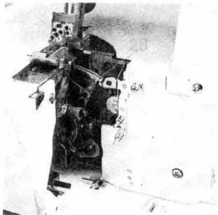
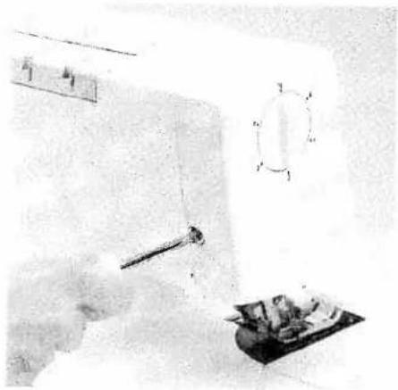
natural_image
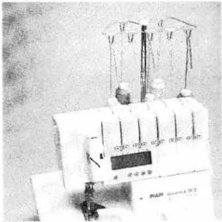
Exterior view of a PFAFF coverlock 4872 machine with control panel and digital display (no visible text or symbols on the device itself)Instruction Manual
text_image
Labeled diagram of a mechanical device with numbered components for identification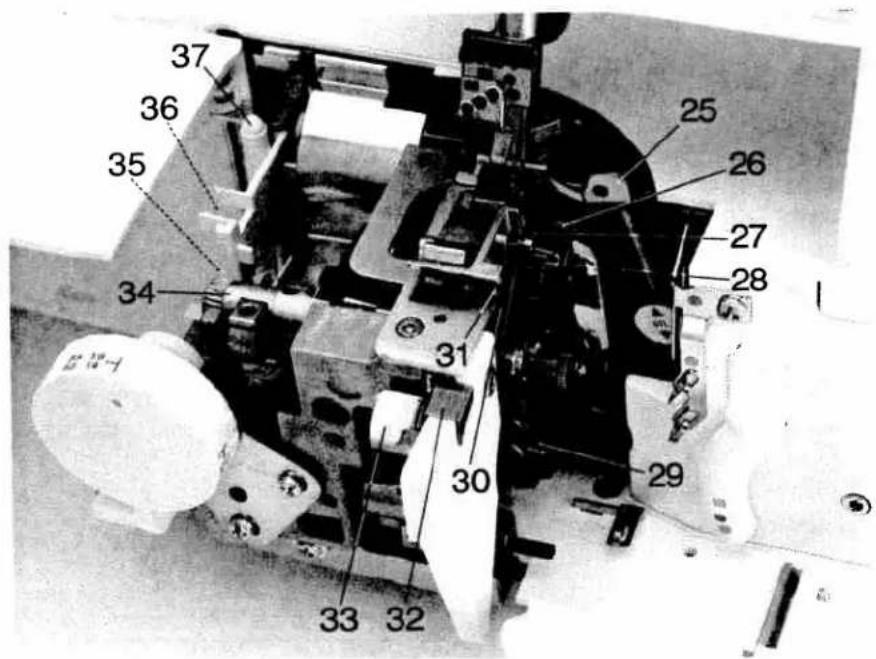
text_image
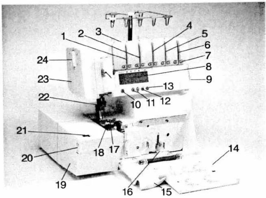
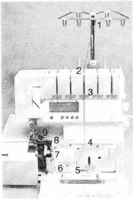
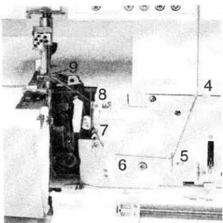
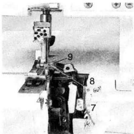
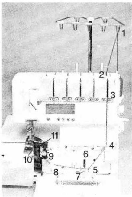
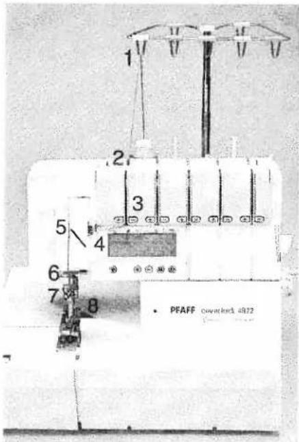
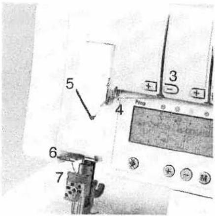
Labeled mechanical assembly diagram with numbered components for identificationParts of the coverlock 4872
1 Upper needle-thread tension
2 Upper needle-thread tension
3 Carry handle
4 Thread tension/upper looper thread
5 Thread tension/lower looper thread
6 Thread tension/two thread chainstitch looper/cover stich looper
7 Tension keys + and -
8 LCD display
9 Slide for sewing speed pre-selection
10 Tension release key
11 Program selection keys ⊕ and ⊖
12 Memory key M
13 Memory selection key P
14 Looper cover
15 Blade guard
16 Looper disengaging lever
17 Standard presser foot
18 Needle plate
19 Swivel plate
20 Adjusting knob for seam width
21 Seam width viewing window
22 Needle holder
23 Sewing light cover
24 Adjusting knob for the pressure foot pressure
25 Upper overedge looper
26 Lower overedge looper
27 Swiveling stitch width latch
28 Two-thread chainstitch looper
29 Threading aid for the two thread chainstitch looper/cover stitch looper
30 Movable upper blade
31 Fixed lower blade
32 Clamp spring for serging thread chains
33 Needle plate disengaging lever
34 Handwheel for lowering the upper blade
35 Tweezers
36 Converter
37 Allen key
For easier understanding of this instruction book please fold out this and the last page when reading.
Safety rules
For the United Kingdom only
The leads must definitely not be connected to the safety lead terminal I nor to a plug with three pins.
The wires in the mains lead are colored according to the following code:
Blue: Neutral
Brown: Live
As the colors of the wires in the mains lead of this appliance may not correspond with the color coding of the terminals in your plug, proceed as follows:
The wire which is colored blue must be connected to the terminal which is marked with the letter N or colored black. The wire which is colored brown must be connected to the terminal which is marked with the letter L or colored red.
Cut-off mains plugs are definitely not to be used, but disposed of immediately. Defective mains leads must be replaced completely.
Only 3 A spare fuses must be used as approved by ASTA according to BS 1362 and the fuse cover must be marked 3 A or with the corresponding color code.
The plug must never be used without fuse cover. Spare fuse covers are available from electrical suppliers or the PFAFF agencies.
Please also observe the general safety notes on page 2.
Important safety instructions
For Australia only
- If the supply cord is damaged, it must be replaced by the manufacturer or its service agent or a similarly qualified person in order to avoid a hazard.
The appliance is not intended for use by young children or infirm persons without supervision.
● Young children should be supervised to ensure that they do not play with the appliance.
Switch off or unplug the machine when leaving it unattended.
● Before servicing the appliance or replacing lamps, unplug the machine.
You will find the contents on page 4 and 5.
natural_image
Simple triangular warning symbol with no text or labels
natural_image
Simple geometric triangle shape with no text or symbolsImportant safety instructions
For the United States only
This sewing machine is designed and manufactured for HOUSEHOLD use only. When you use an electric appliance, the following basic safety precautions should always be adhered to: Read all instructions before using this sewing machine.
DANGER To reduce the risk of electric shock:
- The sewing machine should never be left unattended when plugged in. Always unplug this appliance from the electric outlet immediately after using and before cleaning.
- Always unplug before relamping. Replace bulb with same type rated 5 water.
- Do not reach for a sewing machine that has fallen into water. Unplug immediately.
- Do not place or store a sewing machine where it can fall or be pulled into a tub or sink. Do not place in or drop into water or other liquid.
WARNING To reduce the risk of burns, fire, electric shock, or injury to persons:
- Do not allow to be used as a toy. Great care is necessary when this sewing machine is used by or near children.
- Only use this sewing machine for its intended purpose as described in this manual. Only use attachments recommended by the manufacturer as contained in this manual.
- Never operate this sewing machine if it has a damaged cord or plug, if it is not working properly, if it has been dropped or damaged, or dropped into water. Return the appliance to the nearest authorized dealer or service center for examination, repair, electrical or mechanical adjustment.
- Never operate the sewing machine with any air openings blocked. Keep ventilation openings of the sewing machine and foot control free from the accumulation of lint, dust and loose cloth.
- Never drop or insert anything into any opening.
- Do not use out of doors.
- Do not operate where aerosol (spray) products are being used or where oxygen is being administered.
- To disconnect, turn all controls to off ("0") position, then remove plug from socket.
- Never operate on a soft surface such as a bed or couch where the air openings may be blocked.
- Do not unplug by pulling on cord. To unplug, hold the plug, not the cord.
- Keep fingers away from all moving parts. Special care is required around the sewing machine needle.
- Always use the proper needle plate. The wrong plate can cause the needle to break.
- Do not use bent or blunt needles. Only use needles recommended by the manufacturer.
- Do not pull or push fabric while stitching. It may deflect the needle, causing it to break.
- Switch the sewing machine off ("0") when making any adjustments in the needle area, such as threading needle, changing needle, threading bobbin, or changing presser foot, etc.
- Always unplug sewing machine from the electric outlet when removing covers, lubricating, or when making any other user servicing adjustments mentioned in the instruction manual.
- Hold plug when rewinding into cord reel. Do not allow plug to whip when rewinding.
Please also observe the general safety notes on Page 2.
KEEP THESE INSTRUCTIONS IN A SAFE PLACE
Notes on safety
Notes on safety for domestic sewing machines according to EN 60335-2-28 or IEC 335-2-28.
- The user must exercise adequate caution with regard to the up-and-down movement of the needle and constantly observe the sewing area during work.
- When leaving the machine, during maintenance work or when changing mechanical parts or accessories, always disconnect the machine from the main power by unplugging the lead cord from the wall outlet.
- The maximum permissible wattage for the sewing lamp is 5 watts.
- The tension of the belt drive must only be adjusted by a PFAFF mechanic.
- The machine must be put into operation according to the indications on the specification plate.
- Do not place any objects in openings on the machine.
- Do not use the sewing machine if:
- there is visible damage,
- its function is defective,
- it is wet, e.g. with condensation which can occur when a cold machine is brought into a warm room.
- Do not pull the mains plug out of the socket by its cord.
- If this appliance is used for another purpose than that intended or if it is wrongly operated, we cannot accept any liability for any damage caused.
- To avoid the risk of electric shock, do not open the machine. There are no parts inside the machine which the user can repair. This is the exclusive responsibility of our qualified service staff.
- Be sure to use only original PFAFF parts.
- The machine is designated for a mains
supply with a nominal voltage of +/- 10 % and a rated frequency of +/- 4 %.
- When used properly, the temperature of the outer components of a non-electronically controlled foot control can reach up to 85°C. Constant use at a low speed is therefore not permitted in order to avoid damage.
Environment
The recommended environment is: Ambient temperature 50^ F ( 10^ C) to 104^ F ( 40^ C)
Humidity 20 % to 80 %.
Storage temperature - 13° F (- 25° C) to + 140° F (60° C).
The machine is insensitive to interference, but it should not be used in the direct vicinity of electronic appliances such as radios, televisions, PCs, radio transmitters, etc. This machine is a high quality electronic-mechanical appliance, it is a machine for supervised use in the home. It should be operated in such a way that it is not subjected to: dust, severe dampness, direct sunlight, static electricity, heat-producing objects, corrosive chemicals or liquids. To permit adequate ventilation the machine must be kept unblocked and used on a firm and even surface.
Treatment
Always make sure not to damage your machine by knocking or dropping ist.
Cleaning
Housing and display:
To clean the housing, use a dry, clean and soft cloth which is free of lint. To remove any stubborn dirt, use a soft cloth with alcohol or paraffin.
Please Note!
Never use insecticides or chemical products such as petrol (gas) or thin chemicals to clean the housing.
Simple, up-to-date sewing
Congratulations! You have bought a high-quality product that provides unique advantages. Your new coverlock 4872 can take any material in its stride and will sew through thick and thin for you.
Your PFAFF coverlock features the very latest in design and technology, and it is just as easy to use as this instruction manual is to follow.
If you now take a bit of time to study the instruction manual nothing can go wrong.
It is certainly time well spent, since it is the only way to find out just what your machine can do and make full use of all its features.
If you have any further questions, just ask your PFAFF dealer. He is happy to be of service with any help or advice.
So now let's get started! We wish you many enjoyable hours creating your very own fashion ideas!
Contents
Page
Accessories 6
Accessories, special 68, 69
Accessory box....6
Adjusting the machine to Prog. 1, 2, 3, 4 .... 36, 37
Changing a spool on a threaded machine 24
Clamp spring....30
Cleaning the machine....65
Cone thread adapter....10
Converter, attaching 33
Cover stitch, important notes on sewing 51, 52
Differential feed....38, 39
Differential feed setting, changing and storing 42
Electrical connection....7
Electrical power master switch 7
Error 44
Foot control, connecting....7
Key functions....40
Language, choice 41
LCD Display 40
Light bulb (sewing lamp), changing 67
Looper cover 8
Lubricating the machine....65
Machine cover....6
Maintenance 65 - 67
Needle holder 13
Needle inserting tool 13
Needle plate disengaging lever 64
Needle plate, removing 64
Needle position....12
Needle threader....25
Needle, changing 13
Power table 37
Presser foot 11
Presser foot lifter....10
Presser foot pressure 29
Presser foot, changing 29
Program overview. 46 - 48
Programmable memories, deleting all 44
Programmable memories, notes on storing....44
Contents
Page
Rubber feet, cleaning 65
Safety instructions 1,2
Seam width adjusting knob 34
Seam width viewing window....34
Seam width, setting 34
Sewing light cover 67
Sewing problems and their solutions....70, 71
Sewing speed pre-selection....29
Specifications 72
Spool disc 10
Spool holder 7
Stitch formation correction measures....49-62
Stitch length adjustment knob....35
Stitch length setting, changing and storing 42
Stitch length, adjusting....35
Stitch programs programmable memories, activating 41
Stitch width latch, swiveling 32
Telescoping thread guide 9
Tension settings, changing and storing 43
Thread chain cutter....30
Thread chart 63
Thread guide, Clip-on....10
Thread net 9
Thread tension, setting....45
Thread unreeling disc....9
Threading aid for the two thread chainstitch looper/cover stitch looper....19,21
Threading paths/overview 26 - 28
Threading the lower overedge looper (yellow) 16, 17
Threading the needle(s) 22, 23
Threading the two thread chainstitch looper cover stitch looper (violet) ... 18 - 21
Threading the upper overedge looper (pink) 15
Threading, important note....24
Threading/Thread guides....14
Upper blade, changing....66
Upper blade, disengaging 31
Upper blade, securing 35
Waste container....8
natural_image
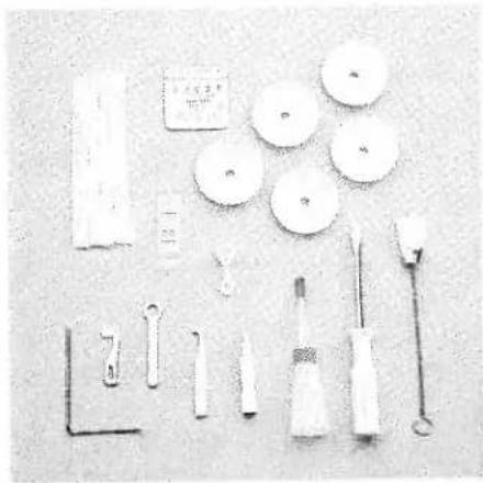
Collection of medical or laboratory tools including surgical instruments, clamps, and test tubes arranged on a plain surface (no visible text or labels)Accessory box
Open the accessory box 56 by gently pressing the bottom of the box inwards. The following accessories can be found in the box:
1 Overlock needle system EL X 705, cat. no. 2002
2 Thread nets (5)
3 Thread unreeling discs (5)
4 Screw driver
5 Needle threader
6 Wrench
7 Needle inserting tool
8 Replacement upper blade
9 Clip-on thread guide
10 Transparent presser foot (F) for cover stitch and two-thread chainstitch
11 Machine oil
12 Cleaning brush
13 Edge guide
Further accessories
The following accessories can be found behind the swivel plate 19:
1 Converter
2 Tweezers
3 Allen key

text_image
Technical diagram of a mechanical device with numbered components labeled 1, 2, and 3
text_image
PFAF coverlockMachine cover
The machine cover protects the machine from dust and dirt. When the sewing process is finished, push the telescoping thread guide 39 together. The spool stand 41 must be pushed to its full extent into the machine, regardless of whether a spool is attached. Place the cover over the machine. The accessories should be stored in the accessory box or compartments behind the swivel plate.

natural_image
Close-up of a white portable radio with ventilation grilles and a black plug, placed on a surface (no visible text or symbols)Operating instructions
Electrical connection
Connect the lead cord between the socket 45 of the machine and the wall outlet.
natural_image
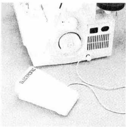
Close-up of a white electronic device with a circular button and connected cables (no visible text or symbols)Connecting the foot control
Connect the plug of the foot control to the connection socket 47 of the machine.
The pre-selected sewing speed range (see page 29) is regulated by pressing the foot control.
natural_image
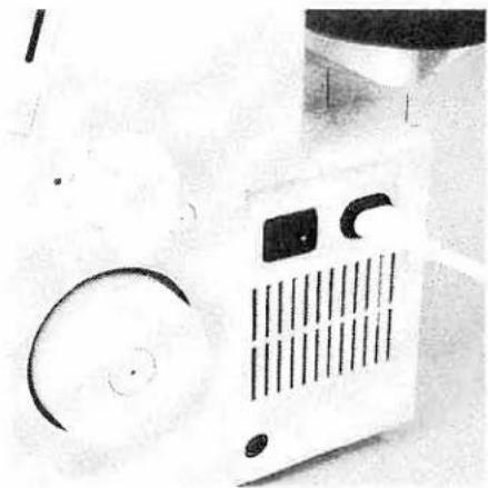
Close-up of a white portable air conditioner with ventilation grille and circular buttons (no visible text or symbols)Master switch
When you turn on the master switch 46 the sewing lamp is illuminated.
The machine is now operational.
Notes on safety
This appliance has a polarized plug (one blade wider than the other).
To reduce the risk of electric shock, this plug is intended to fit in a polarized outlet only one way. If the plug does not fit fully in the outlet, reverse the plug. If it still does not fit, contact a qualified electrician to install the proper outlet.
Do not modify the plug in any way.
For control sewing machine, foot controller type F 8 YC-485 has to be used.
text_image
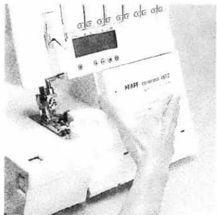
G E G E G F G E D E PTASS revenues d87Looper cover
Push the looper cover 14 fully to the right and then swivel it down. Five types of stitches and their threading paths are portrayed in color on the inside of the looper cover.
Note: The electricity supply of the machine is cut off as soon as the looper cover or swivel plate 19 is opened, for safety reasons, i.e. sewing with the machine is no longer possible.

text_image
PFAFF conmarkock 1072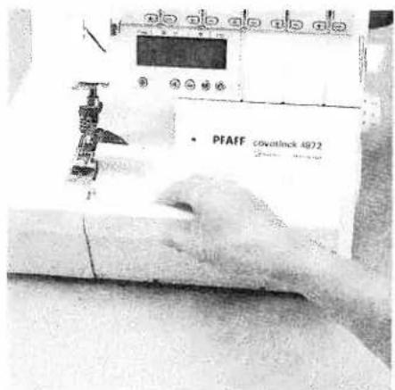
text_image
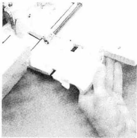
PFAFF coverlnck 4972Waste container
Insert the upper latch of the waste container 53 into the upper slot of the looper cover 14.
Apply pressure to the lower part of the container until the lower latches click into place in the lower slots of the looper cover.
To remove the waste container, repeat this procedure in the reverse order.
natural_image
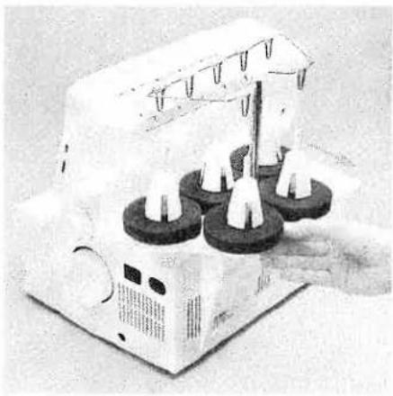
Illustration of a mechanical device with three circular components and a central rod, no visible text or symbols.Spool holder
Before placing thread cones/spools on machine you must pull the spool holder 41 fully away from the back of machine.

natural_image
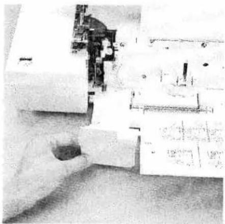
Person operating a sewing machine with a hand adjusting the top component (no visible text or symbols)Telescoping thread guide
Pull the telescoping thread guide 39 upwards to its highest position.
To ensure optimum thread feed, turn the telescoping parts slowly until you hear the locking balls click into place.
natural_image
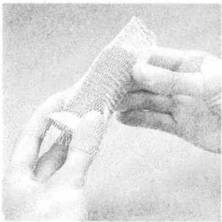
Close-up of a hand holding a textured, paper-like object with no visible text or symbolsThread net
Synthetic threads generally unwind too quickly from the thread spool. Thread nets have been included to allow easy use of these threads. Pull the thread net (located in the accessory box) over the spool from below. Place the spool on the spool holder catching the bottom of the thread net with the spool pin.

natural_image
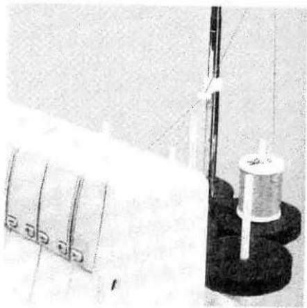
Mechanical testing setup with four circular components and a central cylindrical component (no visible text or symbols)Thread unreeling disc
The thread unreeling disc (in the accessory box) is used for small spools/spools with notched or rough ends. Place the spool on the spool pin 42. Place the thread unreeling disc on top of the spool. Make sure the spool disc 44 is used under the spool.

natural_image
Hand operating a precision testing machine with a tool inserted into a component (no visible text or symbols)Spool disc/cone thread adapter
It is advantageous to use the thread unree-ling disc 44 when sewing with large spools (5,000 - 10,000 m). To do this, place the cone thread adapter 43 onto the spool pin 42. With synthetic threads, the spool discs take up any play or surplus in the thread and guarantee excellent thread feed.
natural_image
Close-up of a textile machine with spools and a coiled spool, no visible text or symbolsClip-on thread guide
Use the clip-on thread guide accessory when sewing with decorative thread. Clip this onto the telescoping thread guide 39 and thread the machine as shown in the illustration. Use the thread net and the thread unreeling disc.
text_image
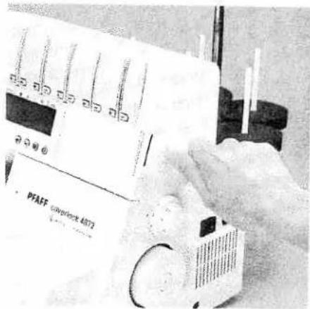
PFAEF powerlock 4073Presser foot lifter
The presser foot can be raised and lowered using the presser foot lifter 51. The maximum vertical lift of 6.5 mm for the presser foot for particularly thick fabrics can be achieved by pressing the presser foot lifter towards the rear.
natural_image
Close-up of a hand using a sewing machine to cut electrical components (no visible text or symbols)Once an initial thread chain has been created, the presser foot lifter no longer needs to be raised if you continue working with the same thread and presser foot. It is sufficient to gently lift the front part of the presser foot using your thumb. Slide the fabric under the raised part of the presser foot. The fabric is automatically taken up and fed into the machine when you activate the foot control.
natural_image
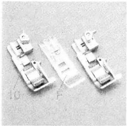
Three mechanical components with no visible text or symbolsPresser foot
With the standard presser foot 10 use the setting "A" of the spring-loaded presser foot latch for the cover stitch programs (Progs. 1, 2, 3), the two-thread chainstitch (Prog. 4), the 4-thread safety-stitch seam (Prog. 19) and the 5-thread safety-stitch seam (Prog. 20).
The transparent presser foot F from the accessories can also be used for the cover stitch (Prog. 1, 2, 3) and the two-thread chainstitch (Prog. 4).
For all other programs use the standard presser foot 10 and the setting "B" for the spring-loaded presser foot latch.

natural_image
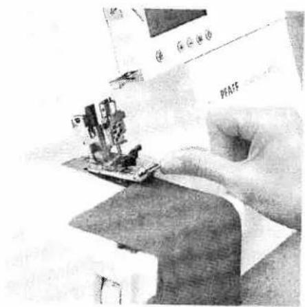
Close-up of a hand using a sewing machine to cut a printed object (no visible text or symbols)Changing the presser foot
Switch off the electrical power
To remove: Raise the needle(s) to the highest position by turning the handwheel towards you. Raise the presser foot and press the lever A at the rear of the presser foot holder. Pivot the presser foot clockwise until the front half of presser foot clears holder and remove by sliding foot away from you towards back of machine.
natural_image
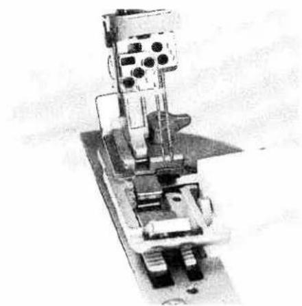
Mechanical assembly with gears and housing (no visible text or symbols)To attach: Place the presser foot behind and perpendicular to the sewing foot holder. Pivot the presser foot counterclockwise until the pin of the foot is directly under the presser foot holder clamp. Lower the presser foot lever and press lever A, if necessary, until the foot then clicks into place.
Check: Please lift the presser foot lever to ensure that the presser foot is properly locked into place.

text_image
R1 R2Needle position
This machine has 5 needle positions and can sew with a maximum of three needles at any one time. The needle positions concerned are L0, L1, L2, R1 and R2. The tightening/fastening screw is located directly above the corresponding needle.
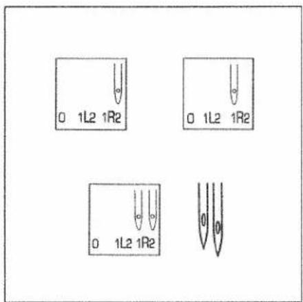
text_image
0 1L2 1R2 0 1L2 1R2 0 1L2 1R2The different needle positions are depicted in a schematic drawing in the instruction manual. Also refer to the examples above and below. Insert the needle(s) as shown on the LCD display.
Note: If both the needles R2 and R1 have been inserted, the left needle will be somewhat higher than the right needle.
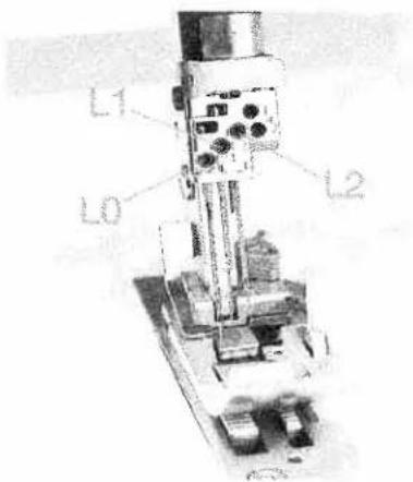
text_image
L1 L0 L2Note: If the needles L0, L1 and L2 have been inserted, the left needle will be the lowest of the three.
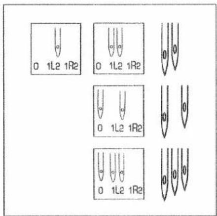
text_image
0 1L2 1R2 0 1L2 1R2 0 1L2 1R2 0 1L2 1R2 0 1L2 1R2If the needles L1 and L2 have been inserted, the left needle will be somewhat lower than the right needle.
If the needle L0 and L2 have been inserted, the left needle will also be lower than the right needle.
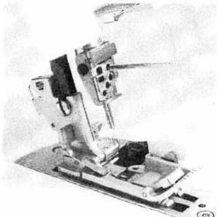
natural_image
Mechanical device with mounted components and a base plate (no visible text or symbols)Changing the needle
Switch off the electrical power
To remove: Lower the presser foot and move the needle(s) to the highest position by turning the handwheel. Push the needle inserting tool (from the accessory box 56) from below upward fully over the needle. Loosen the fastening screw of the needle (without removing it) with the Allen key and pull the needle down to remove.
natural_image
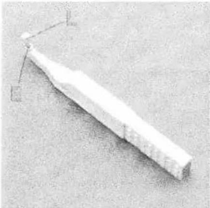
Simple 3D-rendered white object with a pointed base and small protrusions, no visible text or symbols.To insert: Insert the needle into the hole E of the needle inserting tool, so that the flat needle shank K faces the flat side L of the inserting tool. Now insert the needle fully into the holder and tighten the fastening screws. Remove the needle inserting tool.
natural_image
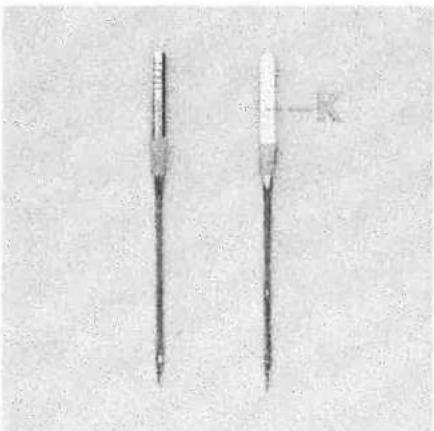
Two identical dental screw-like devices with no visible text or symbols on the bodyOverlock needle types EL X 705, cat. no. 2002 are required for this machine.
natural_image
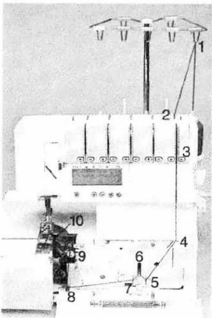
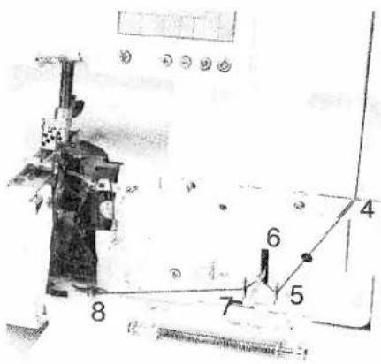
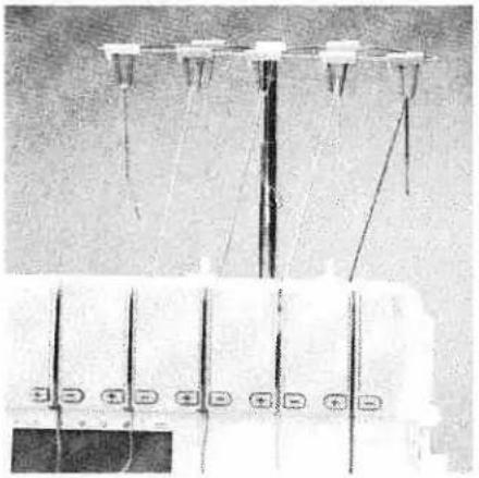
Laboratory equipment setup with digital display and mechanical components (no visible text or symbols)Threading the thread guides
Place the spools on the spool pins 42. You will find information on the thread net, thread unreeling disc, reel disc and cone thread adapter on pages 9 and 10. Thread through the thread guides 38 from the back to the front following the colored threading paths.

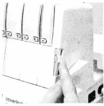
natural_image
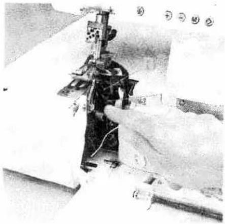
Black-and-white photo of a sewing machine with visible spools and base (no text or symbols)Pull the carry handle 3 upwards. Thread through the underside of the carry handle and through the rear thread guides 52 using both hands to pull the thread down until it slips under the thread guide. Guide the thread through the tension discs and pull it down until it is positioned firmly between the tension discs. Return the carry handle to its original position.

text_image
Diagram of a mechanical or electrical component with numbered parts labeled ① to ⑤Note:
Thread in a sequence of 1 to 5.
text_image
Technical diagram of a sewing machine with numbered components and labeled partsThreading the upper overedge looper (pink)
Turn the handwheel towards you until the upper overedge looper 25 is in its highest position. Thread in a sequence of 1 to 9.
Note:
To make this task easier, use the tweezers which can be found behind the swivel plate.
text_image
Technical diagram of a mechanical device with numbered components, likely an electrical or machine assembly.Thread through the thread guides 1 to 8, which are marked with a pink dot.
text_image
Technical diagram of a mechanical device with numbered components labeled 7, 8, and 9Thread from the front through the eye of the upper overedge looper 9. Pull approximately 4" (10 cm) of thread through the looper and place it to the left under the presser foot.

text_image
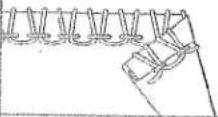
26Threading the lower overedge looper (yellow)
Turn the handwheel towards you until the lower overedge looper 26 is on the extreme right.

text_image
Labeled diagram of a sewing machine with numbered parts for identificationThread in a sequence of 1 to 10.
Note:
To make this task easier, use the tweezers which can be found behind the swivel plate.

text_image
5 6 7 8Thread through the thread guides 1 to 8, marked yellow.
natural_image
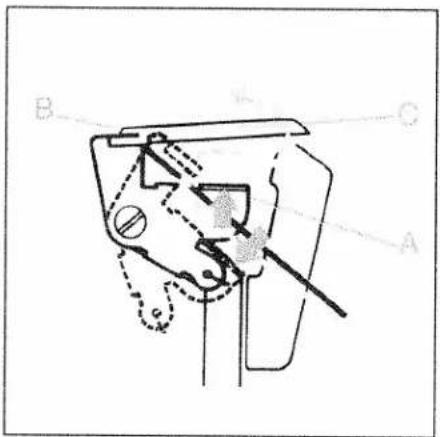
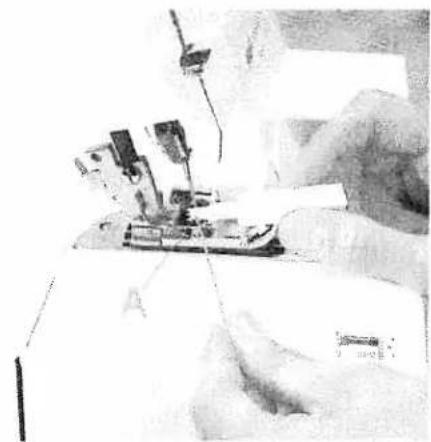
Close-up of a sewing machine needle stitching fabric, with hands operating the mechanism (no visible text or symbols)Press the lever A downwards and hook the thread into the guide B. Please also refer to the drawing below.
Note:
The lever returns automatically to its position as soon as you start sewing.
text_image
B A CThread from the front through the eye of the lower overedge looper C (= threading point 10).

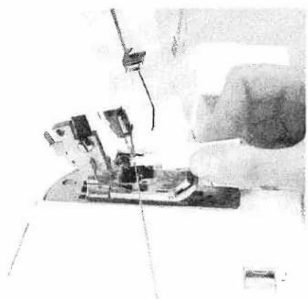
natural_image
Black-and-white photo of a mechanical device with visible components and wiring (no text or symbols)Pull approximately 4" (10 cm) of thread through the looper and place it to the left under the presser foot.
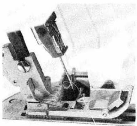
natural_image
Black-and-white photo of a mechanical device with visible components and no readable text or symbolsThreading the two thread chainstitch looper and cover stitch looper (violet)
Turn the handwheel towards you until the two thread chainstitch looper 28 is on the extreme right.
text_image
Technical diagram of a sewing machine with numbered components for identificationThread in a sequence of 1 to 11.
Note:
To make this task easier, use the tweezers which can be found behind the swivel plate.

text_image
Technical diagram of a machine tool with numbered components and control panelThread the thread guides which are marked with a violet square in a sequence of 1 to 9.
natural_image
Interior view of a spacecraft or spacecraft with labeled components (A, B), no visible text or symbols beyond labelsPush the lever A upward and hook the thread into the slot B. Also refer to the drawing below.
Note:
The lever returns automatically to its position as soon as you start sewing.
text_image
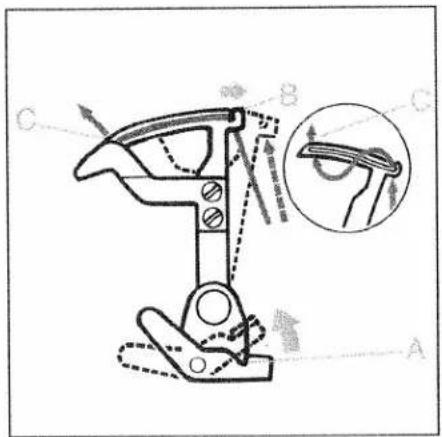
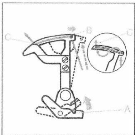
Technical diagram of a mechanical clamp or bracket with labeled parts A, B, C and an inset showing a close-up view of the clamp.Thread from the front through the eye C of the two thread chainstitch looper and the cover stitch looper.

natural_image
Close-up of mechanical components with no visible text or symbolsPull approximately 4" (10 cm) of thread through the looper and place it to the left under the presser foot.
natural_image
Black-and-white photo of a mechanical device with attached components and no visible text or symbolsException:
Threading the two thread chainstitch looper and cover stitch looper for the cover stitch (violet)
(Prog. 1, 2, 3)
Turn the handwheel towards you until the two thread chainstitch looper 28 is on the extreme right.
text_image
Technical diagram of a sewing machine with numbered components for identificationThread in a sequence of 1 to 10.
Note:
To make this task easier, use the tweezers which can be found behind the swivel plate.
text_image
Technical diagram with numbered components and labeled parts, likely from an engineering or mechanical drawing.Thread the thread guides, as shown in the diagram, in a sequence of 1 to 8. Some of the threads guides are marked with a violet square.

natural_image
Person in full-body suit standing on a platform, possibly a spacecraft or industrial equipment (no visible text or symbols)Press lever A upward and hook the thread into slot B. Also refer to the drawing below.
Note: The lever returns automatically to its position as soon as you start sewing.
text_image
Technical diagram of a mechanical clamp or clamp device with labeled parts A, B, C and an inset showing a magnified view of the clamp.Thread from the front through the eye of the two-thread chainstitch looper and the cover stitch looper C.
natural_image
Black-and-white photo of a person operating machinery with visible wiring and components (no text or symbols)Pull approximately 4" (10 cm) of thread through the looper and place it to the left under the presser foot.
text_image
1 2 3 4 5 6 7 8 PFAFF Geyntelock 4872Threading the needles
Thread in a sequence of 1 to 8.
Note:
To make this task easier, use the tweezers which can be found behind the swivel plate.
text_image
5 3 + - + 4 Proo 6 7The thread must be guided through the lower slot of thread guide 5.
natural_image
Cross-sectional view of a mechanical device with internal components (no visible text or symbols)Pull approximately 4" (10 cm) of thread through the looper and place it to the left under the presser foot (if necessary activate tension release key 10, also see page 40).

text_image
1 2 3 4 5 6 7 8 PFAFF CLOVERA 1072Exception:
Threading needle L2 when sewing a 5-thread safety-stitch seam (Prog. 20), a 4-thread safety-stitch seam (Prog. 19) and a 2-thread chainstitch (Prog. 4)
Thread in a sequence of 1 to 8.
Note:
To make this task easier, use the tweezers which can be found behind the swivel plate.

text_image
Diagram of a sewing machine with numbered parts and control buttons, likely for sewing or sewing process.The thread must be guided through the upper slot of the thread guide 5.

natural_image
Cross-sectional view of a mechanical device with internal components (no visible text or symbols)Pull approximately 4" (10 cm) of thread through the looper and place it to the left under the presser foot (if necessary activate tension release key 10, also see page 40).

natural_image
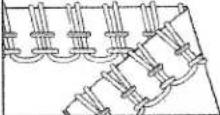
Technical line drawing of a mechanical assembly with no visible text or symbolsImportant note on threading
The needle(s) must always be threaded last so that the needle threads do not run under the looper thread as seen in drawing 1, but instead over the looper thread as depicted in drawing 2. Should this sequence not be followed, thread breakage or missed stitches can occur.

natural_image
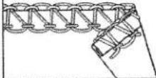
Technical line drawing of a mechanical assembly with no visible text or symbolsIf the looper threads break, you must pull the needle threads out of the needle, rethread the looper thread and then rethread the needle threads.
natural_image
Electrical wiring diagram showing multiple connection points and wires (no text or labels visible)Changing a spool on a threaded machine
Cut the threads off close to the spool and replace with new spools. Tie together the threads which are still in the machine with the new threads, and pull the threads out of the needles. Activate tension release key 10 (also refer to page 40). Pull on the needle threads until the knots are about 6 inches (15 cm) past the last thread guide in front of the needles. Cut the knots off and pull the threads through the respective needle eyes. The looper threads can be pulled continuously past the looper eye and placed to the left underneath the presser foot.
natural_image
Close-up of a sewing machine needle stitching fabric, no visible text or symbolsNeedle threader
Move the needle(s) into the highest position and lower the presser foot. Place the thread from right to left in notch A of the needle threader (to be found in the accessory box). One of the two triangles must point upwards.
natural_image
Close-up of a sewing machine needle stitching fabric, no visible text or symbolsPlace the needle threader onto the front groove of the needle. Slide the needle threader down to the needle eye and press it lightly against the needle.
natural_image
Mechanical device with articulated arms and wiring, no visible text or symbolsA small metal pin is pushed through the needle eye and the needle is automatically threaded. Thread loops must be pulled to the back.
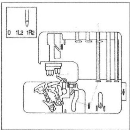
Overview of the threading paths and threading sequences
text_image
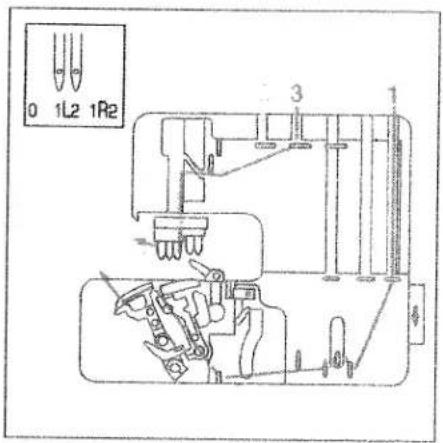
0 1L2 1R2 3Program 01: cover stich, 2-needle, narrow

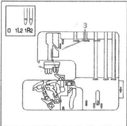
text_image
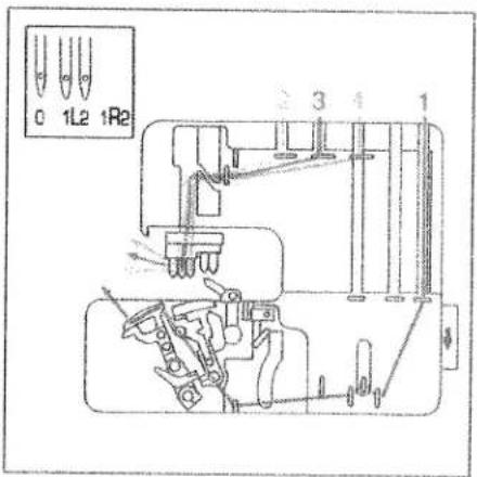
0 1L2 1R2 3 1Program 02: cover stitch, 2-needle, wide
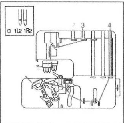
text_image
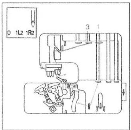
0 1L2 1R2 3 4 1Program 03: cover stitch, 3-needle 4-thread

text_image
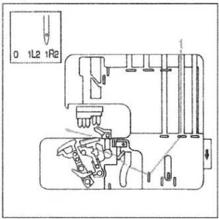
0 1L2 1R2 1Program 04: 2-thread chainstitch
Overview of the threading paths and threading sequences

text_image
0 1L2 1R2 ?Program 05:
2-thread flatlock, narrow
Program 07:
narrow 2-thread serging
Program 08:
2-thread flat hem
Program 09:
folded 2-thread rolled hem
text_image
0 1L2 1R2Program 06:
2-thread flatlock, wide
text_image
0 1L2 1R2 3Program 10:
3-thread overedge, narrow
Program 16:
3-thread flat hem
Program 17:
folded 3-thread rolled hem
Program 13:
3-thread flatlock, narrow
text_image
0 1L2 1R2Program 11:
3-thread overedge, wide
Program 12:
wide 3-thread serging seam
Program 14:
3-thread flatlock, wide
Overview of the threading paths and threading sequences
text_image
0 1L2 1R2 3Program 15:
2-needle 3-thread overedge seam

text_image
0 1L2 1R2Program 18:
4-thread overedge seam
text_image
0 1L2 1R2 3 4Program 19:
4-thread safety-stitch seam

text_image
0 1L2 1R2 4 1 5Program 20:
5-thread safety-stitch seam
natural_image
Close-up of a hand holding a white object with multiple square buttons, next to a device casing (no visible text or symbols)Sewing speed pre-selection
Using sewing-speed pre-selection slide 9, the maximum speed can be adjusted anywhere between 700 rev/min. and 1500 rev/min.
text_image
1 2 3 4 5 6 7 8Presser foot pressure
The pre-set presser foot pressure on the machine is suitable for medium-heavy fabrics. The presser foot pressure does not need to be adjusted for most fabrics. If you are working with light or heavy fabrics then you may need to adjust the pressure. In this case, 6 setting positions are available which you can select using the adjusting knob for the presser foot pressure 24. The standard setting is "N".

natural_image
Black-and-white photo of a vintage sewing machine in the foreground, with no visible text or symbols.Thread chain cutter
After finishing the seam, sew an approx. 6" - 8" (15 -20 cm) long thread chain. Pull the thread chain from the back to the front over the thread chain cutter 40. This will cut off the thread chain.
natural_image
Close-up of a sewing machine needle stitching fabric (no visible text or symbols)Clamp spring for serging thread chain 32
Using this feature you can serge the thread chain at the start of the fabric, by pulling it into the seam. Stitch off a minimum 4" (10 cm) long thread chain and raise the presser foot. Remove the thread chain carefully from the swiveling stitch width latch 27. Pull the thread chain forwards and clamp it under the spring.
natural_image
Close-up of a sewing machine needle stitching fabric, no visible text or symbolsPlace the fabric right in front of the needle(s). If necessary, make an approx. 1.5" (3 cm) cut into the fabric along the cut-line using a pair of scissors. Lower the presser foot and start sewing. The thread chain pulls automatically into the inside of the seam.
Note:
This feature cannot be used for either the five-thread safety-stitch seam, the four-thread safety-stitch seam, the two-thread chainstitch or for the rolled hem.

natural_image
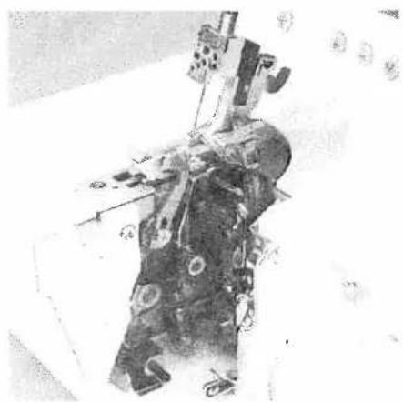
Close-up of a mechanical device with visible internal components and a hand adjusting it (no text or symbols)Disengaging the upper blade Switch off the electrical power
Move the movable upper blade 30 into its highest position by turning the handwheel. Remove the waste container and open the looper cover and the swivel plate. Now turn the handwheel fully to the right to lower the upper blade 34.
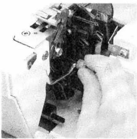
natural_image
Interior view of a mechanical or electrical device with multiple components and wiring (no visible text or symbols)Turn the knob towards you until the upper blades clicks into place below. The upper blade is now disengaged.
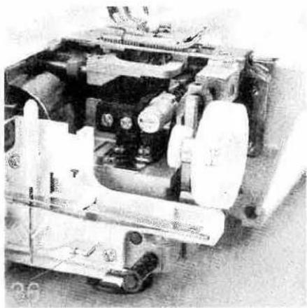
natural_image
Mechanical assembly with gears and housing (no visible text or symbols)Engaging the upper blade
Push the knob for lowering the upper blade to the right and swivel back the blade until it clicks into the operating position again. Close the looper cover and the swivel plate and remount the waste container.

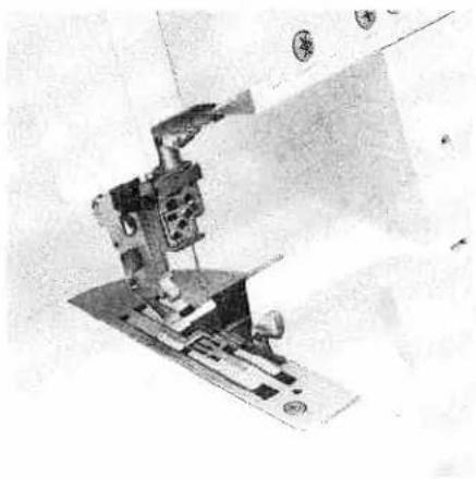
natural_image
Mechanical sewing machine with needle and base mount (no visible text or symbols)Swiveling stitch width latch
For standard overlock seams:
The swiveling stitch width latch 27 remains in the basic position when sewing all types of standard overlock seams (exception: program 1, 2, 3, 4).
natural_image
Close-up of hands assembling or adjusting a mechanical component (no visible text or symbols)For rolled hems:
Pull the knob (A) to the right and swivel the swiveling stitch width latch 27 downwards.
natural_image
Mechanical sewing machine in operation, no visible text or symbolsThis setting allows you to sew all types of rolled hems.
natural_image
Interior view of a mechanical device with visible gears and shafts (no text or symbols)Attaching the converter
Switch off the electrical power
The converter 36 must be attached for all two-thread seams (exception: Program 4) and the two-needle three thread closing seam. Open the swivel plate and remove the converter 36 from its storage space.
natural_image
Technical illustration of a mechanical assembly with no visible text or symbolsPosition the upper overedge looper 25 right next to the needle by turning the handwheel towards you.

natural_image
Close-up of a hand operating a sewing machine tool (no visible text or symbols)Push the tip of the converter into the back side of the eye of the upper overedge looper until it clicks into place and push the converter onto the overedge looper bracket.

natural_image
Close-up of a hand operating a sewing machine with circuit board (no visible text or symbols)To remove the converter, gently push the point of the converter from the eye of the upper overedge looper. You can now remove the converter by pulling it upwards from the overedge looper bracket.

natural_image
Close-up of hands operating a sewing machine needle (no visible text or symbols)
natural_image
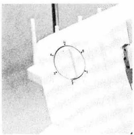
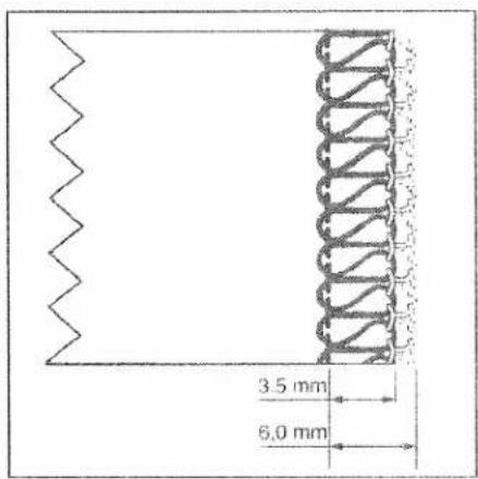
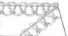
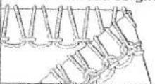
Two schematic diagrams of solenoid coil structures labeled A and B, showing internal winding patterns (no text or symbols beyond labels)Setting the seam width
The required seam width can be adjusted anywhere between 3.5 and 6 mm by turning the adjusting knob for seam width 20. The setting can be seen at the viewing window 21. The two-thread chainstitch is sewn with a clearance of 6.5 to 9 mm.
Illustration A: Should loops project out of the workpiece, move the movable upper blade 30 to the right by turning the seam width adjusting knob upwards.
Illustration B: Should the stitching be too tight, move the movable upper blade to the left by turning the seam width adjusting knob downwards.
text_image
3.5 mm 6.0 mm
text_image
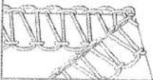
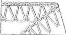
5.5 mm 8.0 mmNote:
The seam width settings 3.5 mm and 6.0 mm are only relevant for needle R2. This set-value is increased by 2.0 mm when using needle R1, i.e. you have a seam width which is completely adjustable from 5.5 mm to 8.0 mm.

natural_image
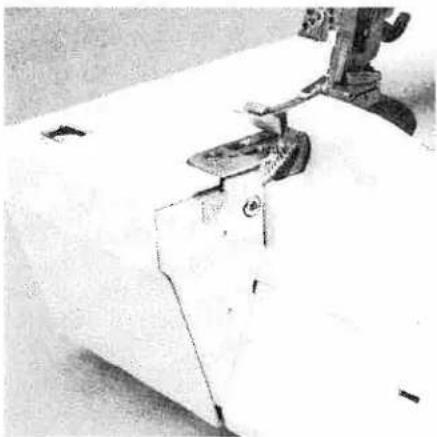
Close-up of a mechanical device with hands adjusting parts (no visible text or symbols)Securing the upper blade
Switch off the master switch
It is recommended to secure the movable upper blade 30 before sewing heavy fabrics. Raise the needle(s) to its highest position and open the swivel plate. Tighten the screw fully using the Allen key. This screw should always be slightly loosened again after sewing heavy fabrics.
Note:
The seam width can no longer be adjusted once the upper blade is secured.

natural_image
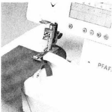
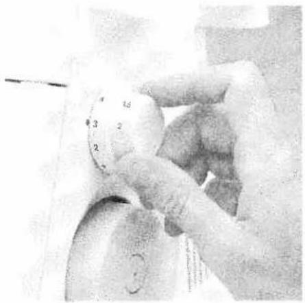
Close-up of a gloved hand holding a circular gauge or dial, with no visible text or symbols.Adjusting the stitch length
You can set the desired stitch length between 0.5 mm to 4.0 mm by turning the stitch length adjustment knob 50.
Note:
For the two-thread chainstitch, the setting should be 3.0 or higher.
natural_image
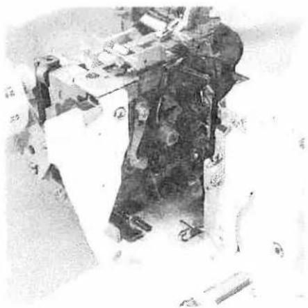
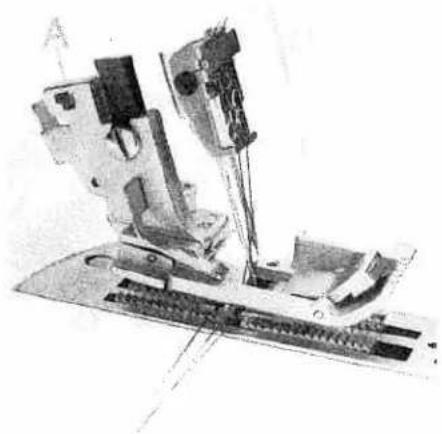
Close-up of a hand operating a sewing machine tool on a wooden surface (no visible text or symbols)Adjusting the machine to the cover stitch (Prog. 1, 2, 3) and two thread chainstitch (Prog. 4)
This is only necessary if you do not want to trim the fabric edge. Insert the needle(s) according to the LCD display (see page 13). Open the looper cover and remove the blade guard 15 by pulling it towards you.
Lower the swiveling stitch width latch (see page 32) and disengage the upper blade (see page 31). Ensure that the upper blade is disengaged by turning the handwheel.
natural_image
Cross-sectional view of a mechanical device with numbered components (no readable text or symbols)Disengage the upper overedge looper. Move the upper overedge looper 25 into its lowest position by turning the handwheel.

natural_image
Close-up of a mechanical assembly with mounting holes and a tool (no visible text or symbols)Move the looper disengaging lever 16 to the left. Ensure that the looper is disengaged by turning the handwheel.
Thread the two thread chainstitch looper and the cover stitch looper (see pages 18 to 21) and then the needle(s) (see page 22 and 23).

natural_image
Close-up of a sewing machine needle stitching fabric, with no visible text or symbols on the device itself.Press the power table 57 downwards into the designated slot on the looper cover. Close looper cover.
Note:
Please ensure that the upper overedge looper is disengaged before attaching the power table 57.
natural_image
Close-up of a hand operating a sewing machine with visible mechanical components (no text or symbols)To return the machine to its previous settings after sewing with the cover stitch or two thread chainstitch.
Open the looper cover and remove the power table.
natural_image
Close-up of a hand using a sewing machine to adjust or install a small electronic component (no visible text or symbols)Move the looper disengaging lever to the right, thus re-engaging the upper overedge looper.
Bring the swiveling stitch width latch into the basic position (see page 32) and engage the upper blade (see page 31).
Push the blade guard into the looper cover and close it.

natural_image
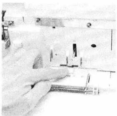
Mechanical device with labeled parts A and B, no visible text or symbols on the device itselfDifferential feed
The differential feed consists of two feed dogs (A + B), one behind the other, which feed the fabric. The movement of the front feed dog (A) and thus the amount of material to be fed can be regulated using the regulator wheel 49. The setting range is between 0.5 and 2.0.
The standard setting is 1.0, where the movement of the front feed dog (A) is synchronized with the rear feed dog (B). This means that the front feed dog feeds the same amount of fabric as the rear feed dog.
Note:
The function of the differential feed is independent of the set stitch length and the type of fabric being used.
natural_image
Close-up of hands adjusting a circular dial with measurement markings (no visible text or symbols)Set the regulator wheel for the differential feed 49 to 0.5. Here the front feed dog feeds half as fast as the rear feed dog. This means that the front feed dog feeds only half as much fabric as the rear feed dog, causing the fabric to stretch.
natural_image
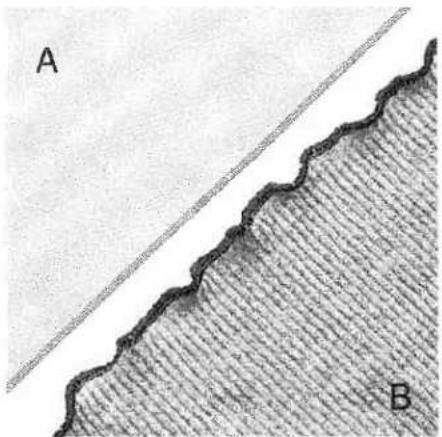
Cross-sectional diagram showing a wavy boundary and a diagonal line, with labeled points A and B (no text or symbols beyond labels)Here you will avoid ruffling in the seam when working with very light fabrics, such as silk and taffeta. Instead, a smooth seam (A) will be achieved.
You can also achieve fashionable effects with the differential feed dog, for example the wavelike effect when using a rib knit (B).
natural_image
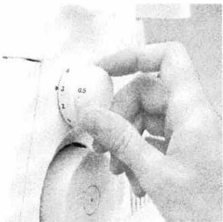
Close-up of a gloved hand holding a circular gauge or dial, with no visible text or symbols.Set the regulator wheel for the differential feed 49 to 2.0.
Here the front feed dog feeds twice as fast as the rear feed dog. This means that the front feed dog feeds twice as much fabric as the rear feed dog, causing the material to gather.

natural_image
Close-up of two textured fabric strips labeled A and B, showing parallel grooves and a textured surface (no text or symbols)Here you will avoid stretching in the seam when working with knitwear, such as jerseys or gathered fabrics. Instead, a smooth seam (A) will be achieved.
You can also achieve fashionable effects with the differential feed dog, for example the gathering effect when using very light fabrics (B).
The following table contains information on the differential feed settings. However, you should always test your setting first on a piece of scrap fabric.
| Type of fabric / effect | Differential feed setting | ||
| gather <2> | normal <1> | stretch <0.5> | |
| Very light fabrics: silk, satin, poplin, taffeta, linings. | ● | ● | |
| Normal fabrics: light and medium-heavy cottons, fine cords, thermal-wear. | ● | ||
| Light knitwear: jerseys, polo fabrics, cut-pile pullovers, tricot, fine knitwear and gathered fabrics. | ● | ● | |
| Heavy knitwear: sweatshirt fleece, heavy gathered fabrics, heavy knitwear. | ● | ||
| Stretch - wavelike effect: medium and light knitwear, jerseys, knitwear, ruffled sleeve and collar edges, skirt hems, dense stitch lengths. | ● | ||
| Gathering: ruffling light materials and lace, seam allowances for curves, arches on blouses, shirts, skirts, round pockets, flaps, stretching or gentle ruffling of arched sleeves (shoulders), sleeve widths for cuffs or gathered fabrics. | ● | ||
text_image
Prog 1 Cover Stick 2 3 4 2-Nadel schmal 5 6 7 8 9 10 5 6 7 8 9 10 ⊕ + - M ◆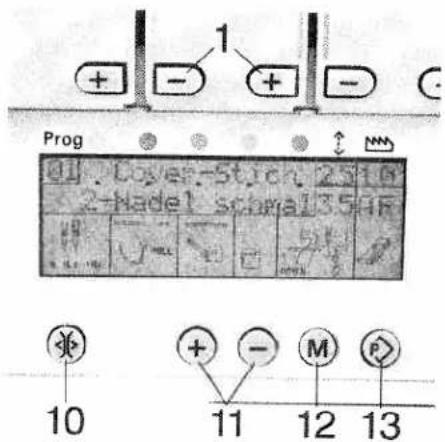
text_image
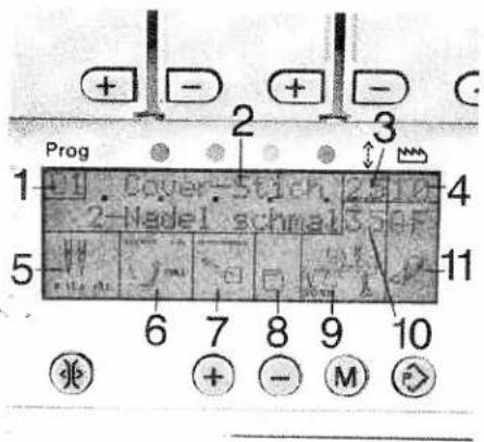
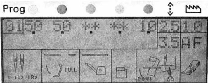
1 + - + - Prog 1 Cover-Stick 25 10 2-hadel screw 35 4F 10 11 12 13LCD Display
1 Program no.
2 Name of stitch
3 Stitch length in mm
4 Differential feed setting
5 Needle position
6 Swiveling stitch width latch position stitch width latch in basic position

stitch width latch lowered
7 Upper overedge looper position

looper engaged

looper lowered

Converter engaged
8 Power table position

with power table

without power table
9 Upper blade position

upper blade engaged

upper blade disengaged
10 Seam width in mm
11 Setting of spring presser foot latch A or B - As long as E appears in the display, the transparent presser foot from the accessories can also be used.
Key functions
1 Tension keys + and -
For increasing and reducing thread tension
10 Tension release key
When this key is pressed and held, the thread tensions are released. This allows the thread chain to be easily pulled from the machine. When the key is released, the thread tensions reset for the programm selected.
11 Program selection key + and -
The desired program can be selected with these keys. There are 20 programs preset for your use. If the keys are kept pressed down, the programs will automatically run on. When the machine is switched off and back on, the last program sewn will appear.
12 Memory key M: The adjusted settings for stitch length, differential feed and thread tension can be stored using this key.
13 Memory selection key P: With this key, you can activate the program memory and the programmable memories A, B and C.
text_image
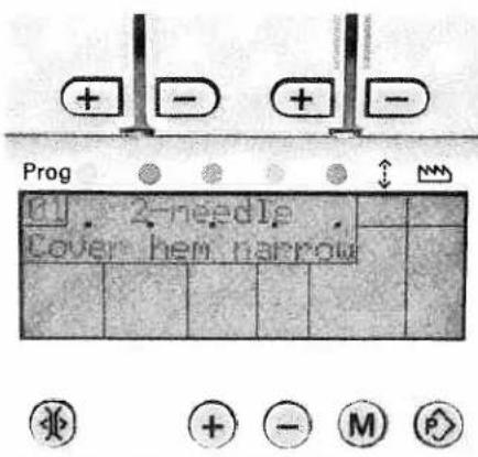
Prog 2-pin Cover hem harrowChoice of language
The following languages can be selected: Czech, Danish, German, English, Spanish, French, Italian, Dutch, Polish, and Portuguese.
Keep both the + and - keys pressed down simultaneously and switch on the machine. The desired language can then be selected using the + and - keys. Program the desired language by pressing the memory key M once.
Each description will then appear in the selected language.
text_image
Prog 0150 50 ** * 10 2.5 10 3.5 AF 1L2 IR2 PULL DOWNII


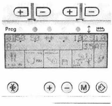
Activating the stitch programs programmable memories
Activate the desired program using the program selection keys + and -. By pressing the memory selection key P once, you can activate the program memory. The set tensions appear on the display. The tensions, marked with ** are not valid for this program, i.e. these tensions must not be threaded. If there is no change made within 10 seconds, the name of the program will appear on the display again.
text_image
Preg 25 1.8 3.5 PF 40 POLI 50 + - M P
text_image
Prog 12 2 3 5 3 F + - M PChanging and storing the stitch length setting
Activate the desired program using the program selection keys + and -. Press the memory selection key P until the memories A, B or C appear on the display. By pressing the memory key M, the stitch length display
will flash. Using the program selection key +, you can adjust the stitch length. The changed stitch length can now be stored by pressing the memory key M.
text_image
Prog 10 50 25 10 3.5 A P + - + -
text_image
Prog + - + - A 2.5 L 3.5 D F - - - + + - M PChanging and storing the differential feed setting
Activate the desired program using the program selection keys + and -. Press the memory selection key P until the memories A, B or C appear on the display. By pressing the memory key M, the stitch length display will flash. Using the program selection key -, activate the differential feed display i.e. the
differential feed display will flash. Using the program selection key +, the differential feed can now be adjusted and then stored by pressing the memory key M.

text_image
Prog + - + - ↑ ↑ 25 10 3.5 AF + - M + + - M PChanging and storing the stitch length, differential feed and tension settings
Activate the desired program using the program selection keys + and -. Press the memory selection key P until the memories A, B or C appear on the display. By pressing the memory key M, the stitch length display will flash. Using the program selection key +, the stitch length can be changed. Using the program selection key -, the differential feed display will be activated and the differential feed can be changed using the program selection key +. The tension settings can be adjusted in increments of two using the tension keys + and -. The adjusted settings can be stored using the memory key M.

text_image
Prog 41 42 43 * * 98 518 A 3.5 A P H 2 1 + - M P -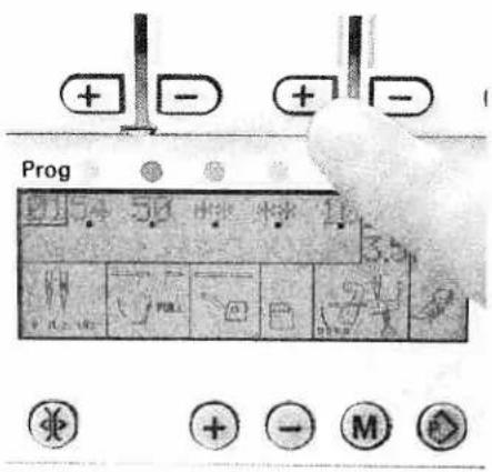
text_image
Prog + - + -Storing only adjusted tension settings
Select the desired memory using the memory selection key P. Change the tension and press the memory key M twice.
Adjusting the tension without storing
If you would like to adjust the tension e.g. whilst sewing, without having to store this adjustment, simply press one of the tension keys + or -. All tensions can now be adjusted as desired.
Notes on storing in programmable memories
If the memory selection key P is not pressed while storing, the new settings will automatically be stored in a free memory using the memory key M.
If all the memories are occupied, the new settings will not be accepted. Single memories can not be deleted, only overwritten.
Deleting all the programmable memories
Switch off the machine. Press the program selection keys + and - as well as the memory key M. Keep the keys depressed and switch the machine back on. All the memories will be deleted.

text_image
Prog . ERROR 2 . . . ↓ M M


Error
If one of the stepping motors for the thread tension adjustment fails, "ERROR" will appear on the display. Error 2 means: the second stepping motor of the green needle thread tension does not function. If "ERROR" appears on the display after having switched the machine off and back on again, your machine must be taken to your authorized PFAFF dealer for service.

natural_image
Industrial sewing machine with digital display and control buttons (no visible text or symbols)Setting thread tension
This machine offers automatic setting of the thread tension for each separate program.
As the type of fabric, thread quality and needle size vary and can greatly influence the seam quality, the setting of the thread tensions may require slight adjustments.
Changing the tension settings is described on page 43.
Tip
Always sew off a test seam on a piece of scrap fabric and check the thread loops. Adjust the thread tension if necessary (see pages 49 - 62).
| Program overview | ||
| Program | Area of application | |
Program 01Cover stitch 2-needle, narrow | Sewing hems and fancy stitches. | |
Program 02Cover stitch 2-Nadel, wide | Sewing hems and fancy stitches. | |
Program 03Cover stitch 3-needle, 4-thread | Sewing hems and fancy stitch. | |
Program 04Two thread chainstitch | Joining fabric layers where a traditionalpressed-open seam is required. Also workswell as a basting stitch for test-fittinggarments. | |
Program 052-thread flatlock, narrow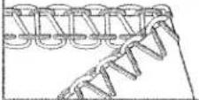 | Serging light fabrics. Joining stretch fabricswith a flatlock seam. | |
Program 062-thread flatlock, wide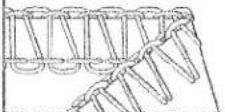 | Serging medium-heavy fabrics. Joiningstretch fabrics with a flatlock seam. | |
Program 072-thread narrow serging seam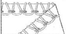 | Serging light fabrics. | |
| Program overview | Area of application | |
| Program | ||
| Program 082-thread flat hem | Serging very light fabrics. Decorative edges. | |
 | ||
| Program 09Folded 2-thread rolled hem | Serging very light fabrics. Decorative edges. | |
 | ||
| Program 103-thread overedge narrow | Serging light (easily frayed) fabrics. | |
 | ||
| Program 113-thread overedge wide | Serging tightly woven (easily frayed) fabrics. | |
 | ||
| Program 12wide 3-thread serging seam | Serging tightly woven (non-fraying) fabrics. | |
 | ||
| Program 133-thread flatlock, narrow | Serging medium-heavy fabrics. Joining stretch fabrics with a flatlock seam and decorative edges. | |
 | ||
| Program 143-thread flatlock, wide | Joining fabrics with a flatlock seam and decorative edges. | |
 | ||
| Program overview | |
| Program | Area of application |
| Program 152-needle, 3-thread overedge seam | Joining and simultaneous serging of light,very stretchy fabrics. |
 | |
| Program 163-thread flat hem | Serging light to medium-heavy fabrics.Decorative edges. |
 | |
| Program 17Folded 3-thread rolled hem | Serging light to medium-heavy fabrics.Decorative edges. |
 | |
| Program 184-thread overedge seam | Joining and simultaneous serging of all-fabrics, in particular stretchy fabrics. |
 | |
| Program 19Wide 4-thread safety-stitch seam | Joining and simultaneous serging oftightly woven fabrics. |
 | |
| Program 20Wide 5-thread safety-stitch seam | Joining and simultaneous serging oftightly woven fabrics. |
 | |
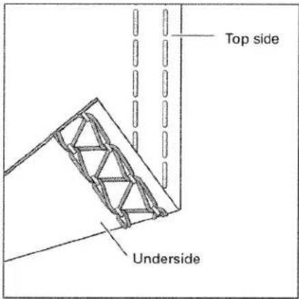
text_image
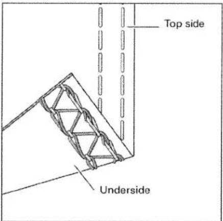
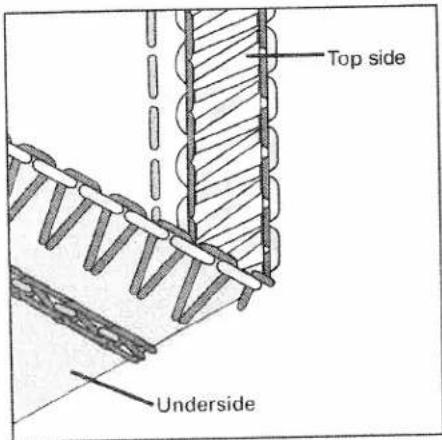
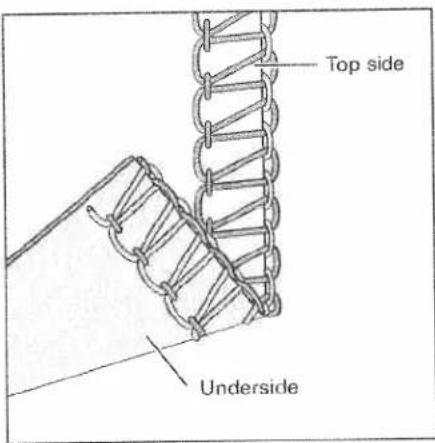
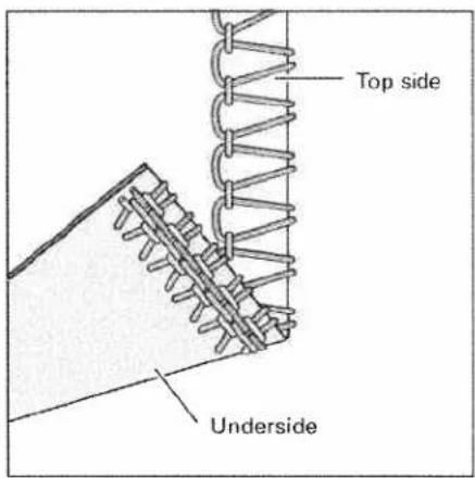
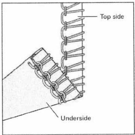
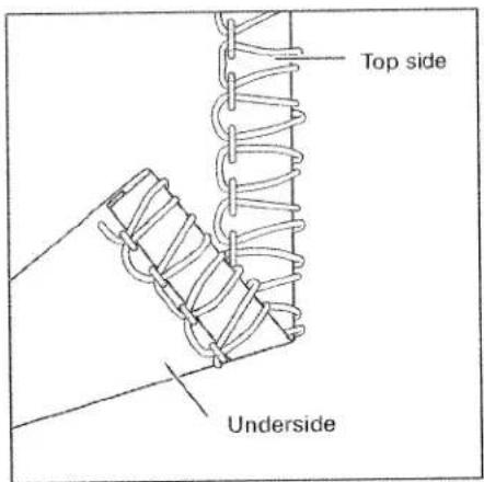
Top side UndersideStitch formation correction measures cover stitch, 2-needle, narrow and wide Program 01, 02
When all tensions are correctly set, the needle threads (green and blue) are just slightly visible on the underside of the fabric. The looper thread (violet) is situated loosely in between.
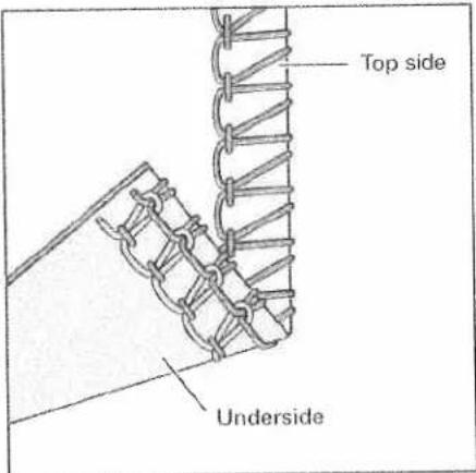
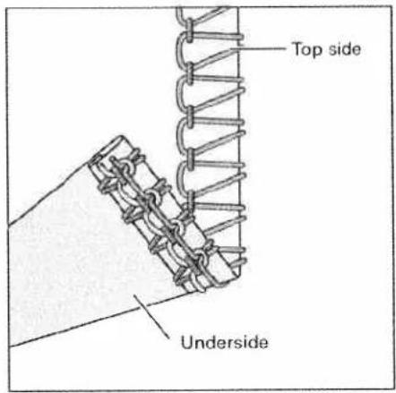
text_image
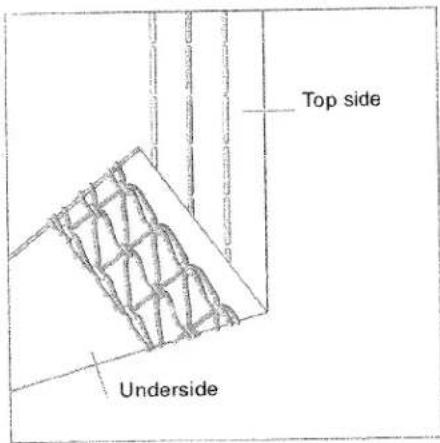
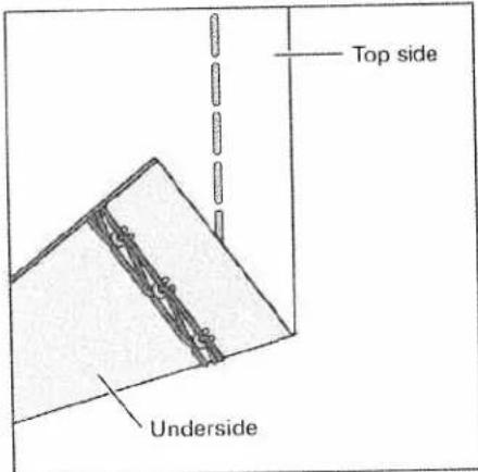
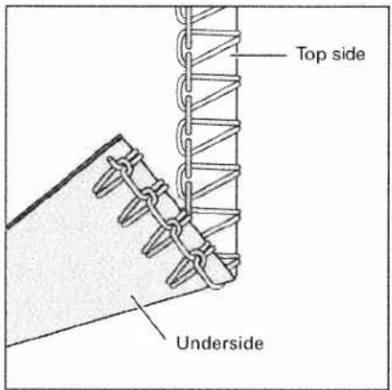
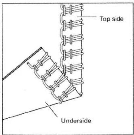
Top side UndersideThe right needle thread (green) is too loose, causing large loops on the underside of the fabric.
Set the green thread tension to a higher value.

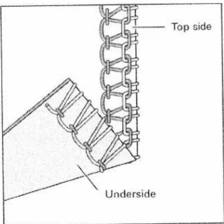
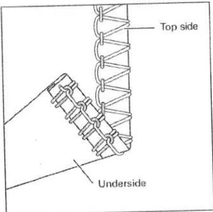
text_image
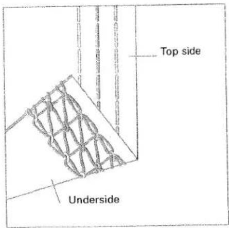
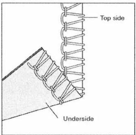
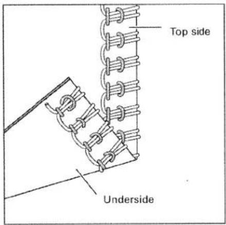
Top side UndersideThe needle threads (green and blue) are set too tightly causing folds in the fabric.
Set the green and blue thread tension to a lower value.
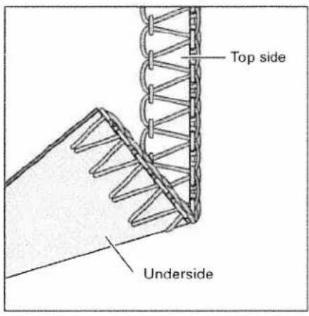
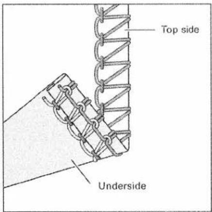
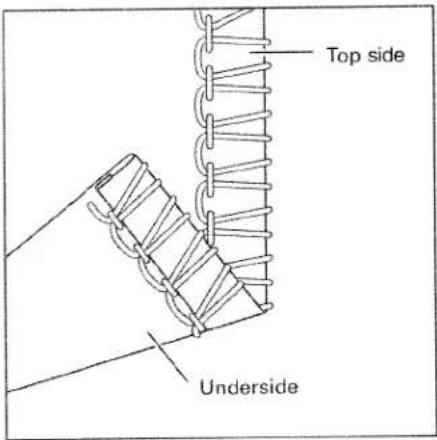
text_image
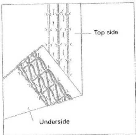
Top side UndersideCover stitch, 3-needle 4-thread
Program 03
When all tensions are correctly set, the needle threads (green, blue and pink) are just slightly visible on the underside of the fabric. The looper thread (violet) is situated loosely in between.
text_image
Top side UndersideThe needle threads (green, blue and pink) are too loose, causing large loops on the underside of the fabric.
Set the green, blue and pink thread tension to a higher value.
text_image
Top side UndersideThe needle threads (green, blue and pink) are set too tightly causing folds in the fabric.
Set the green, blue and pink thread tension to a lower value.
natural_image
Stack of blank white paper sheets on a textured surface (no text or symbols visible)Important notes on sewing with the cover stitch
The power table is marked with various units of measurement. The upper figures are in cm. The lower figures are in inches.
Note: The hemmer guide H2 is available as a special accessory. With this special accessory you can hem your fabric effortlessly without having to press under the hem edge prior to sewing the cover stitch.
natural_image
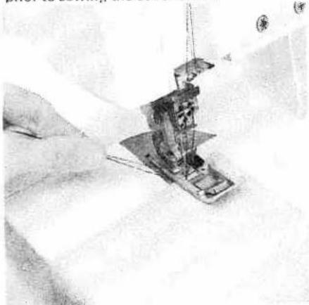
Close-up of hands operating a sewing machine needle on fabric (no visible text or symbols)To start sewing:
Raise the presser foot and place the fabric under the presser foot so the needles pierce the fabric for the first stitch. Position the fabric at the desired width using the marked guidelines on the power table. When starting to sew, pull the fabric taut towards the rear and sew slowly. The speed may be increased as you sew further along the fabric.

natural_image
Close-up of a hand holding a pen and a small object, possibly a tool or device (no visible text or symbols)Preparing the fabric:
When not using the H2 special accessory guide, it is useful to press under the fabric edge before hemming it. The width of fabric to be pressed under must be 0.5 cm wider than the finished hem width. Example: Press under a one inch (2.5 cm) fabric width to sew a finished hem of 3/4 inch (2 cm).
Note: Set the seam width at 3.5 cm.

natural_image
Close-up of a hand using a sewing machine to cut a component (no visible text or symbols)Finishing sewing:
- When sewing to the end of the fabric: Tightly hold the threads at the end of the seam. Sew slowly off the fabric while lightly pulling the threads toward the rear of the machine.
Note: The differential feed may need to be adjusted slightly to allow your fabric to lie, perfectly smooth. Test your settings first on a piece of scrap fabric. 51
natural_image
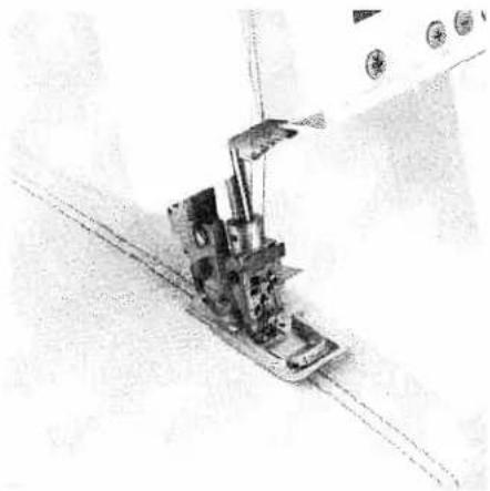
Technical line drawing of a sewing machine needle and fabric (no text or symbols)- If not to sew to the end of the fabric, e.g. sewing tubular fabrics:
Sew 4-5 stitches on top of each other. During the last stitch, turn the hand wheel towards you until the needles pierce the fabric and you have heard each needle "click" (just before the needles are in the lowest position).
natural_image
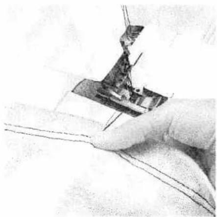
Close-up of a hand using a sewing machine to cut fabric (no visible text or symbols)After the second "click" (if sewing a 2-needle cover stitch) or the third "click" (if sewing a 3-needle cover stitch) turn the handwheel away from you until the needles are in their highest position. Raise the presser foot. Press and hold the Tension Release Key 10. Hold the threads tightly at the end of the seam and pull the fabric from the machine. Cut the threads. Pull the threads through to the back of the fabric and knot them.
natural_image
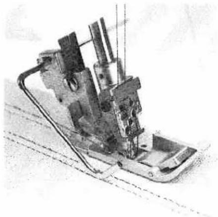
Mechanical sewing machine with needle and base mount (no visible text or symbols)Edge guide
Push the edge guide, from the accessory box, into the guide holder A from the left. The edge guide can be set as required by sliding it to the left or right.
natural_image
Mechanical device with attached components, possibly a sewing machine or industrial machine (no visible text or symbols)The edge guide is useful for serging seams at regular intervals with the cover stitch or two thread chainstitch.

text_image
Top side Underside5-thread safety-stitch seam
Program 20
Since the 5-thread safety-stitch seam consists of the 2-thread chainstitch and the 3-thread overedge seam, you can refer to the correction possibilities of these seams below and on page 55.
text_image
Top side Underside4-thread safety-stitch seam
Program 19
Since the 4-thread safety-stitch seam consists of the 2-thread chainstitch and the 2-thread flatlock, you can refer to the correction possibilities of these seams below and on page 57.
Note: Attach the converter (see page 33), when sewing a 4-thread safety-stitch seam.

text_image
Top side Underside2-thread chainstitch
Program 04
When all tensions are correctly set, the needle thread (blue) is just slightly visible on the underside of the fabric.
text_image
Top side UndersideThe needle thread (blue) is too loose, causing larger needle thread loops on the underside of the fabric.
Set the blue thread tension to a higher value.

text_image
Top side Underside4-thread overedge seam
Program 18
When all tensions are correctly set, the loops of both looper thread (pink and yellow) are directly on the edge of the fabric.

text_image
Top side UndersideThe needle threads (blue and green) are too loose, causing larger loops of needle thread on the underside of the fabric.
Set the blue and green thread tension to a higher value.

text_image
Top side UndersideThe upper looper thread (pink) appears on the underside of the fabric.
Set the pink thread tension to a higher value and/or the yellow thread tension to a lower value.

text_image
Top side UndersideThe lower looper thread (yellow) appears on the top side of the fabric.
Set the yellow thread tension to a higher value and/or the pink thread tension to a lower value.
text_image
Top side Underside3-thread overedge seam
narrow and wide
Program 10 and 11
When all tensions are correctly set, the loops of both looper threads (pink and yellow) are directly on the edge of the fabric.

text_image
Top side UndersideThe needle thread is too loose, causing loops on the underside of the fabric.
Set the relevant needle thread tension to a higher value.
text_image
Top side UndersideThe upper looper thread (pink) appears on the underside of the fabric.
Set the pink thread tension to a higher value and/or the yellow thread tension to a lower value.
text_image
Top side UndersideThe lower looper thread (yellow) appears on the top side of the fabric.
Set the yellow thread tension to a higher value and/or the pink thread tension to a lower value.
text_image
Top side Underside3-thread flatlock
narrow and wide
Program 13 and 14

text_image
Top side UndersideThe needle thread is too tight.
Set the needle thread tension (blue) to a lower value.
text_image
Top side UndersideThe upper looper thread (pink) appears on the underside of the fabric.
Set the pink thread tension to a higher value.

text_image
Top side UndersideThe lower looper thread (yellow) is too loose.
Set the yellow thread tension to a higher value.
text_image
Top side Underside2-thread flatlock
narrow and wide
Program 05 and 06
When all tensions are correctly set, the loops of both threads are directly on the underside of the fabric.
Note: If you want to sew the 2-thread flat-lock seam, then you will need to attach the converter (see page 33).

text_image
Top side UndersideThe needle thread is too loose or the lower looper thread (yellow) is too tight.
Set the relevant needle thread tension to a higher value and/or the yellow thread tension to a lower value.
text_image
Top side UndersideThe lower looper thread (yellow) is too loose and/or the needle thread is too tight.
Set the yellow thread tension to a higher value and/or the relevant needle thread tension to a lower value.

text_image
Top side Underside3-thread flat hem Program 16

text_image
Top side UndersideThe right needle thread (green) is too loose. Set the green thread tension to a higher value.
text_image
Top side UndersideThe upper looper thread (pink) appears on the underside of the fabric.

text_image
Top side UndersideThe lower looper thread (yellow) appears on the top side of the fabric.
Set the pink thread tension to a higher value and/or the yellow thread tension to a lower value.
Set the yellow thread tension to a higher value and/or the pink thread tension to a lower value.
text_image
Top side Underside3-thread rolled hem (folded) Program 17

text_image
Top side UndersideThe right needle thread (green) is too loose. Set the green thread tension to a higher value.
text_image
Top side UndersideThe upper looper thread (pink) only partly loops around the fabric edge.

text_image
Top side UndersideThe lower looper thread (yellow) appears on the top side of the fabric.
Set the pink thread tension to a lower value and/or the yellow thread tension to a higher value.
Set the yellow thread tension to a higher value and/or the pink one to a lower value.

text_image
Top side Underside2-thread flat hem
Program 08
Note: If you want to sew the 2-thread flat hem, then you will need to attach the converter (see page 33).
text_image
Top side UndersideThe right needle thread (green) is too loose.
Set the green thread tension to a higher value and/or the yellow thread tension to a lower value.

text_image
Top side UndersideThe lower looper thread (yellow) is too loose.
Set the yellow thread tension to a higher value.
text_image
Top side Underside2-thread rolled hem (folded)
Program 09
Note: If you want to sew the 2-thread rolled hem, then you will need to attach the converter (see page 33).

text_image
Top side UndersideThe right needle thread (green) is too loose.
Set the green thread tension to a higher value and/or the yellow thread tension to a lower value.
text_image
Top side UndersideThe lower looper thread (yellow) is too loose.
Set the yellow thread tension too a higher value.
text_image
Top side Underside2-needle 3-thread overedge seam
Program 15
Note: If you want to sew the 2-needle 3-thread overedge seam, then you will need to attach the converter (see page 33).

text_image
Top side UndersideThe left needle thread (blue) is too loose.
Set the blue thread tension to a higher value.
text_image
Top side UndersideThe right needle thread (green) is too loose.
Set the green thread tension to a higher value.

text_image
Top side UndersideThe lower looper thread (yellow) is too tight.
Set the yellow thread tension to a lower value.
| Thread chart for 2-, 3- and 4-thread overedge seams | ||
| Fabric | Thread | Stitch length |
| Light fabrics:organdy, fine knitwear,taffeta, silk, lining fabrics | Cotton no. 50 - 70Synthetic thread no. 70 - 140 | 2.0 - 4.0 mm |
| Medium-heavy fabrics:cotton, tricot, linen,dress fabrics | Cotton no. 40 - 60Synthetic thread no. 70 - 140 | 2.0 - 4.0 mm |
| Heavy fabrics:tweed, suit fabrics,denim, heavy cloth | Cotton no. 30 - 50Synthetic thread no. 70 - 140 | 2.0 - 4.0 mm |
| Knitwear: | Cotton no. 40 - 60Synthetic thread no. 70 - 140 | 2.0 - 4.0 mm |
| 2 or 3-thread rolled hems | Polyester thread no. 120 - 140Mercerized thread (bulk thread) | 1.0 - 2.0 mm |

natural_image
Close-up of a mechanical device with internal components and a person in safety gear (no visible text or symbols)Removing the needle plate
Raise the presser foot and move the needle(s) to the highest position. Remove the presser foot and open the swivel plate. Press down the needle plate disengaging lever 33. The needle plate 18 is raised out of its mount. The needle plate can be removed to the left.
Note:
The machine should be unthreaded when removing the needle plate.
natural_image
Black-and-white photo of a person operating a large mechanical device, possibly a robotic or industrial machine (no visible text or symbols)Inserting the needle plate
Place the needle plate to the rear on the guide pin (A) and press down at the front until you hear it click into place.
natural_image
Interior view of a sewing machine with visible mechanical components and control panel (no text or symbols)Machine maintenance
Cleaning the machine
Switch off the electrical power
Remove the trimming waste box and open the looper cover and swivel plate. Disengage the upper blade (see page 31) and remove the presser foot and the needle plate.
Use the accessory brush provided to remove any waste thread from the upper and lower blades, the differential feed and the looper area.
natural_image
Mechanical assembly diagram showing internal components and parts (no visible text or labels)
natural_image
Close-up of a hand holding a small object, possibly cleaning or cleaning a surface (no visible text or symbols)Lubricating the machine
Switch off the electrical power
Move the upper overedge looper into its highest position. Lubricate the points shown above with the oil provided (located in the accessory box) every time you clean the machine. One or two drops of PFAFF sewing machine oil are sufficient. All other parts are manufactured from special materials and do not require any lubrication.
Cleaning the rubber feet
Clean the rubber feet from time to time with alcohol. This ensures good stability.

natural_image
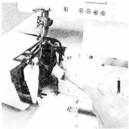
Close-up of a hand using a tool to adjust or install electronic components (no visible text or symbols)Changing the upper blade
Switch off the electrical power
To remove: Set the adjusting knob for seam width to 3.5 mm. Fasten the upper blade (see page 35) before loosening the fastening screw A with the wrench provided in the accessory box. Then remove the upper blade.
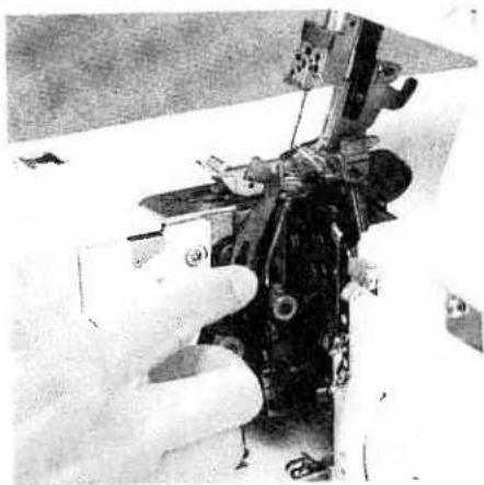
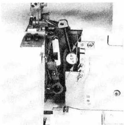
natural_image
Close-up of a hand operating a sewing machine with visible wiring and components (no text or symbols)To insert: Attach the new upper blade and gently tighten the fastening screw. Then turn the handwheel until the upper blade is in the lowest position.
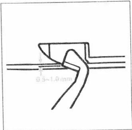
text_image
0.5~1.0mmIn this position the front edge of the upper blade must be 0.5 to 1.0 mm lower than the cutting edge of the lower blade. When the upper blade has been properly inserted you can fully tighten the fastening screw. Loosen the screw to the movable upper blade.
natural_image
Interior view of a kitchen appliance with a showerhead and a bowl (no visible text or symbols)Changing the light bulb
Switch off the electrical power
Using the screw driver in the accessory box loosen the fastening screw to the sewing light cover 23 until this can be removed.

natural_image
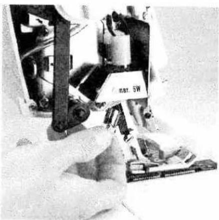
Person operating a mechanical device with a circular component and a triangular base (no visible text or symbols)Push the light bulb fully into its socket, during which pin A moves upward. Rotate counterclockwise through half a turn and remove.
natural_image
Close-up of hands operating a mechanical device with a labeled component (no visible text or symbols)Guide the new light bulb (max. 5 W) into the socket and twist until both pins on the bulb click into place. Press the bulb right into the socket, twisting it clockwise until it is securely fixed.
Replace the sewing light cover and tighten the fastening screw.
Special Accessories
This machine offers a wide range of special accessories for special serging details. Consult your PFAFF dealer.
| Special accessory | Order No. | Use |
| Multi-purpose foot M | 29 924 993 82-002 | Foot, to which guides H1, H2 and H3 can be attached |
| Lace and braiding guide H1 | 29 924 993 82-003 | Guide for applying lace or braiding (to the under side of the fabric) |
| Hemmer guide H2 | 29 924 993 82-001 | Guide for hemming/turns under one inch while serging |
| Bias-tape guide H3 | 29 924 993 82-004 | Guide for applying bias tape as edging |
| Clear foot N | 29 924 993 82-006 | Presser foot with groove It can be used together with guide N1 |
| Faggoting guide F2 | 29 924 993 82-008 | Guide for joining two pieces of fabric with consistent clearance. Use transparent presser foot F from the accessory box |
| Lace guide F3 | 29 924 993 82-005 | Guide for applying lace (on the upper side of the fabric). Use transparent presser foot F from the accessory box |
| Flat-felled-seam guide F4 | 29 924 993 82-009 | Guide for sewing flat-felled seams Use transparent presser foot F from the accessory box |
| Fancy-stitch guide N1 | 29 924 993 82-007 | For stitching down a double chainstitch or a 3-thread overedge seam and for decorative effects |
| Cording foot K | 9 924 993 82-011 | For serging cording with the cording tongue K1 and the guide K2 |
| Cording tongue K1 | 29 924 993 82-012 | For serging pintucks |
| Cording guide K2 | 29 924 993 010 | For serging cording with gimp thread |
| Strap and belt-loop foot L | 29 924 993 82-013 | For sewing belt loops and straps, and for ornamental stitches with a cover stitch |
| Universal tape binder | 29 924 993 82-014 | For binding fabric edges with various widths of pre-made bias tape |
| Beading foot P | 29 924 993 82-015 | For serging on beading and sequins |
| Bead needle plate P | 29 924 993 82-016 | The bead needle plate P together with the beading foot P allows you to serge on beading and make a rolled hem simultaneously. |
| Multi-purpose foot C | 29 924 993 82-017 | For sewing on bands, elastic tape, elastic thread and fishing line together with the various elastic tape inserts |
| Elastic tape insert 7.5 mm | 29 924 993 82-034 | For sewing on elastic tape with a width up to 7.5 mm |
| Elastic tape insert 10 mm | 29 924 993 82-035 | For sewing on elastic tape with a width from 7.5 mm - 10 mm |
| Elastic tape insert 13 mm | 29 924 993 82-036 | For sewing on elastic tape with a width from 10 mm - 13 mm |
| Shirring/Gathering foot G | 29 924 993 82-018 | For shirring/gathering and joining two pieces of fabric simultaneously |
| Blindstitch foot D | 29 924 993 82-019 | For serging blind hems and ornamental seams |
| Band and braiding foot Q | 29 924 993 82-020 | For sewing on bands and braiding. Gimp cords and thread and bands with decorative threads can be stitched over using this foot together with guide K2 |
| Accessory holder | 29 924 993 82-021 | Holder, to which the following accessories together with the retaining screw and the swiveling arm can be attached. |
| Retaining screw | 29 924 993 82-023 | For securing the following accessories to the accessory holder |
| Edge guide with units of measurement | 29 924 993 82-022 | For guiding the fabric edge and measuring cut widths and seam widths simultaneously (use the machine's standard presser foot) |
| Gathering/ Shirring tongue | 29 924 993 82-027 | For gathering/shirring and joining two pieces of fabric simultaneously (use the machine's standard presser foot). |
| Tape binder 40 mm | 29 924 993 82-031 | For binding the fabric edge with 40 mm tape. Binding width 10 - 12 mm. (Use the machine's standard presser foot.) |
| Swiveling arm | 29 924 993 82-024 | For attaching the following accessories to the accessory holder |
| Curved-seam guide | 29 924 993 82-025 | For serging a curved piece to a straight piece of fabric (use the machine's standard presser foot). |
| Piping and welting foot E | 29 924 993 82-028 | Presser foot for guiding and sewing in piping and welting |
| Piping and welting accessory | 29 924 993 82-030 | Together with piping foot E, for binding and guiding piping and gimp between two layers of fabric |
Sewing problems and their solutions
This machine has been developed with ease of operation in mind. No difficult or tricky settings need to be made. Sewing problems of the kind described below may occur as a result of minor adjustment and operating errors. They can be easily adjusted by following the instructions.
| Problem | Cause | Solution |
| Needle breakage | The needle was bent or the point damaged. | Insert new needle.(see page 13) |
| The needle was not fully inserted. | Insert needle fully(see page 13). | |
| The fabric was pulled too firmly. | Do not pull on the fabric when sewing. | |
| Thread breaks | Incorrectly threaded. | Thread properly(see page 14 - 23). |
| Thread has caught. | Check if the thread is caught on the spool stand etc | |
| Thread tension is too tight. | Correct the tension(see page 49 – 62). | |
| Needle not fully inserted. | Insert needle correctly(see page 13). | |
| Incorrect needle used. | Use needle systemEL X 705. | |
| Skipping stitches | Needle bent or point damaged. | Insert new needle(see page 13). |
| Needle not fully inserted. | Insert needle correctly(see page 13). | |
| Incorrect needle used. | Use needle systemEL X 705. | |
| Incorrectly threaded. | Thread correctly(see page 14 - 23). | |
| Stitch formation faulty | Incorrect setting of thread tensions | Re-set thread tensions(see page 49 – 62). |
| 3 or 4 thread overedge seam has an irregular appearance and the upper looper thread has not interlocked in the seam. | The converter is attached. | The converter must be removed (see page 33). |
| Machine will not operate although master switch is on. | Power supply interrupted | Close looper cover (see page 8) |
| Fabric not neatly trimmed | Waste thread between upper and lower bladeUpper blade is blunt. | Clean blades.Replace upper blade (see page 66). |
| Puckered seams | Thread tension too tight.Incorrect setting of differential feed.Thread has caught due to incorrect threading. | Reduce thread tensionRe-adjust differential feed (see pages 38, 39)Thread correctly (see pages 14 - 23). |
| Fabric not fed through evenly | Stitches too shortSewing foot pressure too low for heavy fabrics.Sewing foot pressure too high for lightweight fabrics. | Increase stitch length see page 35)Increase sewing foot pressure (see page 29).Reduce sewing foot pressure (see page 29). |
Specifications
| Maximum sewing speed | 1500 stitches/min. |
| Seam width | 1.4 mm - 9.0 mm |
| Cover stitch width | 2.5 mm, 5 mm |
| Stitch length | 0.5 mm - 4 mm |
| Presser foot | exchangeable |
| Lubrication | manual |
| Presser foot height | 4.5 mm |
| Overedge stroke | 2.0 mm |
| Needle system | EL X 705, cat no. 2002 |
| Needle size | 80/12, 90/14 |
| Number of threads | 2, 3, 4, 5 |
| Dimensions (width x height x depth) | 355 x 290 x 300 mm |
| Weight | 10 kg |
Packing contents
| 1 machine |
| 1 foot control |
| 1 instruction manual/guarantee card |
| 1 waste container |
| 1 machine cover |
| 1 accessory box |
| 1 power table |
Parts of the coverlock 4872
38 Thread guides with color coding
39 Telescoping thread guide
40 Thread chain cutter
41 Thread spool stand
42 Thread spool pin
43 Cone thread adapter
44 Spool disc
45 Machine socket, power cord
46 Electrical power master switch
47 Machine socket, foot control
48 Handwheel
49 Regulator wheel for differential feed
50 Stitch length adjustment knob
51 Presser foot lifter
52 Rear thread guides
53 Waste container
54 Foot control
55 Power cord
56 Accessory box
57 Power table
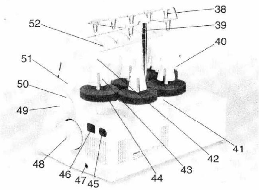
text_image
38 39 40 52 51 50 49 48 46 47 45 44 43 42 41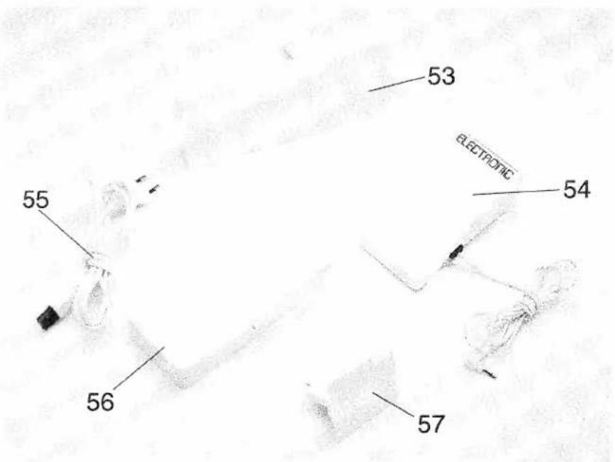
text_image
53 ELECTRONIC 54 55 56 57G. M. Pfaff
Aktiengesellschaft
Information subject to change without notice.
No.: 29-629 989-54/000
Englisch · 11/98