coverstyle 4850 - Sewing machine PFAFF - Free user manual and instructions
Find the device manual for free coverstyle 4850 PFAFF in PDF.

User questions about coverstyle 4850 PFAFF
0 question about this device. Answer the ones you know or ask your own.
Ask a new question about this device
Download the instructions for your Sewing machine in PDF format for free! Find your manual coverstyle 4850 - PFAFF and take your electronic device back in hand. On this page are published all the documents necessary for the use of your device. coverstyle 4850 by PFAFF.
USER MANUAL coverstyle 4850 PFAFF
text_image
4850 cover/style Owner's manual
text_image
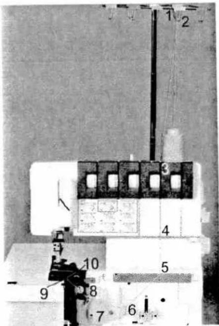
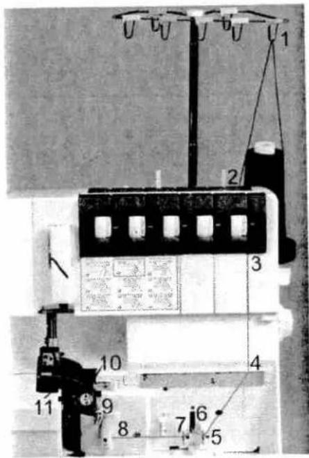
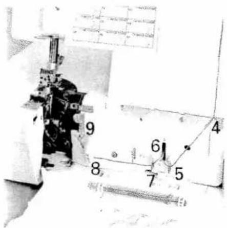
Labeled diagram of a sewing machine with numbered parts for identification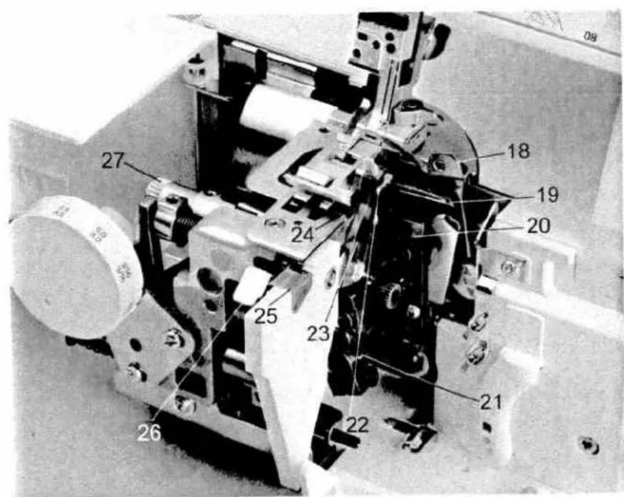
text_image
27 18 19 20 24 25 23 21 22 26Parts of the coverstyle
1 Upper needle-thread tension
2 Upper needle-thread tension
3 Carry handle
4 Thread tension/upper looper thread
5 Thread tension/lower looper thread
6 Thread tension/two-thread chainstitch looper/cover stitch looper
7 Looper cover
8 Blade guard
9 Looper disengaging lever
10 Standard presser foot
11 Needle plate
12 Swivel plate
13 Adjusting knob for seam width
14 Seam width viewing window
15 Needle holder
16 Sewing light cover
17 Adjusting knob for presser foot pressure
18 Upper overedge looper
19 Lower overedge looper
20 Two-thread chainstitch looper
21 Threading aid for the two-thread chainstitch looper/cover stitch looper
22 Swiveling stitch width latch
23 Movable upper blade
24 Fixed lower blade
25 Clamp spring for serging thread chains
26 Needle plate disengaging lever
27 Handwheel for lowering the upper blade
This household sewing machine is designed to comply with IEC/EN 60335-2-28 and UL1594
IMPORTANT SAFETY INSTRUCTIONS
When using an electrical appliance, basic safety precautions should always be followed, including the following:
Read all instructions before using this household sewing machine.
DANGER - To reduce the risk of electric shock:
- A sewing machine should never be left unattended when plugged in. Always unplug this sewing machine from the electric outlet immediately after using and before cleaning.
• Always unplug before relamping. Replace bulb with same type rated 15 Watt.
WARNING - To reduce the risk of burns, fire, electric shock, or injury to persons:
- Do not allow to be used as a toy. Close attention is necessary when this sewing machine is used by or near children and infirm persons.
• Use this sewing machine only for its intended use as described in this manual. Use only attachments recommended by the manufacturer as contained in this manual. - Never operate this sewing machine if it has a damaged cord or plug, if it is not working properly, if it has been dropped or damaged, or dropped into water. Return the sewing machine to the nearest authorized dealer or service center for examination, repair, electrical or mechanical adjustment.
- Never operate the sewing machine with any air openings blocked. Keep ventilation openings of the sewing machine and foot controller free from the accumulation of lint, dust, and loose cloth.
- Keep fingers away from all moving parts. Special care is required around the sewing machine needle and blades.
• Always use the proper needle plate. The wrong plate can cause the needle to break. - Do not use bent needles.
- Do not pull or push fabric while stitching. It may deflect the needle causing it to break.
- Switch the sewing machine off ("0") when making any adjustment in the needle area, such as threading needle, changing needle, threading bobbin, or changing presser foot, etc.
- Always unplug sewing machine from the electrical outlet when removing covers, lubricating, or when making any other user servicing adjustments mentioned in the instruction manual.
• Never drop or insert any object into any opening.
• Do not use outdoors. - Do not operate where aerosol (spray) products are being used or where oxygen is being administrated.
- To disconnect, turn all controls to the off ("0") position, then remove plug from outlet.
- Do not unplug by pulling on cord. To unplug, grasp the plug, not the cord.
- "CAUTION: MOVING PARTS - TO REDUCE RISK OF INJURY, SWITCH OFF BEFORE SERVICING. REPLACE COVER." located on the inside of Looper Cover and Swivel Plate.
SAVE THESE INSTRUCTIONS
[Non-Text]
[Non-Text]
[Non-Text]
[Non-Text]
[Non-Text]
[Non-Text]
[Non-Text]
[Non-Text]
[Non-Text]
[Non-Text]
[Non-Text]
[Non-Text]
text_image
PFAFFSimple, up-to-date sewing
Congratulations! You have bought a high-quality product that provides unique advantages. Your new coverstyle can take any material in its stride and will sew through thick and thin for you.
Your PFAFF coverlock features the very latest in design and technology, and it is just as simple to operate as this instruction manual is to follow.
Before you start sewing, please take the time to read these instructions carefully. It is certainly time well spent, and is the best way to find out just what your machine can do and make full use of all its features.
If you have any further questions, just ask your authorized PFAFF dealer. Your dealer is happy to be of service with any help or advice.
Let's get started! We wish you many enjoyable hours creating your very own fashions and projects!
Contents
Accessories 6
Accessories, optional 62, 63
Accessory box....6
Adjusting the machine to Prog. 01, 02 34, 35
Changing a spool on a threaded machine. 24
Clamp spring 29
Cleaning the machine 58
Cone thread adapter. 10
Converter, attaching 32
Cover stitch, important notes on sewing. 44, 45
Differential feed 36, 37
Edge guide 45
Electrical connection
Electrical power master switch
Foot control, connecting
Light bulb (sewing lamp), changing 60
Looper cover 8
Lubricating the machine 58
Machine cover 6
Maintenance....58-60
Needle holder....13
Needle inserting tool 13
Needle plate disengaging lever....38
Needle plate, removing 38
Needle position 12
Needle threader 25
Needle, changing....13
Power table. 35
Presser foot lifter 10
Presser foot pressure....28
Presser foot 1
Presser foot, changing.
Program overview 40-43
Rubber feet, cleaning.
Safety instructions....1,2
Seam width adjusting knob....3
Seam width viewing window.
Seam width, setting 3
Sewing light cover 60
Contents
Page
Sewing problems and their solutions 61
Specifications....64
Spool disc 10
Spool holder....9
Stitch formation correction measures....46-56
Stitch length adjustment knob....38
Stitch length, adjusting 38
Stitch width latch, swiveling 31
Telescoping thread guide 9
Thread chain cutter 29
Thread chart....57
Thread guide, clip-on....10
Thread net 9
Thread tensions, setting 39
Thread unreeling disc 9
Threading aid for the 2-thread chainstitch looper/cover stitch looper ..... 19, 21
Threading paths/overview 26-28
Threading the 2-thread chainstitch looper/cover stitch looper (violet)....18-21
Threading the lower overedge looper (yellow)....16, 17
Threading the needle(s)....22, 23
Threading the upper overedge looper (pink)....15
Threading, important note. 24
Threading/Thread guides....14
Upper blade, changing 59
Upper blade, disengaging 30
Upper blade, securing 39
Waste container 8
text_image
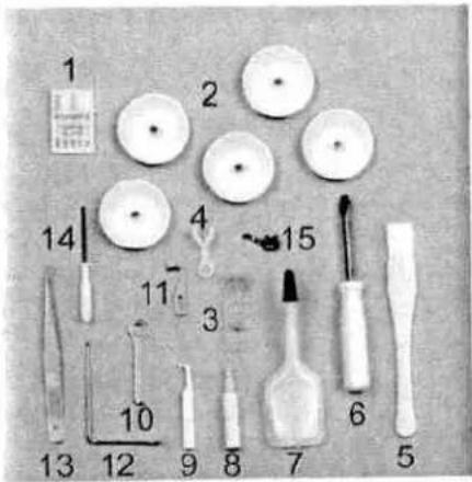
Labeled diagram of a mechanical or dental tool set with numbered components for identification.Accessory box
Open the accessory box 47 by gently pressing the bottom of the box inwards. The following accessories can be found in the box:
1 Overlock needle system EL X 705. cat. no. 2002
2 Thread unreeling discs (5)
3 Transparent presser foot (F) for cover stitch and two-thread chainstitch
4 Clip-on thread guide
5 Cleaning brush
6 Screw driver
7 Machine oil
8 Needle threader
9 Needle inserting tool
10 Wrench
11 Replacement upper blade
12 Edge guide
13 Tweezers
14 Allen key
15 Converter
text_image
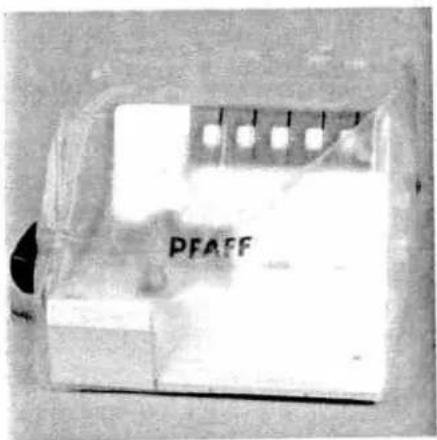
PFAFFMachine cover
The machine cover protects the machine from dust and dirt. When the sewing process is finished, push the telescopic thread guide 32 together. The spool stand 34 must be pushed to its full extent in to the machine, regardless of whether a spool is attached. Place the cover over the machine. The accessories should be stored in the accessory box.
natural_image
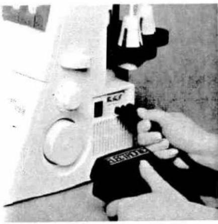
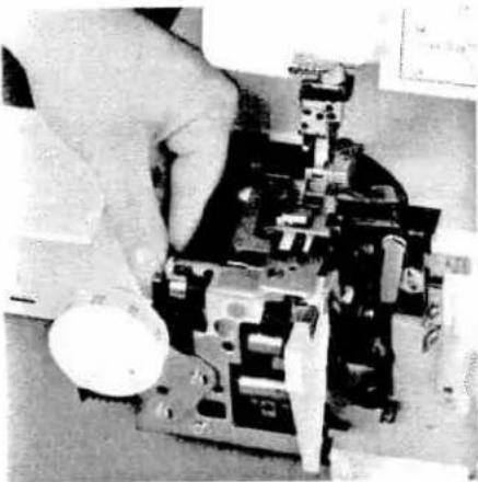
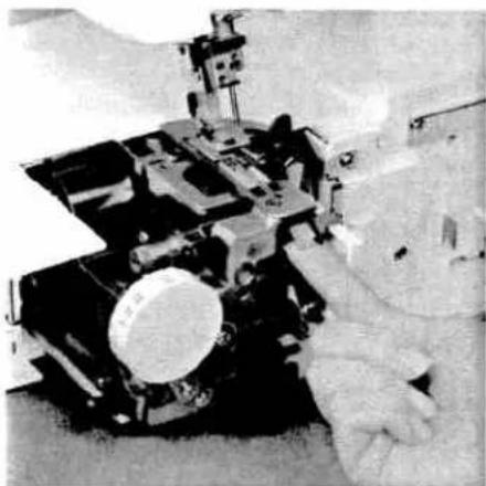
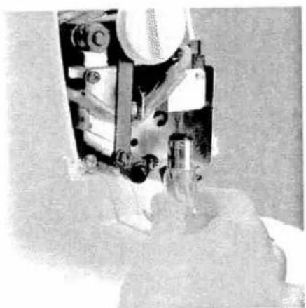
Close-up of a hand operating a small electronic device with a label 'SARATO' visible (no readable text or symbols on the device itself)Connecting the foot control
Connect the plug of the foot control to the connection socket 39 of the machine. The sewing speed is regulated by activating the foot control.
text_image
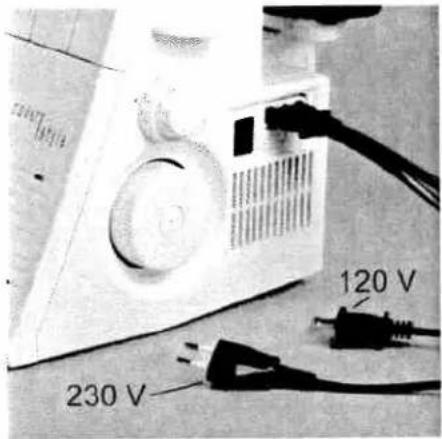
120 V 230 VElectrical connection
Connect the foot control cord with the wall outlet.

natural_image
Close-up of a mechanical device with circular components and a black cable inserted (no visible text or symbols)Master switch
When you turn on the master switch 38 the sewing lamp is illuminated. The machine is now operational.
For USA and Canada
This appliance has a polarized plug (one blade wider than the other).
To reduce the risk of electric shock, it is designed to fit into a polarized outlet only one way. If the plug does not fit correctly into the outlet, reverse the plug. If it still does not fit, contact a qualified electrician to install the proper outlet.
Do not modify the plug in any way.
Foot controller type 4C-325G - 230V / 4C-335B - 110-125V / 4C-335G - 220-240V has to be used with this overlock machine.

text_image
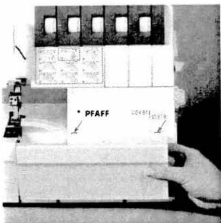
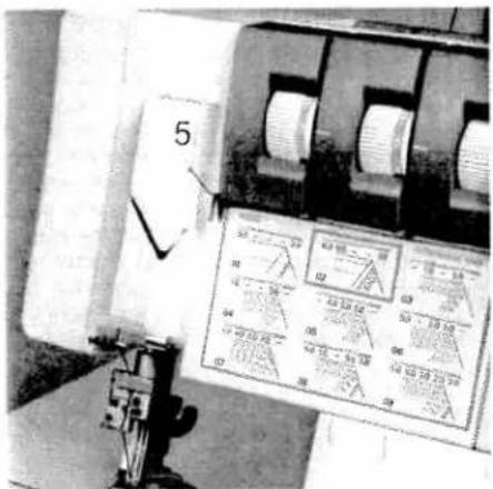
PFAFFLooper cover
Push the looper cover 7 fully to the right and then swivel it down. Five types of stitches and their threading paths are portrayed in color on the inside of the looper cover.
Note: The electricity supply of the machine is cut off as soon as the looper cover or swivel plate 12 is opened, for safety reasons, i.e. sewing with the machine is no longer possible.
text_image
PFAFF 20V 40V 15V 30V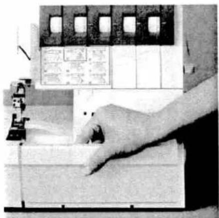
natural_image
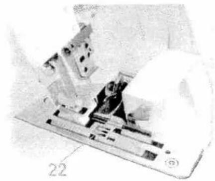
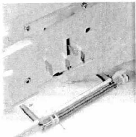
Close-up of a hand operating a sewing machine with a computer monitor and control panel visible (no text or symbols)Waste container (optional,
Order No 2992499381111)
Insert the upper latch of the waste container 45 into the upper slot of the looper cover 7.
To remove the waste container, repeat this procedure in the reverse order.
Apply pressure to the lower part of the container until the lower latches click into place in the lower slots of the looper cover.
natural_image
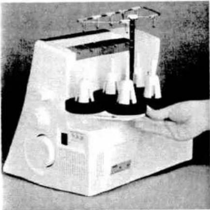
Hand operating a laboratory instrument with test tubes and a paper holder (no visible text or labels)Spool holder
Before placing thread cones/spools on machine you must pull the spool holder 34 fully away from the back of machine.
natural_image
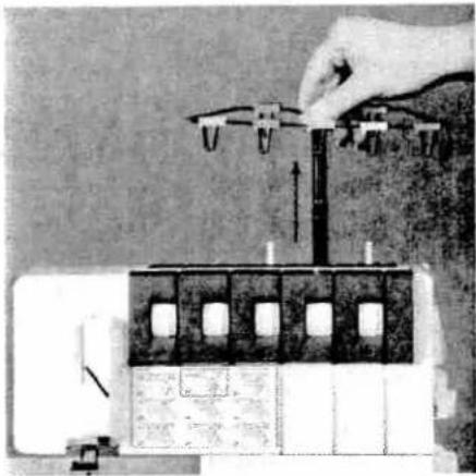
Illustration of a hand using a tool to adjust or install a mechanical component (no text or symbols visible)Telescopic thread guide
Pull the telescopic thread guide 32 upwards to its highest position.
To ensure optimum thread feed, turn the telescopic parts slowly until you hear the locking balls click into place.
natural_image
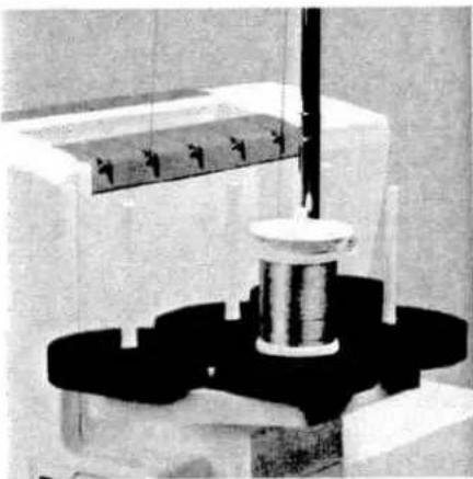
Close-up of a mechanical testing setup with a central rotating component and a rectangular block (no visible text or symbols)Thread unreeeling disc
The thread unreeling disc (in the accessory box) is used for small spools/spools with notched or rough ends. Place the spool on the spool pin 35. Place the thread unreeling disc on top of the spool. Make sure the spool disc 37 is used under the spool.

natural_image
Hand operating a mechanical testing machine with a cylindrical component on top (no visible text or symbols)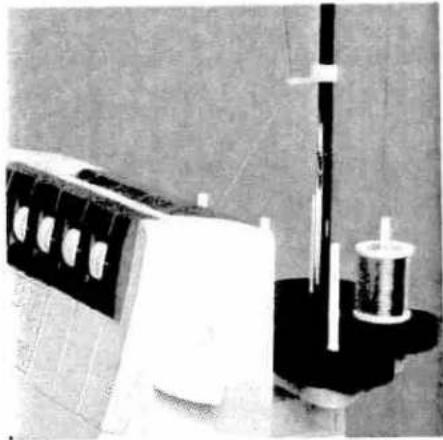
natural_image
Black-and-white photo of a portable radio with a stand and cylindrical device (no visible text or symbols)Spool disc/cone thread adapter
It is advantageous to use the spool disc 37 when sewing with large spools (5,000 - 10,000 m). To do this, place the cone thread adapter 36 onto the spool pin 35. With synthetic threads, the spool discs help eliminate vibration of the cones/spools aiding in smoother feeding of the threads.
Clip-on thread guide
Use the clip-on thread guide accessory when sewing with decorative thread. Clip this onto the telescoping thread guide 32 and thread the machine as shown in the illustration. Use the thread net and/or the thread unreeling disc if needed.

text_image
Black-and-white photo of a hand operating a PFAFF radio device with visible control panel and text labels
natural_image
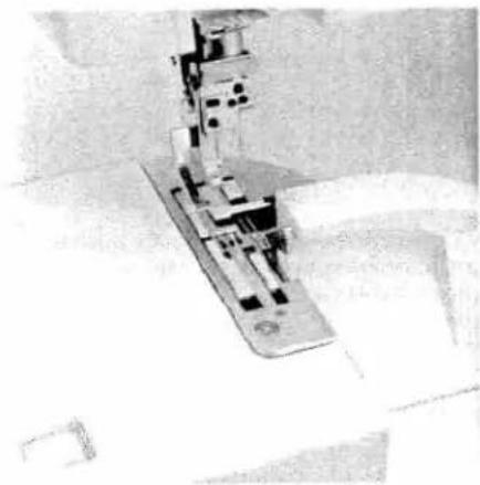
Close-up of hands operating a sewing machine with fabric (no visible text or symbols)Presser foot lifter
The presser foot can be raised and lowered using the presser foot lifter 43. The maximum vertical lift of 6.5 mm for the presser foot for particularly thick fabrics can be achieved by pressing the presser foot lifter towards the rear.
Once an initial thread chain has been created, the presser foot lifter no longer needs to be raised if you continue working with the same thread and presser foot. It is sufficient to gently lift the front part of the presser foot using your thumb. Slide the fabric under the raised part of the presser foot. The fabric is automatically taken up and fed into the machine when you activate the foot control.

natural_image
Two mechanical components with no visible text or symbolsPresser foot
With standard presser foot 10 use setting "A" on the spring-loaded presser foot latch for the cover stitch (Prog. 02), the 2-thread chainstitch (Prog. 01), the 5-thread safety-stitch seam (Prog. 09) and the 4-thread safety-stitch seam (Prog. 08).
Transparent presser foot F from the accessories can also be used for the cover stitch (Prog. 02).
For all other programs use standard presser foot 10 and setting "B" on the spring-loaded presser foot latch.

natural_image
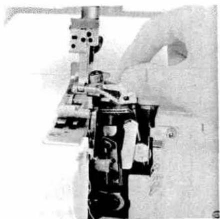
Close-up of a sewing machine needle stitching fabric, no visible text or symbolsChanging the presser foot
Switch off the electrical power
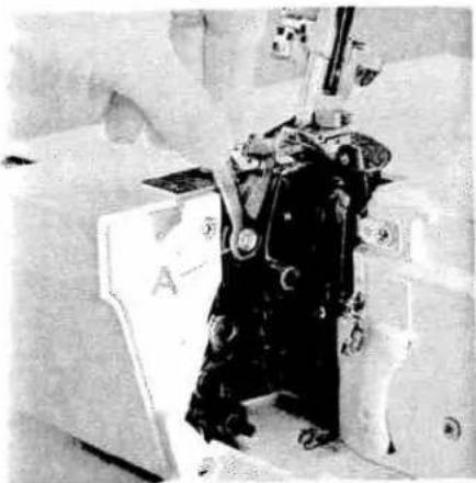
To remove: Raise the needle(s) to the highest position by turning the handwheel towards you. Raise the presser foot and press lever A at the rear of the presser foot holder. The presser foot will be released automatically from the holder. Pivot the presser foot clockwise until the front half of presser foot clears holder and remove by sliding foot away from you towards back of machine.
natural_image
Mechanical assembly diagram showing layered components and mounting brackets (no visible text or labels)To attach: Place the presser foot behind and perpendicular to the presser foot holder. Pivot the presser foot counterclockwise until the pin of the foot is directly under the presser foot holder clamp. Lower the presser foot lever and press lever A, if necessary, until the foot then clicks into place.
Check: Please lift the presser foot lever to ensure that the presser foot is properly locked into place.
text_image
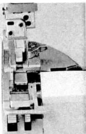
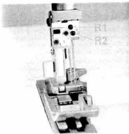
R1 R2Needle position
This machine has 4 needle positions and can sew with a maximum of two needles at any one time. The needle positions are L1, L2, R1 and R2. The fastening screw is located directly above the corresponding needle.
text_image
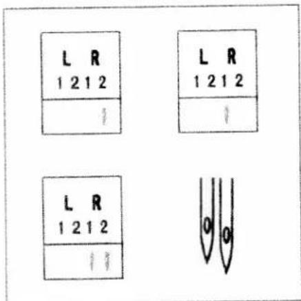
L R 1 2 1 2 L R 1 2 1 2 L R 1 2 1 2 0 0The different needle positions are depicted in a schematic drawing in the instruction manual. Also refer to the examples above and below. Insert the needle(s) as shown on the program overview (see pages 40-43).
Note: If the needles R2 and R1 have been inserted, the left needle will be somewhat higher than the right needle.

text_image
L2 L1Note: If the needles L1 and L2 have been inserted, the left needle will be somewhat lower than the right needle.

text_image
L R 1 2 1 2 ↓ L R 1 2 1 2 ↓ ↓ 0 0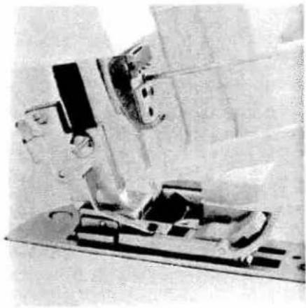
natural_image
Close-up of a sewing machine needle and fabric workpiece (no visible text or symbols)Changing the needle
Switch off the electrical power
To remove: Lower the presser foot and move the needle(s) to the highest position by turning the handwheel towards you. Push the needle inserting tool (from the accessory box 47) from below upward fully over the needle. Loosen the fastening screw of the needle (without removing it) with the Allen key (behind the swivel plate) and pull the needle down to remove.

natural_image
Close-up of a white, elongated object with a pointed tip, possibly a tool or device (no visible text or symbols)To insert: Insert the needle into hole E of the needle inserting tool, so that the flat needle shank K faces the flat side L of the inserting tool. Insert the needle fully into the holder and tighten the fastening screws. Remove the needle inserting tool.
natural_image
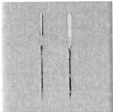
Two vertical cylindrical objects with textured surfaces, possibly tools or instruments (no visible text or symbols)Overlock needles types EL X 705, cat. no. 2002 are required for this machine.
natural_image
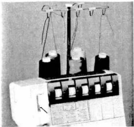
Black-and-white photo of a laboratory instrument with multiple spools and hanging weights (no visible text or labels)Threading the thread guides
Place the spools on the spool pins 35. You will find information on the thread net, thread unreeling disc, spool disc and cone thread adapter on pages 9 and 10. Thread through the thread guides 31 from the back to the front following the colored threading paths.
natural_image
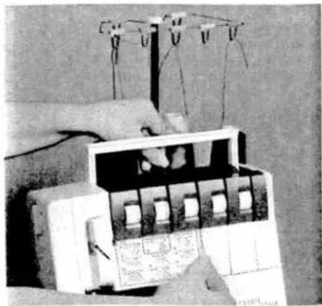
Close-up of hands operating a mechanical device with wires and components (no visible text or symbols)Lift the carry handle 3 upwards. Thread through the underside of the carrying handle and through the rear thread guides 44 using both hands to pull the thread down until it slips under the thread guide. Guide the thread through the tension discs and pull it down until it is positioned firmly between the tension discs. Return the carrying handle to its original position.

text_image
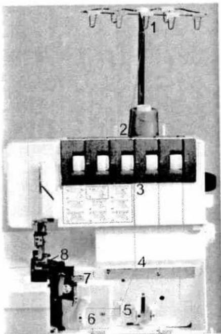
Diagram of a mechanical device with numbered components labeled 1 through 5Note:
Thread in a sequence of 1 to 5.
text_image
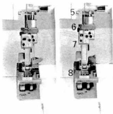
Technical diagram of an electrical component with numbered parts and labeled terminalsThreading the upper overedge looper (pink)
Turn the handwheel towards you until the upper overedge looper 18 is in its highest position. Thread in a sequence of 1 to 8.

text_image
8 7 1 4 6 5Thread through the thread guides 1 to 7, which are marked with a pink dot.

text_image
Labeled mechanical device image with numbered parts 6, 7, and 8 visibleThread from the front through the eye of the upper overedge looper 8. Pull approximately 4" (10 cm) of thread through the looper and place it to the left under the presser foot.

natural_image
Close-up of a mechanical assembly with visible gears and components (no text or symbols)Threading the lower overedge looper (yellow)
Turn the handwheel towards you until the lower overedge looper 19 is on the extreme right.
text_image
Technical diagram of a sewing machine with numbered components and labeled partsThread in a sequence of 1 to 10.

text_image
5 6 7 8Thread through the thread guides 1 to 8, marked yellow.

natural_image
Close-up of a mechanical device with a lever and base, no visible text or symbolsPress lever A downwards and hook the thread into guide B. Please also refer to the drawing below.
Note:
The lever returns automatically to its position as soon as you start sewing.

text_image
B C AThread from the front through the eye of the lower overedge looper C (= threading point 10).

natural_image
Black-and-white photo of a mechanical device with attached components, possibly a valve or actuator (no visible text or symbols)Pull approximately 4" (10 cm) of thread through the looper and place it to the left under the presser foot.

natural_image
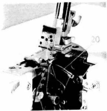
Close-up of a mechanical device with no visible text or symbolsThreading the two-thread chainstitch looper and cover stitch looper (violet) for the chainstitch
Turn the handwheel towards you until the two-thread chainstitch looper 20 is on the extreme right.
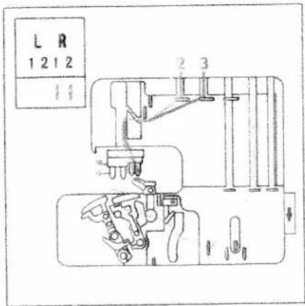
text_image
U U U U U 2 3 10 4 9 8 7 6 5Thread in a sequence of 1 to 11.
text_image
9 6 8 7 5 4Thread the thread guides which are marked with a violet square in a sequence of 1 to 9.

natural_image
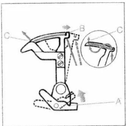
Interior view of a spacecraft with labeled components (A, B, C) and no visible text or symbols beyond labelsPush lever A upward and hook the thread into slot B. Also refer to the drawing below.
Note:
The lever returns automatically to its position as soon as you start sewing.
text_image
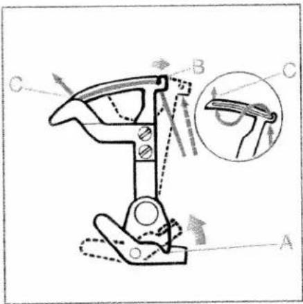
Technical diagram of a mechanical clamp mechanism with labeled parts A, B, C and directional arrows indicating motion or force.Thread from the front through eye C of the two-thread chainstitch looper and the cover stitch looper (= threading point 11).

natural_image
Close-up of a mechanical device with internal components and mounting brackets (no visible text or symbols)Pull approximately 4" (10 cm) of thread through the looper and place it to the left under the presser foot.
natural_image
Mechanical device with mounted components and wiring (no visible text or symbols)Exception:
Threading the two-thread chainstitch looper and cover stitch looper for the cover stitch (violet) (Prog. 02)
Turn the handwheel towards you until the two-thread chainstitch looper 20 is on the extreme right.

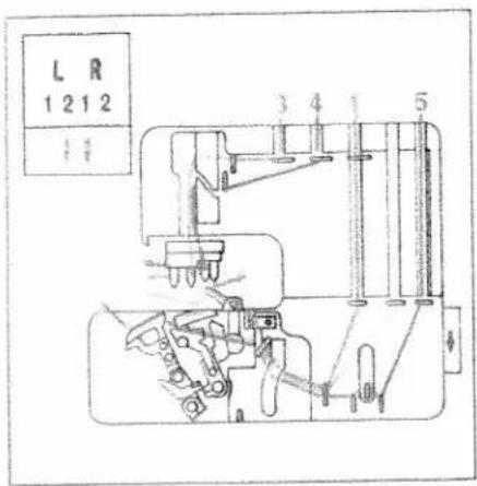
text_image
U U U U U 2 3 4 9 10 8 7 i6 5Thread in a sequence of 1 to 10.

text_image
Technical diagram of a mechanical assembly with numbered components and a small inset table showing part details.Thread the thread guides, as shown in the diagram, in a sequence of 1 to 8. Some of the threads guides are marked with a violet square.

natural_image
Black-and-white photo of a person in flight suit standing near equipment (no visible text or symbols)Press lever A upward and hook the thread into slot B. Also refer to the drawing below.
Note: The lever returns automatically to its position as soon as you start sewing.
text_image
Technical diagram of a mechanical clamp or bracket with labeled parts A, B, C and an inset showing a close-up view of the clamp.Thread from the front through eye C of the two-thread chainstitch looper and the cover stitch looper (= threading point 10).

natural_image
Close-up of a mechanical assembly with visible gears and bolts (no text or symbols)Pull approximately 4" (10 cm) of thread through the looper and place it to the left under the presser foot.

text_image
1 2 3 4 5 6 7 8 PFAFFThreading the needles
Thread in a sequence of 1 to 8.
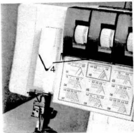
text_image
Close-up of industrial sewing machine with visible component labels and measurement indicatorsThe thread must be guided through the lower slot of thread guide 4.
text_image
Technical diagram of a mechanical valve assembly with numbered parts labeled 5 through 8Pull approximately 4" (10 cm) of thread through the looper and place it to the left under the presser foot.
Note:
For the cover stitch the thread must also be guided through the lower thread guide 7.

text_image
1 2 3 4 5 6 7 8 9 • PFAFF powerException:
Threading needle L2 when sewing a 5-thread safety-stitch seam (Prog. 09), a 4-thread safety-stitch seam (Prog. 08) and a 2-thread chainstitch (Prog. 01)
Thread in a sequence of 1 to 9.
text_image
5The thread must be guided through the upper slot of thread guide 5.

natural_image
Mechanical assembly device with cylindrical components and mounting base (no visible text or symbols)Pull approximately 4" (10 cm) of thread through the looper and place it to the left under the presser foot.

natural_image
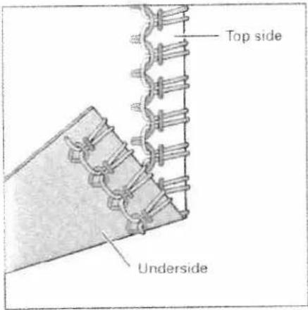
Technical line drawing of a mechanical assembly with no visible text or symbolsimportant note on threading
The needle(s) must always be threaded last so that the needle threads do not run under the looper thread as seen in drawing 1, but instead over the looper thread as depicted in drawing 2. Should this sequence not be followed, thread breakage or missed stitches can occur.

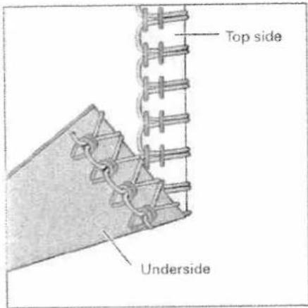
natural_image
Technical line drawing of a mechanical assembly with labeled parts (no readable text or symbols)If the looper threads break, you must pull the needle threads out of the needle eye, rethread the looper thread and then rethread the needle threads.

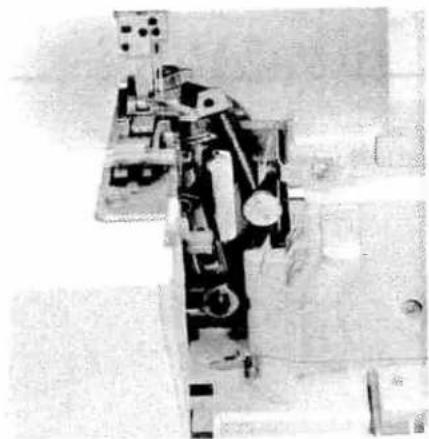
natural_image
Close-up of a textile machine with spools of thread and metal clamps (no visible text or symbols)Changing a spool on a threaded machine
Cut the threads off close to the spool and replace with new spools. Tie together the threads which are still in the machine with the new threads, and pull the threads out of the needle eyes. Raise the presser foot. Pull on the needle threads until the knots are about 6 inches (15 cm) past the last thread guide in front of the needles. Cut the knots off and pull the threads through the respective needle eyes. The looper threads can be pulled continuously past the looper eye and placed to the left underneath the presser foot.

natural_image
Close-up of hands operating a small electronic circuit board with wires, no visible text or symbolsNeedle threader
Move the needle(s) into the highest position and lower the presser foot. Place the thread from right to left in notch A of the needle threader (to be found in the accessory box). One of the two triangles must point upwards.

natural_image
Close-up of a sewing machine in a garment factory setting (no visible text or symbols)Place the needle threader onto the front groove of the needle. Slide the needle threader down to the needle eye and press it lightly against the needle.

natural_image
Industrial robotic arm with visible mechanical components and wiring (no text or symbols)A small metal pin is pushed through the needle eye and the needle is automatically threaded. Thread loops must be pulled to the back.
Overview of the threading paths and threading sequences
text_image
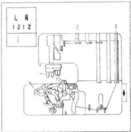
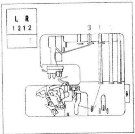
L R 1212 iProgram 01:
2-thread chainstitch
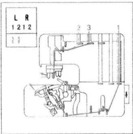
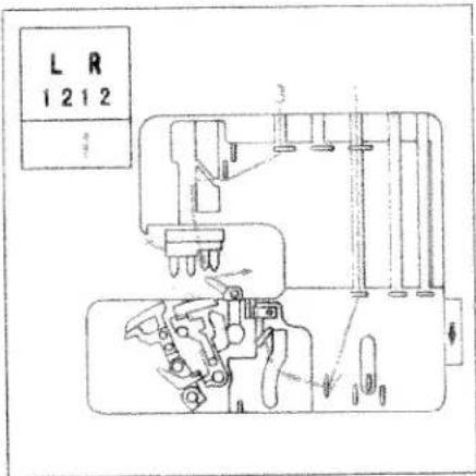
text_image
L R 1 2 1 2 11 2 3 1Program 02:
cover stitch
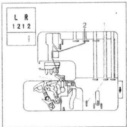
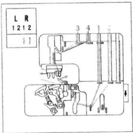
text_image
L R 1 2 1 2 3Program 03:
2-thread flatlock, narrow
Program 11:
2-thread serging, narrow
Program 12:
2-thread rolled hem
Program 13:
folded 2-thread rolled hem

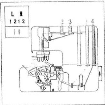
text_image
L R 1 2 1 2 3Program 04
2-thread flatlock, wide
Overview of the threading paths and threading sequences
text_image
L R 1 2 1 2 3 1Program 05:
3-thread overedge, narrow
Program 14:
3-thread rolled hem
Program 15:
folded 3-thread rolled hem
Program 16
3-thread flatlock, narrow
text_image
L R 1212Program 06:
3-thread overedge, wide
Program 17:
3-thread serging, wide
Program 18:
3-thread flatlock, wide
text_image
L R 1 2 1 2 1 1Program 07
4-thread overedge seam
text_image
L R 1 2 1 2 1 6Program 08:
4-thread safety-stitch seam
Overview of the threading paths and threading sequences
text_image
L R 1212 1 2 3 4 1 5Program 09:
5-thread safety-stitch seam
text_image
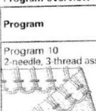
L R 1 2 1 2 1 1 2 3Program 10:
2-needle 3-thread assembly seam

natural_image
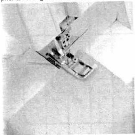
Close-up of a mechanical component with a circular hole and numbered features (no visible text or symbols)Presser foot pressure
The pre-set presser foot pressure on the machine is suitable for medium-heavy fabrics. The presser foot pressure does not need to be adjusted for most fabrics. If you are working with light or heavy fabrics then you may need to adjust the pressure. In this case, 6 setting positions are available which you can select using the adjusting knob for the presser foot pressure 17. The standard setting is "N".

natural_image
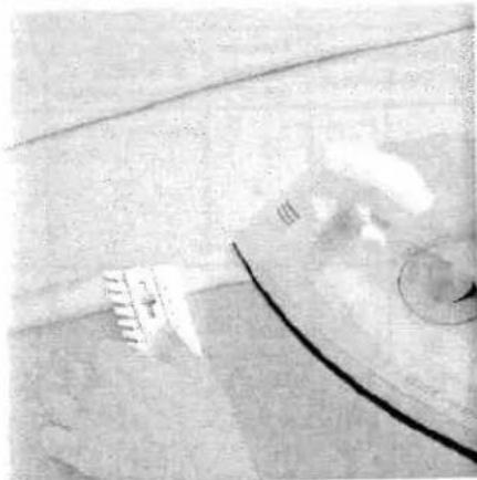
Black-and-white photo of a vintage sewing machine in the background (no visible text or symbols)Thread chain cutter
After finishing the seam, sew an approx. 6" - 8" (15 -20 cm) long thread chain. Pull the thread chain from the right to left over the thread chain cutter 33. This will cut off the thread chain.
natural_image
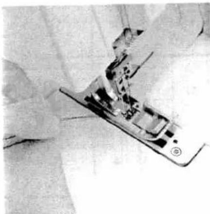
Close-up of a sewing machine with visible mechanical components (no text or symbols)Clamp spring for serging thread chain 25
Using this feature you can secure the thread chain at the start of the fabric by pulling it into the seam. Stitch off a minimum 4" (10 cm) long thread chain and raise the presser foot. Remove the thread chain carefully from the swiveling stitch width latch 22. Pull the thread chain forwards and clamp it under the spring.
natural_image
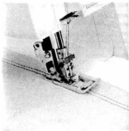
Close-up of a sewing machine needle stitching fabric, no visible text or symbolsButt the fabric up against the front of the needle(s). If necessary, make an approx. 1.5" (3 cm) cut into the fabric along the cut-line using a pair of scissors. Lower the presser foot and start sewing. The thread chain pulls automatically into the inside of the seam.
Note:
This feature cannot be used for either the 2-thread safety-stitch seam, the 4-thread safety-stitch seam, the 2-thread chainstitch or for the rolled hem.
natural_image
Close-up of a hand assembling electronic components on a circuit board (no visible text or symbols)Disengaging the upper blade
Switch off the electrical power
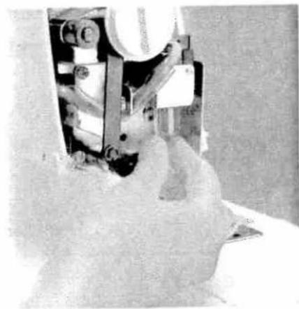
Move the movable upper blade 23 into its highest position by turning the handwheel towards you. Remove the waste container and open the looper cover and the swivel plate. Push the knob for lowering the upper blade 27 fully to the right.

natural_image
Close-up of a mechanical device with black components and mounting brackets (no visible text or symbols)To lower the upper blade turn the knob towards you until the upper blades clicks into place below. The upper blade is now disengaged.

natural_image
Close-up of a mechanical assembly with no visible text or symbolsEngaging the upper blade
Push the knob for lowering the upper blade to the right and swivel the blade back until it clicks into the operating position again. Close the looper cover and the swivel plate and reattach the waste container.
natural_image
Close-up of a mechanical assembly with no visible text or symbolsSwiveling stitch width latch
For standard overlock seams:
The swiveling stitch width latch 22 remains in the basic position when sewing all types of standard overlock seams (exception: Program 01, 02).

natural_image
Close-up of hands operating a black mechanical device (no visible text or symbols)For rolled hems:
Pull knob (A) to the right and swivel the swiveling stitch width latch 22 downwards.
natural_image
Close-up of a sewing machine needle stitching fabric (no visible text or symbols)This setting allows you to sew all types of rolled hems.
Attaching the converter Switch off the electrical power

natural_image
Mechanical assembly diagram showing internal components and parts (no visible text or labels)Position the upper overedge looper 18 right next to the needle by turning the hand-wheel towards you.
natural_image
Close-up of a hand operating a sewing machine needle (no visible text or symbols)Push the tip of the converter into the back side of the upper overedge looper until it clicks into place and push the converter onto the overedge looper bracket.

natural_image
Close-up of a mechanical device with wires and components, possibly a robotic arm or sensor (no visible text or symbols)To remove the converter, gently push the point of the converter from the eye of the upper overedge looper. You can now remove the converter by pulling it upwards from the overedge looper bracket.
text_image
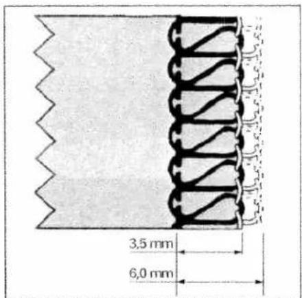
PFAFFSetting the seam width
The required seam width can be adjusted anywhere between 3.5 and 6 mm by turning the adjusting knob for seam width 13. The setting can be seen through the viewing window 14.
The two-thread chainstitch is sewn with a clearance of 6.5 to 9 mm.
natural_image
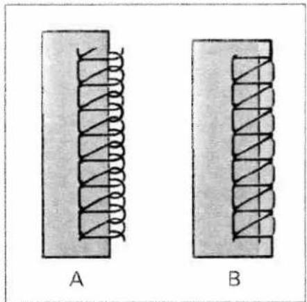
Two schematic diagrams of coiled solenoids labeled A and B, showing internal structure without any text or symbols.Illustration A: Should loops project out of the workpiece, move the movable upper blade 23 to the right by turning the seam width adjusting knob upwards.
Illustration B: Should the stitching be too tight, move the movable upper blade 23 to the left by turning the seam width adjusting knob downwards.

text_image
1,5 mm 4,0 mmNote:
The top row of numbers on the dial refers to the seam width of a standard 3-thread over-edge seam. The width settings 3.5mm through 6.0mm are measured from needle R1 to the outer fabric edge. This width is decreased by 2.0mm when only using needle R2, i.e. you have a seam width that is completely adjustable from 1.5mm to 4.0mm .
The bottom row of numbers refers to the seam of the 4 or 5-thread safety stitch seam. The width settings 6.5mm through 9mm are measured from needle L2 to the outer fabric edge.
Measurements are shown in metric and fractions.
text_image
3,5 mm 6,0 mm
natural_image
Close-up of a hand holding a small object, possibly a tool or device, with no visible text or symbols.Adjusting the machine to the cover stitch (Prog. 02) and two-thread chainstitch (Prog. 01)
This is only necessary if you do not want to trim the fabric edge. Insert the needle(s) (see page 13) according to the overview of the threading paths and threading sequences (see page 26). Open the looper cover and remove the blade guard 8 by pulling it towards you.
Lower the swiveling stitch width latch (see page 31) and disengage the upper blade (see page 30). Ensure that the upper blade is disengaged by turning the handwheel towards you.
natural_image
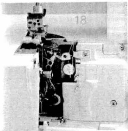
Close-up of a mechanical device with no visible text or symbolsDisengage the upper overedge looper. Move the upper overedge looper 18 into its lowest position by turning the handwheel towards you.
natural_image
Close-up of a mechanical component with a tool and bracket, no visible text or symbolsMove the looper disengaging lever 9 to the left. Ensure that the looper is disengaged by turning the handwheel towards you.
Thread the two-thread chainstitch looper and the cover stitch looper (see pages 18 to 21) and then the needle(s) (see page 22 and 23).
text_image
PFAFFPress the power table 45 downwards into the designated slot on the looper cover. Close looper cover.
Note:
Please ensure that the upper overedge looper is disengaged before attaching the power table 45.
natural_image
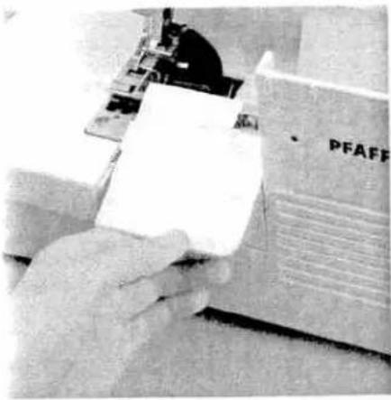
Close-up of a hand pressing down on a mechanical component (no visible text or symbols)To return the machine to its previous settings after sewing with the cover stitch or two-thread chainstitch:
Open the looper cover and remove the power table.

natural_image
Close-up of a hand operating a sewing machine (no visible text or symbols)Move the looper disengaging lever to the right, thus re-engaging the upper overedge looper.
Bring the swiveling stitch width latch into the basic position (see page 31) and engage the upper blade (see page 30).
Push the blade guard into the looper cover and close the looper cover.
natural_image
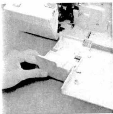
Close-up of a computer monitor with labeled parts A and B (no visible text or symbols on the device itself)Differential feed
The differential feed consists of two feed dogs (A + B), one behind the other, which feed the fabric. The movement of the front feed dog (A) and thus the amount of material to be fed can be regulated using the regulator wheel 41. The setting range is between 0.5 and 2.0.
The standard setting is 1.0, where the movement of the front feed dog (A) is synchronized with the rear feed dog (B). This means that the front feed dog feeds the same amount of fabric as the rear feed dog.
Note:
The function of the differential feed also depends on the set stitch length and the type of fabric being used.
natural_image
Close-up of a hand holding a circular gauge or dial, with no visible text or symbols on the dial itself.Set the regulator wheel for the differential feed 41 to 0.5. At this setting the front feed dog feeds half as fast as the rear feed dog. This means that the front feed dog feeds only half as much fabric as the rear feed dog, causing the fabric to stretch.
natural_image
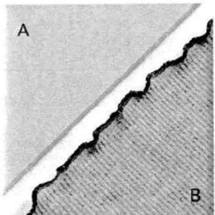
Close-up of a textured surface with labeled regions A and B, showing a wavy boundary and layered texture (no text or symbols beyond labels)Here you will avoid gathering/puckering of the seam when working with very light fabrics, such as silk and taffeta. Instead, a smooth seam (A) will be achieved.
You can also achieve decorative effects with the differential feed dog. For example the wavelike effect when using a rib knit (B).

natural_image
Close-up of hands holding a small white circular object with measurement markings (no readable text or symbols)Set the regulator wheel for the differential feed 41 to 2.0.
Here the front feed dog feeds twice as fast as the rear feed dog. This means that the front feed dog feeds twice as much fabric as the rear feed dog, causing the material to gather.
natural_image
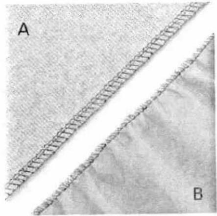
Close-up of two fabric strips labeled A and B, showing different textures and patterns (no text or symbols beyond labels)Here you will avoid stretching in the seam when working with knitwear, such as jerseys or gathered fabrics. Instead, a smooth seam (A) will be achieved.
You can also achieve decorative effects with the differential feed dog. For example the gathering effect when using very light fabrics (B).
The following table contains information on the differential feed settings. However, you should always test your setting first on a piece of scrap fabric.
| Type of fabric / effect | Differential feed setting | ||
| gather<2.0> | normal<1.0> | stretch<0.5> | |
| Very light fabrics: silk, satin, poplin, taffeta, linings. | ● | ● | |
| Normal fabrics: light and medium-heavy cottons, fine cords, thermal-wear. | ● | ||
| Light knitwear: jerseys, polo fabrics, cut-pile pullovers, tricot, fine knitwear and gathered fabrics. | ● | ● | |
| Heavy knitwear: sweatshirt fleece, heavy gathered fabrics, heavy knitwear. | ● | ||
| Stretch - wavelike effect: medium and light knitwear, jerseys, knitwear, ruffled sleeve and collar edges, skirt hems, dense stitch lengths. | ● | ||
| Gathering: ruffling light materials and lace, seam allowances for curves, arches on blouses, shirts, skirts, round pockets, flaps, stretching or gentle ruffling of arched sleeves (shoulders), sleeve widths for cuffs or gathered fabrics. | ● | ||
natural_image
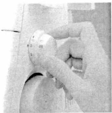
Close-up of a white spherical object with numbered markings, possibly a device or tool, held by hands (no readable text or symbols)Adjusting the stitch length
You can set the desired stitch length between 0.5 mm to 4.0 mm by turning the stitch length adjustment knob (42).
Note
For the two-thread chainstitch, the setting should be 3.0 or higher.
natural_image
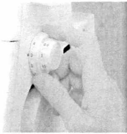
Close-up of a hand operating a mechanical device with a circular component (no visible text or symbols)Removing the needle plate
Raise the presser foot and move the needle(s) to the highest position. Remove the presser foot and open the swivel plate. Press down the needle plate disengaging lever 26. The needle plate 11 is raised out of its mount. The needle plate can be removed to the left.
Note:
The machine should be unthreaded when removing the needle plate.
natural_image
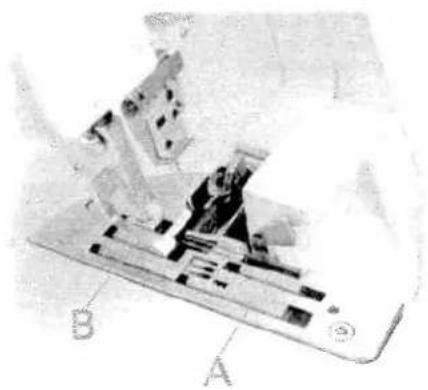
Black-and-white aerial view of a spacecraft or spacecraft in flight, showing its structural components and mission trajectory (no visible text or symbols)Inserting the needle plate
Place the needle plate to the rear on the guide pin (A) and press down at the front until you hear it click into place.

natural_image
Close-up of a hand using a tool to adjust or install electronic components (no visible text or symbols)Securing the upper blade
Switch off the electrical power
It is recommended to secure the movable upper blade 23 before sewing heavy fabrics. Raise the needle(s) to its highest position and open the swivel plate. Tighten the screw fully using the Allen key. This screw should always be slightly loosened again after sewing heavy fabrics.
Note:
The seam width can no longer be adjusted once the upper blade is secured.
natural_image
Aerial view of a row of rectangular structures with circular elements, possibly industrial tanks or storage units, on a grassy field (no visible text or symbols)Setting thread tension
The following pages contain directions for setting thread tensions for all programs. Adjust the tension by turning the tensioning wheel until the dot marker is at the desired setting.
The settings for adjusting thread tension are recommendations. Fabric type, thread quality and needle gauge will influence seam results. Always sew off a test seam onto a piece of scrap fabric and check the thread loops. Adjust the thread tension if necessary.
Adjusting the tension settings is described on pages 46 to 56.
Program overview
| Program | Application | Needle position | Stitch length | Stitch width | ||||
Program 012-thread chainstitch | Joining fabric layers where a traditional pressed-open seam is required. Also works well as a basting stitch for test-fitting garments. | 3-4 | 3.5 | |||||
Program 02Cover stitch | Sewing hems and fancy stitches. | 3-4 | 3.5 | |||||
Program 032-thread flatlock, narrow | Serging light fabrics. Joining stretch fabrics with a flatlock seam. | 2 | 5.5 | |||||
Program 042-thread flatlock, wide | Serging medium-heavy fabrics. Join-ing stretch fabrics with a flatlock seam. | 2 | 5.5 | |||||
Program 053-thread overedge narrow | Serging light (easily frayed) fabrics. | 2 | 5.5 | |||||
Program 063-thread overedge wide | Serging tightly woven (easily frayed) fabrics. | 3 | 5.5 | |||||
Program 074-thread overedge | Joining and simultaneous serging of all fabrics, in particular stretchy fabrics. | 2.5 | 5.5 | |||||
Program 084-thread safety-stitch seam | Joining and simultaneous serging of tightly woven fabrics. | 3 | 8.5 | |||||
Program 095-thread safety-stitch seam | Joining and simultaneous serging of tightly woven fabrics. | 3 | 8.5 | |||||
| ch width latch 22top □ = bottom | Looper disengaging lever 9 | Power table 50● = with○ = without | Converter 28■ = with□ = without | Thread tensionThe values refer to medium-leavy blocks and normal polyester thread | ||||
| blue | green | pink | yellow | violet | ||||
| 5.0 | 2.0 | |||||||
| 6.0 | 6.0 | 1.0 | ||||||
| 1.5 | 5.0 | |||||||
| 1.5 | 5.5 | |||||||
| 4.0 | 3.0 | 2.0 | ||||||
| 5.0 | 2.0 | 2.0 | ||||||
| 5.0 | 4.0 | 2.0 | 2.0 | |||||
| 5.0 | 1.5 | 5.5 | 2.0 | |||||
| 5.0 | 5.0 | 2.0 | 2.0 | 2.0 | ||||
Program overview
 | Application | Needle position | Stitch length | Stitch width | |||||
| sembly seam | Joining and simultaneous serging of light, very stretchy fabrics. | 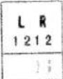 | 2 | 5.5 | |||||
| Program 112-thread serging, narrow | Serging light fabrics. | 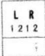 | 1.5 | 5.5 | |||||
| Program 122-thread rolled hem | Serging very light fabrics. Decorative edges. |  | 1-2 | 5.5 | |||||
| Program 13Folded 2-thread rolled hem | Serging very light fabrics. Decorative edges. | 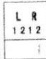 | 1-2 | 5.5 | |||||
| Program 143-thread rolled hem | Serging light to medium-heavy fabrics. Decorative edges. |  | 1-2 | 5.5 | |||||
| Program 15Folded 3-thread rolled hem | Serging light to medium-heavy fabrics. Decorative edges. |  | 1-2 | 5.5 | |||||
| Program 163-thread flatlock, narrow | Serging medium-heavy fabrics. Join-ing stretch fabrics with a flatlock seam and decorative edges. |  | 1.5 | 5.5 | |||||
| Program 173-thread serging, wide | Serging tightly woven (non-fraying) fabrics. |  | 2 | 5.5 | |||||
| Program 183-thread flatlock, wide | Joining stretch fabrics with a flatlock seam and decorative edges. |  | 2 | 5.5 | |||||
| ch width latch 22: top □ = bottom | Looper disengaging lever 9 | Power table 50 ● = with ○ = without | Converter 28 ■ = with □ = without | Thread tension The values refer to medium-heavy fabrics and normal polyester thread blue green pink yellow violet | |||||
| ■ | ▲ | ○ | ■ | 5.0 | 4.0 | 1.0 | |||
| ■ | ▲ | ○ | ■ | 4.0 | 1.0 | ||||
| □ | ▲ | ○ | ■ | 1.5 | 6.0 | ||||
| □ | ▲ | ○ | ■ | 4.0 | 4.0 | ||||
| □ | ▲ | ○ | □ | 5.0 | 4.0 | 3.0 | |||
| □ | ▲ | ○ | □ | 5.0 | 2.5 | 7.5 | |||
| ■ | ▲ | ○ | □ | 1.5 | 2.0 | 6.0 | |||
| ■ | ▲ | ○ | □ | 7.0 | 0.5 | 8.0 | |||
| ■ | ▲ | ○ | □ | 1.0 | 2.0 | 7.0 | |||
natural_image
Abstract 3D geometric shape with no visible text or symbolsImportant notes on sewing with the cover stitch
The power table is marked with various units of measurement. The upper figures are in cm. The lower figures are in inches.
Note: The hemmer guide H2 is available as an optional accessory. With this optional accessory you can hem your fabric effortlessly without having to press under the hem edge prior to sewing the cover stitch.
natural_image
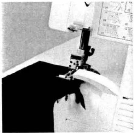
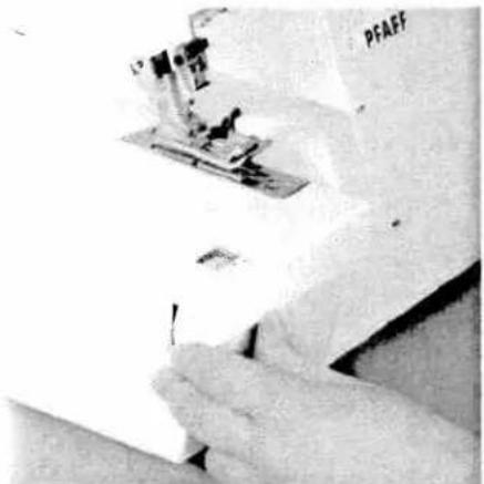
Close-up of a hand holding a small mechanical component, possibly a tool or device, with no visible text or symbols.To start sewing:
Raise the presser foot and place the fabric under the presser foot so the needles pierce the fabric for the first stitch. Position the fabric at the desired width using the marked guidelines on the power table. When starting to sew, pull the fabric taut towards the rear and sew slowly. The speed may be increased as you sew further along the fabric.
natural_image
Close-up of a medical device with a ruler and curved cable (no visible text or symbols)Preparing the fabric:
When not using the H2 optional accessory guide, it is useful to press under the fabric edge before hemming it. The width of fabric to be pressed under must be 0.5 cm wider than the finished hem width. Example: Press under a one inch (2.5 cm) fabric width to sew a finished hem of 3/4 inch (2 cm).
Note: Set the seam width at 3.5 cm.
natural_image
Close-up of hands using a sewing machine to cut fabric (no visible text or symbols)Finishing sewing:
- When sewing to the end of the fabric: Tightly hold the threads at the end of the seam. Sew slowly off the fabric while lightly pulling the threads toward the rear of the machine.
Note: The differential feed may need to be adjusted slightly to allow your fabric to lie perfectly smooth. Test your settings first on a piece of scrap fabric.
natural_image
Close-up of a sewing machine needle stitching fabric (no visible text or symbols)- If sewing on a tubular item, i.e. pant or sleeve hem:
Sew around tubular item, oversewing 4-5 stitches at the beginning of your seam. After the last stitch, turn the hand wheel towards you until the needles pierce the fabric and you have heard each needle "click" (just before the needles are in the lowest position).

natural_image
Close-up of a hand using a sewing machine to cut fabric (no visible text or symbols)After the second "click" turn the handwheel away from you until the needles are in their highest position. Raise the presser foot (this will release the tension on the threads). Hold the threads tightly at the end of the seam and pull the fabric from the machine. Cut the threads. Pull the threads through to the back of the fabric and knot them.

natural_image
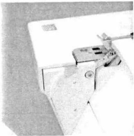
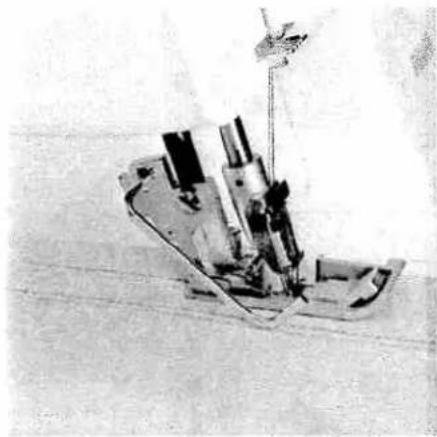
Mechanical device with clamped components mounted on a base plate (no visible text or symbols)Edge guide
Push the edge guide (included in your accessory box) into the guide holder A from the left. The edge guide can be set as required by sliding it to the left or right.
natural_image
Black-and-white photo of a mechanical device with attached wires and components (no visible text or symbols)The edge guide is useful for serging seams at regular intervals with the cover stitch or two-thread chainstitch.
text_image
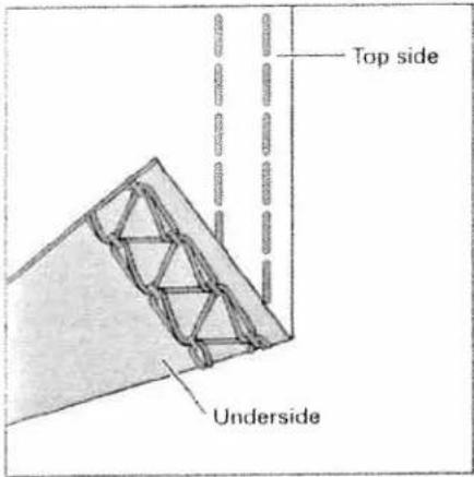
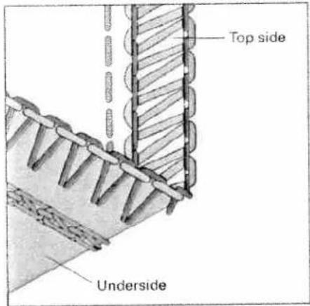
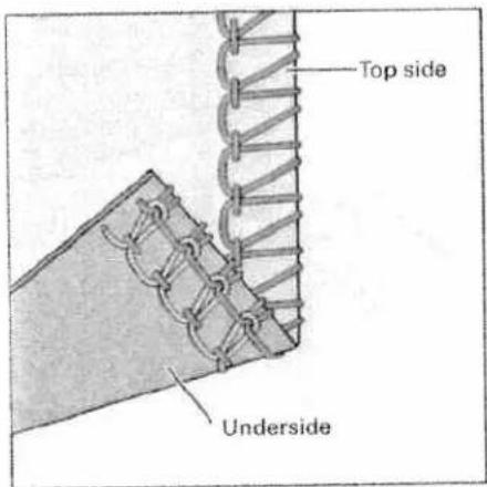
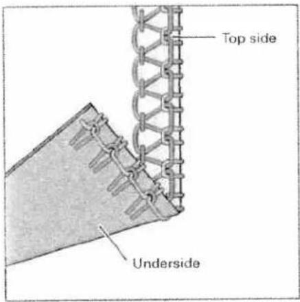
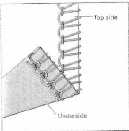
Top side UndersideStitch formation correction measures
cover stitch
Program 02
When all tensions are correctly set, the needle threads (green and blue) are just slightly visible on the underside of the fabric. The looper thread (violet) is situated loosely in between.
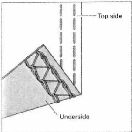
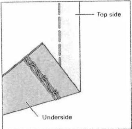
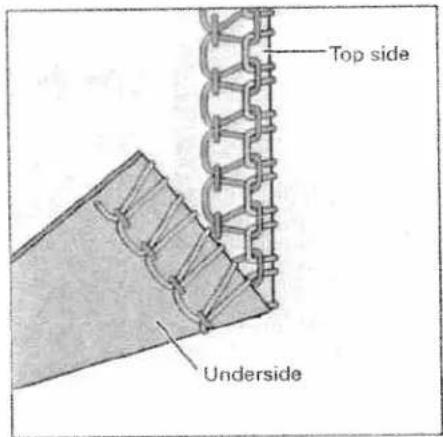
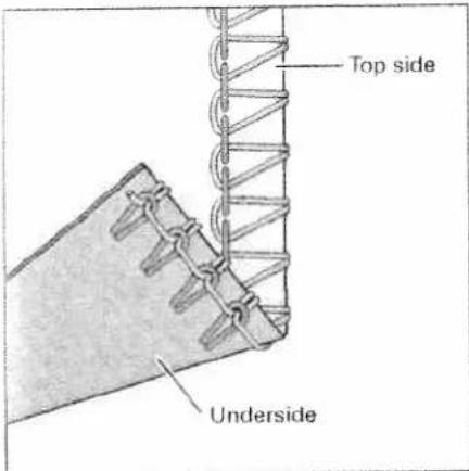
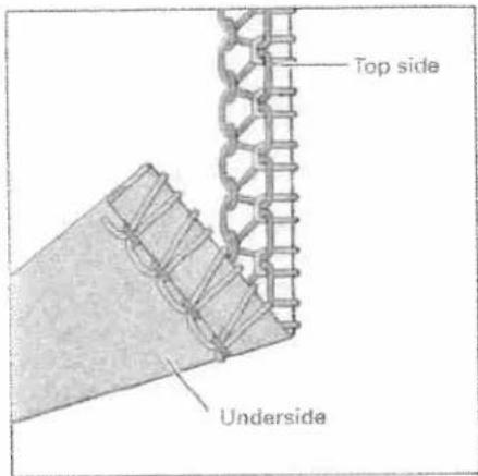
text_image
Top side UndersideThe right needle thread (green) is too loose, causing large loops on the underside of the fabric.
Set the green thread tension to a higher value.

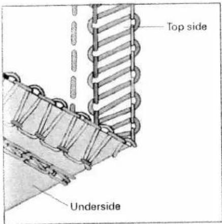
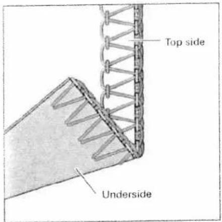
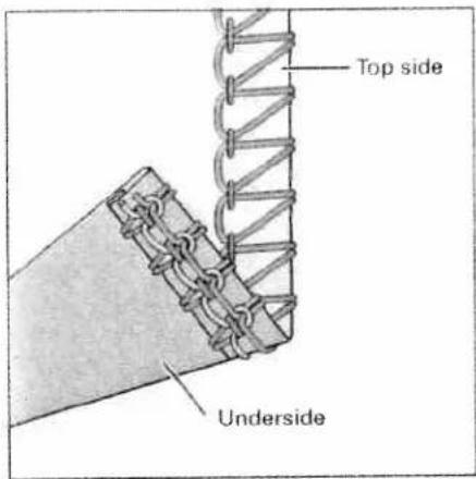
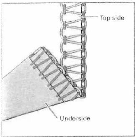
text_image
Top side UndersideThe needle threads (green and blue) are set too tightly causing folds in the fabric.
Set the green and blue thread tension to a lower value.
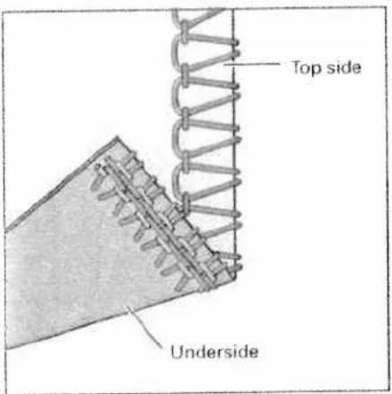
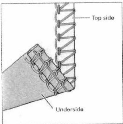
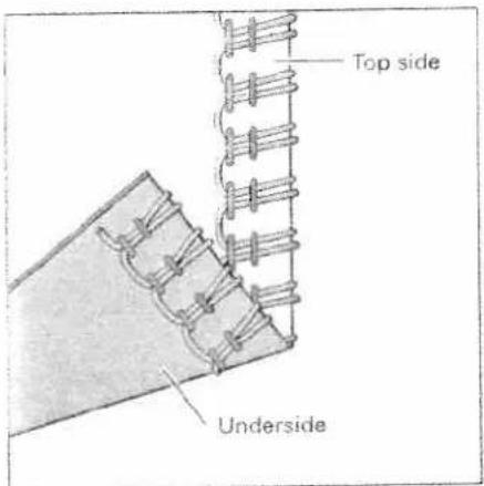
text_image
Top side Underside5-thread safety-stitch seam
Program 09
Since the 5-thread safety-stitch seam consists of the 2-thread chainstitch and the 3-thread overedge seam, you can refer to the correction possibilities of these seams below and on page 49.
text_image
Top side Underside4-thread safety-stitch seam
Program 08
Since the 4-thread safety-stitch seam consists of the 2-thread chainstitch and the
2-thread flatlock, you can refer to the correction possibilities of these seams below and on page 51.
Note: Attach the converter (see page 32), when sewing a 4-thread safety-stitch seam.

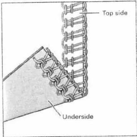
text_image
Top side Underside2-thread chainstitch
Program 01
When all tensions are correctly set, the needle thread (blue) is just slightly visible on the underside of the fabric.
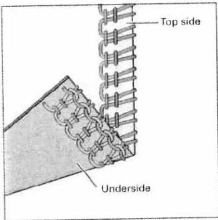
text_image
Top side UndersideThe needle thread (blue) is too loose, causing larger needle thread loops on the underside of the fabric.
Set the blue thread tension to a higher value.

text_image
Top side Underside4-thread overedge seam
Program 07
When all tensions are correctly set, the loops of both looper threads (pink and yellow) are directly on the edge of the fabric.
text_image
Top side UndersideThe needle threads (blue and green) are too loose, causing larger loops of needle thread on the underside of the fabric.
Set the blue and green thread tension to a higher value.
text_image
Top side UndersideThe upper looper thread (pink) appears on the underside of the fabric.
Set the pink thread tension to a higher value and/or the yellow thread tension to a lower value.

text_image
Top side UndersideThe lower looper thread (yellow) appears on the top side of the fabric.
Set the yellow thread tension to a higher value and/or the pink thread tension to a lower value.

text_image
Top side Underside3-thread overedge seam
narrow and wide
Program 05 and 06
When all tensions are correctly set, the loops of both looper threads (pink and yellow) are directly on the edge of the fabric.

text_image
Top side UndersideThe needle thread is too loose, causing loops on the underside of the fabric.
Set the relevant needle thread tension to a higher value.
text_image
Top side UndersideThe upper looper thread (pink) appears on the underside of the fabric.
Set the pink thread tension to a higher value and/or the yellow thread tension to a lower value.
text_image
Top side UndersideThe lower looper thread (yellow) appears on the top side of the fabric.
Set the yellow thread tension to a higher value and/or the pink thread tension to a lower value.
text_image
Top side Underside3-thread flatlock
narrow and wide
Program 16 and 18

text_image
Top side UndersideThe needle thread is too tight.
Set the needle thread tension (blue) to a lower value.
text_image
Top side UndersideThe upper looper thread (pink) appears on the underside of the fabric.
Set the pink thread tension to a higher value.
text_image
Top side UndersideThe lower looper thread (yellow) is too loose.
Set the yellow thread tension to a higher value.
text_image
Top side Underside2-thread flatlock
narrow and wide
Program 03 and 04
When all tensions are correctly set, the loops of both threads are directly on the underside of the fabric.
Note: The converter (see page 32) must be attached to sew the 2-thread flatlock seam.

text_image
Top side UndersideThe needle thread is too loose or the lower looper thread (yellow) is too tight.
Set the relevant needle thread tension to a higher value and/or the yellow thread tension to a lower value.

text_image
Top side UndersideThe lower looper thread (yellow) is too loose and/or the needle thread is too tight.
Set the yellow thread tension to a higher value and/or the relevant needle thread tension to a lower value.

text_image
Top side Underside3-thread rolled hem
Program 14
text_image
Top side UndersideThe upper needle thread (green) is too loose.
Set the green thread tension to a higher value.
text_image
Top side UndersideThe upper looper thread (pink) appears on the underside of the fabric.
Set the pink thread tension to a higher value and/or the yellow thread tension to a lower value.

text_image
Top side UndersideThe lower looper thread (yellow) appears on the top side of the fabric.
Set the yellow thread tension to a higher value and/or the pink thread tension to a lower value.
text_image
Top side Underside3-thread rolled hem (folded) Program 15

text_image
Top side UndersideThe upper needle thread (green) is too loose. Set the green thread tension to a higher value.

text_image
Top side UndersideThe upper looper thread (pink) only partly loops around the fabric edge.
Set the pink thread tension to a lower value and/or the yellow thread tension to a higher value.
text_image
Top side UndersideThe lower looper thread (yellow) appears on the top side of the fabric.
Set the yellow thread tension to a higher value and/or the pink one to a lower value.
text_image
Top side Underside2-thread rolled hem
Program 12
Note: The converter (see page 32) must be attached to sew the 2-thread rolled hem.

text_image
Top side UndersideThe upper needle thread (green) is too tight. Set the green thread tension to a lower value and/or the yellow thread tension to a higher value.

text_image
Top side UndersideThe lower looper thread (yellow) is too tight. Set the yellow thread tension to a lower value and/or the green thread tension to a higher value.

text_image
Top side Underside2-thread rolled hem (folded)
Program 13
Note: The converter (see page 32) must be attached to sew the 2-thread rolled hem.

text_image
Top side UndersideThe upper needle thread (green) is too loose.
Set the green thread tension to a higher value and/or the yellow thread tension to a lower value.

text_image
Top side UndersideThe lower looper thread (yellow) is too loose.
Set the yellow thread tension too a higher value.
text_image
Top side Underside2-needle 3-thread assembly seam
Program 10
Note: The converter (see page 32) must be attached to sew the 2-needle 3-thread assembly seam.
text_image
Top side UndersideThe lower needle thread (blue) is too loose. Set the blue thread tension to a higher value.

text_image
Top side UndersideThe upper needle thread (green) is too loose.
Set the green thread tension to a higher value.
text_image
Top side UndersideThe lower looper thread (yellow) is too tight.
Set the yellow thread tension to a lower value.
| Thread chart for 2-, 3- and 4-thread overedge seams | ||
| Fabric | Thread | Stitch length |
| Light fabrics:organdy, fine knitwear,taffeta, silk,lining fabrics | Cotton no. 50 - 70Synthetic thread no. 70 - 140 | 2.0 - 4.0 mm |
| Medium-heavy fabrics:cotton, tricot, linen,dress fabrics | Cotton no. 40 - 60Synthetic thread no. 70 - 140 | 2.0 - 4.0 mm |
| Heavy fabrics:tweed, suit fabrics,denim, heavy cloth | Cotton no. 30 - 50Synthetic thread no. 70 - 140 | 2.0 - 4.0 mm |
| Knitwear: | Cotton no. 40 - 60Synthetic thread no. 70 - 140 | 2.0 - 4.0 mm |
| 2 or 3-thread rolled hems | Polyester thread no. 120 - 140Mercerized thread (bulk thread) | 1.0 - 2.0 mm |

natural_image
Close-up of a sewing machine needle stitching fabric, with a hand adjusting the component (no visible text or symbols)Machine maintenance
Cleaning the machine
Switch off the electrical power
Remove the waste container and open the looper cover and swivel plate. Disengage the upper blade (see page 30) and remove the presser foot and the needle plate.
Use the accessory brush provided to remove any waste thread from the upper and lower blades, the differential feed and the looper area.
natural_image
Interior view of a mechanical device with internal components (no visible text or symbols)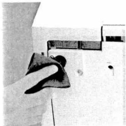
natural_image
Close-up of a hand cleaning a white door with a cloth (no visible text or symbols)Lubricating the machine
Switch off the electrical power
Move the upper overedge looper into its highest position. Lubricate the points shown above with the oil provided (located in the accessory box) every time you clean the machine. One or two drops of PFAFF sewing machine oil are sufficient. All other parts are manufactured from special materials and do not require any lubrication.
Cleaning the rubber feet
Clean the rubber feet from time to time with alcohol. This ensures good stability.
natural_image
Close-up of a sewing machine needle with visible mechanical components (no text or symbols)Changing the upper blade
Switch off the electrical power
To remove: Set the adjusting knob for seam width to 3.5 mm. Fasten the upper blade (see page 39) before loosening the fastening screw (A) with the wrench provided in the accessory box. Then remove the upper blade.

natural_image
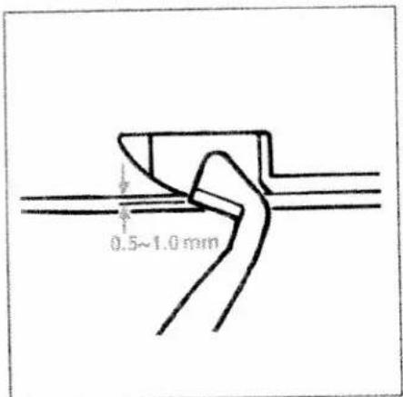
Close-up of a sewing machine needle with visible mechanical components (no text or symbols)To insert: Attach the new upper blade and gently tighten the fastening screw. Then turn the handwheel until the upper blade is in the lowest position.
text_image
0.5~1.0 mmIn this position the front edge of the upper blade must be 0.5 to 1.0 mm lower than the cutting edge of the lower blade. When the upper blade has been properly inserted you can fully tighten the fastening screw. Loosen the screw to the movable upper blade.
natural_image
Close-up of a sewing machine in operation, no visible text or symbolsChanging the light bulb
Switch off the electrical power
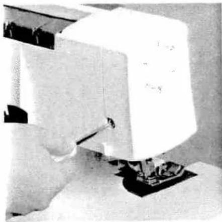
Using the screw driver in the accessory box loosen the fastening screw to the sewing light cover 16 until the cover can be removed.
natural_image
Close-up of a hand operating a mechanical device with no visible text or symbolsPush the light bulb fully into its socket. Rotate counter-clockwise through half a turn and remove.
natural_image
Close-up of a mechanical device with no visible text or symbolsGuide the new light bulb (max. 15 W) into the socket and twist until both pins on the bulb click into place. Press the bulb right into the socket, twisting it clockwise until it is securely fixed.
Replace the sewing light cover and tighten the fastening screw.
Sewing problems and their solutions
This machine has been developed with ease of operation in mind. No difficult or tricky settings need to be made. Sewing problems of the kind described below may occur as a result of minor adjustment and operating errors. They can be easily adjusted by following the instructions.
| Problem | Cause | Solution |
| Needle breakage | The needle was bent or the point damaged.The needle was not fully inserted.The fabric was pulled too firmly. | Insert new needle(see page 13).Insert needle fully(see page 13).Do not pull on the fabric when sewing. |
| Thread breaks | Incorrectly threaded.Thread has caught.Thread tension is too tight.Needle not fully inserted.Incorrect needle used. | Thread properly (see page 14 - 23).Check if the thread is caught on the spool stand etc.Correct the tension (see page 46 - 56).Insert needle correctly(see page 13).Use needle system EL X 705. |
| Skipping stitches | Needle bent or point damaged.Needle not fully inserted.Incorrect needle used.Incorrectly threaded. | Insert new needle(see page 13).Insert needle correctly(see page 13).Use needle system EL X 705.Thread correctly(see page 14 - 23). |
| Stitch formation faulty | Incorrect setting of thread tensions | Re-set thread tensions (see page 46 - 56). |
| 3 or 4 thread overedge seam has an irregular appearance and the upper looper thread has not interlocked in the seam. | The converter is attached. | The converter must be removed (see page 32). |
| Machine will not operate although master switch is on. | Power supply interrupted | Close looper cover(see page 8). |
| Fabric not neatly trimmed | Waste thread between upper and lower bladeUpper blade is blunt. | Clean blades.Replace upper blade(see page 59). |
| Puckered seams | Thread tension too tight.Incorrect setting of differential feed.Thread has caught due to incorrect threading. | Reduce thread tension.Re-adjust differential feed(see pages 36, 37).Thread correctly(see pages 14 - 23). |
| Fabric not fed through evenly | Stitches too short.Sewing foot pressure too low for heavy fabrics.Sewing foot pressure too high for lightweight fabrics. | Increase stitch length(see page 38).Increase sewing foot pressure(see page 28).Reduce sewing foot pressure(see page 28). |
Optional accessories
This machine offers a wide range of optional accessories for special serging details. Consult your PFAFF dealer.
| Optional accessory | Order No. | Use |
| Multi-purpose foot M | 29 924 993 82-002 | Foot, to which guides H1, H2 and H3 can be attached. |
| Lace and braiding guide H1 | 29 924 993 82-003 | Guide for applying lace or braiding (to the under side of the fabric). |
| Hemmer guide H2 | 29 924 993 82-001 | Guide for hemming/turns under one inch while serging. |
| Bias-tape guide H3 | 29 924 993 82-004 | Guide for applying bias tape as edging. |
| Clear foot N | 29 924 993 82-006 | Presser foot with groove.It can be used together with guide N1. |
| Fancy-stitch guide N1 | 29 924 993 82-007 | For stitching down a double chainstitch or a 3-thread overedge seam and for decorative effects. |
| Faggoting guide F2 | 29 924 993 82-008 | Guide for edge joining two pieces of fabric with consistent clearance. Use transparent presser foot F from the accessory box. |
| Lace guide F3 | 29 924 993 82-005 | Guide for applying lace (on the top side of the fabric). Use transparent presser foot F from the accessory box. |
| Flat-felled-seam guide F4 | 29 924 993 82-009 | Guide for sewing flat-felled seams.Use transparent presser foot F from the accessory box. |
| Cording foot K | 29 924 993 82-011 | For serging pintucks with the cording tongue K1 and the guide K2. |
| Cording tongue K1 | 29 924 993 82-012 | For serging pintucks. |
| Cording guide K2 | 29 924 993 82-010 | For serging pintucks with gimp thread. |
| Strap and belt-loop foot L | 29 924 993 82-013 | For sewing belt loops and straps, and for ornamental stitches with a cover stitch. |
| Universal tape binder | 29 924 993 82-014 | For binding fabric edges with various widths of pre-made bias tape. |
| Beading foot P | 29 924 993 82-015 | For serging on beading and sequins. |
| Bead needle plate P | 29 924 993 82-016 | The bead needle plate P together with the beading foot P allows you to serge on beading and make a rolled hem simultaneously. |
| Multi-purpose foot C | 29 924 993 82-017 | For sewing on bands, elastic tape, elastic thread and fishing line together with the various elastic tape inserts. |
| Elastic tape insert 7.5 mm | 29 924 993 82-034 | For sewing on elastic tape with a width up to 7.5 mm. |
| Elastic tape insert 10 mm | 29 924 993 82-035 | For sewing on elastic tape with a width from 7.5 mm - 10 mm. |
| Elastic tape insert 13 mm | 29 924 993 82-036 | For sewing on elastic tape with a width from 10 mm - 13 mm. |
| Shirring/ Gathering foot G | 29 924 993 82-018 | For shirring/gathering and joining two pieces of fabric simultaneously. |
| Blindstitch foot D | 29 924 993 82-019 | For serging blind hems and ornamental seams. |
| Band and braiding foot Q | 29 924 993 82-020 | For sewing on bands and braiding. Gimp cords and thread and bands with decorative threads can be stitched over using this foot together with guide K2. |
| Piping and welting foot E | 29 924 993 82-028 | Presser foot for guiding and sewing in piping and welting. |
| Accessory holder | 29 924 993 82-021 | Holder, to which the following accessories together with the retaining screw and the swiveling arm can be attached. |
| Retaining screw | 29 924 993 82-023 | For securing the following accessories to the accessory holder. |
| Edge guide with units of measurement | 29 924 993 82-022 | For guiding the fabric edge and measuring cut widths and seam widths simultaneously (use the machine's standard presser foot). |
| Gathering/Shirring tongue | 29 924 993 82-027 | For gathering/shirring and joining two pieces of fabric simultaneously (use the machine's standard presser foot). |
| Tape binder 40 mm | 29 924 993 82-031 | For binding the fabric edge with 40 mm tape. Binding width 10 - 12 mm. (Use the machine's standard presser foot.) |
| Swiveling arm | 29 924 993 82-024 | For attaching the following accessories to the accessory holder. |
| Curved-seam guide | 29 924 993 82-025 | For serging a curved piece to a straight piece of fabric (use the machine's standard presser foot). |
| Piping and welting accessory | 29 924 993 82-030 | Together with piping foot E, for binding and guiding piping and gimp between two layers of fabric. |
Specifications
| Maximum sewing speed | 1300 stitches/min. |
| Seam width | 1.4 mm - 9.0 mm |
| Cover stitch width | 5 mm |
| Stitch length | 0.5 mm - 4 mm |
| Presser foot | exchangeable |
| Lubrication | manual |
| Presser foot height | 4.5 mm |
| Overedge stroke | 2.0 mm |
| Needle system | EL X 705, cat no. 2002 |
| Needle size | 80/12, 90/14 |
| Number of threads | 2, 3, 4, 5 |
| Dimensions (width x height x depth) | 355 x 290 x 300 mm |
| Weight | 8.6 kg |
Packing contents
| 1 machine |
| 1 foot control |
| 1 instruction manual/guarantee card |
| 1 machine cover |
| 1 accessory box |
| 1 power table |
We reserve the right to change the machine equipment and the assortment of accessories without prior notice, or make modifications to the performance or design.
Such modifications, however, will always be to the benefit of the user and the product.
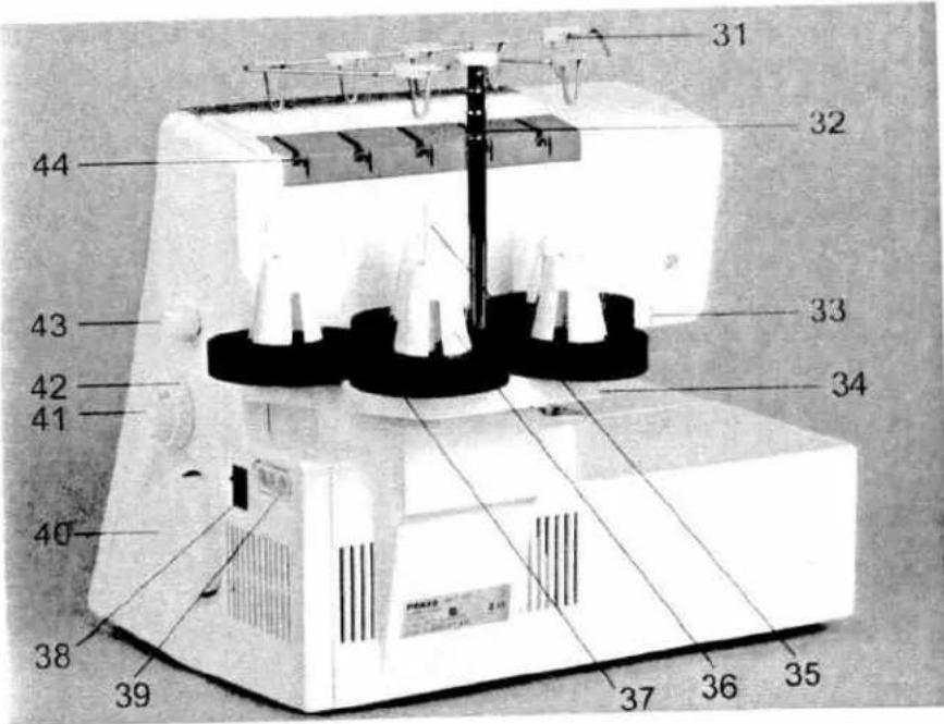
Parts of the coverstyle
31 Thread guides with color coding
32 Telescoping thread guide
33 Thread chain cutter
34 Thread spool stand
35 Thread spool pin
36 Cone thread adapter
37 Spool disc
38 Electrical power master switch
39 Machine socket, foot control
40 Handwheel
41 Regulator wheel for differential feed
42 Stitch length adjustment knob
43 Presser foot lifter
44 Rear thread guides
45 Power table
46 Foot control
47 Accessory box
text_image
31 32 44 33 43 34 42 41 40 38 39 37 36 35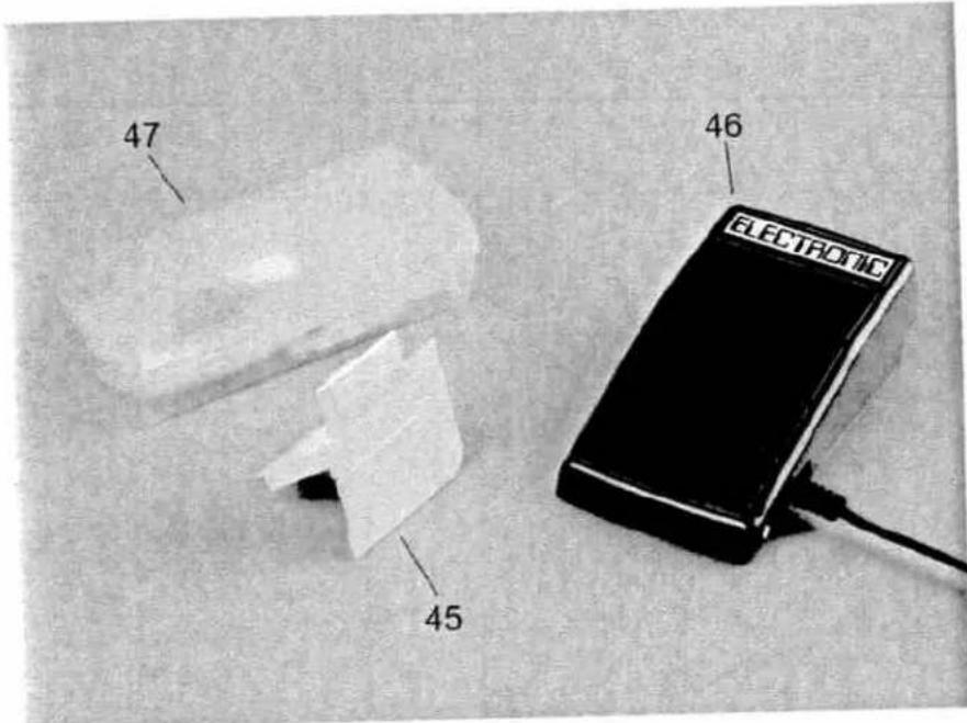
text_image
47 45 46 ELECTRIC