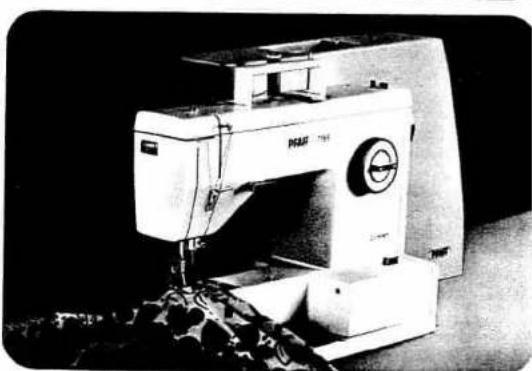
1199 - Sewing machine PFAFF - Free user manual and instructions
Find the device manual for free 1199 PFAFF in PDF.

User questions about 1199 PFAFF
0 question about this device. Answer the ones you know or ask your own.
Ask a new question about this device
Download the instructions for your Sewing machine in PDF format for free! Find your manual 1199 - PFAFF and take your electronic device back in hand. On this page are published all the documents necessary for the use of your device. 1199 by PFAFF.
USER MANUAL 1199 PFAFF
natural_image
Circular mechanical dial with measurement markings and a central pointer (no readable text or symbols)
text_image
W STT == A A B/M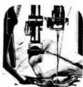
natural_image
Black-and-white photo of a sewing machine with visible brand name 'PAAF' and control knob (no additional text or symbols)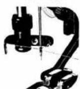
PFAFF-HANDELSGESELLSCHAFT
natural_image
Line drawing of a PFAFF sewing machine with no visible text or symbols on the device itself
text_image
PFAFF CompactTurs of your sewing machine
Some safety rules
a) Be careful when sewing that your fingers will not be injured by the needle.
b) Make sure you pull out the power cord plug whenever you want to change needle, sewing foot, bobbin or needle plate, when you clean and oil the machine, or when you have to interrupt sewing and leave the machine for a while.
1 Take-up lever
2 Thread retainer stud
3 Eraser button
4 Utility-stitch buttons
5 Spool pins
6 Bobbin winder
7 Balance whe
8 Stop motion knob
9 Ultra-Matic stitch selector
10 Needle position and buttonhole control
11 Master switch
12 Base (of portable machines)
13 Bed cover
14 Sewing foot
15 Thread cutter (on presser bar) On Model 1209 dual feed with thread cutter
16 Upper tension
17 Control for reverse sewing and dropping the feed dog
18 Presser bar lifter (on back of machine arm)
19 Needle holder with needle set screw
20 Needle plate with guide grooves
21 Handle on Models 1199/1209
22 Accessories drawer on Models 1199/1209
23 Free arm
24 Free arm cover (enclosing sewing hook)
25 Needle thread control
IMPORTANT!
Valid for United Kingdom only!
The wires in this mains lead are coloured in accordance with the following code: Blue: Neutral: Brown: Live.
As the colours of the wires in the mains lead of this appliance may not correspond with the coloured markings identifying the terminals in your plug, proceed as follows:
The wire which is coloured blue must be connected to the terminal which is marked with the letter N or coloured black.
The wire which is coloured brown must be connected to the terminal which is marked with the letter L or coloured red.
Please note:
When 13 amperes plug is used a
3 amperes fuse has to be fitted.
Model 1196/1197
Press down catches A (marked by arrows) and swing them outwards. Then lift the cover off.
To replace the cover, reverse this sequence. To open the sewing box lift catches B. Then open the top cover sections.
Models 1196 (A), 1197 (B)
Remove this receptacle from the machine. Before you put the machine away after sewing, replace the receptacle in its original position. On model 1196 place it on the bedplate, on model 1197 push it into the free arm.
Contents
| Removing the carrying case cover, 1196/1197 | 1 |
| Foot control receptacle, 1196/1197 | 1 |
| Removing the carrying case cover, 1199/1209 | 2 |
| Foot control receptacle, 1199/1209 | 2 |
| Handle, 1199/1209 | 2 |
| Accessories drawer, 1199/1209 | 3 |
| Electrical connection | 4 |
| Foot control | 4 |
| Removing bobbin case and bobbin | 5 |
| Disengaging the sewing mechanism | 5 |
| Bobbin winding | 6 |
| Inserting the bobbin | 6 |
| Inserting the bobbin case | 7 |
| Upper threading | 7 |
| Threading the needle 1196-1199 | 8 |
| Drawing up the bobbin thread | 8 |
| Attaching the work support | 9 |
| Thread cutter | 10 |
| Ultra-Matic stitch selector (9) | 11 |
| Straight stitch | 11 |
| Zigzag stitch | 11 |
| Needle position | 12 |
| Reverse sewing and dropping the feed dog | 12 |
| Presser bar lifter | 13 |
| Dual feed, 1209 | 13 |
| Thread tensions | 14 |
| Changing the needle | 15 |
| Changing the sewing foot | 15 |
| Utility stitches | 16 |
| Utility-stitch combinations | 17 |
| Sewing buttonholes | 18 |
| Sewing feet | 20 |
| Special accessories | 21 |
| Changing the light bulb | 22 |
| Cleaning and oiling | 22 |
| Threading the needle 1209 | 23 |
| Trouble shooting | 24 |
text_image
A B A B -
natural_image
Technical line drawing of an internal battery housing with internal components (no text or symbols)
natural_image
Line drawing of a mechanical device with a base and cable, no text or symbols present
natural_image
Technical line drawing of an electronic device with a card and housing (no text or symbols)E
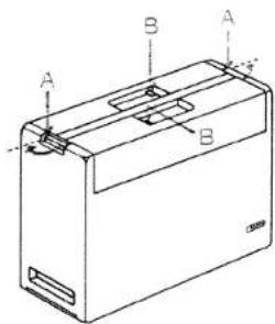
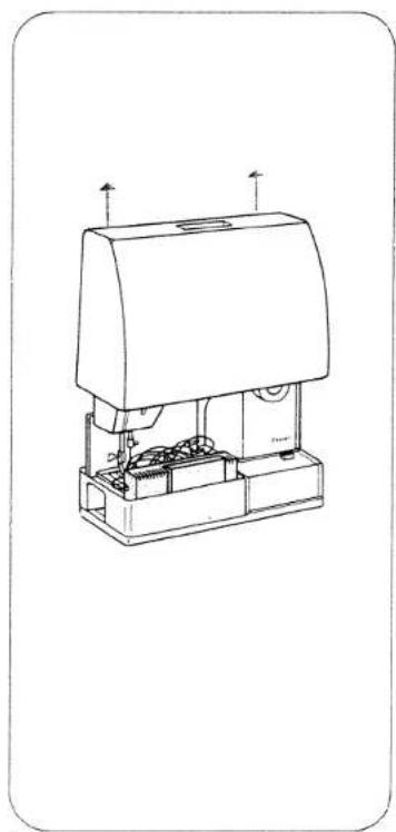
Removing the carrying case cover, Model 1199/1209
On the Compact models the carrying case cover is not locked in position by catches and can thus be easily lifted off.
Foot control receptacle Models 1199/1209
Remove the receptacle from the machine. Before you put the machine away after sewing, replace the receptacle in its original position (A), and push it onto the free arm.
Handle, Model 1199/1209
The handle can be folded down, as shown by the arrow in ill. B.
Accessories drawer, Model 1199/1209
On the Compact models the accessories are kept in a drawer. Push the catch upwards a little (A) and at the same time pull drawer 22 out of the machine (B).
JII.C shows how the accessories are to be placed in the drawer.
natural_image
Line drawing of a mechanical device with no visible text or symbols
natural_image
Line drawing of a device with a card and connector (no text or symbols)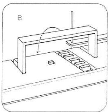
natural_image
Technical line drawing of a mechanical assembly with stairs and a lever (no text or symbols)
text_image
Compact A 22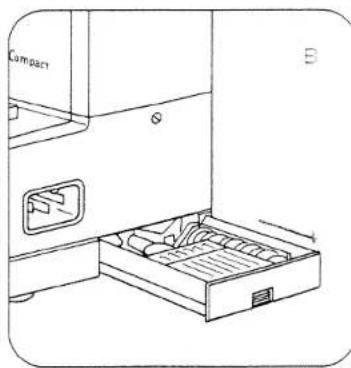
natural_image
Line drawing of a portable refrigerator with drawer and door panel (no text or symbols)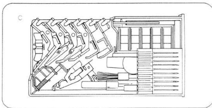
natural_image
Technical line drawing of a mechanical tool holder with multiple clamps and a tray (no text or labels)Electrical connection
Push plug A into the machine socket and plug B into the wall socket. Press master switch 11. Your machine is now switched on and ready for sewing.
Foot control
Place the foot control under the table. Press down its pedal. The machine starts sewing. The more the pedal is depressed, the faster the machine will run.
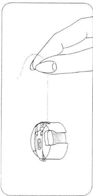
Removing bobbin case and bobbin
Raise the needle. Remove bed cover 13 or open free arm cap 24. Lift latch K, pull out the bobbin case, release the latch and take out the bobbin. The bobbin cannot fall out as long as you keep latch K raised.
Disengaging the sewing mechanism
Before you start winding the bobbin, disengage the sewing mechanism. To do this, hold the balance wheel steady and turn the stop motion knob toward you. After bobbin winding, turn the knob in the opposite direction to re-engage the sewing mechanism again.

natural_image
Technical line drawing of a mechanical device with attached cable and socket (no text or symbols)4

natural_image
Technical line drawing of a mechanical device with attached cable and connector (no text or symbols)
natural_image
Three-step line drawings showing hands operating a sewing machine, inspecting the wheel and inserting into a device (no text or symbols present)
natural_image
Line drawing of hands operating a mechanical component with a dial and shaft (no text or symbols)E
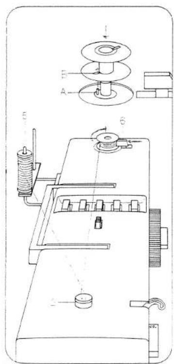
Bobbin winding
Disengage the sewing mechanism. Raise pins 5. Place a bobbin on the bobbin winder so that pin A enters slot B. Place a spool of thread on one of the spool pins. Pass the thread around thread retainer stud 2, wind it around the bobbin a few times, and push lever 6 against the bobbin. The bobbin winder stops automatically when the bobbin is full. Re-engage the sewing mechanism.
Inserting the bobbin
Insert the filled bobbin into the bobbin case so that the thread unreels toward the back (A). Then draw the thread into slot B and under the spring into eye C.
Inserting the bobbin case
Lift latch K and push the bobbin case onto stud B, making sure slot A points upwards. Release the latch and lightly press against the bobbin case to make sure it has snapped into place.
Upper threading
Pull the thread from the spool and draw it into slot A, guide B and take-up lever 1. Then pull it into guides C and D.
text_image
Technical diagram of a mechanical device with labeled components and assembly lines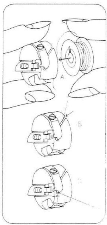
natural_image
Technical line drawing of mechanical components with exploded views (no text or symbols)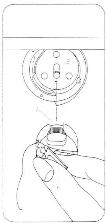
natural_image
Line drawing of a hand using a tool to adjust or install a mechanical component, with no visible text or symbols.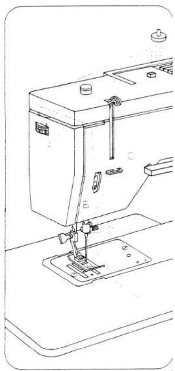
natural_image
Line drawing of a sewing machine with base and clasp mechanism (no text or symbols)Threading the needle 1196-1199
Pull the thread through the needle eye from front to back.
Drawing up the bobbin thread
Hold the needle thread a little taut. Turn balance wheel 7 toward you until the needle moves down and up again and the take-up lever is up. Pull the bobbin thread out of the needle hole and lay both threads toward the left and back under the sewing foot.
Attaching the work support, Model 1196/1197
1196: Turn over the foot control receptacle and attach it (A).
1197: Incline the workplate and push it over the free arm (B) until its guide pins enter the two holes, then lower it.
Attaching the work support, Model 1199/1209
Turn over the foot control receptacle and push it over the free arm as far as it will go

natural_image
Line drawing of a sewing machine needle and screw base assembly (no text or symbols)8

natural_image
Line drawing of a sewing machine needle and screw base (no text or symbols)
natural_image
Line drawing of a sewing machine with a box and clamped mechanism (no text or symbols)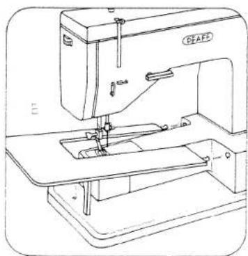
natural_image
Line drawing of a sewing machine (no text or symbols visible)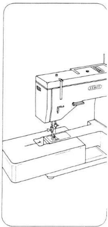
natural_image
Line drawing of a sewing machine with needle and base (no text or symbols)9
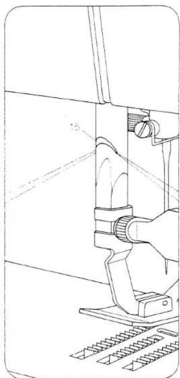
Thread cutter, Models 1196/1199 There is a sharp-edged slot on the back of the presser bar which serves as a thread cutter. Raise the sewing foot. Pull the work back out of the machine. Place the threads in the thread cutter slot and pull them downwards to cut them.
Thread cutter, Model 1209 The thread cutter is located at the back of dual feed 15. Raise the sewing foot. Pull the work back out of the machine. Place the threads over thread cutter 22 and pull them downwards to cut them.
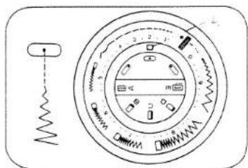
Ultra-Matic stitch selector (9) Turn the outer ring until the symbol of the straight or zigzag stitch desired is positioned above mark A.
Straight stitch Straight stitches are located in the range from 0 to 4.
Zigzag stitch Setting mark = A Zigzag stitches are sewn in the ranges marked 5, 6, 7, 8 and 9. At the right of this range, 5 to 8, the stitches are close together; toward the left, the zigzag stitches become increasingly longer. In ranges 4 and 5 a long, narrow zigzag stitch is made.
natural_image
Technical line drawing of a mechanical assembly with a hand operating a tool (no text or symbols present)10
natural_image
Technical line drawing of a mechanical linkage assembly (no text or symbols)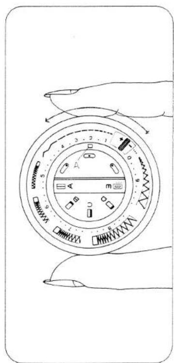
text_image
Diagram of a hand holding a circular device with labeled parts and directional arrows indicating rotation or movement.
text_image
Diagram of a circular device with labeled components and control buttons, likely for industrial or mechanical assembly.11
Needle position
The needle can be set to different positions in the needle hole.
Turn knob 10 until the symbol of the needle position desired is positioned below mark A.
◦ = central needle position (normal)
◦ = right needle position
= left needle position
Reverse sewing and dropping the feed dog
Reverse-feed control 17 has the following positions:
A = Normal position
B = As long as the control is depressed, the machine sews backwards.
C = Vertical position. The machine sews permanently in reverse.
D = The feed dog is dropped (for embroidering, darning, etc.).
Presser bar lifter
Lever 18 has two positions:
A = Sewing foot raised. (Before you remove the work, turn the balance wheel toward you to raise the needle and take-up lever 1.)
B = The sewing foot is lowered for sewing.
Dual feed, Model 1209
This additional feed prevents one ply from creeping ahead of the other. To engage, push dual feed 15 down until it snaps into place. To disengage, push it down slightly, then pull it out.
text_image
Technical diagram of a circular device with labeled components and a spring symbol, likely for measurement or control design.
natural_image
Diagram showing two hand positions on a surface with a magnified view of the object (no text or symbols)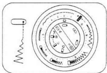
text_image
Diagram of a mechanical device with labeled parts and a spring mechanism indicator
natural_image
Simple line drawing of a vertical cylindrical object with an arrow indicating rotation, no text or symbols present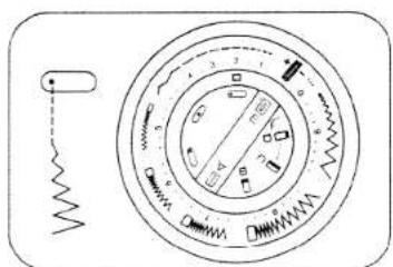
natural_image
Circular mechanical component diagram with springs and a spring, no visible text or symbols
natural_image
Simple line drawing of a rectangular object with a curved arrow and label '第' (no text or symbols on the object itself)
text_image
PEAFF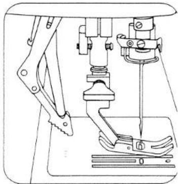
natural_image
Technical line drawing of a sewing machine tool (no text or symbols)
text_image
PFAF
natural_image
Technical line drawing of a sewing machine needle and base mechanism (no text or symbols)Upper tension (16)
A = Setting mark. The normal tension setting is in the green range between 3 and 5. The higher the number, the tighter the tension.
Lower tension
B = Regulating screw. Turn it left for a looser tension, or right for a tighter tension.
C = Both tensions are correct.
= Upper tension too loose or lower tension too tight.
E = Lower tension too loose or upper tension too tight.

text_image
7 6 5
natural_image
Technical line drawing of a mechanical component with no visible text or symbols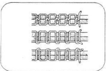
natural_image
Pure electrical circuit lines without any symbols14
The correct lower tension
Let the bobbin case with a full bobbin hang down freely by the thread. It must not slide down by its own weight, but should gradually move downwards when you jerk your hand upwards lightly.
natural_image
Line drawing of a hand holding a small mechanical component, with no visible text or symbolsChanging the needle
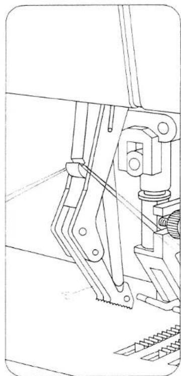
Raise the needle bar. Then hold the needle, loosen screw A and pull the needle out downwards. Insert a new System 130/705 H needle (with the flat side of its shank facing toward the back) and push it up as far as it will go. Then tighten screw A.
Changing the sewing foot
Raise the needle bar. Loosen screw A until the sewing foot can be removed by pulling it forwards, sideways or backwards. Attach the sewing foot and tighten screw A.

natural_image
Technical line drawing of a mechanical device with motion indicators (no text or symbols)
natural_image
Technical line drawing of a sewing machine needle and base mount (no text or symbols)15
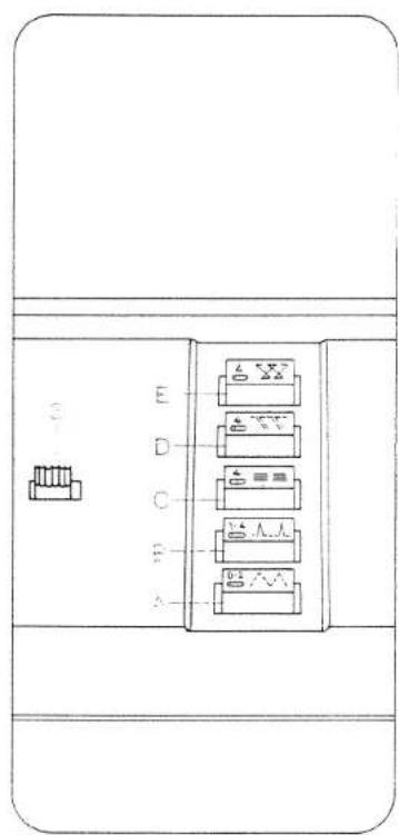
Utility stitches
A Elastic stitch
B Blindstitch
C Elastic triple straight stitch
D Overlock stitch
E Cross stitch
3 Eraser button for releasing the pushed buttons.
Utility-stitch setting
The setting of Ultra-Matic stitch selector 9/10 which is required for a specific utility stitch is indicated on the buttons. Setting:
A = Push button
B = Turn Ultra-Matic stitch selector
Utility-stitch combinations
Pushing two buttons simultaneously produces new utility-stitch patterns.
I Honeycomb stitch
Setting: buttons A+C, straight stitch 4, left needle position.
II Pullover stitch
Setting: buttons B+C, straight stitch 4, left needle position.
III Super stretch stitch
Setting: buttons C+D, straight stitch 4, left needle position, raise reverse-feed control 17.
IV E stitch
Setting: buttons B+C, straight stitch O, left needle position, turn control 17 to vertical position.
V Jersey stitch
Setting: buttons B+D, straight stitch 2, left needle position.
Table of stitches (Supplement)
All stitches, including the utility-stitch combinations, are shown in the Table of Stitches.
text_image
A B C D E16

text_image
A 1-4 1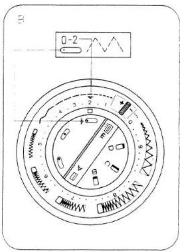
text_image
0-2 4 3 2 1 5 m 6 7 W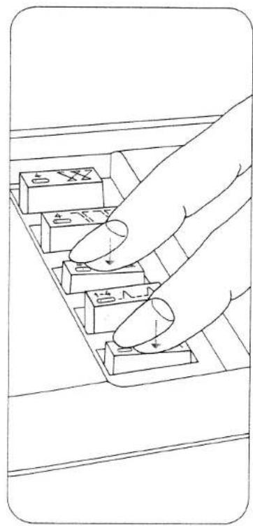
text_image
Diagram showing a hand pressing down on a keyboard with labeled keys and arrows indicating press or function.
text_image
XXXXXX = 0.2 ∧ ∧ + 4 ≡ ≡ △△▽ = 1.4 ∧ ∧ + 4 ≡ ≡ XXXXXX = 4 ∧ ∧ + 4 ≡ ≡ ⊥⊥⊥ = 1.4 ∧ ∧ + 4 ≡ ≡ △△∧ = 1.4 ∧ ∧ + 4 ∧ ∧17
jewing buttonholes
attach buttonhole foot. Release the push buttons. Turn control 9 to + and control 10 to that buttonhole symbol A is positioned below the setting mark. Regulate the stitch density by turning control 9 in the buttonhole range from + to -. Insert a filler cord, is shown in the drawing.
A Sew first buttonhole seam. Turn the balance wheel toward you to raise the needle.
B Turn control to symbol B. Sew 4-6 bartacking stitches, raise the needle.
C Turn control to symbol C. Sew in reverse until the second seam is the same length as the first. Raise the needle.
D Turn control to symbol D. Sew 4-6 bartacking stitches. Raise the needle.
E Turn control to symbol E. Sew a few tying stitches. Turn the balance wheel toward you to bring the take-up lever to its highest point. Remove the material. Pull the filler thread taut and trim both ends.
F Cut buttonhole open.

natural_image
Technical line drawings of a washing machine head and side panel (no text or symbols)18

text_image
Technical diagram showing a dial and thermometer with labeled parts and a close-up of the thermometer.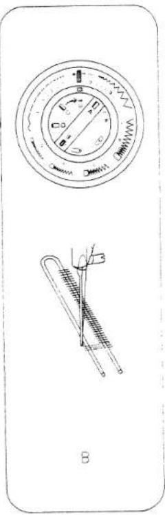
text_image
Technical diagram showing a circular dial with measurement markings and a thermometer illustration.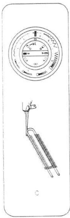
natural_image
Illustration of a washing machine with a circular dial and a thermometer (no text or symbols)
text_image
Technical diagram showing a dial indicator and a spring scale with measurement markings
text_image
Technical diagram showing three mechanical components: dial, measuring tool, and measuring tool with a handle.19
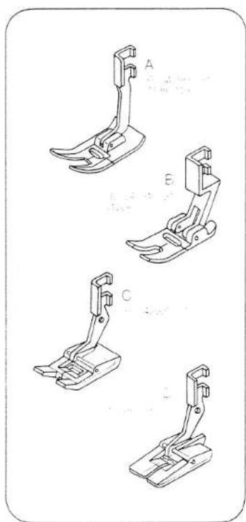
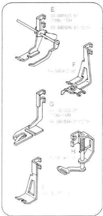
Sewing feet
A Normal sewing foot, Models 1196–1199
B Normal sewing foot, Model 1209; for all sewing operations requiring no special sewing foot.
C Clear-view sewing foot; for ornamental sewing and sewing on buttons.
D Buttonhole foot
E Zipper or edge-stitching foot with edge guide
F Blindstitch foot
G Hemmer foot
H Darning foot; for embroidering and darning.
1 Cording foot; for single-needle cording and appliquing.
natural_image
Four technical line drawings of a sewing machine foot (no text or symbols)20
text_image
E 05-040926-8" (1196-1384) 95-040976-81-4219 F 04-040917-82 G 05-040935-8" (1196-1189) 40-040934-87-4219 I 05-040926-8" (1196-1189)Special accessories
The special accessories listed below are intended for special sewing jobs. They can be obtained from your Pfaff dealer.
| Accessory | Ordering No | Sewing Operation |
| Cording set | 93-107 560-91 | For cording work(needle size 80,for fine cordingneedle size 70) |
| Cording foot. 3 grooves(twin needle with 2.5 or 3.0 mm needle gauge) | 93-040 948-31 | |
| Cording foot. 5 grooves(twin needle with 1.8-, 2.0- or 2.5- mm needle gauge) | 93-040 950-31 | |
| Cording foot. 7 grooves(twin needle with 1.4-, 1.6 or 1.8- mm needle gauge) | 93-040 952-31 | |
| Fringe sewing foot | 93-040 943-31 | For sewing fringes andfor basting |
| Straight-stitch foot | 98-074 005-00 | For topstitching andsewing very delicateand soft fabrics(silk jersey, etc.) |
| Needle plate with round needlehole for free-arm models | 93-040 940-35 | |
| Needle plate with round needlehole for flatbed models | 93-040 939-35 | |
| Edge guide (fastening screw 93-040 959-25) | 91-053 077-25 | For edge stitching |
| Zipper foot | 98-501 000-27 | For inserting zippers |
| Feiling foot | 93-040 938-31 | For felled seams |
| Zigzag shirring foot | 93-847 520-06 | For shirring valances |
| Eyeletting plate | 93-040 946-45 | For eyeletting |
| Hemmer foot (shell-edge) 2.0 mm | 93-847 546-00 | For hemming edges withzigzag stitches |
| Hemmer foot (rolled edge) 1.0 mm | 93-847 547-00 | |
| Bias binder | 98-055 622-00 | For binding edgeswith bias tape |
| Zigzag Teflon foot(coated sole) | 93-040 955-91 | For sewing plastic materials |
| Roller foot | 93-100 912-21 | For sewing coatedsynthetic materials |
| Spool holder | 93-040 584-45 | For sewing with 3 spoolsof thread |
Changing the light bulb
Push the light bulb up, turn it toward A and pull it out. Insert the new light bulb so that its pins enter slots C. Push it up and turn it toward B.
Cleaning and oiling
1196: Remove cover 15. Pull needle plate forward and take it out.
1197-1209: Take out the screws and remove the needle plate. Open cover 24. Remove the bobbin case. Clean the parts in the vicinity of the sewing hook and the feed dog with a soft brush.
Do not oil the machine because it is maintenance-free, but now and then put a drop of oil into the hook raceway.
Threading the needle 1209
Turn the balance wheel toward you to raise the needle and take-up lever 1 (see drawing).
Push control 25 down all the way.
Draw the thread under fingers A and B, at the same time releasing control 25 and the thread. The thread is then pulled through the needle eye.

text_image
Technical diagram showing a hand holding a bottle with labeled parts A, B, and C, illustrating a mechanical or electrical assembly.22

text_image
1196 1197-1209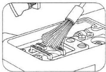
natural_image
Line drawing of a cable connector being inserted into a device casing (no text or symbols)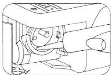
natural_image
Technical line drawing of a mechanical device with no visible text or symbols
text_image
Technical diagram showing a sewing machine with labeled parts and hand positions for assembly or repair.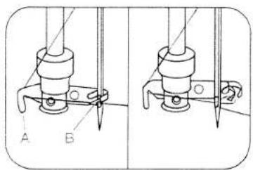
text_image
Technical diagram showing two mechanical assembly states labeled A and B, with tool tips and pivot points marked.Trouble shooting
| Cause: | Remedy: |
| 1. Machine skips stitches | |
| Needle not inserted correctly. | Push needle up as far as it will go, its flat shank side facing toward the back. |
| Wrong needle used. | Insert system 130/705 H needle. |
| Needle bent or blunt. | Insert new needle. |
| Machine threaded improperly. | Check threading. |
| Needle too thin for thread used. | Select needle according to Needle and Thread Chart. |
| 2. Needle thread breaks | |
| For any of the above reasons. | See par. 1 above. |
| Thread tension too strong. | Regulate thread tensions. |
| Poor-quality or knotty thread used,or thread that has become too dry byexcessive storage. | Use only good-quality thread. |
| 3. Needle breaks | |
| Needle not pushed up as far as it will go. | Insert new needle and push it up as far as it will go. |
| Needle bent. | Insert new needle. |
| Needle too thin or too thick. | Note Needle and Thread Chart. |
| Needle bent and strikes needle platebecause work is pushed or pulled. | Let machine feed the work alone.Only guide the material lightly. |
| Bobbin case improperly inserted. | When inserting the bobbin case, press against it until it snaps into place. |
| Cause: | Remedy: |
| 4. Seam is not uniform | |
| Tension out of adjustment. | Check upper and lower tensions. |
| Thread too thick, knotty or hard. | Use first-class thread only. |
| Bobbin thread wound unevenly. | During bobbin winding, do not hold thread in hand, but pass it through thread retainer stud. |
| Kinks appear on top and bottom of material. | Thread machine properly and check both tensions. |
| 5. Machine feeds irregularly or not at all | |
| Lint has accumulated between tooth rows of feed dog. | Remove needle plate and clean out lint. |
| Feed dog dropped. (Reverse-feed control is at left.) | Flick reverse-feed control to the right. |
| 6. Machine works heavily | |
| Thread ends in hook raceway. | Remove thread ends and put a drop of oil into hook raceway. |