
KS-AX3104 - Car amplifier JVC - Free user manual and instructions
Find the device manual for free KS-AX3104 JVC in PDF.

| Product Type | 4-Channel Car Amplifier |
| Brand | JVC |
| Model | KS-AX3104 |
| Output Power (Normal) | 60 W RMS × 4 (4 Ω, ≤1% THD+N) 90 W RMS × 4 (2 Ω, ≤1% THD+N) |
| Output Power (Bridged) | 150 W RMS × 2 (4 Ω, ≤1% THD+N) |
| Max Power | 800 W (400 W × 2) |
| Load Impedance (Normal) | 4 Ω (2 to 8 Ω admissible) |
| Load Impedance (Bridged) | 4 Ω (4 to 8 Ω admissible) |
| Frequency Response | 5 Hz – 50 000 Hz (+0 dB, -3 dB) |
| Input Sensitivity / Impedance | 2 V / 21 kΩ (0.3 to 6 V variable) |
| Distortion | <0.04% (at 1 kHz) |
| Signal-to-Noise Ratio | 76 dBA (ref. 1 W into 4 Ω) |
| Power Supply | DC 14.4 V (11 to 16 V admissible) Negative ground |
| Dimensions (W × H × D) | 335 × 51 × 212 mm |
| Weight | approx. 2.43 kg |
| Filters | Low-pass filter (LPF) 50–200 Hz High-pass filter (HPF) 150 Hz Bypass possible |
| Bass Control | Bass Boost: 0 to +18 dB at 45 Hz |
| Inputs | Line RCA inputs (2 channels) High-level input via speaker input connector |
| Protections | Built-in fuse, short-circuit protection |
| Supplied Accessories | Speaker input connector 3P × 2, mounting screws φ4 × 20 mm × 4 |
| Maintenance | Dust regularly to ensure heat dissipation |
| Safety | Do not disassemble, do not expose to moisture, disconnect battery before connection |
Frequently Asked Questions - KS-AX3104 JVC
User questions about KS-AX3104 JVC
0 question about this device. Answer the ones you know or ask your own.
Ask a new question about this device
Download the instructions for your Car amplifier in PDF format for free! Find your manual KS-AX3104 - JVC and take your electronic device back in hand. On this page are published all the documents necessary for the use of your device. KS-AX3104 by JVC.
USER MANUAL KS-AX3104 JVC
Thank you for purchasing a JVC product.
If you have any questions or require information regarding installation kits, consult your "JVC IN
CAR ENTERTAINMENT" or a company supplying the kits.
For safety.
- Stop the car before performing any complicated operations.
CAUTIONS AND NOTES
This unit is designed to operate on 12 V DC, NEGATIVE ground electrical systems.
JVC recommends consulting a qualified technician for installation.
- This unit uses BTL (Balanced Transformerless) amplifier circuitry, i.e., floating ground system, so comply with the following:
- Do not connect the “ ” terminals of the speakers to each other.
- Do not connect the “ ” terminals of the speakers to the metal body or chassis.
- Cover the unused leads with insulating tape to prevent them from short circuiting.
- When an extension lead is used, it should be as thick and short as possible; connect it firmly with insulating tape.
- Be sure to leave an appropriate space between the antenna (aerial) and the wires of this unit.
- If the fuse blows, first make sure the wires aren't touching to cause a short circuit then replace the old fuse with one with the same rating.
- Do not let pebbles, sand or metallic objects get inside the unit.
- To keep the heat dissipation mechanism running effectively, wipe the accumulated dust off periodically.
- Listening to the tape, radio, CD or digital audio player, etc. with the volume set at a high level for a long period of time will exhaust the battery, while the engine is turned off or while the engine is idling.
- This unit becomes very hot. Be careful not to touch the unit not only when using but after using. DO NOT disassemble the unit since there are no user serviceable parts inside.
INSTALLATION
The following illustration shows a typical installation. However, you should make adjustments corresponding to your specific car.
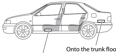
A Location of the unit
Under the front seat
- Mount this unit on a firm surface, such as in the trunk or under the front seat.
- Since heat is generated in the unit, do not mount it near inflammable objects. In addition, mount it in an area that will not prevent the unit from dissipating the heat.
- Do not mount the unit in the places subject to heat: near a radiator, in a glove compartment or in insulated areas such as under a car mat that will prevent the unit from dissipating heat.
- When mounting the unit under the front seat, make sure that adjusting the seat position will not catch any wire of the unit.
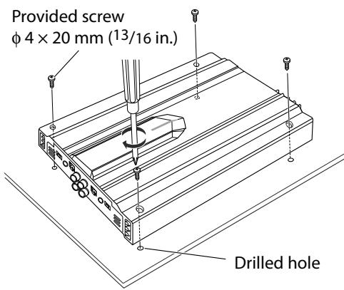
B Install the unit
- When mounting this unit, be sure to use the provided screws.
- If any other screws are used, there is a risk of loosening the unit or damaging the parts under the car floor.
- Before drilling holes in the trunk to install the unit, make sure that there is a sufficient space under the trunk so that you do not drill holes in the fuel tank, etc.
SAFETY INSTRUCTIONS
"SOME DOS AND DON'TS ON THE SAFE USE OF EQUIPMENT"
This equipment has been designed and manufactured to meet international safety standards but, like any electrical equipment, care must be taken if you are to obtain the best results and safety is to be assured.
DO read the operating instructions before you attempt to use the equipment.
DO ensure that all electrical connections (including the mains plug, extension leads and interconnections between pieces of equipment) are properly made and in accordance with the manufacturer's instructions. Switch off and withdraw the mains plug when making or changing connections.
DO consult your dealer if you are ever in doubt about the installation, operation or safety of your equipment.
DO be careful with glass panels or doors on equipment.
DONT continue to operate the equipment if you are in any doubt about it working normally, or if it is damaged in any way-switch off, withdraw the mains plug and consult your dealer.
DONT remove any fixed cover as this may expose dangerous voltages.
DON'T leave equipment switched on when it is unattended unless it is specifically stated that it is designed for unattended operation or has a standby mode. Switch off using the switch on the equipment and make sure that your family know how to do this. Special arrangements may need to be made for infirm or handicapped people.
DON'T use equipment such as personal stereos or radios so that you are distracted from the requirements of traffic safety. It is illegal to watch television whilst driving.
DONT listen to headphones at high volume as such use can permanently damage your hearing.
DONT obstruct the ventilation of the equipment, for example with curtains or soft furnishings. Overheating will cause damage and shorten the life of the equipment.
DON'T use makeshift stands and NEVER fix legs with wood screws–to ensure complete safety always fit the
manufacturer's approved stand or legs with the fixings provided according to the instructions.
DON'T allow electrical equipment to be exposed to rain or moisture.
ABOVE ALL
NEVER let anyone, especially children, push anything into holes, slots or any other opening in the case — this could result in a fatal electrical shock.
NEVER guess or take chances with electrical equipment of any kind-it is better to be safe than sorry!
E43486-340B
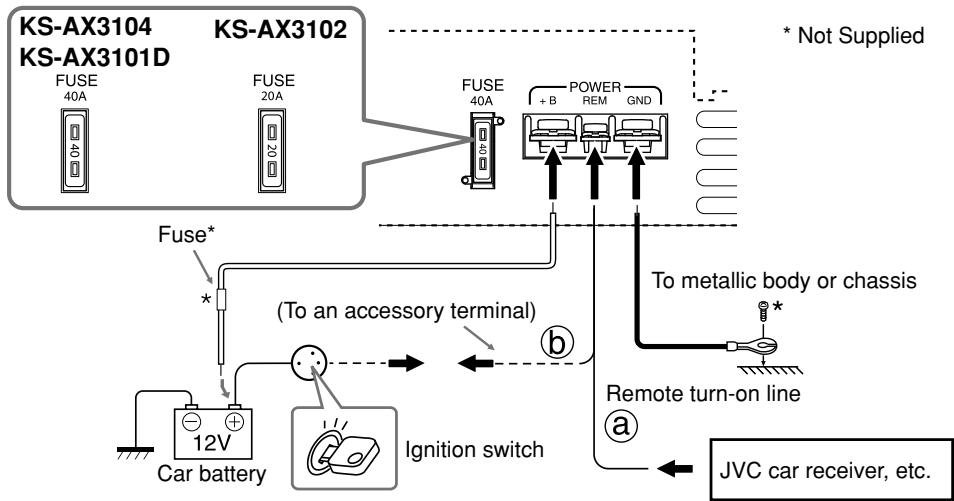
POWER SUPPLY
Caution
To prevent short circuits while making connections, keep the battery's negative terminal disconnected.
- When using a power cord (purchased separately), be sure to place the fuse near the battery as shown.
- Connect the lead wire (power cord) through which power is supplied directly to the battery's "⊕" terminal only after all the other connections have been made.
The proper lead wire connected to each POWER terminal is as follows.
· + B and GND: AWG 8 to AWG 4 (The cross section is about 8mm^2 to 21mm^2 .)
- REM: AWG 18 to AWG 8 (The cross section is about 0.8mm^2 to 8mm^2 .)
@ When you use JVC car receiver with a remote lead, connect to the REM terminal on this unit.
⑥ When you connect a unit without a remote lead, connect to the accessory circuit of the car which is activated by the ignition switch. In this case, noise may occur when the car receiver is turned on or off. To avoid this noise, do not turn on or off the car receiver itself. You can turn on or off the car receiver along with the on/off operation of the ignition switch.
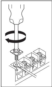
TERMINAL CONNECTIONS
When making terminal connections, properly fix each terminal with the provided screw by turning it as illustrated.
- Use ring terminals (not provided) for secure connection.
Notes
- Make sure the screw is fixed in place to prevent disconnections.
- Avoid over-tightening as it may cause the damage to the screw or its head slot.
SPEAKER SYSTEMS
Notes
- Be sure not to connect the “ ” terminals of the speakers to a common point.
- If the same lead is used for both left/right or front/rear speaker wirings, this unit cannot be used.
Always use the independent leads for each speaker. In this case, redo the wirings. - Use the speakers with an impedance of 2 to 8 (4 to 8 : when used in Bridge Mode).
- Use the speakers which have sufficient capacity to the unit.
The proper lead connected to each SPEAKER OUTPUT terminal is as follows.
KS-AX3104/KS-AX3102: AWG 18 to AWG 12 (The cross section is about 0.8mm^2 to 3.3mm^2 ).
KS-AX3101D: AWG 18 to AWG 8 (The cross section is about 0.8mm^2 to 8mm^2 ).
Dear Customer,
This apparatus is in conformance with the valid European directives and standards regarding electromagnetic compatibility and electrical safety.
European representative of Victor Company of Japan, Limited is:
JVC Technical Services Europe GmbH
Postfach 10 05 04
61145 Friedberg
Germany
Information for Users on Disposal of Old Equipment and Batteries

Products

Battery
[European Union only] These symbols indicate that the product and the battery with this symbol should not be disposed as general household waste at its end-of-life. If you wish to dispose of this product and the battery, please do so in accordance with applicable national legislation or other rules in your country and municipality. By disposing of this product correctly, you will help to conserve natural resources and will help prevent potential negative effects on the environment and human
health.
Notice:
The sign Pb below the symbol for batteries indicates that this battery contains lead.
Connection varies depending on the number of the speakers used in your car. Select the appropriate connection referring to the following diagrams.
Notes
- Securely connect all the parts. If the connections are loose, due to contact resistance etc., heat will break out and may cause an accident.
- Run the connection leads under the car mats to prevent accidental disconnections.
A When your receiver is equipped with line output.
8 When your receiver is NOT equipped with line output.
KS-AX3102 KS-AX3101D
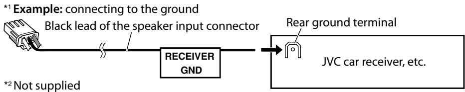
- Connect each lead of the speaker input connector to a speaker positive lead or chassis*1 of the receiver.
- Cover the terminals of unused speaker negative leads of the receiver with insulating tape to prevent short circuits.
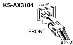
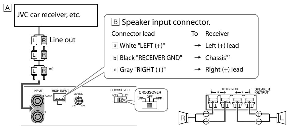
KS-AX3104
4-speaker system—Normal Mode
- Use the speakers with an impedance of 2 to 8 .
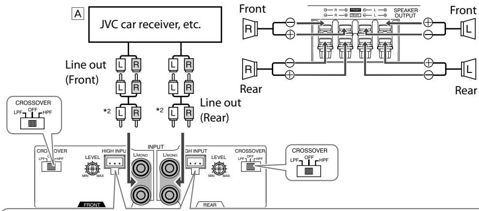
Speaker input connector.
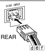
Connector lead To Receiver Connector lead To Receiver
a White "FRONT LEFT (+)" Front left (+) lead d Green "REAR LEFT (+)" Rear left (+) lead
Black "RECEIVER GND" Chassis*1 Black "RECEIVER GND" Chassis*1
Gray "FRONT RIGHT (+)" Front right (+) lead Purple "REAR RIGHT (+)" Rear right (+) lead
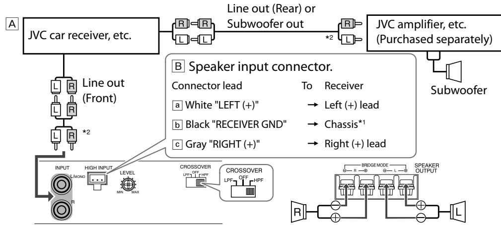
2-speaker system plus subwoofer—Bridge Mode
- Use the speakers with an impedance of 2 to 8 .
- Use the subwoofer with an impedance of 4 to 8 .
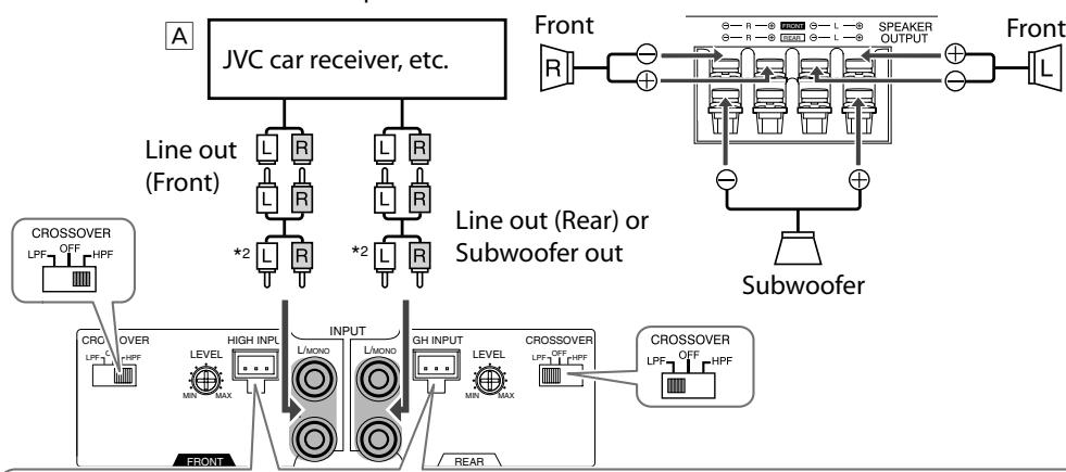
Speaker input connector.
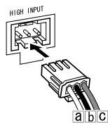
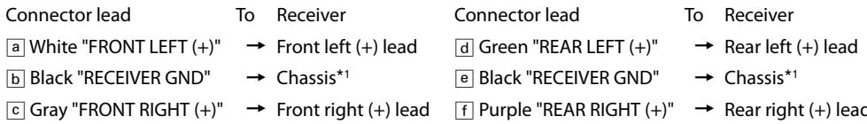
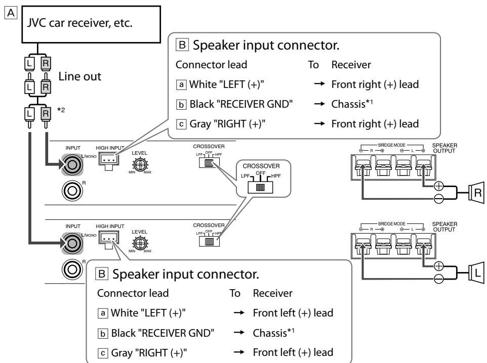
2-speaker system—Bridge Mode
- Use the speakers with an impedance of 4 to 8 .
- Be sure to connect the line output from the receiver to the left (L) jack on this unit.
Speaker input connector.
Connector lead To Receiver Connector lead To Receiver
White"FRONTLEFT (+) " Frontleft (+) lead Green"REARLEFT (+) " Frontright (+) lead
Black "RECEIVER GND" Chassis*1 Black "RECEIVER GND" Chassis*1
Gray"FRONTRIGHT (+) " Frontleft (+) lead Purple"REARRIGHT (+) " Frontright (+) lead
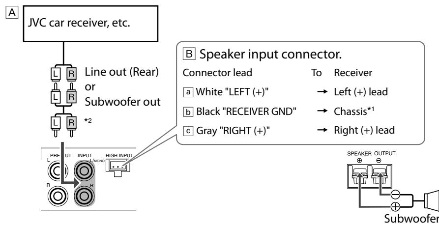
KS-AX3102
2-speaker system—Normal Mode
- Use the speakers with an impedance of 2 to 8 .
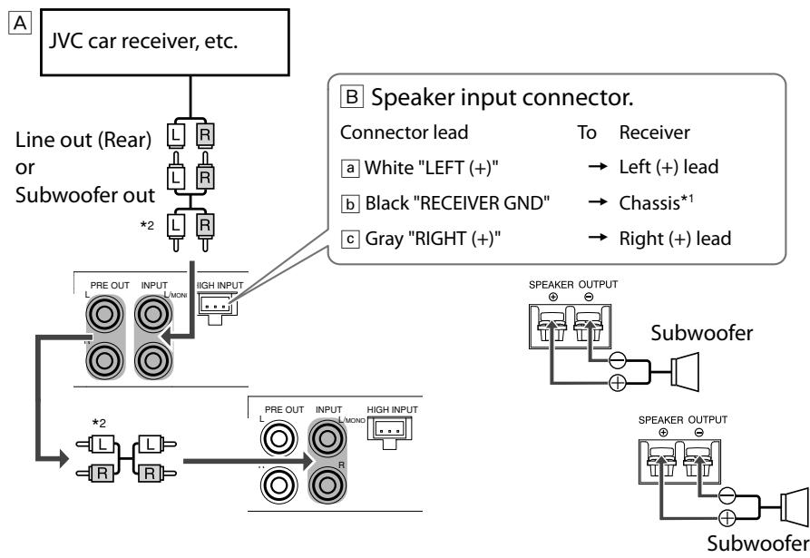
2-speaker system plus subwoofer
- Use the speakers with an impedance of 2 to 8 .
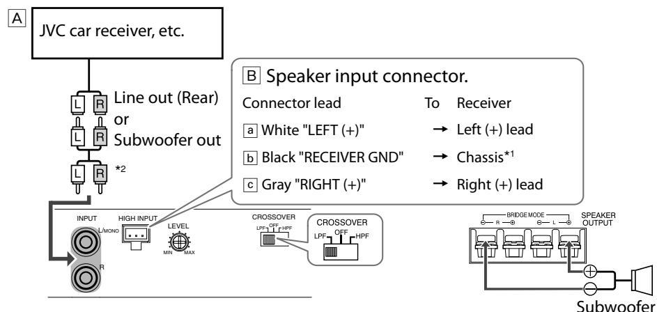
Subwoofer system—Bridge Mode
- Use the speakers with an impedance of 4 to 8 .
2-speaker system (2 amplifiers)—Bridge Mode
- Use the speakers with an impedance of 4 to 8 .
- Be sure to connect the line output from the receiver to the left (L) jack on this unit.
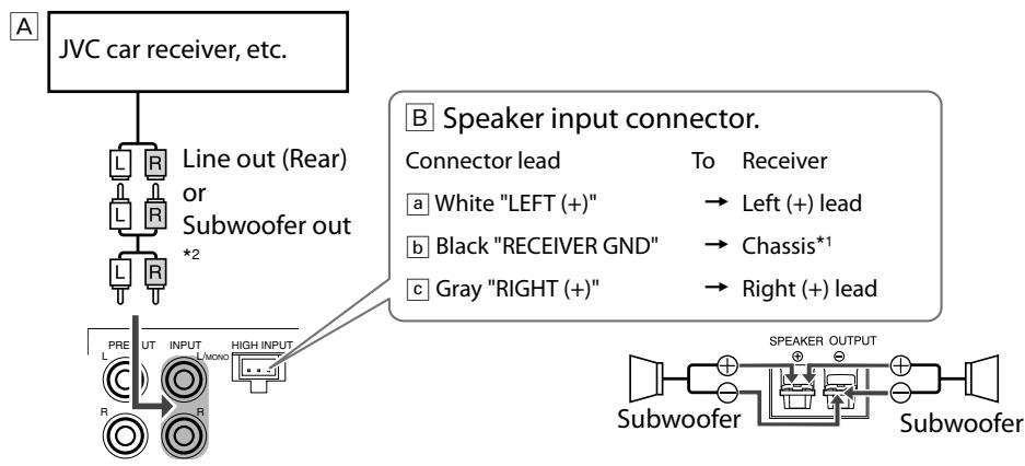
KS-AX3101D
Subwoofer system
- Use the speakers with an impedance of 2 to 8 .
KS-AX3101D
2-Subwoofer system (2 amplifiers)
- Use the speakers with an impedance of 2 to 8 .
- Incoming signals from INPUT jacks are emitted through the PRE OUT jacks.
2-Subwoofer system
- Use the speakers with an impedance of 4 to 8 .
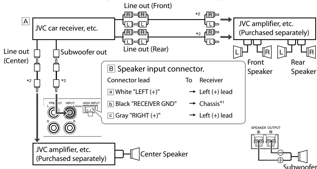
5-speaker system plus subwoofer—5.1-channel (3 amplifiers)
- Use the speakers with an impedance of 2 to 8 .
- Be sure to connect the line output from the receiver to the left (L) jack on this unit.
CONTROLS
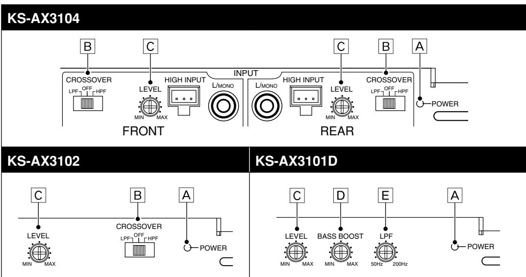
A POWER indicator
The green lamp lights while the unit is turned on.
B CROSSOVER filter switch
OFF: Normally set to this position. The switch is preset to this position when the unit is shipped.
LPF: Set to this position when you want to turn on the LPF (Low-Pass Filter) switch. The LowPass Filter transmits frequencies lower than 80Hz .
HPF: Set to this position when you want to turn on the HPF (High-Pass Filter) switch. The High-Pass Filter transmits frequencies higher than 150 Hz.
Input LEVEL controller
The input level can be adjusted with this control when this unit is connected to other source equipment. Adjust the level while listening to the sound. This control is preset to MIN when the unit is shipped.
BASS BOOST controller
Turning this boosts the 45Hz frequency within the range of 0 dB to +18 dB. Adjust the level while listening to the sound. This controller is preset to MIN when the unit is shipped.
LPF (Low-Pass Filter) controller
Adjust the cutoff frequency (the Low-Pass Filter transmits frequencies lower than the cutoff frequency) within the range of 50Hz to 200Hz . Adjust the level while listening to the sound. This controller is preset to 50Hz when the unit is shipped.
TROUBLESHOOTING
The POWER indicator does not light.
- Change the fuses if the current one is blown.
- Connect the ground lead securely to a metal part of the car.
- Turn on the equipment connected to this unit.
- Confirm the battery voltage (11 V to 16 V).
- Use a relay if your system employs too many amplifiers.
- Leave the unit turned off to cool it down if it heats up abnormally.
No sound is heard.
- Confirm the connections for the power supply (see "POWER SUPPLY" on page 1).
- Connect the RCA pin cords to the INPUT jacks, or the speaker input connector to the HIGH INPUT terminal.
- Confirm the speaker wirings and the position of the CROSSOVER filter switch (See "SPEAKER CONNECTIONS" on page 2).
Alternator noise is heard.
- Keep the leads of the POWER terminals away from the RCA pin cords.
- Keep the RCA pin cords away from other electrical cables in the car.
- Connect the ground lead securely to a metal part of the car.
- Make sure the speaker negative leads do not touch the car chassis.
- Connect a bypass capacitor across the accessory switches (horn, fan, etc....).
Noise is made when you connect the unit to an AM (MW/LW) tuner.
- Move all the leads of this unit away from the antenna (aerial) lead.
SPECIFICATIONS
| KS-AX3104 | KS-AX3102 | KS-AX3101D | |
| Power Output • Normal Mode: • Signal-to-Noise Ratio | 60 W RMS × 4 channels at 4 Ω and ≤ 1% THD + N 76 dBA (reference: 1 W into 4 Ω) | 65 W RMS × 2 channels at 4 Ω and ≤ 1% THD + N 76 dBA (reference: 1 W into 4 Ω) | 250 W RMS × 1 channels at 4 Ω and ≤ 1% THD + N 60 dBA (reference: 1 W into 4 Ω) |
| Power Output • Normal Mode: • Bridge Mode: | 90 W RMS × 4 channels at 2 Ω and ≤ 1% THD + N 150 W RMS × 2 channels at 4 Ω and ≤ 1% THD + N | 90 W RMS × 2 channels at 2 Ω and ≤ 1% THD + N 150 W RMS × 1 channels at 4 Ω and ≤ 1% THD + N | 400 W RMS × 1 channels at 2 Ω and ≤ 1% THD + N — |
| Maximum Power Output | 800 W (400 W × 2) | 400 W | 800 W |
| Load Impedance • Normal Mode: • Bridge Mode: | 4 Ω (2 Ω to 8 Ω allowance) 4 Ω (4 Ω to 8 Ω allowance) | 4 Ω (2 Ω to 8 Ω allowance) 4 Ω (4 Ω to 8 Ω allowance) | 4 Ω (2 Ω to 8 Ω allowance) — |
| Frequency Response | 5 Hz to 50,000 Hz (+0 dB, -3 dB) | 5 Hz to 50,000 Hz (+0 dB, -3 dB) | 20 Hz to 200 Hz (+0 dB, -3 dB) |
| Input Sensitivity/Impedance | 2 V/21 kΩ (0.3 V to 6 V, variable) | 2 V/21 kΩ (0.3 V to 6 V, variable) | 2 V/40 kΩ (0.3 V to 6 V, variable) |
| Distortion | Less than 0.04% (at 1 kHz) | Less than 0.04% (at 1 kHz) | Less than 0.08% (at 100 Hz) |
| Power Requirement | DC 14.4 V (11 V to 16 V allowance) | DC 14.4 V (11 V to 16 V allowance) | DC 14.4 V (11 V to 16 V allowance) |
| Grounding system | Negative ground | Negative ground | Negative ground |
| Dimensions (W×H×D) | 335 mm × 51 mm × 212 mm (13-4/16 in. × 2-1/16 in. × 8-6/16 in.) | 202 mm × 51 mm × 212 mm (8 in. × 2-1/16 in. × 8-6/16 in.) | 222 mm × 51 mm × 212 mm (8-12/16 in. × 2-1/16 in. × 8-6/16 in.) |
| Mass (approx.) | 2.43 kg (5.3 lbs) | 1.52 kg (3.4 lbs) | 1.83 kg (4.0 lbs) |
| Accessories | Speaker input connector 3P × 2 Mounting Screw φ4 × 20 mm (13/16 in.) × 4 | Speaker input connector 3P × 1 Mounting Screw φ4 × 20 mm (13/16 in.) × 4 | Speaker input connector 3P × 1 Mounting Screw φ4 × 20 mm (13/16 in.) × 4 |