iQ (2010) - Car TOYOTA - Free user manual and instructions
Find the device manual for free iQ (2010) TOYOTA in PDF.

User questions about iQ (2010) TOYOTA
0 question about this device. Answer the ones you know or ask your own.
Ask a new question about this device
Download the instructions for your Car in PDF format for free! Find your manual iQ (2010) - TOYOTA and take your electronic device back in hand. On this page are published all the documents necessary for the use of your device. iQ (2010) by TOYOTA.
USER MANUAL iQ (2010) TOYOTA
natural_image
Black and white photo of a car's steering wheel and dashboard, showing hands on the steering wheel (no visible text or symbols)Table of Contents
Accessing your vehicle 2 – 3
Steering wheel adjustment 3
Seat and seat belt adjustment 4
Instrument Panel overview 5
Airbag indicators and Audio System 6
Heating, A/C and de-misting 7
Instrument Cluster 8
Multi-information display 9
Lights 10
Wipers 11
Electric windows and windows lock 12
Starting your vehicle 12
Gear change 13
Gear Shift Indicator 14
Fuel tank opening 14
Bonnet opening 15
If you have a flat tyre 15
Eco-Driving 16
Introducing iQ
Thank you for buying an iQ. We trust this Brief Guide will enable you to become familiar with your vehicle's basic operations and assist you in enjoying your vehicle.
This Brief Guide does not replace or substitute the Owner's Manual, which you will find in the vehicle's glove compartment. It is important that you review the full Owner's Manual as well as any further supplementary manuals as this will allow you to familiarise yourself with the operating and safety instructions and to handle the vehicle within its limitations.
Please read all documents in your pack as this will ensure you get maximum performance from your car and learn about related services offered.
Your Centre and everyone at Toyota wish you many years of enjoyable driving in your new iQ.
NB: All information contained in this Brief Guide are current at the time of printing. Toyota reserves the right to make changes at any time without notice.
Accessing Your Vehicle
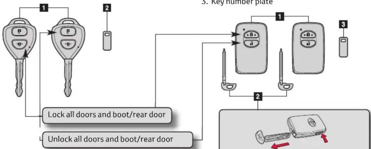
Vehicles without smart entry & start
- Master keys
- Operate the wireless remote control function.
- Key number plate
flowchart
graph TD
    A["Key Number Plate"] --> B["Lock all doors and boot/rear door"]
    A --> C["Unlock all doors and boot/rear door"]
    B --> D["Key Numbers"]
    C --> D
    D --> E["Number 1"]
    D --> F["Number 2"]
    D --> G["Number 3"]
The wireless remote control can be used to lock and unlock your vehicle from the outside.
Vehicles with smart entry & start system
-
Electronic keys
-
Operate smart entry & start system
-
Operate the wireless remote control function
-
Mechanical keys
- Key number plate

flowchart
graph TD
    A["Device 1"] --> B["Device 2"]
    C["Device 3"] --> B
    B --> D["Device 3"]
    style A fill:#f9f,stroke:#333
    style C fill:#f9f,stroke:#333
    style D fill:#ccf,stroke:#333
The Mechanical Key is stored within the Electronic Key
Smart entry & Start system
Unlocking and locking the doors and boot

text_image
Diagram illustrating car door lock operation with hand gesture and control panel, showing hand holding a device and water level indicator.Grip the handle to unlock the doors.
Make sure to touch the sensor on the back of the handle.
Touch the lock sensor to lock the doors.
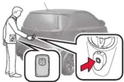
text_image
Diagram showing a person using a car to touch a door panel, with an inset close-up highlighting the door panel and a red arrow indicating action.Press the unlock button to unlock the boot.
Press and hold the button for 1 second to open the back door.
Lock the back door again when you leave the vehicle. The back door will not lock automatically after it has been opened and then closed.
The door and boot cannot be unlocked for 3 seconds after the door or boot is locked. The vehicle can be locked and unlocked using the entry function, wireless remote control, key or door lock switch.
Unlocking and locking the doors for vehicles without Smart entry & Start system

text_image
Diagram showing a mechanical or fluid system with labeled components and directional arrows indicating motion or flow.- Locks all doors.
- Unlocks all doors.
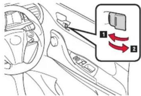
Door lock switch

text_image
Diagram of car interior showing dashboard and steering wheel with labeled parts and directional arrows indicating movement or change.- Unlocks all doors.
- Locks all doors.
Inside lock button
text_image
Diagram of car interior showing dashboard, steering wheel, and directional arrows indicating movement or change in the dashboard.- Locks the door.
- Unlocks the door.
Pulling the door handle can open the driver's door even if the lock button is in the lock position.
If a door is not opened within approximately 30 seconds after the vehicle is unlocked, the security feature automatically locks the vehicle again.
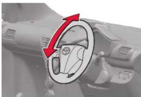
Steering wheel adjustment
The steering wheel can be adjusted to a comfortable position.
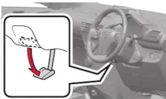
text_image
Diagram showing a car steering wheel with a red arrow indicating the turning point, alongside an inset diagram illustrating the steering wheel's rotation.Hold the steering wheel and press the lever down.
natural_image
Diagram of a car interior showing a steering wheel and dashboard with a red directional arrow indicating rotation (no text or symbols)Adjust the ideal position by moving the steering wheel vertically.
After adjustment, pull the lever up to secure the steering wheel. The steering wheel must not be adjusted while the vehicle is in motion.
Seat and seat belt adjustment
Type A

text_image
Caution - when returning the seatback to upright, take care as it may rebound.- Seat position adjustment lever.
- Seat back angle adjustment lever.
- Seat back angle adjustment lever (passenger's seat only).
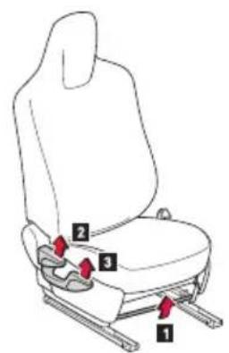
Type B (On some models)
text_image
Diagram of a car seat with numbered labels pointing to different seat positions- Seat position adjustment lever.
- Seat back angle adjustment lever.
- Vertical height adjustment lever.

natural_image
Line drawing of a person sitting in a chair wearing a seatbelt and holding a long object (no text or symbols)Extend the shoulder belt so that it comes fully over the shoulder, but does not come into contact with the neck or slide off the shoulder.
Position the lap belt as low as possible over the hips.
Adjust the position of the seatback. Sit up straight and well back in the seat.
Do not twist the seat belt.
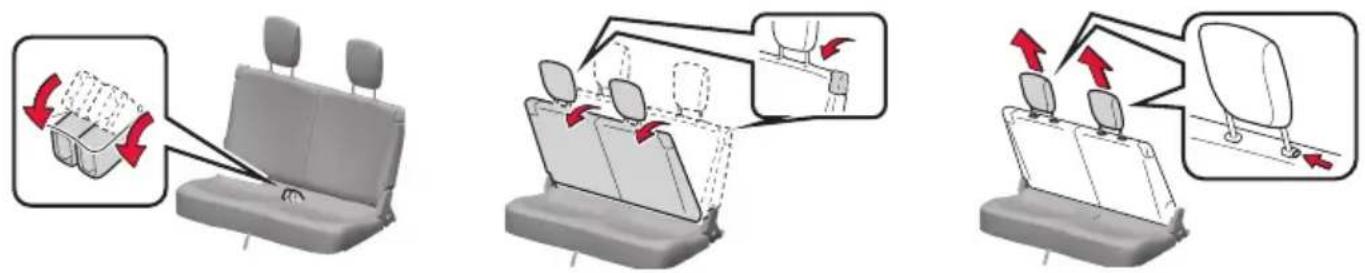
text_image
Diagram illustrating seatbelting instructions with red arrows indicating movement and loading of a seatbelt.Stow the seat belt buckles.
Pull the lock release lever and fold down the seatback until it reaches the position where the head restraints can be removed.
Remove the head restraints by pulling the head restraint up while pushing the lock release button.
Make sure that all occupants are wearing their seat belts before driving the vehicle.
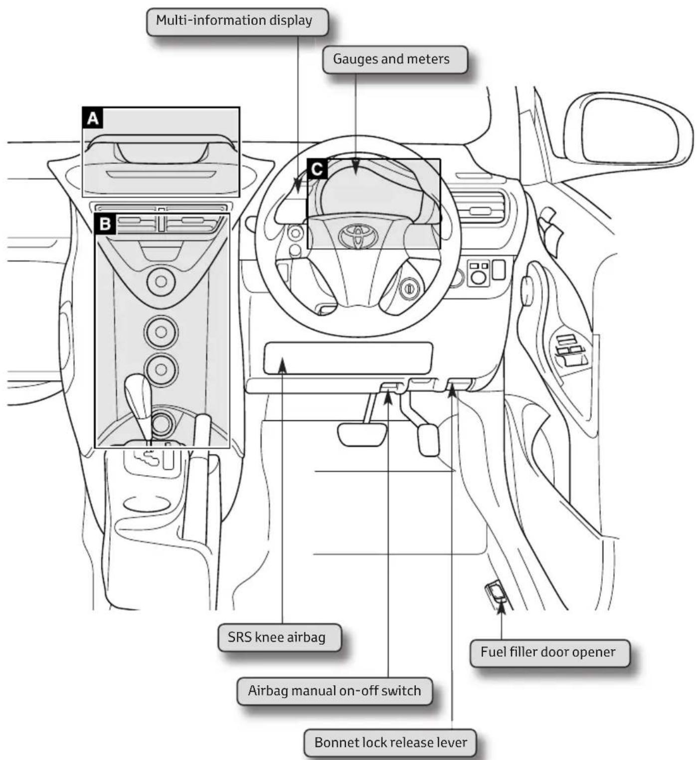
Instrument Panel Overview
text_image
Multi-information display Gauges and meters A B C SRS knee airbag Airbag manual on-off switch Bonnet lock release lever Fuel filler door openerA. Airbag indicators and Audio system
B. Air conditioning system
C. Instrument cluster
Airbag indicators and Audio System
Area Adicated on instrument panel overview (page 5).
Vehicles without audio system Vehicles with audio system

text_image
Passenger airbag indicator Passenger airbag indicator PASSENGER AIR BAG OFF PASSengers Audio systemAudio system
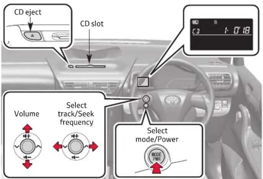
text_image
CD eject CD slot Volume Select track/Seek frequency Select mode/Power MODE PWRFor full explanation, please consult your Owner's Manual, Chapter 3-2
Heating, A/C and de-misting
Area Bdicated on instrument panel overview (page 5).

flowchart
graph TD
    A["Fan speed control dial"] --> B["Air intake selection dial"]
    C["Air outlet selection dial"] --> D["Air conditioning ON/OFF button"]
    E["Temperature control dial"] --> F["Central dial with icon"]
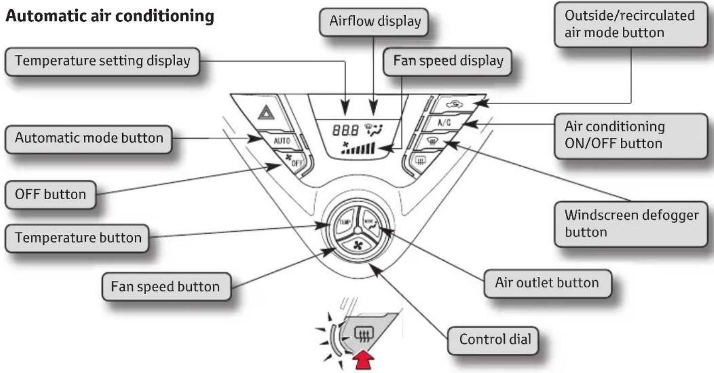
flowchart
graph TD
    A["Automatic air conditioning"] --> B["Temperature setting display"]
    A --> C["Automatic mode button"]
    A --> D["OFF button"]
    A --> E["Temperature button"]
    A --> F["Fan speed button"]
    A --> G["Control dial"]
    A --> H["Air flow display"]
    A --> I["Fan speed display"]
    A --> J["Air conditioning ON/OFF button"]
    A --> K["Air outlet button"]
    A --> L["Outside/recirculated air mode button"]
Rear window and outside rear view mirror defoggers
This feature is used to defog the rear window. Turning it on with also turn the outside rear view mirrors defoggers on*.
With manual air conditioning system : Press the button again to turn it off.
With automatic air conditioning system: The defoggers will automatically turn off after approximately 15 minutes.
*: If equipped.
-
Switch AUTO button off (light is OFF)
-
Switch A/C ON (light is ON)

-
Switch air recirc off (light is OFF)
-
Switch airflow to windscreen (light ON)

Area C dicated on instrument panel overview (page 5).
Vehicles without smart entry and start system
The following gauges, meters and displays illuminate when the engine switch is in the "ON" position.
Vehicles with smart entry & start system
The following gauges, meters and displays illuminate when the “ENGINE START STOP” switch is in the IGNITION ON mode.
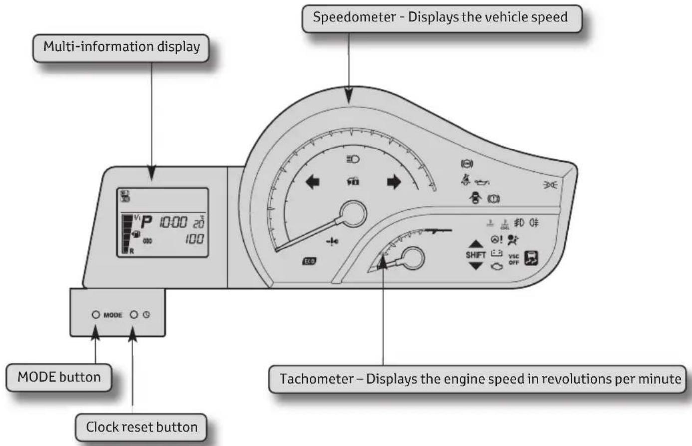
text_image
Multi-information display Speedometer - Displays the vehicle speed MODE button Clock reset button MODE button Tachometer - Displays the engine speed in revolutions per minuteWhen disconnecting and reconnecting battery terminals the following information will be reset: Clock, Trip meter, Average fuel consumption after refueling and Average vehicle speed
Setting the clock
- Press and hold the clock rest button to enter the adjustment mode for the clock.
- Press the clock reset button to adjust the minutes. After adjusting the minutes, wait 5 seconds to allow the minutes to be automatically input.
- Press the clock reset button to adjust the hours. After adjusting the hours, wait 5 seconds to allow the hours to be automatically input and the mode to return to normal.

text_image
Diagram of a speedometer with labeled control panel and indicator lights, showing measurement scale and directional arrow.Main Indicators
The indicators inform the driver of the operating state of the vehicle's main systems.


Turn signal indicator Headlight high beam

Side / Headlight indicator

Front fog light indicator

Rear fog light indicator
Main Warning Lights
Warning lights inform the driver of malfunctions in any of the vehicle's systems.


These lights turn on when the engine switch is turned to the ON position (vehicles without smart entry & start system) or the “ENGINE START STOP” switch is turned to IGNITION ON mode (vehicles with smart entry & start system) to indicate that a system check is being performed. They will turn off after the engine is started, or after a few seconds. There may be a malfunction in a system if a light does not come on, or if the lights do not turn off. Have the vehicle inspected by any authorised Toyota Centre or authorised repairer, or another duly qualified and equipped professional for details.
For details, see Chapter 2-2 of Owner's Manual.
Multi-information display
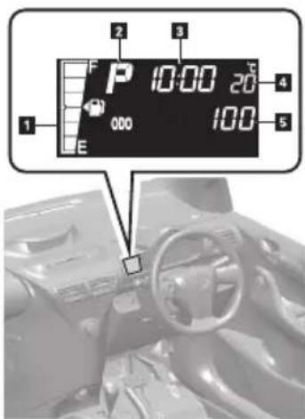
The multi-information display presents the driver with a variety of driving-related information, including the current outside temperature and time.
text_image
1 2 3 4 5 6 7 8 9 10:00 20 000 100- Fuel gauge – Displays the quantity of fuel remaining in the tank.
- Shift position and shift range/gear display (vehicles with a Multidrive) – Displays the shift position along with the currently selected shift range or gear.
- Clock – Displays the time and sets the clock.
- Outside temperature display – Displays the outside air temperature.
- Trip information – Displays odometer, trip meter, fuel consumption and other cruising-related information.
Display items can be switched by pressing the MODE button. (Situated below the display screen.)
text_image
Diagram showing a hand holding a car tire with a red arrow indicating the wheel, and a speech bubble saying 'DO DO' pointing to the steering wheel.

AUTO

text_image
Diagram of a device with directional arrows indicating flow or movement, showing a knob-like device with a sun icon and measurement scale.
text_image
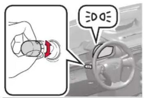
Diagram illustrating car steering wheel and steering wheel with labeled parts and directional arrowsThe headlights can be operated manually or automatically \*
The front position, tail, license plate and instrument panel lights turn on.
The headlights and all lights listed above turn on.
The headlights, front position lights and other lights turn on and off automatically.
(Vehicles without smart entry & start system: When the engine switch is in the ON position.
Vehicles with smart entry & start system: When the "ENGINE START STOP" switch is in IGNITION ON mode).
*On some models
Turning on the high beam headlights
- With the headlights on, push the lever forward to turn on the high beams.
Pull the lever back to the centre position to turn the high beams off.
- You can flash the high beams with the headlights by pulling the lever towards you, and releasing it to turn them off.
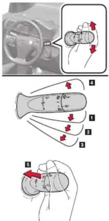
Intermittent wiper
text_image
Diagram illustrating car steering wheel and hand turning process with numbered instructions and directional arrows- Intermittent windscreen wiper operation.
- Low speed windscreen wiper operation.
- High speed windscreen wiper operation.
- Single sweep.
- Washer/wiper dual operation.
Wipers will automatically operate a couple of times after the washer squirts.
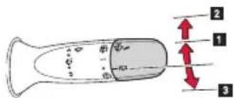
Vehicles without intermittent wiper
text_image
Diagram of a device with labeled parts and directional arrows indicating movement or force- Normal window wiper operation
- Washer/wiper dual operation.
- Washer operation
Rain-sensing windscreen wipers (if equipped)
With "AUTO" selected, the wipers will operate automatically when the sensor detects falling rain. The system automatically adjusts wiper timing in accordance with rain volume and vehicle speed.

text_image
Diagram illustrating hand positioning and movement of a device with numbered parts and directional arrows indicating motion.- Rain-sensing wiper operation.
- Low speed windscreen wiper operation.
- High speed windscreen wiper operation.
- Single sweep.
- Sensor sensitivity (high).
- Sensor sensitivity (low).
Rear window wiper and washer

text_image
Diagram showing car steering wheel and valve mechanism with directional arrows indicating movement or force vectors- Intermittent window wiper operation.
- Normal window wiper operation.
- Washer/wiper dual operation (if equipped).
- Washer operation.
Electric windows and windows lock
Electric windows can be opened and closed using the following switches

text_image
Diagram of car interior with numbered arrows indicating directional changes, showing a hand pressing down on the dashboard.Window lock switch
- Closing.
- One-touch closing*.
- Opening
- One-touch opening*.
*Pressing the switch in the opposite direction will stop window travel partway.
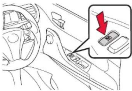
text_image
Diagram of car interior showing dashboard and steering wheel with a red downward arrow indicating a drop or change in the dashboard.Press the switch down to lock the passenger window switch.
Use this switch to prevent children from accidentally opening or closing a passenger window.
Starting your vehicle
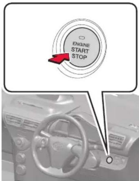
text_image
ENGINE START STOP- Check that the hand brake is on.
- Check that the gear lever is set in N if manual or P if automatic.
- Sit in the driver's seat and firmly depress the clutch pedal for manual, or brake pedal for automatic. The "ENGINE START STOP" switch indicator turns green. If the indicator does not turn green, the engine cannot be started.
- Press the "ENGINE START STOP" switch. The engine can be started from any mode.
Vehicles with manual transmission
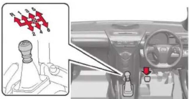
text_image
R 1 3 5 2 4 6Shifting the shift lever - 5 and 6 speed models
Fully depress the clutch pedal before operating the shift lever, and then release the clutch pedal slowly.
Vehicles with Multidrive

text_image
P R N D-S B PShifting the shift lever
When the engine switch is in the "ON" position or the "ENGINE START STOP" switch is in "IGNITION ON", depress the brake pedal and move the shift lever.
Shifting the shift lever to R
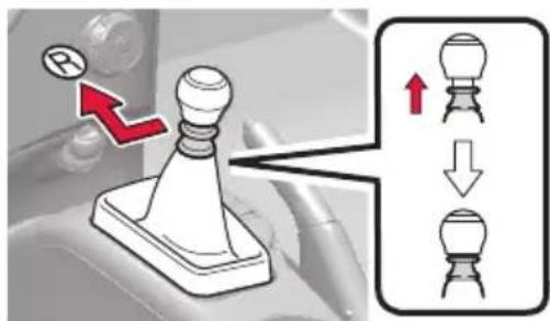
text_image
Diagram illustrating a mechanical switch mechanism with labeled components and directional arrows indicating motion or assembly.Shift the shift lever to the R position while lifting up the ring section.
Vehicles with sport sequential shiftmatic mode

text_image
P R N M-D PShifting the shift lever
When the engine switch is in the "ON" position or the "ENGINE START STOP" switch is in "IGNITION ON", depress the brake pedal and move the shift lever.
Shift position uses
| Shift position | Function | |
| Vehicles without sport sequential shiftmatic mode | Vehicles with sport sequential shiftmatic mode | |
| P Parking the vehicle or starting the engine | ||
| R Reversing | ||
| N Neutral | ||
| D Normal driving* | ||
| M “M” mode driving | ||
| S Engine braking | ||
| B Maximum engine braking | ||
*: To improve fuel consumption and reduce noises, set the shift lever in D for normal driving.
Gear Shift Indicator
The gear shift indicator display is a guide to help the driver achieve improved fuel economy and reduced exhaust emissions within limits of engine performance.
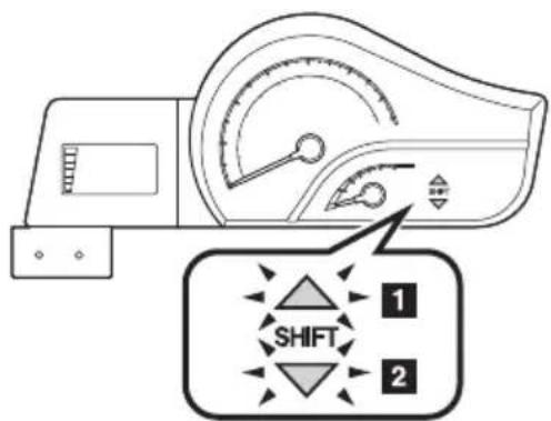
text_image
SHIFT 1 2- Upshifting.
- Downshifting.
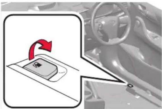
Fuel tank opening
natural_image
Diagram showing a car gear shift lever with red arrow indicating rotation, alongside a vehicle interior view (no text or symbols)Before refueling the vehicle
Turn the engine switch or "ENGINE START STOP" off and ensure that all doors and windows are closed.
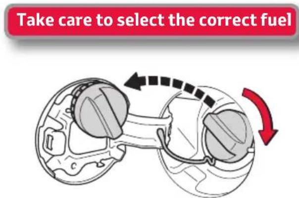
text_image
Take care to select the correct fuelOpening the fuel tank cap
Pull up the fuel filler door opener.
Turn the fuel tank cap slowly to open.
Hang the fuel tank cap on the back of the fuel filler door.
Bonnet opening

natural_image
Interior view of a car dashboard with steering wheel and attached electronic device (no visible text or symbols)
natural_image
Diagram showing a car being inserted into a gear, with an inset highlighting the gear mechanism (no text or symbols present)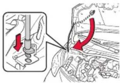
text_image
Technical diagram showing engine component assembly with red arrows indicating direction of movement or changeRelease the lock from inside of the vehicle to open the bonnet.
Pull the bonnet release lever. The bonnet will pop up slightly.
Release the bonnet catch and lift the bonnet.
Hold the bonnet open by inserting the supporting rod into the slot.
Close: gently drop the bonnet from approximately 200mm.
If you have a flat tyre
In case of having a flat tyre, please note that your vehicle does not carry a spare tyre. There is, however, an emergency tyre puncture repair kit.
Location :
Under the rear seats.
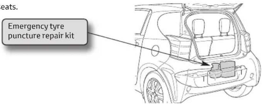
text_image
eats. Emergency tyre puncture repair kitFor full explanation, please consult your Owner's Manual, chapter 5.2
What is "Eco-Driving"?
- Eco-Driving = Driving in a more careful and environmentally responsible way
• Eco-Driving = Reduced fuel costs - Eco-Driving = Reduced Environmental impact > Saving of CO₂ emissions.
Eco-Driving Savings
Total potential saving of 20 - 30%.
Roof load increases wind drag and therefore consumption.
| Roof Load(Speed at 120 km/hr) | Increased consumption |
| Luggage rack 5 – 10% | |
| Ski box 10 – 20% | |
| Bicycle rack 30% | |
| Loaded luggage rack 35 – 40% |
Open windows increase fuel consumption by an average of 5%.

natural_image
Side view of a silver compact car with red measurement lines and logo, no visible text or symbols on the car body.Air Conditioning
can result in 10 - 25% extra fuel consumption.
Low Tyre Pressure result in higher fuel consumption (up to 3% extra from 0.5 bar too low)
Tyre pressures can fall by 2.5 - 5.0% after one month, and by 20% after 5 months.
Shifting up gear
earlier can result
in 8% saving.
How to Eco-Drive?
Starting
- Remove any extra weight and roof load
• Plan your route to avoid detours - Avoid using your car for short journeys
Checking/maintenance
• Check your tyre pressures regularly
• Service your car according to owner's manual
Driving
- Shift up gear earlier
• Only use electrical accessories when necessary (e.g. A/C)
• Follow and anticipate the traffic flow - Keep your windows closed (use ventilation system when possible)
- Switch off your engine if you have to wait longer than 30 - 60 seconds
Think&Act