5350dn - Printer DELL - Free user manual and instructions
Find the device manual for free 5350dn DELL in PDF.

User questions about 5350dn DELL
0 question about this device. Answer the ones you know or ask your own.
Ask a new question about this device
Download the instructions for your Printer in PDF format for free! Find your manual 5350dn - DELL and take your electronic device back in hand. On this page are published all the documents necessary for the use of your device. 5350dn by DELL.
USER MANUAL 5350dn DELL
Information in this document is subject to change without notice.
2010 Dell Inc. All rights reserved.
Reproduction in any manner whatsoever without the written permission of Dell Inc. is strictly forbidden.
Trademarks used in this text: Dell and the DELL logo are trademarks of Dell Inc.
Other trademarks and trade names may be used in this document to refer to the entities claiming the marks and names of their products. Dell Inc. disclaims any proprietary interest in trademarks and trade names other than its own.
Table of contents
Table of contents ..... iii
Notices and safety information ...... xv
Laser notice.... xv
Lithium warning . . . . . . . . . . . . . . . . . . . . . . . . . . . . . . . . . . . . . . . . . . . . . . . . . . . . . . . . . . . . . . . . . . . . . . . . . . . . . . . . . . . . . . . . ii-xxi
Safety information....xxi
Preface .... xxiv
Conventions.... xxiv
General information 1-1
Maintenance approach 1-1
Options 1-2
Available internal options 1-2
Media handling options 1-2
Printer configurations 1-3
Basic model 1-3
Fully configured model 1-4
Supported paper sizes, types, and weights 1-6
Paper sizes supported by the printer 1-6
Paper types and weights supported by the printer 1-7
Paper types and weights supported by the output bins 1-7
Tools required 1-8
Acronyms 1-9
Diagnostic information 2-1
Start 2-1
Confirm the installation status 2-2
Power-on Reset sequence 2-2
Entering Diagnostics mode 2-2
User attendance messages 2-3
Error code table 1 2-14
Service checks 2-120
Sensor (input) service check 2-120
Sensor (fuser output) service check 2-120
Sensor (narrow media) service check 2-121
Sensor (duplex input) service check 2-121
Sensor (duplex input) service check (external duplex only) 2-122
Sensor (duplex exit) service check (external duplex only) 2-122
Sensor (pass through) service check 2-123
Sensor (envelope feeder empty) service check 2-123
Sensor (input) late jam service check. 2-123
Sensor (input) lingering jam service check. 2-126
Sensor (input) early jam service check 2-127
Sensor (input) static jam service check 2-129
Sensor (fuser output) late jam service check. 2-129
Sensor (fuser output) lingering jam service check. 2-131
Sensor (fuser output) static jam service check 2-132
Sensor (narrow media) late jam service check. 2-133
Sensor (narrow media) static jam service check 2-134
Sensor (duplex input) late jam service check. 2-135
Sensor (duplex input) lingering jam service check. 2-136
Sensor (duplex input) static jam service check. 2-138
Sensor (pass through) late jam service check 2-139
Sensor (pass through) lingering jam service check. 2-140
Sensor (pass through) static jam service check 2-141
Sensor (stapler pass through) late jam service check 2-142
Sensor (stapler pass through) lingering jam service check 2-142
Sensor (stapler pass through) static jam service check 2-143
Sensor (output pass through) late jam service check 2-143
Sensor (output pass through) lingering jam service check 2-144
Sensor (output pass through) static jam service check 2-145
Sensor (mailbox empty) late jam service check 2-146
Sensor (mailbox empty) lingering jam service check 2-147
Sensor (mailbox empty) static jam service check 2-147
Sensor (toner empty) service check 2-148
NVRAM mismatch failure (950.00 through 950.29) service check . . . . . . . . . . . . . . . . . . . . . . . . . . . . . . . . . . . . . . . . . . . . . . . . . . . . . . . . . . . . . . . 2-148
Image quality trouble 2-150
Printer Related Troubleshooting 2-150
Image quality symptoms 2-150
Image Quality 2-151
Faint print (Low contrast) 2-151
Blank print (no print) 2-153
Solid black 2-155
Vertical lines and bands (process direction)....2-156
Horizontal white stripes or bands (side to side direction) 2-157
Vertical stripes (process direction) 2-158
Horizontal stripes (side to side direction) 2-159
Partial lack 2-161
Spots 2-162
After image 2-163
Background (fog) 2-165
Skew 2-166
Media damage 2-167
No fuse 2-169
Network service check 2-170
Diagnostic aids 3-1
Understanding the printer control panel (models 5230n/dn, 5350dn, and 5530dn)....3-1
Accessing service menus (models 5230n/dn, 5350dn, and 5530dn). 3-2
Diagnostics mode (models 5230n/dn, 5350dn, and 5530dn)....3-3
Entering Diagnostics mode (models 5230n/dn, 5350dn, and 5530dn) .....3-3
Available tests 3-3
Exiting Diagnostics mode (models 5230n/dn, 5350dn, and 5530dn)....3-5
REGISTRATION 3-5
Quick Test 3-6
PRINT TESTS 3-7
Input source tests 3-7
Print quality pages (Prt Quality Pgs) 3-7
HARDWARE TESTS 3-8
Panel Test 3-8
Button Test 3-8
DRAM Test 3-8
USB HS Test Mode 3-9
RFID Option Test 3-10
DUPLEX TESTS 3-12
Quick Test (duplex) 3-12
Top Margin (duplex) 3-13
Sensor Test (duplex) 3-13
Motor Test (duplex) 3-14
Duplex Feed 1 3-14
Duplex Feed 2 3-14
INPUT TRAY TESTS 3-14
Feed Tests (input tray) 3-15
Sensor Test (input tray) 3-15
OUTPUT BIN TESTS 3-15
Feed Tests (output bins) 3-15
Feed To All Bins 3-16
Sensor Test (standard output bin) 3-16
Sensor Test (Output Expander) 3-17
Sensor Test (high capacity output stacker) 3-17
Sensor Tests (5-bin mailbox) 3-18
Deflector Test 3-18
StapleSmart FINISHER TESTS 3-18
Staple Test 3-18
Feed Tests (finisher) 3-18
Sensor Test (finisher) 3-18
BASE SENSOR TEST 3-19
PRINTER SETUP 3-19
Defaults 3-19
Printed Page Count 3-19
Perm Page Count (permanent page count) 3-20
Serial Number 3-20
Engine Setting 1 through 16 3-20
Model Name 3-20
Configuration ID 3-20
Edge to Edge 3-21
EP SETUP 3-21
EP Defaults 3-21
Fuser Temperature (Fuser Temp) 3-21
Fuser Page Count 3-21
Warm Up Time 3-21
Transfer 3-21
Print Contrast 3-22
Charge Roll 3-22
Gap Adjust 3-22
Auto Dark Adj 3-22
REPORTS 3-23
EVENT LOG 3-23
Display Log 3-23
Print Log 3-23
Clear Log 3-24
EXIT DIAGNOSTICS (models 5230n/dn, 5350dn, and 5530dn). 3-24
Configuration menu (CONFIG MENU) (models 5230n/dn, 5350dn, and 5530dn) 3-25
Entering Configuration Menu (models 5230n/dn, 5350dn, and 5530dn) 3-25
Available menus 3-25
Maintenance page count (Maint Cnt Value) 3-25
Maintenance page counter reset (Reset Cnt) 3-26
Print quality pages (Prt Quality Pgs) 3-26
Reports 3-26
SIZE SENSING 3-27
Panel Menus 3-27
PPDS Emulation 3-27
Demo Mode 3-27
Factory Defaults 3-28
LES Applications 3-28
Energy Conserve 3-28
Paper Prompts 3-28
Env Prompts 3-28
Action for Prompts 3-28
Font Sharpening 3-28
Wiper Messages 3-28
Clear Custom Status 3-28
Best Speed 3-29
Exit Config Menu (models 5230n/dn, 5350dn, and 5530dn). 3-29
Understanding the printer control panel (model T656) 3-29
Accessing service menus (model T656) 3-30
Diagnostics Menu (model T656) 3-31
Entering Diagnostics Menu (model T656) 3-31
Available tests 3-31
Registration (printer) 3-33
Quick Test 3-34
PRINT TESTS 3-35
Input source tests 3-35
Printing Quality Pages 3-35
HARDWARE TESTS 3-36
Panel Test 3-36
Button Test 3-36
DRAM Test 3-37
USB HS Test Mode 3-37
DUPLEX TESTS 3-38
Quick Test (duplex) 3-38
Top Margin (duplex) 3-38
Left Margin (duplex) 3-39
Sensor Test (duplex) 3-39
Motor Test (duplex) 3-39
Duplex Feed 1 3-40
Duplex Feed 2 3-40
INPUT TRAY TESTS 3-40
Feed Tests (input tray) 3-40
Sensor Test (input tray) 3-41
OUTPUT BIN TESTS 3-41
Feed Tests (output bins) 3-41
Sensor Test (standard output bin) 3-41
BASE SENSOR TEST 3-42
DEVICE TESTS 3-43
Quick Disk Test 3-43
Disk Test/Clean 3-43
PRINTER SETUP 3-44
Defaults 3-44
Printed Page Count 3-44
Permanent Page Count 3-44
Serial Number 3-44
Engine Settings 1 through 16 ....3-44
Model Name 3-44
Configuration ID 3-45
Edge to Edge 3-45
EP SETUP 3-45
EP Defaults 3-46
Fuser Temperature (Fuser Temp) 3-46
Fuser Page Count 3-46
Warm Up Time 3-46
Transfer 3-46
Print Contrast 3-46
Charge Roll 3-46
Gap Adjust 3-47
Auto Dark Adjust 3-47
REPORTS 3-47
Menu Settings Page 3-47
EVENT LOG 3-47
Display Log 3-47
Print Log 3-48
Clear Log 3-48
Configuration menu (CONFIG MENU) (model T656) 3-49
Entering Configuration Menu (model T656) 3-49
Available menus 3-49
Maintenance Counter Value 3-49
Reset Maintenance Counter 3-50
Print Quality Pages 3-51
Reports 3-51
Menu Settings Page 3-51
Event Log 3-51
SIZE SENSING 3-52
Panel Menus 3-52
PPDS Emulation 3-52
Factory Defaults 3-54
Energy Conserve 3-54
Paper Prompts 3-55
Envelope Prompts 3-55
Action for Prompts 3-55
Jobs On Disk 3-55
Disk Encryption 3-56
Wipe Disk 3-57
Font Sharpening 3-57
Require Standby 3-57
LES Applications 3-58
Key Repeat Initial Delay 3-58
Key Repeat Rate 3-58
Wiper Message 3-58
Clear Custom Status 3-58
USB speed 3-59
Exit Configuration Menu (model T656) 3-59
Printer overview 3-60
Basic model 3-60
Printer theory 3-61
Model 5230n/dn with duplex, paper path, rolls, and sensors 3-61
Models 5350dn and 5530dn paper path rolls and sensors 3-62
Functions of main components 3-62
Media tray assembly 3-62
Rear media guide 3-62
Side guide 3-63
Wear strips 3-63
Media tray assembly 3-63
Detection of media size 3-63
Pick arm assembly 3-64
Switch (media size) 3-65
Sensor (media empty) 3-65
Sensor (media low) 3-65
Multi-purpose feeder (MPF) 3-65
MPF feed roll 3-65
MPF pick solenoid 3-65
Sensor (MPF media empty) 3-65
Supported paper sizes, types, and weights 3-66
Paper sizes supported by the printer 3-66
Registration 3-67
Sensor (input) 3-67
Aligner assembly 3-67
Transfer 3-68
Transfer roll assembly 3-68
Polygon printhead assembly 3-69
Oscillating printhead assembly 3-71
Fuser 3-72
Fuser components 3-72
Heat roll 3-73
Pressure roll 3-73
Heater lamp 3-73
Thermal cutoff 3-73
Thermistor 3-73
Sensor (fuser output) 3-73
Sensor (narrow media) 3-73
Fuser unit assembly (type 1 and type 2) 3-73
Type 1 fuser unit assembly 3-73
Type 2 fuser unit assembly 3-74
Exit 3-74
Sensor (standard bin full) 3-74
Drive 3-75
Main drive motor assembly 3-75
Redrive motor assembly 3-75
Electrical components and controller 3-76
Switch (printer front door interlock) 3-76
Main cooling fan 3-76
Print cartridge cooling fan 3-76
LVPS card assembly 3-76
HVPS card assembly 3-76
System card assembly 3-77
Control 3-77
Printhead control 3-77
Rotation of printhead motor 3-77
Determination of printhead ready 3-77
Printhead reference value 3-77
Fuser control 3-77
Fuser control method 3-77
Fuser lamp on/off control 3-77
Fuser warm-up 3-78
Xerographic and print cartridge components 3-78
Charge 3-79
Exposure 3-79
Development 3-80
Transfer 3-81
Cleaning 3-82
Auto density sensing 3-83
High Capacity Input Tray (HCIT) tray assembly 3-84
250-sheet/550-sheet tray assembly 3-85
Media size sensing 3-85
Media level sensing 3-86
Pick arm assembly 3-86
Switch (media size) 3-87
Sensor (media empty) 3-87
Sensor (media low) 3-87
Sensor (pass-thru) 3-87
Media transport path 3-89
Model 5230 paper path, rolls, and sensors 3-89
Models 5350dn and 5530dn paper path, rolls, and sensors ....3-90
Functions of main components 3-90
Media tray assembly 3-90
Rear media guide 3-90
Side guide 3-90
Wear strips 3-91
Media tray assembly 3-91
Detection of media size 3-91
Pick arm assembly 3-91
Switch (media size) 3-91
Sensor (media empty) 3-91
Sensor (media low) 3-92
Duplex 3-93
Layout of media transport path 3-93
Model 5230dn duplex paper path 3-93
Models 5350dn and 5530dn duplex paper path 3-94
Functions of main components 3-94
Sensor (duplex input) 3-94
Duplex drive motor assembly 3-95
Understanding jam numbers and locations 3-96
200 and 201 paper jams 3-96
202 and 203 paper jams 3-97
230 paper jam 3-98
Rear paper jams 3-98
Front paper jams 3-99
231-239 paper jams (optional external duplex unit) 3-100
Rear paper jams 3-100
Front paper jams 3-100
241-245 paper jams 3-101
250 paper jam 3-102
260 paper jam 3-103
271-279 paper jams 3-103
280 paper jam 3-104
281 paper jam 3-105
282 paper jam 3-105
283 staple jam 3-106
Security Reset Jumper 3-108
Security Reset Jumper 3-108
Printer skew specifications 3-110
Abnormal skew printer correction 3-110
Print Registration 3-111
Print Position Error 3-111
Repair Information 4-1
Handling ESD-sensitive parts 4-1
Adjustments 4-2
Polygon and Oscillating printhead mechanical registration adjustment 4-2
Oscillating printhead assembly electronic adjustment 4-3
Alignment assembly adjustment 4-4
Fuser solenoid adjustment 4-6
Gap adjustment 4-6
Removals 4-7
Access door removal 4-7
Alignment assembly removal 4-7
Connection access cover, rear removal 4-10
Connection bezel assembly, rear removal (5230n/dn) 4-10
Connection bezel assembly, rear removal (5350dn and 5530dn)....4-11
Cover assembly, rear lower removal (5230n/dn) 4-12
Cover assembly, rear lower (5350dn and 5530dn). 4-12
Charge roll assembly removal 4-12
Door assembly, rear removal 4-14
Duplex guide assembly, rear removal (5350dn, 5530dn, and T656) 4-14
Duplex assembly removal (5350dn, 5530dn, and T656) .....4-16
Duplex cooling fan removal (5350dn, 5530dn, and T656) .....4-17
Duplex drive motor assembly removal (5350dn, 5530dn, and T656) .....4-18
Duplex input sensor assembly removal (5350dn, 5530dn, and T656)....4-19
Duplex guide assembly, front removal (5350dn, 5530dn, and T656)....4-20
Fuser access door assembly removal 4-21
Fuser drive release linkage removal 4-22
Fuser unit assembly removal 4-22
Fuser wiper cover assembly removal 4-23
HVPS card assembly removal 4-24
Inner deflector removal 4-24
Laser cover removal 4-26
LCD screen bezel removal (5230n/dn, 5350dn, and 5530dn) .....4-27
LVPS card assembly removal (5230n/dn) 4-28
LVPS card assembly removal (5350dn, 5530dn, and T656) .....4-30
Main cooling fan removal 4-32
Main drive motor assembly removal 4-33
Media out actuator removal 4-34
Media support removal 4-35
Media turn guide removal 4-35
MPF cam gear removal 4-36
MPF lift plate assembly removal 4-36
MPF media out actuator removal 4-37
MPF pick roll assembly removal 4-37
MPF pick solenoid assembly removal 4-38
MPF tray door assembly removal (5230n/dn, 5350dn, and 5530dn) .....4-40
Operator panel latch assembly removal (5230n/dn, 5350dn, and 5530dn) .....4-42
Operator panel door assembly removal (5230n/dn, 5350dn, and 5530dn) .....4-43
Operator panel hinge assembly, left removal (5230n/dn, 5350dn, and 5530dn) .....4-45
Operator panel hinge assembly, right removal (5230n/dn, 5350dn, and 5530dn) .....4-46
Operator panel door assembly removal (T656) 4-49
Operator panel cover latch assembly removal (T656) 4-52
Option drive shaft removal 4-52
Output cover assembly removal 4-54
Pick arm assembly removal 4-55
Pick roll assembly removal 4-57
Print cartridge cooling fan removal 4-57
Print cartridge clamp assembly removal 4-58
Print cartridge ID connector assembly removal 4-59
Printhead assembly removal (5230n/dn) 4-60
Printhead assembly removal (5350dn, 5530dn, and T656) .....4-61
Redrive assembly removal 4-63
Redrive motor assembly removal (5350dn, 5530dn, and T656) .....4-63
Side cover, left removal (5230n/dn) 4-65
Side cover, left removal (5350dn, 5530dn, and T656) .....4-67
Side cover, right removal (5230n/dn) 4-67
Side cover, right removal (5350dn, 5530dn, and T656) .....4-68
Sensor (duplex input) removal (5350dn, 5530dn, and T656)....4-69
Sensor (media level) removal 4-70
Sensor (media out) removal 4-70
Sensor (toner empty) removal 4-71
Sensor (input) removal 4-71
Sensor shield assembly removal 4-72
Sensor (standard bin exit) removal 4-73
Sensor (toner density) removal 4-73
Standard bin actuator assembly removal 4-73
Switch (media size) assembly removal 4-74
System card assembly removal 4-76
NVM card assembly removal 4-79
Transfer roll assembly removal 4-80
Transfer roll bracket assembly, left removal 4-81
Transfer roll bracket assembly, right removal 4-82
Transfer deflector removal 4-83
Tray roller catch assembly removal 4-83
Option removals 4-85
5-bin mailbox rear door assembly removal 4-85
5-bin mailbox left outer cover removal 4-86
5-bin mailbox left inner cover removal 4-86
5-bin mailbox right outer cover removal 4-87
5-bin mailbox right inner cover removal 4-88
5-bin mailbox top cover removal 4-89
5-bin mailbox media bin full actuator removal 4-90
5-bin mailbox sensor (pass through) removal 4-91
5-bin mailbox sensor (media bin empty) removal 4-92
5-bin mailbox controller card assembly removal 4-93
5-bin mailbox static brush mylar assembly removal 4-94
5-bin mailbox media bin fifth deflector removal 4-95
5-bin mailbox media bin first through fourth deflector removal 4-96
5-bin mailbox media bin extension assembly removal 4-97
5-bin mailbox deflector gate solenoid removal 4-97
5-bin mailbox transport solenoid removal 4-99
5-bin mailbox sensor (deflector gate HP) removal 4-100
250-sheet option tray assembly 4-102
250-sheet media tray assembly removal 4-103
250-sheet pick arm bracket assembly removal 4-103
250-sheet media out actuator removal 4-105
250-sheet frame assembly removal 4-105
250-sheet controller card assembly removal 4-107
550-sheet option tray assembly 4-108
550-sheet media tray assembly removal 4-108
550-sheet pick arm bracket assembly removal 4-109
550-sheet bellcrank recoil spring removal 4-110
550-sheet frame assembly removal 4-111
550-sheet controller card assembly removal 4-112
550-sheet option drive shaft with spring removal 4-114
Anti-tip latch assembly removal 4-114
High capacity input tray (HCIT) 4-115
High capacity input tray (HCIT) media tray assembly removal 4-116
High capacity input tray (HCIT) tray cover, front removal 4-117
High capacity input tray (HCIT) cover, rear removal 4-119
High capacity input tray (HCIT) cover, right removal 4-121
High capacity input tray (HCIT) cover, left removal 4-123
High capacity input tray (HCIT) anti-tip latch assembly removal 4-124
High capacity input tray (HCIT) drawer slide assembly removal 4-125
High capacity input tray (HCIT) tray lift drive motor assembly removal 4-126
High capacity input tray (HCIT) controller card assembly removal 4-127
High capacity input tray (HCIT) media size actuator assembly removal 4-128
High capacity input tray (HCIT) pick arm bracket assembly removal 4-131
High capacity input tray (HCIT) tray closed latch with spring removal 4-133
High capacity stacker rear door assembly removal 4-134
High capacity stacker right cover removal 4-135
High capacity stacker left cover removal 4-136
High capacity stacker media output bin assembly removal 4-137
High capacity stacker controller card cover panel removal 4-138
High capacity stacker switch (media bin HP) removal 4-139
High capacity stacker sensor (media bin full) assembly removal 4-140
High capacity stacker sensor (media bin full) bracket assembly removal 4-140
High capacity stacker controller card assembly (upper and lower) removal 4-141
High capacity stacker right frame removal 4-142
High capacity stacker left frame removal 4-143
High capacity stacker upper deflector gate removal 4-144
High capacity stacker sensor (pass through) removal 4-145
High capacity stacker left mounting bracket removal 4-147
High capacity stacker sensor (deflector gate HP) removal 4-148
Installing / Removing the RFID UHF option 4-149
Lower interface cable assembly removal 4-157
Media size actuator removal 4-158
Media tray catch spring removal 4-159
Media out actuator removal (models 5350dn and 5530dn) .....4-159
Media size actuator removal 4-160
Media tray catch spring removal 4-160
Media tray roller catch assembly removal 4-160
Output expander rear door assembly removal 4-162
Output expander left outer cover removal 4-162
Output expander left inner cover removal 4-163
Output expander right outer cover removal 4-163
Output expander right inner cover removal 4-164
Output expander media bin latch (left and right) removal .....4-164
Output expander media output bin assembly removal 4-165
Output expander media bin full actuator removal 4-165
Output expander sensors (media bin full) assembly removal 4-166
Output expander sensor (media bin full) bracket assembly removal 4-167
Output expander controller card cover panel removal 4-167
Output expander controller card removal 4-169
Output expander sensor (pass through) removal 4-170
Output expander deflector gate removal 4-171
Output expander sensor (deflector gate HP) removal 4-172
SFP stapler assembly rear door assembly removal 4-173
SFP stapler assembly right cover removal 4-173
SFP stapler assembly left cover removal 4-174
SFP stapler assembly top cover removal 4-175
SFP stapler assembly handle cover removal 4-176
SFP stapler assembly LED sensor cover removal 4-177
SFP stapler assembly sensor (finisher bin media present) removal 4-178
SFP stapler assembly standard output bin LED and LED clear lens removal .....4-179
SFP stapler assembly tamper drive belt removal 4-180
SFP stapler assembly tamper drive motor assembly removal 4-181
SFP stapler assembly media stack flap and media stack flap actuator removal .....4-182
SFP stapler assembly stapler unit assembly removal 4-183
SFP stapler assembly paddle drive motor assembly removal 4-184
SFP stapler assembly sensor (media stack) removal 4-185
SFP stapler assembly sensor (paddle HP) removal 4-186
SFP stapler assembly sensor (stapler access door interlock) removal .....4-187
SFP stapler assembly sensor (tamper HP left and right) removal 4-188
SFP stapler assembly sensor (bin full send) removal 4-189
SFP stapler assembly sensor (bin full receive) removal 4-190
SFP stapler assembly sensor (media in stapler) removal 4-190
SFP stapler assembly sensor (deflector HP) removal 4-191
Stapler/stacker controller card assembly removal 4-193
Sensor (HCIT tray raised HP) with cable assembly removal 4-193
Sensor (HCIT pass through) with cable removal 4-196
Sensor (pass through) with cable removal 4-197
Sensor (pass through) with cable removal 4-197
Tray roller catch assembly removal 4-197
Tray roller catch assembly removal 4-198
Upper interface cable assembly removal 4-199
Connector locations and connections.... 5-1
Connections 5-1
Preventive maintenance....6-1
Safety inspection guide 6-1
Lubrication specifications 6-1
Individual maintenance part expected life 6-1
Scheduled maintenance 6-2
Maintenance kit 6-2
Parts catalog 7-1
How to use this parts catalog 7-1
Assembly 1: Covers 7-2
Assembly 2: 5230n/dn, 5350dn, and 5530dn Operator panel 7-4
Assembly 3: T656dne Operator panel, MPF and smart card 7-6
Assembly 4: Drive motor assemblies and duplex 7-8
Assembly 5: Media path and ducts. 7-10
Assembly 6: Printhead, charge, and transfer 7-12
Assembly 7: Pick arm assembly, trays, and MPF 7-14
Assembly 8: LVPS, fuser and electrical cables 1 7-16
Assembly 9: HVPS, system card, and electrical cables 2 7-18
Assembly 10: 250 Sheet option tray assembly 7-20
Assembly 11: 550 Sheet option tray assembly 7-22
Assembly 12: HCIT Sheet option tray assembly 7-24
Assembly 13: SFP stapler assembly #1 7-26
Assembly 14: SFP stapler assembly #2 7-28
Assembly 15: SFP stapler assembly #3 7-30
Assembly 16: SFP stapler assembly #4 7-32
Assembly 17: 5-bin mailbox #1 7-34
Assembly 18: 5-bin mailbox #2 7-36
Assembly 19: High capacity stacker 7-38
Assembly 20: Output expander....7-40
Assembly 21: Envelope feeder and external duplex 7-42
Assembly 22: RFID UHF Option assembly 7-44
Assembly 23: Miscellaneous 7-45
Assembly 24: Power cords 7-47
Assembly 25: Universal trays and accessories 7-48
Index I-1
Part number index I-5
Notices and safety information
The following laser notice labels may be affixed to this printer.
Laser notice
The printer is certified in the U.S. to conform to the requirements of DHHS 21 CFR Subchapter J for Class I (1) laser products, and elsewhere is certified as a Class I laser product conforming to the requirements of IEC 60825-1.
Class I laser products are not considered to be hazardous. The printer contains internally a Class IIIb (3b) laser that is nominally a 5 milliwatt gallium arsenide laser operating in the wavelength region of 770-795 nanometers. The laser system and printer are designed so there is never any human access to laser radiation above a Class I level during normal operation, user maintenance, or prescribed service condition.
Laser
This product contains a lithium battery. THERE IS A RISK OF EXPLOSION IF THE BATTERY IS REPLACED BY AN INCORRECT TYPE. Discard used batteries according to the battery manufacturer's instructions and local regulations.
Safety information
- The safety of this product is based on testing and approvals of the original design and specific components. The manufacturer is not responsible for safety in the event of use of unauthorized replacement parts.
- The maintenance information for this product has been prepared for use by a professional service person and is not intended to be used by others.
- There may be an increased risk of electric shock and personal injury during disassembly and servicing of this product. Professional service personnel should understand this and take necessary precautions.
CAUTION: When you see this symbol, there is a danger from hazardous voltage in the area of the product where you are working. Unplug the product before you begin, or use caution if the product must receive power in order to perform the task.
This manual contains maintenance procedures for service personnel. It is divided into the following chapters:
- General information contains a general description of the printer and the maintenance approach used to repair it. Special tools and test equipment, as well as general environmental and safety instructions, are discussed.
- Diagnostic information contains an error indicator table, symptom tables, and service checks used to isolate failing field replaceable units (FRUs).
- Diagnostic aids contains tests and checks used to locate or repeat symptoms of printer problems.
- Repair information provides instructions for making printer adjustments and removing and installing FRUs.
- Connector locations uses illustrations to identify the connector locations and test points on the printer.
- Preventive maintenance contains the lubrication specifications and recommendations to prevent problems.
- Parts catalog contains illustrations and part numbers for individual FRUs.
Appendix A contains service tips and information.
Appendix B contains representative print samples.
Conventions
Note: A note provides additional information.
Warning: A warning identifies something that might damage the product hardware or software.
There are several types of caution statements:

CAUTION
A caution identifies something that might cause a servicer harm.

CAUTION
This type of caution indicates there is a danger from hazardous voltage in the area of the product where you are working. Unplug the product before you begin, or use caution if the product must receive power in order to perform the task.

CAUTION
This type of caution indicates a hot surface.

CAUTION
This type of caution indicates a tipping hazard.
1. General information
The Dell laser printers are letter-quality page printers designed to attach to personal computers and to most computer networks.
The Dell laser printers are available in the following models:
| Machine type | MFG Model / Dell Model | Configuration |
| 4062-01A | T650n / 5230n/dn | Network |
| T652n4062-21A | Network | |
| 4062-23A | T652dn / 5350dn | Network |
| 4062-41A | T654n | Network |
| T654dn / 5530dn4062-43A | Network | |
| 4062-630 T656dne | Network |
Maintenance approach
The diagnostic information in this manual leads you to the correct field replaceable unit (FRU) or part. Use the service error codes, user status messages, user error messages, service checks, and diagnostic aids to determine the printer problem and repair the failure. After you complete the repair, perform tests as needed to verify the repair. See "Start" on page 2-1.
Options
Available internal options
- Memory cards
- Printer memory
- Flash memory
- Fonts
- Firmware cards
— Bar Code and Forms
— IPDS and SCS/TNe
— PrintCryption ^TM
- PRESCRIBE
- Printer hard disk
• LXK Internal Solutions Ports (ISP)
- RS-232-C serial interface ISP
— Parallel 1284-B interface ISP
— MarkNet ^TM N8150 802.11 b/g/n Wireless ISP
— MarkNet N8130 10/100 Thick Fiber ISP
— MarkNet N8120 10/100/1000 Thick Ethernet ISP
• MarkNet N8110 v.34 Fax Card
The following options are available. Some options are not available in every country. Contact your point of purchase for options available in your country.
Media handling options
— 250- and 550-sheet paper trays of A4, letter, A5, B5, Executive, folio, statement, and legal size
— 250-sheet universally adjustable tray
- 250- and 550-sheet paper drawers
— 2000-sheet high-capacity feeder
— Envelope feeder (Not for use with the T656dne)
— Duplex option— 250-sheet (external)
— Duplex option— 550-sheet (internal on duplex versions of 5350dn and 5530dn)
- Output expander
— High-capacity output stacker
- StapleSmart™ Finisher
- 5-bin Mailbox
— Vertical Kiosk Presenter
— Horizontal Kiosk Presenter
- RFID UHF (only for 5530dn)
Printer configurations
Basic model
The following illustration shows the basic printer model.

text_image
Technical diagram of a printer with numbered parts labeled 1 to 4 for identification.| Feature Paper Capacity | 1 | |
| 1 Standard exit bin 250- or 550-sheet | ||
| 2 Printer control panel NA | ||
| 3 Multipurpose feeder 100 sheets | ||
| 4 Standard tray (Tray 1) 250- or 550-sheets | ||
| ^1 Based on 75 g/m ^2 (20 lb.) paper. | ||
Fully configured model
The following illustration shows the fully configured printer model.

CAUTION: - TIPPING HAZARD: Floor-mounted configurations require additional furniture for stability. You must use either a printer stand or printer base if you are using a 2000-sheet tray, a duplex unit, and an input option, or more than one input option.
More information is available on our Dell Web site at www.dell.com.

text_image
Labeled diagram of a medical imaging machine with numbered components for identification| Feature/Option Paper Capacity | 1 | |
| 1 5-bin mailbox | 2 | 500 sheets |
| 2 Output expander | 3 | 550 sheets |
| 3 Envelope feeder (Not for use with the T656dne) | 85 envelopes | |
| 4 Standard tray (Tray 1) 250 or 550-sheets | ||
| 5 Duplex unit | 4 | Not applicable |
| 6 Optional tray (Tray 2) 250- or 550-sheets | ||
| 7 Optional tray (Tray 3) 250- or 550-sheets | ||
| 8 Optional 2000-sheet tray (Tray 4) 2000 sheets | ||
| 9 Caster base Not applicable | ||
| 1 Based on 75 g/m^2 (20 lb.) paper.2 Up to two 5-bin mailbox units are supported.3 The printer supports up to three output expander units, or one output expander combined with one 5-bin mailbox, one high capacity output expander (not depicted), or one stapler unit (not depicted).4 Optional external duplex unit for the 5230n/dn model. All other models are available with or without internal duplex unit. | ||

CAUTION: Floor-mounted configurations require furniture for stability. You must use either a printer stand or printer base if you are using a 2000-sheet drawer. Certain other configurations also must have a printer stand or printer base.
More information is available on our Dell Web site at www.dell.com.
Supported paper sizes, types, and weights
The following tables provide information on standard and optional paper sources and the types of paper they support.
Note: For an unlisted paper size, select the closest larger listed size.
Paper sizes supported by the printer
| Paper size Dimensions | 250-or 550-sheet trays (standard or optional | Optional 2000-sheet tray | Multipurpose feeder | Duplex unit |
| A4 210 x 297 mm | x | x | x | x |
| A5 148 x 210 mm | x | x | x | |
| A6^1,2 | 105 x 148 mm(4.1 x 5.8 in.) | x | ||
| J15 B5 182 x 257 mm | x | x | x | |
| Letter 216 x 279 mm | x | x | x | x |
| Legal 216 x 356 mm | x | x | x | x |
| Executive 184 x 267 mm | x | x | x | |
| Oficio^1 | x | x | x | |
| Folio^1 | x | x | x | |
| Statement^1 | x | x | ||
| Universal^3,4 | x | x | ||
| 70 x 127 mm(2.8 x 5 in.) up to216 x 356 mm(8.5 x 14 in.) | x | |||
| 148 x 182 mm(5.8 x 7.7 in.) up to216 x 356 mm(8.5 x 14 in.) | x | x | ||
| 7 3/4 Envelopes(Monarch) | 98 x 191 mm(3.9 x 7.5 in.) | x | ||
| 9 Envelope 98 x 225 mm(3.9 x 8.9 in.) | x | |||
| 10 Envelope 105 x 241 mm(4.1 x 9.5 in.) | x | |||
| DL Envelope | 110 x 220 mm(4.3 x 8.7 in) | x |
| Paper size Dimensions | 250-or 550-sheet trays (standard or optional | Optional 2000-sheet tray | Multipurpose feeder | Duplex unit | |
| Other Envelope 98 | x 162 mm(3.9 x 6.4 in.) to 176 x 250 mm(6.9 x 9.8 in.) | x | |||
| ^1 This size appears in the Paper Size menu only when the paper source does not support size sensing or when size sensing is turned off. ^2 Only the standard exit bin supports this size. ^3 This size setting formats the page for 216 x 356 mm (8.5 x 14 in.) unless the size is specified by the software application. ^4 To support duplexing, the Universal width must be between 148 mm (5.8 in) and 216 mm (8.5 in); Universal length must be between 182 mm (7.2 in) and 356 mm (14 in). | |||||
Paper types and weights supported by the printer
| Paper type | 250-or 550-sheet trays (standard or optional | Optional 2000-sheet tray | Multipurpose feeder | Duplex unit |
| Paper• Plain• Bond• Colored• Custom• Letterhead• Light• Heavy• Pre printed• Rough/Cotton• Recycled | x | x | x | x |
| Card stock x | x | x | x | |
| Envelopes x | ||||
| Labels^1 | x | x | x | x |
| Transparencies x | x | x | x | |
| \( ^1Printing labels requires a special label fuser cleaner which prevents duplexing. The label fuser cleaner is included with the special cartridge required for label applications. | ||||
Paper types and weights supported by the output bins
Use this table to determine the possible output destinations of print jobs which use supported paper types and weights. The paper capacity of each output bin is listed in parentheses. Paper capacity estimations are calculated based on 75 g/m^2 (20 lb) paper.
The finisher supports 60-176 g/m2 (16-47 lb) paper weights.
| Paper type | Standard exit bin (350 or 550 sheets) | Optional hardware | ||
| Output Expander (550 sheets) or High Capacity Output stacker (1850 sheets) | 5-Bin Mailbox (500 sheets) ^1 | StapleSmart II Finisher (500 sheets) ^2 | ||
| Paper• Plain• Bond• Colored• Custom• Letterhead• Light• Heavy• Pre printed• Rough/Cotton• Recycled | x | x | x | x |
| Card stock x | x | |||
| Envelopes | ||||
| Labels^1 | x | x | ||
| Transparencies x | x | |||
| \( ^1Supports 60-90 g/m^2 (16-24 lb) paper weights. ^2Maximum of 50 sheets of 75 g/m^2 (20 lb) paper per stapled packet. Results may vary with heavier paper. | ||||
Tools required
Flat-blade screwdrivers, various sizes
1 Phillips screwdriver, magnetic
2 Phillips screwdriver, magnetic
2 Phillips screwdriver, magnetic short-blade
7/32 inch (5.5 mm) open-end wrench
7.0 mm nut driver
Needle nose pliers
Diagonal side cutters
Spring hook
Analog or digital multimeter
Flash light (optional)
Acronyms
BLDC Brushless DC motor
CRU Customer Replaceable Unit
CSU Customer setup
DIMM Dual Inline Memory Module
DRAM Dynamic Random Access Memory
DVM Digital multimeter
EDO Enhanced Data Out
EEPROM Electrically Erasable Programmable Read-Only Memory
EP Electrophotographic process
EPROM Erasable Programmable Read-Only Memory
ESD Electrostatic Discharge
FRU Field Replaceable Unit
GB Gigabyte
HCIT High-capacity Input Tray
HVPS High Voltage Power Supply
ITC Internal Tray Card
LASER Light Amplification by Stimulated Emission of Radiation
LCD Liquid Crystal Display
LED Light-Emitting Diode
LVPS Low Voltage Power Supply
MPF Multipurpose feeder
MROM Masked Read Only Memory
MS Microswitch
NVRAM Nonvolatile Random Access Memory
OEM Original Equipment Manufacturer
OPT Optical Sensor
PC Photoconductor
pel Picture element
POR Power-On Reset
POST Power-On Self Test
PP Parts Packet
PWM Pulse Width Modulation
RFID Radio Frequency Identification
RIP Raster Imaging Processor
ROM Read Only Memory
SDRAM Synchronous Dynamic Random Access Memory
SIMM Single Inline Memory Module
SRAM Static Random Access Memory
UAT Universally Adjustable Tray)
UPR Used Parts Return
V ac Volts alternating current
V dc Volts direct current
VOM Volt Ohmmeter
2. Diagnostic information
Start

CAUTION:
Unplug the power cord from the electrical outlet before you connect or disconnect any cable electronic board or assembly.

CAUTION:
If the printer is kept on, never touch the conductive parts if not specifically required. The power switch and inlet of the low voltage power supply card (LVPS card) assembly is live even while the power supply is cut off. Never touch the live parts.

CAUTION:
Be careful to avoid burns by safely handling hot parts.

CAUTION
The printer weight is greater than 18kg (40 lbs) and requires two or more trained personnel to lift it safely. Use the hand holds on the side of the printer. Make sure your fingers are not under the printer when you lift or set the printer down.
WARNING: When operating the driving units using the diagnostics or other tools, be sure to keep them covered unless otherwise specified.
WARNING: When operating the driving units using the diagnostics or other tools, never touch the driving units. When operating the driving units using diagnostics or other tools, be sure to follow the procedures in this manual.
WARNING: Servicers should wear a wrist band or the like to remove static electricity from their body, grounding their body while working. Go to "Handling ESD-sensitive parts" on page 4-1.
Note: There may be printer error messages that are not contained in this service manual. Call your next level support for assistance.
Confirm the installation status
Be sure to check the following items before starting the troubleshooting procedures.
- With the power cord unplugged from the wall outlet, check that the cord is free from breakage, short-circuit, disconnected wire, or incorrect connection in the power cord.
- The printer is properly grounded. Check the power cord ground terminal.
- The printer is not installed at a place subjected to extreme temperature, extreme humidity or rapid changes in temperature.
- The printer is not installed close to water service, humidifier, heat generating unit, fire, in a very dusty place, or a place exposed to air flow from the air conditioning system.
• The printer is not installed in a place where volatile gas or inflammable gas is generated. - The printer is not installed in direct sun.
- The printer is installed on a level and stable surface.
• Media meets specifications and is installed properly. - Customer maintenance parts have been replaced at the specified intervals.
- Check all attached options for proper attachment and electrical connection.
- Refer to the User's Guide for proper installation.
Power-on Reset sequence
The following is an example of the events that occur during the POR sequence:
- Turn the machine on.
- The fuser cooling fan turns on.
- The fuser unit assembly lamps turn on.
- The system card assembly cooling fan turns on.
- Operator panel LED becomes solid.
-
The transport motor turns on.
-
The Dell splash screen appears with a progress bar in the center until the code is loaded.
Entering Diagnostics mode
- Turn the printer off.
- Press and hold ▼nd . ▶
- Turn the printer on.
- Release the buttons after 10 seconds.
User attendance messages
| Error code or message | Error contents Description/Action Possible repair actions | ||
| System Timeout | System Timeout The system detects a firmware component that is no longer responding. | Turn the power off; wait a few seconds, and then turn the power back on. | |
| 30.XX Invalid Refill Change Cartridge | Message is cleared when a new print cartridge is installed. | Install the proper print cartridge. | |
| 31.XX Defective Cartridge Error code | 31 displays when the top front cover is closed and a defective print cartridge is detected. It may take the printer 10-20 seconds to determine if the print cartridge is defective. | 1. Install the proper print cartridge.2. Ensure the print cartridge ID connector assembly is properly connected.3. Replace the print cartridge ID connector assembly if problem remains. Go to “Print cartridge ID connector assembly removal” on page 4-59. | |
| 32.XX Cartridge part number X unsupported by device | Error 32 displays when the top cover is closed and an unsupported print cartridge is detected. It may take the printer 10-20 seconds to determine if the print cartridge is supported. | Install the proper print cartridge. | |
| 34 Short Paper The printer determines the paper length is too short to print the formatted data. This occurs when the printer does not know the actual paper size loaded in the tray. For auto-size sensing trays, this error occurs if the paper stop is in the incorrect position. Make sure the Paper Size setting is correct for the size paper that is being used. | 1. Ensure the media tray guides are properly set for the media being used.2. Ensure the Switch media size is properly connected.3. Replace the switch media size if problem remains.Go to “Switch (media size) assembly removal” on page 4-74.4. Replace the media tray assembly if problem remains. | ||
| 35 Res Save Off Deficient Memory | This IR is displayed when the printer lacks sufficient memory to enable Resource Save. This message usually indicates the user has allocated too much memory for one or more of the printer's link buffers; however, modification of other printer settings which affect the amount of available memory may also create this condition. If the user desires to enable Resource Save after this message has been posted, it is recommended the user either install additional memory or set each link buffer back to the Auto value.Once all link buffers are returned to Auto, the user should exit the menus to activate the link buffer changes. Once the printer returns to the Ready state, the user may then enable Resource Save and then finally go back and modify the link buffers again. The user should note the reduction of available memory to the link buffers when Resource Save has been enabled as opposed to the memory available when Resource Save is disabled. | This message displays when the printer lacks sufficient memory to enable Resource Save. This message usually indicates the user has allocated too much memory for one or more of the printer link buffers; however, modification of other printer settings which affect the amount of available memory may also create this condition. If restoration of Resource Save is required after this message is received, the customer should install additional memory or set each link buffer to Auto. Once all link buffers are returned to Auto, you should exit the menu to activate the link buffer changes. Once the printer returns to the Ready state, you can enable Resource Save and go back and modify the link buffers again. Note the reduction of available memory to the link buffers when Resource Save has been enabled, and compare it to the memory available when Resource Save is disabled.Press to disable Resource Save and continue printing.To enable Resource Save after you get this message:- Make sure the link buffers are set to Auto, then exit the menus to activate the link buffer changes.- When Ready is displayed, enable Resource Save.Install additional memory. | |
| 37 Insufficient Collation Area | This message displays when the printer memory is insufficient to perform the Flash Memory Defragment operation.Note: This message is posted prior to the actual start of the defragment operation. The printer code determines if enough printer memory is available to complete the defragment operation. The user should not be concerned with losing resources stored in the flash option. | The following actions may be taken:Press to clear the message. To perform the defragment operation:- Delete fonts, macros, and other data in RAM.- Install additional printer memory.Press Full Busy/Waiting appears. The following actions are available:- Cancel Job- Reset Printer- Reset Active Bin | |
| 37 Insufficient Memory This message displays when the printer memory used to restore the Print and Hold jobs from the disk and found that some or all of the jobs could not be restored. The printer ran out of memory while attempting to restore the jobs. | The following actions may be taken:Press to clear the message. Some of the Print and Hold jobs on the disk will not be restored. They remain on the disk, but cannot be accessed.Press [ ] Busy/ Waiting appears. The following functions may be available:- Cancel Job- Reset PrinterReset Active Bin | ||
| 38 Memory Full This message displays when the printer is processing an incoming job and there is insufficient memory available to continue processing the job. | The following actions may be taken:Press to clear the message. Perform the defragment operation:- Perform the defragment operation- Delete fonts, macros, and other data in RAM- Install additional memoryPress to display Busy/ Waiting. The following functions may be available:- Cancel Job- Reset PrinterReset Active Bin | ||
| 39 Complex Page This message displays when the page is too complex to print. The following actions may be taken: | The following actions may be taken:Press to clear the message and continue the job. Some data loss may occur. Simplify the print job and reprint, if necessary.Press [ ] Busy/ Waiting appears. The following selections are possible:- Cancel Job- Reset PrinterReset Active Bin | ||
| Error code or message | Error contents Description/Action Possible repair actions | ||
| 44.01 RFID | Error Bad tag error: a tag has failed to program, or the “Retry Count” has been exceeded.Note: This error is not a data parsing error, but indicates bad RFID media. It is posted only if the “Stop on Error” menu setting is set to “ON”. | 1. Retest using new RFID media.2. Check the RFID firmware card, RFID interface card, RFID cable, and RFID option for correct installation. Go to “High capacity input tray (HCIT) pick arm bracket assembly removal” on page 4-131.3. Replace the RFID UHF option. | |
| 44.11 RFID | Error Generic parse error | 1. These error codes most | likely indicate a problem with the customer’s datastream, and not the RFID Option itself. Ensure there is nothing wrong with the customer’s datastream.2. Check the RFID firmware card, RFID interface card, RFID cable, and RFID option for correct installation. Go to “High capacity input tray (HCIT) pick arm bracket assembly removal” on page 4-131.3. Replace the RFID UHF option. |
| 44.12 RFID | Error Subcommand appears truncated | ||
| 44.13 RFID | Error Subcommand appears longer than expected | ||
| 44.14 RFID | Error Subcommand field value was invalid | ||
| 44.15 RFID | Error Invalid subcommand format (invalid magic byte) | ||
| 44.16 RFID | Error Subcommand format valid but not supported | ||
| 44.17 RFID | Error Illegal chars in subcommand for specified format | ||
| 44.18 RFID | Error Invalid op code | ||
| 44.19 RFID | Error Valid but unsupported op code | ||
| 44.20 RFID | Error Invalid protocol | ||
| 44.21 RFID | Error Valid but unsupported protocol | ||
| 44.22 RFID | Error Unsupported option supplied for operation | ||
| 44.23 RFID | Error Invalid ID length | ||
| 44.24 RFID | Error Invalid ID bit pattern | ||
| 44.25 RFID | Error Too many tags on page (too many means more than one) | ||
| 44.26 RFID | Error Based on tag location | parameters: tag is not compatible with printer | 1. These error codes most likely indicate a problem with the customer's datastream, and not the RFID Option itself. Ensure there is nothing wrong with the customer's datastream.2. Check the RFID firmware card, RFID interface card, RFID cable, and RFID option for correct installation. Go to “High capacity input tray (HCIT) pick arm bracket assembly removal” on page 4-131.3. Replace the RFID UHF option. |
| 44.27 RFID | Error Unsupported SA Code | ||
| 44.28 RFID | Error Invalid Power setting | ||
| 44.29 RFID | Error Unsupported Feature | ||
| 44.31 RFID | Error Generic run-time reader error | ||
| 44.32 RFID | Error Reader response timeout | ||
| 44.33 RFID | Error Garbled or short response from reader | ||
| 44.34 RFID | Error Read/Verify operation failed (tag data from reader != expected value) | 1. Retest using new RFID media2. Check the RFID firmware card, RFID interface card, RFID cable, and RFID option for correct installation. Go to “High capacity input tray (HCIT) pick arm bracket assembly removal” on page 4-131.3. Replace the RFID UHF option. | |
| 44.35 RFID | Error Invalid RFID region 1. Check the RFID firmware | card, RFID interface card, RFID cable, and RFID option for correct installation. Go to “High capacity input tray (HCIT) pick arm bracket assembly removal” on page 4-131.2. Replace the RFID UHF option. | |
| Error code or message | Error contents | Description/Action | Possible repair actions |
| 44.36 RFID | Error Invalid X/Y Position | 1. This error code most likely | indicates a problem with the customer's datastream, and not the RFID Option itself. Ensure there is nothing wrong with the customer's datastream.2. Check the RFID firmware card, RFID interface card, RFID cable, and RFID option for correct installation. Go to "High capacity input tray (HCIT) pick arm bracket assembly removal" on page 4-131.3. Replace the RFID UHF option. |
| 42.XY Cartridge Mismatch | This IR is displayed when the printer detects that the installed cartridge has a region that differs from the below options.To clear this IR, the printer cartridge must be replaced with one that has a proper region.X and Y can have the following values:0 : Worldwide region or Undefined region1 : America2 : EMEA3 : Asia4 : Latin America9 : Invalid region | Install a new toner cartridge that matches the correct regional specification. | |
| 50 PPDS Font Error This message displays when the PPDS interpreter has encountered a font error.Note: This error may only occur when the printer is formatting PPDS print data. | The following actions may be taken:Pressclear the message and continue processing the job.PressBusy/Waiting appears. The following are available:- Cancel Job- Reset Printer- Reset Active Bin | ||
| 51 Defective Flash This message displays when the printer detects a defective flash. This error may occur at power on, or during flash format and write operations. | Pressclear the message. The flash is marked as bad and normal operation continues. Flash operations are not allowed until the problem is resolved. | ||
| Error code or message | Error contents Description/Action Possible repair actions | ||
| 52 Flash Full This message displays when the printer detects an unformatted flash at power on. | Press to clear the message. The flash is marked as bad and normal operation continues. Flash operations are not allowed until the flash is formatted. | ||
| 54 Serial Option [x] Error This IR is displayed when a serial error (framing, parity or overrun) has been detected on the specified optional serial port. This usually indicates that the serial port has not been set up correctly.Once a host interface error has been displayed for the first time, reporting of further host interface errors for the associated port is suppressed until the interface parameters are changed for the associated, or the machine is powered off. | Go to network service check.See “Network service check” on page 2-170. | ||
| 54 Std Network Software Error | This error displays when a network port is detected, but the printer cannot establish communications with it. | The following actions may be taken:Pre to clear the message and continue printing.The job may not print correctly.Program new firmware for the network interface.Reset the printer. | |
| 54 Network [x] Software Error | This error displays when a network port is detected, but the printer cannot establish communications with it. | The following actions may be taken:Press to clear the message and continue printing.The job may not print correctly.Program new firmware for the network interface.Reset the printer. | |
| 55 Unsupported Option in Slot [x] | An unsupported option is installed in the specified solutions port. Power off the printer and remove the unsupported option in the specified slot. | Remove unsupported option. | |
| 56 Parallel Port [x] Disabled | This error displays when data is sent to the printer across an optional parallel port, but the port has been disabled. Once this message displays, reporting of further errors is suppressed until the menus are entered, or the printer is reset. | Go to network service check.See “Network service check” on page 2-170. | |
| 56 Serial Port [x] Disabled | This error displays when data is sent to the printer across an serial port, but the port has been disabled. Once this message displays, reporting of further errors is suppressed until the menus are entered, or the printer is reset. | Go to network service check.See “Network service check” on page 2-170. | |
| 56 Standard USB Port Disabled | Displayed when status is requested over the USB port, but the port has been disabled.Once the error has been displayed for the first time, reporting of further errors is suppressed until the menus are entered or the printer is reset. | The following actions may be taken:Press tyclear the message. The printer discards any data received on the USB port.Press aml Busy/Waiting appears. The following are available:- Reset PrinterReset Active Bin | |
| 56 USB Port [x] Disabled Displayed when status is requested over the USB port, but the port has been disabled.Once the error has been displayed for the first time, reporting of further errors is suppressed until the menus are entered or the printer is reset. | The following actions may be taken:Press tyclear the message. The printer discards any data received on the USB port.Press aml Busy/Waiting appears. The following are available:- Reset PrinterReset Active Bin | ||
| 58 Invalid Tray Configuration | Either no input trays or there are optional trays above the RFID option. | 1. Ensure the RFID option is in first position under printer and that there is at least one input tray beneath the RFID option.2. Check the RFID firmware card, RFID interface card, RFID cable, and RFID option for correct installation. Go to “High capacity input tray (HCIT) pick arm bracket assembly removal” on page 4-131.3. Replace the RFID UHF option. | |
| 58 Too Many Bins Attached | This error code displays when too many bins are attached to the printer. | 1. Turn off and unplug the printer.2. Remove the excess bins.3. Plug in the printer, and turn it on. | |
| Error code or message | Error contents Description/Action Possible repair actions | ||
| 58 Too Many | Disks Installed | This error code displays when too many disks are attached to the printer. | 1. Turn off and unplug the printer.2. Remove the excess disks.3. Plug in the printer, and turn it on. |
| 58 Too Many | Flash Options | This error code displays when too many user flash memory options or too many optional firmware cards have been installed.User can power off and remove extra flash options. | 1. Turn off and unplug the printer.2. Remove the excess flash memory.3. Plug in the printer, and turn it on. |
| 58 Too Many | Trays Attached | This error code displays when too many input trays are attached to the printer.Note: With the RFID option attached, the maximum number of trays is three. Without the RFID option attached, the maximum number is four. | 1. Turn off and unplug the printer.2. Remove the excess trays.3. Plug in the printer, and turn it on. |
| 59 Incompatible | Duplex An incompatible | duplex option is installed.Remove the incompatible duplex option and press √ to clear the message.Note: If the user installed the incompatible device to satisfy a Check Device Connections/reattach message, the user should reinstall an associated compatible option or hot unplug the option. | 1. Turn off and unplug the printer.2. Remove the incompatible external duplex unit assembly.3. Plug in the printer, and turn it on. |
| 59 Incompatible | Envelope Feeder | An incompatible envelope feeder is installed.Remove the incompatible feeder and press √ clear the message.Note: If the user installed the incompatible device to satisfy a Check Device Connections/reattach message, the user should reinstall an associated compatible option or hot unplug the option. | 1. Turn off and unplug the printer.2. Remove the incompatible envelope feeder.3. Plug in the printer, and turn it on. |
| 59 Incompatible Output Bin [x] | An incompatible output bin is installed. For Output Bin x, x=1, 2, or 3.Remove the incompatible output bin and pressclear the message.Note: If the user installed the incompatible device to satisfy a Check Device Connections/reattach message, the user should reinstall an associated compatible option or hot unplug the option. | 1. Turn off and unplug the printer.2. Remove the incompatible output option.3. Plug in the printer, and turn it on. | |
| 59 Incompatible Tray [x] An incompatible tray is installed. For Tray x, x=2, 3, 4, or 5.Remove the incompatible tray and pressclear the message.Note: If the user installed the incompatible device to satisfy a Check Device Connections/reattach message, the user should reinstall an associated compatible option or hot unplug the option. | 1. Turn off and unplug the printer.2. Remove the incompatible trays.3. Plug in the printer, and turn it on. | ||
| 61 Defective | Disk This error code displays when the printer detects a defective disk. This error may occur at power on or during disk format and write operations. While this message displays. | pressclear the message. The disk is marked defective and normal printer operations continue. Disk operations are not allowed with a defective disk. The Format Disk menu is not shown. | |
| 62 Disk Full | This error code displays when there is not enough free space on the disk to hold the resources that have been requested to be written to the disk. This message displays for both resource and PostScript Disk operators when the disk is full. | TBD | |
| 80 Routine | Maintenance Needed | The operator panel displays this message at each 300K page count interval. It is necessary to replace the fuser assembly, transfer roller, charge roll, and pick rolls at this interval to maintain the print quality and reliability of the printer. The parts are available as a maintenance kit. For more information, go to “Scheduled maintenance” on page 6-2. | Scheduled maintenance required.Refer to chapter 6.Go to “Preventive maintenance” on page 6-1. |
| Error code or message | Error contents Description/Action Possible repair actions | ||
| 88 Cartridge | Low This IR is displayed when cartridge low occurs and the cartridge low alarm is activated. If cartridge alarm is not activated, this is not an intervention condition. | Replace the print cartridge. | |
| 88 Cartridge | Nearly Low This IR is displayed when cartridge low occurs and the cartridge low alarm is activated. If cartridge alarm is not activated, this is not an intervention condition. | Replace the print cartridge. | |
| 88 Replace | Cartridge This IR is displayed when toner cartridge is exhausted/empty. | Replace the print cartridge. | |
Error code table 1
| Error code or message | Error contents Description/Action Possible repair actions | ||
| 200.00 Sensor (input) area jam | The media is jammed in the sensor (input) area. | 1. Fan the media and check for obstructions.2. Go to sensor (input) service check.See “Sensor (input) service check” on page 2-120. | |
| 200.01 Sensor (input) lingering jamSource = MPF, duplex or envelope feeder | The media reached the sensor (input) but did not clear it within the specified time. | 1. Fan the media and check for obstructions.2. Go to sensor (input) lingering jam service check.See “Sensor (input) lingering jam service check.” on page 2-126. | |
| 200.02 Sensor (input) lingering jam | The media reached the sensor (input) but did not clear it within the specified time. | 1. Fan the media and ensure it is properly installed.2. Go to sensor (input) lingering jam service check.See “Sensor (input) lingering jam service check.” on page 2-126. | |
| 200.04 Sensor (input) early jam | The media reached the sensor (input) sooner than the specified time.Wrong config ID causes engine to assume 500 paper path on 250 model. | 1. Fan the media and ensure it is properly installed.2. Go to sensor (input) early jam service check.See “Sensor (input) early jam service check” on page 2-127. | |
| 200.06 Sensor (input) early jam | The sensor (input) rebounded once the trailing edge of the media passed. | Go to sensor (input) service check.See “Sensor (input) service check” on page 2-120. | |
| 200.07 Sensor (input) late jamSource = input option tray | The media is late reaching the sensor (input) within the specified time. | Go to sensor (input) late jam service check.See “Sensor (input) late jam service check.” on page 2-123. | |
| 200.08 Sensor (input) early jam | The media reaches the sensor (input) sooner than the specified time. | 1. Fan the media and ensure it is properly installed.2. Go to sensor (input) early jam service check.See “Sensor (input) early jam service check” on page 2-127. | |
| 200.09 Printhead laser start failure | The printhead laser start process failed because it did not receive proper feedback signal from the printhead motor. | 1. Check all connections on the printhead.2. Check all connections on the main drive motor assembly.3. Replace the main drive motor assembly if problem remains. Go to "Output cover assembly removal" on page 4-54. | |
| 200.10 Printhead motor synchronization error | The printhead motor is not synchronized when media reaches the sensor (input). | 1. Remove all media present in media path.2. Check all connections on the printhead.3. Check all connections on the system card assembly.4. Replace the printhead if problem remains. Go to "Printhead assembly removal (5230n/dn)" on page 4-60 or "Printhead assembly removal (5350dn, 5530dn, and T656)" on page 4-61. | |
| 200.11 Printhead polygon mirror synchronization error | The printhead polygon mirror motor becomes un-synchronized when the media reaches the sensor (input). | 1. Remove all media present in media path.2. Check all connections on the printhead.3. Check all connections on the system card assembly.4. Replace the printhead if problem remains. Go to "Printhead assembly removal (5230n/dn)" on page 4-60 or "Printhead assembly removal (5350dn, 5530dn, and T656)", on page 4-61. | |
| 200.12 Laser power signal error | The printhead laser power signal has failed | 1. Remove all media present in media path.2. Check all connections on the printhead.3. Check all connections on the system card assembly.4. Replace the printhead if problem remains. Go to "Printhead assembly removal (5230n/dn)" on page 4-60 or "Printhead assembly removal (5350dn, 5530dn, and T656)" on page 4-60.5. Replace the system card if problem remains. Go to "System card assembly removal" on page 4-76. | |
| Error code or message | Error contents Description/Action Possible repair actions | ||
| 200.13 Sensor (input) static jam | Media remains on the sensor (input) during the warm up sequence. | Go to sensor (input) static jam service check.See “Sensor (input) static jam service check” on page 2-129. | |
| 200.14 Sensor (input) early jam | The media reached the sensor (input) sooner than the specified time. | Go to sensor (input) early jam service check.See “Sensor (input) early jam service check” on page 2-127. | |
| 200.15 Laser power did not settle | Laser circuit failure on printhead or system card assembly. | 1. Remove all media present in media path.2. Check all connections on the printhead.3. Check all connections on the system card assembly.4. Replace the printhead if problem remains. Go to “Printhead assembly removal (5230n/dn)” on page 4-60 or “Printhead assembly removal (5350dn, 5530dn, and T656)” on page 4-61.5. Replace the system card if problem remains. Go to “System card assembly removal” on page 4-76. | |
| 200.16 Main drive motor assembly load error | The main drive motor assembly has failed or caused high mechanical load due to paper jam or bind. | 1. Remove all media present in media path.2. Check all connections on the main drive motor assembly.3. Check all connections on the system card assembly.4. Replace the main drive motor assembly if problem remains. Go to “Output cover assembly removal” on page 4-54. | |
| 200.17 Sensor (input) lingering jamSource = Tray 1Tray level= Not Low | The media reached the sensor (input) but did not clear it within the specified time. | Go to sensor (input) lingering jam service check.See “Sensor (input) lingering jam service check.” on page 2-126. | |
| 200.18 Sensor (input) lingering jamSource = Tray 1Tray level = Low | The media reached the sensor (input) but did not clear it within the specified time. | Go to sensor (input) lingering jam service check.See “Sensor (input) lingering jam service check.” on page 2-126. | |
| 200.19 Sensor (input) lingering jamSource = Tray 1Tray level = Empty | The media reached the sensor (input) but did not clear it within the specified time. | Go to sensor (input) lingering jam service check.See “Sensor (input) lingering jam service check.” on page 2-126. | |
| Error code or message | Error contents Description/Action Possible repair actions | ||
| 200.27 Sensor (input)lingering jamSource = Tray 2Tray level = Not Low | The media reached the sensor (input) but did not clear it within the specified time. | Go to sensor (input) lingering jam service check.See “Sensor (input) lingering jam service check.” on page 2-126. | |
| 200.28 Sensor (input)lingering jamSource = Tray 2Tray level = Low | The media reached the sensor (input) but did not clear it within the specified time. | Go to sensor (input) lingering jam service check.See “Sensor (input) lingering jam service check.” on page 2-126. | |
| 200.29 Sensor (input)lingering jamSource = Tray 2Tray level = Empty | The media reached the sensor (input) but did not clear it within the specified time. | Go to sensor (input) lingering jam service check.See “Sensor (input) lingering jam service check.” on page 2-126. | |
| 200.32 Operator panel door assemblyswitch failure | Operator panel door assembly not fully closed. Interlock switch not functioning correctly. | 1. Ensure that the operator panel door assembly is fully closed.2. Check operator panel door assembly for damage.3. Check interlock switch (in left operator panel hinge) for damage.4. Check all connections on the system card assembly. | |
| 200.33 Sensor (input) early jam | The media reached the sensor (input) sooner than the specified time.Wrong config ID causes engine to assume 500 paper path on 250 model. | 1. Fan the media and ensure it is properly installed.2. Go to sensor (input) early jam service check.See “Sensor (input) early jam service check” on page 2-127. | |
| 200.34 Sensor (toner empty) failure | The sensor (toner empty) has failed or is not sensing the pulse wheel on the print cartridge. | 1. Inspect print cartridge pulse wheel for damage and replace if needed.2. Check the sensor (toner empty) for proper operation.See “Sensor (toner empty) service check” on page 2-148. | |
| 200.37 Sensor (input)lingering jamSource = Tray 3Tray level= Not Low | The media reached the sensor (input) but did not clear it within the specified time. | Go to sensor (input) lingering jam service check.See “Sensor (input) lingering jam service check.” on page 2-126. | |
| 200.38 Sensor (input)lingering jamSource = Tray 3Tray level = Low | The media reached the sensor (input) but did not clear it within the specified time. | Go to sensor (input) lingering jam service check.See “Sensor (input) lingering jam service check.” on page 2-126. | |
| Error code or message | Error contents Description/Action Possible repair actions | ||
| 200.39 Sensor (input)lingering jamSource = Tray 3Tray level = Empty | The media reached the sensor (input) but did not clear it within the specified time. | Go to sensor (input) lingering jam service check.See “Sensor (input) lingering jam service check.” on page 2-126. | |
| 200.47 Sensor (input)lingering jamSource = Tray 4Tray level = Not Low | The media reached the sensor (input) but did not clear it within the specified time. | Go to sensor (input) lingering jam service check.See “Sensor (input) lingering jam service check.” on page 2-126. | |
| 200.48 Sensor (input)lingering jamSource = Tray 4Tray level = Low | The media reached the sensor (input) but did not clear it within the specified time. | Go to sensor (input) lingering jam service check.See “Sensor (input) lingering jam service check.” on page 2-126. | |
| 200.49 Sensor (input)lingering jamSource = Tray 4Tray level = Empty | The media reached the sensor (input) but did not clear it within the specified time. | Go to sensor (input) lingering jam service check.See “Sensor (input) lingering jam service check.” on page 2-126. | |
| 200.57 Sensor (input)lingering jamSource = Tray 5Tray level = Not Low | The media reached the sensor (input) but did not clear it within the specified time. | Go to sensor (input) lingering jam service check.See “Sensor (input) lingering jam service check.” on page 2-126. | |
| 200.58 Sensor (input)lingering jamSource = Tray 5Tray level = Low | The media reached the sensor (input) but did not clear it within the specified time. | Go to sensor (input) lingering jam service check.See “Sensor (input) lingering jam service check.” on page 2-126. | |
| 200.59 Sensor (input)lingering jamSource = Tray 5Tray level = Empty | The media reached the sensor (input) but did not clear it within the specified time. | Go to sensor (input) lingering jam service check.See “Sensor (input) lingering jam service check.” on page 2-126. | |
| 201.00 Sensor (fuser output) area jam.Type 1 fuser | The media is jammed in the sensor (fuser output) area. | Go to sensor (fuser output) service check.See “Sensor (fuser output) service check” on page 2-120. | |
| 201.01 Main drive motor assembly load error.Type 1 fuser | The main drive motor assembly has failed or caused high mechanical load due to paper jam or bind. | 1. Check all connections on the main drive motor assembly.2. Check all connections on the system card assembly.3. Replace the main drive motor assembly if problem remains. Go to “Output cover assembly removal” on page 4-54. | |
| Error code or message | Error contents Description/Action Possible repair actions | ||
| 201.02 Sensor (fuser output) late jam.Type 1 fuser | The media is late reaching the sensor (fuser output) within the specified time. | Go to sensor (fuser output) late jam service check.See “Sensor (fuser output) late jam service check.” on page 2-129.If problem remains, a type 2 fuser can be installed. | |
| 201.03 Image data did not start in timeType 1 fuser | Printhead write failure 1. Check all connections on the printhead assembly2. Check all connections on the system card assembly.3. Replace the printhead assembly if problem remains.4. Replace the system card assembly if problem remains.Go to “System card assembly removal” on page 4-76. | ||
| 201.04 Sensor (narrow media) late jamType 1 fuser | The expected wide media is late reaching the sensor (narrow media) within the specified time. | Go to sensor (narrow media) late jam service check.See “Sensor (narrow media) late jam service check.” on page 2-133. | |
| 201.06 Sensor (narrow media) late jamType 1 fuser | The expected wide media is late reaching the sensor (narrow media) within the specified time. | Go to sensor (narrow media) late jam service check.See “Sensor (narrow media) late jam service check.” on page 2-133. | |
| 201.07 Sensor (fuser output) late jamType 1 fuser | The media is late reaching the sensor (fuser output) within the specified time. | Go to sensor (fuser output) late jam service check.See “Sensor (fuser output) late jam service check.” on page 2-129. | |
| 201.25 Sensor (fuser output) area jam.Type 2 fuser | The media is jammed in the sensor (fuser output) area. | Go to sensor (fuser output) service check.See “Sensor (fuser output) late jam service check.” on page 2-129. | |
| 201.26 Main drive motor assembly load error.Type 2 fuser | The main drive motor assembly has failed or caused high mechanical load due to paper jam or bind. | 1. Check all connections on the main drive motor assembly.2. Check all connections on the system card assembly.3. Replace the main drive motor assembly if problem remains. Go to “Output cover assembly removal” on page 4-54. | |
| Error code or message | Error contents Description/Action Possible repair actions | ||
| 201.27 Sensor (fuser output) late jam.Type 2 fuser | The media is late reaching the sensor (fuser output) within the specified time. | Go to sensor (fuser output) late jam service check.See "Sensor (fuser output) late jam service check." on page 2-129.If problem remains, a type 2 fuser can be installed. | |
| 201.28 Image data did not start in timeType 2 fuser | Printhead write failure 1. Check all connections on the printhead assembly2. Check all connections on the system card assembly.3. Replace the printhead assembly if problem remains.4. Replace the system card assembly if problem remains.Go to "System card assembly removal" on page 4-76. | ||
| 201.29 Sensor (narrow media) late jamType 2 fuser | The expected wide media is late reaching the sensor (narrow media) within the specified time. | Go to sensor (narrow media) late jam service check.See "Sensor (narrow media) late jam service check." on page 2-133. | |
| 201.30 Operator panel door assembly interlock switch failureType 2 fuser | The printer detected that the operator panel door interlock switch did not cycle prior to printer restart. | 1. Remove all media present in media path.2. Ensure that the operator panel door assembly is fully open then fully closed.3. Check operator panel door assembly for damage.4. Check interlock switch (in left operator panel hinge) for damage.5. Check all connections on the system card assembly. | |
| 201.31 Sensor (narrow media) late jamType 2 fuser | The expected wide media is late reaching the sensor (narrow media) within the specified time. | Go to sensor (narrow media) late jam service check.See "Sensor (narrow media) late jam service check." on page 2-133. | |
| 201.32 Sensor (fuser output) late jamType 2 fuser | The media is late reaching the sensor (fuser output) within the specified time. | Go to sensor (fuser output) late jam service check.See "Sensor (fuser output) late jam service check." on page 2-129. | |
| 201.50 Sensor (fuser output) late jamType 1 fuserFuser page count has exceeded life. | The media is late reaching the sensor (fuser output) within the specified time. | Go to sensor (fuser output) service check.See "Sensor (fuser output) service check" on page 2-120. | |
| Error code or message | Error contents Description/Action Possible repair actions | ||
| 201.51 Main | drive motor assembly load error.Type 1 fuserFuser page count has exceeded life. | The main drive motor assembly has failed or caused high mechanical load due to paper jam or bind. | 1. Check all connections on the main drive motor assembly.2. Check all connections on the system card assembly.3. Replace the main drive motor assembly if problem remains. Go to "Output cover assembly removal" on page 4-54. |
| 201.52 Sensor (fuser output) late jamType 1 fuserFuser page count has exceeded life. | The media is late reaching the sensor (fuser output) within the specified time. | Go to sensor (fuser output) late jam service check.See "Sensor (fuser output) late jam service check." on page 2-129.If problem remains, a type 2 fuser can be installed. | |
| 201.53 Image data did not start in timeType 1 fuserFuser page count has exceeded life | Printhead write failure 1. Check all connections on the printhead assemblyType 1 fuserFuser page count has exceeded life | 2. Check all connections on the system card assembly.3. Replace the printhead assembly if problem remains.4. Replace the system card assembly if problem remains. Go to "System card assembly removal" on page 4-76. | |
| 201.54 Sensor (narrow media) late jamType 1 fuserFuser page count has exceeded life | The media is late reaching the sensor (narrow media) within the specified time. | Go to sensor (narrow media) late jam service check.See "Sensor (narrow media) late jam service check." on page 2-133. | |
| 201.55 Operator panel door assembly interlock switch open failureType 1 fuserFuser page count has exceeded life | The printer detected that the switch (operator panel door interlock) did not cycle prior to printer restart. | 1. Remove all media present in media path.2. Ensure that the operator panel door assembly is fully open then fully closed.3. Check operator panel door assembly for damage.4. Check interlock switch (in left operator panel hinge) for damage.5. Check all connections on the system card assembly. | |
| 201.56 Sensor (narrow media) late jamType 1 fuserFuser page count has exceeded life. | The media is late reaching the sensor (narrow media) within the specified time. | Go to sensor (narrow media) late jam service check.See "Sensor (narrow media) late jam service check." on page 2-133. | |
| Error code or message | Error contents Description/Action Possible repair actions | ||
| 201.57 Sensor (fuser output) late jamType 1 fuserFuser page count has exceeded life | The media is late reaching the sensor (fuser output) within the specified time. | Go to sensor (fuser output) late jam service check.See “Sensor (fuser output) late jam service check.” on page 2-129. | |
| 201.75 Sensor (fuser output) late jamType 2 fuserFuser page count has exceeded life. | The media is late reaching the sensor (fuser output) within the specified time. | Go to sensor (fuser output) late jam service check.See “Sensor (fuser output) late jam service check.” on page 2-129. | |
| 201.76 Main drive motor assembly load error.Type 2 fuserFuser page count has exceeded life. | The main drive motor assembly has failed or caused high mechanical load due to paper jam or bind. | 1. Remove all media present in media path.2. Check all connections on the main drive motor assembly.3. Check all connections on the system card assembly.4. Replace the main drive motor assembly if problem remains. Go to “Output cover assembly removal” on page 4-54. | |
| 201.77 Sensor (fuser output) late jamType 2 fuserFuser page count has exceeded life. | The media is late reaching the sensor (fuser output) within the specified time. | Go to sensor (fuser output) late jam service check.See “Sensor (fuser output) late jam service check.” on page 2-129. | |
| 201.78 Image data did not start in timeType 2 fuserFuser page count has exceeded life | Printhead write failure 1. Check all connections on the printhead assembly2. Check all connections on the system card assembly.3. Replace the printhead assembly if problem remains.4. Replace the system card assembly if problem remains. Go to “System card assembly removal” on page 4-76. | ||
| 201.79 Sensor (narrow media) late jamType 2 fuserFuser page count has exceeded life | The media is late reaching the sensor (narrow media) within the specified time. | Go to sensor (narrow media) late jam service check.See “Sensor (narrow media) late jam service check.” on page 2-133. | |
| 201.80 Operator panel door assembly interlock switch open failureType 2 fuserFuser page count has exceeded life | The printer detected that the switch (operator panel door interlock) did not cycle prior to printer restart. | 1. Remove all media present in media path.2. Ensure that the operator panel door assembly is fully open then fully closed.3. Check operator panel door assembly for damage.4. Check interlock switch (in left operator panel hinge) for damage.5. Check all connections on the system card assembly. | |
| 201.81 Sensor (narrow media) late jamType 2 fuserFuser page count has exceeded life. | The media is late reaching the sensor (narrow media) within the specified time. | Go to sensor (narrow media) late jam service check.See “Sensor (narrow media) late jam service check.” on page 2-133. | |
| 201.82 Sensor (fuser output)late jamType 2 fuserFuser page count has exceeded life | The media is late reaching the sensor (fuser output) within the specified time. | Go to sensor (fuser output) late jam service check.See “Sensor (fuser output) late jam service check.” on page 2-129. | |
| 202.00 Paper jam around fuser exit or redrive area.Type 1 fuser | Page may be jammed in fuser exit or redrive area. | 1. Remove all media present in media path.2. Check media for proper installation.3. Check for obstructions in media path.4. Go to sensor (fuser output) service check. See “Sensor (fuser output) service check” on page 2-120.5. Go to sensor (narrow media) service check. See “Sensor (narrow media) service check” on page 2-121. | |
| 202.01 Sensor (fuser output)lingering jam.Destination is standard bin.Type 1 fuser | Media reached the sensor (fuser output) but did not clear it in the specified time.andMedia did not reach the sensor (narrow media) | Go to sensor (fuser output) lingering jam service check.See “Sensor (fuser output) lingering jam service check.” on page 2-131. | |
| 202.02 Sensor (fuser output)lingering jam.Type 1 fuser | Media reached the sensor (fuser output) but did not clear it in the specified time. | Go to sensor (fuser output) lingering jam service check.See “Sensor (fuser output) lingering jam service check.” on page 2-131. | |
| 202.03 Sensor (narrow media) static jamType 1 fuser | Media remains on the sensor (narrow media) during the warm up sequence. | Go to sensor (narrow media) static jam service check.See “Sensor (narrow media) static jam service check” on page 2-134. | |
| Error code or message | Error contents Description/Action Possible repair actions | ||
| 202.04 Sensor (fuser output) bounceType 1 fuser | The sensor (fuser output) rebounded once the trailing edge of the media passed. | Go to sensor (fuser output) service check.See “Sensor (fuser output) service check” on page 2-120. | |
| 202.06 Sensor (fuser output) static jamType 1 fuser | Media remains on the sensor (fuser output) during the warm up sequence. | Go to sensor (fuser output) static jam service check.See “Sensor (fuser output) static jam service check” on page 2-132. | |
| 202.07 Sensor (fuser output) lingering jam.Type 1 fuser | Media reached the sensor (fuser output) but did not clear it in the specified time. | Go to sensor (fuser output) lingering jam service check.See “Sensor (fuser output) lingering jam service check.” on page 2-131. | |
| 202.09 Sensor (fuser output) lingering jam.Type 1 fuser | Media reached the sensor (fuser output) but did not clear it in the specified time. | Go to sensor (fuser output) lingering jam service check.See “Sensor (fuser output) lingering jam service check.” on page 2-131. | |
| 202.10 Sensor (fuser output) lingering jam.Destination is output option.Type 1 fuser | Media reached the sensor (fuser output) but did not clear it in the specified time.andMedia did not reach the sensor (narrow media) | Go to sensor (fuser output) lingering jam service check.See “Sensor (fuser output) lingering jam service check.” on page 2-131. | |
| 202.11 Sensor (fuser output) lingering jam.Destination is standard bin.Type 1 fuser | Media reached the sensor (fuser output) but did not clear it in the specified time.andMedia did reach the sensor (narrow media) | Go to sensor (fuser output) lingering jam service check.See “Sensor (fuser output) lingering jam service check.” on page 2-131. | |
| 202.12 Sensor (fuser output) lingering jam.Destination is output option.Type 1 fuser | Media reached the sensor (fuser output) but did not clear it in the specified time.andMedia did reach the sensor (narrow media) | Go to sensor (fuser output) lingering jam service check.See “Sensor (fuser output) lingering jam service check.” on page 2-131. | |
| 202.13 Sensor (fuser output) static jam andSensor (narrow media) static jamType 1 fuser | Media remains on the sensor (fuser output) and the sensor (narrow media) during the warm up sequence. | 1. Go to sensor (fuser output) static jam service check.See “Sensor (fuser output) static jam service check” on page 2-132.2. Go to sensor (narrow media) static jam service check. See “Sensor (narrow media) static jam service check” on page 2-134. | |
| Error code or message | Error contents Description/Action Possible repair actions | ||
| 202.25 Paper | jam around fuser exit or redrive area.Type 2 fuser | Page may be jammed in fuser exit or redrive area. | 1. Remove all media present in media path.2. Check media for proper installation.3. Check for obstructions in media path.4. Go to sensor (fuser output) service check.5. See "Sensor (fuser output) service check" on page 2-120.6. Go to sensor (narrow media) service check. See "Sensor (narrow media) service check" on page 2-121. |
| 202.26 Sensor | (fuser output) lingering jam.Destination is standard bin.Type 2 fuser | Media reached the sensor (fuser output) but did not clear it in the specified time.andMedia did not reach the sensor (narrow media) | Go to sensor (fuser output) lingering jam service check.See "Sensor (fuser output) lingering jam service check." on page 2-131. |
| 202.27 Sensor | (fuser output) lingering jam.Type 2 fuser | Media reached the sensor (fuser output) but did not clear it in the specified time. | Go to sensor (fuser output) lingering jam service check.See "Sensor (fuser output) lingering jam service check." on page 2-131. |
| 202.28 Sensor | (narrow media) static jamType 2 fuser | Media remains on the sensor (narrow media) during the warm up sequence. | Go to sensor (narrow media) static jam service check.See "Sensor (narrow media) static jam service check" on page 2-134. |
| 202.29 Sensor | (fuser output) bounceType 2 fuser | The sensor (fuser output) rebounded once the trailing edge of the media passed. | Go to sensor (fuser output) service check.See "Sensor (fuser output) service check" on page 2-120. |
| 202.30 Never sent the divert command to the stacker.Type 2 fuser | |||
| 202.31 Sensor | (fuser output) static jamType 2 fuser | Media remains on the sensor (fuser output) during the warm up sequence. | Go to sensor (fuser output) static jam service check.See "Sensor (fuser output) static jam service check" on page 2-132. |
| 202.32 Sensor | (fuser output) lingering jam.Type 2 fuser | Media reached the sensor (fuser output) but did not clear it in the specified time. | Go to sensor (fuser output) lingering jam service check.See "Sensor (fuser output) lingering jam service check." on page 2-131. |
| 202.34 Sensor (fuser output)lingering jam.Type 2 fuser | Media reached the sensor(fuser output) but did not clearit in the specified time. | Go to sensor (fuser output)lingering jam service check.See “Sensor (fuser output)lingering jam service check.”on page 2-131. | |
| 202.35 Sensor (fuser output)lingering jam.Destination is output option.Type 2 fuser | Media reached the sensor(fuser output) but did not clearit in the specified time.andMedia did not reach the sensor(narrow media) | Go to sensor (fuser output)lingering jam service check.See “Sensor (fuser output)lingering jam service check.”on page 2-131. | |
| 202.36 Sensor (fuser output)lingering jam.Destination is standard bin.Type 2 fuser | Media reached the sensor(fuser output) but did not clearit in the specified time.andMedia did reach the sensor(narrow media) | Go to sensor (fuser output)lingering jam service check.See “Sensor (fuser output)lingering jam service check.”on page 2-131. | |
| 202.37 Sensor (fuser output)lingering jam.Destination is output option.Type 2 fuser | Media reached the sensor(fuser output) but did not clearit in the specified time.andMedia did reach the sensor(narrow media) | Go to sensor (fuser output)lingering jam service check.See “Sensor (fuser output)lingering jam service check.”on page 2-131. | |
| 202.38 Sensor (fuser output)static jamandSensor (narrowmedia) static jamType 2 fuser | Media remains on the sensor(fuser output) and the sensor(narrow media) during thewarm up sequence. | 1. Go to sensor (fuser output)static jam service check.See “Sensor (fuseroutput) static jam servicecheck” on page 2-132.2. Go to sensor (narrowmedia) static jam servicecheck. See “Sensor(narrow media) static jamservice check” onpage 2-134. | |
| 202.50 Paper jam aroundfuser exit or redrive area.Type 1 fuserFuser page count hasexceeded life | Page may be jammed in fuserexit or redrive area. | 1. Remove all media presentin media path.2. Check media for properinstallation.3. Check for obstructions inmedia path.4. Go to sensor (fuser output)service check. See“Sensor (fuser output)service check” onpage 2-120.5. Go to sensor (narrowmedia) service check. See“Sensor (narrow media)service check” onpage 2-121. | |
| 202.51 Sensor (fuser output)lingering jam.Destination is standard bin.Type 1 fuserFuser page count has exceeded life. | Media reached the sensor(fuser output) but did not clear it in the specified time. | Go to sensor (fuser output)lingering jam service check.See “Sensor (fuser output)lingering jam service check.”on page 2-131. | |
| 202.52 Sensor (fuser output)lingering jam.Type 1 fuserFuser page count has exceeded life. | Media reached the sensor(fuser output) but did not clear it in the specified time. | Go to sensor (fuser output)lingering jam service check.See “Sensor (fuser output)lingering jam service check.”on page 2-131. | |
| 202.53 Sensor (narrow media) static jamType 1 fuserFuser page count has exceeded life. | Media remains on the sensor(narrow media) during the warm up sequence. | Go to sensor (narrow media)static jam service check.See “Sensor (narrow media)static jam service check” on page 2-134. | |
| 202.54 Sensor (fuser output)bounceType 1 fuserFuser page count has exceeded life. | The sensor (fuser output)rebounded once the trailing edge of the media passed. | Go to sensor (fuser output)service check.See “Sensor (fuser output)service check” onpage 2-120. | |
| 202.56 Sensor (fuser output)static jamType 1 fuserFuser page count has exceeded life. | Media remains on the sensor(fuser output) during the warm up sequence. | Go to sensor (fuser output)static jam service check.See “Sensor (fuser output)static jam service check” onpage 2-132. | |
| 202.57 Sensor (fuser output)lingering jam.Type 1 fuserFuser page count has exceeded life. | Media reached the sensor(fuser output) but did not clear it in the specified time. | Go to sensor (fuser output)lingering jam service check.See “Sensor (fuser output)lingering jam service check.”on page 2-131. | |
| 202.59 Sensor (fuser output)lingering jam.Type 1 fuserFuser page count has exceeded life. | Media reached the sensor(fuser output) but did not clear it in the specified time. | Go to sensor (fuser output)lingering jam service check.See “Sensor (fuser output)lingering jam service check.”on page 2-131. | |
| 202.60 Sensor (fuser output)lingering jam.Destination is output option.Type 1 fuserFuser page count has exceeded life. | Media reached the sensor(fuser output) but did not clear it in the specified time.andMedia did not reach the sensor(narrow media) | Go to sensor (fuser output)lingering jam service check.See “Sensor (fuser output)lingering jam service check.”on page 2-131. | |
| 202.61 Sensor (fuser output)lingering jam.Destination is standard bin.Type 1 fuserFuser page count has exceeded life. | Media reached the sensor(fuser output) but did not clear it in the specified time.andMedia did reach the sensor(narrow media) | Go to sensor (fuser output)lingering jam service check.See “Sensor (fuser output)lingering jam service check.”on page 2-131. | |
| 202.62 Sensor (fuser output)lingering jam.Destination is output option.Type 1 fuserFuser page count has exceeded life. | Media reached the sensor(fuser output) but did not clear it in the specified time.andMedia did reach the sensor(narrow media) | Go to sensor (fuser output)lingering jam service check.See “Sensor (fuser output)lingering jam service check.”on page 2-131. | |
| 202.63 Sensor (fuser output)static jamandSensor (narrow media) static jamType 1 fuserFuser page count has exceeded life. | Media remains on the sensor(fuser output) and the sensor(narrow media) during the warm up sequence. | 1. Go to sensor (fuser output)static jam service check.See “Sensor (fuser output) static jam service check” on page 2-132.2. Go to sensor (narrow media) static jam service check. See “Sensor(narrow media) static jam service check” onpage 2-134. | |
| 202.75 Paper jam aroundfuser exit or redrive area.Type 2 fuserFuser page count has exceeded life. | Page may be jammed in fuser exit or redrive area. | 1. Remove all media present in media path.2. Check media for proper installation.3. Check for obstructions in media path.4. Go to sensor (fuser output)service check. See“Sensor (fuser output)service check” onpage 2-120.5. Go to sensor (narrow media) service check. See“Sensor (narrow media)service check” onpage 2-121. | |
| 202.76 Sensor (fuser output)lingering jam.Destination is standard bin.Type 2 fuserFuser page count has exceeded life. | Media reached the sensor(fuser output) but did not clear it in the specified time.andMedia did not reach the sensor(narrow media) | Go to sensor (fuser output)lingering jam service check.See “Sensor (fuser output)lingering jam service check.”on page 2-131. | |
| 202.77 Sensor (fuser output)lingering jam.Type 2 fuserFuser page count has exceeded life. | Media reached the sensor(fuser output) but did not clear it in the specified time. | Go to sensor (fuser output)lingering jam service check.See “Sensor (fuser output)lingering jam service check.”on page 2-131. | |
| 202.78 Sensor (narrow media) static jamType 2 fuserFuser page count has exceeded life. | Media remains on the sensor (narrow media) during the warm up sequence. | 1. Go to sensor (fuser output) static jam service check.See “Sensor (fuser output) static jam service check” on page 2-132.2. Go to sensor (narrow media) static jam service check. See “Sensor (narrow media) static jam service check” on page 2-134. | |
| 202.79 Sensor (fuser output) bounceType 2 fuserFuser page count has exceeded life. | The sensor (fuser output) rebounded once the trailing edge of the media passed. | Go to sensor (fuser output) service check.See “Sensor (fuser output) service check” on page 2-120. | |
| 202.81 Sensor (fuser output) static jamType 2 fuserFuser page count has exceeded life. | Media remains on the sensor (fuser output) during the warm up sequence. | Go to sensor (fuser output) static jam service check.See “Sensor (fuser output) static jam service check” on page 2-132. | |
| 202.82 Sensor (fuser output) lingering jam.Type 2 fuserFuser page count has exceeded life. | Media reached the sensor (fuser output) but did not clear it in the specified time. | Go to sensor (fuser output) lingering jam service check.See “Sensor (fuser output) lingering jam service check.” on page 2-131. | |
| 202.84 Sensor (fuser output) lingering jam.Type 2 fuserFuser page count has exceeded life. | Media reached the sensor (fuser output) but did not clear it in the specified time. | Go to sensor (fuser output) lingering jam service check.See “Sensor (fuser output) lingering jam service check.” on page 2-131. | |
| 202.85 Sensor (fuser output) lingering jam.Destination is output option.Type 2 fuserFuser page count has exceeded life. | Media reached the sensor (fuser output) but did not clear it in the specified time.andMedia did not reach the sensor (narrow media) | Go to sensor (fuser output) lingering jam service check.See “Sensor (fuser output) lingering jam service check.” on page 2-131. | |
| 202.86 Sensor (fuser output) lingering jam.Destination is standard bin.Type 2 fuserFuser page count has exceeded life. | Media reached the sensor (fuser output) but did not clear it in the specified time.andMedia did reach the sensor (narrow media) | Go to sensor (fuser output) lingering jam service check.See “Sensor (fuser output) lingering jam service check.” on page 2-131. | |
| Error code or message | Error contents Description/Action Possible repair actions | ||
| 202.87 Sensor (fuser output)lingering jam.Destination is output option.Type 2 fuserFuser page count has exceeded life. | Media reached the sensor(fuser output) but did not clear it in the specified time.andMedia did reach the sensor(narrow media) | Go to sensor (fuser output)lingering jam service check.See “Sensor (fuser output)lingering jam service check.”on page 2-131. | |
| 202.88 Sensor (fuser output)static jamandSensor (narrow media) static jamType 2 fuserFuser page count has exceeded life. | Media remains on the sensor(fuser output) and the sensor(narrow media) during the warm up sequence. | 1. Go to sensor (fuser output)static jam service check.See “Sensor (fuser output) static jam service check” on page 2-132.2. Go to sensor (narrow media) static jam service check. See “Sensor(narrow media) static jam service check” onpage 2-134. | |
| 202.99 Fuser ID chip failure The system does not recognize the ID chip on the fuser unit. | Replace the fuser unit assembly.Go to “Fuser unit assemblyremoval” on page 4-22, | ||
| 203.00 Paper jam around redrive area. | Page may be jammed in redrive area. | 1. Remove all media present in media path.2. Check media for proper installation.3. Check for obstructions in media path.4. Go to sensor (fuser output)service check. See“Sensor (fuser output)service check” onpage 2-120.5. Go to sensor (narrow media) service check. See“Sensor (narrow media)service check” onpage 2-121. | |
| 203.01 Internal duplex drivemotor control failure.Internal duplex | The internal duplex drive motor motor does not reach the proper operating speed at the specified time. | 1. Remove all media present in media path.2. Check all connections on the duplex media entrance drive motor assembly.3. Check all connections on the system card assembly.4. Replace the duplex media entrance drive motor assembly if problem remains. Go to “Duplexdrive motor assemblyremoval (5350dn, 5530dn,and T656)” on page 4-18. | |
| 203.08 Redrive motor load error | The redrive motor assembly has failed or caused high mechanical load during the warm up sequence. | 1. Remove all media present in media path.2. Ensure that upper redive assembly is properly installed.3. Check all connections on the redrive motor assembly.4. Check all connections on the system card assembly.5. Replace the redrive motor assembly if problem remains. Go to “Redrive assembly removal” on page 4-63. | |
| 203.10 Redrive motor control failure.Media tray 1 | The redrive motor does not reach the proper operating speed at the specified time. | 1. Remove all media present in media path.2. Ensure that upper redive assembly is properly installed.3. Check all connections on the redrive motor assembly.4. Check all connections on the system card assembly.5. Replace the redrive motor assembly if problem remains. Go to “Redrive assembly removal” on page 4-63. | |
| 203.18 Redrive motor assembly underspeed error. | The redrive motor assembly does not rotate at the specified speed. | 1. Remove all media present in media path.2. Ensure that upper redive assembly is properly installed.3. Check all connections on the redrive motor assembly.4. Check all connections on the system card assembly.5. Replace the redrive motor assembly if problem remains. Go to “Redrive assembly removal” on page 4-63. | |
| 203.20 Redrive motor lost encoder failure | The redrive motor is not reporting pulses back to the engine. | 1. Check all connections on the redrive motor assembly.2. Check all connections on the system card assembly.3. Replace the redrive motor assembly if problem remains. Go to “Redrive assembly removal” on page 4-63. | |
| 230.00 Paper jam around internal duplex.Source = Internal duplex | Page may be jammed in internal duplex area. | 1. Remove all media present in media path.2. Check for obstructions in media path.3. Go to sensor (fuser output) service check. See “Sensor (fuser output) service check” on page 2-120.4. Go to sensor (duplex input) service check. See “Sensor (duplex input) service check” on page 2-121. | |
| 230.01 Sensor (duplex input) lingering jamSource = Internal duplex | Media reached the sensor (duplex input) but did not clear it in the specified time. | Go to sensor (duplex input) lingering jam service check.See “Sensor (pass through) late jam service check” on page 2-139. | |
| 230.02 Sensor (duplex input) late jamSource = Internal duplex | Media is late reaching the sensor (duplex input) within the specified time. | Go to sensor (duplex input) late jam service check.See “Sensor (duplex input) late jam service check.” on page 2-135. | |
| 230.03 Sensor (duplex input) bounceSource = Internal duplex | The sensor (duplex input) rebounded once the trailing edge of the media passed. | Go to sensor (duplex input) service check. See “Sensor (duplex input) service check” on page 2-121. | |
| 230.04 Sensor (input) late jam from duplexSource = Internal duplex | Media is late reaching the sensor (input) within the specified time during the second side printing using the internal duplex. | Go to sensor (input) late jam service check.See “Sensor (input) late jam service check.” on page 2-123. | |
| 230.05 sensor (duplex input) lingering jamSource = Internal duplex | Media reached the sensor (duplex input) but did not clear it in the specified time. | Go to sensor (duplex input) lingering jam service check.See “Sensor (pass through) late jam service check” on page 2-139. | |
| 230.06 Sensor (input) late jam from duplexSource = Internal duplex | Media is late reaching the sensor (input) within the specified time during the second side printing using the internal duplex. | Go to sensor (input) late jam service check.See “Sensor (input) late jam service check.” on page 2-123. | |
| 230.07 Sensor (input) late jam from duplexSource = Internal duplex | Media is late reaching the sensor (input) within the specified time during the second side printing using the internal duplex. | Go to sensor (input) late jam service check.See “Sensor (input) late jam service check.” on page 2-123. | |
| Error code or message | Error contents Description/Action Possible repair actions | ||
| 230.08 Internal duplex drive motor load errorSource = Internal duplex | The internal duplex drive motor assembly has failed or caused high mechanical load during warm up sequence. | 1. Remove all media present in media path.2. Check all connections on the duplex media entrance drive motor assembly.3. Check all connections on the system card assembly.4. Replace the duplex drive motor assembly if problem remains. Go to “Duplex drive motor assembly removal (5350dn, 5530dn, and T656)” on page 4-18. | |
| 230.10 Internal duplex drive motor control failure.Source = Internal duplex | The internal duplex drive motor motor does not reach the proper operating speed at the specified time. | 1. Remove all media present in media path.2. Check all connections on the duplex media entrance drive motor assembly.3. Check all connections on the system card assembly.4. Replace the duplex media entrance drive motor assembly if problem remains. Go to “Duplex drive motor assembly removal (5350dn, 5530dn, and T656)” on page 4-18. | |
| 230.13 sensor (duplex input) static jamSource = Internal duplex | Media remains on the sensor (duplex input) during the warm up sequence. | Go to sensor (duplex input) static jam service check.See “Sensor (duplex input) lingering jam service check.” on page 2-136. | |
| 230.14 Paper jam around internal duplex.Source = Internal duplex | Page may be jammed in internal duplex area. | 1. Remove all media present in media path.2. Check for obstructions in media path.3. Go to sensor (fuser output) service check. See “Sensor (fuser output) service check” on page 2-120.4. Go to sensor (duplex input) service check. See “Sensor (duplex input) service check” on page 2-121. | |
| Error code or message | Error contents Description/Action Possible repair actions | ||
| 230.18 Internal duplex drive motor assembly underspeed error.Source = Internal duplex | The internal duplex drive motor does not rotate at the specified speed. | Remove all media present in media path.Check all connections on the duplex media entrance drive motor assembly.Check all connections on the system card assembly.Replace the duplex media entrance drive motor assembly if problem remains. Go to “Duplex drive motor assembly removal (5350dn, 5530dn, and T656)” on page 4-18. | |
| 230.20 Internal duplex drive motor lost encoder failureSource = Internal duplex | The internal duplex drive motor is not reporting pulses back to the engine. | Remove all media present in media path.Check all connections on the duplex media entrance drive motor assembly.Check all connections on the system card assembly.Replace the duplex drive motor assembly if problem remains. Go to “Duplex drive motor assembly removal (5350dn, 5530dn, and T656)” on page 4-18. | |
| 231.00 Sensor (duplex input) late jamSource = External duplex | Media is late reaching the sensor (duplex input) within the specified time. | Go to sensor (duplex input) late jam service check.See “Sensor (duplex input) late jam service check.” on page 2-135. | |
| 232.00 Sensor (duplex input) lingering jamSource = External duplex | Media reached the sensor (duplex input) but did not clear it in the specified time. | Go to sensor (duplex input) lingering jam service check.See “Sensor (pass through) late jam service check” on page 2-139. | |
| 233.00 Sensor (duplex double-feed) late jamSource = External duplex | Media is late reaching the sensor (duplex double-feed) within the specified time. | Remove all media present in media path.Check for obstructions in media path.Ensure the external duplex assembly is properly installed.Ensure the rear door of the external duplex is fully closed.Check all connections on the external duplex assembly.Replace the external duplex assembly if problem remains. | |
| Error code or message | Error contents Description/Action Possible repair actions | ||
| 234.00 Sensor (duplex exit) late jamSource = External duplex | Media is late reaching the sensor (duplex exit) within the specified time. | 1. Remove all media present in media path.2. Check media for proper installation.3. Check for obstructions in media path.4. Ensure the external duplex assembly is properly installed.5. Ensure the rear door of the external duplex is fully closed.6. Check sensor (duplex exit) for proper operation. See “Sensor (duplex exit) service check (external duplex only)” on page 2-122.7. Check all connections on the external duplex assembly.8. Replace the external duplex assembly if problem remains. | |
| 235.00 Sensor (duplex double-feed) lingering jamSource = External duplex | Media reached the sensor (duplex double-feed) within the specified time but did not clear it within the specified time. | 1. Remove all media present in media path.2. Check media for proper installation.3. Check for obstructions in media path.4. Ensure the external duplex assembly is properly installed.5. Replace the external duplex assembly if problem remains. | |
| 236.00 Sensor (duplex exit) lingering jamSource = External duplex | Media reached the sensor (duplex exit) within the specified time but did not clear it within the specified time. | 1. Remove all media present in media path.2. Check media for proper installation.3. Check for obstructions in media path.4. Ensure the external duplex assembly is properly installed.5. Check sensor (duplex exit) for proper operation.See “Sensor (duplex exit) service check (external duplex only)” on page 2-122.6. Replace the external duplex assembly if problem remains. | |
| 237.00 Sensor (input) late jam from duplexSource = External duplex | Media is late reaching the sensor (input) within the specified time during the second side printing using the external duplex. | Go to sensor (input) late jam service check.See “Sensor (input) late jam service check.” on page 2-123. | |
| Error code or message | Error contents Description/Action Possible repair actions | ||
| 237.07 Paper jam around external duplexSource = External duplex. | Page may be jammed in external duplex area. | 1. Remove all media present in media path.2. Check media for proper installation.3. Check for obstructions in media path.4. Ensure the external duplex assembly is properly installed.5. Ensure the rear door of the external duplex is fully closed.6. Ensure the external duplex tray is fully closed.7. Ensure the media tray 1 is fully closed.8. Check the lower option drive (PTO) assembly for damage.9. Check all connections on the external duplex assembly.10. Replace the external duplex assembly if problem remains. | |
| 238.00 External duplex sensor static jamSource = External duplex | Media remains on a sensor within the external duplex assembly during the warm up sequence. | 1. Remove all media present in media path.2. Replace the external duplex assembly if problem remains. | |
| 238.01 Sensor (duplex input) static jamSource = External duplex | Media remains on the sensor (duplex input) during the warm up sequence. | Go to sensor (duplex input) static jam service check.See “Sensor (duplex input) lingering jam service check.” on page 2-136. | |
| 238.02 Sensor (duplex exit) static jamSource = External duplex | Media remains on the sensor (duplex exit) during the warm up sequence. | 1. Remove all media present in media path.2. Go to sensor (duplex exit) service check. See “Sensor (duplex exit) service check (external duplex only)” on page 2-122.3. Replace the external duplex assembly if problem remains. | |
| 238.03 Sensor (duplex input) static jamSensor (duplex exit) static jamSource = External duplex | Media remains on the sensor (duplex input) and the sensor (duplex exit) during the warm up sequence. | Go to sensor (duplex input) static jam service check.See “Sensor (duplex input) lingering jam service check.” on page 2-136. | |
| Error code or message | Error contents Description/Action Possible repair actions | ||
| 238.04 Sensor (duplex double-feed) static jamSource = External duplex | Media remains on the sensor (duplex double-feed) during the warm up sequence. | 1. Remove all media present in media path.2. Replace the external duplex assembly if problem remains. | |
| 238.05 Sensor (duplex input) static jamSensor (double-feed) static jamSource = External duplex | Media remains on the sensor (duplex input) and the sensor (double-feed) during the warm up sequence. | 1. Remove all media present in media path.2. Go to sensor (duplex input) static jam service check.See “Sensor (duplex input) lingering jam service check.” on page 2-136. | |
| 238.06 Sensor (duplex exit) static jamSensor (double-feed) static jamSource = External duplex | Media remains on the sensor (duplex exit) and the sensor (double-feed) during the warm up sequence. | 1. Remove all media present in media path.2. Go to sensor (duplex exit) service check. See “Sensor (duplex exit) service check (external duplex only)” on page 2-122.3. Replace the external duplex assembly if problem remains. | |
| 238.07 Sensor (duplex input) static jamSensor (double-feed) static jamSensor (duplex exit)Source = External duplex | Media remains on the sensor (duplex input), sensor (double-feed) and the sensor (duplex exit) during the warm up sequence. | Go to sensor (duplex input) static jam service check.See “Sensor (duplex input) lingering jam service check.” on page 2-136. | |
| 239.00 Mechanical feed error or timing error.Source = External duplex | Mechanical feed error or timing error. | 1. Remove all media present in media path.2. Check sensor (duplex input) for proper operation.See “Sensor (duplex input) service check” on page 2-121.3. Check sensor (duplex exit) for proper operation. See “Sensor (duplex exit) service check (external duplex only)” on page 2-122.4. Replace the external duplex assembly if problem remains. | |
| 239.01 External duplex assembly errorSource = External duplex | Mechanical feed error or timing error. | 1. Remove all media present in media path.2. Check media for proper installation.3. Check for obstructions in media path.4. Ensure the external duplex assembly is properly installed.5. Ensure the rear door of the external duplex is fully closed.6. Check all connections on the external duplex assembly.7. Replace the external duplex assembly if problem remains. | |
| 239.02 External duplex assembly errorSource = External duplex | Mechanical feed error or timing error. | 1. Remove all media present in media path.2. Check media for proper installation.3. Check for obstructions in media path.4. Ensure the external duplex assembly is properly installed.5. Ensure the rear door of the external duplex is fully closed.6. Check all connections on the external duplex assembly.7. Replace the external duplex assembly if problem remains. | |
| 238.03 Device controls response error.Source = External duplex | Mechanical feed error or timing error. | 1. Remove all media present in media path.2. Check media for proper installation.3. Check for obstructions in media path.4. Ensure the external duplex assembly is properly installed.5. Ensure the rear door of the external duplex is fully closed.6. Check all connections on the external duplex assembly.7. Replace the external duplex assembly if problem remains. | |
| 239.04 Input | device ready response error.Source = External duplex | Mechanical feed error or timing error. | 1. Remove all media present in media path.2. Check media for proper installation.3. Check for obstructions in media path.4. Ensure the external duplex assembly is properly installed.5. Ensure the rear door of the external duplex is fully closed.6. Check all connections on the external duplex assembly.7. Replace the external duplex assembly if problem remains. |
| 239.05 Output | device response error.Source = External duplex | Mechanical feed error or timing error. | 1. Remove all media present in media path.2. Check media for proper installation.3. Check for obstructions in media path.4. Ensure the external duplex assembly is properly installed.5. Ensure the rear door of the external duplex is fully closed.6. Check all connections on the external duplex assembly.7. Replace the external duplex assembly if problem remains. |
| 239.06 Failed | the last page of a staple job.Source = External duplex | Mechanical feed error or timing error. | 1. Remove all media present in media path.2. Check media for proper installation.3. Check for obstructions in media path.4. Ensure the external duplex assembly is properly installed.5. Ensure the rear door of the external duplex is fully closed.6. Check all connections on the external duplex assembly.7. Replace the external duplex assembly if problem remains. |
| 239.07 Select output device error.Source = External duplex | Mechanical feed error or timing error. | 1. Remove all media present in media path.2. Check media for proper installation.3. Check for obstructions in media path.4. Ensure the external duplex assembly is properly installed.5. Ensure the rear door of the external duplex is fully closed.6. Check all connections on the external duplex assembly.7. Replace the external duplex assembly if problem remains. | |
| 239.08 Input source ready error.Source = External duplex | Mechanical feed error or timing error. | 1. Remove all media present in media path.2. Check media for proper installation.3. Check for obstructions in media path.4. Ensure the external duplex assembly is properly installed.5. Ensure the rear door of the external duplex is fully closed.6. Check all connections on the external duplex assembly.7. Replace the external duplex assembly if problem remains. | |
| 239.11 Sensor (input) late jam from duplexSource = External duplex | Media is late reaching the sensor (input) within the specified time during the second side printing using the external duplex. | Go to sensor (input) late jam service check.See “Sensor (input) late jam service check.” on page 2-123. | |
| 241.00 Media tray 1 area jamSource = Tray 1 | The media is jammed in the media tray 1 area. | 1. Remove all media present in media path.2. Check media for proper installation.3. Check for obstructions in media path. | |
| 241.01 Pick | motor control failure.Media tray 1 | The pick motor does not reach the proper operating speed at the specified time. | 1. Remove all media present in media path.2. Ensure media tray is not overfilled.3. Check all connections on the pick arm assembly.4. Check all connections on the system card assembly.5. Replace the pick arm assembly if problem remains. Go to “Operator panel door assembly removal (T656)” on page 4-49.6. Replace system card assembly if problem remains. Go to “System card assembly removal” on page 4-76. |
| 241.06 Sensor (input) late jamSource = Tray 1 or MPF | The media is late reaching the sensor (input) within the specified time. | Go to sensor (input) late jam service check.See “Sensor (input) late jam service check.” on page 2-123. | |
| 241.07 Pick | motor load errorSource = Media tray 1 | The pick motor has failed or caused high mechanical load due to paper jam or bind. | 1. Remove all media present in media path.2. Ensure media tray is not overfilled.3. Check, clean or replace the pick rolls for wear and excess contamination. Go to “Pick roll assembly removal” on page 4-57.4. Check all connections on the pick arm assembly.5. Check all connections on the system card assembly.6. Replace the pick arm assembly if problem remains. Go to “Operator panel door assembly removal (T656)” on page 4-49.7. Replace system card assembly if problem remains. Go to “System card assembly removal” on page 4-76. |
| 241.08 Pick | motor load errorSource = Media tray 1 | The pick motor has failed or caused high mechanical load due to paper jam or bind. | 1. Remove all media present in media path.2. Ensure media tray is not overfilled.3. Check, clean or replace the pick rolls for wear and excess contamination. Go to “Pick roll assembly removal” on page 4-57.4. Check all connections on the pick arm assembly.5. Check all connections on the system card assembly.6. Replace the pick arm assembly if problem remains. Go to “Operator panel door assembly removal (T656)” on page 4-49.7. Replace system card assembly if problem remains. Go to “System card assembly removal” on page 4-76. |
| 241.10 Sensor (input) late jamSource = Tray 1 | The media is late reaching the sensor (input) within the specified time. | Go to sensor (input) late jam service check.See “Sensor (input) late jam service check.” on page 2-123. | |
| 241.11 Sensor (input) late jamSource = Tray 1 | The media is late reaching the sensor (input) within the specified time. | Go to sensor (input) late jam service check.See “Sensor (input) late jam service check.” on page 2-123. | |
| 241.12 Sensor (input) late jamSource = Tray 1 or envelope feeder | The media is late reaching the sensor (input) within the specified time. | Go to sensor (input) late jam service check.See “Sensor (input) late jam service check.” on page 2-123. | |
| 241.14 Sensor (input) late jamSource = Tray 1 or envelope feeder | The media is late reaching the sensor (input) within the specified time. | Go to sensor (input) late jam service check.See “Sensor (input) late jam service check.” on page 2-123. | |
| 241.15 Sensor (input) late jamSource = Tray 1 or envelope feeder | The media is late reaching the sensor (input) within the specified time. | Go to sensor (input) late jam service check.See “Sensor (input) late jam service check.” on page 2-123. | |
| 241.16 Sensor (input) late jamSource = Tray 1 | The media is late reaching the sensor (input) within the specified time. | Go to sensor (input) late jam service check.See “Sensor (input) late jam service check.” on page 2-123. | |
| 241.18 Sensor (input) late jamSource = Tray 1 | The media is late reaching the sensor (input) within the specified time. | Go to sensor (input) late jam service check.See “Sensor (input) late jam service check.” on page 2-123. | |
| 241.19 Pick motor control failure.Source = Tray 1 | The pick motor does not reach the proper operating speed at the specified time. | 1. Remove all media present in media path.2. Ensure media tray is not overfilled.3. Check all connections on the pick arm assembly.4. Check all connections on the system card assembly.5. Replace the pick arm assembly if problem remains. Go to “Operator panel door assembly removal (T656)” on page 4-49.6. Replace system card assembly if problem remains. Go to “System card assembly removal” on page 4-76. | |
| 241.20 Tray 1 pick motor lost encoder failureSource = Tray 1 | The pick motor is not reporting pulses back to the engine. | 1. Check all connections on the pick arm assembly.2. Check all connections on the system card assembly.3. Replace the pick arm assembly if problem remains. Go to “Operator panel door assembly removal (T656)” on page 4-49. | |
| 242.00 Media tray 2 area jamSource = Tray 2 | The media is jammed in the media tray 2 area. | 1. Remove all media present in media path.2. Check media for proper installation.3. Check for obstructions in media path. | |
| 242.02 Sensor (pass through) late jamSource = Tray 2 | The media is late reaching the sensor (pass through) within the specified time. | Go to sensor (pass through) late jam service check.See “Sensor (pass through) late jam service check” on page 2-139. | |
| 242.03 Sensor (pass through) late jamSource = Tray 2 | The media is late reaching the sensor (pass through) within the specified time. | Go to sensor (pass through) late jam service check.See “Sensor (pass through) late jam service check” on page 2-139. | |
| 242.04 Sensor (pass through) late jamSource = Tray 2 | The media is late reaching the sensor (pass through) within the specified time. | Go to sensor (pass through) late jam service check.See “Sensor (pass through) late jam service check” on page 2-139. | |
| 242.05 Sensor (pass through) late jamSource = Tray 2 | The media is late reaching the sensor (pass through) within the specified time. | Go to sensor (pass through) late jam service check.See “Sensor (pass through) late jam service check” on page 2-139. | |
| 242.06 Sensor (pass through) late jamSource = Tray 2 | The media is late reaching the sensor (pass through) within the specified time. | Go to sensor (pass through) late jam service check.See “Sensor (pass through) late jam service check” on page 2-139. | |
| 242.08 Sensor (pass through) lingering jamSource = Tray 2 | Media reached the sensor (pass through) within the specified time but did not clear it within the specified time. | Go to sensor (pass through) lingering jam service check.See “Sensor (pass through) lingering jam service check.” on page 2-140. | |
| 242.09 Sensor (input) late jamSource = Tray 2 | The media is late reaching the sensor (input) within the specified time. | Go to sensor (input) late jam service check.See “Sensor (input) late jam service check.” on page 2-123. | |
| 242.10 sensor (pass through) late jamSource = Tray 2 | The media is late reaching the sensor (pass through) within the specified time. | Go to sensor (pass through) late jam service check.See “Sensor (pass through) late jam service check” on page 2-139. | |
| 242.13 Sensor (pass through) static jamSource = Tray 2 | Media remains on the sensor (input) during the warm up sequence. | Go to sensor (pass through) static jam service check.See “Sensor (pass through) static jam service check” on page 2-141. | |
| 242.16 sensor (pass through) late jamSource = Tray 2 | The media is late reaching the sensor (pass through) within the specified time. | Go to sensor (pass through) late jam service check.See “Sensor (pass through) late jam service check” on page 2-139. | |
| 242.17 Media tray pulled jamSource = Tray 2 | A media tray above the source tray was pulled during the printing process. | 1. Remove all media present in media path.2. Close all media trays. | |
| 242.18 Pick retry timeoutSource = Tray 2 | The engine timed out waiting for the tray 2 to report ready before the first pick attempt. | Turn the machine off/on. | |
| 242.19 Pick retry timeoutSource = Tray 2 | The engine timed out waiting for the tray 2 to report ready before a pick retry attempt. | Turn the machine off/on. | |
| 242.52 Tray | 2 pick motor overrun failureSource = Tray 2 | The Pick motor encoder continues to detect pulses after the motor was turned off. | 1. Check all connections on the pick arm assembly.2. Check all connections on the system card assembly.3. Replace the pick arm assembly if problem remains. Go to “Operator panel door assembly removal (T656)” on page 4-49. |
| 242.33 Tray | 2 not readySource = Tray 2 | Tray was not properly pushed into the machine. | 1. Check the size sensing fingers on the media tray for damage2. Replace the media tray assembly if problem remains.3. Check the switch (media size) for proper connection.4. Replace the switch (media size) if problem remains. Go to “Switch (media size) assembly removal” on page 4-74. |
| 242.34 Empty | tray pick attemptedSource = Tray 2 | The pick arm attempted to pick with no media in the tray. | 1. Check the media out actuator for damage.2. Replace the media out actuator if problem remains. Go to “Tray roller catch assembly removal” on page 4-83. |
| 242.35 Pick | page received while POR not yet done.Source = Tray 2 | Media remains on the sensor (input) during the warm up sequence. | Go to sensor (pass through) static jam service check.See “Sensor (pass through) static jam service check” on page 2-141. |
| 242.36 Sensor | (pass through) static jamSource = Tray 2 | Media remains on the sensor (input) during the warm up sequence. | Go to sensor (pass through) static jam service check.See “Sensor (pass through) static jam service check” on page 2-141. |
| 242.37 Sensor | (pass through) late jamSource = Tray 2 | The media is late reaching the sensor (pass through) within the specified time. | Go to sensor (pass through) late jam service check.See “Sensor (pass through) late jam service check” on page 2-139. |
| 242.39 Media | A tray pulled jam A media | tray above the source tray was pulled during the printing process. | 1. Remove all media present in media path.2. Close all media trays. |
| 242.40 Sensor | (pass through) lingering jamSource = Tray 2 | Media reached the sensor (pass through) within the specified time but did not clear it within the specified time. | Go to sensor (pass through) lingering jam service check.See “Sensor (pass through) lingering jam service check.” on page 2-140. |
| 242.49 HCIT | tray lift motor stalled failureSource = Tray 2 | The HCIT tray lift motor has stalled or has become obstructed. | 1. Ensure the HCIT media tray assembly is properly inserted into the machine.2. Check the HCIT tray lift motor assembly for binding or damage.3. Replace the HCIT tray lift drive motor assembly if problem remains.Go to “High capacity input tray (HCIT) tray lift drive motor assembly removal” on page 4-126. |
| 242.50 HCIT | tray lift motor underspeed failureSource = Tray 2 | The HCIT tray lift motor does not rotate at the specified speed. | 1. Ensure the HCIT media tray assembly is properly inserted into the machine.2. Check the HCIT tray lift drive motor assembly for binding or damage.3. Replace the HCIT tray lift motor assembly if problem remains.Go to “High capacity input tray (HCIT) tray lift drive motor assembly removal” on page 4-126. |
| 242.52 HCIT | tray lift motor overrun failureSource = Tray 2 | The HCIT tray lift motor continues to detect pulses after the motor has turned off. | 1. Ensure the HCIT media tray assembly is properly inserted into the machine.2. Check the HCIT tray lift motor assembly for binding or damage.3. Replace the HCIT tray lift drive motor assembly if problem remains.Go to “High capacity input tray (HCIT) tray lift drive motor assembly removal” on page 4-126. |
| 242.65 Pick | motor load errorSource = Media tray 2 | The pick motor has failed or caused high mechanical load due to paper jam or bind. | 1. Remove all media present in media path.2. Ensure media tray is not overfilled.3. Check, clean or replace the pick rolls for wear and excess contamination. Go to “Pick roll assembly removal” on page 4-57.4. Check all connections on the pick arm assembly.5. Check all connections on the system card assembly.6. Replace the pick arm assembly if problem remains. Go to “Operator panel door assembly removal (T656)” on page 4-49.7. Replace system card assembly if problem remains. Go to “System card assembly removal” on page 4-76. |
| 242.66 Pick | motor underspeed failureSource = Media tray 2 | The pick motor does not rotate at the specified speed. | 1. Remove all media present in media path.2. Ensure media tray is not overfilled.3. Check all connections on the pick arm assembly.4. Check all connections on the system card assembly.5. Replace the pick arm assembly if problem remains. Go to “Operator panel door assembly removal (T656)” on page 4-49.6. Replace system card assembly if problem remains. Go to “System card assembly removal” on page 4-76. |
| Error code or message | Error contents Description/Action Possible repair actions | ||
| 242.67 Pick | motor overspeed failureSource = Media tray 2 | The pick motor does not rotate at the specified speed. | 1. Remove all media present in media path.2. Ensure media tray is not overfilled.3. Check all connections on the pick arm assembly.4. Check all connections on the system card assembly.5. Replace the pick arm assembly if problem remains. Go to “Operator panel door assembly removal (T656)” on page 4-49.6. Replace system card assembly if problem remains. Go to “System card assembly removal” on page 4-76. |
| 242.68 Pick | motor stop errorSource = Media tray 2 | Pick motor stop error detected by options tray x | 1. Remove all media present in media path.2. Ensure media tray is not overfilled.3. Check all connections on the pick arm assembly.4. Check all connections on the system card assembly.5. Replace the pick arm assembly if problem remains. Go to “Operator panel door assembly removal (T656)” on page 4-49.6. Replace system card assembly if problem remains. Go to “System card assembly removal” on page 4- 76. |
| 242.69 Pick | motor control failure.Source = Media tray 2 | The pick motor does not reach the proper operating speed at the specified time. | 1. Remove all media present in media path.2. Ensure media tray is not overfilled.3. Check all connections on the pick arm assembly.4. Check all connections on the system card assembly.5. Replace the pick arm assembly if problem remains. Go to “Operator panel door assembly removal (T656)” on page 4-49.6. Replace system card assembly if problem remains. Go to “System card assembly removal” on page 4 -76. |
| 243.00 Media | a tray 3 area jam The media is jammed in the media tray 3 area. | 1. Remove all media present in media path.2. Check media for proper installation.3. Check for obstructions in media path. | |
| 243.02 Sensor | (pass through) late jamSource = Tray 3 | The media is late reaching the sensor (pass through) within the specified time. | Go to sensor (pass through) late jam service check.See “Sensor (pass through) late jam service check” on page 2-139. |
| 243.03 Sensor | (pass through) late jamSource = Tray 3 | The media is late reaching the sensor (pass through) within the specified time. | Go to sensor (pass through) late jam service check.See “Sensor (pass through) late jam service check” on page 2-139. |
| 243.04 Sensor | (pass through) late jamSource = Tray 3 | The media is late reaching the sensor (pass through) within the specified time. | Go to sensor (pass through) late jam service check.See “Sensor (pass through) late jam service check” on page 2-139. |
| 243.05 Sensor | (pass through) late jamSource = Tray 3 | The media is late reaching the sensor (pass through) within the specified time. | Go to sensor (pass through) late jam service check.See “Sensor (pass through) late jam service check” on page 2-139. |
| 243.06 Sensor | (pass through) late jamSource = Tray 3 | The media is late reaching the sensor (pass through) within the specified time. | Go to sensor (pass through) late jam service check.See “Sensor (pass through) late jam service check” on page 2-139. |
| 243.08 Sensor | (pass through) lingering jamSource = Tray 3 | Media reached the sensor (pass through) within the specified time but did not clear it within the specified time. | Go to sensor (pass through) lingering jam service check.See “Sensor (pass through) lingering jam service check.” on page 2-140. |
| 243.10 Sensor | (pass through) late jamSource = Tray 3 | The media is late reaching the sensor (pass through) within the specified time. | Go to sensor (pass through) late jam service check.See “Sensor (pass through) late jam service check” on page 2-139. |
| 243.13 Sensor | (pass through) static jamSource = Tray 3 | Media remains on the sensor (input) during the warm up sequence. | Go to sensor (pass through) static jam service check.See “Sensor (pass through) static jam service check” on page 2-141. |
| 243.16 Sensor | (pass through) late jamSource = Tray 3 | The media is late reaching the sensor (pass through) within the specified time. | Go to sensor (pass through) late jam service check.See “Sensor (pass through) late jam service check” on page 2-139. |
| Error code or message | Error contents Description/Action Possible repair actions | ||
| 243.17 Media | a tray pulled jamSource = Tray 3 | A media tray above the source tray was pulled during the printing process. | 1. Remove all media present in media path.2. Close all media trays. |
| 243.18 Pick | retry timeoutSource = Tray 3 | The engine timed out waiting for the tray 3 to report ready before the first pick attempt. | Turn the machine off/on. |
| 243.19 Pick | retry timeoutSource = Tray 3 | The engine timed out waiting for the tray 3 to report ready before a pick retry attempt. | Turn the machine off/on. |
| 243.33 Tray | 3 not readySource = Tray 3 | Tray was not properly pushed into the machine. | 1. Check the size sensing fingers on the media tray for damage2. Replace the media tray assembly if problem remains.3. Check the switch (media size) for proper connection.4. Replace the switch (media size) if problem remains.Go to “Switch (media size) assembly removal” on page 4-74. |
| 243.34 Empty | try pick attemptedSource = Tray 3 | The pick arm attempted to pick with no media in the tray. | 1. Check the media out actuator for damage.2. Replace the media out actuator if problem remains. Go to “Tray roller catch assembly removal” on page 4-83. |
| 243.35 Pick | page received while POR not yet done.Source = Tray 3 | Media remains on the sensor (input) during the warm up sequence. | Go to sensor (pass through) static jam service check.See “Sensor (pass through) static jam service check” on page 2-141. |
| 243.36 Sensor | (pass through) static jamSource = Tray 3 | Media remains on the sensor (input) during the warm up sequence. | Go to sensor (pass through) static jam service check.See “Sensor (pass through) static jam service check” on page 2-141. |
| 243.37 Sensor | (pass through) late jamSource = Tray 3 | The media is late reaching the sensor (pass through) within the specified time. | Go to sensor (pass through) late jam service check.See “Sensor (pass through) late jam service check” on page 2-139. |
| 243.39 Media | a tray pulled jamSource = Tray 3 | A media tray above the source tray was pulled during the printing process. | 1. Remove all media present in media path.2. Close all media trays. |
| 243.40 Sensor | (pass through) lingering jamSource = Tray 3 | Media reached the sensor (pass through) within the specified time but did not clear it within the specified time. | Go to sensor (pass through) lingering jam service check.See “Sensor (pass through) lingering jam service check.” on page 2-140. |
| 243.49 HCIT | tray lift motor stalled failureSource = Tray 3 | The HCIT tray lift motor has stalled or has become obstructed. | 1. Ensure the HCIT media tray assembly is properly inserted into the machine.2. Check the HCIT tray lift motor assembly for binding or damage.3. Replace the HCIT tray lift drive motor assembly if problem remains.Go to “High capacity input tray (HCIT) tray lift drive motor assembly removal” on page 4-126. |
| 243.50 HCIT | tray lift motor underspeed failureSource = Tray 3 | The HCIT tray lift motor does not rotate at the specified speed. | 1. Ensure the HCIT media tray assembly is properly inserted into the machine.2. Check the HCIT tray lift motor assembly for binding or damage.3. Replace the HCIT tray lift drive motor assembly if problem remains.Go to “High capacity input tray (HCIT) tray lift drive motor assembly removal” on page 4-126. |
| 243.52 HCIT | tray lift motor overrun failureSource = Tray 3 | The HCIT tray lift motor continues to detect pulses after the motor has turned off. | 1. Ensure the HCIT media tray assembly is properly inserted into the machine.2. Check the HCIT tray lift motor assembly for binding or damage.3. Replace the HCIT tray lift drive motor assembly if problem remains.Go to “High capacity input tray (HCIT) tray lift drive motor assembly removal” on page 4-126. |
| 243.65 Pick | motor load errorSource = Media tray 3 | The pick motor has failed or caused high mechanical load due to paper jam or bind. | 1. Remove all media present in media path.2. Ensure media tray is not overfilled.3. Check, clean or replace the pick rolls for wear and excess contamination. Go to “Pick roll assembly removal” on page 4-57.4. Check all connections on the pick arm assembly.5. Check all connections on the system card assembly.6. Replace the pick arm assembly if problem remains. Go to “Operator panel door assembly removal (T656)” on page 4-49.7. Replace system card assembly if problem remains. Go to “System card assembly removal” on page 4-76. |
| 243.66 Pick | motor underspeed failureSource = Media tray 3 | The pick motor does not rotate at the specified speed. | 1. Remove all media present in media path.2. Ensure media tray is not overfilled.3. Check all connections on the pick arm assembly.4. Check all connections on the system card assembly.5. Replace the pick arm assembly if problem remains. Go to “Operator panel door assembly removal (T656)” on page 4-49.6. Replace system card assembly if problem remains. Go to “System card assembly removal” on page 4-76. |
| Error code or message | Error contents Description/Action Possible repair actions | ||
| 243.67 Pick | motor overspeed failureSource = Media tray 3 | The pick motor does not rotate at the specified speed. | 1. Remove all media present in media path.2. Ensure media tray is not overfilled.3. Check all connections on the pick arm assembly.4. Check all connections on the system card assembly.5. Replace the pick arm assembly if problem remains. Go to “Operator panel door assembly removal (T656)” on page 4-49.6. Replace system card assembly if problem remains. Go to “System card assembly removal” on page 4-76. |
| 243.68 Pick | motor stop errorSource = Media tray 3 | Pick motor stop error detected by options tray x | 1. Remove all media present in media path.2. Ensure media tray is not overfilled.3. Check all connections on the pick arm assembly.4. Check all connections on the system card assembly.5. Replace the pick arm assembly if problem remains. Go to “Operator panel door assembly removal (T656)” on page 4-49.6. Replace system card assembly if problem remains. Go to “System card assembly removal” on page 4- 76. |
| 243.69 Pick | motor control failure.Source = Media tray 3 | The pick motor does not reach the proper operating speed at the specified time. | 1. Remove all media present in media path.2. Ensure media tray is not overfilled.3. Check all connections on the pick arm assembly.4. Check all connections on the system card assembly.5. Replace the pick arm assembly if problem remains. Go to “Operator panel door assembly removal (T656)” on page 4-49.6. Replace system card assembly if problem remains. Go to “System card assembly removal” on page 4 -76. |
| Error code or message | Error contents Description/Action Possible repair actions | ||
| 244.00 Media | a tray 4 area jam The media is jammed in the media tray 4 area. | 1. Remove all media present in media path.2. Check media for proper installation.3. Check for obstructions in media path. | |
| 244.02 Sensor | (pass through) late jamSource = Tray 4 | The media is late reaching the sensor (pass through) within the specified time. | Go to sensor (pass through) late jam service check.See “Sensor (pass through) late jam service check” on page 2-139. |
| 244.03 Sensor | (pass through) late jamSource = Tray 4 | The media is late reaching the sensor (pass through) within the specified time. | Go to sensor (pass through) late jam service check.See “Sensor (pass through) late jam service check” on page 2-139. |
| 244.04 Sensor | (pass through) late jamSource = Tray 4 | The media is late reaching the sensor (pass through) within the specified time. | Go to sensor (pass through) late jam service check.See “Sensor (pass through) late jam service check” on page 2-139. |
| 244.05 Sensor | (pass through) late jamSource = Tray 4 | The media is late reaching the sensor (pass through) within the specified time. | Go to sensor (pass through) late jam service check.See “Sensor (pass through) late jam service check” on page 2-139. |
| 244.06 Sensor | (pass through) late jamSource = Tray 4 | The media is late reaching the sensor (pass through) within the specified time. | Go to sensor (pass through) late jam service check.See “Sensor (pass through) late jam service check” on page 2-139. |
| 244.08 Sensor | (pass through) lingering jamSource = Tray 4 | Media reached the sensor (pass through) within the specified time but did not clear it within the specified time. | Go to sensor (pass through) lingering jam service check.See “Sensor (pass through) lingering jam service check.” on page 2-140. |
| 244.10 Sensor | (pass through) late jamSource = Tray 4 | The media is late reaching the sensor (pass through) within the specified time. | Go to sensor (pass through) late jam service check.See “Sensor (pass through) late jam service check” on page 2-139. |
| 244.13 Sensor | (pass through) static jamSource = Tray 4 | Media remains on the sensor (input) during the warm up sequence. | Go to sensor (pass through) static jam service check.See “Sensor (pass through) static jam service check” on page 2-141. |
| 244.16 Sensor | (pass through) late jamSource = Tray 4 | The media is late reaching the sensor (pass through) within the specified time. | Go to sensor (pass through) late jam service check.See “Sensor (pass through) late jam service check” on page 2-139. |
| 244.17 Media | a tray pulled jam A media | tray above the source tray was pulled during the printing process. | 1. Remove all media present in media path.2. Close all media trays. |
| 244.18 Pick | retry timeoutSource = Tray 4 | The engine timed out waiting for the tray 4 to report ready before the first pick attempt. | Turn the machine off/on. |
| 244.19 Pick | retry timeoutSource = Tray 4 | The engine timed out waiting for the tray 4 to report ready before a pick retry attempt. | Turn the machine off/on. |
| 244.33 Tray | 4 not readySource = Tray 4 | Tray was not properly pushed into the machine. | 1. Check the size sensing fingers on the media tray for damage2. Replace the media tray assembly if problem remains.3. Check the switch (media size) for proper connection.4. Replace the switch (media size) if problem remains. Go to “Switch (media size) assembly removal” on page 4-74. |
| 244.34 Empty | try pick attemptedSource = Tray 4 | The pick arm attempted to pick with no media in the tray. | 1. Check the media out actuator for damage.2. Replace the media out actuator if problem remains. Go to “Tray roller catch assembly removal” on page 4-83. |
| 244.35 Pick | page received while POR not yet done.Source = Tray 4 | Media remains on the sensor (input) during the warm up sequence. | Go to sensor (pass through) static jam service check.See “Sensor (pass through) static jam service check” on page 2-141. |
| 244.36 Sensor | (pass through) static jamSource = Tray 4 | Media remains on the sensor (input) during the warm up sequence. | Go to sensor (pass through) static jam service check.See “Sensor (pass through) static jam service check” on page 2-141. |
| 244.37 Sensor | (pass through) late jamSource = Tray 4 | The media is late reaching the sensor (pass through) within the specified time. | Go to sensor (pass through) late jam service check.See “Sensor (pass through) late jam service check” on page 2-139. |
| 244.39 Media | a tray pulled jamSource = Tray 4 | A media tray above the source tray was pulled during the printing process. | 1. Remove all media present in media path.2. Close all media trays. |
| 244.40 Sensor | (pass through) lingering jamSource = Tray 4 | Media reached the sensor (pass through) within the specified time but did not clear it within the specified time. | Go to sensor (pass through) lingering jam service check.See “Sensor (pass through) lingering jam service check.” on page 2-140. |
| 244.49 HCIT | tray lift motor stalled failureSource = Tray 4 | The HCIT tray lift motor has stalled or has become obstructed. | 1. Ensure the HCIT media tray assembly is properly inserted into the machine.2. Check the HCIT tray lift motor assembly for binding or damage.3. Replace the HCIT tray lift drive motor assembly if problem remains.Go to “High capacity input tray (HCIT) tray lift drive motor assembly removal” on page 4-126. |
| 244.50 HCIT | tray lift motor underspeed failureSource = Tray 4 | The HCIT tray lift motor does not rotate at the specified speed. | 1. Ensure the HCIT media tray assembly is properly inserted into the machine.2. Check the HCIT tray lift motor assembly for binding or damage.3. Replace the HCIT tray lift drive motor assembly if problem remains.Go to “High capacity input tray (HCIT) tray lift drive motor assembly removal” on page 4-126. |
| 244.52 HCIT | tray lift motor overrun failureSource = Tray 4 | The HCIT tray lift motor continues to detect pulses after the motor has turned off. | 1. Ensure the HCIT media tray assembly is properly inserted into the machine.2. Check the HCIT tray lift motor assembly for binding or damage.3. Replace the HCIT tray lift drive motor assembly if problem remains.Go to “High capacity input tray (HCIT) tray lift drive motor assembly removal” on page 4-126. |
| 244.65 Pick | motor load errorSource = Media tray 4 | The pick motor has failed or caused high mechanical load due to paper jam or bind. | 1. Remove all media present in media path.2. Ensure media tray is not overfilled.3. Check, clean or replace the pick rolls for wear and excess contamination. Go to “Pick roll assembly removal” on page 4-57.4. Check all connections on the pick arm assembly.5. Check all connections on the system card assembly.6. Replace the pick arm assembly if problem remains. Go to “Operator panel door assembly removal (T656)” on page 4-49.7. Replace system card assembly if problem remains. Go to “System card assembly removal” on page 4-76. |
| 244.66 Pick | motor underspeed failureSource = Media tray 4 | The pick motor does not rotate at the specified speed. | 1. Remove all media present in media path.2. Ensure media tray is not overfilled.3. Check all connections on the pick arm assembly.4. Check all connections on the system card assembly.5. Replace the pick arm assembly if problem remains. Go to “Operator panel door assembly removal (T656)” on page 4-49.6. Replace system card assembly if problem remains. Go to “System card assembly removal” on page 4-76. |
| Error code or message | Error contents Description/Action Possible repair actions | ||
| 244.67 Pick | motor overspeed failureSource = Media tray 4 | The pick motor does not rotate at the specified speed. | 1. Remove all media present in media path.2. Ensure media tray is not overfilled.3. Check all connections on the pick arm assembly.4. Check all connections on the system card assembly.5. Replace the pick arm assembly if problem remains. Go to “Operator panel door assembly removal (T656)” on page 4-49.6. Replace system card assembly if problem remains. Go to “System card assembly removal” on page 4-76. |
| 244.68 Pick | motor stop errorSource = Media tray 4 | Pick motor stop error detected by options tray x | 1. Remove all media present in media path.2. Ensure media tray is not overfilled.3. Check all connections on the pick arm assembly.4. Check all connections on the system card assembly.5. Replace the pick arm assembly if problem remains. Go to “Operator panel door assembly removal (T656)” on page 4-49.6. Replace system card assembly if problem remains. Go to “System card assembly removal” on page 4- 76. |
| 244.69 Pick | motor control failure.Source = Media tray 4 | The pick motor does not reach the proper operating speed at the specified time. | 1. Remove all media present in media path.2. Ensure media tray is not overfilled.3. Check all connections on the pick arm assembly.4. Check all connections on the system card assembly.5. Replace the pick arm assembly if problem remains. Go to “Operator panel door assembly removal (T656)” on page 4-49.6. Replace system card assembly if problem remains. Go to “System card assembly removal” on page 4 -76. |
| 245.00 Media | a tray 5 area jam The media is jammed in the media tray 5 area. | 1. Remove all media present in media path.2. Check media for proper installation.3. Check for obstructions in media path. | |
| 245.02 Sensor | (pass through) late jamSource = Tray 5 | The media is late reaching the sensor (pass through) within the specified time. | Go to sensor (pass through) late jam service check.See “Sensor (pass through) late jam service check” on page 2-139. |
| 245.03 Sensor | (pass through) late jamSource = Tray 5 | The media is late reaching the sensor (pass through) within the specified time. | Go to sensor (pass through) late jam service check.See “Sensor (pass through) late jam service check” on page 2-139. |
| 245.04 Sensor | (pass through) late jamSource = Tray 5 | The media is late reaching the sensor (pass through) within the specified time. | Go to sensor (pass through) late jam service check.See “Sensor (pass through) late jam service check” on page 2-139. |
| 245.05 Sensor | (pass through) late jamSource = Tray 5 | The media is late reaching the sensor (pass through) within the specified time. | Go to sensor (pass through) late jam service check.See “Sensor (pass through) late jam service check” on page 2-139. |
| 245.06 Sensor | (pass through) late jamSource = Tray 5 | The media is late reaching the sensor (pass through) within the specified time. | Go to sensor (pass through) late jam service check.See “Sensor (pass through) late jam service check” on page 2-139. |
| 245.08 Sensor | (pass through) lingering jamSource = Tray 5 | Media reached the sensor (pass through) within the specified time but did not clear it within the specified time. | Go to sensor (pass through) lingering jam service check.See “Sensor (pass through) lingering jam service check.” on page 2-140. |
| 245.10 Sensor | (pass through) late jamSource = Tray 5 | The media is late reaching the sensor (pass through) within the specified time. | Go to sensor (pass through) late jam service check.See “Sensor (pass through) late jam service check” on page 2-139. |
| 245.13 Sensor | (pass through) static jamSource = Tray 5 | Media remains on the sensor (input) during the warm up sequence. | Go to sensor (pass through) static jam service check.See “Sensor (pass through) static jam service check” on page 2-141. |
| 245.16 Sensor | (pass through) late jamSource = Tray 5 | The media is late reaching the sensor (pass through) within the specified time. | Go to sensor (pass through) late jam service check.See “Sensor (pass through) late jam service check” on page 2-139. |
| Error code or message | Error contents Description/Action Possible repair actions | ||
| 245.17 Media | a tray pulled jamSource = Tray 5 | A media tray above the source tray was pulled during the printing process. | 1. Remove all media present in media path.2. Close all media trays. |
| 245.18 Pick | retry timeoutSource = Tray 5 | The engine timed out waiting for the tray 5 to report ready before the first pick attempt. | Turn the machine off/on. |
| 245.19 Pick | retry timeoutSource = Tray 5 | The engine timed out waiting for the tray 5 to report ready before a pick retry attempt. | Turn the machine off/on. |
| 245.33 Tray | 5 not readySource = Tray 5 | Tray was not properly pushed into the machine. | 1. Check the size sensing fingers on the media tray for damage2. Replace the media tray assembly if problem remains.3. Check the switch (media size) for proper connection.4. Replace the switch (media size) if problem remains.Go to “Switch (media size) assembly removal” on page 4-74. |
| 245.34 Empty | try pick attemptedSource = Tray 5 | The pick arm attempted to pick with no media in the tray. | 1. Check the media out actuator for damage.2. Replace the media out actuator if problem remains. Go to “Tray roller catch assembly removal” on page 4-83. |
| 245.35 Pick | page received while POR not yet done.Source = Tray 5 | Media remains on the sensor (input) during the warm up sequence. | Go to sensor (pass through) static jam service check.See “Sensor (pass through) static jam service check” on page 2-141. |
| 345.36 Sensor | (pass through) static jamSource = Tray 5 | Media remains on the sensor (input) during the warm up sequence. | Go to sensor (pass through) static jam service check.See “Sensor (pass through) static jam service check” on page 2-141. |
| 245.37 Sensor | (pass through) late jamSource = Tray 5 | The media is late reaching the sensor (pass through) within the specified time. | Go to sensor (pass through) late jam service check.See “Sensor (pass through) late jam service check” on page 2-139. |
| 245.39 Media | tray pulled jamSource = Tray 5 | A media tray above the source tray was pulled during the printing process. | 1. Remove all media present in media path.2. Close all media trays. |
| 245.40 Sensor | (pass through) lingering jamSource = Tray 5 | Media reached the sensor (pass through) within the specified time but did not clear it within the specified time. | Go to sensor (pass through) lingering jam service check.See “Sensor (pass through) lingering jam service check.” on page 2-140. |
| 245.49 HCIT | tray lift motor stalled failureSource = Tray 5 | The HCIT tray lift motor has stalled or has become obstructed. | 1. Ensure the HCIT media tray assembly is properly inserted into the machine.2. Check the HCIT tray lift motor assembly for binding or damage.3. Replace the HCIT tray lift drive motor assembly if problem remains.Go to “High capacity input tray (HCIT) tray lift drive motor assembly removal” on page 4-126. |
| 245.50 HCIT | tray lift motor underspeed failureSource = Tray 5 | The HCIT tray lift motor does not rotate at the specified speed. | 1. Ensure the HCIT media tray assembly is properly inserted into the machine.2. Check the HCIT tray lift motor assembly for binding or damage.3. Replace the HCIT tray lift drive motor assembly if problem remains.Go to “High capacity input tray (HCIT) tray lift drive motor assembly removal” on page 4-126. |
| 245.52 HCIT | tray lift motor overrun failureSource = Tray 5 | The HCIT tray lift motor continues to detect pulses after the motor has turned off. | 1. Ensure the HCIT media tray assembly is properly inserted into the machine.2. Check the HCIT tray lift motor assembly for binding or damage.3. Replace the HCIT tray lift drive motor assembly if problem remains.Go to “High capacity input tray (HCIT) tray lift drive motor assembly removal” on page 4-126. |
| 245.65 Pick | motor load errorSource = Media tray 5 | The pick motor has failed or caused high mechanical load due to paper jam or bind. | 1. Remove all media present in media path.2. Ensure media tray is not overfilled.3. Check, clean or replace the pick rolls for wear and excess contamination. Go to “Pick roll assembly removal” on page 4-57.4. Check all connections on the pick arm assembly.5. Check all connections on the system card assembly.6. Replace the pick arm assembly if problem remains. Go to “Operator panel door assembly removal (T656)” on page 4-49.7. Replace system card assembly if problem remains. Go to “System card assembly removal” on page 4-76. |
| 245.66 Pick | motor underspeed failureSource = Media tray 5 | The pick motor does not rotate at the specified speed. | 1. Remove all media present in media path.2. Ensure media tray is not overfilled.3. Check all connections on the pick arm assembly.4. Check all connections on the system card assembly.5. Replace the pick arm assembly if problem remains. Go to “Operator panel door assembly removal (T656)” on page 4-49.6. Replace system card assembly if problem remains. Go to “System card assembly removal” on page 4-76. |
| Error code or message | Error contents Description/Action Possible repair actions | ||
| 245.67 Pick | motor overspeed failureSource = Media tray 5 | The pick motor does not rotate at the specified speed. | 1. Remove all media present in media path.2. Ensure media tray is not overfilled.3. Check all connections on the pick arm assembly.4. Check all connections on the system card assembly.5. Replace the pick arm assembly if problem remains. Go to “Operator panel door assembly removal (T656)” on page 4-49.6. Replace system card assembly if problem remains. Go to “System card assembly removal” on page 4-76. |
| 245.68 Pick | motor stop errorSource = Media tray 5 | Pick motor stop error detected by options tray x | 1. Remove all media present in media path.2. Ensure media tray is not overfilled.3. Check all connections on the pick arm assembly.4. Check all connections on the system card assembly.5. Replace the pick arm assembly if problem remains. Go to “Operator panel door assembly removal (T656)” on page 4-49.6. Replace system card assembly if problem remains. Go to “System card assembly removal” on page 4- 76. |
| 245.69 Pick | motor control failure.Source = Media tray 5 | The pick motor does not reach the proper operating speed at the specified time. | 1. Remove all media present in media path.2. Ensure media tray is not overfilled.3. Check all connections on the pick arm assembly.4. Check all connections on the system card assembly.5. Replace the pick arm assembly if problem remains. Go to “Operator panel door assembly removal (T656)” on page 4-49.6. Replace system card assembly if problem remains. Go to “System card assembly removal” on page 4 -76. |
| Error code or message | Error contents Description/Action Possible repair actions | ||
| 250.00 MPF | area jamSource = MPF | The media is jammed in the MPF area. | Go to sensor (input) service check.See “Sensor (input) service check” on page 2-120. |
| 250.03 Sensor (input) late jamSource = MPF | The media is late reaching the sensor (input) within the specified time. | Go to sensor (input) late jam service check.See “Sensor (input) late jam service check.” on page 2-123. | |
| 250.06 Sensor (input) late jamSource = MPF | The media is late reaching the sensor (input) within the specified time. | Go to sensor (input) late jam service check.See “Sensor (input) late jam service check.” on page 2-123. | |
| 250.07 Sensor (input) late jamSource = MPF | The media is late reaching the sensor (input) within the specified time. | Go to sensor (input) late jam service check.See “Sensor (input) late jam service check.” on page 2-123. | |
| 250.08 Sensor (input) late jamSource = MPF | The media is late reaching the sensor (input) within the specified time. | Go to sensor (input) late jam service check.See “Sensor (input) late jam service check.” on page 2-123. | |
| 250.09 Sensor (input) late jamSource = MPF | The media is late reaching the sensor (input) within the specified time. | Go to sensor (input) late jam service check.See “Sensor (input) late jam service check.” on page 2-123. | |
| 250.10 Sensor (input) late jamSource = MPF | The media is late reaching the sensor (input) within the specified time. | Go to sensor (input) late jam service check.See “Sensor (input) late jam service check.” on page 2-123. | |
| 250.11 Sensor (input) late jamSource = MPF | The media is late reaching the sensor (input) within the specified time. | Go to sensor (input) late jam service check.See “Sensor (input) late jam service check.” on page 2-123. | |
| 260.00 Envelope feeder area jam | The media is jammed in the envelope feeder area. | Remove the envelope feeder.Remove all media present in media path.Check media for proper installation.Check for obstructions in media path.Go to sensor (input) service check. See “Sensor (input) service check” on page 2-120. | |
| 260.01 Envelope feeder assembly error | Mechanical feed error or timing error. | 1. Remove the envelope feeder.2. Remove all media present in media path.3. Check media for proper installation.4. Check for obstructions in media path.5. Ensure the envelope feeder assembly is properly installed.6. Check all connections on the envelope feeder assembly.7. Replace the envelope feeder assembly if problem remains. | |
| 260.02 Envelope feeder assembly error | Mechanical feed error or timing error. | 1. Remove the envelope feeder.2. Remove all media present in media path.3. Check media for proper installation.4. Check for obstructions in media path.5. Ensure the envelope feeder assembly is properly installed.6. Check all connections on the envelope feeder assembly.7. Replace the envelope feeder assembly if problem remains. | |
| 260.05 Sensor (envelope feeder pass through) lingering jamSource = Envelope feeder | The media reached the sensor (envelope feeder pass through) but did not clear it in the specified time. | 1. Remove the envelope feeder.2. Remove all media present in media path.3. Check for obstructions in media path.4. Ensure the envelope feeder assembly is properly installed.5. Check all connections on the envelope feeder assembly.6. Replace the envelope feeder assembly if problem remains. | |
| 260.06 Sensor (envelope feeder pass through) late jamSource = Envelope feeder | The media is late reaching the sensor (envelope feeder pass through) within the specified time. | 1. Remove the envelope feeder.2. Remove all media present in media path.3. Ensure envelope feeder is not overfilled.4. Check, clean or replace the envelope feeder pick roll for wear and excess contamination.5. Check all connections on the envelope feeder.6. Check all connections on the system card assembly.7. Replace the envelope feeder assembly if problem remains.8. Replace system card assembly if problem remains. Go to “System card assembly removal” on page 4-76. | |
| 260.07 Sensor (input) late jamSource = Envelope feeder | The media is late reaching the sensor (input) within the specified time. | Go to sensor (input) late jam service check.See “Sensor (input) late jam service check.” on page 2-123. | |
| 260.10 Sensor (input) late jamSource = Envelope feeder | The media is late reaching the sensor (input) within the specified time. | Go to sensor (input) late jam service check.See “Sensor (input) late jam service check.” on page 2-123. | |
| 260.11 Sensor (input) late jamSource = Envelope feeder | The media is late reaching the sensor (input) within the specified time. | Go to sensor (input) late jam service check.See “Sensor (input) late jam service check.” on page 2-123. | |
| 260.12 Sensor (input) late jamSource = Envelope feeder | The media is late reaching the sensor (input) within the specified time. | Go to sensor (input) late jam service check.See “Sensor (input) late jam service check.” on page 2-123. | |
| 260.13 sensor (envelope feeder pass through) static jam | Media remains on the sensor (envelope feeder pass through) during the warm up sequence. | 1. Remove the envelope feeder.2. Remove all media present in media path.3. Replace the envelope feeder is problem remains. | |
| 260.14 Sensor (input) late jamSource = Envelope feeder | The media is late reaching the sensor (input) within the specified time. | Go to sensor (input) late jam service check.See “Sensor (input) late jam service check.” on page 2-123. | |
| 260.15 Sensor (input) late jamSource = Envelope feeder | The media is late reaching the sensor (input) within the specified time. | Go to sensor (input) late jam service check.See “Sensor (input) late jam service check.” on page 2-123. | |
| 260.16 Sensor (input) late jamSource = Envelope feeder | The media is late reaching the sensor (input) within the specified time. | Go to sensor (input) late jam service check.See “Sensor (input) late jam service check.” on page 2-123. | |
| 271.03x = bin number | Sensor (output pass through) lingering jamApplies to:High capacity outputOutput expander | The media reached the sensor (output pass through) but did not clear it in the specified time. | See “Sensor (output pass through) lingering jam service check” on page 2-144. |
| 271.04x = bin number | Sensor (output pass through) late jamApplies to:High capacity outputOutput expander | The media is late reaching the sensor (output pass through) within the specified time. | See “Sensor (output pass through) late jam service check” on page 2-143. |
| 271.05x = bin number | Sensor (output pass through) lingering jamApplies to:High capacity outputOutput expander | The media reached the sensor (output pass through) but did not clear it in the specified time. | See “Sensor (output pass through) lingering jam service check” on page 2-144. |
| 27x.14x = bin number | Sensor (output pass through) static jamApplies to:High capacity stackerMailboxOffset stackerOutput expanderSensor (mailbox empty) static jamApplies to:Mailbox | Media remains on the sensor (output pass through) during the warm up sequence.Media remains on the sensor (mailbox empty) during the warm up sequence. | See “Sensor (output pass through) static jam service check” on page 2-145.See “Sensor (mailbox empty) static jam service check” on page 2-147. |
| 27x.15x = bin number | Sensor (output pass through) static jamApplies to:High capacity stackerMailboxOffset stackerOutput expanderSensor (mailbox empty) static jamApplies to:Mailbox | Media remains on the sensor (output pass through) during the warm up sequence.Media remains on the sensor (mailbox empty) during the warm up sequence. | See “Sensor (output pass through) static jam service check” on page 2-145.See “Sensor (mailbox empty) static jam service check” on page 2-147. |
| 27x.29x = bin number | Sensor (output pass through) lingering jamApplies to:Offset stackerMailboxOutput expanderHigh capacity stacker | The media reached the sensor (output pass through) but did not clear it in the specified time. | See “Sensor (output pass through) lingering jam service check” on page 2-144. |
| 27x.50x = bin number | Sensor (output pass through) lingering jamApplies to:Mailbox | The media reached the sensor (output pass through) but did not clear it in the specified time. | See “Sensor (output pass through) lingering jam service check” on page 2-144. |
| 27x.50x = bin number | Left tamper does not leave home position failureApplies to:Offset stacker | The sensor (left tamper HP) does not detect that the tamper has moved from home position. | 1. Check all the connections on the output option controller card.2. Check the tamper drive belt for damage and replace if needed.3. Replace the left tamper motor assembly.Go to “SFP stapler assembly tamper drive motor assembly removal” on page 4-181.4. Replace the sensor (tamper HP).Go to “SFP stapler assembly sensor (tamper HP left and right) removal” on page 4-188.4. Replace the output option if problem remains. |
| 27x.51x = bin number | Sensor (output pass through) late jamApplies to:Mailbox | The media is late reaching the sensor (output pass through) within the specified time. | See “Sensor (output pass through) late jam service check” on page 2-143. |
| 27x.51x = bin number | Right tamper does not leave home position failureApplies to:Offset stacker | The sensor (right tamper HP) does not detect that the tamper has moved from home position. | 1. Check all the connections on the output option controller card.2. Check the tamper drive belt for damage and replace if needed.3. Replace the right tamper motor assembly.Go to “SFP stapler assembly tamper drive motor assembly removal” on page 4-181.4. Replace the sensor (tamper HP).Go to “SFP stapler assembly sensor (tamper HP left and right) removal” on page 4-188.4. Replace the output option if problem remains. |
| 271.52x = bin number | Sensor (mailbox empty) lingering jamApplies to:Mailbox | The media reached the sensor (mailbox empty) but did not clear it in the specified time. | See “Sensor (mailbox empty) lingering jam service check” on page 2-147. |
| 27x.53x = bin number | Sensor (mailbox empty) late jamApplies to:Mailbox | The media is late reaching the sensor (mailbox empty) within the specified time. | See “Sensor (mailbox empty) late jam service check” on page 2-146 |
| 27x.54x = bin number | Sensor (output pass through) lingering jamApplies to:Mailbox | The media reached the sensor (output pass through) but did not clear it in the specified time. | See “Sensor (output pass through) lingering jam service check” on page 2-144. |
| 27x.55x = bin number | Sensor (mailbox empty) lingering jamApplies to:Mailbox | The media reached the sensor (mailbox empty) but did not clear it in the specified time. | See “Sensor (mailbox empty) lingering jam service check” on page 2-147. |
| 27x.58x = bin number | Sensor (output pass through) late jamApplies to:MailboxHigh capacity stackerOffset stackerOutput expander | The media is late reaching the sensor (output pass through) within the specified time. | See “Sensor (output pass through) late jam service check” on page 2-143. |
| 28x.25x = bin number | Invalid ejector motor manager status.Applies to:StapleSmart finisher | A software failure has occurred with the output option. | 1. Turn the machine off/on.2. Replace the output option if problem remains. |
| 28x.26x = bin number | Timer 0 overflow (1ms timer did not get serviced for an entire 1ms)Applies to:StapleSmart finisher | A software failure has occurred with the output option. | 1. Turn the machine off/on.2. Replace the output option if problem remains. |
| 28x.27x = bin number | Invalid paddle motor manager status.Applies to:StapleSmart finisher | A software failure has occurred with the output option. | 1. Turn the machine off/on.2. Replace the output option if problem remains. |
| 28x.28x = bin number | Invalid main motor manager stateApplies to:StapleSmart finisher | A software failure has occurred with the output option. | 1. Turn the machine off/on.2. Replace the output option if problem remains. |
| 28x.29x = bin number | Sensor (stapler pass through) lingering jamApplies to:StapleSmart finisher | The media reached the sensor (stapler pass through) but did not clear it in the specified time. | See “Sensor (stapler pass through) lingering jam service check” on page 2-142. |
| 28x.30x = bin number | Page ID complete not clearApplies to:StapleSmart finisher | A software failure has occurred with the output option. | 1. Turn the machine off/on.2. Replace the output option if problem remains. |
| 28x.31x = bin number | Transport motor encoder not detectedApplies to:StapleSmart finisher | The output option transport motor encoder is not detected upon startup. | 1. Check all connections on the output option controller card.2. Replace the output option if problem remains. |
| 28x.32x = bin number | Transport motor encoder not detectedApplies to:StapleSmart finisher | The transport motor encoder detection is lost during normal operation. | 1. Check all connections on the output option controller card.2. Replace the output option if problem remains. |
| 28x.33x = bin number | Transport motor overspeed failureApplies to:StapleSmart finisher | The transport motor rotate at the specified speed | 1. Check all connections on the output option controller card.2. Replace the output option if problem remains. |
| 28x.34x = bin number | Transport motor underspeed failureApplies to:StapleSmart finisher | The transport motor rotate at the specified speed | 1. Check all connections on the output option controller card.2. Replace the output option if problem remains. |
| Error code or message | Error contents Description/Action Possible repair actions | ||
| 28x.35x = bin number | Sensor (self priming) late failureApplies to:StapleSmart finisher | The sensor (self priming) within the stapler assembly does not detect a ready staple in the specified time. | 1. Check all the connections on the output option controller card and the stapler assembly.2. Remove the staple cartridge and remove all jammed staples. If the cartridge is jammed and can not be removed, go to step 3.3. Remove the stapler assembly.Go to “SFP stapler assembly stapler unit assembly removal” on page 4-183.4. Manually rotate the drive gears and reset the stapler. Remove all jammed staples then reinstall the stapler assembly.5. If problem remains, replace the stapler assembly.Go to “SFP stapler assembly stapler unit assembly removal” on page 4-183. |
| 28x.36x = bin number | Stapler drive motor jammedApplies to:StapleSmart finisher | The stapler assembly has jammed while stapling or the stapler drive motor has failed. | 1. Check all the connections on the controller card and the stapler assembly.2. Remove the staple cartridge and remove all jammed staples. If the cartridge is jammed and can not be removed, go to step 3.3. Remove the stapler assembly.Go to “SFP stapler assembly stapler unit assembly removal” on page 4-183.4. Manually rotate the drive gears and reset the stapler. Remove all jammed staples then reinstall the stapler assembly.5. If problem remain, replace the stapler assembly.Go to “SFP stapler assembly stapler unit assembly removal” on page 4-183. |
| 28x.37x = bin number | Invalid tamper motor manager statusApplies to:StapleSmart finisher | A software failure has occurred with the output option. | 1. Turn the machine off/on.2. Replace the output option if problem remains. |
| Error code or message | Error contents Description/Action Possible repair actions | ||
| 28x.38x = bin number | Staple ready home position jamApplies to:StapleSmart finisher | The sensor (self priming) within the stapler assembly does not detect a ready staple in the specified time after the staple job was sent. | 1. Check all the connections on the controller card and the stapler assembly.2. Remove the staple cartridge and remove all jammed staples. If the cartridge is jammed and can not be removed, go to step 3.3. Remove the stapler assembly.Go to “SFP stapler assembly stapler unit assembly removal” on page 4-183.4. Manually rotate the drive gears and reset the stapler. Remove all jammed staples then reinstall the stapler assembly.5. If problem remains, replace the stapler assembly.Go to “SFP stapler assembly stapler unit assembly removal” on page 4-183. |
| 28x.39x = bin number | Staple ready home position jamApplies to:StapleSmart finisher | The sensor (self priming) within the stapler assembly does not detect a ready staple in the specified time during mechanical reset. | 1. Check all the connections on the controller card and the stapler assembly.2. Remove the staple cartridge and remove all jammed staples. If the cartridge is jammed and can not be removed, go to step 3.3. Remove the stapler assembly.Go to “SFP stapler assembly stapler unit assembly removal” on page 4-183.4. Manually rotate the drive gears and reset the stapler. Remove all jammed staples then enrollall the stapler assembly.5. If problem remains, replace the stapler assembly.Go to “SFP stapler assembly stapler unit assembly removal” on page 4-183. |
| Error code or message | Error contents Description/Action Possible repair actions | ||
| 28x.40x = bin number | Left tamper does not leave home position failureApplies to:StapleSmart finisher | The sensor (left tamper HP) does not detect that the tamper has moved from home position. | 1. Check all the connections on the output option controller card.2. Check the tamper drive belt for damage and replace if needed.3. Replace the left tamper motor assembly.Go to “SFP stapler assembly tamper drive motor assembly removal” on page 4-181.4. Replace the sensor (tamper HP).Go to “SFP stapler assembly sensor (tamper HP left and right) removal” on page 4-188.4. Replace the output option if problem remains. |
| 28x.41x = bin number | Left tamper does not move to home position failure.Applies to:StapleSmart finisher | The sensor (left tamper HP) does not detect that the tamper has reached home position. | 1. Check all the connections on the output option controller card.2. Check the tamper drive belt for damage and replace if needed.3. Replace the left tamper motor assembly.Go to “SFP stapler assembly tamper drive motor assembly removal” on page 4-181.4. Replace the sensor (tamper HP).Go to “SFP stapler assembly sensor (tamper HP left and right) removal” on page 4- 188.4. Replace the output option if problem remains. |
| 28x.42x = bin number | Right tamper does not leave home position failureApplies to:StapleSmart finisher | The sensor (right tamper HP) does not detect that the tamper has moved from home position. | 1. Check all the connections on the output option controller card.2. Check the tamper drive belt for damage and replace if needed.3. Replace the right tamper motor assembly.Go to “SFP stapler assembly tamper drive motor assembly removal” on page 4-181.4. Replace the sensor (tamper HP).Go to “SFP stapler assembly sensor (tamper HP left and right) removal” on page 4-188.4. Replace the output option if problem remains. |
| 28x.43x = bin number | Right tamper does not move to home position failure.Applies to:StapleSmart finisher | The sensor (right tamper HP) does not detect that the tamper has reached home position. | 1. Check all the connections on the output option controller card.2. Check the tamper drive belt for damage and replace if needed.3. Replace the right tamper motor assembly.Go to “SFP stapler assembly tamper drive motor assembly removal” on page 4-181.4. Replace the sensor (tamper HP).Go to “SFP stapler assembly sensor (tamper HP left and right) removal” on page 4- 188.4. Replace the output option if problem remains. |
| 28x.44x = bin number | Eject home position jamApplies to:StapleSmart finisher | The sensor (eject HP) does not detect that the eject mechanism is operating. | 1. Check all the connections on the output option controller card.2. Replace the output option if problem remains. |
| 28x.45x = bin number | Eject home position jamApplies to:StapleSmart finisher | The sensor (eject HP) does not detect the home position upon completion of normal media eject operation. | 1. Check all the connections on the output option controller card.2. Replace the output option if problem remains. |
| Error code or message | Error contents Description/Action Possible repair actions | ||
| 28x.46x = bin number | Paddle home position jamApplies to:StapleSmart finisher | The sensor (paddle HP) does not detect that the paddle is operating. | 1. Check all the connections on the output option controller card.2. Check the sensor (paddle HP) for damage and replace if needed.Go to “SFP stapler assembly sensor (paddle HP) removal” on page 4-186.3. Replace the output option if problem remains. |
| 28x.47x = bin number | Paddle home position jamApplies to:StapleSmart finisher | The sensor (paddle HP) does not detect the home position upon completion of normal paddle operation. | 1. Check all the connections on the output option controller card.2. Check the sensor (paddle HP) for damage and replace if needed.Go to “SFP stapler assembly sensor (paddle HP) removal” on page 4-186.3. Replace the output option if problem remains. |
| 28x.48x = bin number | Deflector gate transition to output option not detectedApplies to:StapleSmart finisher | The sensor (deflector gate HP) does not detect transition of the deflector gate to the output option. | 1. Check all the connections on the output option controller card.2. Check the sensor (deflector HP) for damage and replace if needed.Go to “SFP stapler assembly sensor (deflector HP) removal” on page 4-191.3. Replace the output option if problem remains. |
| 28x.49x = bin number | Deflector gate transition to standard bin not detectedApplies to:StapleSmart finisher | The sensor (deflector gate HP) does not detect transition of the deflector gate to the standard bin. | 1. Check all the connections on the output option controller card.2. Check the sensor (deflector HP) for damage and replace if needed.Go to “SFP stapler assembly sensor (deflector HP) removal” on page 4-191.3. Replace the output option if problem remains. |
| Error code or message | Error contents Description/Action Possible repair actions | ||
| 28x.50x = bin number | Left tamper home position jamApplies to:StapleSmart finisher | The left tamper home position is not detected by the sensor (left tamper HP) | 1. Check all the connections on the output option controller card.2. Check the tamper drive belt for damage and replace if needed.3. Replace the left tamper motor assembly.Go to “SFP stapler assembly tamper drive motor assembly removal” on page 4-181.4. Replace the sensor (tamper HP).Go to “SFP stapler assembly sensor (tamper HP left and right) removal” on page 4-188.4. Replace the output option if problem remains. |
| 28x.51x = bin number | Right tamper home position jamApplies to:StapleSmart finisher | The right tamper home position is not detected by the sensor (right tamper HP) | 1. Check all the connections on the output option controller card.2. Check the tamper drive belt for damage and replace if needed.3. Replace the right tamper motor assembly.Go to “SFP stapler assembly tamper drive motor assembly removal” on page 4-181.4. Replace the sensor (tamper HP).Go to “SFP stapler assembly sensor (tamper HP left and right) removal” on page 4-188.4. Replace the output option if problem remains. |
| 28x.52x = bin number | Paddle control motor timer errorApplies to:StapleSmart finisher | A software failure has occurred with the output option. | 1. Turn the machine off/on.2. Replace the output option if problem remains. |
| 28x.53x = bin number | Eject motor encoder not detectedApplies to:StapleSmart finisher | The eject motor encoder is not detected upon startup | 1. Check all the connections on the output option controller card.2. Replace the output option if problem remains. |
| Error code or message | Error contents Description/Action Possible repair actions | ||
| 28x.54x = bin number | Eject motor encoder not detectedApplies to:StapleSmart finisher | The eject motor encoder detection is lost during normal operation. | 1. Check all the connections on the output option controller card.2. Replace the output option if problem remains. |
| 28x.55x = bin number | Eject motor overspeed failureApplies to:StapleSmart finisher | The eject motor rotate at the specified speed | 1. Check all the connections on the output option controller card.2. Replace the output option if problem remains. |
| 28x.56x = bin number | Eject motor underspeed failureApplies to:StapleSmart finisher | The eject motor rotate at the specified speed | 1. Check all the connections on the output option controller card.2. Replace the output option if problem remains. |
| 28x.57x = bin number | Sensor (stapler pass through) static jamApplies to:StapleSmart finisher | Media remains on the sensor (stapler pass through) during the warm up sequence. | Go to sensor (stapler pass through) static jam service check.See “Sensor (stapler pass through) static jam service check” on page 2-143. |
| 28x.58x = bin number | Sensor (stapler pass through) late jamStapleSmart finisher | The media is late reaching the sensor (stapler pass through) within the specified time. | See “Sensor (output pass through) late jam service check” on page 2-143. |
| 28x.59x = bin number | Staple ready home position jamApplies to:StapleSmart finisher | The sensor (self priming) within the stapler assembly does not detect a ready staple in the specified time after the staple job was sent. | 1. Check all the connections on the controller card and the stapler assembly.2. Remove the staple cartridge and remove all jammed staples. If the cartridge is jammed and can not be removed, go to step 3.3. Remove the stapler assembly.Go to “SFP stapler assembly stapler unit assembly removal” on page 4-183.4. Manually rotate the drive gears and reset the stapler. Remove all jammed staples then reinstall the stapler assembly.5. If problem remains, replace the stapler assembly.Go to “SFP stapler assembly stapler unit assembly removal” on page 4-183. |
| 28x.60x = bin number | The status of stapler motor is not definedApplies to:StapleSmart finisher | A software failure has occurred with the output option. | 1. Turn the machine off/on.2. Replace the output option if problem remains. |
| 28x.61x = bin number | DMID command is not received for 500ms after main motor runsApplies to:StapleSmart finisher | A software failure has occurred with the output option. | 1. Turn the machine off/on.2. Replace the output option if problem remains. |
| 28x.62x = bin number | When finishing job isn't completed yet, the first DMID command of the next job is received.Applies to:StapleSmart finisher | A software failure has occurred with the output option. | 1. Turn the machine off/on.2. Replace the output option if problem remains. |
| 28x.63x = bin number | Bin clamp motor control timer error.Applies to:StapleSmart finisher | A software failure has occurred with the output option. | 1. Turn the machine off/on.2. Replace the output option if problem remains. |
| 28x.64x = bin number | Bin clamp motor control timer error during tray holder initial.Applies to:StapleSmart finisher | A software failure has occurred with the output option. | 1. Turn the machine off/on.2. Replace the output option if problem remains. |
| 28x.65x = bin number | Bin clamp home position jamApplies to:StapleSmart finisher | The bin clamp home position is not detected by the sensor (bin clamp HP) | 1. Turn the machine off/on.2. Replace the output option if problem remains. |
| 28x.66x = bin number | Bin clamp home position jamApplies to:StapleSmart finisher | The sensor (bin clamp HP) does not detect that the bin clamp has moved from home position. | 1. Turn the machine off/on.2. Replace the output option if problem remains. |
| 28x.67x = bin number | Invalid bin clamp manager state.Applies to:StapleSmart finisher | A software failure has occurred with the output option. | 1. Turn the machine off/on.2. Replace the output option if problem remains. |
| 28x.68x = bin number | Staple ready home position jamApplies to:StapleSmart finisher | The sensor (self priming) within the stapler assembly does not detect a ready staple prior to a staple job.Staples empty | 1. Check all the connections on the controller card and the stapler assembly.2. Remove the staple cartridge and remove all jammed staples. If the cartridge is jammed and can not be removed, go to step 3.3. Remove the stapler assembly.Go to “SFP stapler assembly stapler unit assembly removal” on page 4-183.4. Manually rotate the drive gears and reset the stapler. Remove all jammed staples then reinstall the stapler assembly.5. If problem remains, replace the stapler assembly.Go to “SFP stapler assembly stapler unit assembly removal” on page 4-183. |
| 28x.69x = bin number | Staple ready home position jamApplies to:StapleSmart finisher | The sensor (self priming) within the stapler assembly does not detect a ready staple in the specified time after the staple job was sent.Staples not empty | 1. Check all the connections on the controller card and the stapler assembly.2. Remove the staple cartridge and remove all jammed staples. If the cartridge is jammed and can not be removed, go to step 3.3. Remove the stapler assembly.Go to “SFP stapler assembly stapler unit assembly removal” on page 4-183.4. Manually rotate the drive gears and reset the stapler. Remove all jammed staples then enroll the stapler assembly.5. If problem remains, replace the stapler assembly.Go to “SFP stapler assembly stapler unit assembly removal” on page 4-183. |
| Error code or message | Error contents Description/Action Possible repair actions | ||
| 28x.70x = bin number | Stapler mechanism not in home position failureApplies to:StapleSmart finisher | The sensor (home signal) within the stapler assembly detected that the stapler mechanism was not in the home position before stapling. | 1. Check all the connections on the controller card and the stapler assembly.2. Remove the staple cartridge and remove all jammed staples. If the cartridge is jammed and can not be removed, go to step 3.3. Remove the stapler assembly.Go to “SFP stapler assembly stapler unit assembly removal” on page 4-183.4. Manually rotate the drive gears and reset the stapler and remove all jammed staples then reinstall the stapler assembly.5. If problem remains, replace the stapler assembly.Go to “SFP stapler assembly stapler unit assembly removal” on page 4-183. |
| 28x.71x = bin number | Deflector gate transition to standard bin not detectedApplies to:StapleSmart finisher | The sensor (deflector gate HP) does not detect transition of the deflector gate to the standard bin. | 1. Check all the connections on the output option controller card.2. Check the sensor (deflector HP) for damage and replace if needed.Go to “SFP stapler assembly sensor (deflector HP) removal” on page 4-191.3. Replace the output option if problem remains. |
| 281.72x = bin number | Sensor (media in stapler) static jamApplies to:StapleSmart finisher | Media remains on the sensor (media in stapler) during the warm up sequence. | 1. Inspect the sensor (media in stapler) for proper installation and reinstall if needed.2. Replace the sensor (media in stapler)Go to “SFP stapler assembly sensor (media in stapler) removal” on page 4-190. |
| 900.xx System software error Code detected unusual event or timing. | 1. POR the machine and print a simple test page to determine if the problem is system software related, or if the customer is sending a corrupted print job.2. Check all connections on the system card assembly.3. Replace the system card assembly if problem remains. Go to “System card assembly removal” on page 4-76. | ||
| Error code or message | Error contents Description/Action Possible repair actions | ||
| 901xx System software error Code detected unusual event or timing. | 1. POR the machine and print a simple test page to determine if the problem is firmware related, or if the customer is sending a corrupted print job.2. Check all connections on the system card assembly.3. Replace the system card assembly if problem remains. Go to “System card assembly removal” on page 4-76. | ||
| 902.xx System software error Code detected unusual event or timing. | 1. POR the machine and print a simple test page to determine if the problem is system software related, or if the customer is sending a corrupted print job.2. Check all connections on the system card assembly.3. Replace the system card assembly if problem remains. Go to “System card assembly removal” on page 4-76. | ||
| 903.xx Paperport link driver error | Code detected unusual event or timing. | 1. POR the machine and print a simple test page to determine if the problem is system software related, or if the customer is sending a corrupted print job.2. Check all connections on the system card assembly.3. Replace the system card assembly if problem remains. Go to “System card assembly removal” on page 4-76. | |
| 904.xx Interface violation by RIP | Code detected unusual event or timing. | 1. POR the machine and print a simple test page to determine if the problem is system software related, or if the customer is sending a corrupted print job.2. Check all connections on the system card assembly.3. Replace the system card assembly if problem remains. Go to “System card assembly removal” on page 4-76. | |
| Error code or message | Error contents Description/Action Possible repair actions | ||
| 905.xx Interface violation by paperport device | Code detected unusual event or timing. | 1. POR the machine and print a simple test page to determine if the problem is system software related, or if the customer is sending a corrupted print job.2. Check all connections on the system card assembly.3. Replace the system card assembly if problem remains. Go to “System card assembly removal” on page 4-76. | |
| 906.xx RIP interface driver error | Code detected unusual event or timing. | 1. POR the machine and print a simple test page to determine if the problem is system software related, or if the customer is sending a corrupted print job.2. Check all connections on the system card assembly.3. Replace the system card assembly if problem remains. Go to “System card assembly removal” on page 4-76. | |
| 910.00 Pick arm motor stalled failure | The pick arm motor has stalled or become obstructed. | 1. Check all the connections on the pick arm assembly.2. Check all the connections on the system card assembly.3. Replace the pick arm assembly if problem remains. Go to “Operator panel door assembly removal (T656)” on page 4-49. | |
| 911.00 Pick arm motor overrun failure | The pick arm motor encoder continues to detect pulse after the motor stops. | 1. Check all the connections on the pick arm assembly.2. Check all the connections on the system card assembly.3. Replace the pick arm assembly if problem remains. Go to “Operator panel door assembly removal (T656)” on page 4-49. | |
| 912.00 Pick arm motor underspeed failure | The pick arm motor does not rotate at the specified speed. | 1. Check all the connections on the pick arm assembly.2. Check all the connections on the system card assembly.3. Replace the pick arm assembly if problem remains. Go to “Operator panel door assembly removal (T656)” on page 4-49. | |
| 913.00 Pick | arm motor overspeed failure | The pick arm motor does not rotate at the specified speed. | 1. Check all the connections on the pick arm assembly.2. Check all the connections on the system card assembly.3. Replace the pick arm assembly if problem remains.Go to “Operator panel door assembly removal (T656)” on page 4-49. |
| 914.00 Pick | arm motor no encoder not detected failure | The pick arm motor encoder detection is lost during normal operation | 1. Check all the connections on the pick arm assembly.2. Check all the connections on the system card assembly.3. Replace the pick arm assembly if problem remains.Go to “Operator panel door assembly removal (T656)” on page 4-49. |
| 914.01 Pick | arm motor overspeed failure. | The pick arm motor does not rotate at the specified speed. | 1. Check all the connections on the pick arm assembly.2. Check all the connections on the system card assembly.3. Replace the pick arm assembly if problem remains.Go to “Operator panel door assembly removal (T656)” on page 4-49. |
| 915.00 Redrive motor encoder not detected failure | The redrive motor encoder detection is lost during normal operation | 1. Check all the connections on the duplex drive motor assembly.2. Check all the connections on the system card assembly.3. Replace the duplex drive motor assembly if problem remains.Go to “Duplex drive motor assembly removal (5350dn, 5530dn, and T656)” on page 4-18. | |
| 915.01 Redrive motor over speed failure | The redrive motor does not rotate at the specified speed. | 1. Check all the connections on the duplex drive motor assembly.2. Check all the connections on the system card assembly.3. Replace the duplex drive motor assembly if problem remains.Go to “Duplex drive motor assembly removal (5350dn, 5530dn, and T656)” on page 4-18. | |
| Error code or message | Error contents Description/Action Possible repair actions | ||
| 916.00 Internal duplex drive motor encoder not detected failure | The duplex drive motor encoder detection is lost during normal operation | 1. Check all the connections on the duplex drive motor assembly.2. Check all the connections on the system card assembly.3. Replace the duplex drive motor assembly if problem remains.Go to “Duplex drive motor assembly removal (5350dn, 5530dn, and T656)” on page 4-18. | |
| 916.01 Internal duplex drive motor over speed failure | The duplex drive motor does not rotate at the specified speed. | 1. Check all the connections on the duplex drive motor assembly.2. Check all the connections on the system card assembly.3. Replace the duplex drive motor assembly if problem remains.Go to “Duplex drive motor assembly removal (5350dn, 5530dn, and T656)” on page 4-18. | |
| 920.00 Fuser under temperatureFuser type = 1 | Fuser does not maintain proper operating temperature within steady state control. | 1. Turn the machine off/on and ensure the fuser unit assembly is properly installed.2. Ensure the proper voltage fuser is installed in the machine.3. Replace the fuser unit assembly if problem remains. Go to “Fuser unit assembly removal” on page 4-22. | |
| 920.01 Fuser warm-up failureFuser type = 1 | The fuser hot roll took too long to heat up after transitioning to new enhanced mode within standby control only. | 1. Turn the machine off/on and ensure the fuser unit assembly is properly installed.2. Ensure the proper voltage fuser is installed in the machine.3. Replace the fuser unit assembly if problem remains. Go to “Fuser unit assembly removal” on page 4-22. | |
| 920.02 Fuser warm-up failureFuser type = 1 | The fuser hot roll fell to far below desired temperature while in standby control. | 1. Turn the machine off/on and ensure the fuser unit assembly is properly installed.2. Ensure the proper voltage fuser is installed in the machine.3. Replace the fuser unit assembly if problem remains. Go to “Fuser unit assembly removal” on page 4-22. | |
| 920.03 Fuser warm-up failureFuser type = 1 | The fuser hot roll is too cool while checking for slope change in standby. | 1. Turn the machine off/on and ensure the fuser unit assembly is properly installed.2. Ensure the proper voltage fuser is installed in the machine.3. Replace the fuser unit assembly if problem remains. Go to “Fuser unit assembly removal” on page 4-22. | |
| 920.04 Fuser warm-up failureFuser type = 1 | The fuser hot roll is too cool when heating to desired temperature after slope change within standby control only. | 1. Turn the machine off/on and ensure the fuser unit assembly is properly installed.2. Ensure the proper voltage fuser is installed in the machine.3. Replace the fuser unit assembly if problem remains. Go to “Fuser unit assembly removal” on page 4-22. | |
| 920.06 Fuser warm-up failureFuser type = 1 | The fuser hot roll temperature does not increase while the lamp is turned on. | 1. Turn the machine off/on and ensure the fuser unit assembly is properly installed.2. Ensure the proper voltage fuser is installed in the machine.3. Check all connections on the fuser and LVPS card assembly.4. Ensure the proper voltage setting is being used on the switchable LVPS assembly.5. Replace the fuser unit assembly if problem remains. Go to “Fuser unit assembly removal” on page 4-22.6. Replace the LVPS card assembly if problem remains. Go to “System card assembly removal” on page 4-76 or “LVPS card assembly removal (5350dn, 5530dn, and T656)” on page 4-30. | |
| 920.07 Fuser warm-up failureFuser type = 1 | The fuser hot roll temperature is not maintained properly while the media in the fuser nip. | 1. Turn the machine off/on and ensure the fuser unit assembly is properly installed.2. Ensure the proper voltage fuser is installed in the machine.3. Check all connections on the fuser and LVPS card assembly.4. Replace the fuser unit assembly if problem remains. Go to “Fuser unit assembly removal” on page 4-22.5. Replace the LVPS card assembly if problem remains. Go to “System card assembly removal” on page 4-76 or “LVPS card assembly removal (5350dn, 5530dn, and T656)” on page 4-30. | |
| 920.25 Fuser under temperatureFuser type = 2 | Fuser does not maintain proper operating temperature within steady state control. | 1. Turn the machine off/on and ensure the fuser unit assembly is properly installed.2. Ensure the proper voltage fuser is installed in the machine.3. Replace the fuser unit assembly if problem remains. Go to “Fuser unit assembly removal” on page 4-22. | |
| 920.26 Fuser warm-up failureFuser type = 2 | The fuser hot roll took too long to heat up after transitioning to new enhanced mode within standby control only. | 1. Turn the machine off/on and ensure the fuser unit assembly is properly installed.2. Ensure the proper voltage fuser is installed in the machine.3. Replace the fuser unit assembly if problem remains. Go to “Fuser unit assembly removal” on page 4-22. | |
| 920.27 Fuser warm-up failureFuser type = 2 | The fuser hot roll fell to far below desired temperature while in standby control. | 1. Turn the machine off/on and ensure the fuser unit assembly is properly installed.2. Ensure the proper voltage fuser is installed in the machine.3. Replace the fuser unit assembly if problem remains. Go to “Fuser unit assembly removal” on page 4-22. | |
| 920.28 Fuser warm-up failureFuser type = 2 | The fuser hot roll is too cool while checking for slope change in standby. | 1. Turn the machine off/on and ensure the fuser unit assembly is properly installed.2. Ensure the proper voltage fuser is installed in the machine.3. Replace the fuser unit assembly if problem remains. Go to “Fuser unit assembly removal” on page 4-22. | |
| 920.29 Fuser warm-up failureFuser type = 2 | The fuser hot roll is too cool when heating to desired temperature after slope change within standby control only. | 1. Turn the machine off/on and ensure the fuser unit assembly is properly installed.2. Ensure the proper voltage fuser is installed in the machine.3. Replace the fuser unit assembly if problem remains. Go to “Fuser unit assembly removal” on page 4-22. | |
| Error code or message | Error contents Description/Action Possible repair actions | ||
| 920.31 Fuser warm-up failureFuser type = 2 | The fuser hot roll temperature does not increase while the lamp is turned on. | Turn the machine off/on and ensure the fuser unit assembly is properly installed.Ensure the proper voltage fuser is installed in the machine.Check all connections on the fuser and LVPS card assembly.Replace the fuser unit assembly if problem remains. Go to “Fuser unit assembly removal” on page 4-22.Replace the LVPS card assembly if problem remains. Go to “System card assembly removal” on page 4-76 or “LVPS card assembly removal (5350dn, 5530dn, and T656)” on page 4-30. | |
| 920.32 Fuser warm-up failureFuser type = 2 | The fuser hot roll temperature is not maintained properly while the media in the fuser nip. | Turn the machine off/on and ensure the fuser unit assembly is properly installed.Ensure the proper voltage fuser is installed in the machine.Check all connections on the fuser and LVPS card assembly.Replace the fuser unit assembly if problem remains. Go to “Fuser unit assembly removal” on page 4-22.Replace the LVPS card assembly if problem remains. Go to “System card assembly removal” on page 4-76 or “LVPS card assembly removal(5350dn, 5530dn, and T656)” on page 4-30. | |
| 920.50 Fuser under temperatureFuser type = 1Fuser page count has exceeded life. | Fuser does not maintain proper operating temperature within steady state control. | Replace the fuser unit assembly if problem remains. Go to “Fuser unit assembly removal” on page 4-22. | |
| 920.51 Fuser warm-up failureFuser type = 1Fuser page count has exceeded life. | The fuser hot roll took too long to heat up after transitioning to new enhanced mode within standby control only. | Replace the fuser unit assembly if problem remains. Go to “Fuser unit assembly removal” on page 4-22. | |
| 920.52 Fuser warm-up failureFuser type = 1Fuser page count has exceeded life. | The fuser hot roll fell to far below desired temperature while in standby control. | Replace the fuser unit assembly if problem remains.Go to “Fuser unit assembly removal” on page 4-22. | |
| 920.53 Fuser warm-up failureFuser type = 1Fuser page count has exceeded life. | The fuser hot roll is too cool while checking for slope change in standby. | Replace the fuser unit assembly if problem remains.Go to “Fuser unit assembly removal” on page 4-22. | |
| 920.54 Fuser warm-up failureFuser type = 1Fuser page count has exceeded life. | The fuser hot roll is too cool when heating to desired temperature after slope change within standby control only. | Replace the fuser unit assembly if problem remains.Go to “Fuser unit assembly removal” on page 4-22. | |
| 920.56 Fuser warm-up failureFuser type = 1Fuser page count has exceeded life. | The fuser hot roll temperature does not increase while the lamp is turned on. | Replace the fuser unit assembly if problem remains.Go to “Fuser unit assembly removal” on page 4-22. | |
| 920.57 Fuser warm-up failureFuser type = 1Fuser page count has exceeded life. | The fuser hot roll temperature is not maintained properly while the media in the fuser nip. | Replace the fuser unit assembly if problem remains.Go to “Fuser unit assembly removal” on page 4-22. | |
| 920.75 Fuser under temperatureFuser type = 2Fuser page count has exceeded life. | Fuser does not maintain proper operating temperature within steady state control. | Replace the fuser unit assembly if problem remains.Go to “Fuser unit assembly removal” on page 4-22. | |
| 920.76 Fuser warm-up failureFuser type = 2Fuser page count has exceeded life. | The fuser hot roll took too long to heat up after transitioning to new enhanced mode within standby control only. | Replace the fuser unit assembly if problem remains.Go to “Fuser unit assembly removal” on page 4-22. | |
| 920.77 Fuser warm-up failureFuser type = 2Fuser page count has exceeded life. | The fuser hot roll fell to far below desired temperature while in standby control. | Replace the fuser unit assembly if problem remains.Go to “Fuser unit assembly removal” on page 4-22. | |
| 920.78 Fuser warm-up failureFuser type = 2Fuser page count has exceeded life. | The fuser hot roll is too cool while checking for slope change in standby. | Replace the fuser unit assembly if problem remains.Go to “Fuser unit assembly removal” on page 4-22. | |
| 920.79 Fuser warm-up failureFuser type = 2Fuser page count has exceeded life. | The fuser hot roll is too cool when heating to desired temperature after slope change within standby control only. | Replace the fuser unit assembly if problem remains.Go to “Fuser unit assembly removal” on page 4-22. | |
| Error code or message | Error contents Description/Action Possible repair actions | ||
| 920.81 Fuser warm-up failureFuser type = 2Fuser page count has exceeded life. | The fuser hot roll temperature does not increase while the lamp is turned on. | Replace the fuser unit assembly if problem remains.Go to “Fuser unit assembly removal” on page 4-22. | |
| 920.82 Fuser warm-up failureFuser type = 2Fuser page count has exceeded life. | The fuser hot roll temperature is not maintained properly while the media in the fuser nip. | Replace the fuser unit assembly if problem remains.Go to “Fuser unit assembly removal” on page 4-22. | |
| 922.00 Fuser warm-up failureFuser type = 1 | The fuser hot roll failed to reach target departure. | 1. Turn the machine off/on and ensure the fuser unit assembly is properly installed.2. Ensure the proper voltage fuser is installed in the machine.3. Replace the fuser unit assembly if problem remains. Go to “Fuser unit assembly removal” on page 4-22. | |
| 922.02 Fuser warm-up failureFuser type = 1 | The fuser hot roll does not reach the “beginning lamp detection” parameter in the specified time. | 1. Turn the machine off/on and ensure the fuser unit assembly is properly installed.2. Ensure the proper voltage fuser is installed in the machine.3. Check all connections on the fuser and LVPS card assembly.4. Replace the fuser unit assembly if problem remains. Go to “Fuser unit assembly removal” on page 4-22.5. Replace the LVPS card assembly if problem remains. Go to “System card assembly removal” on page 4-76 or “LVPS card assembly removal (5350dn, 5530dn, and T656)” on page 4-30. | |
| 922.03 Fuser warm-up failureFuser type = 1 | The fuser hot roll does reach the “final lamp detection” parameter but not in the specified time. | 1. Turn the machine off/on and ensure the fuser unit assembly is properly installed.2. Ensure the proper voltage fuser is installed in the machine.3. Check all connections on the fuser and LVPS card assembly.4. Replace the fuser unit assembly if problem remains. Go to “Fuser unit assembly removal” on page 4-22.5. Replace the LVPS card assembly if problem remains. Go to “System card assembly removal” on page 4-76 or “LVPS card assembly removal (5350dn, 5530dn, and T656)” on page 4-30. | |
| 922.04 Fuser warm-up failureFuser type = 1 | The fuser hot roll has timed out and not reached “final lamp detection” during the specified time. | 1. Turn the machine off/on and ensure the fuser unit assembly is properly installed.2. Ensure the proper voltage fuser is installed in the machine.3. Check all connections on the fuser and LVPS card assembly.4. Replace the fuser unit assembly if problem remains. Go to “Fuser unit assembly removal” on page 4-22.5. Replace the LVPS card assembly if problem remains. Go to “System card assembly removal” on page 4-76 or “LVPS card assembly removal (5350dn, 5530dn, and T656)” on page 4-30. | |
| 922.05 After hot roll lamp detection, did not roll over to steady state control in time.Fuser type = 1 | The control code has gotten lost (this should really be a software error. | Turn the machine off/on. | |
| Error code or message | Error contents Description/Action Possible repair actions | ||
| 922.06 Fuser warm-up failureFuser type = 1 | The fuser hot roll did not reach operating temperature within new enhanced control. | Turn the machine off/on and ensure the fuser unit assembly is properly installed.Ensure the proper voltage fuser is installed in the machine.Check all connections on the fuser and LVPS card assembly.Replace the fuser unit assembly if problem remains. Go to “Fuser unit assembly removal” on page 4-22.Replace the LVPS card assembly if problem remains. Go to “System card assembly removal” on page 4-76 or “LVPS card assembly removal (5350dn, 5530dn, and T656)” on page 4-30. | |
| 922.07 Fuser warm-up failureFuser type = 1 | The fuser hot roll does not reach operating temperature after increasing interpage gap. | Turn the machine off/on and ensure the fuser unit assembly is properly installed.Ensure the proper voltage fuser is installed in the machine.Check all connections on the fuser and LVPS card assembly.Replace the fuser unit assembly if problem remains. Go to “Fuser unit assembly removal” on page 4-22.Replace the LVPS card assembly if problem remains. Go to “System card assembly removal” on page 4-76 or “LVPS card assembly removal(5350dn, 5530dn, and T656)” on page 4-30. | |
| 922.25 Fuser warm-up failureFuser type = 2 | The fuser hot roll failed to reach target departure. | Turn the machine off/on and ensure the fuser unit assembly is properly installed.Ensure the proper voltage fuser is installed in the machine.Replace the fuser unit assembly if problem remains. Go to “Fuser unit assembly removal” on page 4-22. | |
| Error code or message | Error contents Description/Action Possible repair actions | ||
| 922.27 Fuser warm-up failureFuser type = 2 | The fuser hot roll does not reach the “beginning lamp detection” parameter in the specified time. | 1. Turn the machine off/on and ensure the fuser unit assembly is properly installed.2. Ensure the proper voltage fuser is installed in the machine.3. Check all connections on the fuser and LVPS card assembly.4. Replace the fuser unit assembly if problem remains. Go to “Fuser unit assembly removal” on page 4-22.5. Replace the LVPS card assembly if problem remains. Go to “System card assembly removal” on page 4-76 or “LVPS card assembly removal (5350dn, 5530dn, and T656)” on page 4-30. | |
| 922.28 Fuser warm-up failureFuser type = 2 | The fuser hot roll does reach the “final lamp detection” parameter but not in the specified time. | 1. Turn the machine off/on and ensure the fuser unit assembly is properly installed.2. Ensure the proper voltage fuser is installed in the machine.3. Check all connections on the fuser and LVPS card assembly.4. Replace the fuser unit assembly if problem remains. Go to “Fuser unit assembly removal” on page 4-22.5. Replace the LVPS card assembly if problem remains. Go to “System card Assembly removal” on page 4-76 or “LVPS card assembly removal (5350dn, 5530dn, and T656)” on page 4-30. | |
| 922.29 Fuser warm-up failureFuser type = 2 | The fuser hot roll has timed out and not reached “final lamp detection” during the specified time. | 1. Turn the machine off/on and ensure the fuser unit assembly is properly installed.2. Ensure the proper voltage fuser is installed in the machine.3. Check all connections on the fuser and LVPS card assembly.4. Replace the fuser unit assembly if problem remains. Go to “Fuser unit assembly removal” on page 4-22.5. Replace the LVPS card assembly if problem remains. Go to “System card assembly removal” on page 4-76 or “LVPS card assembly removal (5350dn, 5530dn, and T656)” on page 4-30. | |
| 922.30 After hot roll lamp detection, did not roll over to steady state control in time.Fuser type = 2 | The control code has gotten lost (this should really be a software error. | Turn the machine off/on. | |
| 922.31 Fuser warm-up failureFuser type = 2 | The fuser hot roll did not reach operating temperature within new enhanced control. | 1. Turn the machine off/on and ensure the fuser unit assembly is properly installed.2. Ensure the proper voltage fuser is installed in the machine.3. Check all connections on the fuser and LVPS card assembly.4. Replace the fuser unit assembly if problem remains. Go to “Fuser unit assembly removal” on page 4-22.5. Replace the LVPS card assembly if problem remains. Go to “System card assembly removal” onpage 4-76 or “LVPS card assembly removal (5350dn, 5530dn, and T656)” on page 4-30. | |
| Error code or message | Error contents Description/Action Possible repair actions | ||
| 922.32 Fuser warm-up failureFuser type = 2 | The fuser hot roll does not reach operating temperature after increasing interpage gap. | 1. Turn the machine off/on and ensure the fuser unit assembly is properly installed.2. Ensure the proper voltage fuser is installed in the machine.3. Check all connections on the fuser and LVPS card assembly.4. Replace the fuser unit assembly if problem remains. Go to “Fuser unit assembly removal” on page 4-22.5. Replace the LVPS card assembly if problem remains. Go to “System card assembly removal” on page 4-76 or “LVPS card assembly removal (5350dn, 5530dn, and T656)” on page 4-30. | |
| 922.50 Fuser warm-up failureFuser type = 1Fuser page count has exceeded life. | The fuser hot roll failed to reach target temperature. | Replace the fuser unit assembly if problem remains. Go to “Fuser unit assembly removal” on page 4-22. | |
| 922.52 Fuser warm-up failureFuser type = 1Fuser page count has exceeded life. | The fuser hot roll does not reach the “beginning lamp detection” parameter in the specified time. | Replace the fuser unit assembly if problem remains. Go to “Fuser unit assembly removal” on page 4-22. | |
| 922.53 Fuser warm-up failureFuser type = 1Fuser page count has exceeded life. | The fuser hot roll does reach the “final lamp detection” parameter but not in the specified time. | Replace the fuser unit assembly if problem remains. Go to “Fuser unit assembly removal” on page 4-22. | |
| 922.54 Fuser warm-up failureFuser type = 1Fuser page count has exceeded life. | The fuser hot roll has timed out and not reached “final lamp detection” during the specified time. | Replace the fuser unit assembly if problem remains. Go to “Fuser unit assembly removal” on page 4-22. | |
| 922.56 Fuser warm-up failureFuser type = 1Fuser page count has exceeded life. | The fuser hot roll did not reach operating temperature within new enhanced control. | Replace the fuser unit assembly if problem remains. Go to “Fuser unit assembly removal” on page 4-22. | |
| 922.57 Fuser warm-up failureFuser type = 1Fuser page count has exceeded life. | The fuser hot roll does not reach operating temperature after increasing interpage gap. | Replace the fuser unit assembly if problem remains. Go to “Fuser unit assembly removal” on page 4-22. | |
| 922.75 Fuser | warm-up failureFuser type = 2Fuser page count has exceeded life. | The fuser hot roll failed to reach target temperature. | Replace the fuser unit assembly if problem remains.Go to “Fuser unit assembly removal” on page 4-22. |
| 922.77 Fuser | warm-up failureFuser type = 2Fuser page count has exceeded life. | The fuser hot roll does not reach the “beginning lamp detection” parameter in the specified time. | Replace the fuser unit assembly if problem remains.Go to “Fuser unit assembly removal” on page 4-22. |
| 922.78 Fuser | warm-up failureFuser type = 2Fuser page count has exceeded life. | The fuser hot roll does reach the “final lamp detection” parameter but not in the specified time. | Replace the fuser unit assembly if problem remains.Go to “Fuser unit assembly removal” on page 4-22. |
| 922.79 Fuser | warm-up failureFuser type = 2Fuser page count has exceeded life. | The fuser hot roll has timed out and not reached “final lamp detection” during the specified time. | Replace the fuser unit assembly if problem remains.Go to “Fuser unit assembly removal” on page 4-22. |
| 922.81 Fuser | warm-up failureFuser type = 2Fuser page count has exceeded life. | The fuser hot roll did not reach operating temperature within new enhanced control. | Replace the fuser unit assembly if problem remains.Go to “Fuser unit assembly removal” on page 4-22. |
| 922.82 Fuser | warm-up failureFuser type = 2Fuser page count has exceeded life. | The fuser hot roll does not reach operating temperature after increasing interpage gap. | Replace the fuser unit assembly if problem remains.Go to “Fuser unit assembly removal” on page 4-22. |
| 923.00 Fuser | over temperature failure.Fuser type = 1 | The fuser hot roll has exceeded the proper operating temperature. | Turn the machine off/on and ensure the fuser unit assembly is properly installed.Ensure the proper voltage fuser is installed in the machine.Replace the fuser unit assembly if problem remains. Go to “Fuser unit assembly removal” on page 4-22. |
| 923.01 Fuser | over temperature failure.Fuser type = 1 | The fuser hot roll has exceeded the proper operating temperature. | Turn the machine off/on and ensure the fuser unit assembly is properly installed.Ensure the proper voltage fuser is installed in the machine.Replace the fuser unit assembly if problem remains. Go to “Fuser unit assembly removal” on page 4-22. |
| 923.25 Fuser over temperature failure.Fuser type = 2 | The fuser hot roll has exceeded the proper operating temperature. | 1. Turn the machine off/on and ensure the fuser unit assembly is properly installed.2. Ensure the proper voltage fuser is installed in the machine.3. Replace the fuser unit assembly if problem remains. Go to “Fuser unit assembly removal” on page 4-22. | |
| 923.26 Fuser over temperature failure.Fuser type = 2 | The fuser hot roll has exceeded the proper operating temperature. | 1. Turn the machine off/on and ensure the fuser unit assembly is properly installed.2. Ensure the proper voltage fuser is installed in the machine.3. Replace the fuser unit assembly if problem remains. Go to “Fuser unit assembly removal” on page 4-22. | |
| 923.50 Fuser over temperature failure.Fuser type = 1 | The fuser hot roll has exceeded the proper operating temperature. | Replace the fuser unit assembly if problem remains. Go to “Fuser unit assembly removal” on page 4-22. | |
| 923.51 Fuser over temperature failure.Fuser type = 1 | The fuser hot roll has exceeded the proper operating temperature. | Replace the fuser unit assembly if problem remains. Go to “Fuser unit assembly removal” on page 4-22. | |
| 923.75 Fuser over temperature failure.Fuser type = 2 | The fuser hot roll has exceeded the proper operating temperature. | Replace the fuser unit assembly if problem remains. Go to “Fuser unit assembly removal” on page 4-22. | |
| 923.76 Fuser over temperature failure.Fuser type = 2 | The fuser hot roll has exceeded the proper operating temperature. | Replace the fuser unit assembly if problem remains. Go to “Fuser unit assembly removal” on page 4-22. | |
| 924.00 Open fuser thermistor checkFuser type = 1 | The fuser thermistor might be faulty. | Replace the fuser unit assembly if problem remains. Go to “Fuser unit assembly removal” on page 4-22. | |
| 924.01 Open fuser thermistor check failure.Fuser type = 1 | The fuser thermistor has failed. | Replace the fuser unit assembly if problem remains. Go to “Fuser unit assembly removal” on page 4-22. | |
| 924.25 Open fuser thermistor checkFuser type = 2 | The fuser thermistor might be faulty. | Replace the fuser unit assembly if problem remains. Go to “Fuser unit assembly removal” on page 4-22. | |
| 924.26 Open fuser thermistor check failure.Fuser type = 2 | The fuser thermistor has failed. | Replace the fuser unit assembly if problem remains. Go to “Fuser unit assembly removal” on page 4-22. | |
| 924.50 Open | fuser thermistor checkFuser type = 1Fuser page count has exceeded life. | The fuser thermistor might be faulty. | Replace the fuser unit assembly if problem remains.Go to “Fuser unit assembly removal” on page 4-22. |
| 924.51 Open | fuser thermistor check failure.Fuser type = 1Fuser page count has exceeded life. | The fuser thermistor has failed. | Replace the fuser unit assembly if problem remains.Go to “Fuser unit assembly removal” on page 4-22. |
| 924.75 Open | fuser thermistor checkFuser type = 2Fuser page count has exceeded life. | The fuser thermistor might be faulty. | Replace the fuser unit assembly if problem remains.Go to “Fuser unit assembly removal” on page 4-22. |
| 924.76 Open | fuser thermistor check failure.Fuser type = 2Fuser page count has exceeded life. | The fuser thermistor has failed. | Replace the fuser unit assembly if problem remains.Go to “Fuser unit assembly removal” on page 4-22. |
| 925.00 Incorrect | fuser or fuser lamp detected.Fuser type = 1 | The machine detected a 115 V lamp in a 220 V machine. The fuser lamp has an excessive wattage rating. | Turn the machine off/on and ensure the fuser unit assembly is properly installed.Ensure the proper voltage fuser is installed in the machine.Replace the fuser unit assembly if problem remains. Go to “Fuser unit assembly removal” on page 4-22. |
| 925.01 Incorrect | fuser or fuser lamp detected.Fuser type = 1 | The machine detected a 115 V lamp in a 220 V machine. The fuser lamp has an excessive wattage rating. | Turn the machine off/on and ensure the fuser unit assembly is properly installed.Ensure the proper voltage fuser is installed in the machine.Replace the fuser unit assembly if problem remains. Go to “Fuser unit assembly removal” on page 4-23. |
| Error code or message | Error contents Description/Action Possible repair actions | ||
| 925.02 Incorrect fuser or fuser lamp detected.Fuser type = 1 | The machine detected a 115 V lamp in a 220 V machine. The fuser lamp has an excessive wattage rating. | 1. Turn the machine off/on and ensure the fuser unit assembly is properly installed.2. Ensure the proper voltage fuser is installed in the machine.3. Replace the fuser unit assembly if problem remains. Go to “Fuser unit assembly removal” on page 4-22. | |
| 925.25 Incorrect fuser or fuser lamp detected.Fuser type = 2 | The machine detected a 115 V lamp in a 220 V machine. The fuser lamp has an excessive wattage rating. | 1. Turn the machine off/on and ensure the fuser unit assembly is properly installed.2. Ensure the proper voltage fuser is installed in the machine.3. Replace the fuser unit assembly if problem remains. Go to “Fuser unit assembly removal” on page 4-22. | |
| 926 Incorrect fuser or fuser lamp detected.Fuser type = 2 | The machine detected a 115 V lamp in a 220 V machine. The fuser lamp has an excessive wattage rating. | 1. Turn the machine off/on and ensure the fuser unit assembly is properly installed.2. Ensure the proper voltage fuser is installed in the machine.3. Replace the fuser unit assembly if problem remains. Go to “Fuser unit assembly removal”on page 4-22. | |
| 927 Incorrect fuser or fuser lamp detected.Fuser type = 2 | The machine detected a 115 V lamp in a 220 V machine. The fuser lamp has an excessive wattage rating. | 1. Turn the machine off/on and ensure the fuser unit assembly is properly installed.2. Ensure the proper voltage fuser is installed in the machine.3. Replace the fuser unit assembly if problem remains. Go to “Fuser unit assembly removal”an page 4-22. | |
| 928 Incorrect fuser or fuser lamp detected.Fuser type = 1Fuser page count has exceeded life. | The machine detected a 115 V lamp in a 220 V machine. The fuser lamp has an excessive wattage rating. | 1. Turn the machine off/on and ensure the fuser unit assembly is properly installed.2. Ensure the proper voltage fuser is installed in the machine.3. Replace the fuser unit assembly if problem remains. Go to “Fuser unit assembly removal”on page 4-22. | |
| 925.51 Incorrect fuser or fuser lamp detected.Fuser type = 1Fuser page count has exceeded life. | The machine detected a 115 V lamp in a 220 V machine. The fuser lamp has an excessive wattage rating. | 1. Turn the machine off/on and ensure the fuser unit assembly is properly installed.2. Ensure the proper voltage fuser is installed in the machine.3. Replace the fuser unit assembly if problem remains. Go to “Fuser unit assembly removal” on page 4-22. | |
| 925.52 Incorrect fuser or fuser lamp detected.Fuser type = 1Fuser page count has exceeded life. | The machine detected a 115 V lamp in a 220 V machine. The fuser lamp has an excessive wattage rating. | 1. Turn the machine off/on and ensure the fuser unit assembly is properly installed.2. Ensure the proper voltage fuser is installed in the machine.3. Replace the fuser unit assembly if problem remains. Go TO “Fuser unit assembly removal” on page 4-22. | |
| 925.75 Incorrect fuser or fuser lamp detected.Fuser type = 2Fuser page count has exceeded life. | The machine detected a 115 V lamp in a 220 V machine. The fuser lamp has an excessive wattage rating. | 1. Turn the machine off/on and ensure the fuser unit assembly is properly installed.2. Ensure the proper voltage fuser is installed in the machine.3. Replace the fuser unit assembly if problem remains. Go TO “Fuser unit assembly removal” on page 4-21. | |
| 925.76 Incorrect fuser or fuser lamp detected.Fuser type = 2Fuser page count has exceeded life. | The machine detected a 115 V lamp in a 220 V machine. The fuser lamp has an excessive wattage rating. | 1. Turn the machine off/on and ensure the fuser unit assembly is properly installed.2. Ensure the proper voltage fuser is installed in the machine.3. Replace the fuser unit assembly if problem remains. Go to “Fuser unit assembly removal” on page 4-21. | |
| 925.77 Incorrect fuser or fuser lamp detected.Fuser type = 2Fuser page count has exceeded life. | The machine detected a 115 V lamp in a 220 V machine. The fuser lamp has an excessive wattage rating. | 1. Turn the machine off/on and ensure the fuser unit assembly is properly installed.2. Ensure the proper voltage fuser is installed in the machine.3. Replace the fuser unit assembly if problem remains. Go To “Fuser unit assembly removal” on page 4-21. | |
| 927.01 Main | cooling fan failure. | The cooling fan is obstructed or has failed. | 1. Check for cooling fan obstructions.2. Check the connections on the main cooling fan.3. Replace the main cooling fan. Go to “Output cover assembly removal” on page 4-54. |
| 927.02 Print | cartridge cooling fan failure. | The cooling fan is obstructed or has failed. | 1. Check for cooling fan obstructions.2. Check the connections on the main cooling fan.3. Replace the print cartridge cooling fan. Go to “Print cartridge cooling fan removal” on page 4-57. |
| 927.03 Main | cooling fan control failure. | The main cooling fan does not reach the specified speed. | 4. Check for cooling fan obstructions.5. Check the connections on the main cooling fan.6. Replace the main cooling fan. Go to “Output cover assembly removal” on page 4-54. |
| 927.04 Main | cooling fan under speed failure | The main cooling fan does not reach the specified speed. | 1. Check for cooling fan obstructions.2. Check the connections on the main cooling fan.3. Replace the main cooling fan. Go to “Output cover assembly removal” on page 4-54. |
| 927.05 Main | cooling fan over speed failure. | The main cooling fan does not reach the specified speed. | 1. Check for cooling fan obstructions.2. Check the connections on the main cooling fan.3. Replace the main cooling fan. Go to “Output cover assembly removal” on page 4-54. |
| 927.06 Main | cooling fan over speed failure. | The main cooling fan does not reach the specified speed. | 1. Check for cooling fan obstructions.2. Check the connections on the main cooling fan.3. Replace the main cooling fan. Go to “Output cover assembly removal” on page 4-54. |
| 927.07 Main | cooling fan over speed failure. | The main cooling fan does not reach the specified speed. | 1. Check for cooling fan obstructions.2. Check the connections on the main cooling fan.3. Replace the main cooling fan. Go to “Output cover assembly removal” on page 4-54. |
| 927.11 Print | cartridge cooling fan failure | The print cartridge cooling fan is obstructed or has failed. | 1. Check for cooling fan obstructions.2. Check the connections on the main cooling fan.3. Replace the print cartridge cooling fan. Go to “Print cartridge cooling fan removal” on page 4-57. |
| 927.13 Print | cartridge cooling fan control failure. | The Print cartridge cooling fan does not reach the specified speed. | 1. Check for cooling fan obstructions.2. Check the connections on the main cooling fan.3. Replace the print cartridge cooling fan. Go to “Print cartridge cooling fan removal” on page 4-57. |
| 927.14 Print | cartridge cooling fan underspeed failure | The Print cartridge cooling fan does not reach the specified speed. | 1. Check for cooling fan obstructions.2. Check the connections on the main cooling fan.3. Replace the print cartridge cooling fan. Go to “Print cartridge cooling fan removal” on page 4-57. |
| 927.15 Print | cartridge cooling fan over speed failure. | The Print cartridge cooling fan does not reach the specified speed. | 1. Check for cooling fan obstructions.2. Check the connections on the main cooling fan.3. Replace the print cartridge cooling fan. Go to “Print cartridge cooling fan removal” on page 4-57. |
| 927.16 Print | cartridge cooling fan over speed failure. | The Print cartridge cooling fan does not reach the specified speed. | 1. Check for cooling fan obstructions.2. Check the connections on the main cooling fan.3. Replace the print cartridge cooling fan. Go to “Print cartridge cooling fan removal” on page 4-57. |
| 927.17 Print | cartridge cooling fan over speed failure. | The Print cartridge cooling fan does not reach the specified speed. | 1. Check for cooling fan obstructions.2. Check the connections on the main cooling fan.3. Replace the print cartridge cooling fan. Go to “Print cartridge cooling fan removal” on page 4-57. |
| 929.01 Sensor | (toner empty) sensor failure. | The sensor (toner empty) does not provide toner level feedback or the print cartridge is damaged. | 1. Check the toner pulse wheel on the print cartridge for damage and replace the print cartridge if needed.2. Check the sensor (toner empty) for proper operation. See “Sensor (toner empty) service check” on page 2-148. |
| 929.02 Sensor (toner empty) The sensor failure. not provide sensor failure. | The sensor (toner empty) does 1. Check the toner level feedback or the print cartridge is damaged. | The sensor pulse wheel on the print cartridge for damage and replace the print cartridge if needed.2. Check the sensor (toner empty) for proper operation. See "Sensor (toner empty) service check" on page 2-148. | |
| 929.03 Sensor (toner empty) sensor failure. | The sensor (toner empty) does not provide toner level feedback or the print cartridge is damaged. | 1. Check the toner pulse wheel on the print cartridge for damage and replace the print cartridge if needed.2. Check the sensor (toner empty) for proper operation. See "Sensor (toner empty) service check" on page 2-148. | |
| 930.00 Incorrect printhead or intermittent Hsync | A non supported printhead is installed. Hsync signal is intermittent or noisy. Printhead ID resistor circuit is not to spec. | Replace the printhead assembly. Go to "Printhead assembly removal (5230n/dn)" on page 4-60 or "Printhead assembly removal (5350dn, 5530dn, and T656)" on page 4-61. | |
| 931.00 No first laser H sync The hsync | signal is missing or not at the correct voltage. | Replace the printhead assembly. Go to "Printhead assembly removal (5230n/dn)" on page 4-60 or "Printhead assembly removal (5350dn, 5530dn, and T656)" on page 4-61. | |
| 932.00 Printhead lost laser H syncs. | The hsync signal is missing or not at the correct voltage. | Replace the printhead assembly. Go to "Printhead assembly removal (5230n/dn)" on page 4-60 or "Printhead assembly removal (5350dn, 5530dn, and T656)" on page 4-61. | |
| 933.00 Polygon mirror motor locked. No first laser H sync received. assembly | The hsync signal is missing or not at the correct voltage. | Replace the printhead assembly. Go to "Printhead on page 4-60 or "Printhead assembly removal (5350dn, 5530dn, and T656)" on page 4-61. | |
| 934.00 Mirror motor lost lock. The signals driving the polygon 1. Check all motor may have been corrupted, or the cable may be loose, or the motor may be bad. | connections on the printhead assembly.2. Check all connections on the system card assembly.3. Replace the printhead assembly. Go to "Printhead assembly removal (5230n/dn)" on page 4-60 or "Printhead assembly removal (5350dn, 5530dn, and T656)" on page 4-61. | ||
| Error code or message | Error contents Description/Action Possible repair actions | ||
| 935.00 Polygon mirror motor control failure. | The signals driving the polygon mirror motor may have been corrupted, or the cable may be loose, or the motor may be bad. | 1. Check all connections on the printhead assembly.2. Check all connections on the system card assembly.3. Replace the printhead assembly. Go to “Printhead assembly removal (5230n/dn)” on page 4-60 or “Printhead assembly removal (5350dn, 5530dn, and T656)” on page 4-61. | |
| 936.10 Main drive motor assembly failureNo halls detected at motor start.Motor = type 0 | The main drive motor assembly may be faulty or has failed. | 1. Check all connections on the system card assembly.2. Check all connections on the main drive motor assembly.3. Replace the main drive motor assembly. Go to “Output cover assembly removal” on page 4-54.4. Replace the system card assembly if problem remains. Go to “System card assembly removal” on page 4-76. | |
| 936.11 Main drive motor assembly failureNo halls detected at motor start.Motor = type 1 | The main drive motor assembly may be faulty or has failed. | 1. Check all connections on the system card assembly.2. Check all connections on the main drive motor assembly.3. Replace the main drive motor assembly. Go to “Output cover assembly removal” on page 4-54.4. Replace the system card assembly if problem remains. Go to “System card assembly removal” on page 4-76. | |
| 936.20 Main drive motor assembly failureFailed to stop within timeout.Motor = type 0 | The main drive motor assembly may be faulty or has failed. | 1. Check all connections on the system card assembly.2. Check all connections on the main drive motor assembly.3. Replace the main drive motor assembly. Go to “Output cover assembly removal” on page 4-54.4. Replace the system card assembly if problem remains. Go to “System card assembly removal” on page 4-76. | |
| 936.21 Main | drive motor assembly failureFailed to stop within timeout.Motor = type 1 | The main drive motor assembly may be faulty or has failed. | 1. Check all connections on the system card assembly.2. Check all connections on the main drive motor assembly.3. Replace the main drive motor assembly. Go to "Output cover assembly removal" on page 4-54.4. Replace the system card assembly if problem remains. Go to "System card assembly removal" on page 4-76. |
| 936.30 Main | drive motor assembly failureNo lock detected at motor start for motor ID.Motor = type 0 | The main drive motor assembly may be faulty or has failed. | 1. Check all connections on the system card assembly.2. Check all connections on the main drive motor assembly.3. Replace the main drive motor assembly. Go to "Output cover assembly removal" on page 4-54.4. Replace the system card assembly if problem remains. Go to "System card assembly removal" on page 4-76. |
| 936.31 Main | drive motor assembly failureNo lock detected at motor start for motor ID.Motor = type 1 | The main drive motor assembly may be faulty or has failed. | 1. Check all connections on the system card assembly.2. Check all connections on the main drive motor assembly.3. Replace the main drive motor assembly. Go to "Output cover assembly removal" on page 4-54.4. Replace the system card assembly if problem remains. Go to "System card assembly removal" on page 4-76. |
| 986.60 Main | drive motor assembly failureNo lock detected at normal motor start.Motor = type 0 | The main drive motor assembly may be faulty or has failed. | 1. Check all connections on the system card assembly.2. Check all connections on the main drive motor assembly.3. Replace the main drive motor assembly. Go to "Output cover assembly removal" on page 4-54.4. Replace the system card assembly if problem remains. Go to "System card assembly removal" on page 4-76. |
| 936.61 Main | drive motor assembly failureNo lock detected at normal motor start.Motor = type 1 | The main drive motor assembly may be faulty or has failed. | 1. Check all connections on the system card assembly.2. Check all connections on the main drive motor assembly.3. Replace the main drive motor assembly. Go to “Output cover assembly removal” on page 4-54.4. Replace the system card assembly if problem remains. Go to “System card assembly removal” on page 4-76. |
| 936.90 Main | drive motor assembly failureStall detected during speed control.Motor = type 0 | The main drive motor assembly may be faulty or has failed. | 1. Check all connections on the system card assembly.2. Check all connections on the main drive motor assembly.3. Replace the main drive motor assembly. Go to “Output cover assembly removal” on page 4-54.4. Replace the system card assembly if problem remains. Go to “System card assembly removal” on page 4-76. |
| 936.91 Main | drive motor assembly failureStall detected during speed control.Motor = type 1 | The main drive motor assembly may be faulty or has failed. | 1. Check all connections on the system card assembly.2. Check all connections on the main drive motor assembly.3. Replace the main drive motor assembly. Go to “Output cover assembly removal” on page 4-54.4. Replace the system card assembly if problem remains. Go to “System card assembly removal” on page 4-76. |
| 987.40 Main | drive motor assembly failureOver speed detected during speed control.Motor = type 0 | The main drive motor assembly may be faulty or has failed. | 1. Check all connections on the system card assembly.2. Check all connections on the main drive motor assembly.3. Replace the main drive motor assembly. Go to “Output cover assembly removal” on page 4-54.4. Replace the system card assembly if problem remains. Go to “System card assembly removal” on page 4-76.4. Replace the system card assembly if problem remains. Go to “System card assembly removal” on page 4-76. |
| 937.41 Main | drive motor assembly failureOver speed detected during speed control.Motor = type 1 | The main drive motor assembly may be faulty or has failed. | 1. Check all connections on the system card assembly.2. Check all connections on the main drive motor assembly.3. Replace the main drive motor assembly. Go to "Output cover assembly removal" on page 4-54.4. Replace the system card assembly if problem remains. Go to "System card assembly removal" on page 4-76. |
| 937.50 Main | drive motor assembly failureOver speed detected during position control.Motor = type 0 | The main drive motor assembly may be faulty or has failed. | 1. Check all connections on the system card assembly.2. Check all connections on the main drive motor assembly.3. Replace the main drive motor assembly. Go to "Output cover assembly removal" on page 4-54.4. Replace the system card assembly if problem remains. Go to "System card assembly removal" on page 4-76. |
| 937.51 Main | drive motor assembly failureOver speed detected during position control.Motor = type 1 | The main drive motor assembly may be faulty or has failed. | 1. Check all connections on the system card assembly.2. Check all connections on the main drive motor assembly.3. Replace the main drive motor assembly. Go to "Output cover assembly removal" on page 4-54.4. Replace the system card assembly if problem remains. Go to "System card assembly removal" on page 4-76. |
| 937.70 Main | drive motor assembly failureLoss of lock detected by higher-level code.Motor = type 0 | The main drive motor assembly may be faulty or has failed. | 1. Check all connections on the system card assembly.2. Check all connections on the main drive motor assembly.3. Replace the main drive motor assembly. Go to "Output cover assembly removal" on page 4-54.4. Replace the system card assembly if problem remains. Go to "System card assembly removal" on page 4-76. |
| Error code or message | Error contents Description/Action Possible repair actions | ||
| 937.71 Main | drive motor assembly failureLoss of lock detected by higher-level code.Motor = type 1 | The main drive motor assembly may be faulty or has failed.The internal duplex assembly is not properly grounded to the LVPS. This only applies to machines with an installed internal duplex assembly. | Warning: Ensure that the metal frame of the internal duplex assembly is properly grounded to the metal frame of the LVPS with a jumper wire as shown in the graphic below.LVPS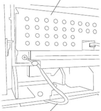 Grounding wireIf the jumper wire is NOT present, install the 40X7028 internal duplex grounding kit.This should only be done for machines with an installed internal duplex assembly.1. Check all connections on the system card assembly.2. Check all connections on the main drive motor assembly.3. Replace the main drive motor assembly. Go to “Output cover assembly removal” on page 4-54.4. Replace the system card assembly if problem remains. Go to “System card assembly removal” on page 4-76. Grounding wireIf the jumper wire is NOT present, install the 40X7028 internal duplex grounding kit.This should only be done for machines with an installed internal duplex assembly.1. Check all connections on the system card assembly.2. Check all connections on the main drive motor assembly.3. Replace the main drive motor assembly. Go to “Output cover assembly removal” on page 4-54.4. Replace the system card assembly if problem remains. Go to “System card assembly removal” on page 4-76. |
| 937.80 Main | drive motor assembly failureDriver over temp detection.Motor = type 0 | The main drive motor assembly may be faulty or has failed. | 1. Check all connections on the system card assembly.2. Check all connections on the main drive motor assembly.3. Replace the main drive motor assembly. Go to “Output cover assembly removal” on page 4-54.4. Replace the system card assembly if problem remains. Go to “System card assembly removal” on page 4-76. |
| 937.81 Main | drive motor assembly failureDriver over temp detection.Motor = type 1 | The main drive motor assembly may be faulty or has failed. | 1. Check all connections on the system card assembly.2. Check all connections on the main drive motor assembly.3. Replace the main drive motor assembly. Go to “Output cover assembly removal” on page 4-54.4. Replace the system card assembly if problem remains. Go to “System card assembly removal” on page 4-76. |
| 939.00 System card failure RIP-engine communication lost. | Replace the system card assembly.Go to “System card assembly removal” on page 4-76. | ||
| 940.00 System card failure LVPS zero-crossing test failed. Replace the system card assembly.Go to “System card assembly removal” on page 4-76. | |||
| 947.00 System card failure RAM test incomplete. Replace the system card assembly.Go to “System card assembly removal” on page 4-76. | |||
| 948.00 System card failure Pel clock check failed. Replace the system card assembly.Go to “System card assembly removal” on page 4-76. | |||
| 949.00 System card failure Delay line calibration failure. Replace the system card assembly.Go to “System card assembly removal” on page 4-76. | |||
| 950.xx NVRAM mismatch failure | Mismatch between system card EEPROM and operator panel mirror."xx" codes:00-29: mismatch between system and mirror30-60: mismatch between secure and system | Warning: When replacing any of the following components:Operator panel assembly (5230n/dn, 5350dn, and 5530dn)NVM card assembly (T656 only)System card assembly (All models)Only replace one component at a time. Replace the required component and perform a POR before replacing a second component listed above. If this procedure is not followed, the printer will be rendered inoperable. Never replace two or more of the components listed above without a POR after installing each one or the printer will be rendered inoperable.Never install and remove components listed above as a method of troubleshooting components. Once a component has been installed in a machine, it can not be used in another machine. It must be returned to the manufacturer.Go to NVRAM mismatch failure service check.See "NVRAM mismatch failure (950.00 through 950.29) service check" on page 2-148. | |
| 952.xx NVRAM failure A recoverable MVRAM Cyclic Redundancy Check (CRC) error occurred. | Power the machine off/on to reset the error condition. | ||
| 953.xx NVRAM failure The NVRAM chip has failed. Replace the operator panel door assembly (5230n/dn, 5350dn, and 5530dn).Go to "Operator panel door assembly removal (5230n/dn, 5350dn, and 5530dn)" on page 4-43 or replace the NVM card assembly (T656 only).Go to "NVM card assembly removal" on page 4-79. | |||
| 954.xx NVRAM failure | NVRAM chip failure with system card assembly. | Replace the system card assembly.Go to "System card assembly removal" on page 4-76. | |
| Error code or message | Error contents Description/Action Possible repair actions | ||
| 955.xx NVR | AM failure The Code ROM | or NAND flashfailed the Cyclic Redundancy Check (CRC) check or the NAND experienced an uncorrectible multi-bit failure. | Replace the system card assembly.Go to “System card assembly removal” on page 4-76. |
| 956.xx System card processor failure | The processor has failed on the system card assembly. | Replace the system card assembly.Go to “System card assembly removal” on page 4-76. | |
| 956.01 System card processor over temperature | The system card processor is over temperature or is damaged. | Replace the system card assembly.Go to “System card assembly removal” on page 4-76. | |
| 957.xx | System card ASIC failure | The ASIC has failed on the system card assembly. | Replace the system card assembly.Go to “System card assembly removal” on page 4-76. |
| 958.xx NAND failure | Printer has performed more than 100 "shift and reflash" operations as a result of ECC bit corrections | Replace the system card assembly.Go to “System card assembly removal” on page 4-76. | |
| 959.xx Print | cartridge authentication failure | The system card can not properly authenticate the print cartridge or the authentication process has failed. | Replace the system card assembly.Go to “System card assembly removal” on page 4-76. |
| 960.xx Memory failure | RAM Memory Error: RAM soldered on the card is bad | Replace the appropriate memory module. | |
| 961.xx Memory failure | RAM Memory Error: Slot 1 RAM is bad | Replace the appropriate memory module. | |
| 962.xx Memory failure | RAM Memory Error: Slot 2 RAM is bad | Replace the appropriate memory module. | |
| 963.xx Memory failure | RAM Memory Error: Slot 3 RAM is bad | Replace the appropriate memory module. | |
| 964.xx | Emulation failure The download EmulationCyclic Redundancy Check (CRC) detected a failure. | 1. Disable the Download Emulation. Program the download emulation into the firmware card again.2. Replace the system card assembly if problem remains.Go to “System card assembly removal” on page 4-76. | |
| 975.xx Network Error The system detected | unrecognizable network port | Replace the system card assembly.Go to “System card assembly removal” on page 4-76. | |
| 976.xx Network Error The system detected | unrecoverable software error in network port | Replace the system card assembly.Go to “System card assembly removal” on page 4-76. | |
| 978.xx Network Error The system detected | a bad checksum while programming network port | Replace the system card assembly.Go to “System card assembly removal” on page 4-76. | |
| 979.xx Network Error | The flash parts failed while programming a network port | Replace the system card assembly.Go to “System card assembly removal” on page 4-76. | |
| 980.00 Communication failure | The engine is experiencing unreliable communications to the paper port device. | Replace the system card assembly.Go to “System card assembly removal” on page 4-76. | |
| 981.00 Communication failure | The engine protocol violation detected by the paper port device. | Replace the system card assembly.Go to “System card assembly removal” on page 4-76. | |
| 982.00 Communication failure | Communications error detected by the paper port device. | Replace the system card assembly.Go to “System card assembly removal” on page 4-76. | |
| 982.01 Communication failure | Paper port communication device detected a validation failure. | Replace the system card assembly.Go to “System card assembly removal” on page 4-76. | |
| 982.02 Communication failure | Paper port communication device detected a framing error or the receive buffer overflowed. | Replace the system card assembly.Go to “System card assembly removal” on page 4-76. | |
| 982.03 Communication failure | Paper port communication device timed out during communication. | Replace the system card assembly.Go to “System card assembly removal” on page 4-76. | |
| 982.04 Output option communication failure. | An output option was not fully seated onto the printer or has been removed while the main power is turned on. | 1. Turn the main power off.2. Remove and reinstall the output option.3. Turn the main power back on.4. Check all output option interface connections if problem remains. | |
| 982.06 Paperport failure Paper port prioritizer error.Option device message was not read by the prioritizer. | Replace the system card assembly.Go to “System card assembly removal” on page 4-76. | ||
| 982.07 Too many options installed | Exceeded the maximum number of input or output options. | Remove the appropriate input or output options. | |
| 982.11 Paperport failure Command response error on the paper port. Response is too large for the communications buffer. | Replace the system card assembly.Go to “System card assembly removal” on page 4-76. | ||
| 982.12 Paperport failure Bad bottom trunk on the paper port. | Replace the system card assembly.Go to “System card assembly removal” on page 4-76. | ||
| 982.13 Hot plug failure The printer has detected a hot plug of an optional device.Low-level error on paper port. | Power the machine off/on after all options are installed. | ||
| 983.00 Communication failure | Invalid command received by the paper port device. | Replace the system card assembly.Go to “System card assembly removal” on page 4-76. | |
| 984.00 Communication failure | Invalid command parameter received by the paper port device. | Replace the system card assembly.Go to “System card assembly removal” on page 4-76. | |
| Error code or message | Error contents Description/Action Possible repair actions | ||
| 985.01 Service engine RFID communications | Generic hardware error 1. Check the RFID firmware card, RFID interface card, RFID cable, and RFID option for correct installation. Go to “High capacity input tray (HCIT) pick arm bracket assembly removal” on page 4-131.2. Replace the RFID UHF option.Note: There can be no other connectivity options installed on printers that have the RFID UHF option installed. If any connectivity option is installed (other than the RFID interface card), a 985.xx error will occur | ||
| 985.02 Service engine RFID communications | Printer having problems communicating with radio | 1. Check the RFID firmware card, RFID interface card, RFID cable, and RFID option for correct installation. Go to “High capacity input tray (HCIT) pick arm bracket assembly removal” on page 4-131.2. Replace the RFID UHF option.Note: There can be no other connectivity options installed on printers that have the RFID UHF option installed. If any connectivity option is installed (other than the RFID interface card), a 985.xx error will occurs | |
| 985.03 Service engine RFID communications | Radio having problems communicating with printer | 1. Check the RFID firmware card, RFID interface card, RFID cable, and RFID option for correct installation. Go to “High capacity input tray (HCIT) pick arm bracket assembly removal” on page 4-131.2. Replace the RFID UHF option.Note: There can be no other connectivity options installed on printers that have the RFID UHF option installed. If any connectivity option is installed (other than the RFID interface card), a 985.xx error will occur | |
| 985.04 Service engine RFID communications | Radio communications are out of sync | 1. Check the RFID firmware card, RFID interface card, RFID cable, and RFID option for correct installation. Go to “High capacity input tray (HCIT) pick arm bracket assembly removal” on page 4-131.2. Replace the RFID UHF option.Note: There can be no other connectivity options installed on printers that have the RFID UHF option installed. If any connectivity option is installed (other than the RFID interface card), a 985.xx error wll occur | |
| 985.05 Service engine RFID communications | Internal radio problem 1. Check the RFID firmware card, RFID interface card, RFID cable, and RFID option for correct installation. Go to “High capacity input tray (HCIT) pick arm bracket assembly removal” on page 4-131.2. Replace the RFID UHF option.Note: There can be no other connectivity options installed on printers that have the RFID UHF option installed. If any connectivity option is installed (other than the RFID interface card), a 985.xx error will occur | ||
| 985.06 Service engine RFID communications | Radio reported antenna problem | 1. Check the RFID firmware card, RFID interface card, RFID cable, and RFID option for correct installation. Go to “High capacity input tray (HCIT) pick arm bracket assembly removal” on page 4-131.2. Replace the RFID UHF option.Note: There can be no other connectivity options installed on printers that have the RFID UHF option installed. If any connectivity option is installed (other than the RFID interface card), a 985.xx error will occurs | |
| Error code or message | Error contents Description/Action Possible repair actions | ||
| 985.07 Service engine RFID communications | Antenna is disconnected 1. Check the RFID firmware card, RFID interface card, RFID cable, and RFID option for correct installation. Go to “High capacity input tray (HCIT) pick arm bracket assembly removal” on page 4-131.2. Replace the RFID UHF option.Note: There can be no other connectivity options installed on printers that have the RFID UHF option installed. If any connectivity option is installed (other than the RFID interface card), a 985.xx error will occur | ||
| 990.00 Output option equipment check. | Output option rear door not fully closed. | Close the rear door on all output options. | |
| 990.02 Paperport failure Invalid paperport parameter Replace the system card | |||
| 990.03 Paperport failure Invalid paperport protocol Replace the system card | |||
| 990.04 Paperport failure Unsupported paperport command | Replace the system card assembly.Go to “System card assembly removal” on page 4-76. | ||
| 990.06 Paperport failure Unknown page supervisor state | Replace the system card assembly.Go to “System card assembly removal” on page 4-76. | ||
| 990.09 Paperport failure Paperport framing error Replace the system card | assembly.Go to “System card assembly removal” on page 4-76. | ||
| 990.10 Paperport failure Paperport overrun error Replace the system card | assembly.Go to “System card assembly removal” on page 4-76. | ||
| 990.11 Paperport failure Paperport parity error Replace the system card | assembly.Go to “System card assembly removal” on page 4-76. | ||
| 990.12 Paperport failure Paper port other paper port error | Replace the system card assembly.Go to “System card assembly removal” on page 4-76. | ||
| 990.13 Paperport failure Paperport encountered multiple communication error | Replace the system card assembly.Go to “System card assembly removal” on page 4-76. | ||
| 990.14 Paperport failure Invalid paperport echo Replace the system card | assembly.Go to “System card assembly removal” on page 4-76. | ||
| 990.51 HCIT tray lift motor PWM underflow error | The HCIT tray lift motor does not operate at the specified speed reported by tray x | 1. Check for obstruction in the HCIT tray lift area.2. Check the connections on the HCIT tray lift motor assembly for proper connection.3. Replace the HCIT tray lift motor drive motor assembly if problem remains. Go to “High capacity input tray (HCIT) tray lift drive motor assembly removal” on page 4-126. | |
| 990.53 HCIT tray lift motor ramp error | The HCIT tray lift motor does not reach the specified speed at the specified time. | 1. Check for obstruction in the HCIT tray lift area.2. Check the connections on the HCIT tray lift motor assembly for proper connection.3. Replace the HCIT tray lift drive motor assembly if problem remains. Go to “High capacity input tray (HCIT) tray lift drive motor assembly removal” on page 4-126. | |
| Error code or message | Error contents Description/Action Possible repair actions | ||
| 990.54 HCIT | tray lift motor lost encoder failure | The HCIT tray lift motor is not reporting pulses back to the engine. | 1. Check for obstruction in the HCIT tray lift area.2. Check the connections on the HCIT tray lift motor assembly for proper connection.3. Replace the HCIT tray lift drive motor assembly if problem remains. Go to “High capacity input tray (HCIT) tray lift drive motor assembly removal” on page 4-126 |
| 990.90 Sensor connection failure | Hardware error (sensors are not plugged on the board) | Replace all connections on the system card assembly. | |
| 991.00 System card failure Device system card failed basic assurance test. | Replace the system card assembly.Go to “System card assembly removal” on page 4-76. | ||
| 991.05 Checksum failure Bad checksum Replace the system card | assembly.Go to “System card assembly removal” on page 4-76. | ||
Service checks
Sensor (input) service check
| Step | Check Yes No | ||
| 1 | Check the sensor (input) for damage.Is the above component free from damage? | Go to step 2. Replace the sensor (input).Go to “Sensor (input) removal” on page 4-71. | |
| 2 | Enter the diagnostic modeSelect Base sensor testObserve the line item “input”Does the display on the operator panel, change every time the sensing area of the above sensor is interrupted or blocked. | The sensor is working properly | Go to step 2. |
| 3 | Check the above sensor for proper connection.Is the above sensor connected properly? | Replace the Sensor (input).Go to “Sensor (input) removal” on page 4-71. | Replace the connection. |
Sensor (fuser output) service check
| Step | Check Yes No | ||
| 1 | Check the sensor (fuser output) for damage.Is the above component free from damage? | Go to step 2. Replace fuser unit assembly.Go to “Fuser unit assembly removal” on page 4-22. | |
| 2 | Enter the diagnostic modeSelect Base sensor testObserve the line item “exit”Does the display on the operator panel, change every time the sensing area of the above sensor is interrupted or blocked. | The sensor is working properly | Go to step 2. |
| 3 | Check the above sensor for proper connection.Is the above sensor connected properly? | Replace the fuser unit assembly.Go to “Fuser unit assembly removal” on page 4-22. | Replace the connection. |
Sensor (narrow media) service check
| Step | Check Yes No | ||
| 1 | Check the sensor (narrow media) for damage.Is the above component free from damage? | Go to step 2. Replace the fuser unit assembly.Go to “Fuser unit assembly removal” on page 4-22. | |
| 2 | Enter the diagnostic mode.Select Base sensor test.Observe the line item “narrow media”.Does the display on the operator panel, change every time the sensing area of the above sensor is interrupted or blocked. | The sensor is working properly | Go to step 2. |
| 3 | Check the above sensor for proper connection.Is the above sensor connected properly? | Replace fuser unit assembly.Go to “Fuser unit assembly removal” on page 4-22. | Replace the connection. |
Sensor (duplex input) service check
| Step | Check Yes No | ||
| 1 | Check the sensor (duplex input) for damage.Is the above component free from damage? | Go to step 2. Replace the sensor (duplex input).Go to “Sensor (duplex input) removal (5350dn, 5530dn, and T656)” on page 4-69. | |
| 2 | Enter the diagnostic mode.Select Duplex sensor tests.Select Sensor test.Observe the line item “input”.Does the display on the operator panel, change every time the sensing area of the above sensor is interrupted or blocked. | The sensor is working properly | Go to step 2. |
| 3 | Check the above sensor for proper connection.Is the above sensor connected properly? | Replace the duplex input sensor assembly (internal duplex only).Go to “Duplex input sensor assembly removal (5350dn, 5530dn, and T656)” on page 4-19.or replace the external duplex unit assembly (external duplex only). | Replace the connection. |
Sensor (duplex input) service check (external duplex only)
| Step | Check Yes No | ||
| 1 | Check the sensor (duplex input) for damage.Is the above component free from damage? | Go to step 2. Replace the external duplex unit assembly. | |
| 2 | Enter the diagnostic modeSelect Duplex sensor testsSelect Sensor testObserve the line item “input”Does the display on the operator panel, change every time the sensing area of the above sensor is interrupted or blocked. | The sensor is working properly | Go to step 2. |
| 3 | Check the above sensor for proper connection.Is the above sensor connected properly? | Replace the external duplex unit assembly. | Replace the connection. |
Sensor (duplex exit) service check (external duplex only)
| Step | Check Yes No | ||
| 1 | Check the sensor (duplex exit) for damage.Is the above component free from damage? | Go to step 2. Replace the external duplex unit assembly. | |
| 2 | Enter the diagnostic modeSelect Duplex sensor testsSelect Sensor testObserve the line item “exit”Does the display on the operator panel, change every time the sensing area of the above sensor is interrupted or blocked. | The sensor is working properly | Go to step 2. |
| 3 | Check the above sensor for proper connection.Is the above sensor connected properly? | Replace the external duplex unit assembly. | Replace the connection. |
Sensor (pass through) service check
| Step | Check Yes No | ||
| 1 1. | Enter the diagnostic mode2. Select Input tray tests3. Select Sensor test4. Select the appropriate tray number5. Observe the line item “pass through” for the appropriate media trayDoes the display on the operator panel, change every time the sensing area of the above sensor is interrupted or blocked. | The sensor is working properly | Go to step 2. |
| 2 | Check the above sensor for proper connection.Is the above sensor connected properly? | Replace the sensor (pass through).Go to “250-sheet controller card assembly removal” on page 4-107. | Replace the connection. |
Sensor (envelope feeder empty) service check
| Step | Check Yes No | ||
| 1 1. | Enter the diagnostic mode2. Select Input tray tests3. Select Sensor test4. Select Envelope feeder5. Observe the line item “empty”Does the display on the operator panel, change every time the sensing area of the above sensor is interrupted or blocked. | The sensor is working properly | Go to step 2. |
| 2 | Check the above sensor for proper connection.Is the above sensor connected properly? | Replace the envelope feeder. | Replace the connection. |
Sensor (input) late jam service check.
Use this procedure for the following jams:
• 200.07 • 230.04 • 230.06 • 237.00 • 239.11
• 241.06 • 214.10 • 241.11 • 241.12 • 241.14
• 241.15 • 241.16 • 241.18 • 242.09 • 250.03
• 250.06 • 250.07 • 250.08 • 250.09 • 250.10
• 250.11 • 260.07 • 260.10 • 260.11 • 260.12
• 260.14 • 260.15 • 260.16
| Step | Check Yes No | ||
| 1 | Check the media size setup and tray guides for all media trays.Does the media size, in use, match the size set for all media trays? | Go to step 2. Replace the media, or change the media size setup. | |
| 2 | Check the media trays for overfilling.Are any of the media trays overfilled? | Remove any excess new media. | Go to step 3 |
| 3 | Check the media condition in all media trays.Is any of the media in any of the media trays crumpled or damaged? | Replace the damaged media with new. | Go to step 4. |
| 4 | Check the media tray pass through areas for obstructions.Are the pass through areas in all the media trays free from obstructions? | Go to step 5. Remove obstructions. | |
| 5 | Check media origination.Did the media originate from the MPF? | Go to step 6. Go to step 8. | |
| 6 | Check the MPF pick roll assembly.Is the above component free of excess wear and contamination? | Go to step 7. Clean or replace the MPF pick roll assembly.Go to “MPF pick roll assembly removal” on page 4-37. | |
| 7 | Perform a MPF print test and check the MPF pick solenoid for proper operation.Does the above component operate properly? | Go to step 17. Replace the MPF pick solenoid.Go to “MPF pick solenoid assembly removal” on page 4-38. | |
| 8 | Check media origination.Did the media originate from the internal duplex? | Go to step 9 Go to step 13 | |
| 9 | Check the internal duplex media path for obstructions.Is the above component free from obstructions? | Go to step 10 Remove obstructions. | |
| 10 | Check the sensor (duplex input) for proper operation.1. Enter the diagnostic mode2. Select Duplex tests3. Select sensor test4. Observe the line item “input”Does the display on the operator panel, change every time the sensing area of the above sensor is interrupted or blocked. | Go to step 12. Go to step 11. | |
| 11 | Check the above sensor for proper connection.Is the above sensor connected properly? | Replace the Sensor (duplex input).Go to “Sensor (duplex input) removal (5350dn, 5530dn, and T656)” on page 4-69. | Replace the connection. |
| 12 | Perform a print test and check the duplex drive motor assembly for proper operation.Does the above component operate properly? | Go to step 17. Replace the duplex drive motor assembly.Go to “Duplex drive motor assembly removal (5350dn, 5530dn, and T656)” on page 4-18. | |
| 13 | Check media origination.Did the media originate from the external duplex? | Go to step 14. Go to step 16. | |
| 14 | Check the sensor (duplex input) for proper operation.1. Enter the diagnostic mode.2. Select Duplex tests.3. Select sensor test.4. Observe the line item “input”.Does the display on the operator panel, change every time the sensing area of the above sensor is interrupted or blocked. | Go to step 15. Replace the external duplex assembly. | |
| 15 | Check the sensor (duplex exit) for proper operation.1. Enter the diagnostic mode.2. Select Duplex tests.3. Select sensor test.4. Observe the line item “exist”.Does the display on the operator panel, change every time the sensing area of the above sensor is interrupted or blocked. | Go to step 17. Replace the external duplex assembly. | |
| 16 | Check the two pick roll assemblies in the media tray being picked from.Are the above components free of excess wear and contamination? | Go to step 17. Clean or replace the pick roll assembly.Go to “Pick roll assembly removal” on page 4-57. | |
| 17 | Check the aligner assembly for obstructions.Is the above component free from obstructions? | Go to step 18. Remove obstructions. | |
| 18 | Check the sensor (input) for proper operation.1. Enter the diagnostic mode.2. Select Base sensor test.3. Observe the line item “input”.Does the display on the operator panel, change every time the sensing area of the above sensor is interrupted or blocked. | The sensor is working properly.Go to step 20. | Go to step 19. |
| 19 | Check the above sensor for proper connection.Is the above sensor connected properly? | Replace the Sensor (input).Go to “Sensor (input) removal” on page 4-71. | Replace the connection. |
| 20 | Perform a print test and check the pick arm assembly.Is the media properly picked and advanced out of the media tray? | Go to step 21. Replace the pick arm assembly. Go to “Operator panel door assembly removal (T656)” on page 4-49. | |
| 21 | Perform a print test and check the main motor assembly.Is the media properly transported and able to reach the sensor (input)? | Go to step 22. Replace the main drive motor assembly. Go to “Output cover assembly removal” on page 4-54. | |
| 22 | Perform a print test.Does the problem remain? | Contact next highest level of tech support. | Problem solved. |
Sensor (input) lingering jam service check.
Use this procedure for the following jams:
• 200.01 • 200.02 • 200.17 • 200.18 • 200.19
• 200.27 • 200.28 • 200.29 • 200.37 • 200.38
• 200.39 • 200.47 • 200.48 • 200.49 • 200.57
• 200.58 • 200.59
| Step | Check Yes No | ||
| 1 | Check the media size setup and tray guides for all media trays.Does the media size, in use, match the size set for all media trays? | Go to step 2. Replace the media, or change the media size setup. | |
| 2 | Check the fuser unit assembly for obstructions.Is the above component free of obstructions? | Remove obstructions. | Go to step 3. |
| 3 | Check the fuser unit assembly for excess wear and damage.Is the above component free of excess wear and damage? | Go to step 4. Replace the fuser unit assembly.Go to “Fuser unit assembly removal” on page 4-22. | |
| 4 | Check the sensor (input) for proper operation.Enter the diagnostic modeSelect Base sensor testObserve the line item “input”Does the display on the operator panel, change every time the sensing area of the above sensor is interrupted or blocked. | Go to step 6. Go to step 5. | |
| 5 | Check the above sensor for proper connection.Is the above sensor connected properly? | Replace the sensor (input).Go to “Sensor (input) removal” on page 4-71. | Replace the connection. |
| 6 | Check the sensor (fuser output) for proper operation.1. Enter the diagnostic mode2. Select Base sensor test3. Observe the line item “exit”Caution: The area around the actuator is very hot. Allow the fuser area to cool before proceeding.Does the display on the operator panel, change every time the sensing area of the above sensor is interrupted or blocked? | Go to step 8. Go to | step 7. |
| 7 | Check the above sensor for proper connection.Is the above sensor connected properly? | Replace the fuser unit assembly.Go to “Fuser unit assembly removal” on page 4-22. | Replace the connection. |
| 8 | Perform a print test and check the main motor assembly.Is the media properly transported and able to reach the sensor (fuser output)? | Replace the main drive motor assembly.Go to “Output cover assembly removal” on page 4-54. | Replace the connection. |
| 9 | Check the aligner assembly for obstructions.Is the above component free from obstructions? | Go to step 10. Remove obstructions. | |
| 10 | Perform a print test.Does the problem remain? | Contact next highest level of tech support. | Problem solved. |
Sensor (input) early jam service check
Use this procedure for the following jams:
• 200.04 • 200.06 • 200.08 • 200.14 • 200.33
| Step | Check Yes No | ||
| 1 | Check media origination.Did the media originate from the MPF? | Go to step 2. Go to | step 5. |
| 2 | Check the MPF pick roll assembly.Is the above component free of excess wear and contamination? | Go to step 3. Clean | or replace the MPF pick roll assembly.Go to “MPF pick roll assembly removal” on page 4-37. |
| 3 | Perform a MPF print test and check the MPF pick solenoid for proper operation.Does the above component operate properly? | Go to step 4. Replace the MPF pick solenoid.Go to “MPF pick solenoid assembly removal” on page 4-38. | |
| 4 | Check the MPF lift plate assembly for damage.Is the above component free from damage? | Go to step 5. Replace the MPF lift plate assembly.Go to “MPF lift plate assembly removal” on page 4-36. | |
| 5 | Check all the media trays for proper media installation.Is the media properly installed in all the media trays? | Go to step 6. Remove and properly re-install the media. | |
| 6 | Check all of the media trays and the media path for partially fed media.Are the media trays and the media path free from any partially fed pieces of media? | Go to step 7. Remove any pre-staged or jammed media. | |
| 7 | Check the sensor (input) for proper operation.1. Enter the diagnostic mode2. Select Base sensor test3. Observe the line item “input”Does the display on the operator panel, change every time the sensing area of the above sensor is interrupted or blocked. | Go to step 9. Go to step 8. | |
| 8 | Check the above sensor for proper connection.Is the above sensor connected properly? | Replace the Sensor (input).Go to “Sensor (input) removal” on page 4-71. | Replace the connection. |
| 9 | Perform a print test.Does the problem remain? | Contact next highest level of tech support. | Problem solved. |
Sensor (input) static jam service check
Use this procedure for the following jams:
• 200.13
| Step | Check Yes No | ||
| 1 | Check the media path for partially fed or jammed media.Is the media path free from partially fed or jammed media? | Go to step 2. Remove any pre-staged or jammed media. | |
| 2 | Check the sensor (input) for proper operation.1. Enter the diagnostic mode2. Select Base sensor test3. Observe the line item “input”Does the display on the operator panel, change every time the sensing area of the above sensor is interrupted or blocked. | Go to step 4. Go to step 3. | |
| 3 | Check the above sensor for proper connection.Is the above sensor connected properly? | Replace the Sensor (input).Go to “Sensor (input) removal” on page 4-71. | Replace the connection. |
| 4 | Perform a print test.Does the problem remain? | Contact next highest level of tech support. | Problem solved. |
Sensor (fuser output) late jam service check.
Use this procedure for the following jams:
• 201.02 • 201.07 • 201.27 • 201.32 • 201.50
• 201.52 • 201.57 • 201.75 • 201.77 • 201.82
| Step | Check Yes No | ||
| 1 | Check the media size setup and tray guides for all media trays.Does the media size, in use, match the size set for all media trays? | Go to step 2. Replace the media, or change the media size setup. | |
| 2 | Check all the media trays for proper media installation.Is the media properly installed in all the media trays? | Go to step 3. Remove and properly re-install the media. | |
| 3 | Check the fuser unit assembly for damage and life expiration.Is the above component damaged or has it exceeded life? | Replace the fuser unit assembly.Go to “Fuser unit assembly removal” on page 4-22. | Go to step 4. |
| 4 | Check the fuser unit assembly for obstructions.Is the above component free from obstructions? | Go to step 5. Remove obstructions. | |
| 5 | Check the sensor (fuser output) for proper operation.1. Enter the diagnostic mode2. Select Base sensor tests3. Observe the line item “output”Does the display on the operator panel, change every time the sensing area of the above sensor is interrupted or blocked. | Go to step 7. Go to | step 6. |
| 6 | Check the above sensor for proper connection.Is the above sensor connected properly? | Replace the fuser unit assembly.Go to “Fuser unit assemblyremoval” on page 4-22. | Replace the connection. |
| 7 | Check the aligner assembly for obstructions.Is the above component free from obstructions? | Go to step 8. Remove | obstructions. |
| 8 | Check the transfer roll assembly for damage.Is the above component free from damage? | Go to step 9. Replace the transfer roll assembly.Go to “Transfer roll assemblyremoval” on page 4-80. | |
| 9 | Perform a print test and check the main motor assembly.Is the media properly transported and able to reach the sensor (fuser output)? | Go to step 10. Replace the main drive motor assembly.Go to “Output cover assemblyremoval” on page 4-54. | |
| 10 | Perform a print test.Does the problem remain? | Contact next highest level of tech support. | Problem solved. |
Sensor (fuser output) lingering jam service check.
Use this procedure for the following jams:
• 202.01 • 202.02 • 202.07 • 202.10 • 202.11
• 202.12 • 202.26 • 202.27 • 202.32 • 202.34
• 202.35 • 202.36 • 202.37 • 202.51 • 202.52
• 202.57 • 202.59 • 202.60 • 202.61 • 202.62
• 202.76 • 202.77 • 202.82 • 202.84 • 202.85
· 202.86 · 202.87
| Step | Check Yes No | ||
| 1 | Check the media size setup and tray guides for all media trays.Does the media size, in use, match the size set for all media trays? | Go to step 2. Replace the media, or change the media size setup. | |
| 2 | Check all the media trays for proper media installation.Is the media properly installed in all the media trays? | Go to step 3. Remove and properly re-install the media. | |
| 3 | Check the door assembly, rear.Is the above component properly closed? | Go to step 4. Open then properly close the door assembly, rear. | |
| 4 | Check the fuser unit assembly for damage and life expiration.Is the above component damaged or has it exceeded life? | Replace the fuser unit assembly.Go to “Fuser unit assembly removal” on page 4-22. | Go to step 5. |
| 5 | Check the sensor (fuser output) for proper operation.1. Enter the diagnostic mode2. Select Base sensor tests3. Observe the line item “output”Does the display on the operator panel, change every time the sensing area of the above sensor is interrupted or blocked. | Go to step 7. Go to step 6. | |
| 6 | Check the above sensor for proper connection.Is the above sensor connected properly? | Replace the fuser unit assembly.Go to “Fuser unit assembly removal” on page 4-22. | Replace the connection. |
| 7 | Check the redrive assembly for damage.Is the above component free from damage? | Go to step 8. Replace the redrive assembly.Go to “Option removals” on page 4-85. | |
| 8 | Perform a print test and check the redrive motor assembly for proper operation.Does the above component operate properly? | Go to step 9. Replace the redrive motor assembly.Go to “Redrive assembly removal” on page 4-63. | |
| Step Check Yes No | |||
| 9 | Perform a print test.Does the problem remain? | Contact next highest level of tech support. | Problem solved. |
Sensor (fuser output) static jam service check
Use this procedure for the following jams:
• 202.06 • 202.13 • 202.31 • 202.38 • 202.56
• 202.63 • 202.81 • 202.88
| Step | Check Yes No | ||
| 1 | Check the media path for partially fed or jammed media.Is the media path free from partially fed or jammed media? | Go to step 2. Remove any pre-staged or jammed media. | |
| 2 | Check the sensor (fuser output) for proper operation.1. Enter the diagnostic mode2. Select Base sensor test3. Observe the line item “input”Does the display on the operator panel, change every time the sensing area of the above sensor is interrupted or blocked. | Go to step 4. Go to step 3. | |
| 3 | Check the above sensor for proper connection.Is the above sensor connected properly? | Replace the fuser unit assembly.Go to “Fuser unit assembly removal” on page 4-22. | Replace the connection. |
| 4 | Perform a print test.Does the problem remain? | Contact next highest level of tech support. | Problem solved. |
Sensor (narrow media) late jam service check.
Use this procedure for the following jams:
• 201.04 • 201.06 • 201.29 • 201.31 • 201.54
• 201.56 • 201.79 • 201.81
| Step | Check Yes No | ||
| 1 | Check the media size setup and tray guides for all media trays.Does the media size, in use, match the size set for all media trays? | Go to step 2. Replace the media, or change the media size setup. | |
| 2 | Check all the media trays for proper media installation.Is the media properly installed in all the media trays? | Go to step 3. Remove | and properly re-install the media. |
| 3 | Check the fuser unit assembly for damage and life expiration.Is the above component damaged or has it exceeded life? | Replace the fuser unit assembly.Go to “Fuser unit assembly removal” on page 4-22. | Go to step 4. |
| 4 | Check the fuser unit assembly for obstructions.Is the above component free from obstructions? | Go to step 5. Remove | obstructions. |
| 5 | Check the sensor (narrow media) for proper operation.1. Enter the diagnostic mode2. Select Base sensor tests3. Observe the line item “output”Does the display on the operator panel, change every time the sensing area of the above sensor is interrupted or blocked. | Go to step 7. Go to | step 6. |
| 6 | Check the above sensor for proper connection.Is the above sensor connected properly? | Replace the fuser unit assembly.Go to “Fuser unit assembly removal” on page 4-22. | Replace the connection. |
| 7 | Check the aligner assembly for obstructions.Is the above component free from obstructions? | Go to step 8. Remove | obstructions. |
| 8 | Check the transfer roll assembly for damage.Is the above component free from damage? | Go to step 9. Replace the transfer roll assembly.Go to “Transfer roll assembly removal” on page 4-80. | |
| 9 | Perform a print test and check the main motor assembly.Is the media properly transported and able to reach the sensor (fuser output)? | Go to step 10. Replace the main drive motor assembly.Go to “Output cover assembly removal” on page 4-54. | |
| Step Check Yes No | |||
| 10 | Perform a print test.Does the problem remain? | Contact next highest level of tech support. | Problem solved. |
Sensor (narrow media) static jam service check
Use this procedure for the following jams:
• 202.03 • 202.13 • 202.28 • 202.38 • 202.53
• 202.63 • 202.78 • 202.88
| Step | Check Yes No | ||
| 1 | Check the media path for partially fed or jammed media.Is the media path free from partially fed or jammed media? | Go to step 2. Remove any pre-staged or jammed media. | |
| 2 | Check the sensor (narrow media) for proper operation.Enter the diagnostic modeSelect Base sensor testObserve the line item “input”Does the display on the operator panel, change every time the sensing area of the above sensor is interrupted or blocked. | Go to step 4. Go to step 3. | |
| 3 | Check the above sensor for proper connection.Is the above sensor connected properly? | Replace the fuser unit assembly.Go to “Fuser unit assembly removal” on page 4-22. | Replace the connection. |
| 4 | Perform a print test.Does the problem remain? | Contact next highest level of tech support. | Problem solved. |
Sensor (duplex input) late jam service check.
Use this procedure for the following jams:
• 230.02 • 231.00
| Step | Check Yes No | ||
| 1 | Check the door assembly, rear.Is the above component properly closed? | Go to step 2. Open | thenproperly close thedoor assembly,rear. |
| 2 | Check the fuser access door.Is the above component properly closed? | Go to step 3. Open | thenproperly close thefuser access door. |
| 3 | Check media origination.Did the media originate from the internal duplex? | Go to step 4 Go to step 10 | |
| 4 | Check the internal duplex media path for obstructions.Is the above component free from obstructions? | Go to step 5 Removeobstructions. | |
| 5 | Check the redrive assembly for damage.Is the above component free from damage? | Go to step 6 Replace theredrive assembly.Go to “Optionremovals” onpage 4-85. | |
| 6 | Perform a print test and check the redrive motor assemblyfor proper operation.Does the above component operate properly? | Go to step 7. Replace theredrive motorassembly.Go to “Redriveassemblyremoval” onpage 4-63. | |
| 7 | Perform a print test and check the duplex drive motorassembly for proper operation.Does the above component operate properly? | Go to step 8 Replace theduplex drive motorassembly.Go to “Duplexdrive motorassemblyremoval (5350dn,5530dn, andT656)” onpage 4-18. | |
| 8 | Check the sensor (duplex input) for proper operation.1. Enter the diagnostic mode2. Select Duplex tests3. Select sensor test4. Observe the line item “input”Does the display on the operator panel, change every timethe sensing area of the above sensor is interrupted orblocked. | Go to step 10. Go to step 9. | |
| 9 | Check the above sensor for proper connection. Replace theIs the above sensor connected properly? | Replace theSensor (duplexinput).Go to “Sensor(duplex input)removal (5350dn,5530dn, andT656)” onpage 4-69. | connection. |
| 10 | Perform a print test and check the duplex drive motor assembly for proper operation.Does the above component operate properly? | Go to step 14. Replace the duplex drive motor assembly.Go to “Duplex drive motor assembly removal (5350dn, 5530dn, and T656)” on page 4-18. | |
| 11 | Check the external duplex media path for obstructions.Is the above component free from obstructions? | Go to step 12 Remove obstructions. | |
| 12 | Check the external duplex unit assembly for proper installation.Is the above component properly installed? | Go to step 13. Remove then properly re-install the external duplex unit assembly. | |
| 13 | Check the sensor (duplex input) for proper operation.1. Enter the diagnostic mode2. Select Duplex tests3. Select sensor test4. Observe the line item “input”.Does the display on the operator panel, change every time the sensing area of the above sensor is interrupted or blocked. | Go to step 14. Replace the external duplex assembly. | |
| 14 | Perform a print test using the duplex.Does the problem remain? | Contact next highest level of tech support. | Problem solved. |
Sensor (duplex input) lingering jam service check.
Use this procedure for the following jams:
• 230.01 • 230.05 • 232.00
| Step | Check Yes No | ||
| 1 | Check media origination.Did the media originate from the internal duplex? | Go to step 2 Go to step 7 | |
| 2 | Check the internal duplex media path for obstructions.Is the above component free from obstructions? | Go to step 3 Removeobstructions. | |
| 3 | Check the duplex guide assembly, front for damage.Is the above component free from damage? | Go to step 4. Replace theduplex guideassembly, front.Go to “Duplexguide assembly,front removal(5350dn, 5530dn,and T656)” onpage 4-20. | |
| 4 | Check the sensor (duplex input) for proper operation.1. Enter the diagnostic mode.2. Select Duplex tests.3. Select sensor test.4. Observe the line item “input”.Does the display on the operator panel, change every time the sensing area of the above sensor is interrupted or blocked. | Go to step 6. Go to step 5. | |
| 5 | Check the above sensor for proper connection.Is the above sensor connected properly? | Replace the sensor (duplex input).Go to “Sensor (duplex input) removal (5350dn, 5530dn, and T656)” on page 4-69. | Replace the connection. |
| 6 | Check the aligner assembly for obstructions.Is the above component free from obstructions? | Go to step 7. Remove obstructions. | |
| 7 | Check the external duplex media path for obstructions.Is the above component free from obstructions? | Go to step x Remove obstructions. | |
| 8 | Check the external duplex unit assembly for proper installation.Is the above component properly installed? | Go to step 9. Remove then properly re-install the external duplex unit assembly. | |
| 9 | Check the sensor (duplex input) for proper operation.1. Enter the diagnostic mode.2. Select Duplex tests.3. Select sensor test.4. Observe the line item “input”.Does the display on the operator panel, change every time the sensing area of the above sensor is interrupted or blocked. | Go to step 10. Replace the external duplex assembly. | |
| 10 | Perform a print test using the duplex.Does the problem remain? | Contact next highest level of tech support. | Problem solved. |
Sensor (duplex input) static jam service check.
Use this procedure for the following jams:
• 230.13 • 238.01 • 238.03 • 238.05 • 238.07
| Step | Check Yes No | ||
| 1 | Check media origination.Did the media originate from the internal duplex? | Go to step 2 Go to step 5 | |
| 2 | Check the media path for partially fed or jammed media.Is the media path free from partially fed or jammed media? | Go to step 3. Remove any pre-staged or jammed media. | |
| 3 | Check the sensor (duplex input) for proper operation.1. Enter the diagnostic mode.2. Select Duplex tests.3. Select sensor test.4. Observe the line item “input”.Does the display on the operator panel, change every time the sensing area of the above sensor is interrupted or blocked. | Go to step 7. Go to step 4. | |
| 4 | Check the above sensor for proper connection.Is the above sensor connected properly? | Replace the sensor (duplex input).Go to “Sensor (duplex input) removal (5350dn, 5530dn, and T656)” on page 4-69. | Replace the connection. |
| 5 | Check the media path for partially fed or jammed media. Go is the media path free from partially fed or jammed media? | to step 6. Remove any pre-staged or jammed media. | |
| 6 | Check the sensor (duplex input) for proper operation.1. Enter the diagnostic mode.2. Select Duplex tests.3. Select sensor test.4. Observe the line item “input”.Does the display on the operator panel, change every time the sensing area of the above sensor is interrupted or blocked. | Go to step 7. Replace the external duplex assembly. | |
| 7 | Perform a print test using the duplex.Does the problem remain? | Contact next highest level of tech support. | Problem solved. |
Sensor (pass through) late jam service check
Use this procedure for the following jams:
• 242.02 • 242.03 • 242.04 • 242.05 • 242.06
• 242.10 • 242.16 • 242.37 • 243.02 • 243.03
• 243.04 • 243.04 • 243.05 • 243.06 • 243.10
• 243.16 • 243.37 • 244.02 • 244.03 • 244.04
• 244.05 • 244.06 • 244.10 • 244.16 • 244.37
• 245.02 • 245.03 • 245.04 • 245.05 • 245.06
• 245.10 • 245.13 • 245.16 • 245.37
| Step | Check Yes No | ||
| 1 | Check the media size setup and tray guides for all media trays.Does the media size, in use, match the size set for all media trays? | Go to step 2. Replace the media, or change the media size setup. | |
| 2 | Check the media trays for overfilling.Are any of the media trays overfilled? | Remove any excess new media. | Go to step 3 |
| 3 | Check the media condition in all media trays.Is any of the media in any of the media trays crumpled or damaged? | Replace the damaged media with new. | Go to step 4. |
| 4 | Check the media tray pass through areas for obstructions.Are the pass through areas in all the media trays free from obstructions? | Go to step 5. Remove obstructions. | |
| 5 | Check the two pick roll assemblies in the media tray being picked from.Are the above components free of excess wear and contamination? | Go to step 6. Clean or replace the pick roll assembly.Go to “Pick roll assembly removal” on page 4-57 | |
| 6 | Check the appropriate media tray sensor (pass through) for proper operation.Enter the diagnostic modeSelect Input tray testsSensor testSelect the appropriate tray numberObserve the line item “pass through” for the appropriate media trayDoes the display on the operator panel, change every time the sensing area of the above sensor is interrupted or blocked. | Go to step 7. Go to step 6. | |
| 7 | Check the above sensor for proper connection.Is the above sensor connected properly? | Replace the appropriate Sensor (pass through).Go to “250-sheet controller card assembly removal” on page 4-107. | Replace the connection. |
| 8 | Perform a print test and check the pick arm assembly for the appropriate media tray.Is the media properly picked and advanced out of the appropriate media tray? | Go to step 8. Replace the appropriate pick arm assembly.Go to “Operator panel door assembly removal (T656)” on page 4-49. | |
| 9 | Perform a print test and check the main motor assembly.Is the media properly transported through the pass through areas of the media trays? | Go to step 9. Replace the main drive motor assembly.Go to “Output cover assembly removal” on page 4-54. | |
| 10 | Perform a print test using the appropriate input tray.Does the error continue? | Replace the input option. | Problem solved. |
Sensor (pass through) lingering jam service check.
Use this procedure for the following jams:
| Step | Check Yes No | ||
| 1 | Check the media size setup and tray guides for all media trays.Does the media size, in use, match the size set for all media trays? | Go to step 2. Replace the media, or change the media size setup. | |
| 2 | Check the media tray pass through areas for obstructions.Are the pass through areas in all the media trays free from obstructions? | Go to step 3. Remove obstructions. | |
| 3 | Check the appropriate media tray sensor (pass through) for proper operation.Enter the diagnostic modeSelect Input tray testsSensor testSelect the appropriate tray numberObserve the line item “pass through” for the appropriate media trayDoes the display on the operator panel, change every time the sensing area of the above sensor is interrupted or blocked. | Go to step 5. Go to step 4. | |
| 4 | Check the above sensor for proper connection.Is the above sensor connected properly? | Replace the appropriate Sensor (pass through).Go to “250-sheet controller card assembly removal” on page 4-107. | Replace the connection. |
| 5 | Perform a print test and check the main motor assembly.Is the media properly transported through the pass through areas of the media trays? | Replace the main drive motor assembly.Go to “Output cover assembly removal” on page 4-54. | Replace the connection. |
| 6 | Perform a print test using the appropriate input tray.Does the error continue? | Replace the input option. | Problem solved. |
Sensor (pass through) static jam service check
Use this procedure for the following jams:
• 242.13 • 242.36 • 243.13 • 243.36 244.13
• 244.36 • 245.13 • 245.36
| Step | Check Yes No | ||
| 1 | Check the media path for partially fed or jammed media.Is the media path free from partially fed or jammed media? | Go to step 2. Remove any pre-staged or jammed media. | |
| 2 | Check the appropriate media tray sensor (pass through) for proper operation.Enter the diagnostic modeSelect Input tray testsSensor testSelect the appropriate tray numberObserve the line item “pass through” for the appropriate media trayDoes the display on the operator panel, change every time the sensing area of the above sensor is interrupted or blocked. | Go to step 5. Go to step 4. | |
| 3 | Check the above sensor for proper connection.Is the above sensor connected properly? | Replace the appropriate sensor (pass through).Go to “250-sheet controller card assembly removal” on page 4-107. | Replace the connection. |
| 4 | Perform a print test using the appropriate input tray.Does the error continue? | Replace the input option. | Problem solved. |
Sensor (stapler pass through) late jam service check
| Step | Check Yes No | ||
| 1 | Check the output option for proper installation.Is the above component properly installed? | Go to step 2. Remove then reinstall the output option | |
| 2 | Check for obstructions in the media path between the base machine and the output option.Is the media path free from obstructions? | Go to step 3. Remove obstructions. | |
| 3 | Check the sensor (stapler pass through) for proper operation.1. Enter the diagnostic mode2. Select Finisher sensor test3. Select Sensor test4. Select pass & media5. Observe the line item “passthru”Does the display on the operator panel, change every time the sensing area of the above sensor is interrupted or blocked. | Go to step 5. Go to step 4. | |
| 4 | Check the above sensor for proper connection.Is the above sensor connected properly? | Replace the stapler unit assembly.Go to “SFP stapler assembly stapler unit assembly removal” on page 4-183. | Replace the connection. |
| 5 | Perform a print test using the output option.Does the error continue? | Replace the output option. | Problem solved. |
Sensor (stapler pass through) lingering jam service check
| Step | Check Yes No | ||
| 1 | Check the output option for proper installation.Is the above component properly installed? | Go to step 2. Remove then reinstall the output option | |
| 2 | Check for obstructions in the media path between the Sensor (stapler pass through) machine and the media bin.Is the media path free from obstructions? | Go to step 3. Remove obstructions. | |
| 3 | Check the sensor (stapler pass through) for proper operation.Enter the diagnostic modeSelect Finisher sensor testSelect Sensor testSelect pass & mediaObserve the line item “passthru”Does the display on the operator panel, change every time the sensing area of the above sensor is interrupted or blocked. | Go to step 5. Go to step 4. | |
| Step Check Yes No | |||
| 4 | Check the above sensor for proper connection.Is the above sensor connected properly? | Replace the stapler unit assembly.Go to “SFP stapler assembly stapler unit assembly removal” on page 4-183. | Replace the connection. |
| 5 | Perform a print test using the output option.Does the error continue? | Replace the output option. | Problem solved. |
Sensor (stapler pass through) static jam service check
| Step | Check Yes No | ||
| 1 | Check the media path for partially fed or jammed media.Is the media path free from partially fed or jammed media? | Go to step 2. Remove any pre-staged or jammed media. | |
| 2 | Check the sensor (stapler pass through) for proper operation.Enter the diagnostic modeSelect Finisher sensor testSelect Sensor testSelect pass & mediaObserve the line item “passthru”Does the display on the operator panel, change every time the sensing area of the above sensor is interrupted or blocked. | Go to step 4. Go to step 3. | |
| 3 | Check the above sensor for proper connection.Is the above sensor connected properly? | Replace the stapler unit assembly.Go to “SFP stapler assembly stapler unit assembly removal” on page 4-183. | Replace the connection. |
| 4 | Perform a print test using the output option.Does the error continue? | Replace the output option. | Problem solved. |
Sensor (output pass through) late jam service check
| Step Check Yes No | ||
| 1 Check the output option for proper installation.Is the above component properly installed? | Go to step 2. Remove then reinstall the output option | |
| Step | Check Yes No | ||
| 2 | Check for obstructions in the media path between the base machine and the output option.Is the media path free from obstructions? | Go to step 3. Remove obstructions. | |
| 3 | Check the sensor (output pass through) for proper operation.Enter the diagnostic modeSelect Output bin testsSelect Sensor testSelect Output bin xObserve the line item “passthru”Does the display on the operator panel, change every time the sensing area of the above sensor is interrupted or blocked. | Go to step 5. Go to step 4. | |
| 4 | Check the above sensor for proper connection.Is the above sensor connected properly? | Replace the sensor (output pass through).Go to “High capacity stacker sensor (pass through) removal” on page 4-145.Go to “5-bin mailbox sensor (pass through) removal” on page 4-91.Go to “Output expander sensor (pass through) removal” on page 4-170. | Replace the connection. |
| 5 | Perform a print test using the output option.Does the error continue? | Replace the output option. | Problem solved. |
Sensor (output pass through) lingering jam service check
| Step | Check Yes No | ||
| 1 | Check the output option for proper installation.Is the above component properly installed? | Go to step 2. Remove then reinstall the output option | |
| 2 | Check for obstructions in the media path between the Sensor (output pass through) machine and the media bin.Is the media path free from obstructions? | Go to step 3. Remove obstructions. | |
| 3 | Check the sensor (output pass through) for proper operation.1. Enter the diagnostic mode2. Select Output bin tests3. Select Sensor test4. Select Output bin x5. Observe the line item “passthru”Does the display on the operator panel, change every time the sensing area of the above sensor is interrupted or blocked. | Go to step 5. Go to step 4. | |
| 4 | Check the above sensor for proper connection.Is the above sensor connected properly? | Replace the sensor (output pass through).Go to “High capacity stacker sensor (pass through) removal” on page 4-145.Go to “5-bin mailbox sensor (pass through) removal” on page 4-91.Go to “Output expander sensor (pass through) removal” on page 4-170. | Replace the connection. |
| 5 | Perform a print test using the output option.Does the error continue? | Replace the output option. | Problem solved. |
Sensor (output pass through) static jam service check
| Step | Check Yes No | ||
| 1 | Check the media path for partially fed or jammed media.Is the media path free from partially fed or jammed media? | Go to step 2. Remove any pre-staged or jammed media. | |
| 2 | Check the sensor (output pass through) for proper operation.Enter the diagnostic modeSelect Output bin testsSelect Sensor testSelect Output bin xObserve the line item “passthru”Does the display on the operator panel, change every time the sensing area of the above sensor is interrupted or blocked. | Go to step 4. Go to step 3. | |
| 3 | Check the above sensor for proper connection.Is the above sensor connected properly? | Replace the sensor (output pass through).Go to “High capacity stacker sensor (pass through) removal” on page 4-145.Go to “5-bin mailbox sensor (pass through) removal” on page 4-91.Go to “Output expander sensor (pass through) removal” on page 4-170. | Replace the connection. |
| 4 | Perform a print test using the output option.Does the error continue? | Replace the output option. | Problem solved. |
Sensor (mailbox empty) late jam service check
| Step | Check Yes No | ||
| 1 | Check the output option for proper installation.Is the above component properly installed? | Go to step 2. Remove then reinstall the output option | |
| 2 | Check for obstructions in the media path between the base machine and the output option.Is the media path free from obstructions? | Go to step 3. Remove obstructions. | |
| 3 | Check the sensor (mailbox empty) for proper operation.1. Enter the diagnostic mode2. Select Output bin tests3. Select Sensor test4. Select Output bin x5. Observe the line item “mailbox empty”Does the display on the operator panel, change every time the sensing area of the above sensor is interrupted or blocked. | Go to step 5. Go to step 4. | |
| 4 | Check the above sensor for proper connection.Is the above sensor connected properly? | Replace the sensor (mailbox empty).Go to “5-bin mailbox sensor (media bin empty) removal” on page 4-92. | Replace the connection. |
| 5 | Perform a print test using the output option.Does the error continue? | Replace the output option. | Problem solved. |
Sensor (mailbox empty) lingering jam service check
| Step | Check Yes No | ||
| 1 | Check the output option for proper installation.Is the above component properly installed? | Go to step 2. Remove then reinstall the output option | |
| 2 | Check for obstructions in the media path between the Sensor (mailbox empty) machine and the media bin.Is the media path free from obstructions? | Go to step 3. Remove obstructions. | |
| 3 | Check the sensor (mailbox empty) for proper operation.1. Enter the diagnostic mode2. Select Output bin tests3. Select Sensor test4. Select Output bin x5. Observe the line item “mailbox empty”Does the display on the operator panel, change every time the sensing area of the above sensor is interrupted or blocked. | Go to step 5. Go to step 4. | |
| 4 | Check the above sensor for proper connection.Is the above sensor connected properly? | Replace the sensor (mailbox empty).Go to “5-bin mailbox sensor (media bin empty) removal” on page 4-92. | Replace the connection. |
| 5 | Perform a print test using the output option.Does the error continue? | Replace the output option. | Problem solved. |
Sensor (mailbox empty) static jam service check
| Step | Check Yes No | ||
| 1 | Check the media path for partially fed or jammed media.Is the media path free from partially fed or jammed media? | Go to step 2. Remove any pre-staged or jammed media. | |
| 2 | Check the sensor (mailbox empty) for proper operation.Enter the diagnostic modeSelect Output bin testsSelect Sensor testSelect Output bin xObserve the line item “passthru”Does the display on the operator panel, change every time the sensing area of the above sensor is interrupted or blocked. | Go to step 4. Go to step 3. | |
| Step Check Yes No | |||
| 3 | Check the above sensor for proper connection.Is the above sensor connected properly? | Replace the sensor (mailbox empty).Go to “5-bin mailbox sensor (media bin empty) removal” on page 4-92. | Replace the connection. |
| 4 | Perform a print test using the output option.Does the error continue? | Replace the output option. | Problem solved. |
Sensor (toner empty) service check
| Step | Check Yes No | ||
| 1 | Check the sensor (toner empty) for proper installation.Is the above component properly installed? | go to step 2. Reinstall the sensor (toner empty) | |
| 2 | Check the sensor (toner empty) for proper operation.1. Enter the diagnostic mode2. Select Base sensor test3. Observe the line item “toner”Does the display on the operator panel, change every time the sensing area of the above sensor is interrupted or blocked? | The sensor is working properly. | Go to step 3. |
| 3 | Check the above sensor for proper connection.Is the above sensor connected properly? | Replace the sensor (toner empty).Go to “Sensor (toner empty) removal” on page 4-71. | Replace the connection. |
NVRAM mismatch failure (950.00 through 950.29) service check
| Warning: When replacing any of the following components:Operator panel assembly (5230n/dn, 5350dn, and 5530dn)NVM card assembly (T656 only)System card assembly (All models)Only replace one component at a time. replace the required component and perform a POR before replacing a second component listed above. If this procedure is not followed, the printer will be rendered inoperable. Never replace two or more of the components listed above without a POR after installing each one or the printer will be rendered inoperable.Warning: These components can be used as a method of troubleshooting as long as the machine is booted into diagnostic mode or is operating in diagnostic mode. Once a component has been installed in a machine and powered up into user mode, it cannot be used in another machine. It must be returned to the manufacturer. | |||
| Step | Check Yes No | ||
| 1 | Check the operator panel assembly (5230n/dn, 5350dn, and 5530dn) or the NVM card assembly (T656 only). Were any of the above items recently replaced? | Go to step 3. | Go to step 2. |
| 2 | Check the system card assembly.Was the system card assembly recently replaced? | Go to step 4. Contact next level of support. | |
| 3 | Replace the current operator panel assembly or NVM card assembly with the original component. Go to “Operator panel door assembly removal (5230n/dn, 5350dn, and 5530dn)” on page 4-43.or go to “NVM card assembly removal” on page 4-79.Does the error remain? | Go to step 5. Problem solved. | |
| 4 | Replace the current system card assembly with the original system card assembly.Go to “System card assembly removal” on page 4-76.Does the error remain? | Go to step 6. Problem solved. | |
| 5 | If problem continues, replace the original operator panel assembly (5230n/dn, 5350dn, and 5530dn) or the NVM card assembly (T656 only) with a new and not previously installed operator panel assembly. Go to “Operator panel door assembly removal (5230n/dn, 5350dn, and 5530dn)” on page 4-43.or go to “NVM card assembly removal” on page 4-79.Does the error continue? | Contact the next level of support. | Problem solved. |
| 6 | If the problem continues, replace the original system card assembly with a new and not previously installed component.Go to “System card assembly removal” on page 4-76. | Contact the next level of support. | Problem solved. |
Image quality trouble
Printer Related Troubleshooting
Note: First, get a printout as a base, and follow the symptom table to identify the possible failing FRU's.
Image quality symptoms
- Faint print (low contrast)—“Faint print (Low contrast)” on page 2-151.
- Blank print (no print)—“Blank print (no print)” on page 2-153.
• Solid black—“Solid black” on page 2-155. - Vertical blank lines (White stripes in media transport direction)—“Vertical lines and bands (process direction)” on page 2-156.
- Horizontal band—“Horizontal white stripes or bands (side to side direction)” on page 2-157
- Vertical stripes—“Vertical stripes (process direction)” on page 2-158.
- Horizontal stripes—“Horizontal stripes (side to side direction)” on page 2-159.
- Partial lack—“Partial lack” on page 2-161.
- Spots—“Spots” on page 2-162.
• Afterimage—“After image” on page 2-163. - Background (fog)—“Background (fog)” on page 2-165.
- Skew—“Skew” on page 2-166.
• Media damage—“Media damage” on page 2-167. - No fuse—“No fuse” on page 2-169.
Note: When horizontal lines and/or spots occur periodically, it is possibly caused by a particular roll. In this case, measure the interval on the print test, and check the relation to the roll in the printer. The interval does not necessarily match circumference of the roll.
Image Quality
Faint print (Low contrast)
Leading edge

natural_image
Illustration of a chrysanthemum flower with a stem and leaves (no text or symbols)Trailing edge
Before starting, check the media route for foreign objects, such as staples, clips, and scraps, in the media path.
| Step | Check Yes No | ||
| 1 | Check the media condition.Load new, dry, recommended media, and perform a print test.Is the image density normal? | Problem solved. Go to step 2. | |
| 2 | Check the toner level.Is the toner level normal? | Go to step 3. Replace the print cartridge. | |
| 3 | Check the transfer roll assembly for contamination and wear.Is the above component free of excess wear and contamination? | Go to step 4. Replace the transfer roll assembly.Go to “Transfer roll assembly removal” on page 4-80. | |
| 4 | Check the print cartridge for proper installation.Is the print cartridge properly installed? | Go to step 5. Inspect, clean and reinstall replace the print cartridge. | |
| 5 | Check the laser beam route.Check for debris between the printhead assembly and the PC drum.Is the laser beam route free of debris and the glass window, in the printhead assembly, free of contamination? | Go to step 6. Remove debris or clean the printhead assembly window. | |
| 6 | Check the HVPS card assembly for proper connection.Is the above component properly connected? | Replace the HVPS card assembly. Go to “HVPS card assembly removal” on page 4-24. | Replace the connections. |
| Step Check Yes No | |||
| 7 | Check the printhead assembly for proper connection.Is the above component properly connected? | Replace the printhead assembly.Go to “Printhead assembly removal (5230n/dn)” on page 4-60 or “Printhead assembly removal (5350dn, 5530dn, and T656)” on page 4-61. | Replace the connections. |
| 8 | Perform a print test.Does the problem remain? | Contact next highest level of tech support. | Problem solved. |
Blank print (no print)
Check the media path for foreign objects such as staples, clips, scraps of media.
| Step Check Yes No | ||
| 1 Check the media condition.Load new, dry, recommended media, and perform a print test.Is the image density normal? | Problem solved. Go to step 2. | |
| 2 Check the toner level.Is the toner level normal? | Go to step 3. Replace the print cartridge. | |
| 3 Check the transfer roll assembly for proper installation?Is the above component properly installed? | Go to step 4. Reinstall the transfer roll assembly. | |
| 4 Check the left and right transfer roll bracket.Are the above components free from damage? | Go to step 5. Replace the left and or right transfer roll brackets.Go to “Printhead assembly removal (5230n/dn)” on page 4-60 or “Printhead assembly removal (5350dn, 5530dn, and T656)” on page 4-61. | |
| 5 Check the transfer roll assembly for contamination and wear.Is the above component free of excess wear and contamination? | Go to step 6. Replace the transfer roll assembly.Go to “Transfer roll assembly removal” on page 4-80. | |
| 6 Check the print cartridge for proper installation.Is the print cartridge properly installed? | Go to step 7. Inspect, clean and reinstall replace the print cartridge. | |
| Step Check Yes No | |||
| 7 | Check the laser beam route.Check for debris between the printhead assembly and the PC drum.Is the laser beam route free of debris and the glass window, in the printhead assembly, free of contamination? | Go to step 8. Remove debris or clean the printhead assembly window. | |
| 8 | Check the HVPS card assembly for proper connection.Is the above component properly connected? | Replace the HVPS card assembly.Go to “HVPS card assembly removal” on page 4-24. | Replace the connections. |
| 9 | Check the printhead assembly for proper connection.Is the above component properly connected? | Replace the printhead assembly.Go to “Printhead assembly removal (5230n/dn)” on page 4-60 or “Printhead assembly removal (5350dn, 5530dn, and T656)” on page 4-61. | Replace the connections. |
| 10 | Check the system card assembly for proper connection.Is the above component properly connected? | Replace the system card assembly.Go to “System card assembly removal” on page 4-76. | Replace the connections. |
Check the media path for foreign objects such as staples, clips, scraps of media.
| Step Check Yes No | ||
| 1 Check the charge roll assembly for proper installation.Is the above component properly installed? | Go to step 2. Replace the charge roll assembly. | |
| 2 Check the print cartridge for proper installation.Is the above component properly installed? | Go to step 3. Inspect, clean and reinstall replace the print cartridge. | |
| 3 Check the charge roll HVPS card assembly connectionsIs the above component properly connected? | Replace the HVPS card assembly.Go to “HVPS card assembly removal” on page 4-24. | Replace the connection. |
| 4 Check the system card assembly for proper connection.Is the above component properly connected? | Replace the system card assembly.Go to “System card assembly removal” on page 4-76. | Replace the connections. |
Vertical lines and bands (process direction)

text_image
Leading edge Trailing edge| Step | Check Yes No | ||
| 1 | Check the media condition.Load new, dry, recommended media.Re-print the defective image.Does the error continue? | Go to step 2. Problem solved. | |
| 2 | Is the media transfer route and the media path clear of debris? | Go to step 3. Remove debris or contamination. | |
| 3 | Check the laser beam route.Check for debris between the printhead assembly and the PC drum.Is the laser beam route free of debris and the glass window, in the printhead assembly, free of contamination? | Go to step 4. Remove debris or clean the printhead assembly window. | |
| 4 | Check the print cartridge for proper installation.Is the above component properly installed? | Go to step 5. Inspect, clean and reinstall replace the print cartridge. | |
| 5 | Check the transfer roll assembly for contamination and wear.Is the above component free of excess wear and contamination? | Go to step 6. Replace the transfer roll assembly.Go to “Transfer roll assembly removal” on page 4-80. | |
| 6 | Check the printhead assembly for proper connection.Is the above component properly connected? | Replace the printhead assembly.Go to “Printhead assembly removal (5230n/dn)” on page 4-60 or “Printhead assembly removal (5350dn, 5530dn, and T656)” on page 4-61. | Replace the connections. |
| 7 | Perform a print test.Does the problem remain? | Contact next highest level of tech support. | Problem solved. |
Horizontal white stripes or bands (side to side direction)

text_image
Leading edge Trailing edge| Step | Check Yes No | ||
| 1 | Check the media condition.Load new, dry, and recommended media.Re-print the defective image.Does the error continue? | Go to step 2. Problem solved. | |
| 2 | Are the media transfer route and the media path free of contamination and debris? | Go to step 3. Remove debris or contamination. | |
| 3 | Check the toner level.Is the toner level normal? | Go to step 4. Replace the print cartridge. | |
| 4 | Check the transfer roll assembly for contamination and wear.Is the above component free of excess wear and contamination? | Go to step 5. Replace the transfer roll assembly.Go to “Transfer roll assembly removal” on page 4-80. | |
| 5 | Check the printhead assembly for proper connection.Is the above component properly connected? | Replace the printhead assembly.Go to “Printhead assembly removal (5230n/dn)” on page 4-60 or “Printhead assembly removal (5350dn, 5530dn, and T656)” on page 4-61. | Replace the connections. |
| 6 | Perform a print test.Does the problem remain? | Contact next highest level of tech support. | Problem solved. |
Vertical stripes (process direction)

text_image
Leading edge Trailing edge| Step Check Yes No | ||
| 1 Check the media condition.Load new, dry, recommended media.Re-print the defective image.Does the error continue? | Go to step 2. Problem solved. | |
| 2 Are the media transfer route and the media path free of contamination or debris? | Go to step 3. Remove debris or contamination. | |
| 3 Check the charge roll assembly for contamination and wear.Is the above component free of excess wear and contamination? | Go to step 4. Replace the charge roll assembly.Go to “Access door removal” on page 4-7. | |
| 4 Check the transfer roll assembly for contamination and wear.Is the above component free of excess wear and contamination? | Go to step 5. Replace the transfer roll assembly.Go to “Transfer roll assembly removal” on page 4-80. | |
| 5 Check the print cartridge for proper installation.Is the above component properly installed? | Go to step 6. Inspect, clean and reinstall replace the print cartridge. | |
6 Check the heat roll and pressure roll.Remove the fuser unit assembly. CAUTION: Allow the fuser unit assembly to cool down.Is there contamination or cracks on the heat roll and/or pressure roll? CAUTION: Allow the fuser unit assembly to cool down.Is there contamination or cracks on the heat roll and/or pressure roll? | Replace the fuser unit assembly.Go to “Fuser unit assembly removal” on page 4-22. | Go to step 7. |
| Step Check Yes No | |||
| 7 | Perform a print test.Does the problem remain? | Contact next highest level of tech support. | Problem solved. |
Horizontal stripes (side to side direction)

text_image
Leading edge Trailing edge| Step Check Yes No | ||
| 1 Check the media condition.Load new, dry, recommended media.Re-print the defective image.Does the error continue? | Go to step 2. Problem solved. | |
| 2 Check the media transfer route.Check the media route for contamination or obstacles. | Go to step 3. Remove obstacles or contamination. | |
| 3 Check the print cartridge for proper installation.Is the above component properly installed? | Go to step 4. Inspect, clean and reinstall replace the print cartridge. | |
| 4 Check the charge roll assembly for contamination and wear.Is the above component free of excess wear and contamination? | Go to step 5. Replace the charge roll assembly.Go to “Access door removal” on page 4-7. | |
| 5 Check the transfer roll assembly for contamination and wear.Is the above component free of excess wear and contamination? | Go to step 6. Replace the transfer roll assembly.Go to “Transfer roll assembly removal” on page 4-80. | |
| Step Check Yes No | |||
| 6 | Check the heat roll and pressure roll.Remove the fuser unit assembly.  CAUTION: Allow the fuser unit assembly to cool down.Is there contamination or cracks on the heat roll and/or pressure roll? CAUTION: Allow the fuser unit assembly to cool down.Is there contamination or cracks on the heat roll and/or pressure roll? | Replace the fuser unit assembly.Go to “Fuser unit assembly removal” on page 4-22. | Go to step 7. |
| 7 | Check the HVPS card assembly for proper connection.Is the above component properly connected? | Replace the HVPS card assembly.Go to “HVPS card assembly removal” on page 4-24. | Replace the connections. |
| 8 | Perform a print test.Does the problem remain? | Contact next highest level of tech support. | Problem solved. |
Partial lack

text_image
Leading edge Trailing edge| Step Check Yes No | |||
| 1 Check the media condition.Load new, dry, recommended media.Re-print the defective image.Does the problem remain? | Go to step 2. Problem solved. | ||
| 2 | Check the toner level.Is the toner level normal? | Go to step 3. Replace the print cartridge. | |
| 3 | Check the laser beam route.Check for debris between the printhead assembly and the PC drum.Is the laser beam route free of debris and the glass window, in the printhead assembly, free of contamination? | Go to step 4. Remove debris or clean the printhead assembly window. | |
| 4 | Check the transfer roll assembly for contamination and wear.Is the above component free of excess wear and contamination? | Go to step 5. Replace the transfer roll assembly.Go to “Transfer roll assembly removal” on page 4-80. | |
| 5 | Check the printhead installation.Is the above component properly installed? | Go to step 6. Reinstall and adjust the printhead assembly.Go to “Printhead assembly removal (5230n/dn)” on page 4-60 or “Printhead assembly removal (5350dn, 5530dn, and T656)” on page 4-61. | |
| 6 | Perform a print test.Does the problem remain? | Contact next highest level of tech support. | Problem solved. |
Spots

text_image
Leading edge Trailing edge| Step Check Yes No | ||
| 1 Check the media condition.Load new, dry, recommended media.Re-print the defective image.Does the error continue? | Go to step 2. Problem solved. | |
| 2 Check the media transfer route.Is the media route free of contamination or debris? | Go to step 3. Remove debrisorcontamination. | |
| 3 Check the print cartridge for spots or other damage onthe drum surfaces.Is the print cartridges free of excess wear andcontamination? | Go to step 4. Replace theprint cartridge. | |
| 4 Check the charge roll assembly for contamination andwear.Is the above component free of excess wear andcontamination? | Go to step 5. Replace thecharge rollassembly.Go to “Accessdoor removal”on page 4-7. | |
| 5 Check the transfer roll assembly for contamination andwear.Is the above component free of excess wear andcontamination? | Go to step 6. Replace thetransfer rollassembly.Go to “Transferroll assemblyremoval” onpage 4-80. | |
6 Check the heat roll and pressure roll.Remove the fuser unit assembly. CAUTION: Allow the fuser unit assemblyto cool down.Is there contamination or cracks on the heat roll and/orpressure roll? CAUTION: Allow the fuser unit assemblyto cool down.Is there contamination or cracks on the heat roll and/orpressure roll? | Replace thefuser unitassembly.Go to “Fuserunit assemblyremoval” onpage 4-22. | Go to step 7 |
| Step | Check Yes No | ||
| 7 | Check the printhead installation.Is the above component properly installed? | Go to step 8. Reinstall and adjust the printhead assembly.Go to “Printhead assembly removal (5230n/dn)” on page 4-60 or “Printhead assembly removal (5350dn, 5530dn, and T656)” on page 4-61. | |
| 8 | Perform a print test.Does the problem remain? | Contact next highest level of tech support. | Problem solved. |
After image

text_image
Leading edge Trailing edgeThe ghost appears on the media which, may be the image from the previous page or part of the page currently printing.
| Step Check Yes No | ||
| 1 Check the media condition.Load new, dry, recommended media.Re-print the defective image.Does the error continue? | Go to step 2. Problem solved. | |
| Step Check Yes No | |||
| 2 | Check the heat roll and pressure roll.Remove the fuser unit assembly. CAUTION: Allow the fuser unit assembly to cool down._Is there contamination or cracks on the heat roll and/or pressure roll? CAUTION: Allow the fuser unit assembly to cool down._Is there contamination or cracks on the heat roll and/or pressure roll? | Replace the fuser unit assembly.Go to “Fuser unit assembly removal” on page 4-22. | Go to step 4. |
| 3 | Perform a print test.Does the problem remain? | Contact next highest level of tech support. | Problem solved. |
Background (fog)

text_image
Leading edge Trailing edge| Step Check Yes No | ||
| 1 Check the media condition.Load new, dry, recommended media.Re-print the defective image.Does the error continue? | Go to step 2. Problem solved. | |
| 2 Check the media transfer route.Is the media path free of contamination or debris. | Go to step 3. Remove debris or contamination. | |
| 3 Check the print cartridge for proper installation.Is the above component properly installed? | Go to step 4. Inspect, clean and reinstall replace the print cartridge. | |
| 4 Check the transfer roll assembly for contamination and wear.Is the above component free of excess wear and contamination? | Go to step 5. Replace the transfer roll assembly.Go to “Transfer roll assembly removal” on page 4-80. | |
| 5 Check the HVPS card assembly for proper connection.Is the above component connected properly? | Go to step 6. Replace the connections. | |
| 6 Check the printhead installation.Is the above component properly installed? | Go to step 7. Reinstall and adjust the printhead assembly.Go to “Printhead assembly removal (5230n/dn)” on page 4-60 or “Printhead assembly removal (5350dn, 5530dn, and T656)” on page 4-61. |
| Step Check Yes No | |||
| 7 | Perform a print test.Does the problem remain? | Contact next highest level of tech support. | Problem solved. |
Skew

text_image
Leading edge Trailing edgeThe printed image is not paralleled with both sides of the media.
| Step Check Yes No | |||
| 1 Check printer installation placement.Check the installation surface for irregularities.Check for damaged printer caster.Is the setup surface normal? | Go to step 2. Correct the installation placement. | ||
| 2 | Properly load media into the media tray assembly and ensure all guides are set correctly.Properly install the media tray assembly into the printer.Re-print the defective image.Does the error continue? | Go to step 3. Problem solved. | |
| 3 | Check for obstructions in the area of the media feed units.Are the media feed unit assembly free from any obstructions? | Go to step 4. Remove obstructions. | |
| 4 | Check the transfer roll assembly for contamination and wear.Is the above component free of excess wear and contamination? | Go to step 5. Replace the transfer roll assembly.Go to “Transfer roll assembly removal” on page 4-80. | |
| 5 | Check the aligner assembly for proper adjustment.Go to “Alignment assembly adjustment” on page 4-4.Does the problem remain? | Go to step 6. Replace the aligner assembly.Go to “Output cover assembly removal” on page 4-54. | |
| 6 | Perform a print test.Does the problem remain? | Contact next highest level of tech support. | Problem solved. |
Media damage

text_image
Leading edge Trailing edge| Step Check Yes No | ||
| 1 Check printer installation placement.Check the installation surface for irregularities.Check for missing printer foot.Is the setup surface normal? | Go to step 2. Correct the installation placement. | |
| 2 | Check the media feed.Remove the media tray assembly.Properly load media in the media tray assembly.Properly install the media tray assembly in the printer.Re-print the defective image.Does the error continue? | Go to step 3. Problem solved. |
| 3 | Check the media condition.Load new, dry, recommended media.Re-print the defective image.Does the error continue? | Go to step 4. Problem solved. |
| 4 | Check the transfer roll assembly for contamination and wear.Is the above component free of excess wear and contamination? | Go to step 5. Replace the transfer roll assembly.Go to “Transfer roll assembly removal” on page 4-80. |
| 5 | Check the aligner assembly for proper adjustment.Go to “Operator panel door assembly removal (T656)” on page 4-49.Does the problem remain? | Go to step 6. Replace the aligner assembly.Go to “Output cover assembly removal” on page 4-54. |
| 6 | Check the heat roll and pressure roll.Remove the fuser unit assembly. CAUTION: Allow the fuser unit assembly to cool down.Is there contamination or cracks on the heat roll and/or pressure roll? CAUTION: Allow the fuser unit assembly to cool down.Is there contamination or cracks on the heat roll and/or pressure roll? | Replace the fuser unit assembly.Go to “Fuser unit assembly removal” on page 4-22. |
No fuse
Leading edge

natural_image
Illustration of a hand touching a chrysanthemum flower (no text or symbols)Trailing edge
| Step Check Yes No | |||
| 1 Check the fuser unit assembly installation.Is the fuser unit assembly properly installed? | Go to step 2. Reinstall the fuser unit assembly. | ||
| 2 | Check the media condition.Load new, dry, recommended media.Re-print the defective image.Does the problem remain? | Go to step 3. Problem solved. | |
| 3 | Check the heat roll and pressure roll.Remove the fuser unit assembly. CAUTION: Allow the fuser unit assembly to cool down.Is there contamination or cracks on the heat roll and/or pressure roll? CAUTION: Allow the fuser unit assembly to cool down.Is there contamination or cracks on the heat roll and/or pressure roll? | Replace the fuser unit assembly.Go to “Fuser unit assembly removal” on page 4-22. | Go to step 4. |
| 4 | Check the LVPS card assembly for proper connection.Is the above component connected properly? | Replace the LVPS card assembly.Go to “System card assembly removal” on page 4-76 or “LVPS card assembly removal (5350dn, 5530dn, and T656)” on page 4-30. | Remove then reinsert the LVPS card assembly. |
| 5 | Perform a print test.Does the problem remain? | Replace the system card assembly.Go to “System card assembly removal” on page 4-76. | Problem solved. |
Network service check
Note: Before starting this service check, print out the network setup page. This page is found under Menu - Reports - Network Settings. Consult the network administrator to verify that the physical and wireless network settings displayed on the network settings page for the device are properly configured. If a wireless network is used, verify that the printer is in range of the host computer or wireless access point, and there is no electronic interference. Have the network administrator verify that the device is using the correct SSID, and wireless security protocols. For more network troubleshooting information, consult the Dell Network Setup Guide.
| Step | Questions / actions Yes No | ||
| 1 | If the device is physically connected to the network, verify that the ethernet cable is properly connected on both ends.Is the cable properly connected? | Go to step 3.If the network is wireless,got to step 3. | Go to step 2. |
| 2 | Connect the ethernet cable.Did this fix the problem? | Problem resolved Go to step 3. | |
| 3 | Check the printer's online status under Printers and Faxes on the host computer. Delete all print jobs in the print queue.Is the printer online and in a Ready state. | Go to step 5. Go to step 4. | |
| 4 | Change the printer status to online.Did this fix the issue? | Problem resolved. Go to step 5. | |
| 5 | Does the IP address displayed on the network settings page match the IP address in the port of the drivers using the printer? | Go to step 10. Go to step 6. | |
| 6 | Does the LAN use DHCP?Note: A printer should use a static IP address on a network. | Go to step 7. Go to step 9. | |
| 7 | Are the first two segments if the IP address 169.254? | Go to step 8. Go to step 9 | |
| 8 | POR the printer.Is the problem resolved | Problem resolved Go to step 10. | |
| 9 | Reset the address on the printer to match the IP address on the driver.Did this resolve the issue? | Problem fixed. Go to step 10. | |
| 10 | Have the network administrator verify that the printer and PC's IP address have identical subnet addresses.Are the subnet addresses the same? | Go to step 12. Go to step 11. | |
| 11 | Using the subnet address supplied by the network administrator, assign a unique IP address to the printer.Note: The printer IP address should match the IP address on the printer driver.Did this fix the problem? | Problem resolved. Go to step 12. | |
| 12 | Is the device physically connected (ethernet cable) to the network? | Go to step 13. Go to step15. | |
| 13 | Try using a different ethernet cable. Did this remedy the situation? | Problem resolved Go to step 14. | |
| 14 | Have the network administrator check the network drop for activity. Is the drop functioning properly? | Replace the system card. Go to “System card assembly removal” on page 4-76. | Contact the network administrator. |
| 15 | Is the printer on the same wireless network as the other devices? | Go to step 17. Go to step 16. | |
| 16 | Assign the correct wireless network to the printer. Did this fix the problem? | Problem resolved Go to step 17. | |
| 17 | Are the other devices on the wireless network communicating properly? | Go to step 18. Contact the network administrator. | |
| 18 | Verify that the wireless card is properly seated on the controller board. Is the wireless card seated correctly? | Go to step 20. Go to step 19. | |
| 19 | Properly reseat the wireless card. Did this fix the problem? | Problem resolved. Go to step 20. | |
| 20 | Is the antenna damaged? Go to step 22. Go to step 21. | ||
| 21 | Replace the antenna. Did this fix the problem? | Problem resolved Go to step 22. | |
| 22 | Verify that the antenna is properly connected to the wireless card. Is it connected correctly? | Go to step 24. Go to step 23. | |
| 23 | Properly connect the antenna. Did this fix the problem? | Problem resolved Go to step 24. | |
| 24 | Check pin 6 for +3.3V, and Pin 5 for +5V. on connector <> of the controller board. Pins 1 and 4 are GND. Are the voltages and GNDs correct? | Replace the wireless card. Replace the system card. Go to “System card assembly removal” on page 4-76. | |
3. Diagnostic aids
This chapter explains the tests and procedures to identify printer failures and verify repairs have corrected the problem.
Understanding the printer control panel (models 5230n/dn, 5350dn, and 5530dn)

text_image
1 2 3 4 5 6 Over 7 8 9 1st 2nd 3rd 4th 5th 6th 7th 8th 9th ← 0th 1st| Item Description | |||
| 1 Display Shows messages and pictures that communicate the status of the printer. | |||
| 2 | Navigation buttons | Press the up or down arrow buttons to scroll through menus or menu items, or to increase or decrease a value when entering numbers. | |
 | Press the left or right arrow buttons to scroll through menu settings (also called values or options), or to scroll through text that rolls to another screen. | ||
| 3 | Select | Opens a menu item and displays the available values or settings. The current setting is indicated by an asterisk (*).Saves a displayed menu item as the new user default setting.Note: When a new setting is saved as the user default setting, it remains in effect until a new setting is saved or until factory defaults are restored.Note: Settings chosen from a software program can also change or override the user default settings selected from the printer control panel. | |
 | |||
| 4 Keypad Enter numbers or symbols on the display. | |||
| 5 Back Returns the display to the previous screen. | |||
 | |||
| 6 Indicator light Indicates the printer status: | |||
| 7 Stop Stops all printer activity. | |||
| 8 Menu | Opens the menu index | Note: The menus are available only when the printer is in the Ready state. | |
| 9 USB | Insert a flash drive into the front of the printer to print saved files.Note: Only the front USB port supports flash drives. | ||
Accessing service menus (models 5230n/dn, 5350dn, and 5530dn)
There are different test menus that can be accessed during POR to identify problems with the printer.
| Diagnostics Mode 1. | Turn off the printer.2. Press and hold ▼nd . ▶ 3. Turn on the printer.4. Release the buttons after 10 seconds. 3. Turn on the printer.4. Release the buttons after 10 seconds. | The Diagnostics Mode group contains the settings and operations used while manufacturing and servicing the printer.See “Diagnostics mode (models 5230n/dn, 5350dn, and 5530dn)” on page 3-3 for more information. |
| Configuration Menu 1. | Turn off the printer.2. Press and hold ▼nd . ▶ 3. Turn on the printer.4. Release the buttons after 10 seconds. 3. Turn on the printer.4. Release the buttons after 10 seconds. | The Configuration Menu group contains a set of menus, settings, and operations which are infrequently required by a user. Generally, the options made available in this menu group are used to configure a printer for operation.See “Configuration menu (CONFIG MENU) (models 5230n/dn, 5350dn, and 5530dn)” on page 3-25 for more information. |
| Flash system code mode | 1. Turn off the printer.2. Press and hold ▼, √and ▶ 3. Turn on the printer.4. Release the buttons after 10 seconds. 3. Turn on the printer.4. Release the buttons after 10 seconds. |
To run the printer diagnostic tests described in this chapter, you must put the printer in Diagnostic Mode.
Diagnostics mode (models 5230n/dn, 5350dn, and 5530dn)
Entering Diagnostics mode (models 5230n/dn, 5350dn, and 5530dn)
-
Turn the printer off.
-
Press and hold


- Turn the printer on.
- Release the buttons after 10 seconds.
Available tests
The tests display on the operator panel in the order shown:
| REGISTRATION | See “REGISTRATION” on page 3-5 |
| Top Margin | |
| Bottom Margin | |
| Left Margin | |
| Right Margin | |
| Quick Test See “Quick Test” | on page 3-6 |
| PRINT TESTS | |
| Tray 1 See “Input source tests” on page 3-7 | |
| Tray 2 (if installed) | |
| Tray 3 (if installed) | |
| Tray 4 (if installed) | |
| Tray 5 (if installed) | |
| MP Feeder | |
| Env Feeder (if installed) | |
| Prt Quality Pgs | See “Print quality pages (Prt Quality Pgs)” on page 3-7 |
| HARDWARE TESTS | |
| Panel Test See “Panel Test” | on page 3-8 |
| Button Test | See “Button Test” on page 3-8 |
| DRAM Test | See “DRAM Test” on page 3-8 |
| USB HS Test Mode | See “USB HS Test Mode” on page 3-9 |
| RFID Option Test | See “RFID Option Test” on page 3-10 |
| DUPLEX TESTS (if installed) | |
| Quick Test See “Quick Test (duplex)” on page 3-12 | |
| Top Margin See “Top Margin (duplex)” on page 3-13 | |
| Sensor Test See “Sensor Test (duplex)” on page 3-13 | |
| Motor Test See “Motor Test (duplex)” on page 3-14 | |
| Duplex Feed 1 | See “Duplex Feed 1” on page 3-14 |
| Duplex Feed 2 | See “Duplex Feed 2” on page 3-14 |
| INPUT TRAY TESTS | |
| Feed Tests See “Feed Tests (input tray)” on page 3-15 | |
| Sensor Test See “Sensor Test (input tray)” on page 3-15 | |
| OUTPUT BIN TESTS | |
| Feed Tests See “Feed Tests (output bins)” on page 3-15 | |
| Feed To All Bins See “Feed To All Bins” on page 3-16 | |
| Sensor Test See “Sensor Test (standard output bin)” on page 3-16 | |
| Deflector Test (if 5-bin installed) | See “Deflector Test” on page 3-18 |
| FINISHER TESTS (if installed) | |
| Staple Test See “Staple Test” on page 3-18 | |
| Feed Tests See “Feed Tests (finisher)” on page 3-18 | |
| Sensor Test See “Sensor Test (finisher)” on page 3-18 | |
| BASE SENSOR TEST | See “BASE SENSOR TEST” on page 3-19 |
| Toner | See “Toner Level– Toner level sensor (remove the cartridge and replace to actuate the sensor)” on page 3-19 |
| Input See “Input– Input sensor” on page 3-19 | |
| Output See “Output– Output (exit) sensor” on page 3-19 | |
| NarrowMedia | See “NarrowMedia– Output (exit) sensor” on page 3-19 |
| Front Door | See “Front Door– Front door sensor” on page 3-19 |
| PRINTER SETUP | |
| Defaults | See “Defaults” on page 3-19 |
| Page Count See “Printed Page Count” on page 3-19 | |
| Perm Page Count | See “Perm Page Count (permanent page count)” on page 3-20 |
| Serial Number | See “Serial Number” on page 3-20 |
| Engine Setting 1 through 4 | See “Engine Setting 1 through 16” on page 3-20 |
| Model Name | See “Model Name” on page 3-20 |
| Configuration ID See “Configuration ID” on page 3-20 | |
| Edge to Edge | See “Edge to Edge” on page 3-21 |
| EP SETUP | |
| EP Defaults See “EP Defaults” on page 3-21 | |
| Fuser Temp | See “Fuser Temperature (Fuser Temp)” on page 3-21 |
| Fuser Page Count See “Fuser” | Page Count” on page 3-21 |
| Warm Up Time See “Warm Up Time” on page 3-21 | |
| Transfer See “Transfer” on page 3-21 | |
| Print Contrast | See “Print Contrast” on page 3-22 |
| Charge Roll See “Charge Roll” on page 3-22 | |
| Gap Adjust | See “Gap Adjust” on page 3-22 |
| EVENT LOG | |
| Display Log | See “Display Log” on page 3-23 |
| Print Log | See “Print Log” on page 3-23 |
| Clear Log | See “Clear Log” on page 3-24 |
| EXIT DIAGNOSTICS | |
Exiting Diagnostics mode (models 5230n/dn, 5350dn, and 5530dn)
Select Exit Diagnostics to exit the Diagnostics menu. Resetting the Printer displays, the printer performs a POR, and returns to Ready mode.
REGISTRATION
Print registration makes sure the printing is printed properly aligned on the page.
The settings available are:
Top Margin
Bottom Margin
Left Margin
Right Margin
Quick Test
To set print registration:
-
Select REGISTRATION from the DIAGNOSTICS menu.
-
Select Quick Test, and press . √
To print the Quick Test page:
a. Press ▼ until the √ appears next to Quick Test.
b. Press √
The message Quick Test Printing... appears on the display.
Retain this page to determine the changes you need to make to the margins settings.
- Use ▼ to select the margin setting you need to change, and press

- Use to decrease or to increase the values, and press to reset the value.
The message Submitting selection displays, and the original REGISTRATION screen appears with the beside the previously selected margin setting.
The print registration range is:
| Variable | Description Value | Direction of change | |
| T= Top margin | -25 to +25 | Each increment causes approximately 4 pels shift (at 600 dpi). | A positive change moves the image down the page and increases the top margin. A negative change moves the image up and decreases the top margin. |
| B= Bottom margin | -20 to +20 | Each increment causes approximately 0.55 mm shift in the bottom margin. | A positive change compresses the image so it appears to move down the page and a negative change moves the image up. |
| L= | Left margin | -25 to +25 | A positive change moves the image to the right, and a negative change moves the image to the left. No compression occurs. |
| R= | Right margin | -99 to +99 | A positive change moves the image to the right, and a negative change moves the image to the left. |
- Continue changing the settings by repeating steps 2 through 4.
- Print another copy of the Quick Test to verify your changes.
- To exit REGISTRATION, press Back ↗.
Quick Test
The Quick Test contains the following information:
• Device information
- Current page count, installed memory
- Processor speed
- Serial number
- Engine ID
- System card ID
- Printer revision levels
- Printer margin settings
- Alignment diamonds at the top and bottom
• Horizontal lines to check for skew
To print the Quick Test page:
Note: Print the Quick Test Page on letter or A4 paper.
- Select REGISTRATION from DIAGNOSTICS.
- Press ▼ until the √ appears next to Quick Test.
The message Quick Test Printing... appears on the display.
Once the Quick Test Page completes printing, the Registration screen displays again.
PRINT TESTS
Input source tests
The purpose of the diagnostic Print Tests is to verify that the printer can print on media from each of the installed input options. The contents of the Print Test Page varies depending on the media installed in the selected input source.
Check each Test Page from each source to assist in print quality and paper feed problems.
To run the Print Test Page:
-
Select PRINT TESTS from the Diagnostics menu.
-
Select the media source.
Tray 1
Tray 2 (if installed)
Tray 3 (if installed)
Tray 4 (if installed)
Tray 5 (if installed)
Multi-Purpose Feeder (if installed)
Envelope Feeder (if installed)
-
Select Single or Continuous.
-
If Single is selected, a single page is printed.
- If Continuous is selected, printing continues until Stop × is pressed to cancel the test.
If a source is selected that contains envelopes, an envelope test pattern is printed. If Continuous is selected, the test pattern is printed only on the first envelope.
Note: The Print Test Page always prints on one side of the paper, regardless of the duplex setting or the presence of a duplex option.
Press Back to return to PRINT TESTS.
Print quality pages (Prt Quality Pgs)
The purpose of this diagnostic function is to allow printing of the print quality test pages with the toner cartridge lockout function disabled. The print quality pages consist of four pages. Page one contains a mixture of graphics and text. Page two is gray with two one inch black squares located on the bottom right. Page three is solid black page and page four is blank. If duplex is turned on, the pages are duplexed. The Print Quality Test pages are printed in English and must always be printed on letter, legal, or A4 paper.
To run the Print Quality Test Pages, select Prt Quality Pgs from PRINT TESTS. The message Printing Quality Test Pages is displayed.
The following is included in the DIAGNOSTICS version of the first print quality test page:
• Device information
- Printer revision levels
- Cartridge information
- Printer margin settings
- EP setup
- Printer setup
• Minimum stroke width
Note: The print quality test pages can also be printed from the Configuration menu (CONFIG MENU), however a cartridge must be installed with a machine class ID matching the machine class ID stored in
NVRAM. The CONFIG MENU print quality test pages are identical to the DIAGNOSTIC print quality test pages with the exception of the first page. The first print quality test page from the CONFIG MENU does not include EP or Printer setup.
HARDWARE TESTS
Select the following Hardware Tests from this menu:
- Panel Test
- Button Test
- DRAM Test
- USB HS Test Mode
Panel Test
This test automatically toggles each pixel of the operator panel through every contrast level beginning with the darkest to the brightest. This test continues until you press Stop ×.
Button Test
The Button Test verifies the operation of the buttons on the operator panel. When you select Button Test, a diagram of the operator panel appears on the panel. When you press a button on the operator panel, an x appears on the corresponding diagram. When you release the button, an x disappears. Pressing Back ▶ or Stop cancels the test.
DRAM Test
The purpose of this test is to check the validity of DRAM memory, both standard and optional. The test writes patterns of data to DRAM to verify that each bit in memory can be set and read correctly.
To run the DRAM Test:
- Select DRAM Test from the menu.
The message DRAM Test Testing... displays. Then the message Resetting Printer appears, and the power indicator light blinks green.
The following type of message appears:
DRAM Test xxx MB P:##### F:#####
- xxx represents the installed DRAM size.
- P:###### represents the number of times the memory test has passed and finished successfully. Initially 000000 displays with the maximum pass count being 999,999.
- F:###### represents the number of times the memory test has failed and finished with errors. Initially 0000 displays with the maximum fail count being 99,999. Initially only four digits appear, but additional digits appear as needed.
Each time a test is completed, the number of pass and failures is incremented. If the test fails, the message Failure displays for approximately three seconds, and the failure count increases by one.
The test continues until all standard and optional DRAM is tested. Once the maximum pass count or fail count is reached, the test is stopped, the power indicator is turned on solid, and the final results display.
To stop the test before completion, turn the printer off.
USB HS Test Mode
- Select USB HS Test Mode from HARDWARE TESTS.
- Press until the appears next to the Port to be tested, and then press.
- Select the desired Test, and then press . √

| Port Test Appears on the display | ||
| Port 0 Test J | Test KTest SEO NAKTest PacketTest Force Enabled | USB High SpeedCertification Testing... |
| Port 1 Test J | Test KTest SEO NAKTest PacketTest Force Enabled | USB High SpeedCertification Testing... |
| Port 2 Test J | Test KTest SEO NAKTest PacketTest Force Enabled | USB High SpeedCertification Testing... |
| Port 3 Test J | Test KTest SEO NAKTest PacketTest Force Enabled | USB High SpeedCertification Testing... |
To stop testing before completion, turn the printer off.
RFID Option Test
This test confirms that the RFID firmware and hardware are working properly. In the event that the test fails, it is recommended that the test be repeated to confirm that the problem is not intermittent or caused by a single failed piece of RFID media.
Note: If the printer has problems picking RFID media from a tray, try using a shorter stack of media (< 100 sheets) before assuming a pick mechanism problem.
To run the RFID Option Test, select RFID Option Test from the menu.
- Load RFID media in Tray 2, and then press Continue. The test page will be printed.
Note: For this test to work properly, the RFID media used for the test should contain an RFID tag that is positioned within the first-half of the page from the leading edge.
| If the page looks like this: If the page looks like this: | |
RFIDOptionTestStep1.Step1iscomplete.1.PlacethissheetinTray2face-downwiththe arrowpointingtowardthefrontoftheprinter.2.PressContinue. | RFIDOptionTestStep1.Step1iscomplete.1.PlacethissheetinTray2face-downwiththe arrowpointingtowardthefrontoftheprinter.2.PressContinue.  |
| Then step 1 of the test passed.Proceed to step 2 | Then the test has failed.This is an indication that the RFID tag could not be written to.Possible causes:1. Bad RFID media2. RFID UHF option failureTry the test again with a new piece of RFID media. If the test fails again, replace the RFID UHF option. |
- Reload RFID media in Tray 2 with the RFID media that was just printed in step 1, and then press continue. The test page will be printed.
Note: The sheet should be placed face down with the arrow pointing toward the front of the printer.
| If the page looks like this: If the page looks like this: If the page looks like this: | ||
RFIDOptionTestStep1.Step1iscomplete1.PlacethisheetinTray2face-downwith the arrowpointingtowardthefrontoftheprinte 2.PressContinue. RFIDOptionTest Step2.Steptwoiscomplete.1.Placeasheetofplainpaperi 2.PressContinue. RFIDOptionTest Step2.Steptwoiscomplete.1.Placeasheetofplainpaperi 2.PressContinue. | RFIDOptionTest Step1.Step1iscomplete.1.PlacethisheetinTray2face-downwith the arrowpointingtowardthefrontoftheprinter 2.PressContinue. RFIDOptionTest Step2.Steptwoiscomplete.1.PlaceasheetofplainpaperinTray RFIDOptionTest Step2.Steptwoiscomplete.1.PlaceasheetofplainpaperinTray | RFIDOptionTest Step2.Steptwoiscomplete.1.PlaceasheetofplainpaperinTray2. |
| Then step 2 of the test passed. Proceed to step 3 | Then the test has failed.This is an indication that the RFID tag could not be read.Possible causes:1. Bad RFID media2. RFID UHF option failureTry the test again with a new piece of RFID media. If the test fails again, replace the RFID UHF option. | Then the test has failed.This is an indication that the RFID tag could not be read because the RFID sheet printed in step 1 was not reloaded (or reloaded incorrectly) for step 2.Try the test again with a new piece of RFID media and make sure the sheet printed in step 1 is reloaded into Tray 2 during step 2. |
- Load plain media in Tray 2, and then press Continue. The test page will be printed.
| If the page looks like this: If the page looks like this: | |
RFIDOptionTestStep3.Stepthreeiscomplete.Ifthisimage appearsatthebottomofthissheet,thetestisaSUCCESS. appearsatthebottomofthissheet,thetestisaSUCCESS. | RFIDOptionTestStep3.Stepthreeiscomplete.Ifthisimage appearsatthebottomofthissheet,thetestisaSUCCESS appearsatthebottomofthissheet,thetestisaSUCCESS |
| Then step 3 of the test passed and the RFID Option Test is complete. The RFID firmware and hardware are working properly. | Then the test has failed.This is an indication that the printer was able to read an RFID tag when it was not supposed to.Possible causes:1. RFID media was printed instead of plain media.2. A separate RFID tag may be placed in close proximity to the RFID option.3. RFID UHF option failureTry the test again, making sure that plain media is used for step 3. If the test fails again, inspect the printer to make sure there are no RFID tags in close proximity to the RFID option. For example, it an RFID tag was applied to the printer front cover itself, this tag may be causing problems with the RFID reader. If no problems found, replace the RFID UHF option. |
DUPLEX TESTS
Quick Test (duplex)
This test prints a duplex version of the Quick Test that can be used to verify that the correct placement of the top margin on the back side of a duplex page. You can run one duplexed page (Single), or continue printing
duplexed pages (Continuous) until Stop × is pressed. For information about changing the margin, see "Top Margin (duplex)" on page 3-13.
Note: Before you set the duplex top margin, be sure to set the registration. See “REGISTRATION” on page 3-5.
The paper you choose to print the page on should be either Letter or A4.
To run the Quick Test (duplex):
-
Select Quick Test from DUPLEX TESTS.
-
Select Single or Continuous.
-
The single Duplex Quick test cannot be canceled.
- The printer attempts to print the Quick Test Page from the default paper source. If the default paper source only supports envelopes, then the page is printed from Tray 1.
- Check the Quick Test Page for the correct offset between the placement of the first scan line on the front and back side of a duplexed sheet.
The single test stops automatically when a single duplex sheet is printed, and the continuous test continues until you press Stop ✗.
Top Margin (duplex)
This setting controls the offset between the first scan line on the front of the duplex page and the first scan line on the back of the page. Therefore, be sure to set the top margin in REGISTRATION before setting the duplex top margin. See “REGISTRATION” on page 3-5.
To set the Top Margin (duplex):
- Print the Quick Test (duplex):
a. Select Quick Test from DUPLEX TESTS.
b. Select Single.
c. Hold the page to the light to see the whether the top margin of the backside aligns with the top margin of the frontside.
-
Select Top Margin from DUPLEX TESTS.
-
Use ▼ to select the margin setting you need to change.
• Each increment shifts the duplex top margin by 1/100 of an inch.
- The Top Margin (duplex) range is -25 to +25, and the default value is 2.
- An increase moves the top margin down and widens the top margin. A decrease moves the top margin upward and narrows the top margin.
-
Press √.
-
Print the Quick Test (duplex) again to verify the adjustment. Repeat if necessary.
Sensor Test (duplex)
This test is used to determine whether or not the duplex sensors and switches are working correctly. The test allows you to actuate the duplex input sensor located in the back part of the duplex unit and the duplex exit sensor located in the return paper path.
- Select Sensor Test from DUPLEX TESTS.
The message Sensor Test Testing displays.
-
Manually actuate each of the duplex sensors. When the sensor/switch is closed, CL (closed) displays, and when the sensor/switch is open, OP (open) displays.
-
Duplex input sensor
- Duplex exit sensor
Press Back ↩ or Stop ✗ to exit the test.
Motor Test (duplex)
This test lets you test the duplex option paper feed drive system, and verify that the power and velocity values are acceptable. The duplex runs the DC motor at high speed and low speed, taking an average of the power (PWM) required for each speed and calculating the KE value.
To run the Motor Test (duplex):
- Select Motor Test from DUPLEX TESTS.
The power indicator light blinks, and the message Motor Test Testing displays.
- When the motor stops, and has passed the test, the following results are displayed.
Motor Test Test Passed
- Press Back ↩ or Stop ✗ to exit the test.
Duplex Feed 1
This test feeds a blank sheet of paper to the duplex paper stop position 1. This test can be run using any of the supported paper sizes.
To run the Duplex Feed 1 Test:
- Select Duplex Feed 1 from DUPLEX TESTS.
The power indicator blinks while the paper is feeding, and the message Duplex Feed 1 Feeding... displays.
The message Duplex Feed 1 Clear Paper displays when the paper reaches paper stop position 1, and the power indicator turns on solid.
- Remove the media from the duplex unit, and clear the message on the operator panel by pressing Stop √
Duplex Feed 2
This test feeds a blank sheet of paper to the duplex paper stop position 2. This test can be run using any of the supported paper sizes.
To run the Duplex Feed 2 Test:
- Select Duplex Feed 2 from DUPLEX TESTS.
The power indicator blinks while the paper is feeding, and the message Duplex Feed 2 Feeding... displays.
The message Duplex Feed 2 Clear Paper displays when the paper reaches the duplex paper stop position 2, and the power indicator turns on solid.
- Remove the media from the duplex unit, and clear the message on the operator panel by pressing Back
or Stop
INPUT TRAY TESTS
Feed Tests (input tray)
This test lets the servicer observe the paper path as media is feeding through the printer. A blank sheet of paper feeds through the printer as the laser turns off during this test. The only way to observe the paper path is to open the lower front door that is used to access the envelope or multipurpose feeder. The paper is placed in the output bin.
To run the Input Tray Feed Tests:
- Select Feed Tests from INPUT TRAY TESTS.
- Select the input source from the sources displayed on the Feed Tests menu. All installed sources are listed.
-
Select either Single or Continuous.
-
Single– feeds one sheet of media from the selected source.
- Continuous– media continues feeding from the selected source until Stop × is pressed.
Sensor Test (input tray)
This test is used to determine if the input tray sensors are working correctly. To run the Input Tray Sensor Test:
- Select the Sensor Test from INPUT TRAY TESTS.
- Select the input source from the sources displayed on the Sensor Test menu. All installed sources are listed.
- Select the sensor to test. Various sources have different combinations of sensors. See the table below:
Tray sensor support by source
| Source | Empty(Input tray empty sensor) | Low(Input tray paper low sensor) | passThru(Input tray pass thru sensor) |
| Tray 1 X X | |||
| Tray 2 X X X | |||
| Tray 4 X X X | |||
| Tray 5 X X X | |||
| Multi-Purpose Feeder X | |||
| Envelope feeder | X | X |
[sensor selected]=OP displays.
- Empty– Input tray empty sensor
-
Low– Input tray paper low sensor
• passThru– Input tray pass thru sensor -
Once this message displays, the servicer can manually actuate each sensor. The tray empty sensor can be actuated by hand, however a sheet of paper can be used to cover the pass thru sensor. When the sensor is closed, Closed displays; when the sensor is open, open displays.
-
Press Back ➤ or Stop ✗ to exit the test.
OUTPUT BIN TESTS
Feed Tests (output bins)
Use these tests to verify that media can be fed to a specific output bin. Media is fed from the default input source to the selected output bin. No information is printed on the media fed to the output bin because the printhead is not engaged during this test. These tests can use any media size or envelope supported by the printer.
Note: If the Configure Bins printer setting is Link rather than Mailbox, the printer selects its own internal bin linking regardless of which output bin is selected for the feed test.
To run the Feed Tests for the output bins:
- Select Feed Tests from the OUTPUT BIN TESTS.
- Select the output bin you want the paper to exit into. The standard bin as well as any output option bin installed on the printer is shown on the menu. (The output bins are displayed in the order installed on the printer.)
-
Select either Single or Continuous.
-
Single– feeds one sheet of media from the selected source.
- Continuous– media continues feeding from the selected source until Stop × is pressed.
Press Back ↩ to return to OUTPUT BIN TESTS.
Feed To All Bins
This test can be used to verify that the printer can feed media to the standard bin or any installed output options. No information will be printed on the test pages, as the printhead is not engaged during the feed test. The media feeds from the default paper source.
To run the Feed To All Bins Test:
Select Feed To All Bins from OUTPUT BIN TESTS.
The printer feeds a separate piece of media to the standard bin first, then it feeds a separate piece of media to each output bin installed in the following order:
| Order sheets are fed | Output bins | Order sheets are fed | Output bins | Order sheets are fed | Output bins |
| 1 Standard bin 9 Bin #8 17 | Bin #5 | ||||
| 2 Bin #1 | 10 Bin #9, | 18 Bin #4 | |||
| 3 | Bin #2 | 11 | Bin #10 | 19 | Bin #3 |
| 4 Bin #3 | 12 Bin #10 | 20 Bin #2 | |||
| 5 Bin #4 | 13 Bin #9 | 21 Bin #1 | |||
| 6 | Bin #5 | 14 | Bin #8 | 22 | Standard bin |
| 7 Bin #6 | 15 Bin #7 | ||||
| 8 Bin #7 | 16 Bin #6 | ||||
The test is continuous until Stop × is pressed.
Press Back → to return to OUTPUT BIN TESTS.
Sensor Test (standard output bin)
This test is used to verify if the standard bin sensor is working correctly.
To run the Sensor Test for the standard bin:
-
Select Sensor Test from OUTPUT BIN TESTS.
-
Select Standard Bin from Sensor Tests.
-
Standard Bin Testing displays briefly, and then Bin Empty empty displays.
-
Select NearFull or Full sensor to test.
The following screen is displayed:
Standard Bin x
Full=Open NearFull=Open
Bin Empty empty
- Full– Bin full sensor
-
NearFull– Bin near full sensor
-
Manually actuate the bin sensor by moving the flag in and out of the sensor. The display indicates open when the flag is out of the sensor and Closed when the flag is in the sensor.
-
Press Back ↗ or Stop ✗ to exit the test.
Sensor Test (Output Expander)
This test is used to determine whether or not the output bin sensor is working correctly for the output expander, if installed.
- Select Sensor Test from OUTPUT BIN TESTS.
- Select Output Bin x (x=number of the output option to be tested) from Sensor Tests.
The following screen is displayed:
Output Bin x
passThru=Open Full=Open NearFull=Open
• passThru– Pass thru sensor
- Full– Bin full sensor
- NearFull– Bin near full sensor
-
Manually actuate each of the output expander sensors, and the display by each sensor toggles from open to Closed.
-
Press Back ↩ or Stop ✗ to exit the test.
Sensor Test (high capacity output stacker)
- Select Sensor Test from OUTPUT BIN TESTS.
- Select Output Bin x (x=number of the output option to be tested).
The following screen is displayed:
HC Bin x TP=OPpassThru=Open Full=Open NearFull=Open
- TP– High-capacity top position sensor
• passThru– High-capacity pass thru sensor - Full– High-capacity bin full sensor (lower part of dual sensor)
-
NearFull– High-capacity bin near full sensor (upper part of dual sensor)
-
Manually actuate each of the sensors of the high-capacity stacker, and the display by each sensor toggles from Open to Closed.
-
Press Back ↗ or Stop ✗ to exit the test.
Sensor Tests (5-bin mailbox)
- Select Sensor Tests from OUTPUT BIN TESTS.
- Select Output Bin x (x=number of the output option to be tested).
The following screen is displayed:
Output Bin x
P1=OP P2=OP L=NL
• passThru- 5-bin mailbox pass thru sensor shows Open or Closed
- mailboxEmpty– 5-bin mailbox empty sensor shows Normal for a normal level, NearFull for nearly full, and Full for full.
-
Manually actuate each of the sensors of the 5-bin mailbox,. The pass thru sensor will indicate Open or Closed and the empty sensor (mailboxEmpty) indicates Normal, NearFull, or Full.
-
Press Back ↗ or Stop ✗ to exit the test.
Deflector Test
This test verifies the functioning of each of the 5-bin mailbox output media deflectors. If more than one 5-bin mailbox is installed, all installed deflectors are tested.
To run the deflector Test, select deflector Test from the OUTPUT BIN TESTS. The test runs once and stops.
StapleSmart FINISHER TESTS
Staple Test
This test verifies the staple mechanism by sending eight sheets of media from the printers default paper source and stapling the sheets.
To run the Staple Test:
-
Select Staple Test from FINISHER TESTS.
-
Select the output bin, and press √.
While the test runs the power indicator blinks and the message Staple Test Running... displays. During the test, no buttons are active and the test cannot be canceled until the test is complete.
Feed Tests (finisher)
This test is used to verify whether or not media can be fed to a finisher output bin. Eight sheets of blank paper are fed from the default paper source and fed to the finisher output bins.
Note: This test can be run using any of the paper sizes supported by the printer.
To run the Feed Test, select Feed Tests from FINISHER TESTS. While the feed test runs, the power indicator blinks, and the message Feed Test Running... displays.
During the test, no buttons are active, and the test cannot be stopped until the test is completed.
Sensor Test (finisher)
This test can be used to verify whether or not the finisher sensors are working correctly.
To run the Finisher Sensor Test:
- Select Sensor Test from FINISHER TESTS.
- Select one of the four tests to perform:. Each of the tests displays the individual sensors that can be manually actuated, and the display shows Open or Closed.
- Staple Sensors Cartridge Present sensor Staple Low sensor Self-priming sensor Home signal sensor
• Cover and Door Finisher top cover sensor Side door sensor
• Pass and Media Finisher pass thru Media sensor
- Bin Level Finisher bin empty Bin full sensor Bin near full
- Press Back ↗ or Stop ✗ to exit the test.
BASE SENSOR TEST
This test is used to determine if the sensors located inside the printer are working correctly.
To run the Base Sensor Test:
- Select BASE SENSOR TEST from the DIAGNOSTICS menu.
The following sensors are listed:
- Toner Level—Toner level sensor (remove the cartridge and replace to actuate the sensor)
- Input– Input sensor
- Output– Output (exit) sensor
- NarrowMedia– Output (exit) sensor
-
Front Door– Front door sensor
-
Manually actuate the sensors to verify that each sensor switches from Open to Closed.
-
Press Back ↗ or Stop ✗ to exit the test.
PRINTER SETUP
Defaults
US/Non-US defaults changes whether the printer uses the US factory defaults or the non-US factory defaults. The settings affected include paper size, envelope size, PCL symbol set, code pages, and units of measure.
WARNING: Changing this setting resets the printer to factory defaults, and data may be lost. It cannot be undone.
Printed Page Count
The page count can only be viewed and cannot be changed.
To view the page count:
- Select Page Count from PRINTER SETUP.
- Press Back → to return to PRINTER SETUP.
Perm Page Count (permanent page count)
The permanent page count can only be viewed and cannot be changed.
To view the permanent page count:
- Select Perm Page Count from PRINTER SETUP.
- Press Back → to return to PRINTER SETUP.
Serial Number
The serial number can only be viewed and cannot be changed.
To view the serial number:
- Select Serial number from PRINTER SETUP.
- Press Back → to return to PRINTER SETUP.
Engine Setting 1 through 16
WARNING: Do not change these settings unless requested to do so by your next level of support.
Model Name
The model name can only be viewed and cannot be changed.
Configuration ID
The two configuration IDs are used to communicate information about certain areas of the printer that cannot be determined using hardware sensors. The configuration IDs are originally set at the factory when the printer is manufactured, however the servicer may need to reset Configuration ID 1 or Configuration ID 2 whenever you replace the system board. The IDs consist of eight hexadecimal characters, including 0 through 9 and A through F.
Note: When the printer detects a Configuration ID that is not defined or invalid, the following occurs:
- The default standard model Configuration ID is used instead.
- Configuration ID is the only function available in DIAGNOSTICS.
- Unless the menu is in DIAGNOSTICS, Check Config ID displays.
To set the configuration ID:
- Select Printer Setup from the Diagnostic mode.
-
Select Configuration ID from the Printer Setup menu.
Submitting Selection displays, followed by the value for Configuration ID 1. -
Enter the Configuration ID 1.
- To select a digit or character to change, press ◀ or ▶ until the digit or character is underlined.
- To change a digit or character, press to increase or to decrease the value.
- When the last digit is changed, press to validate the Configuration ID 1.
If Invalid ID appears, the entry is discarded, and the previous Configuration ID 1 is displayed on the screen.
If the process is successful, Submitting Selection appears on the display, followed by the current value for Configuration ID 2.
- Repeat the steps for entering the Configuration ID, and press √.
If the Configuration ID 2 is validated, Submitting Selection appears, and a check √ appears next to Printer Setup.
- Restart the printer.
Edge to Edge
When this setting is On, the text and graphics are shifted to the physical edges of the paper for all margins. When the setting is Off, the normal margins are restored.
EP SETUP
EP Defaults
This setting is used to restore each printer setting listed in EP SETUP to its factory default value. Sometimes this is used to help correct print quality problems.
To restore EP Defaults:
- Select EP Defaults from EP SETUP.
- Select Restore to reset the values to the factory settings, and select Do Not Restore to exit without changing the settings.
Fuser Temperature (Fuser Temp)
This adjustment can be used to help solve some customer problems with paper curl on low grade papers and problems with letterheads on some types of media.
The fuser temperature can be adjusted to: Normal, Lower, Lowest. The default is Normal.
Fuser Page Count
The fuser page count can only be viewed and cannot be changed.
To view the Fuser Page Count:
- Select Fuser Page Count from EP SETUP.
- Press Back √ to return to PRINTER SETUP.
Warm Up Time
You can change the amount of time the printer warms up before allowing pages to print by changing this setting from 0 to 5. The factory sets the warm up at 0 or no warm up time. This time period lets the backup roll heat up and helps reduce curl in some environments.
Transfer
The transfer can be adjusted to Low, Medium, or High. The default setting is Medium.
Print Contrast
The print contrast setting controls the developer voltage offset.
The print contrast can be adjusted to Low, Medium, or High. The default setting is Medium.
Charge Roll
The charge roll can be adjusted to Low, Medium, or High. The default setting is Medium.
Gap Adjust
The setting adjusts the minimum gap between sheets. Increasing this value may reduce curl of some printed media and eliminate some output bin stacking problems. However, increasing this value also results in slower overall performance, measured in pages per minute. The range of values is 0 to 255, and the default value is 0.
Auto Dark Adj
The Auto Dark Adj can be adjusted to Enable or Disable. The default setting is Enable.
REPORTS
Prints a Menu Settings Page.
To print the Menu Settings Page:
- Select Menu Settings Page from REPORTS.
- Press Back ➤ to return to DIAGNOSTICS.
EVENT LOG
Display Log
The event log provides a history of printer errors. It contains the 12 most recent errors that have occurred on the printer. The most recent error displays in position 1, and the oldest error displays in position 12 (if 12 errors have occurred). If an error occurs after the log is full, the oldest error is discarded. Identical errors in consecutive positions in the log are entered, so there may be repetitions. All 2xx and 9xx error messages are stored in the event log.
To view the event log:
- Select Display Log from EVENT LOG.
Up to three error codes display at a time. Press √ to √ new additional error codes.
- Press Back → to return to the EVENT LOG menu.
Print Log
Additional diagnostic information is available when you print the event log from DIAGNOSTICS rather than CONFIG MENU.
The Event Log printed from DIAGNOSTICS includes:
• Detailed printer information, including code versions
• Time and date stamps
• Page counts for most errors
• Additional debug information in some cases

text_image
Model and Serial number Printer information Panel display when error occurred Page count Earliest error code Next error code Event Log (Page 1) Del 5280xn (bin: XXXXXXXXXX) Device Information Name Label: 16 Product Type: 128 MB Product Size: 24 mm Product Speed: 140000 Length: L7.37 Mb@0.0 Length: L7.37 Mb@0.0 Length: L7.37 Mb@0.0 Length: L7.37 Mb@0.0 Length: L7.37 Mb@0.0 Length: L7.37 Mb@0.0 Length: L7.37 Mb@0.0 Length: L7.37 Mb@0.0 Length: L7.38 Mb@0.0 Event Log Information MIP Asset: Panel Name: 16 Page Count: 16 PIM Count: 16 Data and Time: 16 On Time: 16 Code Levels: Format: Joint_0%# 1. Leader of L7.37 Mb@0.0 2. Excel of L7.37 Mb@0.0 3. Excel of L7.37 Mb@0.0 4. Match MP_0%# 5. Network Short L7.37 Mb@0.0 6. Network Short L7.37 Mb@0.0 7. Select Line Color: 16 8. Select Line Color: 16 9. Select Line Color: 16 10. Select Line Color: 16 11. Select Line Color: 16 12. Select Line Color: 16 13. Select Line Color: 16 14. Select Line Color: 16 15. Select Line Color: 16 16. Select Line Color: 16 17. Select Line Color: 16 18. Select Line Color: 16 19. Select Line Color: 16 20. Select Line Color: 16 21. Select Line Color: 16 22. Select Line Color: 16 23. Select Line Color: 16 24. Select Line Color: 16 25. Select Line Color: 16 26. Select Line Color: 16 27. Select Line Color: 16 28. Select Line Color: 16 29. Select Line Color: 16 30. Select Line Color: 16 31. Select Line Color: 16 32. Select Line Color: 16 33. Select Line Color: 16 34. Select Line Color: 16 35. Select Line Color: 16 36. Select Line Color: 16 37. Select Line Color: 16 38. Select Line Color: 16 39. Select Line Color: 16 40. Select Line Color: 16 41. Select Line Color: 16 42. Select Line Color: 16 43. Select Line Color: 16 44. Select Line Color: 16 45. Select Line Color: 16 46. Select Line Color: 16 47. Select Line Color: 16 48. Select Line Color: 16 49. Select Line Color: 16 50. Select Line Color: 16 51. Select Line Color: 16 52. Select Line Color: 16 53. Select Line Color: 16 54. Select Line Color: 16 55. Select Line Color: 16 56. Select Line Color: 16 57. Select Line Color: 16 58. Select Line Color: 16 59. Select Line Color: 16 60. Select Line Color: 16 61. Select Line Color: 16 62. Select Line Color: 16 63. Select Line Color: 16 64. Select Line Color: 16 65. Select Line Color: 16 66. Select Line Color: 16 67. Select Line Color: 16 68. Select Line Color: 16 69. Select Line Color: 16 70. Select Line Color: 16 71. Select Line Color: 16 72. Select Line Color: 16 73. Select Line Color: 16 74. Select Line Color: 16 75. Select Line Color: 16 76. Select Line Color: 16 77. Select Line Color: 16 78. Select Line Color: 16 79. Select Line Color: 16 80. Select Line Color: 16 81. Select Line Color: 16 82. Select Line Color: 16 83. Select Line Color: 16 84. Select Line Color: 16 85. Select Line Color: 16 86. Select Line Color: 16 87. Select Line Color: 16 88. Select Line Color: 16 89. Select Line Color: 16The printed event log can be faxed to Dell or your next level of support for verification or diagnosis.
To print the event log:
Select Print Log from EVENT LOG.
Press Back to return to EVENT LOG.
Clear Log
Use Clear Log to remove the current information in the Event Log. This affects both the viewed log and the printed log information.
- Select Clear Log from the Event Log menu.
- Select YES to clear the Event Log or NO to exit the Clear Log menu. If YES is selected, Deleting EVENT LOG displays on the screen.
Press Back to return to EVENT LOG.
EXIT DIAGNOSTICS (models 5230n/dn, 5350dn, and 5530dn)
This selection exits Diagnostics mode, and Resetting the Printer displays. The printer performs a POR, and the printer returns to normal mode.
Configuration menu (CONFIG MENU) (models 5230n/dn, 5350dn, and 5530dn)
Entering Configuration Menu (models 5230n/dn, 5350dn, and 5530dn)
- Turn off the printer.
- Press and hold and .
- Turn on the printer.
- Release the buttons after ten seconds.
The message CONFIG MENU displays on the top line of the operator panel.
Available menus
| Maint Cnt Value | See “Maintenance page count (Maint Cnt Value)” on page 3-25 |
| Reset Cnt | See “Maintenance page counter reset (Reset Cnt)” on page 3-26 |
| Prt Quality Pgs | See “Print quality pages (Prt Quality Pgs)” on page 3-26 |
| Reports | See “Reports” on page 3-26. |
| SIZE SENSING See “SIZE SENSING” on page 3-27 | |
| Panel Menus See “Panel Menus” on page 3-27 | |
| PPDS Emulation See “PPDS Emulation” on page 3-27 | |
| Demo Mode See “Demo Mode” on page 3-27 | |
| Factory Defaults See “Factory Defaults” on page 3-28 | |
| LES Applications See “LES Applications” on page 3-28 | |
| Energy Conserve | See “Energy Conserve” on page 3-28 |
| Paper Prompts See “Paper Prompts” on page 3-28 | |
| Env Prompts | See “Env Prompts” on page 3-28 |
| Action for Prompts | See “Action for Prompts” on page 3-28 |
| Font Sharpening | See “Font Sharpening” on page 3-28 |
| Wiper Messages See “Wiper Messages” on page 3-28 | |
| Clear Custom Status | See “Clear Custom Status” on page 3-28 |
| Best Speed | See “Best Speed” on page 3-29 |
| Exit Config Menu | See “Exit Config Menu” on page 3-29 |
Some menus are not available, depending on the configuration of the printer.
Maintenance page count (Maint Cnt Value)
The current value for the maintenance page counter is displayed. This counter tracks printer usage. A print job containing a single page increments the counter by one and a duplex page by two. At 300,000, the customer is reminded that the printer requires scheduled maintenance. This counter is reset by the servicer after an 80 Scheduled Maintenance message displays, and a maintenance kit is installed. See “Maintenance kit” on page 6-2 for the part number.
To view the maintenance page count:
-
Select Maint Cnt Value from CONFIG MENU.
-
Press to view the value.
Press Back ↩ to return to the main Configuration menu.
Maintenance page counter reset (Reset Cnt)
After scheduled maintenance, the servicer needs to reset the page counter.
To reset the maintenance page count to zero:
Select Reset Cnt from the Configuration menu, and then select Reset.
When the reset operation is complete, the display returns to the Configuration menu.
Print quality pages (Prt Quality Pgs)
The print quality test pages can be printed from either the Diagnostics mode or Configuration Menu (CONFIG MENU). When printed from the Diagnostic mode, additional information is included, and the print cartridge lockout is bypassed. See “Print quality pages (Prt Quality Pgs)” on page 3-7.
To print the Print Quality Test Pages, select Prt Quality Pgs from CONFIG MENU. The message Printing Quality Test Pages is displayed.
The following is included in the CONFIG MENU version of the first print quality test page:
• Device information
- Printer revision levels
- Cartridge information
- Printer margin settings
• Minimum stroke width
The print quality test consist of four pages. Page one contains a mixture of graphics and text. Page two is gray with two one inch black squares located on the bottom right. Page three is solid black page and page four is blank. If duplex is turned on, the pages are duplexed. The Print Quality Test pages are printed in English and must always be printed on letter, legal, or A4 paper.
Reports
Two different reports can be printed from this menu:
Menu Settings Page
Event log
To print the Menu Settings Page, select Reports from CONFIG MENU, and then Menu Settings Page. The message Printing Menu Settings Page is displayed. The printed report contains:
- Reset Cnt
- Reports
- SIZE SENSING
- Factory Defaults
- Debug Information
To print the Event Log, select Reports from CONFIG MENU, and then Event Log. The message Printing EVENT LOG is displayed. The event log provides a history of printer errors. The event log can only be printed in CONFIG MENU.
SIZE SENSING
This setting controls whether the printer automatically registers the size of paper installed in an input source with size sensing.
| Paper source Size sensing | |
| Tray 1 (integrated) X | |
| Multipurpose feeder | |
| 250-sheet drawer X | |
| 550-sheet drawer X | |
| High Capacity Feeder X | |
| Envelope feeder |
When the setting is Auto, every input option equipped with size sensing hardware automatically registers what size media it contains. When the setting is Off, the media size detected by hardware is ignored. The media size can be set by the operator panel or the data stream.
To change the size sensing setting:
- Select SIZE SENSING from the Configuration menu.
- Select Auto or Off, and press √.
Press Back ↩ to exit.
Panel Menus
Settings are Disable and Enable. The default is Enable.
PPDS Emulation
This menu item allows the user to enable or disable PPDS emulation data stream. When this setting is enabled, the following settings are also changed:
- SmartSwitch settings for each port are turned off.
- The printer language is changed to PPDS Emulation.
Users can still switch languages on the operator panel and through the PJL data stream.
Demo Mode
There is a built-in demonstration mode. The settings allow you to Deactivate to turn off the demo mode and Activate to turn it on. While Demo Mode is set, the printer will start in Demo Mode until you change the setting.
WARNING: While Demo Mode is set to Activate, only demonstration files can print, and files received across the network or from the host computer are ignored.
Factory Defaults
This setting enables a user to restore all the printer settings to the original factory settings. Selections are Restore Base and Restore Network. Network does not appear unless you have a network printer. The following settings are not changed:
- Display language
- Settings in the NETWORK/PORTS MENU group.
LES Applications
This disables all installed LXK Embedded Solution applications.
Settings are Disable and Enable. The default is Enable.
Energy Conserve
This menu controls what values appear on the Power Saver menu. If Off is selected in Energy Conserve menu, then Disabled appears in the Power Saver menu and Power Saver can be turned off. If On is set in Energy Conserve, the Power Saver feature cannot be disabled.
Paper Prompts
When a tray is out of the indicated paper size, a prompt is sent to the user to load paper in a tray. This setting controls the tray the user is directed to fill. Selections are Auto (default), MP Feeder, and Manual Paper.
Env Prompts
This setting controls the tray the user is directed to refill when specific envelope size is out. The selections are Auto (default), MP Feeder, Envelope Feeder, and Manual Env.
Action for Prompts
The three settings are Prompt user, Continue, or Use current. Make a setting change, and the press √. Submitting selection appears on the display.
Font Sharpening
The settings range from 0 to 150. The default is 24. Make a setting change, and then press √. Submitting selection appears on the display.
Wiper Messages
Settings are On and Off. The default is On. Make a setting change, and then press √. Submitting selection appears on the display.
Clear Custom Status
No values exist for this operation. Pressing initiates this operation.
Note: Executing this operation erases any strings that have been defined by the user for the default or alternate custom messages.
Best Speed
Settings are For short jobs and For long jobs. Make a setting change, and then press √. Submitting selection appears on the display.
Exit Config Menu (models 5230n/dn, 5350dn, and 5530dn)
Press √ to exit the CONFIG MENU. The message Resetting the Printer displays, and the printer performs a POR and restarts in normal mode.
Understanding the printer control panel (model T656)

text_image
Diagram of a laboratory instrument with labeled parts including control panel, buttons, and indicator lights| Item Description | ||
1 Display printing options as well as status and error messages.2 Keypad Enter numbers or symbols on the display. 3 Home Press to return to the home screen. 3 Home Press to return to the home screen. | ||
4 Indicator light Indicates the printer status:5 Stop Stops all printer activity | • Off– The power is off.• Blinking green– The printer is warming up, processing data, or printing.• Solid green– The printer is on, but idle.• Blinking red– Operator intervention is needed.A list of options is offered once stopped appears on the display. | |
Accessing service menus (model T656)
There are different test menus that can be accessed during POR to identify problems with the printer.
Diagnostics Menu 1. | Turn off the printer.2. Press and hold the 3 and 6 buttons simultaneously for about 10 seconds.3. Turn on the printer.4. Release the buttons after 10 seconds. | The Diagnostics Menu group consists of menus, settings, and operations that are used to diagnose various printer problems.Note: While the Diagnostics menu group is active, all host interfaces are offline.See “Entering Diagnostics Menu (model T656)” on page 3-31 for more information. |
Configuration Menu 1. | Turn off the printer.2. Press and hold the 2 and 6 buttons simultaneously for about 10 seconds.3. Turn on the printer.4. Release the buttons after 10 seconds. | The Configuration Menu group contains a set of menus, settings, and operations which are infrequently required by a user. Generally, the options made available in this menu group are used to configure a printer for operation.See “Configuration menu (CONFIG MENU) (model T656)” on page 3-49 for more information. |
Diagnostics Menu (model T656)
Entering Diagnostics Menu (model T656)
- Turn off the printer.
- Press and hold 3 and 6 buttons simultaneously.
- Turn on the printer.
- Release the buttons after 10 seconds.
Available tests
The tests display on the operator panel in the order shown:
Note: Some menus are not available, depending on the configuration of the printer.
Diagnostics Menu tests
| REGISTRATION | See “Registration (printer)” on page 3-33 |
| Top Margin | |
| Bottom Margin | |
| Left Margin | |
| Right Margin | |
| Quick Test See “Quick Test” on page 3-34 | |
| PRINT TESTS | See “PRINT TESTS” on page 3-35 |
| Tray 1 | |
| Tray 2 (if installed) | |
| Tray 3 (if installed) | |
| Tray 4 (if installed) | |
| Tray 5 (if installed) | |
| MP Feeder | |
| Envelopes - MP Feeder (if installed) | |
| Printing Quality Pages | See “Printing Quality Pages” on page 3-35 |
| HARDWARE TEST | See “HARDWARE TESTS” on page 3-36 |
| Panel Test See “Panel Test” on page 3-36 | |
| Button Test See “Button Test” on page 3-36 | |
| DRAM Test See “DRAM Test” on page 3-37 | |
| USB HS Test Mode See “USB HS Test Mode” on page 3-37 | |
| DUPLEX TESTS (if installed) | See “DUPLEX TESTS” on page 3-38 |
| Quick Test See “Quick Test (duplex)” on page 3-38 | |
| Top Margin | See “Top Margin (duplex)” on page 3-38 |
| Sensor Test | See “Sensor Test (duplex)” on page 3-39 |
| Motor Test See “Motor Test (duplex)” on page 3-39 | |
| Duplex Feed 1 | See “Duplex Feed 1” on page 3-40 |
| Duplex Feed 2 | See “Duplex Feed 2” on page 3-40 |
| INPUT TRAY TESTS | See “INPUT TRAY TESTS” on page 3-40 |
| Feed Tests | See “Feed Tests (input tray)” on page 3-40 |
| Tray 1 | |
| Tray 2 (if installed) | |
| Tray 3 (if installed) | |
| Tray 4 (if installed) | |
| Tray 5 (if installed) | |
| Envelope Feeder | |
| MP Feeder | |
| Sensor Tests See “Sensor Test (input tray)” on page 3-41 | |
| Tray 1 | |
| Tray 2 (if installed) | |
| Tray 3 (if installed) | |
| Tray 4 (if installed) | |
| Tray 5 (if installed) | |
| Envelope Feeder | |
| MP Feeder | |
| OUTPUT BIN TESTS | See “OUTPUT BIN TESTS” on page 3-41 |
| Feed Tests | |
| Standard Bin | |
| Sensor Tests | |
| Standard Bin | |
| BASE SENSOR TEST | See “BASE SENSOR TEST” on page 3-42 |
| Toner Sensor | |
| Input Sensor | |
| Output Sensor | |
| NarrowMedia | |
| Front Door | |
| DEVICE TESTS | See “DEVICE TESTS” on page 3-43 |
| Quick Disk Test See “Quick Disk Test” on page 3-43 | |
| Disk Test/Clean See “Quick Disk Test” on page 3-43 | |
| PRINTER SETUP | See “PRINTER SETUP” on page 3-44 |
| Defaults See “Defaults” on page 3-44 | |
| Printed Page Count See “Printed Page Count” on page 3-44 | |
| Perm Page Count See “Permanent Page Count” on page 3-44 | |
| Serial Number See “Serial Number” on page 3-44 | |
| Engine Settings 1 through 16 | See “Engine Settings 1 through 16” on page 3-44 |
| Model Name See “Model Name” on page 3-44 | |
| Configuration ID See “Configuration ID” on page 3-45 | |
| Edge To Edge | See “Edge to Edge” on page 3-45 |
| EP SETUP | See “EP SETUP” on page 3-45 |
| EP Defaults | See “EP Defaults” on page 3-46 |
| Fuser Temp | See “Fuser Temperature (Fuser Temp)” on page 3-46 |
| Fuser Page Count | See “Fuser Page Count” on page 3-46 |
| Warm Up Time See “Warm Up Time” on page 3-46 | |
| Transfer See “Transfer” on page 3-46 | |
| Print Contrast See “Print Contrast” on page 3-46 | |
| Charge Roll See “Charge Roll” on page 3-46 | |
| Gap Adjust See “Gap Adjust” on page 3-47 | |
| Auto Dark Adjust See “Auto Dark Adjust” on page 3-47 | |
| REPORTS | See “REPORTS” on page 3-47 |
| Menu Settings Page See “Menu Settings Page” on page 3-47 | |
| EVENT LOG | See “EVENT LOG” on page 3-47 |
| Display Log See “Display Log” on page 3-47 | |
| Print Log See “Print Log” on page 3-48 | |
| Clear Log | See “Clear Log” on page 3-48 |
Touch Exit Diag Menu to exit the Diagnostics Menu, and Resetting the Printer displays. The printer performs a POR, and the printer returns to ready mode.

Registration (printer)
Print registration makes sure the printing is properly aligned on the page.

text_image
REGISTRATION Top Margin 0 Bottom Margin 0 Left Margin 0 Right Margin 0 Quick Test Submit BackThe settings available are:
| Description | Value | Direction of change |
| Top Margin | -25 to +25Each increment causes approximately 4 pels shift (at 600 dpi). | A positive change moves the image down the page and increases the top margin. A negative change moves the image up and decreases the top margin. |
| Bottom Margin | -20 to +20Each increment causes approximately 0.55 mm shift in the bottom margin. | A positive change compresses the image so it appears to move down the page, and a negative change moves the image up. |
| Left Margin -25 to +25 A positive change moves the image right, and a negative change moves the image left. No compression occurs. | ||
| Right Margin -10 to +10 A positive change moves the image right, and a negative change moves the image left. | ||
To set print registration:
- Print the Quick Test page.
a. Touch REGISTRATION from the Diagnostics Menu.
b. Touch to select Quick Test. You may need to scroll to the next page.
Retain this page to determine the changes you need to make to the margins settings. The diamonds in the margins should touch the margins of the page.

flowchart
graph TD
    A["Document Submission"] --> B{Registration Line}
    B --> C["Approval"]
    C --> D["Final Approval"]
    style A fill:#f9f,stroke:#333
    style B fill:#ccf,stroke:#333
    style C fill:#cfc,stroke:#333
    style D fill:#fcc,stroke:#333
-
To change the value of any of the margin settings:
-
Touch to the right of the appropriate margin setting. The panel displays the setting's name in the header and [setting's current value] in a menu below the header row.
- Touch ▶ decrease the value or to increase the value.
- Touch Submit to save the change, or Touch Back to cancel and return to the Diagnostics Menu.
- Touch Submit to save all changed values.
The device prints a Quick Test page from the appropriate paper tray. While the Quick Test page prints, Printing Alignment Page appears on the LCD.
Quick Test
The Quick Test contains the following information:
• Device information
- Printer margin settings
- Alignment diamonds at the top, bottom, and each side.
• Horizontal lines for skew adjustment
- General printer information, including current page count, installed memory, processor speed, serial number, Engine ID, and system card ID.
To print the Quick Test page:
Note: Print the Quick Test Page on letter or A4 paper.
- Touch REGISTRATION from the Diagnostics Menu.
- Touch to select Quick Test.
The message Quick Test Printing... appears on the display.
Once the Quick Test Page completes printing, the Registration screen displays again.
- Touch Back to return to the Diagnostics Menu.
PRINT TESTS
Selections on the screen vary since only installed input sources are listed, followed by Printing Quality Test Pages.
Input source tests
The purpose of the diagnostic Print Tests is to verify that the printer can print on media from each of the installed input options. The contents of the Print Test Page varies depending on the media installed in the selected input source.
Check each Test Page from each source to assist in print quality and paper feed problems.
To run the Print Test Page:
- Select PRINT TESTS from the Diagnostics menu.
- Select the media source to test:
Tray 1
Tray 2 (if installed)
Tray 3 (if installed)
Tray 4 (if installed)
Tray 5 (if installed)
Multi-Purpose Feeder (if installed)
Envelope Feeder (if installed)
-
Select Single or Continuous
-
If Single is selected, a single page is printed.
- If Continuous is selected, printing continues until Stop is pressed to cancel the test. If a source is selected that contains envelopes, an envelope test pattern is printed. If Continuous is selected, the test pattern is printed only on the first envelope.
Note: The Print Test Page always prints on one side of the paper, regardless of the duplex setting or the presence of a duplex option.
Touch Back to return to PRINT TESTS.
Printing Quality Pages
The purpose of this diagnostic function is to allow printing of the print quality test pages with the toner cartridge lockout function disabled. The print quality pages consist of four pages. Page one contains a mixture of graphics and text. Page two is gray with two one-inch black squares located on the bottom right. Page three is a solid black page and page four is blank. If duplex is turned on, the pages are duplexed. The Print Quality Test pages are printed in English and must always be printed on letter, legal, or A4 paper.
To run the Print Quality Test Pages, touch □ beside Printing Quality Test Pages from PRINT TESTS. The message Printing Quality Test Pages is displayed.
Note: The print quality test pages can also be printed from the Configuration menu (CONFIG MENU), however, a cartridge must be installed with a machine class ID matching the machine class ID stored in NVRAM. Additional diagnostic information may be printed on the pages when printing from DIAGNOSTICS.
The following is included in the DIAGNOSTICS version of the print quality pages:
- Values from EP SETUP in DIAGNOSTICS, including:
Fuser temperature, warm-up time, transfer, print contrast, charge roll settings and gap adjust.
- Contents of the EVENT LOG from DIAGNOSTICS.
- Configuration information, including printer serial number, controller code level, engine code level, operator panel code level, font versions, and cartridge information.
- Default values for the QUALITY MENU settings used to print the pages.
HARDWARE TESTS
Select the following Hardware Tests from this menu:
- Panel Test
- Button Test
- DRAM Test
- USB HS Test Mode
Panel Test
This test automatically toggles each pixel of the touchscreen through every contrast level beginning with the darkest and on to the brightest. This test continues until you press Stop ✗.
Button Test
The Button Test verifies the operation of the buttons on the operator panel. When you select Button Test, a diagram of the operator panel appears on the panel. When you press a button on the operator panel, the corresponding touchscreen key is emphasized. Touch Back to cancel the test.

text_image
1 2 3 4 5 6 7 8 9 * 0 # . S G C BackDRAM Test
The purpose of this test is to check the validity of DRAM memory, both standard and optional. The test writes patterns of data to DRAM to verify that each bit in memory can be set and read correctly.
To run the DRAM Test:
- Touch □ to select DRAM Test from the menu.
The message DRAM Test Testing... displays. Then the message Resetting Printer appears, and the power indicator light blinks red.
- Turn the printer off and on. While the DRAM test executes, the power indicator blinks green.
The following type of message appears:
- xxx represents the installed DRAM size.
- P:###### represents the number of times the memory test has passed and finished successfully. Initially 000000 displays with the maximum pass count being 999,999.
- F:##### represents the number of times the memory test has failed and finished with errors. Initially 0000 displays with the maximum fail count being 99,999. Initially only four digits appear, but additional digits appear as needed.
Each time a test is completed, the number of pass and failures increments. If the test fails, the message Failure displays for approximately three seconds, and the failure count increases by one.
The test continues until all standard and optional DRAM is tested. Once the maximum pass count or fail count is reached, the test is stopped, the power indicator is turned on solid, and the final results display.
To stop the test before completion, turn the MFP off.
USB HS Test Mode
- Select USB HS Test Mode from HARDWARE TESTS.
- Press until the appears next to the Port to be tested, and then press
- Select the desired Test, and then press √

| Port Test Appears on the display | ||
| Port 0 Test J | Test KTest SEO NAKTest PacketTest Force Enabled | USB High SpeedCertification Testing... |
| Port 1 Test J | Test KTest SEO NAKTest PacketTest Force Enabled | USB High SpeedCertification Testing... |
| Port 2 Test J | Test KTest SEO NAKTest PacketTest Force Enabled | USB High SpeedCertification Testing... |
| Port 3 Test J | Test KTest SEO NAKTest PacketTest Force Enabled | USB High SpeedCertification Testing... |
| Port Test Appears on the display | |
| Single Step Get Device Descriptor | |
| Single Step Set Feature |
To stop testing before completion, turn the printer off.
DUPLEX TESTS
Quick Test (duplex)
This test prints a duplex version of the Quick Test that can be used to verify that the correct placement of the top margin on the back side of a duplex page. You can run one duplexed page (Single), or continue printing duplexed pages (Continuous) until Stop × is pressed. For information about changing the margin, see "Top Margin (duplex)" on page 3-13.
Note: Before you set the duplex top margin, be sure to set the registration. See "REGISTRATION" on page 3-5.
The paper you choose to print the page on should be either Letter or A4.
To run the Quick Test (duplex):
-
Touch to select Quick Test from DUPLEX TESTS.
-
Touch to select Single or Continuous.
- The single Duplex Quick test cannot be canceled.
- The printer attempts to print the Quick Test Page from the default paper source. If the default paper source only supports envelopes, then the page is printed from Tray 1.
- Check the Quick Test Page for the correct offset between the placement of the first scan line on the front and back side of a duplexed sheet.
The single test stops automatically when a single duplex sheet is printed, and the continuous test continues until you press Stop ✗.
Top Margin (duplex)
This setting controls the offset between the first scan line on the front of the duplex page and the first scan line on the back of the page. Therefore, be sure to set the top margin in REGISTRATION before setting the duplex top margin. See “REGISTRATION” on page 3-5.
To set the Top Margin (duplex):
- Print the Quick Test (duplex):
a. Touch to select Quick Test from DUPLEX TESTS.
b. Select Single.
c. Hold the page to the light to see the whether the top margin of the backside aligns with the top margin of the front side.
-
Select Top Margin from DUPLEX TESTS.
-
Use the arrows to increase or decrease the current setting displayed on the touchscreen to select the margin setting:
◀ [setting's current value] ▶.
• Each increment shifts the duplex top margin by 1/100 of an inch.
- The Top Margin (duplex) range is -25 to +25, and the default value is 0.
- An increase moves the top margin down and widens the top margin. A decrease moves the top margin upward and narrows the top margin.
-
Touch Submit.
-
Print the Quick Test (duplex) again to verify the adjustment. Repeat if necessary.
Left Margin (duplex)
To set the Left Margin (duplex):
- Print the Quick Test (duplex):
a. Touch to select Quick Test from DUPLEX TESTS.
b. Select Single.
c. Hold the page to the light to see the whether the top margin of the backside aligns with the top margin of the front side.
-
Select Left Margin from DUPLEX TESTS.
-
Use the arrows to increase or decrease the current setting displayed on the touchscreen to select the margin setting:
◀ [setting's current value] ▶.
• Each increment shifts the duplex left margin by 1/100 of an inch.
- The Left Margin (duplex) range is -25 to +25, and the default value is 0.
- An increase moves the left margin to the right and widens the left margin. A decrease moves the left margin to the left and narrows the left margin.
-
Touch Submit.
-
Print the Quick Test (duplex) again to verify the adjustment. Repeat if necessary.
Sensor Test (duplex)
This test is used to determine whether or not the duplex sensors and switches are working correctly. The test allows you to actuate the duplex input sensor located in the back part of the duplex unit and the duplex exit sensor located in the return paper path.
- Select Sensor Test from DUPLEX TESTS.
The message Sensor Test Testing displays.
-
Manually actuate each of the duplex sensors. When the sensor/switch is closed, CL (closed) displays, and when the sensor/switch is open, OP (open) displays.
-
Duplex input sensor
- Duplex exit sensor
- Press Stop × to exit the test.
Motor Test (duplex)
This test lets you test the duplex option paper feed drive system, and verify that the power and velocity values are acceptable. The duplex runs the DC motor at high speed and low speed, taking an average of the power (PWM) required for each speed and calculating the KE value.
To run the Motor Test (duplex):
- Select Motor Test from DUPLEX TESTS.
The power indicator light blinks, and the message Motor Test Testing displays.
- When the motor stops, the results are displayed. Listed below is an example of such results:
Duplex Motor Test Test Passed
Avg. PWM of High-Speed Test: 1d
Avg. PWM of Low-Speed Test: 0e
Max. PWM of Low-Speed Test: 00
Min. PWM of Low-Speed Test: 0b
Motor KE Value: 2d
Motor Test Results: 00
- Touch Back or press Stop ✗ to exit the test.
Duplex Feed 1
This test feeds a blank sheet of paper to the duplex paper stop position 1. This test can be run using any of the supported paper sizes.
To run the Duplex Feed 1 Test:
- Touch to select Duplex Feed 1 from DUPLEX TESTS.
The power indicator blinks while the paper is feeding, and the message Duplex Feed 1 Feeding... displays.
The message Duplex Feed 1 Clear Paper displays when the paper reaches paper stop position 1, and the power indicator turns on solid.
- Remove the media from the duplex unit, and clear the message on the operator panel by pressing

Duplex Feed 2
This test feeds a blank sheet of paper to the duplex paper stop position 2. This test can be run using any of the supported paper sizes.
To run the Duplex Feed 2 Test:
- Touch to select Duplex Feed 2 from DUPLEX TESTS.
The power indicator blinks while the paper is feeding, and the message Duplex Feed 2 Feeding... displays.
The message Duplex Feed 2 Clear Paper displays when the paper reaches the duplex paper stop position 2, and the power indicator turns on solid.
- Remove the media from the duplex unit, and clear the message on the operator panel by touching Back or pressing Stop . x
INPUT TRAY TESTS
Feed Tests (input tray)
This test lets the servicer observe the paper path as media is feeding through the printer. A blank sheet of paper feeds through the printer as the laser turns off during this test. The only way to observe the paper path is to open the lower front door that is used to access the envelope or multipurpose feeder. The paper is placed in the output bin.
To run the Input Tray Feed Tests:
- Touch to select Feed Tests from INPUT TRAY TESTS.
- Touch to select the input source from the sources displayed on the Feed Tests menu. All installed sources are listed.
- Touch ▶ select either Single or Continuous.
- Single– feeds one sheet of media from the selected source.
- Continuous– media continues feeding from the selected source until Stop × is pressed.
Sensor Test (input tray)
This test is used to determine if the input tray sensors are working correctly. To run the Input Tray Sensor Test:
-
Touch to select the Sensor Test from INPUT TRAY TESTS.
-
Touch to select the input source from the sources displayed on the Sensor Test menu. All installed sources are listed.
-
Select the sensor to test. Various sources have different combinations of sensors. See the table below:
Tray sensor support by source
| Source | Empty(Input tray empty sensor) | Low(Input tray paper low sensor) | passThru(Input tray pass thru sensor) |
| Tray 1 X X | |||
| T | r | a | y |
| T | r | a | y |
| T | r | a | y |
| T | r | a | y |
| Multipurpose tray | X | ||
| Envelope feeder | X |
[sensor selected]=open displays.
- Empty– Input tray empty sensor
- Low– Input tray paper low sensor
• passThru– Input tray pass thru sensor
-
Once this message displays, the servicer can manually actuate each sensor. The tray empty sensor can be actuated by hand, however a sheet of paper can be used to cover the pass thru sensor. When the sensor is closed, Closed displays; when the sensor is open, Open displays.
-
Press Stop × to exit the test.
OUTPUT BIN TESTS
Feed Tests (output bins)
Use these tests to verify that media can be fed to the standard output bin. No information is printed on the media fed to the output bin, because the printhead is not engaged during this test. These tests can use any media size or envelope supported by the printer.
To run the Feed Tests for the output bins:
-
Touch to select Feed Tests from the OUTPUT BIN TESTS.
-
Touch to select the output bin you want the paper to exit into.
-
Touch to select either Single or Continuous.
- Single– feeds one sheet of media from the selected source.
- Continuous– media continues feeding from the selected source until Stop × is pressed.
Touch Back to return to OUTPUT BIN TESTS.
Sensor Test (standard output bin)
This test is used to verify if the standard bin sensor is working correctly.
To run the Sensor Test for the standard bin:
- Touch to select Sensor Test from OUTPUT BIN TESTS.
- Touch to select Standard Bin from Sensor Tests.
- Manually actuate the bin sensor by moving the flag in and out of the sensor, and the display changes. The following screen is displayed:
Bin Empty: empty or Bin Empty: full.
- Press Stop × to exit the test.
BASE SENSOR TEST
This test is used to determine if the sensors located inside the printer are working correctly.
To run the Base Sensor Test:
-
Select BASE SENSOR TEST from the DIAGNOSTICS menu. The following sensors are listed:
-
Toner Level– Toner level sensor (remove the cartridge and replace to actuate the sensor)
- Input– Input sensor
- Output—Output (exit) sensor
- NarrowMedia— Output (exit) sensor
-
Front Door– Front door sensor
-
Manually actuate the sensors to verify that each sensor switches from Open to Closed.
-
Press Stop × to exit the test.
DEVICE TESTS
Quick Disk Test
This test performs a non-destructive read/write on one block per track on the disk. The test reads one block on each track, saves the data, and proceeds to write and read four test patterns to the bytes in the block. If the block is good, the saved data is written back to the disk.
To run the Quick Disk Test:
- Touch to select Quick Disk Test from DEVICE TESTS.
The power indicator blinks while the test is in progress, and quick Disk Test Testing... displays.
- Quick Disk Test/Test Passed message displays if the test passes, and the power indicator turns on solid.
- Quick Disk Test/Test Failed message displays if the test failed, and the power indicator turns on solid.
- Press Stop × to return to the Device Tests menu.
Disk Test/Clean
Warning: This test destroys all data on the disk and should not be attempted on a good disk. Also note that this test may run approximately 112 hours depending on the disk size.
To run the Disk Test/Clean Test:
- Touch to select Disk Test/Clean from the Device Tests menu.
Contents will be lost. Continue? message displays to warn the user that all contents on the disk will be lost.
- Touch Yes to continue and No to exit.
If Yes is selected, the following screen displays and updates periodically, indicating the percentage of test completed.

The power indicator blinks during the test.
Note: The test can NOT be canceled.
- Once the test is complete, the power indicator turns on solid, and either the message Disk Test/Clean Test Passed or Disk Test/Clean Failed appears. If the message indicates failure, the disk is unusable.
PRINTER SETUP

text_image
PRINTER SETUP Defaults US Printed Page Count 127 Permanent Page Count 127 Serial Number xxxxxxxx Engine Setting 1 0 Engine Setting 2 0 Submit BackThe triangles pointing up or down indicate whether there are additional menus. Touch the up or down arrows to display these additional menus.
Note: If you make changes, touch Submit to make the change effective.
Defaults
US/Non-US defaults changes whether the printer uses the US factory defaults or the non-US factory defaults. The settings affected include paper size, envelope size, PCL symbol set, code pages, and units of measure.
Warning: Changing this setting resets the printer to factory defaults, and data may be lost. It cannot be undone.
Printed Page Count
The page count can only be viewed and cannot be changed.
Touch Back to return to Diagnostics Menu.
Permanent Page Count
The permanent page count can only be viewed and cannot be changed.
Touch Back to return to Diagnostics Menu.
Serial Number
The serial number can only be viewed and cannot be changed.
Touch Back to return to Diagnostics Menu.
Engine Settings 1 through 16
Warning: Do not change these settings unless requested to do so by your next level of support.
Model Name
The model name can only be viewed and cannot be changed.
Configuration ID
The two configuration IDs are used to communicate information about certain areas of the printer that cannot be determined using hardware sensors. The configuration IDs are originally set at the factory when the printer is manufactured, however, the servicer may need to reset Configuration ID 1 or Configuration ID 2 whenever you replace the system board. The IDs consist of eight hexadecimal characters, including 0 through 9 and A through F.
Note: When the printer detects a Configuration ID that is not defined or invalid, the following occurs:
- The default standard model Configuration ID is used instead.
- Configuration ID is the only function available in DIAGNOSTICS.
- Unless the menu is in DIAGNOSTICS, check Config ID displays.
To set the configuration ID:
- Touch to select PRINTER SETUP from the Diagnostics Menu.
- Touch to select Configuration ID.
- Touch the keyboard icon to display a keyboard with 1 through 0 and a through f. The current values for Configuration ID 1 and Configuration ID 2 are displayed.
- Use keys to type the numbers for the two configuration IDs.
- Use the left arrow to move over a digit from the right of the number toward the left.
- When the numbers are correct, touch Submit.
- If you have a question, touch the question mark icon.
• To exit without changing the numbers, touch Back.
Note: Be sure to touch Submit, or the number will not be changed.
Submitting Selection displays, followed by the value for Configuration ID 1.
Note: If Invalid ID appears, the entry is discarded, and the previous Configuration ID 1 is displayed on the screen.
If the process is successful, Submitting Selection appears on the display, followed by the current value for Configuration ID 2.
- Restart the printer.
Edge to Edge
When this setting is On, the text and graphics are shifted to the physical edges of the paper for all margins. When the setting is Off, the normal margins are restored.
EP SETUP

text_image
EP SETUP EP Defaults Fuser Temp Normal Fuser Page Count 127 Warm Up Time Medium Transfer Print Contrast Medium Submit BackThe triangles pointing up or down indicate whether there are additional menus. Touch the up or down arrows to display these additional menus.
Note: If you make changes, touch Submit to make the change effective.
EP Defaults
This setting is used to restore each printer setting listed in EP SETUP to its factory default value. Sometimes this is used to help correct print quality problems.
To restore EP Defaults:
- Touch to select EP Defaults from EP SETUP.
- Touch to select Restore to reset the values to the factory settings, and touch to select Do Not Restore to exit without changing the settings.
Touch Back to exit without changing the settings.
Fuser Temperature (Fuser Temp)
This adjustment can be used to help solve some customer problems with paper curl on low-grade papers and problems with letterheads on some types of media.
The fuser temperature can be adjusted to: Normal, Lower, Lowest. The default is Normal.
Touch Back to return to Diagnostics Menu.
Fuser Page Count
The fuser page count can only be viewed and cannot be changed.
Touch Back to return to Diagnostics Menu.
Warm Up Time
You can change the amount of time the printer warms up before allowing pages to print by changing this setting from 0 to 5. The factory sets the warm up at 0 or no warm up time. This time period lets the backup roll heat up and helps reduce curl in some environments.
Touch Back to return to Diagnostics Menu.
Transfer
The transfer can be adjusted to Low, Medium, or High. The default setting is Medium.
Touch Back to return to Diagnostics Menu.
Print Contrast
The print contrast setting controls the developer voltage offset.
The print contrast can be adjusted to Low, Medium, or High. The default setting is Medium.
Touch Back to return to Diagnostics Menu.
Charge Roll
The charge roll can be adjusted to Low, Medium, or High. The default setting is Medium.
Touch Back to return to Diagnostics Menu.
Gap Adjust
The setting adjusts the minimum gap between sheets. Increasing this value may reduce curl of some printed media and eliminate some output bin stacking problems. However, increasing this value also results in slower overall performance, measured in pages per minute. The range of values is 0 to 255, and the default value is 0.
Touch Back to return to Diagnostics Menu.
Auto Dark Adjust
The settings are Enable and Disable.
REPORTS
Menu Settings Page
This enables you to print the Menu Settings Page. The report prints the Diag Menu to include Registration, Print Tests, Hardware Tests, Duplex Tests, Input Tray Tests, Output Bin Tests, Device Tests, Printer Setup, EP Setup, Reports, Event Log, Development Menu, and Scanner Tests.
EVENT LOG
Display Log
The event log provides a history of printer errors. It contains the 12 most recent errors that have occurred on the printer. The most recent error displays in position 1, and the oldest error displays in position 12 (if 12 errors have occurred). If an error occurs after the log is full, the oldest error is discarded. Identical errors in consecutive positions in the log are entered, so there may be repetitions. All 2xx and 9xx error messages are stored in the event log.
To view the event log:
- Touch to select Display Log from EVENT LOG.
Up to three error codes display at a time. Touch ▶ display additional information, if available. - Touch Back to return to the EVENT LOG menu.
Print Log
Additional diagnostic information is available when you print the event log from Diagnostics Menu rather than Configuration Menu.
The Event Log printed from Diagnostics Menu includes:
• Detailed printer information, including code versions
• Time and date stamps
• Page counts for most errors
• Additional debug information in some cases

text_image
Model and Serial number Printer information Panel display when error occurred Page count Earliest error code Next error code Event Log Page 11 Del S2/Xdata (en. XXXXXXXXXX) Device Information Page Event Installed America 256 Mb Printer Speed 300ms Engine ID 80 Driver Loader 110.4K DC-0.0 Driver Loaders 110.4K DC-0.0 Loaders Loaders 110.4K DC-0.0 Loaders Loaders 110.4K DC-0.0 Loaders Loaders 110.4K DC-0.0 Loaders Loaders 110.4K DC-0.0 Loaders Loaders 110.4K DC-0.0 Loaders Loaders 110.4M DC-0.0 Loaders Loaders 110.4M DC-0.0 Loaders Loaders 110.4M DC-0.0 Loaders Loaders 110.4M DC-0.0 Loaders Loaders 110.4M DC-0.0 Loaders Loaders 110.4M DC-0.0 Loaders Log & Time 11:13:13:13:13:13:13:13:13:13:13:13:13:13:13:13:13:13:13:13:13:13:13:13:13:13:13:13:13:13:13:13:13:13:13: Event Log Information Event Log Service Form Event Log Message Initial partition format, matching the frame, displaying frames 800.00 Service 9IP Software Page Event 2 First and First Time Last Time Last time 23 hrs 30 hrs 18 hrs 35 hrs Code Levels First - generation, 88 Second - generation, 88 or 95 or 95 or 95 or 95 or 95 or 95 or 95 or 95 or 95 or 95 or 95 or 95 or 95 or 95 or 95 or 95 or 95 or 95 or 95 or 95 or 95 or 95 or 95 or 95 or 95 or 97. Lower - LDC, DC, MHD, Lower - LDC, DC, MHD, Lower - LDC, DC, MHD, Lower - LDC, DC, MHD, Lower - LDC, DC, MHD, Lower - LDC, DC, MHD, Lower - LDC, DC, MHD, Lower - LDC, DC, MHD, Lower - LDC, DC, MHD, Lower - LDC, DC, MHD, Lower - LDC, DC, MHD, MHD, Lower - LDC, DC, MHD, Lower - LDC, DC, MHD, Lower - LDC, DC, MHD, Lower - LDC, DC, MHD, Lower - LDC, DC, MHD, Lower - LDC, DC, MHD, Lower - LDC, DC, MHD, Lower - LDC, DC, MHD, Lower - LDC, DC, MHD, Lower - LDC, AC, MHD, Lower - LDC, AC, MHD, Lower - LDC, AC, MHD, Lower - LDC, AC, MHD, Lower - LDC, AC, MHD, Lower - LDC, AC, MHD, Lower - LDC, AC, MHD, Lower - LDC, AC, MHD, Lower - LDC, AC, MHD, Lower - LDC, AC, MHD, Lower - LDC, A/C, MHD, Lower - LDC, A/C, MHD, Lower - LDC, A/C, MHD, Lower - LDC, A/C, MHD, Lower - LDC, A/C, MHD, Lower - LDC, A/C, MHD, Lower - LDC, A/C, MHD, Lower - LDC, A/C, MHD, Lower - LDC, A/C, MHD, Lower - LDC, A/C/AC/AC/AC/AC/AC/AC/AC/AC/AC/AC/AC/AC/AC/AC/AC/AC/AC/AC/AC/AC/AC/AC/AC/AC/AC/AC/AC/AC/AC/AC/AC/AC/AC/AC/AC/AC/AC/AC/AC/AC/AC/AC/AC/AC/AC/AC/AC/AC/AC/AC/AGC/ Lower - generation 23 hrs 30 hrs 18 hrs 35 hrs and top 7.00-8.00-8.00 ORR ORR ORR ORR ORR ORR ORR ORR ORR ORR ORR ORR ORR ORR ORR ORR ORR ORR ORR ORR ORR ORR ORR ORR ORR ORR ORR ORR ORR ORR ORR ORR ORR ORR ORR ORR ORR ORR ORR ORR ORR ORR ORR ORR ORR ORR ORR ORR ORR ORR OR RCA/ and top 7.00-8.00-8.00 ORR ORR ORR ORR ORR ORR ORR ORR ORR ORR ORR ORR ORR ORR ORR ORR ORR ORR ORR ORR ORR ORR ORR ORR ORR ORR ORR ORR ORR ORR ORR ORR ORR ORR ORR ORR ORR ORR ORR ORR ORROR RCA/ and top 7.00-8.00-8.00 ORR ORR ORR ORR ORR ORR ORR ORR ORR ORR ORR ORR ORR ORR ORR ORR ORR ORR ORR ORR ORR ORR ORR ORR ORR ORR ORR ORR ORR ORR ORR ORR ORR ORC/ and top 7.00-8.00-8.00 ORR ORR ORR ORR ORR ORR ORR ORR ORR ORR ORR ORR ORR ORR ORR ORR ORR ORR ORR ORR ORC/ and top 7.00-8.00-8.00 ORR ORR ORR ORR ORR ORR ORR ORR ORR ORR ORR ORR ORC/ and top 7.00-8.00-8.00 Ornrs#or#or#or#or#or#or#or#or#or#or#or#or#or#or#or#or#or#or#or#or#or#or#or#or#or#or#or#or#or#or#or#or#or#or#or#or#or#or#or#or#or#or#or#or#or#or#or#or#or#or#onr# and top 7.00-8.00-8.00 Ornrs#or#or#or#or#or#or#or#or#or#or#or#or#or#or#or#or#or#or#or#or#or#or#or#or#or#or#or#or#or#or#or#or#or#or#or#onr# and top 7.00-8.00-8.00 Ornrs#or#or#onr# and top 7.00-8.00-8.00 Ornrs##onr# and top 7.00-8.00-8.00 Ornrs##onr# and top 7.00-8.00-8.00 Ornrs##onr# and top 7.00-8.00-8.00 Ornrs##onr# and top 7.00-8.00-8.00 Ornrs##onr# And Top # of 23 hrs 29 hrs 43 hrs 26 hrsThe printed event log can be faxed to Dell or your next level of support for verification or diagnosis.
To print the event log:
Touch → to select Print Log from EVENT LOG.
Clear Log
Use Clear Log to remove the current information in the Event Log. This affects both the viewed log and the printed log information.
- Touch → to select Clear Log from the Event Log menu.
- Touch to select Yes to clear the Event Log, or touch to select NO to exit the Clear Log menu. If YES is selected, Deleting EVENT LOG displays on the screen.
Configuration menu (CONFIG MENU) (model T656)
Entering Configuration Menu (model T656)
- Turn off the printer.
- Press and hold 2 and 6 buttons simultaneously.
- Turn on the printer.
- Release the buttons after 10 seconds.
Available menus
Note: Some menus are not available, depending on the configuration of the printer.
| Maintenance Counter Value | See “Maintenance Counter Value” on page 3-49 |
| Reset Maintenance Counter | See “Reset Maintenance Counter” on page 3-50 |
| Print Quality Pages See “Print Quality Pages” on page 3-51 | |
| Reports• Menu Settings Page• Event Log | See “Reports” on page 3-51 |
| SIZE SENSING See “SIZE SENSING” on page 3-52 | |
| Panel Menus See “Panel Menus” on page 3-52 | |
| PPDS Emulation See “PPDS Emulation” on page 3-52 | |
| Factory Defaults See “Factory Defaults” on page 3-54 | |
| Energy Conserve See “Energy Conserve” on page 3-54 | |
| Paper Prompts See “Paper Prompts” on page 3-55 | |
| Envelope Prompts See “Envelope Prompts” on page 3-55 | |
| Action for Prompts | See “Action for Prompts” on page 3-55 |
| Jobs On Disk | See “Jobs On Disk” on page 3-55 |
| Disk Encryption | See “Disk Encryption” on page 3-56 |
| Wipe Disk | See “Wipe Disk” on page 3-57 |
| Font Sharpening | See “Font Sharpening” on page 3-57 |
| Require Standby See “Require Standby” on page 3-57 | |
| LES Applications | See “LES Applications” on page 3-58 |
| Key Repeat Initial Delay | See “Key Repeat Initial Delay” on page 3-58 |
| Key Repeat Rate | See “Key Repeat Rate” on page 3-58 |
| Wiper Message | See “Wiper Message” on page 3-58 |
| Clear Custom Status | See “Clear Custom Status” on page 3-58 |
Touch Exit Config Menu to exit the Configuration Menu, and Resetting the Printer displays. The printer performs a POR, and the printer returns to the ready mode.
Exit Config Menu
The current value for the maintenance page counter is displayed. This counter tracks printer usage. A print job containing a single page increments the counter by one and a duplex page by two. At 300,000, the customer is reminded that the printer requires scheduled maintenance. This counter is reset by the servicer after an 80 Scheduled Maintenance message displays and a maintenance kit is installed.
To view the maintenance page count, touch to select Maintenance Counter Value from the Configuration Menu. The value is displayed and cannot be changed.
Touch Back to return to the main Configuration Menu.
Reset Maintenance Counter
After scheduled maintenance, the servicer needs to reset the page counter.
To reset the maintenance page count to zero:
- Touch ☐ select Reset Maintenance Counter from the Configuration Menu.
- Touch Yes to reset the counter, or touch No to exit without resetting the counter.

text_image
Reset Maintenance Counter No YesWhen the reset operation is complete, the menu returns to the main Configuration Menu.
Print Quality Pages
The print quality test pages can be printed from either the Diagnostics Menu or Configuration Menu (CONFIG MENU). When printed from the Diagnostics Menu, additional information is included, and the print cartridge lockout is bypassed. See "Print quality pages (Prt Quality Pgs)" on page 3-26. Additional configuration information may be included on the print quality pages which is not included on the print menu page.
To print the Print Quality Test Pages, touch to select Print Quality Pages from Configuration Menu. The message Printing Quality Test Pages is displayed.
The following is printed on the first page:
- Device Information to include page count, installed memory, processor speed, serial number, engine ID, system card ID, and printer revision levels
• Cartridge Information - Printer Margin Settings
• Minimum Stroke Width
The print quality pages consist of four pages. Page one contains a mixture of graphics and text. Page two is gray with two one-inch black squares located on the bottom right. Page three is solid black page and page four is blank. If duplex is turned on, the pages are duplexed. The Print Quality Test pages are printed in English and must always be printed on letter, legal, or A4 paper.
Reports
Menu Settings Page
To print the Menu Settings Page, touch → to select Menu Settings Page from Reports. The message Printing Menu Settings Page is displayed.
The following settings are printed:
Maintenance Counter Value USB Scan to Local Print Quality Pages
Reports SIZE SENSING Panel Menu
PPDS Emulation Factory Defaults Energy Conserve
| Min Copy Memory | NumPad Job Assist | Fax Storage Location |
| Disable Scanner | Paper Prompts | Envelope Prompts |
| Disk Encryption | Wipe Disk | ADF Edge Erase |
| Required Standby | LES Applications | Key Repeat Initial Delay |
| Key Repeat Rate | Wiper Message | Clear Custom Status |
| USB Speed |
Touch Back to return to the Configuration Menu.
Event Log
The event log provides a history of printer errors. The event log can only be printed in CONFIG MENU. Additional options are available in DIAGNOSTICS. See “EVENT LOG” on page 3-23.
To print the event log:
- Touch to select Event Log from Configuration Menu.
-
Touch → to print the log. Printing EVENT LOG.. displays on the touchscreen.
-
Touch Back to return to EVENT LOG.
Note: An event log printed from the CONFIG MENU will not contain debug information or secondary codes for 900 service errors. However, the event log printed from DIAGNOSTICS mode does include this information.
SIZE SENSING
This setting controls whether the printer automatically registers the size of paper installed in an input source with size sensing.
| Paper source Size sensing | |
| Tray 1 (integrated) X | |
| Multipurpose feeder | |
| 250-sheet drawer X | |
| 550-sheet drawer X | |
| 2000-sheet drawer X | |
| 250-sheet duplex | |
| 550-sheet duplex | |
| Envelope feeder |
When the setting is Auto, every input option equipped with size sensing hardware automatically registers what size media it contains. When the setting is Off, the media size detected by hardware is ignored. The media size can be set by the operator panel or the data stream.
To change the size sensing setting:
- Touch to select SIZE SENSING from the Configuration Menu.
- The panel displays the setting's name in the header and ▶ [setting's current value] ▶ below the header row. Touch or ▶ change the setting. The selections are Auto and Off.
- Touch Submit to save your change.
Touch Back to exit without changing the value.
Panel Menus
To change the Panel Menus setting:
- Touch to select Panel Menus from the Configuration Menu.
- The panel displays the setting's name in the header and ▶ [setting's current value] ▶ below the header row. Touch or ▶ change the setting. The selections are On and Off. The default is Enable.
- Touch Submit to save your change.
Touch Back to exit without changing the value.
PPDS Emulation
This menu item allows the user to enable or disable PPDS emulation data stream. When this setting is enabled, the following settings are also changed:
- SmartSwitch settings for each port are turned off.
- The printer language is changed to PPDS Emulation.
Users can still switch languages on the operator panel and through the PJL data stream.
To change the PPDS Emulation setting:
- Touch to select PPDS Emulation from the Configuration Menu.
- The panel displays the setting's name in the header and ▶ [setting's current value] ▶ below the header row. Touch ▶ or ▶ change the setting. The selections are Deactivate and Activate. The default is Deactivate.
- Touch Submit to save your change.
Touch Back to exit without changing the value.
Factory Defaults
This setting enables a user to restore all the printer settings to the original factory settings. Selections are Restore Base, Restore STD NET, or Restore LES. Restore LES enables you to remove all LXK Embedded Solutions applications (LES).
Network does not appear unless you have a network printer. The following settings are not changed:
- Display language
- Settings in the NETWORK/PORTS MENU group.
To reset factory defaults:
- Touch ☐ select Factory Defaults from the Configuration Menu.
- Touch to select either Restore Base, Restore STD NET, or Restore LES.
Note: There is no confirmation, and selecting one of these settings immediately takes effect. The printer restarts and returns to Ready state.
Restoring Factory Defaults and then Resetting the Device are displayed.

text_image
Factory Defaults Restore Base Restore STD Net Restore LES BackEnergy Conserve
This menu controls what values appear on the Power Saver menu. If Off is selected in Energy Conserve menu, then Disabled appears in the Power Saver menu, and Power Saver can be turned off. If On is set in Energy Conserve, the Power Saver feature cannot be disabled.
- Touch to select Energy Conserve from the Configuration Menu.
- The panel displays the setting's name in the header and ▶ [setting's current value] ▶ below the header row. Touch or ▶ change the setting. The selections are On and Off. The default is On.
- Touch Submit to save your change.
Touch Back to exit without changing the value.
Paper Prompts
When a tray is out of the indicated paper size, a prompt is sent to the user to load paper in a tray. This setting controls the tray the user is directed to fill.
- Touch to select Paper Prompts from the Configuration Menu.
The panel displays the setting's name in the header and ◀ [setting's current value] ▶ below the header row.
- Touch for to change the value.
The values are Auto (default), Multi-Purpose Feeder, and Manual Paper.
- Touch Submit to save the change.
Touch Back to exit without changing the value.
Envelope Prompts
This setting controls the tray the user is directed to refill when a specific envelope size is out. The selections are Auto (default), MP Feeder, and Manual Envelope.
- Touch to select Envelope Prompts from the Configuration Menu.
The panel displays the setting's name in the header and ◀ [setting's current value] ▶ below the header row.
- Touch for to change the value.
The values are Auto (default), MP Feeder, and Manual Envelope.
- Touch Submit to save the change.
Touch Back to exit without changing the value.
Action for Prompts
- Touch to select Action for Prompts from the Configuration Menu.
The panel displays the setting's name in the header and ◀ [setting's current value] ▶ below the header row.
- Touch ▶ or to change the value.
The values are Prompt user (default), Continue, and Use current.
- Touch Submit to save the change.
Touch Back to exit without changing the value.
Jobs On Disk
If the hard disk is installed, Jobs On Disk allows the user to delete buffered jobs saved on the disk. The values are Delete and Do Not Delete.
To delete jobs saved on the disk:
-
Touch to select Jobs On Disk from the Configuration Menu.
-
Touch to select Delete to delete buffered jobs saved on the disk.
-
Touch to select Do Not Delete cancel and return to the Configuration Menu.
Disk Encryption
If a hard disk is installed, Disk Encryption selects whether the data on the disk is encrypted or not. The values are Disable and Enable. This setting determines if the printer encrypts the information that it writes to the hard disk.
Warning: If the value is changed from Enable to Disable or from Disable to Enable, then the printer completely formats the hard disk. All information on the disk will be unrecoverable.
To change this setting:
- Touch to select Disk Encryption from the Configuration Menu.
Note: If an advanced password has been established, you must enter this password in order to change the setting. If no advanced password exists, you can establish one by using the keyboard that appears on the LCD.
- Touch next to either Enable or Disable.
If you remove an encrypted disk from a device and then try to install another disk, Disk Corrupted. Reformat? appears on the LCD. You can format the newly installed disk or remove it from the device.
- Contents will be lost. Continue? appears on the touchscreen. Touch No to cancel or Yes to proceed. If you select Yes, the printer performs the selected action on the hard disk. The following graphic appears when the encryption process is selected:

text_image
Formatting Disk 1/2 0% DO NOT POWER OFFThe panel provides many progress indicators during the two-stage process.
- 1/2 indicates that the process is currently in the first stage.
- 0% indicates the progress of the current stage of the process.
- The progress bar indicates the overall completion of the entire process by filling in throughout each separate stage.
When the first stage of either process completes, the printer displays either of the following graphics depending on the process selected and then begins the second stage of the process:

text_image
Formatting Disk 2/2 0% DO NOT POWER OFFThe entire process is complete when the progress bar appears completely shaded and the percentage indicator shows 100%. After completion, the panel returns to Disk Encryption.
Wipe Disk
This setting provides you with a tool for erasing the contents of a disk.
Warning: Wipe Disk removes a disk's data in such a way that it cannot be recovered.
To change this setting:
- Touch → to select Wipe Disk from Configuration Menu.
Note: If an advanced password has been established, you must enter this password in order to change the setting. If no advanced password exists, you can establish one by using the keyboard that appears on the LCD.
- Touch to select Wipe disk (fast) or Wipe disk (secure).
Contents will be lost. Continue? appears on the touchscreen.
-
Touch Back to return to Configuration Menu.
-
Touch Yes to continue, or touch No to exit.
Font Sharpening
This setting allows a user to set a text point size below which the high frequency screens are used when printing font data. For example, at the default 24, all text in font sizes 24 and less will use the high frequency screens. The values for this setting range from 0 to 150, and the default value is 24. This setting affects PostScript, PCL, and XL.
To change this setting:
-
Touch to select Font Sharpening from the Configuration Menu.
-
Touch to increase the value or to decrease the value.
-
Touch Submit to save the change.
Touch Back to cancel and return to the Configuration Menu.
This function is not supported when the device generates output at 600 dpi resolution.
Require Standby
This setting determines if the Standby Mode is On or Off. The default is On.
If Standby Mode is On, the printer begins functioning in Standby Mode when it remains idle for an amount of time. The Standby Mode enables the printer:
- To consume less energy than when operating in normal mode but not as little as when operating in Power Saver
- To return to the Ready state more quickly than when operating in Power Saver
To change this setting:
-
Touch to select Require Standby from the Configuration Menu.
-
Touch Submit to save the change.
Touch Back to cancel and return to the Configuration Menu.
LES Applications
This disables all installed LXK Embedded Solution applications. The default is Enable.
To change this setting:
- Touch to select LES Applications from the Configuration Menu.
Note: If an advanced password has been established, you must enter this password in order to change the setting. If no advanced password exists, you can establish one by using the keyboard that appears on the LCD.
- Touch Submit to save the change.
Touch Back to cancel and return to the Configuration Menu.
Key Repeat Initial Delay
When a key is touched repeatedly, this is the delay before the key begins repeating. The delay ranges from 0.25 seconds to 5 seconds. The default is 1 second. Values are given in increments of 0.25 seconds.
To change this setting:
-
Touch to select Key Repeat Initial Delay from the Configuration Menu.
-
Touch to increase the value or to decrease the value.
-
Touch Submit to save the change.
Touch Back to cancel and return to the Configuration Menu.
Key Repeat Rate
This is the number of times per second that a repeating key will repeat. The range is 1–400, with a default of 15 times per second.
To change this setting:
-
Touch to select Key Repeat Initial Delay from the Configuration Menu.
-
Touch to increase the value or to decrease the value.
-
Touch Submit to save the change.
Touch Back to cancel and return to the Configuration Menu.
Wiper Message
To change this setting:
-
Touch to select Wiper Message from the Configuration Menu.
-
Touch for to change the value. The values are On (default) and Off.
-
Touch Submit to save the change.
Touch Back to cancel and return to the Configuration Menu.
Clear Custom Status
No values exist for this operation. Pressing √initiates this operation.
Touch → to select Clear Custom Status from the Configuration Menu.
Note: Executing this operation erases any strings that have been defined by the user for the default or alternate custom messages.
USB speed
To change this setting:
- Touch to select USB speed from the Configuration Menu.
- Touch or to change the value. The values are Auto (default) and Full.
- Touch Submit to save the change.
Touch Back to cancel and return to the Configuration Menu.
Exit Configuration Menu (model T656)
Touch Exit Config Menu to exit the Configuration Menu. The printer performs a POR, and the printer returns to the ready mode.

Printer overview

CAUTION: Do not set up this product or make any electrical or cabling connections, such as the power cord or options and features, during a lightning storm.
Basic model
The following illustration shows the basic printer model.

text_image
Technical diagram of a printer with numbered parts labeled 1 to 4 for identification.| Feature Paper Capacity | 1 | |
| 1 Standard exit bin 250- or 550-sheet | ||
| 2 Printer control panel NA | ||
| 3 Multipurpose feeder 100 sheets | ||
| 4 Standard tray (Tray 1) 250- or 550-sheets | ||
| ^1 Based on 75 g/m ^2 (20 lb.) paper. | ||
Printer theory
Model 5230n/dn with duplex, paper path, rolls, and sensors

text_image
Sensor(input) PCcartridge PCdrum Standardbiniullactuator andsensor(standardbiniull) Diverter Sensor(fuseroutput) Sensor(narrowmedia) Sensor(duplexinput) Sensor(option passthrough) Sensor(duplex doublefeed) Sensor(duplexexit) Pickarm assemblyModels 5350dn and 5530dn paper path rolls and sensors

text_image
Standardbinfullactuator andsensor(standardbinfull) Sensor(input) PCcartridge PCdrum Diverter Sensor(fuseroutput) Sensor(narrowmedia) Sensor(option passthrough) Sensor (duplexinput) Pickarm assemblyFunctions of main components
• Media tray assembly
- Pic arm assembly (feed)
• MPF
- Xerographics
- Transfer
- Fuser
- Drive
• Electrical components and rolls
Media tray assembly
It is necessary to adjust the media tray rear guide and media tray side guide of the media tray assembly to match the media size.
Rear media guide
The rear media tray guide assembly can be adjusted to different media sizes by moving it to the front or rear. The rear guide should come into contact with the media and hold it in position.
Side guide
The media tray assembly is designed so it can adapt to the media width in the media feed direction by moving the side guide to the left or right.
Wear strips
The wear strips are designed to provide a fixed resistance to ensure that a single piece of paper is properly fed out of the media tray. There are several types of wear strips available for custom or hard to feed media.
Media tray assembly

text_image
Wear strips Side guides End guidesDetection of media size
The media size set for the media tray assembly is transmitted to the switch (media size) by moving these guides. The media size is detected by the on/off information of these switches.
Pick arm assembly

text_image
Sensor (media empty) Media out actuator Sensor (media low) Pick roll assemblies Sensor (media empty) Media out actuator Sensor (media low) Pick roll assembliesSince all media trays are functionally equivalent in terms of the switch (media size), sensor (media empty), sensor (media low), only the components of one tray are described here.
The pick arm assembly is a mechanical unit supplying media from the media tray assembly to the printer. The driving force, from the pick arm drive motor on the pick arm assembly, is transmitted to the two pick rolls to feed media.
When the pick rolls pick up media, the remaining media decreases, and the media out actuator will lower and interact with the sensor (media low) and sensor (media empty) to determine the amount of media remaining.
The pick arm assembly (autocompensator) is a paper pick device that generates its own normal force. This force generation is inherent in the fundamental design of the pick arm. If light media is used, it picks very gently. If a heavy media is used, it picks very aggressively. No customer adjustments are necessary, therefore no special trays are needed for card stock or labels. The gearing in the arm is designed so the input torque from the motor produces a movement about the pivot of the arm. This movement produces a downward force at the pick rolls. The friction between the pick roll and the paper produces a frictional locking condition. If the paper is physically held and not allowed to feed, then the motor stalls. Slippage between the roll and the paper is theoretically impossible. When the motor is energized, the pick rolls are driven down into the stack, increasing the normal force and drive force until the bending strength of the paper is overcome and the paper bends and moves up the wear strip.
Switch (media size)
This switch (media size) sets the size of media supplied from each media tray assembly. A signal indicating the media size is transmitted as a voltage to the printer system card assembly.
Sensor (media empty)
If media runs out in a media tray assembly, the actuator lowers and the actuator flag, unlocks the sensing area of the sensor (media empty). The sensor light is transmitted. When the sensing area is blocked (media is present), the signal is off.
Sensor (media low)
This sensor detects by the actuator position whether media in the media tray assembly is low. When the flag of the actuator blocks, then unblocks the sensing area of the sensor (media low), the media level is determined to be low.
Multi-purpose feeder (MPF)
The MPF is a mechanical unit supplying media to the printer. The driving force from the main drive motor drive motor is transmitted to the MPF pick roll to feed media.
MPF pick solenoid

text_image
Sensor (MPF media empty) MPF pick roll assemblyMPF feed roll
The MPF pick roll feeds the media set on the MPF into the printer.
MPF pick solenoid
The MPF pick solenoid transmits the driving force from the main drive motor assembly to the MPF pick roll.
Sensor (MPF media empty)
The sensor (MPF media out) detects whether media is present on the MPF.
Supported paper sizes, types, and weights
The following tables provide information on standard and optional paper sources and the types of paper they support.
Note: For an unlisted paper size, select the closest larger listed size
Paper sizes supported by the printer
| Paper size Dimensions | 250-or 550-sheet trays (standard or optional | Optional 2000-sheet tray | Multipurpose feeder | Duplex unit | |
| A4 210 x 297 mm | (8.3 x 11.7 in.) | x | x | x | x |
| A5 148 x 210 mm | (5.8 x8.3in.) | x | x | x | |
| A6^1,2 | 105 x 148 mm(4.1 x 5.8 in.) | x | |||
| J15 B5 182 x 257 mm | (7.2 x 10.1 in.) | x | x | x | |
| Letter 216 x 279 mm | (8.5 x 11 in.) | x | x | x | x |
| Legal 216 x 356 mm | (8.5 x14 in.) | x | x | x | x |
| Executive 184 x 267 mm | (7.3 x 10.5 in.) | x | x | x | |
| Oficio^1 | 216 x340 mm(8.5 x 13.4 in>) | x | x | x | |
| Folio^1 | 216 x 330 mm(8.5 x 13 in.) | x | x | x | |
| Statement^1 | 140 x 216 mm(5.5 x8.5 in.) | x | x | ||
| Universal^3,4 | 138 x 210 mm(5.5 x8.3 in.) up to216 x 356 mm(8.5 x 14 in.) | x | x | ||
| 70 x 127 mm(2.8 x 5 in.) up to216 x 356 mm(8.5 x 14 in.) | x | ||||
| 148 x 182 mm(5.8 x 7.7 in.) up to216 x 356 mm(8.5 x 14 in.) | x | x | x | ||
| 7 3/4 Envelopes(Monarch) | 98 x 191 mm(3.9 x 7.5 in.) | x | |||
| 9 Envelope 98 x 225 mm | (3.9 x 8.9 in.) | x | |||
| 10 Envelope 105 x | 241 mm(4.1 x 9.5 in.) | x | |||
| DL Envelope | 110 x 220 mm(4.3 x 8.7 in) | x | |||
| Paper size Dimensions | 250-or 550-sheet trays (standard or optional | Optional 2000-sheet tray | Multipurpose feeder | Duplex unit | |
| Other Envelope 98 | x 162 mm(3.9 x 6.4 in.) to 176 x 250 mm(6.9 x 9.8 in.) | x | |||
| ^1 This size appears in the Paper Size menu only when the paper source does not support size sensing or when size sensing is turned off. ^2 Only the standard exit bin supports this size. ^3 This size setting formats the page for 216 x 356 mm (8.5 x 14 in.) unless the size is specified by the software application. ^4 To support duplexing, the Universal width must be between 148 mm (5.8 in) and 216 mm (8.5 in); Universal length must be between 182 mm (7.2 in) and 356 mm (14 in). | |||||
Registration

text_image
Aligner assembly Sensor (input)Sensor (input)
The sensor (input) is located just before the print cartridge and can detect whether media exists in the input path.
Aligner assembly
The aligner assembly is used to feed the media through the input path and to ensure that media is fed through the machine in a perfectly straight manner and not in a skewed manner. The aligner assembly can be adjusted to correct media skew issues and should always be adjusted when it is replaced.
Transfer

text_image
Transfer rollTransfer roll assembly
The transfer roll assembly applies charge to the rear surface of the media when the media passes between the transfer roll assembly and photo conductor (drum). Thus, the toner image is transferred from the photo conductor (drum) surface to the media surface.
Polygon printhead assembly
The printhead scans the photo conductor drum surface with a laser beam. It consists of four components: laser diode (LD) card assembly, printhead motor, polygon mirror, and the start of scan card assembly.

text_image
Polygon printhead- LD card assembly – generates the laser beam. The beam is turned on or off according to a print data signal coming from the system card.
- Printhead motor/polygon mirror – the polygon mirror is mounted to the shaft of the printhead motor, and is rotated at a high speed by the printhead motor. The mirror rotation shifts the incidence and reflection angles of a laser beam to scan the photoconductor (drum) in a single direction. The laser beam reaches the polygon mirror as it passes through multiple lenses, mirrors, and windows. The laser beam then arrives at the photo conductor (drum) surface.
- SOS card assembly – when a laser beam hits the SOS sensor on the SOS card assembly, the beam is converted to an electrical signal (SOS signal), and detects the initial position where a scan starts on each line.
When a laser beam is scanned across the photoconductor (drum) surface from one end to the other while turning on and off the beam, one line of latent image is created. If the scanning by the laser beam is repeated while rotating the drum, a two-dimensional image is created. The resolution in the scanning direction (from right to left) is determined by the rotational speed of the printhead motor, depending on how quickly the laser is adjusted. The resolution in the process direction (from top to bottom) is determined by the rotational speed of the printhead motor. (The higher the scanning speed becomes, the sooner the scanning of the next row can be started.)
Conceptual diagram of an image created by scanning

text_image
Paper Path 600 dots/inch 600 scans/inchOscillating printhead assembly
The oscillating printhead scans the photo conductor drum surface with a laser beam. It consists of four components: laser diode (LD) card assembly, magnetic motor, mirror, and the start of scan card assembly.

text_image
Oscillating printhead- LD card assembly – generates the laser beam. The beam is turned on or off according to a print data signal coming from the system card.
- Magnetic motor/ mirror – the mirror is mounted to the shaft of the magnetic motor, and is oscillated at a high speed by the magnetic motor. The mirror rotation shifts the incidence and reflection angles of a laser beam to scan the photo conductor (drum) axial in both directions. The laser beam reaches the mirror as it passes through multiple lenses, mirrors, and windows. The laser beam then arrives at the photo conductor (drum) surface.
- SOS card assembly – when a laser beam hits the SOS sensor on the SOS card assembly, the beam is converted to an electrical signal (SOS signal), and detects the initial position where a scan starts on each line.
When a laser beam is scanned across the photoconductor (drum) surface from one end to the other while turning on and off the beam, one line of latent image is created. If the scanning by the laser beam is repeated while rotating the drum, a two-dimensional image is created. The resolution in the scanning direction (from right to left) is determined by the rotational speed of the printhead motor, depending on how quickly the laser is adjusted. The resolution in the process direction (from top to bottom) is determined by the rotational speed of the printhead motor. (The higher the scanning speed becomes, the sooner the scanning of the next row can be started.)
Fuser

text_image
Fuser unit assemblyFuser components

text_image
Hot roll Fuser lamp Sensor(Fuser o) Sensor(Narrow m) Fuser solenHeat roll
The heat roll is a hollow metal tube with a coated surface. This tube is heated by the inner heater lamp. The heat is applied to the media passing between the heat roll and pressure roll, fusing the toner on the media.
Pressure roll
The pressure roll is used to apply pressure to the media surface for fusing. Pressure is applied to the media between the pressure roll and heat roll, pressing the melted toner against the media.
Heater lamp
The heater lamp is a quartz glass tube containing a heater coil. A terminal is mounted to the end of the heater rod via a harness.
Thermal cutoff
If the heat roll temperature exceeds the preset temperature, the thermal cutoff cuts off the circuits of the main heater lamp and sub heater lamp.
Thermistor
The thermistor monitors the surface temperature of the media-feed portion of the heat roll to control on/off of the main heater lamp and sub heater lamp.
Sensor (fuser output)
The sensor (fuser output) detects the arrival of media at the detection point in the exit area of the fuser, and also detects the ejection of media from this point.
Sensor (narrow media)
The sensor (narrow media) detects the arrival of narrow media at the detection point in the exit area of the fuser, and also detects the ejection of media from this point. It is used to make adjustments to ensure that narrow media is properly fused.
Fuser unit assembly (type 1 and type 2)
Type 1 fuser unit assembly
In the type 1 fuser unit assembly, the detacs, which are used to prevent the media from sticking to the hot roll, do not make contact with the hot roller. The type 1 fuser unit assembly has a life of 300K.

text_image
Fuser lamp Hot roll Non contact detac Pressure roll Hot roll Pressure roll Non contact detacType 2 fuser unit assembly
In the type 2 fuser unit assembly, the detacs, which are used to prevent the media from sticking to the hot roll, do make full contact with the hot roller. The type 2 fuser unit assembly has a life of 150K.

text_image
Fuser lamp Hot roll Full contact detac Pressure roll Hot roll Pressure roll Full contact detacExit

text_image
Sensor (Standard bin exit)The standard media exit ejects printed media from the printer to the standard bin.
Sensor (standard bin full)
The sensor (standard bin full) detects whether the standard bin is full by moving the actuator up and down.
Drive
Main drive motor assembly
The main drive motor is a DC motor that drives the print cartridge, aligner, MFP and fuser.
Redrive motor assembly
The redrive motor assembly is a DC motor that drives the redrive assembly that transports the media into the standard bin or output option.

text_image
Main drive motor assembly Redrive motor assemblyElectrical components and controller

text_image
Main cooling fan LVPS card assembly System card assembly Duplex cooling fan Print cartridge cooling fan HVPS card assemblySwitch (printer front door interlock)
The switch is a safety switch to cut off a 24 VDC power supply from the LVPS card assembly to the high volt power supply (HVPS) card assembly, printer system card assembly and to the main drive motor assembly, while the printer front door assembly is open.
Main cooling fan
The main cooling fan discharges air from the printer to prevent excessive temperature increase.
Print cartridge cooling fan
The print cartridge cooling fan discharges air from the print cartridge area to prevent excessive temperature increase.
Duplex cooling fan
The Duplex cooling fan discharges air from the duplex drive motor area to prevent excessive temperature increase.
LVPS card assembly
The LVPS card assembly generates low voltages 5V for logic circuits, 5 V for laser diodes and 24V for cooling fans. The LVPS is switchable and can be switched to work with 100V, 110 and 220V machines.
HVPS card assembly
The HVPS card assembly generates AC power and feeds it to the developer roll, the transfer roll assembly and the charge roll assembly.
System card assembly
The system card assembly controls printing operation based on the communication with the RIP controller and optional peripherals. It also controls toner dispense, fuser control, sensor switch feedback, drive motors, clutches and solenoids
Control
Printhead control
Rotation of printhead motor
The on/off control of the printhead motor is performed according to the mode of operation as shown below.
| Operation mode PRINTHEAD motor on/off | |
| Standby mode Always off | |
| Print mode Turns on upon receiving the signal from the controller, and turns off after a preset time has passed from the end of printing. Also turns off if a print command is not received within 30 seconds from the reception of the signal. | |
| Sleep mode Always off | |
Determination of printhead ready
The printhead goes into ready state after the specified period passes since the reception of the printhead MPA start signal and the SOS cycle exceeds the reference value.
Printhead reference value
| Printhead reference value | Description |
| Ready reference value SOS | signal interval (equivalent to 98% or more of the rated RPM of the printhead motor) |
| Fail reference value SOS | signal interval (less than 98% of the rated rpm of the printhead motor) |
Fuser control
Fuser control method
The on/off control of the main/sub heater lamps is performed based on the fuser control temperature. The fuser transmits between the five states (warm up, ready, standby, print, and low power) depending on the heat roll surface temperature or printer conditions.
The fuser temperature control starts when the fuser ready in the system card assembly is turned on after a preset time period has passed from power on. If a failure occurs, the heater lamps are turned off, the fuser ready is turned off, and then the fuser temperature control is stopped.
Fuser lamp on/off control
The thermistor detects the heat roll surface temperature (fuser temperature) to regulate the temperature at the target control temperature by turning on or off the heater lamp.
Fuser warm-up
The fuser warm-up starts at the time of power on, interlock open or close, jam reset, or return from the low power mode, and ends when the ready temperature is attained, when a failure occurs, or when executing diagnosis.
Xerographic and print cartridge components

text_image
Toner supply Charge roll Cleaning blade Developer roll Drum Waste toner collectionCharge
The Charge Roll places a uniform negative electrostatic charge on the surface of the drum. The drum surface is made of a photoconductive material that holds an electrical charge as long as the drum remains in darkness. Light striking the drum discharges the surface charge.

text_image
Chargeroll (-VDC) HVPS (-VDC) Ground DRUM Photoconductive Surface ConductiveTube Ground DrumSurface Image DrumSurface Voltage -VDCvalue 0VExposure
The Printhead generates a beam of laser light. Image data received from the system card assembly modulates this beam, turning it on and off according to image information that is received from the host computer and software.
Through the use of a series of rotating and stationary mirrors within the Printhead, the beam scans the negative charged drum surface. Whenever the print controller sends a command to print a black pixel, the laser switches on long enough to shine onto the drum at a single pixel point. That point is now discharged and slightly less negative than the surrounding negative charge. The less negative areas are considered positive.
This discharge/no discharge process creates an invisible, electrostatic image on the surface of the drum. This image is called a latent image.

text_image
Modulated LaserBeam Printhead DRUM DrumSurface Image LaserBeam InvisibleLatentImage DrumSurface Voltage - LaserBeam - LaserBeam Discharge Level 0VDevelopment
The toner contained within the PC Cartridge has an electrical property that causes it to adhere to the development roll. The Metering Blade spreads the toner into a very thin layer on the development roll. Friction between the development roll and the CM Blade development roll generates a small electrical charge that is transferred to the toner.
The surface of the developer Roll is made up of a thin sheet of conductive material. The HVPS supplies the development Roll with two voltages: a DC voltage and an AC voltage. The DC voltage is used to transfer toner from the development roll to the surface of the drum. The AC voltage agitates the toner on the development roll, making toner transfer easier.
The development roll maintains a negative DC electrical potential. Negative charged areas of the drum have a lower electrical potential, or higher relative negative value than the development roll. Discharged areas of the drum have a higher electrical potential, or lower relative negative value, than the development roll. A discharged point on the surface of the drum now appears less negative in relation to the negative charge on the development roll.
The toner adhering to the development Roll is always in contact with the drum surface. When a less negative point on the drum (a discharged area) comes in contact with the more negative charged toner on the Magnet
Roll, toner transfers from the Magnet Roll to that point on the drum. There is now a visible toner image on the drum surface. The image is called a developed image.

text_image
DRUM Developer Roll Metering Blade Toner -VDC HVPS -VDC Drum Surface Drum
text_image
Drum Surface Image Visible Developed Image Drum Surface Voltage Toner at -VDC Developer Bias value Discharge Level 0VTransfer
As the paper travels between the transfer Roll and the photoconductor (drum), the Transfer Roll applies a charge to the back of the printing paper. This positive charge transfers the negative charged toner image from the photoconductor (drum) to the top surface of the paper. The toner image is now on the paper and the paper
is now stuck to the photoconductor (drum) due to the relative electrical differences between the negative electrical charge of the inner conductive layer of the drum and the positive electrical charge of the paper.

text_image
HVPS -VDC -VDC Transferroll Sheetofpaper DRUMCleaning
The Cleaning Blade removes any toner that remains on the drum after the transfer process. The toner that the Cleaning Blade removes is collected inside the sealed PC Cartridge.

text_image
UsedToner CleaningBlade DRUM ChargerollAuto density sensing

text_image
Sensor shield assembly Sensor (toner density)The image density sensor assembly uses a reflection type sensor that detects a pre-placed toner patch and image on the photoconductor (drum) and outputs pulses when the central line of the patch image aligns with the central line of the detector. The sensor outputs pulses at the timing the patch image passes the sensor. Therefore, observing changes of intervals at which pulses are output leads to toner density detection.
High Capacity Input Tray (HCIT) tray assembly

text_image
Rear media tray guide Media end guide assembly Media size actuator Sensor (media empty) Sensor (media low) Sensor (pass through) Sensor (tray raised HP) HCF drawer assembly Tray lift drive motor250-sheet/550-sheet tray assembly

text_image
Lockable back restraint Rear media tray guide Media end guide Auto size finger actuatorMedia size sensing
The media size set for the media tray assembly is set by positioning the right media guide, unlocking the slider lock, and sliding the rear paper guide. The rear paper guide triggers the movement of the auto size sensing finger, which then sets the switches of the controller card board. The combination of ON/OFF position of the three switches provides information of the media sizes to the engine.
| Media size SW 1 SW 2 SW 3 | |||
| Unknown OFF OFF OFF | |||
| A4 OFF OFF ON | |||
| Legal OFF ON OFF | |||
| B5 OFF ON ON | |||
| A5 ON OFF OFF | |||
| Executive ON OFF ON | |||
| L e | t t e r | ||
| Custom ON ON ON | |||
O N
Note: Media size sensing through ON/OFF switch combination
Media level sensing
The media level for the media tray assembly is triggered by the actuator flag positioned in the two photointerrupter sensors in the pick arm bracket assembly. The actuator flag blocks and unblocks the two sensors in different sequence; it determines whether the paper tray is empty, low, or full.
| 250-sheet tray Sensor A Sensor B | |
| Tray full unblocked unblocked | |
| Tray low blocked unblocked | |
| Tray empty blocked blocked |
| 550-sheet tray Sensor A Sensor B | |
| Tray full unblocked blocked | |
| Tray low blocked blocked | |
| Tray empty blocked unblocked |
Note: Media level sensing through sensor blocking sequence
Pick arm assembly

text_image
Sensor (media empty) Media out actuator Sensor (media low) Pick roll assembliesSince all media trays are functionally equivalent in terms of the switch (media size), sensor (media empty), sensor (media low), only the components of one tray are described here.
The pick arm assembly is a mechanical unit supplying media from the media tray assembly to the printer. The driving force, from the pick arm drive motor on the pick arm assembly, is transmitted to the two pick rolls to feed media.
When the pick rolls pick up media, the remaining media decreases, and the media out actuator will lower and interact with the sensor (media low) and sensor (media empty) to determine the amount of media remaining.
The pick arm assembly (autocompensator) is a paper pick device that generates its own normal force. This force generation is inherent in the fundamental design of the pick arm. If light media is used, it picks very gently. If a heavy media is used, it picks very aggressively. No customer adjustments are necessary, therefore no special trays are needed for card stock or labels. The gearing in the arm is designed so the input torque from the motor produces a movement about the pivot of the arm. This movement produces a downward force at the pick rolls. The friction between the pick roll and the paper produces a frictional locking condition. If the paper is physically held and not allowed to feed, then the motor stalls. Slippage between the roll and the paper is theoretically impossible. When the motor is energized, the pick rolls are driven down into the stack, increasing the normal force and drive force until the bending strength of the paper is overcome and the paper bends and moves up the wear strip.
Switch (media size)
This switch (media size) sets the size of media supplied from each media tray assembly. A signal indicating the media size is transmitted as a voltage to the printer system card assembly.
Sensor (media empty)
If media runs out in a media tray assembly, the actuator lowers and the actuator flag, unlocks the sensing area of the sensor (media empty). The sensor light is transmitted. When the sensing area is blocked (media is present), the signal is off.
Sensor (media low)
This sensor detects by the actuator position whether media in the media tray assembly is low. When the flag of the actuator blocks, then unblocks the sensing area of the sensor (media low), the media level is determined to be low
Sensor (pass-thru)
A photointerrupter sensor with a built-in flag that sends a signal to the engine where the media from the input tray passes. This will trigger the pick arm to pick the next media.

text_image
Pick arm assembly Sensor (media empty) Sensor (media low) 250-sheet drawer assembly Sensor (pass through)
text_image
Pick arm assembly Sensor (media empty) Sensor (media low) 550-sheet drawer assembly Sensor (pass through)Media transport path
The following is a cross section of the printer and the tandem tray module, showing the main components directly associated with the media path and transport.
Model 5230 paper path, rolls, and sensors

text_image
Sensor(input) PCcartridge Sensor(fuseroutput) Sensor(narrowmedia) Sensor(duplexinput) Sensor(option passthrough) PCdrum Standardbinfullactuator andsensor(standardbinfull) Diverter Sensor(duplex doublefeed) Sensor(duplexexit) Pickarm assemblyModels 5350dn and 5530dn paper path, rolls, and sensors

text_image
Standardbinfullactuator andsensor(standardbinfull) Sensor(input) PCcartridge PCdrum Diverter Sensor(fuseroutput) Sensor(narrowmedia) Sensor(option passthrough) Sensor (duplexinput) Pickarm assemblyFunctions of main components
When the 250 or 550 sheet input trays are installed under the printer, additional trays are available.
Media tray assembly
It is necessary to adjust the media tray rear guide and media tray side guide of the media tray assembly to match the media size.
Rear media guide
The rear media tray guide assembly can be adjusted to different media sizes by moving it to the front or rear. The rear guide should come into contact with the media and hold it in position.
Side guide
The media tray assembly is designed so it can adapt to the media width in the media feed direction by moving the side guide to the left or right.
Wear strips
The wear strips are designed to provide a fixed resistance to ensure that a single piece of paper is properly fed out of the media tray. There are several types of wear strips available for custom or hard to feed media.
Media tray assembly

text_image
Rear media guide Bottom plate End guideDetection of media size
The media size set for the media tray assembly is transmitted to the switch (media size) by moving these guides. The media size is detected by the on/off information of these switches.
Pick arm assembly
Since all media trays are functionally equivalent in terms of the switch (media size), sensor (media empty), sensor (media low), only the components of one tray are described here.
The pick arm assembly is a mechanical unit supplying media from the media tray assembly to the printer. The driving force, from the pick arm drive motor on the pick arm assembly, is transmitted to the two pick rolls to feed media.
When the pick rolls pick up media, the remaining media decreases, and the media out actuator will lower and interact with the sensor (media low) and sensor (media empty) to determine the amount of media remaining.
The pick arm assembly (autocompensator) is a paper pick device that generates its own normal force. This force generation is inherent in the fundamental design of the pick arm. If light media is used, it picks very gently. If a heavy media is used, it picks very aggressively. No customer adjustments are necessary, therefore no special trays are needed for card stock or labels. The gearing in the arm is designed so the input torque from the motor produces a movement about the pivot of the arm. This movement produces a downward force at the pick rolls. The friction between the pick roll and the paper produces a frictional locking condition. If the paper is physically held and not allowed to feed, then the motor stalls. Slippage between the roll and the paper is theoretically impossible. When the motor is energized, the pick rolls are driven down into the stack, increasing the normal force and drive force until the bending strength of the paper is overcome and the paper bends and moves up the wear strip.
Switch (media size)
This switch (media size) sets the size of media supplied from each media tray assembly. A signal indicating the media size is transmitted as a voltage to the printer system card assembly.
Sensor (media empty)
If media runs out in a media tray assembly, the actuator lowers and the actuator flag, unlocks the sensing area of the sensor (media empty). The sensor light is transmitted. When the sensing area is blocked (media is present), the signal is off.
Sensor (media low)
This sensor detects by the actuator position whether media in the media tray assembly is low. When the flag of the actuator blocks, then unblocks the sensing area of the sensor (media low), the media level is determined to be low
Tray 2 media tray assembly

text_image
Rear media guide Bottom plate End guideNote:
| Media Size | Analog switch | |
| S/W1 S/W3 | ||
| No Tray Off Off | ||
| B5L/7.25" x 10.5"L Off On | ||
| 8.5" x 11"L On Off | ||
| A4L On On | ||
Duplex
Layout of media transport path
The main components associated with the media path and transport with the duplex installed.
Model 5230dn duplex paper path

text_image
Sensor(input) PCcartridge Sensor(fuseroutput) Sensor(narrowmedia) Sensor(duplexinput) Sensor(option passthrough) PCdrum Standardbinfullactuator andsensor(standardbinfull) Diverter Sensor(duplex doublefeed) Sensor(duplexexit) Pickarm assemblyModels 5350dn and 5530dn duplex paper path

text_image
Standardbinfullactuator andsensor(standardbinfull) Sensor(input) PCcartridge PCdrum Diverter Sensor(fuseroutput) Sensor(narrowmedia) Sensor(option passthrough) Sensor (duplexinput) Pickarm assemblyFunctions of main components
When the duplex is installed, duplex (double-sided) printing is available with the printer.
The following outlines the functions of the main components of the duplex.
Sensor (duplex input)
The sensor (duplex wait) detects whether media is remaining in the duplex.
Duplex drive motor assembly
The duplex drive motor assembly transmits driving force to the two duplex media transport roll assemblies and the duplex media center transport roll assembly middle that feeds media.

text_image
Duplex drive motor assembly Sensor (duplex input)Understanding jam numbers and locations
When a jam occurs, a message indicating the jam location appears. Open doors and covers and remove trays to access jam locations. To resolve any paper jam message, you must clear all jammed paper from the paper path.
The following table lists the jams that can occur and the location of each jam:
| Jam numbers Area | |
| 200—203 Printer | |
| 230—239 | Duplex unit |
| 241—245 | Paper trays |
| 250 | Multipurpose feeder |
| 260 | Envelope feeder |
| 270—279 Optional output bins | |
| 28x Stapler | |
200 and 201 paper jams
- Push the release latch, and then lower the multipurpose feeder door.
- Push the release latch, and then open the front cover.

text_image
Diagram showing printer printing process with numbered steps and red arrows indicating motion- Lift and pull the print cartridge out of the printer.
WARNING: Do not touch the photoconductor drum on the underside of the cartridge. Use the cartridge handle whenever you are holding the cartridge.

natural_image
3D diagram of an open printer with internal structure and a red arrow indicating compression or disassembly (no text or symbols present)- Place the print cartridge aside on a flat, smooth surface.
WARNING: Do not leave the cartridge exposed to light for extended periods.
WARNING: The jammed paper may be covered with unfused toner which can stain garments and skin.
- Remove the jammed paper.

CAUTION: The inside of the printer might be hot. To reduce the risk of injury from a hot component, allow the surface to cool before touching.
Note: If the paper is not easy to remove, then open the rear door and remove the paper from there.
-
Align and reinstall the print cartridge.
-
Close the front cover.
-
Close the multipurpose feeder door.
-
Press

202 and 203 paper jams
If the paper is exiting the printer, then pull the paper out, and then press √
If the paper is not exiting the printer:
- Pull down the top rear door.

natural_image
Diagram of a printer internal structure with a red arrow indicating the process (no text or symbols present)-
Slowly remove the jammed paper to avoid tearing it.
-
Close the top rear door.
-
Press

230 paper jam
Rear paper jams
- Remove the standard tray from the printer.

natural_image
Illustration of a printer with a paper feed being inserted, showing internal components and a red arrow indicating the process (no text or symbols present)- Pull down the bottom rear door.

natural_image
Illustration of a printer with a red arrow indicating compression or disassembly (no text or symbols present)- Push the tab down.

natural_image
Illustration of a printer with a paper feeding into a slot, showing no text or symbols on the device itself.- Remove the jammed paper.
- Close the bottom rear door.
- Insert the standard tray.
- Press √.
Front paper jams
- Remove the standard tray from the printer.
- Push the tab down.

text_image
Diagram of a printer with red arrows indicating paper movement, labeled with numbers 1 and 2.- Remove the jammed paper.
- Insert the standard tray.
- Press √.
231-239 paper jams (optional external duplex unit)
Rear paper jams
- Push in and hold the latch while pulling up the rear duplex door.

text_image
Diagram of a printer with labeled parts and red arrows indicating process flow, showing paper feeding into a printer.-
Remove the jammed paper.
-
Close the rear duplex door.
-
Press √.
Front paper jams
- Remove the standard tray from the printer.
- Remove the duplex jam access tray.

natural_image
Illustration of a printer with a paper feed being inserted, showing internal structure and a red arrow indicating compression (no text or symbols present)- Raise the recessed duplex bar.

natural_image
Illustration of a printer with paper being inserted, showing paper flow direction (no text or symbols)-
Remove the jammed paper,
-
Replace the duplex jam access tray.
-
Insert the standard tray.
-
Press

241–245 paper jams
- Pull out the tray indicated on the display.

natural_image
Illustration of a printer with a paper feed being inserted, showing internal components and a red arrow indicating the process (no text or symbols present)-
Remove any jammed paper, and then insert the tray.
-
Press

-
If the jam message remains for a 250-sheet or 550-sheet tray, then remove the tray from the printer.
-
Remove the jammed paper, and then insert the tray.
-
Press

250 paper jam
- Remove the paper from the multipurpose feeder.

natural_image
Illustration of a printer with paper feed being inserted, showing paper sheeting and a red arrow indicating compression (no text or symbols present)-
Flex the sheets of paper back and forth to loosen them, and then fan them. Do not fold or crease the paper. Straighten the edges on a level surface.
-
Load the paper into the multipurpose feeder.
-
Slide the paper guide toward the inside of the tray until it lightly rests against the edge of the paper.

natural_image
Illustration of a printer with paper being inserted, showing internal components and a red arrow indicating compression (no text or symbols present)- Press

260 paper jam
The envelope feeder feeds envelopes from the bottom of the stack; the bottom envelope will be the one that is jammed.
- Lift the envelope weight, and then remove all the envelopes.

natural_image
Illustration of a printer with red arrows indicating internal components (no text or symbols)- If the jammed envelope has entered the printer and cannot be pulled out, then lift the envelope feeder up and then out of the printer, and then set it aside.
- Remove the envelope from the printer.
Note: If you cannot remove the envelope, the print cartridge will have to be removed. For more information, see "200 and 201 paper jams" on page 3-96.
-
Reinstall the envelope feeder. Make sure it snaps into place.
-
Flex and stack the envelopes.
-
Load the envelopes in the envelope feeder.
-
Adjust the paper guide.
-
Lower the envelope weight.
-
Press

271–279 paper jams
To clear a jam in the output expander, high-capacity output stacker, the 5-bin mailbox, or the StapleSmart II Finisher:
-
If the paper is exiting into a bin, then pull the paper straight out, and then press √. If not, then continue with step 2.
-
Pull down the output bin door or doors.
-
Remove the jammed paper.
-
Close the output bin door or doors.
-
Press

280 paper jam
- Pull down the StapleSmart II Finisher door.

natural_image
Illustration of a printer with a red arrow indicating compression or disassembly (no text or symbols present)-
Remove the jammed paper.
-
Close the StapleSmart ii Finisher door.
-
Press

281 paper jam
- Clear the jam from the stapler output bin.

natural_image
Illustration of a printer with an open lid and a red arrow indicating a process or operation (no text or symbols present)- Press

282 paper jam
To prevent paper jams, the stapler motor does not run when the stapler door is open.
- Close the stapler door until it clicks into place.

natural_image
Diagram of a device with a red arrow pointing to a component, no text or symbols present- Press

283 staple jam
- Press the latch to open the stapler door.

natural_image
Diagram of a device with a highlighted internal component and a red arrow indicating direction (no text or symbols)- Pull the latch of the staple cartridge holder down, and then pull the holder out of the printer.

natural_image
Diagram of a device with a teal handle inside an open case, showing internal components and a red arrow indicating direction (no text or symbols)- Use the metal tab to lift the staple guard, and then remove any loose staples.

natural_image
3D diagram of a mechanical component with a red arrow indicating a force or movement, no visible text or symbols- Press down on the staple guard until it snaps into place.

natural_image
3D diagram of a mechanical component with a red arrow indicating direction, no text or symbols present-
Push the cartridge holder firmly back into the stapler unit until the cartridge holder clicks into place.
-
Close the stapler door.
-
Press √.
Security Reset Jumper
The Security Reset Jumper is available on all high-end printer and MFP models, including the 5230n/dn, 5350dn, 5530dn, X652, X654, X656, and X658. It functions as described below (excerpt from the RIP Functional Spec):
Security Reset Jumper
Each device contains a hardware jumper with which an administrator can:
- Erase all security templates, building blocks, and access controls that a user has defined (i.e. the factory default configuration); or
- Force the value of each function access control to "No Security" (all security templates and building blocks are preserved but not applied to any function).
Note: Note: If the "Enable Audit" setting in the Security Audit Log section of the "Security Menu" is activated, the device logs a message each time that the jumper is used.
A small lock icon identifies the jumper's position on the RIP card. Also, to make it easier to separate the small yellow plastic jumper from the 3-pin connector, a looped handle is attached to the top of the small yellow jumper that covers the 3-pin connector.
An administrator controls how a jumper reset affects a device by configuring the jumper-related setting on the Security Web page.
Note: Administrators can discourage tampering with the jumper by securing the entire RIP card cage (of which the jumper is a part) with a Kensington lock. or, to completely negate the effects of a jumper reset, an administrator can select the "No Effect" value for the jumper-related setting on the Security Web page or in the "Security Reset Jumper" setting in the "Security Menu".
To perform a jumper reset operation:
- Power the device off.
-
Remove the Kensington lock from the card cage (if installed).
-
Remove the small yellow jumper that covers a pair of the jumper's pins.

text_image
Top Rear Bottom Front-
Replace the small yellow jumper so that it covers the pins adjacent to its original position.
-
Replace and secure the Kensington lock on the card cage (if installed).
-
Power the device on.
Note: The movement of the small yellow jumper from position A to position B triggers the reset, not the specific positions. When the device is powered on, it labels the current position of the small yellow jumper (let's say position A) as the "home" position. If, at the next POR, the device detects that the small yellow jumper has moved from its previous "home" position (position A) to the "other" position (position B), then it performs a jumper reset. After performing the reset, the device also relabels the "other" position (position B) as the "home" position (now position A is the "other" location).
Note: The admin's security settings are lost when the RIP card is replaced. Secure settings are those that are configured under the Settings->Security->Edit Security Setups menu. These are all the PINs, Passwords, and other Building Blocks and Security Templates that define the device's protection of functions and menus. In other words, if the customer is using LDAP to authenticate users to use the Copy function, then after the RIP card is replaced, the device will no longer have that LDAP configuration or the Copy function protected.
Printer skew specifications
Abnormal skew printer correction
STEP ONE: The repair operator should evaluate the left edge of the paper to determine if the aligner is properly set. If the left vertical line is with the defined limit, parallel to the edge of the paper, the aligner is correct and properly set. If the left edge vertical line is not within the defined limit spec the repair operator can adjust the aligner at the repair station.
STEP TWO: The repair operator should evaluate the horizontal line at the top edge of the page for potential LSU induced skew. If the horizontal line does not fall within the defined limit or spec, then it is considered skewed and the printhead must be adjusted. Go to "Polygon and Oscillating printhead mechanical registration adjustment" on page 4-2.

text_image
Scanned document with Chinese text, showing a list of items with numerical values and checkboxes.Straight

text_image
Dg 100 gm 200 gm 300 gm 400 gm 500 gm 600 gm 700 gm 800 gm 900 gm 1000 gm 1100 gm 1200 gm 1300 gm 1400 gm 1500 gm 1600 gm 1700 gm 1800 gm 1900 gm 2000 gm 2100 gm 2200 gm 2300 gm 2400 gm 2500 gm 2600 gm 2700 gm 2800 gm 2900 gm 3000 gm 3100 gm 3200 gm 3300 gm 3400 gm 3500 gm 3600 gm 3700 gm 3800 gm 3900 gm 4000 gm 4100 gm 4200 gm 4300 gm 4400 gm 4500 gm 4600 gm 4700 gm 4800 gm 4900 gm 5000 gmSkewed

text_image
Printhead Skew + Paper Feed Skew x y"x" = +/- 0.005mm/mm max.
“y” = +/- 0.005mm/mm max.
| Duplex Skew Specification | ||
| Side: 1 2 | ||
| Print Sequence Thru Printer: 2nd 1st | ||
| 16 lb-to-24 lb +/-0.007 mm/mm +/-0.005 mm/mm | ||
| All Other Papers +/-0.010 mm/mm +/-0.005 mm/mm | ||
| Card Stock +/-0.007 mm/mm +/-0.007 mm/mm | ||
| Labels:- Paper, Dual-Web Paper- Vinyl, Polyester(less than or equal 92# liner | +/-0.010 mm/mm+/-0.010 mm/mm | +/-0.010 mm/mm+/-0.010 mm/mm |
Print Registration
Initial adjustment (adjustable in increments of T=0.3mm, B-0.5mm, R and L=0.2mm
Left print position accuracy (scanning direction): +/-0.5mm - start on scan
Top print position accuracy (feeding direction): +/-0.5 mm - start on scan
Horizontal page width accuracy: +/-0.5mm - mirror motor
Vertical page length accuracy: +/-0.5mm - drive motor
Print Position Error
Measured at any point in the printable area using core media papers.
Vertical (process): +/-0.7mm
Horizontal (magnification): +/-0.7mm
4. Repair Information
WARNING: Read the following before handling electronic parts.
Handling ESD-sensitive parts
Many electronic products use parts that are known to be sensitive to electrostatic discharge (ESD). To prevent damage to ESD-sensitive parts, follow the instructions below in addition to all the usual precautions, such as turning off power before removing logic boards:
- Keep the ESD-sensitive part in its original shipping container (a special "ESD bag") until you are ready to install the part into the machine.
- Make the least-possible movements with your body to prevent an increase of static electricity from clothing fibers, carpets, and furniture.
- Put the ESD wrist strap on your wrist. Connect the wrist band to the system ground point. This discharges any static electricity in your body to the machine.
- Hold the ESD-sensitive part by its edge connector shroud (cover); do not touch its pins. If you are removing a pluggable module, use the correct tool.
- Do not place the ESD-sensitive part on the machine cover or on a metal table; if you need to put down the ESD-sensitive part for any reason, first put it into its special bag.
• Machine covers and metal tables are electrical grounds. They increase the risk of damage, because they - a discharge path from your body through the ESD-sensitive part. (Large metal objects can be discharge paths without being grounded.)
- Prevent ESD-sensitive parts from being accidentally touched by other personnel. Install machine covers when you are not working on the machine, and do not put unprotected ESD-sensitive parts on a table.
- If possible, keep all ESD-sensitive parts in a grounded metal cabinet (case).
- Be extra careful in working with ESD-sensitive parts when cold-weather heating is used, because low humidity increases static electricity.
Adjustments
Polygon and Oscillating printhead mechanical registration adjustment
Do the printhead mechanically registration adjustment whenever you remove or replace the printhead or loosen the mounting screws.
Install the new printhead with the mounting screws centered in the slots in the printhead frame assembly. Leave the screws loose enough to allow the printhead to move from side to side within the slots. It is necessary to perform a mechanical registration adjustment before locking down the three printhead mounting screws.
Paper feed skew

Printhead
nisalignment

Note: In the case of paper feed skew, go to "Alignment assembly adjustment" on page 4-4.
To perform the mechanical registration adjustment:
- Turn the printer off.
- Press and hold ▼nd to enter the diagnostic mode.
- Turn the printer on, and release the buttons when Performing Self Test displays.
-
Select Registration from the menu.
-
Select Quick Test Page. The test page should only be printed on letter or A4 paper from Tray 1. The Quick Test Page consists of alignment diamonds, horizontal lines that can be used for mechanical registration adjustment. An example of the printhead alignment printout is shown below:

bar
Dell Quick Test Device Information Page Code: 10 Pinout/Parity: 407616 Serial Number: 5186013 USB Connection: 2214-1-10100100130 Engine ID: 45 System Card ID: 2004007E24A2 Printer Margin Settings Label: LT-LBW-1255-0 Format: LT-LBW-1255-0 Type: LT-LBW-1255-0 Pinouts: RF-APR-9176-2 Printed Size: LT-LBW-1255-0 Region: 2214-1-10100100130 Format: 0.3 Load: 0.31752-256.0 Printer Margin Settings Top Margin: -1 Bottom Margin: -2 Left Margin: -3 Right Margin: -2 Center Margin: -2 Center Left Margin: -2 Center Right Margin: -2 Power Source: +1.3V x 1 Estimated Size: +1.3V +12 -4 -2 0 +2 +4 +6 +8 +10 +12-
Check the Quick Test Page for any sign of misalignment by checking the diamonds at the top left and top right of the test page for equal distance from the top of the page. If necessary, rotate the printhead to the left or right and tighten down the mounting screws and check for proper alignment again by running another Quick Test Page. This procedure may take two or three attempts before you get satisfactory results.
-
When you have the correct adjustment, ensure that the printhead mounting screws are properly tightened.
Oscillating printhead assembly electronic adjustment
A step-by-step process to align a new printhead.
Note: Before aligning the printhead electronically, first align the printhead mechanically, if needed. Go to “To perform the mechanical registration adjustment:” on page 4-2.
- Turn the printer off.
- Press and hold ▼nd to enter the diagnostic mode.
- Turn the printer on, and release the buttons when Performing Self Test displays.
- Select Registration from the menu.
- Select Quick Test Page. The test page should only be printed on letter or A4 paper from Tray 1. The Quick Test Page consists of alignment diamonds, horizontal lines that can be used for skew adjustment, page count setting, printer serial number code levels, and print registration settings. An example of the printhead
alignment printout is shown below:

bar
Dell Quick Test | Device Information | Count | | :--- | :--- | | Page Load | 41 | | Load Set Memory | 16000 | | Processed Space | 47890 | | Serial Number | 0.16E+13 | | I/O Control Input | 0.2*1.1E-19 (00:00:00:00) | | Engine D | 25 | | System Load ID | 004-4097E2442 | | Annotation Settings | | Load | IF_2F_PJ556 | | Base | ITN_AFC_2F_2E+0 | | Force | IF_2F_PJ556 | | Network | MF_AFC_2NTS-5 | | Network Area | IF_2F_PJ556 | | Engine | 0=1.8E+13 | | Power | 89 | | Field | 8.3 IN3A-2.6 | Printer Margin Settings | Top Design | + 2 | | Bottom Margin | - 3 | | Left Margin | - 5 | | Right Margin | - 3 | | Left Top Design | - 4 | | Left Top Design | - 3 | | Plane Based | - 1 x y - 1 | | Reference Point | - 1/2/2000 | + 12 + 10 + 8 + 6 + 4 + 2 + 2 + 10 + 12 Derived from details: (No explicit label provided) For additional labels are mixed-
In the Registration menu, select the right margin setting.
-
To determine the margin setting, choose the value that is closest to the darkest bar on the center graph of the margin page. Add that value to the current right margin setting printed on the left hand side of the margin page. (The right margin setting will also appear on the operator panel display.) For example, if the right margin setting on the page is -2, and the number that is closest to the darkest line on the graph is 3 (-2+3), then the right margin setting will be equal to +1.
-
Press ▼ to the desired setting, and press . √
-
Print the Quick Test page again and check that the darkest line in the center graph is equal to zero. If it is, then check to see if the left, top, and bottom margins are detected. If it is not, then repeat step 5.
Note: The alignment of the left margin positions the black plane to the right or left. The alignment of the right margin does not alter the margins and should only be used to adjust the printhead.
Alignment assembly adjustment
Do the alignment assembly adjustment whenever you replace the alignment assembly. Always print a copy of the Quick Test Page before making any adjustments to the alignment assembly reference adjustment screw. When replacing the alignment assembly, it is necessary to back the reference adjustment screw out far enough to remove the old assembly and install the new one.
- If you are replacing the alignment assembly, go to step A.
- If you are only adjusting the reference adjustment screw, go to step B.
Step A
Print a copy of the Quick Test Page and check the margin adjustments printed on the test page. These settings should be within the range specified in "Registration" on page 3-67.
Do the reference adjustment if you are sure the margins are set correctly.
- Loosen the locknut on the inside rear of the alignment assembly.
- Remove the two screws holding the alignment assembly to the left side frame.
- Back the reference adjustment screw out far enough to allow the alignment assembly to be removed from the printer. It is not necessary to completely remove the screw.

text_image
Nutdriver or Allen wrench- Install the new alignment assembly. Turn the reference screw clockwise with a 7 mm nut driver or M3 Allen wrench until it touches the back of the reference plate, and tighten the nut with a 5.5 mm wrench.
The reference adjustment screw can be adjusted without loosening the nut. Turn the screw clockwise a few turns and print a copy of the Quick Test Page as you check the diamonds on the left margin. Continue adjusting the screw as you check the results of each adjustment on a new test page until you obtain the results you want.
Step B
Print a copy of the Quick Test Page, and check the margin adjustments printed on the test page. These settings should be within the range specified in "Registration" on page 3-67. The reference screw can be adjusted without loosening the locknut. Turn the screw a few turns, and print a copy of the Quick Test Page as you check the diamonds on the left margin. Continue adjusting the screw as you check the results of each adjustment on a new test page until you obtain the results you want.

natural_image
Technical line drawing of a mechanical assembly with gears and adjustment knobs (no text or symbols)Fuser solenoid adjustment
Perform the fuser solenoid adjustment whenever you replace the fuser solenoid. Adjust the fuser solenoid while installed in the printer. Adjust the screw on the eccentric mounted on the solenoid housing to provide an air gap between the rear of the solenoid stator and the solenoid armature. The solenoid air gap for all models is 4.5 mm ± 0.1 mm .
Gap adjustment
The gap adjustment allows you to increase the minimum gap between sheets of paper as they are fed through the printer. This adjustment reduces the printer overall performance, such as pages per minute, but can help in reducing the amount of curl of some printed media, thus improving media stacking in the output bin.
- Enter the Diagnostic Mode.
- Select Ep Setup from the Diagnostic Menu.
-
Select Gap Adjust.
-
The range of the GAP adjustment is 0 to 255. Adjust the gap setting by using ☐ to select the value. If GAP=0 displays, it indicates a factory setting to minimum gap. Select a value and run several copies of the media that displays a curl problem. It may take several tries before improvement is noticed.
Note: This setting has no effect when duplexing.
Removals
Replacement note: To replace a removed part, reverse the order of removal unless noted otherwise.
Access door removal
- Open the access door.
- Gently detach the two hinges (A) of the access door from the machine.

natural_image
Line drawing of a printer with a door panel and labeled component A, showing internal structure without any text or symbols.- Remove the access door.
Alignment assembly removal
WARNING: When replacing the alignment assembly, ensure that the media skew is properly adjusted using the adjuster screw (C), or jamming will occur. Go to "Alignment assembly adjustment" on page 4-4.
-
Remove the side cover, left. Go to "MPF cam gear removal" on page 4-36 or "Side cover, left removal (5350dn, 5530dn, and T656)" on page 4-67.
-
Remove the six screws (A) securing the metal cover to the machine.

text_image
A- Remove the metal cover.
- Remove the inner deflector. Go to "Inner deflector removal" on page 4-24.

natural_image
Technical line drawing of an electronic device casing with internal components and mounting brackets (no text or symbols)-
Remove the MPF pick solenoid assembly. Go to "MPF pick solenoid assembly removal" on page 4-38.
-
Remove the two screws (B) securing the alignment assembly to the machine.

natural_image
Technical line drawing of a mechanical assembly with internal components and a 3D component view labeled B (no text or symbols present)Note: The adjuster screw (C) requires a hex wrench to loosen and tighten.
Note: The adjuster screw (C) can be accessed through the hole (D) in the system card.
-
Completely loosen the adjuster screw (C) securing the alignment assembly to the machine.
-
Remove the alignment assembly.

text_image
Technical diagram showing mechanical assembly with labeled components D and C, and a rotation arrow indicating motion direction.Replacement Warning: When replacing the alignment assembly, ensure that the media skew is properly adjusted using the adjuster screw (C) or jamming will occur. Go to "Alignment assembly adjustment" on page 4-4.
Connection access cover, rear removal
- Gently detach the two hinges (A) of the connection access cover, rear from the machine.

natural_image
Technical line drawing of a mechanical assembly with a bracket and mounting holes (no text or symbols)- Remove the connection access cover, rear.
Connection bezel assembly, rear removal (5230n/dn)
- Remove the side cover, left. Go to "MPF cam gear removal" on page 4-36.
- Remove the cover assembly, rear lower. Go to "Cover assembly, rear lower removal (5230n/dn)" on page 4-12.
- Release the two hooks (A) securing the connection bezel assembly, rear to the machine.

natural_image
Technical line drawing of a mechanical assembly with labeled component A (no text or symbols present)- Remove the connection bezel assembly, rear.
Connection bezel assembly, rear removal (5350dn and 5530dn)
- Remove the side cover, left. Go to "Side cover, left removal (5350dn, 5530dn, and T656)" on page 4-67.
- Remove the cover assembly, rear lower. Go to "Cover assembly, rear lower (5350dn and 5530dn)" on page 4-12.
- Release the two hooks (A) securing the connection bezel assembly, rear to the machine.

natural_image
Technical line drawing of a mechanical assembly with labeled component A (no text or symbols present)- Remove the connection bezel assembly, rear.
Cover assembly, rear lower removal (5230n/dn)
- Remove the fuser access door assembly. Go to "HVPS card assembly removal" on page 4-24.
- Open the rear lower door.
- Remove the three screws (A) securing the cover assembly, rear lower to the machine.

natural_image
Technical line drawing of a mechanical assembly with labeled component A (no text or symbols present)- Remove the cover assembly, rear lower.
Cover assembly, rear lower (5350dn and 5530dn)
- Open the rear lower door.
- Remove the four screws (A) securing the cover assembly, rear lower to the machine.

natural_image
Technical line drawing of a printer internal structure with no visible text or symbols- Remove the cover assembly, rear lower.
Charge roll assembly removal
WARNING: When removing the charge roll assembly, avoid touching the charge roll surface.
- Open the MPF door assembly.
- Open the operator panel front cover assembly.
- Detach the left side of the charge roll assembly from the machine.

natural_image
Technical line drawing of a mechanical assembly with a diagonal rod inserted into a housing (no text or symbols)- Detach the right side of the charge roll assembly from the machine.

natural_image
Technical line drawing of a mechanical assembly with no visible text or symbols- Remove the charge roll assembly.
Replacement Warning: When replacing the charge roll assembly, avoid touching the charge roll surface.
Door assembly, rear removal
- Pull the door assembly, rear away from the machine.
- Twist the door strap left or right until vertical, and pull the strap out of the slot.
- Position the door assembly, rear at a 45^ angle as shown in the picture.
- Remove the door assembly, rear.

natural_image
Technical line drawing of a printer internal structure showing blade and blade assembly (no text or symbols)Duplex guide assembly, rear removal (5350dn, 5530dn, and T656)
- Remove the cover assembly, rear lower. Go to "Cover assembly, rear lower (5350dn and 5530dn)" on page 4-12.
- Remove the media tray.
- Gently place the printer on its left or right side.
- Remove the two screws (A) securing the two retainers (B) to the machine.
-
Remove the two retainers (B).
-
Detach the rear duplex guide spring (C).

text_image
Technical diagram of a mechanical assembly with labeled components A, B, and C, showing internal structure and alignment indicators.-
Remove the duplex guide assembly, rear.
-
Remove the screw (D) securing the rear duplex guide handle to the assembly.

natural_image
Technical line drawing of a mechanical component with labeled point D and dashed alignment lines (no text or symbols beyond labels)- Remove the duplex guide assembly, rear.
Duplex assembly removal (5350dn, 5530dn, and T656)
Note: When removing the duplex drive motor assembly, it does not need to be completely removed from the machine. It may be allowed to gently hang out of the way by the harness.
- Remove the duplex drive motor assembly. Go to "Duplex drive motor assembly removal (5350dn, 5530dn, and T656)" on page 4-18.
- Remove the pick arm assembly. Go to "Operator panel door assembly removal (T656)" on page 4-49.
- Remove the four screws (A) securing the duplex assembly to the machine.
- Remove the harnesses (B) from the clamp.
- Disconnect the connection (C) from the duplex assembly.

text_image
Technical diagram of a device with labeled components A, B, C, and D, showing internal structure and assembly lines.Note: When removing the duplex assembly, the lower duplex drive belt (D) will become detached.
- Remove the duplex assembly.
Replacement Warning: When replacing the duplex assembly, ensure that the lower duplex drive belt (D) is properly reattached.
Duplex cooling fan removal (5350dn, 5530dn, and T656)
- Remove the side cover, right. Go to "Side cover, right removal (5350dn, 5530dn, and T656)" on page 4-68.
- Remove the screw (A) securing the duplex cooling fan to the machine.
- Disconnect the connector (B) from the duplex cooling fan.

natural_image
Technical line drawing of a mechanical assembly with labeled components A and B, showing internal components and a fan-like component (no text or symbols beyond labels)- Remove the duplex cooling fan.
Replacement Warning: When replacing the duplex cooling fan, ensure that it is installed as shown in the picture.
Duplex drive motor assembly removal (5350dn, 5530dn, and T656)
- Remove the fuser access door. Go to "HVPS card assembly removal" on page 4-24.
- Remove the cover assembly, rear lower. Go to "Cover assembly, rear lower (5350dn and 5530dn)" on page 4-12.
- Remove the three screws (A) securing the duplex drive motor assembly to the machine.

natural_image
Technical line drawing of a mechanical assembly with labeled components A and B, showing internal components without any text or symbols.Note: When removing the duplex drive motor assembly, the upper duplex drive belt (B) will become detached.
- Remove the band (C) from the duplex drive motor assembly.

text_image
C- Remove the cover from the duplex drive motor assembly.
-
Disconnect the connection (D) to the duplex drive motor assembly.
-
Remove the harness (E) from the duplex drive motor assembly.

text_image
E DReplacement Warning: When replacing the duplex drive motor assembly, ensure that all harnesses are properly re-routed.
Replacement Note: Ensure the belt is replaced properly.
Duplex input sensor assembly removal (5350dn, 5530dn, and T656)
- Remove the media tray.
- Gently place the printer on its left or right side.
- Disconnect the connection (A) from the duplex input sensor assembly.
- Remove the two screws (B) securing the duplex input sensor assembly to the machine.

text_image
A B- Remove the duplex input sensor assembly.
Duplex guide assembly, front removal (5350dn, 5530dn, and T656)
- Remove the media tray.
- Gently place the printer on its left or right side.
- Detach the front left duplex guide spring (A) from the duplex guide assembly, front.
- Detach the front right duplex guide spring (B) from the duplex guide assembly, front.

text_image
Technical diagram of a mechanical device with labeled components A and B, showing internal structure and assembly details.- Fully open the duplex guide assembly, front 90°, and detach it from the machine.
- Remove the duplex guide assembly, front.

natural_image
Technical line drawing of an internal electronic device casing with internal compartments and housing (no text or symbols)Fuser access door assembly removal
- Remove the door assembly, rear. Go to "Door assembly, rear removal" on page 4-14.
- Press the two tabs (A) on the fuser access door assembly, and detach it from the machine.

natural_image
Technical line drawing of a mechanical component with labeled point A (no text or symbols beyond label)
natural_image
Technical line drawing of a mechanical assembly with internal components and a labeled section A (no text or symbols present)- Swing the fuser access door assembly away from the machine.
- Unsnap the fuser access door assembly from the machine.
- Remove the fuser access door assembly.
Fuser drive release linkage removal
- Remove the system card assembly. Go to "System card assembly removal" on page 4-76.
- Gently unsnap the upper end of the fuser drive release linkage from the machine.
- Rotate the fuser drive release linkage 90° to release the lower end of the fuser drive release linkage from the machine.
- Remove the fuser drive release linkage.

natural_image
Technical line drawing of a mechanical assembly with an inset showing a component detail (no text or symbols)Fuser unit assembly removal
- Remove the fuser wiper cover assembly. Go to "Fuser wiper cover assembly removal" on page 4-23.
- Remove the door assembly, rear. Go to "Door assembly, rear removal" on page 4-14.
- Open the fuser access door.
-
Press the two buttons (A) on the fuser unit assembly to release it from the machine.
-
While pressing the two buttons (A), pull the fuser unit assembly from the machine.

natural_image
Technical line drawing of an industrial machine with internal components and a close-up inset showing part B (no text or symbols present)Replacement Warning: When replacing the fuser unit assembly, ensure that the electrical connection (B) and the two buttons (A) are properly secured.
Fuser wiper cover assembly removal
- Press the button (A) securing the fuser wiper cover assembly to the machine.

text_image
Technical diagram showing a device with labeled component A and an inset view of a device with internal structure.- Remove the fuser wiper cover assembly.
HVPS card assembly removal
- Remove the side cover, right. Go to "Side cover, right removal (5230n/dn)" on page 4-67 or "Side cover, right removal (5350dn, 5530dn, and T656)" on page 4-68.
- Remove the four screws (A) securing the HVPS card assembly to the machine.
- Remove the HVPS card assembly.
- Remove connection (B) and the two high voltage connections (C) from the HVPS card assembly.

text_image
Technical diagram of a mechanical assembly with labeled components A, B, and C, showing internal structure and alignment lines.Replacement Warning: When replacing the HVPS card assembly, ensure that the two high voltage connections (C) are properly replaced.
Inner deflector removal
Note: The MPF lift plate assembly can be detached and allowed to hang by the harness. The connection to the MPF lower deflector assembly does not need to be disconnected.
-
Remove the MPF lift plate assembly. Go to "MPF lift plate assembly removal" on page 4-36.
-
Release the two hooks (A) securing the lower portion of the inner deflector to the machine.

text_image
Technical diagram showing a mechanical assembly with labeled components and a 3D panel view labeled A- Remove the inner deflector.
Replacement Warning: When replacing the inner deflector, ensure that it is properly installed, or jamming will occur.
Laser cover removal
- Remove the output cover assembly. Go to "Output cover assembly removal" on page 4-54.
- Remove the fuser wiper cover assembly. Go to "Fuser wiper cover assembly removal" on page 4-23.
- Remove the side cover, left. Go to "MPF cam gear removal" on page 4-36 or "Side cover, left removal (5350dn, 5530dn, and T656)" on page 4-67.
- Remove the side cover, right. Go to "Side cover, right removal (5230n/dn)" on page 4-67 or "Side cover, right removal (5350dn, 5530dn, and T656)" on page 4-68.
- Remove the five screws (A) securing the laser cover to the machine.

natural_image
Technical line drawing of a mechanical assembly with labeled component A (no text or symbols beyond label)
natural_image
Technical line drawing of a vehicle chassis frame with structural components and alignment markers (no text or symbols)WARNING: When removing the laser cover, ensure that the standard bin actuator assembly does not become damaged.
- Remove the laser cover.

natural_image
Technical line drawing of a mechanical assembly with no visible text or symbolsLCD screen bezel removal (5230n/dn, 5350dn, and 5530dn)
Gently detach the LCD screen bezel from the operator panel door assembly.

natural_image
Line drawing of a printer front panel with a magnified inset showing the top portion (no text or symbols)LVPS card assembly removal (5230n/dn)
WARNING: When replacing the LVPS card assembly, ensure that the voltage selection switch is set to the proper setting, or damage will occur.
- Remove the door assembly, rear. Go to "Door assembly, rear removal" on page 4-14.
- Remove the side cover, right. Go to "Side cover, right removal (5230n/dn)" on page 4-67.
- Disconnect the connector (A) from the LVPS card assembly.
- Remove the two screws (B) from the LVPS card assembly.

text_image
Technical diagram of a computer tower rear panel with labeled connectors A and B, showing internal components and cable routing.-
Gently pull the LVPS card assembly from the machine.
-
Disconnect the connector (C) from the LVPS card assembly.

natural_image
Technical line drawing of a server rack with connected components and a labeled connection point (no text or symbols present)- Remove the LVPS card assembly.
Replacement Warning: When replacing the LVPS card assembly, ensure that all connections are replaced. Replacement Warning: When replacing the LVPS card assembly, ensure that the connector pins (D) properly engage the system card.
Replacement Warning: When replacing the LVPS card assembly, ensure that the voltage selection switch (E) is set to the proper setting, or damage will occur.

natural_image
Technical line drawing of a mechanical assembly with labeled components D and E (no text or symbols beyond labels)LVPS card assembly removal (5230n/dn, 5350dn, and 5530dn)
WARNING: When replacing the LVPS card assembly, ensure that the voltage selection switch (E) is set to the proper setting, or damage will occur.
- Remove the door assembly, rear. Go to "Door assembly, rear removal" on page 4-14.
- Remove the side cover, right. Go to "Side cover, right removal (5350dn, 5530dn, and T656)" on page 4-68.
- Disconnect the connector (A) from the LVPS card assembly.
- Remove the two screws (B) from the LVPS card assembly.

text_image
Technical diagram of a computer tower with labeled components A, B, and connection points-
Gently pull the LVPS card assembly from the machine.
-
Disconnect the connector (C) from the LVPS card assembly.

natural_image
Technical line drawing of a server rack with connected components and a labeled connection point (no text or symbols beyond label)- Remove the LVPS card assembly.
Replacement Warning: When replacing the LVPS card assembly, ensure that all connections are replaced. Replacement Warning: When replacing the LVPS card assembly, ensure that the connector pins (D) properly engage the system card.
Replacement Warning: When replacing the LVPS card assembly, ensure that the voltage selection switch (E) is set to the proper setting, or damage will occur.

natural_image
Technical line drawing of a mechanical or electronic component with labeled parts D and E (no text or symbols beyond labels)Main cooling fan removal
- Remove the side cover, left assembly. Go to "MPF cam gear removal" on page 4-36 or "Side cover, left removal (5350dn, 5530dn, and T656)" on page 4-67.
- Remove the six screws (A) securing the metal shield to the machine.

text_image
A- Move the metal shield in the direction of the arrow.
- Remove the metal shield.

natural_image
Technical line drawing of a mechanical assembly with internal components and mounting holes (no text or symbols)- Remove the two screws (B) securing the fuser cooling fan to the machine.
-
Remove the fuser cooling fan.
-
Remove the fuser cooling fan connection (C).

text_image
Technical diagram of a mechanical assembly with labeled components A, B, and C, showing internal components and connection lines.Main drive motor assembly removal
- Remove the system card assembly. Go to "System card assembly removal" on page 4-76.
- Remove the fuser drive release linkage. Go to "Fuser drive release linkage removal" on page 4-22.
- Close the operator panel door assembly.
- Remove the four screws (A) securing the main drive motor assembly to the machine.
-
Gently remove the main drive motor assembly.
-
Disconnect the connection (B) from the main drive motor assembly.

natural_image
Technical line drawing of a mechanical assembly with labeled components A and B, showing internal components and alignment lines (no text or symbols beyond labels)Replacement Warning: Ensure that all electrical connections are properly replaced.
Replacement Warning: When replacing the main drive motor assembly, ensure that the operator panel door assembly is in the closed position or the main drive motor assembly will not align properly and damage will occur.
Replacement Warning: When replacing the main drive motor assembly, ensure that all gears and drive shafts are properly aligned, or damage will occur.
Media out actuator removal
- Remove the pick arm assembly. Go to "Operator panel door assembly removal (T656)" on page 4-49.
- Release the hook (A) securing the media out actuator to the unit.

text_image
A- Remove the media out actuator.
Media support removal
- Gently detach the two bosses (A) of the media support from the machine.

natural_image
Technical line drawing of a printer front view with labeled points A (no text or symbols beyond labels)- Remove the media support.
Media turn guide removal
-
Remove the MPF tray door assembly. Go to "MPF tray door assembly removal (5230n/dn, 5350dn, and 5530dn)" on page 4-40.
-
Gently bend the left side of the media turn guide to release the hook (A) as shown in the picture.

natural_image
Technical line drawing of a mechanical assembly with two views (A and an inset), no visible text or symbols.-
While gently bending the media turn guide, move the media turn guide in the direction of the arrow.
-
Remove the media turn guide.
Replacement Warning: When replacing the media turn guide, ensure that it is properly installed, or jamming will occur.
MPF cam gear removal
- Remove the alignment assembly. Go to "Output cover assembly removal" on page 4-54.
- Release the hook (A) securing the gear to the unit.

natural_image
Mechanical assembly diagram showing gear assembly with labeled component A, including a detailed inset view (no text or symbols present)- Remove the MPF cam gear.
MPF lift plate assembly removal
- Remove the media turn guide. Go to "Media turn guide removal" on page 4-35.
- Remove the four screws (A) securing the MPF lift plate assembly to the machine.
- Gently detach the MPF lift plate assembly.
- Disconnect the connector (B) from the MPF lower deflector assembly.

text_image
Technical diagram of a mechanical assembly with labeled components A, B, and C, showing internal components and alignment lines.- Remove the MPF lift plate assembly.
Replacement Warning: When replacing the MPF lift plate assembly, ensure that the lever (C) is held down when reinstalling the MPF lift plate assembly, or damage will occur.
Replacement Warning: When replacing the MPF lift plate assembly, ensure that the MPF pick solenoid assembly does not become damaged.
MPF media out actuator removal
-
Remove the media turn guide. Go to "Media turn guide removal" on page 4-35.
-
Gently unsnap the MPF media out actuator from the machine.

natural_image
Technical line drawing of a mechanical component with a suspended hook and internal grooves (no text or symbols)- Remove the media out actuator.
MPF pick roll assembly removal
-
Remove the media turn guide. Go to "Media turn guide removal" on page 4-35.
-
Remove the E-clip (A) securing the MPF print roll assembly to the machine.
-
Remove the plastic washer (B).

text_image
Technical diagram of a mechanical assembly with labeled parts A and B, showing internal components and motion indicators.- Remove the MPF pick roll assembly.
Replacement Warning: When replacing the MPF pick roll assembly, do not touch the rubber surface.
MPF pick solenoid assembly removal
Note: The MPF lift plate assembly can be detached and allowed to hang by the harness. The connection does not need to be disconnected.
- Remove the MPF lift plate assembly. Go to "MPF lift plate assembly removal" on page 4-36.
- Remove the side cover, left. Go to "MPF cam gear removal" on page 4-36 or "Side cover, left removal (5350dn, 5530dn, and T656)" on page 4-67.
- Remove the six screws (A) securing the metal cover to the machine.

text_image
A- Remove the metal cover.

natural_image
Technical line drawing of a mechanical assembly with internal components (no text or symbols)- Remove the screw (B) securing the MPF pick solenoid assembly to the machine.

natural_image
Technical line drawing of a mechanical assembly with labeled components A, B, and C (no text or symbols beyond labels)-
Remove the MPF pick solenoid assembly.
-
Disconnect the connection (C) from the MPF pick solenoid assembly.

natural_image
Technical line drawing of a mechanical assembly with labeled component 'C' (no text or symbols beyond label)MPF tray door assembly removal (5230n/dn, 5350dn, and 5530dn)
- Open the operator panel door assembly.
- Open the MPF tray door assembly, and position it as shown in the picture.
- Gently release the two bosses (A) from the slots (B).

text_image
Technical diagram of a vehicle door assembly with labeled parts A and B, showing structural components and assembly details.- While holding the MPF tray in its uppermost position, swing the MPF tray door assembly away from the machine to detach the MPF tray from the machine.

natural_image
Technical line drawing of a vehicle chassis with an arrow indicating upward motion (no text or symbols present)- Slide the MPF tray door assembly in the direction of the arrow to detach it from the machine.

natural_image
Technical line drawing of a mechanical assembly with internal components and an inset view showing a close-up of a component (no text or symbols present)- Remove the MPF tray door assembly.
Operator panel latch assembly removal (5230n/dn, 5350dn, and 5530dn)
- Open the operator panel door assembly.
-
Remove the four screws (A) securing the operator panel latch assembly to the machine.
-
Release the two hooks (B).

text_image
A B B- Remove the operator panel latch assembly.
Operator panel door assembly removal (5230n/dn, 5350dn, and 5530dn)
Warning: When replacing any of the following components:
- Operator panel assembly
- System card assembly
Only replace one component at a time. Replace the required component and perform a POR before replacing a second component listed above. If this procedure is not followed, the printer will be rendered inoperable. Never replace two or more of the components listed above without a POR after installing each one or the printer will be rendered inoperable.
Never install and remove components listed above as a method of troubleshooting components. Once a component has been installed in a machine, it can not be used in another machine. It must be returned to the manufacturer.
- Remove the operator panel latch assembly. Go to "Operator panel latch assembly removal (5230n/dn, 5350dn, and 5530dn)" on page 4-42.
-
Remove the three screws (A) securing the cover to the assembly.
-
Release the three hooks (B) securing the cover to the assembly.

text_image
AA B B- Detach the operator panel door assembly from the machine.

natural_image
Technical line drawing of a printer holder with mounting bracket (no text or symbols)- Remove the black plastic cover.
- Remove the two screws (C) securing the USB socket to the assembly.
-
Remove the USB socket.
-
Disconnect the connector (D) from the assembly.

natural_image
Technical line drawing of a vehicle chassis frame with labeled components (C and D), no readable text or symbols beyond labelsOperator panel hinge assembly, left removal (5230n/dn, 5350dn, and 5530dn)
- Remove the operator panel door assembly. Go to "Operator panel door assembly removal (5230n/dn, 5350dn, and 5530dn)" on page 4-43.
- Remove the screw (A) securing the cover to the operator panel hinge assembly, left.
- Remove the cover.
- Detach the switch (B) from the operator panel hinge assembly, left.
- Remove the harnesses (C) from the operator panel hinge assembly, left.

text_image
C A B- Detach the spring (D) from the operator panel hinge assembly, left.
- Detach the spring (E) from the operator panel hinge assembly, left.
-
Remove the E-clip (F) from the operator panel hinge assembly, left.
-
Remove the pin (G) from the operator panel hinge assembly, left.

text_image
Technical diagram of a mechanical assembly with labeled parts D, E, F, and G- Remove the operator panel hinge assembly, left.

natural_image
Technical line drawing of a mechanical assembly with a suspended component (no text or symbols)Operator panel hinge assembly, right removal (5230n/dn, 5350dn, and 5530dn)
- Remove the operator panel door assembly. Go to "Operator panel door assembly removal (5230n/dn, 5350dn, and 5530dn)" on page 4-43.
-
Detach the spring (A) from the operator panel hinge assembly, right.
-
Detach the spring (B) from the operator panel hinge assembly, right.

text_image
Technical diagram of a mechanical assembly with labeled parts A and B, showing structural components and assembly details.- Remove the E-clip (C) from the operator panel hinge assembly, right.
- Remove the pin (D) from the operator panel hinge assembly, right.

text_image
Technical diagram of a mechanical assembly with labeled parts C and D- Remove the operator panel hinge assembly, right.

natural_image
Technical line drawing of a mechanical assembly with a suspended component (no text or symbols)Operator panel door assembly removal (T656)
Warning: When replacing any of the following components:
- Operator panel assembly
- System card assembly
Only replace one component at a time. Replace the required component and perform a POR before replacing a second component listed above. If this procedure is not followed, the printer will be rendered inoperable. Never replace two or more of the components listed above without a POR after installing each one or the printer will be rendered inoperable.
Never install and remove components listed above as a method of troubleshooting components. Once a component has been installed in a machine, it can not be used in another machine. It must be returned to the manufacturer.
- Remove the laser cover. See "Laser cover removal (models X651, X652, X654, and X656)" on page 4-105.
- Remove the counter balance springs (A) on both sides.
- Remove the print cartridge cover springs (B) on both sides.
- Remove the E-clips (C) on both sides securing the links to the hinges, and remove the links.
- Remove the pins (D) on both sides securing the links.

text_image
Technical diagram of a mechanical assembly with labeled parts A, B, C, D and a spring component- Remove eight screws (E) securing the scanner controller cage cover to the cage. An X658 model is represented in the graphic below, however, the card cage cover removal procedure is similar for all models.

text_image
Technical diagram of an electronic device with labeled components and alignment lines, marked with 'E' and reference numbers.- Remove the printer controller card cage cover.

natural_image
Technical line drawing of an internal mechanical assembly with no visible text or symbols-
Disconnect the USB cable and the cover closed interlock switch harness.
-
Lift the operator panel door assembly out of the machine.

natural_image
Technical line drawing of a mechanical device with internal components and a separate control panel (no text or symbols)Operator panel cover latch assembly removal (T656)
- Lift the operator panel cover assembly.
- Remove the ten screws (A) securing the operator panel cover latch assembly to the operator panel cover assembly.

natural_image
Technical line drawing of a mechanical assembly with labeled components (no text or symbols present)- Remove the operator panel cover latch assembly.
Option drive shaft removal
- Gently place the printer on its left or right side.
-
Using pliers, gently pull the option drive shaft from the machine.
-
Remove the spring.

natural_image
Technical line drawing of a vehicle chassis with structural components and an inset view labeled A (no text or symbols present)Replacement Warning: When replacing the option drive shaft, ensure that the plastic hook (A) is not damaged, or the option drive shaft will not remain secured.
Output cover assembly removal
- Unsnap the output cover assembly from the machine.

natural_image
Line drawing of a printer with a clamped lid and paper feed, showing no text or symbols- Remove the output cover assembly.
Pick arm assembly removal
- Remove the media tray from the machine.
- Place the machine on the left or right side.
- Remove the spring (A).
- Remove the two E-clips (B) securing the pick arm assembly to the machine.

text_image
A B- Remove the screw (C) securing the pick arm assembly to the machine.

natural_image
Technical line drawing of a mechanical assembly inside a factory or storage room, showing internal components and no visible text or symbols.- Remove the band (D) from the pick arm assembly.
- Remove the cover from the pick arm assembly.
- Remove the three connections (E) from the pick arm assembly.
- Remove the wiring harness (F) from the pick arm assembly.

text_image
F E D- Remove the pick arm assembly.
Replacement Warning: When replacing the pick arm assembly, ensure that the harnesses are properly rerouted.
Replacement Warning: When replacing the pick arm assembly, ensure that the connections are properly replaced.
Pick roll assembly removal
-
Remove the media tray.
-
Gently pull the pick arm assembly down, and release the two hooks (A) securing the two pick roll assemblies.

text_image
Technical diagram showing mechanical assembly with labeled components A and a highlighted section- Remove the two pick roll assemblies.
Replacement Warning: When replacing the pick roll assembly, do not touch the rubber surface.
Print cartridge cooling fan removal
- Remove the side cover, right. Go to "Side cover, right removal (5230n/dn)" on page 4-67 or "Side cover, right removal (5350dn, 5530dn, and T656)" on page 4-68.
- Remove the screw (A) securing the print cartridge cooling fan to the machine.
- Remove the print cartridge cooling fan.
- Disconnect the connection (B) from the print cartridge cooling fan.

text_image
Technical diagram of a computer motherboard with labeled components A and B, showing internal structure and component alignment.Replacement Warning: When replacing the print cartridge cooling fan, ensure that it is installed as shown in the picture.
Print cartridge clamp assembly removal
Note: This procedure can be applied to the left or right printer cartridge hold down assembly.
- Remove the laser cover. Go to "Laser cover removal" on page 4-26.
- Remove the screw (A) securing the print cartridge clamp assembly to the machine.

text_image
Technical diagram of a mechanical assembly with labeled components A and B, showing a fan component and alignment lines.
text_image
A- Remove the print cartridge clamp assembly.
Print cartridge ID connector assembly removal
-
Remove the print cartridge.
-
Remove the main drive motor assembly. Go to "Output cover assembly removal" on page 4-54.
-
Release the two hooks (A) securing the print cartridge ID connector assembly to the machine.

natural_image
Technical line drawing of a mechanical assembly with labeled component A (no text or symbols beyond label)-
Remove the print cartridge ID connector assembly.
-
Disconnect the connection (B) from the print cartridge ID connector assembly.

text_image
BPrinthead assembly removal (5230n/dn)
Note: When replacing the printhead assembly, ensure that the printhead is properly calibrated, or print quality issues will occur. Go to "Alignment assembly adjustment" on page 4-4.
- Remove the laser cover. Go to "Laser cover removal" on page 4-26.
- Remove the six screws (A) securing the metal cover to the machine.

natural_image
Technical line drawing of a mechanical assembly with labeled components (no readable text or symbols)- Remove the metal cover.
- Disconnect the connections (B) from the printhead assembly.

natural_image
Technical line drawing of a mechanical assembly with fans and base supports, no visible text or symbols- Remove the three screws (C) securing the printhead assembly to the machine.

text_image
Technical diagram of a mechanical assembly with labeled components A and C, showing internal wiring and assembly structure.- Remove the printhead assembly.
Replacement Warning: When replacing the printhead assembly, ensure that the printhead is properly calibrated, or print quality issues will occur.
Printhead assembly removal (5350dn, 5530dn, and T656)
WARNING: When replacing the printhead assembly, ensure that the printhead skew is properly adjusted, or print quality issues will occur.
- Remove the laser cover. Go to "Laser cover removal" on page 4-26.
- Remove the six screws (A) securing the metal cover to the machine.

natural_image
Technical line drawing of a mechanical assembly with labeled components (no readable text or symbols)- Remove the metal cover.
- Disconnect the connections (B) from the printhead assembly.

natural_image
Technical line drawing of a mechanical assembly with fans and base mount (no text or symbols)- Remove the four screws (C) securing the printhead assembly to the machine.

text_image
Technical diagram of an engine component with labeled parts C and D, showing internal structure and wiring connections.- Remove the printhead assembly.
Replacement Warning: When replacing the printhead assembly, ensure that the printhead skew is properly adjusted, or print quality issues will occur.
Redrive assembly removal
- Remove the door assembly, rear. Go to "Door assembly, rear removal" on page 4-14.
- Open the fuser access door.
- Remove the two screws (A) securing the redrive assembly to the machine.
- Press the two tabs (B) to release the redrive assembly to the machine.
- While pressing the two tabs (B), pull the redrive assembly from the machine.

text_image
Technical diagram of a device with labeled components A and B, showing internal structure and assembly details.Redrive motor assembly removal (5350dn, 5530dn, and T656)
- Remove the laser cover. Go to "Laser cover removal" on page 4-26.
- Remove the six screws (A) securing the metal cover to the machine.

text_image
A- Remove the metal cover.

natural_image
Technical line drawing of a mechanical assembly with internal components and mounting brackets (no text or symbols)- Disconnect the connection (B) from the redrive motor assembly.

natural_image
Technical line drawing of a mechanical assembly with a hand operating a tool, no visible text or symbols-
Disconnect the connection (C) from the sensor (standard media bin full).
-
Release the hooks (D) securing the output option interface cable assembly to the machine.

text_image
Technical diagram of an electrical component with labeled parts D and C, showing connections and wiring.- Detach the output option cable assembly.
- Remove the two screws (E) securing the redrive motor assembly to the machine.

text_image
E- Remove the redrive motor assembly.
Side cover, left removal (5230n/dn)
- Open the MPF tray door assembly.
-
Open the operator panel door assembly.
-
Remove the cover assembly, rear lower. Go to "Cover assembly, rear lower removal (5230n/dn)" on page 4-12.
- Remove the four screws (A) securing the side cover, left to the machine.

natural_image
Technical line drawing of a mechanical assembly with labeled components A and B (no text or symbols beyond labels)- Swing the side cover, left away from the machine.
- Remove the side cover, left.
Side cover, left removal (5350dn, 5530dn, and T656)
- Open the MPF tray door assembly.
- Open the operator panel door assembly.
- Remove the cover assembly, rear lower. Go to "Cover assembly, rear lower removal (5230n/dn)" on page 4-12 or "Cover assembly, rear lower (5350dn and 5530dn)" on page 4-12.
- Remove the four screws (A) securing the side cover, left to the machine.

natural_image
Technical line drawing of a mechanical assembly with labeled components A and B (no text or symbols beyond labels)- Swing the side cover, left away from the machine.
- Remove the side cover, left.
Side cover, right removal (5230n/dn)
- Open the operator panel door assembly.
- Open the MPF tray door assembly.
-
Remove the cover assembly, rear lower. Go to "Cover assembly, rear lower removal (5230n/dn)" on page 4-12.
-
Remove the five screws (A) securing the side cover, right to the machine.

natural_image
Technical line drawing of a mechanical device with internal components and labeled points A (no text or symbols beyond labels)- Remove the side cover, right.
Side cover, right removal (5350dn, 5530dn, and T656)
- Open the operator panel door assembly.
- Open the MPF tray door assembly.
- Remove the cover assembly, rear lower. Go to "Cover assembly, rear lower (5350dn and 5530dn)" on page 4-12.
- Remove the five screws (A) securing the side cover, right to the machine.

natural_image
Technical line drawing of a computer chassis showing internal components and exterior view (no text or symbols)- Remove the side cover, right.
Sensor (duplex input) removal (5350dn, 5530dn, and T656)
-
Remove the duplex input sensor assembly. Go to "Duplex input sensor assembly removal (5350dn, 5530dn, and T656)" on page 4-19.
-
Release the hooks (A) securing the senor (duplex media path) to the bracket.

natural_image
Technical line drawing of a mechanical assembly with labeled component A (no text or symbols present)- Remove the sensor (duplex input).
Sensor (media level) removal
- Remove the pick arm assembly. Go to "Operator panel door assembly removal (T656)" on page 4-49.
- Release the hooks (A) securing the sensor (media level) to the assembly.

natural_image
Technical line drawing of a mechanical assembly with labeled component A (no text or symbols beyond label)- Remove the sensor (media level).
Sensor (media out) removal
- Remove the pick arm assembly. Go to "Operator panel door assembly removal (T656)" on page 4-49.
- Release the hooks (A) securing the sensor (media out) to the assembly.

natural_image
Technical line drawing of a mechanical assembly with labeled component A (no text or symbols beyond label)- Remove the sensor (media out).
Sensor (toner empty) removal
- Remove the HVPS card assembly. Go to "HVPS card assembly removal" on page 4-24.
- Remove the screw (A) securing the sensor (toner empty) to the machine.
- Remove the sensor (toner empty).
- Disconnect the connection (B) from the sensor (toner empty).

text_image
Technical diagram of a mechanical assembly with labeled components A and B, showing internal components and alignment lines.Sensor (input) removal
- Remove the inner deflector. Go to "Inner deflector removal" on page 4-24.
- Release the hooks (A) securing the sensor (input) to the machine.

natural_image
Technical line drawing of a mechanical assembly with a labeled component 'A' (no text or symbols beyond label)- Remove the sensor (input).
- Disconnect the connection (B) from the sensor (input).
Sensor shield assembly removal
- Remove the inner deflector. Go to "Inner deflector removal" on page 4-24.
- Gently unsnap the sensor shield assembly from the machine.

text_image
A- Remove the sensor shield assembly.
Replacement Warning: When replacing the sensor shield assembly, ensure that the spring (A) is properly aligned and the sensor shield assembly opens and closes properly.
Sensor (standard bin exit) removal
-
Remove standard bin actuator assembly. Go to "Sensor (standard bin exit) removal" on page 4-73.
-
Release the hooks (A) securing the sensor (standard bin exit) to the assembly.

natural_image
Technical line drawing of a mechanical assembly with labeled point A (no text or symbols present)- Remove the sensor (standard bin exit).
Sensor (toner density) removal
-
Remove the sensor shield assembly. Go to "Sensor shield assembly removal" on page 4-72.
-
Remove the two screws (A) securing the sensor (toner density) to the machine.
-
Remove the sensor (toner density).
-
Disconnect the connection (B) to the sensor (toner density).

text_image
Technical diagram showing mechanical assembly with labeled components A and B, likely from an engineering or manufacturing context.Standard bin actuator assembly removal
-
Remove the laser cover. Go to "Laser cover removal" on page 4-26.
-
Disconnect the connection (A) from the standard bin actuator assembly.
-
Press the tab (B) to release the standard bin actuator assembly from the machine.

text_image
AB- Remove the standard bin actuator assembly.
Switch (media size) assembly removal
- Remove the side cover, left. Go to "MPF cam gear removal" on page 4-36 or "Side cover, left removal (5350dn, 5530dn, and T656)" on page 4-67.
- Remove the six screws (A) securing the metal cover to the machine.

text_image
A- Remove the metal cover.
- Remove the media tray.
-
Gently place the machine on the left of right side.
-
Release the two hooks (B) securing the switch (media size) assembly to the machine.

text_image
B C- Remove the switch (media size) assembly.
- Disconnect the connection (C) from the switch (media size) assembly.
System card assembly removal
WARNING: When replacing any of the following components:
- Operator panel assembly (5230n/dn, 5350dn, and 5530dn)
• NVM card assembly (T656 only)
• System card assembly (All models)
Only replace one component at a time. Replace the required component and perform a POR before replacing a second component listed above. If this procedure is not followed, the printer will be rendered inoperable. Never replace two or more of the components listed above without a POR after installing each one or the printer will be rendered inoperable.
Never install and remove components listed above as a method of troubleshooting components. Once a component has been installed in a machine, it can not be used in another machine. It must be returned to the manufacturer.

CAUTION
This product contains a lithium battery. THERE IS A RISK OF EXPLOSION IF THE BATTERY IS REPLACED BY AN INCORRECT TYPE. Discard used batteries according to the battery manufacturer's instructions and local regulations.
- Remove the side cover, left. Go to "Side cover, right removal (5230n/dn)" on page 4-67 or "Side cover, left removal (5350dn, 5530dn, and T656)" on page 4-67.
- Remove the six screws (A) securing the metal shield to the machine.

text_image
A-
Slide the metal shield in the direction of the arrow.
-
Remove the metal shield.

natural_image
Technical line drawing of a mechanical assembly with internal components (no text or symbols)WARNING: When disconnecting all the electrical connections, ensure that the connectors and harnesses do not become damaged.
- Disconnect all connections from the system card assembly.
Note: There are two fine thread screws and four course thread screws securing the system card assembly to the machine, ensure that these screws are properly reinstalled.
- Remove the six screws (B) securing the system card assembly to the machine.
WARNING: When removing the system card assembly from the machine, ensure that the LVPS assembly connection (C) does not become damaged.

natural_image
Technical line drawing of a mechanical assembly with labeled components A, B, and C (no text or symbols beyond labels)- Remove the system card assembly.
- Remove any remaining screws securing the system card assembly to the metal box.
- Remove the system card assembly.
Replacement Warning: Ensure that all ground wires are properly replaced.
Replacement Warning: When replacing the system card assembly, ensure that the LVPS assembly connections (C) are properly aligned and inserted into the system card assembly, or damage will occur.
NVM card assembly removal
WARNING: When replacing any of the following components:
-
Operator panel assembly (5230n/dn, 5350dn, and 5530dn)
• NVM card assembly (T656 only)
• System card assembly (All models) -
Remove the side cover, left. Go to "Side cover, right removal (5230n/dn)" on page 4-67 or "Side cover, left removal (5350dn, 5530dn, and T656)" on page 4-67.
- Remove the six screws (A) securing the metal shield to the machine.

text_image
A-
Slide the metal shield in the direction of the arrow.
-
Remove the metal shield.

natural_image
Technical line drawing of an electronic device casing with internal components and mounting brackets (no text or symbols)- Gently remove the NVM card assembly (B) from the machine.

natural_image
Technical line drawing of a mechanical assembly with labeled component B (no text or symbols beyond label)Transfer roll assembly removal
- Open the operator panel door assembly.
-
Remove the print cartridge.
-
Gently unsnap the transfer roll assembly from the machine.

natural_image
Technical line drawing of a mechanical assembly with gears and rollers (no text or symbols)- Remove the transfer roll assembly.

natural_image
Technical line drawing of a mechanical assembly with no visible text or symbolsReplacement Warning: When replacing the transfer roll assembly, do not touch the foam surface.
Transfer roll bracket assembly, left removal
- Remove the transfer roll assembly. Go to "Transfer roll assembly removal" on page 4-80.
- Remove the inner deflector. Go to "Inner deflector removal" on page 4-24.
- Remove the screw (A) securing the transfer roll bracket assembly, left to the machine.
- Remove the transfer roll bracket assembly, left.
- Remove the roll clamp (B) from the transfer roll bracket assembly, left.
- Remove the bushing (C).
- Remove the spring (D).
-
Remove the screw (E).
-
Remove the ground wire (F).

text_image
Technical diagram of a mechanical assembly with labeled parts A through E, showing internal components and alignment lines.Replacement Warning: When reinstalling the transfer roll bracket assembly, left, ensure that the bushing (C), spring (D), and ground wire (F) are properly replaced.
Transfer roll bracket assembly, right removal
- Remove the transfer roll assembly. Go to "Transfer roll assembly removal" on page 4-80.
- Remove the inner deflector. Go to "Inner deflector removal" on page 4-24.
- Remove the screw (A) securing the transfer roll bracket assembly, right to the machine.

text_image
Technical diagram showing a forklift operating in an industrial facility with labeled component 'A'- Remove the transfer roll bracket assembly, right.
Transfer deflector removal
- Remove the transfer roll assembly. Go to "Transfer roll assembly removal" on page 4-80.
- Gently unsnap the transfer deflector from the machine.
- Remove the transfer deflector.
- Remove the screw (A) securing the ground wire to the transfer deflector.

natural_image
Technical line drawing of a mechanical assembly with no visible text or symbols- Remove the ground wire.
Replacement Warning: When replacing the transfer deflector, ensure that the ground wire is properly replaced.
Tray roller catch assembly removal
- Remove the media tray.
-
Remove the HVPS card assembly. Go to "HVPS card assembly removal" on page 4-24.
-
Release the spring from the machine.

natural_image
Technical line drawing of a mechanical assembly with no visible text or symbolsNote: The tray roller catch assembly should be removed from the media tray cabinet.
- Remove the tray roller catch assembly from the machine.
Option removals
5-bin mailbox rear door assembly removal
- Open the rear door assembly and twist the rear door strap vertical and remove the strap.

natural_image
Technical line drawing of a mechanical device with internal components (no text or symbols)- Pry the rear door hinges out of the bottom hinges and remove.

natural_image
Technical line drawing of an electrical connector assembly (no text or symbols visible)5-bin mailbox left outer cover removal
- Open the rear door assembly.
- Grasp the upper rear corner of the left outer cover and pull it off the 5-bin mailbox assembly.

natural_image
Technical line drawing of a mechanical device interior showing internal components and external casing (no text or symbols)5-bin mailbox left inner cover removal
- Remove the 5-bin mailbox rear door assembly. Go to "5-bin mailbox rear door assembly removal" on page 4-85.
-
Remove the 5-bin mailbox left outer cover. Go to "5-bin mailbox left outer cover removal" on page 4-86.
-
Remove the single screw (A) on the top and the four screws (B) on the inside of the left inner cover.

text_image
Technical diagram of an electrical device with labeled components A and B, showing internal wiring connections.- Remove the 5-bin mailbox left inner cover.
5-bin mailbox right outer cover removal
-
Open the rear door assembly.
-
Grasp the upper rear corner of the right outer cover and pull it off the 5-bin mailbox assembly.

natural_image
Technical line drawing of an internal mechanical device with internal components and a separate housing (no text or symbols)5-bin mailbox right inner cover removal
- Remove the 5-bin mailbox rear door assembly. Go to "5-bin mailbox rear door assembly removal" on page 4-85.
- Remove the 5-bin mailbox right outer cover. Go to "5-bin mailbox right outer cover removal" on page 4-87.
- Remove the three screws (A) securing the right inner cover to the 5-bin mailbox assembly.

natural_image
Technical line drawing of an industrial machine with internal components and a close-up view labeled A (no text or symbols present)- Remove the 5-bin mailbox right inner cover.
5-bin mailbox top cover removal
- Open the rear door assembly.
- Remove the cable cover panel by lifting up on the right side and pull to the right and out.

natural_image
Technical line drawing of a printer internal structure showing internal components and page layout (no text or symbols)- Remove the two screws (A) on each side of the top cover.

natural_image
Technical line drawing of a mechanical assembly with labeled component A (no text or symbols beyond label)- Pull the left side up first and carefully unroute the cables from the channels and then remove the top cover.
5-bin mailbox media bin full actuator removal
- Remove the 5-bin mailbox left inner cover. Go to "5-bin mailbox left inner cover removal" on page 4-86.
- Grasp the media bin full actuator and pull the pins from the bosses.

natural_image
Line drawing of a cabinet interior with five different kitchen utensils arranged in rows (no text or symbols)5-bin mailbox sensor (pass through) removal
-
Remove the 5-bin mailbox left outer cover. Go to "5-bin mailbox left outer cover removal" on page 4-86.
-
If the lower pass through sensor needs to be removed, first remove the 5-bin mailbox rear door assembly. Go to "5-bin mailbox rear door assembly removal" on page 4-85.
-
Lift up the deflector gate above the sensor (pass through) and using a flat-blade screwdriver, release the tabs securing the sensor.

natural_image
Technical line drawing of a mechanical assembly with internal components and a black arrow indicating direction (no text or symbols)- Disconnect the appropriate harness from the controller card (J11) for the upper sensor (pass through) and (J5) for the lower sensor (pass through).
Note: The use of a spring hook facilitates the unrouting of the cables. Remove the two screws (A) and lift the left frame assembly to ease removal of the lower sensor (pass through) harness.

natural_image
Technical line drawing of a mechanical assembly with no visible text or symbols5-bin mailbox sensor (media bin empty) removal
- Remove the 5-bin mailbox left outer cover. Go to "5-bin mailbox left outer cover removal" on page 4-86.
- Release the connecting tabs on the sensor (media bin empty) and remove from its bracket.

natural_image
Technical line drawing of a mechanical assembly with multiple components and mounting holes (no text or symbols)- Disconnect the harness from the sensor (media bin empty).
5-bin mailbox controller card assembly removal
- Remove the 5-bin mailbox left outer cover. Go to "5-bin mailbox left outer cover removal" on page 4-86.
- Disconnect all the harnesses from the 5-bin mailbox controller card assembly.
- Remove the two screws (A) securing the controller card assembly to the 5-bin mailbox assembly.

natural_image
Technical line drawing of an industrial machine interior with internal components and a 3D coordinate system (no text or labels)- Remove the 5-bin mailbox controller card assembly.
5-bin mailbox static brush mylar assembly removal
- Remove the 5-bin mailbox top cover. Go to "5-bin mailbox top cover removal" on page 4-89.
- Carefully flex the 5-bin mailbox static brush mylar assembly to detach the hinges on each side.
- Remove the 5-bin mailbox static brush mylar assembly.

natural_image
Technical line drawing of a mechanical assembly with no visible text or symbols5-bin mailbox media bin fifth deflector removal
- Remove the rear door assembly. Go to "5-bin mailbox rear door assembly removal" on page 4-85.
- With a spring hook, carefully remove the upper deflector gate spring and for ease of reassembly, temp
- Temporarily hook the spring to the upper frame tab.

natural_image
Technical line drawing of a mechanical assembly with internal components (no text or symbols)- Unsnap each side of the deflector gate and remove.

natural_image
Technical line drawing of a mechanical assembly with internal gears and shafts (no text or symbols)Replacement Note: The static brush mylar assembly is attached to the media bin fifth deflector. Do not forget to reinstall it on the new deflector.
5-bin mailbox media bin first through fourth deflector removal
- Remove the rear door assembly. Go to "5-bin mailbox rear door assembly removal" on page 4-85.
- Using a springhook, remove the deflector spring from the deflector.

natural_image
Technical line drawing of a mechanical assembly with gears and shafts (no text or symbols)- Unsnap each side of the deflector and remove.

natural_image
Technical line drawing of a mechanical device with internal components and a separate spring-like component below (no text or symbols)Replacement Note: The static brush mylar assembly is attached to the media bin fifth deflector. Do not forget to reinstall it on the new deflector.
5-bin mailbox media bin extension assembly removal
- Fully extend the media bin extension.
- Release the two tabs on the underside of the extension and pull out the rest of the way.
5-bin mailbox deflector gate solenoid removal
- Remove the 5-bin mailbox right outer cover. Go to "5-bin mailbox right outer cover removal" on page 4-87.
- Remove the 5-bin mailbox left outer cover. Go to "5-bin mailbox left outer cover removal" on page 4-86.
- Remove the top cable cover panel.

natural_image
Technical line drawing of a mechanical device with internal components and structural details (no text or symbols)- Remove the screw (A) securing the appropriate 5-bin mailbox deflector gate solenoid.

natural_image
Technical line drawing of a mechanical assembly with gears and housing (no text or symbols)- Remove and unroute the cable to the deflector gate solenoid.
- Disconnect the proper deflector gate solenoid harness from the controller card.
Note: To ease the cable unrouting, cut the appropriate cable.
5-bin mailbox transport solenoid removal
- Remove the 5-bin mailbox left outer cover. Go to "5-bin mailbox left outer cover removal" on page 4-86.
- Disconnect J15 at the controller card.
- Remove the screw (A) securing the 5-bin mailbox transport solenoid to the left frame.

natural_image
Technical line drawing of an internal electronic device with labeled component A, showing internal components and wiring (no text or symbols beyond label)- Remove the 5-bin mailbox transport solenoid.
5-bin mailbox sensor (deflector gate HP) removal
- Remove the 5-bin left inner cover. Go to "5-bin mailbox left inner cover removal" on page 4-86.
- Remove the following harnesses from the controller card: J14 A and B, J2, and J11.
- Remove the two screws (A) securing the controller card assembly and move the card to the side.

natural_image
Technical line drawing of an industrial machine or conveyor system with internal components and a magnified inset showing a component labeled A (no text or symbols present)- Remove the four screws (B) securing the left frame assembly to the 5-bin mailbox assembly.

text_image
Technical diagram of a mechanical assembly with labeled components and force vectors-
Move the left frame assembly out of the way.
-
Remove the 5-bin mailbox sensor (deflector gate HP) by pressing the tabs.
-
Disconnect the harness from the 5-bin mailbox sensor (deflector gate HP).

natural_image
Technical line drawing of a mechanical assembly with gears and housing (no text or symbols)250-sheet option tray assembly

natural_image
Technical line drawing of an open electronic device casing with internal components (no text or symbols)Note: Carefully remove the base machine from the input option tray assembly before proceeding.
250-sheet media tray assembly removal
Note: This removal procedure can be applied to 250-sheet option drawer assembly.
Remove the 250-sheet media tray assembly from the 250-sheet option drawer assembly.

natural_image
Technical line drawing of an electronic device casing with internal components (no text or symbols)250-sheet pick arm bracket assembly removal
Note: Carefully remove the base machine from the input option tray assembly before proceeding.
-
Disconnect the two 250-sheet pick arm bracket assembly cable connectors from the 250-sheet controller card assembly.
-
Detach the pick arm spring from the drawer.
-
Remove the three screws (A) securing the 250-sheet pick arm bracket assembly to the drawer.

natural_image
Technical line drawing of a mechanical assembly with labeled components (no text or symbols present)- Remove the 250-sheet pick arm bracket assembly.
250-sheet media out actuator removal
Note: Carefully remove the base machine from the input option tray assembly before proceeding.
-
Remove the 250-sheet pick arm bracket assembly. Go to "250-sheet pick arm bracket assembly removal" on page 4-103.
-
Release the hook (A) securing the 250-sheet media out actuator to the 250-sheet pick arm bracket assembly.

text_image
A- Remove the 250-sheet media out actuator from the drawer.
250-sheet frame assembly removal
Note: The 250-sheet frame assembly is not a FRU.
-
Remove the 250-sheet pick arm bracket assembly. Go to "250-sheet pick arm bracket assembly removal" on page 4-103
-
Release the hooks securing the sensor (pass through) to the drawer.
-
Remove the sensor (pass through) from the drawer.
-
Remove the four screws (A) securing the 250-sheet frame assembly to the drawer.

text_image
A B C D E F G H I J K L M N O P Q R S T U V W X Y Z- Remove the 250-sheet frame assembly.

natural_image
Technical line drawing of a mechanical assembly with no visible text or symbols250-sheet controller card assembly removal
- Remove the 250-sheet frame assembly. Go to "250-sheet frame assembly removal" on page 4-105.
- Disconnect the three connectors from the 250-sheet controller card assembly.

natural_image
Technical line drawing of a mechanical assembly with two connected cables (no text or symbols)- Remove the three screws (B) securing the 250-sheet controller card assembly to the 250-sheet frame.

natural_image
Technical line drawing of a mechanical assembly with labeled component A (no text or symbols beyond label)- Remove the 250-sheet controller card assembly.
550-sheet option tray assembly

natural_image
Technical line drawing of an open electronic device casing with internal compartments and mounting holes (no text or symbols)Note: Carefully remove the base machine from the input option tray assembly before proceeding.
550-sheet media tray assembly removal
Note: This removal procedure can be applied to 550-sheet option drawer assembly.
Remove the 550-sheet media tray assembly from the 550-sheet option drawer assembly.

natural_image
Technical line drawing of an open electronic device chassis showing internal components and casing (no text or symbols)550-sheet pick arm bracket assembly removal
- Remove the 550-sheet media tray assembly. Go to "Media out actuator removal (models 5350dn and 5530dn)" on page 4-159.
- Remove the two 550-sheet pick arm bracket assembly cable connectors (A) from the 550-sheet controller card assembly.
- Detach the 550-sheet bellcrank recoil spring (B) from the drawer.
- Remove the four screws (C) securing the 550-sheet pick arm bracket assembly to the drawer.

natural_image
Technical line drawing of a mechanical assembly with labeled components (no text or symbols present)- Remove the 550-sheet pick arm bracket assembly.
550-sheet bellcrank recoil spring removal
- Remove the 550-sheet pick arm bracket assembly. Go to "550-sheet pick arm bracket assembly removal" on page 4-109.
- Remove the 550-sheet bellcrank recoil spring from the 550-sheet pick arm bracket assembly.

natural_image
Technical line drawing of a mechanical assembly with springs and wiring (no text or symbols)550-sheet frame assembly removal
Note: The 550-sheet frame assembly is not a FRU.
-
Remove the 550-sheet pick arm bracket assembly. Go to "550-sheet pick arm bracket assembly removal" on page 4-109.
-
Release the hooks securing the sensor (pass through) to the drawer.
-
Remove the sensor (pass through) from the drawer.
-
Remove the four screws (A) securing the 550-sheet frame assembly to the drawer.

text_image
A- Remove the 550-sheet frame assembly.

natural_image
Technical line drawing of a mechanical assembly with two views: top shows a bracket and bottom shows a rectangular housing (no text or symbols)550-sheet controller card assembly removal
- Remove the 550-sheet frame assembly. Go to "Media size actuator removal" on page 4-160.
- Disconnect the three connectors from the 550-sheet controller card assembly.

natural_image
Technical line drawing of a mechanical assembly with two connectors and wiring (no text or symbols)- Remove the three screws (A) securing the 550-sheet controller card assembly to the 550-sheet frame.

natural_image
Technical line drawing of a mechanical assembly with a zoomed-in view of a component labeled A (no text or symbols present)- Remove the 550-sheet controller card assembly.
550-sheet option drive shaft with spring removal
- Remove the 550-sheet frame assembly. Go to "Media size actuator removal" on page 4-160.
- Pinch the two hooks (A) on the cap, and detach it from the 550-sheet frame.
- Pull the drive roll gear (B), the shaft with spring (C), and the bevel out through the opening.

text_image
A A B C A- Remove the 550-sheet option drive shaft with spring.
Anti-tip latch assembly removal
Note: Carefully remove the base machine from the input option tray assembly before proceeding.
The left and right anti-tip latch assemblies are the same, and only one is in a package. The instructions below are for removing the left latch, but removing the right latch is similar.
-
Remove the 250-sheet media tray assembly. Go to "250-sheet option tray assembly" on page 4-102.
-
Turn the drawer upside down, and unsnap the two hooks (A) securing the anti-tip latch assembly to the drawer with a flathead screwdriver.
Note: The hooks might break when detaching the anti-tip assembly from the drawer.

text_image
Technical diagram of a mechanical assembly with labeled component 'A' and structural details- Remove the anti-tip latch assembly.
High capacity input tray (HCIT)

natural_image
Line drawing of a mechanical device casing with internal components (no text or symbols)Note: Carefully remove the HCIT from the base machine and the caster base before proceeding.
High capacity input tray (HCIT) media tray assembly removal
- Open the HCIT media tray assembly until it reaches a stop.
- Press the latches (A) on the left and right sides of the HCIT tray slides.

text_image
Technical diagram of a device showing internal components and labeled parts A, including a close-up view of the internal structure.- Slide the HCIT media tray assembly out of the drawer.
High capacity input tray (HCIT) tray cover, front removal
- Open the HCIT media tray assembly until it reaches a stop.
- Remove the six screws (A) securing the HCIT tray cover, front to the HCIT media tray assembly.

natural_image
Technical line drawing of a server rack with labeled components (A, B, C) and structural details (no readable text or symbols beyond labels)
natural_image
Technical line drawing of a server rack with structural components and a close-up view of the internal structure (no text or symbols)- Remove the HCIT tray cover, front.
High capacity input tray (HCIT) cover, rear removal
- Remove the HCIT media tray assembly. Go to "High capacity input tray (HCIT) media tray assembly removal" on page 4-116.
- Remove the four screws (A) securing the HCIT cover, rear to the drawer.

natural_image
Technical line drawing of a 3D mechanical assembly with labeled components A and B, showing internal structure without any text or symbols.- Remove the HCIT cover, rear.

natural_image
Technical line drawing of a device casing with internal components and mounting brackets (no text or symbols)High capacity input tray (HCIT) cover, right removal
Note: Carefully remove the base machine from the HCIT tray assembly before proceeding.
Note: Before removing the HCIT right cover, first remove the right side anti-tip latch assembly. Go to "High capacity input tray (HCIT) anti-tip latch assembly removal" on page 4-124.
-
Remove the High capacity input tray (HCIT) cover, rear. Go to "High capacity input tray (HCIT) cover, rear removal" on page 4-119.
-
Remove the four screws (A) securing the HCIT cover, right to the drawer.

text_image
Technical diagram of a device casing with labeled components A and B, showing internal structure and assembly details.
natural_image
Technical line drawing of an electronic device showing internal components and a separate assembly (no text or symbols)- Remove the HCIT cover, right.
High capacity input tray (HCIT) cover, left removal
Note: Carefully remove the base machine from the HCIT tray assembly before proceeding.
Note: Before removing the HCIT cover, left, first remove the left side anti-tip latch assembly. Go to "High capacity input tray (HCIT) anti-tip latch assembly removal" on page 4-124.
-
Remove the HCIT cover, rear. Go to "High capacity input tray (HCIT) cover, rear removal" on page 4-119.
-
Remove the four screws (A) securing the HCIT cover, left to the drawer.

natural_image
Technical line drawing of an internal device casing with labeled components (A), showing internal structure and mounting points (no text or symbols beyond labels)
natural_image
Technical line drawing of an electronic device chassis with internal components and mounting bracket (no text or symbols)- Remove the HCIT cover, left.
High capacity input tray (HCIT) anti-tip latch assembly removal
Note: Carefully remove the base machine from the HCIT tray assembly before proceeding.
The left and right anti-tip latch assemblies are the same, and only one is in a package. The instructions below are for removing the left latch; removing the right latch has similar instructions.
- Remove the HCIT cover, left. Go to "High capacity input tray (HCIT) cover, left removal" on page 4-123. Note: The left side anti-tip assembly will come off when removing the HCIT cover, left.

natural_image
Technical line drawing of a mechanical assembly with a connector and housing (no text or symbols)High capacity input tray (HCIT) drawer slide assembly removal
The left and right drawer slide assemblies are the same, and only one is in a package. The instructions below are for removing the left slide; removing the right slide has similar instructions.
-
Remove the HCIT media tray assembly. Go to "High capacity input tray (HCIT) media tray assembly removal" on page 4-116.
-
Remove the three screws (A) securing the HCIT drawer slide to the frame of the drawer.

text_image
Technical diagram showing a mechanical assembly with labeled components and reference points A and B- Remove the HCIT drawer slide.
High capacity input tray (HCIT) tray lift drive motor assembly removal
Note: Carefully remove the base machine from the HCIT tray assembly before proceeding.
-
Remove the HCIT cover, right. Go to "High capacity input tray (HCIT) cover, right removal" on page 4-121.
-
Remove the HCIT cover, left. Go to "High capacity input tray (HCIT) cover, left removal" on page 4-123.
-
Disconnect the HCIT tray lift drive motor cable connector from the HCIT controller card assembly.

natural_image
Technical line drawing of an electrical enclosure or enclosure with internal components and wiring (no text or labels)Note: Remove the cable from the restraint, and observe the routing for reinstallation.
- Remove the eight screws (A) securing the HCIT tray lift drive motor assembly.

natural_image
Technical line drawing of an internal mechanical assembly with labeled components (no text or symbols present)- Remove the HCIT tray lift drive motor assembly.
High capacity input tray (HCIT) controller card assembly removal
Note: Carefully remove the base machine from the HCIT tray assembly before proceeding.
- Remove the HCIT cover, left. Go to "High capacity input tray (HCIT) cover, left removal" on page 4-123.
- Disconnect all connectors from the HCIT controller card assembly.

natural_image
Technical line drawing of an electronic device chassis with connectors and wiring (no text or symbols)- Remove the three screws (A) securing the HCIT controller card assembly.

text_image
Technical diagram showing a mechanical assembly with labeled components and alignment lines, including section A.- Remove the HCIT controller card assembly and the shield.
High capacity input tray (HCIT) media size actuator assembly removal
Note: Carefully remove the base machine from the HCIT tray assembly before proceeding.
-
Remove the HCIT controller card assembly. Go to "High capacity input tray (HCIT) controller card assembly removal" on page 4-127.
-
Disconnect the two springs (A) from the frame.
Note: Leave the springs (A) attached to the cam size sensing plate (B) and the actuator switch (C).
- Slide the cam size sensing plate (B) through the access hole in the rear side frame.

text_image
A B- Snap loose the actuator switch (C) and remove.

natural_image
Technical line drawing of a mechanical assembly with labeled components and an inset view showing a directional arrow (no text or symbols present)- Remove the four screws (D) securing the card mount option with the media size actuator to the frame.

text_image
D- Remove the card mount option with the media size actuator.
Re-installation note:
- Re-install the card mount option with the media size actuator to the frame by inserting the leftmost part of it through the hole, and then securing it with the four screws.
- Re-install the actuator switch with the spring to the card mount option through the drawer opening.
- Re-install the cam size sensing plate with the spring to the card mount option through the access hole in the rear side.
- Reattach the two springs to the frame.
High capacity input tray (HCIT) pick arm bracket assembly removal
Note: Carefully remove the base machine from the HCIT tray assembly before proceeding.
-
Remove the HCIT cover, left. Go to "High capacity input tray (HCIT) cover, left removal" on page 4-123.
-
Remove the HCIT pick arm bracket assembly cable connectors from the HCIT controller card assembly.

natural_image
Technical line drawing of an electronic device interior with visible wiring and components (no text or symbols)Note: Remove the cable from the restraint, and observe the routing for reinstallation.
- Remove the pick arm lift spring from the drawer.

natural_image
Technical line drawing of a mechanical assembly with no visible text or symbols- Remove the five screws (A) securing the HCIT pick arm bracket assembly.

natural_image
Technical line drawing of a mechanical assembly with labeled components (no text or symbols present)- Remove the HCIT pick arm bracket assembly from the drawer by slightly lifting and removing it.
High capacity input tray (HCIT) tray closed latch with spring removal
The left and right tray closed latches with springs are the same, and only one is in a package. The instructions below are for removing the left latch; removing the right latch has similar instructions.
- Remove the HCIT media tray assembly. Go to "High capacity input tray (HCIT) media tray assembly removal" on page 4-116.
- Remove the E-clip (A) and the washer (B) with a prying tool securing the HCIT tray closed latch with spring to the left frame.

text_image
Technical diagram showing mechanical assembly with labeled parts A and B, including a tool and component layout.- Remove the HCIT tray closed latch with spring.
High capacity stacker rear door assembly removal
- Open the rear door assembly.
- Remove the rear door strap by twisting vertically and pulling it out of the slot.
- Remove the rear door assembly from the hinges by gently prying the hinges off the bosses.

natural_image
Technical line drawing of a mechanical assembly with internal components and a separate view of a component (no text or symbols)High capacity stacker right cover removal
-
Remove the high capacity stacker rear door assembly. Go to "High capacity stacker rear door assembly removal" on page 4-134.
-
Using a #1 phillips screwdriver, remove the three screws (A) securing the right cover to the high capacity stacker assembly.

natural_image
Technical line drawing of a mechanical assembly with labeled components (no text or symbols present)- Remove the right cover.
High capacity stacker left cover removal
- Remove the high capacity stacker rear door assembly. Go to "High capacity stacker rear door assembly removal" on page 4-134.
- Using a #1 phillips screwdriver, remove the three screws (A) securing the left cover to the high capacity stacker assembly.

natural_image
Technical line drawing of a mechanical assembly with labeled components (no readable text or symbols)- Remove the left cover.
High capacity stacker media output bin assembly removal
- Remove both the high capacity stacker media output bin recoil springs.
- Remove the high capacity stacker standard output bin LED.
- Carefully spread the left side of the high capacity stacker assembly and maneuver the media output bin from the assembly.

natural_image
Technical line drawing of a mechanical assembly with no visible text or symbolsHigh capacity stacker controller card cover panel removal
- Remove the media output bin assembly. Go to "High capacity stacker media output bin assembly removal" on page 4-137.
- Remove the two screws (A) securing the controller card cover panel on the rear of the assembly.
- Remove the screw (B) securing the ground strap to the right frame.
- Flex the controller card cover panel by grasping the bottom middle of the panel and lifting it, releasing the tabs (C) from the left and right frame.

text_image
A C C
natural_image
Technical line drawing of a mechanical component with a labeled connection point (B), no readable text or symbols present.High capacity stacker switch (media bin HP) removal
- Remove the high capacity stacker controller card cover panel. Go to "High capacity stacker controller card cover panel removal" on page 4-138.
- Remove the two screws (A) securing the high capacity stacker switch (media bin HP) to the left frame.

natural_image
Technical line drawing of a mechanical assembly with gears and a handle (no text or symbols)- Disconnect the high capacity stacker switch (media bin HP) harness from the upper controller card.
- Remove the high capacity stacker switch (media bin HP).
High capacity stacker sensor (media bin full) assembly removal
- Remove the high capacity stacker controller card cover panel. Go to "High capacity stacker controller card cover panel removal" on page 4-138.
- Release the tabs securing the high capacity stacker sensor (media bin full) assembly to the left frame.
- Disconnect the sensor (media bin full) harness from the upper controller card.
- Remove the high capacity stacker sensor (media bin full) assembly.

natural_image
Technical line drawing of a mechanical assembly with gears and shafts (no text or symbols)High capacity stacker sensor (media bin full) bracket assembly removal
- Remove the high capacity stacker left cover. Go to "High capacity stacker left cover removal" on page 4-136.
- Release the tab securing the bracket to the left frame.

natural_image
Technical line drawing of a mechanical assembly with no visible text or symbols- Remove the bracket from the frame and disconnect the sensor (media bin full) and media bin full actuator.
High capacity stacker controller card assembly (upper and lower) removal
- Remove the high capacity stacker controller card cover panel. Go to "High capacity stacker controller card cover panel removal" on page 4-138.
- Disconnect the harnesses from the controller card.
Note: Pay careful attention to where the power input and output harnesses are attached.
- Remove the two screws (A) securing the high capacity stacker controller card assembly and remove the card.

text_image
AHigh capacity stacker right frame removal
- Remove the right media output bin recoil spring.
- Remove the four screws (A) securing the right frame to the high capacity stacker assembly.
- Carefully remove the right frame.

natural_image
Technical line drawing of a mechanical assembly with exploded view and projection view (no text or symbols)Note: When installing the right frame, make sure the media output bin assembly is aligned properly.
High capacity stacker left frame removal
- Remove the left media output bin recoil spring.
- Remove the two screws (A) securing the switch (media bin HP) to the left frame.
- Remove the high capacity stacker standard output bin LED.
- Remove the four screws (B) securing the left frame to the high capacity stacker assembly.

text_image
Technical schematic diagram of a mechanical assembly with labeled components A and B- Carefully remove the left frame.
Note: When installing the left frame, make sure the media output bin assembly is aligned properly.
High capacity stacker upper deflector gate removal
- Remove the rear door assembly. Go to "High capacity stacker rear door assembly removal" on page 4-134.
- With a spring hook, carefully remove the upper deflector gate spring and for ease of reassembly, temporarily hook the spring to the upper frame tab.

natural_image
Line drawing of a mechanical assembly with spring and frame components (no text or symbols)- Unsnap each side of the deflector gate and remove.

natural_image
Technical line drawing of a mechanical device with internal components and a spring-loaded assembly (no text or symbols)High capacity stacker sensor (pass through) removal
-
Remove the rear door assembly. Go to "High capacity stacker rear door assembly removal" on page 4-134.
-
Using needle-nose pliers or your finger, pull out and downward on the sensor (pass through) until the sensor unsnaps.
-
Remove the high capacity controller card cover panel. Go to "High capacity stacker controller card cover panel removal" on page 4-138.
-
Disconnect the sensor (pass through) harness from the controller card and remove the sensor.

natural_image
Technical line drawing of a mechanical assembly with gears and shafts (no text or symbols)High capacity stacker left mounting bracket removal
- Remove the high capacity stacker left cover. "High capacity stacker left cover removal" on page 4-136.
- Remove the eight screws (A) securing the high capacity stacker left mounting bracket.

natural_image
Technical line drawing of a mechanical assembly with multiple components and alignment lines (no text or symbols)- Pull the bracket up and let it rest on the assembly with the cables intact.
High capacity stacker sensor (deflector gate HP) removal
- Remove the high capacity stacker left mounting bracket. Go to "High capacity stacker left mounting bracket removal" on page 4-147.
- Remove the harness from the sensor.
- Unclip the sensor tabs and remove.

natural_image
Technical line drawing of a mechanical assembly with gears and housing (no text or symbols)Installing / Removing the RFID UHF option
-
RFID UHF option components:
-
RFID UHF Option
- Firmware card
- User Flash card
- Fuser wiper
- Interface card, plastic tee, screw
- RFID cable
- Documentation CD

text_image
Exploded view diagram of a computer drive showing labeled parts including battery, switch, and screen- Unplug the power cord from the electrical outlet, and then disconnect all cables from the printer.

text_image
Diagram showing connection between a printer and cable with labeled components, including numbered annotations.- Open the system board door, and loosen the screw on the system board cover. Remove the cover.

text_image
Technical diagram showing three steps of device door opening and mounting, with numbered annotations indicating component placement.- Install the firmware card into the system board.

natural_image
Technical line drawing of a device interior showing internal components and a magnified view of the exterior panel (no text or symbols)- Install the flash card into the system board.

natural_image
Technical line drawing of a mechanical assembly with a magnified inset showing internal components (no text or symbols)- Remove the metal cover from the system card opening.

text_image
Diagram showing a device panel with labeled parts and directional arrows, including numbered callouts 1 and 2.- Locate the interface card mounting area on the system board.

natural_image
Technical line drawing of a mechanical device with internal components and mounting brackets (no text or symbols)- Snap the plastic tee card holder into place on the system board.

natural_image
Technical line drawing of a device interior with no visible text or symbols- Angle the interface card through the connector opening.

natural_image
Technical line drawing of a device interior with an open door and internal components (no text or symbols)- Insert the interface card into the plastic tee card holder.

natural_image
Diagram of a door mechanism with arrows indicating movement or force (no text or symbols present)- Insert the long thumbscrew into the hole in the interface card. Turn it just enough to hold the card in place. Do not tighten yet.

natural_image
Diagram of a door handle mechanism with directional arrow indicating rotation (no text or symbols)- Insert the screws to secure the mounting bracket to the system board.

text_image
Technical diagram showing a door panel with labeled components and directional arrows indicating rotation or movement.- Tighten the thumbscrew, and insert the interface card plug into the blue connector on the system board.

natural_image
Diagram of a device casing with directional arrows indicating motion or movement (no text or symbols)- Replace the system board cover.

text_image
Technical diagram showing four steps of device door opening and rotation, with numbered annotations indicating each step.- Lift the printer off the 250/550 sheet optional drawer, place the RFID option on top of the drawer, and place the printer on top of the RFID option.

text_image
Technical diagram showing three steps of printer internal structure with arrows indicating assembly or repair.- Unpack the RFID cable, and attach between the RFID option and the interface card. Reconnect all printer cables.

natural_image
Line drawing of a computer setup with an attached device and two zoomed-in insets showing internal components (no text or symbols present)- Remove the old fuser wiper (or blank).

text_image
Technical diagram showing a printer's internal structure with numbered parts and directional arrows indicating assembly or inspection.- Install the new wiper. Turn the printer on.

text_image
Diagram illustrating the assembly of a printer with labeled parts and steps for cleaning or assembly.- To remove the RFID UHF option, reverse the order of installation.
Lower interface cable assembly removal
- Remove the 550-sheet frame assembly. Go to "Media size actuator removal" on page 4-160.
- Disconnect the lower interface cable connector (A) from the 550-sheet controller card.
- Pinch the options auto connect (B) to separate the lower interface cable assembly from the 550-sheet frame.

text_image
Technical diagram of an electronic device with labeled components A and B, showing internal wiring and component layout.- Remove the lower interface cable assembly.
Media size actuator removal
Note: Carefully remove the base machine from the input option tray assembly before proceeding.
- Remove the 250-sheet controller card assembly. Go to "250-sheet controller card assembly removal" on page 4-107.
- Remove the screw (A) securing the media size actuator to the 250-sheet frame.

natural_image
Technical line drawing of a mechanical assembly with labeled component A (no text or symbols beyond label)- Remove the media size actuator.
Media tray catch spring removal
- Remove the 250-sheet frame assembly. Go to "250-sheet frame assembly removal" on page 4-105.
- Turn the drawer upside down to access the media tray catch spring.
- Release the media tray catch spring.

natural_image
Technical line drawing of a mechanical assembly with a magnified inset showing a hook and a pointer (no text or symbols)Media out actuator removal (models 5350dn and 5530dn)
- Remove the 550-sheet pick arm bracket assembly. Go to "550-sheet pick arm bracket assembly removal" on page 4-109.
- Release the hook (A) securing the media out actuator with spring to the 550-sheet pick arm bracket assembly.
- Detach the spring (B) from the media out actuator.

text_image
Technical diagram showing mechanical assembly with labeled parts A and B, including a close-up of a component detail.Media size actuator removal
- Remove the 550-sheet controller card assembly. Go to "550-sheet controller card assembly removal" on page 4-112.
- Remove the screw (A) securing the media size actuator to the 550-sheet frame.

natural_image
Technical line drawing of a mechanical assembly with labeled component A (no text or symbols beyond label)- Remove the media size actuator.
Media tray catch spring removal
- Remove the 550-sheet frame assembly. Go to "Media size actuator removal" on page 4-160.
- Turn the drawer over so that you can access the media tray catch spring.
- Release the media tray catch spring.

natural_image
Technical line drawing of a mechanical assembly with an inset showing a spring-loaded component (no text or symbols)Media tray roller catch assembly removal
- Remove the media tray catch spring. Go to "Media tray catch spring removal" on page 4-160.
- Remove the tray roller catch assembly from the drawer.

natural_image
Technical line drawing of a mechanical assembly with gears and shafts (no text or symbols)Output expander rear door assembly removal
- Open the rear door assembly.
- Hold the door to approximately 45^ angle, and force out the left hinge and slide the right hinge out to remove the door.

natural_image
Technical line drawing of an internal mechanical assembly with a separate close-up view (no text or symbols)Output expander left outer cover removal
- Remove the output expander rear door assembly. Go to "Output expander rear door assembly removal" on page 4-162.
- Grasp the lower rear corner of the left outer cover and pull out to remove.

natural_image
Technical line drawing of an electronic component with internal structure and mounting bracket (no text or symbols)Output expander left inner cover removal
- Remove the output expander left outer cover. Go to "Output expander left outer cover removal" on page 4-162.
- Remove the screw (A) securing the left inner cover.
A
- Holding the rear of the left inner cover, pull out while simultaneously separating it from the option.
Output expander right outer cover removal
- Remove the output expander rear door assembly. Go to "Output expander rear door assembly removal" on page 4-162.
- Grasp the lower rear corner of the right outer cover and pull out to remove.
Output expander right inner cover removal
- Remove the output expander right outer cover. Go to "Output expander right outer cover removal" on page 4-163.
- Remove the screw (A) securing the right inner cover to the unit.

natural_image
Technical line drawing of an industrial machine assembly (no text or symbols visible)- At the rear of the right inner cover, pull out from the option and remove the right inner cover.
Output expander media bin latch (left and right) removal
- Remove the output expander left or right inner cover. Go to "Output expander left inner cover removal" on page 4-163 or "Output expander right inner cover removal" on page 4-164.
- If removing the right side media bin latch, use a springhook to pull the media bin latch spring off the spring post on the output expander frame.
- If removing the left side media bin latch, just pull out on the bottom of the latch and pull the top off the boss.
- Pull the media bin latch from its boss to remove.

natural_image
Technical line drawing of a mechanical device with internal components and a handle (no text or symbols)Output expander media output bin assembly removal
- Remove the left and right output expander media bin latches. Go to "Output expander media bin latch (left and right) removal" on page 4-164.
- Remove the standard output bin LED. Go to "Output expander sensor (pass through) removal" on page 4-170.
- Rotate the output bin assembly downward and out of the slots to remove.

natural_image
Technical line drawing of a mechanical assembly with no visible text or symbolsOutput expander media bin full actuator removal
- Remove the output expander left inner cover. Go to "Output expander left inner cover removal" on page 4-163.
- Unsnap the actuator from its hinges and pull out to remove.

natural_image
Technical line drawing of a mechanical device with internal components and a handle (no text or symbols)Output expander sensors (media bin full) assembly removal
- Remove the output bin left inner cover. Go to "Output expander left inner cover removal" on page 4-163.
- Untwist the sensor harnesses from the cable guide.
- Release the tabs securing the sensors (media bin full) and remove.
Replacement Note: Be sure to replace the sensors in the correct order. Make sure their positions are not switched.
- Remove the output expander controller card cover panel. Go to "Output expander controller card cover panel removal" on page 4-167.
- Disconnect the sensor (media bin full) harness from the controller card and remove.

natural_image
Technical line drawing of a mechanical device with internal components and no visible text or symbolsOutput expander sensor (media bin full) bracket assembly removal
-
Remove the output expander left inner cover. Go to "Output expander left inner cover removal" on page 4-163.
-
Grasp the sensor bracket and pull away from the option while releasing the tab.

natural_image
Technical line drawing of a mechanical device with internal components and a close-up inset showing a component (no text or symbols)- If replacing the bracket, remove the sensors (media bin full) from the bracket.
Replacement Note: Be sure to replace the sensors in the correct order. Make sure their positions are not switched.
Output expander controller card cover panel removal
-
Remove the output expander media output bin assembly. Go to "Output expander media output bin assembly removal" on page 4-165.
-
Remove the screw (A) on the back side of the option.

natural_image
Technical line drawing of an electronic device interior with a close-up view of its internal structure (no text or symbols)-
Remove the grounding screw (B) on the right output option frame guide the grounding cable through the hole in the frame.
-
Carefully flex the panel from the lower middle and pull the four tab (C) out of the frame and remove.
Output expander controller card removal
- Remove the output expander controller card cover panel. Go to "Output expander controller card cover panel removal" on page 4-167.
- Disconnect all harnesses from the controller card.
- Remove the two screws (A) securing the controller card to the frame.

natural_image
Technical line drawing of a mechanical assembly with internal components and a detailed inset showing a component layout (no text or symbols)- Remove the controller card.
Replacement Note: Be sure to replace the interface connectors in their proper orientation as the two have common connection pins.
Output expander sensor (pass through) removal
- Remove the output expander controller card cover panel. Go to "Output expander controller card cover panel removal" on page 4-167.
- Release the tabs securing the sensor (pass through).
- Remove the sensor harness from the controller card.
- Pull the connector harness through the frame and remove.

natural_image
Technical line drawing of a mechanical assembly with internal gears and shafts (no text or symbols)Output expander deflector gate removal
-
Use a spring hook to disconnect the upper end of the deflector gate spring.
-
Temporarily hook the upper end of the deflector gate spring to the left frame.
-
Pull the deflector gate out of its hinges and remove.

natural_image
Technical line drawing of an electrical connector assembly with a close-up inset showing internal components (no text or symbols)Output expander sensor (deflector gate HP) removal
- Remove the output expander left inner cover. Go to "Output expander left inner cover removal" on page 4-163.
- Remove the four screws securing the left frame assembly to the option.
- Pull the left frame assembly out far enough to gain access to the sensor (deflector gate HP).
- Release the tabs securing the sensor (deflector gate HP) and remove.
- Disconnect the harness to the sensor and remove.

natural_image
Technical line drawing of a mechanical printer or printer assembly (no text or symbols visible)SFP stapler assembly rear door assembly removal
- Open the rear door assembly.
- Force the left hinge out of the slot by pushing the door to the right.
- Once the left hinge has been disengaged, pull the right hinge out.
- Remove the rear door assembly.

natural_image
Technical line drawing of an electronic device showing internal components and a separate 3D schematic view of the internal structure (no text or symbols present)SFP stapler assembly right cover removal
- Remove the two screws (A) on the inside of the exit bin compartment securing the right cover.

natural_image
Technical line drawing of a mechanical assembly with labeled components A and C (no text or symbols beyond labels)- Pull out on the front side of the right cover to disengage the tabs.
- Remove the right cover.
SFP stapler assembly left cover removal
- Remove the two screws (A) on the inside of the exit bin compartment securing the left cover.

natural_image
Technical line drawing of a mechanical assembly with internal components and labeled section A (no text or symbols beyond labels)- Pull out on the front side of the left cover to disengage the tabs.
- Remove the left cover.
SFP stapler assembly top cover removal
- Remove the left and right cover. Go to "SFP stapler assembly left cover removal" on page 4-174 and "SFP stapler assembly right cover removal" on page 4-173.
- Remove the two screws (A) from the left and right side of the top cover.

natural_image
Technical line drawing of a mechanical assembly with internal components and a triangular component labeled A (no text or symbols present)- Pull up and toward the front to remove the top cover.
SFP stapler assembly handle cover removal
- Remove the left and right cover. Go to "SFP stapler assembly left cover removal" on page 4-174 and "SFP stapler assembly right cover removal" on page 4-173.
- Remove two screws (A) from each side of the SFP stapler assembly.

text_image
Technical diagram of a mechanical assembly with labeled components A, showing cross-sectional and exploded views of internal components.- Lift up and to the rear to remove the cover.
SFP stapler assembly LED sensor cover removal
- Remove the screw (A) securing the LED sensor cover to the underside of the output bin.

natural_image
Technical line drawing of a mechanical assembly with no visible text or symbols
natural_image
Technical line drawing of a mechanical device with no visible text or symbols-
Remove the output bin LED. Go to "SFP stapler assembly standard output bin LED and LED clear lens removal" on page 4-179.
-
Remove the sensor (finisher bin media present). Go to "SFP stapler assembly sensor (finisher bin media present) removal" on page 4-178
-
Remove the LED sensor cover.

natural_image
Technical line drawing of a mechanical assembly with no visible text or symbolsSFP stapler assembly sensor (finisher bin media present) removal
- Remove the LED sensor cover. Go to "SFP stapler assembly LED sensor cover removal" on page 4-177.
- Using a flat-blade screwdriver, release the tabs (A) on the sensor and remove it from the sensor cover.

natural_image
Technical line drawing of a mechanical device with labeled component A (no text or symbols beyond label)- Remove the harness connected to the media bin present sensor.
- Remove the sensor (finisher bin media present).
SFP stapler assembly standard output bin LED and LED clear lens removal
- Remove the LED sensor cover. Go to "SFP stapler assembly LED sensor cover removal" on page 4-177.
- Remove the two screws (A) securing the LED to the cover.

natural_image
Technical line drawing of a mechanical assembly with labeled component A (no text or symbols beyond label)- Remove the LED and disconnect the harness.
- Remove the LED clear lens.
SFP stapler assembly tamper drive belt removal
- Remove the tamper recoil spring. Go to "SFP stapler assembly tamper drive belt removal" on page 4-180.
- Pull the belt out the tamper belt holder and remove the belt from the pulley.

natural_image
Line drawing of hands assembling electronic components on a circuit board (no text or symbols)SFP stapler assembly tamper drive motor assembly removal
- Remove the top cover. Go to "SFP stapler assembly top cover removal" on page 4-175.
- Pull slack in the tamper drive belt and remove the belt from the tamper drive belt pulley.
- Disconnect the tamper driver motor harness from the controller card.
- Remove the two screws (A) securing the tamper drive motor assembly to the tamper frame.

natural_image
Technical line drawing of a mechanical assembly with wires and components (no text or symbols)- Remove the tamper drive motor assembly.
SFP stapler assembly media stack flap and media stack flap actuator removal
- Remove the handle cover. Go to "SFP stapler assembly handle cover removal" on page 4-176.
- Release the locking tab and slide the media stack flap actuator to the right and remove.

natural_image
Line drawing of a hand operating a mechanical device with visible gears and wiring (no text or symbols)
natural_image
Line drawing of a hand operating a mechanical assembly with no visible text or symbolsSFP stapler assembly stapler unit assembly removal
- Remove the right cover. Go to "SFP stapler assembly right cover removal" on page 4-173.
- Remove the four cable harnesses attached to the stapler unit assembly.
- Remove the three screws (A) securing the stapler unit assembly.

natural_image
Technical line drawing of a mechanical assembly with no visible text or symbols- Remove the stapler unit assembly.
SFP stapler assembly paddle drive motor assembly removal
- Remove the left cover. Go to "SFP stapler assembly left cover removal" on page 4-174.
- Disconnect the paddle motor harness from the controller card.
- Remove the cable from the harness clip.
- Remove the two screws (A) securing the two paddle drive motor assemblies.

natural_image
Technical line drawing of a mechanical assembly with visible wiring and components (no text or symbols)- Remove the paddle drive motor assembly.
SFP stapler assembly sensor (media stack) removal
- Remove the top cover. Go to "SFP stapler assembly top cover removal" on page 4-175.
- Disconnect the harness to the sensor (media stack).
- Using your fingers, pinch tab (A) securing the sensor (media stack) and remove.

natural_image
Technical line drawing of a mechanical assembly with wires and components (no text or symbols)SFP stapler assembly sensor (paddle HP) removal
- Remove the left cover. Go to "SFP stapler assembly left cover removal" on page 4-174.
- Disconnect the harness to the sensor (paddle home position).
- Using your fingers, pinch tab (A) securing the sensor (paddle home position) and remove.

natural_image
Line drawing of a hand operating a mechanical device with cables and components (no text or symbols)A
SFP stapler assembly sensor (stapler access door interlock) removal
- Remove the right cover. Go to "SFP stapler assembly right cover removal" on page 4-173.
- Disconnect the harness to the sensor (stapler access door interlock).
- Using your fingers, pinch tab (A) securing the sensor (stapler access door interlock) and remove.

natural_image
Technical line drawing of an electrical connector assembly with visible wiring and mounting brackets (no text or symbols)SFP stapler assembly sensor (tamper HP left and right) removal
- Remove the SFP stapler assembly top cover. Go to "SFP stapler assembly top cover removal" on page 4-175.
- Disconnect the harness to the SFP stapler assembly sensor (tamper HP left and right).
- Using your fingers, pinch the tabs (A) securing the staple finisher sensor (tamper HP left and right) and remove.

natural_image
Technical line drawing of hands connecting cables to a device panel (no text or symbols)
natural_image
Technical line drawing of a mechanical assembly with coiled cables and spring components (no text or symbols)SFP stapler assembly sensor (bin full send) removal
-
Remove the stapler/stacker controller card assembly. Go to "Stapler/stacker controller card assembly removal" on page 4-193.
-
Remove the two screws (A) securing the staple finisher sensor (bin full send).

natural_image
Line drawing of a hand connecting wires to a device, with no visible text or symbols- Disconnect the harness and remove.
SFP stapler assembly sensor (bin full receive) removal
- Remove the right cover. Go to "SFP stapler assembly right cover removal" on page 4-173.
- Remove the two screws (A) securing the sensor (bin full receive).

natural_image
Line drawing of a hand operating a mechanical device with spring and adjustment knobs (no text or symbols)- Disconnect the harness and remove.
SFP stapler assembly sensor (media in stapler) removal
- Remove the stapler unit assembly from the. Go to "SFP stapler assembly stapler unit assembly removal" on page 4-183.
- Using a flat-blade screwdriver, release the tabs (A) securing the sensor.

natural_image
Technical line drawing of a mechanical assembly with wires and components, no visible text or symbols- Using needlenose pliers, carefully grip the sensor and pull it out and disconnect the harness.

natural_image
Technical line drawing of a mechanical assembly or bracket (no text or symbols)Replacement Notes: Using needlenose pliers, place the rear most tab in the sensor bracket first. Then push on the rear face of the sensor until the other two tabs snap into place.
SFP stapler assembly sensor (deflector HP) removal
- Remove the left cover. Go to "SFP stapler assembly left cover removal" on page 4-174.
- Disconnect the harness to the sensor (deflector HP).

natural_image
Line drawing of hands connecting cables to a device (no text or symbols)- Release the tabs (A) securing the sensor to the unit.

natural_image
Technical line drawing of a mechanical assembly with wires and components (no text or symbols)Note: The tabs may be difficult to access. The use of a spring hook or flat-blade screwdriver may be necessary to release the tabs.
Stapler/stacker controller card assembly removal
- Remove the left cover. Go to "SFP stapler assembly left cover removal" on page 4-174.
- Disconnect all harnesses to the controller card.
- Remove the three screws (A) securing the stapler/stacker controller card assembly.

natural_image
Technical line drawing of an electronic device with visible wiring and components (no text or symbols)- Remove the stapler/stacker controller card assembly.
Sensor (HCIT tray raised HP) with cable assembly removal
Note: Carefully remove the base machine from the HCIT tray assembly before proceeding.
-
Remove the HCIT cover, left. Go to "High capacity input tray (HCIT) cover, left removal" on page 4-123.
-
Disconnect the sensor (HCIT tray raised HP) cable connector from the HCIT controller card assembly.

natural_image
Technical line drawing of an electrical enclosure with wiring and components (no text or labels)Note: Remove the cable from the restraints, and observe the routing for reinstallation.
- Remove the screw (A) securing the sensor to the rear frame.
- Release the hooks (B) securing the sensor to the rear frame.

text_image
Technical diagram showing a mechanical assembly with labeled components A and B, including a central pin and alignment lines.
natural_image
Technical line drawing of a mechanical device with internal components (no text or symbols)- Remove the sensor (HCIT tray raised HP).
Sensor (HCIT pass through) with cable removal
Note: Carefully remove the base machine from the HCIT tray assembly before proceeding.
- Remove the HCIT cover, left. Go to "High capacity input tray (HCIT) cover, left removal" on page 4-123.
- Disconnect the sensor (HCIT pass through) cable connector from the HCIT controller card assembly.

natural_image
Technical line drawing of an electronic device chassis with cable and connectors (no text or symbols)Note: Remove the cable restraint, and observe the routing for reinstallation.
- Release the hooks (A) securing the sensor (HCIT pass through) to the machine.
- Remove the sensor (HCIT pass through) with cable from the top plate.

text_image
Technical diagram of a mechanical assembly with labeled components A, showing internal components and connection lines.Sensor (pass through) with cable removal
-
Remove the 250-sheet frame assembly. Go to "250-sheet frame assembly removal" on page 4-105.
-
Disconnect the sensor (pass through) cable connector from the 250-sheet controller card.
-
Remove the sensor (pass through) with cable.

natural_image
Technical line drawing of a mechanical assembly with internal components and wiring (no text or symbols)Sensor (pass through) with cable removal
-
Remove the 550-sheet frame assembly. Go to "550-sheet frame assembly removal" on page 4-111.
-
Disconnect the sensor (pass through) cable connector from the 550-sheet controller card.

natural_image
Technical line drawing of a mechanical assembly with no visible text or symbols- Remove the sensor (pass through) with cable.
Tray roller catch assembly removal
-
Remove the media tray catch spring. Go to "Media tray catch spring removal" on page 4-159.
-
Remove the tray roller catch assembly from the drawer.

natural_image
Technical line drawing of a mechanical assembly with a magnified inset showing a spring-loaded component (no text or symbols)Tray roller catch assembly removal
- Remove the media tray catch spring. Go to "Media tray catch spring removal" on page 4-159.
- Remove the tray roller catch assembly from the drawer.

natural_image
Technical line drawing of a mechanical assembly with a magnified inset showing a hook and spring mechanism (no text or symbols)Upper interface cable assembly removal
- Remove the 550-sheet frame assembly. Go to "Media size actuator removal" on page 4-160.
- Disconnect the upper interface cable connector (A) from the 550-sheet controller card.
- Release the two hooks (B) securing the options auto connect to the 550-sheet frame.

natural_image
Technical line drawing of an electronic device with labeled components A and B, showing internal wiring and mounting points (no text or symbols beyond labels)- Remove the upper interface cable assembly.
5. Connector locations and connections
Connections
A wiring diagram showing connector locations will be inserted here at a later date.
6. Preventive maintenance
This chapter describes procedures for printer preventive maintenance. Following these recommendations can help prevent problems and maintain optimum performance.
Safety inspection guide
The purpose of this inspection guide is to aid you in identifying unsafe conditions.
If any unsafe conditions exist, find out how serious the hazard could be and if you can continue before you correct the hazard.
Check the following items:
- Damaged, missing, or altered parts, especially in the area of the on/off switch and the power supply.
- Damaged, missing, or altered covers, especially in the area of the top cover and the power supply cover.
- Possible safety exposure from any non-Dell attachments.
Lubrication specifications
No requirements for this printer.
Individual maintenance part expected life
| Description Part number Expected part life | ||
| Charge roll assembly with tool 40X5852 300K | ||
| Transfer roll assembly with tool 40X1886 300K | ||
| Pick roll assembly (2) 40X4308 300K | ||
| Printer maintenance kit (100 V type 1 fuser) 40X4723 300K | ||
| Printer maintenance kit (110 V type 1 fuser) 40X4724 300K | ||
| Printer maintenance kit (220 V type 1 fuser) 40X4765 300K | ||
| Printer maintenance kit (100 V type 2 fuser) 40X4766 150K | ||
| Printer maintenance kit (110 V type 2 fuser) 40X4767 150K | ||
| Printer maintenance kit (220 V type 2 fuser) 40X4768 150K |
Scheduled maintenance
Maintenance kit
The operator panel displays the message 80 Scheduled Maintenance at required maintenance intervals. It is necessary to replace the fuser assembly, transfer roller, charge roll, and pick tires at this interval to maintain the print quality and reliability of the printer. The parts are available as a maintenance kit with the following part numbers:
| Description Part number | Maintenance Interval | |
| Printer maintenance kit (100V) 40X4723 300K | ||
| Printer maintenance kit (110V) 40X4724 300K | ||
| Printer maintenance kit (220V) 40X4765 300K | ||
| Printer maintenance kit (100V type 2 fuser) 40X4766 150K | ||
| Printer maintenance kit (110V type 2 fuser) 40X4767 150K | ||
| Printer maintenance kit (220V type 2 fuser) 40X4768 150K |
After replacing the kit, the maintenance count must be reset to zero to clear the "80 Scheduled Maintenance" message. See "Maintenance page counter reset (Reset Cnt)" on page 3-26.
7. Parts catalog
How to use this parts catalog
The following legend is used in the parts catalog:
| Asm-Index | Part number | Units/mach - OR - Units/option | Units/kit or pkg | Description |
- Asm-index: identifies the assembly and the item in the diagram. For example, 3-1 indicates Assembly 3 and the item number 1.
• Part number: identifies the unique number that identifies this FRU. - Units/mach: refers to the number of units actually used in the base machine or product.
- Units/option: refers to the number of units used in the option and does not include the base machine.
- Units/kit or Pkg: refers to the number of units packaged together and identified by the part number.
- NS: (Not shown) in the Asm-Index column indicates that the part is procurable but is not pictured in the illustration.
- PP: (Parts Packet) in the parts description column indicates the part is contained in a parts packet.
Model information used in the parts catalog.
| Machine type | MFG Model / Dell Model | Configuration |
| 4062-01A | T650n / 5230n/dn Network | |
| 4062-21A T652n | Network | |
| 4062-23A | T652dn / 5350dn | Network |
| 4062-41A | T654n | Network |
| 4062-43A T654dn / 5530dn | Network | |
| 4062-630 T656dne | Network | |
| 4062-41G TG654n | Network | |
Assembly 1: Covers

text_image
Exploded view diagram of a mechanical assembly with numbered components for identificationAssembly 1: Covers
| Asm-Index | Part number | Units/mach | Units/kit or pkg | Description |
| 1 40X4332 1 1 Door assembly, rear (5230n/dn) | ||||
| 1 40X4329 1 1 Door assembly, rear (5350dn) | ||||
| 1 40X4331 1 1 Door assembly, rear (5530dn and T656) | ||||
| 2 40X4334 1 1 Cover assembly, rear lower (5230n/dn) | ||||
| 2 40X4335 1 1 Cover assembly, rear lower (5350dn, 5530dn, and T656) | ||||
| 3 40X4338 1 1 Side cover, right (5230n/dn) | ||||
| 3 40X1862 1 1 Side cover, right (5350dn) | ||||
| 3 40X4337 1 1 Side cover, right (5530dn) | ||||
| 3 40X7033 1 1 Side cover, right (T656) | ||||
| 4 40X4336 1 1 Inner cover, right (5230n/dn, 5350dn, and 5530dn) | ||||
| 5 40X4322 1 1 Inner cover, left (5230n/dn, 5350dn, and 5530dn) | ||||
| 6 40X4339 1 1 Access door (5230n/dn, 5350dn, and 5530dn) | ||||
| 6 40X7034 1 1 Access cover (T656) | ||||
| 7 40X4324 1 1 Side cover, left (5230n/dn) | ||||
| 7 40X4325 1 1 Side cover, left (5350dn) | ||||
| 7 40X4323 1 1 Side cover, left (5530dn) | ||||
| 7 40X7032 1 1 Side cover, left (T656) | ||||
| 8 40X4330 1 1 Connection access cover, rear (5230n/dn) | ||||
| 8 40X4314 1 1 Connection access cover, rear (5350dn, 5530dn, and T656) | ||||
| 9 40X4630 1 1 Connection bezel assembly, rear (5230n/dn) | ||||
| 9 40X4629 1 1 Connection bezel assembly, rear (5350dn, 5530dn, and T656) | ||||
| 10 40X4320 1 1 Laser cover assembly, 250 sheet output (5230n/dn and 5350dn) | ||||
| 10 40X4321 1 1 Laser cover assembly, 500 sheet output (5530dn) | ||||
| 10 40X7031 1 1 Laser cover assembly, 500 sheet output (T656) | ||||
| 11 40X4311 1 1 Media support (5230n/dn and 5350dn) | ||||
| 11 40X4697 1 1 Media support (5530dn) | ||||
| 11 40X1973 1 1 Media support (T656) | ||||
| 12 40X4417 1 1 Fuser wiper cover assembly | ||||
| 13 40X4470 1 2 Output bail | ||||
| 14 40X4326 1 1 Output cover assembly | ||||
Assembly 2: 5230n/dn, 5350dn, and 5530dn Operator panel

text_image
Technical diagram of a printer assembly with numbered parts and exploded view, showing internal components like circuit board, control panel, and cable.Assembly 2: 5230n/dn, 5350dn, and 5530dn Operator panel
| Asm-Index | Part number | Units/mach | Units/kit or pkg | Description |
| 1 40X4366 1 1 Operator panel cable assembly (5230n/dn, 5350dn, and 5530dn) | ||||
| 2 40X4462 1 1 Operator panel door assembly (5230n/dn, 5350dn, and 5530dn) | ||||
| 3 40X4380 2 1 Counterbalance spring (5230n/dn, 5350dn, and 5530dn) | ||||
| 4 40X4397 1 1 Operator panel hinge assembly, right (5230n/dn, 5350dn, and 5530dn) | ||||
| 5 40X4616 1 1 Operator panel latch assembly (5230n/dn, 5350dn, and 5530dn) | ||||
| 6 40X4396 1 1 Operator panel hinge assembly, left (5230n/dn, 5350dn, and 5530dn) | ||||
| 7 40X4415 1 1 LCD screen bezel (5230n/dn) | ||||
| 7 40X4494 1 1 LCD screen bezel (T652n) | ||||
| 7 40X4471 1 1 LCD screen bezel (5350dn) | ||||
| 7 40X4628 1 1 LCD screen bezel (T654n) | ||||
| 7 40X4627 1 1 LCD screen bezel (5530dn) | ||||
| 7 40X7043 1 1 LCD screen bezel (TG654dn) | ||||
| 8 40X5746 1 1 Operator panel bezel, left | ||||
| 8 40X5729 1 1 Operator panel bezel, left (NON USB) | ||||
| 9 40X4377 1 1 USB cable assembly (5230n/dn, 5350dn, and 5530dn) | ||||
| Warning: When replacing any of the following components:Operator panel assemblySystem card assemblyOnly replace one component at a time. Replace the required component and perform a POR before replacing a second component listed above. If this procedure is not followed, the printer will be rendered inoperable. Never replace two or more of the components listed above without a POR after installing each one or the printer will be rendered inoperable.Never install and remove components listed above as a method of troubleshooting components. Once a component has been installed in a machine, it can not be used in another machine. It must be returned to the manufacturer. | ||||
Assembly 3: T656dne Operator panel, MPF and smart card

text_image
Technical diagram of a device assembly with numbered components for identification and maintenance reference.Assembly 3: T656 Operator panel, MPF and smart card
| Asm-Index | Part number | Units/mach | Units/kit or pkg | Description |
| 1 40X7039 1 1 Card reader cable assembly (T656) | ||||
| 2 40X1972 1 1 Inner cover, right (T656) | ||||
| 3 40X2045 1 1 Operator panel cable assembly (T656) | ||||
| 4 40X2089 1 1 MPF tray door assembly (T656) | ||||
| 5 40X2077 2 1 Counterbalance spring (T656) | ||||
| 6 40X2078 2 1 Spring connector (T656) | ||||
| 7 40X4631 1 1 Operator panel door latch assembly (T656) | ||||
| 8 40X2051 1 1 USB cable assembly (T656) | ||||
| 9 40X1971 1 1 Inner cover, left (T656) | ||||
| 10 40X7038 1 1 Operator panel bezel (T656) | ||||
| 11 40X1385 1 1 Operator panel door assembly (T656) | ||||
| 12 40X7035 1 1 Hard drive cooling fan (T656) | ||||
| 13 40X7042 1 1 Card reader mounting bracket (T656) | ||||
| 14 40X4602 1 1 Card reader assembly (3121 contact) (T656) | ||||
| 14 40X4603 1 1 Card reader assembly (5121 contact/RFID) (T656) | ||||
| 14 40X4604 1 1 Card reader assembly (5125 contact/HID) (T656) | ||||
| 15 40X7037 1 1 Card reader cable assembly (T656) | ||||
Assembly 4: Drive motor assemblies and duplex

text_image
Technical diagram of a mechanical assembly with numbered components and exploded views
text_image
Exploded view diagram of a computer hardware unit with numbered components and labeled partsAssembly 4: Drive motor assemblies and duplex
| Asm-Index | Part number | Units/mach | Units/kit or pkg | Description |
| 1 40 | X4465 1 1 Redrive assembly (5230n/dn) | |||
| 1 40 | X4466 1 1 Redrive assembly (5350dn) | |||
| 1 40 | X4467 1 1 Redrive assembly (5530dn and T656) | |||
| 2 40 | X4344 1 1 Duplex drive motor assembly (5350dn, 5530dn, and T656) | |||
| 3 40 | X4346 1 5 Duplex assembly with 2 belts and 2 pulleys (5350dn, 5530dn, and T656) | |||
| 4 40 | X4351 1 1 Duplex guide handle (5350dn, 5530dn, and T656) | |||
| 5 40 | X4352 1 1 Duplex guide, rear (5350dn, 5530dn, and T656) | |||
| 6 40 | X4353 1 1 Duplex guide spring, rear (5350dn, 5530dn, and T656) | |||
| 7 40 | X4349 1 1 Duplex guide spring, right (5350dn, 5530dn, and T656) | |||
| 8 40 | X4348 1 1 Duplex guide assembly, front (5350dn, 5530dn, and T656) | |||
| 9 40 | X5551 1 1 Duplex guide spring, left (5350dn, 5530dn, and T656) | |||
| 10 40 | X4369 1 1 Sensor (duplex input) (5350dn, 5530dn, and T656) | |||
| 11 40 | X4345 1 1 Duplex (input) sensor assembly (5350dn, 5530dn, and T656) | |||
| 12 40 | X4350 1 1 Duplex drive belt, lower (5350dn, 5530dn, and T656) | |||
| 13 40 | X4354 1 1 Duplex drive belt, upper (5350dn, 5530dn, and T656) | |||
| 14 40 | X4302 1 3 Aligner assembly with ground strap and adj. screw (5230n/dn) | |||
| 14 40 | X4303 1 3 Aligner assembly with ground strap and adj. screw (5350dn, 5530dn, and and T656) | |||
| 15 40 | X1863 1 2 Option drive shaft with spring (5230n/dn) | |||
| 16 40 | X4473 1 2 Option drive shaft with spring (5350dn, 5530dn, and T656) | |||
| 17 99 | A0954 1 1 Bevel gear with grease packet and washer• Bevel gear (1)• Instruction sheet (1)• Grease packet (1) | |||
| 18 40 | X5749 1 1 Main drive motor assembly with option drive shaft | |||
| 19 40 | X4386 1 1 Fuser drive release linkage | |||
| 20 40 | X4343 1 1 Redrive motor assembly (5350dn, 5530dn, and T656) | |||
Assembly 5: Media path and ducts

text_image
Exploded view diagram of a mechanical assembly with numbered components for identificationAssembly 5: Media path and ducts
| Asm-Index | Part number | Units/mach | Units/kit or pkg | Description |
| 1 40X | 4384 1 1 EP | cooling fan duct | ||
| 2 40X | 4390 4 1 Machine pad | |||
| 3 40X | 1869 1 1 Transfer deflector with static brush | |||
| 4 40X | 1889 1 1 Duplex deletion assembly (5350dn and 5530dn) | |||
| 5 40X | 4387 1 1 Inner deflector (5230n/dn) | |||
| 5 40X | 4388 1 1 Inner deflector (5350dn, 5530dn, and T656) | |||
| 6 40X | 1900 1 1 Media turn guide with actuator | |||
| 7 40X | 4385 1 1 Envelope feeder interface cover | |||
| 8 40X | 4406 2 1 Print cartridge support roller | |||
| 9 40X | 1868 2 1 Print cartridge clamp assembly | |||
| 10 40X | 4389 1 1 LVPS cooling duct | |||
| 11 40X | 4391 1 1 Main cooling duct (5230n/dn) | |||
| 11 40X | 4392 1 1 Main cooling duct (5350dn, 5530dn, and T656) | |||
| 12 40X | 4319 1 1 Fuser access door assembly (5230n/dn) | |||
| 12 40X | 4318 1 1 Fuser access door assembly (5350dn, 5530dn, and T656) |
Assembly 6: Printhead, charge, and transfer

text_image
Technical diagram of a mechanical assembly with numbered components and exploded views of internal partsAssembly 6: Printhead, charge, and transfer
| Asm-Index | Part number | Units/mach | Units/kit or pkg | Description |
| 1 40X | 4464 1 2 Printhead with cable assembly (5350dn and 5530dn) | |||
| 1 40X | 7040 1 1 Printhead with cable assembly (T656) | |||
| 2 40X | 1865 1 1 Printhead cable (5350dn, 5530dn, and T656) | |||
| 3 40X | 4463 1 2 Printhead with cable assembly (5230n/dn) | |||
| 4 40X | 4367 1 1 Printhead cable assembly (5230n/dn) | |||
| 5 40X | 4317 1 1 Charge roll link spring, right | |||
| 6 40X | 1893 1 4 Charge roll arm assembly with cable, right | |||
| 7 40X | 1888 1 2 Transfer roll bracket assembly, right | |||
| 8 40X | 1886 1 1 Transfer roll assembly with tool | |||
| 9 40X | 1887 1 2 Transfer roll bracket with cable assembly, left | |||
| 10 40X | 5852 1 1 Charge roll assembly with tool | |||
| 11 40X | 1892 1 4 Charge roll arm assembly, left | |||
| 12 40X | 4316 1 1 Charge roll link spring, left | |||
| 13 40X | 1864 1 1' Print cartridge ID connector assembly | |||
| 14 40X | 4363 1 1 Main cooling fan (5230n/dn) | |||
| 14 40X | 4364 1 1 Main cooling fan (5350dn, 5530dn, and T656) | |||
| 15 40X | 4372 1 1 Sensor (standard bin exit) actuator assembly | |||
| 16 40X | 4369 1 1 Sensor (standard bin exit) | |||
Assembly 7: Pick arm assembly, trays, and MPF

text_image
To duplex sensor To duplex sensorAssembly 7: Pick arm assembly, trays, and MPF
| Asm-Index | Part number | Units/mach | Units/kit or pkg | Description |
| 1 40X | 4394 1 1 Tray catch spring | |||
| 2 40X | 4395 1 1 Tray roller catch assembly | |||
| 3 40X | 4365 1 1 MPF pick solenoid assembly | |||
| 4 40X | 4457 1 1 MPF cam gear | |||
| 5 40X | 1883 4 1 MPF pick rol assembly with flanges and clip | |||
| 6 40X | 4458 1 1 MPF lift plate assembly (5230n/dn) | |||
| 6 40X | 4459 1 1 MPF lift plate assembly (5350dn, 5530dn, and T656) | |||
| 7 40X | 4460 1 1 MPF tray door assembly (5230n/dn) | |||
| 7 40X | 4461 1 1 MPF tray door assembly (5350dn) | |||
| 7 40X | 1884 1 1 MPF tray door assembly (5530dn) | |||
| 8 40X | 4313 1 1 Pick arm sensor cable assembly | |||
| 9 40X | 4304 1 1 Pick arm assembly with spring, 250 sheet (5230n/dn) | |||
| 9 40X | 4305 1 1 Pick arm assembly with spring, 500 sheet (5350dn, 5530dn, and T656) | |||
| 10 40X | 4306 1 1 Pick arm spring (5230n/dn) | |||
| 11 40X | 4308 1 2 Pick roll assembly (2) | |||
| 12 40X | 4309 1 1 250 Sheet media out actuator (5230n/dn) | |||
| 13 40X | 4468 1 1 Media tray assembly, 250 sheet | |||
| 13 40X | 4469 1 1 Media tray assembly, 550 sheet | |||
| 14 40X | 4472 1 1 Switch (media size) assembly | |||
| 15 40X | 4307 1 1 Pick arm spring (5350dn, 5530dn, and T656) | |||
| 16 40X | 4310 1 1 550 Sheet media out actuator (5350dn, 5530dn, and T656) | |||
| 17 40X | 1876 1 1 MPF gear shield | |||
Assembly 8: LVPS, fuser and electrical cables 1

text_image
Technical diagram of a mechanical assembly with numbered components for identificationAssembly 8: LVPS, fuser and electrical cables 1
| Asm-Index | Part number | Units/mach | Units/kit or pkg | Description |
| 1 40X | 1870 1 1 100V type 1 | fuser assembly | ||
| 1 40X | 4418 1 1 110V type 1 | fuser assembly | ||
| 1 40X | 1871 1 1 220V type 1 | fuser assembly | ||
| 1 40X | 5853 1 1 100V type 2 | fuser assembly | ||
| 1 40X | 5854 1 1 110V type 2 | fuser assembly | ||
| 1 40X | 5855 1 1 220V type 2 | fuser assembly | ||
| 2 40X | 4419 1 1 Fuser interface cable assembly | |||
| 3 40X | 4355 1 1 LVPS card assembly | |||
| 4 40X | 4359 1 1 Print cartridge cooling fan | |||
| 5 40X | 4356 1 1 Duplex cooling fan | |||
| 6 40X | 4360 1 1 Print cartridge cooling fan | cable assembly | ||
| 7 40X | 4357 1 1 Duplex cooling fan cable | assembly | ||
| 8 40X | 1866 1 1 Sensor shield assembly | |||
| 9 40X | 4379 1 1 Toner density sensor cable assembly | |||
| 10 40X | 4378 1 1 Sensor (toner density) |
Assembly 9: HVPS, system card, and electrical cables 2

text_image
Technical diagram of a mechanical assembly with numbered components and wiring connectionsAssembly 9: HVPS, system card, and electrical cables 2
| Asm-Index | Part number | Units/mach | Units/kit or pkg | Description |
| 1 40X4383 1 1 Cleaning blade contact2 40X4381 1 1 Drum grounding contact3 40X4382 1 1 Print cartridge HV contact4 40X4370 1 1 Sensor (toner empty)5 40X4362 1 1 HVPS card assembly6 40X4361 1 1 HVPS / sensor cable assembly7 40X4368 1 1 Sensor (input)8 40X4358 1 1 Envelope / input option tray cable assembly9 40X5911 1 1 System card assembly (5530dn)9 40X7036 1 1 System card assembly (T656)9 40X4375 1 1 System card assembly (5230n/dn)9 40X4474 1 1 System card assembly (5350dn)10 40X6091 1 1 NVM card assembly (T656 only)11 40X4376 1 1 Output option interface cable assembly | ||||
| Warning: When replacing any of the following components:Operator panel assembly (5230n/dn, 5350dn, and 5530dn)NVM card assembly (T656 only)System card assembly (All models)Only replace one component at a time. Replace the required component and perform a POR before replacing a second component listed above. If this procedure is not followed, the printer will be rendered inoperable. Never replace two or more of the components listed above without a POR after installing each one or the printer will be rendered inoperable.Never install and remove components listed above as a method of troubleshooting components. Once a component has been installed in a machine, it can not be used in another machine. It must be returned to the manufacturer. | ||||
Assembly 10: 250 Sheet option tray assembly

text_image
Exploded view diagram of a device with numbered components and exploded view, showing internal structure and assembly.Assembly 10: 250 Sheet option tray assembly
| Asm-Index | Part number | Units/mach | Units/kit or pkg | Description |
| 1 40X4569 1 1 Complete 250 sheet option tray assembly | ||||
| 2 40X3447 1 1 250 Sheet pick arm bracket assembly | ||||
| 3 40X3448 1 1 250 Sheet bellcrank recoil spring | ||||
| 4 40X4308 2 1 Pick roll assembly (2) | ||||
| 5 40X4369 1 1 Sensor (media low) | ||||
| 6 40X4369 1 1 Sensor (media empty) | ||||
| 7 40X4309 1 1 250 Sheet media out actuator | ||||
| 8 40X4570 1 1 Anti-tip latch assembly | ||||
| 9 40X3453 1 1 250 Sheet option drawer assembly | ||||
| 10 40X3822 1 1 Media tray catch spring | ||||
| 11 40X4395 1 1 Media tray roller catch assembly | ||||
| 12 40X3449 1 1 Media tray assembly, 250 sheet | ||||
| 13 40X4575 1 1 Sensor (pass through) with cable | ||||
| 14 40X1863 1 1 250 Option drive shaft with spring | ||||
| 15 40X4572 1 1 Lower interface cable assembly | ||||
| 16 40X3854 1 1 Media size actuator | ||||
| 17 40X4574 1 1 250 Sheet controller card assembly | ||||
| 18 40X4571 1 1 Upper interface cable assembly | ||||
Assembly 11: 550 Sheet option tray assembly

text_image
Exploded view diagram of a printer internal structure with numbered components and exploded viewsAssembly 11: 550 Sheet option tray assembly
| Asm-Index | Part number | Units/mach | Units/kit or pkg | Description |
| 1 40X4576 1 1 Complete 550 sheet option tray assembly | ||||
| 2 40X3454 1 1 550 Sheet pick arm bracket assembly | ||||
| 3 40X4307 1 1 550 Sheet bellcrank recoil spring | ||||
| 4 40X4308 1 2 Pick roll assembly (2) | ||||
| 5 40X4369 1 1 Sensor (media low) | ||||
| 6 40X4369 1 1 Sensor (media empty) | ||||
| 7 40X4310 1 1 550 Sheet media out actuator | ||||
| 8 40X4570 2 2 Anti-tip latch assembly | ||||
| 9 40X3957 1 1 550 Sheet option drawer assembly | ||||
| 10 40X3822 1 1 Media tray catch spring | ||||
| 11 40X4395 1 1 Media tray roller catch assembly | ||||
| 12 40X4469 1 1 Media tray assembly, 550 sheet | ||||
| 13 40X4575 1 1 Sensor (pass through) with cable | ||||
| 14 40X4473 1 1 550 Option drive shaft with spring | ||||
| 15 40X4572 1 1 Lower interface cable assembly | ||||
| 16 40X3854 1 1 Media size actuator | ||||
| 17 40X4578 1 1 550 Sheet controller card assembly | ||||
| 18 40X4571 1 1 Upper interface cable assembly | ||||
Assembly 12: HCIT Sheet option tray assembly

text_image
Exploded view diagram of a computer system with numbered components for identification and assembly reference.Assembly 12: HCIT Sheet option tray assembly
| Asm-Index | Part number | Units/mach | Units/kit or pkg | Description |
| 1 40X4579 1 1 Complete HCIT option tray assembly | ||||
| 2 40X4590 1 2 HCIT pick arm bracket assembly | ||||
| 3 40X4595 1 1 Pick arm sensor cable assembly | ||||
| 4 40X4591 1 1 HCIT bellcrank recoil spring | ||||
| 5 40X4308 2 2 Pick roll assembly (2) | ||||
| 6 40X4369 2 1 Sensor (media low) | ||||
| 7 40X4310 1 1 550 Sheet media out actuator | ||||
| 8 40X4369 2 1 Sensor (media empty) | ||||
| 9 40X4581 1 1 HCIT cover, rear | ||||
| 10 40X4570 1 1 Anti-tip latch assembly | ||||
| 11 40X4588 1 1 Sensor (HCIT tray raised HP) with cable assembly | ||||
| 12 40X4582 1 1 HCIT cover, right | ||||
| 13 40X4586 1 1 HCIT tray lift drive motor assembly | ||||
| 14 40X4585 1 2 HCIT tray closed latch with spring | ||||
| 15 40X4593 2 2 HCIT drawer slide assembly | ||||
| 16 40X4580 1 1 HCIT media tray assembly | ||||
| 17 40X4584 1 1 HCIT tray cover, front | ||||
| 18 40X4589 1 2 Sensor (HCIT pass through) with cable | ||||
| 19 40X4594 1 1 HCIT interface cable assembly | ||||
| 20 40X4592 1 1 HCIT controller card assembly | ||||
| 21 40X4587 1 4 HCIT media size actuator assembly | ||||
| 22 40X4583 1 1 HCIT cover, left | ||||
Assembly 13: SFP stapler assembly #1

natural_image
Line drawing of a mechanical device with a handle and base, no text or symbols presentAssembly 13: SFP stapler assembly # 1
| Asm-Index | Part number | Units/mach | Units/kit or pkg | Description |
| 1 40X5547 1 1 SFP stapler assembly (comes completely assembled) | ||||
Assembly 14: SFP stapler assembly #2

text_image
Exploded view diagram of a mechanical assembly with numbered components for identificationAssembly 14: SFP stapler assembly #2
| Asm-Index | Part number | Units/mach | Units/kit or pkg | Description |
| 1 40X4612 1 1 Handle cover | ||||
| 2 40X4613 1 1 Rear door assembly | ||||
| 3 40X5910 1 1 Stapler cover | ||||
| 4 40X4610 1 1 Right cover | ||||
| 5 40X5544 1 1 Sensor (bin full receive) | ||||
| 6 40X4617 1 2 Finisher bin spring | ||||
| 7 40X5545 1 1 Standard output bin LED | ||||
| 8 40X5727 1 1 LED clear lens | ||||
| 9 40X5720 1 1 LED sensor cover | ||||
| 10 40X4618 1 1 Sensor (finisher bin media present) | ||||
| 11 40X4619 1 1 Media output bin extension | ||||
| 12 40X5541 1 1 Media output bin | ||||
| 13 40X4626 1 1 Sensor (bin full send) | ||||
| 14 40X4625 1 1 Stapler/stacker controller card assembly | ||||
| 15 40X4609 1 1 Left cover | ||||
| 16 40X4611 1 1 Top cover | ||||
| 17 40X5906 1 1 Sensor (stapler/stacker pass through) | ||||
Assembly 15: SFP stapler assembly #3

text_image
Technical schematic diagram of a mechanical assembly with numbered components for identification.Assembly 15: SFP stapler assembly #3
| Asm-Index | Part number | Units/mach | Units/kit or pkg | Description |
| 1 40X4645 1 1 Media stack flap actuator | ||||
| 2 40X4646 1 1 Media stack flap | ||||
| 3 40X4369 1 1 Sensor (media stack) | ||||
| 4 40X4621 1 1 Left tamper motor assembly | ||||
| 5 40X4622 1 1 Right tamper motor assembly | ||||
| 6 40X4624 1 2 Tamper recoil spring | ||||
| 7 40X4369 1 1 Sensor (tamper HP right) | ||||
| 8 40X4369 1 1 Sensor (tamper HP left) | ||||
| 9 40X4623 1 1 Tamper drive belt | ||||
| 10 40X4369 1 1 Sensor (paddle HP) | ||||
| 11 40X4615 1 1 Paddle drive motor | ||||
Assembly 16: SFP stapler assembly #4

text_image
Technical diagram of an electrical switch assembly with labeled components and exploded viewAssembly 16: SFP stapler assembly #4
| Asm-Index | Part number | Units/mach | Units/kit or pkg | Description |
| 1 40X | 4641 1 1 Stapler assembly | |||
| 2 40X | 5909 1 1 Sensor (media in stapler) |
Assembly 17: 5-bin mailbox #1

text_image
Exploded view diagram of a mechanical assembly with numbered components for identificationAssembly 17: 5-bin mailbox #1
| Asm-Index | Part number | Units/mach | Units/kit or pkg | Description |
| 1 40X5550 1 1 Complete 5 bin mailbox unit assembly | ||||
| 2 40X5708 1 1 Top cover | ||||
| 3 40X5709 1 1 Rear door assembly | ||||
| 4 40X5712 1 1 Right outer cover | ||||
| 5 40X5713 1 1 Right inner cover | ||||
| 6 40X5756 1 1 Output bin LED bracket | ||||
| 7 40X5717 1 1 Output bin LED assembly | ||||
| 8 40X5714 1 1 Standard output bin LED bracket | ||||
| 9 40X5755 1 1 LED clear lens | ||||
| 10 40X4773 1 1 Standard output bin LED | ||||
| 11 40X5753 1 1 Media bin extension assembly | ||||
| 12 56P4191 1 1 Media bail assembly | ||||
| 13 40X5711 1 1 Left inner cover | ||||
| 14 40X5710 1 1 Left outer cover | ||||
Assembly 18: 5-bin mailbox #2

text_image
Technical diagram of a mechanical assembly with numbered components, likely for assembly or maintenance instructions.Assembly 18: 5-bin mailbox #2
| Asm-Index | Part number | Units/mach | Units/kit or pkg | Description |
| 1 40X5550 1 1 Complete 5 bin mailbox unit assembly | ||||
| 2 40X0028 1 1 Spring (top) | ||||
| 3 40X2036 1 1 Deflector gate (top) | ||||
| 4 40X4772 1 1 Static brush mylar assembly | ||||
| 5 40X2037 1 1 Deflector gate | ||||
| 6 40X2065 1 1 Spring | ||||
| 7 40X3242 1 1 Sensor (pass through) | ||||
| 8 40X2061 5 1 Deflector gate solenoid | ||||
| 9 40X4369 1 1 Sensor (deflector gate HP) | ||||
| 10 40X3240 1 1 Sensor (media bin empty) | ||||
| 11 40X2038 1 1 Media bin full actuator | ||||
| 12 40X5718 1 1 5 bin mailbox controller card assembly | ||||
Assembly 19: High capacity stacker

text_image
Exploded view diagram of a refrigerator internal components with numbered labels for identification.Assembly 19: High capacity stacker
| Asm-Index | Part number | Units/mach | Units/kit or pkg | Description |
| 1 40X5730 1 1 Complete high capacity stacker assembly | ||||
| 2 40X5737 1 1 Rear door assembly | ||||
| 3 40X1988 1 1 Deflector gate | ||||
| 4 40X3264 2 1 Sensor (pass through) | ||||
| 5 40X5733 1 1 High capacity output controller card assembly | ||||
| 6 40X5734 1 1 Right frame | ||||
| 7 40X5735 1 1 Right cover | ||||
| 8 56P4210 1 2 Media output bin recoil spring | ||||
| 9 40X4773 1 1 Standard output bin LED | ||||
| 10 40X5755 1 1 LED clear lens | ||||
| 11 40X5731 1 1 Media output bin assembly | ||||
| 12 40X1998 1 1 Media bail assembly | ||||
| 13 40X4369 1 1 Sensor (deflector gate HP) | ||||
| 14 40X5748 1 1 Left frame | ||||
| 15 56P4208 1 1 Switch (media bin HP) | ||||
| 16 40X5736 1 1 Left cover | ||||
| 17 40X1989 1 1 Sensor bracket | ||||
| 18 40X3265 1 1 Sensor (media bin full assembly) | ||||
| 19 56P4212 1 1 Media bin full actuator | ||||
| 20 40X0028 1 1 Spring (top) | ||||
Assembly 20: Output expander

text_image
Exploded view diagram of a mechanical assembly with numbered components for identificationAssembly 20: Output expander
| Asm-Index | Part number | Units/mach | Units/kit or pkg | Description |
| 1 40X5719 1 1 Complete output expander assembly | ||||
| 2 40X5722 1 1 Rear door assembly | ||||
| 3 40X1988 1 1 Deflector gate | ||||
| 4 40X3264 1 1 Sensor (pass through) | ||||
| 5 40X1991 2 1 Output expander media bin latch | ||||
| 6 40X5726 1 1 Right inner cover | ||||
| 7 40X5725 1 1 Right outer cover | ||||
| 8 40X5755 1 1 LED clear lens | ||||
| 9 40X4773 1 1 Standard output bin LED | ||||
| 10 40X1998 1 1 Media bail assembly | ||||
| 11 40X5721 1 1 Media output bin assembly | ||||
| 12 40X5747 1 1 Output expander controller card | ||||
| 13 40X4369 1 1 Sensor (deflector gate HP) | ||||
| 14 40X5724 1 1 Left inner cover | ||||
| 15 40X5723 1 1 Left Outer cover | ||||
| 16 40X3265 1 1 Sensor (media bin full) | ||||
| 17 40X1989 1 1 Sensor bracket | ||||
| 18 40X1990 1 1 Media bin full actuator | ||||
| 19 40X0028 1 1 Spring (top) | ||||
Assembly 21: Envelope feeder and external duplex

text_image
Technical diagram of a printer internal structure with labeled components, showing top and side views.Assembly 21: Envelope feeder and external duplex
| Asm-Index | Part number | Units/mach | Units/kit or pkg | Description |
| 1 40X5739 1 1 Envelope feeder (5230n/dn, 5350dn, and 5530dn only - will not fit the T656)2 40X5904 1 1 External duplex | ||||
Assembly 22: RFID UHF Option assembly

text_image
1 B C D E F G A| Asm-Index | Part number | Units/mach | Units/kit or pkg | Description |
| 1 40X | 1483 1 1 US | RFID UHF option assembly including: | ||
| 1 40X | 1484 1 1 EU | RFID UHF option assembly including: | ||
Assembly 23: Miscellaneous
| Asm-Index | Part number | Units/mach | Units/kit or pkg | Description |
| NS 40X5903 1 1 Relocation kit | ||||
| NS 40X4723 1 1 Printer main tenance kit (100 V type 1 fuser) | ||||
| NS 40X4724 1 1 Printer main tenance kit (110 V type 1 fuser) | ||||
| NS 40X4765 1 1 Printer main tenance kit (220 V type 1 fuser) | ||||
| NS 40X4766 1 1 Printer main tenance kit (100 V type 2 fuser) | ||||
| NS 40X4767 1 1 Printer main tenance kit (110 V type 2 fuser) | ||||
| NS 40X4768 1 1 Printer main tenance kit (220 V type 2 fuser) | ||||
| NS 40X5937 1 1 128MB DIMM, DDR1, for 5230n/dn and 5350dn | ||||
| NS 40X5938 1 1 256MB DIMM, DDR1, for 5230n/dn and 5350dn | ||||
| NS 40X5939 1 1 512MB DIMM, DDR1, for 5230n/dn and 5350dn | ||||
| NS 40X5301 1 1 256 MB SO-DIMM, DDR2 for 5530dn | ||||
| NS 40X5302 1 1 12MB SO-DIMM, DDR2 for 5530dn | ||||
| NS 40X5303 1 1 1GB (1024MB) SO-DIMM, DDR2 for 5530dn | ||||
| NS 40X5704 1 1 256MB user flash memory card for 5230n/dn, 5350dn, and 5530dn | ||||
| NS 40X4822 1 1 Hard disk drive for 5230n/dn, 5350dn, and 5530dn | ||||
| NS 40X5057 1 1 TAA hard drive assembly with connector | ||||
| NS 40X7029 1 1 5230n/dn / 350dn Card for PRESCRIBE Emulation | ||||
| NS 40X7030 1 1 5530dn Card for PRESCRIBE Emulation | ||||
| NS 40X2863 1 1 T656 Card for PRESCRIBE Emulation | ||||
| NS 40X5952 1 1 LXK PrintCryption card | ||||
| NS 40X5955 1 1 5230n/dn /350dn Forms and Bar code card | ||||
| NS 40X5956 1 1 5230n/dn / 350dn Card for IPDS and SCS/TNe | ||||
| NS 40X5962 1 1 5230n/dn /350dn KS emulation card | ||||
| NS 40X5954 1 1 5530dn / T656 Forms and Bar code card | ||||
| NS 40X5957 1 1 5530dn card for IPDS and SCS/TNe | ||||
| NS 40X2862 1 1 T656 card for IPDS and SCS/TNe | ||||
| NS 40X5969 1 1 Korean font card | ||||
| NS 40X5970 1 1 Simplified Chinese font card | ||||
| NS 40X5971 1 1 Traditional Chinese font card | ||||
| NS 40X5972 1 1 Japanese font card | ||||
| NS 40X1556 1 1 Parts pack, ISP thumbscrew and standoff | ||||
| NS 40X5316 1 1 ISP interface cable assembly | ||||
| NS 40X4826 1 1 MarkNet N8120 gigabit ethernet print server | ||||
| NS 40X4827 1 1 MarkNet N8130 fiber ethernet print server | ||||
| NS 40X5038 1 1 MarkNet N8150 802.11n wireless print server (US/Americas) | ||||
| NS 40X5039 1 1 MarkNet N8150 802.11n wireless print server (WW, except US/Americas) | ||||
| NS 56P2129 1 1 LXK N4000e print server | ||||
| NS 56P2744 1 1 LXK N4050e (1 port USB) wireless 802.11g (US/Americas) | ||||
| NS 40X1593 1 1 MarkNet N7000e Fash Ethernet 10/100BaseTX-USB | ||||
| NS 40X1594 1 1 MarkNet N7002e Fast Ethernet 10/100BaseTX - Parallel | ||||
| NS 40X1592 1 1 LXK MarkNet N7020e (4 port USB) ethernet 10base T/100Base TX/1000BaseT | ||||
| NS 40X4819 1 1 RS-232C serial interface card | ||||
| NS 40X | 4823 1 1 | Parallel 128 | 4-B interface card | |
| NS 40X | 1367 1 1 | 10-Foot parallel printer cable | ||
| NS 40X | 2665 1 1 | Fuser oil wiper (black housing) | ||
| NS 40X | 2666 1 1 | Fuser wax wiper (gray housing) | ||
| NS 40X | 1368 1 1 | 2-Meter USB printer cable | ||
Assembly 24: Power cords
| Asm-Index | Part number | Units/mach | Units/kit or pkg | Description |
| NS 40X0269 1 1 Power cord | LV, USA & Canada, Latin America | |||
| NS 40X0288 1 1 Power cord | HV, Argentina | |||
| NS 40X1766 1 1 Power cord | HV, Bolivia & Peru | |||
| NS 40X0273 1 1 Power cord | HV, Chile, Uruguay | |||
| NS 40X3141 1 1 Power cord | HV, Paraguay, Austria, Belgium, France, Germany, Italy,Netherlands, Bluemark, Czech & Solvic countries, Greece, Hungary,Medmark 1, Medmark 2, Arabic, Poland, Russia, CIS, Spain, Portugal, & Ireland | |||
| NS 40X4596 1 1 Power cord | LV, Brazil PPB kits | |||
| NS 40X0271 1 1 Power cord | HV, Asian, Brunei, Cambodia, Indonesia, Laos, Malaysia,Myanmar, Philippines, Singapore, Thailand, Vietnam, Afghanistan,Bangladesh, Bhutan, India, Nepal, Pakistan, Sri Lanka, Tibet, & Hong Kong | |||
| NS 40X0301 1 1 Power cord | HV, Australia & New Zealand | |||
| NS 40X3609 1 1 Power cord | 100 V, Japan | |||
| NS 40X1792 1 1 Power cord, | HV, Korea | |||
| NS 40X0303 1 1 Power cord, | HV PRC | |||
| NS 40X1791 1 1 Power cord | LV, Taiwan | |||
| NS 40X1774 1 1 Power cord | HV, Denmark, Finland, Norway, Sweden | |||
| NS 40X0275 1 1 Power cord, | HV, Israel | |||
| NS 40X1773 1 1 Power cord | HV, South Africa, Namibia, Lesotho, Botswana & Pakistan | |||
| NS 40X1772 1 1 Power cord | HV, Switzerland and | |||
Assembly 25: Universal trays and accessories
| Asm-Index | Part number | Units/mach | Units/kit or pkg | Description |
| NS 40X5857 1 1 Universal media drawer with tray, 200 sheet | ||||
| NS 40X5858 1 1 Universal media tray, 200 sheet | ||||
| NS 40X5859 1 1 Universal media drawer with tray, 400 sheet | ||||
| NS 40X5860 1 1 Universal media tray, 400 sheet | ||||
| NS 40X5945 1 1 33" banner drawer with tray | ||||
| NS 40X5946 1 1 33" banner tray | ||||
| NS 40X5947 1 1 48" banner drawer with tray | ||||
| NS 40X7007 1 1 48" banner tray | ||||
| NS 40X5863 1 1 Adjustable label stacking device | ||||
| NS 40X5861 1 1 Kiosk presenter | ||||
| NS 40X7001 1 1 Wear strips, smooth 250 sheet | ||||
| NS 40X7002 1 1 Wear strips, dimpled 250 sheet | ||||
| NS 99A1206 1 1 Wear strips, 3 row dimpled 250 sheet | ||||
| NS 40X2786 1 1 Wear strips, 4 row dimpled 250 sheet | ||||
| NS 40X7003 1 1 Wear strips, 3 row dimpled 550 sheet | ||||
| NS 40X7004 1 1 Wear strips, dinky 550 sheet | ||||
| NS 40X2787 1 1 Wear strips, 3 row dimpled 550 sheet | ||||
| NS 40X2788 1 1 Wear strips, 4 row dimpled 550 sheet | ||||
| NS 40X7009 1 1 250 sheet tray replacement wear strip kit | ||||
| NS 40X7010 1 1 550 sheet tray replacement wear strip kit | ||||
| NS 40X1462 1 1 Locking universal media drawer with tray, 200 sheet | ||||
| NS 40X1463 1 1 Locking media drawer with tray, 550 sheet | ||||
| NS 40X1464 1 1 Locking universal media drawer with tray, 400 sheet | ||||
Index
Numerics
5-bin mailbox output sensor test 3-18
A
acronyms 1-9
adjustments fuser solenoid 4-6 gap adjustment 4-6
B
Button Test 3-8, 3-36 buttons accessing service menus 3-2, 3-30 Button Test 3-8, 3-36
C
Clear Custom Status 3-58
code update 3-2
Configuration ID 3-20, 3-45
configuration menu accessing 3-2, 3-25, 3-30, 3-49 available menus 3-25, 3-49 Demo Mode 3-27 Disk Encryption 3-56 Energy Conserve 3-28, 3-54 Env Prompts 3-28 Envelope Prompts 3-55 Factory Defaults 3-28, 3-54 Font Sharpening 3-57 Jobs On Disk 3-55
Key Repeat Initial Delay 3-58
Key Repeat Rate 3-58
LES Applications 3-58
Maint Cnt Value 3-25
Maintenance Page Count 3-49
Panel Menus 3-27, 3-52
Paper Prompts 3-28, 3-55
PPDS Emulation 3-27, 3-52
Print Quality Pages 3-51
Prt Quality Pgs 3-26
Require Standby 3-57
Reset Maint Cnt 3-26
Reset Maintenance Counter 3-50
SIZE SENSING 3-27, 3-52
Wipe Disk 3-57
Wiper Message 3-58
covers parts catalog 7-2
D
defaults EP defaults 3-21, 3-46 factory defaults 3-28, 3-54 US/Non-US defaults 3-19, 3-44
diagnostic information confirm the installation status 2-2 Power-on Reset sequence 2-2
diagnostics error code table 2-14
diagnostics menu accessing 3-30 available tests 3-31 BASE SENSOR TEST 3-42
DEVICE TESTS Disk Test/Clean 3-43 Quick Disk Test 3-43
DUPLEX TESTS Duplex Feed 1 3-40 Duplex Feed 2 3-40 Motor Test 3-39 Quick Test 3-38 Sensor Test 3-39 Top Margin 3-38, 3-39
EP SETUP
Charge Roll 3-46
EP Defaults 3-46
Fuser Page Count 3-46
Fuser Temp 3-46
Gap Adjust 3-47
Print Contrast 3-46
Transfer 3-46
Warm Up Time 3-46
EVENT LOG
Clear Log 3-48
Display Log 3-47
Print Log 3-48
exiting 3-33
HARDWARE TESTS
Button Test 3-36
DRAM Test 3-37
Panel Test 3-36
INPUT TRAY TESTS
Feed Test 3-40
Sensor Test 3-41
OUTPUT BIN TESTS
Feed Test 3-41
Sensor Tests 3-41
PRINT TESTS
input source 3-35
Prt Quality Pgs 3-35
PRINTER SETUP
Configuration ID 3-45
Defaults 3-44
Edge to Edge 3-45
engine settings 3-44
Model Name 3-44
Page Count 3-44
Perm Page Count 3-44
Serial Number 3-44
REGISTRATION 3-33
Quick Test 3-34
diagnostics mode 3-3
accessing 3-2
available tests 3-3
BASE SENSOR TEST 3-19
DUPLEX TESTS
Duplex Feed 1 3-14
Duplex Feed 2 3-14
Motor Test 3-14
Quick Test 3-12
Sensor Test 3-13
Top Margin 3-13
EP SETUP
Auto Dark Adj 3-22
Charge Roll 3-22
EP Defaults 3-21
Fuser Page Count 3-21
Fuser Temp 3-21
Gap Adjust 3-22
Print Contrast 3-22
Transfer 3-21
Warm Up Time 3-21
EVENT LOG
Clear Log 3-24
Display Log 3-23
Print Log 3-23
exiting 3-5
FINISHER TESTS
Feed Test 3-18
Sensor Test 3-18
Staple Test 3-18
HARDWARE TESTS
Button Test 3-8
DRAM Test 3-8
Panel Test 3-8
INPUT TRAY TESTS
Feed Test 3-15
Sensor Test 3-15
OUTPUT BIN TESTS
Diverter Test 3-18
Feed Test 3-15
Feed to All Bins 3-16
Sensor Tests 3-16
PRINT TESTS
input source 3-7
Prt Quality Pgs 3-7
PRINTER SETUP
Configuration ID 3-20
Defaults 3-19
Edge to Edge 3-21
engine settings 3-20
Model Name 3-20
Perm Page Count 3-20
Printed Page Count 3-19
Serial Number 3-20
REGISTRATION 3-5
Disk Encryption 3-56
Diverter Test 3-18
DRAM Test 3-8, 3-37
Duplex 3-93
duplex tests
Duplex Feed 1 3-14, 3-40
Duplex Feed 2 3-14, 3-40
Left Margin 3-39
Motor Test 3-14, 3-39
Quick Test 3-12, 3-38
Sensor Test 3-13, 3-39
Top Margin 3-13, 3-38
E
Edge to Edge 3-45
Energy Conserve 3-54
Engine Setting 3-44
Envelope Prompts 3-55
error codes
200.00 sensor (registration) late jam 2-123, 2-135, 2-136
200.01 sensor (registration) lag jam 2-126
ESD-sensitive parts 4-1
event log
clear log (diagnostics menu) 3-48
clear log (diagnostics mode) 3-24
display log (diagnostics mode) 3-23, 3-47
print log (diagnostics menu) 3-48
print log (diagnostics mode) 3-23
F
finisher tests
Feed Tests 3-18
Sensor Test 3-18
Font Sharpening 3-57
fuser solenoid
adjustment 4-6
G
gap adjustment 3-22, 3-47, 4-6
H
high-capacity output stacker
output sensor tests 3-17
|
image quality trouble 2-150
blank print (no print) 2-153
faint print (low contrast) 2-151
image quality 2-151
solid black 2-155
troubleshooting 2-150
vertical blank lines (white stripes in media transport direction) 2-156
image quality troubles
after image 2-163
background (fog) 2-165
horizontal band printheads out 2-157
horizontal stripes 2-159
media damage 2-167
no fuse 2-169
partial lack 2-161
skew 2-166
spots 2-162
vertical stripes 2-158
input sensor tray tests 3-15, 3-41
input source tests 3-7, 3-35
input tray feed test 3-15, 3-40
J
Jobs On Disk 3-55
K
Key Repeat Initial Delay 3-58
Key Repeat Rate 3-58
L
Left Margin
duplex 3-39
LES Applications 3-58
LXK Embedded Solution 3-58
lithium battery ii-xxi, 4-76
lubrication specifications 6-1
M
maintenance
ESD-sensitive parts 4-1
lubrication 6-1
maintenance kit 6-2
safety inspection guide 6-1
maintenance approach 1-1
menus
accessing service menus 3-2, 3-30
configuration menu 3-49
diagnostics menu 3-31
Model Name 3-20, 3-44
O
operator panel
Button Test 3-8, 3-36
Panel Test 3-8, 3-36
parts catalog 7-2
options and features
description 3-60
output bin sensor tests 3-41
5-bin mailbox 3-18
high-capacity output stacker 3-17
output expander 3-17
standard bin 3-16
output expander
output sensor test 3-17
P
page count
Fuser Page Count 3-21, 3-46
Page Count 3-44
permanent page count 3-20, 3-44
Printed Page Count 3-19
Panel Menus 3-52
Panel Test 3-8, 3-36
Paper Prompts 3-55
parts catalog
covers 7-2
PPDS Emulation 3-52
print quality pages 3-7, 3-26, 3-35, 3-51
print registration 3-5, 3-33
printer overview 3-60
printer theory 3-61
control 3-77
fuser control 3-77
printhead control 3-77
drive 3-75
electrical components and controller 3-76
exit 3-74
functions of main components 3-62
media tray assembly 3-62, 3-90
rear media guide 3-62, 3-90
media tray assembly 3-63, 3-91
detection of media size 3-63, 3-91
sensor (feed-out) 3-65
sensor (media level) 3-65, 3-87, 3-92
sensor (media out) 3-65, 3-87, 3-91
switch (media size) 3-65, 3-87, 3-91
multi-purpose feeder (MPF) 3-65
MPF feed roll 3-65
MPF pick solenoid 3-65
sensor (MPF media out) 3-65
sensor (MPF media width) 3-65
printhead assembly 3-69
front thermistor 3-73
fuser exit sensor 3-73
heat roll 3-73
pressure belt 3-73
thermostat 3-73
registration 3-67
sensor (registration) 3-67
standard media exit roll assembly
sensor (standard bin full) 3-74
transfer 3-68
2nd transfer roll assembly 3-68
xerographic process during a print cycle 3-78
Q
quality pages 3-7, 3-26, 3-35, 3-51
Quick Disk Test 3-43
Quick Test 3-6, 3-12, 3-34, 3-38
R
REGISTRATION 3-5, 3-33
registration 3-5, 3-33
Require Standby 3-57
S
safety information ii-xxi
safety inspection guide 6-1
scheduled maintenance 6-2
serial number 3-20, 3-44
Service checks 2-120
system code 3-2
T
tools 1-8, 3-88
Top Margin
duplex 3-13, 3-38
simplex (front side) 3-5, 3-33
U
unique tools 1-8, 3-88
upper front cover
parts catalog 7-2
USB speed 3-59
W
warm up time 3-21, 3-46
Wipe Disk 3-57
Wiper Message 3-58
Part number index
P/N Description Page
40X0028 Spring (top) 7-37, 7-39, 7-41
40X0269 Power cord LV, USA & Canada, Latin America 7-47
40X0271 Power cord HV, Asian, Brunei, Cambodia, Indonesia, Laos, Malaysia, Myanmar, Philippines, Singapore, Thailand, Vietnam, Afghanistan, Bangladesh, Bhutan, India, Nepal, Pakistan, Sri Lanka, Tibet, & Hong Kong 7-47
40X0273 Power cord HV, Chile, Uruguay 7-47
40X0275 Power cord, HV, Israel 7-47
40X0288 Power cord HV, Argentina 7-47
40X0301 Power cord HV, Australia & New Zealand 7-47
40X0303 Power cord, HV PRC 7-47
40X1367 10-Foot parallel printer cable 7-46
40X1368 2-Meter USB printer cable 7-46
40X1385 Operator panel door assembly (T656) 7-7
40X1462 Locking universal media drawer with tray, 200 sheet 7-48
40X1463 Locking media drawer with tray, 550 sheet 7-48
40X1464 Locking universal media drawer with tray, 400 sheet 7-48
40X1483 US RFID UHF option assembly 7-44
40X1484 EU RFID UHF option assembly 7-44
40X1556 Parts pack, ISP thumbscrew and standoff 7-45
40X1592 LXK MarkNet N7020e (4 port USB) ethernet 10base T/100Base TX/1000BaseT 7-45
40X1593 LXK MarkNet N7002e (1 port parallel) ethernet 10baseT/100BaseTX 7-45
40X1594 LXK MarkNet N7002e (1 port parallel) ethernet 10base T/100Base TX 7-45
40X1766 Power cord HV, Bolivia & Peru 7-47
40X1772 Power cord HV, Switzerland 7-47
40X1773 Power cord HV, South Africa, Namibia, Lesotho, Botswana & Pakistan 7-47
40X1774 Power cord HV, Denmark, Finland, Norway, Sweden 7-47
40X1791 Power cord LV, Taiwan 7-47
40X1792 Power cord, HV, Korea 7-47
40X1862 Side cover, right (5350dn) 7-3
40X1863 250 Option drive shaft with spring 7-21
40X1863 Option drive shaft with spring (5230n/dn) 7-9
40X1864 Print cartridge ID connector assembly 7-13
40X1865 Printhead cable (5350dn, 5530dn, and T656) 7-13
40X1866 Sensor shield assembly 7-17
40X1868 Print cartridge clamp assembly 7-11
40X1869 Transfer deflector with static brush 7-11
40X1870 100 V type 1 fuser assembly 7-17
40X1871 220 V type 1 fuser assembly 7-17
40X1876 MPF gear shield 7-15
40X1883 MPF pick roll assembly with flanges and clip 7-15
40X1884 MPF tray door assembly (5530dn) 7-15
40X1886 Transfer roll assembly with tool 7-13
40X1887 Transfer roll bracket with cable assembly, left 7-13
40X1888 Transfer roll bracket assembly, right 7-13
40X1889 Duplex deletion assembly (5350dn and 5530dn) 7-11
40X1892 Charge roll arm assembly, left 7-13
40X1893 Charge roll arm assembly with cable, right 7-13
40X1900 Media turn guide with actuator 7-11
40X1971 Inner cover, left (T656) 7-7
40X1972 Inner cover, right (T656) 7-7
40X1973 Media support (T656) 7-3
40X1988 Deflector gate 7-39, 7-41
40X1989 Sensor bracket 7-39, 7-41
40X1990 Media bin full actuator 7-41
40X1991 Output expander media bin latch 7-41
40X1998 Media bail assembly 7-39, 7-41
40X2036 Deflector gate (top) 7-37
40X2037 Media bin 1st - 4th diverter 7-37
40X2038 Media bin full actuator 7-37
40X2045 Operator panel cable assembly (T656) 7-7
40X2051 USB cable assembly (T656) 7-7
40X2061 Deflector gate solenoid 7-37
40X2065 Spring 7-37
40X2077 Counterbalance spring (T656) 7-7
40X2078 Spring connector (T656) 7-7
40X2089 MPF tray door assembly (T656) 7-7
40X2665 Fuser oil wiper (black housing) 7-46
40X2666 Fuser wax wiper (gray housing) 7-46
40X2786 Wear strips, 4 row dimpled 250 sheet 7-48
40X2787 Wear strips, 3 row dimpled 550 sheet 7-48
40X2788 Wear strips, 4 row dimpled 550 sheet 7-48
40X2862 T656 card for IPDS and SCS/TNe 7-45
40X2863 T656 Card for PRESCRIBE Emulation 7-45
40X3141 Power cord HV, Paraguay, Austria, Belgium, France, Germany, Italy, Netherlands, Bluemark, Czech &
Solvic countries, Greece, Hungary, Medmark 1, Medmark 2, Arabic, Poland, Russia, CIS, Spain, Portugal, & Ireland 7-47
40X3240 Sensor (media bin empty) 7-37
40X3242 Sensor (pass through) 7-37
40X3264 Sensor (pass through) 7-39, 7-41
40X3265 Sensor (media bin full assembly) 7-39
40X3265 Sensor (media bin full) 7-41
40X3447 250 Sheet pick arm bracket assembly 7-21
40X3448 250 Sheet bellcrank recoil spring 7-21
40X3449 Media tray assembly, 250 sheet 7-21
40X3453 250 Sheet option drawer assembly 7-21
40X3454 550 Sheet pick arm bracket assembly 7-23
40X3609 Power cord 100 V, Japan 7-47
40X3822 Media tray catch spring 7-21, 7-23
40X3854 Media size actuator 7-21, 7-23
40X3957 550 Sheet option drawer assembly 7-23
40X4302 Aligner assembly with ground strap and adj. screw (5230n/dn) 7-9
40X4303 Aligner assembly with ground strap and adj. screw (5350dn, 5530dn, and T656) 7-9
40X4304 Pick arm assembly with spring, 250 sheet (5230n/dn) 7-15
40X4305 Pick arm assembly with spring, 500 sheet (5350dn, 5530dn, and T656) 7-15
40X4306 Pick arm spring (5230n/dn) 7-15
40X4307 550 Sheet bellcrank recoil spring 7-23
40X4307 Pick arm spring (5350dn, 5530dn, and T656) 7-15
40X4308 Pick roll assembly (2) 7-15, 7-21, 7-23, 7-25
40X4309 250 Sheet media out actuator 7-21
40X4309 250 Sheet media out actuator (5230n/dn) 7-15
40X4310 550 Sheet media out actuator 7-23, 7-25
40X4310 550 Sheet media out actuator (5350dn, 5530dn, and T656) 7-15
40X4311 Media support (5230n/dn and 5350dn) 7-3
40X4313 Pick arm sensor cable assembly 7-15
40X4314 Connection access cover, rear (5350dn, 5530dn, and T656) 7-3
40X4316 Charge roll link spring, left 7-13
40X4317 Charge roll link spring, right 7-13
40X4318 Fuser access door assembly (5350dn, 5530dn, and T656) 7-11
40X4319 Fuser access door assembly (5230n/dn) 7-11
40X4320 Laser cover assembly, 250 sheet output (5230n/dn and 5350dn) 7-3
40X4321 Laser cover assembly, 500 sheet output (5530dn) 7-3
40X4322 Inner cover, left (5230n/dn, 5350dn, and 5530dn) 7-3
40X4323 Side cover, left (5530dn) 7-3
40X4324 Side cover, left (5230n/dn) 7-3
40X4325 Side cover, left (5350dn) 7-3
40X4326 Output cover assembly 7-3
40X4329 Door assembly, rear (5350dn) 7-3
40X4330 Connection access cover, rear (5230n/dn) 7-3
40X4331 Door assembly, rear (5530dn and T656) 7-3
40X4332 Door assembly, rear (5230n/dn) 7-3
40X4334 Cover assembly, rear lower (5350dn and 5530dn) 7-3
40X4335 Cover assembly, rear lower (5350dn, 5530dn, and T656) 7-3
40X4336 Inner cover, right (5230n/dn, 5350dn, and 5530dn) 7-3
40X4337 Side cover, right (5530dn) 7-3
40X4338 Side cover, right (5230n/dn) 7-3
40X4339 Access door 7-3
40X4343 Redrive motor assembly (5350dn, 5530dn, and T656) 7-9
40X4344 Duplex drive motor assembly (5350dn, 5530dn, and T656) 7-9
40X4345 Duplex (input) sensor assembly (5350dn, 5530dn, and T656) 7-9
40X4346 Duplex assembly with 2 belts and 2 pulleys (5350dn, 5530dn, and T656) 7-9
40X4348 Duplex guide assembly, front (5350dn, 5530dn, and T656) 7-9
40X4349 Duplex guide spring, right (5350dn, 5530dn, and T656) 7-9
40X4350 Duplex drive belt, lower (5350dn, 5530dn, and T656) 7-9
40X4351 Duplex guide handle (5350dn, 5530dn, and T656) 7-9
40X4352 Duplex guide, rear (5350dn, 5530dn, and T656) 7-9
40X4353 Duplex guide spring, rear (5350dn, 5530dn, and T656) 7-9
40X4354 Duplex drive belt, upper (5350dn, 5530dn, and T656) 7-9
40X4355 LVPS card assembly 7-17
40X4356 Duplex cooling fan 7-17
40X4357 Duplex cooling fan cable assembly 7-17
40X4358 Envelope / input option tray cable assembly 7-19
40X4359 Print cartridge cooling fan 7-17
40X4360 Print cartridge cooling fan cable assembly 7-17
40X4361 HVPS / sensor cable assembly 7-19
40X4362 HVPS card assembly 7-19
40X4363 Main cooling fan (5230n/dn) 7-13
40X4364 Main cooling fan (5350dn, 5530dn, and T656) 7-13
40X4365 MPF pick solenoid assembly 7-15
40X4366 Operator panel cable assembly 7-5
40X4367 Printhead cable assembly (5230n/dn) 7-13
40X4368 Sensor (input) 7-19
40X4369 Sensor (deflector gate HP) 7-37, 7-39, 7-41
40X4369 Sensor (duplex input) (5350dn, 5530dn, and T656) 7-9
40X4369 Sensor (media empty) 7-21, 7-23, 7-25
40X4369 Sensor (media low) 7-21, 7-23, 7-25
40X4369 Sensor (media stack) 7-31
40X4369 Sensor (paddle HP) 7-31
40X4369 Sensor (standard bin exit) 7-13
40X4369 Sensor (tamper HP left) 7-31
40X4369 Sensor (tamper HP right) 7-31
40X4370 Sensor (toner empty) 7-19
40X4372 Sensor (standard bin exit) actuator assembly 7-13
40X4375 System card assembly (5230n/dn) 7-19
40X4376 Output option interface cable assembly 7-19
40X4377 USB cable assembly 7-5
40X4378 Sensor (toner density) 7-17
40X4379 Toner density sensor cable assembly 7-17
40X4380 Counterbalance spring 7-5
40X4381 Drum grounding contact 7-19
40X4382 Print cartridge HV contact 7-19
40X4383 Cleaning blade contact 7-19
40X4384 EP cooling fan duct 7-11
40X4385 Envelope feeder interface cover 7-11
40X4386 Fuser drive release linkage 7-9
40X4387 Inner deflector (5230n/dn) 7-11
40X4388 Inner deflector (5350dn, 5530dn, and T656) 7-11
40X4389 LVPS cooling duct 7-11
40X4390 Machine pad 7-11
40X4391 Main cooling duct (5230n/dn) 7-11
40X4392 Main cooling duct (5350dn, 5530dn, and T656) 7-11
40X4394 Tray catch spring 7-15
40X4395 Media tray roller catch assembly 7-21, 7-23
40X4395 Tray roller catch assembly 7-15
40X4396 Operator panel hinge assembly, left 7-5
40X4397 Operator panel hinge assembly, right 7-5
40X4406 Print cartridge support roller 7-11
40X4415 LCD screen bezel (5230n/dn) 7-5
40X4417 Fuser wiper cover assembly 7-3
40X4418 110 V type 1 fuser assembly 7-17
40X4419 Fuser interface cable assembly 7-17
40X4457 MPF cam gear 7-15
40X4458 MPF lift plate assembly (5230n/dn) 7-15
40X4459 MPF lift plate assembly (5350dn, 5530dn, and T656) 7-15
40X4460 MPF tray door assembly (5230n/dn) 7-15
40X4461 MPF tray door assembly (5350dn) 7-15
40X4462 Operator panel door assembly 7-5
40X4463 Printhead with cable assembly (5230n/dn) 7-13
40X4464 Printhead with cable assembly (5350dn and 5530dn) 7-13
40X4465 Redrive assembly (5230n/dn) 7-9
40X4466 Redrive assembly (5350dn) 7-9
40X4467 Redrive assembly (5530dn and T656) 7-9
40X4468 Media tray assembly, 250 sheet 7-15
40X4469 Media tray assembly, 550 sheet 7-15, 7-23
40X4470 Output bail 7-3
40X4471 LCD screen bezel (5350dn) 7-5
40X4472 Switch (media size) assembly 7-15
40X4473 550 Option drive shaft with spring 7-23
40X4473 Option drive shaft with spring (5350dn, 5530dn, and T656) 7-9
40X4474 System card assembly (5350dn) 7-19
40X4494 LCD screen bezel (5350dn) 7-5
40X4569 Complete 250 sheet option tray assembly 7-21
40X4570 Anti-tip latch assembly 7-21, 7-23, 7-25
40X4571 Upper interface cable assembly 7-21, 7-23
40X4572 Lower interface cable assembly 7-21, 7-23
40X4574 250 Sheet controller card assembly 7-21
40X4575 Sensor (pass through) with cable 7-21, 7-23
40X4576 Complete 550 sheet option tray assembly 7-23
40X4578 550 Sheet controller card assembly 7-23
40X4579 Complete HCIT option tray assembly 7-25
40X4580 HCIT media tray assembly 7-25
40X4581 HCIT cover, rear 7-25
40X4582 HCIT cover, right 7-25
40X4583 HCIT cover, left 7-25
40X4584 HCIT tray cover, front 7-25
40X4585 HCIT tray closed latch with spring 7-25
40X4586 HCIT tray lift drive motor assembly 7-25
40X4587 HCIT media size actuator assembly 7-25
40X4588 Sensor (HCIT tray raised HP) with cable assembly 7-25
40X4589 Sensor (HCIT pass through) with cable 7-25
40X4590 HCIT pick arm bracket assembly 7-25
40X4591 HCIT bellcrank recoil spring 7-25
40X4592 HCIT controller card assembly 7-25
40X4593 HCIT drawer slide assembly 7-25
40X4594 HCIT interface cable assembly 7-25
40X4595 Pick arm sensor cable assembly 7-25
40X4596 Power cord LV, Brazil PPB kits 7-47
40X4602 Card reader assembly (3121 contact) (T656) 7-7
40X4603 Card reader assembly (5121 contact/RFID) (T656) 7-7
40X4604 Card reader assembly (5125 contact/HID) (T656) 7-7
40X4609 Left cover 7-29
40X4610 Right cover 7-29
40X4611 Top cover 7-29
40X4612 Handle cover 7-29
40X4613 Rear door assembly 7-29
40X4615 Paddle drive motor 7-31
40X4616 Operator panel latch assembly 7-5
40X4617 Finisher bin spring 7-29
40X4618 Sensor (finisher bin media present) 7-29
40X4619 Media output bin extension 7-29
40X4621 Left tamper motor assembly 7-31
40X4622 Right tamper motor assembly 7-31
40X4623 Tamper drive belt 7-31
40X4624 Tamper recoil spring 7-31
40X4625 Stapler/stacker controller card assembly 7-29
40X4626 Sensor (bin full send) 7-29
40X4627 LCD screen bezel (5530dn) 7-5
40X4628 LCD screen bezel (5530dn) 7-5
40X4629 Connection bezel assembly, rear (5350dn, 5530dn, and T656) 7-3
40X4630 Connection bezel assembly, rear (5230n/dn) 7-3
40X4631 Operator panel door latch assembly (T656) 7-7
40X4641 Stapler assembly 7-33
40X4645 Media stack flap actuator 7-31
40X4646 Media stack flap 7-31
40X4697 Media support (5530dn) 7-3
40X4723 Printer maintenance kit (100 V type 1 fuser) 7-45
40X4724 Printer maintenance kit (110 V type 1 fuser) 7-45
40X4765 Printer maintenance kit (220 V type 1 fuser) 7-45
40X4766 Printer maintenance kit (100 V type 2 fuser) 7-45
40X4767 Printer maintenance kit (110 V type 2 fuser) 7-45
40X4768 Printer maintenance kit (220 V type 2 fuser) 7-45
40X4772 Static brush mylar assembly 7-37
40X4773 Standard output bin LED 7-35, 7-39, 7-41
40X4819 RS-232C serial interface card 7-45
40X4822 Hard disk drive for T65X 7-45
40X4823 Parallel 1284-B interface card 7-46
40X4826 MarkNet N8120 gigabit ethernet print server 7-45
40X4827 MarkNet N8130 fiber ethernet print server 7-45
40X5038 MarkNet N8150 802.11n wireless print server (US/Americas) 7-45
40X5039 MarkNet N8150 802.11n wireless print server (WW, except US/Americas) 7-45
40X5057 TAA hard drive assembly with connector 7-45
40X5301 256 MB SO-DIMM, DDR2 for 5530dn 7-45
40X5302 12MB SO-DIMM, DDR2 for 5530dn 7-45
40X5303 1GB (1024MB) SO-DIMM, DDR2 for 5530dn 7-45
40X5316 ISP interface cable assembly 7-45
40X5541 Media output bin 7-29
40X5544 Sensor (bin full receive) 7-29
40X5545 Standard output bin LED 7-29
40X5547 SFP stapler assembly (comes completely assembled) 7-27
40X5550 Complete 5 bin mailbox unit assembly 7-35, 7-37
40X5551 Duplex guide spring, left (5350dn, 5530dn, and T656) 7-9
40X5704 256MB user flash memory card for T65X 7-45
40X5708 Top cover 7-35
40X5709 Rear door assembly 7-35
40X5710 Left outer cover 7-35
40X5711 Left inner cover 7-35
40X5712 Right outer cover 7-35
40X5713 Right inner cover 7-35
40X5714 Standard output bin LED bracket 7-35
40X5717 Output bin LED assembly 7-35
40X5718 5 bin mailbox controller card assembly 7-37
40X5719 Complete output expander assembly 7-41
40X5720 LED sensor cover 7-29
40X5721 Media output bin assembly 7-41
40X5722 Rear door assembly 7-41
40X5723 Left Outer cover 7-41
40X5724 Left inner cover 7-41
40X5725 Right outer cover 7-41
40X5726 Right inner cover 7-41
40X5727 LED clear lens 7-29
40X5729 Operator panel bezel, left (NON USB) 7-5
40X5730 Complete high capacity stacker assembly 7-39
40X5731 Media output bin assembly 7-39
40X5733 High capacity output controller card assembly 7-39
40X5734 Right frame 7-39
40X5735 Right cover 7-39
40X5736 Left cover 7-39
40X5737 Rear door assembly 7-39
40X5739 Envelope feeder (5230n/dn, 5350dn, and 5530dn only - will not fit the T656dne) 7-43
40X5746 Operator panel bezel, left 7-5
40X5747 Output expander controller card 7-41
40X5748 Left frame 7-39
40X5749 Main drive motor assembly with option drive shaft 7-9
40X5753 Media bin extension assembly 7-35
40X5755 LED clear lens 7-35, 7-39, 7-41
40X5756 Output bin LED bracket 7-35
40X5852 Charge roll assembly with tool 7-13
40X5853 100 V type 2 fuser assembly 7-17
40X5854 110 V type 2 fuser assembly 7-17
40X5855 220 V type 2 fuser assembly 7-17
40X5857 Universal media drawer with tray, 200 sheet 7-48
40X5858 Universal media tray, 200 sheet 7-48
40X5859 Universal media drawer with tray, 400 sheet 7-48
40X5860 Universal media tray, 400 sheet 7-48
40X5861 Kiosk presenter 7-48
40X5863 Adjustable label stacking device 7-48
40X5903 Relocation kit 7-45
40X5904 External duplex 7-43
40X5906 Sensor (stapler pass through) 7-29
40X5909 Sensor (media in stapler) 7-33
40X5910 Stapler cover 7-29
40X5911 System card assembly (5530dn) 7-19
40X5937 128MB DIMM, DDR1, for 5230n/dn and 5350dn 7-45
40X5938 256MB DIMM, DDR1, for 5230n/dn and 5350dn 7-45
40X5939 512MB DIMM, DDR1, for 5230n/dn and 5350dn 7-45
40X5945 33" banner drawer with tray 7-48
40X5946 33" banner tray 7-48
40X5947 48" banner drawer with tray 7-48
40X5952 LXK PrintCryption card 7-45
40X5954 5530dn/T656 Forms and Bar code card 7-45
40X5955 5230n/dn / 5350dn Forms and Bar code card 7-45
40X5956 5230n/dn / 5350dn Card for IPDS and SCS/TNe 7-45
40X5957 5530dn card for IPDS and SCS/TNe 7-45
40X5962 5230n/dn / 5350dn KS emulation card 7-45
40X5969 Korean font card 7-45
40X5970 Simplified Chinese font card 7-45
40X5971 Traditional Chinese font card 7-45
40X5972 Japanese font card 7-45
40X6091 NVM card assembly (T656 only) 7-19
40X7001 Wear strips, smooth 250 sheet 7-48
40X7002 Wear strips, dimpled 250 sheet 7-48
40X7003 Wear strips, 3 row dimpled 550 sheet 7-48
40X7004 Wear strips, dinky 550 sheet 7-48
40X7007 48" banner tray 7-48
40X7009 250 sheet tray replacement wear strip kit 7-48
40X7010 550 sheet tray replacement wear strip kit 7-48
40X7029 5230n/dn / 5350dn Card for PRESCRIBE Emulation 7-45
40X7030 5530dn Card for PRESCRIBE Emulation 7-45
40X7031 Laser cover assembly, 500 sheet output (T656) 7-3
40X7032 Side cover, left (T656) 7-3
40X7033 Side cover, right (T656) 7-3
40X7034 Access cover (T656) 7-3
40X7035 Hard drive cooling fan (T656) 7-7
40X7036 System card assembly (T656DNE) 7-19
40X7037 Card reader cable assembly (T656) 7-7
40X7038 Operator panel bezel (T656) 7-7
40X7039 Card reader cable assembly (T656) 7-7
40X7040 Printhead with cable assembly (T656) 7-13
40X7042 Card reader mounting bracket (T656) 7-7
40X7043 LCD screen bezel (TG654dn) 7-5
56P2129 LXK N4000e print server 7-45
56P2744 LXK N4050e (1 port USB) wireless 802.11g (US/Americas) 7-45
56P4191 Media bail assembly 7-35
56P4208 Switch (media bin HP) 7-39
56P4210 Media output bin recoil spring 7-39
56P4212 Media bin full actuator 7-39
99A0954 Bevel gear with grease packet and washer 7-9
99A1206 Wear strips, 3 row dimpled 250 sheet 7-48
Print defects guide
Match a set of repeating defects on a print job to the marks on one of the vertical lines. The line that best matches the defects on the print job indicates which particular part may be causing the defect.
For example, the distance between these two marks represents a repeating defect that occurs every 28.3 mm (1.11 in.), which means the charge rollers may need to be replaced.

natural_image
Simple geometric lines forming a left angle and a vertical line (no text or symbols)Note: If the defect appears on the printed side of a single-sided print job, replace the toner cartridge before replacing the fuser.

bar
| Category | Value | | :--- | :--- | | Replace the charge rollers | 28.3 mm (1.11 in.) | | Replace the transfer roller | 51.7 mm (2.04 in.) | | Replace the toner cartridge | 47.8 mm (1.88 in.) | | Replace the toner cartridge | 96.8 mm (3.81 in.) | | Replace the fuser | 88.0 mm (3.46 in.) | | Replace the fuser | 95.2 mm (3.75 in.) |
flowchart
graph TD
    subgraph System Card Assembly
        A["CN3"] --> B["J21 Ethernet"]
        A --> C["J23 USB Device Port"]
        D["LPVPS Card Assembly"] --> E["CN3"]
        F["OP Panel USB Port"] --> G["J12"]
        H["IP"] --> I["J14 INA PORT"]
        J["ISP"] --> K["J16"]
        L["JDIMM1"] --> M["J26"]
        N["J31"] --> O["J32"]
        P["Switch (STD Bin Full)"] --> Q["J1"]
        R["Main Coding Fan"] --> S["J7"]
        T["Print Cartridge Coding Fan"] --> U["J5"]
        V["Sensor (Toner Density)"] --> W["J17"]
        X["Sensor (Toner Empty)"] --> Y["J20"]
        Z["Fuser Lamp"] --> AA["Input Option Interface"]
    end

    subgraph HVPS Card Assembly
        AB["SFP Operator Panel Assembly"] --> AC["J16"]
        AD["To Photo Corridor Ground"] --> AE["J17"]
        AF["Sensor (Top Cover Interlock)"] --> AG["J16"]
        AH["Print Cartridge ID Sensor"] --> AI["J16"]
        AJ["Sensor (Toner Density)"] --> AK["J17"]
        AL["Sensor (Toner Empty)"] --> AM["J20"]
        AN["Fuser"] --> AO["Main Drive Motor Assembly"]

    end

    style System Card Assembly fill:#f9f,stroke:#333
    style HVPS Card Assembly fill:#ccf,stroke:#333
    style LVPS Card Assembly fill:#cfc,stroke:#333

flowchart
graph TD
    subgraph System Card Assembly
        A["CN3"] --> B["J19 USB Host Port"]
        A --> C["J21 Ethernet"]
        A --> D["J23"]
        A --> E["J14 INA PORT"]
        A --> F["JDIMM1"]
        A --> G["J26 USB Device Port"]
    end

    subgraph System Card Assembly
        H["LVPS Card Assembly"] --> I["Sensor (STD 3in Full)"]
        H --> J["LVPS Cooling Fan"]
        H --> K["OP Panel USB Port"]
        H --> L["Redrive Motor Assembly"]
        H --> M["Printhead Assembly"]
        H --> N["Main Coding Fan"]
        H --> O["Print Cartridge Cooling Fan"]
        H --> P["Switch (Top Cover Interlock)"]
        H --> Q["Print Cartridge ID Sensor"]
        H --> R["SFP Operator Panel Assembly"]
        H --> S["Sensor (Toner Density)"]
        H --> T["Sensor (Input)"]
        H --> U["Sensor (Toner Empty)"]
        H --> V["Fuser"]
        H --> W["Main Drive Motor Assembly"]
    end

    subgraph System Card Assembly
        X["DVPS Card Assembly"] --> Y["Sensor (Toner Density)"]
        X --> Z["Sensor (Toner Empty)"]
        X --> AA["Sensor (Toner Add Roll)"]
        X --> AB["To Photo Conductor Ground"]
        X --> AC["To Doctor Blade"]
        X --> AD["To Transfer Roll"]
    end

    subgraph System Card Assembly
        AE["DVPS Card Assembly"] --> AF["Sensor (Toner Density)"]
        AE --> AG["Sensor (Toner Empty)"]
        AE --> AH["Sensor (Toner Add Roll)"]
        AE --> AI["To Photo Conductor Ground"]
        AE --> AJ["To Doctor Blade"]
        AE --> AK["To Transfer Roll"]
    end

    subgraph System Card Assembly
        AL["DVPS Card Assembly"] --> AM["Sensor (Toner Density)"]
        AL --> AN["Sensor (Toner Empty)"]
        AL --> AO["Sensor (Toner Add Roll)"]
        AL --> AP["To Photo Conductor Ground"]
        AL --> AQ["To Doctor Blade"]
        AL --> AR["To Transfer Roll"]
    end

    subgraph System Card Assembly
        AS["DVPS Card Assembly"] --> AT["Sensor (Toner Density)"]
        AS --> AU["Sensor (Toner Empty)"]
        AS --> AV["Sensor (Toner Add Roll)"]
        AS --> AW["To Photo Conductor Ground"]
        AS --> AX["To Doctor Blade"]
        AS --> AY["To Transfer Roll"]
    end

    subgraph System Card Assembly
        AZ["DVPS Card Assembly"] --> BA["Sensor (Toner Density)"]
        AZ --> BB["Sensor (Toner Empty)"]
        AZ --> BC["Sensor (Toner Add Roll)"]
        AZ --> BD["To Photo Conductor Ground"]
        AZ --> BE["To Doctor Blade"]
        AZ --> BF["To Transfer Roll"]
    end

    subgraph System Card Assembly
        BG["DVPS Card Assembly"] --> BH["Sensor (Toner Density)"]
        BG --> BI["Sensor (Toner Empty)"]
        BG --> BJ["Sensor (Toner Add Roll)"]
        BG --> BK["To Photo Conductor Ground"]
        BG --> BL["To Doctor Blade"]
        BG --> BM["To Transfer Roll"]
    end

    subgraph System Card Assembly
        BN["DVPS Card Assembly"] --> BO["Sensor (Toner Density)"]
        BN --> BP["Sensor (Toner Empty)"]
        BN --> BQ["Sensor (Toner Add Roll)"]
        BN --> BR["To Photo Conductor Ground"]
        BN --> BS["To Doctor Blade"]
        BN --> BT["To Transfer Roll"]
    end

    subgraph System Card Assembly
        BU["DVPS Card Assembly"] --> BV["Sensor (Toner Density)"]
        BU --> BW["Sensor (Toner Empty)"]
        BU --> BX["Sensor (Toner Add Roll)"]
        BU --> BY["To Photo Conductor Ground"]
        BU --> BZ["To Doctor Blade"]
        BU --> CA["To Transfer Roll"]
    end

    subgraph System Card Assembly
        CB["DVPS Card Assembly"] --> CC["Sensor (Toner Density)"]
        CB --> CD["Sensor (Toner Empty)"]
        CB --> DD["Sensor (Toner Add Roll)"]
        CB --> DE["To Photo Conductor Ground"]
        CB --> DF["To Doctor Blade"]
        CB --> DG["To Transfer Roll"]
    end

    subgraph System Card Assembly
        DH["DVPS Card Assembly"] --> DI["Sensor (Toner Density)"]
        DH --> DJ["Sensor (Toner Empty)"]
        DH --> DK["Sensor (Toner Add Roll)"]
        DH --> DL["To Photo Conductor Ground"]
        DH --> DV["To Doctor Blade"]
        DH --> DW["TX"]
    end

    subgraph System Card Assembly
        DI --> DX["DVPS Card Assembly"]
        DI --> DY["DUPLEX Driving Motor Assembly"]
        DI --> DYD["DUPLEX Input/Output Generator"]
        DI --> DYE["DUPLEX Cooling Fan"]
    end

    subgraph System Card Assembly
        DB["J19 USB Host Port"] --> DC["J21 Ethernet"]
        DB --> DCJ["J23 Ethernet"]
    end

    subgraph System Card Assembly
        DC["J26 USB Device Port"] --> DCJ["J29 USB Device Port"]
    end

    subgraph System Card Assembly
        DCJ["J26 USB Device Port"] --> DCJJ["J29 USB Device Port"]
    end

    subgraph System Card Assembly
        DCJJ["J26 USB Device Port"] --> DCJJJ["J29 USB Device Port"]
    end

    subgraph System Card Assembly
        DCJJJ["J26 USB Device Port"] --> DCJJJJ["J29 USB Device Port"]
    end

    subgraph System Card Assembly
        DCJJJ["J26 USB Device Port"] --> DCJJJJ["J29 USB Device Port"]
    end

    subgraph System Card Assembly
        DCJJJ["J26 USB Device Port"] --> DCJJJJ["J29 USB Device Port"]
    end

    subgraph System Card Assembly
        DCJJJ["J26 USB Design"]
    end

    subgraph System Card Assembly
        DCJJJ["J26 USB Design"]
    end

    subgraph System Card Assembly
        DCJJJ["J26 USB Design"]
    end

    subgraph System Card Assembly
        DCJJJ["J26 USB Design"]
    end

    subgraph System Card Assembly
        DCJJJ["J26 USB Design"]
    end

    subgraph System Card Assembly
        DCJJK["J26 USB Design"]
    end

    subgraph System Card Assembly
        DCJK["J26 USB Design"]
    end

    subgraph System Card Assembly
        DCJK["J26 USB Design"]
    end

    subgraph System Card Assembly
        DCJKJ["J26 USB Design"]
    end

    subgraph System Card Assembly
        DCJKJ["J26 USB Design"]
    end

    subgraph System Card Assembly
        DCJKJ["J26 USB Design"]
    end

    subgraph System Card Assembly
        DCJKJ["J26 USB Design"]
    end

    subgraph System Card Assembly
        DCJKJ["J26 USB Design"]
    end

    subgraph System Card Assembly
        DCJKK["J26 USB Design"]
    end

    subgraph System Card Assembly
        DCJKK["J26 USB Design"]
    end

    subgraph System Card Assembly
        DCJKKJ["J26 USB Design"]
    end

    subgraph System Card Assembly
        DCJKKJ["J26 USB Design"]
    end

    subgraph System Card Assembly
        DCJKKJ["J26 USB Design"]
    end

    subgraph System Card Assembly
        DCJKKJ["J26 USB Design"]
    end

    subgraph System Card Assembly
        DCJKKJ["J26 USB Design"]
    end

    subgraph System Card Assembly:
        D["VSP Card Assembly"]
    end

    subgraph System Card Assembly
        D["VSP Board Assembly"]
    end

    subgraph System Card Assembly
        D["VSP Control Assembly"]
    end

    subgraph System Card Assembly
        D["VSP Board Interface"]
    end

    subgraph System Card Assembly
        D["VSP Board Interface Interface"]
    end

    subgraph System Card Assembly
        D["VSP Board Interface Interface Interface"]
    end

    subgraph System Card Assembly
        D["VSP Board Interface Interface Interface Interface"]
    end

    subgraph System Card Assembly
        D[VSP Board Interface Interface Interface Interface Interface Interface Interface Interface Interface Interface Interface Interface Interface Interface Interface Interface Interface Interface Interface Interface Interface Interface Interface Interface Interface Interface Interface Interface Interface Interface Interface Interface Interface Interface Interface Interface Interface Interface Interface Interface Interface Interface Interface Interface Interface Interface Interface Interface Interface Interface Interface Interface Interface Interface Interface Interface Interface Interface Interface Interface Interface Interface Interface Interface Interface Interface Interface Interface Interface Interface Interface Interface Interface Interface Interface Interface Interface Interface Interface Interface Interface Interface Interface Interface Interface Interface Interface Interface Interface Interface Interface Interface Interface Interface Interface Interface Interface Interface Interface Interface Interval
    end

flowchart
graph TD
    subgraph System Card Assembly
        A["CN3"] --> B["J21 Ethernet"]
        B --> C["J23"]
        C --> D["J14 INA PORT"]
        D --> E["ISP"]
        E --> F["JDIMM1"]
        F --> G["J26 USB Device Port"]
        G --> H["J28"]
        H --> I["Output Option Interface"]
        I --> J["CN1"]
        J --> K["Sensor (Duplex Input)"]
        K --> L["DPLEX Cooling Fan"]
        L --> M["Sensor (TD) 25V"]
        M --> N["Power TBD"]
        N --> O["Fuser Power"]
        O --> P["Fusion"]
        P --> Q["CN3"]
        Q --> R["LVPS Card Assembly"]
    end

    subgraph System Card Assembly
        S["Printhead Assembly"] --> T["Main Coding Fan"]
        T --> U["Print Cartridge Cooling Fan"]
        U --> V["Main Coding Fan"]
        V --> W["Print Cartridge ID Sensor"]
        W --> X["Switch (Top Cover Interlock)"]
        X --> Y["SFP Operator Panel Assembly"]
        Y --> Z["To Photo Conductor Ground"]
        Z --> AA["To Toner Add Roll"]
        AA --> AB["To Charge Roll"]
        AB --> AC["To Transfer Roll"]
        AC --> AD["HVPS Card Assembly"]

    subgraph System Card Assembly
        AE["Sensor (STD Bin Full)"] --> AF["Redrive Motor Assembly"]
        AF --> AG["OP Panel USB Port"]
        AG --> AH["IP"]
        AH --> AI["IP"]
        AI --> AJ["IP"]
        AJ --> AK["IP"]
        AK --> AL["IP"]
        AL --> AM["IP"]
        AM --> AN["IP"]
        AN --> AO["IP"]
        AO --> AP["IP"]
        AP --> AQ["IP"]
        AQ --> AR["IP"]
        AR --> AS["IP"]
        AS --> AT["IP"]
        AT --> AU["IP"]
        AU --> AV["IP"]
        AV --> AW["IP"]
        AW --> AX["IP"]
        AX --> AY["IP"]
        AY --> AZ["IP"]
        AZ --> BA["IP"]
        BA --> BB["IP"]
        BB --> BC["IP"]
        BC --> BD["IP"]
        BD --> BE["IP"]
        BE --> BF["IP"]
        BF --> BG["IP"]
        BG --> BH["IP"]
        BH --> BI["IP"]
        BI --> BJ["IP"]
        BJ --> BK["IP"]
        BK --> BL["IP"]
        BL --> BM["IP"]
        BM --> BN["IP"]
        BN --> BO["IP"]
        BO --> BP["IP"]
        BP --> BQ["IP"]
        BQ --> BR["IP"]
        BR --> BS["IP"]
        BS --> BT["IP"]
        BT --> BU["IP"]
        BU --> BV["IP"]
        BV --> BW["IP"]
        BW --> BX["IP"]
        BX --> BY["IP"]
        BY --> BZ["IP"]
        BZ --> CA["IP"]
        CA --> CB["IP"]
        CB --> CC["IP"]
        CC --> CD["IP"]
        CD --> CE["IP"]
        CE --> CF["IP"]
        CF --> CG["IP"]
        CG --> CH["IP"]
        CH --> CI["IP"]
        CI --> CJ["IP"]
        CJ --> CK["IP"]
        CK --> CL["IP"]
        CL --> CM["IP"]
        CM --> CN["IP"]
        CN --> CO["IP"]
        CO --> CP["IP"]
        CP --> CQ["IP"]
        CQ --> CR["IP"]
        CR --> CS["IP"]
        CS --> CT["IP"]
        CT --> CU["IP"]
        CU --> CV["IP"]
        CV --> CW["IP"]
        CW --> CX["IP"]
        CX --> CY["IP"]
        CY --> CZ["IP"]
        CZ --> DA["IP"]
        DA --> DB["IP"]
        DB --> DC["IP"]
        DC --> DD["IP"]
        DD --> DE["IP"]
        DE --> DF["IP"]
        DF --> DG["IP"]
        DG --> DH["IP"]
        DH --> DI["IP"]
        DI --> DJ["IP"]
        DJ --> DK["IP"]
        DK --> DL["IP"]
        DL --> DV["IP"]
    end

    subgraph System Card Assembly
    E
    subgraph System Card Assembly
    F
    subgraph System Card Assembly
    G
    subgraph System Card Assembly
    H
    subgraph System Card Assembly
    I
    subgraph System Card Assembly
    J
    subgraph System Card Assembly
    K
    subgraph System Card Assembly
    L
    subgraph System Card Assembly
    M
    subgraph System Card Assembly
    N
    subgraph System Card Assembly
    O
    subgraph System Card Assembly
    P
    subgraph System Card Assembly
    Q
    subgraph System Card Assembly
    R
    subgraph System Card Assembly
    S
    end

    subgraph System Card Assembly
    T
    end

    subgraph System Card Assembly
    U
    end

    subgraph System Card Assembly
    V
    end

    subgraph System Card Assembly
    W
    end

    subgraph System Card Assembly
    X
    end

    subgraph System Card Assembly
    Y
    end

    subgraph System Card Assembly
    Z
    end

    subgraph System Card Assembly
    AA
    end

    subgraph System Card Assembly
    AB
    end

    subgraph System Card Assembly
    AC
    end

    subgraph System Card Assembly
    AD
    end

    subgraph System Card Assembly
    AE
    end

    subgraph System Card Assembly
    AF
    end

    subgraph System Card Assembly
    AG
    end

    subgraph System Card Assembly
    AH
    end

    subgraph System Card Assembly
    AI
    end

    subgraph System Card Assembly
    AJ
    end

    subgraph System Card Assembly
    AK
    end

    subgraph System Card Assembly
    AL
    end

    subgraph System Card Assembly
    AM
    end

    subgraph System Card Assembly
    AN
    end

    subgraph System Card Assembly
    AO
    end

    subgraph System Card Assembly
    AP
    end

    subgraph System Card Assembly
    AQ
    end

    subgraph System Card Assembly
    AR
    end

    subgraph System Card Assembly
    AS
    end

    subgraph System Card Assembly
    AT
    end

    subgraph System Card Assembly
    AU
    end

    subgraph System Card Assembly
    AV
    end

    subgraph System Card Assembly
    AW
    end

    subgraph System Card Assembly
    AX
    end

    subgraph System Card Assembly
    AY
    end

    subgraph System Card Assembly
    AZ
    end

    subgraph System Card Assembly
    BA
    end

    subgraph System Card Assembly
    BB
    end

    subgraph System Card Assembly
    BC
    end

    subgraph System Card Assembly
    DA
    end

    subgraph System Card Assembly
    DB
    end

    subgraph System Card Assembly
    DC
    end

    subgraph System Card Assembly
    DD
    end

    subgraph System Card Assembly
    EE
    end

    subgraph System Card Assembly
    BF
    end

    subgraph System Card Assembly
    BG
    end

    subgraph System Card Assembly
    BH
    end

    subgraph System Card Assembly
    BI
    end

    subgraph System Card Assembly
    BJ
    end

    subgraph System Card Assembly
    BK
    end

    subgraph System Card Assembly
    BL
    end

    subgraph System Card Assembly
    BM
    end

    subgraph System Card Assembly
    BN
    end

    subgraph System Card Assembly
    BO
    end

    subgraph System Card Assembly
    BP
    end

    subgraph System Card Assembly
    BQ
    end

    subgraph System Card Assembly
    CA
    end

    subgraph System Card Assembly
    CB
    end

    subgraph System Card Assembly
    CC
    end

    subgraph System Card Assembly
    DD
15 Feb 2010
| MFG P/N MFG Part Description CRU | or FRU | Qty in a box | Dell P/N | Dell Part Header Description in RSL | |
| FUSER AND ACCESSORIES | |||||
| DRU0246 | Fuser Assembly 100v, Type 1 (DELL ID) | CRU | 1 | WKPM8 | ASSY,FUSER,100V, PTR |
| DRU0247 | Fuser Assembly 110v, Type 1 (DELL ID) | CRU | 1 | P0K6X | ASSY,FUSER,110V, PTR |
| DRU0248 | Fuser Assembly 220v, Type 1 (DELL ID) | CRU | 1 | JCVGJ | ASSY,FUSER,220V, PTR |
| TONER / INK | |||||
| 00F361T | 7K Regular Cartridge | CRU | 1 | F361T | CTRG,TONR,7K,REGLR,5230DN |
| 00D524T | 7K Use and Return Cartridge | CRU | 1 | D524T | CTRG,TONR,7K,U/R,5230DN |
| 00Y902R | 21k Regular Cartridge | CRU | 1 | Y902R | CTRG,TONR,21K,REGLR,5230DN |
| 00F362T | 21K Use and Return Cartridge | CRU | 1 | F362T | CTRG,TONR,21K,U/R,5230DN |
| FEEDER, TRAY AND TRAY HOUSING | |||||
| DRU0257 | ASSY,TRAY,1850,SHET,5230DN | CRU | 1 | RX7R5 | ASSY,TRAY,1850,SHET,5230DN |
| DRU0250 | ASSY,DRWR,2000,SHET,5230DN | CRU | 1 | MWD8F | ASSY,DRWR,2000,SHET,5230DN |
| DRU0251 | 250 Sheet Duplex Option for T650 printer (DELL ID) | CRU | 1 | P72HF | ASSY,DPLXR,PAPER,5230 |
| DRU0256 | 550-Sheet Output Expander for T65x - (DELL ID) | CRU | 1 | 0PY7G | ASSY,TRAY,EXP,550,SHET,5230DN |
| DRU0255 | 5-Bin Mailbox Option for T65x - (DELL ID) | CRU | 1 | 5GK2J | ASSY,TRAY,MAILBOX,5-BIN,5230 |
| DRU0249 | Dell Color & ID 550 sheet drawer (DELL ID) | CRU | 1 | GKDM9 | ASSY,DRWR,550,SHET,5230DN |
| DRU0253 | Dell Color & ID Envelope Feeder - (DELL ID) | CRU | 1 | 860NK | FDR,ENVELOPE,5230DN |
| DRU0044 Meda tray assembly, 250 sheet (tray only, no drawer) (DELL ID) | CRU | 1 | MR72T | TRAY,PAPER,250SHT,5230 | |
| DRU0267 Meda tray assembly, 550 sheet (tray only, no drawer) (DELL ID) | CRU | 1 | 2GD8M | TRAY,PAPER,550SHT,5230 | |
| DRU0240 | ASSY,PLT,LIFT,MFP,5230DN | FRU | 4CH09 | ASSY,PLT,LIFT,MFP,5230DN | |
| DRU0142 | ASSY,DOOR,TRAY,MFP,5230 | FRU | 1 | 82GJ4 | ASSY,DOOR,TRAY,MFP,5230 |
| DRU0254 | ASSY,TRAY,FINISHER,5230DN | CRU | 1 | NX1TP | ASSY,TRAY,FINISHER,5230DN |
| 40X4457 | MPF cam gear | FRU | 1 | TDJ70 | GEAR,CAM,MPF,5230DN |
| 40X1876 | MPF gear shield | FRU | 1 | XHDWG | SHLD,GEAR,MPF,5230DN |
| 40X1883 | MPF pick roll assembly with flanges and clip | FRU | 1 | J4TGM | ASSY,RLLR,PICK,MFP,5230DN |
| 40X4365 | MPF pick solenoid assembly | FRU | 1 | JWYNN | SOL,ASSY,PICK,MFP,5230DN |
| 40X4304 | ASSY,PK ARM,250SHT,5230DN | FRU | 1 | KYG3F | ASSY,PK ARM,250SHT,5230DN |
| 40X4308 | Pick roll assembly | CRU | 2 | T7TX5 | ASSY,RLLR,PICK,5230DN |
| 40X4394 | Tray catch spring | FRU | 1 | 8HT1P | SPR,TRAY,CATCH,5230DN |
| 40X4395 | Tray roller catch assembly | FRU | 1 | V41JC | ASSY,TRAY,ROLLER,CATCH |
| 25A0013 | Staple Cartridges (3 pack) | CRU | 1 | FRV3F | KIT,CTRG,STPLR,3-PACK,5230DN |
| DRU0268 | Caster Base for T65X Series - Dell Colour & ID | CRU | 1 | J3TVM | CSTR,5230DN |
| DRU0269 | SPCR,PTR,IN,5,5230DN | CRU | 1 | 2MFHP | SPCR,PTR,IN,5,5230DN |
| BASE UNIT | |||||
| DRU0262 | EXCH 100V CARD- PRNTR ASM TEXT (DELL ID) | CRU | 1 | FC01K | ASSY,BASE,SVC,LV,JPN,5230N |
| DRU0263 | EXCH 110V CARD- PRNTR ASM TEXT (DELL ID) | CRU | 1 | 03J52 | ASSY,BASE,SVC,LV,5230N |
| DRU0264 | EXCH 220V CARD- PRNTR ASM (DELL ID) | CRU | 1 | XF5VF | ASSY,BASE,SVC,HV,5230N |
| CABLES AND POWER CORDS | |||||
| 11A9095 | USA / CANADA POWER CORD 2.5m STRAIGHT | CRU | 1 | CR8W0 | KIT,CORD,POWER,PTR,DAO,2.5 |
| 1339519 | UNITED KINGDOM POWER CORD 2.5m STRAIGHT | CRU | 1 | 18GVM | KIT,CORD,PWR,PTR,SIN-MAL,2.5 |
| CA1 004 020 213 910 | CABLE, USB, 10FT, PRINTER/PRINTER ACCESSORIES | CRU | 1 | YY498 | CBL,USB,10FT, PTR |
| CD2 5C0 6L36-C38-DF | PTR,CBL,IEEE-1284,LT,PRL,BLK | CRU | 1 | GH686 | PTR,CBL,IEEE-1284,LT,PRL,BLK |
| ELECTRICAL / ELECTRONICS BOARDS AND CARDS | |||||
| DRU0304 | ASSY,CRD,CTL,PTR,5230DN | FRU | 1 | C33VC | ASSY,CRD,CTL,PTR,5230DN |
| 30G0828 | Japanese font card | CRU | 1 | DRMXP | FSD,USB,JPN,3330DN |
| 30G0825 | Korean font card | CRU | 1 | W7HK3 | FSD,USB,KOREAN,3330DN |
| 30G0826 | Simplified Chinese font card | CRU | 1 | 2X4W9 | FSD,USB,SCHI,3330DN |
| 30G0827 | Traditional Chinese font card | CRU | 1 | 6W2JH | FSD,USB,TCHI,3330DN |
| 14F0245 | 256M FLASH memory | CRU | 1 | HWM4W | FSD,USB,256MEGB,RDR,3330DN |
| 14F0037 | N8120 802.11 Gigabit Print Server | CRU | 1 | 665X8 | CRD,NTWK,COMM,ENET,GIGABIT |
| 14F0040 N8150 | 802.11 b/g/n IPv6/lpsec Wireless Print Server | CRU | 1 | X2R8J | CRD,WRLES,NTWK,PRINT,SERVER |
| 14F0000 | Parallel 1284-B Interface Card | CRU | 1 | M9KFN | CRD,INTFC,PARALLEL,1284-B |
| 14F0100 | RS-232C Serial Interface Card | CRU | 1 | R4N9X | CRD,INTFC,SERIAL,RS-232C |
| 30G0829 | PrintCryption Card | CRU | 1 | YDVNJ | CRD,CTL,PTR,CRYPTION,3330DN |
| 30G0830 | Forms and Bar Code Card | CRU | 1 | 3KR9D | CRD,CTL,FORMS,5230DN |
| 30G0831 | IPDS/SCS/Tne card | CRU | 1 | XCM30 | CRD,INTFC,IPDS/SCS/TNE |
| PRINT MEDIA | |||||
| DRU0303 | PRTH,LSU,PTR,5230DN | FRU | 2 | FWDG9 | PRTH,LSU,PTR,5230DN |
| MEMORY | |||||
| TG532328 LEX323J1S | 128MB DIMM, DDR1 | CRU | 1 | H963K | KIT,DIMM,128MB,DDR1,2330 |
| TG532648 LEX323J1S | 256MB DIMM, DDR1 | CRU | 1 | J793K | KIT,DIMM,256MB,DDR1,2330DN |
| SG532288 LEX323J2S | 512MB DDR1 DIMM | CRU | 1 | 1C7JG | KIT,DIMM,512MB,DDR1,3330DN |
| 14F0102 | Hard Disk Drive for T65x | CRU | 1 | K0D36 | CRD,CTL,HD,80GB,5230DN |
| PLASTICS | |||||
| DRU0075 | DOOR,ACCESS,5230DN | FRU | 1 | P78TK | DOOR,ACCESS,5230DN |
| DRU0120 | CVR,REAR,CON,ACCESS,5230DN | FRU | 1 | M6TM7 | CVR,REAR,CON,ACCESS,5230DN |
| DRU0145 | ASSY,CON,BEZEL,REAR,5230DN | FRU | 1 | 032MD | ASSY,CON,BEZEL,REAR,5230DN |
| DRU0138 | ASSY,CVR,REAR,LOWER,5230DN | FRU | 1 | 4K4XF | ASSY,CVR,REAR,LOWER,5230DN |
| DRU0078 | ASSY,DOOR,REAR,5230DN | FRU | 1 | D3K64 | ASSY,DOOR,REAR,5230DN |
| DRU0141 | ASSY,CVR,FUSER WIPER,5230DN | FRU | 1 | 6YNGF | ASSY,CVR,FUSER WIPER,5230DN |
| DRU0160 | CVR,INNER,LEFT,5230DN | FRU | 1 | 26N0R | CVR,INNER,LEFT,5230DN |
| DRU0161 | CVR,INNER,RIGHT,5230DN | FRU | 1 | YWFC9 | CVR,INNER,RIGHT,5230DN |
| DRU0164 | ASSY,CVR,LASER,250SHT,5230DN | FRU | 1 | XFVY6 | ASSY,CVR,LASER,250SHT,5230DN |
| DRU0163 | PLT,SUPPORT,MEDIA,5230DN | FRU | 1 | 0GVTD | PLT,SUPPORT,MEDIA,5230DN |
| DRU0084 | ASSY,CVR,OUTPUT,5230DN | FRU | 1 | W4XN4 | ASSY,CVR,OUTPUT,5230DN |
| DRU0144 | COVER, SIDE, LEFT, 5230DN | FRU | 1 | 96JK7 | COVER, SIDE, LEFT, 5230DN |
| DRU0143 | CVR,SIDE,RIGHT,5230DN | FRU | 1 | TMXK5 | CVR,SIDE,RIGHT,5230DN |
| DRU1002 | Output bail | FRU | 2 | VWH5G | BAIL,OUTPUT,5230DN |
| POWER SOURCES | |||||
| DRU0242 | LVPS card assembly | FRU | 1 | XNYCX | PWA,PDB,LVPS,110V,PTR,5230 |
| DRU0243 | HVPS card assembly | FRU | 1 | 51XTN | PWA,PDB,HVPS,220V,PTR,5230 |
| MISCELLANOS HARDWARE | |||||
| DRU0238 | Envelope feeder interface cover (DELL ID) | FRU | 1 | TTPXJ | CVR,INTERFACE,ENVL FDR,5230 |
| DRU0087 | ASSY,DOOR,ACCESS,FUSER,5230 | FRU | 1 | CNJ8M | ASSY,DOOR,ACCESS,FUSER,5230 |
| DRU0241 | BEZEL,SCREEN,LCD,5230DN | FRU | 1 | 7M7T0 | BEZEL,SCREEN,LCD,5230DN |
| DRU0193 | Operator panel door assembly (DELL ID) | FRU | 1 | 5N6CK | ASSY,DOOR,OP PANEL,5230DN |
| DRU0236 | Operator panel hinge assembly, left (DELL ID) | FRU | 1 | 8V8YC | ASSY,HNG,OP PANEL,LEFT,5230 |
| DRU0239 | Operator panel hinge assembly, right (DELL ID) | FRU | 1 | 8640W | ASSY,HINGE,OP PANEL,RIGHT,5230 |
| DRU0184 Operator panel latch assembly 5230N (Laurel L) (DELL ID) | FRU | 1 | PV3XX | ASSY,LTCH,OP PANEL,5230DN | |
| 40X4465 | ASSY,MECH,REDRIVE,5230DN | FRU | 1 | 51HV2 | ASSY,MECH,REDRIVE,5230DN |
| DRU0162 Sensor (standard bin exit) actuator assembly (DELL ID) | FRU | 1 | 5X2VR | ASSY,ACTUR,SENSOR,5230DN | |
| 40X4302 | ASSY,MECH,ALIGNER,5230DN | FRU | 3 | KXRJR | ASSY,MECH,ALIGNER,5230DN |
| 40X1893 | Charge roll arm assembly with cable, right | FRU | 4 | 8JHD5 | ASSY,MECH,ARM,ROLL,CHARGE,RT |
| 40X1892 | Charge roll arm assembly, left | FRU | 4 | H3W2C | ASSY,ARM,ROLL,CHARGE,LEFT |
| 40X5852 | Charge roll assembly with tool | FRU | 1 | Y47TY | ASSY,MECH,ROLL,CHARGE,WTOOL |
| 40X4316 | Charge roll link spring, left | FRU | 1 | G5D5M | SPRING,CHARGE ROLL,LINK,LEFT |
| 40X4317 | Charge roll link spring, right | FRU | 1 | PN4RP | SPRING,CHARGE ROLL,LINK,RIGHT |
| 40X4383 | Cleaning blade contact | FRU | 1 | 5GJ7T | GRD,CONTACT,CLEANING,BLADE |
| 40X4380 | Counterbalance spring | FRU | 2 | Y97VF | SPR,COUNTERBALANCE,5230DN |
| 40X4381 | Drum grounding contact | FRU | 1 | GOTX0 | GRD,CONTACT,DRUM,GROUNDING |
| 40X4358 | Envelope / input option tray cable assembly | FRU | 1 | N172V | ASSY,CBL,INPUT,OPTION TRAY |
| 40X4384 | EP Cooling fan duct | FRU | 1 | D788J | GRD,DUCT,FAN,EP COOLING,5230DN |
| 40X4386 | Fuser drive release linkage | FRU | 1 | RWVVH | HNG,LINKAGE,REL,FUSER,DRIVE |
| 40X4419 | Fuser interface cable assembly | FRU | 1 | HVTPX | ASSY,CBL,FUSER,INTERFACE |
| 40X4361 | HVPS/sensor cable assembly | FRU | 1 | DR0NG | ASSY,CBL,HVPS,SENSOR,5230DN |
| 40X4387 | PLT,DEFLECTOR,INNER,5230DN | FRU | 1 | WC9XG | PLT,DEFLECTOR,INNER,5230DN |
| 40X4389 | LVPS cooling duct | FRU | 1 | G8Y3M | GRD,DUCT,LVPS,COOLING,5230DN |
| 40X4390 | Machine Pad | CRU | 1 | XVJYF | PAD,MACHINE,5230DN |
| 40X4391 | GUARD, DUCT, COOLING, MAIN, 5230DN | FRU | 1 | 0MYMF | GUARD, DUCT, COOLING, MAIN, 5230DN |
| 40X4363 | FAN,COOLING,MAIN,5230DN | FRU | 1 | XVTFG | FAN,COOLING,MAIN,5230DN |
| 40X4341 | MOTOR,DR,MAIN,5230DN | FRU | 1 | PR82W | MOTOR,DR,MAIN,5230DN |
| 40X1900 | Media turn guide with actuator | FRU | 1 | 68Y37 | GUIDE,MEDIA,TURN,5230DN |
| 40X4366 | Operator panel cable assembly | FRU | 1 | J91MJ | ASSY,CBL,OP PANEL,5230DN |
| 40X4376 | Output option interface cable assembly | FRU | 1 | VJY5T | ASSY,CBL,OP OPTION,INTERFACE |
| 40X4313 | Pick arm sensor cable assembly | FRU | 1 | 60CN2 | ASSY,CBL,PICK ARM,SENSOR |
| 40X1868 | Print cartridge clamp assembly | FRU | 2 | H4W15 | ASSY,CLMP,PRINT,CTRG,5230DN |
| 40X4356 | Print cartridge cooling fan | FRU | 1 | P88VY | FAN,COOLING,PRINT,CRTG,5230DN |
| 40X4360 | Print cartridge cooling fan cable assembly | FRU | 1 | CDX14 | ASSY,CBL,FAN,PRINT,CRTG |
| 40X4382 | Print cartridge HV contact | FRU | 3 | 8NJTP | CONTACT,HV,PRINT,CRTG,5230DN |
| 40X1864 | Print cartridge ID connector assembly | FRU | 1 | WWFP7 | ASSY,CON,ID,PRINT,CRTG,5230DN |
| 40X4406 | Print cartridge support roller | CRU | 2 | N57VN | RLLR,SUPPORT,PRINT,CRTG |
| 40X4368 | Sensor (input) | FRU | 1 | 9WC2F | SENSOR,INPUT,5230DN |
| 40X4369 | Sensor (standard bin exit) | FRU | 1 | 7G31C | SENSOR,STD,BIN,EXIT,5230DN |
| 40X4378 | Sensor (toner density) | FRU | 1 | WW6R6 | SENSOR,TONER,DENSITY,5230DN |
| 40X4370 | Sensor (toner empty) | FRU | 1 | N3V8W | SENSOR,TONER,EMPTY,5230DN |
| 40X1866 | Sensor shield assembly | FRU | 1 | R7WG3 | ASSY,SHLD,SENSOR,5230DN |
| 40X4472 | Switch (media size) assembly | FRU | 1 | 0KPTH | ASSY,SWT,MEDIA,SIZE,5230DN |
| 40X4379 | Toner density sensor cable assembly | FRU | 1 | 49VJD | ASSY,CBL,SENSOR,TONER,DENSITY |
| 40X1869 | Transfer deflector with static brush | FRU | 1 | KW29J | PLT,DEFLECTOR,XFER,5230DN |
| 40X1886 | Transfer roll assembly with tool | FRU | 1 | T7H27 | ASSY,RLLR,XFER,W/TOOL,5230DN |
| 40X1888 | Transfer roll bracket assembly, right | FRU | 2 | 88F9G | ASSY,BRKT,XFER,ROLL,RIGHT |
| 40X1887 | Transfer roll bracket with cable assembly, left | FRU | 2 | JF65G | ASSY,BRACKET,XFER,ROLL,LEFT |
| 40X4377 | USB cable assembly (internal hookup) | FRU | 1 | YN7D2 | ASSY,CBL,USB,5230DN |
| 40X5902 | MISC SCREW KIT | FRU | N.A. | XKOFY | KIT,SCR,MISC,5230DN |
| 40X7027 | MISC E-CLIP KIT | FRU | N.A. | 3V4JJ | KIT,E-CLIP,MISC,5230DN |
| DRU0300 | 100V Maintenance Kit | FRU | 1 | THX16 | KIT,PTR,MAINT,100V,300K |
| DRU0301 | 110V Maintenance Kit | FRU | 1 | NXYCW | KIT,PTR,MAINT,110V,300K |
| DRU0302 | 220V Maintenance Kit | FRU | 1 | JJJ6R | KIT,PTR,MAINT,220V,300K |
| 40X2665 | Fuser oil wiper (VINYL LABLE) | FRU | 1 | VXPFF | PAD,WIPER,FUSER,OIL,5230DN |
| 40X2666 | Fuser wax wiper (other lables) | FRU | 1 | M4G25 | PAD,WIPER,FUSER,WAX,5230DN |
16 May 2010
| MFG p/n MFG Part Description | CRU or FRU | Qty in a box | Dell # | Dell Part Header Description in RSL | |
| FUSER AND ACCESSORIES | |||||
| DRU0247 | Fuser Assembly 110v, Type 1 (DELL ID) CRU | P0K6X | ASSY,FUSER,11 | DV,PTR | |
| DRU0248 | Fuser Assembly 220v, Type 1 (DELL ID) CRU | JCVGJ | ASSY,FUSER,22 | DV,PTR | |
| TONER / INK | |||||
| 00F361T 7K Regular Cartridge CRU 1 F361T CTRG,TONR,7K,REG | GLR,5230DN | ||||
| 00D524T 7K Use and Return Cartridge CRU 1 D524T CTRG,TONR,7K,U/R,5230DN | |||||
| 00K73JG | 30K Regular Cartridge CRU 1 | K73JG | CTRG,TONR,30K,REGLR,5350 | ||
| 002KMVD | 30K Use and Return Cartridge | CRU 1 | 2KMVD | CTRG,TONR,30K,U/R,5350 | |
| FEEDER, TRAY AND TRAY HOUSING | |||||
| DRU0257 | ASSY,TRAY,1850,SHET,5230DN | CRU 1 | RX7R5 | ASSY,TRAY,1850,SHET,5230DN | |
| DRU0250 | ASSY,DRWR,2000,SHET,5230DN | CRU | 1 | MWD8F | ASSY,DRWR,2000,SHET,5230DN |
| DRU0256 | ASSY,TRAY,550,SHET,5230DN | CRU 1 | 0PY7G | ASSY,TRAY,550,SHET,5230DN | |
| DRU0255 | ASSY,TRAY,MAILBOX,5-BIN,5230 | CRU | 1 | 5GK2J | ASSY,TRAY,MAILBOX,5-BIN,5230 |
| DRU0249 | ASSY,DRWR,550,SHET,5230DN | CRU | 1 | GKDM9 | ASSY,DRWR,550,SHET,5230DN |
| DRU0253 | Dell Color & ID Envelope Feeder - (DELL ID) | CRU | 1 | 860NK | FDR,ENV,5230DN |
| DRU0267 | Media tray assembly, 550 sheet (tray only, no drawer) (DELL ID) | CRU 1 | 2GD8M | TRAY,PAPER,550SHT | |
| DRU0254 | Staplesmart II Finisher for T65x - (DELL ID) | CRU | 1 | NX1TP | ASSY,TRAY,FINISHER,5230DN |
| 40X4457 | MPF cam gear | FRU | 1 | TDJ70 | GEAR,CAM,MPF |
| 40X1876 | MPF gear shield | FRU | 1 | XHDWG | SHIELD,GEAR,MPF |
| 40X1883 | MPF pick roll assembly with flanges and clip | FRU | 1 | J4TGM | ASSY,RLLR,PICK,MFP |
| 40X4365 | MPF pick solenoid assembly | FRU | 1 | JWYNN | ASSY,SOLENOID,PICK,MFP |
| 40X4308 | Pick roll assembly | CRU | 2 | T7TX5 | ASSY,ROLLER,PICK |
| 40X4394 Tray catch spring | FRU 1 8HT1P SPRING,TRAY,CATCH | ||||
| 40X4395 | Tray roller catch assembly | FRU | 1 | V41JC | ASSY,TRAY,ROLLER,CATCH |
| 25A0013 | Staple Cartridges (3 pack) | CRU | 1 | FRV3F | KIT,CTRG,STPL,3-PACK,5230DN |
| DRU0268 | CSTR,5230DN | CRU | 1 | J3TVM | CSTR,5230DN |
| DRU0269 | SPCR,PTR,IN,5,LXK,5230DN | CRU | 1 | 2MFHP | SPCR,PTR,IN,5,LXK,5230DN |
| 40X4305 | 550 sheet pick arm assembly w/ spring MH | FRU | 1 0970N | ASSY,PK ARM,500SHT,W/SPR | |
| BASE UNIT | |||||
| DRU1003 | EXCH 110V CARD- PRNTR ASM TEXT (DELL ID) 5350 | CRU 1 | M31W3 | ASSY,BASE,SVC,LV,5350DN | |
| DRU1005 | EXCH TAA/GSA 115V CARD- (DELL ID) 5350 | CRU | 1 | NW39Y | ASSY,BASE,SVC,LV,TAA,5350DN |
| DRU1006 | EXCH TAA/GSA 230V CARD- (DELL ID) 5350 | CRU | 1 | 51D28 | ASSY,BASE,SVC,HV,TAA,5350DN |
| CABLES AND POWER CORDS | |||||
| 11A9095 | USA / CANADA POWER CORD 2.5m STRAIGHT | CRU 1 | CR8W0 | KIT,CORD,POWER,PTR,DAO,2.5 | |
| CA1 004 020 213 910 | CABLE, USB, 10FT, PRINTER/PRINTER ACCESSORIES | CRU 1 | YY498 CBL,USB,10FT,PTR | ||
| CD25C06L36-C38-DF | PTR,CBL,IEEE-1284,LT,PRL,BLK | CRU | 1 | GH686 | PTR,CBL,IEEE-1284,LT,PRL,BLK |
| 1339519 | UNITED KINGDOM POWER CORD 2.5m STRAIGHT | CRU | 1 | 18GVM | KIT,CORD,PWR,PTR,SIN-MAL,2.5 |
| ELECTRICAL / ELECTRONICS BOARDS AND CARDS | |||||
| DRU0286 | System card assembly (T652) | FRU | 1 MC3HM | ASSY,CRD,CTL,PTR,5350DN | |
| 30G0828 | Japanese font card | CRU | 1 | DRMXP | FSD,USB,JPN,3330DN |
| 30G0825 | Korean font card | CRU | 1 | W7HK3 | FSD,USB,KOREAN,3330DN |
| 30G0826 | Simplified Chinese font card | CRU | 1 | 2X4W9 | FSD,USB,SCHI,3330DN |
| 30G0827 | Traditional Chinese font card | CRU | 1 | 6W2JH | FSD,USB,TCHI,3330DN |
| 14F0245 | 256M FLASH memory | CRU | 1 | HWM4W | FSD,USB,256MEGB,RDR,3330DN |
| 14F0037 | N8120 802.11 Gigabit Print Server | CRU 1 | 665X8 | CRD,NTWK,COMM,ENET,GIGABIT | |
| 14F0040 | N8150 802.11 b/g/n IPv6/lpsec Wireless Print Server | CRU 1 | X2R8J | CRD,NTWK,COMM,WIRELESS | |
| 14F0000 | Parallel 1284-B Interface Card | CRU 1 | M9KFN | CRD,INTERFACE,PARALLEL,1284-B | |
| 14F0100 | RS-232C Serial Interface Card | CRU 1 | R4N9X | CRD,INTERFACE,SERIAL,RS-232C | |
| 30G0829 Printcryption all | CRU 1 | YDVNJ CRD,CTL,PTR,CRYPTION,3330DN | ||
| 30G0830 Forms and bar code card 5230 5350 | CRU 1 | 3KR9D CRD,CTL,FORMS,5230DN | ||
| 30G0831 | CRU 1 | XCM30 CRD,INTFC,IPDS/SCS/TNE | ||
| PRINT MEDIA | ||||
| 40X4464 | PRTH,LSU,PTR,5350/553X FRU 1 FT2MR PRTH,LSU,PTR,5350/553X | |||
| MEMORY | ||||
| TG532328LEX323J1S | 128MB DDR1-DRAM CRU 1 H963K KIT,DIMM,128MB,DDR1,2330 | |||
| TG532648LEX323J1S | 256 DDR1-DRAM CRU 1 J793K KIT,DIMM,256MB,DDR1,2330DN | |||
| SG532288LEX323J2S | 512MB DDR1-DRAM CRU 1 1C7JG KIT,DIMM,512MB,DDR1,3330DN | |||
| 14F0102 Hard Disk Drive for T65x | CRU 1 K0D36 CRD,CNTL,HDD,80GB,5230DN | |||
| DELL ID BASE MACHINE PLASTICS | ||||
| DRU0075 | DOOR,ACCESS,5230DN FRU 1 P78TK DOOR,ACCESS,5230DN | |||
| DRU0141 | ASSY,COVER,FUSER,WIPER,5230DN FRU 1 6YNGF ASSY,COVER,FUSER WIPER,5230DN | |||
| DRU0160 | COVER,INNER,LEFT,5230DN FRU 1 26NOR COVER,INNER,LEFT,5230DN | |||
| DRU0161 | COVER,INNER,RIGHT,5230DN | FRU 1 | YWFC9 | COVER,INNER,RIGHT,5230DN |
| DRU0164 | ASSY,COVER,LASER,250SHT,5230D | FRU 1 | XFVY6 | ASSY,COVER,LASER,250SHT,5230D |
| DRU0163 | SUPPORT,MEDIA,5230DN | FRU 1 0GVTD SUPPORT,MEDIA,5230DN | ||
| DRU0084 | ASSY,COVER,OUTPUT,5230DN | FRU 1 | W4XN4 | ASSY,COVER,OUTPUT,5230DN |
| DRU0270 | CVR,SIDE,RIGHT,5350DN | FRU 1 | DDD7N | CVR,SIDE,RIGHT,5350DN |
| DRU0271 | CVR,CON,ACCESS,REAR,5350DN | FRU 1 | X6HC8 | CVR,CON,ACCESS,REAR,5350DN |
| DRU0272 | ASSY,DOOR,ACCESS,FUSER,5350DN | FRU 1 | YGY86 | ASSY,DOOR,ACCESS,FUSER,5350DN |
| DRU0273 | CVR,SIDE,LEFT,5350DN | FRU 1 | 1WPHW | CVR,SIDE,LEFT,5350DN |
| DRU0274 | ASSY,DOOR,REAR,5350DN | FRU 1 29VMD ASSY,DOOR,REAR,5350DN | ||
| DRU0276 | ASSY,CVR,REAR,LOWER,5350DN | FRU 1 GG589 ASSY,CVR,REAR,LOWER,5350DN | ||
| DRU0277 | ASSY,PLT,LIFT,MFP,5350DN | FRU 1 8CCK1 ASSY,PLT,LIFT,MFP,5350DN | ||
| DRU0278 | ASSY,DOOR,TRAY,MFP,5350DN | FRU 1 | VN05V | ASSY,DOOR,TRAY,MFP,5350DN |
| DRU0280 | ASSY,CON,BEZEL,REAR,5350DN | FRU 1 | V6279 | ASSY,CON,BEZEL,REAR,5350DN |
| DRU0284 | ASSY,LTCH,OP PANEL,5535DN | FRU 1 | C8X2K | ASSY,LTCH,OP PANEL,5535DN |
| DRU0238 | COVER,INTERFACE,ENVL FDR,5230 | FRU 1 | TTPXJ | COVER,INTERFACE,ENVL FDR,5230 |
| DRU0241 | BEZEL,SCREEN,LCD,5230DN | FRU 1 | 7M7T0 | BEZEL,SCREEN,LCD,5230DN |
| DRU0193 | ASSY,DOOR,OP PANEL,5230DN | FRU 1 5N6CK ASSY,DOOR,OP PANEL,5230DN | ||
| DRU0236 | ASSY,HINGE,OP PANEL,LEFT,5230 | FRU 1 8V8YC ASSY,HINGE,OP PANEL,LEFT,5230 | ||
| DRU0239 | ASSY,HINGE,OP PANEL,RIGHT,5230 | FRU 1 | 8640W | ASSY,HINGE,OP PANEL,RIGHT,5230 |
| DRU0184 | ASSY,LATCH,OP PANEL,5230N | FRU 1 PV3XX ASSY,LATCH,OP PANEL,5230N | ||
| DRU0162 | ASSY,ACTUATOR,SENSOR,5230DN | FRU 1 5X2VR ASSY,ACTUATOR,SENSOR,5230DN | ||
| POWER SOURCES | ||||
| DRU0242 | PWA,PDB,LVPS,110V,PTR,5230 | FRU 1 | XNYCX | PWA,PDB,LVPS,110V,PTR,5230 |
| DRU0243 | PWA,PDB,HVPS,220V,PTR,5230 | FRU 1 | 51XTN | PWA,PDB,HVPS,220V,PTR,5230 |
| COMMON MISCELLANOS HARDWARE | ||||
| 40X4303 | Alignment assembly w/ ground strap and adj. screw MH | FRU 1 Y8PR6 ASSY,MECH,ALIGNER,5350/553X | ||
| 40X1893 | Charge roll arm assembly with cable, right | FRU 1 | 8JHD5 | ASSY,ARM,ROLL,CHARGE,RIGHT |
| 40X1892 | Charge roll arm assembly, left | FRU 1 | H3W2C | ASSY,ARM,ROLL,CHARGE,LEFT |
| 40X5852 | Charge roll assembly with tool | FRU 1 | Y47TY | ASSY,ROLL,CHARGE,W/TOOL |
| 40X4316 | Charge roll link spring, left | FRU 1 | G5D5M | SPRING,CHARGE ROLL,LINK,LEFT |
| 40X4317 | Charge roll link spring, right | FRU 1 | PN4RP | SPRING,CHARGE ROLL,LINK,RIGHT |
| 40X4383 | Cleaning blade contact | FRU 1 | 5GJ7T | CONTACT,CLEANING,BLADE,5230DN |
| 40X4380 | Counterbalance spring | FRU 1 | Y97VF | SPRING,COUNTERBALANCE,5230DN |
| 40X4381 | Drum grounding contact | FRU 1 | G0TX0 | CONTACT,DRUM,GROUNDING,5230DN |
| 40X4358 | Envelope / input option tray cable assembly | FRU 1 | N172V | ASSY,CABLE,INPUT OPTION TRAY |
| 40X4384 | EP Cooling fan duct | FRU 1 | D788J | DUCT,FAN,EP COOLING,5230DN |
| 40X4386 | Fuser drive release linkage | FRU 1 | RWVVH | LINKAGE,RELEASE,FUSER,DRIVE |
| 40X4419 | Fuser interface cable assembly | FRU 1 | HVTPX | ASSY,CABLE,FUSER,INTERFACE |
| 40X4361 | HVPS/sensor cable assembly | FRU 1 DRONG ASSY,CABLE,HVPS,SENSOR | ||
| 40X4388 Inner deflector MH | FRU 1 NW7RC PLT,DEFLECTOR,INNER,5350/553X | ||||
| 40X4389 LVPS cooling duct FRU 1 G8Y3M DUCT,LVPS,COOLING,5230DN | |||||
| 40X4390 Machine Pad CRU 1 XVJYF PAD,MACHINE,5230DN | |||||
| 40X4364 | FAN,COOLING,MAIN,5350/553X FRU 1 8N5DW FAN COOLING,MAIN,5350/553X | ||||
| 40X4342 | MOTOR,DR,MAIN,5350/553X FRU 1 G3Y31 MOTOR DR,MAIN,5350/553X | ||||
| 40X1900 Media turn guide with actuator FRU 1 68Y37 GUIDE,MEDIA,TURN,5230DN | |||||
| 40X4366 | Operator panel cable assembly | FRU 1 J91MJ ASSY,CABLE,OP PANEL,5230DN | |||
| 40X4376 | Output option interface cable assembly | FRU 1 | VJY5T | ASSY,CABLE,OP OPTION,INTERFACE | |
| 40X4313 | Pick arm sensor cable assembly | FRU 1 | 60CN2 | ASSY,CABLE,PICK ARM,SENSOR | |
| 40X1868 | Print cartridge clamp assembly | FRU 1 | H4W15 | ASSY,CLAMP,PRINT,CRTG,5230DN | |
| 40X4356 Print cartridge cooling fan FRU 1 P88VY FAN,COOLING,PRINT,CRTG,5230DN | |||||
| 40X4360 | Print cartridge cooling fan cable assembly | FRU 1 CDX14 ASSY,CABLE,FAN,PRINT,CRTG | |||
| 40X4382 Print cartridge HV contact FRU 1 8NJTP CONTACT,HV,PRINT,CRTG,5230DN | |||||
| 40X1864 | Print cartridge ID connector assembly | FRU 1 | WWFP7 | ASSY,CONN,ID,PRINT,CRTG,5230DN | |
| 40X4406 Print cartridge support roller CRU 1 N57VN ROLLER,SUPPORT,PRINT,CRTG | |||||
| 40X4368 Sensor (input) FRU 1 9WC2F SENSOR,INPUT,5230DN | |||||
| 40X4369 | SENSOR,STD,BIN,EXIT,5230DN | FRU 1 | 7G31C | SENSOR,STD,BIN,EXIT,5230DN | |
| 40X4378 | Sensor (toner density) | FRU 1 | WW6R6 | SENSOR,TONER,DENSITY,5230DN | |
| 40X4370 | Sensor (toner empty) | FRU 1 | N3V8W | SENSOR,TONER,EMPTY,5230DN | |
| 40X1866 | Sensor shield assembly | FRU 1 | R7WG3 | ASSY,SHIELD,SENSOR,5230DN | |
| 40X4472 | Switch (media size) assembly | FRU 1 | OKPTH | ASSY,SWITCH,MEDIA,SIZE,5230DN | |
| 40X4379 | Toner density sensor cable assembly | FRU 1 | 49VJD | ASSY,CBL,SENSOR,TONER,DENSITY | |
| 40X1869 Transfer deflector with static brush FRU 1 KW29J DEFLECTOR,XFER,5230DN | |||||
| 40X1886 | Transfer roll assembly with tool | FRU 1 | T7H27 | ASSY,XFER,ROLL,W/TOOL,5230DN | |
| 40X1888 Transfer roll bracket assembly, right FRU 1 88F9G ASSY,BRACKET,XFER,ROLL,RIGHT | |||||
| 40X1887 | Transfer roll bracket with cable assembly, left | FRU 1 | JF65G | ASSY,BRACKET,XFER,ROLL,LEFT | |
| 40X4377 | USB cable assembly (internal hookup) | FRU 1 | YN7D2 | ASSY,CABLE,USB,5230DN | |
| DRU1002 | Output bail (DELL ID) | FRU 1 | VWH5G | BAIL,OUTPUT,5230DN | |
| 40X4466 | ASSY,MECH,REDRIVE,5350DN | FRU 1 | 91JV7 | ASSY,MECH,REDRIVE,5350DN | |
| 40X4343 | MOTOR,ASSY,REDRIVE,5350/5530 | FRU 1 J4Y5Y MOTOR,ASSY,REDRIVE,5350/5530 | |||
| 40X4344 | MOTOR,ASSY,DX,DR,5350/5530 | FRU 1 | 0DNDT | MOTOR,ASSY,DX,DR,5350/5530 | |
| 40X4346 | ASSY,DPLXR,W/BELT,5350/553X | FRU 1 | 6FF7F | ASSY,DPLXR,W/BELT,5350/553X | |
| 40X4359 Duplex cooling fan (T652,T654, X656) | FRU 1 0RKF6 FAN,COOLING,DX,5350/553X | ||||
| 40X4357 | ASSY,CBL,FAN,CLG,DX,5350/553X | FRU 1 | NND3V | ASSY,CBL,FAN,CLG,DX,5350/553X | |
| 40X5902 | MISC SCREW KIT | FRU N.A. | XKOFY | KIT,SCREW,MISC,5230DN | |
| 40X7027 | MISC E-CLIP KIT | FRU N.A. | 3V4JJ | KIT,E-CLIP,MISC,5230DN | |
| 40X2665 | Fuser oil wiper (VINYL LABLE) | FRU 1 | VXPFF | WIPER,FUSER,OIL,5230DN | |
| 40X2666 Fuser wax wiper (other lables) FRU 1 M4G25 WIPER,FUSER,WAX,5230DN | |||||
| DRU0300 | KIT,PTR,MAINT,100V,300K | FRU 1 THX16 KIT,PTR,MAINT,100V,300K | |||
| DRU0301 | KIT,PTR,MAINT,100V,300K | FRU 1 | NXYCW | KIT,PTR,MAINT,100V,300K | |
| DRU0302 | KIT,PTR,MAINT,220V,300K | FRU 1 | JJJ6R | KIT,PTR,MAINT,220V,300K | |
15 Mar 2010
| MFG p/n MFG | Part Description CRU | or FRU | Qty in a box | Dell # | Dell Functional Description in RSL |
| FUSER AND ACCESSORIES | |||||
| DRU0247 | Fuser Assembly 110v, Type 1 (DELL ID) | CRU | 1 | P0K6X | ASSY,FUSER,110V,PTR |
| TONER / INK | |||||
| 003W37T | CTRG,TONR,7K,REGLR,5530/5535DN | CRU | 1 | 3W37T | CTRG,TONR,7K,REGLR,5530/5535DN |
| 00MPXDF | CTRG,TONR,7K,U/R,5530/5535DN | CRU | 1 | MPXDF | CTRG,TONR,7K,U/R,5530/5535DN |
| 00XXDNX | CTRG,TONR,25K,REGLR,5530/5535DN | CRU | 1 | XXDNX | CTRG,TONR,25K,REGLR,5530/5535DN |
| 009GPVM | CTRG,TONR,25K,U/R,5530/5535DN | CRU | 1 | 9GPVM | CTRG,TONR,25K,U/R,5530/5535DN |
| 0026FG6 | CTRG,TONR,36K,REGLR,5530/5535DN | CRU | 1 | 26FG6 | CTRG,TONR,36K,REGLR,5530/5535DN |
| 00Y4Y5R | CTRG,TONR,36K,U/R,5530/5535DN | CRU | 1 | Y4Y5R | CTRG,TONR,36K,U/R,5530/5535DN |
| FEEDER, TRAY AND TRAY HOUSING | |||||
| 40X5730 | ASSY,TRAY,1850,SHET,5530DN | CRU | 1 | P2HFT | ASSY,TRAY,1850,SHET,5530DN |
| 40X4579 | ASSY,DRWR,2000SHT,5530/5535DN | CRU | 1 | R4YJR | ASSY,DRWR,2000SHT,5530/5535DN |
| 40X1463 | ASSY,DRWR,LOCKABLE,550SHT,5530 | CRU | 1 | 8H5MK | ASSY,DRWR,LOCKABLE,550SHT,5530 |
| 40X5719 | ASSY,TRAY,EXP,550,SHET,5530DN | CRU | 1 | FPHTY | ASSY,TRAY,EXP,550,SHET,5530DN |
| 40X5550 | ASSY,TRAY,MAILBOX,5-BIN,5530DN | CRU | 1 | 8R42X | ASSY,TRAY,MAILBOX,5-BIN,5530DN |
| 40X4576 | ASSY,DRWR,PAPER,550SHT,5530/5 | CRU | 1 | VDWT5 | ASSY,DRWR,PAPER,550SHT,5530/5 |
| 40X4569 | TRAY,PAPER,250SHT,5530/5535DN | CRU | 1 | F50JY | TRAY,PAPER,250SHT,5530/5535DN |
| 40X5739 | FDR,ENVELOPE,5530DN | CRU | 1 | VP65P | FDR,ENVELOPE,5530DN |
| 40X5547 | ASSY,TRAY,FINISHER,5530DN | CRU | 1 | N0HRD | ASSY,TRAY,FINISHER,5530DN |
| 40X4457 | MPF cam gear | FRU | 1 | TDJ70 | GEAR,CAM,MPF |
| 40X1876 | MPF gear shield | FRU | 1 | XHDWG | SHIELD,GEAR,MPF |
| 40X1883 | MPF pick roll assembly with flanges and clip | FRU | 1 | J4TGM | ASSY,RLLR,PICK,MFP |
| 40X4365 | MPF pick solenoid assembly | FRU | 1 | JWYNN | ASSY,SOLENOID,PICK,MFP |
| 40X4308 | Pick roll assembly | CRU | 2 | T7TX5 | ASSY,ROLLER,PICK |
| 40X4394 | Tray catch spring | FRU | 1 | 8HT1P | SPRING,TRAY,CATCH |
| 40X4395 | Tray roller catch assembly | FRU | 1 | V41JC | ASSY,TRAY,ROLLER,CATCH |
| 25A0013 | Staple Cartridges (3 pack) | CRU | 1 | FRV3F | KIT,CTRG,STPL,3-PACK,5230DN |
| DRU0282 | CSTR,SFP,T65X SRS,5530DN | CRU | 1 | M4WC2 | CSTR,SFP,T65X SRS,5530DN |
| DRU0297 | SPCR,PTR,5 INCH,5530/5535DN | CRU | 1 | 24M1R | SPCR,PTR,5 INCH,5530/5535DN |
| 40X4305 | 550 sheet pick arm assembly w/ spring MH | FRU | 1 | 0970N | ASSY,PK ARM,500SHT,W/SPR |
| 40X4468 | 250 Sheet media tray assembly | CRU | 1 | CGM3R | ASSY,DRWR,PAPER,250SHT,5530/5535DN |
| BASE UNIT | |||||
| DRU0285 EXCH | 110V CARD- PRNTR ASM TEXT (DELL ID) 5530 | CRU | 1 | J5YHT | ASSY,BASE,SVC,LV,5530DN |
| CABLES AND POWER CORDS | |||||
| 11A9095 USA/ | CANADA POWER CORD 2.5m STRAIGHT | CRU | 1 | CR8W0 | KIT,CORD,POWER,PTR,DAO,2.5 |
| CA1 004 020 213 910 | CABLE,USB,10FT,PRINTER/PRINTER ACCESSORIES | CRU | 1 | YY498 | CBL,USB,10FT,PTR |
| CD2 5C0 6L3 6-C38-DF | PTR,CBL,IEEE-1284,LT,PRL,BLK | CRU | 1 | GH686 | PTR,CBL,IEEE-1284,LT,PRL,BLK |
| ELECTRICAL / ELECTRONICS BOARDS AND CARDS | |||||
| 40X5911 | System card assembly (T654) | FRU | 1 | 3863M | ASSY,CRD,CTL,PTR,5530DN |
| 30G0828 | Japanese font card | CRU | 1 | DRMXP | FSD,USB,JPN,3330DN |
| 30G0825 | Korean font card | CRU | 1 | W7HK3 | FSD,USB,KOREAN,3330DN |
| 30G0826 | Simplified Chinese font card | CRU | 1 | 2X4W9 | FSD,USB,SCHI,3330DN |
| 30G0827 | Traditional Chinese font card | CRU | 1 | 6W2JH | FSD,USB,TCHI,3330DN |
| 14F0245 | 256M FLASH memory | CRU | 1 | HWM4W | FSD,USB,256MEGB,RDR,3330DN |
| 14F0037 | N8120 802.11 Gigabit Print Server | CRU | 1 | 665X8 | CRD,NTWK,COMM,ENET,GIGABIT |
| 14F0040 | N8150 802.11 b/g/n IPv6/Ipsec Wireless Print Server | CRU | 1 | X2R8J | CRD,NTWK,COMM,WIRELESS |
| 14F0000 | Parallel 1284-B Interface Card | CRU | 1 | M9KFN | CRD,INTERFACE,PARALLEL,1284-B |
| 14F0100 | RS-232C Serial Interface Card | CRU | 1 | R4N9X | CRD,INTERFACE,SERIAL,RS-232C |
| 30G0829 | Printcryption all | CRU | 1 | YDVNJ | CRD,CTL,PTR,CRYPTION,3330DN |
| 30G0835 | IPDS card 5530 | CRU | 1 | 5CDN4 | CRD,INTFC,IPDS/SCS/TNE |
| 30G0834 | Forms and bar code card 5530 | CRU | 1 | YHV8G | CRD,CTL,FORMS,5530DN |
| PRINT MEDIA | |||||
| 40X4464 PRTH,LSU,PTR,5350/553X FRU 1 FT2MR PRTH,LSU,PTR,5350/553X | |||||
| MEMORY | |||||
| 19-Jun-06 | 256MB SO-DIMM, DDR2 | CRU | 1 | 5TT88 | KIT,DIMM,256MB,DDR2,5530/5535 |
| 20-Jun-06 | 512MB SO-DIMM, DDR2 | CRU | 1 | 758CP | KIT,DIMM,512MB,DDR2,5530/5535 |
| 21-Jun-06 | 1GB (1024MB) SO-DIMM, DDR2 | CRU | 1 | JRJMD | KIT,DIMM,1GB,DDR2,5530/5535 |
| 14F0102 | Hard Disk Drive for T65x | CRU | 1 | K0D36 | CRD,CNTL,HDD,80GB,5230DN |
| DELL ID BASE MACHINE PLASTICS | |||||
| DRU0275 | ASSY,DOOR,REAR,553X | FRU | 1 | 1K31F | ASSY,DOOR,REAR,553X |
| 40X4648 | LCD screen bezel SFP (Blank) | FRU | 1 | DHK18 | BZL,SCREEN,LCD,5530DN |
| DRU0281 | ASSY,CVR,OP PANEL,FRT,W/LTCH | FRU | 1 | K7T12 | ASSY,CVR,OP PANEL,FRT,W/LTCH |
| 40X4462 | ASSY,DOOR,OP PANEL,5530DN | FRU | 1 | RGRK8 | ASSY,DOOR,OP PANEL,5530DN |
| 40X4321 | ASSY,CVR,LASER,500SHT,5530DN | FRU | 1 | 6WYKK | ASSY,CVR,LASER,500SHT,5530DN |
| 40X4318 | ASSY,DOOR,ACCESS,FUSER,553X | FRU | 1 | Y1D3X | ASSY,DOOR,ACCESS,FUSER,553X |
| 40X4322 | CVR,INNER,LEFT,5530DN | FRU | 1 | NVD8W | CVR,INNER,LEFT,5530DN |
| 40X4323 | CVR,SIDE,LEFT,5530DN | FRU | 1 | MNNXN | CVR,SIDE,LEFT,5530DN |
| 40X4326 | ASSY,CVR,OUTPUT,5530DN | FRU | 1 | R7R2D | ASSY,CVR,OUTPUT,5530DN |
| 40X4335 | ASSY,CVR,REAR,LOWER,553X | FRU | 1 | R04PH | ASSY,CVR,REAR,LOWER,553X |
| 40X4336 | CVR,INNER,RIGHT,5530DN | FRU | 1 | GRV2J | CVR,INNER,RIGHT,5530DN |
| 40X4337 | CVR,SIDE,RIGHT,5530DN | FRU | 1 | 50T7F | CVR,SIDE,RIGHT,5530DN |
| 40X4339 | DOOR,ACCESS,5530DN | FRU | 1 | HP4RT | DOOR,ACCESS,5530DN |
| 40X4697 | PLT,SUPPORT,MEDIA,5530DN | FRU | 1 | F5DCF | PLT,SUPPORT,MEDIA,5530DN |
| 40X4314 | CVR,REAR,CON,ACCESS,553X | FRU | 1 | NG2DV | CVR,REAR,CON,ACCESS,553X |
| 40X4629 | ASSY,CON,BEZEL,REAR,553X | FRU | 1 | X93XV | ASSY,CON,BEZEL,REAR,553X |
| POWER SOURCES | |||||
| DRU0242 | PWA,PDB,LVPS,110V,PTR,5230 | FRU | 1 | XNYCX | PWA,PDB,LVPS,110V,PTR,5230 |
| DRU0243 | PWA,PDB,HVPS,220V,PTR,5230 | FRU | 1 | 51XTN | PWA,PDB,HVPS,220V,PTR,5230 |
| COMMON MISCELLANOS HARDWARE | |||||
| 40X4303 | ASSY,MECH,ALIGNER,5350/553X | FRU | 1 | Y8PR6 | ASSY,MECH,ALIGNER,5350/553X |
| 40X1893 | ASSY,ARM,ROLL,CHARGE,RIGHT | FRU | 1 | 8JHD5 | ASSY,ARM,ROLL,CHARGE,RIGHT |
| 40X1892 | ASSY,ARM,ROLL,CHARGE,LEFT | FRU | 4 | H3W2C | ASSY,ARM,ROLL,CHARGE,LEFT |
| 40X5852 | Charge roll assembly with tool | FRU | 1 | Y47TY | ASSY,ROLL,CHARGE,W/TOOL |
| 40X4316 | Charge roll link spring, left | FRU | 1 | G5D5M | SPRING,CHARGE ROLL,LINK,LEFT |
| 40X4317 | Charge roll link spring, right | FRU | 1 | PN4RP | SPRING,CHARGE ROLL,LINK,RIGHT |
| 40X4383 | Cleaning blade contact | FRU | 1 | 5GJ7T | CONTACT,CLEANING,BLADE,5230DN |
| 40X4380 | Counterbalance spring | FRU | 1 | Y97VF | SPRING,COUNTERBALANCE,5230DN |
| 40X4381 | Drum grounding contact | FRU | 1 | G0TX0 | CONTACT,DRUM,GROUNDING,5230DN |
| 40X4358 | Envelope / input option tray cable assembly | FRU | 1 | N172V | ASSY,CABLE,INPUT OPTION TRAY |
| 40X4384 | EP Cooling fan duct | FRU | 1 | D788J | DUCT,FAN,EP COOLING,5230DN |
| 40X4386 | Fuser drive release linkage | FRU | 1 | RWVVH | LINKAGE,RELEASE,FUSER,DRIVE |
| 40X4419 | Fuser interface cable assembly | FRU | 1 | HVTPX | ASSY,CABLE,FUSER,INTERFACE |
| 40X4361 | HVPS/sensor cable assembly | FRU | 1 | DR0NG | ASSY,CABLE,HVPS,SENSOR |
| 40X4388 | Inner deflector MH | FRU | 1 | NW7RC | PLT,DEFLECTOR,INNER,5350/553X |
| 40X4389 | LVPS cooling duct | FRU | 1 | G8Y3M | DUCT,LVPS,COOLING,5230DN |
| 40X4390 | Machine Pad | CRU | 1 | XVJYF | PAD,MACHINE,5230DN |
| 40X4364 | FAN,COOLING,MAIN,5350/553X | FRU | 1 | 8N5DW | FAN,COOLING,MAIN,5350/553X |
| 40X4342 | MOTOR,DR,MAIN,5350/553X | FRU | 1 | G3Y31 | MOTOR,DR,MAIN,5350/553X |
| 40X1900 | Media turn guide with actuator | FRU | 1 | 68Y37 | GUIDE,MEDIA,TURN,5230DN |
| 40X4366 | Operator panel cable assembly | FRU | 1 | J91MJ | ASSY,CABLE,OP PANEL,5230DN |
| 40X4376 | Output option interface cable assembly | FRU | 1 | VJY5T | ASSY,CABLE,OP OPTION,INTERFACE |
| 40X4313 | Pick arm sensor cable assembly | FRU | 1 | 60CN2 | ASSY,CABLE,PICK ARM,SENSOR |
| 40X1868 | Print cartridge clamp assembly | FRU | 1 | H4W15 | ASSY,CLAMP,PRINT,CRTG,5230DN |
| 40X4356 | Print cartridge cooling fan | FRU | 1 | P88VY | FAN,COOLING,PRINT,CRTG,5230DN |
| 40X4360 | Print cartridge cooling fan cable assembly | FRU | 1 | CDX14 | ASSY,CABLE,FAN,PRINT,CRTG |
| 40X4382 | Print cartridge HV contact | FRU | 1 | 8NJTP | CONTACT,HV,PRINT,CRTG,5230DN |
| 40X1864 | Print cartridge ID connector assembly | FRU | 1 | WWFP7 | ASSY,CONN,ID,PRINT,CRTG,5230DN |
| 40X4406 | Print cartridge support roller | CRU | 1 | N57VN | ROLLER,SUPPORT,PRINT,CRTG |
| 40X4368 | Sensor (input) | FRU | 1 | 9WC2F | SENSOR,INPUT,5230DN |
| 40X4369 | SENSOR,STD,BIN,EXIT,5230DN | FRU | 1 | 7G31C | SENSOR,STD,BIN,EXIT,5230DN |
| 40X4378 | Sensor (toner density) | FRU | 1 | WW6R6 | SENSOR,TONER,DENSITY,5230DN |
| 40X4370 | Sensor (toner empty) | FRU | 1 | N3V8W | SENSOR,TONER,EMPTY,5230DN |
| 40X1866 | Sensor shield assembly | FRU | 1 | R7WG3 | ASSY,SHIELD,SENSOR,5230DN |
| 40X4472 | Switch (media size) assembly | FRU | 1 | 0KPTH | ASSY,SWITCH,MEDIA,SIZE,5230DN |
| 40X4379 | Toner density sensor cable assembly | FRU | 1 | 49VJD | ASSY,CBL,SENSOR,TONER,DENSITY |
| 40X1869 | Transfer deflector with static brush | FRU | 1 | KW29J | DEFLECTOR,XFER,5230DN |
| 40X1886 | Transfer roll assembly with tool | FRU | 1 | T7H27 | ASSY,XFER,ROLL,W/TOOL,5230DN |
| 40X1888 | Transfer roll bracket assembly, right | FRU | 1 | 88F9G | ASSY,BRACKET,XFER,ROLL,RIGHT |
| 40X1887 | Transfer roll bracket with cable assembly, left | FRU | 1 | JF65G | ASSY,BRACKET,XFER,ROLL,LEFT |
| 40X4377 | USB cable assembly (internal hookup) | FRU | 1 | YN7D2 | ASSY,CABLE,USB,5230DN |
| 40X4470 | Output bail | FRU | 1 | 64D93 | BAIL,OUTPUT,553X |
| 40X4396 | Operator panel hinge assembly, left | FRU | 1 | C2RTF | ASSY,HNG,OP PANEL,LEFT,5530 |
| 40X4397 | Operator panel hinge assembly, right | FRU | 1 | 3F0DM | ASSY,HNG,OP PANEL,RIGHT,5530 |
| 40X4459 | ASSY,PLT,LIFT,MFP,553X | FRU | 1 | T4J73 | ASSY,PLT,LIFT,MFP,553X |
| 40X1884 | ASSY,DOOR,TRAY,MFP,5530DN | FRU | 1 | TRN8K | ASSY,DOOR,TRAY,MFP,5530DN |
| 40X4467 | ASSY,MECH,REDRIVE,553X | FRU | 1 | 3GVRV | ASSY,MECH,REDRIVE,553X |
| 40X4343 | MOTOR,ASSY,REDRIVE,5350/5530 | FRU | 1 | J4Y5Y | MOTOR,ASSY,REDRIVE,5350/5530 |
| 40X4344 | MOTOR,ASSY,DX,DR,5350/5530 | FRU | 1 | 0DNDT | MOTOR,ASSY,DX,DR,5350/5530 |
| 40X4346 | ASSY,DPLXR,W/BELT,5350/553X | FRU | 1 | 6FF7F | ASSY,DPLXR,W/BELT,5350/553X |
| 40X4359 | FAN,COOLING,DX,5350/553X | FRU | 1 | 0RKF6 | FAN,COOLING,DX,5350/553X |
| 40X4357 | ASSY,CBL,FAN,CLG,DX,5350/553X | FRU | 1 | NND3V | ASSY,CBL,FAN,CLG,DX,5350/553X |
| 40X4372 | ASSY,ACTUR,SENSOR,553X | FRU | 1 | 7XHKY | ASSY,ACTUR,SENSOR,553X |
| 40X4385 | CVR,INTERFACE,ENVL FDR,553X | FRU | 1 | TTWPR | CVR,INTERFACE,ENVL FDR,553X |
| 40X4417 | ASSY,CVR,FUSER WIPER,553X | FRU | 1 | F70X4 | ASSY,CVR,FUSER WIPER,553X |
| 40X4469 | ASSY,TRAY,MEDIA.550SHT,553X | FRU | 1 | XXP9Y | ASSY,TRAY,MEDIA.550SHT,553X |
| 40X5902 | MISC SCREW KIT | FRU | N.A. | XK0FY | KIT,SCREW,MISC,5230DN |
| 40X7027 | MISC E-CLIP KIT | FRU | N.A. | 3V4JJ | KIT,E-CLIP,MISC,5230DN |
| 40X2665 | Fuser oil wiper (VINYL LABLE) | FRU | 1 | VXPFF | WIPER,FUSER,OIL,5230DN |
| 40X2666 | Fuser wax wiper (other lables) | FRU | 1 | M4G25 | WIPER,FUSER,WAX,5230DN |
| DRU0301 | KIT,PTR,MAINT,100V,300K | FRU | 1 | NXYCW | KIT,PTR,MAINT,100V,300K |