
MULTEOS M40 - Monitor NEC - Free user manual and instructions
Find the device manual for free MULTEOS M40 NEC in PDF.


| Product Type | Professional LCD Monitor |
| Brand and Model | NEC MULTEOS M40 |
| Screen Size | 40 inches (102 cm) diagonal |
| Native Resolution | 1920 x 1080 (Full HD) |
| Brightness | 450 cd/m² (typical) |
| Contrast Ratio | 1000:1 (typical) |
| Viewing Angle | 89° / 89° / 89° / 89° (up/down/left/right) |
| Dimensions (with stand) | 981.8 × 627.9 × 400 mm |
| Dimensions (without stand) | 981.8 × 582.4 × 142.5 mm |
| Net Weight | 32.6 kg |
| Power Supply | 100-240 V AC, 50/60 Hz, 3.0-1.2 A |
| Power Consumption | Approx. 300 W (normal mode), <5 W (standby), <1 W (off) |
| Input Connectors | DVI-D, VGA (D-sub 15), RGB/HV (BNC), HDMI, DVD/HD (Y, Cb/Pb, Cr/Pr), Composite video, S-Video, TV (F-type), Audio (RCA ×2) |
| Output Connectors | RGB/HV (BNC), Audio (mini jack, RCA, S/PDIF optical) |
| OSM Functions | Image, Adjustment, Audio, Schedule, PIP, OSM, Multi Display, Protection, Advanced Option, TV Tuner |
| PIP Functions | Yes, PIP, POP, side-by-side modes |
| TV Tuner | Built-in (analog and digital ATSC/Cable) |
| Image Adjustments | Brightness, contrast, sharpness, color temperature, gamma, etc. |
| Screen Functions | Screen saver, anti-burn-in, portrait mode |
| Audio | Built-in speakers 15 W + 15 W (8 Ω), headphone output |
| Remote Control | Infrared, range 7 m, remote ID up to 26 monitors |
| Safety Standards | UL, CSA, TÜV, FCC B, CE |
| Included Accessories | Power cord, VGA cable, remote control, AA batteries, screws, clamps, CD-ROM, switch cover |
| Maintenance and Cleaning | Soft cloth, no abrasive or alcohol-based products |
| Repairability | 3-year warranty, spare parts available through authorized NEC service |
Frequently Asked Questions - MULTEOS M40 NEC
User questions about MULTEOS M40 NEC
0 question about this device. Answer the ones you know or ask your own.
Ask a new question about this device
Download the instructions for your Monitor in PDF format for free! Find your manual MULTEOS M40 - NEC and take your electronic device back in hand. On this page are published all the documents necessary for the use of your device. MULTEOS M40 by NEC.
USER MANUAL MULTEOS M40 NEC
natural_image
Illustration of a flat-screen monitor with a stand and side panel (no text or symbols)M40/M46
flowchart
graph TD
    A["English"] --> B["Français"]
    B --> C["Espanol"]

Important Information....English-2
Safety Precautions and Maintenance....English-3
Recommended Use....English-4
Package Contents ....English-5
Installation
Mounting....English-6
Attaching Mounting Accessories....English-7
Stand Removal....English-8
Ventilation Requirements, Main Power Switch Cover, Prevent Tipping ....English-9
Part Names and Functions
Control Panel....English-10
Terminal Panel....English-11
Remote Control......English-12
Remote Control Operating Range......English-14
Remote Control ID Function......English-15
Setup......English-16
Connections
Connecting the LCD Monitor to a PC....English-18
Connecting to a Macintosh Computer......English-19
Connecting to a Computer with a Digital Output......English-20
Connecting a DVD Player with component out....English-21
Connecting a DVD Player with HDMI out....English 22
Connecting to a Stereo Amplifier ....English 23
Basic Operation
Power On and Off Modes......English-24
Power Indicator ....English-25
Power Management Function....English-25
Picture Size ....English-25
Picture Mode......English-25
Information OSM ....English-25
OSM (On-Screen-Manager) Controls......English-26
Picture....English-27
Adjust....English-27
Audio ....English-28
Schedule....English-28
PIP (Picture-in-Picture)......English-29
OSM....English-29
Multi Display ....English-30
Display Protection....English-30
Advanced Option......English-31
TV Tuner....English-32
Digital Tuner Operation ....English- 33
NOTE ....English-34
Using the LCD with RS-232C....English-35
Features....English-40
Troubleshooting......English-41
References....English-42
Specifications ....English-43
Pin Assignment....English-45
Limited Warranty ....English-46
Manufacturer's Recycling and Energy Information ....English-47
Informations importantes....Français-2
PIP (Picture-in-Picture).....Español-29
OSM.....Español-29
Multipantalla....Español-30
TO PREVENT FIRE OR SHOCK HAZARDS, DO NOT EXPOSE THIS UNIT TO RAIN OR MOISTURE. DO NOT USE THIS UNIT'S POLARIZED PLUG WITH AN EXTENSION CORD RECEPTACLE OR OTHER OUTLETS UNLESS THE PRONGS CAN BE FULLY INSERTED.

REFRAIN FROM OPENING THE CABINET AS THERE ARE HIGH VOLTAGE COMPONENTS INSIDE. REFER SERVICING TO QUALIFIED SERVICE PERSONNEL.
Caution
CAUTION: TO REDUCE THE RISK OF ELECTRIC SHOCK, MAKE SURE POWER CORD IS UNPLUGGED FROM WALL SOCKET. TO FULLY DISENGAGE THE POWER TO THE UNIT, PLEASE DISCONNECT THE POWER CORD FROM THE AC OUTLET. DO NOT REMOVE COVER (OR BACK). NO USER SERVICEABLE PARTS INSIDE. REFER SERVICING TO QUALIFIED SERVICE PERSONNEL.

This symbol warns user that uninsulated voltage within the unit may have sufficient magnitude to cause electric shock. Therefore, it is dangerous to make any kind of contact with any part inside this unit.
This symbol alerts the user that important literature concerning the operation and maintenance of this unit has been included. Therefore, it should be read carefully in order to avoid any problems.
Canadian Department of Communications Compliance Statement
DOC: This Class B digital apparatus meets all requirements of the Canadian Interference-Causing Equipment Regulations.
C-UL: Bears the C-UL Mark and is in compliance with Canadian Safety Regulations according to CAN/CSA C22.2 No. 60950-1.
FCC Information
- Use the attached specified cables with the L406T3, or L466T4 color monitor so as not to interfere with radio and television reception.
(1) Please use the supplied power cord or equivalent to ensure FCC compliance.
(2) Please use the supplied shielded video signal cable, 15-pin mini D-SUB to 15-pin mini D-SUB.
-
This equipment has been tested and found to comply with the limits for a Class B digital device, pursuant to part 15 of the FCC Rules. These limits are designed to provide reasonable protection against harmful interference in a residential installation. This equipment generates, uses, and can radiate radio frequency energy, and, if not installed and used in accordance with the instructions, may cause harmful interference to radio communications. However, there is no guarantee that interference will not occur in a particular installation. If this equipment does cause harmful interference to radio or television reception, which can be determined by turning the equipment off and on, the user is encouraged to try to correct the interference by one or more of the following measures:
-
Reorient or relocate the receiving antenna.
- Increase the distance between the equipment and receiver.
- Connect the equipment into an outlet on a circuit different from that to which the receiver is connected.
- Consult your dealer or an experienced radio/TV technician for help.
If necessary, the user should contact the dealer or an experienced radio/television technician for additional suggestions. The user may find the following booklet, prepared by the Federal Communications Commission, helpful: "How to Identify and Resolve Radio-TV Interference Problems." This booklet is available from the U.S. Government Printing Office, Washington, D.C., 20402, Stock No. 004-000-00345-4.
Declaration of the Manufacturer
We hereby certify that the color monitor L406T3 or L466T4 is in compliance with
Council Directive 73/23/EEC:
- EN 60950-1
Council Directive 89/336/EEC:
— EN 55022
— EN 61000-3-2
— EN 61000-3-3
— EN 55024
and marked with

NEC Display Solutions
Systems Corporation
4-13-23, Shibaura,
Minato-Ku
Tokyo 108-0023, Japan
Safety Precautions and Maintenance
FOR OPTIMUM PERFORMANCE, PLEASE NOTE THE FOLLOWING WHEN SETTING UP AND USING THE MONITOR:
- DO NOT OPEN THE MONITOR. There are no user-serviceable parts inside and opening or removing covers may expose you to dangerous shock hazards or other risks. Refer all servicing to qualified service personnel.
- Do not spill any liquids into the cabinet or use your monitor near water.
- Do not insert objects of any kind into the cabinet slots, as they may touch dangerous voltage points, which can be harmful or fatal or may cause electric shock, fire or equipment failure.
- Do not place any heavy objects on the power cord. Damage to the cord may cause shock or fire.
- Do not place this product on a sloping or unstable cart, stand or table, as the monitor may fall, causing serious damage to the monitor.
- When operating the Multeos monitor with its AC 125-240V power supply, use a power supply cord that matches the power supply voltage of the AC power outlet being used. The power supply cord you use must have been approved by and comply with the safety standards of your country. (Type H05VV-F 3G 1mm^2 should be used in Europe)
- In the UK, use a BS-approved power cord with molded plug having a black (13A) fuse installed for use with this monitor. If a power cord is not supplied with this monitor, please contact your supplier.
- Do not place any objects onto the monitor and do not use the monitor outdoors.
- The lamps in this product contain mercury. Please dispose according to stat, local, or federal law..
- Do not bend, crimp or otherwise damage the power cord.
- Do not use monitor in high temperature, humid, dusty, or oily areas.
- Do not cover vent on monitor.
- If monitor or glass is broken, do not come in contact with the liquid crystal.
- Handle broken glass with care.
- Allow adequate ventilation around the monitor so that heat can properly dissipate. Do not block ventilated openings or place the monitor near a radiator or other heat sources. Do not put anything on top of monitor.
-
The power cable connector is the primary means of detaching the system from the power supply. The monitor should be installed close to a power outlet that is easily accessible.
-
Handle with care when transporting. Save packaging for transporting.
- Keep the vent holes on the back of the LCD clean of dirt and dust. It is recommended to wipe vent holes with a soft cloth a minimum of once per year.
- If using the cooling fan continuously, it is recommended to wipe vent holes a minimum of once a month.

CAUTION
Immediately unplug your monitor from the wall outlet and refer servicing to qualified service personnel under the following conditions:
- When the power supply cord or plug is damaged.
- If liquid has been spilled on, or objects have fallen into the monitor.
- If the monitor has been exposed to rain or water.
- If the monitor has been dropped or the cabinet damaged.
- If the monitor does not operate normally by following operating instructions.
Recommended Use
CAUTION
CORRECT PLACEMENT AND ADJUSTMENT OF THE MONITOR CAN REDUCE EYE, SHOULDER AND NECK FATIGUE. CHECK THE FOLLOWING WHEN POSITIONING THE MONITOR:
- For optimum performance, allow 20 minutes for warm-up.
- Rest your eyes periodically by focusing on an object at least 5 feet away. Blink often.
- Position the monitor at a 90° angle to windows and other light sources to minimize glare and reflections.
- Clean the LCD monitor surface with a lint-free, nonabrasive cloth. Avoid using any cleaning solution or glass cleaner.
- Adjust the monitor's brightness and contrast controls to enhance readability.
- Avoid displaying fixed patterns on the monitor for long periods of time to avoid image persistence (afterimage effects).
• Get regular eye checkups.
Ergonomics
To realize the maximum ergonomic benefits, we recommend the following:
- Use the preset Size and Position controls with standard signals.
- Use the preset Color Setting.
• Use non-interlaced signals. - Do not use primary color blue on a dark background, as it is difficult to see and may produce eye fatigue due to insufficient contrast.
For more detailed information on setting up a healthy work environment, refer to the following document:
American National Standard for Human Factors Engineering of Visual Display Terminal Workstations ANSI-HFS Standard No. 100-1988
Published by:
The Human Factors and Ergonomics Society P.O. Box 1369, Santa Monica, California 90406.
Cleaning the LCD Panel
- When the liquid crystal panel becomes dusty or dirty, wipe gently with soft cloth.
- Do not rub the LCD panel with coarse material.
- Do not apply pressure to the LCD surface.
- Do not use OA cleaner. OA cleaner will cause deterioration or discolor the LCD surface.
Cleaning the Cabinet
• Unplug the power supply
• Gently wipe the cabinet with a soft cloth
- To clean the cabinet, dampen the cloth with a neutral detergent and water, wipe the cabinet and follow with a dry cloth.
NOTE: The surface of the cabinet is composed of many types of plastic. DO NOT clean with benzene thinner, alkaline detergent, alcoholic system detergent, glass cleaner, wax, polish cleaner, soap powder, or insecticide. Rubber or vinyl should not be in contact with the cabinet for an extended perior of time. These types of fluids and materials can cause the paint to deteriorate, crack or peel.

natural_image
Illustration of a flat-screen computer monitor with a stand (no text or symbols visible)LCD Monitor Power Cord x 1

natural_image
Coiled electrical plug with two terminal connectors (no text or symbols visible)
Video Signal Cable (D-SUB to D-SUB Cable)

Main Switch Cover
User's Manual

natural_image
Front view of a white remote control with black buttons and a separate roll of paper (no text or symbols visible)Wireless Remote Control and AA Batteries

Screw (M4 x 8) x 5 Clamp x 3


CD-ROM
Mounting
- DO NOT mount the monitor yourself. Please ask dealer. For proper installation it is strongly recommended to use a trained, qualified technician. Please inspect the location where the unit is to be mounted. Not all walls or ceilings are capable of supporting the weight of the unit. Product warranty does not cover damage caused by improper installation, remodeling, or natural disasters. Failure to comply with these recommendations could result in voiding the warranty.
- DO NOT block ventilated openings with mounting accessories or other accessories.
For NEC Qualified Personnel:
To insure safe installation, use two or more brackets to mount the unit. Mount the unit to at least two points on the installation location.
Please note the following when mounting on wall or ceiling.
- When using mounting accessories other than those that are NEC approved, they must comply with the VESA-compatible (FDMlv1) mounting method.
- NEC strongly recommends using size M6 screws (10mm + thickness of bracket in length). If using
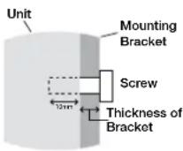
Screw length should equal depth of hole (10mm) + the thickness of mounting bracket.
screws longer than 10mm, check the depth of the hole. (Recommended Fasten Force: 470 - 635N·cm) NEC recommends mounting interfaces that comply with UL1678 standard in North America.
- Prior to mounting, inspect the installation location to insure that it is strong enough to support the weight of the unit so that the unit will be safe from harm.
- Refer to the instructions included with the mounting equipment for detailed information.
Mounting location
The ceiling and wall must be strong enough to support the monitor and mounting accessories.
- DO NOT install in locations where a door or gate can hit the unit.
DO NOT install in areas where the unit will be subjected to strong vibrations and dust.
DO NOT install near where the main power supply enters the building. - Do not install in where people can easily grab and hang onto the unit or the mounting apparatus.
- When mounting in a recessed area, as in a wall, leave at least 4 inches (10cm) of space between the monitor and the wall for proper ventilation.
- Allow adequate ventilation or provide air conditioning around the monitor, so that heat can properly dissipate away from the unit and mounting apparatus.
Mounting on Ceiling
- Ensure that the ceiling is sturdy enough to support the weight of the unit and the mounting apparatus over time, against earthquakes, unexpected vibrations, and other external forces.
- Be sure the unit is mounted to a solid structure within the ceiling, such as a support beam. Secure the monitor using bolts, spring lock washers, washer and nut.
- DO NOT mount to areas that have no supporting internal structure. DO NOT use wood screws or anchor screws for mounting. DO NOT mount the unit to trim or to hanging fixtures.
Maintenance
- Periodically check for loose screws, gaps, distortions, or other problems that may occur with the mounting apparatus. If a problem is detected, please refer to qualified personnel for service.
- Regularly check the mounting location for signs of damage or weakness that may occur over time.
Orientation
When using the display in the portrait position, the monitor should be rotated clockwise so that the left side is moved to the top and the LED indicator light is on the bottom. This will allow for proper ventilation and will extend the lifetime of the monitor. Improper ventilation may shorten the lifetime of the monitor.

Attaching Mounting Accessories
The display is designed for use with the VESA mounting system.
1) Attach Mounting Accessories
Mounting accessories can be attached while the monitor is on the Tabletop Stand in the upright position (Figure 1). Be careful to avoid tipping monitor when attaching accessories. After accessories are attached, stand can be removed (Figure 3).
Mounting accessories can be attached with the monitor in the face down position. To avoid damaging the screen face, place the protective sheet on the table underneath the LCD. The protective sheet was wrapped around the LCD in the original packaging. Make sure there is nothing on the table that can damage the monitor.
When using mounting accessories other than NEC compliant and approved, they must comply with the VESA-compatible mounting method. NEC strongly recommends using screws M6 size and 10mm in length. If using screws longer than 10mm, check the depth of the hole. (Recommended Fasten Force: 470-635N•cm) NEC recommends using mounting interface that comply with UL1678 standard in North America.
This device cannot be used or installed without the Tabletop Stand or other mounting accessory for support. For proper installation it is strongly recommended to use a trained, NEC authorized service person. Failure to follow NEC standard mounting procedures could result in damage to the equipment or injury to the user or installer. Product warranty does not cover damage caused by improper installation. Failure to follow these recommendations could result in voiding the warranty.
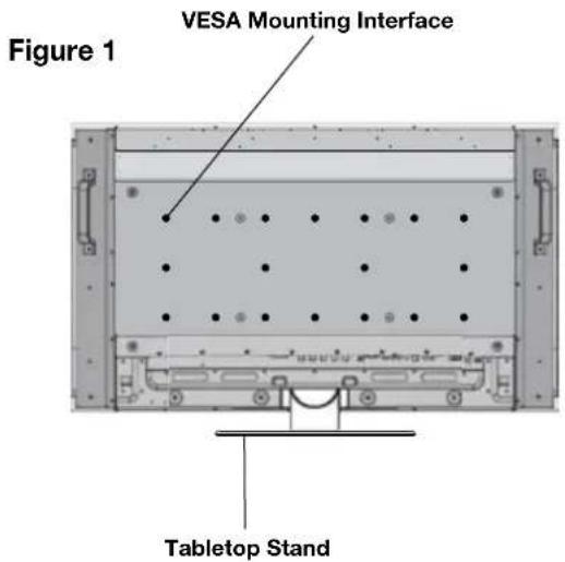

2) Stand Removal
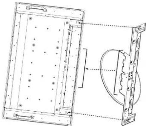
To detach stand, place the monitor face down as shown in Figure 2. Remove the screws from the back of the stand as indicated in Figure 3. Remove the 2 additional screws located on the bottom of the stand (Figure 3). Lift up stand to remove. After stand is removed, replace the screws into the original holes.
NOTE: The number of screws will vary depending on the model (Figure 3).
To reattach the stand. Place the monitor face down on the protective sheet to prevent damage. Remove the screws from their holes as indicated in Figure 3. Slide the stand into place, making sure that the inside tabs located on the left and right of the stand are placed into the corresponding slots on the display (Figure 4). The bottom of the stand should fit underneath the monitor. Use the screws to secure the stand to the monitor
NOTE: When removing stand, be sure to remove the 2 screws on the bottom of the stand (Figure 3). Not removing these screws will result in damage to the display.
Figure 3


Figure 4
natural_image
Technical line drawing of a mechanical assembly with mounting holes and a circular component (no text or symbols)3) Ventilation Requirements
When mounting in an enclosure or in a recessed area allow heat to disperse, leave space between surrounding the monitor and surrounding objects allow heat to disperse, as shown in Figure 5.
4) Main Power Switch Cover
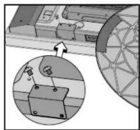
The Main Switch Cover will be attached in one of two ways, depending on the orientation of the monitor. When the Main Switch Cover is used when the stand is attached the longer side of the cover will go underneath. When used without the stand, the short side of the cover will go underneath (Figure 6).
5) Prevent Tipping
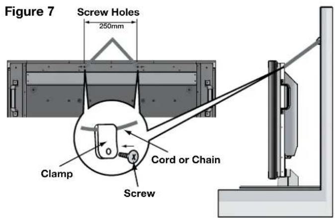
When using the display with the Tabletop Stand fasten the LCD to a wall using a cord or chain that can support the weight of the monitor (M40 approx. 32.6kg; M46 approx. 39.3kg) in order to prevent the monitor from falling. Fasten the cord or chain to the monitor using the provided clamp and screw (Figure 7). Before attaching the LCD monitor to the wall, make sure that the wall can support the weight of the monitor. Be sure to remove the cord or chain from the wall before moving the LCD.
Figure 5
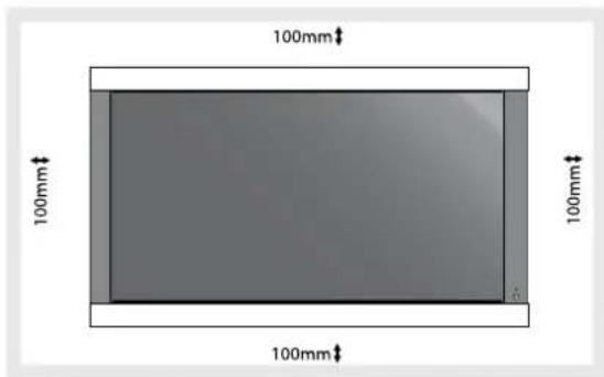
Figure 6
natural_image
Technical diagram showing a mechanical assembly with a magnified inset of a component (no visible text or symbols)Main switch cover (with stand) The longer side of the cover is toward the bottom of the display.

natural_image
Mechanical assembly diagram showing a bracket with mounting holes and a magnified inset of a component detail (no text or symbols)Main switch cover (without stand) The shorter side of the cover is toward the bottom of the display.
Part Names and Functions
Control Panel

Buttons and Main Power Switch are located underneath and behind the bezel.
1) POWER
Switches the power on/off. (See page 24)
2) MUTE
Switches the audio mute ON/OFF.
3) INPUT
Selects which signal connected to the display is shown. ([DVI], [VGA], [RGB/HV], [HDMI], [DVD/HD], [VIDEO], [TV])
Acts as SET button within the OSM menu.
4) PLUS (+)
Increases the setting adjustment within OSM menu. Increases the audio output level when the OSM is off.
5) MINUS (-)
Decreases the setting adjustment within OSM menu. Decreases the audio output level when the OSM is off.
6) UP (▲)
Activates the OSM menu when the OSM menu is off. Moves the highlighted area up to select which setting to be adjust within OSM menu.
7) DOWN (▼)
Activates the OSM menu when the OSM menu is off. Moves the highlighted area down to select which setting to be adjust within OSM menu.
8) EXIT
Activates the OSM menu when the OSM menu is off. Exits from the current menu being displayed to the previous menu within the OSM.
9) Remote control sensor and Power indicator
Receives the signal when using the wireless remote control. (See page 14) Glows green when the LCD monitor is in active. Glows red when the LCD is in POWER OFF (ECO standby) mode. Glows Amber when the LCD is in POWER OFF (standby). Amber blinks when the monitor is in Power Save Mode. Green and Amber blink alternately while in Power Standby with the “SCHEDULE SETTINGS” function enabled. When a component failure is detected within the monitor, the indicator will blink red.
10) Main Power Switch
Seesaw Switch for the main power on/off.
Control Key Lock Mode
This function completely locks out access to all Control Key functions. To enable the Control Key Lock Mode, press both “▲” and “▼” simultaneously and hold down for three (3) seconds. To go back to user mode, press both “▲” and “▼” simultaneously and hold down for three (3) seconds.

Denotes AV unit function. All AV functions are enabled with the AV unit is installed. Not all models have the AV unit installed.

Denotes Digital Tuner function. All DTV and AV functions are enabled when the DTV unit is installed. Not all models will have the digital tuner installed.
Terminal Panel
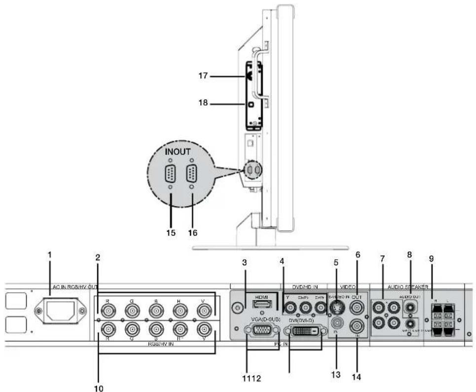
1) AC IN
Connects with the supplied power cord.
2) RGB/HV OUT [R, G, B, H, V] (BNC)
Outputs the signal from the RGB/HV IN connector to an input on a separate device.
3) HDMI connector
To input digital HDMI signals.
4) DVD/HD in
Connecting equipment such as a DVD player, HDTV device, or Laser disc player.
5) S-VIDEO in AV
Input S-video.
6) VIDEO out AV
Output the composite video signal from the VIDEO IN connection.
7) AUDIO IN AV
Input the audio signal from external equipment such as a computer, VCR or DVD player.
8) AUDIO OUT AV
Output the audio signal from the AUDIO IN 1, 2, 3, HDMI, and TV jack to an external device (stereo receiver, amplifier, etc.).
9) SPEAKER TERMINALS AV
Output the audio signal from AUDIO 1, 2, 3, HDMI, and TV to external speakers jack.
NOTE: Speaker Terminal is for 15W + 15W (8 ohm).
10) RGB/HV IN [R, G, B, H, V] (BNC)
Input RGB signals or signals from other RGB equipment. A Sync-on-Green signal can be connected to the G connector.
11) VGA (D-SUB15)
Analog computer input.
12) DVI-D AV
Input digital RGB signals from a computer or HDTV device having a digital RGB output.
13) VIDEO IN AV
Composite video input.
14) VIDEO IN AV
BNC video input.
15) EXTERNAL CONTROL (mini D-Sub 9 pin)
Connect RS232-C input to external equipment such as a PC in order to control RS232-C functions.
16) EXTERNAL CONTROL (mini D-Sub 9 pin)
Connect RS232-C output.
To connect to multiple Multeos monitors via daisy RS232-C Chain.
17) RF IN DTV
TV signal input.
Optical digital audio out.

Denotes AV unit function. All AV functions are enabled with the AV unit is installed. Not all models have the AV unit installed.

Denotes Digital Tuner function. All DTV and AV functions are enabled when the DTV unit is installed. Not all models will have the digital tuner installed.
Part Names and Functions - continued
Remote Control Functions

1) POWER
Switches the power on/off.
*If the Power Indicator on the display is not glowing, then no controls will work.

Denotes AV unit function. All AV functions are enabled with the AV unit is installed. Not all models have the AV unit installed.

Denotes Digital Tuner function. All DTV and AV functions are enabled when the DTV unit is installed. Not all models will have the digital tuner installed.
2) INPUT
Selects which input signal ([DVI], [VGA], [RGB/HV], [HDMI], [DVD/HD], [VIDEO], [TV], [OPTION]) to be displayed.
3) PICTURE MODE
Selects picture mode, [HIGHBRIGHT], [STANDARD], [sRGB], [CINEMA]. See page 25. HIGHBRIGHT: for moving images STANDARD: for images sRGB: for text based images CINEMA: for movies
4) SIZE
Selects aspect ratio of the displayed image. [FULL], [NORMAL], [WIDE], and [ZOOM].
5) KEYPAD
Set and change passwords. Set REMOTE ID. Select TV channel.
6) DISPLAY
Turn on/off the Information OSM. See page 25.
7) ▲ ▼
Move highlighted area up or down. Moves the PIP sub-picture.
8) AUTO SETUP
Enters AUTO SETUP menu.
9) CHANNEL RETURN DTV
Return to previous channel.
10) VOLUME AV
Increases/Decreases sound level.
11) STILL
ON/OFF: Activates/deactivates still picture mode. CAPTURE: Captures still picture.
12) PICTURE in PICTURE AV
ON/OFF: Turns PIP on or off. INPUT: Changes the input signal of PIP. CHANGE: Swaps inner picture with outer picture.
| Sub Picture | ||||||||
| DVI VGA | RGB/HV HDMI | DVD/HD | VIDEO TV | |||||
| MainPicture | DVI - - - | √ | √ | √ | ||||
| VGA - - - | √ | √ | √ | |||||
| RGB/HV - - - | √ | √ | √ | |||||
| HDMI - - - | √ | √ | √ | |||||
| DVD/HD | √ | √ | √ | √ | - | √ | √ | |
| VIDEO | √ | √ | √ | √ | √ | - | √ | |
| TV | √ | √ | √ | √ | √ | √ | - | |
13) REMOTE ID
Activates REMOTE ID function. See page 15.
14) GUIDE DTV
Enter on screen program guide.
15) AUDIO INPUT AV
Select the Audio source
NOTE: It is possible to play audio from a source that is different from the video source. When setting parental controls for video, be aware that this content is not filtered.
16) SOUND AV
Artificial surround sound.
17) ENTER DTV
Go to channel selected.
18) MENU
Turns ON/OFF menu mode.
19) SET
Makes selection.
20) - , +
Increases or decreases adjustment.
Moves the PIP sub-picture.
21) EXIT
Goes to previous menu.
22) Channel DTV
Go up or down channel selections.
23) MUTE AV
Mutes audio output
24)

Activates closed captioning.
25) SLEEP
Sleep timer.
26) MTS DTV
Multi-track sound.
Changing the channel DTV
Both Analog and Digital channels are available using this tuner. In addition to the CH+ and CH- buttons channels can be changed in the following method.
Tuning Analog Channels
Input the desired channel number using the keypad, then press [SET] or [ENT] to immediately tune to the new channel. If the number is input and [SET] or [ENT] is not pushed, after a few seconds the channel will be changed. For example to tune to channel 5, press [5] then press [SET] or [ENT].
Tuning Digital Channels
To tune in to a digital sub-channel enter the number of the main channel, then a dash followed by the number of the sub-channel. For example to tune to digital channel 5-1, press [5] then [-] then [1]. Press [SET] or [ENT] to tune.

Denotes AV unit function. All AV functions are enabled with the AV unit is installed. Not all models have the AV unit installed.

Denotes Digital Tuner function. All DTV and AV functions are enabled when the DTV unit is installed. Not all models will have the digital tuner installed.
Part Names and Functions - continued
Remote Control Operating Range
Operating Range for the Remote Control
Point the top of the remote control toward the monitor's remote sensor while pressing buttons. The remote control can be used from the front of the monitor at a maximum distance of 7 m/23 ft. from the front of the LCD monitor's remote control sensor. The maximum horizontal and vertical angle for use of the remote is 30 degrees within a distance of 3.5 m/10 ft.

CAUTION
The remote control system may not function when direct sunlight or strong illumination strikes the remote control sensor of the LCD monitor, or when there is an object in the path of the sensor.
Handling the Remote Control
Do not open the remote control other than to install batteries.
Do not allow water or other liquid to splash onto the remote control. If the remote control gets wet, wipe it dry immediately.
Avoid exposure to heat and steam.
Remote Control ID Function
REMOTE CONTROL ID
The remote control included with the display can be used to control up to 26 individual Multeos monitors using what is called the REMOTE CONTROL ID mode. The REMOTE CONTROL ID mode works in conjunction with the Monitor ID, allowing control of up to 26 individual Multeos monitors. For example: if there are many monitors being used in the same area, a remote control in normal mode would send signals to every monitor at the same time Figure 1. Using the remote in REMOTE CONTROL ID mode will only operate one specific monitor within the group Figure 2.
TO SET REMOTE CONTROL ID:
While holding down the REMOTE ID SET button on the remote control, use the KEYPAD to input the Monitor ID (1-26) of the display to be controlled via remote. The remote can then be used to operate the monitor having that specific Monitor ID number.
When 0 is selected or when the remote control is in normal mode, all monitors will be operated.
TO USE REMOTE CONTROL ID MODE
ID Mode - To enter ID Mode press the REMOTE ID SET button and hold down for 2 seconds.
Normal Mode - To return to Normal Mode press the REMOTE ID RESET button and hold down for 2 seconds.
In order for this feature to work properly, the display must be assigned a Monitor ID number. The Monitor ID number can be assigned under the MULTI DISPLAY menu in the OSM (See page 30).

flowchart
graph TD
    A["Monitor ID:1 Monitor ID:2 Monitor ID:3"] --> B["Remote works Remote works Remote works"]
    C["Monitor ID:1 Monitor ID:2 Monitor ID:3"] --> D["Remote works Remote works Remote works"]
    E["Remote works Remote works Remote works"] --> F["Figure 1 Remote in Normal mode or the REMOTE ID is set to 0"]
    G["Remote works Remote works Remote works"] --> H["Figure 2 Remote set up to use Remote ID:3"]
INFORMATION OSM
ID number assigned to display
Press the “DISPLAY” button on the remote to bring up the Information OSM. The Information OSM shows the monitor ID number and other information such as signal type, zoom method, etc.
Please see installation on page 6 of this manual and follow all installation instructions.
1) Determine the installation location.
CAUTION: Installing your LCD display must be done by a qualified technician. Contact your dealer for more information.
CAUTION: MOVING OR INSTALLING THE LCD MONITOR MUST BE DONE BY TWO OR MORE PEOPLE. Failure to follow this caution may result in injury if the LCD monitor falls.
CAUTION: Do not mount or operate the display upside down, face up, or face down.
CAUTION: This LCD has a temperature sensor and cooling fan. If the LCD becomes too hot, the cooling fan will turn on automatically. If the LCD becomes overheated while the cooling fan is running, the "Caution" menu will appear. If the "Caution" menu appears, discontinue use and allow the unit to cool. Using the cooling fan will reduce the likelihood of early circuit failure and may help reduce image degradation and "image persistence". If the LCD is used in an enclosed area or if the LCD panel is covered with a protective screen, please check the inside temperature of the monitor by using the "HEAT STATUS" control in the OSM (see page 30). If the temperature is higher than the normal operating temperature, please turn the cooling fan to ON within the FAN CONTROL menu within the OSM(see page 30).
IMPORTANT
Lay the protective sheet, which was wrapped around the LCD monitor when it was packaged, beneath the LCD monitor so as not to scratch the panel.
2) Install the remote control batteries.
The remote control is powered by two 1.5V AA batteries. To install or replace batteries:

natural_image
Three technical diagrams showing a vehicle's rear and side views with arrows indicating motion or force (no text or symbols present)A. Press and slide to open the cover.
B. Align the batteries according to the (+) and (−) indications inside the case.
C. Replace the cover.
CAUTION: Incorrect usage of batteries can result in leaks or bursting. NEC recommends the following battery use:
- Place “AA” size batteries matching the (+) and (-) signs on each battery to the (+) and (-) signs of the battery compartment.
- Do not mix battery brands.
- Do not combine new and old batteries. This can shorten battery life or cause liquid leakage of batteries.
- Remove dead batteries immediately to prevent battery acid from leaking into the battery compartment.
- Do not touch exposed battery acid, it may injure skin.
NOTE: If you do not intend to use the Remote Control for a long period of time, remove the batteries.
3) Connect external equipment.
- To protect the external equipment, turn off the main power before making connections.
• Refer to your equipment user manual for further information.
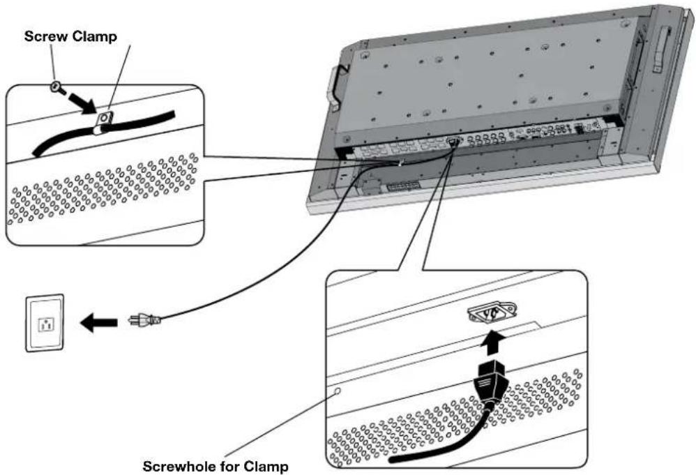
4) Connect the supplied power cord.
- The equipment should be installed close to an easily accessible power outlet.
- Please attach power cord to the LCD monitor by attaching the screw and clamp.
- Fully insert the prongs into the power outlet socket. A loose connection may cause image degradation.
NOTE: If you use this monitor at AC 220 - 240V, please refer to "Safety Precautions and Maintenance & Recommended Use" sections of this manual for proper selection of AC power cord.
5) Switch on the power of all the attached external equipment.
When connected with a computer, switch on the power of the computer first.
6) Operate the attached external equipment.
Display the signal from the desired input source.
7) Adjust the sound AV
Make volume adjustments as required.
8) Adjust the screen (See page 27).
Make adjustments of the screen display position when necessary.
9) Adjust the image (See page 27).
Make adjustments such as brightness or contrast when required.
10) Recommended Adjustments
To reduce the risk of the "image persistence", please adjust the following items based on the application being used:
"DATE & TIME" and "SCHEDULE SETTINGS" (See pages 28 and 29) "SCREEN SAVER", and "SIDE BORDER COLOR" (See page 30)
It is recommended that the "FAN CONTROL" setting (see page 30) be turned to ON also.
AV Denotes AV unit function. All AV functions are enabled with the AV unit is installed. Not all models have the AV unit installed.
DTV Denotes Digital Tuner function. All DTV and AV functions are enabled when the DTV unit is installed. Not all models will have the digital tuner installed.
Connections
Before connecting external equipment to LCD:
First turn off the power to all of the equipment associated with the LCD as well as that of the equipment to be connected.
For questions regarding external equipment please refer to the user's manual supplied with that equipment.
Connecting the LCD Monitor to a PC
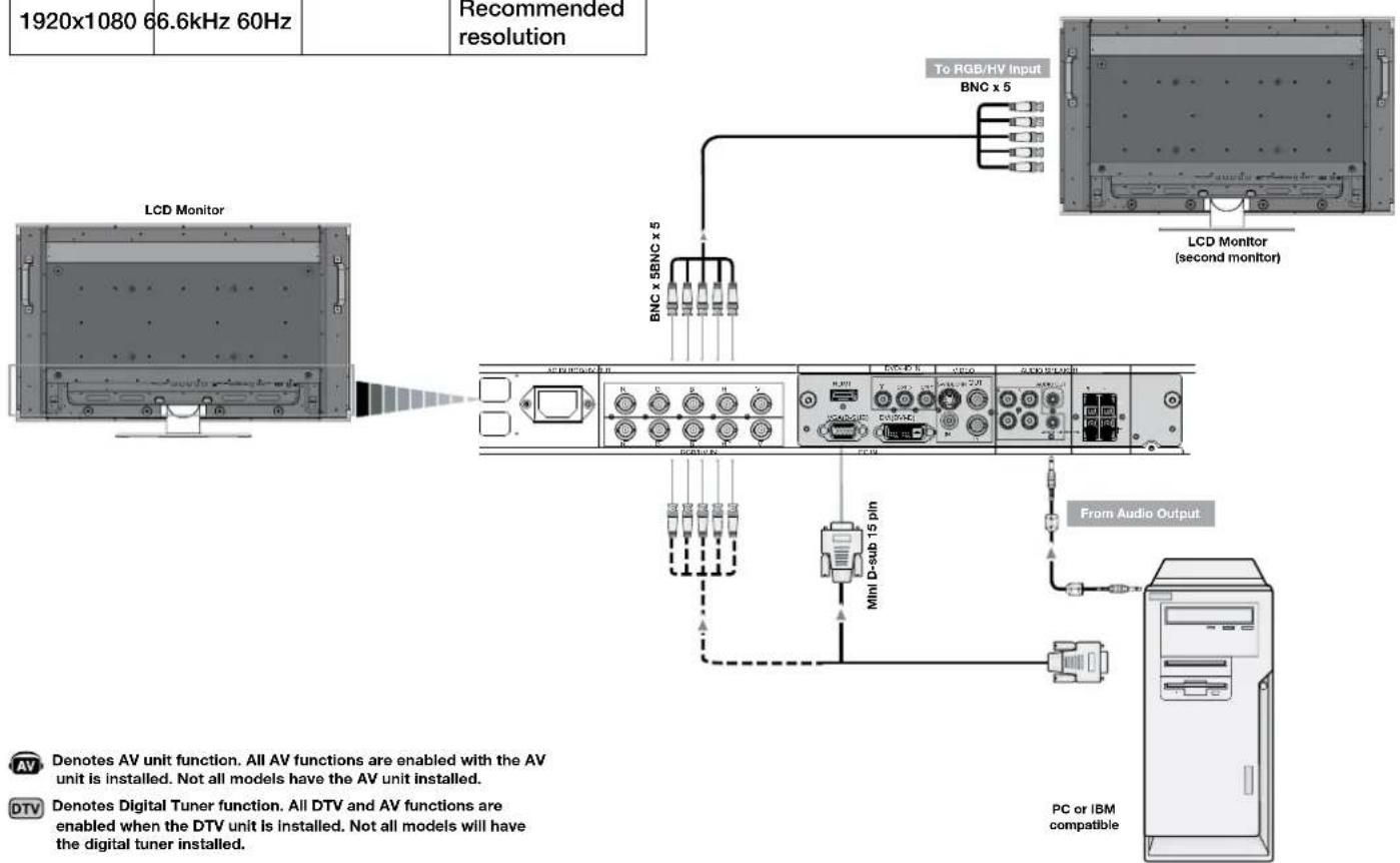
Connecting your computer to your LCD monitor will enable you to display your computer's screen image.
Some video cards having a pixel clock over 165MHz may not display images correctly.
The LCD monitor will automatically adjust to a preset timing to display the proper image.
| Resolution | Scanning frequency | RemarksHorizontal Vertical | |
| 640x480 31.5kHz 60Hz | |||
| 800x600 37.9kHz 60Hz | |||
| 1024x768 48.4kHz 60Hz | |||
| 1280x768 48.0kHz 60Hz | |||
| 1360x768 48.0kHz 60Hz | |||
| 1280x1024 64.0kHz 60Hz | |||
| 1600x1200 75.0kHz 60Hz | Compressed image | ||
| 1920x1080 66.6kHz 60Hz | Recommended resolution | ||
To connect to the VGA connector (mini D-sub 15 pin) on the LCD monitor, use the provided RGB signal cable (mini D-sub 15 pin to mini D-sub 15 pin).
To connect to the RGB/HV connector (BNC) on the LCD monitor, use a mini D-sub 15 pin to BNC x 5 signal cable (not included). Select RGB/HV from the INPUT button.
When connecting to a second LCD monitor, use the RGB/HV OUT connector (BNC).
The AUDIO IN1, 2, 3 can be used to choose the audio source. To select, use the AUDIO INPUT button.
English-18
Connecting to a Macintosh ^® Computer
Connecting your Macintosh computer to your LCD monitor will enable you to display your computer's screen image. Some video cards or drivers may not display images correctly.
To connect to the VGA connector (mini D-sub 15 pin) on the LCD monitor, use the RGB signal cable (mini D-sub 15 pin to mini D-sub 15 pin) included with the display.
NOTE: For older Macintosh computers, use Macintosh cable adapter to connect to your Macintosh's video port. To obtain the Macintosh cable adapter call NEC Display Solutions of America, Inc. at (800) 632-4662
To connect to the RGB/ HVconnector (BNC) on the LCD monitor, use a mini D-sub 15 pin to BNC x 5 signal cable (not included).
If you will be connecting the LCD monitor to a Macintosh PowerBook, set "Mirroring" to off.
Refer to your Macintosh's owner's manual for more information about your computer's video output requirements and any special identification or configuring that may be required.
The AUDIO IN1, 2, 3 can be used to choose the audio source. To select, use the AUDIO INPUT button.

AV Denotes AV unit function. All AV functions are enabled with the AV unit is installed. Not all models have the AV unit installed.
DTV Denotes Digital Tuner function. All DTV and AV functions are enabled when the DTV unit is installed. Not all models will have the digital tuner installed.
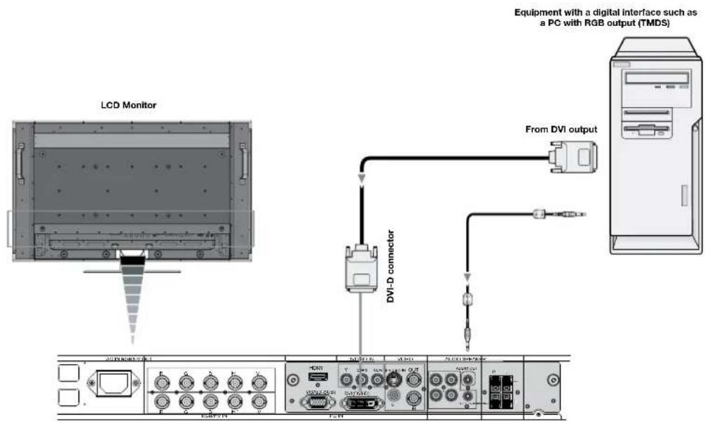
Connecting to a Computer with Digital Output
Connections can be made with devices equipped with a digital interface that complies with the DVI (Digital Visual Interface) standard.
• DVI connector also accepts a DVI-D cable.
- Input TMDS signals conforming to DVI standards.
- To maintain display quality, use a cable recommended by DVI standards.
The AUDIO IN1, 2, 3 can be used to choose the audio source. To select, use the AUDIO INPUT button.

Denotes AV unit function. All AV functions are enabled with the AV unit is installed. Not all models have the AV unit installed.

Denotes Digital Tuner function. All DTV and AV functions are enabled when the DTV unit is installed. Not all models will have the digital tuner installed.
Connecting a DVD Player with component out AV
Connecting your DVD player to your LCD monitor will enable you to display DVD video.
Refer to your DVD player user's manual for more information.
Connect the LCD Monitor to a DVD Player
- To connect the DVD/HD IN connector (RCA) on the LCD monitor, use a separately available RCA connector cable.
- Some DVD players may have different connectors such as a DVI-D connector.
- Select [DVI/HD] mode from the "DVI MODE" menu when you connect a DVI-D connector. For DVI Mode selection, see "DVI MODE" on page 31.
- The AUDIO IN1, 2, and 3 (both RCA) can be used for audio input. For connection, select [IN1, IN2] or [IN3] from the AUDIO INPUT button.

flowchart
graph TD
    A["Left Audio"] --> B["From DVD Component Video Output"]
    C["Right Audio"] --> B
    D["RCA"] --> B
    E["DVI-D Connector"] --> B
    F["LCD Monitor"] --> G["Output Panel"]
    style A fill:#f9f,stroke:#333
    style C fill:#f9f,stroke:#333
    style D fill:#f9f,stroke:#333
    style E fill:#ccf,stroke:#333
    style F fill:#ccf,stroke:#333
    style G fill:#dfd,stroke:#333

Denotes AV unit function. All AV functions are enabled with the AV unit is installed. Not all models have the AV unit installed.

Denotes Digital Tuner function. All DTV and AV functions are enabled when the DTV unit is installed. Not all models will have the digital tuner installed.
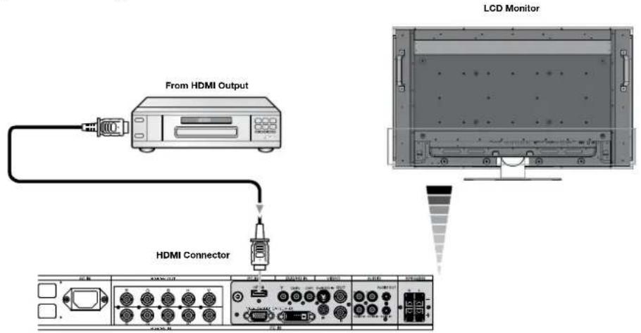
Connecting a DVD Player with HDMI out
Connecting your DVD player to your LCD monitor will enable you to display DVD video.
Refer to your DVD player user's manual for more information.
Connect the LCD Monitor to a DVD Player
- Please use an HDMI cable that has the HDMI logo.
- It may take a few seconds to show the signal.
• We do not support PC-DVI signals.
Connecting a DVD Player with SCART out AV
Connecting your DVD player to your LCD monitor will enable you to display SCART.
Connect the LCD Monitor to a DVD Player AV
- To connect the DVD/HD IN connector (RCA) on the LCD monitor and connect the video (sync) and the Video In connector (RCA), use a separately available RCA connector cable.
- Some DVD players may have different connectors such as DVI-D connector.
- Select [ON] mode from the "SCART MODE" menu when you use a SCART connector. Mode selection, see "SCART" on page 31.
- The AUDIO IN 2 and 3 (both RCA) can be used for audio input. For connection, select [IN1] or [IN3] from the AUDIO INPUT button.


Denotes AV unit function. All AV functions are enabled with the AV unit is installed. Not all models have the AV unit installed.

Denotes Digital Tuner function. All DTV and AV functions are enabled when the DTV unit is installed. Not all models will have the digital tuner installed.
Connecting to a Stereo Amplifier AV
You can connect your stereo amplifier to your LCD monitor. Refer to your amplifier owner's manual for more information.
Connect the LCD Monitor to a Stereo Amplifier AV
- Turn on the LCD monitor and the amplifier only after all connections have been made.
- Use an RCA cable to connect the AUDIO OUT connector (RCA) on the LCD monitor and the audio input on the amplifier.
- Do not reverse the audio left and right jacks.
• The AUDIO IN is used for audio input.
• The AUDIO OUT jack outputs sound from the selected Audio input.

flowchart
graph TD
    A["VCR or Laser disc player"] -->|To Audio Right| B["LCD Monitor"]
    A -->|To Audio Left| B
    B --> C["RCA"]
    C --> D["Amplifier"]
    D --> E["External Speakers"]
    D --> F["To Audio Right"]
    D --> G["To Audio Left"]

Denotes AV unit function. All AV functions are enabled with the AV unit is installed. Not all models have the AV unit installed.

Denotes Digital Tuner function. All DTV and AV functions are enabled when the DTV unit is installed. Not all models will have the digital tuner installed.
Basic Operation - Power ON and OFF Modes
The LCD monitor power indicator will turn green while powered on and will turn red while powered off.
NOTE: The Main Power Switch must be in the ON position in order to power up the monitor using the remote control or the Power Button on the front of the LCD.

Power Indicator
| Mode Status Indicator Light | |
| Power ON Green | |
| Power OFF (ECO STANDBY)*Power consumption under 1W | Red |
| Power OFF (STANDBY)Power consumption under 5W | Amber |
| Power Save Amber Blinking | |
| Power Standby when“SCHEDULE SETTINGS”enabled | Green and Amberblink alternately |
| Diagnosis (Detecting failure) Red | Blinking(See Trouble Shooting page 41) |
| *When in Eco Standby Mode RS-232C controls do not function. | |
Power Management
The LCD monitor follows the VESA approved DPM Power Management function.
The power management function is an energy saving function that automatically reduces the power consumption of the display when the keyboard or the mouse has not been used for a fixed period of time.
The power management feature on your new display has been set to the “ON” mode. This allows your display to enter a Power Saving Mode when no signal is detected. This could potentially increase the lifetime of the display while power consumption is decreased.
STANDBY mode is used when the display is connected to an RS-232C cable or when using the INPUT DETECT function.
ECO STANDBY uses less power, but the RS-232C and INPUT DETECT functions are not available.
Picture Size
The size of the picture can be changed depending on the aspect ratio (4:3, 16:9, etc.) of the input signal.
DVI, VGA, RGBH/V, OPTION FULL →ZOOM →NORMAL

HDMI, DVD/HD, VIDEO, TV FULL→WIDE→ZOOM→NORMAL
| Signal Type | NORMAL SIZE RECOMMENDED SIZE |
| 4:3 | |
| ZOOM (DYNAMIC) | |
| Squeeze | |
| Letterbox |
Picture Mode
Choose the Picture Mode that is most suitable for the type of content that is shown.
Standard: for images
sRGB: For text based applications.
Highbright: for moving images
Cinema: for movies
| DVI, VGA, RGB/HV, OPTION | STANDARD → sRGB → HIGHBRIGHT |
| HDMI, DVD/HD, VIDEO, TV | STANDARD → CINEMA → HIGHBRIGHT AV |
Information OSM
The Information OSM provides information such as: Monitor ID, Input Source, Picture Size, etc. Press the DISPLAY button on the remote to bring up the Information OSM. See page 35 for detailed explanation.

OSM (On-Screen Manager) Controls


flowchart
graph TD
    A["Remote Control"] --> B["Press UP or DOWN button to select sub-menu."]
    B --> C["Press SET."]
    C --> D["Press UP, DOWN, PLUS, or MINUS to select the function or setting to be adjusted."]
    D --> E["Press MENU or EXIT."]
    F["Control Panel"] --> G["Press UP or DOWN button to select."]
    G --> H["Press INPUT button to decide."]
    H --> I["Press UP, DOWN, PLUS, or MINUS to select."]
    I --> J["Press EXIT."]
    K["OSM Screen"] --> L["DVI"]
    L --> M["Select O: Go to Adjustment U: Return U: Close"]
English-26
OSM Setting
| PICTURE BRIGH | TNESS Adjusts the overall image and background brightness. Press + or - to adjust. | |
| CONTRAST Adjusts the image brightness in relationship to the background. Press + or - to adjust. Note: The sRGB picture mode is standard and cannot be changed. | ||
| SHARPNESS Adjusts the crispness of the image. Press + or - to adjust. | ||
| BLACK LEVEL Adjusts the image brightness in relationship to the background. Press + or - to adjust. | ||
| TINT HDMI, DVD/HD, VIDEO, TV input only | Adjusts the tint of the screen. Press + or - to adjust. | |
| COLOR HDMI, DVD/HD, VIDEO, TV input only | Adjusts the color depth of the screen. Press + or - to adjust. | |
| COLOR TEMPERATURE Adjusts the color temperature of the entire screen. A low color temperature will make the screen reddish. A high color temperature will make the screen bluish. Note: The sRGB picture mode is set to a predefined 6500 K standard and cannot be changed. | ||
| COLOR CONTROL DVI, VGA, RGB/HV, HDMI input only | Adjusts the levels of the Red, Yellow, Green, Cyan, Blue, Magenta and Saturation. Note: The sRGB picture mode is standard and cannot be changed. | |
| GAMMA SELECTION Select a display gamma for best picture quality. | ||
| NATIVE | Gamma correction is handled by the LCD panel. | |
| 2.2 | Typical display gamma for use with a PC. | |
| 2.4 | Good for video (TV, DVD, etc.). | |
| S GAMMA | Special gamma for certain types of movies. Raises the dark parts and lowers the light parts of the image. (S-Curve) | |
| DICOM SIM. | DICOM GSDF curve simulated for LCD type. | |
| PROGRAMMABLE | A programmable gamma curve can be loaded using NEC software. | |
| ADAPTIVE CONTRAST HDMI, DVD/HD, VIDEO, TV input only | Sets the level of adjustment for dynamic contrast. | |
| OFF | ||
| MID | ||
| HIGH | ||
| MOVIE SETTINGS HDMI, DVD/HD, VIDEO, TV input only | ||
| NOISE REDUCTION | Adjusts the amount of noise reduction. Press + or - to adjust. Selects Film mode. | |
| FILM MODE | ||
| PICTURE RESET Resets the following settings within the PICTURE menu back to factory setting: BRIGHTNESS, CONTRAST, SHARPNESS, BLACK LEVEL, TINT, COLOR TEMPERATURE, COLOR CONTROL, GAMMA SELECTION, ADAPTIVE CONTRAST, MOVIE SETTINGS. | ||
| ADJUST AUTO | SETUP VGA and RGB/HV input only | Automatically adjusts screen size, H position, V position, Clock, Clock Phase, White Level, and Black Level. |
| AUTO ADJUST VGA and RGB/HV input only | H Position, V Position and Clock Phase are adjusted automatically upon power on. | |
| H POSITION Controls the horizontal position of the image within the Display area of the LCD. Press + to move right. Press - to move left. | ||
| V POSITION Controls the vertical position of the image within the Display area of the LCD. Press + to move up. Press - to move down. | ||
| CLOCK VGA and RGB/HV input only | Press + to expand the width of the image on the right of the screen. Press - to narrow the width of the image on the left. | |
| CLOCK PHASE VGA, RGB/HV, DVD/HD input only | Adjusts the visual “noise” on the image. | ||
| H RESOLUTION DVI, VGA, RGB/HV input only | Adjusts the horizontal size of the image. | ||
| V RESOLUTION DVI, VGA, RGB/HV input only | Adjusts the vertical size of the image. | ||
| ZOOM MODE Select the aspect ratio of the screen image. | |||
| BASE ZOOM | Choose the zoom methodSame aspect ratio as the LCD panel.14:9Expands a 4:3 picture to fill the screen in a non-linear (non-proportionate) manner and some of the image will be lost due to expansion. DYNAMIC is the same as FULL size image when HDTV 1080i signal is input. | ||
| 16:9 | |||
| 14:9 | |||
| DYNAMIC | |||
| OFF | Selecting “OFF” will display the image in a 1 by 1 pixel format. (If the input resolution is higher than a 1920 x 1080 resolution, the image will be scaled down to fit the screen. | ||
| CUSTOM | Displays an image as large as possible without changing the aspect ratio or cutting off part of the image. | ||
| ZOOM | Maintains the aspect ratio while zooming. | ||
| H ZOOM | Amount of horizontal zoom. Can be adjusted for each BASE ZOOM setting. | ||
| V ZOOM | Amount of vertical zoom. Can be adjusted for each BASE ZOOM setting. | ||
| H POS | Horizontal position. Can be adjusted for each BASE ZOOM setting. | ||
| V POS | Vertical position. Can be adjusted for each BASE ZOOM setting. | ||
| INPUT RESOLUTION VGA and RGB/HV input only | If there is a problem with signal detection, this function forces the monitor to display the signal at the desired resolution.If no problem is detected, the only available option will be “AUTO”. | ||
| AUTO | |||
| 1024x768 | |||
| 1280x768 | |||
| 1360x768 | |||
| 1366x768 | |||
| 1440x1050 | |||
| 1680x1050 | |||
| ADJUST RESET Resets the following settings within the ADJUST menu back to factory setting:AUTO ADJUST, H POSITION, V POSITION, CLOCK, CLOCK PHASE, H RESOLUTION, V RESOLUTION, ZOOM MODE, INPUT RESOLUTION. | |||
| BALANCE | |||
| TREBLE | |||
| BASS | |||
| PIP AUDIO Selects source of PIP audio. | |||
| AUDIO RESET Resets “AUDIO” options back to factory settings. | |||
| TIMER Sets the monitor to power off after a length of time between 1 and 24 hours. | |||
| SCHEDULE SETTING Creates a working schedule for the monitor to use. See page 34 for instructions. | |||
| SCHEDULE LIST List of schedules. | |||
| DATE & TIME Sets the date, time, and daylight saving region. Date & time must be set in order for the “SCHEDULE” function to operate. | |||
| YEAR | ||
| MONTH | ||
| DAY | ||
| TIME | ||
| DAYLIGHT SAVING | ||
| SCHEDULE RESET Resets the following settings within the SCHEDULE menu back to factory setting: OFF TIMER, SCHEDULE SETTINGS. | ||
| PIP | KEEP PIP MODE | Allows the monitor to remain in “PIP” mode after powering off. When Power is returned, PIP appears without having to enter the OSM. |
| PIP MODE Picture-in-Picture | ||
| OFF | ||
| PIP | ||
| POP | ||
| SIDE BY SIDE (ASPECT) | ||
| SIDE BY SIDE (FULL) | ||
| PIP SIZE Selects the size of the sub-picture used in Picture-in-Picture (PIP) mode. | ||
| SMALL | ||
| MIDDLE | ||
| LARGE | ||
| PIP POSITION Determines where the PIP appears on the screen. | ||
| PIP RESET Resets the following settings within the PIP menu back to factory setting: KEEP PIP MODE, PIP MODE, PIP SIZE, PIP POSITION. | ||
| OSM LANGUAGE Select the language used by the OSM. | ||
| ENGLISH | ||
| DEUTSCH | ||
| FRANÇAIS | ||
| ITALIANO | ||
| ESPAÑOL | ||
| SVENSKA | ||
| 日本語 | ||
| OSM TURN OFF Turns off the OSM after a period of inactivity. The preset choices are 10-240 seconds. | ||
| OSM POSITION Determines the location where the OSM appears on the screen. | ||
| UP | ||
| DOWN | ||
| LEFT | ||
| RIGHT | ||
| INFORMATION OSM Selects whether the information OSM is displayed or not. The information OSM will be displayed when the input signal or source changes. The information OSM will also give a warning when there is no-signal or the signal is out-of range.An interval between 3 to 10 seconds for the Information OSM to appear is available. | ||
| MONITOR INFORMATION Monitor Information. | ||
| OSM TRANSPARENCY Set | the transparency level of the OSM. | ||
| OFF | |||
| TYPE1 | |||
| TYPE2 | |||
| OSM RESET Resets the following settings within the OSM menu back to factory setting: OSM TURN OFF, OSM POSITION, INFORMATION OSM, and OSM TRANSPARENCY. | |||
| MULTI DISPLAY MONITOR ID Sets the monitor ID number from 1-26. | |||
| IR CONTROL Selects the mode of the monitor for use with the infra-red remote control when using the RS-232C daisy chain. | |||
| NORMAL | The monitor will be controlled normally by wireless remote controller. Choose “PRIMARY” for the first monitor within an RS232-C daisy chain. Choose “SECONDARY” for all subsequent monitors within an RS232-C daisy chain. Prevents the monitor from being controlled by wireless remote controller. To return to normal operation, press the “DISPLAY” button on the remote controller for 5 seconds. | ||
| PRIMARY | |||
| SECONDARY | |||
| LOCK | |||
| TILE MATRIX Allows one image to be expanded and displayed over multiple screens (up to 25) through a distribution amplifier. | |||
| H MONITORS | Number of monitors arranged horizontally. | ||
| V MONITORS | Number of monitors arranged vertically. | ||
| POSITION | Select which section of the tiled image to be displayed on the monitor. | ||
| TILE COMP | Turns the TILE COMP feature on. | ||
| ENABLE | Enables Tile Matrix. | ||
| POWER ON DELAY Adjusts the delay time between being in “standby” mode and entering “power on” mode. “POWER ON DELAY” can be set between 0 and 50 seconds. | |||
| MULTI DISPLAY RESET Resets the following settings within the MULTI DISPLAY menu back to factory setting: MONITOR ID, IR CONTROL, TILE MATRIX, POWER ON DELAY. | |||
| DISPLAY PROTECTION | POWER SAVE Sets how long the monitor waits to go into power save mode after a lost signal. | ||
| STANDBY MODE Lowers power consumption. Note: RS232-C Function is lost when in Eco Standby mode. | |||
| HEAT STATUS Displays status of the COOLING FAN, BRIGHTNESS and TEMPERATURE. | |||
| FAN CONTROL Cooling fan reduces the temperature of the display. | |||
| SCREEN SAVER Use the SCREEN SAVER function to reduce the risk of Image Persistence. | |||
| GAMMA | The gamma curve becomes narrow, reducing contrast and cutting down the risk of image retention. | ||
| BRIGHTNESS | The brightness is decreased when “ON” is selected. | ||
| MOTION | The screen image is slightly expanded and moves in 4 directions (UP, DOWN, RIGHT, LEFT) at user determined intervals. | ||
| SIDE BORDER COLOR | Adjusts the color of the side borders when a 4:3 image is displayed. Press + button, the bar will become lighter. Press - button, the bar will become darker. | ||
| AUTO BRIGHTNESS DVI, VGA, RGB/HV input only | Adjusts the brightness level according to the input signal. | ||
| CHANGE SECURITY PASSWORD | Allows the security password to be changed. Factory preset password is 0000. | ||
| SECURITY LOCK | Locks the security password. | ||
| DISPLAY PROTECTION RESET | Resets the following settings within the Picture menu back to factory setting: POWER SAVE, STANDBY MODE, FAN CONTROL, SCREEN SAVER, SIDE BORDER COLOR, AUTO BRIGHTNESS. | ||
| ADVANCED OPTION | INPUT DETECTAll inputs except for TV | Selects the method of input detection the monitor uses when more than two input devices are connected.The Monitor will not search the other video input ports.When the current video input signal is not present, then the monitor searches for a video signal from the other video input port. If the video signal is present in the other port, then the monitor switches the video source input port to the new found video source automatically. The monitor will not look for other video signals while the current video source is present.When the monitor is displaying a signal from the current source and a new secondary source is supplied to the monitor, the monitor will automatically switch to the new video source. When current video input signal is not present, the monitor searches for a video signal from the other video input port. If the video signal is present in the other port, then the monitor switches the video source input port to the new found video source automatically.DVD/HD or VIDEO inputs will have priority over DVI, VGA, and RGB/HV. When DVD/HD or VIDEO input signal is present the monitor will change and keep to the DVD/HD or VIDEO input. | |
| NONE | |||
| FIRST DETECTDVI, VGA, RGB/HVinput only | |||
| LAST DETECTDVI, VGA, RGB/HVinput only | |||
| VIDEO DETECT AV | |||
| LONG CABLE ON/OFFVGA and RGB/HV input only | Compensates for image degradation caused from using a long cable.Manually compensates for image degradation caused from using a long cable. | ||
| LONG CABLE MANUALVGA and RGB/HV input only | |||
| RED DELAY | Adjusts the phase of the red signal. | ||
| GREEN DELAY | Adjusts the phase of the green signal. | ||
| BLUE DELAY | Adjusts the phase of the blue signal. | ||
| RED SHARPNESS | Adjusts the performance degradation of the RED signal. | ||
| GREEN SHARPNESS | Adjusts the performance degradation of the GREEN signal. | ||
| BLUE SHARPNESS | Adjusts the performance degradation of the BLUE signal. | ||
| SOG PEAK. | Adjusts the shape of Sync on Green signal. | ||
| VIDEO EQ. | Optimize the shape (Tailing) of RED, GREEN and BLUE signals.Selects the terminate resistance for matching the cable impedance. | ||
| SYNC TERMINATE | |||
| DVI MODE Choose the DVI mode based on the input device connected via DVI connector. | |||
| DVI-PC | When a PC or similar equipment is connected.When a DVD player is connected. | ||
| DVI-HD | |||
| SCAN CONVERSION Selects the IP (Interlace to Progressive) conversion function. | |||
| PROGRESSIVE | Converts interlaced signals to progressive.This is the default setting.Disables IP conversion. This setting is best suited for motion pictures, but increases the risk of image retention. | ||
| INTERLACE | |||
| SCART MODE AV | Input mode for devices using SCART connectors.Selects the S-Video input port function. | ||
| S-VIDEO MODE AV | |||
| PRIORITY | When an S-Video cable is connected to the S-Video input, it will have priority over the composite input port. | ||
| SEPARATE | The S-Video port and Composite port can be selected as independent input ports. | ||
| COLOR SYSTEM AVVIDEO input only | The selected Color System depends on the video format of the input signal.Automatically chooses Color System setting based on input signal. | ||
| AUTO | |||
| NTSC | |||
| PAL | |||
| SECAM | |||
| 4.43NTSC | |||
| PAL-60 | |||
| SCAN MODE AVHDMI, DVD/HD, VIDEO, TV input only | Some video formats may require scan conversion in order to best display the image. | ||
| OVER SCAN | Image size is larger than what can be displayed. The image edge will appear cropped. Approximately 95% of the image will be shown on the screen | ||
| UNDER SCAN | Image size stays within the display area. The whole image is displayed on the screen. | ||
| ADVANCED OPTION RESET | Resets the following settings within the ADVANCED OPTION menu back to factory setting: INPUT DETECT, LONG CABLE ON/OFF, LONG CABLE MANUAL, DVI MODE, SCAN CONVERSION, S-VIDEO MODE, SCAN MODE. | ||
| FACTORY RESET Resets OSM options back to factory settings EXCEPT FOR: CHANGE SECURITY PASS-WORD and SECURITY PASSWORD. | |||
| TV TUNERDTVNot all models have the Digital Tuner installed. | TUNER | Choose AIR or Cable as TV source.Shows the status of the Digital TV signal.Searches for TV channels and stores them in memory.Searches for TV channels and stores them in memory without erasing previously stored channels.Performs fine adjustments to analog channels.Add or remove channels stored in memory.Add a label to the channel. | |
| TUNING BAND | |||
| CHECK DTV SIGNAL | |||
| CHANNEL SEARCH | |||
| ADD ON CHANNEL SEARCH | |||
| FINE TUNING | |||
| CHANNEL EDIT | |||
| CHANNEL LABELS | |||
| CONFIGURATION | |||
| MENU LANGUAGE | Set the Parental Control Password. Factory default password is 0000.Parents can choose to block types of programming based on rating and content. | ||
| TIME ZONE | |||
| PASSWORD SET | |||
| PARENTAL CONTROL | |||
| PARENTAL CONTROL MENU | |||
| ADVANCED RATING | Downloadable rating, depending on broadcast. Press SET to change setting. | ||
| CLOSED CAPTION OPTIONS | NOTE: Closed captioning settings can not be adjusted for the VIDEO/S-VIDEO inputs. AUTO is is the only option available for these inputs. | ||
| RESOLUTION | Set the displayed image to the desired resolution. | ||
| AUDIO | |||
| AUDIO LANGUAGE | Choose the language of audio output.Select the digital audio output source. Choose Dolby D/PCM/OFF. | ||
| DIGITAL AUDIO OUTPUT | |||

Denotes AV unit function. All AV functions are enabled with the AV unit is installed. Not all models have the AV unit installed.

Denotes Digital Tuner function. All DTV and AV functions are enabled when the DTV unit is installed. Not all models will have the digital tuner installed.
Initial TV Setup
Before watching TV for the first time it is necessary to program the channels.
- Attach the cable or antenna to the coaxial on the back of the monitor. NOTE: Cable distribution system should be grounded (earthed) in accordance with ANSI/NFPA 70, the National Electric Code (NEC), in particular section 820.93, Grounding of Outer Conductive Shield of a Coaxial Cable.
- Enter the OSM and go to the TUNER.
- In the TUNING BAND menu select which tuning method (Air, Cable, Cable HRC, Cable IRC) will be used.
- Enter the CHANNEL SEARCH menu. Press SET to automatically scan and store channels to memory. The channel search will store both analog and digital channels. NOTE: Analog channels are indicated with a -0 following the channel number. Digital channels are indicated with a - followed by a number. For example, channel 2-0 is analog and channel 2-1 is digital. Analog channels may also have separate digital subchannels associated with them. For example channel 3-0 would be analog followed by channel 3-1, 3-2, etc.
- Once channels are in memory, use the CHANNEL EDIT menu to add or remove channels and the CHANNEL LABEL menu to create unique names for channels, if desired.
Parental Controls TV, VIDEO input only.
Parents can block certain types of programming based on the rating and the content.
To block programming
- Enter the PARENTAL CONTROL menu, found under the CONFIG submenu within the TUNER OSM.
- Enter the password. Default password is 0000. This password can be changed in the PASSWORD SET menu.
- Highlight the square next to the type of programming you wish to block and press SET on the remote.
NOTE: Blocking one type of programming will automatically block all higher rated programming also, however it is possible to unlock this programming while keeping the desired programming blocked.
| TV Parental Guide Ratings Chart | |
| OFF No Limitation. | |
| TV-Y All children. The themes and elements in this program are specifically designed for a very young audience, including children from ages 2-6. | |
| TV-Y7 Directed to older children. Themes and elements in this program may include mild physical or comic violence or may frighten children under the age of 7. | |
| TV-G General audience. It contains little or no violence, no strong language, and little or no suggestive dialogue or situations. | |
| TV-PG Parental guidance suggested. The program may contain infrequent coarse language, limited violence, some suggestive sexual dialogue and situations. | |
| TV-14 Parents strongly cautioned. This program contains some material that many parents would find unsuitable for children under 14 years of age. This program may contain intense violence (V), intense sexual situations (S), strong coarse language (L), or intensely suggestive dialogue (D). | |
| TV-MA Mature audiences only. This program may contain mature themes, indecent language, graphic violence and explicit sexual content. | |
| Video Parental Guide Ratings Chart | |
| OFF No Limitation | |
| G General audiences. All ages are permitted to watch. | |
| PG Parental guidance suggested. Some material may not be suitable for children. | |
| PG-13 Parents strongly cautioned. Some material may be inappropriate for children under 13. | |
| R | Restricted. Under 17 requires an accompanying parent or adult guardian. |
| NC-17 No one under 17 permitted to watch. | |
| X | Adults only. |
NOTE: Not all models come with the Digital Tuner installed.
NOTE 1: CREATING A SCHEDULE
The schedule function allows the display to be set to power on and off at different times. Up to seven different schedules can be programmed.
To program the schedule:
- Enter the SCHEDULE menu.
Highlight SCHEDULE SETTING using the up and down buttons. Press the SET or the + button to enter the Settings menu. Highlight the desired schedule number and press set. The box next to the number will turn yellow. The schedule can now be programmed. - Use the up and down arrows to highlight INPUT. Use the + and - buttons to choose the input source.
- After the INPUT source is selected, use the down button to highlight the hours setting in the ON timeslot. Use the + and - buttons to set the hour. Use the up and down buttons to highlight the minutes setting. Use the + and - buttons to set the minutes. Set the OFF time in the same manner.
-
Use the down button to select a day on which the schedule will be enabled. Push the set button to enable. If the schedule is to be ran every day, use the choose EVERY DAY and press the SET button The circle next to EVERY DAY will turn yellow. If a weekly schedule is desired, choose the days of the week using the up and down buttons and pressing SET to select. Then highlight the EVERY WEEK option and press SET.
-
After a schedule is programmed the remaining schedules can then be set. Press CLOSE to leave the OSM or press EXIT to go back to the previous menu.
NOTE: If schedules are overlapping then the schedule with the highest number will have priority over the schedule with the lowest number. For example Schedule #7 will have priority over Schedule #1.
NOTE 2: IMAGE PERSISTENCE
Please be aware that LCD Technology may experience a phenomenon known as Image Persistence. Image Persistence occurs when a residual or “ghost” image of a previous image remains visible on the screen. Unlike CRT monitors, LCD monitors’ image persistence is not usually permanent, but constant images being displayed for a long period of time should be avoided since there may be a “semi-permanent” effect.
To alleviate image persistence, turn off the monitor for as long as the previous image was displayed. For example, if an image was on the monitor for one hour and a residual image remains, the monitor should be turned off for one hour to erase the image.
As with all personal display devices, NEC DISPLAY SOLUTIONS recommends displaying moving images and using a moving screen saver at regular intervals whenever the screen is idle or turning off the monitor when not in use.
Please set the "SCREEN SAVER", "DATE & TIME" and "SCHEDULE SETTINGS" functions to further reduce the risk of Image persistence.

This LCD monitor can be controlled via personal computer or wireless remote control using an RS-232C connection.
MONITOR ID and IR CONTROL
Using one PC or one infra-red wireless controller, up to 26 individual M40/M46 monitors can be controlled through a daisy chain via RS-232C connection.
1. Connect PC and M40/M46.
Connect a PC's RS-232C control output to the M40/M46's RS-232C input. You can then connect the RS-232C output from the M40/M46 to another M40/M46's RS-232C input. Up to 26 monitors can be connected using RS-232C.
2. Set Monitor ID and IR Control mode.
For proper operation, the Monitor ID should be set in the OSM menu of each monitor that is in the chain. The Monitor ID can be set under the “MULTI DISPLAY” menu in the OSM. The Monitor ID number can be set within a range from 1 to 26. No two monitors should share the same Monitor ID number. It is recommended to number each monitor in a daisy chain sequentially from 1. The first monitor in the daisy chain is designated as the primary monitor. Subsequent monitors with the chain are secondary monitors.
In the “MULTI DISPLAY” menu on the first monitor in the RS-232C daisy chain set the “IR CONTROL” to “PRIMARY”.
Set the “IR CONTROL” to “SECONDARY” on all other monitors.
3. Press the "DISPLAY" button on the remote control while aiming at the "PRIMARY" monitor.
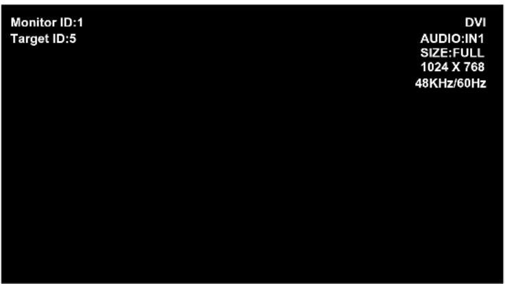
The Information OSM will be shown at top left side of the screen.
MONITOR ID: Displays the ID number of the current monitor within the daisy chain.
TARGET ID: Displays the ID number of the monitor that to be controlled via daisy chain from the current monitor.
Press the “+” or “-” buttons to change the “Target ID” to show the ID number of the monitor to be controlled. To control all of the daisy chained monitors simultaneously, select “ALL” as the “Target ID.”
NOTE: If the monitor is in ECO Standby mode, RS-232C functionality is stopped.
4. Use the wireless remote controller to control the "SECONDARY" monitor while aiming at the "PRIMARY" monitor.
The “MENU OSM” will appear on the selected target monitor.
NOTE: If the "ID No." mode select OSM is showing, press the "DISPLAY" button on the remote control while pointing at the "PRIMARY" monitor to clear this OSM.
HINT: If you lost control due to the incorrect setting of "IR CONTROL", pressing the "DISPLAY" button on the remote control for 5 or more seconds will reset the "IR CONTROL" menu to "NORMAL" function.
ID number assigned to current monitor ID number assigned monitor to be controlled via RS-232C
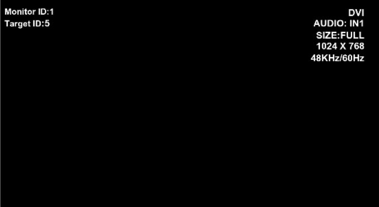
Input Source Picture Size Input Signal Information
Functions that can be controlled via RS-232C are:
- Powering ON or OFF
- Switching input signals
NOTE: If your PC (IBM or IBM compatible) is equipped only with a 25-pin serial port connector, a 25-pin serial port adapter is required. Contact your dealer for details.
NOTE: In order to function, the RS-232C OUT terminal can only be connected to another monitor of the same model. Do not connect to other types of equipment.
This LCD monitor uses RXD, TXD and GND lines for RS-232C control.
The reverse type cable (null modem cable) should be used for RS-232C control.

flowchart
graph TD
    A["PC (Out)"] --> B["IN"]
    B --> C["OUT"]
    C --> D["RS-232C Cable RS-232C Cable"]
    D --> E["RS-232C OUT"]
    E --> F["RS-232C IN"]
    F --> G["RS-232C OUT"]
    G --> H["RS-232C OUT"]
    H --> I["RS-232C IN"]
    I --> J["RS-232C OUT"]
    J --> K["RS-232C OUT"]
    K --> L["RS-232C IN"]
    L --> M["RS-232C OUT"]
    M --> N["RS-232C IN"]
    N --> O["RS-232C OUT"]
    O --> P["RS-232C IN"]
    P --> Q["RS-232C OUT"]
    Q --> R["RS-232C IN"]
    R --> S["RS-232C OUT"]
    S --> T["RS-232C IN"]
    T --> U["RS-232C OUT"]
    U --> V["RS-232C IN"]
    V --> W["RS-232C OUT"]
    W --> X["RS-232C IN"]
    X --> Y["RS-232C OUT"]
    Y --> Z["RS-232C IN"]
    Z --> AA["RS-232C OUT"]
    AA --> AB["RS-232C IN"]
    AB --> AC["RS-232C OUT"]
    AC --> AD["RS-232C IN"]
    AD --> AE["RS-232C OUT"]
    AE --> AF["RS-232C IN"]
    AF --> AG["RS-232C OUT"]
    AG --> AH["RS-232C IN"]
    AH --> AI["RS-232C OUT"]
    AI --> AJ["RS-232C IN"]
    AJ --> AK["RS-232C OUT"]
    AK --> AL["RS-232C IN"]
    AL --> AM["RS-232C OUT"]
    AM --> AN["RS-232C IN"]
    AN --> AO["RS-232C OUT"]
    AO --> AP["RS-232C IN"]
    AP --> AQ["RS-232C OUT"]
    AQ --> AR["RS-232C IN"]
    AR --> AS["RS-232C OUT"]
    AS --> AT["RS-232C IN"]
    AT --> AU["RS-232C OUT"]
    AU --> AV["RS-232C IN"]
    AV --> AW["RS-232C OUT"]
    AW --> AX["RS-232C IN"]
    AX --> AY["RS-232C OUT"]
The following control sequence is used for a single Multeos display.
When using the following control commands, all of the daisy-chained monitors can be controlled at the same time from the primary monitor. However, reply and status commands will only pertain to the primary monitor, and not to the secondary monitors.
1) Interface
| PROTOCOL RS-232C | |
| BAUD RATE 9600 [ops] | |
| DATA LENGTH 8 [bits] | |
| PARITY BIT NONE | |
| STOP BIT 1 [bit] | |
| FLOW CONTROL NONE | |
2) Control command diagram
The command is structured by the address code, function code, data code and end code. The length of the command is different for each function.
| Address Code Function Code Data Code End Code | ||||
| HEX 30h 30h | Function | Data 0Dh | ||
| ASCII '0' '0' | Function | Data | ||
[Address code] 30h 30h (In ASCII code, '0' '0') fixed.
[Function code] A code of each fixed control move.
[Data code] A code of each fixed control data (number) and not always indicated.
[End code] 0Dh (In ASCII code, '←') fixed.
To control multiple Multeos monitors that are daisy-chained together please use the extended control command. Instructions for the extended control command can be found on the CD included with the display. The file is called "External_control_M4X.pdf".
3) Control sequence
1) The command from a computer to the LCD monitor will take 400ms.
2) The LCD monitor will send a return command 400ms* after it has received an encode. If the command is not received correctly, the LCD monitor will not send the return command.
3) The personal computer checks the command and confirms if the command which has been sent has been executed or not.
4) This LCD monitor sends various codes other than the return code. When sending a control sequence via RS-232C, other codes from personal computers will be ignored.
*The sending time of the return command may be delayed depending on the monitor's current activity (changing of the input signal, etc.).
[Example] Turn the power ON. ( ' ' is for ASCII code)
| Sending commands from the PC etc. | Status code from LCD monitor | Meaning |
| 30 30 21 0D '0' '0' !!' | Command for POWER ON | |
| 30 30 21 0D '0' '0' !!' | Command received (Command echo back) |
4) Operation commands
Operation commands execute the basic operation setting of this LCD monitor. It may not operate when changing the signal:
| Operation ASCII HEX | ||
| POWER ON ! 21h | ||
| POWER OFF " 22h | ||
| DVI | _r1 | 5Fh 72h 31h |
| VGA | _r2 | 5Fh 72h 32h |
| RGB/HV | _r3 | 5Fh 72h 33h |
| HDMI | _h1 | 5Fh 68h 31h |
| VIDEO AV | _v1 | 5Fh 76h 31h |
| DVD/HD AV | _v2 | 5Fh 76h 32h |
| S-VIDEO AV | _v3 | 5Fh 76h 33h |
| TV DTV | _t2 | 5Fh 74h 32h |
- POWER OFF command should not be used less than 1 minute after the power is turned on.
- POWER ON command should not be used less than 1 minute after the power is turned off.
- S-VIDEO is enabled by having an S-VIDEO cable connected with the "S-VIDEO" signal present and selecting "PRIORITY MODE".
5) Read command
Host computer sends the command without Data-code to monitor.
After receiving this command, the monitor returns the command with Data-code of current status to host computer.
| Command from computer | Command from Monitor | Detail of command |
| 30 30 76 50 0D‘0”0”v”P’[enter] | Ask about the power status of monitor. | |
| 30 30 76 50 31 0D‘0”0”v”1’[enter] | Monitor is powered-on. |
Structure of the Read-command
| ASCII HEX | ||||||
| Function Data (Receive) Function Data (Receive) | ||||||
| POWER | ON vP 1 76 50 31 | |||||
| OFF (stand by) vP 0 76 | 50 30 | |||||
| Input | DVI (DVI-D) vl r1 76 49 | 72 31 | ||||
| VGA (D-sub) vl r2 76 49 | 72 32 | |||||
| RGB/HV (BNC) | vl r3 76 49 72 33 | |||||
| HDMI | vl h1 | 76 49 68 31 | ||||
| VIDEO AV | vl v1 | 76 49 76 31 | ||||
| DVD/HD AV | vl v2 | 76 49 76 32 | ||||
| S-VIDEO AV | vl v3 | 76 49 76 33 | ||||
| TV OTV | vl t2 76 49 74 32 | |||||
| Picture Mode | HIGHBRIGHT | vM | p1 76 4D | 70 31 | ||
| Standard | vM | p2 76 4D | 70 32 | |||
| Internal Temperature of Monitor | Around AV Board | resolution 0.5°C | tcx1 | (ex.)+25.0 | 74 63 78 31 | 2B 20 32 35 2E 30 |
| resolution 1°C | tc1 | (ex.)+25 | 74 63 31 | 2B 20 32 35 | ||
| Around Power PCB | resolution 0.5°C | tcx2 | (ex.)+30.5 | 74 63 78 32 | 2B 20 33 30 2E 35 | |
| resolution 1°C | tc2 | (ex.)+31 | 74 63 32 | 2B 20 33 31 | ||
NOTE: For complete information please see file "External_Control_M4X.pdf" on the CD-ROM.
RS-232C control will not function if the display is in “ECO STANDBY” mode. If monitors are daisy-chained, and one display is in “ECO STANDBY mode, then control of the entire daisy-chain will be lost. See page 30 for more information on STANDBY mode.
40" or 46" diagonal screen size: Adds a new dimension to information display technology.
1920 x 1080 resolution: Allows for crisp text and precise images.
XtraView ^® technology: Allows for wide-angle viewing.
DDC/CI capabilities: Allow control commands to be sent directly to the monitor through a standard PC or over an existing network by a system administrator.
CableComp™: Automatic long cable compensation prevents image quality degradation caused by long cable lengths.
User-friendly, efficient design: Features the currently proposed VESA-standard mounting and an overall lightweight construction for easy transport and installation.
Low power consumption and reduced heat emission: Lead to a lower total cost of ownership.
On Screen Manager (OSM®): Puts you in complete control of display settings.
NEC's quality and reliability: Provide peace of mind with a 3-year warranty (including backlight) and 24/7 customer service and technical support.
Reduced Footprint: Provides the ideal solution for environments requiring superior image quality but with size and weight reductions. The monitor's small footprint and low weight allow it to be moved or transported easily from one location to another.
AccuColor® Control System: Along with sRGB allows you to change between the color settings on your display to match your personal preference.
OmniColor™ Control System: Along with sRGB color-matching uses 6-axis color data to ensure true-to-life color reproduction for still images and real-time videos.
Plug and Play: The Microsoft ^® solution with the Windows ^® operating system facilitates setup and installation by allowing the monitor to send its capabilities (such as screen size and resolutions supported) directly to your computer, automatically optimizing display performance.
Intelligent Power Manager (IPM ^® ) System: Provides innovative power-saving methods, saving two-thirds of your monitor energy costs.
Multiple Frequency Technology: Automatically adjusts monitor to the display card's scanning frequency, thus displaying the resolution required.
FullScan® Capability: Allows you to use the entire screen area in most resolutions, significantly expanding image size.
VESA® Standard Mounting Interface: Allows users to connect their LCD monitor to any VESA standard third party mounting arm or bracket. Allows for the monitor to be mounted on a wall or an arm using any third party compliant device. NEC recommends using mounting interface that comply with UL1678 standard in North America.
DVI-D: The digital-only subset of DVI created by the Digital Display Working Group (DDWG) for digital connections between computers and displays. As a digital-only connector, analog support is not provided off a DVI-D connector. As a DVI-based digital only connection, only a simple adapter is necessary for compatibility between DVI-D and other DVI-based digital connectors such as DFP and P&D.
TILE MATRIX with TILE COMP: Allows multiple screens to display one image tiled over several stacked monitors while compensating within the displayed image for monitor bezel width.
ZOOM: Expands the image horizontally and vertically direction.
RS-232C daisy chain: You can control multiple monitors by PC or wireless remote control.
Self-diagnosis: If an internal error should occur, a failure state will be indicated by a blinking red light on the front of the monitor.
No picture
- The signal cable should be properly connected to the display card/computer.
- The display card should be properly seated in its slot.
- Front Power Switch and computer power switch should be in the ON position.
- Check to make sure that a supported mode has been selected on the display card or system being used. (Please consult display card or system manual to change graphics mode.)
- Check the monitor and your display card with respect to compatibility and recommended settings.
- Check the signal cable connector for bent or pushed-in pins.
Power Button does not respond
- Unplug the power cord of the monitor from the AC outlet to turn off and reset the monitor.
Image persistence
- Please be aware that LCD Technology may experience a phenomena known as Image Persistence. Image Persistence occurs when a residual or “ghost” image of a previous image remains visible on the screen. Unlike CRT monitors, LCD monitors’ image persistence is not permanent, but constant images being displayed for a long period of time should be avoided. To alleviate image persistence, turn off the monitor for as long as the previous image was displayed. For example, if an image was on the monitor for one hour and a residual image remains, the monitor should be turned off for one hour to erase the image.
NOTE: As with all personal display devices, NEC Display Solutions of America, Inc. recommends displaying moving images and using a moving screen saver at regular intervals whenever the screen is idle or turning off the monitor when not in use.
Image is unstable, unfocused or swimming is apparent
- Signal cable should be properly attached to the LCD monitor, computer, or other input device.
- Use the OSM screen controls to focus and adjust display by increasing or decreasing the clock phase total. When the display mode is changed, the OSM Image Adjust settings may need to be readjusted.
- Check the monitor and your display card with respect to compatibility and recommended signal timings.
- If your text is garbled, change the video mode to non-interlaced and use 60Hz refresh rate.
Image of component signal is greenish
- Check to see if the DVD/HD input connector is selected.
LED on monitor is not lit
(no green or red color can be seen)
- Main Power Switch should be in the ON position and power cord should be connected.
- Make certain the computer is not in a power-saving mode (touch the keyboard or mouse).
Red LED on monitor is blinking
- A certain failure might have occurred, please contact your nearest authorized NEC DISPLAY SOLUTIONS service facility.
Display image is not sized properly
- Use the OSM screen controls to increase or decrease the clock total.
- Check to make sure that a supported mode has been selected on the display card or system being used. (Please consult display card or system manual to change graphics mode.)
Selected resolution is not displayed properly
- Use OSM information to enter Information menu and confirm that the appropriate resolution has been selected. If not, select appropriate resolution.
"SCHEDULE SETTINGS" / "OFF TIMER"
functions not working properly
- The "SCHEDULE SETTINGS" function will be disabled when the "OFF TIMER" is set.
- If the "OFF TIMER" function is enabled and the power to the LCD monitor is turned off or if the power supply is interrupted unexpectedly, then the OFF TIMER will be reset.
No Sound
- Check to see if speaker cable is properly connected.
- Check to see if mute is activated.
- Check to see if volume is set at minimum.
NOTE: It is possible to play audio from a source that is different from the video source. When setting parental controls for video, be aware that this content is not filtered.
RS-232C does not work
- Make sure the monitor is not in "Eco Standby" mode. (see page 30)
Remote Control does not work
• Make sure the batteries are inserted properly.
• Test the batteries for strength/life.
- Make sure to point the remote directly at the sensor on the monitor.
- Check if the remote is in Remote ID mode.
- The remote control may not function when in direct sunlight or when there is strong illumination on the remote sensor of the monitor.
PIP (Picture In Picture) does not work
- Check the resolution of the input signal. PIP does not work with all types of "1080i" input signals. The PIP function will work with 1080p signals.
Snowy Picture, Poor Sound in TV
- Check antenna/cable connection. Use new cable if necessary.
Interference in TV
- Check components for shielding. Move them away from the monitor if necessary.
NEC Monitor Customer Service & Support
Customer Service and Technical Support: (800) 632-4662
Fax: (800) 695-3044
Parts and Accessories/Macintosh Cable Adapter: (800) 632-4662
Warranty Information: www.necdisplay.com
Online Technical Support: www.necdisplay.com
Sales and Product Information
Sales Information Line: (888) 632-6487
Canadian Customers: (866) 771-0266, Ext#: 4037
Government Sales: (800) 284-6320
Government Sales email: gov@necdisplay.com
Electronic Channels
World Wide Web: www.necdisplay.com
Product Registration: www.necdisplay.com
European Operations: www.nec-display-solutions.com
Drivers and Downloads: www.necdisplay.com
| LCD Module (40" / 102.0 cm diagonal) | |||||
| Pixel Pitch: 0.461 mm | |||||
| Resolution: 1920 x 1080 pixels | |||||
| Color: Over 16 million colors (depending on video card used) | |||||
| Brightness: 450cd/m² (typ) | |||||
| Contrast Ratio 1000:1 (typ) | |||||
| Viewing Angle Up 89 / Down 89 / Left 89 / Right 89 (typ) @ CR >10 | |||||
| Frequency Horizontal ANALOG: 15.625/15.734kHz, 31.5kHz - 91.1kHz DIGITAL: 31.5kHz - 91.1kHz | |||||
| Pixel Clock 25.2MHz - 162.0MHz | |||||
| Viewable Size: 885.6 x 498.2mm | |||||
| Input Signal | DVI DVI-D 24 | PIN DIGITAL RGB | DVI (HDCP) | ||
| VGA60, SVGA60, XGA60, WXGA60, SXGA60, UXGA60", 1920X1080 (60Hz) | |||||
| VGA 15 Pin Mini D-sub | Analog RGB | 0.7V p-p, Input Impedance 75 ohm | |||
| VGA60, SVGA60, XGA60, WXGA60, SXGA60, UXGA60", 1920X1080 (60Hz) | |||||
| Sync | Separate: TTL level (Pos./Neg.) | ||||
| Composite sync on Green Video: 0.3Vp-p Neg. | |||||
| RGB/HV BNC (R,G,B,H,V) | Analog RGB | 0.7V p-p, Input Impedance 75 ohm | |||
| VGA60, SVGA60, XGA60, WXGA60, SXGA60, UXGA60", 1920X1080(60Hz) | |||||
| Sync | Separate: TTL level (Pos./Neg.) | ||||
| Composite sync on Green Video: 0.3Vp-p Neg. | |||||
| HDMI | HDMI Type-A | Digital RGB | HDMI | ||
| 1080p,1080i,720p 50Hz/60Hz, 576p, 480p | |||||
| DVD/HD | RCA (Y, Cb/Pb, Cr/Pr) | Component | Y: 1.0Vp-p/75ohm, Cb/Cr (Pb/Pr): 0.7Vp-p/75 ohm | ||
| HDTV/DVD:1080p,1080i,720p 50Hz/60Hz, 576p, 480p, 576i, 480i | |||||
| VIDEO | BNC | Composite | 1.0V p-p Input Impedance 75 ohm | ||
| RCA | NTSC/PAL/SECAM/4.43NTSC/PAL60 | ||||
| S-VIDEO | DIN 4 pin | S-VIDEO | Y: 1.0Vp-p/75ohm C: 0.286Vp-p/75 ohm | ||
| NTSC/PAL/SECAM/4.43NTSC/PAL60 | |||||
| TV | 75 ohm F-terminal | Analog Terrestrial broadcast | NTSC: VHF(2-13ch).UHF(14-69ch) | ||
| Analog Cable | CATV 1-130ch | ||||
| Digital Terrestrial broadcast | ATSC (8VSB): 2-69ch | ||||
| Digital Cable | 64/256 QAM: 1-135ch | ||||
| Output Signal | RGB/HV | BNC (R,G,B,H,V) | Analog RGB | Analog RGB Video: 0.7V p-p with 75 ohm terminated Separate HV sync: TTL level (Pos./Neg.) with 2.2k ohm terminated | |
| VIDEO | BNC | COMPOSITE | Output, Composite 1.0V p-p with 75 ohm terminated | ||
| Audio | AUDIO Input | RCA (L/R) x 2 | Analog Audio | Stereo L/R 0.5Vrms/more than 22K ohm | |
| STEREO Mini Jack | |||||
| HDMI Type-A | DIGITAL Audio PCM | 32.44.1.48KHz (16bit) | |||
| AUDIO Output | STEREO Mini Jack | Analog Audio | RCA PIN-JACK L/R: 1 Output, 0.5Vrms with 1k ohm terminated | ||
| Optical S/PDIF connector | Digital Audio | S/PDIF Optical Digital audio output (PCM/Dolby Digital)** | |||
| Speaker Output | External Speaker Jack 15W + 15W (8 ohm) | ||||
| Control | RS-232C: IN | 9 Pin Mini D-sub | |||
| RS-232C: OUT | 9 Pin Mini D-sub (daisy chain) | ||||
| Power Supply | 3.0-1.2A@100-240V AC, 50/60Hz | ||||
| Operational Environment | Temperature | 5°C to 40°C/41°F to 104°F | |||
| Humidity | 10% to 80% | ||||
| Storage Environment | Temperature | -20°C to 60°C/-4°F to 140°F | |||
| Humidity | 10% to 90% (without condensation) / below 60% over 40°C | ||||
| Dimensions | Net | 981.8 (W) x 627.9 (H) x 400 (D) mm (with Stand) 981.8 (W) x 582.4 (H) x 142.5 (D) mm (without Stand) 627.4 (W) x 981.8 (H) x 142.5 (D) mm (Portrait mode without Stand) | |||
| Gross | 1147.0 (W) x 780.0 (H) x 540.0 (D) mm | ||||
| Weight | Net | 32.6kg / 71.9 lbs. | |||
| Gross | 41.9kg / 92.4 lbs. | ||||
| VESA compatible arm mounting interface | 3 x 200mm x 200mm (8 Holes) | ||||
| 2 x 200mm x 200mm (6 Holes) | |||||
| Compiled Regulatory and Guidelines | UL 60950-1/CSA C22.2 No.60950-1/ TUV-GS/EN60950-1 FCC-B/DOC-B/EN55022-A/EN55024/EN61000-3-2/EN61000-3-3/CE | ||||
| Power Management | VESA DPM | ||||
| Plug & Play | VESA DDC2B DDC/CI | ||||
| Accessories | User's manual, Power Cord, Video Signal Cable, Remote Control, AA Battery x 2, Clamp x 3, Screw x 5, CD-ROM, Main switch cover x 1 | ||||
*Compressed Image
**Audio Output for Digital Terrestrial broadcast
Manufactured under license from Dolby Laboratories. "Dolby" and the double-D symbol are trademarks of Dolby Laboratories.
Specifications M46
| LCD Modulc (46" / 116.8 cm diagonal) | |||||
| Pixel Pitch 0.530 mm | |||||
| Resolution 1920 x 1080 pixels | |||||
| Color Over 16 million colors (depending on video card used) | |||||
| Brightness 450cd/m² (typ) | |||||
| Contrast Ratio 1200:1 (typ) | |||||
| Viewing Angle Up 89 / Down 89 / Left 89 / Right 89 (typ) @ CR >10 | |||||
| Frequency Horizontal ANALOG: 15,625/15.734kHz, 31.5kHz - 91.1kHz DIGITAL: 31.5kHz - 91.1kHz | |||||
| Pixel Clock 25.2MHz - 162.0MHz | |||||
| Viewable Size 1018.1 x 572.7mm | |||||
| Input Signal | DVI DVI-D 2# PIN DIGITAL RGB | DVI (HDCP) | |||
| VGA60, SVGA60, XGA60, WXGA60, SXGA60, UXGA60*, 1920X1080 (60Hz) | |||||
| VGA 15 Pin Mini D-sub | Analog RGB | 0.7V p-p, Input Impedance 75 ohm | |||
| VGA60, SVGA60, XGA60, WXGA60, SXGA60, UXGA60*, 1920X1080 (60Hz) | |||||
| Sync | Separate: TTL level (Pos./Neg.) | ||||
| Composite sync on Green Video: 0.3Vp-p Neg. | |||||
| RGB/HV BNC (R,G,B,H,V) | Analog RGB | 0.7V p-p, Input Impedance 75 ohm | |||
| VGA60, SVGA60, XGA60, WXGA60, SXGA60, UXGA60*, 1920X1080(60Hz) | |||||
| Sync | Separate: TTL level (Pos./Neg.) | ||||
| Composite sync on Green Video: 0.3Vp-p Neg. | |||||
| HDMI | HDMI Type-A | Digital RGB | HDMI | ||
| 1080p,1080i,720p 50Hz/60Hz, 576p, 480p | |||||
| DVD/HD | RCA (Y, Cb/Pb, Cr/Pr) | Component | Y: 1.0Vp-p/75ohm, Cb/Cr (Pb/Pr): 0.7Vp-p/75 ohm | ||
| HDTV/DVD:1080p,1080i,720p 50Hz/60Hz, 576p, 480p, 576i, 480i | |||||
| VIDEO | BNC | Composite | 1.0V p-p Input Impedance 75 ohm | ||
| RCA | NTSC/PAL/SECAM/4.43NTSC/PAL60 | ||||
| S-VIDEO | DIN 4 pin | S-VIDEO | Y: 1.0Vp-p/75ohm C: 0.286Vp-p/75 ohm | ||
| NTSC/PAL/SECAM/4.43NTSC/PAL60 | |||||
| TV | 75 ohm F-terminal | Analog Terrestrial broadcast | NTSC: VHF(2-13ch),UHF(14-69ch) | ||
| Analog Cable | CATV 1-130ch | ||||
| Digital Terrestrial broadcast | ATSC (8VSB):2-69ch | ||||
| Digital Cable | 64/256 QAM : 1-135ch | ||||
| Output Signal | RGB/HV | BNC (R,G,B,H,V) | Analog RGB | Analog RGB Video: 0.7V p-p with 75 ohm terminated Separate HV sync: TTL level (Pos./Neg.) with 2.2k ohm terminated | |
| VIDEO | BNC | COMPOSITE | Output, Composite 1.0V p-p with 75 ohm terminated | ||
| Audio | AUDIO Input | RCA (L/R) x 2 | Analog Audio | Stereo L/R 0.5Vrms/more than 22K ohm | |
| STEREO Mini Jack | |||||
| HDMI Type-A | DIGITAL Audio PCM 32, 44.1, 48KHz (10bit) | ||||
| AUDIO Output | STEREO Mini Jack | Analog Audio | RCA PIN-JACK L/R: 1 Output, 0.5Vrms with 1k ohm terminated | ||
| Optical S/PDIF connector | Digital Audio | S/PDIF Optical Digital audio output (PCM/Dolby Digital)** | |||
| Speaker Output | External Speaker Jack 15W + 15W (8 ohm) | ||||
| Control | RS-232C: IN | 9 Pin Mini D-sub | |||
| RS-232C: OUT | 9 Pin Mini D-sub (daisy chain) | ||||
| Power Supply | 3.4-1.35A@100-240V AC, 50/60Hz | ||||
| Operational Environment | Temperature | 5°C to 40°C/41°F to 104°F | |||
| Humidity | 10% to 80% | ||||
| Storage Environment | Temperature | -20°C to 60°C/-4°F to 140°F | |||
| Humidity | 10% to 90% (without condensation) / below 60% over 40°C | ||||
| Dimensions | Net | 1112.8 (W) x 704.8 (H) x 400 (D) mm (with Stand) 1112.8 (W) x 659.4 (H) x 142.5 (D) mm (without Stand) 659.4 (W) x 1112.8 (H) x 142.5 (D) mm (Portrait mode without Stand) | |||
| Gross | 1278.0 (W) x 875.0 (H) x 540.0 (D) mm | ||||
| Weight | Net | 39.3kg / 86.6 lbs. | |||
| Gross | 49.7kg / 109.6 lbs. | ||||
| VESA compatible arm mounting Interfaces | 3 x 200mm x 200mm (8 Holes) | ||||
| 2 x 200mm x 200mm (6 Holes) | |||||
| Complied Regulatory and Guidelines | UL 60950-1/CSA C22.2 No.60950-1/ TUV-GS/EN60950-1 FCC-B/DOC-B/EN55022-A/EN55024/EN61000-3-2/EN61000-3-3/CE | ||||
| Power Management | VESA DPM | ||||
| Plug & Play | VESA DDC2B DDC/CI | ||||
| Accessories | User's manual, Power Cord, Video Signal Cable, Remote Control, AA Battery x 2, Clamp x 3, Screw x 5, CD-ROM, Main switch cover x 1 | ||||
*Compressed Image
**Audio Output for Digital Terrestrial broadcast
Manufactured under license from Dolby Laboratories. "Dolby" and the double-D symbol are trademarks of Dolby Laboratories.
Pin Assignment
1) Analog RGB Input (Mini D-SUB 15P) VGA
| Pin No. | Name |
| 1 | Video Signal Red |
| 2 | Video Signal Green |
| 3 | Video Signal Blue |
| 4 | GND |
| 5 | DDC-GND |
| 6 | Red-GND |
| 7 | Green-GND |
| 8 | Blue-GND |
| 9 | +5V (DDC) |
| 10 | SYNC-GND |
| 11 | GND |
| 12 | DDC-SDA |
| 13 | H-SYNC |
| 14 | V-SYNC |
| 15 | DDC-SCL |
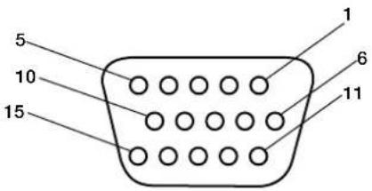
Mini D-SUB 15P
3) RS-232C Input (Mini D-SUB 9P)
| Pin No. | Name |
| 1 | Connected to 7 & 8 |
| 2 | RXD |
| 3 | TXD |
| 4 | Connected to 6 |
| 5 | GND |
| 6 | Connected to 4 |
| 7 | Connected to 1 & 8 |
| 8 | Connected to 1 & 7 |
| 9 | NC |

Mini D-SUB 9P
2) Digital RGB Input (DVI-D) DVI
| 1 | TX2- 9 TX1- 17 TX0- | ||||
| 2 | TX2+ 10 TX1+ 18 TX0+ | ||||
| 3 | Shield (TX2/TX4) 11 | Shield (TX1/TX3) 19 Shield (TXP/TX5) | |||
| 4 | NC 12 NC 20 NC | ||||
| 5 | NC 13 NC 21 NC | ||||
| 6 | DDC-Serial Clock 14 | +5 power | 22 | Shield (TXC) | |
| 7 | DDC-Serial Data | 15 Ground (+5V) | 23 | TXC+ | |
| 8 | NC 16 Hot Plug Detect | 24 TXC- | |||

Limited Warranty
NEC Display Solutions of America, Inc. (hereinafter “NEC DISPLAY SOLUTIONS”) warrants this Product to be free from defects in material and workmanship and, subject to the conditions set forth below, agrees to repair or replace (at NEC DISPLAY SOLUTIONS’ sole option) any part of the enclosed unit which proves defective for a period of three (3) years from the date of first consumer purchase. Spare parts are warranted for ninety (90) days. Replacement parts or unit may be new or refurbished and will meet specifications of the original parts or unit.
This warranty gives you specific legal rights and you may also have other rights, which vary from state to state. This warranty is limited to the original purchaser of the Product and is not transferable. This warranty covers only NEC DISPLAY SOLUTIONS-supplied components. Service required as a result of third party components is not covered under this warranty. In order to be covered under this warranty, the Product must have been purchased in the U.S.A. or Canada by the original purchaser. This warranty only covers Product distribution in the U.S.A. or Canada by NEC DISPLAY SOLUTIONS No warranty service is provided outside of the U.S.A. or Canada. Proof of Purchase will be required by NEC DISPLAY SOLUTIONS to substantiate date of purchase. Such proof of purchase must be an original bill of sale or receipt containing name and address of seller, purchaser, and the serial number of the product.
It shall be your obligation and expense to have the Product shipped, freight prepaid, or delivered to the authorized reseller from whom it was purchased or other facility authorized by NEC DISPLAY SOLUTIONS to render the services provided hereunder in either the original package or a similar package affording an equal degree of protection. All Products returned to NEC DISPLAY SOLUTIONS for service MUST have prior approval, which may be obtained by calling 1-800-632-4662. The Product shall not have been previously altered, repaired, or serviced by anyone other than a service facility authorized by NEC DISPLAY SOLUTIONS to render such service, the serial number of the product shall not have been altered or removed. In order to be covered by this warranty the Product shall not have been subjected to displaying of fixed images for long periods of time resulting in image persistence (afterimage effects), accident, misuse or abuse or operated contrary to the instructions contained in the User's Manual. Any such conditions will void this warranty.
NEC DISPLAY SOLUTIONS SHALL NOT BE LIABLE FOR DIRECT, INDIRECT, INCIDENTAL, CONSEQUENTIAL, OR OTHER TYPES OF DAMAGES RESULTING FROM THE USE OF ANY NEC DISPLAY SOLUTIONS PRODUCT OTHER THAN THE LIABILITY STATED ABOVE. THESE WARRANTIES ARE IN LIEU OF ALL OTHER WARRANTIES EXPRESS OR IMPLIED, INCLUDING, BUT NOT LIMITED TO, THE IMPLIED WARRANTIES OF MERCHANTABILITY OR FITNESS FOR A PARTICULAR PURPOSE. SOME STATES DO NOT ALLOW THE EXCLUSION OF IMPLIED WARRANTIES OR THE LIMITATION OR EXCLUSION OF LIABILITY FOR INCIDENTAL OR CONSEQUENTIAL DAMAGES SO THE ABOVE EXCLUSIONS OR LIMITATIONS MAY NOT APPLY TO YOU.
This Product is warranted in accordance with the terms of this limited warranty. Consumers are cautioned that Product performance is affected by system configuration, software, the application, customer data, and operator control of the system, among other factors. While NEC DISPLAY SOLUTIONS Products are considered to be compatible with many systems, specific functional implementation by the customers of the Product may vary. Therefore, suitability of a Product for a specific purpose or application must be determined by consumer and is not warranted by NEC DISPLAY SOLUTIONS.
For the name of your nearest authorized NEC Display Solutions of America, Inc. service facility, contact NEC Display Solutions of America, Inc. at 1-800-632-4662.
Manufacturer's Recycling and Energy Information
NEC DISPLAY SOLUTIONS is strongly committed to environmental protection and sees recycling as one of the company's top priorities in trying to minimize the burden placed on the environment. We are engaged in developing environmentally-friendly products, and always strive to help define and comply with the latest independent standards from agencies such as ISO (International Organization for Standardization) and TCO (Swedish Trades Union).
Disposing of old NEC product
The aim of recycling is to gain environmental benefits by means of reusing, upgrading, reconditioning, or reclaiming old material. Dedicated recycling sites ensure that environmentally harmful components are properly handled and securely disposed. To ensure the best recycling of our products, NEC DISPLAY SOLUTIONS offers a variety of recycling procedures and gives advice on how to handle the product, in an environmentally sensitive way, once it has reached the end of its life.
All required information concerning the disposal of the product and country-specific information can be found on our following websites:
USA: http://www.necdisplay.com
Europe: http://www.nec-display-solutions.com/greencompany/
Japan: http://www.nec-display.com
Energy saving
This monitor features an advanced energy saving capability. When a VESA Display Power Management Signaling (DPMS) Standard signal is sent to the monitor, the Energy Saving mode is activated. The monitor enters a single Energy Saving mode.
M40
| Mode Power consumption LED color | |
| Normal Operation Approx. 300W Green | |
| Energy Saving Mode Less than 5W Amber | |
| Off Mode Less than 1W Unlit |
M46
| Mode Power consumption LED color | |
| Normal Operation Approx. 340W Green | |
| Energy Saving Mode Less than 5W Amber | |
| Off Mode Less than 1W Unlit |
WEEE Mark (European Directive 2002/96/EC)
Within the European Union
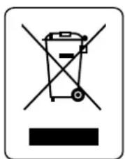
EU-wide legislation, as implemented in each Member State, requires that waste electrical and electronic products carrying the mark (left) must be disposed of separately from normal household waste. This includes monitors and electrical accessories, such as signal cables or power cords. When you need to dispose of your NEC display products, please follow the guidance of your local authority, or ask the shop where you purchased the product, or if applicable, follow any agreements made between yourself and NEC. The mark on electrical and electronic products only applies to the current European Union Member States.
The mark on electrical and electronic products only applies to the current European Union Member States.
Outside the European Union
If you wish to dispose of used electrical and electronic products outside the European Union, please contact your local authority so as to comply with the correct disposal method.
aVErtiSSEMENT

AFIN D'ÉVITER TOUT RISQUE D'INCENDIE ET D'ÉLECTROCUTION, NE PAS EXPOSER CET APPAREIL À LA PLUIE OU À L'HUMIDITÉ. NE PAS UTILISER LA FICHE POLARISÉE DE L'APPAREIL AVEC UNE PRISE DE COURANT DOTÉE D'UNE RALLONGE OU AUTRE PRISE À MOINS QUE LES BROCHES PUISSENT Y ÊTRE COMPLÈTEMENT INTRODUITES. LE BOÎTIER DE L'APPAREIL CONTIENT DES COMPOSANTS À HAUTE TENSION ET NE DOIT EN AUCUN CAS ÊTRE OUVERT. TOUT TRAVAIL D'ENTRETIEN DOIT ÊTRE CONFIÉ À UN TECHNICIEN QUALIFIÉ.

attEntion
ATTENTION:

ATTENTION : POUR RÉDUIRE LE RISQUE DE CHOC ÉLECTRIQUE, S'ASSURER QUE LE CORDON D'ALIMENTATION EST DÉBRANCHÉ DE LA PRISE MURALE. POUR SUPPRIMER COMPLÈTEMENT L'ALIMENTATION DE L'APPAREIL, DÉBRANCHER LE CORDON D'ALIMENTATION DE LA PRISE CA. NE PAS RETIRER LE COUVERCLE (NI LE PANNEAU ARRIÈRE). AUCUN ÉLÉMENT UTILISABLE PAR L'UTILISATEUR À L'INTÉRIEUR. TOUT TRAVAIL D'ENTRETIEN DOIT ÊTRE CONFIÉ À UN TECHNICIEN QUALIFIÉ.
NEC Display Solutions
Systems Corporation
4-13-23, Shibaura, Minato-Ku
Tokyo 108-0023, Japan
American National Standard for Human Factors Engineering of Visual Display Terminal Workstations ANSI-HFS Standard No. 100-1988
natural_image
Illustration of a flat-screen computer monitor with a stand (no text or symbols visible)natural_image
Coiled electrical plug with two terminal connectors (no text or symbols visible)natural_image
Front view of a NBC remote control with two rolled-up cable illustrations beside it (no text or symbols visible)Installation (suite)
natural_image
Technical line drawing of a mechanical assembly with mounting holes and a curved component (no text or symbols)3) Exigences de ventilation
Figure 6

natural_image
Diagram showing a mechanical assembly with a magnified inset of a component (no text or symbols visible)natural_image
Mechanical assembly diagram showing a component with an arrow pointing to a magnified view of a bracket (no text or symbols present)3) PICTURE MODE (MODE IMAGE)
12) PIP (IMAGE sur IMAGE)
natural_image
Three technical diagrams showing a vehicle's rear door, front panel, and side view with arrows indicating movement (no text or symbols present)Branchements (suite)
WEEE Mark (Directive Européenne 2002/96/EC)
DÉCLARATION DE CONFORMITÉ
NEC Display Solutions
Systems Corporation
4-13-23, Shibaura,
Minato-Ku
Tokyo 108-0023, Japan
American National Standard for Human Factors Engineering of Visual Display Terminal Workstations ANSI-HFS Standard No. 100-1988
Publicado por:
The Human Factors and Ergonomics Society P.O. Box 1369, Santa Monica, California 90406.
natural_image
Illustration of a flat-screen monitor with a stand (no text or symbols visible)natural_image
Coiled electrical plug with two terminal connectors (no text or symbols visible)Manual del usuario
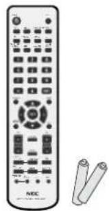
natural_image
Illustration of a NBC remote control with scroll beside it (no text or symbols visible)natural_image
Technical line drawing of a mechanical assembly with mounting holes and a circular component (no text or symbols)Figura 6

natural_image
Technical diagram showing a mechanical assembly with an inset close-up of a component (no visible text or symbols)natural_image
Mechanical assembly diagram showing a component with an arrow pointing to a magnified view of a bracket (no text or symbols present)Monitor ID:1 Target ID:5
DVI
AUDIO:IN1
SIZE:FULL
1024 X 768
48KHz/60Hz
natural_image
Three technical diagrams showing front, side, and top views of a car with no visible text or symbols
Fuente de entrada
Tamaño de la imagen
The information disclosed in this document, including all designs and related materials, is the valuable property of NEC Display Solutions of America, Inc. and/or its licensors, as appropriate, reserve all patent, copyright and other proprietary rights to this document, including all design, manufacturing, reproduction, use and sales rights thereto, except to the extent said rights are expressly granted to others.
The NEC Display Solutions of America, Inc. product(s) discussed in this document are warranted in accordance with the terms of the Limited Warranty Statement accompanying each product. However, actual performance of each such product is dependent upon factors such as system configuration, customer data and operator control. Since implementation by customers of each product may vary, the suitability of specific product configurations and applications must be determined by the customer and is not warranted by NEC Display Solutions of America, Inc.
To allow for design and specification improvements, the information in this document is subject to change at any time without notice.
Reproduction of this document or portions thereof without prior approval of NEC Display Solutions of America, Inc. is prohibited.
DECLARATION OF CONFORMITY
This device complies with Part 15 of FCC Rules. Operation is subject to the following two conditions. (1) This device may not cause harmful interference, and (2) this device must accept any interference received, including interference that may cause undesired operation.
U.S. Responsible Party: NEC Display Solutions of America, Inc.
Address: 500 Park Blvd. Suite 1100
Itasca, IL 60143
Tel. No.: (630)467-3000
Type of Product: Computer Monitor
Equipment Classification: Class B Peripheral
Model: Multeos M40 (L406T3)
Multeos M46 (L466T4)

We hereby declare that the equipment specified above conforms to the technical standards as specified in the FCC Rules.
Windows is a registered trademark of Microsoft Corporation. NEC is a registered trademark of NEC Corporation. All other brands and product names are trademarks or registered trademarks of their respective owners.


- Caution
- Canadian Department of Communications Compliance Statement
- FCC Information
- Declaration of the Manufacturer
- Safety Precautions and Maintenance
- FOR OPTIMUM PERFORMANCE, PLEASE NOTE THE FOLLOWING WHEN SETTING UP AND USING THE MONITOR:
- Recommended Use
- CORRECT PLACEMENT AND ADJUSTMENT OF THE MONITOR CAN REDUCE EYE, SHOULDER AND NECK FATIGUE. CHECK THE FOLLOWING WHEN POSITIONING THE MONITOR:
- Ergonomics
- Cleaning the LCD Panel
- Cleaning the Cabinet
- Mounting
- For NEC Qualified Personnel:
- Please note the following when mounting on wall or ceiling.
- Mounting location
- Mounting on Ceiling
- Maintenance
- Orientation
- Attaching Mounting Accessories
- 1) Attach Mounting Accessories
- 2) Stand Removal
- 3) Ventilation Requirements
- 4) Main Power Switch Cover
- 5) Prevent Tipping
- Part Names and Functions
- Control Panel
- 1) POWER
- 2) MUTE
- 3) INPUT
- 4) PLUS (+)
- 5) MINUS (-)
- 6) UP (▲)
- 7) DOWN (▼)
- 8) EXIT
- 9) Remote control sensor and Power indicator
- 10) Main Power Switch
- Control Key Lock Mode
- Part Names and Functions - continued
- 2) INPUT
- 3) PICTURE MODE
- 4) SIZE
- 5) KEYPAD
- 6) DISPLAY
- 7) ▲ ▼
- 8) AUTO SETUP
- 9) CHANNEL RETURN DTV
- 10) VOLUME AV
- 11) STILL
- 12) PICTURE in PICTURE AV
- 13) REMOTE ID
- 14) GUIDE DTV
- 15) AUDIO INPUT AV
- 16) SOUND AV
- 17) ENTER DTV
- 18) MENU
- 19) SET
- 20) - , +
- 21) EXIT
- 22) Channel DTV
- 23) MUTE AV
- 24)
- 25) SLEEP
- 26) MTS DTV
- Changing the channel DTV
- Tuning Analog Channels
- Tuning Digital Channels
- Remote Control Operating Range
- Operating Range for the Remote Control
- Handling the Remote Control
- Remote Control ID Function
- REMOTE CONTROL ID
- TO SET REMOTE CONTROL ID:
- TO USE REMOTE CONTROL ID MODE
- Please see installation on page 6 of this manual and follow all installation instructions.
- 1) Determine the installation location.
- IMPORTANT
- 2) Install the remote control batteries.
- 3) Connect external equipment.
- 4) Connect the supplied power cord.
- 5) Switch on the power of all the attached external equipment.
- 6) Operate the attached external equipment.
- 7) Adjust the sound AV
- 8) Adjust the screen (See page 27).
- 9) Adjust the image (See page 27).
- 10) Recommended Adjustments
- Connections
- Before connecting external equipment to LCD:
- Connecting the LCD Monitor to a PC
- Connecting to a Macintosh ® Computer
- Connecting to a Computer with Digital Output
- Connecting a DVD Player with component out AV
- Connect the LCD Monitor to a DVD Player
- Connecting a DVD Player with HDMI out
- Connecting a DVD Player with SCART out AV
- Connect the LCD Monitor to a DVD Player AV
- Connecting to a Stereo Amplifier AV
- Connect the LCD Monitor to a Stereo Amplifier AV
- Basic Operation - Power ON and OFF Modes
- Power Management
- Picture Size
- Picture Mode
- Information OSM
- OSM (On-Screen Manager) Controls
- Initial TV Setup
- Parental Controls TV, VIDEO input only.
- NOTE 1: CREATING A SCHEDULE
- NOTE 2: IMAGE PERSISTENCE
- MONITOR ID and IR CONTROL
- Connect PC and M40/M46.
- Set Monitor ID and IR Control mode.
- Press the "DISPLAY" button on the remote control while aiming at the "PRIMARY" monitor.
- Use the wireless remote controller to control the "SECONDARY" monitor while aiming at the "PRIMARY" monitor.
- Functions that can be controlled via RS-232C are:
- 1) Interface
- 2) Control command diagram
- 3) Control sequence
- 4) Operation commands
- 5) Read command
- No picture
- Power Button does not respond
- Image persistence
- Image is unstable, unfocused or swimming is apparent
- Image of component signal is greenish
- LED on monitor is not lit
- (no green or red color can be seen)
- Red LED on monitor is blinking
- Display image is not sized properly
- Selected resolution is not displayed properly
- "SCHEDULE SETTINGS" / "OFF TIMER"
- functions not working properly
- No Sound
- RS-232C does not work
- Remote Control does not work
- PIP (Picture In Picture) does not work
- Snowy Picture, Poor Sound in TV
- Interference in TV
- NEC Monitor Customer Service & Support
- Specifications M46
- Pin Assignment
- Limited Warranty
- Manufacturer's Recycling and Energy Information
- Disposing of old NEC product
- Energy saving
- WEEE Mark (European Directive 2002/96/EC)
- Within the European Union
- Outside the European Union
- aVErtiSSEMENT
- attEntion
- Installation (suite)
- 3) Exigences de ventilation
- 3) PICTURE MODE (MODE IMAGE)
- 12) PIP (IMAGE sur IMAGE)
- Branchements (suite)
- WEEE Mark (Directive Européenne 2002/96/EC)
- DÉCLARATION DE CONFORMITÉ
- DECLARATION OF CONFORMITY
Brand : NEC
Model : MULTEOS M40
Category : Monitor