SFD-321B/LFHSE - Computer Accessories SAMSUNG - Free user manual and instructions
Find the device manual for free SFD-321B/LFHSE SAMSUNG in PDF.

User questions about SFD-321B/LFHSE SAMSUNG
0 question about this device. Answer the ones you know or ask your own.
Ask a new question about this device
Download the instructions for your Computer Accessories in PDF format for free! Find your manual SFD-321B/LFHSE - SAMSUNG and take your electronic device back in hand. On this page are published all the documents necessary for the use of your device. SFD-321B/LFHSE by SAMSUNG.
USER MANUAL SFD-321B/LFHSE SAMSUNG
Liaobu Town Dongguan City
Guangdong Province, China
| FLOPPY DISK DRIVE SPECIFICATION | PAGE1 | |
| MODEL | SFD-321B | |
| CONTENTS | ||
| 1. INTRODUCTION1.1Application1.2DiskUsed | ||
| 2. GENERAL SPECIFICATIONS2.1Performance2.2EnvironmentalConditions2.3Reliability2.4PowerSupply2.5PhysicalSpecifications | ||
| 3. INSTALLATION | ||
| 4. ELECTRICAL INTERFACE4.1SignalInterface4.2PowerInterface4.3InterfaceConnectors | ||
| 5. SIGNAL CHARACTERISTICS5.1SignalLevel5.2RecommendedInterfaceCircuit5.3InputSignals5.4OutputSignals | ||
| 6. TIMING DIAGRAM6.1SeekOperationTiming6.2Read/WriteOperationTiming | ||
| FLOPPY DISK DRIVE SPECIFICATION | PAGE2 | |
| MODEL | SFD-321B | |
7. SAFETY STANDARDS
8. PACKAGING DESCRIPTION
8.1 LabelDescription
8.2 Packaging Method
8.3PalletDimensionandtheMethod
9. OPTION SELECTION
9.1 TraceOptions
9.2 OtherOptions(BuyerSelection)
10. GENERAL COMMENT
※ LIST of FIGURES
Figure2-1. PhysicalDimensions(WithBezelType)
Figure 2-2. Physical Dimensions (Without Bezel Type)
Figure3-1. Installation
Figure4-1. Signal Interface Connector and Cable Side Connector
Figure4-2. PowerInterface Connector and Cable Side Connector
Figure4-3. RearViewofFDD
Figure8-1. PackagingMethod
Figure8-2. PalletDimension&Method
| FLOPPY DISK DRIVE SPECIFICATION | PAGE3 | |
| MODEL | SFD-321B |
1. INTRODUCTION
1.1 Application
This manual shall be applied for SAMSUNGSFD-321B-doubleside, dual density (option: 3 mode), 3.5 inch microfloppy disk drive (hereinafter referred to as "FDD").
1.2 Disk Used
3.5inchmicrofloppydisks(hereinafterreferredtoas"DISK"), the useofwhichwillbemutuallyagreedbetweenthecustomersand SAMSUNG, shallbeused.
| FLOPPY DISK DRIVE SPECIFICATION | PAGE4 | |
| MODEL | SFD-321B |
2. GENERAL SPECIFICATIONS
2.1 Performance
| ITEM | LOW DENSITY STANDARD 1MB | HIGH DENSITY STANDARD 2MB | HIGH DENSITY *OPTION* 1.6MB | ||
| Capacity (KBytes) | Unformatted | PerDisk100020 | 001600 | ||
| PerTrack6.2512 | 2.510.0 | ||||
| Formatted | PerDisk (Sector /Track) | 655.4 (16) | 1310.7 (32) | 1065.0 (26) | |
| 737.3 (9) | 1474.6 (18) | 1228.8 (15) | |||
| 819.2 (5) | 1638.4 (10) | 1310.7 (8) | |||
| RecordingDensity (BPI)-Inner Most Track, side 1 | 8,717 | 17,434 | 14,528 | ||
| Data Transfer Rate (KBits / sec)-MFM recording | 250 | 500 | |||
| Number of Heads | 2 | ||||
| Number of Tracks | 160 | ||||
| Track Density (TPI) | 135TPI (5.33 Tracks / mm) | ||||
| DriveMotor Specification | Rotational Speed | 300 RPM | 360 RPM | ||
| LSV | ± 1.5 % Max. | ||||
| ISV | ± 1.5 % Max. | ||||
| Start Time | 500 ms Max. | ||||
| AccessTime | Track to Track Time | 3 ms | |||
| Head Settling Time | 15 ms Max. | ||||
| Head 0 / Head 1 Offset | Head 1 is displaced 8 tracks toward the drive spindle direction. | ||||
| FLOPPY DISK DRIVE SPECIFICATION | PAGE5 | |
| MODEL | SFD-321B |
| ITEM | LOW DENSITY STANDARD 1MB | HIGH DENSITY STANDARD 2MB | HIGH DENSITY *OPTION* 1.6MB | |
| MediaOperating Force | Inserting800gr | Max. | ||
| Ejecting 1300gr | Max. | |||
| MediaEjectingDistance | 10~70mm | |||
| Acoustic Noise at 50 cm- at 3 ms Step Rate | 50dBAMax. | |||
| Read BitShift | 1300nsMax. | 650nsMax. | ||
| 1.MeasuredwithBrikon723Bon Track79 with0nsprecompensation onboth heads. | ||||
| Asymmetry | 600nsMax. | 300nsMax. | ||
| 1.MeasuredwithBrikon723Bon Track00 with0nsprecompensation onboth heads. | ||||
| Radial Alignment | Both R/W heads must be radially aligned to all tracks within ±0.0200mm when accessed from either direction. Measurementistobemade at normal voltage and normal environmental condition (23±2 °C and 50±5 %RH) | |||
| AzimuthAlignment | ±0° 18' Max. | |||
| IndextoDataBurst | 0~1300 μs Measurementistobemade from the leading edge of index pulse to the beginning of data burst on Track40. | |||
| OverwriteModulation | -26dBorlessatTrack00 | |||
*Read/WriteCompensation:125nsisrecommended
| FLOPPY DISK DRIVE SPECIFICATION | PAGE6 | |
| MODEL | SFD-321B |
2.2 Environmental Conditions
| ITEM SPECIFICATION | ||||
| Ambient Temperature | Operating(°C) | 0 ~ 50 | ||
| Storage(°C)-40 | ~ 70 | |||
| Transportation(°C)-40 | ~ 70 | |||
| TemperatureGradient (°C / Hr) | Operating | 20 Max. | ||
| Non-operating | 30 Max. | |||
| Relative Humidity(%)*No-condensation | Operating:29 °C Max. wet bulb temp. | 20 ~ 80 | ||
| Storage : 40 °C Max.wet bulbtemp. | 0 ~ 90 | |||
| Transportation: 45 °C Max.wet bulbtemp. | 0 ~ 90 | |||
| Vibration (30min.sweep cycle)*Exclude resonant frequency | Operating | 5 ~ 100 Hz frequency range | 1.5 G Max. | |
| 100~ 200 Hz frequency range | 1.0 G Max. | |||
| 200~ 600 Hz frequency range | 0.5 G Max. | |||
| Transportation: 5 ~600 Hz frequency range | 3 G Max. | |||
| Shock (11 ms half sine wave) | Operating | 5 G Max. | ||
| Transportation | 100 GMax. | |||
| FLOPPY DISK DRIVE SPECIFICATION | PAGE7 | |||
| MODEL | SFD-321B | |||
2.3 Reliability
| ITEM | SPECIFICATION | |
| M.T.B.F.(Meantimebetweenfailures) | 20000poweronhours(POH)(25%duty) | |
| M.T.T.R.(Mean time to repair) | 30 minutes Max. | |
| Component Life | 5 years | |
| DiskLife | 3 × 10^6 passespertrackormore | |
| DiskInsertion | 3 × 10^4 timesormore | |
| ErrorRate | SoftReadError(*1) | 1 per 10^9 bitsread |
| HardReadError(*2) | 1 per 10^12 bitsread | |
| SeekError(*3) | 1 per 10^6 seeks | |
(*1) A soft (recoverable) error is defined as a successful attempt to read a track of data within 3 retries after areadfailure.
A read retry is defined as an attempt to read the entire track that a read failure occurred on.
(*2)Ahard(non-recoverable)errorisdefinedasafailuretoreadatrackof datawithin3retriesafterareadfailure.
(*3) A seek (access) error is defined as the inability of the drive to seek to atargetedtrackwithin1retry.Anaccessretryisdefinedasonerecalibration withanattempttoseektothetargetedtrack.
| FLOPPY DISK DRIVE SPECIFICATION | PAGE8 | |
| MODEL | SFD-321B |
2.4 Power Supply
| ITEM SPECIFICATION | |||
| RequiredPowerD.C.5V | ± 10 % | ||
| Allowable Ripple Voltage | 100 mVp-p (includingspikenoise) | ||
| Power Consumption | OperatingMode | AverageCurrent | AveragePower |
| Typ. | Typ. | ||
| Stand - by | 2 mA | 10mW | |
| Read Operation | 0.3 A | 1.5 W | |
| WriteOperation | 0.3A | 1.5W | |
| SeekOperation(3ms) | 0.7A | 3.5W | |
| DriveMotorStart | 0.7A | 3.5W | |
+5 V(*1)
Current(A)
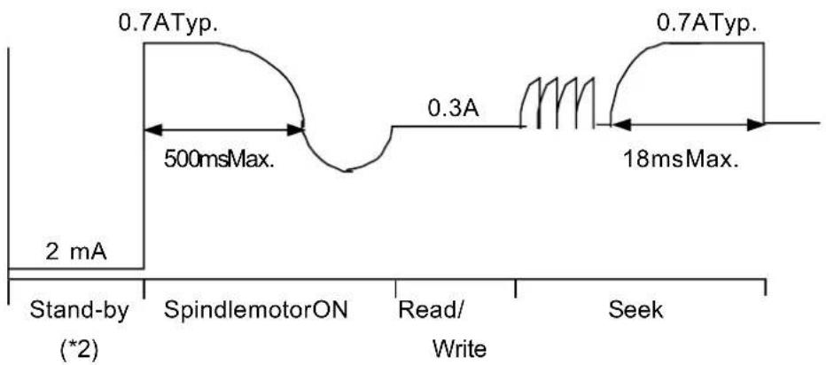
line
| Time Segment | Current (A) | | ------------------ | ----------- | | Stand-by (*2) | 2 mA | | SpindlemotorON | 0.7 ATyp. | | Read/Write | 0.3 A | | Seek | 0.7 ATyp. |(*1) Typical values are specified at 5.0V
(*2) Stand-by: Under the condition that all input lines are inactive.
| FLOPPY DISK DRIVE SPECIFICATION | PAGE9 | |
| MODEL | SFD-321B |
2.5 Physical Specifications
| ITEM SPECIFICATION | ||
| Mechanical Dimension | Width(mm)101.6 | |
| Height(mm)25.4 | ||
| Depth(mm)145.0(withoutFrontBezel) | ||
| Weight(gr)460.0typ. | ||
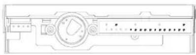
| External View | Refer to Fig. 2-1 and Fig. 2-2 | |
| Installation Holes | Refer to Fig. 2-1 and Fig. 2-2 | |
| HEIGHT | 25.4 MM |
| WIDTH | 1016 MM |
| DEPTH | 145.0 MM |
natural_image
Technical line drawing of a mechanical component with no visible text or symbols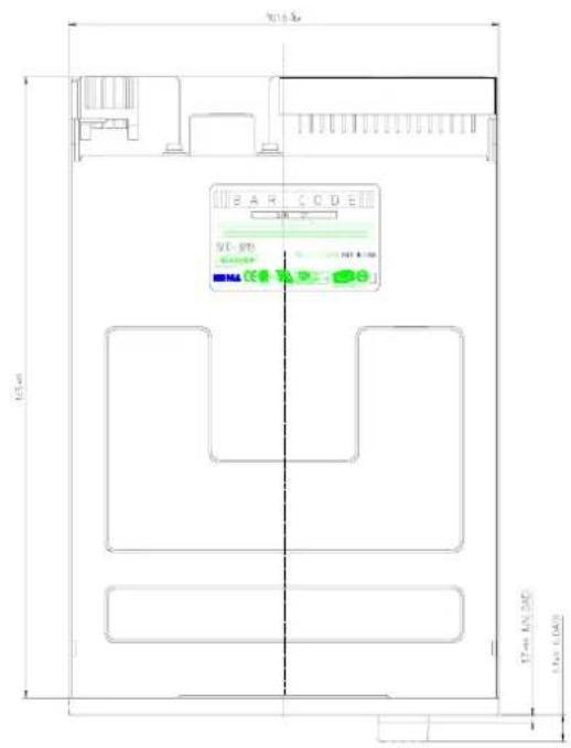
text_image
BAR CODE SCL-SPB MMA CE 17mm LKN 200 15mm LKN 1000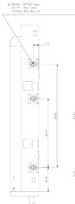
text_image
G-H0×05 TAPPED HOLE -20mm x Max 50mm TORALE MAX SHUL 5 mm 30 mm 70 mm 20 mm 5 mm
text_image
70mm 50mm 30mm
text_image
50 40 26.0 78.5Figure 2-1 Physical Dimensions
PHYSICAL DIMENSIONS
W/O Bezei type)
| HEIGHT | 25.4 mm |
| WIDTH | 101.6 mm |
| DEPTH | 143.0 mm |

natural_image
Architectural floor plan showing room layout and ceiling fixtures (no text or labels)
text_image
75.40 96.40
text_image
OCCR 1.4 3.6 25.0 mm LED 25.0 mm 25.0 mm ELECT BUTTONFigure 2-2 Physics Dimensions
3. INSTALLATION
Installation Direction

natural_image
Pure electrical circuit lines without any symbolsVertical

natural_image
Pure electrical circuit lines without any symbols
natural_image
Pure architectural floor plan lines without any text, numbers, or symbolsHorizontal

natural_image
Technical line drawing of a mechanical component with angular dimension标注 (no text or symbols)* The other installation directions than the aboves will be considered separately.
Figure 3-1 Installation
SEMA ELECTRONICS CO.,LTD
| FLOPPY DISK DRIVE SPECIFICATION | PAGE13 | |
| MODEL | SFD-321B |
4. ELECTRICAL INTERFACE
4.1 Signal Interface
flowchart
graph LR
    A["HOST CONTROLLER SYSTEM"] --> B["DensitySelect"]
    A --> C["InUse(Spare)"]
    A --> D["DriveSelect3(Spare)"]
    A --> E["Index"]
    A --> F["DriveSelect0"]
    A --> G["DriveSelect1"]
    A --> H["DriveSelect2(Spare)"]
    A --> I["MotorOn"]
    A --> J["DirectionSelect"]
    A --> K["Step"]
    A --> L["WriteData"]
    A --> M["WriteGate"]
    A --> N["Track00"]
    A --> O["WriteProtect"]
    A --> P["ReadData"]
    A --> Q["SideSelect"]
    A --> R["Ready/DiskChange"]
    B --> S["FDD SFD-321B(*1)"]
    C --> S
    D --> S
    E --> S
    F --> S
    G --> S
    H --> S
    I --> S
    J --> S
    K --> S
    L --> S
    M --> S
    N --> S
    O --> S
    P --> S
    Q --> S
    R --> S
(*1)Alloddnumbers:GND
4.2 Power Interface
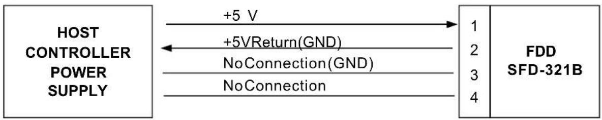
flowchart
graph LR
    A["HOST CONTROLLER POWER SUPPLY"] -->|+5 V| B["FDD SFD-321B"]
    A <-->|+5VReturn(GND)| B
    A <-->|No Connection(GND)| B
    A <-->|No Connection| B
    B -->|1| A
    B -->|2| A
    B -->|3| A
    B -->|4| A
FLOPPY DISK DRIVE SPECIFICATION
PAGE14
MODEL
SFD-321B
4.3 Interface Connectors
4.3.1 Signal Interface Connector
| Side | Connector |
| FDD | HIROSE P/N 5003-001-7347 or equivalent (*1) |
| HOST(Connector) | 3MNO.7934orequivalent |
| HOST(Cable) | 3M3365/34orequivalent(*2) |
(*1)33pins,2.54pitch(Pin#3,5,7,9,13,15,17,19,23,25,27,31:cutoff)
WallType
(*2) Cable length: 1m (3.3 feet) Max.

text_image
2 4 ~ 34 PCB 1 3 ~ 33 PINNO.3,5,7,9,13,15,17,19,23,25,27,31 :Cutoff RearView
text_image
FRONT TopView
natural_image
Simple line drawing of a printer with a paper roll and cable (no text or symbols)Fig 4-1. Signal Interface Connector and Cable Side Connector
| FLOPPY DISK DRIVE SPECIFICATION | PAGE15 | |
| MODEL | SFD-321B |
4.3.2 Power Interface Connector
| Side Connector | |
| FDDELCOP/N | 9251-004-000-809orequivalent |
| HOST(Connector)AMP | 171822-4orequivalent |
| HOST(Cable) | AWG #20-26 |
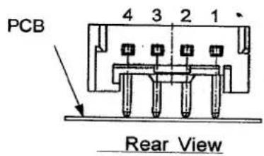
text_image
PCB 4 3 2 1 Rear View
text_image
14.6 m/s 7.8 m/s Top View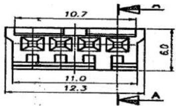
text_image
10.7 6.0 11.0 12.3 AFig 4-2. Power Interface Connector and Cable Side Connector
FLOPPY DISK DRIVE SPECIFICATION
PAGE16
MODEL
SFD-321B
5. SIGNAL CHARACTERISTICS
5.1 Signal Level
| Signal Logic Input Level Output Level (*1) | ||
| Low (True) | 0.9 V Max. | 0.4 V Max. |
| High(False)2.2 | VMin. 2.4 | VMin. |
(*1)"LOW"levelMax.sinkcurrentis48mA.
5.2 Recommended Interface Circuit

text_image
HOST SIDE FDD SIDE 7438SERIES CMOSOR EQUIVALENT (1 kΩ) Vdd CMOS (SCHMITTTRIGGERINPUT) INPUT Vdd 150 Ω~2.2 kΩ (1 kΩ isrecommended) OUTPUT 74LS14 74HC14OR EQUIVALENT OPENDRAIN FRAMEGNDFLOPPY DISK DRIVE SPECIFICATION
PAGE17
MODEL
SFD-321B
5.3 Input Signals
5.3.1 Density Select
Thisiganlisusedtodistinguishbetween1.6MBand2MBMode. TheinterfacepinNo.2canbeusedasDensitySelectInputsignalby attaching0 Ω resistoronto"OPA"shortplugwhentheHighdensitymedia isinserted. The"HIGH"leveldesignates2MBModeandthe"LOW"level designates1.6MBMode.FDDcantellwhethertheinsertedmediaishigh or Low density by checking the signal coming from mechanical switch which detects the densityselectingholeonthemedia.
| Type | Contents |
| 2 Mode(2.0/1.0MB)(Non-connectionof"OPA") | AutomaticSwitching2.0MB:IfHighdensitymediaisinserted.1.0MB:IfLow densitymediaisinserted. |
| 3 Mode(2.0/1.6/1.0MB)(Connectionof"OPA") | AutomaticSwitchingwith"DensitySelect"2.0MB:IfHighdensitymediaisinserted with "DensitySelect"is"HIGH".1.6MB:IfHighdensitymediaisinserted with "Density Select" is "LOW".1.0MB:IfLow densitymediaisinserted "DensitySelect"isnotavailable. |
5.3.2 Drive Select 0 and 1
Twotraceplugs onthePCB,DS0andDS1areprovidedtoselectwhich Drive Select line will activate the interface signals for a unique drive in the daisy chain connection up to two drive units. Drive Select, when activated logical"LOW",enablesalltheI/OlinesexceptMotorOnline. This signal also controls the lightening of In-Use LED.
| FLOPPY DISK DRIVE SPECIFICATION | PAGE18 | |
| MODEL | SFD-321B |
5.3.3 Motor On
Logical"LOW"levelofthissignalmakes the spindle motorbe turned on. Themotorreaches to therated rotational speed within 500 ms after this signalchangesto"LOW". This input signal is ignored when nodisk is installed.
5.3.4 Direction Select
This signals specifies the moving direction of the R/Whead when the Step input is activated. Logical "LOW" level: the direction to the inner track of a disk. "HIGH" level: the direction to the outer track of a disk.
5.3.5 Step
This is a control sign altomov the R/Whead, and the head starts moving at the rising edge of the Step signal.
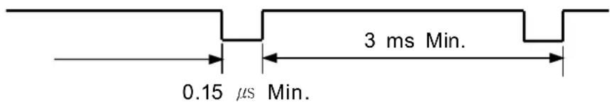
text_image
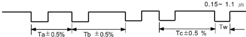
3 ms Min. 0.15 µs Min.5.3.6 Write Data(MFM)
Each time this signal changes from "HIGH" level to "LOW" level, the direction of the current flowing into the R/W head is reversed, and the databitis written on the disk.
other
| Time Segment | Value | | ------------ | ------------ | | Ta ± 0.5% | Ta ± 0.5% | | Tb ± 0.5% | Tb ± 0.5% | | Tc ± 0.5% | Tc ± 0.5% | | Tw | Tw | | 0.15 - 1.1 | 1.1 μs || Density Mode | Ta ( s )(Typ.) | Tb ( s )(Typ.) | Tc ( s )(Typ.) | |
| Density | Transfer Rate | |||
| 1.0MB | 250 kbps | 4 | 6 | 8 |
| 1.6MB | 500 kbps | 2 | 3 | 4 |
| 2.0MB | 500 kbps | 2 | 3 | 4 |
FLOPPY DISK DRIVE SPECIFICATION
PAGE19
MODEL
SFD-321B
5.3.7 Write Gate
"LOW"levelofthissignalenablesthewritedatatobewrittenonthedisk provided thatthedriveisselected,diskusedisnotwriteprotectedand seekoperationiscompleted.
When this signal changesto "HIGH" level, thereador seek operation becomes possible.
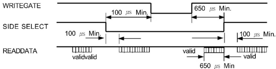
5.3.8 Side Select
This signalselectsthesideofHeads.
Logical"HIGH"level:thelowerside(side0)ofHeads
"LOW"level: theupperside(side1) of Heads
text_image
WRITEGATE SIDE SELECT 100 µs Min. 650 µs Min. 100 µs Min. 100 µs Min. READDATA validvalid valid valid 650 µs Min5.4 Output Signals
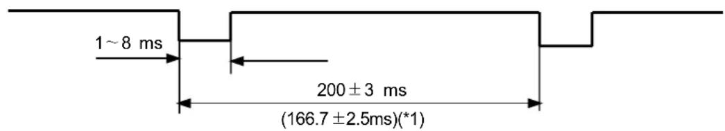
5.4.1 Index
Thisisapulsesignaloutputtoindicatethestartofthetrack, andit outputsateveryrevolutionofthedisk.
This output signal is activated when only the drive is in Readystate.
text_image
1~8 ms 200 ± 3 ms (166.7 ± 2.5ms)(*1)(*1) The value in parenthesis is for 360 rpm (1.6MB Mode) rotation speed.
FLOPPY DISK DRIVE SPECIFICATION
PAGE20
MODEL
SFD-321B
5.4.2 Track 00
"LOW" level of this signal indicates the head is on Track 00 position and stepping motoris at the specified position respectively.
5.4.3 Write Protect
When a write-protected disk is inserted, this signal becomes "LOW" and the data on the disk is protected from mis-erasing and the write operation is inhibited.
5.4.4 Read Data (MFM)
ReadDatareadoutfromthediskistransferredtothehostsystem inthesameformasitwasreceivedontheWriteDataline.Eachflux reversalsensedonthediskproducetheonlytransitionfrom"HIGH" level to "LOW" level. For the seperation of the clock bits from the data, the leading edge of a change from "HIGH" to "LOW" level is used.

text_image
Ta±0.5 % Tb±0.5% Tc±0.5% 400ns ±20 %| Density Mode | Ta (μs) (Typ.) | Tb (μs) (Typ.) | Tc (μs) (Typ.) | |
| Density | Transfer Rate | |||
| 1.0MB | 250 kbps | 4 | 6 | 8 |
| 1.6MB | 500 kbps | 2 | 3 | 4 |
| 2.0MB | 500 kbps | 2 | 3 | 4 |
| FLOPPY DISK DRIVE SPECIFICATION | PAGE21 | |
| MODEL | SFD-321B |
5.4.5 Disk Change / Ready
By selecting proper trace plugs, this signal line (pin #34) can be used for ReadyorDiskChangeline.
-.Ready
This line becomes active "LOW" when the drive is selected, a disk is clamped and the spindle motor is up to speed.
(aftercountingatleasttwoIndexpulses)
Otherwisethislinegoeslogical"HIGH"level.
-.DiskChange
This line is active "LOW" unless disk is clamped and a Steppulse is received when the drive is selected.

other
| Signal | Value | |------------|-----------| | DRIVESELECT | Inserted | | DISKIN | ejected | | STEP | - | | DISK | - | | CHANGE | 0.5 µs Max | | 0.5 µs Max | 0.5 µs Max || FLOPPY DISK DRIVE SPECIFICATION | PAGE22 | |
| MODEL | SFD-321B |
6. TIMING DIAGRAM
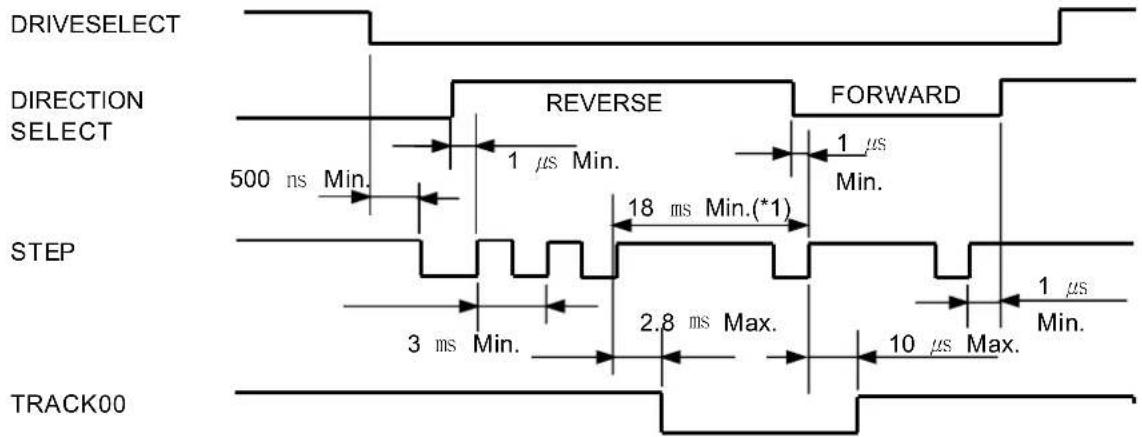
6.1 Seek Operation Timing
text_image
DRIVESELECT DIRECTION SELECT 500 ns Min. REVERSE 1 µs Min. 1 µs FORWARD 1 µs Min. STEP 3 ms Min. 2.8 ms Max. 10 µs Max. 1 µs Min. TRACK006.2 Read / Write Operation Timing

other
| Operation | Duration (μs) | | --------------- | ------------- | | MOTORON | 650 | | DRIVESELECT | 600 | | READY | 0.3 | | STEP | (*2) | | DENSITY SELECT | 18msMin. | | READDATA | 0 Min. | | WRITEGATE | 18msMin. | | WRITEDATA | 0 Min. |(*1) Turn Around Time is 18ms Min. when Direction is changed.
(*2)750 μs Min.(including100 μs SideSelecttiming)
(*3) Whenspindle motorspeed is changed (300rpm 360rpm) this value is 500 ms Min.
| FLOPPY DISK DRIVE SPECIFICATION | PAGE23 | |
| MODEL | SFD-321B | |
| 7. SAFETY STANDARDSThisdriveisapprovedbythefollowings;CECSAULTUVMIC.BSMI.FCC | ||
FLOPPY DISK DRIVE SPECIFICATION
PAGE24
MODEL
SFD-321B
8. PACKAGING DESCRIPTION
8.1 Label Description
8.1.1 Serial Number Label Marking
| FBT6 BAR CODES1ARB00001 | F | B | T | 6 | S | 1 | A | L | B | 0 | 0 | |
| 1 | 2 | 3 | 4 | 5 | 6 | 7 | 8 | 9 | ||||
① Productname : "F" → FDD
② Model name : "B" → SFD-321B
③ Revisionname(Major)
④ Revisionname(Minor)
⑤ Production division : "S" → SEMAELECTRONICSCO.,LTD
⑥ Productionsite
| Marking | 1 | 2 |
| Productionsite | Chinafactory (SEMAChina) | Outsidesupplier (OEM) |
⑦ Production line: "A" → A-Line, "B"\~"Z"
⑧ Year of manufacturing
| Year | 2001 | 2002 | 2003 | 2004 | 2005 | 2006 | 2007 |
| Marking | M | N | P | Q | R | S | T |
⑨ Month of manufacturing
| Month | Marking | Month | Marking | Month | Marking | Month | Marking |
| 1 | 1 | 4 | 4 | 7 | 7 | 10 | A |
| 2 | 2 | 5 | 5 | 8 | 8 | 11 | B |
| 3 | 3 | 6 | 6 | 9 | 9 | 12 | C |
⑩ Consecutive number
8.1.2 Label Description
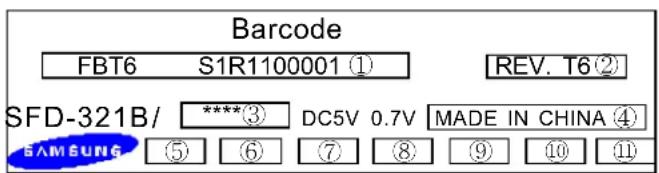
text_image
Barcode FBT6 S1R1100001 ① REV. T6② SFD-321B/ ****③ DC5V 0.7V MADE IN CHINA ④ SAMSUNG ⑤ ⑥ ⑦ ⑧ ⑨ ⑩ ⑪① Serial number
② Revision
③ Buyername
④ Productionsite
⑤ CEmarking
⑥ CSAmarking
⑦ UL marking
⑧ TUVmarking
⑨ MICmarking(foronlydomestic)
⑩ BSMImarking
⑪ Labelmanufactureridentification
Packaging Method
| PROFESSION |  |  | 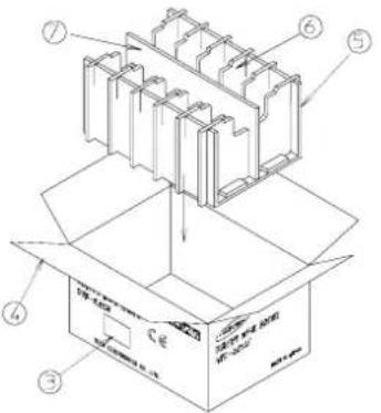 | 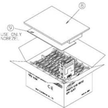 |
| METHOD | 1 | 2 | 3 | 4 |
| PROCESSORS |  |  |  | |
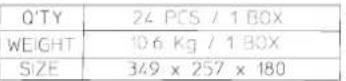 | NOTE)1 Q'TY --> per 1 BOX2 SIZE --> Inside dimension | |||
| METHOD | 5 | 6 | ||
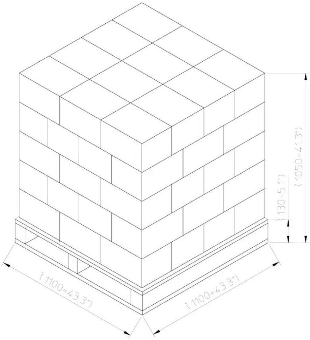
text_image
(130=5.1") (1050=41.3") (1100=43.3") (1100=43.3")| Q'TY | 1440pcs/pallet (12 carton/5layer) | |
| WEIGHT | 653 kg/pallet (APPROX) | |
| PALLET SIZE | (1100) × (1100) × (130) | |
| 1 PALLET SIZE | (1100) × (1100) × (1050) | |
| TOTAL Q'TY | 20ft CONTAINER(2330×5885×2240) | 28,800 pcs |
| 40ft CONTAINER(2330×11930×2240) | 57,600 pcs | |
| FLOPPY DISK DRIVE SPECIFICATION | PAGE27 | |
| MODEL | SFD-321B |
9. OPTION SELECTION
FDD can be modified for different functions than the standards specification. These modifications should be implemented by the factory according to the request of the customers.
9.1 Trace Options
By putting a chip-resistor onto a proper trace, FDD can be used for the following different functions.
| Trace Name Description | |
| DS0 | ActivateDriveSelect0line |
| DS1 | ActivateDriveSelect1line |
| DC | ActivateDiskChangeSignal |
| RDY | ActivateReadySignal |
| OPA | For3Modeusage |
| OPB(*1) | For1.6MBusage |
(*1) Both "OPA" and "OPB" open : 2 Mode (1MB / 2MB)
"OPB" is connected and "OPA" is open : 2 Mode (1MB / 1.6MB)
"OPA" is connected and "OPB" is open : 3 Mode (1MB / 1.6MB / 2MB)
| FLOPPY DISK DRIVE SPECIFICATION | PAGE28 | |
| MODEL | SFD-321B |
9.2 Other Options (Buyer Selection)
The color of In-Use LED, Front-Panel, the value of the termination resistors and the shape of button can be modified by customers' request.
9.2.1 Mode
| ☐ | 2 Mode (1 MB / 2 MB) |
| ☐ | 3Mode(1MB/1.6MB/2MB) |
9.2.2 The Selection of Bezel Type
| □ | WithBezel |
| □ | WithoutBezel |
9.2.3 The Color of Bezel, Button
| □ | Black | |
| □ | Ivory | |
| □ | Gray | |
| Color Number | ____ (Fill in this blank) | |
9.2.4 The Selection of LED Color
| □ | Green |
| □ | Red |
| □ | Amber |
| FLOPPY DISK DRIVE SPECIFICATION | PAGE29 | |
| MODEL | SFD-321B | |
| 11. GENERAL COMMENT | ||