WR250F (2010) - Motorcycle YAMAHA - Free user manual and instructions
Find the device manual for free WR250F (2010) YAMAHA in PDF.

User questions about WR250F (2010) YAMAHA
0 question about this device. Answer the ones you know or ask your own.
Ask a new question about this device
Download the instructions for your Motorcycle in PDF format for free! Find your manual WR250F (2010) - YAMAHA and take your electronic device back in hand. On this page are published all the documents necessary for the use of your device. WR250F (2010) by YAMAHA.
USER MANUAL WR250F (2010) YAMAHA
OWNER'S SERVICE MANUAL
MANUEL D'ATELIER DU
PROPRIETAIRE
FAHRER- UND
WARTUNGSHANDBUCH
Read this manual carefully before operating this vehicle.
OWNER'S SERVICE MANUAL
WVR25
W
100-57-
5UM-
WR250F (Z)
OWNER'S SERVICE MANUAL
©2009 by Yamaha Motor Co., Ltd.
1st Edition, July 2009
All rights reserved. Any reprinting or
unauthorized use without the written
permission of Yamaha Motor Co., Ltd.
is expressly prohibited.
Printed in Japan
FOREWORD
INTRODUCTION
Congratulations on your purchase of a Yamaha WR series. This model is the culmination of Yamaha's vast experience in the production of pacesetting racing machines. It represents the highest grade of craftsmanship and reliability that have made Yamaha a leader.
This manual explains operation, inspection, basic maintenance and tuning of your machine. If you have any questions about this manual or your machine, please contact your Yamaha dealer.
For Canada
The design and manufacture of this Yamaha machine fully comply with the emissions standards for clean air applicable at the date of manufacture. Yamaha has met these standards without reducing the performance or economy of operation of the machine. To maintain these high standards, it is important that you and your Yamaha dealer pay close attention to the recommended maintenance schedules and operating instructions contained within this manual.
TIP
Yamaha continually seeks advancements in product design and quality. Therefore, while this manual contains the most current product information available at the time of printing, there may be minor discrepancies between your machine and this manual. If you have any questions concerning this manual, please consult your Yamaha dealer.
WARNING
PLEASE READ THIS MANUAL CAREFULLY AND COMPLETELY BEFORE OPERATING THIS MACHINE. DO NOT ATTEMPT TO OPERATE THIS MACHINE UNTIL YOU HAVE ATTAINED A SATISFACTORY KNOWLEDGE OF ITS CONTROLS AND OPERATING FEATURES AND UNTIL YOU HAVE BEEN TRAINED IN SAFE AND PROPER RIDING TECHNIQUES. REGULAR INSPECTIONS AND CAREFUL MAINTENANCE, ALONG WITH GOOD RIDING SKILLS, WILL ENSURE THAT YOU SAFETY ENJOY THE CAPABILITIES AND THE RELIABILITY OF THIS MACHINE.
IMPORTANT MANUAL INFORMATION
Particularly important information is distinguished in this manual by the following notations.
!
This is the safety alert symbol. It is used to alert you to potential personal injury hazards. Obey all safety messages that follow this symbol to avoid possible injury or death.
WARNING
A WARNING indicates a hazardous situation which, if not avoided, could result in death or serious injury.
NOTICE
A NOTICE indicates special precautions that must be taken to avoid damage to the vehicle or other property.
TIP
A TIP provides key information to make procedures easier or clearer.
SAFETY INFORMATION
For Canada
This machine is designed for off-road use only. It is illegal for this machine to be operated on any public street, road, or highway. Off-road use on public lands may be illegal. Please check local regulations before riding.
Except for Canada
THIS MACHINE IS DESIGNED STRICTLY FOR COMPETITION USE, ONLY ON A CLOSED COURSE. It is illegal for this machine to be operated on any public street, road, or highway. Off-road use on public lands may also be illegal. Please check local regulations before riding.
- THIS MACHINE IS TO BE OPERATED BY AN EXPERIENCED RIDER ONLY. Do not attempt to operate this machine at maximum power until you are totally familiar with its characteristics.
- THIS MACHINE IS DESIGNED TO BE RIDDEN BY THE OPERATOR ONLY.
Do not carry passengers on this machine.
• ALWAYS WEAR PROTECTIVE APPAREL.
When operating this machine, always wear an approved helmet with goggles or a face shield. Also wear heavy boots, gloves, and protective clothing. Always wear proper fitting clothing that will not be caught in any of the moving parts or controls of the machine.
• ALWAYS MAINTAIN YOUR MACHINE IN PROPER WORKING ORDER.
For safety and reliability, the machine must be properly maintained. Always perform the pre-operation checks indicated in this manual. Correcting a mechanical problem before you ride may prevent an accident.
• GASOLINE IS HIGHLY FLAMMA-BLE.
Always turn off the engine while refueling. Take care to not spill any gasoline on the engine or exhaust system. Never refuel in the vicinity of an open flame, or while smoking.
• GASOLINE CAN CAUSE INJURY. If you should swallow some gasoline, inhale excess gasoline vapors, or allow any gasoline to get into your eyes, contact a doctor immediately. If any gasoline spills onto your skin or clothing, immediately wash skin areas with soap and water, and change your clothes.
- ONLY OPERATE THE MACHINE IN AN AREA WITH ADEQUATE VENTILATION.
Never start the engine or let it run for any length of time in an enclosed area. Exhaust fumes are poisonous. These fumes contain carbon monoxide, which by itself is odorless and colorless. Carbon monoxide is a dangerous gas which can cause unconsciousness or can be lethal.
- PARK THE MACHINE CAREFULLY; TURN OFF THE ENGINE. Always turn off the engine if you are going to leave the machine. Do not park the machine on a slope or soft ground as it may fall over.
• THE ENGINE, EXHAUST PIPE, MUFFLER, AND OIL TANK WILL BE VERY HOT AFTER THE ENGINE HAS BEEN RUN.
Be careful not to touch them or to allow any clothing item to contact them during inspection or repair.
• PROPERLY SECURE THE MACHINE BEFORE TRANSPORTING IT.
When transporting the machine in another vehicle, always be sure it is properly secured and in an upright position and that the fuel cock is in the "OFF" position. Otherwise, fuel may leak out of the carburetor or fuel tank.
F.I.M. MACHINE WEIGHTS (Except for Canada)
Weights of machines without fuel
The minimum weights for motocross machines are:
for the class 125 cc:
minimum 88 kg (194 lb)
for the class 250 cc:
minimum 98 kg (216 lb)
for the class 500 cc:
minimum 102 kg (225 lb)
In modifying your machine (e.g., for weight reduction), take note of the above limits of weight.
HOW TO USE THIS MANUAL
FINDING THE REQUIRED PAGE
-
This manual consists of seven chapters; "General Information", "Specifications", "Regular inspection and adjustments", "Tuning", "Engine", "Chassis" and "Electrical".
-
The table of contents is at the beginning of the manual. Look over the general layout of the book before finding then required chapter and item.
Bend the book at its edge, as shown, to find the required fore edge symbol mark and go to a page for required item and description.

natural_image
Illustration of two hands holding an open notebook with visible page number lines (no text or symbols on pages)MANUAL FORMAT
All of the procedures in this manual are organized in a sequential, step-by-step format. The information has been complied to provide the mechanic with an easy to read, handy reference that contains comprehensive explanations of all disassembly, repair, assembly, and inspection operations.
In this revised format, the condition of a faulty component will precede an arrow symbol and the course of action required will follow the symbol, e.g.,
- Bearings Pitting/damage → Replace.
HOW TO READ DESCRIPTIONS
To help identify parts and clarify procedure steps, there are exploded diagrams at the start of each removal and disassembly section.
-
An easy-to-see exploded diagram "1" is provided for removal and disassembly jobs.
-
Numbers "2" are given in the order of the jobs in the exploded diagram. A number that is enclosed by a circle indicates a disassembly step.
-
An explanation of jobs and notes is presented in an easy-to-read way by the use of symbol marks "3". The meanings of the symbol marks are given on the next page.
-
A job instruction chart "4" accompanies the exploded diagram, providing the order of jobs, names of parts, notes in jobs, etc.
-
For jobs requiring more information, the step-by-step format supplements "5" are given in addition to the exploded diagram and job instruction chart.

text_image
Technical diagram and description of clutch parts with labeled parts and technical specificationsILLUSTRATED SYMBOLS (Refer to the illustration)

text_image
1 2 3 4 5 6 7 8 9 10 11 12 13 14 15 NewIllustrated symbols "1" to "7" are used to identify the specifications appearing in the text.
-
With engine mounted
-
Filling fluid
-
Lubricant
-
Special tool
-
Tightening
-
Specified value, Service limit
-
Resistance (Ω), Voltage (V), Electric current (A)
Illustrated symbols "8" to "13" in the exploded diagrams indicate grade of lubricant and location of lubrication point.
-
Apply engine oil
-
Apply molybdenum disulfide oil
-
Apply brake fluid
-
Apply lightweight lithium-soap base grease
-
Apply molybdenum disulfide grease
-
Apply silicone grease
Illustrated symbols "14" to "15" in the exploded diagrams indicate where to apply a locking agent and where to install new parts.
-
Apply locking agent (LOC-TITE®)
-
Use new one
TABLE OF CONTENTS
| GENERAL INFORMATION | 1 |
| SPECIFICATIONS | 2 |
| REGULAR INSPECTION AND ADJUSTMENTS | 3 |
| TUNING | 4 |
| ENGINE | 5 |
| CHASSIS | 6 |
| ELECTRICAL | 7 |
CONTENTS
CHAPTER 1 GENERAL INFOR- MATION
LOCATION OF
IMPORTANT LABELS ..... 1-1
DESCRIPTION .....1-5
CONSUMER
INFORMATION...... 1-6
INCLUDED PARTS .....1-6
IMPORTANT
INFORMATION...... 1-6
CHECKING OF
CONNECTION......1-7
SPECIAL TOOLS...... 1-8
CONTROL FUNCTIONS .. 1-12
MULTI-FUNCTION
DISPLAY 1-13
STARTING AND
BREAK-IN 1-18
TORQUE-CHECK
POINTS.... 1-20
CLEANING AND
STORAGE 1-21
CHAPTER 2 SPECIFICATIONS
GENERAL
SPECIFICATIONS......2-1
MAINTENANCE
SPECIFICATIONS......2-3
TIGHTENING
TORQUES 2-12
LUBRICATION
DIAGRAMS 2-19
CABLE ROUTING
DIAGRAM....2-21
CHAPTER 3 REGULAR INSPEC- TION AND AD- JUSTMENTS
PERIODIC MAINTENANCE CHART FOR THE EMISSION CONTROL SYSTEM (For Canada)....3-1
GENERAL MAINTENANCE AND LUBRICATION CHART (For Canada)....3-2
MAINTENANCE INTER- VALS FOR COMPETITION USE....3-3
PRE-OPERATION
INSPECTION AND
MAINTENANCE....3-7
ENGINE 3-8
CHASSIS ....3-19
ELECTRICAL ....3-29
CHAPTER 4 TUNING
ENGINE
(Except for Canada) .....4-1
CHASSIS 4-5
CHAPTER 5 ENGINE
RADIATOR 5-1
CARBURETOR....5-4
AIR INDICTION
SYSTEM 5-12
CAMSHAFTS......5-14
CYLINDER HEAD......5-19
VALVES AND VALVE
SPRINGS....5-21
CYLINDER AND
PISTON....5-25
CLUTCH 5-29
OIL FILTER ELEMENT
AND WATER PUMP......5-34
BALANCER 5-39
OIL PUMP....5-41
KICK SHAFT AND SHIFT
SHAFT 5-44
AC MAGNETO AND
STARTER CLUTCH.....5-49
ENGINE REMOVAL.....5-54
CRANKCASE AND
CRANKSHAFT .....5-58
TRANSMISSION,
SHIFT CAM AND
SHIFT FORK......5-64
CHAPTER 6 CHASSIS
FRONT WHEEL AND
REAR WHEEL ......6-1
FRONT BRAKE AND
REAR BRAKE 6-6
FRONT FORK......6-16
HANDLEBAR......6-23
STEERING......6-27
SWINGARM......6-31
REAR SHOCK
ABSORBER......6-36
CHAPTER 7 ELECTRICAL
ELECTRICAL COMPO-
NENTS AND WIRING
DIAGRAM 7-1
IGNITION SYSTEM......7-3
ELECTRIC STARTING
SYSTEM....7-5
CHARGING SYSTEM.....7-13
THROTTLE POSITION
SENSOR SYSTEM .....7-15
LIGHTING SYSTEM .....7-18
SIGNALING SYSTEM.....7-20
GENERAL INFORMATION
LOCATION OF IMPORTANT LABELS
Please read the following important labels carefully before operating this vehicle.

text_image
①②③ ④⑤⑥⑦ ⑧⑨ ⑩⑪⑫⑬⑭⑮ ⑰⑱⑲⑳⑴⑵CANADA
1
Premium unleaded gasoline only.
3FB-2415E-02
2
This spark ignition system meets all requirements of the Canadian Interference Causing Equipment Regulations.
This unit contains high pressure nitrogen gas. Mishandling can cause explosion.
- Read owner's manual for instructions.
- Do not incinerate, puncture or open.

AVERTISSEMENT
● BEFORE YOU OPERATE THIS VEHICLE, READ THE OWNER'S MANUAL AND ALL LABELS.
- NEVER CARRY A PASSENGER. You increase your risk of losing control if you carry a passeng
- NEVER OPERATE THIS VEHICLE ON PUBLIC ROADS. You can collide with another vehicle if you operate this vehicle on a public road.
● ALWAYS WEAR AN APPROVED MOTORCYCLE HELMET, eye protection, and protective clothing.
● EXPERIENCED RIDER ONLY.
5PA-2118K-00
11
AVERTISSEMENT
text_image
4AA-22259-4012
WARNING
Riding as a passenger can cause the vehicle to go out of control.
Loss of control can cause a collision or rollover, which can result in severe injury or death.
NEVER ride as a passenger.
3XJ-2151H-A1
13
AVERTISSEMENT
Cold tire normal pressure should be set as
follows.
text_image
4AA-22259-4016
TIRE INFORMATION
Cold tire normal pressure should be set as
follows.
Familiarize yourself with the following pictograms and read the explanatory text.


Read Owner's service manual.
This unit contains high-pressure nitrogen gas. Mishandling can cause explosion. Do not incinerate, puncture or open.
Turn off the main switch after riding to avoid draining the battery.
Use unleaded gasoline only.
Measure tire pressure when tires are cold.
Adjust tire pressure.
Improper tire pressure can cause loss of control.
Loss of control can result in severe injury or death.
DESCRIPTION

text_image
Technical diagram of a mechanical assembly with numbered components for identification
text_image
Technical diagram of a motorcycle with numbered parts for identification
text_image
Technical diagram of a motorcycle with numbered parts for identification- Clutch lever
- Hot starter lever
- Engine stop switch
- Multi-function display
- Main switch
- Start switch
- Front brake lever
- Throttle grip
- Radiator cap
- Fuel tank cap
- Taillight
- Kickstarter crank
-
Fuel tank
-
Headlight
- Radiator
- Coolant drain bolt
- Rear brake pedal
- Valve joint
- Fuel cock
- Cold starter knob
- Air cleaner
- Catch tank
- Drive chain
- Oil level check window
- Shift pedal
- Front fork
TIP
• The machine you have purchased may differ slightly from those shown in the following.
- Designs and specifications are subject to change without notice.
CONSUMER INFORMATION
There are two significant reasons for knowing the serial number of your machine:
- When ordering parts, you can give the number to your Yamaha dealer for positive identification of the model you own.
- If your machine is stolen, the authorities will need the number to search for and identify your machine.
VEHICLE IDENTIFICATION NUMBER
The vehicle identification number "1" is stamped on the right of the steering head pipe.

natural_image
Technical line drawing of a mechanical assembly with no visible text or symbolsENGINE SERIAL NUMBER
The engine serial number "1" is stamped into the elevated part of the right-side of the engine.

natural_image
Technical line drawing of a mechanical assembly with no visible text or symbolsMODEL LABEL
The model label "1" is affixed to the frame under the rider's seat. This information will be needed to order spare parts.

natural_image
Technical line drawing of a vehicle interior showing engine compartment and structural components (no text or labels)VEHICLE EMISSION CONTROL INFORMATION LABEL (For Canada)
The Vehicle Emission Control Information label "1" is affixed at the location in the illustration. This label shows specifications related to exhaust emissions as required by federal law, state law and Environment Canada.
A

B

A. Left
B. Right
INCLUDED PARTS
VALVE JOINT
This valve joint "1" prevents fuel from flowing out and is installed to the fuel tank breather hose.
NOTICE
In this installation, make sure the arrow faces the fuel tank and also downward.

text_image
Technical diagram of a robotic arm with labeled component and inset view showing a watch.SPARK PLUG WRENCH
This spark plug wrench "1" is used to remove and install the spark plug.


natural_image
Technical line drawing of a mechanical assembly with numbered components (no text or symbols)NIPPLE WRENCH
This nipple wrench "1" is used to tighten the spoke.

text_image
Technical diagram showing a hand holding a tool with labeled parts, likely illustrating a mechanical or electrical component.JET NEEDLE PULL-UP TOOL (Except for Canada)
The jet needle pull-up tool "1" is used to pull the jet needle out of the carburetor.

text_image
Technical diagram showing mechanical assembly with labeled parts and a close-up inset of the toolDRIVE CHAIN SPROCKET GUIDE (For EUROPE)
Use the drive chain sprocket guide "1" when installing the included drive sprockt (13T).

natural_image
Technical line drawing of a mechanical assembly with no visible text or symbolsIMPORTANT INFORMATION PREPARATION FOR REMOVAL AND DISASSEMBLY
- Remove all dirt, mud, dust, and foreign material before removal and disassembly.
- When washing the machine with high pressured water, cover the parts follows.
Silencer exhaust port
Side cover air intake port
Water pump housing hole at the bottom
Drain hole on the cylinder head (right side)
All electrical components

natural_image
Cartoon illustration of a person washing a motorcycle with buckets (no text or symbols)


- Use proper tools and cleaning equipment. Refer to "SPECIAL TOOLS" section.

natural_image
Cartoon illustration of a mechanic working on a motorcycle with a tool nearby (no text or symbols)- When disassembling the machine, keep mated parts together. They include gears, cylinders, pistons, and other mated parts that have been "mated" through normal wear. Mated parts must be reused as an assembly or replaced.

natural_image
Illustration of a person handling food items with stacked dishes (no text or symbols)- During the machine disassembly, clean all parts and place them in trays in the order of disassembly. This will speed up assembly time and help assure that all parts are correctly reinstalled.

natural_image
Cartoon illustration of a man sitting on the floor surrounded by money bags and a question mark (no text or symbols)- Keep away from fire.
ALL REPLACEMENT PARTS
- We recommend to use Yamaha genuine parts for all replacements. Use oil and/or grease recommended by Yamaha for assembly and adjustment.
GASKETS, OIL SEALS AND O- RINGS
-
All gaskets, oil seals, and O-rings should be replaced when an engine is overhauled. All gasket surfaces, oil seal lips, and O-rings must be cleaned.
-
Properly oil all mating parts and bearings during reassembly. Apply grease to the oil seal lips.
LOCK WASHERS/PLATES AND COTTER PINS
- All lock washers/plates "1" and cotter pins must be replaced when they are removed. Lock tab(s) should be bent along the bolt or nut flat(s) after the bolt or nut has been properly tightened.

text_image
Technical diagram showing two hexagonal nuts connected to a bolt on a surface, with label '1' indicating part number.BEARINGS AND OIL SEALS
- Install the bearing(s) "1" and oil seal(s) "2" with their manufacturer's marks or numbers facing outward. (In other words, the stamped letters must be on the side exposed to view.) When installing oil seal(s), apply a light coating of lightweight lithium base grease to the seal lip(s). Oil the bearings liberally when installing.
NOTICE
Do not use compressed air to spin the bearings dry. This causes damage to the bearing surfaces.


text_image
Technical diagram of a mechanical assembly with labeled component '2' and directional arrowCIRCLIPS
- All circlips should be inspected carefully before reassembly. Always replace piston pin clips after one use. Replace distorted circlips. When installing a circlip "1", make sure that the sharp-edged corner "2" is positioned opposite to the thrust "3" it receives. See the sectional view.

text_image
1 2 3CHECKING OF CONNECTION
Dealing with stains, rust, moisture, etc. on the connector.
- Disconnect:
- Connector
- Dry each terminal with an air blower.

natural_image
Two hand-drawn diagrams showing a tool being inserted into a cable, no text or symbols present.- Connect and disconnect the connector two or three times.
- Pull the lead to check that it will not come off.
- If the terminal comes off, bend up the pin "1" and reinsert the terminal into the connector.

text_image
Technical diagram showing two-step assembly steps for a mechanical component, with labeled parts and directional arrows.- Connect:
- Connector
TIP
The two connectors "click" together.
- Check for continuity with a tester.
TIP
- If there in no continuity, clean the terminals.
- Be sure to perform the steps 1 to 7 listed above when checking the wire harness.
- For a field remedy, use a contact revitalizer available on the market.
- Use the tester on the connector as shown.

text_image
Diagram showing electrical testing setup with probe, bulb, and multimeter connected to a plug
natural_image
Pure electrical circuit lines without any symbolsSPECIAL TOOLS
The proper special tools are necessary for complete and accurate tune-up and assembly. Using the correct special tool will help prevent damage caused by the use of improper tools or improvised techniques. The shape and part number used for the special tool differ by country, so two types are provided. Refer to the list provided to avoid errors when placing an order.
TIP
- For U.S.A. and Canada, use part number starting with "YM-", "YU-" or "ACC-".
- For others, use part number starting with "90890-".
| Tool name/Part number How to use Illustration | ||
| Crankcase separating toolYU-1135-A, 90890-01135 | These tool is used to remove the crankshaft from either case. |  |
| Dial gauge and standYU-3097, 90890-01252StandYU-1256 | These tools are used to check each part for runout or bent. |   |
| Crankshaft installing toolCrankshaft installing potYU-90050, 90890-01274Crankshaft installing boltYU-90050, 90890-01275Spacer (crankshaft installer)YU-91044, 90890-04081Adapter (M12)YU-90063, 90890-01278 | These tools are used to install the crankshaft. |   |
| Piston pin puller setYU-1304, 90890-01304 | This tool is used to remove the piston pin. |  |
| Radiator cap testerYU-24460-01, 90890-01325Radiator cap tester adapterYU-33984, 90890-01352 | These tools are used for checking the cooling system. |   |
| Steering nut wrenchYU-33975, 90890-01403 | This tool is used when tighten the steering ring nut to specification. |  |
| Damper rod holderYM-01494, 90890-01494 | Use this tool to remove and install the damper rod. |  |
| Fork seal driverYM-A0948, 90890-01502 | This tool is used when install the fork oil seal. |   |
| Spoke nipple wrenchYM-01521, 90890-01521 | This tool is used to tighten the spoke. |  |
| Sheave holderYS-1880-A, 90890-01701 | This tool is used for when loosening or tightening the flywheel magneto securing nut. |   |
| Pocket testerYU-3112-C, 90890-03112 | Use this tool to inspect the coil resistance, output voltage and amper-age. |  |
| Timing lightYM-33277-A, 90890-03141 | This tool is necessary for checking ignition timing. |  |
 | ||
| Valve spring compressorYM-4019, 90890-04019 | This tool is needed to remove and install the valve assemblies. |  |
| Clutch holding toolYM-91042, 90890-04086 | This tool is used to hold the clutch when removing or installing the clutch boss securing nut. |  |
 | ||
| Valve guide removerIntake 4.0 mm (0.16 in)Exhaust 4.5 mm (0.18 in)YM-4111, 90890-04111YM-4116, 90890-04116 | This tool is needed to remove and install the valve guide. |  |
| Valve guide installerIntake 4.0 mm (0.16 in)Exhaust 4.5 mm (0.18 in)YM-4112, 90890-04112YM-4117, 90890-04117 | This tool is needed to install the valve guide. |  |
| Valve guide reamerIntake 4.0 mm (0.16 in)Exhaust 4.5 mm (0.18 in)YM-4113, 90890-04113YM-4118, 90890-04118 | This tool is needed to rebore the new valve guide. |  |
| Rotor pullerYM-04141, 90890-04141 | This tool is used to remove the fly-wheel magneto. |  |
| Dynamic spark testerYM-34487Ignition checker90890-06754 | This instrument is necessary for checking the ignition system components. |   |
| Vacuum/pressure pump gauge set YB-35956-A, 90890-06756 | This tool is used to check the air induction system. |  |
| YAMAHA Bond No. 1215 (Three-Bond® No. 1215)90890-85505 | This sealant (Bond) is used for crankcase mating surface, etc. |  |
CONTROL FUNCTIONS
MAIN SWITCH
Functions of the respective switch positions are as follows:
ON:
The engine can be started only at this position.
OFF:
All electrical circuits are switched off.
Main switch indicator light
The main switch "1" is equipped with an indicator light "2" to avoid forgetting to turn it off. This light functions as follows.
- It lights up with the main switch "ON".
- It goes out when the engine increases its speed after being started.
- It lights up again when the engine is stopped.
TIP
If the indicator light will not light up with the main switch "ON", it shows a lack of the battery voltage. Recharge the battery.

text_image
Diagram of a car air conditioner unit with labeled controls and indicator lightsENGINE STOP SWITCH
The engine stop switch "1" is located on the left handlebar. Continue pushing the engine stop switch till the engine comes to a stop.

natural_image
Technical line drawing of a mechanical device with labeled parts (no text or symbols present)START SWITCH
The start switch "1" is located on the right handlebar. Push this switch to crank the engine with the starter.

natural_image
Technical line drawing of a mechanical assembly with hoses and components (no text or symbols)CLUTCH LEVER
The clutch lever "1" is located on the left handlebar; it disengages or engages the clutch. Pull the clutch lever to the handlebar to disengage the clutch, and release the lever to engage the clutch. The lever should be pulled rapidly and released slowly for smooth starts.

natural_image
Technical line drawing of a mechanical device with no visible text or symbolsSHIFT PEDAL
The gear ratios of the constant-mesh 5 speed transmission are ideally spaced. The gears can be shifted by using the shift pedal "1" on the left side of the engine.

text_image
5 4 3 2 N 1KICKSTARTER CRANK
Rotate the kickstarter crank "1" away from the engine. Push the starter down lightly with your foot until the gears engage, then kick smoothly and forcefully to start the engine. This model has a primary kickstarter crank so the engine can be started in any gear if the clutch is disengaged. In normal practices, however, shift to neutral before starting.

text_image
Technical diagram of a mechanical assembly with labeled component ①THROTTLE GRIP
The throttle grip "1" is located on the right handlebar; it accelerates or decelerates the engine. For acceleration, turn the grip toward you; for deceleration, turn it away from you.

natural_image
Diagram of a mechanical component with a curved arrow indicating rotation (no text or symbols present)FRONT BRAKE LEVER
The front brake lever "1" is located on the right handlebar. Pull it toward the handlebar to activate the front brake.

natural_image
Technical line drawing of a mechanical component with a handle and base, no visible text or symbolsREAR BRAKE PEDAL
The rear brake pedal "1" is located on the right side of the machine. Press down on the brake pedal to activate the rear brake.

text_image
YAKARAFUEL COCK
The fuel cock supplies fuel from the tank to carburetor and also filters the fuel. The fuel cock has the three positions:
OFF:
With the lever in this position, fuel will not flow. Always return the lever to this position when the engine is not running.
ON:
With the lever in this position, fuel flows to the carburetor. Normal riding is done with the lever in this position. RES:
With the lever in this position fuel flows to the carburetor from the reserve section of the fuel tank after the main supply of the fuel has been depleted. Normal riding is possible with the lever is in this position, but it is recommended to add fuel as soon as possible.

text_image
RES RES OFF ON FUEL ONCOLD STARTER KNOB
When cold, the engine requires a richer air-fuel mixture for starting. A separate starter circuit, which is controlled by the cold starter knob "1", supplies this mixture. Pull the cold starter knob out to open the circuit for starting. When the engine has warmed up, push it in to close the circuit.

natural_image
Line drawing of a car interior showing engine compartment and wheel assembly (no text or symbols)HOT STARTER LEVER
The hot starter lever "1" is used when starting a warm engine. Use the hot starter lever when starting the engine again immediately after it was stopped (the engine is still warm). Pulling the hot starter lever injects secondary air to thin the air-fuel mixture temporarily, allowing the engine to be started more easily.

natural_image
Technical line drawing of a mechanical device with labeled component (no text or symbols present)SIDESTAND
This sidestand "1" is used to support only the machine when standing or transporting it.
WARNING
- Never apply additional force to the sidestand.
- Hold up the sidestand before starting out.

natural_image
Mechanical assembly diagram showing a lever and shaft assembly (no text or labels)MULTI-FUNCTION DISPLAY
WARNING
Be sure to stop the machine before making any setting changes to the multi-function display.
The multi-function display is equipped with the following: BASIC MODE:
- Speedometer
- Clock
- Two tripmeters (which shows the distance that has been traveled since it was last set to zero)
- Timer (which shows the time that has been accumulated since the start of timer measurement)
- Tripmeter (which shows the accumulated travel distance in timer measurement)
- Change tripmeter digits (capable of change to any given ones)
RACE MODE:
DESCRIPTION
Operation buttons:
- Select button "SLCT 1"
- Select button "SLCT 2"
- Reset button "RST"
Screen display:
- Tripmeter indicator
- Tripmeter indicator
- Timer indicator
- Clock/Timer
- Speedometer
- Odometer/Tripmeter
TIP
The operation buttons can be pushed in the following two manners:
Short push: Push the button. (D) Long push: Push the button for 2 seconds or more. (E)

text_image
1 6 7 8 18:88:88 199 8788.8 MPHz 3 2 5 4 9BASIC MODE
Changing speedometer display (for U.K.)
- Push the "SLCT2" button for 2 seconds or more to change the speedometer units. The speedometer display will change in the following order:
MPH → km/h → MPH.

text_image
RST SLCT1 SLCT2 12:00:00 10.0 MPH 12:00:00 16.0 km/hSetting the time
- Push the "SLCT1" button for 2 seconds or more to enter the time setting mode.
- Push the "RST" button to change the display for time indication. The display will change in the following order:
Hour → Minute → Second → Hour.
TIP
The digits capable of setting go on flashing.


flowchart
graph TD
    A["Start"] --> B["SLCT1"]
    A --> C["SLCT2"]
    B --> D["12:00:00"]
    C --> D
    D --> E["12:00:00"]
    E --> F["12:00:00"]
    F --> G["RST"]
    G --> H["Return Signal"]
- Push the "SLCT1" button (plus) or "SLCT2" button (minus) and change the time. A long push on the button will fast-forward the time.

flowchart
graph TD
    A["+"] --> B["SLCT1"]
    C["RST"] --> D["SLCT2"]
    E["-"] --> D
    D --> F["12:00:00"]
    D --> G["10:00:00"]
- To end the setting, push the "RST" button for 2 seconds or more.
TIP
- In a 30-second absence of button operation, the setting will come to an end with the indicated time.
- To reset the seconds, push the "SLCT1" button or "SLCT2" button.
Changing odometer and tripmeter A/B (TRIP A/B)
- Push the "SLCT2" button to change the tripmeter display. The display will change in the following order: Odometer → TRIP A → TRIP B → TRIP A → Odometer.

text_image
RST SLCT1 SLCT2 12:00:00 0 1025 10.0 20.0TIP
To reset the digits, select the tripmeter involved and push the "RST" button for 2 seconds or more.

text_image
RST SLCT1 SLCT2 12:00:00 10.0 0.0CHANGEOVER TO BASIC MODE/RACE MODE
TIP
- Measurement using the timer function can be made in RACE MODE.
- Indicator will light up as an identifier that shows RACE MODE has been selected.
- RACE MODE cannot display the functions as in BASIC MODE.
- Changeover to RACE MODE forces the digits for tripmeter A (TRIP A) in BASIC MODE to be reset.
Changeover from BASIC MODE to RACE MODE
- Push the "SLCT1" button and "SLCT2" button for 2 seconds or more at the same time to change over to RACE MODE.
TIP
Changeover to RACE MODE will put manual start measurement on standby causing F and to A ash. (For manual start, refer to "Putting measurement on standby" in "RACE MODE".)

flowchart
graph TD
    A["RST"] --> B["SLCT1"]
    A --> C["SLCT2"]
    B --> D["12:00:00"]
    C --> E["10.0 MPH"]
    F["RST"] --> G["SLCT1"]
    F --> H["SLCT2"]
    G --> I["0:00:00"]
    H --> J["0.0 MPH"]
    D --> K["0 MPH"]
    I --> L["0 MPH"]
Returning to BASIC MODE from RACE MODE
TIP
It is possible to return to BASIC MODE with timer measurement at a stop.
- Check that the timer is not in operation. If the timer is in operation, stop the timer by pushing the "SLCT1" button and "SLCT2" button at the same time.

text_image
RST SLCT1 SLCT2 0: 15:08 10.3 MPH- Push the "SLCT1" button and "SLCT2" button for 2 seconds or more at the same time to change over to BASIC MODE.

text_image
RST SLCT1 SLCT2 0:00:00 0.0 MPH 12:00:00 0.0 MPHRACE MODE
Putting measurement on standby
TIP
Starting measurement consists of the following two starts, either of which can be selected.
- Manual start
Starting measurement by the rider himself operating the button. (A long push on the "SLCT2" button will put measurement on standby.)
- Auto start
Starting timer measurement automatically on detection of the movement of the machine. (A long push on the "SLCT1" button will put measurement on standby.)
Manual start
TIP
Initial setting at changeover to RACE MODE will remain for manual start.
- Check that changeover to RACE MODE has been made. (Refer to "Changeover from BASIC MODE to RACE MODE".)
TIP
When the machine is made ready for a run by manual start, and with A start flashing.
- Start timer measurement by pushing the "RST" button.

- When stopping timer measurement, pushing the "SLCT1" button and "SLCT2" button at the same time.
TIP
If the machine is run while timer measurement is not made, no change will occur to the digit in tripmeter A (TRIP A).

text_image
RST SLCT1 SLCT2 0: 15:08 10.3 MPH- To resume the measurement, again push the "SLCT1" button and "SLCT2" button at the same time.
Auto start
-
Check that changeover has been made to RACE MODE. (Refer to "Changeover from BASIC MODE to RACE MODE".)
-
Make the machine ready for a run by pushing the "SLCT1" button for 2 seconds or more.
TIP
When the measurement is made ready for a run by auto start, and A will start flashing. Timer display will turn on scrolling from left to right.

flowchart
graph TD
    A["RST"] --> B["SLCT1"]
    A --> C["SLCT2"]
    B --> D["0:00:00"]
    C --> E["0.0"]
    D --> F["MPH"]
    E --> G["0 MPH"]
    H["Output"] --> I["0 MPH"]
- Run the machine and start timer measurement.
- To stop timer measurement, pushing the "SLCT1" button and "SLCT2" button at the same time.
TIP
If the machine is run while timer measurement is not made, no change will occur to the digit in tripmeter A (TRIP A).

text_image
RST SLCT1 SLCT2 0: 15:08 10.3 MPH- To resume the measurement, again pushing the "SLCT1" button and "SLCT2" button at the same time.
Resetting measurement data
TIP
Resetting can be made in the following two manners.
Resetting is possible while timer measurement is made:
- Reset tripmeter A.
Resetting is possible while timer measurement is not made: - Reset tripmeter A and timer.
Resetting tripmeter A (TRIP A)
- Check that the timer is in operation. If the timer is not in operation, start the timer by pushing the "SLCT1" button and "SLCT2" button at the same time.
- Reset tripmeter A (TRIP A) display by pushing the "RST" button for 2 seconds or more.
TIP
If reset, and travel distance display will go on flashing for four seconds.

text_image
RST SLCT1 SLCT2 0:15:08 10.3 0:15:08 -00 0 MPHResetting tripmeter A (TRIP A) and timer
- Check that the timer is not in operation. If the timer is in operation, stop it by pushing the "SLCT1" button and "SLCT2" button at the same time.
- Reset all measured data by pushing the "RST" button for 2 seconds or more.
TIP
- Resetting will reset the timer display and travel distance display and put measurement on standby.
- Auto start attempt will put measurement on standby as such. Likewise, manual start attempt will put measurement on standby as such.

text_image
RST SLCT1 SLCT2 0: 15:08 10.3 MPH 0:00:00 0.0 MPHCorrecting tripmeter A (TRIP A)
- Change the travel distance display by pushing the "SLCT1" button (plus) or "SLCT2" button (minus). A long push on the button will fast-forward the change.
TIP
Change can be made any time while timer measurement is or is not being made.

flowchart
graph TD
    A["+"] --> B["SLC1"]
    B --> C["RST"]
    C --> D["SLC2"]
    D --> E["+"]
    E --> F["0:15-08 50A/40A"]
    F --> G["10.3"]
    G --> H["10.4"]
    H --> I["+"]
    H --> J["10.2"]
    J --> K["-"]
FUNCTION DIAGRAM

flowchart
graph TD
    A["① BASIC MODE"] --> B["② Clock"]
    B --> C["SLCT1"]
    C --> D["SLCT2"]
    D --> E["③ Tripmeter"]
    E --> F["ODO -TRIP A TRIP B → ODO"]
    D --> G["④ Speedometer (for U.K.) MPH → km/h -MPH"]
    G --> H["SLCT1 + SLCT2"]
    H --> I["⑥ Putting measurement on standby"]
    I --> J["SLCT1"]
    J --> K["⑦ Manual start"]
    K --> L["SLCT2"]
    L --> M["⑧ Auto start"]
    M --> N["SLCT1 + SLCT2"]
    N --> O["⑨ Measurement starts as the machine moves"]
    O --> P["⑪ Timer in operation"]
    P --> Q["SLCT1 + SLCT2"]
    Q --> R["⑫ Reset TRIP A"]
    R --> S["SLCT1 + SLCT2"]
    S --> T["⑬ Timer not in operation"]
    T --> U["⑭ Correct TRIP A"]
    U --> V["SLCT1 + SLCT2"]
    V --> W["⑮ Reset TRIP A & timer"]
    W --> X["SLCT1 + SLCT2"]
    X --> Y["⑯ Meter function"]
    Y --> Z["Function that can be performed whether the time is or is not in operation."]
    Z --> AA["Extent to which the meter can operate"]
TIP
The following diagram illustrates the multi-function display regarding the direction and operation condition involved in each of its functions.
A. A short push on the button changes the operation in the arrowed direction.
B. A short push on the button changes the operation in both arrowed directions.
C. A long push on the button changes the operation in the arrowed direction.
D. A long push on the button changes the operation in both arrowed directions.
E. Meter function
F. Function that can be performed whether the time is or is not in operation.
G. Extent to which the meter can operate
-
BASIC MODE
-
Clock
-
Trip meter
-
Speedometer (for U.K.)
-
RACE MODE
-
Putting measurement on stand-by
-
Manual start
-
Auto start
-
Measurement starts as the machine moves
-
Timer in operation
-
Reset TRIP A
-
Correct TRIP A
-
Timer not in operation
-
Reset TRIP A & timer
STARTING AND BREAK-IN
FUEL
Always use the recommended fuel as stated below. Also, be sure to use new gasoline.

Recommended fuel: Premium unleaded gasoline only with a research octane number of 95 or higher.
NOTICE
Use only unleaded gasoline. The use of leaded gasoline will cause severe damage to the engine internal parts such as valves, piston rings, and exhaust system, etc.
TIP
If knocking or pinging occurs, use a different brand of gasoline or higher octane grade.
WARNING
- For refueling, be sure to stop the engine and use enough care not to spill any fuel. Also be sure to avoid refueling close to a fire.
- Refuel after the engine, exhaust pipe, etc. have cooled off.
Gasohol (For Canada)
There are two types of gasohol: gasohol containing ethanol and that containing methanol. Gasohol containing ethanol can be used if the ethanol content does not exceed 10%. Gasohol containing methanol is not recommended by Yamaha because it can cause damage to the fuel system or vehicle performance problems.
HANDLING NOTE
WARNING
Never start or run the engine in a closed area. The exhaust fumes are poisonous; they can cause loss of consciousness and death in a very short time. Always operate the machine in a well-ventilated area.
NOTICE
- The carburetor on this machine has a built-in accelerator pump. Therefore, when starting the engine, do not operate the throttle or the spark plug will foul.
- Unlike a two-stroke engine, this engine cannot be kick started when the throttle is open because the kickstarter may kick back. Also, if the throttle is open the air/fuel mixture may be too lean for the engine to start.
- Before starting the machine, perform the checks in the pre-operation check list.
AIR FILTER MAINTENANCE
According to "CLEANING THE AIR FILTER ELEMENT" section in the CHAPTER 3, apply the foam-air-filter oil or its equivalent to the element. (Excess oil in the element may adversely affect engine starting.)
STARTING A COLD ENGINE
TIP
This model is equipped with an ignition circuit cut-off system. The engine can be started under the following conditions.
- When the transmission is in neutral.
-
When the clutch is disengaged with the transmission in any position. However, it is recommended to shift into neutral before starting the engine.
-
Inspect the coolant level.
- Turn the fuel cock to "ON".
- Push on the main switch to "ON".
- Shift the transmission into neutral.
- Fully open the cold starter knob "1".

natural_image
Technical line drawing of a mechanical assembly with no visible text or symbols- Start the engine by pushing the start switch or by kicking the kick-starter crank.
TIP
If the engine fails to start by pushing the start switch, release the switch, wait a few seconds, and then try again. Each starting attempt should be as short as possible to preserve the battery. Do not crank the engine more than 10 seconds on any one attempt. If the engine does not start with the starter motor, try using the kickstarter crank.
WARNING
- If the starter motor will not turn when pushing the start switch, stop pushing it immediately and kick start the engine in order to avoid the load on the motor.
-
Do not open the throttle while kicking the kickstarter crank. Otherwise, the kickstarter crank may kick back.
-
Return the cold starter knob to its original position and run the engine at 3,000–5,000 r/min for 1 or 2 minutes.
TIP
Since this model is equipped with an accelerator pump, if the engine is raced (the throttle opened and closed), the air/fuel mixture will be too rich and the engine may stall. Also unlike a two-stroke engine, this model can idle.
NOTICE
Do not warm up the engine for extended periods of time.
STARTING A WARM ENGINE
Do not operate the cold starter knob and throttle. Pull the hot starter lever "1" and start the engine by pushing the start switch or by kicking the kick-starter crank forcefully with a firm stroke. As soon as the engine starts, Release the hot starter lever to close the air passage.

text_image
Technical diagram of a mechanical device with labeled component ①Restarting an engine after a fall
Pull the hot starter lever and start the engine. As soon as the engine starts, Release the hot starter lever to close the air passage.
The engine fails to start
Pull the hot starter lever all the way out and while holding the lever, kick the kickstarter crank 10 to 20 times to clear the engine. Then, restart the engine. Refer to "Restarting an engine after a fall".
| Throttle grip operation* | Cold starter knob | Hot starter lever | ||
| Starting a cold engine | Air temperature = less than 5 °C (41 °F) | Open 3 or 4 times | ON | OFF |
| Air temperature = more than 5 °C (41 °F) | None | ON | OFF | |
| Air temperature (normal temperature) = between 5 °C (41 °F) and 25 °C (77 °F) | None | ON/OFF | OFF | |
| Air temperature = more than 25 °C (77 °F) | None | OFF | OFF | |
| Starting an engine after a long period of time | None | ON | OFF | |
| Restarting a warm engine | None | OFF | ON | |
| Restarting an engine after a fall | None | OFF | ON | |
* Operate the throttle grip before kick starting.
NOTICE
Observe the following break-in procedures during initial operation to ensure optimum performance and avoid engine damage.
BREAK-IN PROCEDURES
- Before starting the engine, fill the fuel tank with the fuel.
- Perform the pre-operation checks on the machine.
- Start and warm up the engine. Check the idle speed, and check the operation of the controls and the engine stop switch. Then, restart the engine and check its operation within no more than 5 minutes after it is restarted.
- Operate the machine in the lower gears at moderate throttle openings for five to eight minutes.
- Check how the engine runs when the machine is ridden with the throttle 1/4 to 1/2 open (low to medium speed) for about one hour.
- Restart the engine and check the operation of the machine throughout its entire operating range. Restart the machine and operate it for about 10 to 15 more minutes.
NOTICE
After the break-in or before each ride, you must check the entire machine for loose fittings and fasteners as per "TORQUE-CHECK POINTS". Tighten all such fasteners as required.
TORQUE-CHECK POINTS
| Frame construction Frame to rear frame | ||||
| Exhaust system Silencer to rear frame | ||||
| Engine mounting Frame to engine | ||||
| Engine bracket to engine | ||||
| Engine bracket to frame | ||||
| Steering Steering stem to | handlebar Steering stem to frame | |||
| Steering stem to upper bracket | ||||
| Upper bracket to handlebar | ||||
| Suspension Front | Steering | stem to front fork Front fork to upper bracket | ||
| Front fork to lower bracket | ||||
| Rear For link type Assembly of links | ||||
| Link to frame | ||||
| Link to rear shock absorber | ||||
| Link to swingarm | ||||
| absorber to frame | ||||
| absorber to frame | ||||
| Wheel Installation of wheel | Front Tightening of wheel axle | |||
| Tightening of axle holder | ||||
| Rear Tightening of wheel axle | Wheel to rear wheel sprocket | |||
| Brake | Front Brake caliper to front fork | |||
| Brake disc to wheel | ||||
| Tightening of union bolt | ||||
| Brake master cylinder to handlebar | ||||
| Tightening of bleed screw | ||||
| Tightening of brake hose holder | ||||
| Rear Brake pedal to frame | ||||
| Fuel system | Fuel tank to fuel cock | |||
| Lubrication system | Tightening of oil hose clamp | |||
TIP
Concerning the tightening torque, refer to "TIGHTENING TORQUES" section in the CHAPTER 2.
CLEANING AND STORAGE CLEANING
Frequent cleaning of your machine will enhance its appearance, maintain good overall performance, and extend the life of many components.
- Before washing the machine, block off the end of the exhaust pipe to prevent water from entering. A plastic bag secured with a rubber band may be used for this purpose.
- If the engine is excessively greasy, apply some degreaser to it with a paint brush. Do not apply degreaser to the chain, sprockets, or wheel axles.
- Rinse the dirt and degreaser off with a garden hose; use only enough pressure to do the job.
NOTICE
Do not use high-pressure washers or steam-jet cleaners since they cause water seepage and deterioration seals.
- After the majority of the dirt has been hosed off, wash all surfaces with warm water and a mild detergent. Use an old toothbrush to clean hard-to-reach places.
- Rinse the machine off immediately with clean water, and dry all surfaces with a soft towel or cloth.
- Immediately after washing, remove excess water from the chain with a paper towel and lubricate the chain to prevent rust.
- Clean the seat with a vinyl upholstery cleaner to keep the cover pliable and glossy.
- Automotive wax may be applied to all painted or chromed surfaces. Avoid combination cleaner-waxes, as they may contain abrasives.
- After completing the above, start the engine and allow it to idle for several minutes.
STORAGE
If your machine is to be stored for 60 days or more, some preventive measures must be taken to avoid deterioration. After cleaning the machine thoroughly, prepare it for storage as follows:
- Drain the fuel tank, fuel lines, and the carburetor float bowl.
- Remove the spark plug, pour a tablespoon of SAE 10W-40 motor oil in the spark plug hole, and reinstall the plug. With the engine stop switch pushed in, kick the engine over several times to coat the cylinder walls with oil.
- Remove the drive chain, clean it thoroughly with solvent, and lubricate it. Reinstall the chain or store it in a plastic bag tied to the frame.
- Lubricate all control cables.
- Block the frame up to raise the wheels off the ground.
- Tie a plastic bag over the exhaust pipe outlet to prevent moisture from entering.
- If the machine is to be stored in a humid or salt-air environment, coat all exposed metal surfaces with a film of light oil. Do not apply oil to rubber parts or the seat cover.
TIP
Make any necessary repairs before the machine is stored.
SPECIFICATIONS GENERAL SPECIFICATIONS
| Model name: WR250FZ (USA, CDN, AUS, NZ) | WR250F (EUROPE, ZA) | ||||
| Model code number: 5UMT (USA) | 5UMU (CDN)5UMV (EUROPE)5UMW (AUS, NZ, ZA) | ||||
| Dimensions: USA, CDN, ZA AUS, NZ EUROPE | |||||
| Overall length 2,165 mm (85.24 | in) | 2,175 mm (85.63 in) | 2,185 mm (86.02 in) | ||
| Overall width 825 mm (32.48 in) ← ← | in) | 1,305 mm (51.38 in) | ← | ||
| Overall height 1,300 mm (51.18 | in) | ← 1,485 mm (58.46 in) | |||
| Seat height 980 mm (38.58 in) 990 mm (38.98 in) ← | in) | ||||
| Wheelbase 1,480 mm (58.27 | in) | ||||
| Minimum ground clearance 365 mm (14.37 in) ← | ← | ||||
| Weight: USA CDN ZA AUS, NZ EUROPEWith oil and fuel | |||||
| 116.7 kg(257.3 lb) | 116.6 kg(257.1 lb) | 116.9 kg(257.7 lb) | 117.3 kg(258.6 lb) | 117.2 kg(258.4 lb) | |
| Engine:Engine typeCylinder arrangementDisplacementBore × strokeCompression ratioStarting system | Liquid cooled 4-stroke, DOHCSingle cylinder, forward inclined 249 cm^3 (8.76 Imp oz, 8.42 US oz) 77.0 × 53.6 mm (3.03 × 2.11 in) 12.5 : 1Kick and electric starter | ||||
| Lubrication system: | Dry sump | ||||
Oil type or grade:Engine oil | Recommended brand: YAMALUBESAE 10W-30, SAE 10W-40, SAE 10W-50,SAE 15W-40, SAE 20W-40 or SAE 20W-50API service SG type or higher,JASO standard MA | ||||
| Oil capacity:Engine oilPeriodic oil changeWith oil filter replacementTotal amount | 1.1 L (0.97 Imp qt, 1.16 US qt)1.2 L (1.06 Imp qt, 1.27 US qt)1.4 L (1.23 Imp qt, 1.48 US qt) | ||||
| Coolant capacity (including all routes): | 0.99 L (0.87 Imp qt, 1.05 US qt) | ||||
| Air filter: | Wet type element | ||||
| Fuel:Type Premium unleaded gasoline only with a research octaneTank capacity 8.0 L (1.76 Imp gal, 2.11 US gal)Reserve 1.1 L (0.24 Imp gal, 0.29 US gal) | number of 95 or higher. | ||||
| Carburetor:Type FCR-MX37Manufacturer KEIHIN | |||||
| Spark plug:Type/manufacturer CR9E/NGK (resistance type)Gap 0.7–0.8 mm (0.028–0.031 in) | |||||
| Clutch type: Wet, multiple-disc | |||||
| Transmission: USA, CDN, ZA, AUS, NZ EUROPEPrimary reduction system Gear←Primary reduction ratio 57/17 (3.353)←Secondary reduction system Chain driveSecondary reduction ratioTransmission typeOperationGear ratio:1st2nd3rd4th5th | ←50/13 (3.846) 47/14(3.357)Constant mesh, 5-speedLeft foot operation31/13 (2.385)←28/16 (1.750)←23/17 (1.353)←23/21 (1.095)←17/19 (0.895)← | ←← | |||
| Chassis:Frame typeCaster angleTrail | USA, CDN, ZA | AUS, NZ | EUROPE | ||
| Semi double cradle27.0°115 mm (4.53 in) | ←26.6°114 mm (4.49 in) | ←26.5°113 mm (4.45 in) | |||
| Tire:Type With tubeSize (front)Size (rear)Tire pressure (front and rear) | 80/100-21 51M (For USA, CDN and ZA)90/90-21 M/C 54M M+S (For EUROPE, AUS and NZ)100/100-18 59M (For USA, CDN and ZA)130/90-18 M/C 69M M+S (For EUROPE, AUS and NZ)100 kPa (1.0 kgf/cm2, 15 psi) | ||||
| Brake:Front brake typeOperationRear brake typeOperation | Single disc brakeRight hand operationSingle disc brakeRight foot operation | ||||
| Suspension:Front suspensionRear suspension | Telescopic forkSwingarm (link type monocross suspension) | ||||
| Shock absorber:Front shock absorber Coil spring/oil damperRear shock absorber Coil spring/gas, oil damper | |||||
| Wheel travel:Front wheel travel 300 mm (11.8 in)Rear wheel travel 310 mm (12.2 in) | |||||
| Electrical:Ignition system CDIGenerator system AC magnetoBattery type YTZ7S (F)Battery voltage/capacity 12V/6 AHSpecific gravity 1.310 | |||||
| Headlight type: Quartz bulb (halogen) | |||||
| Bulb wattage × quantity:Headlight 12 V 35/36.5 W × 1Taillight 12 V 1.6/0.3 W × 1 | |||||
MAINTENANCE SPECIFICATIONS
ENGINE
| Item Standard Limit | |||
Cylinder head:Warp limit ---- | 0.05 mm (0.002) | in) | |
| Cylinder:Bore sizeOut of round limit ---- | 77.00–77.01 mm (3.0315–3.0319 in)0.05 mm (0.002) | ----in) | |
Camshaft:Drive methodCamshaft cap inside diameterCamshaft outside diameterShaft-to-cap clearanceCam dimensions | Chain drive (Left)22.000–22.021 mm (0.8661–0.8670 in)21.959–21.972 mm (0.8645–0.8650 in)0.028–0.062 mm (0.0011–0.0024 in) | --------0.08 mm (0.003 in) | |
| Item | Standard | Limit | |
| Intake "A" 29.65–29.75 mm (1.1673–1.1713 in) 29.55 mm | (1.1634 in) | ||
| Intake "B" 22.45–22.55 mm (0.8839–0.8878 in) 22.35 mm | (0.8799 in) | ||
| Exhaust "A" 30.399–30.499 mm (1.1968–1.2007 in) 30.299 mm | (1.1929 in) | ||
| Exhaust "B" 22.45–22.55 mm (0.8839–0.8878 in) 22.35 mm | (0.8799 in) | ||
| Camshaft runout limit ---- 0.03 mm | (0.0012 in) | ||
 | |||
| Timing chain: | |||
| Timing chain type/No. of links 92RH2010-114M/114 ---- | |||
| Timing chain adjustment method Automatic ---- | |||
| Valve, valve seat, valve guide: | |||
| Valve clearance (cold) | |||
| IN 0.10–0.15 mm (0.0039–0.0059 in) ---- | |||
| EX 0.17–0.22 mm (0.0067–0.0087 in) ---- | |||
| Valve dimensions: | |||
| "A" head diameter (IN) 22.9–23.1 mm (0.9016–0.9094 in) ---- | |||
| "A" head diameter (EX) | 24.4–24.6 mm (0.9606–0.9685 in) ---- | ||
 | |||
| "B" face width (IN) | 2.26 mm (0.089 in) | ---- | |
| "B" face width (EX) | 2.26 mm (0.089 in) | ---- | |
 | |||
| "C" seat width (IN) | 0.9–1.1 mm (0.0354–0.0433 in) | 1.6 mm (0.0630 in) | |
| "C" seat width (EX) | 0.9–1.1 mm (0.0354–0.0433 in) | 1.6 mm (0.0630 in) | |
 | |||
"D" margin thickness (IN) 0.8 mm (0.0315 in) ----"D" margin thickness (EX) 0.7 mm (0.0276 in) ---- | |||
| Stem outside diameter (IN) | 3.975–3.990 mm (0.1565–0.1571 in) | 3.945 mm(0.1553 in) | |
| Stem outside diameter (EX) 4.460–4.475 mm (0.1756–0.1762 in) 4.430 mmGuide inside diameter (IN) 4.000–4.012 mm (0.1575–0.1580 in) 4.050 mmGuide inside diameter (EX) 4.500–4.512 mm (0.1772–0.1776 in) 4.550 mmStem-to-guide clearance (IN) | 0.010–0.037 mm (0.0004–0.0015 in) | 0.08 mm (0.003in) | |
| Stem-to-guide clearance (EX) | 0.025–0.052 mm (0.0010–0.0020 in) | 0.10 mm (0.004in) | |
Stem runout limit ---- 0.01 mm | (0.0004 in) | ||
| Valve seat width (IN) | 0.9–1.1 mm (0.0354–0.0433 in) | 1.6 mm (0.0630in) | |
| Valve seat width (EX) | 0.9–1.1 mm (0.0354–0.0433 in) | 1.6 mm (0.0630in) | |
| Valve spring:Free length (IN) | 36.58 mm (1.44 in) | 35.58 mm (1.40in) | |
| Free length (EX) | 37.54 mm (1.48 in) | 36.54 mm (1.44in) | |
| Set length (valve closed) (IN) | 29.13 mm (1.15 in) | ---- | |
| Set length (valve closed) (EX) | 29.30 mm (1.15 in) | ---- | |
| Compressed force (installed) (IN) | 103–118 N at 29.13 mm (10.50–12.09 kgat 29.13 mm, 23.15–26.66 lb at 1.15 in) | ---- | |
| Compressed force (installed) (EX) | 126–144 N at 29.30 mm (12.85–14.68 kgat 29.30 mm, 28.32–32.37 lb at 1.15 in) | ---- | |
| Item Standard | Limit | ||
| Tilt limit* (IN) ---- 2.5°/1.6 mm | (2.5°/0.063 in) | ||
| Tilt limit* (EX) ---- 2.5°/1.6 mm | (2.5°/0.063 in) | ||
 | |||
| Direction of winding (top view) (IN) Clockwise ---- | |||
| Direction of winding (top view) (EX) Clockwise ---- | |||
| Piston: | |||
| Piston to cylinder clearance 0.030–0.055 mm (0.0012–0.0022 in) 0.1 mm (0.004 in) | |||
| Piston size "D" 76.955–76.970 mm (3.0297–3.0303 in) ---- | |||
 | |||
| Measuring point "H" 8 mm (0.31 in) ---- | |||
| Piston off-set 0.5 mm (0.020 in)/IN-side ---- | |||
| Piston pin bore inside diameter | 16.002–16.013 mm (0.6300–0.6304 in) | 16.043 mm (0.6316 in) | |
| Piston pin outside diameter | 15.991–16.000 mm (0.6296–0.6299 in) | 15.971 mm (0.6288 in) | |
| Piston rings: | |||
| Top ring: | |||
 | |||
| Type | Barrel | ---- | |
| Dimensions (B × T) | 0.90 × 2.75 mm (0.04 × 0.11 in) | ---- | |
| End gap (installed) | 0.15–0.25 mm (0.006–0.010 in) | 0.50 mm (0.020 in) | |
| Side clearance (installed) | 0.030–0.065 mm (0.0012–0.0026 in) | 0.12 mm (0.005 in) | |
| 2nd ring: | |||
 | |||
| Type | Taper | ---- | |
| Dimensions (B × T) | 0.80 × 2.75 mm (0.03 × 0.11 in) | ---- | |
| End gap (installed) | 0.30–0.45 mm (0.012–0.018 in) | 0.80 mm (0.031 in) | |
| Side clearance | 0.020–0.055 mm (0.0008–0.0022 in) | 0.12 mm (0.005 in) | |
| Item | Standard Limit | ||
Oil ring: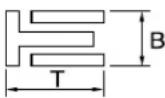 Dimensions (B × T) 1.50 × 2.25 mm (0.06 × 0.09 in) ----End gap (installed) 0.10–0.40 mm (0.004–0.016 in) ---- Dimensions (B × T) 1.50 × 2.25 mm (0.06 × 0.09 in) ----End gap (installed) 0.10–0.40 mm (0.004–0.016 in) ---- | |||
Crankshaft:Crank width "A" 55.95–56.00 mm (2.203–2.205 in) ----Runout limit "C" 0.03 mm (0.0012 in) 0.05 mm (0.002Big end side clearance "D" 0.15–0.45 mm (0.0059–0.0177 in) 0.50 mm (0.02Small end free play "F" 0.4–1.0 mm (0.02–0.04 in) 2.0 mm (0.08 | in)in)in) | ||
| Clutch:Friction plate thickness 2.9–3.1 mm (0.114–0.122 in) 2.7 mm (0.106Quantity 9 ----Clutch plate thickness Quantity 8 ----Warp limit Clutch spring free length Quantity 5 ----Clutch housing thrust clearance Clutch housing radial clearance Clutch release method | in)1.1–1.3 mm (0.043–0.051 in) --------37.0 mm (1.46 in)0.10–0.35 mm (0.0039–0.0138 in) ----0.010–0.044 mm (0.0004–0.0017 in)Inner push, cam push | in)0.1 mm (0.004 in)36.0 mm (1.42 in) ---- | |
| Shifter:Shifter typeGuide bar bending limit | Cam drum and guide bar ---- | ----0.05 mm (0.002 in) | |
| Kickstarter:Type | Kick and ratchet type | ---- | |
| Item | Standard | Limit | |
| Carburetor: USA, CDN, ZA,Type/manufacturer FCR-MX37/KEIHIN ← ----I. D. mark 5UME E0 5UML L0 ----Main jet (M.J) #170 #160 ----Main air jet (M.A.J) #115 ← ----Jet needle (J.N) NJRU NNGU ----Cutaway (C.A) 1.5 ← ----Pilot jet (P.J) #42 #45----Pilot air jet (P.A.J) #70←----Pilot outlet (P.O)ø0.9←----Bypass (B.P)ø1.0←----Valve seat size (V.S)ø3.8←----Starter jet (G.S)#68←----Leak jet (Acc.P) #70 ← ----Float height (F.H)8 mm (0.31 in)←----Engine idle speed1,750–1,950 r/min←----Intake vacuum 31.3–36.7 kPa(235–275 mmHg,9.25–10.83 inHg)← ----Hot starter lever free play3–6 mm (0.12–0.24in)← ---- | AUS, NZ | EUROPE | |
| Lubrication system:Oil filter typePaper type----Oil pump typeTrochoid type----Tip clearance0.12 mm or less (0.0047 in or less)0.20 mm (0.008in)Side clearance0.09–0.17 mm (0.0035–0.0067 in)0.24 mm (0.009in)Housing and rotor clearance0.03–0.10 mm (0.0012–0.0039 in)0.17 mm(0.0067 in) | |||
| Cooling:Radiator core sizeWidth120.2 mm (4.73 in)----Height240 mm (9.45 in)----Thickness22 mm (0.87 in)----Radiator cap opening pressure110 kPa ( 1.1 kg/cm^2 , 15.6 psi)----Radiator capacity (total)0.54 L (0.48 Imp qt, 0.57 US qt)----Water pumpSingle-suction centrifugal pump---- | |||
CHASSIS
| Item Standard | Limit | |||
| Steering system:Steering bearing type | Taper roller bearing | ---- | ||
| Item | Standard | Limit | ||
| Front suspension: | in) | |||
| Front fork travel 300 mm (11.8 in) ---- | ||||
| Fork spring free length 460 mm (18.1 in) 455 mm (17.9) | ||||
| Spring rate, STD K = 4.4 N/mm (0.449 kg/mm, 25.1 lb/in) ---- | ||||
| Optional spring/spacer Yes ---- | ||||
| Oil capacity 648 cm | ^3 (22.8 lmp oz, 21.9 US oz) ---- | |||
| Oil level 132 mm (5.20 in) ---- | ||||
| (From top of outer tube with inner tube and damper rod fully compressed without spring.) | 95-150 mm (3.74-5.91 in) ---- | |||
| Oil grade Suspension oil "S1" ---- | ||||
| Inner tube outer diameter 48 mm (1.89 in) ---- | ||||
| Front fork top end 5 mm (0.20 in) | ---- | |||
| Rear suspension: | USA, CDN | AUS, NZ, ZA | EUROPE | |
| Shock absorber travel | 130 mm (5.12 in) | ← | ← | ---- |
| Spring free length 260 mm (10.24 in) | in) | ← | ← | ---- |
| Fitting length | 249 mm (9.80 in) | 245.0 mm (9.65 in) | 248.5 mm (9.78 in) | ---- |
| Preload length | ||||
| <Min.-Max.> | 1.5-22 mm (0.06-0.87 in) | ← | ← | ---- |
| Spring rate, STD K = 52.0 N/mm | (5.30 kg/mm, 296.8 lb/in) | ← | ← | ---- |
| Optional spring | Yes | ← | ← | ---- |
| Enclosed gas pressure | 1,000 kPa (10 kg/cm ^2 , 142 psi) | ← | ← | ---- |
| Swingarm: | ||||
| Swingarm free play limit | 1.0 mm (0.04 in) | |||
| End | ---- | |||
| Wheel: | USA, CDN, ZA | AUS, NZ, EUROPE | ||
| Front wheel type | Spoke wheel | ← | ---- | |
| Rear wheel type | Spoke wheel | ← | ---- | |
| Front rim size/material | 21 × 1.60/Aluminum | ← | ---- | |
| Rear rim size/material | 18 × 1.85/Aluminum | 18 × 2.15/Aluminum | ---- | |
| Rim runout limit: | ||||
| Radial | ---- | ---- | 2.0 mm (0.08 in) | |
| Lateral | ---- | ---- | 2.0 mm (0.08 in) | |
| Item | Standard | Limit |
| Drive chain:Type/manufacturer DID520VM/DAIDO ----Number of links 113 links + joint ----Chain slack 48–58 mm (1.9–2.3 in) ----Chain length (15 links) ---- 239.3 mm | (9.42 in) | |
| Front disc brake:Disc outside dia.×Thickness 250 × 3.0 mm (9.84 × Pad thickness 4.4 mm (0.17 in) 1.0 mm (0.04 Master cylinder inside dia. 11.0 mm (0.433 in) ----Caliper cylinder inside dia. 27.0 mm (1.063 in) × 2 Brake fluid type DOT #4 | 0.12 in) 250 × 2.5 mm---- ---- | (9.84 × 0.10 in)in) |
| Rear disc brake:Disc outside dia.×Thickness 245 × 4.0 mm (9.65 × Deflection limitPad thickness 6.4 mm (0.25 in) 1.0 mm (0.04 Master cylinder inside dia. 11.0 mm (0.433 in) ----Caliper cylinder inside dia. 25.4 mm (1.000 in) × 1 Brake fluid type DOT #4 | 0.16 in) 245 × 3.5 mm---- 0.15 mm---- ---- | (9.65 × 0.14 in)(0.006 in)in) |
| Brake lever and brake pedal:Brake lever positionBrake pedal height (vertical height above footrest top)Clutch lever free play (lever end)Throttle grip free play | 95 mm (3.74 in)10 mm (0.39 in)8–13 mm (0.31–0.51 in)3–5 mm (0.12–0.20 in) ---- | ---- ---- ---- |
ELECTRICAL
| Item | Standard | Limit | ||
| Ignition system: | ||||
| Advancer type | Electrical | ---- | ||
| CDI: | USA, CDN | AUS, NZ, ZA | EUROPE | |
| Pickup coil resistance (color) | 248–372 Ω at 20 °C (68 °F) (White–Red) | ← | ← | ---- |
| CDI unit-model/manufacturer | 5UM-E0/YA-MAHA | 5UM-F1/YA-MAHA | 5UM-L1/YA-MAHA | ---- |
| Ignition coil: | ||||
| Model/manufacturer | 5UL-10/DENSO | ---- | ||
| Minimum spark gap | 6 mm (0.24 in) | ---- | ||
| Primary coil resistance | 0.08–0.10 Ω at 20 °C (68 °F) | ---- | ||
| Secondary coil resistance | 4.6–6.8 kΩ at 20 °C (68 °F) | ---- | ||
| Charging system: | ||||
| System type AC magneto ---- | ||||
| Model (stator)/manufacturer 5UM 30/YAMAHA ---- | ||||
| Normal output 14 V/120 W at 5,000 r/min ---- | ||||
| Charging coil resistance (color) | 0.288–0.432 Ω at 20 °C (68 °F) (White-Ground) | ---- | ||
| Lighting coil resistance (color) | 0.224–0.336 Ω at 20 °C (68 °F) (Yellow-Ground) | ---- | ||
| Rectifier/regulator: | ||||
| Regulator type Semiconductor short circuit ---- | ||||
| Model/manufacture SH770AA/SHINDENGEN ---- | ||||
| Regulated voltage (AC) 12.5–13.5 V | ---- | |||
| Regulated voltage (DC) | 14.0–15.0 V | ---- | ||
| Rectifier capacity (AC) | 12 A | ---- | ||
| Rectifier capacity (DC) | 8 A | ---- | ||
| Electric starting system: | ||||
| Type | Constant mesh | ---- | ||
| Starter motor: | ||||
| Model/manufacturer | 5UM01/YAMAHA | ---- | ||
| Operation voltage | 12 V | ---- | ||
| Output | 0.35 kW | ---- | ||
| Armature coil resistance | 0.0189–0.0231 Ω at 20 °C (68 °F) | ---- | ||
| Brush overall length | 7 mm (0.28 in) | 3.5 mm (0.14 in) | ||
| Brush quantity | 2 pcs. | ---- | ||
| Spring force | 3.92–5.88 N (400–600 g, 14.1–21.2 oz) | ---- | ||
| Commutator diameter | 17.6 mm (0.69 in) | 16.6 mm (0.65 in) | ||
| Mica undercut (depth) 1.5 mm (0.06 in) | ---- | |||
| Starter relay: | ||||
| Model/manufacturer | RC19-042/MITSUBA | ---- | ||
| Amperage rating | 180 A | ---- | ||
| Coil winding resistance | 4.2–4.6 Ω at 20 °C (68 °F) | ---- | ||
| Starting circuit cut-off relay: | ||||
| Model/manufacturer | ACM33221 M38/MATSUSHITA | ---- | ||
| Coil winding resistance | 75.69–92.51 Ω at 20 °C (68 °F) | ---- | ||
| Fuse (amperage×quantity): | ||||
| Main fuse | 10 A × 1 | ---- | ||
| Reserve fuse | 10 A × 1 | ---- | ||
TIGHTENING TORQUES
ENGINE
TIP
△ - marked portion shall be checked for torque tightening after break-in or before each race.
| Part to be tightened Thread size Q'ty | Tightening torque | ||||
| Nm m·kg ft·lb | |||||
| Spark plug M10S × 1.0 1 13 1.3 9.4 | |||||
| Camshaft cap M6 × 1.0 10 10 1.0 7.2 | |||||
| Cylinder head blind plug screw M12 × 1.0 1 28 2.8 20 | |||||
| Cylinder head (stud bolt) M6 × 1.0 2 7 0.7 5.1 | |||||
| Cylinder head (stud bolt) | M8 × 1.25 1 15 1.5 11 | ||||
| Cylinder head (bolt) | M9 × 1.25 4 38 3.8 27 | ||||
| Cylinder head (nut) | M6 × 1.0 2 10 1.0 7.2 | ||||
| Cylinder head cover | M6 × 1.0 2 10 1.0 7.2 | ||||
| Cylinder | M6 × 1.0 1 10 1.0 7.2 | ||||
| Balancer weight | M6 × 1.0 2 10 1.0 7.2 | ||||
| Balancer shaft driven gear | M14 × 1.0 1 50 5.0 36 | ||||
| Timing chain guide (intake side) | M6 × 1.0 | 2 | 10 | 1.0 | 7.2 |
| Timing chain tensioner | M6 × 1.0 2 10 1.0 7.2 | ||||
| Timing chain tensioner cap bolt | M6 × 1.0 | 1 | 7 | 0.7 | 5.1 |
| Impeller | M8 × 1.25 1 14 1.4 10 | ||||
| Radiator hose clamp | M6 × 1.0 10 2 0.2 1.4 | ||||
| Coolant drain bolt | M6 × 1.0 1 10 1.0 | 7.2 | |||
| Water pump housing | M6 × 1.0 | 4 | 10 | 1.0 | 7.2 |
| Radiator stay | M6 × 1.0 6 10 1.0 7.2 | ||||
| Radiator | M6 × 1.0 4 10 1.0 7.2 | ||||
| Radiator pipe | M6 × 1.0 1 10 1.0 7.2 | ||||
| Oil pump cover | M4 × 0.7 | 1 | 1.7 | 0.17 | 1.2 |
| Oil pump | M6 × 1.0 | 3 10 1.0 | 7.2 | ||
| Oil filter element drain bolt | M6 × 1.0 | 1 | 10 | 1.0 | 7.2 |
| Oil filter element cover | M6 × 1.0 | 2 | 10 | 1.0 | 7.2 |
| Oil strainer (crankcase) | M6 × 1.0 2 10 1.0 | 7.2 | |||
| Oil delivery pipe 1 (M10) | M10 × 1.25 | 1 20 2.0 14 | |||
| Oil delivery pipe 1 (M8) | M8 × 1.25 2 18 1.8 13 | ||||
| Oil hose | M6 × 1.0 | 2 | 8 | 0.8 | 5.8 |
| Oil hose clamp | — | 2 | 2 | 0.2 | 1.4 |
| Oil strainer (oil tank) | M6 × 1.0 | 1 | 9 | 0.9 | 6.5 |
| Oil tank drain bolt | M8 × 1.25 1 18 1.8 13 | ||||
| Oil tank (upper) | M6 × 1.0 | 1 | 7 | 0.7 | 5.1 |
| Oil tank and frame | M6 × 1.0 | 3 | 9 | 0.9 | 6.5 |
| Oil pressure check bolt | M6 × 1.0 1 10 1.0 | 7.2 | |||
| Carburetor joint | M6 × 1.0 | 2 10 1.0 | 7.2 | ||
| Carburetor joint clamp | M4 × 0.7 | 2 | 3 | 0.3 | 2.2 |
| Air filter joint clamp | M6 × 1.0 | 1 | 3 | 0.3 | 2.2 |
| Throttle cable adjust bolt and locknut | M6 × 0.75 | 1 | 4 | 0.4 | 2.9 |
| Throttle cable (pull) | M6 × 1.0 | 1 | 4 | 0.4 | 2.9 |
△
| Part to be tightened | Thread size | Q'ty | Tightening torque | ||
| Nm | m·kg | ft·lb | |||
| Throttle cable (return) M12 × 1.0 1 11 1.1 8.0 | |||||
| Throttle cable cover M5 × 0.8 2 4 0.4 2.9 | |||||
| Hot starter plunger M12 × 1.0 1 2 0.2 1.4 | |||||
| Hot starter cable adjust bolt and locknut M6 × 0.75 1 4 0.4 2.9 | |||||
| Air filter case M6 × 1.0 2 8 0.8 5.8 | |||||
| Air filter joint and air filter case M5 × 0.8 1 4 0.4 2.9 | |||||
| Exhaust pipe M8 × 1.25 2 20 2.0 14 | |||||
| Exhaust pipe protector | M6 × 1.0 3 10 | 1.0 7.2 | |||
| Silencer | M8 × 1.25 2 30 | 3.0 22 | |||
| Silencer clamp | M8 × 1.25 1 16 | 1.6 11 | |||
| Spark arrester | M5 × 0.8 4 7 | 0.7 5.1 | |||
| Silencer cap | M5 × 0.8 6 5 | 0.5 3.6 | |||
| Air induction pipe | M6 × 1.0 1 10 | 1.0 7.2 | |||
| Air induction pipe clamp | M6 × 1.0 1 4 | 0.4 2.9 | |||
| Air cut-off valve assembly and bracket | M6 × 1.0 2 10 | 1.0 7.2 | |||
| Bracket (air cut-off valve) and frame | M6 × 1.0 2 7 | 0.7 5.1 | |||
| Crankcase | M6 × 1.0 11 | 12 | 1.2 8.7 | ||
| Crankcase bearing stopper | M6 × 1.0 11 | 10 | 1.0 7.2 | ||
| Crankcase bearing stopper (crankshaft) | M6 × 1.0 4 14 | 1.4 | 10 | ||
| Left crankcase cover | M6 × 1.0 8 10 | 1.0 7.2 | |||
| Idle gear cover (starter motor) | M6 × 1.0 3 10 | 1.0 7.2 | |||
| Idle gear plate | M6 × 1.0 2 10 | 1.0 7.2 | |||
| Right crankcase cover M6 × 1.0 6 10 1.0 7.2 | |||||
| Clutch cover | M6 × 1.0 7 10 | 1.0 7.2 | |||
| Crankcase oil drain bolt | M10 × 1.25 | 1 20 | 2.0 14 | ||
| Crankshaft end accessing screw | M32 × 1.5 | 1 | — | — | — |
| Timing mark accessing screw | M14 × 1.5 | 1 | — | — | — |
| Drive chain sprocket cover | M6 × 1.0 2 7 | 0.7 5.1 | |||
| Kick shaft ratchet wheel guide | M6 × 1.0 2 12 | 1.2 8.7 | |||
| Kickstarter crank | M8 × 1.25 1 33 | 3.3 24 | |||
| Primary drive gear | M18 × 1.0 1 75 | 7.5 54 | |||
| Clutch spring | M6 × 1.0 5 10 | 1.0 7.2 | |||
| Clutch boss | M16 × 1.0 1 75 | 7.5 54 | |||
| Clutch cable locknut | M8 × 1.25 2 7 | 0.7 5.1 | |||
| Push lever shaft | M6 × 1.0 1 10 | 1.0 7.2 | |||
| Drive sprocket | M18 × 1.0 1 75 | 7.5 54 | |||
| Drive axle oil seal stopper | M6 × 1.0 2 10 | 1.0 7.2 | |||
| Segment | M8 × 1.25 1 30 | 3.0 22 | |||
| Shift guide | M6 × 1.0 2 10 | 1.0 7.2 | |||
| Stopper lever | M6 × 1.0 1 10 | 1.0 7.2 | |||
| Shift pedal | M6 × 1.0 1 12 | 1.2 8.7 | |||
CHASSIS
TIP
△ - marked portion shall be checked for torque tightening after break-in or before each race.
| Part to be tightened Thread size Q'ty | Tightening torque | ||||
| Nm m·kg ft·lb | |||||
| Upper bracket and outer tube M8 × 1.25 4 21 2.1 15 | |||||
| Lower bracket and outer tube M8 × 1.25 4 21 2.1 15 | |||||
| Upper bracket and steering stem M24 × 1.0 1 145 14.5 105 | |||||
| Handlebar upper holder and handlebar lower holder M8 × 1.25 4 28 2.8 20 | |||||
| Handlebar lower holder and upper bracket M10 × 1.25 2 34 3.4 24 | |||||
| Steering stem and steering ring nut | M28 × 1.0 | 1 | Refer to TIP. | ||
| Front fork and front fork cap bolt | M51 × 1.5 2 30 3.0 22 | ||||
| Front fork and base valve | M30 × 1.0 2 55 5.5 40 | ||||
| Front fork cap bolt and damper rod | M12 × 1.25 2 29 2.9 21 | ||||
| Front fork bleed screw and front fork cap bolt | M5 × 0.8 | 2 | 1 | 0.1 | 0.7 |
| Front fork and front fork protector | M6 × 1.0 | 6 | 7 | 0.7 | 5.1 |
| Front fork protector and brake hose holder | M6 × 1.0 | 2 | 7 | 0.7 | 5.1 |
| Throttle grip cap | M5 × 0.8 | 2 | 4 | 0.4 | 2.9 |
| Front brake master cylinder | M6 × 1.0 | 2 | 9 | 0.9 | 6.5 |
| Brake lever mounting bolt | M6 × 1.0 | 1 | 6 | 0.6 | 4.3 |
| Brake lever mounting nut | M6 × 1.0 | 1 | 6 | 0.6 | 4.3 |
| Brake lever position locknut | M6 × 1.0 | 1 | 5 | 0.5 | 3.6 |
| Front brake hose guide and front brake hose guide bracket | M5 × 0.8 | 1 | 4 | 0.4 | 2.9 |
| Front brake hose guide and lower bracket | M6 × 1.0 | 1 | 4 | 0.4 | 2.9 |
| Clutch lever holder | M5 × 0.8 | 2 | 4 | 0.4 | 2.9 |
| Clutch lever mounting nut | M6 × 1.0 | 1 | 4 | 0.4 | 2.9 |
| Hot starter lever holder | M5 × 0.8 | 2 | 4 | 0.4 | 2.9 |
| Hot starter lever mounting nut | M5 × 0.8 | 1 | 2 | 0.2 | 1.4 |
| Front brake master cylinder cap | M4 × 0.7 | 2 | 2 | 0.2 | 1.4 |
| Front brake hose union bolt | M10 × 1.25 2 30 3.0 22 | ||||
| Front brake caliper | M8 × 1.25 2 23 2.3 17 | ||||
| Front brake caliper and brake hose holder | M6 × 1.0 | 1 | 10 | 1.0 | 7.2 |
| Pad pin plug | M10 × 1.0 | 2 | 3 | 0.3 | 2.2 |
| Front brake caliper and pad pin | M10 × 1.0 1 18 1.8 13 | ||||
| Rear brake caliper and pad pin | M10 × 1.0 1 18 1.8 13 | ||||
| Brake caliper and bleed screw | M8 × 1.25 | 2 | 6 | 0.6 | 4.3 |
| Front wheel axle and axle nut | M16 × 1.5 1 90 9.0 65 | ||||
| Front wheel axle holder | M8 × 1.25 4 21 2.1 15 | ||||
| Front brake disc | M6 × 1.0 | 6 | 12 | 1.2 | 8.7 |
| Rear brake disc | M6 × 1.0 | 6 | 14 | 1.4 | 10 |
| Brake pedal | M8 × 1.25 1 26 2.6 19 | ||||
| Rear brake master cylinder | M6 × 1.0 | 2 | 10 | 1.0 | 7.2 |
| Rear brake master cylinder cap | M4 × 0.7 | 2 | 2 | 0.2 | 1.4 |
| Rear brake hose union bolt | M10 × 1.25 2 30 3.0 22 | ||||
| Rear wheel axle and axle nut | M20 × 1.5 | 1 | 125 | 12.5 | 90 |
| Nipple (spoke) | — | 72 | 3 | 0.3 | 2.2 |
| Part to be tightened | Thread size | Q'ty | Tightening torque | ||
| Nm | m·kg | ft·lb | |||
| Rear wheel sprocket M8 × 1.25 6 50 5.0 36 | |||||
| Rear brake disc cover M6 × 1.0 2 10 1.0 7.2 | |||||
| Rear brake caliper protector M6 × 1.0 2 7 0.7 5.1 | |||||
| Drive chain puller adjust bolt and locknut M8 × 1.25 2 19 1.9 | 13 | ||||
| Engine mounting: | |||||
| Engine and engine bracket (front) M10 × 1.25 1 53 5.3 38 | |||||
| Engine and frame (lower) M10 × 1.25 1 53 5.3 38 | |||||
| Upper engine bracket and frame | M8 × 1.25 4 34 3.4 24 | ||||
| Lower engine bracket and frame | M8 × 1.25 4 34 3.4 24 | ||||
| Engine and engine bracket (upper) | M10 × 1.25 1 55 5.5 40 | ||||
| Engine guard | M6 × 1.0 3 7 0.7 5.1 | ||||
| Regulator | M6 × 1.0 2 7 0.7 | 5.1 | |||
| Pivot shaft and nut | M16 × 1.5 1 85 8.5 61 | ||||
| Relay arm and swingarm | M14 × 1.5 1 70 7.0 50 | ||||
| Relay arm and connecting rod | M14 × 1.5 1 80 8.0 58 | ||||
| Connecting rod and frame | M14 × 1.5 1 80 8.0 58 | ||||
| Rear shock absorber and frame | M10 × 1.25 1 56 5.6 40 | ||||
| Rear shock absorber and relay arm | M10 × 1.25 1 53 5.3 38 | ||||
| Rear frame (upper) | M8 × 1.25 1 38 3.8 27 | ||||
| Rear frame (lower) | M8 × 1.25 2 32 3.2 23 | ||||
| Swingarm and brake hose holder | M5 × 0.8 4 3 0.3 2.2 | ||||
| Swingarm and patch | M4 × 0.7 4 2 0.2 1.4 | ||||
| Upper drive chain tensioner | M8 × 1.25 1 16 1.6 11 | ||||
| Lower drive chain tensioner | M8 × 1.25 1 16 1.6 11 | ||||
| Drive chain support | M6 × 1.0 3 7 0.7 | 5.1 | |||
| Seal guard and swingarm | M5 × 0.8 4 6 0.6 4.3 | ||||
| Fuel tank | M6 × 1.0 2 9 0.9 6.5 | ||||
| Fuel cock | M6 × 1.0 2 4 0.4 2.9 | ||||
| Seat set bracket and fuel tank | M6 × 1.0 1 7 0.7 5.1 | ||||
| Fuel tank bracket and fuel tank | M6 × 1.0 4 7 0.7 5.1 | ||||
| Air scoop and fuel tank | M6 × 1.0 6 7 0.7 5.1 | ||||
| Air scoop and radiator guard (lower) | M6 × 1.0 | 2 | 6 | 0.6 | 4.3 |
| Front fender | M6 × 1.0 4 7 0.7 5.1 | ||||
| Rear fender (front) | M6 × 1.0 2 7 0.7 5.1 | ||||
| Rear fender (rear) | M6 × 1.0 2 11 1.1 8.0 | ||||
| Side cover | M6 × 1.0 2 7 0.7 5.1 | ||||
| Seat | M8 × 1.25 2 22 2.2 16 | ||||
| Multi-function display bracket and upper bracket | M6 × 1.0 2 7 0.7 5.1 | ||||
| Multi-function display | M5 × 0.8 2 4 0.4 2.9 | ||||
| Plate 1 and front fork protector | M5 × 0.8 2 4 0.4 2.9 | ||||
| Plate 2 and front fork protector | — | 2 | 0.5 | 0.05 | 0.36 |
| Speed sensor lead holder and lower bracket | M6 × 1.0 1 13 1.3 9.4 | ||||
| Speed sensor lead holder and clamp | M6 × 1.0 1 7 0.7 5.1 | ||||
| Headlight body and headlight unit | — | 2 1 0.1 0.7 | |||
| Headlight M6 × 1.0 2 7 0.7 5.1 | |||||
| Taillight — 3 1 0.1 0.7 | |||||
| Taillight lead clamp and rear fender — 3 0.5 0.05 0.36 | |||||
| Catch tank (upper) | M6 × 1.0 | 1 | 16 | 1.6 | 11 |
| Catch tank (lower) | M6 × 1.0 | 1 | 7 | 0.7 | 5.1 |
| Footrest bracket and frame | M10 × 1.25 | 4 | 55 | 5.5 | 40 |
| Sidestand | M10 × 1.25 | 1 | 25 | 2.5 | 18 |
| Front reflector (For CDN) | M6 × 1.0 | 2 4 0.4 | 2.9 | ||
| Rear reflector (For CDN) | M5 × 0.8 | 3 2 0.2 | 1.4 | ||
TIP
-
First, tighten the steering ring nut approximately 38 Nm (3.8 m·kg, 27 ft·lb) by using the steering nut wrench, then loosen the steering ring nut one turn.
-
Retighten the steering ring nut 7 Nm (0.7 m•kg, 5.1 ft•lb).
ELECTRICAL
| Part to be tightened | Thread size | Q'ty | Tightening torque | ||
| Nm | m•kg ft•lb | ||||
| Stator | M5 × 0.8 2 7 | 0.7 5.1 | |||
| Holder (AC magneto lead) | M5× 0.8 | 2 7 0.7 | 5.1 | ||
| Rotor | M12 × 1.25 | 1 | Refer to TIP. | ||
| Neutral switch | M5 × 0.8 | 2 4 0.4 | 2.9 | ||
| Starter motor | M6 × 1.0 | 2 | 10 | 1.0 | 7.2 |
| Starter relay terminal | M6 × 1.0 | 2 4 0.4 | 2.9 | ||
| Negative lead and cylinder head | M6 × 1.0 1 10 | 1.0 | 7.2 | ||
| Pickup coil | M6 × 1.0 | 2 | 10 | 1.0 | 7.2 |
TIP
Tighten the rotor nut to 65 Nm (6.5 m·kg, 47 ft·lb), loosen and retighten the rotor nut to 65 Nm (6.5 m·kg, 47 ft·lb).
GENERAL TORQUE SPECIFICATIONS
This chart specifies torque for standard fasteners with standard I.S.O. pitch threads. Torque specifications for special components or assemblies are included in the applicable sections of this book. To avoid warpage, tighten multi-fastener assemblies in a crisscross fashion, in progressive stages, until full torque is reached. Unless otherwise specified, torque specifications call for clean, dry threads. Components should be at room temperature.

A. Distance between flats
B. Outside thread diameter
| A(Nut) | B(Bolt) | TORQUE SPECIFICATION | |
| Nm m·kg ft·lb | |||
| 10mm | 6 mm | 6 0.6 4.3 | |
| 12mm | 8 mm | 15 1.5 11 | |
| 14mm | 10mm | 30 3.0 22 | |
| 17mm | 12mm | 55 5.5 40 | |
| 19mm | 14mm | 85 8.5 61 | |
| 22mm | 16mm | 130 13 94 | |
DEFINITION OF UNITS
| Unit Read Definition Measure | |||
| mm | millimeter 10 | ^-3 meter Length | |
| cm | centimeter | 10^-2 meter Length | |
| kg | kilogram 10 | ^3 gram | Weight |
| N | Newton | 1 kg × m/sec^2 | Force |
| Nm | Newton meter | N × m | Torque |
| m·kg | Meter kilogram | m × kg | Torque |
| Pa | Pascal | N/m^2 | Pressure |
| N/mm | Newton per millimeter | N/mm | Spring rate |
| L | Liter | — | Volume or capacity |
| cm^3 | Cubic centimeter | — | Volume or capacity |
| r/min | Revolution per minute | — | Engine speed |
LUBRICATION DIAGRAMS

text_image
Technical schematic diagram of a mechanical assembly with labeled components A, B, C and numbered parts 1 through 8.- Oil filter element
- Oil pump
- Drive axle
- Main axle
- Intake camshaft
- Exhaust camshaft
- Oil tank
- Oil delivery pipe
A. To oil tank

text_image
E E ③ ④ A
text_image
Technical schematic diagram of a mechanical assembly with labeled parts ① and ②- Crankshaft
- Oil filter element
- Oil tank
- Oil hose
A. From oil pump
CABLE ROUTING DIAGRAM

text_image
Technical diagram of a mechanical assembly with numbered components and labeled parts (A, B, C-C)- Fuel tank breather hose
- Clamp
- Diode
- Hot starter cable
- Wire harness
- Hump (frame)
- Cylinder head breather hose
- Throttle position sensor lead
-
Neutral switch lead
-
Oil hose
- Clutch cable
- Starter motor lead
- Cable guide
- Negative battery lead
- AC magneto lead
- Brake hose
- Rectifier/regulator lead
-
Carburetor breather hose
-
Carburetor overflow hose
- Catch tank breather hose
- Hot starter cable protector
- Rubber cap
A. Insert the end of the fuel tank breather hose into the hole in the steering stem.
B. Fasten the throttle cable, hot starter cable and rectifier/regulator lead onto the frame. Locate the clamp under the throttle cable on the right side of the frame, and face its ends, as well as the tie ends, downward.
C. Fasten the diode (at the marking), throttle cable and hot starter cable onto the frame. Locate the clamp end facing toward the lower right of the frame and with the tie end facing downward.
D. Fasten the wire harness, throttle position sensor lead, starter motor lead and negative battery lead onto the frame. Pass the clamp through the hole in the stay (air cut-off valve). Locate the clamp end facing toward the lower side of the frame and cut off the tie end.
E. Pass the carburetor breather hoses, carburetor overflow hose and catch tank breather hose between the connecting rod and cross tube (frame).
F. Fasten the neutral switch lead and oil hose together with the plastic locking ties and cut off the tie ends.
G. Fasten the neutral switch lead and AC magneto lead onto the frame. Locate the clamp end facing toward the outside of the frame and tie end facing toward the rear of the frame.
H. Pass the clutch cable through the cable guide.
I. Fasten the starter motor lead, AC magneto lead and neutral switch lead onto the frame. Locate the clamp end facing toward the rear of the frame and cut off the tie end.
J. Fasten the clutch cable, starter motor lead, negative battery lead, AC magneto lead and neutral switch lead onto the frame. Locate the clamp end facing toward the rear of the frame and cut off the tie end.
K. Pass the neutral switch lead and AC magneto lead on the inside of the wire harness.
L. Fasten the clutch cable, AC magneto lead and neutral switch lead onto the frame. Locate the clamp end near the clutch cable and cut off the tie end.
M. Pass the clutch cable and wire harness through the cable guide.
N. Locate the couplers in the frame recess.
O. Pass the carburetor breather hoses, carburetor overflow hose and catch tank breather hose so that the hoses do not contact the rear shock absorber.
P. Secure the coupler by pushing it into the hole in the headlight unit.
Q. Fasten the throttle position sensor lead and the hot starter cable.
R. Locate the clamp between the hot starter cable protector and rubber cap.

text_image
YAMAHA- Throttle cable (pull)
- Throttle cable (return)
- Catch tank hose
- Ignition coil
- Clamp
- Air induction hose (air cut-off valve - rear of cylinder head)
- Catch tank breather hose
A. Cross the pull and push throttle cables.
B. Fasten the catch tank hose and air induction hose (air cut-off valve-rear of cylinder head) onto the frame. Locate the clamp end facing toward the lower side of the frame and cut off the tie end.
C. Fasten the catch tank breather hose and carburetor breather hoses together.
D. Pass the carburetor breather hose (of the throttle cable cover) through the hose holder.

text_image
Technical diagram of a mechanical assembly with labeled parts and a detailed top-down view showing internal components.- Brake master cylinder
- Brake hose holder
- Brake hose
A. Install the brake hose so that its pipe portion directs as shown and lightly touches the projection on the brake caliper.
B. Pass the brake hose into the brake hose holders.
C. If the brake hose contacts the spring (rear shock absorber), correct its twist.
D. Install the brake hose so that its pipe portion directs as shown and lightly touches the projection on the brake master cylinder.

text_image
Technical diagram of a jet engine internal structure with labeled components
text_image
Technical diagram of a vehicle's internal components with numbered labels for identification- Clamp
- Positive battery lead
- Battery
- Negative battery lead
- Taillight coupler
- CDI unit coupler (6-pin)
- CDI unit coupler (3-pin)
- CDI unit coupler (6-pin)
A. Fasten the wire harness, negative battery lead and starter motor lead to the upper engine bracket (left side). Locate the clamp end facing toward the upper side of the frame with the tie end cut off on the inside of the frame.
B. Fasten the wire harness, negative battery lead and starter motor lead to the upper engine bracket (left side). Locate the clamp end facing toward the upper side of the frame with the tie end cut off on the inside of the frame. Clamp the wire harness and negative lead at the marking.
C. Pass the starter motor lead through the hole in the relay holder.
D. Fit the cover securely.
E. Connect the wire harness to the starter relay.
F. Fasten the catch tank breather hose and catch tank hose to the rear frame. Clamp them close to where they are joined to the frame. Fasten the pipe tightly enough not to crush it. Locate the clamp end facing toward the rear of the frame with the tie end facing downward.
G. Fasten the (three) CDI unit leads and taillight lead to the rear frame. Locate the clamp end facing toward the upper side of the frame and cut off the tie end.
H. Connect the negative battery lead to the battery negative terminal.
I. Connect the negative battery lead to the wire harness.
J. Fasten the wire harness to the rear frame. Locate the clamp end facing toward the upper side of the frame and the tie end toward the inside of the frame. Clamp the wire harness at the marking.
K. Pass the wire harness, starter relay lead, starting circuit cut-off relay lead and negative battery lead through the hole in the relay holder.
L. Fasten the (three) CDI unit leads and taillight lead to the rear frame. Locate the clamp end facing toward the lower side of the frame and cut off the tie end.
M. Fasten the taillight lead to the rear frame. Locate the clamp end facing toward the upper side of the frame and cut off the tie end.
N. Do not allow the taillight lead to slacken.
O. Locate the CDI unit lead between the CDI unit and rear fender.
P. Locate the CDI unit coupler in the clearance between the upper side of the CDI unit and lower side of the catch tank stay.
Q. Locate the CDI unit lead between the CDI unit and rear frame.

text_image
Technical diagram of a mechanical device with numbered components and labeled parts, including top, side, and front views.- Throttle cable
- Clamp
- Brake hose
- Clutch cable
- Hose guide
- Main switch coupler
- Wire harness
- Headlight coupler
- Hot starter cable
- Multi-function display bracket
-
Main switch
-
Upper bracket
- Clutch switch coupler
- Engine stop switch coupler
- Multi-function display coupler
- Start switch coupler
- Speed sensor coupler
- Speed sensor lead
A. Fasten the start switch lead to the handlebar with the plastic bands.
B. Fasten the engine stop switch lead and clutch switch lead to the handlebar with the plastic bands.
C. Pass the brake hose through the hose guides.
D. Secure the coupler by inserting it into the multi-function display bracket.
E. Pass the throttle cables, clutch cable and hot starter cable between the upper bracket and multi-function display bracket.
F. Fasten the multi-function display leads to the bracket. Cut off the tie end.
G. Secure the coupler by pushing it into the hole in the multi-function display bracket.
H. Secure the wire harness clip by pushing it into the hole in the multi-function display bracket on the inside.
1. Fasten the wire harness to the multi-function display bracket. Cut off the tie end.
J. Fasten the main switch lead (wire harness side) to the multifunction display bracket. Locate the clamp end facing toward the lower side of the frame and cut off the tie end.
K. Pass the speed sensor lead through the guide on the outside of the front fork.
PERIODIC MAINTENANCE CHART FOR THE EMISSION
CONTROL SYSTEM (For Canada)
REGULAR INSPECTION AND ADJUSTMENTS
PERIODIC MAINTENANCE CHART FOR THE EMISSION CONTROL SYSTEM (For Canada)
TIP
• From 4,200 mi (7,000 km) or 9 months, repeat the maintenance intervals starting from 1,800 mi (3,000 km) or 3 months.
- Items marked with an asterisk should be performed by a Yamaha dealer as they require special tools, data and technical skills.
| No. | ITEM CHECKS AND MAINTENANCE | ICE JOBS | INITIAL | ODOMETER READINGS | ||
| 600 mi (1,000 km) or 1 month | 1,800 mi (3,000 km) or 3 months | 3,000 mi (5,000 km) or 6 months | ||||
| 1 * | Fuel line | Check fuel hoses for cracks or damage.Replace if necessary. | √ | √ | √ | |
| 2 | Spark plug | Check condition.Adjust gap and clean. | √ | √ | √ | |
| 3 * | Valve clearance | Check and adjust valve clearance when engine is cold. | √ | √ | √ | |
| 4 * | Air filter element | Clean with solvent and apply foam air-filter oil or equivalent oil.Replace if necessary. | √ | √ | √ | |
| 5 * | Breather system | Check ventilation hose for cracks or damage and drain any deposits.Replace if necessary. | √ | √ | √ | |
| 6 * | Carburetor | Check engine idling speed and starter operation.Adjust if necessary. | √ | √ | √ | |
| 7 | Exhaust system | Check for leakage.Replace gasket(s) if necessary. | √ | √ | √ | |
| 8 | Engine oil Change (warm engine before draining). √ √ √ | |||||
| 9 | Engine oil filter element Replace. √ | √ √ | ||||
| 10 | Engine oil strainer Clean. √ √ √ | |||||
| 11 * | Air induction system | Check the hose for damage.Replace any damaged parts if necessary. | √ | √ | ||
Tighten if
GENERAL MAINTENANCE AND LUBRICATION CHART (For Canada)
| No. | ITEM CHECKS AND MAINTENANCE | ICE JOBS | INITIAL | ODOMETER READINGS | ||
| 600 mi (1,000 km) or 1 month | 1,800 mi (3,000 km) or 3 months | 3,000 mi (5,000 km) or 6 months | ||||
| 1 | Clutch | Check operation.Adjust or replace cable. | √ | √ | √ | |
| 2* | Cooling system | Check hoses for cracks of damage.Replace if necessary. | √ | √ | √ | |
| Replace with ethylene glycol anti-freeze coolant every 1 year. | Every 1 year | |||||
| 3* | Spark arrester Clean. √ | |||||
| 4* | Front brake | Check operation, fluid level, and for fluid leakage.Replace brake pads if necessary. | √ | √ | √ | |
| Replace brake fluid every 1 year. Every 1 year | ||||||
| 5* | Rear brake | Check operation, fluid level, and for fluid leakage.Replace brake pads if necessary. | √ | √ | √ | |
| Replace brake fluid every 1 year. Every 1 year | ||||||
| 6* | Brake hoses | Check for cracks or damage. √ √ | ||||
| Replace. Every 4 years | ||||||
| 7* | Wheels | Check runout, spoke tightness and for damage.Tighten spokes if necessary. | √ | √ | √ | |
| 8 | * | Tires | Check tread depth and for damage.Replace if necessary.Check air pressure.Correct if necessary. | √ | √ | √ |
| 9* | Wheel bearings | Check bearings for smooth operation.Replace if necessary. | √ | √ | √ | |
| 10* | Swingarm pivot bearings | Check bearing assemblies for looseness.Moderately repack with lithium-soapbased grease. | √ | √ | √ | |
| 11 | Drive chain | Check chain slack/alignment and condition.Adjust and lubricate chain with a special O-ring chain lubricant thoroughly. | Every ride | |||
| 12* | Steering bearings | Check bearing assemblies for looseness.Moderately repack with lithium-soapbased grease every 1,200 mi (2,000 km) or 12 months (whichever comes first). | √ | √ | √ | |
| 13 | Brake and clutch lever pivot shafts | Apply lithium-soap-based grease (all-purpose grease) lightly. | √ | √ | √ | |
| 14 | Brake pedal pivot shafts | Apply lithium-soap-based grease (all-purpose grease) lightly. | √ | √ | √ | |
| No. | ITEM CHECKS AND MAINTENANCE | CE JOBS | INITIAL | ODOMETER READINGS | |
| 600 mi (1,000 km) or 1 month | 1,800 mi (3,000 km) or 3 months | 3,000 mi (5,000 km) or 6 months | |||
| 15 | Sidestand pivot | Check operation.Apply lithium-soap-based grease (all-purpose grease) lightly. | √ | √ | √ |
| 16 | Front fork | Check operation and for oil leakage.Replace if necessary. | √ | √ | |
| 17 | Shock absorber assembly | Check operation and for oil leakage.Replace if necessary. | √ | √ | |
| 18 | Rear suspension link pivots Apply molybdenum disulfide grease lightly. √ | √ | |||
| 19 | Control cables | Apply Yamaha chain and cable lube or engine oil 10W-30 thoroughly. | √ | √ | √ |
| 20 | Throttle grip housing and cable | Check operation and free play.Lubricate the throttle grip housing and cable. | √ | √ | √ |
| 21 | Chassis fasteners | Check all chassis fitting and fasteners.Correct if necessary. | √ | √ | √ |
| 22 | Battery Check terminal for looseness | and corrosion. √ √ | |||
TIP
- The air filter needs more frequent service if you are riding in unusually wet or dusty areas.
• Hydraulic brake service
- After disassembling the brake master cylinders and calipers, always change the fluid. Regularly check the brake fluid levels and fill the reservoirs as required.
- Every two years replace the internal components of the brake master cylinders and calipers, and change the brake fluid.
- Replace the brake hoses every four years and if cracked or damaged.
MAINTENANCE INTERVALS FOR COMPETITION USE
TIP
- The following schedule is intended as a general guide to maintenance and lubrication. Bear in mind that such factors as weather, terrain, geographical location, and individual usage will alter the required maintenance and lubrication intervals. If you are a doubt as to what intervals to follow in maintaining and lubricating your machine, consult your Yamaha dealer.
- Periodic inspection is essential in making full use of the machine performance. The service life of the parts varies substantially according to the environment in which the machine runs (e.g., rain, dirt, etc.). Therefore, earlier inspection is required by reference to the list below.
| Item | After break-in | Every race | Every third (or 500 km) | Every fifth (or 1,000 km) | As required | Remarks |
| ENGINE OILReplace ● | ● | |||||
| VALVESCheck the valve clearances ●InspectReplace | ● | ● | ● | The engine must be cold.Check the valve seats and valve stems for wear. | ||
| VALVE SPRINGSInspectReplace | ● | ● | Check the free length and the tilt. | |||
| VALVE LIFTERSInspect ● Check for scratches and wear.Replace ● | ||||||
| CAMSHAFTS Inspect the camshaft surface.Inspect ● Inspect the decompression system.Replace ● | ||||||
| CAMSHAFT SPROCKETSInspect ● Check for wear on the teeth and forReplace ● | damage. | |||||
| PISTONInspect ● ● Inspect crack.Clean ● Inspect carbon deposits and eliminateReplace ● It is recommended that the piston pin | them.and ring are also replaced at the same time. | |||||
| PISTON RINGInspect ● Check ring end gap.Replace ● ● | ||||||
| PISTON PINInspect ●Replace ● | ||||||
| CYLINDER HEAD Inspect carbon deposits and eliminateInspect and clean ● Change gasket. | them. | |||||
| CYLINDERInspect and clean ● Inspect score marks.Replace ● Inspect wear. | ||||||
| CLUTCHInspect and adjustReplace ● | ● | ● | Inspect housing, friction plate, clutch plate and spring. | |||
| TRANSMISSIONInspect ●Replace bearing | ● | |||||
| SHIFT FORK, SHIFT CAM, GUIDE BARInspect ● Inspect wear. | ||||||
| ROTOR NUTRetighten | ● | ● | ||||
| MUFFLERInspect and retightenCleanReplace ● | ● | ● | ● |
| Item | After break-in | Every race | Every third (or 500 km) | Every fifth (or 1,000 km) | As required | Remarks | |
| CRANKInspect and clean ● ● | |||||||
| CARBURETORInspect, adjust and clean ● | ● | ||||||
| AIR INDUCTION SYSTEMInspect and clean ● ● | ● | ● | |||||
| SPARK PLUGInspect and clean ●Replace ● | ● | ||||||
| DRIVE CHAIN Use chain lube.Lubricate, slack, alignmentReplace ● | ● | ● | Chain slack: 48–58 mm (1.9–2.3 in) | ||||
| COOLING SYSTEMCheck coolant level and leakage●Check radiator cap operation ●Replace coolant ● Every two yearsInspect hoses ● | |||||||
| OUTSIDE NUTS AND BOLTSRetighten ● ● | Refer to "STARTING AND BREAK- | IN" section in the CHAPTER 1. | |||||
| AIR FILTERClean and lubricateReplace ● | ● | ● | Use foam air-filter oil or equivalent oil. | ||||
| OIL FILTERReplace ● | ● | ||||||
| ENGINE GUARDReplace ● Breakage | |||||||
| FRAMEClean and inspect | ● | ● | |||||
| FUEL TANK, COCKClean and inspect | ● | ● | |||||
| BRAKESAdjust lever position and pedal heightLubricate pivot pointCheck brake disc surfaceCheck fluid level and leakageRetighten brake disc bolts, cali-per bolts, master cylinder bolts and union boltsReplace padsReplace brake fluid | ●●●●●●●●●●●●●●●●●●●●●●●●●●●●●●●●●●●●●●●●●●●●●●●●●●●●●●●●●●●●●●●●●●●●●●●●●●●●●●●●●●●●●●●●●●●●●●●●●●●●○●●●●●●●●●●●●●●●●●●●●●●●●●●●●●●●●●●●●●●●●●●●●●●●●●●●●●●●●●●●●●●●●●●●●●●●●●●●●●●●●●●●●●●●●●●●●●●●●●●● ●●●●●●●●●●●●●●●●●●●●●●●●●●●●●●●●●●●●●●●●●●●●●●●●●●●●●●●●●●●●●●●●●●●●●●●●●●●●●●●●●●●●●●●●●●●●●●●●●●●●—●●●●●●●●●●●●●●●●●●●●●●●●●●●●●●●●●●●●●●●●●●●●●●●●●●●●●●●●●●●●●●●●●●●●●●●●●●●●●●●●●●●●●●●●●●●●●●●●●●●——●●●●●●●●●●●●●●●●●●●●●●●●●●●●●●●●●●●●●●●●●●●●●●●●●●●●●●●●●●●●●●●●●●●●●●●●●●●●●●●●●●●●●●●●●●●●●●●●●●● | Refer to "STARTING AND BREAK- | |||||
| Item | After break-in | Every race | Every third (or 500 km) | Every fifth (or 1,000 km) | As required | Remarks | |
| FRONT FORKSInspect and adjust ● Replace oil ●Replace oil seal ● | Suspension oil "S1" | ||||||
| FRONT FORK OIL SEAL AND DUST SEALClean and lube ● | Lithium | base grease | |||||
| PROTECTOR GUIDEReplace ● | |||||||
| REAR SHOCK ABSORBERInspect and adjust ● Lube ●Retighten ● | (After rain ride) ● | Molybdenum disulfide grease | |||||
| DRIVE CHAIN GUIDE AND ROLLERSInspect ● ● | |||||||
| SWINGARMInspect, lube and retighten | Molybdenum disulfide grease | ||||||
| RELAY ARM, CONNECTING RODInspect, lube and retighten | Molybdenum disulfide grease | ||||||
| SIDESTANDLubricate ● Lithium base grease | |||||||
| STEERING HEADInspect free play and retighten●Clean and lubeReplace bearing | ● | Lithium base grease | |||||
| TIRE, WHEELSInspect air pressure, wheel run-out, tire wear and spoke loose-nessRetighten sprocket boltInspect bearingsReplace bearingsLubricate | ● | Lithium base grease | |||||
| THROTTLE, CONTROL CABLECheck routing and connectionLubricate | Yamaha cable lube or SAE 10W-40 motor oil | ||||||
| HOT STARTER, CLUTCH LEVERInspect free play | ● | ||||||
| BATTERYCheck terminal for looseness and corrosion | ● | ||||||
Before riding for break-in operation or practice, make sure the machine is in good operating condition.
Before using this machine, check the following points.
GENERAL INSPECTION AND MAINTENANCE
| Item Routine Page | ||
| Coolant | Check that coolant is filled up to the radiator cap. Check the cooling system for leakage. | P.3-11 – 12 |
| Fuel | Check that a fresh gasoline is filled in the fuel tank. Check the fuel line for leakage. | P.1-18 |
| Engine oil | Check that the oil level is correct. Check the crankcase and oil line for leakage. | P.3-14 – 15 |
| Gear shifter and clutch | Check that gears can be shifted correctly in order and that the clutch operates smoothly. | P.3-12 – 13 |
| Throttle grip/Housing | Check that the throttle grip operation and free play are correctly adjusted. Lubricate the throttle grip and housing, if necessary. | P.3-13 |
| Brakes Check the play of front brake and effect of front and rear brake. P.3-19 – 22 | ||
| Drive chain | Check drive chain slack and alignment. Check that the drive chain is lubricated properly. | P.3-22 – 23 |
| Wheels | Check for excessive wear and tire pressure. Check for loose spokes and have no excessive play. | P.3-26 – 27 |
| Steering | Check that the handlebar can be turned smoothly and have no excessive play. | P.3-27 |
| Front forks and rear shock absorber | Check that they operate smoothly and there is no oil leakage. | P.3-23 – 26 |
| Cables (wires) | Check that the clutch and throttle cables move smoothly. Check that they are not caught when the handlebars are turned or when the front forks travel up and down. | — |
| Exhaust pipe | Check that the exhaust pipe is tightly mounted and has no cracks. | P.3-10 – 11 |
| Rear wheel sprocket | Check that the rear wheel sprocket tightening bolt is not loose. | P.3-22 |
| Lubrication Check for smooth operation. Lubricate if necessary. P.3-28 | ||
| Bolts and nuts Check the chassis and engine for loose bolts and nuts. P.1-20 | ||
| Lead connectors | Check that the AC magneto, CDI unit, and ignition coil are connected tightly. | P.1-7 |
| Settings | Is the machine set suitably for the condition of the course and weather or by taking into account the results of test runs before riding? Are inspection and maintenance completely done? | P.4-1 – 10 |
ENGINE
REMOVING THE SEAT, FUEL TANK AND SIDE COVERS

other
| Component | Diameter (Nm) | |-----------|---------------| | Top Left | 9 Nm (0.9 m · kg, 6.5 ft · lb) | | Top Right | 7 Nm (0.7 m · kg, 5.1 ft · lb) | | Bottom Left | 22 Nm (2.2 m · kg, 16 ft · lb) | | Bottom Right | 9 Nm (0.9 m · kg, 6.5 ft · lb) | | Bottom Right | 7 Nm (0.7 m · kg, 5.1 ft · lb) | | Bottom Right | 4 Nm (0.4 m · kg, 2.9 ft · lb) | | Bottom Right | 7 Nm (0.7 m · kg, 5.1 ft · lb) | | Bottom Right | 7 Nm (0.7 m · kg, 5.1 ft · lb) | Order Part name Q'ty Remarks Turn the fuel cock to "OFF". Disconnect the fuel hose. Air scoop (left and right) 2 Bolt (fuel tank) 2 Fuel tank 1 Left side cover 1 Open the air filter case cover. Right side cover 1 Refer to removal section. Headlight coupler 1 Headlight 1REMOVING THE SIDE COVER
-
Remove:
-
Bolt (side cover)
- Right side cover "1"
TIP
Draw the side cover backward to remove it because its claw "a" is inserted in the air filter case.

text_image
Technical diagram showing a mechanical component with labeled parts and an arrow indicating direction or forceREMOVING THE EXHAUST PIPE AND SILENCER

other
| Component | Name | Dimension (m) | |-----------|-------|---------------| | New | 1 | 5 | | New | 2 | 7 | | New | 3 | 4 | | New | 5 | 3 | | New | 7 | 7 | | New | 9 | 8 | | New | 10 | 6 | | New | 16 | 9 | | New | 20 | 7 | | New | 30 | 2 | | New | 16 | 1 | | New | 10 | 1 | | New | 16 | 1 | | New | 20 | 1 | | New | 30 | 1 | | Silencer clamp | 1 | Only loosening. | | Silencer clamp | 2 | Only loosening. | | Silencer clamp | 3 | Only loosening. | | Silencer clamp | 4 | Only loosening. | | Silencer clamp | 5 | Only loosening. | | Silencer clamp | 6 | Only loosening. | | Silencer clamp | 7 | Only loosening. | | Silencer clamp | 8 | Only loosening. | | Silencer clamp | 9 | Only loosening. | | Silencer clamp | 10 | Only loosening. | The image displays a schematic diagram of a vehicle's components and parts. The labels for the components are 'New' or '30 Nm'. The numbers inside the diagram are explicitly labeled as 'Nm'. The text below is 'Order Part name Q'ty Remarks'. The table below is a table for the same part names, but the data is already in English.CHECKING THE SILENCER AND EXHAUST PIPE
1. Inspect:
- Gasket "1" Damage → Replace.

natural_image
Technical line drawing of a pipe fitting with a separate inset showing a ring and a numbered component (no text or symbols)INSTALLING THE SILENCER AND EXHAUST PIPE
1. Install:
• Gasket New
- Exhaust pipe "1"
- Nut (exhaust pipe) "2"

Nut (exhaust pipe): 20 Nm (2.0 m·kg, 14 ft·lb)
TIP
First, temporarily install both nuts, then tighten either of these nuts to 13 Nm (1.3 m·kg, 9.4 ft·lb) and the other to 20 Nm (2.0 m·kg, 14 ft·lb), and then come back to the first one and retighten it to 20 Nm (2.0 m·kg, 14 ft·lb).

text_image
Technical diagram of a mechanical assembly with numbered components, likely for assembly or maintenance reference.2. Install:
- Silencer clamp "1"

Silencer clamp: 16 Nm (1.6 m·kg, 11 ft·lb)
- Gasket "2" New
- Silencer "3"
- Washer "4"
- Bolt (silencer) "5"

Bolt (silencer): 30 Nm (3.0 m·kg, 22 ft·lb)

text_image
Technical diagram of a vehicle's rear suspension system with numbered components and a 'New' labelCHECKING THE COOLANT LEVEL
WARNING
Do not remove the radiator cap "1", drain bolt and hoses when the engine and radiator are hot. Scalding hot fluid and steam may be blown out under pressure, which could cause serious injury. When the engine has cooled, place a thick towel over the radiator cap, slowly rotate the cap counterclockwise to the detent. This procedure allows any residual pressure to escape. When the hissing sound has stopped, press down on the cap while turning counterclockwise and remove it.
NOTICE
Hard water or salt water is harmful to the engine parts. You may use distilled water, if you can't get soft water.

natural_image
Mechanical assembly diagram showing a belt switch and gear mechanism (no text or labels)- Place the machine on a level place, and hold it in an upright position.
2. Remove:
- Radiator cap
3. Check:
- Coolant level "a" Coolant level low → Add coolant.

text_image
Diagram of a mechanical or fluidic component with labeled parts and directional arrow- Radiator
CHANGING THE COOLANT
WARNING
Do not remove the radiator cap when the engine is hot.
NOTICE
Take care so that coolant does not splash on painted surfaces. If it splashes, wash it away with water.
- Place a container under the engine.
2. Remove:
- Seat - Left side cover
- Remove the catch tank hose from the catch tank and drain the tank of its coolant.
- Remove: • Coolant drain bolt "1"

natural_image
Technical line drawing of a mechanical assembly with no visible text or symbols5. Remove:
- Radiator cap Drain the coolant completely.
6. Clean:
• Cooling system Thoroughly flush the cooling system with clean tap water.
7. Install:
- Copper washer New - Coolant drain bolt

Coolant drain bolt: 10 Nm (1.0 m·kg, 7.2 ft·lb)
8. Fill:
- Radiator - Engine To specified level.

Recommended coolant: High quality ethylene glycol anti-freeze containing anti-corrosion for aluminum engine Coolant "1" and water (soft water) "2" mixing ratio: 50%/50% Coolant capacity: 0.99 L (0.87 Imp qt, 1.05 US qt)
NOTICE
- Do not mix more than one type of ethylene glycol antifreeze containing corrosion inhibitors for aluminum engine.
- Do not use water containing impurities or oil.

323-020
[Non-Text]
Handling notes of coolant:
The coolant is harmful so it should be handled with special care.
WARNING
- When coolant splashes to your eye.
Thoroughly wash your eye with water and see your doctor. - When coolant splashes to your clothes.
Quickly wash it away with water and then with soap. - When coolant is swallowed. Quickly make him vomit and take him to a doctor.
▲▲▲▲▲▲▲▲▲▲▲▲▲▲▲▲▲▲▲
9. Install:
- Radiator cap Start the engine and warm it up for a several minutes.
10. Check:
- Coolant level Coolant level low → Add coolant.
CHECKING THE RADIATOR CAP
1. Inspect:
- Seal (radiator cap) "1"
- Valve and valve seat "2" Crack/damage → Replace. Exist fur deposits "3" → Clean or replace.

text_image
Technical diagram of a mechanical component with numbered parts labeled ①, ②, and ③.CHECKING THE RADIATOR CAP OPENING PRESSURE
1. Attach:
- Radiator cap tester "1" and adapter "2"

Radiator cap tester: YU-24460-01/90890-01325
Radiator cap tester adapter: YU-33984/90890-01352
TIP
Apply water on the radiator cap seal.

text_image
Technical diagram showing a hand holding a coiled spring with three labeled parts: wire, connector, and plug.3. Radiator cap
- Apply the specified pressure.

Radiator cap opening pressure: 110 kPa (1.1 kg/cm ^2 , 15.6 psi)
3. Inspect:
- Pressure Impossible to maintain the specified pressure for 10 seconds → Replace.
CHECKING THE COOLING SYSTEM
1. Inspect:
- Coolant level
2. Attach:
- Radiator cap tester "1" and adapter "2"

Radiator cap tester: YU-24460-01/90890-01325
Radiator cap tester adapter: YU-33984/90890-01352

text_image
Medical diagram showing a hand holding a pressure gauge with labeled parts ① and ②, likely illustrating a procedure or measurement setup.- Apply the specified pressure.

Standard pressure: 180 kPa (1.8 kg/cm ^2 , 25.6 psi)
TIP
- Do not apply pressure more than specified pressure.
- Radiator should be filled fully.
4. Inspect:
- Pressure Impossible to maintain the specified pressure for 10 seconds → Repair.
- Radiator "1"
- Radiator hose joint "2" Coolant leakage → Repair or replace.
- Radiator hose "3" Swelling → Replace.

text_image
Technical diagram of a mechanical assembly with numbered components, likely for maintenance or repair instructions.- Clutch lever free play "a" Out of specification → Adjust.

Clutch lever free play "a" : 8–13 mm (0.31–0.51 in)

text_image
Technical diagram of a manual tool with labeled component 'a' and directional arrow indicating movement2. Adjust:
- Clutch lever free play
[Non-Text]
Clutch lever free play adjustment steps:
a. Loosen the locknuts "1".
b. Adjust the free play by changing their tightening position.
c. Tighten the locknuts.

Locknut: 7 Nm (0.7 m·kg, 5.1 ft·lb)
[Non-Text]
TIP
- Make minute adjustment on the lever side using the adjuster "2".
• After adjustment, check proper operation of clutch lever.

text_image
Technical diagram showing mechanical assembly with numbered components, likely illustrating a vehicle or engine assembly.ADJUSTING THE THROTTLE CABLE FREE PLAY
- Check:
- Throttle grip free play "a"
Out of specification → Adjust.

text_image
Throttle grip free play "a": 3-5 mm (0.12-0.20 in)
natural_image
Technical line drawing of a mechanical component with no visible text or symbols- Adjust:
- Throttle grip free play

Throttle grip free play adjustment steps:
a. Slide the adjuster cover.
b. Loosen the locknut "1".
c. Turn the adjuster "2" until the specified free play is obtained.
d. Tighten the locknut.

text_image
Locknut: 4 Nm (0.4 m·kg, 2.9 ft·lb)TIP
Before adjusting the throttle cable free play, the engine idle speed should be adjusted.
WARNING
After adjusting the throttle cable free play, start the engine and turn the handlebar to right and left and make sure that the engine idling does not run faster.

text_image
Technical diagram of a mechanical assembly with numbered components, likely for assembly or maintenance instructions.
LUBRICATING THE THROTTLE
- Remove:
• Cover (throttle cable cap) "1"
- Cover (grip cap) "2"
- Throttle grip cap "3"

text_image
Technical diagram showing three labeled mechanical components with numbered annotations- Apply:
• Lithium soap base grease On the throttle cable end "a".

text_image
Technical diagram of a mechanical assembly with labeled parts and tool path indicator-
Install:
-
Throttle grip cap
- Screw (throttle grip cap)

Screw (throttle grip cap): 4 Nm (0.4 m·kg, 2.9 ft·lb)
- Cover (grip cap)
• Cover (throttle cable cap)
- Hot starter lever free play "a" Out of specification → Adjust.

Hot starter lever free play "a": 3–6 mm (0.12–0.24 in)
- Adjust:
• Hot starter lever free play

Hot starter lever free play adjustment steps:
a. Loosen the locknut "1".
b. Turn the adjuster "2" until free play "a" is within the specified limits.
c. Tighten the locknut.

Locknut: 4 Nm (0.4 m·kg, 2.9 ft·lb)
TIP
After adjustment, check proper operation of hot starter.

text_image
Technical diagram of a mechanical device with labeled parts and dimension annotations
CLEANING THE AIR FILTER ELEMENT
TIP
Proper air filter maintenance is the biggest key to preventing premature engine wear and damage.
NOTICE
Never run the engine without the air filter element in place; this would allow dirt and dust to enter the engine and cause rapid wear and possible engine damage.
- Open the air filter case cover "1"
TIP
Loosen the quick screw "2" and pull on it to open the air filter case cover.

text_image
Technical diagram of a vehicle's internal components with numbered parts labeled ①, ②, and ③.- Unhook:
- Binder "1"

natural_image
Technical line drawing of a mechanical component with no visible text or symbols-
Remove:
-
Air filter element "1"
• Air filter guide "2"

text_image
Technical diagram showing two hands operating a mechanical component with labeled parts ① and ②- Clean:
• Air filter element Clean them with solvent.
TIP
After cleaning, remove the remaining solvent by squeezing the element.
NOTICE
- Do not twist the element when squeezing the element.
• Leaving too much of solvent in the element may result in poor starting.

text_image
Illustration showing a hand holding a small container and a tool, with arrows indicating action or process steps.- Inspect:
• Air filter element Damage → Replace.
- Apply:
- Foam-air-filter oil or equivalent oil to the element
TIP
- Squeeze out the excess oil. Element should be wet but not dripping. - Wipe off the oil left on the element surface using a clean dry cloth. (Excess oil in the element may adversely affect engine starting.)
- Install:
• Air filter guide "1"
TIP
- Align the projection "a" on filter guide with the hole "b" in air filter element. - Apply the lithium soap base grease on the matching surface "c" on air filter element.

text_image
Technical diagram of a mechanical component with labeled parts and directional arrow- Install:
• Air filter element "1"
TIP
Align the projection "a" on filter guide with the hole "b" in air filter case.

text_image
Technical diagram showing mechanical components with labeled parts a and b, likely illustrating a gear or valve assembly.- Hook:
- Binder "1"
TIP
Hook the binder "1" so that it contacts the filter guide projections "a".

text_image
Technical diagram of a vehicle interior with labeled parts ① and ⑧, showing dashboard and steering wheel connections.CHECKING THE ENGINE OIL LEVEL
- Start the engine, warm it up for several minutes, and then turn off the engine and wait for five minutes.
-
Place the machine on a level place and hold it up on upright position by placing the suitable stand under the engine.
-
Inspect:
- Oil level Oil should be up to the full level in the check window "1". Level check window is not full. → Add 0.2 L (0.18 Imp qt, 0.21 US qt) of oil.

text_image
Technical diagram of a mechanical assembly with numbered components and an inset showing a circular component labeled ①.NOTICE
- Engine oil also lubricates the clutch and the wrong oil types or additives could cause clutch slippage. Therefore, do not add any chemical additives or use engine oils with a grade of CD or higher and do not use oils labeled "ENERGY CONSERVING II". - Do not allow foreign materials to enter the crankcase.

Recommended brand: YAMALUBE Recommended engine oil type SAE 10W-30, SAE 10W-40, SAE 10W-50, SAE 15W-40, SAE 20W-40 or SAE 20W-50 Recommended engine oil grade API service SG type or higher, JASO standard MA

text_image
-20 -10 0 10 20 30 40 50 °C SAE 10W-30 SAE 10W-40 SAE 10W-50 SAE 15W-40 SAE 20W-40 SAE 20W-50- Install:
- Oil tank cap
-
Start the engine and let it warm up for several minutes.
-
Turn off the engine and inspect the oil level once again.
TIP
Wait a few minutes until the oil settles before inspecting the oil level.
CHANGING THE ENGINE OIL
- Start the engine and warm it up for several minutes, and then turn off the engine and wait for five minute.
- Place the machine on a level place and hold it on upright position by placing the suitable stand under the engine.
- Place a suitable container under the engine.
- Remove:
• Engine guard "1" - Bolt (oil tank) "2"
- Washer "3"
- Oil filler cap "4"
- Oil tank drain bolt "5"
- Crankcase oil drain bolt "6"
- Oil filter element drain bolt "7" Drain the crankcase and oil tank of its oil.

text_image
Technical diagram of a car's internal components with numbered parts for identification
text_image
Technical diagram showing mechanical assembly steps with numbered components
natural_image
Technical line drawing of a mechanical assembly with no visible text or symbols5. Remove:
- Oil hose clamp "1"
- Bolt (oil hose)
- Oil hose "2"
- Oil strainer "3"

text_image
Technical diagram showing mechanical assembly steps with numbered components6. Inspect:
- Oil strainer
Clogged → Blow.
- If the oil filter is to be replaced during this oil change, remove the following parts and reinstall them.

Replacement steps:
a. Remove the oil filter element cover "1" and oil filter element "2".
b. Check the O-rings "3", if cracked or damaged, replace them with a new one.
c. Install the oil filter element and oil filter element cover.

text_image
Oil filter element cover: 10 Nm (1.0 m·kg, 7.2 ft·lb)
text_image
① ③ New ② ③ New ③ New
8. Install:
- O-ring "1" New
- Oil strainer "2"

Oil strainer: 9 Nm (0.9 m·kg, 6.5 ft·lb)
- Oil hose
- Bolt (oil hose)

Bolt (oil hose): 8 Nm (0.8 m·kg, 5.8 ft·lb)
- Oil hose clamp

Oil hose clamp: 2 Nm (0.2 m·kg, 1.4 ft·lb)

text_image
① New ②9. Install:
• Copper washer New
- Oil filter element drain bolt

Oil filter element drain bolt: 10 Nm (1.0 m·kg, 7.2 ft·lb)
- Crankcase oil drain bolt

Crankcase oil drain bolt: 20 Nm (2.0 m·kg, 14 ft·lb)
- Oil tank drain bolt

Oil tank drain bolt: 18 Nm (1.8 m·kg, 13 ft·lb)
- Engine guard

Engine guard: 7 Nm (0.7 m·kg, 5.1 ft·lb)
10. Fill:
- Engine oil

Oil quantity:
Periodic oil change: 1.1 L (0.97 Imp qt, 1.16 US qt)
With oil filter replacement: 1.2 L (1.06 Imp qt, 1.27 US qt)
Total amount: 1.4 L (1.23 Imp qt, 1.48 US qt)

natural_image
Technical line drawing of a car engine bay with internal components (no text or labels)11. Check:
- Oil leakage
12. Install:
- Oil filler cap
- Washer (oil tank)
- Bolt (oil tank)

Bolt (oil tank): 7 Nm (0.7 m·kg, 5.1 ft·lb)
13. Check:
- Engine oil level
CHECKING THE OIL PRESSURE
1. Check:
- Oil pressure

Checking steps:
a. Slightly loosen the oil pressure check bolt "1".
b. Start the engine and keep it idling until oil starts to seep from the oil pressure check bolt. If no oil comes out after one minute, turn the engine off so it will not seize.
c. Check oil passages and oil pump for damage or leakage.
d. Start the engine after solving the problem(s) and recheck the oil pressure.
e. Tighten the oil pressure check bolt.

Oil pressure check bolt: 10 Nm (1.0 m·kg, 7.2 ft·lb)

natural_image
Technical line drawing of a mechanical assembly with no visible text or symbols
ADJUSTING THE PILOT SCREW (For EUROPE)
- Adjust:
- Pilot screw "1"

Adjustment steps:
TIP
To optimize the fuel flow at a smaller throttle opening, each machine's pilot screw has been individually set at the factory. Before adjusting the pilot screw, turn it in fully and count the number of turns. Record this number as the factory-set number of turns out.
a. Turn in the pilot screw until it is lightly seated.
b. Turn out the pilot screw by the factory-set number of turns.

Pilot screw (example): 2 turns out


natural_image
Technical line drawing of a mechanical assembly with no visible text or symbolsADJUSTING THE ENGINE IDLING SPEED
- Start the engine and thoroughly warm it up.
- Adjust:
- Engine idling speed

Adjustment steps:
a. Turn the throttle stop screw "1" until the specified engine idling speed.
TIP
Using a digital engine tachometer for idle speed adjustment, detect the engine idling speed by bringing the sensing element "c" of the engine tachometer close to the ignition coil "2".
To increase idle speed→Turn the throttle stop screw "1" in "a". To decrease idle speed→Turn the throttle stop screw "1" out "b".

Engine idling speed: 1,750–1,950 r/min

text_image
Technical diagram showing mechanical assembly with labeled parts and directional arrows indicating motion or movement.
text_image
Technical diagram showing mechanical assembly with labeled parts ②, ③, and ④
ADJUSTING THE VALVE CLEARANCE
TIP
This section is intended for those who have basic knowledge and skill concerning the servicing of Yamaha motorcycles (e.g., Yamaha dealers, service engineers, etc.) Those who have little knowledge and skill concerning servicing are requested not to undertake inspection, adjustment, disassembly, or reassembly only by reference to this manual. It may lead to servicing trouble and mechanical damage.
TIP
-
The valve clearance should be adjusted when the engine is cool to the touch.
• The piston must be at Top Dead Center (T.D.C.) on compression stroke to check or adjust the valve clearance. -
Remove:
-
Seat
-
Fuel tank Refer to "SEAT, FUEL TANK AND SIDE COVERS" section.
-
Drain:
• Coolant Refer to "CHANGING THE COOLANT" section.
-
Remove:
-
Right radiator Right to "RADIATOR" section in the CHAPTER 5.
• Carburetor Refer to "CARBURETOR" section in the CHAPTER 5. - Spark plug
• Upper engine bracket -
Cylinder head cover Refer to "CAMSHAFTS" section in the CHAPTER 5.
-
Remove:
-
Timing mark accessing screw "1"
- Crankshaft end accessing screw "2"
- O-ring

natural_image
Technical line drawing of a mechanical assembly with numbered components (no text or symbols)- Check:
- Valve clearance
Out of specification → Adjust.

Valve clearance (cold): Intake valve:
0.10–0.15 mm
(0.0039-0.0059 in)
Exhaust valve:
0.17–0.22 mm
(0.0067–0.0087 in)

Checking steps:
a. Turn the crankshaft counterclockwise with a wrench.
b. Align the T.D.C. mark "a" on the rotor with the align mark "b" on the crankcase cover when piston is at T.D.C. on compression stroke.

text_image
Technical diagram of a mechanical assembly with labeled parts and directional arrow indicating motion or forceTIP
In order to be sure that the piston is at Top Dead Center, the punch mark "c" on the exhaust camshaft and the punch mark "d" on the intake camshaft must align with the cylinder head surface, as shown in the illustration.

natural_image
Technical line drawing of a mechanical assembly with gears and levers (no text or symbols)c. Measure the valve clearance "e" using a feeler gauge "1".
TIP
Record the measured reading if the clearance is incorrect.

text_image
Technical diagram of a mechanical assembly with labeled components and dimension annotations
natural_image
Technical line drawing of a mechanical assembly with hands and gears (no text or symbols)▲▲▲▲▲▲▲▲▲▲▲▲▲▲▲▲▲▲▲▲
6. Adjust:
- Valve clearance
[Non-Text]
Adjustment steps:
a. Remove the camshaft (intake and exhaust). Refer to "CAMSHAFTS" section in the CHAPTER 5.
b. Remove the valve lifters "1" and the pads "2".
TIP
- Place a rag in the timing chain space to prevent pads from falling into the crankcase. - Identity each valve lifter and pad position very carefully so that they can be reinstalled in their original place.

text_image
Technical diagram of an engine cylinder with numbered components and a valve indicator| EX | |
| IN |
c. Select the proper pad using the pad selecting table.
| Pad range | Pad Availability: 25 increments | |
| No.120-No.240 | 1.20mm-2.40mm | Pads are available in 0.05 mm increments |
TIP
The thickness "a" of each pad is indicated in hundredths of millimeters on the pad upper surface.

d. Round off the last digit of the installed pad number to the nearest increment.
| Last digit of pad number | Rounded valve |
| 0, 1 or 2 0 | |
| 4, 5 or 6 5 | |
| 8 or 9 10 |
EXAMPLE:
Installed pad number = 148 Rounded off value = 150
TIP
Pads can only be selected in 0.05 mm increments.
e. Locate the rounded-off value and the measured valve clearance in the chart "PAD SELECTION TABLE". The field where these two coordinates intersect shows the new pad number to use.
TIP
Use the new pad number only as a guide when verifying the valve clearance adjustment.
f. Install the new pads "3" and the valve lifters "4".
TIP
- Apply the engine oil on the valve lifters.
- Apply the molybdenum disulfide oil on the valve stem ends.
- Valve lifter must turn smoothly when rotated with a finger.
- Be careful to reinstall valve lifters and pads in their original place.

text_image
Technical diagram of an engine cylinder with labeled parts including gears and motorsg. Install the camshafts (exhaust and intake).
Refer to "CAMSHAFTS" section in the CHAPTER 5.
▲▲▲▲▲▲▲▲▲▲▲▲▲▲▲▲▲▲▲▲
INTAKE
| MEASUREDCLEARANCE | INSTALLED PAD NUMBER | |||||||||||||||||||||||||
| 120 | 125 | 130 | 135 | 140 | 145 | 150 | 155 | 160 | 165 | 170 | 175 | 180 | 185 | 190 | 195 | 200 | 205 | 210 | 215 | 220 | 225 | 230 | 235 | 240 | ||
| 0.00 - 0.04 12 | 0 125 | 130 | 135 | 140 | 145 | 150 | 155 | 160 | 165 | 170 | 175 | 180 | 185 | 190 | 195 | 200 | 205 | 210 | 215 | 220 | 225 | 230 | ||||
| 0.05 - 0.09 | 120 | 125 | 130 | 135 | 140 | 145 | 150 | 155 | 160 | 165 | 170 | 175 | 180 | 185 | 190 | 195 | 200 | 205 | 210 | 215 | 220 | 225 | 230 | 235 | ||
| 0.10 - 0.15 | STANDARD CLEARANCE | |||||||||||||||||||||||||
| 0.16 - 0.20 | 125 | 130 | 135 | 140 | 145 | 150 | 155 | 160 | 165 | 170 | 175 | 180 | 185 | 190 | 195 | 200 | 205 | 210 | 215 | 220 | 225 | 230 | 235 | 240 | ||
| 0.21 - 0.25 | 130 | 135 | 140 | 145 | 150 | 155 | 160 | 165 | 170 | 175 | 180 | 185 | 190 | 195 | 200 | 205 | 210 | 215 | 220 | 225 | 230 | 235 | 240 | |||
| 0.26 - 0.30 | 135 | 140 | 145 | 150 | 155 | 160 | 165 | 170 | 175 | 180 | 185 | 190 | 195 | 200 | 205 | 210 | 215 | 220 | 225 | 230 | 235 | 240 | ||||
| 0.31 - 0.35 | 140 | 145 | 150 | 155 | 160 | 165 | 170 | 175 | 180 | 185 | 190 | 195 | 200 | 205 | 210 | 215 | 220 | 225 | 230 | 235 | 240 | |||||
| 0.36 - 0.40 14 | 5 150 | 155 | 160 | 165 | 170 | 175 | 180 | 185 | 190 | 195 | 200 | 205 | 210 | 215 | 220 | 225 | 230 | 235 | 240 | |||||||
| 0.41 - 0.45 15 | 0 155 | 160 | 165 | 170 | 175 | 180 | 185 | 190 | 195 | 200 | 205 | 210 | 215 | 220 | 225 | 230 | 235 | 240 | ||||||||
| 0.46 - 0.50 15 | 5 160 | 165 | 170 | 175 | 180 | 185 | 190 | 195 | 200 | 205 | 210 | 215 | 220 | 225 | 230 | 235 | 240 | |||||||||
| 0.51 - 0.55 16 | 0 165 | 170 | 175 | 180 | 185 | 190 | 195 | 200 | 205 | 210 | 215 | 220 | 225 | 230 | 235 | 240 | ||||||||||
| 0.56 - 0.60 16 | 5 170 | 175 | 180 | 185 | 190 | 195 | 200 | 205 | 210 | 215 | 220 | 225 | 230 | 235 | 240 | |||||||||||
| 0.61 - 0.65 17 | 0 175 | 180 | 185 | 190 | 195 | 200 | 205 | 210 | 215 | 220 | 225 | 230 | 235 | 240 | ||||||||||||
| 0.66 - 0.70 17 | 5 180 | 185 | 190 | 195 | 200 | 205 | 210 | 215 | 220 | 225 | 230 | 235 | 240 | |||||||||||||
| 0.71 - 0.75 18 | 0 185 | 190 | 195 | 200 | 205 | 210 | 215 | 220 | 225 | 230 | 235 | 240 | ||||||||||||||
| 0.76 - 0.80 18 | 5 190 | 195 | 200 | 205 | 210 | 215 | 220 | 225 | 230 | 235 | 240 | |||||||||||||||
| 0.81 - 0.85 19 | 0 195 | 200 | 205 | 210 | 215 | 220 | 225 | 230 | 235 | 240 | ||||||||||||||||
| 0.86 - 0.90 19 | 5 200 | 205 | 210 | 215 | 220 | 225 | 230 | 235 | 240 | |||||||||||||||||
| 0.91 - 0.95 20 | 0 205 | 210 | 215 | 220 | 225 | 230 | 235 | 240 | ||||||||||||||||||
| 0.96 - 1.00 20 | 5 210 | 215 | 220 | 225 | 230 | 235 | 240 | |||||||||||||||||||
| 1.01 - 1.05 21 | 0 215 | 220 | 225 | 230 | 235 | 240 | ||||||||||||||||||||
| 1.06 - 1.10 21 | 5 220 | 225 | 230 | 235 | 240 | |||||||||||||||||||||
| 1.11 - 1.15 22 | 0 225 | 230 | 235 | 240 | ||||||||||||||||||||||
| 1.16 - 1.20 22 | 5 230 | 235 | 240 | |||||||||||||||||||||||
| 1.21 - 1.25 23 | 0 235 | 240 | ||||||||||||||||||||||||
| 1.26 - 1.30 23 | 5 240 | |||||||||||||||||||||||||
| 1.31 - 1.35 240 | ||||||||||||||||||||||||||
EXHAUST
| MEASUREDCLEARANCE | INSTALLED PAD NUMBER | |||||||||||||||||||||||||||
| 120 | 125 | 130 | 135 | 140 | 145 | 150 | 155 | 160 | 165 | 170 | 175 | 180 | 185 | 190 | 195 | 200 | 205 | 210 | 215 | 220 | 225 | 230 | 235 | 240 | ||||
| 0.00 - 0.04 | 120 | 125 | 130 | 135 | 140 | 145 | 150 | 155 | 160 | 165 | 170 | 175 | 180 | 185 | 190 | 195 | 200 | 205 | 210 | 215 | 220 | 225 | ||||||
| 0.05 - 0.09 | 120 | 125 | 130 | 135 | 140 | 145 | 150 | 155 | 160 | 165 | 170 | 175 | 180 | 185 | 190 | 195 | 200 | 205 | 210 | 215 | 220 | 225 | 230 | |||||
| 0.10 - 0.16 | 120 | 125 | 130 | 135 | 140 | 145 | 150 | 155 | 160 | 165 | 170 | 175 | 180 | 185 | 190 | 195 | 200 | 205 | 210 | 215 | 220 | 225 | 230 | 235 | ||||
| 0.17 - 0.22 STANDARD CLEARANCE | ||||||||||||||||||||||||||||
| 0.23 - 0.25 | 125 | 130 | 135 | 140 | 145 | 150 | 155 | 160 | 165 | 170 | 175 | 180 | 185 | 190 | 195 | 200 | 205 | 210 | 215 | 220 | 225 | 230 | 235 | 240 | ||||
| 0.26 - 0.30 | 130 | 135 | 140 | 145 | 150 | 155 | 160 | 165 | 170 | 175 | 180 | 185 | 190 | 195 | 200 | 205 | 210 | 215 | 220 | 225 | 230 | 235 | 240 | |||||
| 0.31 - 0.35 | 135 | 140 | 145 | 150 | 155 | 160 | 165 | 170 | 175 | 180 | 185 | 190 | 195 | 200 | 205 | 210 | 215 | 220 | 225 | 230 | 235 | 240 | ||||||
| 0.36 - 0.40 | 140 | 145 | 150 | 155 | 160 | 165 | 170 | 175 | 180 | 185 | 190 | 195 | 200 | 205 | 210 | 215 | 220 | 225 | 230 | 235 | 240 | |||||||
| 0.41 - 0.45 | 145 | 150 | 155 | 160 | 165 | 170 | 175 | 180 | 185 | 190 | 195 | 200 | 205 | 210 | 215 | 220 | 225 | 230 | 235 | 240 | ||||||||
| 0.46 - 0.50 | 150 | 155 | 160 | 165 | 170 | 175 | 180 | 185 | 190 | 195 | 200 | 205 | 210 | 215 | 220 | 225 | 230 | 235 | 240 | |||||||||
| 0.51 - 0.55 | 155 | 160 | 165 | 170 | 175 | 180 | 185 | 190 | 195 | 200 | 205 | 210 | 215 | 220 | 225 | 230 | 235 | 240 | ||||||||||
| 0.56 - 0.60 | 160 | 165 | 170 | 175 | 180 | 185 | 190 | 195 | 200 | 205 | 210 | 215 | 220 | 225 | 230 | 235 | 240 | |||||||||||
| 0.61 - 0.65 | 165 | 170 | 175 | 180 | 185 | 190 | 195 | 200 | 205 | 210 | 215 | 220 | 225 | 230 | 235 | 240 | ||||||||||||
| 0.66 - 0.70 | 170 | 175 | 180 | 185 | 190 | 195 | 200 | 205 | 210 | 215 | 220 | 225 | 230 | 235 | 240 | |||||||||||||
| 0.71 - 0.75 | 175 | 180 | 185 | 190 | 195 | 200 | 205 | 210 | 215 | 220 | 225 | 230 | 235 | 240 | ||||||||||||||
| 0.76 - 0.80 | 180 | 185 | 190 | 195 | 200 | 205 | 210 | 215 | 220 | 225 | 230 | 235 | 240 | |||||||||||||||
| 0.81 - 0.85 | 185 | 190 | 195 | 200 | 205 | 210 | 215 | 220 | 225 | 230 | 235 | 240 | ||||||||||||||||
| 0.86 - 0.90 | 190 | 195 | 200 | 205 | 210 | 215 | 220 | 225 | 230 | 235 | 240 | |||||||||||||||||
| 0.91 - 0.95 | 195 | 200 | 205 | 210 | 215 | 220 | 225 | 230 | 235 | 240 | ||||||||||||||||||
| 0.96 - 1.00 | 200 | 205 | 210 | 215 | 220 | 225 | 230 | 235 | 240 | |||||||||||||||||||
| 1.01 - 1.05 | 205 | 210 | 215 | 220 | 225 | 230 | 235 | 240 | ||||||||||||||||||||
| 1.06 - 1.10 | 210 | 215 | 220 | 225 | 230 | 235 | 240 | |||||||||||||||||||||
| 1.11 - 1.15 | 215 | 220 | 225 | 230 | 235 | 240 | ||||||||||||||||||||||
| 1.16 - 1.20 | 220 | 225 | 230 | 235 | 240 | |||||||||||||||||||||||
| 1.21 - 1.25 | 225 | 230 | 235 | 240 | ||||||||||||||||||||||||
| 1.26 - 1.30 | 230 | 235 | 240 | |||||||||||||||||||||||||
| 1.31 - 1.35 | 235 | 240 | ||||||||||||||||||||||||||
| 1.36 - 1.40 | 240 | |||||||||||||||||||||||||||
CLEANING THE SPARK ARRESTER (For USA)
WARNING
- Be sure the exhaust pipe and silencer are cool before cleaning the spark arrester.
- Do not start the engine when cleaning the exhaust system.
1. Remove:
- Screw (silencer cap) "1"

natural_image
Line drawing of a car head and neck with a nose cone and circular connector (no text or symbols)2. Remove:
- Bolt (spark arrester) "1"

natural_image
Technical line drawing of a mechanical assembly with numbered component (no text or symbols)3. Remove:
- Tail pipe "1"
- Gasket (tail pipe) "2"
- Spark arrester "3"
Pull the spark arrester out of the silencer.
• Gasket (spark arrester) "4"

text_image
Technical diagram showing a mechanical assembly with numbered components labeled ① to ④4. Clean:
- Spark arrester
Tap the spark arrester lightly, then use a wire brush to remove any carbon deposits.
5. Install:
• Gasket (spark arrester)
- Spark arrester
Insert the spark arrester into the silencer and align the bolt holes.
- Gasket (tail pipe)
- Bolt (spark arrester)

Bolt (spark arrester): 7 Nm (0.7 m·kg, 5.1 ft·lb)
6. Install:
- Silencer cap

Silencer cap: 5 Nm (0.5 m·kg, 3.6 ft·lb)
TIP
First tighten the two screws "a" located horizontally apart, and then tighten the others.

natural_image
Diagram of a pig's head and neck with an inset showing its anatomical features (no text or labels)CHASSIS
Bleed the brake system if:
- The system has been disassembled.
• A brake hose has been loosened or removed.
• The brake fluid is very low.
• The brake operation is faulty.
A dangerous loss of braking performance may occur if the brake system is not properly bled.
-
Remove:
-
Brake master cylinder cap
• Diaphragm - Reservoir float (front brake)
-
Protector (rear brake)
-
Bleed:
- Brake fluid
Air bleeding steps:
a. Add proper brake fluid to the reservoir.
b. Install the diaphragm. Be careful not to spill any fluid or allow the reservoir to overflow.
c. Connect the clear plastic tube "2" tightly to the caliper bleed screw "1".
A

text_image
Technical diagram of a mechanical assembly with numbered components, likely for assembly or maintenance instructions.
text_image
Technical diagram of a mechanical assembly with labeled parts ① and ②, likely for assembly or maintenance instructions.A. Front
B. Rear
d. Place the other end of the tube into a container.
e. Slowly apply the brake lever or pedal several times.
f. Pull the lever in or push down on the pedal. Hold the lever or pedal in position.
g. Loosen the bleed screw and allow the lever or pedal to travel towards its limit.
h. Tighten the bleed screw when the lever or pedal limit has been reached; then release the lever or pedal.

Bleed screw: 6 Nm (0.6 m·kg, 4.3 ft·lb)
i. Repeat steps (e) to (h) until of the air bubbles have been removed from the system.
TIP
If bleeding is difficult, it may be necessary to let the brake fluid system stabilize for a few hours. Repeat the bleeding procedure when the tiny bubbles in the system have disappeared.
j. Add brake fluid to the level line on the reservoir.
WARNING
Check the operation of the brake after bleeding the brake system.

3. Install:
- Protector (rear brake)
- Reservoir float (front brake)
- Diaphragm
- Brake master cylinder cap
| Brake lever position "a": | ||
| Standard posi-tion | Extent of ad-justment | |
| 95 mm (3.74 in) | 76–97 mm(2.99–3.82 in) | |

natural_image
Technical line drawing of a mechanical lever assembly (no text or symbols)- Remove:
- Brake lever cover
- Adjust:
- Brake lever position
Brake lever position adjustment steps:
a. Loosen the locknut "1".
b. Turn the adjusting bolt "2" until the lever position "a" is within specified position.

c. Tighten the locknut.
| Locknut:5 Nm (0.5 m ·kg, 3.6 ft·lb) |
NOTICE
Be sure to tighten the locknut, as it will cause poor brake performance.

- Install:
- Brake lever cover
- Brake pedal height "a" Out of specification → Adjust.
| Brake pedal height "a": 10 mm (0.39 in) |

text_image
YAKARE- Adjust:
- Brake pedal height

Pedal height adjustment steps:
a. Loosen the locknut "1".
b. Turn the adjusting nut "2" until the pedal height "a" is within specified height.
c. Tighten the locknut.
WARNING
- Adjust the pedal height between the maximum "A" and the minimum "B" as shown. (In this adjustment, the bolt "3" end "b" should protrude out of the threaded portion "4" but not be less than 2 mm (0.08 in) "c" away from the brake pedal "5").
- After the pedal height adjustment, make sure that the rear brake does not drag.

text_image
Technical diagram showing mechanical assembly with labeled parts ① and ②A

B

CHECKING AND REPLACING THE FRONT BRAKE PADS
- Inspect:
- Brake pad thickness "a" Out of specification → Replace as a set.
 | Brake pad thickness: 4.4 mm (0.17 in) |
| <Limit>: 1.0 mm (0.04 in) |

- Replace:
- Brake pad
Brake pad replacement steps:
a. Remove the pad pin plug "1".

natural_image
Mechanical assembly diagram showing a chain of springs and levers with no visible text or symbolsb. Loosen the pad pin "2".
c. Remove the brake caliper "3" from the front fork.

text_image
Technical diagram of a mechanical assembly with numbered components, likely illustrating a brake or suspension system.d. Remove the pad pin and brake pads "4".

text_image
Technical diagram showing a mechanical assembly with numbered components, likely for repair or assembly instructions.
e. Connect the transparent hose "5" to the bleed screw "6" and place the suitable container under its end.

text_image
Diagram showing hands using a tool to connect components labeled ⑤ and ⑥, likely for electrical or mechanical assembly.f. Loosen the bleed screw and push the brake caliper piston in.
WARNING
Do not reuse the drained brake fluid.
g. Tighten the bleed screw.

Bleed screw: 6 Nm (0.6 m·kg, 4.3 ft·lb)
h. Install the brake pads "7" and pad pin.
TIP
• Install the brake pads with their projections "a" into the brake caliper recesses "b".
• Temporarily tighten the pad pin at this point.


text_image
Technical diagram showing mechanical assembly with labeled parts and a magnified detail viewi. Install the brake caliper "8" and tighten the pad pin "9".

Bolt (brake caliper): 23 Nm (2.3 m·kg, 17 ft·lb)
Pad pin: 18 Nm (1.8 m·kg, 13 ft·lb)

text_image
Technical diagram of a mechanical assembly with numbered components, likely illustrating a brake or suspension system.j. Install the pad pin plug "10".

Pad pin plug: 3 Nm (0.3 m·kg, 2.2 ft·lb)

natural_image
Mechanical assembly diagram showing a wheel and bearing components (no text or labels)▲▲▲▲▲▲▲▲▲▲▲▲▲▲▲▲▲▲▲▲
3. Inspect:
- Brake fluid level Refer to "CHECKING THE BRAKE FLUID LEVEL" section.
4. Check:
- Brake lever operation A softly or spongy feeling → Bleed brake system. Refer to "BLEEDING THE HY-DRAULIC BRAKE SYSTEM" section.
CHECKING AND REPLACING THE REAR BRAKE PADS
1. Inspect:
- Brake pad thickness "a" Out of specification → Replace as a set.

Brake pad thickness:
6.4 mm (0.25 in)

natural_image
Technical line drawing of a mechanical assembly with no visible text or symbols2. Replace:
- Brake pad
▼▼▼▼▼▼▼▼▼▼▼▼▼▼▼▼▼▼▼▼▼▼▼▼▼▼▼▼▼▼▼▼▼▼▼▼▼▼▼▼▼▼▼▼▼▼▼▼▼▼▼▼▼▼▼▼▼▼▼▼▼▼▼▼▼▼▼▼▼▼▼▼▼▼▼▼▼▼▼▼▼▼▼▼▼▼▼▼▼▼▼▼▼▼▼▼▼▼▼▼▲
Brake pad replacement steps:
a. Remove the protector "1" and pad pin plug "2".

text_image
Technical diagram of a mechanical component with numbered parts, likely for assembly or identification.b. Loosen the pad pin "3".
c. Remove the rear wheel "4" and brake caliper "5". Refer to "FRONT WHEEL AND REAR WHEEL" section in the CHAPTER 6.

text_image
Technical diagram of a mechanical assembly with numbered components for identificationd. Remove the pad pin "6" and brake pads "7".

text_image
Technical diagram showing hands operating a mechanical clamp or bracket with numbered parts labeled ① through ⑦e. Connect the transparent hose "8" to the bleed screw "9" and place the suitable container under its end.

text_image
Technical diagram showing hands operating a mechanical clamp or tool with numbered annotationsf. Loosen the bleed screw and push the brake caliper piston in.
WARNING
Do not reuse the drained brake fluid.
g. Tighten the bleed screw.

Bleed screw: 6 Nm (0.6 m·kg, 4.3 ft·lb)
h. Install the brake pad "10" and pad pin "11".
TIP
• Install the brake pads with their projections "a" into the brake caliper recesses "b".
• Temporarily tighten the pad pin at this point.

text_image
Technical diagram showing mechanical assembly with labeled parts (a, b, c) and a magnified inset view of a pipe fitting detail.i. Install the brake caliper "12" and rear wheel "13". Refer to "FRONT WHEEL AND REAR WHEEL" section in the CHAPTER 6.
j. Tighten the pad pin "14".
| Pad pin:18 Nm (1.8 m·kg, 13 ft·lb) |

text_image
Technical diagram of a mechanical assembly with numbered components labeled 12, 13, and 14k. Install the pad pin plug "15" and protector "16".
| Pad pin plug:3 Nm (0.3 m·kg, 2.2 ft·lb)Bolt (protector):7 Nm (0.7 m·kg, 5.1 ft·lb) |

text_image
Technical diagram of a mechanical component with numbered parts labeled 15 and 16▲▲▲▲▲▲▲▲▲▲▲▲▲▲▲▲▲▲▲
- Inspect:
- Brake fluid level Refer to "CHECKING THE BRAKE FLUID LEVEL" section.
- Check:
- Brake pedal operation A softly or spongy feeling → Bleed brake system. Refer to "BLEEDING THE HY-DRAULIC BRAKE SYSTEM" section.
CHECKING THE REAR BRAKE PAD INSULATOR
- Remove:
- Brake pad Refer to "CHECKING AND RE- PLACING THE REAR BRAKE PADS" section.
- Inspect:
- Rear brake pad insulator "1" Damage → Replace.

- Place the brake master cylinder so that its top is in a horizontal position.
- Inspect:
- Brake fluid level Fluid at lower level → Fill up.

Recommended brake fluid: DOT #4
WARNING
- Use only designated quality brake fluid to avoid poor brake performance.
- Refill with same type and brand of brake fluid; mixing fluids could result in poor brake performance.
- Be sure that water or other contaminants do not enter master cylinder when refilling.
- Clean up spilled fluid immediately to avoid erosion of painted surfaces or plastic parts.
A

B

text_image
Technical diagram of a mechanical component with labeled parts and directional arrowsa. Lower level
A. Front
B. Rear
CHECKING THE SPROCKET
- Inspect:
- Sprocket teeth "a" Excessive wear → Replace.
TIP
Replace the drive sprocket, rear wheel sprocket and drive chain as a set.

natural_image
Cross-sectional diagram of a geological or material structure with hatched shading and a dashed outline, no text or symbols present.CHECKING THE DRIVE CHAIN
- Measure:
- Drive chain length (15 links) "a" Out of specification → Replace.

Drive chain length (15 links):
TIP
- While measuring the drive chain length, push down on the drive chain to increase its tension.
• Measure the length between drive chain roller "1" and "16" as shown. - Perform this measurement at two or three different places.

text_image
① ② ③ ④ ⑤ ⑥ ⑦ ⑬ ⑭ ⑮ ⑯ ① ② ③ ④ ⑤ ⑥ ⑦ ⑧ ⑨ ⑩ ⑪ ⑫ ⑬ ① ② ③ ④ ⑤ ⑥ ⑦ ⑧ ⑨ ⑩ ⑪ ⑫ ⑬ ① ② ③ ④ ⑤ ⑥ ⑦ ⑧ ⑨ ⑩ ⑪ ⑫ ⑬ ① ② ③ ④ ⑤ ⑥ ⑦ ① ② ③ ④ ⑤ ⑥ ⑦ ① ② ③ ④ ⑤ ⑥ ⑦ ① ② ③ ④ ⑤ ⑥ ① ② ③ ④ ⑤ ⑥ ① ② ③ ④ ⑤ ⑥ ① ② ③ ④ ⑤ ⑥ ① ② ③ ④ ⑤ ① ② ③ ④ ① ② ③ ④ ① ② ③ ④ ① ② ③ ④ ① ② ③ ④ ① ② ③ ④a
- Remove:
- Drive chain "1"
TIP
Remove the drive chain using a drive chain cutter "2".

text_image
Technical diagram showing a mechanical assembly with labeled parts ① and ②, likely illustrating a chain or linkage mechanism.- Clean:
- Drive chain Brush off as much dirt as possible. Then clean the drive chain using the chain cleaner.
NOTICE
This machine has a drive chain with small rubber O-rings "1" between the side plates. Steam cleaning, high-pressure washes, certain solvent and kerosene can damage these O-rings.

text_image
Technical diagram showing a hand using a tool to adjust or install a chain link, with an inset diagram of two mechanical components labeled ①.4. Inspect:
- O-ring "1" (drive chain) Damage → Replace the drive chain.
- Roller "2"
- Side plate "3" Damage/wear → Replace the drive chain.

text_image
Technical diagram showing labeled mechanical components with numbered annotations5. Check:
- Drive chain stiffness "a" Clean and oil the drive chain and hold as illustrated.
Stiff → Replace the drive chain.

text_image
a a a6. Install:
- Chain joint "1" New
- O-ring "2"
- Drive chain "3"
- Link plate "4" New
TIP
When installing the drive chain, apply the lithium soap base grease on the chain joint and O-rings.

text_image
New ① ② ③ ④ New ⑥ ⑦7. Install:
- Link plate
TIP
- Press the link plate onto the chain joint using a drive chain riveter "5".
- Rivet the end of the chain joint using a drive chain riveter.
• After riveting the chain joint, make sure its movement is smooth.

natural_image
Illustration of two hands operating a mechanical clamp or bracket device (no text or symbols present)8. Lubricate:
- Drive chain

Drive chain lubricant: SAE 10W-40 motor oil or suitable chain lubricants

natural_image
Illustration of a hand using a tool to chain a gear or chain, with no visible text or symbols.ADJUSTING THE DRIVE CHAIN SLACK
- Elevate the rear wheel by placing the suitable stand under the engine.
- Check:
- Drive chain slack "a"
Above the seal guard installation bolt.
Out of specification → Adjust.

Drive chain slack: 48–58 mm (1.9–2.3 in)
TIP
Before checking and/or adjusting, rotate the rear wheel through several revolutions and check the slack several times to find the tightest point. Check and/or adjust the drive chain slack with the rear wheel in this "tight chain" position.

natural_image
Technical line drawing of a mechanical assembly with chains and gears (no text or symbols)3. Adjust:
- Drive chain slack
Drive chain slack adjustment steps:
a. Loosen the axle nut "1" and lock-nuts "2".
b. Adjust the drive chain slack by turning the adjusters "3".
To tighten→Turn the adjuster "3" counterclockwise. To loosen→Turn the adjuster "3" clockwise and push wheel forward.
c. Turn each adjuster exactly the same amount to maintain correct axle alignment. (There are marks "a" on each side of the drive chain puller alignment.) NOTICE: Improper drive chain slack will overload the engine as well as other vital parts of the motorcycle and can lead to chain slippage or breakage. To prevent this from occurring, keep the drive chain slack within the specified limits.

text_image
Technical diagram of a mechanical assembly with numbered components and labeled partsTIP
Turn the adjuster so that the drive chain is in line with the sprocket, as viewed from the rear.
d. Tighten the axle nut while pushing down the drive chain.

Axle nut: 125 Nm (12.5 m·kg, 90 ft·lb)
e. Tighten the locknuts.

Locknut: 19 Nm (1.9 m·kg, 13 ft·lb)
[Non-Text]
CHECKING THE FRONT FORK
1. Inspect:
- Front fork smooth action Operate the front brake and stroke the front fork. Unsmooth action/oil leakage → Repair or replace.

natural_image
Mechanical diagram showing a lever mechanism with gear and wheel components (no text or labels)CLEANING THE FRONT FORK OIL SEAL AND DUST SEAL
- Remove:
- Protector - Dust seal "1"
TIP
Use a thin screw driver, and be careful not to damage the inner fork tube and dust seal.

natural_image
Technical line drawing of a cylindrical component with a wavy line extending from it, no text or symbols present- Clean:
- Dust seal "a" - Oil seal "b"
TIP
- Clean the dust seal and oil seal after every run.
- Apply the lithium soap base grease on the inner tube.

text_image
Technical diagram showing a mechanical assembly with labeled parts a and b, including a tool and wavy line indicating motion or force.RELIEVING THE FRONT FORK INTERNAL PRESSURE
TIP
If the front fork initial movement feels stiff during a run, relieve the front fork internal pressure.
- Elevate the front wheel by placing a suitable stand under the engine.
-
Remove the air bleed screw "1" and release the internal pressure from the front fork.
-
Install:
- Air bleed screw

Air bleed screw: 1 Nm (0.1 m·kg, 0.7 ft·lb)

text_image
① H-SADJUSTING THE FRONT FORK REBOUND DAMPING FORCE
- Adjust:
- Rebound damping force By turning the adjuster "1".
Stiffer "a" → Increase the re-bound damping force. (Turn the adjuster "1" in.)
Softer "b" → Decrease the re-bound damping force. (Turn the adjuster "1" out.)

Extent of adjustment:
Maximum Minimum
Fully turned in position
20 clicks out (from maximum position)

text_image
① a H-5 b• STANDARD POSITION:
This is the position which is back by the specific number of clicks from the fully turned-in position.

Standard position: 9 clicks out
NOTICE
Do not force the adjuster past the minimum or maximum extent of adjustment. The adjuster may be damaged.
WARNING
Always adjust each front fork to the same setting. Uneven adjustment can cause poor handling and loss of stability.
ADJUSTING THE FRONT FORK COMPRESSION DAMPING FORCE
- Remove:
- Rubber cap
- Adjust:
- Compression damping force By turning the adjuster "1".
Stiffer "a" → Increase the compression damping force. (Turn the adjuster "1" in.)
Softer "b" → Decrease the compression damping force. (Turn the adjuster "1" out.)
| Extent of adjustment: | ||
| Maximum Min | imum | |
| Fully turned in position | 20 clicks out (from maximum position) | |

text_image
Technical diagram of a mechanical component with labeled parts and directional arrows indicating motion or flow.• STANDARD POSITION: This is the position which is back by the specific number of clicks from the fully turned-in position.

Standard position: 10 clicks out * 11 clicks out
* Except for USA and CDN
NOTICE
Do not force the adjuster past the minimum or maximum extent of adjustment. The adjuster may be damaged.
WARNING
Always adjust each front fork to the same setting. Uneven adjustment can cause poor handling and loss of stability.
- Install:
- Rubber cap
CHECKING THE REAR SHOCK ABSORBER
- Inspect:
- Swingarm smooth action Abnormal noise/unsmooth action → Grease the pivoting points or repair the pivoting points. Damage/oil leakage → Replace.

natural_image
Mechanical diagram showing a gear and chain assembly with a rotating arrow (no text or symbols)ADJUSTING THE REAR SHOCK ABSORBER SPRING PRELOAD
- Elevate the rear wheel by placing the suitable stand under the engine.
- Remove:
- Rear frame
- Measure:
- Spring fitting length
 | Standard fitting length: | |
| I.D. MARK/Q'TY Length | ||
| Yellow/1 249 mm | (9.80 in)* 245.0 mm(9.65 in)** 248.5 mm(9.78 in) | |
* For AUS, NZ and ZA
** For EUROPE

text_image
Technical diagram of a mechanical assembly with labeled parts ① and ②TIP
The I.D. mark "a" is marked at the end of the spring.
- Adjust:
- Spring preload
Adjustment steps:
a. Loosen the locknut "1".
b. Loosen the adjuster "2" until there is some clearance between the spring and adjuster.
c. Measure the spring free length "a".
d. Turn the adjuster "2".
| Stiffer → Increase the spring preload. (Turn the adjuster "2" in.) |
| Softer→ Decrease the spring preload. (Turn the adjuster "2" out.) |

text_image
Technical diagram showing a mechanical assembly with labeled parts and a magnified inset of a spring component.
Extent of adjustment:
Maximum Minimum
| Position in which the spring is turned in 22 mm (0.87 in) from its free length. | Position in which the spring is turned in 1.5 mm (0.06 in) from its free length. |
TIP
- Be sure to remove all dirt and mud from around the locknut and adjuster before adjustment.
- The length of the spring (installed) changes 1.5 mm (0.06 in) per turn of the adjuster.
NOTICE
Never attempt to turn the adjuster beyond the maximum or minimum setting.
e. Tighten the locknut.

Locknut: 30 Nm (3.0 m·kg, 22 ft·lb)

- Install:
- Rear frame (upper)

Rear frame (upper): 38 Nm (3.8 m·kg, 27 ft·lb)
- Rear frame (lower)

Rear frame (lower): 32 Nm (3.2 m·kg, 23 ft·lb)
ADJUSTING THE REAR SHOCK ABSORBER REBOUND DAMPING FORCE
- Adjust:
- Rebound damping force By turning the adjuster "1".
| Stiffer "a" → Increase the re-bound damping force. (Turn the adjuster "1" in.) |
| Softer "b" → Decrease the re-bound damping force. (Turn the adjuster "1" out.) |
| Extent of adjustment: | ||
| Maximum Minimum | ||
| Fully turned in position | 20 clicks out (from maximum position) | |

text_image
Technical diagram showing mechanical assembly with labeled parts a and b, including a valve-like component and directional arrows.- STANDARD POSITION: This is the position which is back by the specific number of clicks from the fully turned-in position. (Which align the punch mark "a" on the adjuster with the punch mark "b" on the bracket.)

Standard position: About 11 clicks out
NOTICE
Do not force the adjuster past the minimum or maximum extent of adjustment. The adjuster may be damaged.

text_image
S H a bADJUSTING THE REAR SHOCK ABSORBER LOW COMPRESSION DAMPING FORCE
- Adjust:
- Low compression damping force By turning the adjuster "1".
| Stiffer "a" → Increase the low compression damping force. (Turn the adjuster "1" in.) |
| Softer "b" → Decrease the low compression damping force. (Turn the adjuster "1" out.) |
| Extent of adjustment: | ||
| Maximum Minimum | ||
| Fully turned in position | 20 clicks out (from maximum position) | |

text_image
① a b• STANDARD POSITION:
This is the position which is back by the specific number of clicks from the fully turned-in position. (Which align the punch mark "a" on the adjuster with the punch mark "b" on the high compression damping adjuster.)

Standard position: About 12 clicks out * About 13 clicks out
* For AUS, NZ and ZA
NOTICE
Do not force the adjuster past the minimum or maximum extent of adjustment. The adjuster may be damaged.

text_image
Anatomical diagram of a medical device with labeled parts (a) and (b), likely for surgical or diagnostic purposes.ADJUSTING THE REAR SHOCK ABSORBER HIGH COMPRESSION DAMPING FORCE
- Adjust:
- High compression damping force By turning the adjuster "1".
| Stiffer "a" → Increase the high compression damping force. (Turn the adjuster "1" in.) |
| Softer "b" → Decrease the high compression damping force. (Turn the adjuster "1" out.) |

Extent of adjustment:
Maximum Minimum
Fully turned in position
2 turns out (from maximum position)

text_image
Diagram showing a medical or anatomical procedure with labeled parts (a, b) and numbered annotations (①, ②)• STANDARD POSITION:
This is the position which is back by the specific number of turns from the fully turned-in position. (Which align the punch mark "a" on the adjuster with the punch mark "b" on the adjuster body.)

Standard position: About 1-1/8 turns out * About 1-1/4 turns out
* For EUROPE
NOTICE
Do not force the adjuster past the minimum or maximum extent of adjustment. The adjuster may be damaged.

text_image
a bCHECKING THE TIRE PRESSURE
- Measure:
- Tire pressure Out of specification → Adjust.

Standard tire pressure: 100 kPa (1.0 kgf/cm ^2 , 15 psi)
TIP
- Check the tire while it is cold.
- Loose bead stoppers allow the tire to slip off its position on the rim when the tire pressure is low.
- A tilted tire valve stem indicates that the tire slips off its position on the rim.
- If the tire valve stem is found tilted, the tire is considered to be slipping off its position. Correct the tire position.

natural_image
Illustration of hands holding a stopwatch with measurement markings (no text or symbols on the stopwatch itself)CHECKING AND TIGHTENING THE SPOKES
The following procedure applies to all of the spokes.
- Check:
- Spokes Bend/damage → Replace. Loose spoke → Retighten. Tap the spokes with a screw-driver.

natural_image
Line drawing of hands manipulating a mechanical component with rods (no text or symbols)TIP
A tight spoke will emit a clear, ringing tone; a loose spoke will sound flat.
- Tighten:
- Spokes (with a spoke nipple wrench "1")
TIP
Be sure to retighten these spokes before and after break-in.

text_image
Technical diagram showing a mechanical assembly with labeled component ① and motion lines
Spoke nipple wrench: YM-01521/90980-01521

Spokes: 3 Nm (0.3 m·kg, 2.2 ft·lb)
CHECKING THE WHEELS
- Inspect:
- Wheel runout Elevate the wheel and turn it. Abnormal runout → Replace.

natural_image
Diagram of a hand operating a gear and wheel assembly (no text or symbols)2. Inspect:
- Bearing free play Exist play → Replace.

natural_image
Diagram of hands operating a mechanical device with rotating wheels and a central gear (no text or symbols)CHECKING AND ADJUSTING THE STEERING HEAD
- Place a stand under the engine to raise the front wheel off the ground. WARNING! Securely support the vehicle so that there is no danger of it falling over.
2. Check:
- Steering stem Grasp the bottom of the forks and gently rock the fork assembly back and forth. Free play → Adjust steering head.

natural_image
Illustration of a hand using a tool to lift a gear, creating a circular motion pattern (no text or symbols)3. Check:
- Steering smooth action Turn the handlebar lock to lock. Unsmooth action → Adjust steering ring nut.

natural_image
Line drawing of a mechanical assembly with rotating parts (no text or symbols)4. Adjust:
- Steering ring nut

Steering ring nut adjustment steps:
a. Remove the headlight. b. Remove the handlebar and upper bracket. c. Loosen the steering ring nut "1" using the steering nut wrench "2".

Steering nut wrench: YU-33975/90890-01403

text_image
Technical diagram of a mechanical assembly with labeled parts ① and ②d. Tighten the steering ring nut "3" using steering nut wrench "4".
TIP
- Apply the lithium soap base grease on the thread of the steering stem.
- Set the torque wrench to the steering nut wrench so that they form a right angle.
| Steering nut wrench: YU-33975/90890-01403 | |
| Steering ring nut (initial tightening): 38 Nm (3.8 m·kg, 27 ft·lb) |

text_image
Technical diagram of a mechanical assembly with numbered components and labeled partse. Loosen the steering ring nut one turn.
f. Retighten the steering ring nut using the steering nut wrench.
WARNING
Avoid over-tightening.
| Steering ring nut (final tightening):7 Nm (0.7 m·kg, 5.1 ft·lb) |
g. Check the steering stem by turning it lock to lock. If there is any binding, remove the steering stem assembly and inspect the steering bearings.
h. Install the washer "5", collar "6", upper bracket "7", washer "8", steering stem nut "9", handlebar "10", handlebar upper holder "11" and headlight "12".
TIP
• Install the collar "6" with the larger inside diameter facing downward.
- The handlebar upper holder should be installed with the punched mark "a" forward.
• Install the handlebar so that the marks "b" are in place on both sides.
• Install the handlebar so that the projection "c" of the handlebar upper holder is positioned at the mark on the handlebar as shown.
- Insert the end of the fuel breather hose "13" into the hole in the steering stem.
NOTICE
First tighten the bolts on the front side of the handlebar upper holder, and then tighten the bolts on the rear side.

Steering stem nut: 145 Nm (14.5 m·kg, 105 ft·lb)
Handlebar upper holder: 28 Nm (2.8 m·kg, 20 ft·lb)
Pinch bolt (upper bracket): 21 Nm (2.1 m·kg, 15 ft·lb)
Headlight: 7 Nm (0.7 m·kg, 5.1 ft·lb)

text_image
Technical diagram of a mechanical assembly with labeled parts and cross-sectional view
text_image
Technical diagram of a mechanical assembly with numbered components and FWD indicator
natural_image
Technical line drawing of a mechanical assembly with no visible text or symbols
natural_image
Technical line drawing of a mechanical component with no visible text or symbols
LUBRICATION
A

natural_image
Illustration of a hand using a tool to measure a mechanical component (no text or symbols present)A

natural_image
Illustration of a hand using a tool to adjust or install a mechanical component, no text or symbols presentA

natural_image
Line drawing of a hand using a tool to adjust or install components, labeled with number ③ (no text or symbols on the diagram itself)A

text_image
Medical illustration showing a hand using a tool to adjust or repair a mechanical component, labeled with parts ① and ④.A

text_image
Diagram showing a hand holding a pen with a labeled step and figure number ⑤ pointing to the pen tip.B

text_image
⑥C

text_image
Technical diagram of a mechanical component with numbered parts labeled ⑦, ⑧, and ⑦ (likely part numbers or annotations)C

text_image
⑨⑩To ensure smooth operation of all components, lubricate your machine during setup, after break-in, and after every ride.
- All control cable
- Clutch lever pivot
- Shift pedal pivot
- Footrest pivot
- Throttle-to-handlebar contact
- Drive chain
- Tube guide cable winding portion
- Throttle cable end
- Clutch cable end
- Hot starter cable end
A. Use Yamaha cable lube or equivalent on these areas.
B. Use SAE 10W-40 motor oil or suitable chain lubricants.
C. Lubricate the following areas with high quality, lightweight lithium-soap base grease.
WARNING
Wipe off any excess grease, and avoid getting grease on the brake discs.
ELECTRICAL
CHECKING THE SPARK PLUG
- Remove:
- Spark plug
- Inspect:
- Electrode "1"
Wear/damage → Replace.
- Insulator color "2"
Normal condition is a medium to light tan color. Distinctly different color → Check the engine condition.
TIP
When the engine runs for many hours at low speeds, the spark plug insulator will become sooty, even if the engine and carburetor are in good operating condition.

text_image
Technical diagram of a mechanical component with labeled parts ① and ②, showing directional arrows and a central shaft.- Measure:
- Plug gap "a"
Use a wire gauge or thickness gauge.
Out of specification → Regap.

Spark plug gap: 0.7–0.8 mm (0.028– 0.031 in)
-
Clean the plug with a spark plug cleaner if necessary.
-
Tighten:
- Spark plug

Spark plug: 13 Nm (1.3 m·kg, 9.4 ft·lb)
TIP
- Before installing a spark plug, clean the gasket surface and plug surface.
- Finger-tighten "a" the spark plug before torquing to specification "b".

CHECKING THE IGNITION TIMING
- Remove:
- Timing mark accessing screw "1"

natural_image
Technical line drawing of a mechanical assembly with no visible text or symbols- Attach:
- Timing light
• Digital tachometer
To the ignition coil lead (orange lead"1").

Timing light: YM-33277-A/90890- 03141

natural_image
Technical line drawing of mechanical assembly with tool and component details (no text or symbols)- Adjust:
• Engine idling speed Refer to "ADJUSTING THE EN- GINE IDLING SPEED" section.
- Check:
- Ignition timing Visually check the stationary pointer "a" is within the firing range "b" on the rotor. Incorrect firing range → Check rotor and pickup assembly.

text_image
a b- Install:
- Timing mark accessing screw
CHECKING AND CHARGING THE BATTERY
WARNING
Batteries generate explosive hydrogen gas and contain electrolyte which is made of poisonous and highly caustic sulfuric acid. Therefore, always follow these preventive measures:
- Wear protective eye gear when handling or working near batteries.
- Charge batteries in a well-ventilated area.
- Keep batteries away from fire, sparks or open flames (e.g., welding equipment, lighted cigarettes).
• DO NOT SMOKE when charging or handling batteries. - KEEP BATTERIES AND ELECTROLYTE OUT OF REACH OF CHILDREN.
- Avoid bodily contact with electrolyte as it can cause severe burns or permanent eye injury. FIRST AID IN CASE OF BODILY CONTACT:
EXTERNAL
- Skin — Wash with water.
- Eyes — Flush with water for 15 minutes and get immediate medical attention.
INTERNAL
- Drink large quantities of water or milk followed with milk of magnesia, beaten egg or vegetable oil. Get immediate medical attention.
NOTICE
Charging time, charging amperage and charging voltage for an MF battery are different from those of conventional batteries. The MF battery should be charged as explained in the charging method illustrations. If the battery is overcharged, the electrolyte level will drop considerably. Therefore, take special care when charging the battery.
TIP
Since MF batteries are sealed, it is not possible to check the charge state of the battery by measuring the specific gravity of the electrolyte. Therefore, the charge of the battery has to be checked by measuring the voltage at the battery terminals.
- Remove:
- Seat
- Disconnect:
- Battery leads
(from the battery terminals)
NOTICE
First, disconnect the negative battery lead "1", and then the positive battery lead "2".

text_image
Technical diagram of a mechanical assembly with labeled parts ① and ②- Remove:
- Battery band
- Battery
- Measure:
- Battery charge
Measurement steps:
a. Connect a pocket tester "1" to the battery terminals.

Tester positive probe → battery positive terminal
Tester negative probe → battery negative terminal
TIP
- The charge state of an MF battery can be checked by measuring its open-circuit voltage (i.e., the voltage when the positive terminal is disconnected).
- No charging is necessary when the opencircuit voltage equals or exceeds 12.8 V.
b. Check the charge of the battery, as shown in the charts and the following example.
Example
Open-circuit voltage = 12.0 V
Charging time = 6.5 hours
Charge of the battery = 20–30%

A

line
| X | Y | |---|---| | 0 | 13.0 | | 6.5 | 12.0 | | 10 | 11.5 |
line
| D | V | |---|---| | 0 | 17 | | 5 | 14 | | 10 | 13.5 | | 20 | 13.3 | | 30 | 13.2 | | 40 | 13.1 | | 50 | 13.0 | | 60 | 13.0 |
line
| X (%) | Y (V) | |---|---| | 100 | 14 | | 75 | 13.5 | | 50 | 12.5 | | 30 | 12 | | 25 | 11.5 | | 20 | 11 | | 0 | 10.5 |A. Relationship between the open-circuit voltage and the charging time at 20 °C (68 °F) (These values vary with the temperature, the condition of the battery plates, and the electrolyte level.)
B. Open-circuit voltage
C. Charging time (hours)
D. Time (minutes)
E. Charging condition of the battery
F. Ambient temperature 20 °C (68 °F)
a. Charging
b. Check the open-circuit voltage
- Charge:
- Battery (refer to the appropriate charging method illustration)
WARNING
Do not quick charge a battery.
NOTICE
- Never remove the MF battery sealing caps.
- Do not use a high-rate battery charger since it forces a high-amperage current into the battery quickly and can cause battery overheating and battery plate damage.
- If it is impossible to regulate the charging current on the battery charger, be careful not to overcharge the battery.
- When charging a battery, be sure to remove it from the machine. (If charging has to be done with the battery mounted on the machine, disconnect the negative battery lead from the battery terminal.)
• To reduce the chance of sparks, do not plug in the battery charger until the battery charger leads are connected to the battery.
- Before removing the battery charger lead clips from the battery terminals, be sure to turn off the battery charger.
- Make sure the battery charger lead clips are in full contact with the battery terminal and that they are not shorted. A corroded battery charger lead clip may generate heat in the contact area and a weak clip spring may cause sparks.
- If the battery becomes hot to the touch at any time during the charging process, disconnect the battery charger and let the battery cool before reconnecting it. Hot batteries can explode!
- As shown in the following illustration, the open-circuit voltage of an MF battery stabilizes about 30 minutes after charging has been completed. Therefore, wait 30 minutes after charging is completed before measuring the open-circuit voltage.
Charging method using a variable voltage charger

flowchart
graph TD
A["Charger"] -->|YES| B["Adjust the voltage to obtain the standard charging amperage."]
A -->|NO| C["Adjust the charging voltage to 20 ~ 25 V."]
B --> D["Set the timer to the charging time determined by the open-circuit voltage.<br>Refer to "BATTERY INSPECTION AND CHARGING" section."]
D --> E["If the required charging time exceeds 5 hours, it is advisable to check the charging amperage after 5 hours. If there is any change in the amperage, readjust the voltage to obtain the standard charging amperage."]
E --> F["Leave the battery unused for more than 30 minutes before measuring its open-circuit voltage.<br>12.8 V → Charging is complete.<br>12.0~12.7 V → Recharging is required.<br>Under 12.0 V → Replace the battery."]
F --> G["Is the amperage higher than the standard charging amperage written on the battery?"]
G --> H["Connect a charger and ammeter to the battery and start charging."]
H --> I["Measure the open-circuit voltage prior to charging."]
I --> J["NOTE: Leave the battery unused for more than 30 minutes before measuring its open-circuit voltage."]
G --> K["Monitor the amperage for 3 ~ 5 minutes. Is the standard charging amperage exceeded?"]
K --> L["If the amperage does not exceed the standard charging amperage after 5 minutes, replace the battery."]
L --> M["No"]
Charging method using a constant voltage charger

flowchart
graph TD
    A["Measure the open-circuit voltage prior to charging."] --> B["Connect a charger and ammeter to the battery and start charging."]
    B --> C{Is the amperage higher than the standard charging amperage written on the battery?}
    C -->|YES| D["Charge the battery until the charging voltage reaches 15 V."]
    C -->|NO| E["This type of battery charger cannot charge an MF battery. A variable voltage- charger is recommended."]
    D --> F["Leave the battery unused for more than 30 minutes before measuring its open-circuit voltage. 12.8 V → Charging is complete. 12.0~12.7 V → Recharging is required. Under 12.0 V → Replace the battery."]
    E --> G["Charger: Voltmeter, Ammeter, Charge"]
    F --> H["CAUTION: Constant amperage chargers are not suitable for harging MF batteries."]
    G --> I["Note: Leave the battery unused for more than 30 minutes before measuring its open-circuit voltage."]
-
Install:
-
Battery
-
Battery band
-
Connect:
- Battery leads (to the battery terminals)
NOTICE
First, connect the positive lead "1", then the negative lead "2".

text_image
Technical diagram of a mechanical assembly with labeled parts ① and ②- Check:
- Battery terminals Dirt → Clean with a wire brush. Loose connection → Connect properly.
- Lubricate:
- Battery terminal

Recommended lubricant: Lithium soap base grease
- Install:
- Seat
CHECKING THE FUSE
NOTICE
To avoid a short circuit, always set the main switch to "OFF" when checking or replacing a fuse.
-
Remove:
-
Seat
-
Fuse cover
-
Check:
- Continuity
Checking steps:
a. Remove the fuse "1".
b. Connect the pocket tester to the fuse and check the continuity.
TIP
Set the pocket tester selector to " Ω × 1".

Pocket tester: YU-3112-C/90890- 03112

text_image
Technical diagram of a vehicle's internal components with numbered labels- Reserve fuse
c. If the pocket tester indicates "∞", replace the fuse.

- Replace:
- Blown fuse

Replacement steps:
a. Set the main switch to "OFF".
b. Install a new fuse of the correct amperage.
c. Set on the switches to verify if the electrical circuit is operational.
d. If the fuse immediately blows again, check the electrical circuit.
| Items Amperagerating | Q'ty |
| Main fuse 10 A 1 |
WARNING
Never use a fuse with an amperage rating other than that specified. Improvising or using a fuse with the wrong amperage rating may cause extensive damage to the electrical system, cause the starting and ignition systems to malfunction and could possibly cause a fire.

natural_image
Pure electrical circuit lines without any symbols190311103

-
Install:
-
Fuse cover
- Seat
REPLACING THE HEADLIGHT BULBS
- Remove:
- Headlight Refer to "REMOVING THE SEAT, FUEL TANK AND SIDE COVERS" section.
- Remove:
- Headlight bulb holder cover "1"

natural_image
Technical line drawing of a mechanical assembly with no visible text or symbols- Remove:
• Headlight bulb holder "1"
TIP
Remove the headlight bulb holder by pushing it in and turning it counterclockwise.

natural_image
Technical line drawing of a mechanical assembly with no visible text or symbols- Remove:
- Headlight bulb
WARNING
Since the headlight bulb gets extremely hot, keep flammable products and your hands away from the bulb unit it has cooled down.
- Install:
- Headlight bulb New
NOTICE
Avoid touching the glass part of the headlight bulb to keep it free form oil, otherwise the transparency of the glass, the life of the bulb and the luminous flux will be adversely affected. If the headlight bulb gets soiled, thoroughly clean it with a cloth moistened with alcohol or lacquer thinner.
- Install:
• Headlight bulb holder
- Install:
• Headlight bulb holder cover
- Install:
- Headlight
| Headlight:7 Nm (0.7 m·kg, 5.1 ft·lb) |
Refer to "REMOVING THE SEAT, FUEL TANK AND SIDE COVERS" section.
ADJUSTING THE HEADLIGHT BEAMS
- Adjust:
• Headlight beam (vertically)

Adjusting steps:
a. Turn the adjusting screw "1" in direction "a" or "b".
| Direction "a" | Headlight beam is raised. |
| Direction "b" | Headlight beam is lowered. |

text_image
Technical diagram of a motorcycle seat with labeled parts and directional arrow indicating rotation
TUNING
ENGINE (Except for Canada)
CARBURETOR SETTING
- The air/fuel mixture will vary depending on atmospheric conditions. Therefore, it is necessary to take into consideration the air pressure, ambient temperature, humidity, etc., when adjusting the carburetor.
- Perform a test run to check for proper engine performance (e.g., throttle response) and spark plug(-s) discoloration or fouling. Use these readings to determine the best possible carburetor setting.
TIP
It is recommended to keep a record of all carburetor settings and external conditions (e.g., atmospheric conditions, track/surface conditions, lap times) to make future carburetor setting easier.
WARNING
• The carburetor is a part of the fuel line. Therefore, be sure to install it in a wellventilated area, away from flammable objects and any sources of fire.
- Never look into the carburetor intake. Flames may shoot out from the pipe if the engine backfires while it is being started. Gasoline may be discharged from the accelerator pump nozzle when the carburetor has been removed.
NOTICE
• The carburetor is extremely sensitive to foreign matter (dirt, sand, water, etc.). During installation, do not allow foreign matter to get into the carburetor.
• Always handle the carburetor and its components carefully. Even slight scratches, bends or damage to carburetor parts may prevent the carburetor from functioning correctly. Carefully perform all servicing with the appropriate tools and without applying excessive force.
- When the engine is stopped or when riding at no load, do not open and close the throttle unnecessarily. Otherwise, too much fuel may be discharged, starting may become difficult or the engine may not run well.
• After installing the carburetor, check that the throttle operates correctly and opens and closes smoothly.
ATMOSPHERIC CONDITIONS AND CARBURETOR SETTINGS
| Air temp. | Humidity | Air pressure (altitude) | Mixture | Setting |
| High | High | Low (high) | Richer | Leaner |
| Low | Low | High (low) | Leaner | Richer |
TIP
The air density (i.e., concentration of oxygen in the air) determines the richness or leanness of the air/fuel mixture.
• Higher temperature expands the air with its resultant reduced density.
• Higher humidity reduces the amount of oxygen in the air by so much of the water vapor in the same air.
- Lower atmospheric pressure (at a high altitude) reduces the density of the air.
EFFECT OF SETTING PARTS IN RELATION TO THROTTLE VALVE OPENING

text_image
B 4/4 3/4 1/2 1/4 1/8 0 A
text_image
A 1/4 1/2 3/4 B ① ② ③ ④A. Closed
B. Fully open
1. Pilot jet
2. Throttle valve cutaway
3. Jet needle
4. Main jet
CONSTRUCTION OF
CARBURETOR AND SETTING PARTS
The FLATCR carburetor has a primary main jet. This type of main jet is perfect for racing machines since it supplies an even flow of fuel, even at full load. Use the main jet and the jet needle to set the carburetor.

text_image
Technical diagram of a mechanical assembly with numbered components and cross-sectional view- Jet needle
- Pilot air jet
- Needle jet
- Main jet
- Pilot jet
ADJUSTING THE MAIN JET
The richness of the air-fuel mixture at full throttle can be set by changing the main jet "1".
| Standard main jet | #170* #160 |
* For EUROPE
If the air-fuel mixture is too rich or too lean, the engine power will drop, resulting in poor acceleration.

natural_image
Technical line drawing of a mechanical component with no visible text or symbolsEffects of changing the main jet (reference)

A. Idle
B. Fully open
1.#180
2. #160
3.#170
ADJUSTING THE PILOT JET
The richness of the air-fuel mixture with the throttle open 1/4 or less can be set by adjusting the pilot jet "1".
| Standard pilot jet | #42* #45 |
* For EUROPE

natural_image
Technical diagram of a mechanical device with labeled components (no readable text or symbols)Effects of adjusting the pilot jet (reference)

line
| Point | Value | |---|---| | 1 | +5% | | 2 | -5% | | 3 | -5% |A. Idle
B. Fully open
1. #45
2. #40
3. #42
Adjusting the jet needle "1" position affects the acceleration when the throttle is 1/8 to 3/4 open.
- Too rich at intermediate speeds
- Rough engine operation is felt and the engine will not pick up speed smoothly. Step up the jet needle clip by one groove and move down the needle to lean out the mixture.
- Too lean at intermediate speeds
- The engine breathes hard and will not pick up speed quickly. Step down the jet needle clip by one groove and move up the needle to enrich the mixture.
| Standard clip position | No.4 groove |

text_image
Technical diagram of a mechanical component with numbered parts and an inset showing a schematic of a coil or spring structure.Effects of changing the jet needle groove position (reference)

A. Idle
B. Fully open
1. No.5 groove
2. No.3 groove
3. No.4 groove
ADJUSTING THE JET NEEDLE
The jet needle is adjusted by changing it.
Supplied jet needle
GDEPR * GDEMS
* For EUROPE
The jet needle setting parts, having the same taper angle, are available in different straight portion diameters.
a. Diameter of the straight portion

text_image
1 2 3 4 5 6 7 ①Effects of changing the jet needle (reference)
(Diameter of the straight portion) Changing the diameter of the straight portion adjusts the air-fuel mixture when the throttle is 1/8 to 1/4 open.

A. Idle
B. Fully open
RELATIONSHIP WITH THROTTLE OPENING
The flow of the fuel through the carburetor main system is controlled by the main jet and then, it is further regulated by the area between the main nozzle and the jet needle.
The fuel flow relates to the diameter of the straight portion of the jet needle with the throttle 1/8 to 1/4 open and relates to the clip position with the throttle 1/8 to 3/4 open.
Therefore, the fuel flow is balanced at each stage of throttle opening by the combination of the jet needle straight portion diameter and clip position.
ADJUSTING THE LEAK JET (ADJUSTING THE ACCELERATOR PUMP)
The leak jet "1" is a setting part that adjusts the flow of fuel discharged by the accelerator pump. Since the accelerator pump operates only when throttle is open, the leak jet is used to adjust a fuel mixture ratio for quick throttle opening and is therefore different from other setting parts that adjust a fuel mixture for each throttle opening (each engine speed).
-
When the engine breathes hard in quick throttle opening, select a leak jet having lower calibrating No. than standard to enrich the mixture.
#70 → #65 -
When rough engine operation is felt in quick throttle opening, select a leak jet having higher calibrating No. than standard to lean out the mixture.
#70 → #85
Standard leak jet #70

natural_image
Technical line drawing of an internal mechanical component with no visible text or symbolsCARBURETOR SETTING PARTS
| Main jet Size | Part number (-14943-) | |
| Rich | #182 4MX-94 | |
| #180 4MX-43 | ||
| #178 4MX-93 | ||
| #175 4MX-42 | ||
| #172 4MX-92 | ||
| (STD) | #170 4MX-41 | |
| #168 4MX-91 | ||
| #165 4MX-40 | ||
| #162 4MX-90 | ||
| *(STD) | #160 4MX-39 | |
| Lean | #158 4MX-89 | |
| Pilot jet Size | Part number (-14948-) | |
| Rich | #50 4MX-07 | |
| #48 4MX-06 | ||
| *(STD) | #45 4MX-05 | |
| (STD) | #42 4MX-04 | |
| Lean | #40 4MX-03 | |
| Jet needle Size | Part number (-14916-) | |
| Rich | GDEPN 5UM-BN | |
| GDEPP 5UM-BP | ||
| GDEPQ 5UM-B1 | ||
| GDEPR 5UM-BR | ||
| GDEPS 5UM-BS | ||
| GDEPT 5UM-BT | ||
| Lean | GDEPU 5UM-BU | |
| Rich | GDEMP 5UM-VP | |
| GDEMQ 5UM-V1 | ||
| GDEMR 5UM-VR | ||
| GDEMS 5UM-VS | ||
| GDEMT 5UM-VT | ||
| GDEMU 5UM-VU | ||
| Lean | GDEMV 5UM-VV | |
| Leak jet Size | Part number (-1494F-) | |
| Rich (STD) | #60 4JT-11 | |
| #70 4JT-15 | ||
| #80 4JT-19 | ||
| #90 4JT-23 | ||
| #100 4JT-27 | ||
| #110 4JT-29 | ||
| Lean | #120 4JT-31 | |
* For EUROPE
EXAMPLES OF CARBURETOR SETTING DEPENDING ON SYMPTOM
| Symptom Setting Checking | ||
| At full throttleHard breathingShearing noiseWhitish spark plug↓Lean mixture | Increase main jet calibration no. (Gradually) | Discoloration of spark plug → If tan color, it is in good condition.If cannot be corrected:Clogged float valve seatClogged fuel hoseClogged fuel cockCheck that the accelerator pump operates smoothly. |
| At full throttleSpeed pick-up stopsSlow speed pick-upSlow responseSooty spark plug↓Rich mixture | Decrease main jet calibration no. (Gradually) | Discoloration of spark plug → If tan color, it is in good condition.If cannot be corrected:Clogged air filterFuel overflow from carburetor |
| Lean mixture Lower jet needle clip position. (1 groove down) | 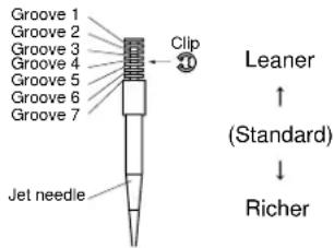 The clip position is the jet needle groove on which the clip is installed.The positions are numbered from the top.Check that the accelerator pump operates smoothly. (except for rich mixture symptom). The clip position is the jet needle groove on which the clip is installed.The positions are numbered from the top.Check that the accelerator pump operates smoothly. (except for rich mixture symptom). | |
| Rich mixture Raise jet needle clip position. (1 groove up) | ||
| 1/4-3/4 throttleHard breathingLack of speed | Lower jet needle clip position. (1 groove down) | |
| 1/4-1/2 throttleSlow speed pick-upPoor acceleration | Raise jet needle clip position. (1 groove up) | |
| Closed to 1/4 throttleHard breathingSpeed down | Use jet needle with a smaller diameter. Slow-speed-circuit passageClogged → Clean.Overflow from carburetor | |
| Closed to 1/4 throttlePoor acceleration | Use jet needle with a larger diameter.Raise jet needle clip position. (1 groove up) | |
| Poor response in the low to intermediate speeds | Raise jet needle clip position.If this has no effect, lower the jet needle clip position. | |
| Poor response when throttle is opened quickly | Check overall settings.Use main jet with a lower calibration no.Raise jet needle clip position. (1 groove up)If these have no effect, use a main jet with a higher calibration no. and lower the jet needle clip position. | Check air filter for fouling.Check that the accelerator pump operates smoothly. |
TIP
This should be taken simply for an example. It is necessary to set the carburetor while checking the operating conditions of the engine.
CHASSIS SELECTION OF THE SECONDARY REDUCTION RATIO (SPROCKET)
| Secondary reduction ratio = Number of rear wheel sprocket teeth/Number of drive sprocket teeth |
| Standard secondary reduction ratio | 50/13(3.846)* 47/14(3.357) |
* For EUROPE
- It is generally said that the secondary gear ratio should be reduced for a longer straight portion of a speed course and should be increased for a course with many corners. Actually, however, as the speed depends on the ground condition of the day of the ride, be sure to run through the circuit to set the machine suitable for the entire course.
- In actuality, it is very difficult to achieve settings suitable for the entire course and some settings may be sacrificed. Thus, the settings should be matched to the portion of the course that has the greatest effect on the ride result. In such a case, run through the entire course while making notes of lap times to find the best balance; then, determine the secondary reduction ratio.
- If a course has a long straight portion where a machine can run at maximum speed, the machine is generally set such that it can develop its maximum revolutions toward the end of the straight line, with care taken to avoid the engine over-revving.
TIP
Riding technique varies from rider to rider and the performance of a machine also vary from machine to machine. Therefore, do not imitate other rider's settings from the beginning but choose your own setting according to the level of your riding technique.
DRIVE AND REAR WHEEL SPROCKETS SETTING PARTS
| Part name | Size Part number |
| Drivesprocket"1"(STD)** (STD) | 13T 9383B-13218* 14T 9383B-14222 |
| Rear wheel sprocket"2"* (STD) | ** 47T 1C3-25447-0048T 5GS-25448-50* 48T 1C3-25448-00* 49T 1C3-25449-00(STD)50T 5TJ-25450-80*(STD)* 50T 1C3-25450-00* 51T 1C3-25451-0052T 5TJ-25452-80* 52T 1C3-25452-00 |
* For AUS and NZ
** For EUROPE

text_image
Technical diagram of a mechanical gear assembly with labeled parts ① and ②TIRE PRESSURE
Tire pressure should be adjust to suit the road surface condition of the circuit.

Standard tire pressure: 100 kPa (1.0 kgf/cm ^2 , 15 psi)
- Under a rainy, muddy, sandy, or slippery condition, the tire pressure should be lower for a larger area of contact with the road surface.

Extent of adjustment: 60–80 kPa (0.6–0.8 kgf/cm ^2 , 9.0–12 psi)
- Under a stony or hard road condition, the tire pressure should be higher to prevent a flat tire.

Extent of adjustment: 100–120 kPa (1.0–1.2 kgf/cm ^2 , 15–18 psi)
FRONT FORK SETTING
The front fork setting should be made depending on the rider's feeling of an actual run and the circuit conditions. The front fork setting includes the following three factors:
- Setting of air spring characteristics
- Change the fork oil level.
- Setting of spring preload
- Change the spring.
• Install the adjustment washer.
- Setting of damping force
- Change the compression damping.
- Change the rebound damping. The spring acts on the load and the damping force acts on the cushion travel speed.
CHANGE IN LEVEL AND
CHARACTERISTICS OF FORK OIL Damping characteristic near the final stroke can be changed by changing the fork oil amount.
NOTICE
Adjust the oil level in 5 mm (0.2 in) increments or decrements. Too low oil level causes the front fork to produce a noise at full rebound or the rider to feel some pressure on his hands or body. Alternatively, too high oil level will develop unexpectedly early oil lock with the consequent shorter front fork travel and deteriorated performance and characteristics. Therefore, adjust the front fork within the specified range.

Standard oil level: 132 mm (5.20 in) Extent of adjustment: 95–150 mm (3.74–5.91 in) From top of outer tube with inner tube and damper rod fully compressed without spring.
A

line
| Label | Value | |---|---| | ① | Maximum | | ② | Medium | | ③ | Minimum |A. Air spring characteristics in relation to oil level change
B. Load
C. Stroke
1. Max. oil level
2. Standard oil level
3. Min. oil level
ADJUSTING THE SPRING PRELOAD
The spring preload is adjusted by installing the adjustment washer "1" between the fork spring "2" and damper rod "3".

text_image
① ② ③ T=2.3 mm (0.09 in)NOTICE
Do not install three or more adjustment washers for each front fork.
WARNING
Always adjust each front fork to the same setting. Uneven adjustment can cause poor handling and loss of stability.

Standard washer quantity:
Zero adjustment washers
Extent of adjustment: Zero-2 adjustment washers

text_image
A [kg (lb)] ① ② ③A. Load
B. Fork stroke
1. Without adjustment washer (standard)
2.1 adjustment washer
3. 2 adjustment washers
SETTING OF SPRING AFTER REPLACEMENT
As the front fork setting can be easily affected by rear suspension, take care so that the machine front and rear are balanced (in position, etc.) when setting the front fork.
-
Use of soft spring
-
Change the rebound damping. Turn out one or two clicks.
- Change the compression damping.
Turn in one or two clicks.
TIP
Generally a soft spring gives a soft riding feeling. Rebound damping tends to become stronger and the front fork may sink deeply over a series of gaps.
-
Use of stiff spring
-
Change the rebound damping. Turn in one or two clicks.
- Change the compression damping.
Turn out one or two clicks.
TIP
Generally a stiff spring gives a stiff riding feeling. Rebound damping tends to become weaker, resulting in lack of a sense of contact with the road surface or in a vibrating handlebar.
FRONT FORK SETTING PARTS
- Adjustment washer "1"
| TYPE (thickness) | PART NUMBER |
| T = 2.3 mm (0.09 in) | 5XE-23364-00 |
- Front fork spring "2"
| TYPE | SPRING RATE | SPRING PART NUMBER (-23141-) | I.D. MARK (slits) |
| SOFT | 0.408 0.418 0.428 0.438 | 5TJ-00 | 5TJ-10 || 5TJ-20 ||| 5TJ-30 ||| | |
| STD 0.449 5T | J-A0 — | ||
| STIFF | 0.459 0.469 | 5TJ-50 |-| 5TJ-60 |-|| | |
TIP
The I.D. mark (slits) "a" is proved on the end of the spring.
NOTICE
When using a spring with a spring rate of 0.469 kg/mm, do not install two or more adjustment washers for each front fork.

text_image
Exploded view diagram of a mechanical assembly with labeled parts and exploded viewREAR SUSPENSION SETTING
The rear suspension setting should be made depending on the rider's feeling of an actual run and the circuit conditions.
The rear suspension setting includes the following two factors:
-
Setting of spring preload
-
Change the set length of the spring.
-
Change the spring.
-
Setting of damping force
-
Change the rebound damping.
- Change the compression damping.
CHOOSING SET LENGTH
- Place a stand or block under the engine to put the rear wheel above the floor, and measure the length "a" between the rear wheel axle center and the rear fender holding bolt.

text_image
Technical diagram of a bicycle's front wheel and suspension system with labeled components and dimension annotation- Remove the stand or block from the engine and with a rider astride the seat, measure the sunken length "b" between the rear wheel axle center and the rear fender holding bolt.

natural_image
Technical line drawing of a motorcycle's front wheel and side gear assembly (no text or symbols)- Loosen the locknut "1" and make adjustment by turning the spring adjuster "2" to achieve the standard figure from the subtraction of the length "b" from the length "a".

Standard figure: 90–100 mm (3.5–3.9 in)
TIP
- If the machine is new and after it is broken in, the same set length of the spring may change because of the initial fatigue, etc. of the spring. Therefore, be sure to make reevaluation.
- If the standard figure cannot be achieved by adjusting the spring adjuster and changing the spring set length, replace the spring with an optional one and make re-adjustment.

text_image
Technical diagram showing mechanical assembly with labeled parts ① and ②, likely illustrating a valve or spring mechanism.SETTING OF SPRING AFTER REPLACEMENT
After replacement, be sure to adjust the spring to the set length [sunken length 90–100 mm (3.5–3.9 in)] and set it.
-
Use of soft spring
-
Set the soft spring for less re-bound damping to compensate for its less spring load. Run with the rebound damping adjuster one or two clicks on the softer side and readjust it to suit your preference.
- Use of stiff spring
- Set the soft spring for more re-bound damping to compensate for its greater spring load. Run with the rebound damping adjuster one or two clicks on the stiffer side and readjust it to suit your preference.
TIP
Adjusting the rebound damping will be followed more or less by a change in the compression damping. For correction, turn the low compression damping adjuster on the softer side.
NOTICE
When using a rear shock absorber other than currently installed, use the one whose overall length "a" does not exceed the standard as it may result in faulty performance. Never use one whose overall length is greater than standard.

Length "a" of standard shock: 488.5 mm (19.23 in)

natural_image
Technical line drawing of a mechanical spring assembly with no text or symbolsREAR SHOCK ABSORBER SETTING PARTS
- Rear shock spring "1"
| TYPE | SPRING RATE | SPRING PART NUM-BER (-22212-) | I.D. MARK/Q'TY |
| SOFT | 4.3 5UN | -00 Brown/1 | |
| 4.5 5 | UN-10 Green/1 | ||
| 4.7 5 | UN-20 Red/1 | ||
| 4.9 5 | UN-30 Black/1 | ||
| 5.1 5 | UN-40 Blue/1 | ||
| STD | 5.3 5UN | -50 Yellow/1 | |
| 5.5 5 | UN-60 Pink/1 | ||
| STIFF | 5.7 5UN | -70 White/1 |
TIP
- The I.D. mark "a" is marked at the end of the spring.
- Spring specification varies according to the color and quantity of I.D. marks.

text_image
Technical diagram of a mechanical spring assembly with labeled parts ① and ②- Extent of adjustment (spring preload)
| SPRING PART NUMBER(-22212-) | Maximum | Minimum |
| 5UN-005UN-105UN-205UN-30 | Position in which the spring is turned in 20 mm (0.79 in) from its free length. | Position in which the spring is turned in 1.5 mm (0.06 in) from its free length. |
| 5UN-405UN-505UN-605UN-70 | Position in which the spring is turned in 22 mm (0.87 in) from its free length. |
TIP
For the spring preload adjustment, refer to "ADJUSTING THE REAR SHOCK ABSORBER SPRING PRE-LOAD" in the CHAPTER 3.
SUSPENSION SETTING (FRONT FORK)
TIP
- If any of the following symptoms is experienced with the standard position as the base, make resetting by reference to the adjustment procedure given in the same chart.
- Before any change, set the rear shock absorber sunken length to the standard figure 90–100 mm (3.5–3.9 in).
| Symptom | Section | Check Adjust | ||||
| Jump | Large gap | Medium gap | Small gap | |||
| Stiff over entire range | ○ | ○ | ○ | Compression damping Turn adjuster counterclockwise (about 2 clicks) to decrease damping.Oil level (oil amount) Decrease oil level by about 5–10 mm (0.2–0.4 in).Spring Replace with soft spring. | ||
| Unsmooth movement over entire range | ○ | ○ | ○ | ○ | Outer tube Check for any Inner tubeUnder bracket tightening torque | bends, dents, and other noticeable scars, etc. If any, replace affected parts.Retighten to specified torque. |
| Poor initial movement | ○ | Rebound damping Turn adjuster counterclockwise (about 2 clicks) to decrease damping.Oil seal Apply grease in oil seal wall. | ||||
| Soft over entire range, bottoming out | ○ | ○ | Compression damping Turn adjuster clockwise (about 2 clicks) to increase damping.Oil level (oil amount) Increase oil level by about 5–10 mm (0.2–0.4 in).Spring Replace with stiff spring. | |||
| Stiff toward stroke end | ○ | Oil level | (oil amount) | Decrease oil level by about | 5 mm (0.2 in). | |
| Soft toward stroke end, bottoming out | ○ | Oil level | (oil amount) | Increase oil level by about | 5 mm (0.2 in). | |
| Stiff initial movement | ○ | ○ | ○ | ○ | Compression damping Turn adjuster counterclockwise (about 2 clicks) to decrease damping. | |
| Low front, tending to lower front posture | ○ | ○ | Compression damping Turn adjuster clockwise (about 2 clicks) to increase damping.Rebound damping Turn adjuster counterclockwise (about 2 clicks) to decrease damping.Balance with rear end Set sunken length for 95–100 mm (3.7–3.9 in) when one passenger is astride seat (lower rear posture).Oil level (oil amount) Increase oil level by about 5 mm (0.2 in). | |||
| "Obtrusive" front, tending to upper front posture | ○ | ○ | Compression damping Turn adjuster counterclockwise (about 2 clicks) to decrease damping.Balance with rear end Set sunken length for 90–95 mm (3.5–3.7 in) when one passenger is astride seat (upper rear posture).Spring Replace with soft spring.Oil level (oil amount) Decrease oil level by about 5–10 mm (0.2–0.4 in). | |||
SUSPENSION SETTING (REAR SHOCK ABSORBER)
TIP
- If any of the following symptoms is experienced with the standard position as the base, make resetting by reference to the adjustment procedure given in the same chart.
- Adjust the rebound damping in 2-click increments or decrements.
- Adjust the low compression damping in 1-click increments or decrements.
- Adjust the high compression damping in 1/6 turn increments or decrements.
| Symptom | Section | Check Adjust | ||||
| Jump | Large gap | Medium gap | Small gap | |||
| Stiff, tending to sink | ○ | ○ | Rebound damping Turn adjuster counterclockwise (about 2 clicks) to decrease damping.Spring set length Set sunken length for 90–100 mm (3.5–3.9 in) when one passenger is astride seat. | |||
| Spongy and unstable | ○ | ○ | Rebound damping Turn adjuster clockwise (about 2 clicks) to increase damping.Low compression dampingTurn adjuster clockwise (about 1 click) to increase damping.Spring Replace with stiff spring. | |||
| Heavy and dragging | ○ | ○ | Rebound damping Turn adjuster counterclockwise (about 2 clicks) to decrease damping.Spring Replace with soft spring. | |||
| Poor road gripping | ○ | Rebound damping Turn adjuster counterclockwise (about 2 clicks) to decrease damping.Low compression dampingTurn adjuster clockwise (about 1 clicks) to increase damping.High compression dampingTurn adjuster clockwise (about 1/6 turn) to increase damping.Spring set length Set sunken length for 90–100 mm (3.5–3.9 in) when one passenger is astride seat.Spring Replace with soft spring. | ||||
| Bottoming out | ○ | High compression dampingTurn adjuster clockwise (about 1/6 turn) to increase damping.Spring set length Set sunken length for 90–100 mm (3.5–3.9 in) when one passenger in astride seat.Spring Replace with stiff spring. | ||||
| Bouncing | ○ | Rebound damping Turn adjuster clockwise (about 2 clicks) to increase damping.Spring Replace with soft spring. | ||||
| Stiff travel | ○ | High compression dampingTurn adjuster counterclockwise (about 1/6 turn) to decrease damping.Spring set length Set sunken length for 90–100 mm (3.5–3.9 in) when one passenger is astride seat.Spring Replace with soft spring. | ||||
ENGINE
TIP
This section is intended for those who have basic knowledge and skill concerning the servicing of Yamaha motorcycles (e.g., Yamaha dealers, service engineers, etc.) Those who have little knowledge and skill concerning servicing are requested not to undertake inspection, adjustment, disassembly, or reassembly only by reference to this manual. It may lead to servicing trouble and mechanical damage.
RADIATOR
REMOVING THE RADIATOR
| Order Part name Q'ty Remarks | ||
| Drain the coolant. | Refer to "CHECKING THE COOLANT" sec- tion in the CHAPTER 3. | |
| Seat, fuel tank and left side cover | Refer to "REMOVING THE SEAT, FUEL TANK AND SIDE COVERS" section in the CHAPTER 3. | |
| 1 Radiator guard 2 | ||
| 2 Radiator hose clamp 10 Only loosening. | ||
| 3 Radiator hose 1 1 | ||
| 4 Left radiator 1 | ||
| 5 Radiator hose 3 1 | ||
| 6 Radiator pipe 2 1 | ||
| 7 Radiator hose 5 1 |

other
| Component | Dimension (m) | |-----------|---------------| | 1 | 16 | | 2 | 7 | | 3 | 10 | | 4 | 10 | | 5 | 16 | | 6 | 7 | | 7 | 10 | | 8 | 16 | | 9 | 7 | | 10 | 10 | | 11 | 16 | | 12 | 7 | | 13 | 10 | | 14 | 16 | | New | 2 | | Other | Not labeled |HANDLING NOTE
WARNING
Do not remove the radiator cap when the engine and radiator are hot. Scalding hot fluid and steam may be blown out under pressure, which could cause serious injury. When the engine has cooled, open the radiator cap by the following procedure:
Place a thick rag, like a towel, over the radiator cap, slowly rotate the cap counterclockwise to the detent. This procedure allows any residual pressure to escape. When the hissing sound has stopped, press down on the cap while turning counterclockwise and remove it.
CHECKING THE RADIATOR
- Inspect:
- Radiator core "1"
Obstruction → Blow out with compressed air through rear of the radiator.
Bent fin → Repair/replace.

text_image
Diagram illustrating a mechanical or structural assembly with labeled component ①, showing internal layers and a magnified inset.INSTALLING THE RADIATOR
-
Install:
-
O-ring "1" New
- Radiator pipe 1 "2"
- Bolt (radiator pipe) "3"

Bolt (radiator pipe): 10 Nm (1.0 m·kg, 7.2 ft·lb)
TIP
Apply the lithium soap base grease on the O-ring.

text_image
① New ② ③-
Install:
-
Catch tank hose "1"
- Radiator hose 2 "2"
- Radiator hose 3 "3"
- Radiator pipe 2 "4"
- Radiator hose 5 "5"
- Radiator hose 4 "6" To right radiator "7".

text_image
Labeled diagram of a heat exchanger or radiator system with numbered components-
Install:
-
Right radiator "1"
- Bolt (right radiator) "2"

Bolt (right radiator): 10 Nm (1.0 m·kg, 7.2 ft·lb)
- Radiator hose 5 "3" Refer to "CABLE ROUTING DIAGRAM" section in the CHAPTER 2.

text_image
Technical diagram of a mechanical assembly with numbered components and labeled parts-
Install:
-
Left radiator "1"
- Bolt (left radiator) "2"

Bolt (left radiator): 10 Nm (1.0 m·kg, 7.2 ft·lb)
- Radiator hose 1 "3"

Radiator hose 1: 2 Nm (0.2 m·kg, 1.4 ft·lb)
Refer to "CABLE ROUTING DIAGRAM" section in the CHAPTER 2.
- Tighten:
- Radiator hose clamp "4"

Radiator hose clamp: 2 Nm (0.2 m·kg, 1.4 ft·lb)

text_image
Technical diagram showing mechanical assembly with numbered components and labeled parts- Install:
- Radiator guard "1"
TIP
First fit the inner hook portion "a" and then the outer one "b" onto the radiator.

text_image
Technical diagram showing mechanical assembly with labeled parts (a, b) and directional arrows indicating movement or force.-
Install:
-
Catch tank "1"
- Bolt (catch tank) "2"

Bolt (catch tank): 7 Nm (0.7 m·kg, 5.1 ft·lb)
- Bolt (catch tank) "3"

Bolt (catch tank): 16 Nm (1.6 m·kg, 11 ft·lb)
- Catch tank hose "4"
- Catch tank breather hose "5" Refer to "CABLE ROUTING DIAGRAM" section in the CHAPTER 2.

text_image
Technical diagram of a mechanical assembly with numbered components and directional indicatorsCARBURETOR
REMOVING THE CARBURETOR

DISASSEMBLING THE CARBURETOR

text_image
Exploded view diagram of a mechanical assembly with numbered parts for identification| Order Part name Q'ty Remarks | ||
| 19 Main jet 1 | ||
| 20 Needle jet 1 | ||
| 21 Spacer 1 | ||
| 22 Pilot jet 1 | ||
| 23 Starter jet 1 | ||
| 24 Push rod 1 Pull the push rod. | ||
| 25 Throttle shaft assembly 1 | ||
| 26 Push rod link lever assembly 1 | ||
| 27 Main air jet 1 | ||
| 28 Pilot air jet 1 | ||
| 29 Cold starter plunger 1 |
HANDLING NOTE
NOTICE
Do not loosen the screw (throttle position sensor) "1" except when changing the throttle position sensor due to failure because it will cause a drop in engine performance.

natural_image
Mechanical assembly diagram showing a lever and linkage mechanism (no text or labels)REMOVING THE PILOT SCREW (For EUROPE)
- Remove:
- Pilot screw "1"
TIP
To optimize the fuel flow at a small throttle opening, each machine's pilot screw has been individually set at the factory. Before removing the pilot screw, turn it in fully and count the number of turns. Record this number as the factory-set number of turns out.

natural_image
Technical line drawing of a mechanical component with no visible text or symbolsCHECKING THE CARBURETOR
- Inspect:
- Carburetor body Contamination → Clean.
TIP
- Use a petroleum based solvent for cleaning. Blow out all passages and jets with compressed air.
- Never use a wire.

natural_image
Line drawing of a hand using a tool to adjust or install a mechanical component (no text or symbols present)2. Inspect:
- Main jet "1"
- Pilot jet "2"
- Needle jet "3"
- Starter jet "4"
• Pilot air jet "5" - Leak jet "6"
- Main air jet "7"
Damage → Replace. Contamination → Clean.
TIP
- Use a petroleum based solvent for cleaning. Blow out all passages and jets with compressed air.
- Never use a wire.

text_image
Diagram showing seven labeled mechanical components with numbered parts, likely illustrating a series of plug or connector packages.CHECKING THE NEEDLE VALVE
-
Inspect:
-
Needle valve "1"
- Valve seat "2"
Grooved wear "a" → Replace. Dust "b" → Clean. - Filter "c" Clogged → Clean.

text_image
Technical diagram showing two mechanical components labeled a, b, and c with numbered parts and cross-sectional views.CHECKING THE THROTTLE VALVE
- Check:
- Free movement Stick → Repair or replace.
TIP
Insert the throttle valve "1" into the carburetor body, and check for free movement.

text_image
Technical diagram showing mechanical assembly with labeled component and directional arrowCHECKING THE JET NEEDLE
- Inspect:
- Jet needle "1" Bends/wear → Replace.
- Clip groove Free play exists/wear → Replace.

MEASURING AND ADJUSTING THE FLOAT HEIGHT
- Measure:
- Float height "a" Out of specification → Adjust.

Float height: 8.0 mm (0.31 in)

natural_image
Technical line drawing of a mechanical assembly with no visible text or symbols[Non-Text]
Measurement and adjustment steps:
a. Hold the carburetor in an upside down position.
TIP
- Slowly tilt the carburetor in the opposite direction, then take the measurement when the needle valve aligns with the float arm.
- If the carburetor is level, the weight of the float will push in the needle valve, resulting in an incorrect measurement.
b. Measure the distance between the mating surface of the float chamber and top of the float using a vernier calipers.
TIP
The float arm should be resting on the needle valve, but not compressing the needle valve.
c. If the float height is not within specification, inspect the valve seat and needle valve.
d. If either is worn, replace them both.
e. If both are fine, adjust the float height by bending the float tab "b" on the float.

f. Recheck the float height.

CHECKING THE FLOAT
- Inspect:
- Float "1" Damage → Replace.

CHECKING THE STARTER PLUNGER
- Inspect:
- Cold starter plunger "1" - Hot starter plunger "2" Wear/damage → Replace.

text_image
Technical diagram of two types of electrical connectors with labeled parts ① and ②CHECKING THE ACCELERATOR PUMP
- Inspect:
- Diaphragm (accelerator pump) "1" - Spring (accelerator pump) "2" - Accelerator pump cover "3" - O-ring "4" - Push rod "5" Tears (diaphragm)/damage→Replace. Dirt → Clean.

text_image
Exploded view diagram of a mechanical component with numbered parts for identification- Inspect:
- Throttle shaft "1" - Spring "2" - Lever 1 "3" - Spring 1 "4" - Lever 2 "5" - Spring 2 "6" Dirt → Clean.

text_image
Exploded view diagram of a mechanical assembly with numbered parts for identificationCHECKING THE AIR CUT VALVE
- Inspect:
- Diaphragm (air cut valve) "1" - Spring (air cut valve) "2" - Air cut valve cover "3" - O-ring "4" Tears (diaphragm)/damage → Replace.

text_image
Technical diagram showing four labeled mechanical components: coiled spring, spring, and clamping mechanism.ASSEMBLING THE CARBURETOR
- Install:
• Cold starter plunger
- Install:
- Pilot air jet "1" - Main air jet "2"

text_image
Technical diagram of a mechanical component with numbered parts labeled ① and ②- Install:
- Spring 1 "1" - Lever 1 "2" To lever 2 "3".
TIP
Make sure the spring 1 fits on the stopper "a" of the lever 2.

text_image
Technical diagram of a mechanical component with numbered parts labeled 1, 2, 3, and a central spring-like structure.- Install:
• Spring 2 "1" To lever 2 "2".

- Install:
- Push rod link lever assembly "1"
TIP
Make sure the stopper "a" of the spring 2 fits into the recess "b" in the carburetor.

text_image
Technical diagram of automotive suspension system components with labeled parts (a, b, 1) and numbered parts- Install:
- Washer "1" - Circlip "2"

natural_image
Technical line drawing of a mechanical assembly with no visible text or symbols- Install:
- Spring "1" To throttle shaft "2".
TIP
Install the bigger hook "a" of the spring fits on the stopper "b" of the throttle shaft pulley.

text_image
Technical diagram of a mechanical spring assembly with labeled parts (a, b, ①, ②)- Install:
- Throttle shaft assembly "1" - Washer (metal) "2" - Washer (resin) "3" - Valve lever "4"
TIP
- Apply the fluorochemical grease on the bearings.
- Fit the projection "a" on the throttle shaft assembly into the slot "b" in the throttle position sensor.
- Make sure the stopper "c" of the spring fits into the recess in the carburetor.
- Turn the throttle shaft assembly left while holding down the lever 1 "5" and fit the throttle stop screw tip "d" to the stopper "e" of the throttle shaft assembly pulley.

text_image
Technical diagram showing a mechanical assembly with numbered components and a magnified inset view labeled a, b, c.
natural_image
Line drawing of a mechanical assembly with hands operating a component (no text or symbols visible)
text_image
Technical diagram of a mechanical assembly with numbered components and directional arrows indicating motion or movement.9. Install:
- Push rod "1"
TIP
While holding down the lever 1 "2", insert the push rod farthest into the carburetor.

text_image
Technical diagram showing mechanical assembly with numbered components, likely for assembly or maintenance instructions.10. Install:
- Starter jet "1"
- Pilot jet "2"
- Spacer "3"
- Needle jet "4"
- Main jet "5"

text_image
Technical diagram of a mechanical assembly with numbered components for identification11. Install:
- Needle valve "1"
- Float "2"
- Float pin "3"
TIP
• After installing the needle valve to the float, install them to the carburetor.
- Check the float for smooth movement.

text_image
Technical diagram of a mechanical assembly with numbered components labeled ①, ②, and ③.12. Install: (For EUROPE)
- Pilot screw "1"
- Spring "2"
- Washer "3"
- O-ring "4"

text_image
Technical diagram of a mechanical assembly with numbered components for identification
Note the following installation points:
a. Turn in the pilot screw until it is lightly seated.
b. Turn out the pilot screw by the number of turns recorded before removing.

Pilot screw (example): 2 turns out
13. Install:
• O-ring
- Leak jet "1"
- Float chamber "2"
• Bolt (float chamber) "3"
- Cable holder (throttle stop screw cable) "4"
- Hose holder (carburetor breather hose) "5"

text_image
Technical diagram of a mechanical assembly with numbered components for identification14. Install:
• Diaphragm (air cut valve) "1"
- Spring (air cut valve) "2"
- O-ring "3"
• Air cut valve cover "4"
- Holder (cylinder head breather hose) "5"
- Screw (air cut valve cover) "6"

text_image
Technical diagram of a mechanical assembly with numbered components for identification15. Install:
• Diaphragm (accelerator pump)
"1"
- Spring "2"
- O-ring "3"
- Accelerator pump cover "4"
- Hose holder (drain hose) "5"
- Screw (accelerator pump cover) "6"
TIP
Install the diaphragm (accelerator pump) with its mark "a" facing the spring.

text_image
Technical diagram of a mechanical assembly with numbered components for identification16. Install:
- Jet needle "1"
• Collar "2" - Spring "3"
- Needle holder "4"
- Throttle valve plate "5" To throttle valve "6".

text_image
Technical diagram of a mechanical device with numbered components for identification17. Install:
- Throttle valve assembly "1"
- Screw (throttle shaft) "2"

TIP
Install the valve lever rollers "3" into the slits "a" of the throttle valve.


natural_image
Pure mechanical assembly diagram without any text, numbers, or symbols18. Install:
- O-ring "1"
- Valve lever housing cover "2"
- Bolt (valve lever housing cover) "3"

text_image
Technical diagram of a mechanical valve or pump assembly with numbered components19. Install:
• Carburetor breather hose "1"
TIP
Install the carburetor breather hoses to the carburetor so that the hoses do not bend near where they are installed.

text_image
Technical diagram of a mechanical assembly with labeled parts, showing components like '①' and '②'ADJUSTING THE ACCELERATOR PUMP TIMING
Adjustment steps:
TIP
In order for the throttle valve height "a" to achieve the specified value, tuck under the throttle valve plate "1" the rod "2" etc. with the same outer diameter as the specified value.

Throttle valve height: 0.8 mm (0.031 in)

text_image
Technical diagram of a mechanical component with labeled parts and an inset showing a circular feature with dimension 'a'.a. Fully turn in the accelerator pump adjusting screw "3".
b. Check that the link lever "4" has free play "b" by pushing lightly on it.

text_image
Technical diagram of a mechanical device with labeled parts, including gears and springsc. Gradually turn out the adjusting screw while moving the link lever until it has no more free play.

INSTALLING THE CARBURETOR
- Install:
- Carburetor joint "1"

Carburetor joint:
10 Nm (1.0 m·kg, 7.2 ft·lb)

natural_image
Technical line drawing of a mechanical assembly with labeled component (no readable text or symbols)2. Install:
- Carburetor "1"
TIP
Install the projection "a" between the carburetor joint slots.

text_image
Technical diagram of a mechanical assembly with labeled parts, including numbered annotations (①, ②, ③) and component callouts.3. Install:
• Hot starter plunger "1"

Hot starter plunger: 2 Nm (0.2 m·kg, 1.4 ft·lb)

natural_image
Technical line drawing of a mechanical assembly with pipes and components (no text or symbols)4. Tighten:
- Bolt (carburetor joint) "1"

Bolt (carburetor joint): 3 Nm (0.3 m·kg, 2.2 ft·lb)
- Bolt (air filter joint) "2"

Bolt (air filter joint): 3 Nm (0.3 m·kg, 2.2 ft·lb)

text_image
Technical diagram of a mechanical assembly with numbered components, likely for assembly or maintenance instructions.5. Install:
- Throttle cable (return) "2"

Throttle cable (return): 11 Nm (1.1 m·kg, 8.0 ft·lb)

text_image
Technical diagram of a mechanical assembly with numbered components, likely for assembly or maintenance instructions.6. Adjust:
- Throttle grip free play Refer to "ADJUSTING THE THROTTLE CABLE FREE PLAY" section in the CHAPTER 3.
7. Install:
- Throttle cable cover "1" - Bolt (throttle cable cover) "2"

Bolt (throttle cable cover): 4 Nm (0.4 m·kg, 2.9 ft·lb)

text_image
Technical diagram showing mechanical assembly with numbered components and labeled parts8. Install:
- Throttle position sensor lead coupler "1" - Clamp "2" Refer to "CABLE ROUTING DIAGRAM" section in the CHAPTER 2.

text_image
Technical diagram of a mechanical assembly with numbered components, likely for assembly or maintenance instructions.9. Install:
- Clamp "1" Refer to "CABLE ROUTING DIAGRAM" section in the CHAPTER 2.

natural_image
Technical line drawing of a mechanical assembly with no visible text or symbolsAIR INDICTION SYSTEM
REMOVING THE AIR INDUCTION SYSTEM

text_image
7 Nm (0.7 m · kg, 5.1 ft · lb) 10 Nm (1.0 m · kg, 7.2 ft · lb) 4 Nm (0.4 m · kg, 2.9 ft · lb) Order Part name Q'ty Remarks 1 Bracket 1 2 Air cut-off valve assembly 1 3 Air induction hose (air cut-off valve - front of cylinder head) 4 Air induction pipe 1 5 Gasket 1 6 Air induction hose (air cut-off valve - rear of cylinder head) 7 Air induction hose (air cut-off valve - air filter case)CHECKING THE AIR INDUCTION SYSTEM
1. Inspect:
• Air induction hose
Crack/damage → Replace.
• Air induction pipe
Crack/damage → Replace.
2. Check:
- Operation of air cut valve Pass air through the pipe and check the air cut valve for operation. Does not meet the following condition → Replace the air cut valve assembly.
| "a" to "b" | Air passes. |
| "b" to "a" | Air does not pass. |
| "a" to "b" | Air does not pass when specified pressure is on "c". |
TIP
- Blow in air to check for operation.
- When using vacuum, check by the use of the vacuum/pressure pump gauge set "1".
| Vacuum/pressure pump gauge set:YB-35956-A/90890-06756 | |
 | Vacuum specifying pressure:46.7–86.7 kPa (350–650 mmHg, 13.8–25.6 inHg) |
NOTICE
When using vacuum on the pipe "c", take care not to exceed the specified value.
A

B


text_image
C a b c ①a. From air filter
b. To cylinder head (exhaust port)
c. From cylinder head (intake port)
A. Check for induction from air filter.
B. Check for prevention of backflow into air filter.
C. Check for prevention of afterburn. (When throttle is closed at sudden deceleration)
CAMSHAFTS
REMOVING THE CYLINDER HEAD COVER


text_image
13 Nm (1.3 m · kg, 9.4 ft · lb) 10 Nm (1.0 m · kg, 7.2 ft · lb)| Order Part name Q'ty Remarks | |||
| Seat and fuel tank | Refer to "REMOVING THE SEAT, FUEL TANK AND SIDE COVERS" section in the CHAPTER 3. | ||
| Air cut-off valve assembly Refer to "AIR INDUCTION SYSTEM" section. | |||
| 1 Spark plug 1 | |||
| 2 Cylinder head breather hose 1 | |||
| 3 Bolt (cylinder head cover) 2 | |||
| 4 Cylinder head cover 1 | |||
| 5 Cylinder head cover gasket 1 | |||
| 6 Timing chain guide (top side) 1 | |||
REMOVING THE CAMSHAFTS

text_image
10 Nm (1.0 m · kg, 7.2 ft · lb) 10 Nm (1.0 m · kg, 7.2 ft · lb) 7 Nm (0.7 m · kg, 5.1 ft · lb) New New E M 5 6 8 3 4 1 2 B New| Order Part name Q'ty Remarks | ||
| 1 Timing mark accessing screw 1 Refer to removal section. | ||
| 2 Crankshaft end accessing screw 1 Refer to removal section. | ||
| 3 Timing chain tensioner cap bolt 1 Refer to removal section. | ||
| 4 Timing chain tensioner 1 Refer to removal section. | ||
| 5 Camshaft cap 2 Refer to removal section. | ||
| 6 Clip 2 Refer to removal section. | ||
| 7 Exhaust camshaft 1 Refer to removal section. | ||
| 8 Intake camshaft 1 Refer to removal section. |
REMOVING THE CAMSHAFT
-
Remove:
-
Timing mark accessing screw "1"
- Crankshaft end accessing screw "2"

natural_image
Mechanical assembly diagram showing gear and components (no text or labels)- Align:
• T.D.C. mark
With align mark.
Checking steps:
a. Turn the crankshaft counterclockwise with a wrench.
b. Align the T.D.C. mark "a" on the rotor with the align mark "b" on the crankcase cover when piston is at T.D.C. on compression stroke.
TIP
In order to be sure that the piston is at Top Dead Center, the punch mark "c" on the exhaust camshaft and the punch mark "d" on the intake camshaft must align with the cylinder head surface, as shown in the illustration.

text_image
Technical diagram of a mechanical assembly with labeled parts and directional arrow indicating motion or force
natural_image
Technical line drawing of a mechanical gear assembly with no visible text or symbols
-
Remove:
-
Timing chain tensioner cap bolt "1"
• Timing chain tensioner "2"
• Gasket

text_image
Technical diagram of a mechanical component with numbered parts labeled ① and ②-
Remove:
-
Bolt (camshaft cap) "1"
- Camshaft cap "2"
- Clip
TIP
Remove the bolts (camshaft cap) in a crisscross pattern, working from the outside in.
NOTICE
The bolts (camshaft cap) must be removed evenly to prevent damage to the cylinder head, camshafts or camshaft caps.

text_image
Technical diagram of an engine cylinder assembly with numbered components and labeled parts-
Remove:
-
Exhaust camshaft "1"
- Intake camshaft "2"
TIP
Attach a wire "3" to the timing chain to prevent it from falling into the crank-case.

text_image
Technical diagram of an engine cylinder head with labeled components and structural detailsCHECKING THE CAMSHAFT
- Inspect:
- Cam lobe Pitting/scratches/blue discoloration → Replace.
- Measure:
- Cam lobe length "a" and "b" Out of specification → Replace.

Cam lobes length:
Intake "a":
29.65–29.75 mm
(1.1673-1.1713 in)
29.55 mm (1.1634 in)
Intake "b":
22.45–22.55 mm
(0.8839–0.8878 in)
22.35 mm (0.8799 in)
Exhaust "a":
30.399–30.499 mm
(1.1968–1.2007 in)
30.299 mm (1.1929 in)
Exhaust "b":
22.45–22.55 mm
(0.8839–0.8878 in)
22.35 mm (0.8799 in)

text_image
Diagram showing a hand using a micrometer to measure a small object, with labeled measurement 'a' indicating the step.11151001

natural_image
Line drawing of a hand using a measuring tool to measure a component (no text or symbols present)11151002
- Measure:
- Runout (camshaft)
Out of specification → Replace.

Runout (camshaft):
Less than 0.03 mm (0.0012 in)

natural_image
Pure mechanical diagram of a valve or pump assembly without any text, labels, or symbols115482
4. Measure:
- Camshaft-to-cap clearance Out of specification → Measure camshaft outside diameter.

Camshaft-to-cap clearance:
0.028–0.062 mm
(0.0011–0.0024 in)

Measurement steps:
a. Install the camshaft onto the cylinder head.
b. Position a strip of Plastigauge ^® "1" onto the camshaft.

text_image
Technical diagram of a mechanical component with numbered parts, likely for assembly or labeling.c. Install the clip, dowel pins and camshaft caps.

Bolt (camshaft cap): 10 Nm (1.0 m·kg, 7.2 ft·lb)
TIP
- Tighten the bolts (camshaft cap) in a crisscross pattern from innermost to outer caps.
- Do not turn the camshaft when measuring clearance with the Plastigauge®.
d. Remove the camshaft caps and measure the width of the Plastigauge ^® "1".

text_image
Technical diagram showing mechanical assembly with numbered components and directional arrows
5. Measure:
- Camshaft outside diameter "a" Out of specification→Replace the camshaft. Within specification → Replace camshaft case and camshaft caps as a set.

Camshaft outside diameter:
21.959–21.972 mm (0.8645–0.8650 in)

natural_image
Illustration of hands using a mechanical tool to measure a cylindrical component (no text or symbols present)CHECKING THE CAMSHAFT SPROCKET
1. Inspect:
- Camshaft sprocket "1" Wear/damage → Replace the camshaft assembly and timing chain as a set.

natural_image
Technical line drawing of a mechanical gear assembly with no visible text or symbols- Decompression system

Checking steps:
a. Check that the decompression mechanism cam "1" moves smoothly. b. Check that the decompression mechanism cam lever pin "2" projects from the camshaft.

text_image
Technical diagram of a mechanical gear assembly with labeled parts ① and ②
CHECKING THE TIMING CHAIN TENSIONER
1. Check:
- While pressing the tensioner rod lightly with fingers, use a thin screwdriver "1" and wind the tensioner rod up fully clockwise.
- When releasing the screwdriver by pressing lightly with fingers, make sure that the tensioner rod will come out smoothly.
- If not, replace the tensioner assembly.

natural_image
Illustration of a hand holding a mechanical component with a tool, showing motion direction (no text or symbols)
natural_image
Line drawing of a hand holding a tool, no text or symbols presentINSTALLING THE CAMSHAFT
1. Install:
- Exhaust camshaft "1"
- Intake camshaft "2"

text_image
Technical diagram of a mechanical assembly with labeled parts (①, ②, E) and components like gears and springs.
Installation steps:
a. Turn the crankshaft counterclockwise with a wrench.
TIP
- Apply the molybdenum disulfide oil on the camshafts.
- Apply the engine oil on the decompression system.
- Squeezing the decompression lever allows the crankshaft to be turned easily.
b. Align the T.D.C. mark "a" on the rotor with the align mark "b" on the crankcase cover when piston is at T.D.C. on compression stroke.

text_image
Technical diagram of a mechanical assembly with labeled parts and directional arrow indicating motion or forcec. Fit the timing chain "3" onto both camshaft sprockets and install the camshafts on the cylinder head.
TIP
The camshafts should be installed onto the cylinder head so that the punch mark "c" on the exhaust camshaft and the punch mark "d" on the intake camshaft must align with the cylinder head surface, as shown in the illustration.

text_image
Technical diagram of a mechanical gear assembly with labeled components (c, 3, d)NOTICE
Do not turn the crankshaft during the camshaft installation. Damage or improper valve timing will result.
d. Install the clips, camshaft caps "4" and bolts (camshaft cap) "5".

Bolt (camshaft cap): 10 Nm (1.0 m·kg, 7.2 ft·lb)

text_image
Technical diagram of a mechanical assembly with numbered components and a labeled motor (M) connection.TIP
- Before installing the clips, cover the cylinder head with a clean rag to prevent the clips from into the cylinder head cavity.
- Apply the molybdenum disulfide oil on the thread of the bolts (camshaft cap).
- Tighten the bolts to the specified torque in two or three steps in the proper tightening sequence as shown.
NOTICE
The bolts (camshaft cap) must be tightened evenly, or damage to the cylinder head, camshaft caps, and camshaft will result.
2. Install:
- Timing chain tensioner
▼▼▼▼▼▼▼▼▼▼▼▼▼▼▼▼▼▼▼▼▼▼▼▼▼▼▼▼▼▼▼▼▼▼▼▼▼▼▼▼▼▼▼▼▼▼▼▼▼▼▼▼▼▼▼▼▼▼▼▼▼▼▼▼▼▼▼▼▼▼▼▼▼▼▼▼▼▼▼▼▼▼▼▼▼▼▼▼▼▼▼▼▼▼▼▼▼▼▼▼▲
Installation steps:
a. While pressing the tensioner rod lightly with fingers, use a thin screwdriver and wind the tensioner rod up fully clockwise.

natural_image
Illustration of a hand holding a mechanical component with a tool, no text or symbols presentb. With the rod fully wound and the chain tensioner UP mark "a" facing upward, install the gasket "1" and the timing chain tensioner "2", and tighten the bolt "3" to the specified torque.

Bolt (timing chain tensioner): 10 Nm (1.0 m·kg, 7.2 ft·lb)

text_image
New ① ② ③ ④ ⑤c. Release the screwdriver, check the tensioner rod to come out and tighten the gasket "4" and the cap bolt "5" to the specified torque.

Tensioner cap bolt: 7 Nm (0.7 m·kg, 5.1 ft·lb)

text_image
New 4 5▲▲▲▲▲▲▲▲▲▲▲▲▲▲▲▲▲
3. Turn:
- Crankshaft Counterclockwise several turns.
4. Check:
- Rotor T.D.C. mark Align with the crankcase align mark.
- Camshaft match marks Align with the cylinder head surface.
Out of alignment → Adjust.
5. Install:
- Timing mark accessing screw "1"
- Crankshaft end accessing screw "2"

natural_image
Technical line drawing of a mechanical assembly with numbered components (no text or symbols)6. Install:
- Timing chain guide (top side) "1"
• Cylinder head cover gasket "2" - Cylinder head cover "3"
- Bolt (cylinder head cover) "4"

Bolt (cylinder head cover): 10 Nm (1.0 m·kg, 7.2 ft·lb)
TIP
Apply the sealant on the cylinder head cover gasket.

YAMAHA Bond No. 1215 (ThreeBond® No. 1215): 90890-85505

text_image
Technical diagram showing exploded view of a mechanical assembly with numbered components
natural_image
Technical line drawing of a mechanical component with no visible text or symbols7. Install:
• Cylinder head breather hose
- Spark plug

Spark plug: 13 Nm (1.3 m·kg, 9.4 ft·lb)
CYLINDER HEAD
REMOVING THE CYLINDER HEAD


text_image
38 Nm (3.8 m · kg, 27 ft · lb) 10 Nm (1.0 m · kg, 7.2 ft · lb) New 1 B 1 6 4 5 4 5 20 Nm (2.0 m · kg, 14 ft · lb) 18 Nm (1.8 m · kg, 13 ft · lb) New New 2 7 New 10 Nm (1.0 m · kg, 7.2 ft · lb) 3 3 10 Nm (1.0 m · kg, 7.2 ft · lb)| Order Part | name Q'ty Remarks | ||
| Seat and fuel tank | Refer to "REMOVING THE SEAT, FUEL TANK AND SIDE COVERS" section in the CHAPTER 3. | ||
| Exhaust pipe and silencer | Refer to "REMOVING THE EXHAUST PIPE AND SILENCER" section in the CHAPTER 3. | ||
| Radiator hose 1 Disconnect at cylinder head side. | |||
| Carburetor Refer to "CARBURETOR" section. | |||
| Air cut-off valve assembly Refer to "AIR INDUCTION SYSTEM" section. | |||
| Camshaft | Refer | ||
| Upper engine bracket Refer to "ENGINE REMOVAL" section. | |||
| 1 Radiator pipe 1 | |||
| 2 Oil delivery pipe 1 | |||
| 3 | N u t | 2 | |
| 4 Bolt [L = 135 mm (5.31 in)] 2 | |||
| 5 Bolt [L = 145 mm (5.71 in)] 2 | |||
| 6 Cylinder head | 1 | ||
| 7 Timing chain guide (exhaust side) | 1 | ||
CHECKING THE CYLINDER HEAD
1. Eliminate:
• Carbon deposits (from the combustion chambers) Use a rounded scraper.
TIP
Do not use a sharp instrument to avoid damaging or scratching:
- Spark plug threads
- Valve seats

natural_image
Technical line drawing of a mechanical component with a tool inserted (no text or symbols)2. Inspect:
- Cylinder head Scratches/damage → Replace.
TIP
Replace the titanium valves with the cylinder head.
Refer to "CHECKING THE VALVE".
3. Measure:
- Cylinder head warpage Out of specification → Resurface.

Cylinder head warpage: Less than 0.05 mm (0.002 in)
[Non-Text]
Warpage measurement and resurfacing steps:
a. Place a straightedge and a feeler gauge across the cylinder head.
b. Use a feeler gauge to measure the warpage.
c. If the warpage is out of specification, resurface the cylinder head.
d. Place a 400–600 grit wet sandpaper on the surface plate, and resurface the head using a figure-eight sanding pattern.
TIP
To ensure an even surface rotate the cylinder head several times.

natural_image
Technical line drawing of an internal combustion engine cylinder (no text or labels)INSTALLING THE CYLINDER HEAD
1. Install:
- Dowel pin "1"
• Cylinder head gasket "2" New - Timing chain guide (exhaust side) "3"
- Cylinder head "4"
TIP
While pulling up the timing chain, install the timing chain guide (exhaust side) and cylinder head.

text_image
Technical diagram of a mechanical assembly with numbered components and a 'New' label indicating new part.2. Install:
- Washer "1"
- Cable guide "2"
• Bolts [L = 145 mm (5.71 in)] "3"

Bolts [L = 145 mm (5.71 in)]: 38 Nm (3.8 m·kg, 27 ft·lb)
- Bolts [L = 135 mm (5.31 in)] "4"

Bolts [L = 135 mm (5.31 in)]: 38 Nm (3.8 m·kg, 27 ft·lb)
- Nuts "5"

Nuts: 10 Nm (1.0 m·kg, 7.2 ft·lb)
TIP
- Apply the molybdenum disulfide grease on the thread and contact surface of the bolts.
- Follow the numerical order shown in the illustration. Tighten the bolts and nuts in two stages.

text_image
Technical diagram of a mechanical assembly with numbered components and labeled parts (M)
text_image
Technical diagram of an engine cylinder with numbered components for identification3. Install:
• Copper washer "1" New
- Oil delivery pipe "2"
- Union bolt (M8) "3"

Union bolt (M8): 18 Nm (1.8 m·kg, 13 ft·lb)
- Union bolt (M10) "4"

Union bolt (M10): 20 Nm (2.0 m·kg, 14 ft·lb)
TIP
First tighten the union bolts temporarily. Then retighten them with the width "a" across flats of the oil delivery pipe held tight with a spanner.

text_image
① New ② ③ ④ ⑤4. Install:
- Radiator pipe "1"
- Bolt (radiator pipe) "2"

Bolt (radiator pipe): 10 Nm (1.0 m·kg, 7.2 ft·lb)

text_image
Technical diagram showing mechanical assembly with labeled parts ① and ②VALVES AND VALVE SPRINGS
REMOVING THE VALVES AND VALVE SPRINGS

text_image
1 2 3 4 5 6 7 New E New M 8 9 M| Order Part | name Q'ty Remarks | ||
| Cylinder head Refer to "CYLINDER HEAD" section. | |||
| 1 Valve | lifter 5 Refer to removal section. | ||
| 2 Adjusting pad 5 Refer to removal section. | |||
| 3 Valve | cotter 10 Refer to removal section. | ||
| 4 Valve | spring retainer 5 | ||
| 5 Valve | spring 5 | ||
| 6 Valve | stem seal 5 | ||
| 7 Valve | spring seat 5 | ||
| 8 Exhaust valve 2 | |||
| 9 Intake | valve 3 | ||
REMOVING THE VALVE LIFTER AND VALVE COTTER
- Remove:
- Valve lifter "1"
- Pad "2"
TIP
Identify each lifter "1" and pad "2" position very carefully so that they can be reinstalled in their original place.
| EX | |
| IN |
- Check:
- Valve sealing
Leakage at the valve seat → Inspect the valve face, valve seat and valve seat width.

Checking steps:
a. Pour a clean solvent "1" into the intake and exhaust ports.
b. Check that the valve seals properly.
There should be no leakage at the valve seat "2".

text_image
Technical diagram of a mechanical assembly with labeled parts ① and ②
- Remove:
- Valve cotter
TIP
Attach a valve spring compressor "1" between the valve spring retainer and the cylinder head to remove the valve cotters.

Valve spring compressor:
YM-4019/90890-04019

text_image
Technical diagram of a mechanical clamp or clamping device with labeled component ①1171291
CHECKING THE VALVE
- Measure:
- Stem-to-guide clearance
Stem-to-guide clearance = valve guide inside diameter "a" - valve stem diameter "b"
Out of specification→Replace the valve guide.

Clearance (stem to guide):
Intake:
0.010–0.037 mm
(0.0004-0.0015 in)
(0.003 in)
Exhaust:
0.025–0.052 mm
(0.0010-0.0020 in)
(0.004 in)

text_image
Technical diagram of a dial indicator with labeled component (a)
natural_image
Technical line drawing of a micrometer caliper (no text or symbols present)- Replace:
- Valve guide

Replacement steps:
TIP
To ease guide removal, installation and to maintain correct fit heat the cylinder head in an over to 100 °C (212 °F).
a. Remove the valve guide using a valve guide remover "1".

natural_image
Technical line drawing of a mechanical assembly with no visible text or symbolsb. Install the new valve guide using a valve guide remover "1" and valve guide installer "2".

text_image
Technical diagram showing mechanical assembly with labeled parts ① and ②c. After installing the valve guide, bore the valve guide using a valve guide reamer "3" to obtain proper stem-to-guide clearance.

natural_image
Technical line drawing of a mechanical tool or tool with no visible text or symbols11170601

Valve guide remover: Intake:4.0 mm (0.16 in)
YM-4111/90890-04111
Exhaust:4.5 mm (0.18 in)
YM-4116/90890-04116
Valve guide installer:
Intake:4.0 mm (0.16 in)
YM-4112/90890-04112
Exhaust:4.5 mm (0.18 in)
YM-4117/90890-04117
Valve guide reamer:
Intake:4.0 mm (0.16 in)
YM-4113/90890-04113
Exhaust:4.5 mm (0.18 in)
YM-4118/90890-04118
TIP
After replacing the valve guide reface the valve seat.

-
Inspect:
-
Valve face
Pitting/wear → Grind the face. - Valve stem end
Mushroom shape or diameter larger than the body of the stem→Replace.
4. Measure:
- Margin thickness "a" Out of specification → Replace.

Margin thickness: Intake:
0.8 mm (0.0315 in)
Exhaust: 0.7 mm (0.0276 in)

text_image
a 45°5. Measure:
- Runout (valve stem) Out of specification → Replace.

Runout limit: 0.01 mm (0.0004 in)
TIP
- When installing a new valve always replace the guide.
- If the valve is removed or replaced always replace the oil seal.

text_image
Technical diagram of a mechanical device with labeled components and motion indicators6. Eliminate:
• Carbon deposits (from the valve face and valve seat)
7. Inspect:
- Valve seat Pitting/wear → Reface the valve seat.
8. Measure:
- Valve seat width "a" Out of specification → Reface the valve seat.

Valve seat width:
Intake:
0.9–1.1 mm (0.0354–0.0433 in)
Exhaust:
0.9–1.1 mm (0.0354–
0.0433 in)

natural_image
Pure technical diagram showing curved lines and a labeled point (a), without any text, numbers, or symbols.
Measurement steps:
a. Apply Mechanic's blueing dye (Dykem) "b" to the valve face.

natural_image
Simple diagram of a circular object with a labeled point 'b' on its surface (no text or symbols beyond the label)b. Install the valve into the cylinder head.
c. Press the valve through the valve guide and onto the valve seat to make a clear pattern.
d. Measure the valve seat width.
Where the valve seat and valve face made contact, blueing will have been removed.
e. If the valve seat is too wide, too narrow, or the seat is not centered, the valve seat must be refaced.

9. Lap:
- Valve face
- Valve seat
NOTICE
This model uses titanium intake and exhaust valves. Titanium valves that have been used to lap the valve seats must not be used. Always replace lapped valves with new valves.
TIP
- When replacing the cylinder head, replace the valves without lapping the valve seats and valve faces.
- When replacing the valves or valve guides, use new valves to lap the valve seats, and then replace them with new valves.

Lapping steps:
a. Apply a coarse lapping compound to the valve face.
NOTICE
Do not let the compound enter the gap between the valve stem and the guide.

natural_image
Simple line drawing of a circular object with two vertical lines above it, resembling a stylized face or abstract shape (no text or symbols)11171601
b. Apply molybdenum disulfide oil to the valve stem.

c. Install the valve into the cylinder head.
d. Turn the valve until the valve face and valve seat are evenly polished, then clean off all of the compound.
TIP
For best lapping results, lightly tap the valve seat while rotating the valve back and forth between your hands.

natural_image
Line drawing of a mechanical device with a lever and circular components (no text or symbols)e. Apply a fine lapping compound to the valve face and repeat the above steps.
TIP
After every lapping operation be sure to clean off all of the compound from the valve face and valve seat.
f. Apply Mechanic's blueing dye (Dykem) to the valve face.
g. Install the valve into the cylinder head.
h. Press the valve through the valve guide and onto the valve seat to make a clear pattern.
i. Measure the valve seat width again. If the valve seat width is out of specification, reface and relap the valve seat.

CHECKING THE VALVE SPRINGS
- Measure:
- Valve spring free length "a" Out of specification → Replace.

Free length (valve spring):
Intake:
36.58 mm (1.44 in)
(1.45 in)
Exhaust:
35.58 mm (1.40 in)
(1.44 in)

text_image
11171902 (a)- Measure:
- Compressed spring force "a" Out of specification → Replace.

Compressed spring force:
Intake:
103–118 N at 29.13
mm (10.50–12.09 kg at
29.13 mm, 23.15-
26.66 lb at 1.15 in)
Exhaust:
126–144 N at 29.30
mm (12.85–14.68 kg at
29.30 mm, 28.32-
32.37 lb at 1.15 in)

b. Installed length
- Measure:
- Spring tilt "a"
Out of specification → Replace.

Spring tilt limit:
Intake:
2.5°/1.6 mm (0.063 in)
Exhaust:
2.5°/1.6 mm (0.063 in)

CHECKING THE VALVE LIFTERS
- Inspect:
- Valve lifter Scratches/damage → Replace both lifters and cylinder head.

11170701
INSTALLING THE VALVES
- Apply:
- Molybdenum disulfide oil Onto the valve stem and valve stem seal.
- Install:
- Valve "1"
- Valve spring seat "2"
- Valve stem seal "3" New
- Valve spring "4"
- Valve spring retainer "5" To cylinder head.
TIP
- Make sure that each valve is installed in its original place, also referring to the painted color as follows.
Intake (middle) "a": Orange Intake (right/left) "b": Green Exhaust "c": Purple
• Install the valve springs with the larger pitch "d" facing upward.

text_image
a b c b c
text_image
① ⑤ ④ ③ New ② ① ⑥ Me. Smaller pitch
- Install:
- Valve cotter
TIP
While compressing the valve spring with a valve spring compressor "1" install the valve cotters.

Valve spring compressor:
YM-4019/90890-04019

text_image
Technical diagram of a mechanical clamp or clamping device with labeled component ①11171201
- To secure the valve cotters onto the valve stem, lightly tap the valve tip with a piece of wood.
NOTICE
Hitting the valve tip with excessive force could damage the valve.

natural_image
Line drawing of a mechanical component with a hand operating it (no text or symbols)- Install:
- Adjusting pad "1"
- Valve lifter "2"
TIP
- Apply the molybdenum disulfide oil on the valve stem end.
- Apply the engine oil on the valve lifters.
- Valve lifter must turn smoothly when rotated with a finger.
- Be careful to reinstall valve lifters and pads in their original place.

text_image
Technical diagram of a mechanical assembly with labeled components (①, ②, M, E)CYLINDER AND PISTON
REMOVING THE CYLINDER AND PISTON


text_image
10 Nm (1.0 m · kg, 7.2 ft · lb) 1 2 6 New 3 5 E 3 New 4 New B New| Order Part | name Q'ty Remarks | ||
| Cylinder head Refer to "CYLINDER HEAD" section. | |||
| 1 Bolt (cylinder) | 1 | ||
| 2 Cylinder | 1 | ||
| 3 Piston | pin clip 2 Refer to removal section. | ||
| 4 Piston | pin 1 Refer to removal section. | ||
| 5 Piston | 1 Refer to removal section. | ||
| 6 Piston | ring set 1 Refer to removal section. |
REMOVING THE PISTON AND PISTON RING
-
Remove:
-
Piston pin clip "1"
- Piston pin "2"
- Piston "3"
TIP
- Put identification marks on each piston head for reference during re-installation.
- Before removing each piston pin, deburr the clip groove and pin hole area. If the piston pin groove is deburred and the piston pin is still difficult to remove, use the piston pin puller set "4".

Piston pin puller set: YU-1304/90890-01304
NOTICE
Do not use a hammer to drive the piston pin out.

natural_image
Technical line drawing of a mechanical piston assembly (no text or symbols)
text_image
Technical diagram of a mechanical valve or pump assembly with numbered components and directional arrows indicating flow or movement.- Remove:
- Piston ring "1"
TIP
Spread the end gaps apart while at the same time lifting the piston ring over the top of the piston crown, as shown in the illustration.

natural_image
Illustration of a hand holding a circular object, no text or symbols presentCHECKING THE CYLINDER AND PISTON
-
Inspect:
-
Cylinder and piston walls Vertical scratches → Replace cylinder and piston.
- Measure:
- Piston-to-cylinder clearance

Measurement steps:
a. Measure the cylinder bore "C" with a cylinder bore gauge.
TIP
Measure the cylinder bore "C" in parallel to and at right angles to the crankshaft. Then, find the average of the measurements.
| Cylinder bore "C" | 77.00–77.01 mm (3.0315–3.0319 in) |
| Taper limit "T" | 0.05 mm (0.002 in) |
| Out of round "R" | 0.05 mm (0.002 in) |
| "C" = Maximum D | |
| "T" = (Maximum D1 or D2) - (Maximum D5 or D6) | |
| "R" = (Maximum D1, D3 or D5) - (Minimum D2, D4 or D6) | |

11210102
b. If out of specification, replace the cylinder, and replace the piston and piston rings as set.
c. Measure the piston skirt diameter "P" with a micrometer.

text_image
P aa. 8 mm (0.31 in) from the piston bottom edge
| Piston size "P" | |
| Standard | 76.955–76.970 mm (3.0297–3.0303 in) |
d. If out of specification, replace the piston and piston rings as a set.
e. Calculate the piston-to-cylinder clearance with following formula:
Piston-to-cylinder clearance = Cylinder bore "C" - Piston skirt diameter "P"

Piston-to-cylinder clearance:
0.030–0.055 mm
(0.0012–0.0022 in)
f. If out of specification, replace the cylinder, and replace the piston and piston rings as set.

CHECKING THE PISTON RING
- Measure:
- Ring side clearance Use a feeler gauge "1". Out of specification→Replace the piston and rings as a set.
TIP
Clean carbon from the piston ring grooves and rings before measuring the side clearance.
| Side clearance: | ||
| Standard | ||
| Top ring | 0.030-0.065 mm (0.0012-0.0026 in) | 0.12 mm (0.005 in) |
| 2nd ring | 0.020-0.055 mm (0.0008-0.0022 in) | 0.12 mm (0.005 in) |

natural_image
Illustration of hands using a tool to apply a circular object, labeled with number ① (no text or symbols on the diagram itself)- Position:
- Piston ring (in cylinder)
TIP
Insert a ring into the cylinder and push it approximately 10 mm (0.39 in) into the cylinder. Push the ring with the piston crown so that the ring will be at a right angle to the cylinder bore.

text_image
Diagram showing a hand holding a tool above a cylindrical container with a labeled dimension 'a'a. 10 mm (0.39 in)
- Measure:
- Ring end gap Out of specification → Replace.
TIP
You cannot measure the end gap on the expander spacer of the oil control ring. If the oil control ring rails show excessive gap, replace all three rings.
| End gap: | ||
| Standard | ||
| Top ring | 0.15–0.25 mm(0.006–0.010 in) | 0.50mm(0.020in) |
| 2nd ring | 0.30–0.45 mm(0.012–0.018 in) | 0.80mm(0.031in) |
| Oil ring | 0.10–0.40 mm(0.004–0.016 in) | — |
CHECKING THE PISTON PIN
- Inspect:
- Piston pin Blue discoloration/grooves → Replace, then inspect the lubrication system.
- Measure:
- Piston pin-to-piston clearance

Measurement steps:
a. Measure the outside diameter (piston pin) "a". If out of specification, replace the piston pin.
| Outside diameter (piston pin):15.991-16.000 mm(0.6296-0.6299 in) |

natural_image
Illustration of a hand using a micrometer to measure a cylindrical object, labeled with number (a) and no text or symbols on the diagram itself.b. Measure the inside diameter (piston) "b".

Inside diameter (piston): 16.002–16.013 mm (0.6300–0.6304 in)

natural_image
Illustration of hands holding a tool with a container and a ruler, no text or symbols presentc. Calculate the piston pin-to-piston clearance with the following formula.
| Piston pin-to-piston clearance = Inside diameter (piston) "b" - Outside diameter (piston pin) "a" |
d. If out of specification, replace the piston.

Piston pin-to-piston clearance:
0.002–0.022 mm
(0.0001–0.0009 in)

INSTALLING THE PISTON RING AND PISTON
- Install:
- Piston ring Onto the piston.
TIP
- Be sure to install the piston rings so that the manufacturer's marks or numbers are located on the upper side of the rings.
- Lubricate the piston and piston rings liberally with engine oil.

text_image
UP E-
Position:
-
Topring
- 2nd ring
- Oil ring
Offset the piston ring end gaps as shown.

text_image
a)d 135 45 135 c b/ea. Top ring end
b. 2nd ring end
c. Oil ring end (upper)
d. Oil ring
e. Oil ring end (lower)
-
Install:
-
Piston "1"
- Piston pin "2"
- Piston pin clip "3"
New
TIP
- Apply engine oil onto the piston pin and piston.
- Be sure that the arrow mark "a" on the piston points to the exhaust side of the engine.
- Before installing the piston pin clip, cover the crankcase with a clean rag to prevent the piston pin clip from falling into the crankcase.
• Install the piston pin clips with their ends facing downward.

text_image
① ② ③ New
text_image
③ NewINSTALLING THE CYLINDER
- Lubricate:
• Piston
- Piston ring
- Cylinder
TIP
Apply a liberal coating of engine oil.
-
Install:
-
Dowel pin "1"
- O-ring "2" New
TIP
Apply the lithium soap base grease on the O-ring.

text_image
① ② New B- Install:
• Cylinder gasket "1" New
- Cylinder "2"
TIP
Install the cylinder with one hand while compressing the piston rings with the other hand.
NOTICE
- Pass the timing chain "3" through the timing chain cavity.
-
Be careful not to damage the timing chain guide "4" during installation.
-
Install:
- Bolt (cylinder) "5"

Bolt (cylinder): 10 Nm (1.0 m·kg, 7.2 ft·lb)

text_image
① New ② ③ ④CLUTCH
REMOVING THE CLUTCH
| Order Part name Q'ty Remarks | ||
| Drain the engine oil. | Refer to "CHANGING THE ENGINE OIL" section in the CHAPTER 3. | |
| Brake pedal Refer to "ENGINE REMOVAL" section. | ||
| Clutch cable Disconnect at engine side. | ||
| 1 Clutch cover 1 | ||
| 2 Clutch spring 5 | ||
| 3 Pressure plate 1 | ||
| 4 Push rod 1 1 | ||
| 5 Circlip 1 | ||
| 6 Washer 1 | ||
| 7 Bearing 1 | ||
| 8 B a l l 1 | ||
| 9 Push rod 2 1 | ||
| 10 Friction plate 9 | ||
| 11 Clutch plate 8 | ||
| 12 Cushion spring 1 | ||
| 13 Seat plate 1 |

text_image
10 Nm (1.0 m·kg, 7.2 ft·lb) 10 Nm (1.0 m·kg, 7.2 ft·lb) New 1 2 3 4 5 6 7 8 9 10 Nm (1.0 m·kg, 7.2 ft·lb) 19 New 16 17 18 E 75 Nm (7.5 m·kg, 54 ft·lb) Order Part name Q'ty Remarks 14 Nut (clutch boss) 1 Refer to removal section. 15 Lock washer 1 Refer to removal section. 16 Clutch boss 1 Refer to removal section. 17 Thrust washer 1 18 Primary driven gear 1 19 Push lever shaft 1REMOVING THE CLUTCH BOSS
-
Remove:
-
Nut "1"
- Lock washer "2"
- Clutch boss "3"
TIP
Straighten the lock washer tab and use the clutch holding tool "4" to hold the clutch boss.

Clutch holding tool:
YM-91042/90890-04086

natural_image
Mechanical assembly diagram showing a gear and housing components (no text or labels)B
A


A. For USA and CDN
B. Except for USA and CDN
CHECKING THE CLUTCH HOUSING AND BOSS
-
Inspect:
-
Clutch housing "1" Cracks/wear/damage → Replace.
- Clutch boss "2" Scoring/wear/damage→Replace.


CHECKING THE PRIMARY DRIVEN GEAR
-
Check:
-
Circumferential play Free play exists → Replace.
- Gear teeth "a" Wear/damage → Replace.

natural_image
Line drawing of a hand holding a small object, possibly a tool or device, with no visible text or symbols.CHECKING THE CLUTCH SPRINGS
- Measure:
- Clutch spring free length "a" Out of specification → Replace springs as a set.

Clutch spring free length:
37.0 mm (1.46 in)

natural_image
Hand holding a spring-loaded tool with a coiled spring, no text or symbols presentCHECKING THE FRICTION PLATES
- Measure:
- Friction plate thickness Out of specification → Replace friction plate as a set. Measure at all four points.

Friction plate thickness: 2.9–3.1 mm (0.114–0.122 in)

natural_image
Hand holding a tool interacting with a gear-like mechanical component (no text or symbols visible)CHECKING THE CLUTCH PLATES
- Measure:
- Clutch plate warpage Out of specification → Replace clutch plate as a set. Use a surface plate "1" and thickness gauge "2".

Warp limit: 0.1 mm (0.004 in)

text_image
Diagram showing two labeled steps of a hand holding a piece of paper, with numbered annotations ① and ②.CHECKING THE PUSH LEVER SHAFT
- Inspect:
- Push lever shaft "1" Wear/damage → Replace.

CHECKING THE PUSH ROD
-
Inspect:
-
Push rod 1 "1"
- Bearing "2"
- Washer "3"
- Push rod 2 "4"
- Ball "5"
Wear/damage/bend → Replace.

text_image
Technical diagram of a mechanical assembly with numbered parts for identification-
Install:
-
Push lever shaft "1"
- Bolt (push lever shaft) "2"

Bolt (push lever shaft): 10 Nm (1.0 m·kg, 7.2 ft·lb)
TIP
- Apply the lithium soap base grease on the oil seal lip.
- Apply the engine oil on the push lever shaft.
- Fit the seat plate "3" in the groove "a" of the push lever shaft and tighten the bolt (seat plate).

text_image
Technical diagram showing mechanical assembly with labeled parts and a magnified inset of a tool pathINSTALLING THE CLUTCH
1. Install:
• Primary driven gear "1"
- Thrust washer "2"
- Clutch boss "3"
TIP
Apply the engine oil on the primary driven gear inner circumference.

text_image
Technical diagram of a mechanical gear assembly with numbered components and labeled parts2. Install:
- Lock washer "1" New
- Nut (clutch boss) "2"

Nut (clutch boss): 75 Nm (7.5 m·kg, 54 ft·lb)
TIP
Use the clutch holding tool "3" to hold the clutch boss.

Clutch holding tool: YM-91042/90890-04086

text_image
Technical diagram of a mechanical assembly with numbered components and a label 'New' indicating a new component.B
A


A. For USA and CDN
B. Except for USA and CDN
- Bend the lock washer "1" tab.

natural_image
Technical line drawing of a mechanical gear assembly (no text or symbols)4. Install:
- Seat plate "1"
- Cushion spring "2"
TIP
- Install the seat plate with its chamfered portion "a" facing the clutch boss "3".
• Install the seat plate so that it is not caught on the step "b".
• Install the cushion spring with the paint "c" facing out.

text_image
Technical diagram of a mechanical assembly with labeled parts and an inset showing a component with numbered callouts.5. Install:
- Friction plate 1 "1"
- Clutch plate 1 "2"
- Friction plate 2 "3"
- Clutch plate 2 "4"
TIP
• Install the clutch plates and friction plates alternately on the clutch boss, starting with a friction plate and ending with a friction plate.
- Use the friction plates 1 for the first and final while paying attention to the difference in surface pattern.
- Apply the engine oil on the friction plates and clutch plates.
- Unlike the clutch plate 2, the clutch plate 1 has no surface gloss. Use the clutch plate 1 for the first while paying attention to the difference in surface gloss.

text_image
Technical diagram of a mechanical assembly with numbered components and labeled parts

6. Install:
- Bearing "1"
- Washer "2"
- Circlip "3" New
To push rod 1 "4".
TIP
Apply the engine oil on the bearing and washer.

text_image
New ③ ② ① ④ E7. Install:
- Push rod 2 "1"
- Ball "2"
- Push rod 1 "3"
TIP
Apply the engine oil on the push rod 1, 2 and ball.

text_image
Technical diagram showing mechanical assembly with numbered components and labeled parts E8. Install:
- Pressure plate "1"

natural_image
Mechanical assembly diagram showing a hand holding a circular component with multiple gears and shafts (no text or labels)9. Install:
- Clutch spring "1"
- Bolt (clutch spring) "2"

Bolt (clutch spring): 10 Nm (1.0 m·kg, 7.2 ft·lb)
TIP
Tighten the bolts in stage, using a crisscross pattern.

text_image
Technical diagram of a mechanical assembly with numbered components for identification10. Install:
- Dowel pin "1"
• Gasket (clutch cover) "2" New

text_image
New ① ② ③11. Install:
- Clutch cover "1"
- Bolt (clutch cover)

Bolt (clutch cover): 10 Nm (1.0 m·kg, 7.2 ft·lb)
TIP
Tighten the bolts in stage, using a crisscross pattern.

natural_image
Technical line drawing of a mechanical component with circular features and mounting holes (no text or symbols)OIL FILTER ELEMENT AND WATER PUMP
REMOVING THE OIL FILTER ELEMENT AND WATER PUMP

text_image
18 Nm (1.8 m·kg, 13 ft·lb) New 20 Nm (2.0 m·kg, 14 ft·lb) 33 Nm (3.3 m·kg, 24 ft·lb) New 6 7 New New 10 Nm (1.0 m·kg, 7.2 ft·lb) New 1 2 5 11 New 12 E 10 Nm (1.0 m·kg, 7.2 ft·lb) 8 Nm (0.8 m·kg, 5.8 ft·lb) 10 Nm (1.0 m·kg, 7.2 ft·lb) 3 8 14 Nm (1.4 m·kg, 10 ft·lb) New Order Part name Q'ty Remarks 9 Washer 1 Refer to removal section. 10 Impeller shaft 1 Refer to removal section. 11 Oil seal 2 Refer to removal section. 12 Bearing 1 Refer to removal section.REMOVING THE IMPELLER SHAFT
-
Remove:
-
Impeller "1"
- Washer "2"
- Impeller shaft "3"
TIP
Hold the impeller shaft on its width across the flats "a" with spanners, etc. and remove the impeller.

text_image
Technical diagram showing mechanical assembly with numbered components, likely for assembly or maintenance instructions.
text_image
Technical diagram of a mechanical gear assembly with labeled parts ① and ③REMOVING THE OIL SEAL
TIP
It is not necessary to disassemble the water pump, unless there is an abnormality such as excessive change in coolant level, discoloration of coolant, or milky transmission oil.
- Remove:
- Bearing "1"

natural_image
Mechanical assembly diagram showing gears and shafts without any text or labels- Remove:
- Oil seal "1"

text_image
Technical diagram of a mechanical assembly with numbered components, likely for assembly or maintenance reference.CHECKING THE OIL DELIVERY PIPE
- Inspect:
- Oil delivery pipe "1" Bend/damage → Replace. Clogged → Blow.

CHECKING THE IMPELLER SHAFT
- Inspect:
- Impeller shaft "1" Bend/wear/damage → Replace. Fur deposits → Clean.

CHECKING THE IMPELLER SHAFT GEAR
- Inspect:
- Gear teeth "a" Wear/damage → Replace.

CHECKING THE BEARING
- Inspect:
- Bearing Rotate inner race with a finger. Rough spot/seizure → Replace.

natural_image
Technical diagram of mechanical components with no visible text or symbolsCHECKING THE OIL SEAL
- Inspect:
- Oil seal "1" Wear/damage → Replace.

text_image
Technical diagram of a mechanical assembly with numbered components, likely for assembly or maintenance reference.INSTALLING THE OIL SEAL
- Install:
- Oil seal "1" New
TIP
- Apply the lithium soap base grease on the oil seal lip.
• Install the oil seal with its manufacture's marks or numbers facing the right crankcase cover "2".

text_image
New ① B ② B ① New- Install:
- Bearing "1"
TIP
Install the bearing by pressing its outer race parallel.

natural_image
Mechanical assembly diagram showing gears and shafts without any text or labelsINSTALLING THE IMPELLER SHAFT
-
Install:
-
Impeller shaft "1"
- Washer "2"
- Impeller "3"

Impeller: 14 Nm (1.4 m·kg, 10 ft·lb)
TIP
• Take care so that the oil seal lip is not damaged or the spring does not slip off its position.
- When installing the impeller shaft, apply the lithium soap base grease on the oil seal lip and impeller shaft. And install the shaft while turning it.
- Hold the impeller shaft on its width across the flats "a" with spanners, etc. and install the impeller.

text_image
Technical diagram of a mechanical gear assembly with labeled parts and directional arrow
text_image
Technical diagram showing mechanical assembly with numbered components, likely for assembly or maintenance instructions.INSTALLING THE RIGHT CRANKCASE COVER
-
Install:
-
Dowel pin "1"
- O-ring "2" New
• Collar "3"
• Gasket "4" New
TIP
Apply the lithium soap base grease on the O-ring.

text_image
Technical diagram of a mechanical assembly with labeled components and directional arrows indicating motion or flow.- Install:
• Right crankcase cover "1"
- Bolt (right crankcase cover) "2"

Bolt (right crankcase cover): 10 Nm (1.0 m·kg, 7.2 ft·lb)
TIP
- Apply the engine oil on the impeller shaft end.
- Mesh the impeller shaft gear "3" with primary drive gear "4".
- Tighten the bolts in stage, using a crisscross pattern.

text_image
Technical diagram of a mechanical assembly with numbered components and labeled parts
text_image
Technical diagram of a mechanical component with numbered parts and directional arrows indicating motion or assembly.INSTALLING THE KICKSTARTER CRANK
-
Install:
-
Kickstarter crank "1"
- Washer "2"
• Bolt (kickstarter crank) "3"

Bolt (kickstarter crank): 33 Nm (3.3 m·kg, 24 ft·lb)
TIP
Install so that there is a clearance "a" of 13 mm (0.51 in) or more between the kickstarter and frame and that the kickstarter does not contact the crankcase cover when it is pulled.

text_image
Technical diagram of a mechanical assembly with labeled parts and numbered annotations-
Install:
-
Oil hose "1"
- Bolt (oil hose) "2"

Bolt (oil hose): 8 Nm (0.8 m·kg, 5.8 ft·lb)

text_image
Anatomical diagram of a hand holding a finger with labeled parts, including numbered annotations ① and ②.- Install:
• Copper washer "1" New
- Oil delivery pipe "2"
- Union bolt (M8) "3"

Union bolt (M8): 18 Nm (1.8 m·kg, 13 ft·lb)
- Union bolt (M10) "4"

Union bolt (M10): 20 Nm (2.0 m·kg, 14 ft·lb)
TIP
First tighten the union bolts temporarily. Then retighten them with the width "a" across flats of the oil delivery pipe held tight with a spanner.

text_image
① New ② ③ ④INSTALLING THE WATER PUMP HOUSING
-
Install:
-
Dowel pin "1"
- O-ring "2" New
TIP
Apply the lithium soap base grease on the O-ring.

text_image
Technical diagram showing mechanical assembly with labeled parts and a new component indicated by arrow B- Install:
• Water pump housing "1"
- Bolt (water pump housing) "2"

Bolt (water pump housing): 10 Nm (1.0 m·kg, 7.2 ft·lb)

text_image
Technical diagram of a mechanical assembly with numbered components, likely for assembly or maintenance instructions.INSTALLING THE OIL FILTER ELEMENT
-
Install:
-
Oil filter element "1"
- O-ring "2" New
- Oil filter element cover "3"
- Bolt (oil filter element cover)

Bolt (oil filter element cover): 10 Nm (1.0 m·kg, 7.2 ft·lb)
TIP
Apply the lithium soap base grease on the O-ring.

text_image
② New ② New ① B New ②BALANCER
REMOVING THE BALANCER


text_image
75 Nm (7.5 m · kg, 54 ft · lb) New 1 3 4 5 7 10 Nm (1.0 m · kg, 7.2 ft · lb) New 2 6 50 Nm (5.0 m · kg, 36 ft · lb)| Order Part name Q'ty Remarks | ||
| Primary driven gear Refer to "CLUTCH" section. | ||
| Right crankcase cover | ||
| Stator | ||
| 1 Nut (primary drive gear) 1 Refer to removal section. | ||
| 2 Nut (balancer shaft driven gear) 1 Refer to removal section. | ||
| 3 Lock washer 1 | ||
| 4 Primary drive gear 1 | ||
| 5 Balancer shaft drive gear 1 | ||
| 6 Lock washer 1 | ||
| 7 Balancer shaft driven gear 1 | ||
| 8 Balancer shaft 1 Refer to removal section. |
REMOVING THE BALANCER
- Straighten the lock washer tab.
- Loosen:
- Nut (primary drive gear) "1"
- Nut (balancer shaft driven gear) "2"
TIP
Place an aluminum plate "a" between the teeth of the balancer shaft drive gear "3" and driven gear "4".

text_image
Technical diagram of a mechanical gear assembly with numbered components and labeled parts
text_image
Technical diagram of a mechanical gear assembly with numbered components- Remove:
- Balancer shaft "1"
TIP
When removing the balancer shaft, align the center "a" of the balancer shaft weight along the line connecting the centers of the crankshaft and balancer shaft.

natural_image
Mechanical gear assembly diagram showing interlocking gears and linkages (no text or labels)CHECKING THE PRIMARY DRIVE GEAR, BALANCER SHAFT DRIVE GEAR AND BALANCER SHAFT DRIVEN GEAR
- Inspect:
• Primary drive gear "1"
• Balancer shaft drive gear "2"
- Balancer shaft driven gear "3" Wear/damage → Replace.

text_image
Technical diagram showing three views of a gear with numbered labels indicating different components.CHECKING THE BALANCER SHAFT
- Inspect:
- Balancer shaft Cracks/damage → Replace.

INSTALLING THE BALANCER
- Install:
- Balancer shaft "1"
TIP
- Apply the engine oil on the bearing.
- When installing the balancer shaft, align the center "a" of the balancer shaft weight along the line connecting the centers of the crankshaft and balancer shaft.

natural_image
Mechanical gear assembly diagram showing meshing gears and shafts (no text or labels)- Install:
• Balancer shaft driven gear "1"
TIP
Install the balancer shaft driven gear onto the balancer shaft while aligning the punch mark "a" on the balancer shaft driven gear with the lower spline "b" on the balancer shaft end.

text_image
Technical diagram showing gear meshing process with labeled components a and b, including inset view of gear cross-section.- Install:
- Balancer shaft drive gear "1"
TIP
- Align the punched mark "a" on the balancer shaft drive gear with the punched mark "b" on the balancer shaft driven gear "2".
- Align the punched mark "c" on the balancer shaft drive gear with the lower spline "d" on the crankshaft end.

text_image
Technical diagram of a mechanical gear assembly with labeled components and cross-sectional view-
Install:
-
Lock washer "1"
- Nut (balancer shaft driven gear) "2"

Nut (balancer shaft driven gear): 50 Nm (5.0 m·kg, 36 ft·lb)
- Primary drive gear "3"
- Lock washer "4"
- Nut (primary drive gear) "5"

Nut (primary drive gear): 75 Nm (7.5 m·kg, 54 ft·lb)
TIP
• Install the primary drive gear with its stepped side "a" facing the engine.
- Place an aluminum plate "b" between the teeth of the balancer shaft drive gear "6" and driven gear "7".

text_image
Technical diagram of a mechanical gear assembly with numbered components for identification
text_image
Technical diagram of a mechanical gear assembly with numbered components and directional arrow- Bend the lock washer tab.
OIL PUMP
REMOVING THE OIL PUMP


text_image
New 10 Nm (1.0 m · kg, 7.2 ft · lb) 1.7 Nm (0.17 m · kg, 1.2 ft · lb)| Order Part | name Q'ty Remarks | ||
| Primary driven gear Refer to "CLUTCH" section. | |||
| Right crankcase cover | Refer to "OIL FILTER ELEMENT AND WATER PUMP" section. | ||
| 1 Circlip | 1 | ||
| 2 Washer | 1 | ||
| 3 Oil pump drive gear | 1 | ||
| 4 Oil pump assembly | 1 | ||
| 5 Outer rotor | 2 1 | ||
| 6 Circlip | 1 | ||
| 7 Inner rotor | 2 1 | ||
| 8 Dowel pin | 1 | ||
| 9 Oil pump cover | 1 | ||
| 10 Outer rotor | 1 1 | ||
| 11 Inner rotor | 1 1 | ||
| 12 Dowel pin | 1 | ||
| 13 Washer | 1 | ||
| 14 Oil pump drive shaft | 1 | ||
| 15 Rotor housing | 1 |
REMOVING THE OIL TANK

CHECKING THE OIL PUMP
1. Inspect:
- Oil pump drive gear "1"
- Oil pump drive shaft "2"
- Rotor housing "3"
- Oil pump cover "4"
Cracks/wear/damage → Replace.

text_image
Technical diagram showing four types of mechanical gears with numbered labels for identification.2. Measure:
- Tip clearance "a" (between the inner rotor "1" and outer rotor "2")
- Side clearance "b" (between the outer rotor "2" and rotor housing "3")
- Housing and rotor clearance "c" (between the rotor housing "3" and rotors "1" "2") Out of specification→Replace the oil pump assembly.

Tip clearance "a":
0.12 mm or less (0.0047
in or less)
(0.008 in)
Side clearance "b": 0.09–0.17 mm (0.0035–0.0067 in)
(0.009 in)
Housing and rotor clearance "c":
0.03–0.10 mm (0.0012–
0.0039 in)
(0.0067 in)

text_image
Technical diagram showing cross-sectional views of a mechanical component with labeled parts and dimensions3. Check:
- Unsmooth→Repeat steps #1 and #2 or replace the defective parts.

natural_image
Hand holding a mechanical gear with an arrow indicating rotational motion (no text or symbols)INSTALLING THE OIL PUMP
1. Install:
- Oil pump drive shaft "1"
- Washer "2"
- Dowel pin "3"
- Inner rotor 1 "4"
TIP
- Apply the engine oil on the oil pump drive shaft and inner rotor 1.
- Fit the dowel pin into the groove in the inner rotor 1.

text_image
Technical diagram of a mechanical assembly with labeled components and directional arrows2. Install:
- Outer rotor 1 "1"
TIP
Apply the engine oil on the outer rotor 1.

text_image
Technical diagram of a mechanical component with labeled parts and directional arrow3. Install:
- Oil pump cover "1"
- Screw (oil pump cover) "2"

Screw (oil pump cover): 1.7 Nm (0.17 m·kg, 1.2 ft·lb)
- Dowel pin "3"
- Inner rotor 2 "4"
- Circlip "5" New
TIP
- Apply the engine oil on the inner rotor 2.
- Fit the dowel pin into the groove in the inner rotor 2.

text_image
② ③ ④ ⑤ New ① ③ ④ E4. Install:
- Outer rotor 2 "1"
- Dowel pin "2"
- Oil pump assembly "3"
- Bolt (oil pump assembly) [L = 25 mm (0.94 in)] "4"

Bolt (oil pump assembly): 10 Nm (1.0 m·kg, 7.2 ft·lb)
- Bolt (oil pump assembly) [L = 30 mm (1.18 in)] "5"

Bolt (oil pump assembly): 10 Nm (1.0 m·kg, 7.2 ft·lb)
TIP
Apply the engine oil on the outer rotor 2.

text_image
Technical diagram of a mechanical assembly with numbered components and a labeled component E5. Install:
- Oil pump drive gear "1"
- Washer "2"
- Circlip "3" New
TIP
Apply the engine oil on the oil pump drive gear inner circumference.

text_image
Technical diagram showing gear mechanism with labeled components and a 'New' label pointing to a specific gear assembly.KICK SHAFT AND SHIFT SHAFT
REMOVING THE KICK SHAFT AND SHIFT SHAFT

text_image
New 10 Nm (1.0 m · kg, 7.2 ft · lb) 12 Nm (1.2 m · kg, 8.7 ft · lb) 30 Nm (3.0 m · kg, 22 ft · lb) 10 Nm (1.0 m · kg, 7.2 ft · lb)| Order Part name Q'ty Remarks | ||
| Oil pump Refer to "OIL PUMP" section. | ||
| 1 Kick idle gear 1 | ||
| 2 Kick shaft assembly 1 Refer to removal section. | ||
| 3 Spring guide 1 | ||
| 4 Torsion spring 1 | ||
| 5 Ratchet wheel 1 | ||
| 6 Kick gear 1 | ||
| 7 Kick shaft 1 | ||
| 8 Washer 1 | ||
| 9 Shift pedal 1 | ||
| 10 Shift shaft 1 | ||
| 11 Collar 1 | ||
| 12 Torsion spring 1 | ||
| 13 Roller 1 | ||
| 14 Shift guide 1 Refer to removal section. | ||
| 15 Shift lever assembly 1 | Refer to removal section. | |
| 16 Shift lever 1 |

other
| Component | Name | Description | |-----------|-------|-------------| | Top Left | Motorcycle | Motorcycle (New) | | Top Right | Motorcycle | Motorcycle (New) | | Middle Left | Motor | Motor (M) | | Middle Right | Motor | Motor (10 Nm, 1.0 m·kg, 7.2 ft·lb) | | Middle Right | Motor | Motor (12 Nm, 1.2 m·kg, 8.7 ft·lb) | | Middle Right | Motor | Motor (30 Nm, 3.0 m·kg, 22 ft·lb) | | Middle Right | Motor | Motor (10 Nm, 1.0 m·kg, 7.2 ft·lb) | | Middle Right | Motor | Motor (15 Nm, 1.0 m·kg, 7.2 ft·lb) | | Middle Right | Motor | Motor (18 Nm, 1.0 m·kg, 7.2 ft·lb) | | Middle Right | Motor | Motor (19 Nm, 1.0 m·kg, 7.2 ft·lb) | | Middle Right | Motor | Motor (16 Nm, 1.0 m·kg, 7.2 ft·lb) | | Middle Right | Motor | Motor (17 Nm, 1.0 m·kg, 7.2 ft·lb) | | Middle Right | Motor | Motor (18 Nm, 1.0 m·kg, 7.2 ft·lb) | | Middle Right | Motor | Motor (19 Nm, 1.0 m·kg, 7.2 ft·lb) | | Middle Right | Motor | Motor (17 Nm, 1.0 m·kg, 7.2 ft·lb) | | Middle Right | Motor | Motor (18 Nm, 1.0 m·kg, 7.2 ft·lb) | | Middle Right | Motor | Motor (19 Nm, 1.0 m· kg, 7.2 ft·lb) | | Middle Right | Motor | Motor (20 Nm, 1.0 m·kg, 7.2 ft·lb) | | Middle Right | Motor | Motor (21 Nm, 1.0 m·kg, 7.2 ft·lb) | | Middle Right | Motor | Motor (22 Nm, 1.0 m·kg, 7.2 ft·lb) | | Middle Right | Motor | Motor (23 Nm, 1.0 m·kg, 7.2 ft·lb) | | Middle Right | Motor | Motor (30 Nm, 1.0 m·kg, 22 ft·lb) | | Middle Right | Motor | Motor (10 Nm, 1.0 m·kg, 7.2 ft·lb) | Order Part name Q'ty Remarks Order Part name Q'ty Remarks Order Part name Q'ty Remarks Order Part name Q'ty Remarks Order Part name Q'ty Remarks Order Part name Q'ty Remarks Order Part name Q'ty Remarks Order Part name Q'ty Remarks Order Part name Q'ty Remarks Order Part name Q'ty Remarks Order Part name Q'ty Remarks Order Part name Q'ty Remarks Order Part name Q'ty Remarks Order Part nameQ'ty Remarks Order Part nameQ'ty Remarks Order Part nameQ'ty Remarks Order Part nameQ'ty Remarks Order Part nameQ'ty Remarks Order Part nameQ'ty Remarks Order Part nameQ'ty Remarks Order Part nameQ'ty Remarks Order Part nameQ'ty Remarks Order Part nameQ'ty Remarks Order Part nameQ'ty Remarks Order Part nameQ'ty Remarks Order Part nameQ'ty RemarksREMOVING THE KICK SHAFT ASSEMBLY
- Remove:
- Kick shaft assembly "1"
TIP
Unhook the torsion spring "2" from the hole "a" in the crankcase.

natural_image
Mechanical gear assembly diagram showing meshing gears and shafts (no text or labels)REMOVING THE SHIFT GUIDE AND SHIFT LEVER ASSEMBLY
-
Remove:
-
Bolt (shift guide)
- Shift guide "1"
- Shift lever assembly "2"
TIP
The shift lever assembly is disassembled at the same time as the shift guide.

natural_image
Technical line drawing of a mechanical assembly with no visible text or symbolsREMOVING THE SEGMENT
-
Remove:
-
Bolt (segment) "1"
- Segment "2"
TIP
Turn the segment counterclockwise until it stops and loosen the bolt.
NOTICE
If the segment gets an impact, it may be damaged. Take care not to give an impact to the segment when removing the bolt.

text_image
Technical diagram showing mechanical assembly with labeled parts and an arrow indicating directionCHECKING THE KICK SHAFT AND RATCHET WHEEL
-
Check:
-
Ratchet wheel "1" smooth movement Unsmooth movement → Replace.
- Kick shaft "2" Wear/damage → Replace.
- Spring "3" Broken → Replace.

text_image
Technical diagram of a mechanical gear assembly with numbered parts labeled ①, ②, and ③CHECKING THE KICK GEAR, KICK IDLE GEAR AND RATCHET WHEEL
-
Inspect:
-
Kick gear "1"
- Kick idle gear "2"
- Ratchet wheel "3"
- Gear teeth "a"
- Ratchet teeth "b" Wear/damage → Replace.

text_image
Technical diagram of three types of gear components with labeled parts a, b, and cCHECKING THE SHIFT SHAFT
-
Inspect:
-
Shift shaft "1" Bend/damage → Replace.
- Spring "2" Broken → Replace.

CHECKING THE SHIFT GUIDE AND SHIFT LEVER ASSEMBLY
-
Inspect:
-
Shift guide "1"
- Shift lever "2"
- P a w l "3"
- Pawl pin "4"
- Spring "5" Wear/damage → Replace.

text_image
Exploded view diagram of a mechanical component with numbered parts for identification-
Inspect:
-
Stopper lever "1" Wear/damage → Replace.
- Torsion spring "2" Broken → Replace.

natural_image
Two mechanical clamping components labeled ① and ②, shown in line drawings without any text or symbols.INSTALLING THE SEGMENT
-
Install:
-
Segment "1"
- Bolt (segment)

Bolt (segment): 30 Nm (3.0 m·kg, 22 ft·lb)
TIP
Align the notch "a" on the segment with the pin "b" on the shift cam.
NOTICE
If the segment gets an impact, it may be damaged. Take care not to give an impact to the segment when tightening the bolt.

natural_image
Mechanical assembly diagram showing gears and shafts without any text or symbols- Torsion spring "1"
- Stopper lever "2"
- Bolt (stopper lever) "3"


Bolt (stopper lever): 10 Nm (1.0 m·kg, 7.2 ft·lb)
TIP
Align the stopper lever roller with the slot on segment.

natural_image
Mechanical gear assembly diagram showing interconnected gears and shafts (no text or labels)INSTALLING THE SHIFT GUIDE AND SHIFT LEVER ASSEMBLY
-
Install:
-
Spring "1"
- Pawl pin "2"
- P a w l "3"
To shift lever "4".
TIP
Apply the engine oil on the spring, pawl pin and pawl.

text_image
Diagram of a medical or laboratory procedure with numbered components and directional arrows indicating flow or movement.- Install:
- Shift lever assembly "1" To shift guide "2".

-
Install:
-
Shift lever assembly "1"
- Shift guide "2"
TIP
- The shift lever assembly is installed at the same time as the shift guide.
- Apply the engine oil on the bolt (segment) shaft.

text_image
Technical diagram of an engine cylinder assembly with labeled parts and a valve indicator- Install:
- Bolt (shift guide) "1"

Bolt (shift guide): 10 Nm (1.0 m·kg, 7.2 ft·lb)

natural_image
Mechanical assembly diagram showing gear and shaft components (no text or labels)INSTALLING THE SHIFT SHAFT
-
Install:
-
Roller "1"
- Collar "2"
- Torsion spring "3"
- Shift shaft "4"
TIP
Apply the engine oil on the roller and shift shaft.

text_image
Technical diagram of an engine component with numbered parts and labeled ports E- Install:
- Shift pedal Refer to "AC MAGNETO AND STARTER CLUTCH" section.
INSTALLING THE KICK SHAFT ASSEMBLY
-
Install:
-
Kick gear "1"
- Washer "2"
- Circlip "3" New
- Ratchet wheel "4"
- Spring "5"
- Washer "6"
- Circlip "7" New To kick shaft "8".
TIP
- Apply the molybdenum disulfide oil on the inner circumferences of the kick gear and ratchet wheel.
- Align the punch mark "a" on the ratchet wheel with the punch mark "b" on the kick shaft.

text_image
New ① ② ③ ④ ⑤ ⑥ ⑦ ⑧ M a b New- Install:
- Torsion spring "1" To kick shaft "2".
TIP
Make sure the stopper "a" of the torsion spring fits into the hole "b" on the kick shaft.

text_image
Technical diagram showing mechanical components with labeled parts a, b, and numbered parts ① and ②- Install:
- Spring guide "1"
TIP
Slide the spring guide into the kick shaft, make sure the groove "a" in the spring guide fits on the stopper of the torsion spring.

text_image
Technical diagram of a mechanical gear assembly with labeled parts ① and ②4. Install:
- Kick shaft assembly "1"
- Washer "2"
TIP
- Apply the molybdenum disulfide grease on the contacting surfaces of the kick shaft stopper "a" and kick shaft ratchet wheel guide "3".
- Apply the engine oil on the kick shaft.
- Slide the kick shaft assembly into the crankcase and make sure the kick shaft stopper "a" fits into the kick shaft ratchet wheel guide.

text_image
Technical diagram of a mechanical assembly with labeled parts and directional arrows5. Hook:
- Torsion spring "1"
TIP
Turn the torsion spring clockwise and hook into the proper hole "a" in the crankcase.

natural_image
Mechanical gear assembly diagram showing meshing gears and shafts (no text or labels)INSTALLING THE KICK IDLE GEAR
1. Install:
- Kick idle gear "1"
- Washer "2"
- Circlip "3" New
TIP
- Apply the engine oil on the kick idle gear inner circumference.
• Install the kick idle gear with its depressed side "a" toward you.

text_image
Technical diagram of a mechanical gear assembly with labeled parts and a highlighted section viewAC MAGNETO AND STARTER CLUTCH
REMOVING THE AC MAGNETO AND STARTER CLUTCH

text_image
7 Nm (0.7 m · kg, 5.1 ft · lb) 6 12 Nm (1.2 m · kg, 8.7 ft · lb) 65 Nm (6.5 m · kg, 47 ft · lb) 1 E 10 11 12 8 7* 12 Nm (1.2 m · kg, 8.7 ft · lb) New 10 Nm (1.0 m · kg, 7.2 ft · lb) 10 Nm (1.0 m · kg, 7.2 ft · lb) 7 Nm (0.7 m · kg, 5.1 ft · lb) 10 Nm (1.0 m · kg, 7.2 ft · lb) New 10 Nm (1.0 m · kg, 7.2 ft · lb)| Order Part name Q'ty Remarks | |||
| Drain the engine oil. | Refer to "CHANGING THE ENGINE OIL" section in the CHAPTER 3. | ||
| Seat and fuel tank | Refer to "REMOVING THE SEAT, FUEL TANK AND SIDE COVERS" section in the CHAPTER 3. | ||
| Disconnect the AC magneto lead. | |||
| 1 Shift pedal 1 | |||
| 2 Cover (torque limiter) 1 | |||
| 3 Torque limiter 1 Do not disassemble. | |||
| 4 Crankcase cover (left) 1 | |||
| 5 Gasket 1 | |||
| 6 Dowel pin 2 | |||
| 7* Nut (rotor) 1 Refer to TIP. | |||
| 8 Rotor 1 Refer to removal section. | |||
| 9 Woodruff key 1 | |||
| 10 | Starter clutch drive gear | 1 | |
| 11 | Starter clutch assembly cover | 1 | |

text_image
7 Nm (0.7 m · kg, 5.1 ft · lb) 12 Nm (1.2 m · kg, 8.7 ft · lb) 65 Nm (6.5 m · kg, 47 ft · lb) 12 Nm (1.2 m · kg, 8.7 ft · lb) 10 Nm (1.0 m · kg, 7.2 ft · lb) 10 Nm (1.0 m · kg, 7.2 ft · lb) 7 Nm (0.7 m · kg, 5.1 ft · lb) 10 Nm (1.0 m · kg, 7.2 ft · lb) Order Part name Q'ty Remarks 12 Starter clutch 1 Refer to removal section. 13 Bearing 1 14 Washer 1 15 Idle gear plate 1 16 Idle gear 1 17 Holder 1 18 Pickup coil 1 19 Stator 1TIP
Tighten the rotor nut to 65 Nm (6.5 m•kg, 47 ft•lb), loosen and retighten the rotor nut to 65 Nm (6.5 m•kg, 47 ft•lb).
REMOVING THE ROTOR
-
Remove:
-
Nut (rotor) "1"
- Washer
Use the sheave holder "2".

Sheave holder: YS-1880-A/90890- 01701

text_image
Technical diagram of a mechanical assembly with numbered components, likely illustrating a gear or cam mechanism.- Remove:
- Rotor "1"
Use the rotor puller "2".

Rotor puller: YM-04141/90890-04141

text_image
Technical diagram showing mechanical assembly with labeled parts, including a wrench and pulley mechanismREMOVING THE STARTER CLUTCH
- Remove:
- Starter clutch assembly cover "1"
TIP
Insert a thin screwdriver or the like under the convexity "a" and remove the starter clutch assembly cover by prying it gently to void damage to the cover.

text_image
Technical diagram of a mechanical assembly with labeled parts ① and ②, showing a tool interacting with a circular component.- Remove:
- Starter clutch "1"
TIP
Using a thin screwdriver or the like, remove the plate "a" while prying it upward little by little.

text_image
Technical diagram of a mechanical component with labeled parts ① and ②CHECKING THE AC MAGNETO
-
Inspect:
-
Rotor inner surface "a"
- Stator outer surface "b"
Damage→Inspect the crankshaft runout and crankshaft bearing. If necessary, replace AC magneto and/or stator.

natural_image
Technical illustration of a mechanical component with two views: top shows a circular gear-like structure, bottom shows a cylindrical housing (no text or symbols)CHECKING THE WOODRUFF KEY
- Inspect:
- Woodruff key "1" Damage → Replace.

natural_image
Technical line drawing of a mechanical assembly with no visible text or symbolsCHECKING THE STARTER CLUTCH
- Check:
- Starter clutch Damage/wear → Replace.
-
Check:
-
Idle gear
- Starter clutch drive gear Pitting/burrs/chips/roughness/ wear → Replace the defective parts.

- Check:
- Starter clutch operation
[Non-Text]
a. Install the starter clutch drive gear "1" onto the starter clutch "2" and hold the starter clutch.
b. When turning the starter clutch drive gear counterclockwise "B", the starter clutch and the starter clutch drive gear should engage. If the starter clutch drive gear and starter clutch do not engage, the starter clutch is faulty and must be replaced.
c. When turning the starter clutch drive gear clockwise "A", it should turn freely. If the starter clutch drive gear does not turn freely, the starter clutch is faulty and must be replaced.
![YAMAHA WR250F (2010) - [Non-Text] - 1](/content/2026/06/1237762/images/764abb763726664ed8afbdf69b887093201d800a1e93bcbcdaf97c6c13fd35ca.jpg)
▲▲▲▲▲▲▲▲▲▲▲▲▲▲▲▲▲▲▲▲
CHECKING THE TORQUE LIMITER
- Check:
- Torque limiter Damage/wear → Replace.

INSTALLING THE AC MAGNETO AND STARTER CLUTCH
- Install:
- Stator "1" - Bolt (stator) "2"

Bolt (stator): 7 Nm (0.7 m·kg, 5.1 ft·lb)
- Pickup coil "3"
- Bolt (pickup coil) "4"

Bolt (pickup coil): 10 Nm (1.0 m·kg, 7.2 ft·lb)

text_image
Technical diagram of a mechanical clutch assembly with numbered components-
Install:
-
Holder "1"
• Bolt "2"

Bolt: 7 Nm (0.7 m·kg, 5.1 ft·lb)
NOTICE
Pass the pickup coil lead and charging coil lead under the holder while taking care not to allow these leads to get caught with each other. Also take care to pass the leads so that they do not become loose at the bend of the holder "a" in order to avoid their contacting the starter clutch drive gear.
TIP
Apply the sealant to the grommet of the AC magneto lead.

YAMAHA Bond No. 1215 (ThreeBond® No. 1215): 90890-85505

natural_image
Mechanical gear assembly diagram showing interconnected components (no text or labels)-
Install:
-
Idle gear 2 "1"
- Dowel pin "2"
TIP
Apply the engine oil on the idle gear 2.

text_image
Technical diagram of a mechanical gear assembly with numbered components and labeled parts-
Install:
-
Idle gear plate "1"
- Bolt (idle gear plate) "2"

Bolt (idle gear plate): 10 Nm (1.0 m·kg, 7.2 ft·lb)

natural_image
Technical line drawing of a mechanical gear assembly (no text or symbols)-
Install:
-
Washer "1"
- Bearing "2"
- Starter clutch drive gear "3"
- Washer "4"
TIP
Apply the engine oil on the washer, bearing and starter clutch drive gear inner circumference.

text_image
Technical diagram of a mechanical gear assembly with numbered components and labeled parts- Install:
- Starter clutch "1" To rotor "2".
TIP
• Install the starter clutch with its plate side upward.
- While installing the starter clutch, push in the projections "a" one by one on the clutch circumference.
- Push in the starter clutch until it hits the rotor.

text_image
Technical diagram of a mechanical component with labeled parts ① and ②- Install:
- Starter clutch assembly cover "1" To rotor "2".
TIP
Install the starter clutch assembly cover by fitting its pawls "a" into the groove "b" in the rotor.

text_image
Technical diagram of a mechanical component with labeled parts ①, ②, and ③-
Install:
-
Woodruff key "1"
- Rotor "2"
TIP
- Degrease the contact surfaces of the tapered portions of the crankshaft and rotor.
- When installing the woodruff key, make sure that its flat surface "a" is in parallel with the crankshaft center line "b".
- When installing the rotor, align the keyway "c" of the rotor with the woodruff key.

text_image
Technical diagram of a mechanical assembly with labeled parts and an inset showing a hand holding a tool.-
Install:
-
Washer (rotor)
- Nut (rotor) "1"

Nut (rotor): 65 Nm (6.5 m·kg, 47 ft·lb)
Use the sheave holder "2"
TIP
Tighten the rotor nut to 65 Nm (6.5 m·kg, 47 ft·lb), loosen and retighten the rotor nut to 65 Nm (6.5 m·kg, 47 ft·lb).

Sheave holder: YS-1880-A/90890- 01701

text_image
Technical diagram of a mechanical assembly with numbered components, likely illustrating a gear or cam mechanism.10. Install:
- Dowel pin
• Gasket [crankcase cover (left)]
New
• Crankcase cover (left) "1"
- Bolt [crankcase cover (left)] "2"

Bolt [crankcase cover (left)]:
10 Nm (1.0 m·kg, 7.2 ft·lb)
- Bolt [crankcase cover (left)] "3"

Bolt [crankcase cover (left)]:
12 Nm (1.2 m·kg, 8.7 ft·lb)
TIP
Tighten the bolts in stage, using a crisscross pattern.

text_image
Technical diagram of a mechanical assembly with numbered components and directional arrows indicating motion or flow.11. Install:
- Washer "1"
- Torque limiter "2"
- Washer "3"
TIP
Apply the engine oil to the shaft and washers.

text_image
Technical diagram of a mechanical assembly with numbered components and labeled parts12. Install:
New
- O-ring
• Cover (idle gear 1) "1"
• Bolt "2"

Bolt:
10 Nm (1.0 m·kg, 7.2 ft·lb)
TIP
- Apply the lithium soap base grease on the O-ring.
• Install the cover (idle gear 1) with its mark "a" facing upward.

text_image
Technical diagram of a mechanical assembly with numbered components for identification13. Connect:
- AC magneto lead Refer to "CABLE ROUTING DIAGRAM" section in the CHAPTER 2.

natural_image
Technical line drawing of a mechanical assembly with no visible text or symbols14. Install:
- Shift pedal "1"
- Bolt (shift pedal) "2"

Bolt (shift pedal): 12 Nm (1.2 m·kg, 8.7 ft·lb)
TIP
When installing the shift pedal onto the shift shaft, be sure that the center of the shift pedal is about 1.4 mm (0.06 in) "a" above the top of the foot-rest.

text_image
Technical diagram of a mechanical assembly with numbered components and directional arrows indicating motion or forceENGINE REMOVAL
REMOVING THE ENGINE

text_image
26 Nm (2.6 m · kg, 19 ft · lb) 34 Nm (3.4 m · kg, 24 ft · lb) 55 Nm (5.5 m · kg, 40 ft · lb) 34 Nm (3.4 m · kg, 24 ft · lb) 75 Nm (7.5 m · kg, 54 ft · lb) 85 Nm (8.5 m · kg, 61 ft · lb) 34 Nm (3.4 m · kg, 24 ft · lb) New 53 Nm (5.3 m · kg, 38 ft · lb) 34 Nm (3.4 m · kg, 24 ft · lb) 4 Nm (0.4 m · kg, 2.9 ft · lb) New 7 Nm (0.7 m · kg, 5.1 ft · lb) 53 Nm (5.3 m · kg, 38 ft · lb) 7 Nm (0.7 m · kg, 5.1 ft · lb)| Order | Part name | Q'ty | Remarks |
| Disconnect the AC magneto lead. | |||
| Negative battery lead Disconnect at the engine side. | |||
| 1 Engine guard 1 | |||
| 2 Neutral switch 1 | |||
| 3 Drive chain sprocket cover 1 | |||
| 4 Nut (drive sprocket) 1 Refer to removal section. | |||
| 5 Lock washer 1 Refer to removal section. | |||
| 6 Drive sprocket 1 Refer to removal section. | |||
| 7 | C l i p 1 | ||
| 8 Bolt (brake pedal) 1 | |||
| 9 Brake pedal 1 | |||
| 10 Upper engine bracket | 2 | ||
| 11 Lower engine bracket | 2 | ||
| 12 Engine mounting bolt | 3 | ||
| 13 Pivot shaft | 1 | Refer to removal section. | |
| 14 Engine | 1 | Refer to removal section. | |
HANDLING NOTE
WARNING
Support the machine securely so there is no danger of it falling over.
REMOVING THE DRIVE SPROCKET
- Remove:
- Nut (drive sprocket) "1"
- Lock washer "2"
TIP
- Straighten the lock washer tab.
- Loosen the nut while applying the rear brake.

text_image
Technical diagram of a mechanical gear assembly with labeled parts ① and ②-
Remove:
-
Drive sprocket "1"
- Drive chain "2"
TIP
Remove the drive sprocket together with the drive chain.

text_image
Diagram of a mechanical or biological assembly with labeled parts ① and ②, showing hands and gears.REMOVING THE ENGINE
- Remove:
- Pivot shaft "1"
TIP
If the pivot shaft is pulled all the way out, the swingarm will come loose. If possible, insert a shaft of similar diameter into the other side of the swingarm to support it.

natural_image
Mechanical assembly diagram showing linkage mechanism with numbered components (no text or labels)- Remove:
- Engine "1"
From right side.
TIP
Make sure that the couplers, hoses and cables are disconnected.

natural_image
Mechanical assembly diagram showing a hand operating a component with no visible text or symbolsINSTALLING THE ENGINE
-
Install:
-
Engine "1"
Install the engine from right side. - Pivot shaft "2"

Pivot shaft: 85 Nm (8.5 m·kg, 61 ft·lb)
• Engine mounting bolt (lower) "3"

Engine mounting bolt (lower): 53Nm (5.3 m·kg, 38 ft·lb)
- Lower engine bracket "4"
- Bolt (lower engine bracket) "5"

Bolt (lower engine brack-et): 34 Nm (3.4 m·kg, 24 ft·lb)
- Patch "6"
• Engine mounting bolt (front) "7"

Engine mounting bolt (front): 53 Nm (5.3 m·kg, 38 ft·lb)
• Upper engine bracket "8"
- Bolt (upper engine bracket) "9"

Bolt (upper engine brack-et): 34 Nm (3.4 m·kg, 24 ft·lb)
• Engine mounting bolt (upper) "10"

Engine mounting bolt (upper): 55 Nm (5.5 m·kg, 40 ft·lb)
- Lower engine guard "11"
- Bolt (lower engine guard) "12"

Bolt (lower engine guard): 7 Nm (0.7 m·kg, 5.1 ft·lb)
TIP
- Apply the molybdenum disulfide grease on the pivot shaft.
• Install the patch with the claw "a" facing outside the chassis.

text_image
Technical diagram of a mechanical assembly with numbered components and labeled parts (M, a)
INSTALLING THE BRAKE PEDAL
-
Install:
-
Spring "1"
- Brake pedal "2"
- O-ring "3" New
- Bolt (brake pedal) "4"

Bolt (brake pedal): 26 Nm (2.6 m·kg, 19 ft·lb)
- Clip "5"
TIP
Apply the lithium soap base grease on the bolt, O-rings and brake pedal bracket.

text_image
New ① ② ③ ④ ⑤ ⑥INSTALLING THE DRIVE SPROCKET
-
Install:
-
Drive sprocket "1"
- Drive chain "2"
TIP
Install the drive sprocket together with the drive chain.

text_image
Diagram showing hands operating a mechanical device with labeled parts ① and ②2. Install:
- Lock washer "1" New
- Nut (drive sprocket) "2"

Nut (drive sprocket): 75 Nm (7.5 m·kg, 54 ft·lb)
TIP
Tighten the nut while applying the rear brake.

text_image
① New ②- Bend the lock washer tab to lock the nut.
4. Install:
- Drive chain sprocket guide "1"
- Drive chain sprocket cover "2"
- Bolt (drive chain sprocket cover) "3"

Bolt (drive chain sprocket cover): 7 Nm (0.7 m·kg, 5.1 ft·lb)

natural_image
Technical line drawing of a mechanical assembly with numbered components (no text or symbols)INSTALLING THE NEUTRAL SWITCH
1. Install:
- Spring "1"
• Pin "2" - O-ring "3" New
- Neutral switch "4"
- Screw (neutral switch) "5"

Screw (neutral switch): 4 Nm (0.4 m·kg, 2.9 ft·lb)
TIP
Apply the lithium soap base grease on the O-ring.

text_image
New ① ② ③ ④ ⑤ ⑥ ⑦CRANKCASE AND CRANKSHAFT
REMOVING THE CRANKSHAFT


text_image
10 Nm (1.0 m · kg, 7.2 ft · lb) New 10 Nm (1.0 m · kg, 7.2 ft · lb) 12 Nm (1.2 m · kg, 8.7 ft · lb) Order Part name Q'ty Remarks 9 Right crankcase 1 Refer to removal section. 10 Left crankcase 1 Refer to removal section. 11 Oil strainer 1 12 Crankshaft 1 Refer to removal section.REMOVING THE CRANKCASE BEARING
DISASSEMBLING THE CRANKCASE
-
Separate:
-
Right crankcase
- Left crankcase

Separation steps:
a. Remove the crankcase bolts "1", hose guide "2" and clutch cable holder "3".

text_image
Technical diagram of an automotive engine crankshaft with numbered components for identificationTIP
Loosen each bolt 1/4 of a turn at a time and after all the bolts are loosened, remove them.
b. Remove the right crankcase "4".
TIP
- Place the crankcase with its left side downward and split it by inserting a screwdriver tip into the splitting slit "a" in the crankcase.
- Lift the right crankcase horizontally while lightly patting the case splitting slit and engine mounting boss using a soft hammer, and leave the crankshaft and transmission with the left crankcase.
NOTICE
Use soft hammer to tap on the case half. Tap only on reinforced portions of case. Do not tap on gasket mating surface. Work slowly and carefully. Make sure the case halves separate evenly. If the cases do not separate, check for a remaining case bolt or fitting. Do not force.

natural_image
Technical line drawing of a mechanical component with no visible text or symbols
natural_image
Technical line drawing of a mechanical assembly with gears and shafts (no text or symbols)c. Remove the dowel pins and O-ring.

REMOVING THE CRANKSHAFT
- Remove:
- Crankshaft "1"
Use the crankcase separating tool "2".

Crankcase separating tool:
YU-1135-A/90890- 01135
NOTICE
Do not use a hammer to drive out the crankshaft.

text_image
Technical diagram of a mechanical assembly with numbered parts labeled ① and ②REMOVING THE CRANKCASE BEARING
- Remove:
- Bearing "1"
TIP
- Remove the bearing from the crankcase by pressing its inner race.
- Do not use the removed bearing.

text_image
Technical diagram of a mechanical assembly with labeled parts and a schematic view showing internal components.CHECKING THE TIMING CHAIN AND TIMING CHAIN GUIDE
- Inspect:
- Timing chain Cracks/stiff → Replace the timing chain and camshaft sprocket as a set.

- Inspect:
- Timing chain guide Wear/damage → Replace.
CHECKING THE CRANKCASE
-
Inspect:
-
Contacting surface "a" Scratches → Replac
- Engine mounting boss "b", crank-case Cracks/damage → Replace.

natural_image
Technical diagram of a mechanical assembly with labeled parts (a) and (b), showing internal components without any text or symbols.- Inspect:
- Bearing Rotate inner race with a finger. Rough spot/seizure → Replace.

natural_image
Technical drawing of a mechanical assembly with cross-sectional views and rotational arrow (no text or labels)- Inspect:
- Oil seal Damage → Replace.
CHECKING THE CRANKSHAFT
-
Measure:
-
Runout limit "a"
- Small end free play limit "b"
- Connecting rod big end side clearance "c"
- Crank width "d" Out of specification → Replace. Use the dial gauge and a thickness gauge.
| Dial gauge and stand: YU-3097/90890-01252 | ||
| Standard | ||
| Runout limit: | 0.03 mm (0.0012 in) | 0.05 mm (0.002 in) |
| Small end free play: | 0.4–1.0 mm (0.016–0.039 in) | 2.0 mm (0.08 in) |
| Side clearance: | 0.15–0.45 mm (0.0059–0.0177 in) | 0.50 mm (0.02 in) |
| Crack width: | 55.95–56.00 mm (2.203–2.205 in) | — |


CHECKING THE OIL STRAINER
- Inspect:
- Oil strainer Damage → Replace.

CHECKING THE OIL DELIVERY PIPE 2
-
Inspect:
-
Oil delivery pipe 2 "1"
- O-ring "2" Damage → Replace.
- Oil orifice "a" Clogged → Blow.

text_image
Technical diagram of a mechanical lever with labeled parts and circular componentsINSTALLING THE CRANKCASE BEARING
-
Install:
-
Bearing New
- Bearing stopper
- Bolt (bearing stopper)

Bolt (bearing stopper): 10 Nm (1.0 m·kg, 7.2 ft·lb)
- Screw (bearing stopper)


Screw (bearing stopper): 10 Nm (1.0 m·kg, 7.2 ft·lb)
- Screw [bearing stopper (crankshaft)] "1"

Screw [bearing stopper (crankshaft)]: 14 Nm (1.4 m·kg, 10 ft·lb)
To left and right crankcase.
TIP
• Install the bearing by pressing its outer race parallel.
• To prevent the screw [bearing stopper (crankshaft)] from becoming loose, crush the screw head periphery "a" into the concave "b" using a punch etc. In so doing, take care not to damage the screwdriver receiving hole in the screw head.

natural_image
Technical line drawing of an automotive gear assembly (no text or labels)
INSTALLING THE CRANKSHAFT
- Install:
- Crankshaft "1" Use the crankshaft installing tool "2", "3", "4" and "5".

Crankshaft installing pot "2":
YU-90050/90890-01274 Crankshaft installing bolt "3":
YU-90050/90890-01275
Adapter (M12) "4": YU-90063/90890-01278
Spacer (crankshaft in-staller) "5":
YU-91044/90890-04081
TIP
- Hold the connecting rod at top dead center with one hand while turning the nut of the installing tool with the other. Operate the installing tool until the crankshaft bottoms against the bearing.
- Before installing the crankshaft, clean the contacting surface of crankcase.
NOTICE
Do not use a hammer to drive in the crankshaft.

text_image
Technical diagram of a mechanical assembly with numbered components for identificationA

B

A. For USA and CDN
B. Except for USA and CDN
-
Check:
-
Shifter operation
- Transmission operation Unsmooth operation → Repair.

natural_image
Mechanical gear assembly diagram showing gears and shafts (no text or labels)-
Install:
-
Oil strainer "1"
- Bolt (oil strainer) "2"

Bolt (oil strainer): 10 Nm (1.0 m·kg, 7.2 ft·lb)

text_image
Technical diagram of a mechanical assembly with labeled parts ① and ②- Apply:
- Sealant On the right crankcase "1".

YAMAHA Bond No. 1215 (ThreeBond® No.1215): 90890-85505
TIP
Clean the contacting surface of left and right crankcase before applying the sealant.

natural_image
Technical line drawing of a mechanical gear assembly (no text or symbols)5. Install:
- Dowel pin "1"
- O-ring "2" New
• Right crankcase To left crankcase.
TIP
- Apply the lithium soap base grease on the O-ring.
- Fit the right crankcase onto the left crankcase. Tap lightly on the case with soft hammer.
- When installing the crankcase, the connecting rod should be positioned at TDC (top dead center).

text_image
Technical diagram of a mechanical gear assembly with labeled components and a 'New' label6. Tighten:
- Hose guide "1"
- Clutch cable holder "2"
- Bolt (crankcase) "3"

Bolt (crankcase): 12 Nm (1.2 m·kg, 8.7 ft·lb)
TIP
Tighten the crankcase tightening bolts in stage, using a crisscross pattern.

text_image
Technical diagram of an engine crankshaft with numbered components for identification7. Install:
- Oil delivery pipe 2 "1"
- O-ring "2" New
- Bolt (oil delivery pipe 2) "3"

Bolt (oil delivery pipe 2): 10 Nm (1.0 m·kg, 7.2 ft·lb)
TIP
Apply the lithium soap base grease on the Orings.

text_image
New ① ② ③ ④ ⑤ ⑥ ⑦ ⑧8. Install:
- Timing chain "1"
- Timing chain guide (intake side) "2"
- Bolt (timing chain guide) "3"

Bolt (timing chain guide): 10 Nm (1.0 m·kg, 7.2 ft·lb)

natural_image
Mechanical assembly diagram showing gear and shaft components (no text or labels)9. Remove:
- Sealant
Forced out on the cylinder mating surface.
10. Apply:
• Engine oil To the crank pin, bearing and oil delivery hole.
11. Check:
- Crankshaft and transmission operation.
Unsmooth operation → Repair.
TRANSMISSION, SHIFT CAM AND SHIFT FORK REMOVING THE TRANSMISSION, SHIFT CAM AND SHIFT FORK

REMOVING THE TRANSMISSION
1. Remove:
- Main axle "1"
- Drive axle "2"
- Shift cam
- Shift fork 3
- Shift fork 2
- Shift fork 1
TIP
- Remove assembly with the collar "3" installed to the crankcase.
- Remove assembly carefully. Note the position of each part. Pay particular attention to the location and direction of shift forks.
- Remove the main axle, drive axle, shift cam and shift fork all together by tapping lightly on the transmission drive axle with a soft hammer.

text_image
Technical diagram of a mechanical assembly with numbered components, likely for assembly or maintenance instructions.CHECKING THE GEARS
1. Inspect:
- Matching dog "a"
- Gear teeth "b"
- Shift fork groove "c" Wear/damage → Replace.

text_image
Technical diagram of a gear assembly with labeled parts a, b, and c2. Inspect:
- O-ring "1" Damage → Replace.

natural_image
Technical line drawing of a mechanical gear assembly (no text or symbols)3. Check:
- Gears movement Unsmooth movement→Repair or replace.
CHECKING THE BEARING
1. Inspect:
- Bearing "1" Rotate inner race with a finger. Rough spot/seizure → Replace.

text_image
Technical diagram showing mechanical assembly with bearing and shaft components, including sectional views and dimension annotationsCHECKING THE SHIFT FORK, SHIFT CAM AND SEGMENT
1. Inspect:
- Shift fork "1" Wear/damage/scratches → Replace.

2. Inspect:
- Shift cam "1" - Segment "2" Wear/damage → Replace.

natural_image
Technical line drawing of a mechanical component with two views (no text or symbols)3. Check:
- Shift fork movement Unsmooth operation → Replace shift fork.

natural_image
Line drawing of a hand holding a mechanical component with an arrow indicating direction (no text or symbols)TIP
For a malfunctioning shift fork, replace not only the shift fork itself but the two gears each adjacent to the shift fork.
INSTALLING THE TRANSMISSION
1. Install:
- 5th pinion gear (19T) "1"
• 3rd pinion gear (17T) "2" - Collar "3"
• 4th pinion gear (21T) "4" - 2nd pinion gear (16T) "5" To main axle "6".
TIP
Apply the molybdenum disulfide oil on the inner and end surface of the idler gear and on the inner surface of the sliding gear, then install.

text_image
Exploded view diagram of a mechanical assembly with numbered components and a labeled tag M2. Install:
• 2nd wheel gear (28T) "1"
• 4th wheel gear (23T) "2"
- 3rd wheel gear (23T) "3"
- 5th wheel gear (17T) "4"
- 1st wheel gear (31T) "5"
- O-ring "6" New
To drive axle "7".
TIP
- Apply the molybdenum disulfide oil on the inner and end surface of the idler gear and on the inner surface of the sliding gear, then install.
- Apply the lithium soap base grease on the O-ring.

text_image
New M3. Install:
- Washer "1"
- Circlip "2" New
TIP
- Be sure the circlip sharp-edged corner "a" is positioned opposite side to the washer and gear "b".
• Install the circlip with its ends "c" settled evenly on the spline crests.

4. Install:
• Collar "1"
TIP
- Apply the lithium soap base grease on the oil seal lip.
- When installing the collar into the crankcase, pay careful attention to the crankcase oil seal lip.

5. Install:
- Shift fork 1 (L) "1"
- Shift fork 2 (C) "2"
- Shift fork 3 (R) "3"
- Shift cam "4" To main axle and drive axle.
TIP
- Apply the engine oil on the shift fork grooves.
- Mesh the shift fork #1 (L) with the 4th wheel gear "5" and #3 (R) with the 5th wheel gear "7" on the drive axle.
- Mesh the shift fork #2 (C) with the 3rd pinion gear "6" on the main axle.

text_image
Technical diagram of mechanical assembly with numbered components and labeled parts (E, 1-7)6. Install:
- Transmission assembly "1" To left crankcase "2".
TIP
Apply the engine oil on the bearings and guide bars.

text_image
Technical diagram of a mechanical assembly with labeled parts and connection points7. Check:
- Shifter operation
• Transmission operation Unsmooth operation → Repair.

natural_image
Mechanical assembly diagram showing gear and shaft components (no text or labels)CHASSIS
TIP
This section is intended for those who have basic knowledge and skill concerning the servicing of Yamaha motorcycles (e.g., Yamaha dealers, service engineers, etc.) Those who have little knowledge and skill concerning servicing are requested not to undertake inspection, adjustment, disassembly, or reassembly only by reference to this manual. It may lead to servicing trouble and mechanical damage.
FRONT WHEEL AND REAR WHEEL
REMOVING THE FRONT WHEEL
REMOVING THE REAR WHEEL
| Order Part name Q'ty Remarks | ||
| Hold the machine by placing the suitable stand under the engine. | Refer to "HANDLING NOTE". | |
| 1 Nut (rear wheel axle) 1 | ||
| 2 Rear wheel axle 1 | ||
| 3 Drive chain puller 2 | ||
| 4 Rear wheel 1 Refer to removal section. | ||
| 5 Collar 2 | ||
| 6 Rear wheel sprocket 1 | ||
| 7 Oil seal 2 | ||
| 8 Circlip 1 | ||
| 9 Bearing 2 Refer to removal section. | ||
| 10 Brake disc | 1 |
HANDLING NOTE
WARNING
Support the machine securely so there is no danger of it falling over.
REMOVING THE REAR WHEEL
- Remove:
- Wheel "1"
TIP
Push the wheel forward and remove the drive chain "2".

text_image
Technical diagram of a mechanical gear system with labeled components and motion indicatorsREMOVING THE WHEEL BEARING
- Remove:
- Bearing "1"
TIP
Remove the bearing using a general bearing puller "2".

text_image
Technical diagram of a mechanical assembly with labeled parts ① and ②, showing components like a valve or actuator.CHECKING THE WHEEL
- Measure:
- Wheel runout
Out of limit → Repair/replace.

Wheel runout limit: Radial "1": 2.0 mm (0.08 in) Lateral "2": 2.0 mm (0.08 in)

text_image
Technical diagram showing mechanical assembly with labeled parts and a close-up view of a valve mechanism.- Inspect:
- Bearing
Rotate inner race with a finger.
Rough spot/seizure → Replace.
TIP
Replace the bearings, oil seal and wheel collar as a set.

CHECKING THE WHEEL AXLE
- Measure:
- Wheel axle bends Out of specification → Replace. Use the dial gauge "1".

Wheel axle bending limit: 0.5 mm (0.020 in)
TIP
The bending value is shown by one half of the dial gauge reading.
WARNING
Do not attempt to straighten a bent axle.

text_image
Diagram of a dial indicator measuring a mechanical setup with labeled component ①- Brake disc deflection (only rear brake disc) Use the dial gauge "1". Out of specification → Inspect wheel runout. If wheel runout is in good condition, replace the brake disc.

Brake disc deflection limit:
Rear:
- Measure:
- Brake disc thickness "a" Out of limit → Replace.

Brake disc thickness:
Front:
3.0 mm (0.12 in)
Rear:
4.0 mm (0.16 in)

text_image
Diagram of a laboratory apparatus with labeled parts and directional arrows, likely for scientific or engineering purposes.INSTALLING THE FRONT WHEEL
- Install:
- Bearing (left) "1"
- Spacer "2"
- Bearing (right) "3"
- Oil seal "4" New
TIP
- Apply the lithium soap base grease on the bearing and oil seal lip when installing.
- Use a socket that matches the outside diameter of the race of the bearing.
- Left side of bearing shall be installed first.
• Install the oil seal with its manufacture's marks or numbers facing outward.
NOTICE
Do not strike the inner race of the bearing. Contact should be made only with the outer race.

text_image
Diagram of bicycle wheel assembly with labeled parts and directional arrows indicating components2. Install:
- Brake disc "1"
- Bolt (brake disc) "2"


Bolt (brake disc): 12 Nm (1.2 m·kg, 8.7 ft·lb)
TIP
Tighten the bolts in stage, using a crisscross pattern.

text_image
Technical diagram of a mechanical or electrical component with numbered components and directional arrows indicating motion or flow.3. Install:
• Collar "1"
TIP
Apply the lithium soap base grease on the oil seal lip.

text_image
Diagram illustrating a hand turning a circular component with numbered parts, showing motion direction and angle measurement.4. Install:
- Speed sensor "1"
TIP
- Apply the lithium soap base grease on the oil seal lip of the speed sensor.
- Make sure the two projections "a" in the wheel hub are meshed with the two slots "b" in the speed sensor.

text_image
Technical diagram of a mechanical component with labeled parts and directional arrows5. Install:
- Wheel
TIP
• Install the brake disc "1" between the brake pads "2" correctly.
- Make sure that the projections "a" in the speed sensor fits over the stopper "b" on the front fork inner tube.

6. Install:
- Wheel axle "1"
TIP
Apply the lithium soap base grease on the wheel axle.

text_image
Technical diagram of a mechanical assembly with labeled components and directional arrow7. Install:
- Nut (wheel axle) "1"

Nut (wheel axle): 90 Nm (9.0 m·kg, 65 ft·lb)

natural_image
Technical line drawing of a mechanical assembly with hands and components (no visible text or symbols)8. Tighten:
- Bolt (axle holder) "1"

Bolt (axle holder): 21 Nm (2.1 m·kg, 15 ft·lb)
TIP
Before tightening the bolt, fit the wheel axle to the axle holder by stroking the front fork several times with the front brake applied.

INSTALLING THE REAR WHEEL
1. Install:
- Bearing (right) "1"
- Circlip "2" New
- Spacer "3"
- Bearing (left) "4"
- Oil seal "5" New
TIP
- Apply the lithium soap base grease on the bearing and oil seal lip when installing.
• Install the bearing with seal facing outward. - Use a socket that matches the outside diameter of the race of the bearing.
- Right side of bearing shall be installed first.
• Install the oil seal with its manufacture's marks or numbers facing outward.
NOTICE
Do not strike the inner race of the bearing. Contact should be made only with the outer race.

text_image
New ⑤ ② New ① ② B ③ B ④ ⑤ New2. Install:
- Brake disc "1"
- Bolt (brake disc)


Bolt (brake disc): 14 Nm (1.4 m·kg, 10 ft·lb)
TIP
Tighten the bolts in stage, using a crisscross pattern.

text_image
① ② ③ ④ ⑤ ⑥3. Install:
- Rear wheel sprocket "1"
- Bolt (rear wheel sprocket) "2"
- Washer (rear wheel sprocket) "3"
- Nut (rear wheel sprocket) "4"

Nut (rear wheel sprocket): 50 Nm (5.0 m·kg, 36 ft·lb)
TIP
Tighten the nuts in stage, using a crisscross pattern.

text_image
Technical diagram of a mechanical gear system with numbered components and directional arrows indicating motion or force.4. Install:
• Collar "1"
TIP
Apply the lithium soap base grease on the oil seal lip.

natural_image
Mechanical diagram showing a hand turning a gear with a labeled component (no text or symbols present)5. Install:
- Wheel
TIP
Install the brake disc "1" between the brake pads "2" correctly.

text_image
Technical diagram of a mechanical assembly with labeled parts ① and ②6. Install:
- Drive chain "1"
TIP
Push the wheel "2" forward and install the drive chain.

text_image
Technical diagram showing a mechanical assembly with labeled parts, including chain link and gear mechanism7. Install:
- Left drive chain puller "1"
- Wheel axle "2"
TIP
• Install the left drive chain puller, and insert the wheel axle from left side.
- Apply the lithium soap base grease on the wheel axle.

text_image
Technical diagram of a mechanical assembly with numbered components and directional arrows indicating motion or flow.8. Install:
• Right drive chain puller "1"
- Washer "2"
- Nut (wheel axle) "3"
TIP
Temporarily tighten the nut (wheel axle) at this point.

text_image
Technical diagram of a mechanical assembly with numbered components labeled ①, ②, and ③.9. Adjust:
- Drive chain slack "a"

Drive chain slack: 48–58 mm (1.9–2.3 in)
Refer to "ADJUSTING THE
DRIVE CHAIN SLACK" section in the CHAPTER 3.

text_image
Technical diagram showing mechanical assembly with labeled parts and directional arrows10. Tighten:
- Nut (wheel axle) "1"

Nut (wheel axle): 125 Nm (12.5 m·kg, 90 ft·lb)
- Locknut "2"

Locknut: 19 Nm (1.9 m·kg, 13 ft·lb)

text_image
Technical diagram of a mechanical device with labeled parts, showing internal components and assembly lines.| Order Part name Q'ty Remarks | |||
| Hold the machine by placing the suitable stand under the engine. | Refer to "HANDLING NOTE". | ||
| Drain the brake fluid. Refer to removal section. | |||
| 1 Brake | hose holder (protector) 2 | ||
| 2 Brake | hose holder (brake caliper) 1 | ||
| 3 Union | bolt 2 | ||
| 4 Brake | hose 1 | ||
| 5 Pad pin plug 1 Remove when loosening the pad pin. | |||
| 6 | P a d p i n | 1 | Loosen when disassembling the brake cali- per. |
| 7 Brake | caliper 1 | ||
| 8 | B r a k e l | e v e r 1 | |
| 9 Brake | master cylinder bracket 1 | ||
| 10 | Brake master cylinder | 1 | |
| Order Part name Q'ty Remarks | ||
| Hold the machine by placing the suitable stand under the engine. | Refer to "HANDLING NOTE". | |
| Rear wheel | Refer to "FRONT WHEEL AND REAR WHEEL" section. | |
| Drain the brake fluid. Refer to removal section. | ||
| 1 Brake pedal 1 | ||
| 2 Brake master cylinder 1 | ||
| 3 Brake hose holder 2 | ||
| 4 Union bolt 2 | ||
| 5 Brake hose 1 | ||
| 6 Pad pin plug 1 Remove when loosening the pad pin. | ||
| 7 P a d p i n | 1 | Loosen when disassembling the brake caliper. |
| 8 Brake caliper 1 |
other
| Component | Name | Dimension (ft·lb) | |-----------|-------|------------------| | A | 3 Nm | 0.3 m · kg, 2.2 ft · lb | | A | 18 Nm | 1.8 m · kg, 13 ft · lb | | B | 6 Nm | 0.6 m · kg, 4.3 ft · lb | | B | 6 Nm | 0.6 m · kg, 4.3 ft · lb | | C | 18 Nm | 1.8 m · kg, 13 ft · lb | | C | 3 Nm | 0.3 m · kg, 2.2 ft · lb | | D | New | - | | D | BF | - | | D | S | - | | D | BF | - | | E | BF | - | | E | BF | - | | F | BF | - | | F | BF | - | | G | BF | - | | G | BF | - | | H | BF | - | | H | BF | - | | I | BF | - | | I | BF | - | | J | BF | - | | J | BF | - | | K | BF | - | | K | BF | - | | L | BF | - | | L | BF | - | | M | BF | - | | M | BF | - | | N | BF | - | | N | BF | - | | O | BF | - | | O | BF | - | | P | BF | - | | P | BF | - | | Q | BF | - | | Q | BF | - | | R | BF | - | | R | BF | - | | S | BF | - | | S | BF | - | | T | BF | - | | T | BF | - | | U | BF | - | | U | BF | - | | V | BF | - | | V | BF | - | | W | BF | - | | W | BF | - | | X | BF | - | | X | BF | - | | Y | BF | - | | Y | BF | - | | Z | BF | - | | Z | BF | - | | AA | BF | - | | AA | BF | - | | AB | BF | - | | AB | BF | - | | AC | BF | - | | AC | BF | - | | AD | BF | - | | AD | BF | - | | AE | BF | - | | AE | BF | - | | AF | BF | - | | AF | BF | - | | AG | BF | - | | AG | BF | - | | AH | BF | - | | AH | BF | - | | AI | BF | - | | AI | BF | - | | AJ | BF | - | | AJ | BF | - | | AK | BF | - | | AK | BF | - | | AL | BF | - | | AL | BF | - | | AM | BF | - | | AM | BF | - | | AN | BF | - | | AN | BF | - | | AO | BF | - | | AO | BF | - | | AP | BF | - | | AP | BF | - | | AQ | BF | - | | AQ | BF | - | | AR | BF | - | | AR | BF | - | | AS | BF | - | | AS | BF | - | | AT | BF | - | | AT | BF | - | | AU | BF | - | | AU | BF | - | | AV | BF | - | | AV | BF | - | | AW | BF | - | | AW | BF | - | | AX | BF | - | | AX | BF | - | | AY | BF | - | | AY | BF | - | | AZ | BF | - | | AZ | BF | - | | BA | BF | - | | BA | BF | - | | BB | BF | - | | BB | BF | - | | BC | BF | - | | BC | BF | - | | BD | BF | - | | BD | BF | - | | BE | BF | - | | BE | BF | - | | BC (New) A B B C D E F G H I J K L M N O P Q R S T U V W X Y Z A B C D E F G H I J K L M N O P Q R S T U V W X Y Z A B C D E F G H I J K L M N O P Q R S T U V W X Z A B C D E F G H I J K L M N O P Q R S T U V W X Y Z A B C D E F G H I J K L M N O P Q R S T U V W X Y Z A B A. Front A. Front B. Rear A. Front B. Rear A. Front B. Rear A. Front B. Rear A. Front B. Rear A. Front B. Rear A. Front B. Rear A. Front B. Rear A. Front B. Rear A. Front B. Rear A. Front B. Rear A. Front B. Rear A. Front B. Rear A.Front B.RearSupport the machine securely so there is no danger of it falling over.
-
Remove:
-
Brake master cylinder cap "1"
• Protector (rear brake)
TIP
Do not remove the diaphragm.
A

text_image
Technical diagram showing a mechanical component with labeled parts, including a numbered callout.B

natural_image
Technical line drawing of a mechanical assembly with no visible text or symbolsA. Front
B. Rear
- Connect the transparent hose "2" to the bleed screw "1" and place a suitable container under its end.

text_image
Technical diagram showing mechanical assembly with labeled parts A and B, likely illustrating a vehicle or mechanical assembly.A. Front
B. Rear
- Loosen the bleed screw and drain the brake fluid while pulling the lever in or pushing down on the pedal.
WARNING
- Do not reuse the drained brake fluid.
- Brake fluid may erode painted surfaces or plastic parts. Always clean up spilled fluid immediately.
REMOVING THE BRAKE CALIPER PISTON
- Remove:
- Brake caliper piston Use compressed air and proceed carefully.
WARNING
- Cover piston with rag and use extreme caution when expelling piston from cylinder.
- Never attempt to pry out piston.

Caliper piston removal steps:
a. Insert a piece of rag into the brake caliper to lock one brake caliper.
b. Carefully force the piston out of the brake caliper cylinder with compressed air.
A

natural_image
Line drawing of a hand using a tool to adjust or install a mechanical component (no text or symbols visible)B

natural_image
Line drawing of a hand using a tool to adjust or install a mechanical component (no text or symbols present)A. Front
B. Rear

REMOVING THE BRAKE CALIPER PISTON SEAL KIT
-
Remove:
-
Brake caliper piston dust seal "1"
- Brake caliper piston seal "2"
TIP
Remove the brake caliper piston seals and brake caliper piston dust seals by pushing them with a finger.
NOTICE
Never attempt to pry out brake caliper piston seals and brake caliper piston dust seals.
WARNING
Replace the brake caliper piston seals and brake caliper piston dust seals whenever a caliper is disassembled.
A

text_image
Technical diagram of a mechanical component with numbered parts labeled ① and ②B

text_image
Technical diagram of a mechanical component with numbered parts labeled ① and ②A. Front
B. Rear
- Brake master cylinder inner surface "a" Wear/scratches → Replace master cylinder assembly. Stains → Clean.

WARNING
Use only new brake fluid.
A

B

A. Front
B. Rear
- Inspect:
- Diaphragm "1" Crack/damage → Replace.
A

B

A. Front
B. Rear
- Inspect: (front brake only)
- Reservoir float "1" Damage → Replace.

- Inspect:
- Brake master cylinder piston "1" - Brake master cylinder cup "2" Wear/damage/score marks→ Replace brake master cylinder kit.
A
B

text_image
Diagram showing two types of coiled spring components with labeled parts ① and ②A. Front B. Rear
- Brake caliper cylinder inner surface "a" Wear/score marks → Replace brake caliper assembly.
A

A. Front B. Rear
B

- Inspect:
- Brake caliper piston "1" Wear/score marks → Replace brake caliper piston assembly.
WARNING
Replace the brake caliper piston seals and brake caliper piston dust seals "2" whenever a caliper is disassembled.

- Brake hose "1" Crack/damage → Replace.

natural_image
Diagram of a curved cable or connector with labeled component (1), no text or symbols presentHANDLING NOTE
WARNING
- All internal parts should be cleaned in new brake fluid only.
- Internal parts should be lubricated with brake fluid when installed.
- Replace the brake caliper piston seals and brake caliper piston dust seals whenever a caliper is disassembled.
INSTALLING THE BRAKE CALIPER PISTON
-
Clean:
-
Brake caliper
- Brake caliper piston seal
- Brake caliper piston dust seal
-
Brake caliper piston Clean them with brake fluid.
-
Install:
-
Brake caliper piston seal "1"
- Brake caliper piston dust seal "2"


WARNING
Always use new brake caliper piston seals and brake caliper piston dust seals.
TIP
- Apply the brake fluid on the brake caliper piston seal.
- Apply the silicone grease on the brake caliper piston dust seal.
- Fit the brake caliper piston seals and brake caliper piston dust seals onto the slot on brake caliper correctly.
A

text_image
A ① ② ③ ④ New S ② NewB

text_image
① New ② New ③ BFA. Front
B. Rear
- Install:
- Brake caliper piston "1"
TIP
Apply the brake fluid on the piston wall.
NOTICE
• Install the piston with its shallow depressed side "a" facing the brake caliper.
- Never force to insert.
A

text_image
A ① BF a ①B

text_image
Technical diagram showing mechanical assembly with labeled parts and a magnified inset viewA. Front B. Rear
INSTALLING THE FRONT BRAKE CALIPER
-
Install:
-
Pad support "1"
- Brake pad "2"
- Pad pin "3"
TIP
• Install the brake pads with their projections "a" into the brake caliper recesses "b".
- Temporarily tighten the pad pin at this point.

text_image
Technical diagram of a mechanical assembly with labeled parts and an inset showing a component detail-
Install:
-
Brake caliper "1"
- Bolt (brake caliper) "2"

Bolt (brake caliper): 23 Nm (2.3 m·kg, 17 ft·lb)
- Tighten:
- Pad pin "3"

Pad pin: 18 Nm (1.8 m·kg, 13 ft·lb)
- Install:
- Pad pin plug "4"

Pad pin plug: 3 Nm (0.3 m·kg, 2.2 ft·lb)

text_image
Technical diagram of a mechanical assembly with numbered components for identificationINSTALLING THE REAR BRAKE CALIPER
-
Install:
-
Pad support "1"
- Brake pad "2"
- Pad pin "3"
TIP
• Install the brake pads with their projections "a" into the brake caliper recesses "b".
• Temporarily tighten the pad pin at this point.

text_image
Technical diagram of a mechanical assembly with numbered components and an inset view labeled a, b, c.-
Install:
-
Brake disc cover "1"
- Bolt (brake disc cover) "2"

Bolt (brake disc cover): 10 Nm (1.0 m·kg, 7.2 ft·lb)

text_image
Technical diagram of a mechanical clamp or bracket with numbered parts labeled ①, ②, and ③.-
Install:
-
Brake caliper "1"
-
Rear wheel "2" Refer to "FRONT WHEEL AND REAR WHEEL" section.
-
Tighten:
- Pad pin "3"

Pad pin: 18 Nm (1.8 m·kg, 13 ft·lb)
- Install:
- Pad pin plug "4"

Pad pin plug: 3 Nm (0.3 m·kg, 2.2 ft·lb)

text_image
Technical diagram showing a hand holding a bicycle wheel with numbered components for mechanical assembly or maintenance.INSTALLING THE BRAKE MASTER CYLINDER KIT
-
Clean:
-
Brake master cylinder
-
Brake master cylinder kit Clean them with brake fluid.
-
Install:
-
Brake master cylinder cup (primary) "1"
- Brake master cylinder cup (secondary) "2"
To brake master cylinder piston "3".
TIP
Apply the brake fluid on the brake master cylinder cup.
WARNING
After installing, cylinder cup should be installed as shown direction. Wrong installation cause improper brake performance.
A

B

A

B

A. Front
B. Rear
- Install:
- Spring "1" To brake master cylinder piston "2".
TIP
Install the spring at the smaller dia. side.
A

A. Front
B. Rear
-
Install:
-
Brake master cylinder kit "1"
- Washer (front brake) "2"
- Push rod (rear brake) "2"
- Circlip "3"
- Brake master cylinder boot "4" To brake master cylinder.
TIP
- Apply the brake fluid on the brake master cylinder kit.
- Apply the silicone grease on the tip of the push rod.
- When installing the circlip, use a long nose circlip pliers.
A

text_image
Exploded view diagram of a mechanical component with numbered parts labeled ① to ④B

text_image
Technical diagram of a mechanical assembly with labeled parts and a force indicator (SF)A. Front
B. Rear
-
Install:
-
Brake master cylinder "1"
- Brake master cylinder bracket "2"
- Bolt (brake master cylinder bracket) "3"

Bolt (brake master cylinder bracket): 9 Nm (0.9 m·kg, 6.5 ft·lb)
TIP
• Install the bracket so that the arrow mark "a" face upward.
- First tighten the bolts on the upper side of the brake master cylinder bracket, and then tighten the bolts on the lower side.

text_image
Technical diagram of a mechanical assembly with numbered components, likely for assembly or maintenance instructions.-
Install:
-
Brake lever "1"
- Bolt (brake lever) "2"

Bolt (brake lever): 6 Nm (0.6 m·kg, 4.3 ft·lb)
- Nut (brake lever) "3"

Nut (brake lever): 6 Nm (0.6 m·kg, 4.3 ft·lb)
TIP
Apply the silicone grease on the brake lever sliding surface, bolt and contacting surface of the brake master cylinder piston.

text_image
Technical diagram showing a hand operating a tool with numbered parts and a labeled pointer (S)• Copper washer "1" New
- Brake hose "2"
- Union bolt "3"

Union bolt: 30 Nm (3.0 m·kg, 22 ft·lb)
WARNING
Always use new copper washers.

text_image
New ① ② ③NOTICE
Install the brake hose so that its pipe portion "a" directs as shown and lightly touches the projection "b" on the brake master cylinder.

text_image
Technical diagram showing a mechanical component with labeled parts a and b, likely illustrating a tool or assembly.-
Install:
-
Brake master cylinder "1"
- Bolt (brake master cylinder) "2"

Bolt (brake master cylinder): 10 Nm (1.0 m·kg, 7.2 ft·lb)

text_image
Technical diagram of a mechanical assembly with numbered components, likely for assembly or maintenance instructions.-
Install:
-
Spring "1"
- Brake pedal "2"
- O-ring "3" New
- Bolt (brake pedal) "4"

Bolt (brake pedal): 26 Nm (2.6 m·kg, 19 ft·lb)
- Clip "5"
TIP
Apply the lithium soap base grease on the bolt, O-ring and brake pedal bracket.

text_image
Technical diagram showing mechanical assembly with numbered components and a close-up view of a device handle- Install:
• Pin "1"
- Washer "2"
• Cotter pin "3" New
TIP
After installing, check the brake pedal height. Refer to "ADJUSTING THE REAR BRAKE" section in the CHAPTER 3.

text_image
Diagram showing car seatbelt adjustment with numbered steps and a 'New' label• Copper washer "1" New
- Brake hose "2"
- Union bolt "3"

Union bolt: 30 Nm (3.0 m·kg, 22 ft·lb)
WARNING
Always use new copper washers.

text_image
① New ② ③NOTICE
Install the brake hose so that its pipe portion "a" directs as shown and lightly touches the projection "b" on the brake caliper.

-
Install:
-
Brake hose holder "1"
- Bolt (brake hose holder) "2"

Bolt (brake hose holder): 10 Nm (1.0 m·kg, 7.2 ft·lb)

text_image
Technical diagram of a mechanical assembly with numbered components, likely for assembly or maintenance instructions.-
Install:
-
Brake hose holder "1"
- Nut (brake hose holder) "2"

Nut (brake hose holder): 7 Nm (0.7 m·kg, 5.1 ft ·lb)
TIP
Align the top "a" of the brake hose holder with the paint "b" of the brake hose.

text_image
Technical diagram showing mechanical assembly with labeled parts and a zoomed-in detail view- Pass the brake hose through the front brake hose guides "1".

text_image
Technical diagram of a bicycle with labeled parts and structural details- Install:
• Copper washer "1" New
- Brake hose "2"
- Union bolt "3"

Union bolt: 30 Nm (3.0 m·kg, 22 ft·lb)
WARNING
Always use new copper washers.

text_image
① New ② ③NOTICE
Install the brake hose so that it contacts the brake master cylinder projection "a" and that its bent portion "b" faces downward.

text_image
Technical diagram of a mechanical component with labeled parts a and b• Copper washer "1" New
- Brake hose "2"
- Union bolt "3"

Union bolt: 30 Nm (3.0 m·kg, 22 ft·lb)
WARNING
Always use new copper washers.

text_image
New ① ② ③NOTICE
Install the brake hose so that its pipe portion "a" directs as shown and lightly touches the projection "b" on the brake caliper.

text_image
Technical diagram of a mechanical assembly with labeled parts a, b, and c-
Install:
-
Brake hose holder "1"
- Screw (brake hose holder) "2"

Screw (brake hose holder): 3 Nm (0.3 m·kg, 2.2 ft·lb)
NOTICE
After installing the brake hose holders, make sure the brake hose does not contact the spring (rear shock absorber). If it does, correct its twist.

text_image
Technical diagram showing mechanical assembly with numbered components and a close-up of a gear mechanism.- Brake fluid Until the fluid level reaches "LOWER" level line "a".

Recommended brake fluid: DOT #4
WARNING
- Use only the designated quality brake fluid: otherwise, the rubber seals may deteriorate, causing leakage and poor brake performance.
- Refill with the same type of brake fluid; mixing fluids may result in a harmful chemical reaction and lead to poor performance.
- Be careful that water does not enter the master cylinder when refilling. Water will significantly lower the boiling point of the fluid and may result in vapor lock.
NOTICE
Brake fluid may erode painted surfaces or plastic parts. Always clean up spilled fluid immediately.

natural_image
Technical line drawing of a mechanical assembly with no visible text or symbols
natural_image
Mechanical assembly diagram showing hands operating a mechanical component (no text or symbols visible)A. Front B. Rear
- Air bleed:
- Brake system Refer to "BLEEDING THE HY-DRAULIC BRAKE SYSTEM" section in the CHAPTER 3.
- Inspect:
- Brake fluid level Fluid at lower level → Fill up. Refer to "CHECKING THE BRAKE FLUID LEVEL" section in the CHAPTER 3.
-
Install:
-
Reservoir float (front brake)
- Diaphragm
- Brake master cylinder cap "1"
- Screw (bolt) {brake master cylinder cap} "2"

Screw (bolt) {brake master cylinder cap}: 2 Nm (0.2 m·kg, 1.4 ft·lb)
WARNING
After installation, while pulling the brake lever in or pushing down on the brake pedal, check whether there is any brake fluid leaking where the union bolts are installed respectively at the brake master cylinder and brake caliper.
A

text_image
Technical diagram showing a device with labeled parts, including numbered callouts for component identification.B

text_image
Technical diagram showing mechanical assembly with numbered components and labeled partsA. Front B. Rear
-
Install: (rear brake only)
-
Protector "1"
- Bolt (protector) "2"

Bolt (protector): 7 Nm (0.7 m·kg, 5.1 ft·lb)

text_image
Technical diagram of a car's front and side components with numbered labelsFRONT FORK
REMOVING THE FRONT FORK
| Order Part name Q'ty Remarks | ||
| A. For CDN | ||
| Hold the machine by placing the suitable stand under the engine. | Refer to "HANDLING NOTE". | |
| Front wheel | Refer to "FRONT WHEEL AND REAR WHEEL" section. | |
| Front brake caliper | Refer to "FRONT BRAKE AND REAR BRAKE" section. | |
| Headlight | ||
| Handlebar Refer to "HANDLEBAR" section. | ||
| 1 Protector 1 | ||
| 2 Pinch bolt (upper bracket) 2 Only loosening. | ||
| 3 Cap bolt 1 Loosen when disassembling the front fork. | ||
| 4 Pinch bolt (lower bracket) 2 Only loosening. | ||
| 5 Front fork 1 |
DISASSEMBLING THE FRONT FORK
HANDLING NOTE
WARNING
Support the machine securely so there is no danger of it falling over.
TIP
The front fork requires careful attention. So it is recommended that the front fork be maintained at the dealers.
NOTICE
To prevent an accidental explosion of air, the following instructions should be observed:
- The front fork with a built-in piston rod has a very sophisticated internal construction and is particularly sensitive to foreign material. Use enough care not to allow any foreign material to come in when the oil is replaced or when the front fork is disassembled and reassembled.
- Before removing the cap bolts or front forks, be sure to extract the air from the air chamber completely.
REMOVING THE FRONT FORK CAP BOLT
- Remove:
- Front fork cap bolt "1" From the outer tube.
TIP
Before removing the front fork from the machine, loosen the front fork cap bolt.

- Remove:
- Front fork cap bolt "1"
TIP
Hold the locknut "2" and remove the front fork cap bolt.

text_image
Technical diagram of a mechanical assembly with labeled parts ① and ②REMOVING THE INNER TUBE
-
Remove:
-
Dust seal "1"
- Stopper ring "2"
Using slotted-head screwdriver.
NOTICE
Take care not to scratch the inner tube.

text_image
Technical diagram showing a mechanical assembly with labeled parts ① and ②- Remove:
- Inner tube "1"
[Non-Text]
Oil seal removal steps:
a. Push in slowly "a" the inner tube just before it bottoms out and then pull it back quickly "b".
b. Repeat this step until the inner tube can be pulled out from the outer tube.

text_image
Diagram showing a hand holding a wrist with labeled parts (a, b, ①) and directional arrows indicating movement or force.▲▲▲▲▲▲▲▲▲▲▲▲▲▲▲▲▲▲
REMOVING THE DAMPER ROD
-
Remove:
-
Base valve "1"
- Damper rod "2"
TIP
Use a damper rod holder "3" to lock the damper rod.

Damper rod holder: YM-01494/90890-01494

text_image
Technical diagram of a mechanical device with numbered components labeled ①, ②, and ③.CHECKING THE DAMPER ROD
- Inspect:
- Damper rod "1" Bend/damage→Replace damper rod.
NOTICE
The front fork with a built-in piston rod has a very sophisticated internal construction and is particularly sensitive to foreign material. Use enough care not to allow any foreign material to come in when the oil is replaced or when the front fork is disassembled and re-assembled.

natural_image
Technical line drawing of a mechanical component with a shaft and flange (no text or symbols)CHECKING THE BASE VALVE
-
Inspect:
-
Valve assembly "1"
Wear/damage → Replace. - O-ring "2"
Damage → Replace.

CHECKING THE FORK SPRING
- Measure:
- Fork spring free length "a" Out of specification → Replace.

Fork spring free length: 460 mm (18.1 in)

CHECKING THE INNER TUBE
1. Inspect:
- Inner tube surface "a" Score marks → Repair or replace. Use #1,000 grit wet sandpaper. Damaged oil lock piece → Replace.
- Inner tube bends Out of specification → Replace. Use the dial gauge "1".

Inner tube bending limit: 0.2 mm (0.008 in)
TIP
The bending value is shown by one half of the dial gauge reading.

WARNING
Do not attempt to straighten a bent inner tube as this may dangerously weaken the tube.

text_image
Technical diagram of a mechanical device with labeled parts ① and ②CHECKING THE OUTER TUBE
1. Inspect:
- Outer tube "1" Score marks/wear/damage→ Replace.

natural_image
Line drawing of a cylindrical pipe with a flanged end and labeled section (①), no text or symbols present.CHECKING THE FRONT FORK CAP BOLT
1. Inspect:
- Front fork cap bolt "1"
- O-ring "2"
• Air bleed screw "3"
Wear/damage → Replace.

text_image
Technical diagram of a mechanical component with numbered parts labeled ①, ②, and ③.ASSEMBLING THE FRONT FORK
- Wash the all parts in a clean solvent.
2. Install:
- Damper rod "1" To inner tube "2".
NOTICE
To install the damper rod into the inner tube, hold the inner tube aslant. If the inner tube is held vertically, the damper rod may fall into it, damaging the valve inside.

text_image
Technical diagram of a mechanical device with labeled parts ① and ②3. Install:
• Copper washer "1"
- O-ring "2"
- Base valve "3"
To inner tube "4".


text_image
④ ③ ① New ②4. Tighten:
- Base valve "1"

Base valve: 55 Nm (5.5 m·kg, 40 ft·lb)
TIP
- Use a damper rod holder "2" to lock the damper rod "3".
- Apply the LOCTITE® on the base valve thread.

Damper rod holder: YM-01494/90890-01494

text_image
Technical diagram of a mechanical device with numbered components, likely a valve or actuator assembly.5. Install:
- Spring guide "1"
- Locknut "2" To damper rod "3".
TIP
• Install the spring guide with its smaller dia.end "a" facing downward.
- With its thread "b" facing upward, fully finger tighten the locknut onto the damper rod.

text_image
Technical diagram of a mechanical device with labeled parts and an inset showing a cross-sectional view.6. Install:
- Dust seal "1"
- Stopper ring "2"
- Oil seal "3" New
- Oil seal washer "4"
- Slide metal "5" New To inner tube "6".
TIP
- Apply the fork oil on the inner tube.
- When installing the oil seal, use vinyl seat "a" with fork oil applied to protect the oil seal lip.
• Install the oil seal with its manufacture's marks or number facing the axle holder side.
• Install the oil seal washer with its projections "b" facing upward.

text_image
New ① ② ③ ④ ⑤ New ⑥
7. Install:
- Piston metal "1" New
TIP
Install the piston metal onto the slot on inner tube.

text_image
① New8. Install:
- Outer tube "1" To inner tube "2".

text_image
Technical diagram of a mechanical component with labeled parts ① and ②9. Install:
- Slide metal "1" - Oil seal washer "2" To outer tube slot.
TIP
Press the slide metal into the outer tube with fork seal driver "3".

Fork seal driver: YM-A0948/90890-01502

text_image
Technical diagram of a pipe joint with labeled components ① and ②
natural_image
Hand holding a mechanical component with a numbered label (3), no visible text or symbols10. Install:
- Oil seal "1"
TIP
Press the oil seal into the outer tube with fork seal driver "2".

Fork seal driver: YM-A0948/90890-01502

text_image
Technical diagram showing a hand holding a mechanical component with labeled parts ① and ②11. Install:
- Stopper ring "1"
TIP
Fit the stopper ring correctly in the groove in the outer tube.

natural_image
Technical line drawing of a mechanical joint or pipe connection (no text or symbols)12. Install:
- Dust seal "1"
TIP
Apply the lithium soap base grease on the inner tube.

text_image
Technical diagram showing a pipe joint with labeled component ① and angle θ13. Check:
- Inner tube smooth movement Tightness/binding/rough spots → Repeat the steps 2 to 12.

natural_image
Illustration of a hand holding a cylindrical tool with a directional arrow indicating motion (no text or symbols)14. Compress the front fork fully.
15. Fill:
- Front fork oil Until outer tube top surface with recommended fork oil "1".

Recommended oil: Suspension oil "S1"
NOTICE
- Be sure to use recommended fork oil. If other oils are used, they may have an excessively adverse effect on the front fork performance. - Never allow foreign materials to enter the front fork.

natural_image
Simple line drawing of a pipe joint with a handle and labeled component (no text or symbols)- After filling, pump the damper rod "1" slowly up and down more than 10 times to distribute the fork oil.

17. Fill:
- Front fork oil Until outer tube top surface with recommended fork oil once more.
- After filling, pump the outer tube "1" slowly up and down (about 200 mm (7.9 in) stroke) to distribute the fork oil once more.
TIP
Be careful not to excessive full stroke. A stroke of 200 mm (7.9 in) or more will cause air to enter. In this case, repeat the steps 15 to 18.

natural_image
Line drawing of a hand holding a mechanical component with an arrow indicating direction (no text or symbols)- Wait ten minutes until the air bubbles have been removed from the front fork, and the oil has dispense evenly in system before setting recommended oil level.
TIP
Fill with the fork oil up to the top end of the outer tube, or the fork oil will not spread over to every part of the front forks, thus making it impossible to obtain the correct level.
Be sure to fill with the fork oil up to the top of the outer tube and bleed the front forks.
- Measure:
- Oil level (left and right) "a" Out of specification → Adjust.

Standard oil level: 132 mm (5.20 in) Extent of adjustment: 95–150 mm (3.74–5.91 in) From top of outer tube with inner tube and damper rod "1" fully compressed without spring.
TIP
Be sure to install the spring guide "2" when checking the oil level.

WARNING
Never fail to make the oil level adjustment between the maximum and minimum level and always adjust each front fork to the same setting. Uneven adjustment can cause poor handling and loss of stability.

text_image
Technical diagram of a mechanical device with labeled components and directional arrows311804
- Measure:
- Distance "a" Out of specification → Turn into the locknut.

Distance "a": 18 mm (0.71 in) or more Between damper rod "1" top and locknut "2" top.

text_image
Technical diagram of a mechanical component with labeled parts and dimension annotation- Loosen:
- Rebound damping adjuster "1"
TIP
- Loosen the rebound damping adjuster finger tight.
- Record the set position of the adjuster (the amount of turning out the fully turned in position).

-
Install:
-
Push rod "1"
- Fork spring "2"
TIP
• Install the fork spring with the damper rod "3" pulled up.
• After installing the fork spring, hold the damper rod end so that it will not go down.

text_image
Diagram showing a hand holding a spring with numbered parts labeled ①, ②, and ③-
Install:
-
Spring seat "1"
- Front fork cap bolt "2"
TIP
Fully finger tighten the front fork cap bolt onto the damper rod.

- Tighten:
- Front fork cap bolt (locknut) "1"

Front fork cap bolt (locknut): 29 Nm (2.9 m·kg, 21 ft·lb)
TIP
Hold the locknut "2" and tighten the front fork cap bolt with specified torque.

text_image
Technical diagram of a mechanical spring assembly with labeled parts ① and ②- Install:
- Front fork cap bolt "1" To outer tube.
TIP
Temporarily tighten the cap bolt.

- Install:
- Protector guide "1"
TIP
Install the protector guide with its wider side "a" facing downward.

text_image
① ②INSTALLING THE FRONT FORK
1. Install:
- Front fork "1"
TIP
- Temporarily tighten the pinch bolts (lower bracket).
- Do not tighten the pinch bolts (upper bracket) yet.

2. Tighten:
- Front fork cap bolt

Front fork cap bolt: 30 Nm (3.0 m·kg, 22 ft·lb)
3. Adjust:
- Front fork top end "a"

Front fork top end (standard) "a": 5 mm (0.20 in)

natural_image
Technical line drawing of mechanical components with no visible text or symbols4. Tighten:
- Pinch bolt (upper bracket) "1"

Pinch bolt (upper bracket): 21 Nm (2.1 m·kg, 15 ft·lb)
- Pinch bolt (lower bracket) "2"

Pinch bolt (lower bracket): 21 Nm (2.1 m·kg, 15 ft·lb)
WARNING
Tighten the lower bracket to speci- fied torque. If torqued too much, it may cause the front fork to mal- function.

text_image
Technical diagram showing mechanical assembly with numbered components and labeled parts5. Install:
• Speed sensor lead "1"
- Plate 1 "2"
- Bolt (plate 1) "3"

Bolt (plate 1): 4 Nm (0.4 m·kg, 2.9 ft · lb)
To right protector "4".
TIP
Install the speed sensor lead so that its paint "a" directs as shown and align the bottom "b" of the plate 1 with the same paint.


6. Install:
• Speed sensor lead "1"
- Plate 2 "2"
- Screw (plate 2) "3"

Screw (plate 2): 0.5 Nm (0.05 m·kg, 0.36 ft·lb)
To right protector "4".
TIP
Install the plate 2 in the direction as shown.

text_image
Technical diagram showing labeled mechanical components and a magnified detail view of a component with numbered parts.7. Install:
- Protector "1"
- Bolt (protector) "2"

Bolt (protector): 7 Nm (0.7 m·kg, 5.1 ft·lb)

text_image
Technical diagram of a mechanical assembly with numbered components and labeled parts8. Adjust:
- Rebound damping force
TIP
Turn in the damping adjuster "1" finger-tight and then turn out to the originally set position.

text_image
① H-SHANDLEBAR
REMOVING THE HANDLEBAR
-
Remove:
-
Brake master cylinder bracket "1"
- Brake master cylinder "2"
NOTICE
- Do not let the brake master cylinder hang on the brake hose.
- Keep the brake master cylinder cap side horizontal to prevent air from coming in.

text_image
Technical diagram of a mechanical assembly with labeled parts ① and ②REMOVING THE GRIP
- Remove:
• Grip "1"
TIP
Blow in air between the handlebar or tube guide and the grip. Then remove the grip which has become loose.

natural_image
Illustration of a hand using a tool to adjust or install a mechanical component (no text or symbols visible)CHECKING THE HANDLEBAR
- Inspect:
- Handlebar "1" Bends/cracks/damage → Replace.
WARNING
Do not attempt to straighten a bent handlebar as this may dangerously weaken the handlebar.

natural_image
Simple line drawing of a bent pipe or duct with a labeled point (①), no text or symbols present.INSTALLING THE HANDLEBAR
-
Install:
-
Handlebar lower holder "1"
- Washer "2"
- Nut (handlebar lower holder) "3"
TIP
• Install the handlebar lower holder with its side having the greater distance "a" from the mounting bolt center facing forward.
- Apply the lithium soap base grease on the thread of the handlebar lower holder.
• Installing the handlebar lower holder in the reverse direction allows the front-to-rear offset amount of the handlebar position to be changed.
- Do not tighten the nut yet.

text_image
Technical diagram showing mechanical assembly with labeled parts and dimension annotations-
Install:
-
Handlebar "1"
- Handlebar upper holder "2"
- Bolt (handlebar upper holder) "3"

Bolt (handlebar upper holder): 28 Nm (2.8 m·kg, 20 ft·lb)
TIP
- The handlebar upper holder should be installed with the punched mark "a" forward.
• Install the handlebar so that the marks "b" are in place on both sides.
• Install the handlebar so that the projection "c" of the handlebar upper holder is positioned at the mark on the handlebar as shown. - First tighten the bolts on the front side of the handlebar upper holder, and then tighten the bolts on the rear side.

- Tighten:
- Nut (handlebar lower holder) "1"

Nut (handlebar lower holder): 34 Nm (3.4 m·kg, 24 ft·lb)

natural_image
Mechanical assembly diagram showing a lever mechanism with no visible text or symbols- Install:
- Left grip "1" Apply the adhesive to the handle- bar "2".
TIP
- Before applying the adhesive, wipe off grease or oil on the handlebar surface "a" with a lacquer thinner.
• Install the left grip to the handlebar so that the line "b" between the two arrow marks faces straight upward.

text_image
Diagram illustrating a hand holding a circular object with labeled parts and directional arrows, likely illustrating a physical or mechanical concept.5. Install:
- Right grip "1"
• Collar "2"
Apply the adhesive on the tube guide "3".
TIP
- Before applying the adhesive, wipe off grease or oil on the tube guide surface "a" with a lacquer thinner.
• Install the grip to the tube guide so that the grip match mark "b" and tube guide slot "c" form the angle as shown.

text_image
Technical diagram of a mechanical component with labeled parts ①, ②, and ③
text_image
64° ① ② ③ c6. Install:
- Grip cap cover "1"
- Throttle grip "2"
TIP
Apply the lithium soap base grease on the throttle grip sliding surface.

text_image
Technical diagram of a mechanical device with labeled parts ① and ②, showing a lever and handle assembly.7. Install:
- Throttle cables "1" To tube guide "2".
TIP
Apply the lithium soap base grease on the throttle cable end and tube guide cable winding portion.

text_image
Technical diagram of a mechanical assembly with labeled parts ① and ②, and a directional arrow labeled B.8. Install:
- Throttle cable cap "1" - Screw (throttle cable cap) "2"

Screw (throttle cable cap): 4 Nm (0.4 m·kg, 2.9 ft·lb)
WARNING
After tightening the screws, check that the throttle grip "3" moves smoothly. If it does not, retighten the bolts for adjustment.

text_image
Technical diagram of a mechanical or electrical component with numbered parts labeled ① and ②
natural_image
Diagram of a mechanical component with a curved arrow indicating rotation (no text or symbols)9. Install:
- Grip cap cover "1" - Cover (throttle cable cap) "2"

text_image
Technical diagram of a cable connector with labeled parts ① and ②10. Install:
- Start switch "1"
- Brake master cylinder "2"
- Brake master cylinder bracket "3"
- Bolt (brake master cylinder bracket) "4"

Bolt (brake master cylinder bracket): 9 Nm (0.9 m·kg, 6.5 ft·lb)
- Clamp "5"
TIP
- The start switch and brake master cylinder bracket should be installed according to the dimensions shown.
• Install the bracket so that the arrow mark "a" faces upward. - First tighten the bolt on the upper side of the brake master cylinder bracket, and then tighten the bolt on the lower side.

text_image
Technical diagram of a mechanical assembly with numbered components for identification
text_image
Zero mm (Zero in) Zero mm (Zero in)11. Install:
- Engine stop switch "1"
- Clutch lever holder "2"
- Bolt (clutch lever holder) "3"

Bolt (clutch lever holder): 4 Nm (0.4 m·kg, 2.9 ft·lb)
• Hot starter lever holder "4"
- Bolt (hot starter lever holder) "5"

Bolt (hot starter lever holder): 4 Nm (0.4 m·kg, 2.9 ft·lb)
- Clamp "6"
TIP
- The engine stop switch, clutch lever holder and clamp should be installed according to the dimensions shown.
• Pass the engine stop switch lead in the middle of the clutch lever holder.

text_image
Technical diagram of a mechanical or electrical component with numbered parts labeled 1 through 6
text_image
Zero mm (Zero in) Zero mm (Zero in) 30°-50° FWD12. Install:
- Clutch cable "1"
• Hot starter cable "2"
TIP
Apply the lithium soap base grease on the clutch cable end and hot starter cable end.

text_image
Technical diagram of a mechanical device with labeled parts and directional arrows13. Adjust:
- Clutch lever free play Refer to "ADJUSTING THE CLUTCH CABLE FREE PLAY" section in the CHAPTER 3.
- Hot starter lever free play Refer to "ADJUSTING THE HOT STARTER LEVER FREE PLAY" section in the CHAPTER 3.
STEERING
REMOVING THE STEERING
| Order Part name Q'ty Remarks | ||
| A. For CDN | ||
| TIGHTENING STEPS: • Tighten ring nut. 38 Nm (3.8 m·kg, 27 ft·lb) • Loosen it one turn. • Retighten it. 7 Nm (0.7 m·kg, 5.1 ft·lb) | ||
| Hold the machine by placing the suitable stand under the engine. | Refer to "HANDLING NOTE". | |
| Headlight | ||
| Handlebar Refer to "HANDLEBAR" section. | ||
| Front brake hose guide | ||
| Front fender | ||
| 1 Multi-function display 1 | ||
| 2 Multi-function display bracket 1 | ||
| 3 Main switch 1 Disconnect the main switch lead. | ||
| 4 Steering stem nut 1 | ||
| 5 Front fork 2 Refer to "FRONT FORK" section. | ||
| 6 Upper bracket 1 | ||
| 7 Steering ring nut 1 | Refer to removal section. | |

text_image
4 Nm (0.4 m · kg, 2.9 ft · lb) TIGHTENING STEPS: • Tighten ring nut. 38 Nm (3.8 m · kg, 27 ft · lb) • Loosen it one turn. • Retighten it. 7 Nm (0.7 m · kg, 5.1 ft · lb) 21 Nm (2.1 m · kg, 15 ft · lb) 4 Nm (0.4 m · kg, 2.9 ft · lb) 7 Nm (0.7 m · kg, 5.1 ft · lb) 21 Nm (2.1 m · kg, 15 ft · lb) 4 Nm (0.4 m · kg, 2.9 ft · lb) Order Part name Q'ty Remarks 8 Lower bracket 1 9 Bearing race cover 1 10 Upper bearing 1 11 Lower bearing 1 Refer to removal section. 12 Bearing race 2 Refer to removal section. 21 Nm (2.1 m · kg, 15 ft · lb) 145 Nm (14.5 m · kg, 105 ft · lb) 4 6 A 7 8 9 10 11 12 1 2 3 4 5 6 7 8 A 4 Nm (0.4 m · kg, 2.9 ft · lb) 4 Nm (0.4 m · kg, 2.9 ft · lb) 21 Nm (2.1 m · kg, 15 ft · lb) 21 Nm (2.1 m · kg, 15 ft · lb) 4 Nm (0.4 m · kg, 2.9 ft · lb) 4 Nm (0.4 m · kg, 2.9 ft · lb)HANDLING NOTE
WARNING
Support the machine securely so there is no danger of it falling over.
REMOVING THE STEERING RING NUT
- Remove:
- Steering ring nut "1" Use the steering nut wrench "2".

Steering nut wrench: YU-33975/90890-01403
WARNING
Support the steering stem so that it may not fall down.

text_image
Technical diagram of a mechanical assembly with labeled parts ① and ②REMOVING THE LOWER BEARING
- Remove:
- Lower bearing "1" Use the floor chisel "2".
NOTICE
Take care not to damage the steering shaft thread.

text_image
Technical diagram showing two mechanical components labeled ① and ② with directional arrows indicating movement or force.REMOVING THE BEARING RACE
- Remove:
- Bearing race "1" Remove the bearing race using long rod "2" and the hammer.

text_image
Diagram showing a hand operating a tool with labeled parts, including a directional arrow and numbered components.CHECKING THE STEERING STEM
- Inspect:
- Steering stem "1" Bend/damage → Replace.

text_image
Technical diagram of a mechanical component with labeled parts, showing a shaft and base with numbered annotation.CHECKING THE BEARING AND BEARING RACE
-
Wash the bearings and bearing races with a solvent.
-
Inspect:
- Bearing "1" - Bearing race Pitting/damage → Replace bearings and bearing races as a set. Install the bearing in the bearing races. Spin the bearings by hand. If the bearings hang up or are not smooth in their operation in the bearing races, replace bearings and bearing races as a set.

natural_image
Hand holding a circular mechanical component with a rotating arrow, no text or symbols presentINSTALLING THE LOWER BRACKET
- Install:
- Lower bearing "1" TIP Apply the lithium soap base grease on the dust seal lip and bearing inner circumference.

text_image
Technical diagram of a mechanical component with labeled part ①- Install:
- Bearing race - Upper bearing "1" - Bearing race cover "2"
TIP
Apply the lithium soap base grease on the bearing and bearing race cover lip.

text_image
Technical diagram showing hands operating a mechanical component with labeled parts ① and ②, and part B.- Install:
- Lower bracket "1"
TIP
Apply the lithium soap base grease on the bearing, the portion "a" and thread of the steering stem.

text_image
Diagram showing a hand holding a car seatbelt with labeled parts and an inset image of a mechanical component with labeled parts (a) and (b).- Install:
- Steering ring nut "1"

Steering ring nut: 7 Nm (0.7 m·kg, 5.1 ft·lb)
Tighten the steering ring nut using the steering nut wrench "2". Refer to "CHECKING AND ADJUSTING THE STEERING HEAD" section in the CHAPTER 3.

text_image
Technical diagram of a mechanical assembly with labeled parts ① and ②- Check the steering stem by turning it lock to lock. If there is any binding, remove the steering stem assembly and inspect the steering bearings.

natural_image
Line drawing of hands using a tool to adjust or install a mechanical component (no text or symbols present)- Install:
- Washer "1" - Collar "2"
TIP
Install the collar "2" with the larger inside diameter facing downward.

text_image
Technical diagram of a mechanical assembly with labeled parts and cross-sectional view7. Install:
- Front fork "1"
- Upper bracket "2"
- Main switch "3"
- Front brake hose guide bracket "4"
- Front reflector (For CDN) "5"
- Nut (front reflector) (For CDN) "6"

Nut (front reflector) (For CDN): 4 Nm (0.4 m·kg, 2.9 ft·lb)
- Front reflector bracket (For CDN) "7"
TIP
• Temporarily tighten the pinch bolts (lower bracket).
- Do not tighten the pinch bolts (upper bracket) yet.

text_image
Technical diagram of a mechanical assembly with numbered components for identification8. Install:
- Guide (speed sensor lead) "1"
TIP
After installing the guide as shown, pass the speed sensor lead through the guide.

9. Install:
- Washer "1"
- Steering stem nut "2"

Steering stem nut: 145 Nm (14.5 m·kg, 105 ft·lb)

text_image
Technical diagram showing mechanical assembly with numbered components, likely for repair or assembly instructions.- After tightening the nut, check the steering for smooth movement. If not, adjust the steering by loosening the steering ring nut little by little.
11. Adjust:
- Front fork top end "a"

Front fork top end (standard) "a": 5 mm (0.20 in)

natural_image
Technical line drawing of mechanical components with no visible text or symbols12. Tighten:
- Pinch bolt (upper bracket) "1"

Pinch bolt (upper bracket): 21 Nm (2.1 m·kg, 15 ft·lb)
- Pinch bolt (lower bracket) "2"

Pinch bolt (lower bracket): 21 Nm (2.1 m·kg, 15 ft·lb)
WARNING
Tighten the lower bracket to speci- fied torque. If torqued too much, it may cause the front fork to mal- function.

text_image
Technical diagram showing mechanical assembly with numbered components and a hand holding a tool13. Install:
- Multi-function display bracket "1"

Multi-function display bracket: 7 Nm (0.7 m·kg, 5.1 ft·lb)
- Multi-function display "2"

Multi-function display: 4 Nm (0.4 m·kg, 2.9 ft·lb)
TIP
Pass the throttle cables "3", clutch cable "4" and hot starter cable "5" between the multi-function display bracket and upper bracket.

text_image
Technical diagram of an engine assembly with numbered components for identification14. Install:
- Holder "1"

Holder: 13 Nm (1.3 m·kg, 9.4 ft·lb)
- Clamp "2"

Clamp: 7 Nm (0.7 m·kg, 5.1 ft·lb)
TIP
• Install so that the marking "a" on the speed sensor lead aligns with the holder edge.
- Fasten the speed sensor lead to the holder with the clamp.


text_image
Technical diagram showing labeled mechanical components with numbered partsSWINGARM
REMOVING THE SWINGARM
| Order Part name Q'ty Remarks | ||
| Hold the machine by placing the suitable stand under the engine. | Refer to "HANDLING NOTE". | |
| Brake hose holder | Refer to "FRONT BRAKE AND REAR BRAKE" section. | |
| Rear brake caliper | Refer to "FRONT BRAKE AND REAR BRAKE" section. | |
| Bolt (brake pedal) Shift the brake pedal backward. | ||
| Drive chain | ||
| 1 Drive chain support 1 | ||
| 2 Lower chain tensioner 1 | ||
| 3 Bolt (rear shock absorber-relay arm) 1 Hold the swingarm. | ||
| 4 Bolt (connecting rod) 1 | ||
| 5 Pivot shaft 1 | ||
| 6 Swingarm 1 |
DISASSEMBLING THE SWINGARM

other
| Component | Name | Value | |-----------|-------|-------| | 1 | Cap 2 | Refer to removal section. | | 2 | Relay | Arm 1 | | 3 | Connecting rod 1 | | | 4 | Collar | 2 | | 5 | Oil seal | 2 | | 6 | Thrust bearing | 2 | | 7 | Bushing | 2 | | 8 | Oil seal | 8 | | 9 | Bearing | 10 | Order Part name Q'ty Remarks.HANDLING NOTE
WARNING
Support the machine securely so there is no danger of it falling over.
REMOVING THE CAP
- Remove:
- Left cap "1"
TIP
Remove with a slotted-head screw-driver inserted under the mark "a" on the left cap.

text_image
Technical diagram showing mechanical assembly with labeled parts and directional arrowsREMOVING THE BEARING
- Remove:
- Bearing "1"
TIP
Remove the bearing by pressing its outer race.

text_image
Technical diagram showing a mechanical assembly with labeled parts and directional arrowCHECKING THE SWINGARM
-
Inspect:
-
Bearing "1"
- Bushing "2"
Free play exists/unsmooth revolution/rust → Replace bearing and bushing as a set.
- Inspect:
- Oil seal "3"
Damage → Replace.

text_image
Diagram showing a hand holding a mechanical component with numbered parts labeled ①, ②, and ③.CHECKING THE RELAY ARM
-
Inspect:
-
Bearing "1"
- Collar "2"
Free play exists/unsmooth revolution/rust → Replace bearing and collar as a set.
- Inspect:
- Oil seal "3"
Damage → Replace.

text_image
Technical diagram showing a mechanical assembly with numbered parts and a rotation arrow indicating motionCHECKING THE CONNECTING ROD
-
Inspect:
-
Bearing "1"
- Collar "2"
Free play exists/unsmooth revolution/rust → Replace bearing and collar as a set.
- Inspect:
- Oil seal "3"
Damage → Replace.

text_image
Diagram showing a hand holding a rolled-up scroll with numbered parts labeled ①, ②, and ③.INSTALLING THE BEARING AND OIL SEAL
-
Install:
-
Bearing "1"
- Oil seal "2"
To swingarm.
TIP
- Apply the molybdenum disulfide grease on the bearing when installing.
• Install the bearing by pressing it on the side having the manufacture's marks or numbers. - First install the outer and then the inner bearings to a specified depth from inside.

Installed depth of bearings:
Outer "a": Zero mm (Zero in) Inner "b": 6.5 mm (0.26 in)

text_image
Technical diagram showing a mechanical assembly with labeled parts and directional arrow

-
Install:
-
Bearing "1"
- Washer "2"
- Oil seal "3" To relay arm.
TIP
- Apply the molybdenum disulfide grease on the bearing when installing.
• Install the bearing by pressing it on the side having the manufacture's marks or numbers. - Apply the molybdenum disulfide grease on the washer.

Installed depth of bearings "a": Zero mm (Zero in)

text_image
a ② ① ③ ① ② ① ② a a-
Install:
-
Bearing "1"
- Oil seal "2"
To connecting rod.
TIP
- Apply the molybdenum disulfide grease on the bearing when installing.
• Install the bearing by pressing it on the side having the manufacture's marks or numbers.

Installed depth of bearings "a": Zero mm (Zero in)

text_image
Technical diagram showing a mechanical or structural assembly with labeled components and directional arrowsINSTALLING THE SWINGARM
1. Install:
- Bushing "1"
- Thrust bearing "2"
- Oil seal "3"
• Collar "4"
To swingarm "5"
TIP
Apply the molybdenum disulfide grease on the bushings, thrust bearings, oil seal lips and contact surfaces of the collar and thrust bearing.

text_image
Technical diagram showing mechanical assembly with numbered components and labeled parts M2. Install:
- Collar "1"
- Washer "2"
To relay arm "3".
TIP
Apply the molybdenum disulfide grease on the collars and oil seal lips.

text_image
Technical diagram of a mechanical assembly with numbered components and labeled parts M3. Install:
- Collar "1"
To connecting rod "2".
TIP
Apply the molybdenum disulfide grease on the collar and oil seal lips.

text_image
Technical diagram showing a mechanical assembly with labeled parts ① and ②, and a pointer labeled M pointing to part ①.4. Install:
- Connecting rod "1"
- Bolt (connecting rod) "2"
- Washer "3"
- Nut (connecting rod) "4"

Nut (connecting rod): 80 Nm (8.0 m·kg, 58 ft·lb)
To relay arm "5".
TIP
Apply the molybdenum disulfide grease on the bolt.

text_image
Technical diagram of a mechanical assembly with numbered components and a magnified view showing a threaded rod.5. Install:
- Relay arm"1"
- Bolt (relay arm) "2"
- Washer "3"
- Nut (relay arm) "4"
To swingarm.
TIP
- Apply the molybdenum disulfide grease on the bolt circumference and threaded portion.
- Do not tighten the nut yet.

text_image
Technical diagram of a mechanical assembly with numbered components and directional arrows indicating motion or force6. Install:
- Swingarm "1"
- Pivot shaft "2"

Pivot shaft: 85 Nm (8.5 m·kg, 61 ft·lb)
TIP
- Apply the molybdenum disulfide grease on the pivot shaft.
- Insert the pivot shaft from right side.

text_image
Technical diagram showing mechanical assembly with labeled parts and a magnified view of a component marked 'M1'7. Check:
- Swingarm side play "a" Free play exists → Replace thrust bearing.
- Swingarm up and down movement "b" Unsmooth movement/binding/rough spots → Grease or replace bearings, bushings and collars.

text_image
Technical diagram showing mechanical assembly with labeled parts and directional arrows indicating motion or movement8. Install:
- Bolt (connecting rod) "1"
- Washer "2"
- Nut (connecting rod) "3"
TIP
- Apply the molybdenum disulfide grease on the bolt.
- Do not tighten the nut yet.

text_image
Technical diagram of a mechanical assembly with numbered components and labeled parts9. Install:
- Bolt (rear shock absorber-relay arm) "1"
- Nut (rear shock absorber-relay arm) "2"

Nut (rear shock absorb-er-relay arm): 53 Nm (5.3 m·kg, 38 ft·lb)
TIP
Apply the molybdenum disulfide grease on the bolt.

text_image
Technical diagram showing mechanical assembly with numbered components and directional arrows indicating motion or force-
Tighten:
-
Nut (connecting rod) "1"
| Nut (connecting rod):80 Nm (8.0 m·kg, 58ft·lb) |

natural_image
Mechanical assembly diagram showing a lever mechanism with labeled parts (no text or symbols present)-
Tighten:
-
Nut (relay arm) "1"
| Nut (relay arm):70 Nm (7.0 m·kg, 50 ft·lb) |

natural_image
Mechanical assembly diagram showing a pulley and linkage mechanism (no text or labels)- Install:
- Cap "1"
TIP
Install the right cap with its mark "a" facing forward.

text_image
Technical diagram showing two mechanical components with labeled parts ① and a, likely illustrating a gear or pulley system.-
Install:
-
Bolt (lower chain tensioner) "1"
- Washer "2"
• Collar "3" - Lower chain tensioner "4"
- Nut (lower chain tensioner) "5"
| Nut (lower chain tension-er):16 Nm (1.6 m·kg, 11 ft·lb) |

text_image
Technical diagram of a mechanical assembly with numbered components for identification-
Install:
-
Drive chain support "1"
- Drive chain support cover "2"
- Bolt {drive chain support [L = 50 mm (1.97 in)]} "3"
- Nut (drive chain support) "4"
 | Nut (drive chain support):7 Nm (0.7 m·kg, 5.1 ft·lb) |
- Bolt {drive chain support cover[L = 10 mm (0.39 in)]} "5"
| Bolt (drive chain support cover):7 Nm (0.7 m·kg, 5.1 ft·lb) |

text_image
Technical diagram of a mechanical component with numbered parts for identificationREAR SHOCK ABSORBER
REMOVING THE REAR SHOCK ABSORBER
HANDLING NOTE
WARNING
• Support the machine securely so there is no danger of it falling over.
- This rear shock absorber is provided with a separate type tank filled with high-pressure nitrogen gas. To prevent the danger of explosion, read and understand the following information before handling the shock absorber. The manufacturer can not be held responsible for property damage or personal injury that may result from improper handling.
- Never tamper or attempt to disassemble the cylinder or the tank.
- Never throw the rear shock absorber into an open flame or other high heat. The rear shock absorber may explode as a result of nitrogen gas expansion and/or damage to the hose.
- Be careful not to damage any part of the gas tank. A damaged gas tank will impair the damping performance or cause a malfunction.
• Take care not to scratch the contact surface of the piston rod with the cylinder; or oil could leak out. - Never attempt to remove the plug at the bottom of the nitrogen gas tank. It is very dangerous to remove the plug.
- When scrapping the rear shock absorber, follow the instructions on disposal.
NOTES ON DISPOSAL (YAMAHA DEALERS ONLY)
Before disposing the rear shock absorber, be sure to extract the nitrogen gas from valve "1". Wear eye protection to prevent eye damage from escaping gas and/or metal chips.
WARNING
To dispose of a damaged or worn-out rear shock absorber, take the unit to your Yamaha dealer for this disposal procedure.

natural_image
Technical illustration of a mechanical assembly with coiled spring and housing (no text or symbols)REMOVING THE BEARING
- Remove:
- Stopper ring (upper bearing) "1"
TIP
Press in the bearing while pressing its outer race and remove the stopper ring.

text_image
Technical diagram of a mechanical assembly with labeled component ①- Remove:
• Upper bearing "1"
TIP
Remove the bearing by pressing its outer race.

text_image
Technical diagram of a mechanical assembly with labeled component ①- Remove:
- Lower bearing "1"
TIP
Remove the bearing by pressing its outer race.

text_image
Technical diagram of a mechanical assembly with labeled component ①CHECKING THE REAR SHOCK ABSORBER
-
Inspect:
-
Damper rod "1" Bends/damage → Replace rear shock absorber assembly.
- Shock absorber "2" Oil leaks → Replace rear shock absorber assembly. Gas leaks → Replace rear shock absorber assembly.
- Spring "3" Damage → Replace spring. Fatigue → Replace spring. Move spring up and down.
- Spring guide "4" Wear/damage → Replace spring guide.
- Bearing "5" Free play exists/unsmooth revolution/rust → Replace.

text_image
Technical diagram of a mechanical device with labeled parts including spring, coil, and adjustment knob
natural_image
Diagram showing two mechanical components with rotational arrows, no text or symbols presentINSTALLING THE BEARING
- Install:
• Upper bearing "1"
TIP
Install the bearing parallel until the stopper ring groove appears by pressing its outer race.
NOTICE
Do not apply the grease on the bearing outer race because it will wear the rear shock absorber surface on which the bearing is press fitted.

text_image
Technical diagram of a mechanical device with labeled component ①- Install:
- Stopper ring (upper bearing) "1"
New
TIP
After installing the stopper ring, push back the bearing until it contacts the stopper ring.

text_image
① New- Install:
- Lower bearing "1"
TIP
Install the bearing by pressing it on the side having the manufacture's marks or numbers.

Installed depth of the bearing "a":
4 mm (0.16 in)

text_image
Technical diagram of a mechanical assembly with labeled components and directional arrowsINSTALLING THE SPRING (REAR SHOCK ABSORBER)
-
Install:
-
Spring "1"
• Upper spring guide "2" - Lower spring guide "3"

text_image
Technical diagram of a mechanical spring assembly with numbered parts labeled ①, ②, and ③.- Tighten:
- Adjuster "1"

natural_image
Technical illustration of a mechanical spring assembly with labeled component (no text or symbols present)- Adjust:
- Spring length (installed) Refer to "ADJUSTING THE REAR SHOCK ABSORBER SPRING PRELOAD" section in the CHAPTER 3.
- Tighten:
- Locknut "1"

natural_image
Technical illustration of a mechanical spring assembly with labeled component (no text or symbols present)INSTALLING THE REAR SHOCK ABSORBER
-
Install:
-
Dust seal "1"
- O-ring "2" New
• Collar "3"
TIP
- Apply the molybdenum disulfide grease on the dust seal lips and collars.
- Apply the lithium soap base grease on the O-rings.

text_image
New ① ② ③ ④ M New ① ② ③ B M-
Install:
-
Bushing "1"
• Collar "2" - Dust seal "3"
TIP
- Apply the molybdenum disulfide grease on the bearing and dust seal lips.
• Install the dust seals with their lips facing inward.

text_image
Diagram of a mechanical component with labeled parts and numbered callouts- Install:
- Rear shock absorber
-
Install:
-
Bolt (rear shock absorber-frame) "1"
- Washer "2"
- Nut (rear shock absorber-frame) "3"

Nut (rear shock absorb-er-frame):
56 Nm (5.6 m·kg, 40 ft·lb)
TIP
Apply the molybdenum disulfide grease on the bolt.

text_image
Technical diagram of a mechanical assembly with numbered components and a labeled arrow indicating motion direction.-
Install:
-
Bolt (rear shock absorber-relay arm)"1"
- Nut (rear shock absorber-relay arm) "2"

Nut (rear shock absorb-er-relay arm):
53 Nm (5.3 m·kg, 38 ft·lb)
TIP
Apply the molybdenum disulfide grease on the bolt.

text_image
Technical diagram showing mechanical assembly with numbered components and directional arrows indicating motion or force-
Install:
-
Rear frame "1"
- Bolt [rear frame (upper)] "2"

Bolt [rear frame (upper)]:
38 Nm (3.8 m·kg, 27 ft·lb)
- Bolt [rear frame (lower)] "3"

Bolt [rear frame (lower)]:
32 Nm (3.2 m·kg, 23 ft·lb)


7. Tighten:
- Screw (air filter joint) "1"

text_image
Screw (air filter joint): 3 Nm (0.3 m·kg, 2.2 ft·lb)
natural_image
Mechanical assembly diagram showing components like gears and springs (no text or labels)8. Install:
- Plastic band
- Taillight coupler
- Locking tie
ELECTRICAL
TIP
This section is intended for those who have basic knowledge and skill concerning the servicing of Yamaha motorcycles (e.g., Yamaha dealers, service engineers, etc.) Those who have little knowledge and skill concerning servicing are requested not to undertake inspection, adjustment, disassembly, or reassembly only by reference to this manual. It may lead to servicing trouble and mechanical damage.
ELECTRICAL COMPONENTS AND WIRING DIAGRAM
ELECTRICAL COMPONENTS

text_image
Labeled diagram of a motorcycle showing numbered parts for identification- Headlight
- Multi-function display
- Engine stop switch
- Clutch switch
- Diode
- Starter relay diode
- Throttle position sensor
- Starter relay
- Fuse
- Starting circuit cut-off relay
- CDI unit

text_image
Technical diagram of a motorcycle with numbered parts for identification- Taillight
- Neutral switch
- Starter motor
- AC magneto
- Rectifier/regulator
- Ignition coil
- Spark plug
- Start switch
- Main switch
- Speed sensor
- Battery
WIRING DIAGRAM

flowchart
graph TD
    A["1"] --> B["2"]
    B --> C["3"]
    C --> D["4"]
    D --> E["5"]
    E --> F["6"]
    F --> G["7"]
    G --> H["8"]
    H --> I["9"]
    I --> J["10"]
    J --> K["11"]
    K --> L["12"]
    L --> M["13"]
    M --> N["14"]
    N --> O["15"]
    O --> P["16"]
    P --> Q["17"]
    Q --> R["18"]
    R --> S["19"]
    S --> T["20"]
    T --> U["21"]
    U --> V["22"]
    V --> W["23"]
    W --> X["24"]
    X --> Y["25"]
    Y --> Z["26"]
    Z --> AA["27"]
    AA --> AB["28"]
    AB --> AC["29"]
    AC --> AD["30"]
    AD --> AE["31"]
    AE --> AF["32"]
    AF --> AG["33"]
    AG --> AH["34"]
    AH --> AI["35"]
    AI --> AJ["36"]
    AJ --> AK["37"]
    AK --> AL["38"]
    AL --> AM["39"]
    AM --> AN["40"]
    AN --> AO["41"]
    AO --> AP["42"]
    AP --> AQ["43"]
    AQ --> AR["44"]
    AR --> AS["45"]
    AS --> AT["46"]
    AT --> AU["47"]
    AU --> AV["48"]
    AV --> AW["49"]
    AW --> AX["50"]
-
Headlight
-
Multi-function display
-
Engine stop switch
-
Clutch switch
-
Diode
-
Starter relay diode
-
Throttle position sensor
-
Starter relay
-
Fuse
-
Starting circuit cut-off relay
-
CDI unit
-
Taillight
-
Neutral switch
-
Starter motor
-
AC magneto
-
Rectifier/regulator
-
Ignition coil
-
Spark plug
-
Start switch
-
Main switch
-
Speed sensor
-
Battery
*1: For USA, CDN and EUROPE
*2: For AUS, NZ and ZA
COLOR CODE
| B | B | l | a | c | k | |
| Br Brown | ||||||
| Ch Chocolate | ||||||
| Dg Dark green | ||||||
| G | G | r | e | e | n | |
| Gy Gray | ||||||
| L | B | l | u | e | ||
| O Orange | ||||||
| R | Red | |||||
| Sb Sky blue | ||||||
| W | W | h | i | t | e | |
| Y | Y | e | l | l | o | w |
B/L Black/Blue
B/W Black/White
L/B Blue/Black
L/R Blue/Red
L/Y Blue/Yellow
L/W Blue/White
R/B Red/Black
R/W Red/White
IGNITION SYSTEM
INSPECTION STEPS
Use the following steps for checking the possibility of the malfunctioning engine being attributable to ignition system failure and for checking the spark plug which will not spark.
| *1 Check fuse. | No good → | Replace fuse and check wire harness. |
| OK ↓ | ||
| *2 Check battery. No good → Recharge or replace. | ||
| OK ↓ | ||
| Spark gap test | Spark → | *3 Clean or replace spark plug. |
| No spark ↓ | ||
| Check entire ignition system for connection.(couplers, leads and ignition coil) | No good → | Repair or replace. |
| OK ↓ | ||
| Check engine stop switch. | No good → | Replace. |
| OK ↓ | ||
| Check main switch. No good → Replace. | ||
| OK ↓ | ||
| Check ignition coil. (primary coil and secondary coil) | No good → | Replace. |
| OK ↓ | ||
| Check AC magneto. (pickup coil) No good → Replace. | ||
| OK ↓ | ||
| Check neutral switch. | No good → | Repair or replace. |
| OK ↓ | ||
| Replace CDI unit. |
*1 marked: Refer to "CHECKING THE FUSE" section in the CHAPTER 3.
*2 marked: Refer to "CHECKING AND CHARGING THE BATTERY" section in the CHAPTER 3.
*3 marked: Only when the ignition checker is used.
TIP
- Remove the following parts before inspection.
- Seat
- Fuel tank
- Use the following special tools in this inspection.

Dynamic spark tester:
YM-34487
Ignition checker:
90890-06754
Pocket tester:
YU-3112-C/90890-03112
SPARK GAP TEST
- Disconnect the ignition coil from spark plug.
- Remove the ignition coil cap.
-
Connect the dynamic spark tester "1" (ignition checker "2") as shown.
-
Ignition coil "3"
- Spark plug "4"
A

text_image
Technical diagram of a mechanical or electrical device with labeled components and numbered partsB

text_image
Technical diagram showing a hand holding a screwdriver connected to a device with labeled parts ① and ②A. For USA and CDN
B. Except for USA and CDN
- Kick the kickstarter crank.
- Check the ignition spark gap.
- Start engine, and increase spark gap until misfire occurs. (for USA and CDN only)

Minimum spark gap: 6.0 mm (0.24 in)
CHECKING THE COUPLERS, LEADS AND IGNITION COIL CONNECTION
-
Check:
-
Couplers and leads connection Rust/dust/looseness/short-circuit → Repair or replace.
- Ignition coil and spark plug as they are fitted Push in the ignition coil until it closely contacts the spark plug hole in the cylinder head cover.

natural_image
Technical line drawing of a mechanical assembly (no text or symbols visible)CHECKING THE ENGINE STOP SWITCH
- Inspect:
• Engine stop switch conduction
Tester (+) lead → Black lead "1" Tester (-) lead → Black lead "2"

Result Conductive (while the engine stop switch is pushed)
Not conductive while it is pushed → Replace.
Conductive while it is freed → Replace.
TIP
Set the tester selection position to "Ω × 1".

natural_image
Technical line drawing of a mechanical device with no visible text or symbols
- Inspect:
- Rubber part "a" Tears/damage → Replace.

natural_image
Line drawing of a hand holding a small electronic device with a switch (no text or symbols)CHECKING THE MAIN SWITCH
- Inspect:
- Main switch conduction
Tester (+) lead → Red lead "1" Tester (-) lead → Brown lead "2"

Result Conductive (while the main switch is moved to "ON")
Not conductive while the main switch is moved to "ON" → Replace.
Conductive while the main switch is moved to "OFF" → Replace.
TIP
Set the tester selection position to "Ω ×1".

text_image
Technical diagram of a mechanical assembly with labeled components and a numbered inset showing R/B labels- Inspect:
- Main switch indicator light Use 12 V battery.
Battery (+) lead→ Red/Black lead "1"
Battery (-) lead → Black lead "2"
Indicator light does not come on → Replace.

text_image
Technical diagram of a mechanical assembly with labeled components and a numbered inset showing R, R/B, Br, B.- Inspect:
- Rubber part "a" Tears/damage → Replace.

natural_image
Line drawing of a handheld device with a knob and handle (no text or symbols)CHECKING THE IGNITION COIL
- Remove the ignition coil cap.
- Inspect:
- Primary coil resistance Out of specification → Replace.
Tester (+) lead → Orange lead "1" Tester (-) lead → Black lead "2"
| Primary coil resistance | Tester selector position | |
| 0.08–0.10 at 20 °C(68 °F) | × 1 |


3. Inspect:
• Secondary coil resistance Out of specification → Replace.
| Tester (+) lead → Orange lead "1" |
| Tester (-) lead→ Spark plug term nal "2" |
| Secondary coil resistance | Tester selector position | |
| 4.6-6.8kΩ at 20 °C(68 °F) | kΩ × 1 |

text_image
Technical diagram showing three labeled components of a welding torch: tip, connector, and B/O terminal.4. Inspect:
- Sealed portion of ignition coil "a"
- Spark plug terminal pin "b"
- Threaded portion of spark plug "c" Wear → Replace.

text_image
Technical diagram of a spark plug with labeled parts (a) and (b), showing internal structure and pin orientation.CHECKING THE AC MAGNETO
1. Inspect:
- Pickup coil resistance Out of specification → Replace.
| Tester (+) lead → Red lead "1" |
| Tester (-) lead → White lead "2" |
| Pickup coil resistance | Tester selector position | |
| 248-372 Ω at 20 °C (68 °F) | Ω × 100 |

text_image
① R W ②CHECKING THE NEUTRAL SWITCH
1. Inspect:
• Neutral switch conduction
Tester (+) lead→Sky blue lead "1" Tester (-) lead → Ground "2"
| ResultConductive (while gear is in neutral) |
Not conductive while it is in neutral → Replace.
Conductive while it is engaged → Replace.
TIP
Set the tester selection position to "Ω × 1".

text_image
Technical diagram showing engine compartment wiring and electrical circuit components with labeled parts and connectionsCHECKING THE CDI UNIT
Check all electrical components. If no fault is found, replace the CDI unit. Then check the electrical components again.
ELECTRIC STARTING SYSTEM
If the main switch is set to "ON", the starter motor can only operate if at least one of the following conditions is met:
• The transmission is in neutral (the neutral switch is closed).
- The clutch lever is pulled to the handlebar (the clutch switch is closed). The starting circuit cut-off relay prevents the starter motor from operating when neither of these conditions has been met. In this instance, the starting circuit cut-off relay is open so current cannot reach the starter motor. When at least one of the above conditions has been met the starting circuit cut-off relay is closed and the engine can be started by pressing the start switch.

WHEN THE TRANSMISSION IS IN NEUTRAL

WHEN THE CLUTCH LEVER IS PULLED TO THE HANDLEBAR

text_image
Electrical circuit diagram with labeled components and connections, including switches, diodes, and a motor- Battery
- Main fuse
- Main switch
- Starting circuit cut-off relay
- Start switch
- Diode
- Clutch switch
- Neutral switch
- Starter relay
- Starter motor
INSPECTION STEPS
If the starter motor will not operate, use the following inspection steps.
| *1 Check fuse. | No good → | Replace fuse and check wire harness. |
| OK ↓ | ||
| *2 Check battery. No good → Recharge or replace. | ||
| OK ↓ | ||
| Check each coupler and wire connection. | No good → | Repair or replace. |
| OK ↓ | ||
| *3 Check main switch. No good → Replace. | ||
| OK ↓ | ||
| Check starter motor operation. | No good → | Repair or replace. |
| OK ↓ | ||
| Check starting circuit cut-off relay. | No good → | Replace. |
| OK ↓ | ||
| Check starter relay. No good → Replace. | ||
| OK ↓ | ||
| *4 Check neutral switch. | No good → | Replace. |
| OK ↓ | ||
| Check clutch switch. No good → Replace. | ||
| OK ↓ | ||
| Check diode. No good → Replace. | ||
| OK ↓ | ||
| Check start switch. | No good → | Replace. |
*1 marked: Refer to "CHECKING THE FUSE" section in the CHAPTER 3.
*2 marked: Refer to "CHECKING AND CHARGING THE BATTERY" section in the CHAPTER 3.
*3 marked: Refer to "CHECKING THE MAIN SWITCH" section.
*4 marked: Refer to "CHECKING THE NEUTRAL SWITCH" section.
TIP
- Remove the following parts before inspection.
- Seat
- Rear fender
- Use 12 V battery in this inspection.
- Use the following special tools in this inspection.

Pocket tester: YU-3112-C/90890-03112
CHECKING THE COUPLERS AND LEADS CONNECTION
- Check:
- Couplers and leads connection Rust/dust/looseness/short-circuit → Repair or replace.
- Connect the positive battery terminal "1" and starter motor lead "2" with a jumper lead "3". Not operate → Repair or replace the starter motor.
WARNING
- A wire that is used as a jumper lead must have at least the same capacity or more as that of the battery lead, otherwise the jumper lead may burn. - This check is likely to produce sparks, therefore make sure nothing flammable is in the vicinity.

text_image
M ② ③ ① LKC 108041CHECKING THE STARTING CIRCUIT CUT-OFF RELAY
- Remove:
- Starting circuit cut-off relay
- Inspect:
- Starting circuit cut-off relay conduction Use 12 V battery.
| Battery (+) lead→Blue/Black lead "1" | |
| Battery (-) lead → Brown lead "2" | |
| Tester (+) lead → "3" | Blue/White lead |
| Tester (-) lead → | Black lead "4" |

Result Conductive (while the battery is connected)
Not conductive while the battery is connected → Replace. Conductive while the battery is not connected → Replace.
TIP
Set the tester selection position to "Ω × 1".

text_image
Technical diagram of a mechanical or electrical component with numbered parts and wiring connectionsCHECKING THE STARTER RELAY
-
Remove:
-
Starter relay
- Inspect:
- Starter relay conduction Use 12 V battery.
Battery (+) lead→Starter relay terminal "1"
Battery (-) lead → Starter relay terminal "2"
Tester (+) lead → Starter relay terminal "3"
Tester (-) lead → Starter relay terminal "4"

Result Conductive (while the battery is connected)
Not conductive while the battery is connected → Replace.
Conductive while the battery is not connected → Replace.
TIP
Set the tester selection position to "Ω × 1".

text_image
Technical diagram of an electrical circuit with labeled components and connectionsCHECKING THE CLUTCH SWITCH
- Inspect:
- Clutch switch conduction
Tester (+) lead → Black lead "1" Tester (-) lead → Black lead "2"

Result Conductive (while the clutch lever is pulled)
Not conductive while it is pulled→ Replace.
Conductive while it is freed → Replace.
TIP
Set the tester selection position to "Ω × 1".

natural_image
Technical line drawing of a mechanical device with hoses and components (no text or symbols)
CHECKING THE DIODE
- Remove the diode from wire harness.
- Inspect:
- Diode continuity Use pocket tester (tester selection position × 1 )
| Tester (+) → Blue/Red terminal "1" Tester (-) → Sky blue terminal "2" | Continuous |
| Tester (+) → Blue/Red terminal "1" Tester (-) → Blue/Yellow terminal "3" | Continuous |
| Tester (+) → Sky blue terminal "2" Tester (-) → Blue/Red terminal "1" | No continuous |
| Tester (+) → Blue/Yellow terminal "3" Tester (-) → Blue/Red terminal "1" | No continuous |
Incorrect continuity → Replace.

natural_image
Technical line drawing of a mechanical assembly with gears and components (no text or labels)
CHECKING THE START SWITCH
1. Inspect:
- Start switch conduction
Tester (+) lead → Black lead "1" Tester (-) lead → Black lead "2"

Result Conductive (while the start switch is pushed)
Not conductive while it is pushed → Replace.
Conductive while it is freed → Replace.
TIP
Set the tester selection position to "Ω × 1".

text_image
Technical line drawing of a mechanical device with labeled components and an inset diagram showing two labeled parts B and B.2. Inspect:
- Rubber part "a" Tears/damage → Replace.

natural_image
Line drawing of a hand holding a device with a button labeled 'A' (no text or symbols present)REMOVING THE STARTER MOTOR


text_image
Technical diagram of a mechanical assembly with labeled parts, likely for assembly or maintenance instructions.| Order Part name Q'ty Remarks | ||
| Exhaust pipe | ||
| 1 Starter motor 1 |
DISASSEMBLING THE STARTER MOTOR

text_image
Order Part name Q'ty Remarks 1 Starter motor front cover 1 2 Washer (starter motor front cover) 1 3 Gasket 2 4 Starter motor yoke 1 5 Armature assembly 1 6 Starter motor rear cover 1 7 Brush 2 8 Brush spring 2 New New B New ① ② ③ ④ ⑤ ⑥CHECKING AND REPAIRING THE STARTER MOTOR
1. Check:
- Commutator Dirt → Clean with 600 grit sandpaper.
2. Measure:
- Commutator diameter "a" Out of specification→Replace the starter motor.

Min. commutator diameter: 16.6 mm (0.65 in)

natural_image
Technical line drawing of a mechanical component with threaded end and shaft (no text or symbols)3. Measure:
- Mica undercut "a" Out of specification → Scrape the mica to the proper measurement with a hacksaw blade which has been grounded to fit the commutator.

Mica undercut: 1.5 mm (0.06 in)
TIP
The mica must be undercut to ensure proper operation of the commutator.

18210901
4. Measure:
- Armature assembly resistances (commutator and insulation) Out of specification→Replace the starter motor.

a. Measure the armature assembly resistances with the pocket tester.

Pocket tester: YU-3112-C/90890- 03112

Armature assembly: Commutator resistance "1": 0.0189–0.0231 Ω at 20 °C (68 °F) Insulation resistance "2": Above 1 MΩ at 20 °C (68 °F)

text_image
Diagram showing a motor connected to an analog multimeter with labeled components and a pointer indicating direction.b. If any resistance is out of specification, replace the starter motor.

5. Measure:
- Brush length "a" Out of specification→Replace the brushes as a set.

Min. brush length: 3.5 mm (0.14 in)

natural_image
Line drawing of a hand using a tool to adjust or install a mechanical component, labeled with 'a' and 'H210' (no text or symbols on the diagram itself)6. Measure:
- Brush spring force Out of specification→Replace the brush springs as a set.

Brush spring force: 3.92–5.88 N (400–600 gf, 14.1–21.2 oz)

ASSEMBLING THE STARTER MOTOR
1. Install:
- Brush spring "1" - Brush "2"

text_image
Technical diagram of a mechanical component with numbered parts labeled ①, ②, and ②2. Install:
- Armature assembly "1" Install while holding down the brush using a thin screw driver.
NOTICE
Be careful not to damage the brush during installation.

text_image
Technical diagram of a mechanical assembly with labeled parts and directional arrow indicating motion or force3. Install:
- Gasket "1" New - Starter motor yoke "2"
TIP
- Install the starter motor yoke with its groove "a" facing front cover. - Align the match mark "b" on the starter motor yoke with the match mark "c" on the starter motor rear cover.

text_image
New ① ② a b c4. Install:
- Gasket "1" New - Circlip - Plain washer "2" - Washer (starter motor front cover) "3" - Starter motor front cover "4"
TIP
- For installation, align the projections on the washer with the slots in the front cover.
- Align the match mark "a" on the starter motor yoke with the match mark "b" on the starter motor front cover.

text_image
Technical diagram of an electric motor showing labeled parts and a new component with 'New' label5. Install:
- Gasket
- Bolt "1"
- O-ring "2" New
TIP
Apply the lithium soap base grease on the O-ring.

text_image
② New ① ③CHARGING SYSTEM
INSPECTION STEPS
If the battery is not charged, use the following inspection steps.
| *1 Check fuse. | No good → | Replace fuse and check wire harness. |
| OK ↓ | ||
| *2 Check battery. No good → Recharge or replace. | ||
| OK ↓ | ||
| Check each coupler and wire connection. | No good → | Repair or replace. |
| OK ↓ | ||
| Check charging voltage. | OK → | Charging system is good. |
| No good ↓ | ||
| Check AC magneto. (Charging coil) No good → | Replace. | |
| OK ↓ |
Replace rectifier/regulator.
*1 marked: Refer to "CHECKING THE FUSE" section in the CHAPTER 3.
*2 marked: Refer to "CHECKING AND CHARGING THE BATTERY" section in the CHAPTER 3.
TIP
- Remove the following parts before inspection.
- Seat
- Fuel tank
- Use the following special tools in this inspection.

Pocket tester: YU-3112-C/90890-03112
CHECKING THE COUPLERS AND LEADS CONNECTION
1. Check:
- Couplers and leads connection Rust/dust/looseness/short-circuit → Repair or replace.
CHECKING THE CHARGING VOLTAGE
-
Start the engine.
-
Inspect:
- Charging voltage Out of specification → If no failure is found in checking the source coil resistance, replace the rectifier/regulator.
| Tester (+) lead → Red lead "1" |
| Tester (-) lead → Black lead "2" |
| Charging voltage | Tester selector position | |
| 14.0–15.0 V at 5,000 r/min | DCV-20 |

text_image
Y W R ① B ②- Inspect:
- Charging coil resistance Out of specification → Replace.
| Tester (+) lead → White lead "1" |
| Tester (-) lead → Ground "2" |
| Charging coil resistance | Tester selector position | |
| 0.288–0.432 at 20 °C(68 °F) | × 1 |

text_image
Technical diagram showing wiring connections between a mechanical component and a multimeter labeled Ω×1 with Y/W terminalsTHROTTLE POSITION SENSOR SYSTEM
INSPECTION STEPS
If the throttle position sensor will not operate, use the following inspection steps.
| Check entire ignition system for connection. | No good → | Repair or replace. |
| OK ↓ | ||
| Check throttle position sensor.(Throttle position sensor coil) | No good → | Replace. |
| OK ↓ | ||
| Check CDI unit.(Throttle position sensor input voltage) | No good → | Replace. |
TIP
Use the following special tools in this inspection.

Pocket tester: YU-3112-C/90890-03112
HANDLING NOTE
NOTICE
Do not loosen the screw (throttle position sensor) "1" except when changing the throttle position sensor due to failure because it will cause a drop in engine performance.

natural_image
Mechanical assembly diagram showing a lever and linkage mechanism (no text or labels)CHECKING THE COUPLERS AND LEADS CONNECTION
- Check:
- Couplers and leads connection Rust/dust/looseness/short-circuit → Repair or replace.
CHECKING THE THROTTLE POSITION SENSOR COIL
- Inspect:
- Throttle position sensor coil resistance Out of specification → Replace.
| Tester (+) lead → Blue lead "1" |
| Tester (-) lead → Black lead "2" |
| Throttle position sensor coil resistance | Tester selector position | |
| 4-6 kΩ at 20°C (68°F) | kΩ×1 |

text_image
① L Y B ②- Loosen:
- Throttle stop screw "1"
TIP
Turn out the throttle stop screw until the throttle shaft is in the full close position.

natural_image
Mechanical assembly diagram showing a valve mechanism with no visible text or symbols- Inspect:
- Throttle position sensor coil variable resistance Check that the resistance in increased as the throttle grip is moved from the full close position to the full open position. Out of specification → Replace.
Tester (+) lead → Yellow lead "1" Tester (-) lead → Black lead "2"
 |

text_image
① L Y B ②CHANGING AND ADJUSTING THE THROTTLE POSITION SENSOR
- Remove:
- Throttle position sensor coupler - Carburetor
- Remove:
- Screw (throttle position sensor) "1" - Throttle position sensor "2"
TIP
Loosen the screw (throttle position sensor) using the T25 bit.

text_image
Technical diagram of a mechanical device with labeled parts ① and ②- Replace:
- Throttle position sensor
- Install:
- Throttle position sensor "1" - Screw (throttle position sensor) "2"
TIP
- Align the slot "a" in the throttle position sensor with the projection "b" on the carburetor. - Temporarily tighten the screw (throttle position sensor).

text_image
Technical diagram of a mechanical device with labeled parts and an inset showing a close-up view of the component.- Install:
- Carburetor - Throttle position sensor coupler
- Adjust:
• Engine idling speed Refer to "ADJUSTING THE EN- GINE IDLING SPEED" section in the CHAPTER 3.
- Insert the thin electric conductors "2" (lead) into the throttle position sensor coupler "1", as shown, and connect the tester to them.
Tester (+) lead → Yellow lead "3" Tester (-) lead → Black lead "4"
NOTICE
- Do not insert the electric conductors more than required because it may reduce the waterproof function of the coupler. - Make sure that a short-circuit does not develop between the terminals because it may cause damage to electrical components.

text_image
Technical diagram showing mechanical assembly with numbered components and a close-up view of a lever mechanism.- Start the engine.
9. Adjust:
- Throttle position sensor output voltage
Adjustment steps:
a. Adjust the installation angle of the throttle position sensor "1" to obtain the specified output voltage.
TIP
Measure the output voltage accurately with a digital electronic voltmeter that gives an easy reading of a small voltage.
| Throttle position sensor output voltage | Tester selector position | |
| 0.58–0.78 V DCV | ||
| Throttle position sensor output voltage | Tester selector position | |
| 0.58–0.78 V DCV | ||

text_image
Technical diagram of a mechanical assembly with labeled parts and an inset showing a hand holding a knob.▲▲▲▲▲▲▲▲▲▲▲▲▲▲▲▲▲▲▲
- Put the aligning marks "a" on the throttle position sensor and carburetor.

text_image
Technical diagram of a mechanical component with labeled parts and annotation (B)- Stop the engine.
- Remove the carburetor.
- Tighten:
- Screw (throttle position sensor) "1"
TIP
Tighten the screw (throttle position sensor) using the T25 bit.

natural_image
Mechanical assembly diagram showing a lever and gear mechanism (no text or labels)- Install the carburetor.
CHECKING THE THROTTLE POSITION SENSOR INPUT VOLTAGE
- Disconnect the throttle position sensor coupler.
- Start the engine.
- Inspect:
- Throttle position sensor input voltage Out of specification→Replace the CDI unit.
| Tester (+) lead → Blue lead "1" |
| Tester (-) lead → Black/Blue lead "2" |
| Throttle position sensor input voltage | Tester selector position | |
| 4-6 V DC | V-20 |
| Throttle position sensor input voltage | Tester selector position | |
| 4-6 V DC | V-20 |

text_image
① Y L B/L ②LIGHTING SYSTEM
INSPECTION STEPS
Refer to the following flow chart when inspecting the lighting system for possible problems.
| Check the bulb and bulb socket. | No good → | Replace the bulb and/or bulb socket. |
| OK ↓ | ||
| Check the taillight (LEDs). | No good → | Replace the taillight assembly. |
| OK ↓ | ||
| Check the AC magneto. (Lighting coil) | No good → | Replace. |
| OK ↓ | ||
| Check the entire lighting system proper for connections. | Improperly connected → | Repair or replace. |
| OK ↓ | ||
| Check the rectifier/regulator. (Out-put voltage) | No good → | Replace. |
TIP
- Remove the following parts before inspection.
- Seat
- Fuel tank
- Left side cover
- Use the following special tools in this inspection.

Pocket tester: YU-3112-C/90890-03112
- Disconnect the taillight coupler.
- Connect two jumper leads "1" from the battery terminals to the respective coupler terminal as shown.
| Battery (+) terminal → Blue lead "2" |
| Battery (-) terminal → Black lead "3" |
3. Check:
- LED (for proper operation) Does not light → Replace the tail-light assembly.
WARNING
- A wire that is used as a jumper lead must have at least the same capacity of the battery lead, otherwise the jumper lead may burn.
- This check is likely to produce sparks, therefore, make sure no flammable gas or fluid is in the vicinity.


CHECKING THE AC MAGNETO
1. Inspect:
- Lighting coil resistance Out of specification → Replace.
| Tester (+) lead → Yellow lead "1" |
| Tester (-) lead → Ground "2" |
| Lighting coil resistance | Tester selector position | |
| 0.224–0.336 at 20 °C(68 °F) | × 1 |

text_image
Technical diagram showing engine wiring and a multimeter connected to a power outlet, with labeled components and connection points.CHECKING THE RECTIFIER/ REGULATOR
- Connect the battery leads.
- Start the engine.
- Turn on the headlight and taillight by turning on the light switch.
- Inspect:
- Out-put voltage Out of specification → Replace rectifier/regulator.
| Tester (+) lead → Yellow lead "1" |
| Tester (-) lead → Black lead "2" |
| Out-put voltage | Tester selector position | |
| 12.5–13.5 V at 5,000 r/min | ACV-20 |

text_image
Y W ① R B ②SIGNALING SYSTEM
INSPECTION STEPS
If the speedometer will not operate, use the following inspection steps.
| *1 Check battery. No good → Recharge or replace. | ||
| OK ↓ | ||
| Check each coupler and wire connection. | No good → | Repair or replace. |
| OK ↓ | ||
| Check multi-function display. (Input voltage) | No good → | Replace wire harness. |
| OK ↓ | ||
| Check multi-function display. (Output voltage) | No good → | Replace multi-function display. |
| OK ↓ | ||
| Check speed sensor. | No good → | Replace. |
*1 marked: Refer to "CHECKING AND CHARGING THE BATTERY" section in the CHAPTER 3.
TIP
- Remove the following parts before inspection.
- Headlight
- Use the following special tools in this inspection.

Pocket tester: YU-3112-C/90890-03112
CHECKING THE COUPLERS AND LEADS CONNECTION
1. Check:
- Couplers and leads connection Rust/dust/looseness/short-circuit Repair or replace.
CHECKING THE MULTI-FUNCTION DISPLAY INPUT VOLTAGE
- Disconnect the multi-function display coupler.
- Set the main switch to "ON".
- Measure:
- Multi-function display input voltage Out of specification → Replace wire harness.
| Tester (+) lead → Brown lead "1" |
| Tester (-) lead → Black lead "2" |
| Multi-function display input voltage | Tester selector position | |
| 10 V or more | DCV-20 |
NOTICE
Make sure that a short-circuit does not develop between the terminals because it may cause damage to electrical components.

text_image
Technical diagram of a mechanical or electrical component with labeled parts and a symbol indicating 'B RW Br'CHECKING THE MULTI-FUNCTION DISPLAY OUTPUT VOLTAGE
- Disconnect the multi-function display coupler.
- Set the main switch to "ON".
- Measure:
- Multi-function display output voltage
Out of specification → Replace multi-function display.
| Tester (+) lead → Red lead "1" |
| Tester (-) lead→ Black/White lead "2" |
| Multi-function display output voltage | Tester selector position | |
| 4.5 V or more | DCV-20 |
NOTICE
Make sure that a short-circuit does not develop between the terminals because it may cause damage to electrical components.

natural_image
Technical line drawing of a mechanical assembly with no visible text or symbols
CHECKING THE SPEED SENSOR OUTPUT VOLTAGE
- Insert the thin electric conductors "1" (lead) into the speed sensor coupler "2", as shown, and connect the tester to them.
| Tester (+) lead → White lead "3" |
| Tester (-) lead → Black lead "4" |
NOTICE
- Do not insert the electric conductors more than required because it may reduce the waterproof function of the coupler.
- Make sure that a short-circuit does not develop between the terminals because it may cause damage to electrical components.

text_image
Diagram of a medical or surgical device with numbered components, likely for anatomical or procedural reference.
- Set the main switch to "ON".
- Measure:
- Speed sensor output voltage Output voltage not correct → Replace the speed sensor.

Measurement steps:
a. Elevate the front wheel and slowly rotate it.
b. Measure the voltage (DCV) of white lead and black lead. With each full rotation of the front wheel, the voltage reading should cycle from 0.6 V to 4.8 V to 0.6 V to 4.8 V.
