TZ250 - Motorcycle YAMAHA - Free user manual and instructions
Find the device manual for free TZ250 YAMAHA in PDF.

User questions about TZ250 YAMAHA
0 question about this device. Answer the ones you know or ask your own.
Ask a new question about this device
Download the instructions for your Motorcycle in PDF format for free! Find your manual TZ250 - YAMAHA and take your electronic device back in hand. On this page are published all the documents necessary for the use of your device. TZ250 by YAMAHA.
USER MANUAL TZ250 YAMAHA
OWNER'S SERVICE MANUAL
TZ250N1/(N)
LIT-11626-14-44
5K -2 1 -11
EC010000
TZ250N1/(N) OWNER'S SERVICE MANUAL
©2000 by Yamaha Motor Corporation, U.S.A.
1st Edition, September 2000
All rights reserved.
Any reprinting or unauthorized use
without the written permission of
Yamaha Motor Corporation U.S.A.
is expressly prohibited.
Printed in Japan
P/N. LIT-11626-14-44
INTRODUCTION
Congratulations on your purchase of a Yamaha TZ series. This model is the culmination of Yamaha's vast experience in the production of pacesetting racing machines. It represents the highest grade of craftsmanship and reliability that have made Yamaha a leader.
This manual explains operation, inspection, basic maintenance and tuning of your machine. If you have any questions about this manual or your machine, please contact your Yamaha dealer.
NOTE:
As improvements are made on this model, some data in this manual may become outdated. If you have any questions, please consult your Yamaha dealer.
WARNING
PLEASE READ THIS MANUAL CAREFULLY AND COMPLETELY BEFORE OPERATING THIS MACHINE. DO NOT ATTEMPT TO OPERATE THIS MACHINE UNTIL YOU HAVE ATTAINED A SATISFACTORY KNOWLEDGE OF ITS CONTROLS AND OPERATING FEATURES AND UNTIL YOU HAVE BEEN TRAINED IN SAFE AND PROPER RIDING TECHNIQUES. REGULAR INSPECTIONS AND CAREFUL MAINTENANCE, ALONG WITH GOOD RIDING SKILLS, WILL ENSURE THAT YOU SAFELY ENJOY THE CAPABILITIES AND THE RELIABILITY OF THIS MACHINE.
WARRANTY INFORMATION
This model is sold AS IS, WITHOUT ANY WARRANTIES EXPRESSED OR IMPLIED REGARDLESS OF THE INTENDED USE.
THE PURCHASER OF THIS MACHINE, which is intended for competition purposes, IS RESPONSIBLE FOR ALL COSTS, SERVICE AND/OR REPAIR.
IMPORTANT NOTICE
THIS MACHINE IS DESIGNED STRICTLY FOR COMPETITION USE, ONLY ON A CLOSED COURSE. It is illegal for this machine to be operated on any public street, road, or highway. Off-road use on public lands may also be illegal. Please check local regulations before riding.
SAFETY INFORMATION
- THIS MACHINE IS TO BE OPERATED BY AN EXPERIENCED RIDER ONLY.
Do not attempt to operate this machine at maximum power until you are totally familiar with its characteristics.
- THIS MACHINE IS DESIGNED TO BE RIDDEN BY THE OPERATOR ONLY.
Do not carry passengers on this machine.
- ALWAYS WEAR PROTECTIVE APPAR-EL.
When operating this machine, always wear an approved helmet with goggles or a face shield. Also wear heavy boots, gloves, and protective clothing. Always wear proper fitting clothing that will not be caught in any of the moving parts or controls of the machine.
- ALWAYS MAINTAIN YOUR MACHINE IN PROPER WORKING ORDER.
For safety and reliability, the machine must be properly maintained. Always perform the pre-operation checks indicated in this manual. Correcting a mechanical problem before you ride may prevent an accident.
- GASOLINE IS HIGHLY FLAMMABLE.
Always turn off the engine while refueling. Take care to not spill any gasoline on the engine or exhaust system. Never refuel in the vicinity of an open flame, or while smoking.
- GASOLINE CAN CAUSE INJURY.
If you should swallow some gasoline, inhale excess gasoline vapors, or allow any gasoline to get into your eyes, contact a doctor immediately. If any gasoline spills onto your skin or clothing, immediately wash skin areas with soap and water, and change your clothes.
- ONLY OPERATE THE MACHINE IN AN AREA WITH ADEQUATE VENTILA-TION.
Never start the engine or let it run for any length of time in an enclosed area. Exhaust fumes are poisonous. These fumes contain carbon monoxide, which by itself is odorless and colorless. Carbon monoxide is a dangerous gas which can cause unconsciousness or can be lethal.
- PARK THE MACHINE CAREFULLY; TURN OFF THE ENGINE.
Always turn off the engine if you are going to leave the machine. Do not park the machine on a slope or soft ground as it may fall over.
- PROPERLY SECURE THE MACHINE BEFORE TRANSPORTING IT.
When transporting the machine in another vehicle, always be sure it is properly secured and in an upright position and that the fuel cock is in the “OFF” position. Otherwise, fuel may leak out of the carburetor or fuel tank.
EC050000
TO THE NEW OWNER
This manual will provide you with a good basic understanding of features, operation, and basic maintenance and inspection items of this machine. Please read this manual carefully and completely before operating your new machine. If you have any questions regarding the operation or maintenance of your machine, please consult your Yamaha dealer.
NOTE:
This manual should be considered a permanent part of this machine and should remain with it even if the machine is subsequently sold.
EC060000
NOTICE
Some data in this manual may become outdated due to improvements made to this model in the future. If there is any question you have regarding this manual or your machine, please consult your Yamaha dealer.
EC070011
F.I.M. MACHINE WEIGHTS:
Weights of machines without fuel
The minimum weights for road race machines are:
for the class 125 cc . . . . . . . . . . . . . . . . . . . . . . . . . . . . . . . . . . . . . . . . . . . . . . . . . . . . . . . . . . . . . . . 70 kg (154 lb)
for the class 250 cc . . . . . . . . . . . . . . . . . . . . . . . . . . . . . . . . . . . . . . . . . . . . . . . . . . . . . . . . . . 95 kg (209 lb)
for the class 500 cc . . . . . . . . . . . . . . . . . . . . . . . . . . . . . . . . . . . . . . . . . . . . . . . . . . . . . . . . . . . . . . . 131 kg (289 lb)
In modifying your machine (e.g., for weight reduction), take note of the above limits of weight.
EC080000
HOW TO USE THIS MANUAL
EC081000
PARTICULARLY IMPORTANT INFORMATION

The Safety Alert Symbol means ATTENTION! BECOME ALERT! YOUR SAFETY IS INVOLVED!
WARNING
Failure to follow WARNING instructions could result in severe injury or death to the machine operator, a bystander, or a person inspecting or repairing the machine.
CAUTION:
A CAUTION indicates special precautions that must be taken to avoid damage to the machine.
NOTE:
A NOTE provides key information to make procedures easier or clearer.
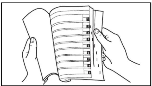
text_image
Line drawing showing hands holding an open notebook with numbered pages, illustrating a specific page layout.EC082000
FINDING THE REQUIRED PAGE
-
This manual consists of seven chapters; "General Information", "Specifications", "Regular inspection and adjustments", "Engine", "Chassis", "Electrical" and "Tuning".
-
The table of contents is at the beginning of the manual. Look over the general layout of the book before finding then required chapter and item. Bend the book at its edge, as shown, to find the required fore edge symbol mark and go to a page for required item and description.
EC083000
MANUAL FORMAT
All of the procedures in this manual are organized in a sequential, step-by-step format. The information has been complied to provide the mechanic with an easy to read, handy reference that contains comprehensive explanations of all disassembly, repair, assembly, and inspection operations. In this revised format, the condition of a faulty component will precede an arrow symbol and the course of action required will follow the symbol, e.g.,
- Bearings
Pitting/Damage → Replace.
EC084002
HOW TO READ DESCRIPTIONS
To help identify parts and clarify procedure steps, there are exploded diagrams at the start of each removal and disassembly section.
- An easy-to-see exploded diagram ① is provided for removal and disassembly jobs.
- Numbers ② are given in the order of the jobs in the exploded diagram. A number that is enclosed by a circle indicates a disassembly step.
- An explanation of jobs and notes is presented in an easy-to-read way by the use of symbol marks ③. The meanings of the symbol marks are given on the next page.
- A job instruction chart ④ accompanies the exploded diagram, providing the order of jobs, names of parts, notes in jobs, etc.
- Extent of removal ⑤ is provided in the job instruction chart to save the trouble of an unnecessary removal job.
- For jobs requiring more information, the step-by-step format supplements ⑥ are given in addition to the exploded diagram and job instruction chart.
text_image
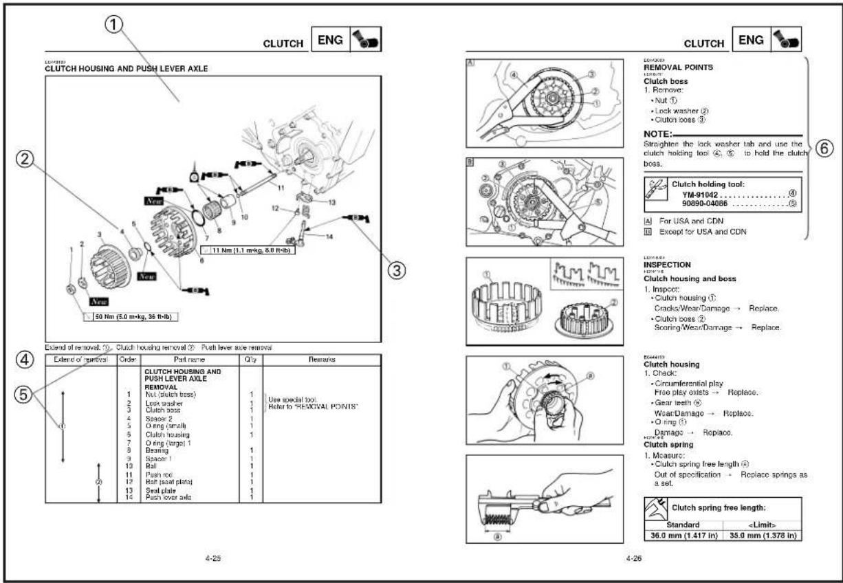
CLUTCH ENG CLUTCH HOUSING AND PUSH LEVER AXLE 11 Nm (1.1 m·kg, 5.0 ft·lb) 50 Nm (5.0 m·kg, 36 ft·lb) Extend of removal: ① Clutch housing removal ② Push lever side removal Extent of nominal Order Part name Q'ty Remarks 1 CLUTCH HOUSING AND PUSH LEVER AXLE REMOVAL Rut (clutch boss) 1 Lock washer 1 Clutch boss 1 Space 2 1 O ring (small) 1 Clutch housing 1 O ring (target) 1 Bearing 1 Space 1 1 Ball 1 Push roe 1 Relt (assat plate) 1 Seal plate 1 Push cover axle 1 4-25 4-26 CLUTCH ENGL REMOVAL POINTS CLUTCH boss 1. Remove: • Nut ① • Lock washer ② • Clutch boss ③ NOTE: Straighter the lock washer tab and use the clutch holding tool ④, ⑤ to hold the clutch boss. Clutch holding tool: YM-91042 .......④ 90890-04086 .......⑤ For USA and CDN Except for USA and CDN INSPCTION CLUTCH HUSING AND BASS 1. Inspect: • Clutch housing ① Cracks/Wear/Damage → Replace. • Clutch boss ② Scoring/Wear/Damage → Replace. ECA#ED Clutch housing 1. Check: • Circumferential play Free play exists → Replace. • Gear teeth ⑥ Wear/Damage → Replace. • O ring ① Dgmaq → Replace. Clutch spring 1. Measure: • Clutch spring free length ④ Cut of specification → Replace springs as a set. Clutch spring free length: Standard1 | 2 |
3 | 4 |
5 | 6 |
7 | 8 |
9 |  |
10 |  |
11 |  |
12 |  |
13 | 19 |
14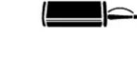 | 21 |
EC085002
ILLUSTRATED SYMBOLS (Refer to the illustration)
Illustrated symbols ① to ⑦ are designed as thumb tabs to indicate the chapter's number and content.
① General information
② Specifications
③ Regular inspection and adjustments
④ Engine
⑤ Chassis
⑥ Electrical
⑦ Tuning
Illustrated symbols ⑧ to ⑭ are used to identify the specifications appearing in the text.
⑧ With engine mounted
⑨ Special tool
⑩ Filling fluid
⑪ Lubricant
⑫ Tightening
⑬ Specified value, Service limit
⑭ Resistance (Ω), Voltage (V), Electric current (A)
Illustrated symbols ⑮ to ⑲ in the exploded diagrams indicate grade of lubricant and location of lubrication point.
⑮ Apply transmission oil
⑯ Apply engine mixing oil
⑰ Apply molybdenum disulfide oil
⑱ Apply lightweight lithium-soap base grease
⑲ Apply molybdenum disulfide grease
Illustrated symbols ⑳ to ㉑ in the exploded diagrams indicate where to apply a locking agent and where to install new parts.
⑳ Apply locking agent (LOCTITE)
②1 Use new one
MEMO
EC090000
INDEX
| GENERAL INFORMATION |  | |
| GEN INFO | 1 | |
| SPECIFICATION |  | |
| SPEC | 2 | |
| REGULAR INSPECTION AND ADJUSTMENTS |  | |
| INSP ADJ | 3 | |
| ENGINE |  | |
| ENG | 4 | |
| CHASSIS |  | |
| CHAS | 5 | |
| ELECTRICAL | 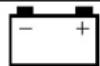 | |
| ELEC | 6 | |
| TUNING |  | |
TU  | 7 | |
CONTENTS
CHAPTER 1
GENERAL INFORMATION
DESCRIPTION....1-1
MACHINE IDENTIFICATION ..... 1-2
IMPORTANT INFORMATION ..... 1-3
CHECKING OF CONNECTION....1-5
SPECIAL TOOLS....1-6
CONTROL FUNCTIONS ..... 1-8
FUEL AND ENGINE MIXING OIL ..... 1-14
INFORMATION BEFORE
PRE-OPERATION 1-15
STARTING AND BREAK-IN ..... 1-16
TORQUE-CHECK POINTS ..... 1-19
CLEANING AND STORAGE ..... 1-21
CHAPTER 2
SPECIFICATIONS
GENERAL SPECIFICATIONS.....2-1
MAINTENANCE SPECIFICATIONS ..... 2-3
GENERAL TORQUE SPECIFICATIONS . 2-12
DEFINITION OF UNITS 2-12
CABLE ROUTING DIAGRAM ..... 2-13
CHAPTER 3
REGULAR INSPECTION
AND ADJUSTMENTS
MAINTENANCE INTERVALS ..... 3-1
PRE-OPERATION INSPECTION AND
MAINTENANCE....3-4
LOCKING WIRE INSTALLATION GUIDE . 3-5
ENGINE 3-6
CHASSIS 3-17
ELECTRICAL....3-42
CHAPTER 4
ENGINE
COWLING, INDUCTION GUIDE, SEAT
AND FUEL TANK....4-1
EXHAUST PIPE AND SILENCER ..... 4-3
RADIATOR....4-4
CARBURETOR AND REED VALVE ..... 4-7
CYLINDER HEAD, CYLINDER AND
PISTON 4-18
CLUTCH....4-31
PRIMARY DRIVEN GEAR, PRIMARY
DRIVE GEAR AND BALANCER
SHAFT 4-38
SHIFT SHAFT 4-44
WATER PUMP 4-51
TRANSMISSION, SHIFT CAM AND
SHIFT FORK 4-55
OIL PUMP 4-64
CDI MAGNETO 4-68
ENGINE REMOVAL 4-71
CRANKCASE AND CRANKSHAFT .... 4-76
CHAPTER 5
CHASSIS
FRONT WHEEL AND REAR WHEEL .... 5-1
FRONT BRAKE AND REAR BRAKE ... 5-10
FRONT FORK 5-26
HANDLEBAR....5-40
STEERING....5-46
SWINGARM....5-53
REAR SHOCK ABSORBER ..... 5-60
CHAPTER 6
ELECTRICAL
ELECTRICAL COMPONENTS AND
WIRING DIAGRAM 6-1
IGNITION SYSTEM 6-2
CHARGING SYSTEM 6-7
YPVS SYSTEM 6-10
SOLENOID VALVE SYSTEM. . . . . . . . 6-12
THERMO UNIT SYSTEM. 6-14
FUEL PUMP SYSTEM....6-16
CHAPTER 7
TUNING
ENGINE 7-1
CHASSIS 7-14
EC100000
GENERAL INFORMATION
EC110000
DESCRIPTION
① Clutch lever
② Valve joint
③ Main switch
④ Water temperature gauge
⑤ Front brake lever
⑥ Throttle grip
⑦ Radiator cap
⑧ Fuel tank cap
⑨ Starter lever (Choke)
⑩ Battery
⑪ Fuel pump
⑫ Fuel cock
⑬ Steering damper
⑭ Servomotor
⑮ Radiator
⑯ Check bolt (Transmission oil level)
⑰ Rear brake pedal
⑱ Rear shock absorber
⑲ Drive chain
⑳ Shift pedal
②1 CDI magneto
②2 Front fork
NOTE:
• The machine you have purchased may differ slightly from those shown in the following.
- Designs and specifications are subject to change without notice.

text_image
Technical diagram of a mechanical assembly with numbered parts for identification
text_image
Technical diagram of a motorcycle with numbered parts for identification
text_image
Technical diagram of a motorcycle with numbered parts labeled 18, 19, 20, 21, and 221

natural_image
Technical line drawing of a mechanical assembly with numbered component (no text or symbols)EC120001
MACHINE IDENTIFICATION
There are two significant reasons for knowing the serial number of your machine:
- When ordering parts, you can give the number to your Yamaha dealer for positive identification of the model you own.
- If your machine is stolen, the authorities will need the number to search for and identify your machine.
EC121001
VEHICLE IDENTIFICATION NUMBER (For USA, CDN, AUS, NZ and E)
The vehicle identification number ① is stamped on the right of the steering head pipe.
EC122001
FRAME SERIAL NUMBER (Except for USA, CDN, AUS, NZ and E)
The frame serial number ① is stamped on the right of the steering head pipe.

text_image
Technical diagram showing a vehicle's seatbelt assembly with labeled component ①EC123020
ENGINE SERIAL NUMBER
The engine serial number ① is stamped into the elevated part of the rear-side of the engine.
text_image
Technical diagram showing mechanical assembly with labeled component 1EC124000
MODEL LABEL
The model label ① is affixed to the frame under the rider's seat. This information will be needed to order spare parts.

natural_image
Illustration of a mechanic cleaning a motorcycle with a bucket nearby (no text or symbols)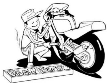
natural_image
Cartoon illustration of a mechanic working on a motorcycle with a tool, no text or symbols present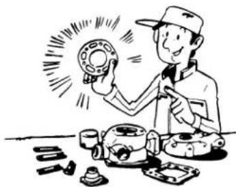
natural_image
Illustration of a mechanic working on a mechanical device with tools and components (no text or symbols)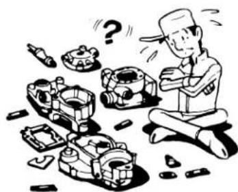
natural_image
Cartoon illustration of a worker assembling mechanical parts with question marks, no text or symbols present
text_image
NO SMOKEEC130000 IMPORTANT INFORMATION
EC131002 PREPARATION FOR REMOVAL AND DIS- ASSEMBLY
-
Remove all dirt, mud, dust, and foreign material before removal and disassembly.
-
Use proper tools and cleaning equipment. Refer to "SPECIAL TOOLS" section.
-
When disassembling the machine, keep mated parts together. They include gears, cylinders, pistons, and other mated parts that have been "mated" through normal wear. Mated parts must be reused as an assembly or replaced.
-
During the machine disassembly, clean all parts and place them in trays in the order of disassembly. This will speed up assembly time and help assure that all parts are correctly reinstalled.
-
Keep away from fire.
text_image
Technical diagram showing two bolted components with a close-up view of a bolt on a surface, labeled with number 1.
text_image
Technical diagram of a mechanical valve assembly with labeled component 1
text_image
Technical diagram of a mechanical assembly with labeled component ② and directional arrow
text_image
Technical diagram showing a mechanical or structural component with numbered parts and directional arrow indicating flow or movement.EC132000
ALL REPLACEMENT PARTS
- We recommend to use Yamaha genuine parts for all replacements. Use oil and/or grease recommended by Yamaha for assembly and adjustment.
EC133000 GASKETS, OIL SEALS AND O-RINGS
- All gaskets, oil seals, and O-rings should be replaced when an engine is overhauled. All gasket surfaces, oil seal lips, and O-rings must be cleaned.
- Properly oil all mating parts and bearings during reassembly. Apply grease to the oil seal lips.
EC134000
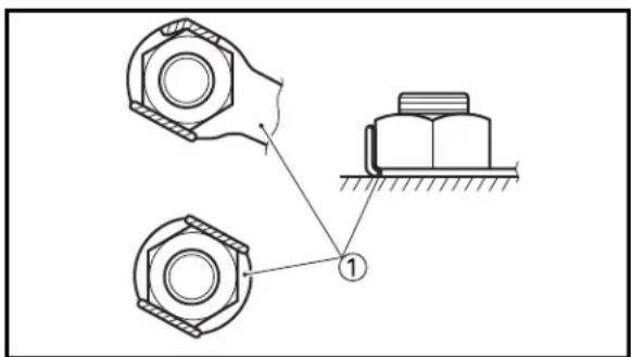
LOCK WASHERS/PLATES AND COTTER PINS
- All lock washers/plates ① and cotter pins must be replaced when they are removed. Lock tab(s) should be bent along the bolt or nut flat(s) after the bolt or nut has been properly tightened.
EC135001
BEARINGS AND OIL SEALS
- Install the bearing(s) ① and oil seal(s) ② with their manufacturer's marks or numbers facing outward. (In other words, the stamped letters must be on the side exposed to view.) When installing oil seal(s), apply a light coating of light-weight lithium base grease to the seal lip(s). Oil the bearings liberally when installing.
CAUTION:
Do not use compressed air to spin the bearings dry. This causes damage to the bearing surfaces.
EC136000
CIRCLIPS
- All circlips should be inspected carefully before reassembly. Always replace piston pin clips after one use. Replace distorted circlips. When installing a circlip ①, make sure that the sharp-edged corner ② is positioned opposite to the thrust ③ it receives. See the sectional view.
④ Shaft
natural_image
Two-panel line drawing showing hands holding small objects, one with a tool and the other with a tool (no text or symbols)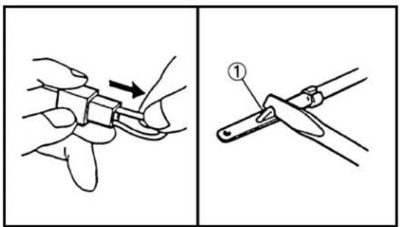
text_image
Technical diagram showing two-step assembly steps of a mechanical clamp or tool, with labeled component ①
natural_image
Pure electrical circuit lines without any symbols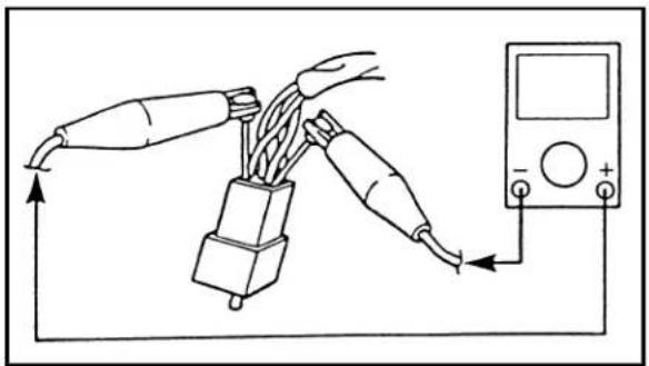
natural_image
Diagram of a multimeter connected to two cable connectors with wires, showing wiring and connection (no text or symbols)EC1C0001
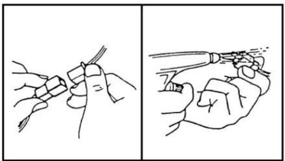
CHECKING OF CONNECTION
Dealing with stains, rust, moisture, etc. on the connector.
- Disconnect:
- Connector
-
Dry each terminal with an air blower.
-
Connect and disconnect the connector two or three times.
- Pull the lead to check that it will not come off.
-
If the terminal comes off, bend up the pin ① and reinsert the terminal into the connector.
-
Connect:
- Connector
NOTE:
The two connectors "click" together.
- Check for continuity with a tester.
NOTE:
- If there in no continuity, clean the terminals.
- Be sure to perform the steps 1 to 7 listed above when checking the wireharness.
- For a field remedy, use a contact revitalizer available on the market.
- Use the tester on the connector as shown.
EC140002
SPECIAL TOOLS
The proper special tools are necessary for complete and accurate tune-up and assembly. Using the correct special tool will help prevent damage caused by the use of improper tools or improvised techniques. The shape and part number used for the special tool differ by country, so two types are provided. Refer to the list provided to avoid errors when placing an order.
NOTE:
- For U.S.A. and Canada, use part number starting with "YM-", "YU-" or "ACC-".
- For others, use part number starting with "90890-".
| Part number Tool name / How to use Illustration | |||
| YM-1189, 90890-01189 Flywheel puller YM-1189 90890-01189This tool is used to remove the flywheel magneto. |  |  | |
| YU-1235, 90890-01235 Rotor holding tool YU-1235 90890-01235This tool is used when loosening or tightening the flywheel magneto securing nut. | 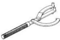 | 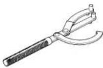 | |
| YU-3097, 90890-01252 Dial gauge and standYU-1256 Spark plug hole dial standYU-1037 Offset dial stand These tools are used to set the ignition timing. | YU-3097 YU-1256 YU-1037 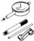 | 90890-01252  | |
| YU-1304, 90890-01304 Piston pin puller This tool is used to remove the piston pin. | YU-1304  | 90890-01304  | |
| YM-1312-A, 90890-01312 YM-1470, 90890-01470 Fuel level gauge adapter This gauge is used to measure the fuel level in the float chamber. | YM-1312-A YM-1470 90890-01470 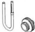 | 90890-01312  | |
| YU-24460-01, 90890-01325 YU-33984, 90890-01352 | Radiator cap tester Adapter These tools are used for checking the cooling system. | YU-24460-01 YU-33984  | 90890-01325 90890-01352 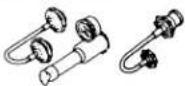 |
| YU-33975, 90890-01403 | Ring nut wrench This tool is used when tighten the steering ring nut to specification. | YU-33975  | 90890-01403 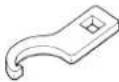 |
| YM-1425, 90890-01425 Damper rod holder YM-1425 90890-01425Use this tool to remove and install the damper rod. | 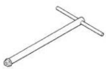 |  | |
| YM-1434, 90890-01434 Rod holder YM-1434 90890-01434This tool is used to hold the fork spring. |  | 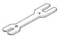 | |
| 90890-01435 Rod puller attachment YM-1437 90890-01435YM-1437, 90890-01437 Rod puller 90890-01437These tools are used to pull up the fork damper rod. |  | 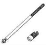 | |
| YM-1441, 90890-01441 Fork spring compressor YM-1441 90890-01441This tool is used to compress the fork spring. |  | 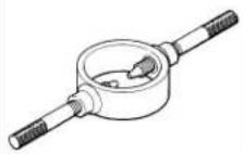 | |
| YM-1442, 90890-01442 Fork seal driver YM-1442 90890-01442This tool is used when install the fork oil seal. | 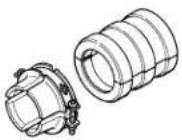 |  | |
| YM-1455, 90890-01455 Pivot shaft wrenchYM-1476, 90890-01476 Pivot shaft wrench adapterThese tools are used to loosen or tighten the pivot adjust bolt. | YM-1455 90890-01455YM-1476 90890-01476 | 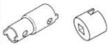 | |
| YU-3112-C, 90890-03112 | Yamaha pocket testerUse this tool to inspect the coil resistance, output voltage and amperage. | YU-3112-C 90890-03112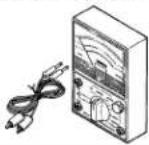 |  |
| YM-91042, 90890-04086 | Clutch holding toolThis tool is used to hold the clutch when removing or installing the clutch boss securing nut. | YM-91042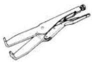 | 90890-04086 |
| YM-3448790890-06754 Ignition checker | Dynamic spark testerThis instrument is necessary for checking the ignition system components. | YM-34487 | 90890-06754 |
| ACC-YAMAB-ON-D490890-05143 YAMAHA Bond No.4 | Quick gasket®This sealant (Bond) is used for crankcase mating surface, etc. | ACC-YAMAB-ON-D4 | 90890-05143 |

natural_image
Mechanical assembly diagram showing a lever mechanism with no visible text or symbols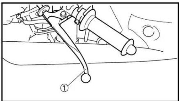
text_image
Technical diagram showing mechanical assembly with labeled component ①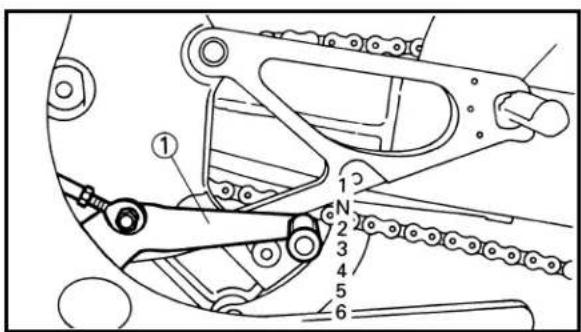
text_image
Technical diagram of a mechanical linkage system with numbered components and labeled parts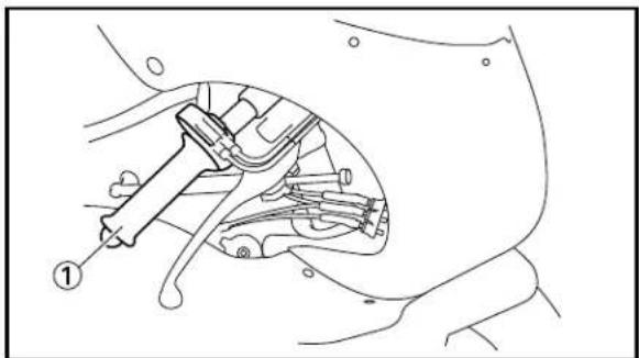
natural_image
Technical line drawing of a mechanical assembly with labeled component (1), no readable text or symbols present
text_image
Technical diagram of a bicycle steering mechanism with labeled component ①EC150000
CONTROL FUNCTIONS
EC15W000
MAIN SWITCH
While the battery is connected, moving the main switch ① to "RUN" causes the tachometer, servomotor, fuel pump and solenoid valves to be initially activated. To prevent the battery from being discharge, do not move the main switch to "RUN" except when the engine is started or when electric parts are checked.
EC152000
CLUTCH LEVER
The clutch lever ① is located on the left handlebar; it disengages or engages the clutch. Pull the clutch lever to the handlebar to disengage the clutch, and release the lever to engage the clutch. The lever should be pulled rapidly and released slowly for smooth starts.
EC153000
SHIFT PEDAL
The gear ratios of the constant-mesh 6 speed transmission are ideally spaced. The gears can be shifted by using the shift pedal ① on the left side of the engine.
EC155001
THROTTLE GRIP
The throttle grip ① is located on the right handlebar; it accelerates or decelerates the engine. For acceleration, turn the grip toward you; for deceleration, turn it away from you.
EC156000
FRONT BRAKE LEVER
The front brake lever ① is located on the right handlebar. Pull it toward the handlebar to activate the front brake.

natural_image
Technical line drawing of a mechanical linkage assembly (no text or symbols)
text_image
OFF ON FUEL ON
natural_image
Technical line drawing of a mechanical lever assembly (no text or symbols)
text_image
1 b a KT0000mm 14 8 9 10 11 12 13 14 2 2 1EC157000
REAR BRAKE PEDAL
The rear brake pedal ① is located on the right side of the machine. Press down on the brake pedal to activate the rear brake.
EC158001
FUEL COCK
The fuel cock supplies fuel from the tank to carburetor while filtering the fuel. The fuel cock has the two positions:
OFF: With the lever in this position, fuel will not flow. Always return the lever to this position when the engine is not running.
ON: With the lever in this position, fuel flows to the carburetor. Normal riding is done with the lever in this position.
EC15A020
When cold, the engine requires a richer air-fuel mixture for starting. A separate starter circuit, which is controlled by the starter lever ①, supplies this mixture. Push the starter lever out to open the circuit for starting. When the engine has warmed up pull it in to close the circuit.
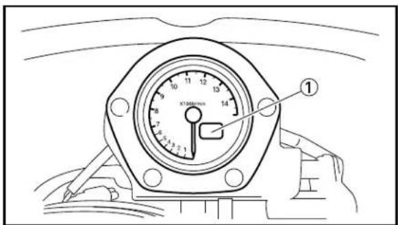
TACHOMETER
A stepping motor type tachometer with greater accuracy and response is provide for the tachometer ①. This tachometer features the following:
Sweeping:
Moving the main switch to "RUN", the tachometer hand sweeps widely once over the tachometer face and then returns to the zero position, as initial operation. This is called "sweeping". When the engine is started during sweeping, the tachometer indicates the correct revolutions after sweeping is over.
Out-of-step indication:
If this tachometer is subjected to impact, etc, it may allow its hand to point to the position ⓑ stepping out of the position ⓐ where the hand should be for correct indication. This is called an “out-of-step” indication. A similar phenomenon may take place when the main switch is moved to “OFF” during sweeping or at high rpm (as in a plug chop) or while the machine is transported, though it never happens in normal riding.
text_image
Technical diagram of a dial indicator with numbered scale and pointer, showing hand positioning and measurement setup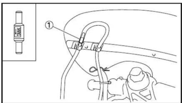
text_image
① TANK
text_image
Technical diagram of a vehicle suspension system with labeled components and a magnified inset showing internal components.NOTE:
- If an out-of-step indication takes place, moving the main switch to "OFF" once and then to "RUN", brings the tachometer back to a normal indication through its corrective action.
- There is no functional problem involved with the out-of-step indication, which can be brought back to a normal indication through the corrective action of the tachometer.
EC15B010
WATER TEMPERATURE GAUGE
The water temperature gauge ① displays different indications according to the change in the water temperature.
NOTE:
Water temperature may be 70 °C (158 °F) when engine is operated in good conditions.
| Cooling water temp. | Display Conditions | |
| ~19 °C (~66 °F) | “LO” is display. | |
| 20~119 °C Temperature is (68~247 °F) displayed. | ||
| 120~140 °C Temperature (248~284 °F) flash. | ||
| 141 °C~Message (285 °F~) | flash. | |
EC15F000
VALVE JOINT
This valve joint ① prevents fuel from flowing out and is installed to the fuel tank breather hose.
CAUTION:
In this installation, make sure the arrow faces the fuel tank and also downward.
EC15X000
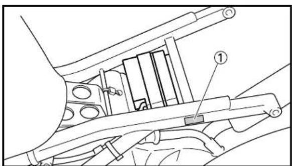
BATTERY
The battery ① is provided as power supply for the electric parts. Except when the machine is run, disconnect the power supply coupler ② of the wireharness to prevent battery discharge.
text_image
Technical diagram of a mechanical assembly with numbered components, likely illustrating a gear or linkage mechanism.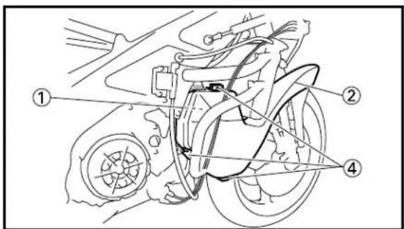
text_image
Technical diagram of a motorcycle's internal components with numbered labels pointing to different parts.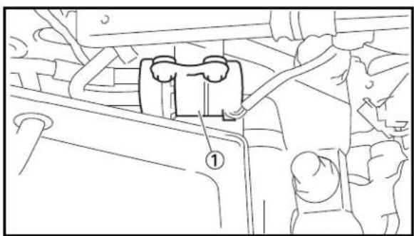
natural_image
Technical line drawing of a mechanical assembly with numbered component (no text or symbols)EC15Y000
The induction boxes ① and induction guides ② are provided for the purpose of applying pressure inside the carburetor float chamber and thereby improving the intake performance. If the machine is run without them, the carburetor settings will become faulty.
NOTE:
Be sure to fix the induction guides with band ③ or hooks ④ so that they do not come off by wind pressure while running.
EC15Z000
FUEL PUMP
The fuel pump ①, is provided in order to provide steady supply of fuel even when the pressure inside the carburetor float chamber becomes higher than inside the fuel tank because of the induction box intake system. If the fuel level is not up to the specified level in the float chamber, this pump is activated (with an operation sound) and stops operating when the specified level is reached.
CAUTION:
Do not idle run the fuel pump with no fuel flowing as when the fuel tank is empty or when the fuel cock is "OFF". It may damage the fuel pump.

text_image
① ② a UPPER
text_image
Electrical circuit diagram with labeled components including power source, switch, transformer, and motor
text_image
Technical diagram of a mechanical assembly with numbered components, likely for assembly or maintenance instructions.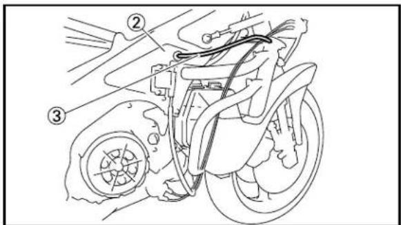
text_image
Technical diagram of a motorcycle's front wheel assembly with numbered parts labeled ②, ③, and ②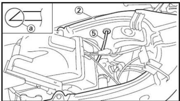
text_image
Technical diagram of a car engine showing labeled parts and a magnified inset with section line 'a'EC15a000 FUEL PUMP STOP SWITCH, FUEL PUMP RELAY
The fuel pump stop switch ① and fuel pump relay ② are provided so as to control the fuel pump and prevent the carburetor overflowing during a turnover.
If the machine is turned over, the fuel pump stop switch is turned "ON" which allow electric current to flow in the coil ③ inside the relay, causing the relay switch ④ to turn "OFF" and shutting of the electric current flow to the fuel pump ⑤. Thus, the pump comes to a stop.
| Fuel pump Fstop switch 1 | fuel pumprelay switch 4 | Fuel pump 5 | |
| During run | OFF ON ON | ||
| Duringturnover | ON OFF | OFF |
NOTE:
- When the machine is picked up from turnover, the fuel pump is restored to an operation condition.
- Install the fuel pump stop switch so that "UPPER" mark ⓐ faces upward.
EC15M011
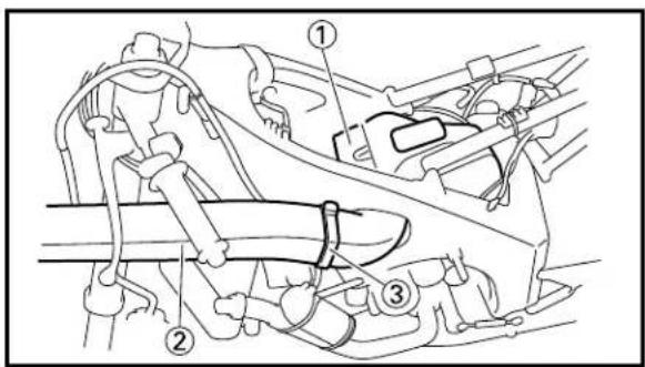
CATCH TANK
Put the tip of the breather hose into the catch tank ① and frame ②. Take care not to allow the fuel, oil and cooling water to spill on the course.
③ Radiator breather hose
④ Fuel tank breather hose
⑤ Transmission oil breather hose
NOTE:
When putting in the transmission oil breather hose, its tip having a cut ⓐ should be on the frame side.
text_image
Technical diagram showing mechanical assembly with numbered components, likely illustrating a gear or cam mechanism.
natural_image
Mechanical assembly diagram showing a linkage mechanism with no visible text or symbols
text_image
Diagram showing a hand using a tool to press or install a component, labeled with parts ① and ②.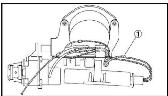
natural_image
Technical line drawing of a mechanical device with labeled component (no text or symbols present)EC15Q001
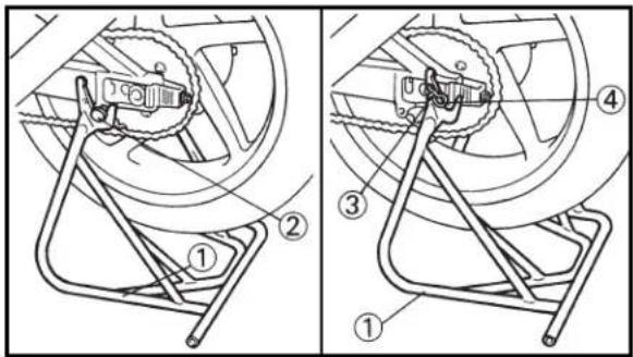
DETACHABLE MAINSTAND
This mainstand ① is used to support only the machine when standing or transporting it.
NOTE:
The mainstand can be used to support the machine two ways.
- Hook the bracket of the mainstand onto the swingarm hooks ②.
- Stand shaft (with supplying parts):
Insert the stand shaft ③ through the hole of the mainstand and rear wheel axle. Be sure to install the clip ④ in the end of the stand shaft.
WARNING
- Never apply additional force to the mainstand.
- Remove this mainstand before starting out.
EC15R001
DETACHABLE SIDESTAND
This sidestand ① is used to support only the machine when standing or transporting it.
WARNING
- Never apply additional force to the side-stand.
- Remove this sidestand before starting out.
EC15T003
FIRE RETARDANT MATERIAL
For racing, be sure to fill the fuel tank ② completely with fire retardant material (with supplying parts) ①.
EC15b000
COUPLER FOR SPEED SHIFT
If an after-marked speed shift is installed, the coupler ① should be used.
NOTE:
If the speed shift is not installed, be sure to fix the coupler to the wireharness using a vinyl tape, for protection against water entry as well because if the coupler contacts the frame, sparks will be shut off, causing the engine to stop.
EC160040
FUEL AND ENGINE MIXING OIL
Mix oil with the gas at the ratio specified below. Always use fresh, name-brand gasoline, and mix the oil and gas the day of the race. Do not use premix that is more than a few hours old.

Recommended fuel:
Except for AUS:
Premium unleaded fuel with a research octane number of 95 or higher.
For AUS:
Unleaded fuel only
NOTE:
Except for AUS:
- If knocking or pinging occurs, use a different brand of gasoline or higher octane grade.
- If unleaded gasoline is not available, then leaded gasoline can be used.
CAUTION:
Never mix two types of oil in the same batch; clotting of the oil could result. If you wish to change oil types, be sure to drain the fuel tank and the carburetor float bowl of old premix prior to filling with the new type.

text_image
30 : CASTROL A747 1
Fuel tank capacity: 23.0 L (5.06 Imp gal, 6.08 US gal)

Mixing oil Recommended oil: Castrol A747 Mixing ratio: 30 : 1

text_image
Technical diagram of a mechanical assembly with labeled components and circular motion pathsEC170011
INFORMATION BEFORE PRE- OPERATION
- The brake disc ① is coated with a rust inhibitor. Before riding the machine, thoroughly remove it using a lacquer thinner.
WARNING
• LACQUER THINNER IS HIGHLY FLAMMABLE.
Always turn off the engine while using lacquer thinner. Take care not to spill any lacquer thinner on the engine or exhaust system.
Never use it in the vicinity of an open flame, or while smoking.
- LACQUER THINNER CAN CAUSE INJURY. Always use lacquer thinner in a well ventilated area. If you should swallow some lacquer thinner, inhale excess lacquer thinner vapors, or allow any lacquer thinner to get into your eyes, contact a doctor immediately.
NOTE:
- When the machine is not in use for a long time, apply a rust inhibitor to the brake disc.
•After riding in the rainy weather, wipe the moisture completely off the disc.
- If rust appears on the brake disc, carefully remove it using #400 sand paper.
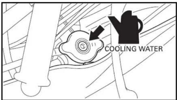
text_image
COOLING WATER- The cooling system is filled with coolant at the factory to prevent rusting. Be sure to replace coolant with soft water before rid-ing.
CAUTION:
Hard water or salt water is harmful to the engine parts. You may use distilled water, if you can't get soft water.
EC190000
STARTING AND BREAK-IN
CAUTION:
Before starting the machine, perform the checks in the pre-operation check list.
WARNING
Never start or run the engine in a closed area. The exhaust fumes are poisonous; they can cause loss of consciousness and death in a very short time. Always operate the machine in a well-ventilated area.
EC191032
STARTING A COLD ENGINE
- Connect the power supply coupler.
- Turn the fuel cock to "ON" and push the starter lever (CHOKE).
- Move the main switch to "RUN".
- Shift the transmission into "1st" gear.
- Apply the clutch lever and push the machine.
- After gaining some momentum, release the clutch lever.
- As soon as the engine starts, quickly apply the clutch lever again and open the throttle grip slightly at the same time so as to sustain idling of the engine. Then, shift the transmission into neutral.
- After applying full-throttle a few times, turn the starter lever (CHOKE) to the original position. Take some time to allow the engine to warm up.
EC192000
WARMING UP
Run the engine at varying speeds 5,000\~6,000 r/min for 1\~2 minutes. Fully warm up until the water temperature gauge reads 70 °C (158 °F) or so.
CAUTION:
Do not warm up the engine for extended periods.
EC193031
STARTING A WARM ENGINE
Do not push the starter lever (CHOKE). Open the throttle slightly and start the engine.
CAUTION:
Observe the following break-in procedure during initial operation to ensure optimum performance and avoid engine damage.
EC194020
BREAK-IN PROCEDURES
- Before starting the engine, fill the fuel tank with a break-in oil-fuel mixture as follows.

Mixing oil
Recommended oil:
Castrol A747
Mixing ratio: 30 : 1
- Perform the pre-operation checks on the machine.
- Start and warm up the engine. Check the operation of the controls and check that the engine comes to a stop when moving the main switch to "OFF".
NOTE:
During break-in, mask part of the radiator core so that the water temperature is 55 \~ 65°C (131 \~ 149°F).
- Operate the machine under 8,000 r/min and run on a course about 10 km (6 miles). While making a straight-line run, open the throttle from time to time, taking care not to exceed the revolution limit.
- Go back to the pit to check for looseness, leakage, and other failures in installation.
- Next, operate the machine under 9,000 r/min and run about 10 km (6 miles). (While running in this way, get an idea of the riding position and approximate settings.)
- Go back to the pit again, check the machine fully for looseness, leakage, and other failures in installation, especially for loose cables and wires, excessive brake free play, and a chain slack. Also make adjustment for a riding position according to your preference.
CAUTION:
After the break-in or before each race, you must check the entire machine for loose fittings and fasteners as per "TORQUE-CHECK POINTS".
Tighten all such fasteners as required.
- Increase the engine speed up to 10,000 r/min and run about 10 km (6 miles).
- Increase the engine speed up to 11,000 r/min and run about 10 km (6 miles).
- Increase the engine speed up to 12,000 r/min and run about 10 km (6 miles). Then do the plug chop. Check the piston head for burning to see if there is any problem. Refer to "SETTING" section in the CHAPTER 7.
- Run about 10 km (6 miles) in a usual manner. Then do the plug chop. Check the piston head for burning to see if there is any problem.
EC195001
BREAKING IN AFTER REPLACEMENT
After a part is replaced with a new one, it is necessary to break it in as in a new machine. This is required especially when the following engine-related parts are replaced.
•Cylinder •Piston •Piston ring
•Crankshaft •Clutch •Transmission gear
- Shift fork
※ For warming up and inspection during break-in, refer to “PRE-OPERATION CHECK LIST” and if there is any problem, stop the engine immediately and check.
EC1A0060
TORQUE-CHECK POINTS
Frame construction Frame to rear frame
Engine mounting Frame to engine
Steering Steering shaft to handlebar Steering damper stay to front fork
Steering shaft to handle crown Front fork to handlebar

flowchart
graph TD
    A["Suspension"] --> B["Front"]
    B --> C["Steering shaft to front fork"]
    C --> D["Front fork to handle crown"]
    C --> E["Front fork to under bracket"]
    A --> F["Rear For link-type Assembly of links"]
    F --> G["Link to frame"]
    F --> H["Link to shock absorber"]
    F --> I["Link to swingarm"]
    A --> J["Rear Installation of shock absorber Shock absorber to upper bracket"]
    J --> K["Adjuster to upper bracket"]
    J --> L["Adjuster to locknut"]
    A --> M["Rear Installation of swingarm Tightening of pivot shaft"]
Wheel Installation of wheel Front Tightening of front axle Rear Tightening of rear axle Sprocket damper to sprocket

flowchart
graph TD
    A["Brake"] --> B["Hydraulic type"]
    B --> C["Front Caliper to front fork"]
    C --> D1["Brake disc to wheel"]
    C --> D2["Tightening of union bolt"]
    C --> D3["Caliper to adapter"]
    C --> D4["Brake hose to adapter"]
    C --> D5["Master cylinder to handlebar"]
    C --> D6["Tightening of air bleeder"]
    C --> D7["Caliper to pad pin"]
    B --> E["Rear"]
    E --> F1["Caliper to caliper bracket"]
    E --> F2["Brake disc to wheel"]
    E --> F3["Tightening of union bolt"]
    E --> F4["Caliper to adapter"]
    E --> F5["Brake hose to adapter"]
    E --> F6["Master cylinder to footrest bracket"]
    E --> F7["Footrest bracket to frame"]
    E --> F8["Footrest bracket to footrest"]
    E --> F9["Brake pedal to master cylinder"]
    E --> F10["Tightening of air bleeder"]
    E --> F11["Caliper to pad pin"]
Fuel system Fuel tank to fuel cock
NOTE:
Concerning the tightening torque, refer to "MAINTENANCE SPECIFICATIONS" section in the CHAPTER 2.
EC1B0000
CLEANING AND STORAGE
EC1B1000
CLEANING
Frequent cleaning of your machine will enhance its appearance, maintain good overall performance, and extend the life of many components.
-
Before washing the machine, block off the end of the exhaust pipe to prevent water from entering. A plastic bag secured with a rubber band may be used for this purpose.
-
If the engine is excessively greasy, apply some degreaser to it with a paint brush. Do not apply degreaser to the chain, sprockets, or wheel axles.
-
Rinse the dirt and degreaser off with a garden hose; use only enough pressure to do the job.
CAUTION:
Excessive hose pressure may cause water seepage and contamination of wheel bearings, front forks, brakes and transmission seals. Many expensive repair bills have resulted from improper high pressure detergent applications such as those available in coin-operated car washers.
-
After the majority of the dirt has been hosed off, wash all surfaces with warm water and a mild detergent. Use an old toothbrush to clean hard-to-reach places.
-
Rinse the machine off immediately with clean water, and dry all surfaces with a soft towel or cloth.
-
Immediately after washing, remove excess water from the chain with a paper towel and lubricate the chain to prevent rust.
-
Clean the seat with a vinyl upholstery cleaner to keep the cover pliable and glossy.
-
Automotive wax may be applied to all painted or chromed surfaces. Avoid combination cleaner-waxes, as they may contain abrasives.
-
After completing the above, start the engine and allow it to idle for several minutes.
EC1B2010
STORAGE
If your machine is to be stored for 60 days or more, some preventive measures must be taken to avoid deterioration. After cleaning the machine thoroughly, prepare it for storage as follows:
- Drain the fuel tank, fuel lines, and the carburetor float chambers.
- Remove the spark plugs, pour a tablespoon of SAE 10W30 motor oil in the spark plug hole, and reinstall the plug. With the engine stop switch pushed in, kick the engine over several times to coat the cylinder walls with oil.
- Remove the drive chain, clean it thoroughly with solvent, and lubricate it. Reinstall the chain or store it in a plastic bag tied to the frame.
- Lubricate all control cables.
- Block the frame up to raise the wheels off the ground.
- Tie a plastic bag over the exhaust pipe outlet to prevent moisture from entering.
- If the machine is to be stored in a humid or salt-air environment, coat all exposed metal surfaces with a film of light oil. Do not apply oil to rubber parts or the seat cover.
- Drain the cooling water completely. And then fill the coolant and water (50%:50%) in the engine and radiator.
NOTE:
Make any necessary repairs before the machine is stored.
EC200000
SPECIFICATIONS
EC211000
GENERAL SPECIFICATIONS
| Model name: TZ250N1 (USA) | TZ250(N) (OTHERS) |
| Model code number: 5KE2 | |
| Dimensions:Overall length 1,955 mm (77.0 in)Overall width 650 mm (25.6 in)Overall height 1,083 mm (42.6 in)Seat height 788 mm (31.0 in)Wheelbase 1,342 mm (52.8 in)Minimum ground clearance 112 mm (4.4 in) | |
| Basic weight:With oil and full fuel tank 119.5 kg (263 lb) | |
| Engine:Engine type Liquid cooled 2-stroke, gasolineCylinder arrangement V-type, 2-cylinderDisplacement 249 cmBore×Stroke 54×54.5 mm (2.126×2.146 in)Compression ratio 7.2 : 1Starting system | ^3 (8.76 Imp oz, 8.42 US oz)Push to start |
| Lubrication system: Premix (30 : 1) (Castrol A747) | |
| Oil type or grade (2-Cycle):Transmission oilPeriodic oil changeTotal amount 0.5 L (0.44 Imp qt, 0.53 US qt) | Castrol R300.5 L (0.44 Imp qt, 0.53 US qt) |
| Cooling water capacity (including all routes): | 1.4 L (1.23 Imp qt, 1.48 US qt) |
| Fuel:TypeTank capacity 23.0 L (5.06 Imp gal, 6.08 US gal) | Except for AUS: Premium unleaded fuel with a research octane number of 95 or higherFor AUS: Unleaded fuel only |
| Carburetor:Type/Manufacturer | TMXx38/MIKUNI |
| Spark plug:Type/ManufacturerGap | R6179A-105P/NGK0.5~0.6 mm (0.020~0.024 in) |
| Clutch type: | Dry, multiple-disc |

| Transmission:primary reduction system Spur gearPrimary reduction ratio 53/21 (2.524)Secondary reduction system Chain driveSecondary reduction ratio 36/14 (2.571)Transmission type Constant mesh, 6-speedOperation Left foot operationGear ratio: 1st 34/18 (1.889)2nd 31/21 (1.476)3rd 29/23 (1.261)4th 27/25 (1.080)5th 26/27 (0.963)6th 20/22 (0.909) | |
| Chassis:Frame type Delta boxCaster angle 22°Trail | 82 mm (3.23 in) |
| Tire:TypeSize (front)Size (rear)Tire pressure (front and rear) | Tubeless3.10/4.80 R17165/55 R17200 kPa (2.0 kg/cm2, 29 psi) |
| Brake:Front brake typeOperation Right hand operationRear brake typeOperation Right foot operation | Dual disc brakeSingle disc brake |
| Suspension:Front suspensionRear suspension | Telescopic forkSwingarm (link type monocross suspension) |
| Shock absorber:Front shock absorberRear shock absorber | Coil spring/oil damperCoil spring/gas, oil damper |
| Wheel travel:Front wheel travelRear wheel travel | 113 mm (4.45 in)118 mm (4.65 in) |
| Electrical:Ignition system | CDI magneto |
EC212000
MAINTENANCE SPECIFICATIONS
EC212112
ENGINE
| Item Standard Limit | ||
| Cylinder head:Combustion chamber capacity 9.0 cm | 3(0.317 Imp oz, 0.304 US oz) | ... |
| Piston:Piston clearance 0.090~0.100 mm ...Piston offset 1.0 mm (0.039 in)/EX-side ... | (0.0035~0.0039 in) | |
| Piston pin:Piston pin outside diameter 14.995~15.000 mm 14.975 mm(0.5904~0.5906 in) (0.5896 in) | ||
Piston ring:Sectional sketch Keyston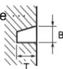 End gap (installed)Side clearance (installed) End gap (installed)Side clearance (installed) | B=1.0 mm (0.039 in) ...T=2.2 mm (0.087 in) ...0.22~0.37 mm (0.009~0.015 in)Zero~0.06 mm (Zero~0.0024 in) | 0.59 mm (0.023 in)... |
Crankshaft: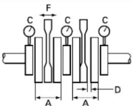 Crank width “A”Runout limit “C”Connecting rod big endside clearance “D”Small end free play “F” Crank width “A”Runout limit “C”Connecting rod big endside clearance “D”Small end free play “F” | 49.975~50.025 mm (1.968~1.969 in)0.03 mm (0.0012 in)0.45~0.95 mm (0.018~0.037 in)0.8~1.0 mm (0.031~0.039 in) | ...0.05 mm (0.0020 in)...2.0 mm (0.08 in) |
| Clutch:Friction plate thicknessQuantityClutch plate thicknessQuantityWarp limitClutch spring free lengthQuantityClutch housing thrust clearanceClutch housing radial clearanceClutch release methodPush rod bending limit | 2.9~3.1 mm (0.114~0.122 in)62.2~2.4 mm (0.087~0.094 in)5...30.6 mm (1.205 in)60.07~0.18 mm (0.003~0.007 in)0.009~0.071 mm(0.0004~0.0028 in)Inner push, cam push... | 2.7 mm (0.106 in)......0.1 mm (0.004 in)29.6 mm (1.165 in)...............0.2mm (0.008 in) |
| Transmission:Main axle deflection limitDrive axle deflection limit | ...... | 0.01 mm (0.0004 in)0.01 mm (0.0004 in) |
| Shifter:Shifting type Cam drum and guide barGuide bar bending limit | ...... | 0.04 mm (0.0016 in) |
| Carburetor:Type/Manufacturer TMXx38/MIKUNI ...I.D. mark (left side/right side) 5KE2 10L/5KE2 10R ...Main jet (M.J.) #560 ...Jet needle (J.N.) 6DGJ1Main nozzle (N.J.) S-4Cutaway (C.A.)Pilot jet (P.J.)Pilot air screw (P.A.S.)Valve seat size (V.S.) 1.5Starter jet (G.S.)Power jet (P.W.J.)Float height (F.H.) | ... | ... |
| 5.0 | ... | |
| #40 | ... | |
| 1-1/2 | ... | |
| ... | ... | |
| #80 | ... | |
| #55 | ... | |
| 6.0~7.0 mm (0.24~0.28 in) | ... | |
Reed valve:Thickness* reed valve 1reed valve 2'Valve stopper height  Valve bending limit Valve bending limit | 0.42 mm (0.017 in)0.34 mm (0.013 in) ...6.5~6.9 mm (0.256~0.272 in)... | ... |
| ... | ||
| 0.2 mm (0.008 in) | ||
| Cooling:Radiator core size:WidthHeightThicknessRadiator cap opening pressureRadiator capacity 0.5 L (0.44 Imp qt, 0.53 US qt)Water pump:Type | 380 mm (14.96 in)198 mm (7.80 in)24 mm (0.94 in)95~125 kPa(0.95~1.25 kg/cm2, 13.5~17.8 psi) | ... |
| ... | ||
| ... | ||
| ... | ||
| ... | ||
| ... | ||
| ... | ||
| ... | ||
| ... |
| Part to be tightened Thread size | Q'ty | Tightening torque | |||
| Nm | kg ft·lb | ||||
| Spark plug | M14S × 1.25 | 2 19 1.9 | 13 | ||
| Cylinder head (bolt) M 6 × 1.0 12 11 1.1 8.0 | |||||
| Cylinder (nut) | M 8 × 1.25 | 8 20 2.0 | 14 | ||
| (stud) | M 8 × 1.25 | 8 15 1.5 | 11 | ||
| Power valve: | |||||
| Cover | M 5 × 0.8 | 8 | 4 | 0.4 | 2.9 |
| Holder (power valve) | M 5 × 0.8 | 2 | 9 | 0.9 | 6.5 |
| Pulley | M 5 × 0.8 | 2 | 4 | 0.4 | 2.9 |
| Cable stay | M 5 × 0.8 | 4 | 7 | 0.7 | 5.1 |
| Air bleeding bolt (cylinder) | M 6 × 1.0 | 2 | 12 | 1.2 | 8.7 |
| Balance weight gear | M14 × 1.0 | 1 | 50 | 5.0 | 36 |
| Water pump housing cover | M 6 × 1.0 | 4 | 11 | 1.1 | 8.0 |
| Air bleeding bolt (water pump) | M 6 × 1.0 | 1 | 11 | 1.1 | 8.0 |
| Radiator | M 6 × 1.0 | 3 | 7 | 0.7 | 5.1 |
| Radiator and thermo unit | M16 × 1.5 | 1 | 11 | 1.1 | 8.0 |
| Radiator hose clamp | - | 6 | 2 | 0.2 | 1.4 |
| Oil pump cover | M 5 × 0.8 | 3 | 8 | 0.8 | 5.8 |
| Oil strainer | M 6 × 1.0 | 4 | 7 | 0.7 | 5.1 |
| Carburetor joint | M 6 × 1.0 | 9 11 1.1 | 8.0 | ||
| Clamp (carburetor joint) | M 4 × 0.7 | 2 | 2 | 0.2 | 1.4 |
| Reed valve | M 3 × 0.5 | 12 1 | 0.1 | 0.7 | |
| Mixing chamber top | M 4 × 0.7 | 2 | 2 | 0.2 | 1.4 |
| Exhaust pipe | M 8 × 1.25 | 2 21 2.1 | 15 | ||
| Silencer | M 6 × 1.0 | 4 11 1.1 | 8.0 | ||
| Crankcase | M 8 × 1.25 | 6 | Refer to NOTE | ||
| Crankcase | M 6 × 1.0 | 9 | |||
| Transmission housing | M 6 × 1.0 | 6 | 16 | 1.6 | 11 |
| Oil check bolt | M 6 × 1.0 | 1 | 9 | 0.9 | 6.5 |
| Oil drain bolt | M12 × 1.25 | 1 23 2.3 | 17 | ||
| Crankcase cover (right) | M 6 × 1.0 | 10 11 1.1 | 8.0 | ||
| Crankcase cover (left) | M 6 × 1.0 | 3 | 11 | 1.1 | 8.0 |
| Primary drive gear | M10 × 1.25 | 1 55 5.5 | 40 | ||
| Clutch boss | M20 × 1.0 | 1 | 75 | 7.5 | 54 |
| Clutch spring | M 6 × 1.0 | 6 | 9 | 0.9 | 6.5 |
| Push rod adjuster | M 6 × 1.0 | 1 | 6 | 0.6 | 4.3 |
| Seat plate (push lever) | M 5 × 0.8 | 1 | 7 | 0.7 | 5.1 |
| Clutch cable holder | M 6 × 1.0 | 2 | 8 | 0.8 | 5.8 |
| Bearing plate cover | M 6 × 1.0 | 3 | 10 | 1.0 | 7.2 |
| Oil seal plate cover | M 5 × 0.8 | 2 | 7 | 0.7 | 5.1 |
| Drive sprocket | M20 × 1.0 | 1 | 75 | 7.5 | 54 |
| Bearing plate cover (shift cam) | M 5 × 0.8 | 1 | 4 | 0.4 | 2.9 |
| Segment | M 8 × 1.25 | 1 23 2.3 | 17 | ||
| Shift guide | M 6 × 1.0 | 2 | 11 | 1.1 | 8.0 |
| Shift lever adjuster and locknut | M 6 × 1.0 | 1 | 9 | 0.9 | 6.5 |
| Stopper bolt (torsion spring) | M 8 × 1.25 | 1 | 8 | 0.8 | 5.8 |
| Shift arm | M 6 × 1.0 | 1 14 1.4 | 10 | ||
MAINTENANCE SPECIFICATIONS
SPEC

| Part to be tightened Thread size | Q'ty | Tightening torque | |||
| Nm m | kg ft·lb | ||||
| Joint rod 1 and shift rod M 6 × 1.0 1 9 0.9 6.5Joint rod 2 and shift rod M 6 × 1.0 1 9 0.9 6.5Joint rod 1,2 M 6 × 1.0 2 11 1.1 8.0Shift pedal pivot boltFront pedal | M 8 × 1.25 1M 6 × 1.0 1 10 | 1 | 22 | 2.2 | 16 |
| 1.0 7.2 | |||||
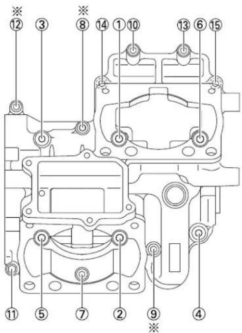
Crankcase tightening sequence
text_image
Technical diagram of a mechanical component with numbered parts for identificationCAUTION:
The M6 bolt comes in two lengths. Use the correct one for installation.
=30 mm (1.18 in) (green) ⑦ ⑩ ⑪ ⑬ ⑭ ⑮
Mark ※: ℓ=35 mm (1.38 in) (silver) ⑧ ⑨ ⑫
NOTE:
Tighten all bolts in 2 steps as follows and be sure to tighten in numbered order as shown.
-First: ①\~⑥ (M8) 11 Nm (1.1 m·kg, 8.0 ft·lb)
⑦\~⑮ (M6) 6 Nm (0.6 m·kg, 4.3 ft·lb)
•Final: ①\~⑥ (M8) 26 Nm (2.6 m·kg, 19 ft·lb)
⑦\~⑮ (M6) 11 Nm (1.1 m·kg, 8.0 ft·lb)
EC212201
CHASSIS
| Item Standard Limit | ||
| Steering system:Steering bearing type Taper roller bearing ... | ||
| Front suspension:Front fork travel 113 mm (4.45 in) ...Fork spring free length 212.5 mm (8.37 in) 210.5 mm (8.29 in)Spring rate, STD K=7.00 N/mm ...Optional spring No ...Oil capacity 386 cmOil level(From top of outer tube with inner tube and damper rod fully compressed without spring.)Oil gradeInner tube outer diameterFront fork top end | (0.700 kg/mm, 39 lb/in) ^3 (13.6 Imp oz, 13.1 US oz)135 mm (5.31 in) ...80~140 mm (3.15~5.51 in)Suspension oil “01”41 mm (1.61 in)13 mm (0.51 in) | .................. |
| Rear suspension:Shock absorber travel 53 mm (2.09 in)Spring free lengthFitting lengthSpring rate, STD K=72 N/mmOptional spring No ...Enclosed gas pressure | 150 mm (5.91 in) ...137 mm (5.39 in) ...133~142 mm (5.24~5.59 in)...(7.2 kg/mm, 403 lb/in)1,200 kPa (12 kg/cm ^3 , 171 psi) | ......... |
| Swingarm:Swingarm free play limitEndSide clearance | ...... | 1.0 mm (0.04 in)0.05~0.35 mm(0.002~0.014 in) |
| Wheel:Front wheel typeRear wheel typeFront rim size/MaterialRear rim size/MaterialWheel runout limit:Radial ...Lateral | Cast wheelCast wheelMT 3.75×17/MagnesiumMT 5.50×17/Magnesium1.0 mm (0.04 in)... | ...............0.5 mm (0.02 in) |
| Drive chainType/ManufacturerNumber of linksChain slack 40~50 mm (1.6~2.0 in)Chain length (10 links) | RKGB520TRU/RK EXCEL109 links + joint...... | ......150.1 mm (5.909 in) |
| Front disc brake:Disc outside dia. × ThicknessPad thickness 5.3 mm (0.21 in) 1.0 mm (0.04 in)Master cylinder inside dia. 15.87 mm (0.625 in) ...Caliper cylinder inside dia. 33.96 + 3023 mm ...(1.337 + 1.190 in) | 298×5.0 mm (11.73×0.20 in) | ... |
| Brake fluid type DOT #4 ... | ||
| Rear disc brake:Disc outside dia. × ThicknessDeflection limit ...Pad thickness 4.0 mm (0.16 in) 1.0 mm (0.04 in)Master cylinder inside dia. 12.7 mm (0.500 in) ...Caliper cylinder inside dia. 25.4 mm (1.000 in) ...Brake fluid type DOT #4 ... | 185×4.0 mm (7.28×0.16 in)0.15 mm (0.006 in) | ... |
| Brake lever & brake pedal:Brake pedal positionClutch lever free play (at lever pivot)Throttle grip free play | 148~152 mm (5.8~6.0 in)2~3 mm (0.08~0.12 in)2~4 mm (0.08~0.16 in) | ......... |
| Part to be tightened Thread size | Q'ty | Tightening torque | |||
| Nm m | kg ft·lb | ||||
| Handle crown and outer tube M 8 × 1.25 2 | 20 2.0 14 | ||||
| Under bracket and outer tube | M 8 × 1.25 | 4 | 23 | 2.3 | 17 |
| Steering shaft and steering shaft nut M22 × | 1.0 1 80 | 8.0 58 | |||
| Handlebar and outer tube | M 6 × 1.0 | 4 | 7 | 0.7 | 5.1 |
| Steering ring nut | M25 × 1.0 | 1 | Refer to NOTE | ||
| Steering damper and fame | M 8 × 1.25 | 1 23 2.3 17 | |||
| Steering damper and damper bracket | M 6 × 1.0 | 1 | 5 | 0.5 | 3.6 |
| Steering damper stay and outer tube | M 6 × 1.0 | 1 | 10 | 1.0 | 7.2 |
| Steering damper stay and pin | M 5 × 0.8 | 1 | 5 | 0.5 | 3.6 |
| Steering stopper bolt and locknut | M 6 × 1.0 | 2 | 11 | 1.1 | 8.0 |
| Fuel tank fitting bolt and locknut | M 8 × 1.25 | 1 | 20 | 2.0 | 14 |
| Clutch lever holder | M 5 × 0.8 | 2 | 5 | 0.5 | 3.6 |
| Front master cylinder and master cylinder bracket | M 6 × 1.0 | 2 | 8 | 0.8 | 5.8 |
| Front brake reservoir tank and stay | M 6 × 1.0 | 1 | 5 | 0.5 | 3.6 |
| Brake lever (bolt) | M 6 × 1.0 | 1 | 1 | 0.1 | 0.7 |
| Brake lever (nut) | M 6 × 1.0 | 1 | 6 | 0.6 | 4.3 |
| Main switch and handleber | M 4 × 0.7 | 2 | 2 | 0.2 | 1.4 |
| Front fork and cap bolt | M44 × 1.0 | 2 | 23 | 2.3 | 17 |
| Front fork and damper rod | M12 × 1.25 | 2 40 4.0 29 | |||
| Cap bolt and damper rod | M12 × 1.25 | 2 29 2.9 21 | |||
| Front fork and front fender | M 6 × 1.0 | 4 | 8 | 0.8 | 5.8 |
| Brake hose holder and swingarm | M 6 × 1.0 | 2 | 8 | 0.8 | 5.8 |
| Brake hose (front and rear) and union bolt (master cylinder) | M10 × 1.25 | 2 | 30 | 3.0 | 22 |
| Brake hose (front and rear) and adapter | M10 × 1.25 | 3 | 14 | 1.4 | 10 |
| Brake caliper (front and rear) and adapter | M10 × 1.25 | 3 | 26 | 2.6 | 19 |
| Front brake caliper and front fork | M10 × 1.25 | 4 | 35 | 3.5 | 25 |
| Front master cylinder and bleed screw | M 8 × 1.25 | 1 | 6 | 0.6 | 4.3 |
| Brake caliper (front and rear) and pad pin | M10 × 1.25 | 3 | 18 | 1.8 | 13 |
| Brake caliper (front and rear) and bleed screw | M 8 × 1.25 | 4 | 6 | 0.6 | 4.3 |
| Front wheel axle and nut | M18 × 1.5 | 1 | 80 | 8.0 | 58 |
| Front wheel axle holder | M 6 × 1.0 | 4 | 11 | 1.1 | 8.0 |
| Front brake disc and wheel hub | M 8 × 1.25 | 12 | 20 | 2.0 | 14 |
| Footrest bracket and frame | M 8 × 1.25 | 4 | 20 | 2.0 | 14 |
| Footrest bracket and plate (left and right) | M 5 × 0.8 | 4 | 8 | 0.8 | 5.8 |
| Footrest and footrest bracket | M 6 × 1.0 | 2 | 10 | 1.0 | 7.2 |
| Brake pedal and master cylinder | M 6 × 1.0 | 1 | 12 | 1.2 | 8.7 |
| Rear master cylinder and footrest bracket | M 8 × 1.25 | 2 | 20 | 2.0 | 14 |
| Rear master cylinder and reservoir connector | M 4 × 0.7 | 1 | 2 | 0.2 | 1.4 |
| Rear brake reservoir tank and bolt (rear frame) | M 6 × 1.0 | 1 | 7 | 0.7 | 5.1 |
NOTE:
- First, tighten the ring nut approximately 46 Nm (4.6 m•kg, 33 ft•lb) by using the ring nut wrench, then loosen the ring nut one turn.
- Retighten the ring nut 1 Nm (0.1 m•kg, 0.7 ft•lb).
MAINTENANCE SPECIFICATIONS
| SPEC |
| Part to be tightened Thread size | Q'ty | Tightening torque | |||
| Nm m·kg ft·lb | |||||
| Rear brake caliper and caliper bracket | M 8 × 1.25 | 2 | 23 | 2.3 | 17 |
| Rear wheel axle and nut M18 × 1.5 1 80 8.0 58 | |||||
| Driven sprocket and sprocket damper | M 8 × 1.25 | 5 32 3.2 | 23 | ||
| Rear brake disc and wheel hub | M 8 × 1.25 | 3 | 23 | 2.3 | 17 |
| Chain puller adjust bolt and locknut | M 8 × 1.25 | 2 | 16 | 1.6 | 11 |
| Chain puller adjust bolt | M 8 × 1.25 | 2 | 2 | 0.2 | 1.4 |
| Engine mounting: | |||||
| Engine and frame (upper) | M10 × 1.25 | 1 30 3.0 | 22 | ||
| Engine and frame (lower) | M10 × 1.25 | 1 30 3.0 | 22 | ||
| Engine bracket and frame | M10 × 1.25 | 2 | 30 | 3.0 | 22 |
| Engine bracket and engine | M 8 × 1.25 | 4 | 23 | 2.3 | 17 |
| Pinch bolt (engine mounting collar) | M 6 × 1.0 | 2 | 11 | 1.1 | 8.0 |
| Engine mounting adjust bolt | M16 × 1.0 | 2 | 8 | 0.8 | 5.8 |
| Pivot adjust bolt | M25 × 1.0 | 1 | 5 | 0.5 | 3.6 |
| Pivot shaft and nut | M18 × 1.5 | 1 | 115 | 11.5 | 85 |
| Relay arm and frame | M10 × 1.25 | 1 34 3.4 | 24 | ||
| Relay arm and connecting rod | M10 × 1.25 | 1 34 3.4 | 24 | ||
| Connecting rod and swingarm | M10 × 1.25 | 1 34 3.4 | 24 | ||
| Rear shock absorber and upper bracket | M10 × 1.25 | 1 | 34 | 3.4 | 24 |
| Rear shock absorber and relay arm | M10 × 1.25 | 1 34 3.4 | 24 | ||
| Seal guard and swingarm | M 6 × 1.0 | 4 | 8 | 0.8 | 5.8 |
| Swingarm and hook | M 6 × 1.0 | 2 10 1.0 | 7.2 | ||
| Swingarm and chain guard | M 6 × 1.0 | 2 | 8 | 0.8 | 5.8 |
| Rear shock absorber and locknut (preload) | M52 × 1.5 | 1 | 20 | 2.0 | 14 |
| Seat height adjuster and locknut | M22 × 1.0 | 1 | 38 | 3.8 | 27 |
| Seat height adjuster and upper bracket | M10 × 1.25 | 1 | 40 | 4.0 | 29 |
| Radiator stay and frame | M 6 × 1.0 | 1 | 8 | 0.8 | 5.8 |
| Cowling stay bracket and frame | M 6 × 1.0 | 2 | 8 | 0.8 | 5.8 |
| Cowling stay and cowling stay bracket | M 6 × 1.0 | 2 | 8 | 0.8 | 5.8 |
| Cowling stay (left and right) and frame | M 6 × 1.0 | 2 | 8 | 0.8 | 5.8 |
| Upper cowl and screen | M 4 × 0.7 | 6 | 4 | 0.4 | 2.9 |
| Fuel tank and fuel cock | M 6 × 1.0 | 2 | 7 | 0.7 | 5.1 |
| Seat and rear frame | M 6 × 1.0 | 4 | 8 | 0.8 | 5.8 |
| Rear frame and frame | M 6 × 1.0 | 4 | 11 | 1.1 | 8.0 |
NOTE:
Δ - marked portion shall be checked for torque tightening after break-in or before each race.
EC212300
ELECTRICAL
| Item Standard Limit | ||
| Ignition system:Ignition timing (B.T.D.C) 2.4 mm (0.094 in) ... | ||
| CDI:Magneto-model/Manufacturer 5KE-00 (TLGZ06)/DENSO ...Source coil resistance (color) 2.3~3.5 Ω at 20°C (68°F) ...(White-White)Pickup coil resistance (left cylinder) 94~140 Ω at 20°C (68°F) ...(White/Black-White/Blue)(right cylinder)94~140 Ω at 20°C (68°F) ...(White/Black-White/Green)CDI unit-model/Manufacturer5KE-10/DENSO... | ||
| Ignition coil:Model/Manufacturer (left cylinder) TJ0285/DENSO...(right cylinder)TJ0277/DENSO...(Minimum spark gap)5 mm (0.20 in)...Primary winding resistance0.14~0.18 Ω at 20°C (68°F)...Secondary winding resistance5.0~7.4 kΩ at 20°C (68°F)... | ||
| Battery:Model/ManufacturerPE12V0.8/JAPAN STORAGE BATTERY...Capacity12V0.8Ah... | ||
| Fuel pump:Model/ManufacturerUC-Z6V/MITSUBISHI...Coil resistance1~3 Ω at 20°C (68°F)... | ||
| Fuel pump relay:Model/Manufacturer1UY-92/MATSUSHITADENKO...Coil resistance72~88 Ω at 20°C (68°F)... | ||
| Circuit breaker:TypeFuse...Main10A×1... |
| Part to be tightened | Thread size | Q'ty | Tightening torque | ||
| Nm | m•kg | ft•lb | |||
| Stator | M 6 × 1.0 | 2 | 7 | 0.7 | 5.1 |
| Rotor | M12 × 1.25 | 1 | 53 | 5.3 | 38 |
| CDI unit | M 6 × 1.0 | 2 | 8 | 0.8 | 5.8 |
| Servomotor pulley | M 5 × 0.8 | 1 | 8 | 0.8 | 5.8 |
| Servomotor | M 6 × 1.0 | 2 | 7 | 0.7 | 5.1 |
| Voltage regulator | M 6 × 1.0 | 2 | 7 | 0.7 | 5.1 |
| Fuel pump and bracket | M 5 × 0.8 | 1 | 5 | 0.5 | 3.6 |
EC220001
GENERAL TORQUE SPECIFICATIONS
This chart specifies torque for standard fasteners with standard I.S.O. pitch threads. Torque specifications for special components or assemblies are included in the applicable sections of this book. To avoid warpage, tighten multi-fastener assemblies in a crisscross fashion, in progressive stages, until full torque is reached. Unless otherwise specified, torque specifications call for clean, dry threads. Components should be at room temperature.
| A(Nut) (Bolt) | B | TORQUE SPECIFICATION | ||
| Nm m | kg ft·lb | |||
| 10 mm 6 | mm 6 0.6 | 4.3 | ||
| 12 mm 8 | mm 1 | 5 1.5 11 | ||
| 14 mm | 10 mm | 30 3.0 | 22 | |
| 17 mm | 12 mm | 55 5.5 | 40 | |
| 19 mm | 14 mm | 85 8.5 | 61 | |
| 22 mm | 16 mm | 130 | 13 94 | |

text_image
A BA: Distance across flats
B: Outside thread diameter
EC230000
DEFINITION OF UNITS
| Unit | Read | Definition | Measure |
| mmcm | millimetercentimeter | 10^-3 meter 10^-2 meter | LengthLength |
| kg | kilogram | 10^3 gram | Weight |
| N | Newton | 1kg×m/sec^2 | Force |
| Nm m·kg | Newton meterMeter kilogram | N× m m× kg | TorqueTorque |
| Pa | Pascal | N/m^2 | Pressure |
| N/mm | Newton per millimeter | N/mm | Spring rate |
| L cm^3 | LiterCubic centimeter | -- | Volume or capacityVolume or capacity |
| r/min | Revolution per minute | - | Engine speed |
EC240000
CABLE ROUTING DIAGRAM
① Brake hose
② Clamp
③ Cable
④ Frame
⑤ Radiator breather hose
⑥ YPVS cable 1, 2 (right cylinder)
⑦ Ignition coil lead
⑧ Starter cable
⑨ Solenoid valve lead
⑩ Fuel hose
⑪ Clutch cable
⑫ Fuel pump lead
⑬ Throttle cable
⑭ Transmission oil breather hose
A Pass the brake hose through the hole in the inner fender.
B Cut the clamp so that the protruding portion is less than 5 mm (0.20 in).
C Install the clamp with its ends facing backward.
D Position the cable from bottom to top in the following order.
- Starter cable
- Throttle cable
- Solenoid valve lead
text_image
To left brake caliper To right brake caliper Clamp To Servomotor [a=20 mm (0.79 in)] [13 14 D 8 13 10 9 12 2 C [a=Zero mm (Zero in)]CABLE ROUTING DIAGRAM

① Fuel pump lead
② Clamp
③ Fuse holder
④ Servomotor
⑤ Front brake hose (right)
⑥ YPVS cable 1, 2 (right cylinder)
⑦ Clutch cable
A Clamp the fuel hose and clutch cable. Position the upside ends of the clamp inside of the seat rail.
B Clamp the radiator hose 3 and ignition coil lead.
C Clamp the radiator hose 3 and YPVS cable (right cylinder).
D Do not cut the end of the clamp.
E Connect the left cylinder YPVS cables (silver cables) to the inner YPVS servomotor pulley and right cylinder YPVS cables (black cables) to the outer. The sleeved cables must be connected to the top side (open side) of the YPVS servomotor.
F Align the end of the cover with that of the meter stay.
G Be sure the brake hose is not twisted.

text_image
[a=Zero mm (Zero in)] ① ② ② A ② B ② C ② D E ③ ④ F ⑦ ⑥ ⑤ GCABLE ROUTING DIAGRAM
SPEC

① Clamp
② Throttle cable
③ Fuel tank breather hose
④ Fuel pump stop switch lead
⑤ Battery lead
⑥ Fuel pump relay lead
⑦ Power supply coupler
⑧ CDI magneto lead
⑨ Front brake hose (left)
A Clamp the wireharness together with couplers of the fuse lead under the cowling stay mounting bolt so that the tape on the wireharness aligns with the bolt.
B Fasten the primary ground lead together with the cowling stay bracket mounting bolt.
C Do not cut the end of the clamp.
D Clamp the couplers of the main switch lead together with the wireharness.
E Disconnect the power supply coupler except when the engine is started or when electric parts are checked.
F Be sure the brake hose is not twisted.
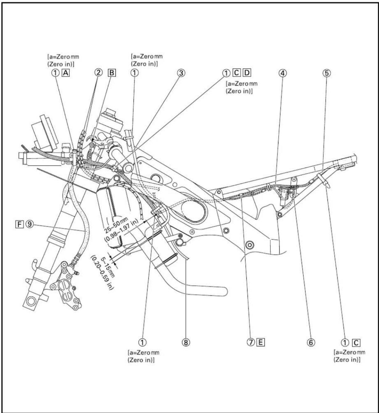
text_image
[a=Zero mm (Zero in)] ① A ② B [a=Zero mm (Zero in)] [1] ③ ① C D [a=Zero mm (Zero in)] ④ ⑤ F ⑨ 25-50mm (0.98-1.97 in) 5-15mm (0.20-0.59 in) ① [a=Zero mm (Zero in)] ⑧ ⑦ E ⑥ ① C [a=Zero mm (Zero in)]CABLE ROUTING DIAGRAM
SPEC

① Tachometer assembly
② Coupler for speed shift
③ CDI unit
④ Voltage regulator
⑤ Servomotor
⑥ Brake hose holder
⑦ Reservoir hose
⑧ Rear brake hose
⑨ Clamp
A Install the tachometer assembly with its figures standing upright.
B Do not make the clamp grip face outside of the chassis.
C Position the reservoir hose with its paint mark upward.
D Make the clamp grip face inside of the chassis.
E Be sure the brake hose is not twisted.
F Do not cut the end of the clamp.
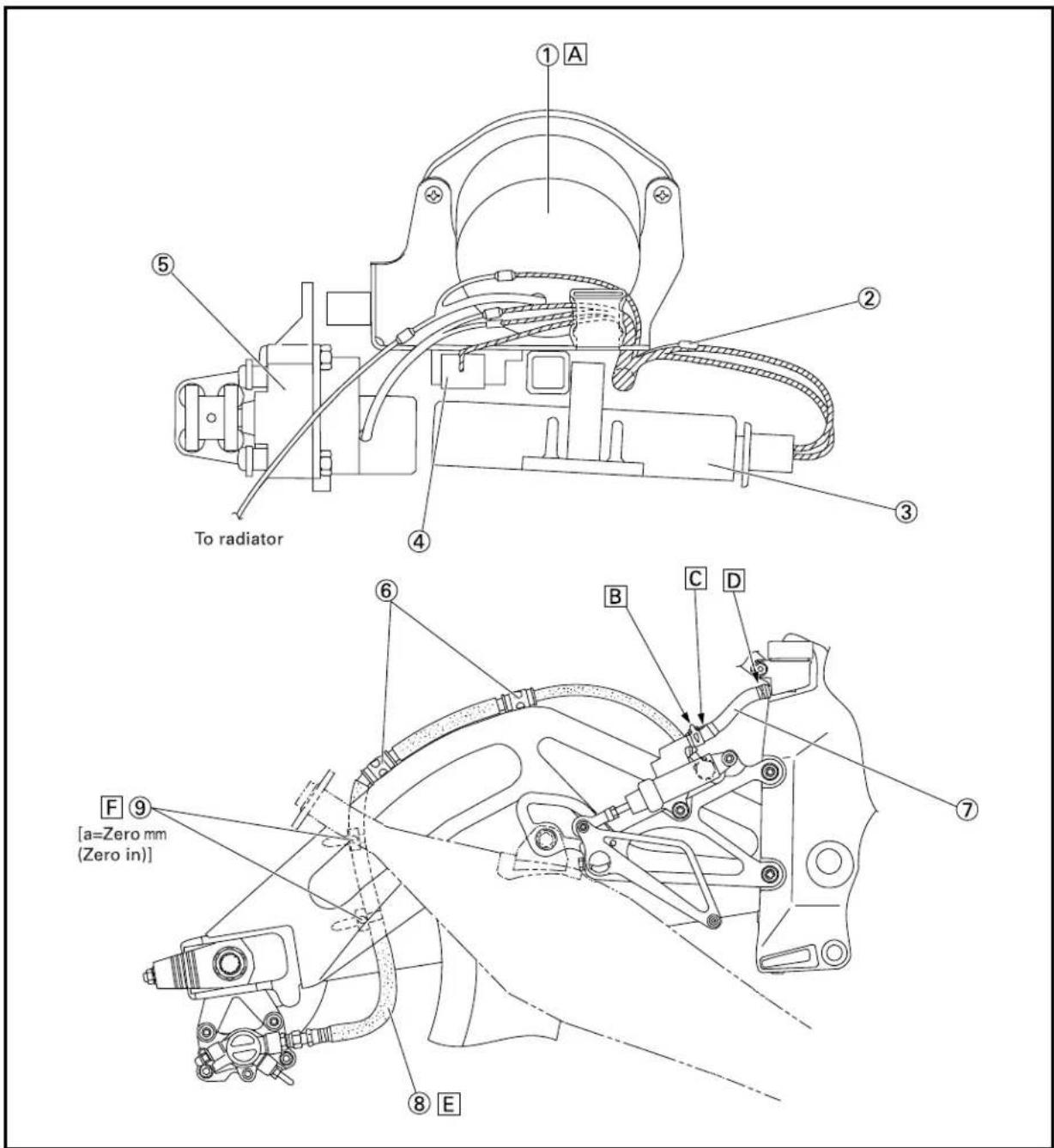
text_image
① A ② ③ To radiator ④ ⑤ ⑥ B C D ⑦ F ⑨ [a=Zero mm (Zero in)] ⑧ EEC300000
REGULAR INSPECTION AND ADJUSTMENTS
EC310070
MAINTENANCE INTERVALS
The following schedule is intended as a general guide to maintenance and lubrication. Bear in mind that such factors as weather, terrain, geographical location, and individual usage will alter the required maintenance and lubrication intervals. If you are a doubt as to what intervals to follow in maintaining and lubricating your machine, consult your Yamaha dealer.
NOTE:
Replace earlier depending on the operating condition.
| Item break- | After in km | Every race 500km | Every 1,000 | As required | Remarks |
| PISTONInspect and cleanReplace ● ● | ● | Inspect crack | |||
| PISTON PIN, SMALL END BEARINGInspect ● ●Replace ● ● | |||||
| PISTON RINGInspect ● ● Check ring Replace ● ● | end gap | ||||
| CYLINDER HEADInspect and clean ● ●Retighten ● ● Check O-ring | Remove carbon | ||||
| CYLINDERInspect and clean ● ●Replace Retighten ● ● | (3,000 km)● | Inspect score marksInspect wear | |||
| YPVSInspect ● ●Retighten ● ● | |||||
| CLUTCHInspect and adjustReplace | ● | ● | plate | Inspect housing, friction plate and spring | |
| TRANSMISSIONReplace oilInspect transmissionReplace bearing | ● | ● | Castrol R30 | ||
| SHIFT FORK, SHIFT CAM, GUIDE BARInspect | Inspect wear | ||||
| ROTOR NUTRetighten | ● | ||||
| MUFFLERInspect ● ● Inspect crackClean | |||||
| CRANKInspect and replace | (1,500 km)● | Inspect jet needle clip groove | |||
| CARBURETORInspect, adjust and clean | ● | ● |

| Item break- | After in km | Every race 5 | Every 500km | Every 1,000 | As required | Remarks |
| SPARK PLUGInspect and clean ● ●Replace ● | ||||||
| PLUG CAPInspect and replace ● ● | (1,500 km) | |||||
| COOLING SYSTEMCheck cooling level and leakage ● ●Check radiator cap operation ●Replace cooling water ● Use soft waterReplace hoses | ● | |||||
| OUTSIDE NUTS AND BOLTSRetighten | ● | ● | Refer to “STARTING AND BREAK-IN” section in the CHAPTER 1. | |||
| OIL PUMP STRAINERClean | ● | ● | ||||
| REED VALVEInspectReplace ● | ● | ● | ||||
| FRAMEClean and inspect | ● | ● | ||||
| FUEL TANK, COCKClean and inspect | ● | ● | ||||
| BRAKESAdjust lever position and pedal positionCheck brake disc surfaceCheck brake fluid level and leakageRetighten brake disc bolts, caliper boltsand master cylinder boltsReplace padsReplace brake fluid | ● | ● | ●● | Every one year | ||
| ● | ● | |||||
| ● | ● | |||||
| ● | ● | |||||
| ● | ● | |||||
| FRONT FORKSInspect and adjustReplace oilReplace oil seal | ● | ● | ● | ● | Suspension oil “01” | |
| REAR SHOCK ABSORBERInspect and adjustLubeRetighten | ● | ● | (After rain race)● Molybdenum disulfide grease | |||
| ● | ● | |||||
| CHAIN GUARDReplace ● | ||||||
| SWINGARMInspect and retighten | ● | ● | ||||
| RELAY ARM, CONNECTING RODInspect and retighten | ● | ● | ||||
| STEERING HEADInspect free play and retightenClean and lubeReplace bearings | ● | ● | ● | ● | Lithium base grease |
| Item break- | After in km | Every race 500km | Every 1,000 | As required | Remarks |
| TIRE, WHEELSInspect air pressure, wheel run-out and ●tire wearInspect bearings ● Replace bearings ●Lubricate ● Lithium base grease | ● | ||||
| DRIVE CHAIN Use chain lubeLubricate, slack, alignmentReplace | ● | ● | ● | Chain slack: 40~50 mm(1.6~2.0 in) | |
| DRIVE, DRIVEN SPROCKETInspect and replace | ●Inspect wear | ||||
| DRIVEN SPROCKET DAMPERInspect and retightenReplace | ● | ● | ● | ||
| THROTTLE, CONTROL CABLECheck routing and connectionLubricate | ●● | ●● | Yamaha cable lube or SAE10W30 motor oil | ||
| BATTERYCheck battery voltageReplace | ● | ● | 12.5V or more● |
EC320010
Before riding for break-in operation, practice or a race, make sure the machine is in good operating condition.
Before using this machine, check the following points.
NOTE:
- The brake disc is coated with a rush inhibitor. Before pre-operation thoroughly remove it using a lacquer thinner.
- For storage, a coolant is used. Before riding the machine remove it with cooling water. Refer to “INFORMATION BEFORE PRE-OPERATION”.
EC321020
GENERAL INSPECTION AND MAINTENANCE
| Item Routine Page | ||
| Cooling water Check that cooling water is filled up to the radiator filler cap. Check the cooling system for leakage. | P3-6~9 | |
| Fuel Check that a fresh mixture of oil and gasoline is filled in the fuel tank. Check the fuel line for leakage. | P1-14 | |
| Transmission oil Check that the oil level is correct. Check the crankcase for leakage. | P3-13~15 | |
| YPVS Check operation. P3-12~13 | ||
| Gear shifter and clutch Check that gears can be shifted correctly in order and that the clutch operates smoothly. | P3-9~10 | |
| Throttle grip/Housing Check that the throttle grip operation and free play are correctly adjusted. Lubricate the throttle grip and housing, if necessary. | P3-10~11 | |
| Brakes | Check the effect of front and rear brake. Check brake disc surface. | P3-17~22 |
| Chain | Check chain slack and alignment. Check that the chain is lubricated properly. | P3-23~25 |
| Wheels | Check for excessive wear, tire pressure and tire wear. | P3-36 |
| Steering | Check that the handlebars can be turned smoothly and have no excessive play. | P3-37~38 |
| Front forks and rear shock absorber | Check that they operate smoothly and there is no oil leakage. | P3-27~35 |
| Cables (wires) | Check that the clutch and throttle cables move smoothly. Check that they are not caught when the handlebars are turned or when the front forks travel up and down. | P3-39 |
| Muffler | Check that the muffler is tightly mounted and has no cracks. | P3-16 |
| Sprocket | Check that the driven sprocket damper is not loose. | P3-22 |
| Lubrication | Check for smooth operation. Lubricate if necessary. | P3-41 |
| Bolts and nuts | Check the chassis and engine for loose bolts and nuts. Check that the locking wire is correct. | P1-19~20 |
| Lead connectors | Check that the CDI magneto, CDI unit, and ignition coil are connected tightly. | P1-5 |
| Battery | Check the battery voltage. | P3-44~46 |
| Cowling | Check that the cowling is tightly mounted and has no cracks in it. Check that it dose not contact other parts by stroking. Check that the screen is clean. | P3-39 |
| Settings | Is the machine set suitably for the condition of the racing course and weather or by taking into account the results of test runs before racing? Are inspection and maintenance completely done? | P7-1~22 |
EC340000
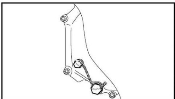
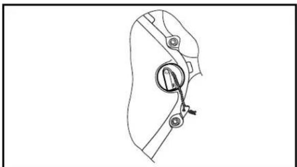
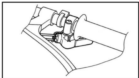
LOCKING WIRE INSTALLATION GUIDE

natural_image
Diagram of a mechanical linkage or rope system with two hexagonal components connected by a chain (no text or symbols)Bolt to bolt

natural_image
Simple line drawing of a hexagonal prism with a rope wrapped around it (no text or symbols)Bolt
natural_image
Technical line drawing of a mechanical component with mounting holes and a central shaft (no text or symbols)YPVS pulley
natural_image
Technical line drawing of a mechanical lever assembly (no text or symbols)Throttle cable adjuster
natural_image
Technical line drawing of a mechanical linkage component (no text or symbols)Oil drain bolt and check bolt

natural_image
Technical line drawing of a mechanical component with a bolt and nut (no text or symbols)Tank rail drain bolt
natural_image
Line drawing of a mechanical component with a central circular feature and two circular ends (no text or symbols)Oil filler cap
natural_image
Technical line drawing of a mechanical assembly with no visible text or symbolsStarter cable
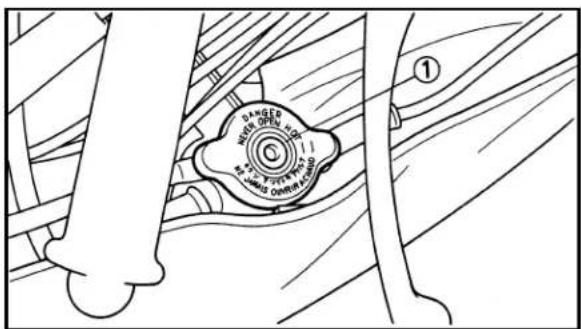
ENGINE/COOLING WATER LEVEL INSPECTION/ COOLING WATER REPLACEMENT
INSP ADJ

text_image
DANGER OPEN HOLD OPEN ①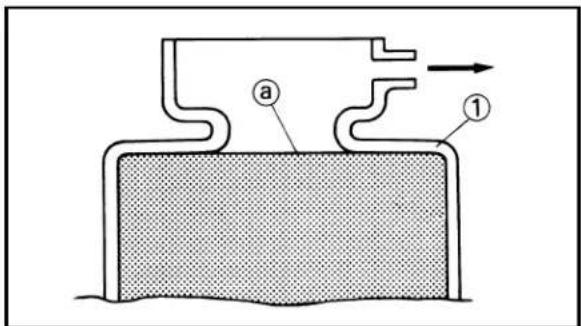
text_image
Diagram of a mechanical or fluidic device with labeled parts (a, 1) and directional arrow indicating flow or movement.EC350011
ENGINE
CAUTION:
• The cooling system is filled with coolant at the factory to prevent rusting. Be sure to replace coolant with soft water before riding.
• Take care so that coolant does not splash on painted surfaces. If it splashes, wash it away with water.
EC352000
COOLING WATER LEVEL INSPECTION
WARNING
Do not remove the radiator cap ①, drain bolt and hoses when the engine and radiator are hot. Scalding hot fluid and steam may be blown out under pressure, which could cause serious injury.
When the engine has cooled, place a thick towel over the radiator cap, slowly rotate the cap counterclockwise to the detent. This procedure allows any residual pressure to escape. When the hissing sound has stopped, press down on the cap while turning counterclockwise and remove it.
CAUTION:
Hard water or salt water is harmful to the engine parts. You may use distilled water, if you can't get soft water.
- Place the machine on a level place, and hold it in an upright position.
- Remove:
- Radiator cap
- Check:
- Cooling water level ⓐ
Cooling water level low → Add cooling water.
① Radiator
EC354013
COOLING WATER REPLACEMENT
WARNING
Do not remove the radiator cap when the engine is hot.
- Remove the lower cowl.
- Place a container under the radiator hose.
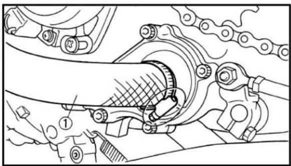
natural_image
Mechanical assembly diagram showing a linkage mechanism with no visible text or symbols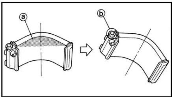
text_image
Technical diagram showing two mechanical component views labeled (a) and (b), with transformation indicated by an arrow.
text_image
Technical diagram showing mechanical assembly with labeled components and numbered parts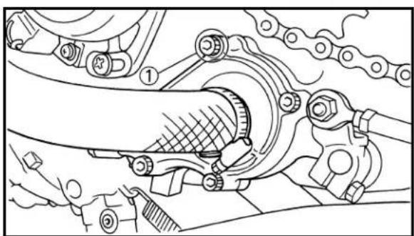
natural_image
Mechanical assembly diagram showing a linkage mechanism with no visible text or symbols- Disconnect:
- Radiator hose 2 ①
- Remove:
- Radiator cap
Drain the cooling water completely.
- Clean:
- Cooling system
Thoroughly flush the cooling system with clean tap water.
- Connect:
- Radiator hose 2
2 Nm (0.2 m·kg, 1.4 ft·lb)
- Fill:
- Radiator
- Engine
To specified level.

Recommended cooling water: Soft water
Cooling water capacity:
1.4 L (1.23 Imp qt, 1.48 US qt)
CAUTION:
- When filling the radiator with anti-freeze, tilt the motorcycle so that the filler hole ⑥ is at the highest position. If the radiator is positioned upright, air ④ is difficult to escape which may result in excessive engine heating.
-
Hard water or salt water is harmful to the engine parts. You may use distilled water, if you can't get soft water.
-
Remove:
• Air bleeding bolt (right cylinder) ①
Bleeding the air until coming out the cooling water.
- Install:
• Copper washer New
• Air bleeding bolt (right cylinder)
12 Nm (1.2 m·kg, 8.7 ft·lb)
- Remove:
• Air bleeding bolt (water pump) ①
Bleeding the air until coming out the cooling water.
- Install:
• Copper washer New
• Air bleeding bolt (water pump)
11 Nm (1.1 m·kg, 8.0 ft·lb)
RADIATOR CAP INSPECTION/ RADIATOR CAP OPENING PRESSURE INSPECTION

12.Fill:
- Radiator
- Engine
To specified level.
- Install:
- Radiator cap
Start the engine and warm it up for a several minute.
14.Check:
- Cooling water level
Cooling water level low → Add cooling water.
- Install the lower cowl.
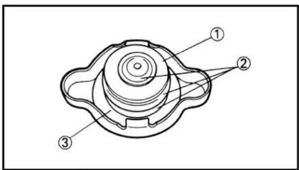
text_image
Technical diagram of a mechanical component with numbered parts labeled ①, ②, and ③.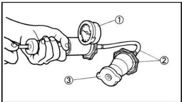
text_image
Technical diagram showing a hand holding a valve connected to a connector with labeled parts ①, ②, and ③.EC355000
RADIATOR CAP INSPECTION
-
Inspect:
-
Seal (radiator cap) ①
- Valve and valve seat ②
Crack/Damage → Replace.
Exist fur deposits ③ → Clean or replace.
EC356002
RADIATOR CAP OPENING PRESSURE INSPECTION
- Attach:
- Radiator cap tester ① and adapter ②

Radiator cap tester:
YU-24460-01/90890-01325
Adapter:
YU-33984/90890-01352
NOTE:
Apply water on the radiator cap seal.
③ Radiator cap
- Apply the specified pressure.

Radiator cap opening pressure:
95\~125 kPa (0.95\~1.25 kg/cm²,
13.5\~17.8 psi)
- Inspect:
- Pressure
Impossible to maintain the specified pressure for 10 seconds → Replace.
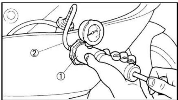
text_image
Technical diagram showing car engine valve assembly with labeled parts ① and ②EC357003
COOLING SYSTEM INSPECTION
- Inspect:
- Coolant level
- Attach:
- Radiator cap tester ① and adapter ②

Radiator cap tester: YU-24460-01/90890-01325
Adapter: YU-33984/90890-01352
- Apply the specified pressure.

Standard pressure: 180 kPa (1.8 kg/cm², 25.6 psi)
NOTE:
- Do not apply pressure more than specified pressure.
- Radiator should be filled fully.
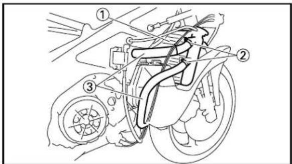
text_image
Technical diagram of a vehicle's internal components with numbered parts labeled ①, ②, and ③-
Inspect:
-
Pressure
Impossible to maintain the specified pressure for 10 seconds → Repair. - Radiator ①
- Radiator hose joint ②
Coolant leakage → Repair or replace. - Radiator hose ③
Swelling → Replace.

natural_image
Technical line drawing of a mechanical clutch assembly (no text or symbols)EC358000
CLUTCH CARE
NOTE:
This machine is equipped with a dry type clutch. Be sure to clean with solvent or replace if grease or oil contacts either clutch or friction plates.
CLUTCH ADJUSTMENT/ THROTTLE CABLE ADJUSTMENT


text_image
Technical diagram showing mechanical assembly with labeled parts (a and ②) and directional arrows indicating motion or force.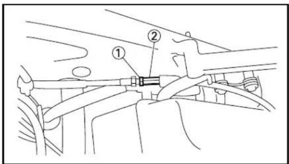
text_image
Technical diagram showing mechanical assembly with labeled parts ① and ②
natural_image
Technical line drawing of a mechanical assembly with labeled component 'a' (no text or symbols beyond label)EC359001 CLUTCH ADJUSTMENT
1. Check:
- Clutch lever free play ⓐ Out of specification → Adjust.

Clutch lever free play ⓐ: 2\~3 mm (0.08\~0.12 in)
2. Adjust:
- Clutch lever free play
Clutch lever free play adjustment steps:
- Loosen the locknut ①.
- Turn the adjuster ② until free play ④ within the specified limits.
- Tighten the locknut.
NOTE:
After adjustment, check proper operation of clutch lever.
EC35A040
THROTTLE CABLE ADJUSTMENT
1. Check:
- Throttle grip free play ⓐ Out of specification → Adjust.

Throttle grip free play ⓐ: 2\~4 mm (0.08\~0.16 in)
2. Remove:
- Lower cowl
- Fuel tank
- Induction guide (right cylinder)

natural_image
Technical line drawing of a mechanical assembly with no visible text or symbols- Loosen the screw (right carburetor joint clamp), then take out the carburetor ①.

text_image
Technical diagram of a mechanical assembly with numbered components, likely illustrating a valve or actuator mechanism.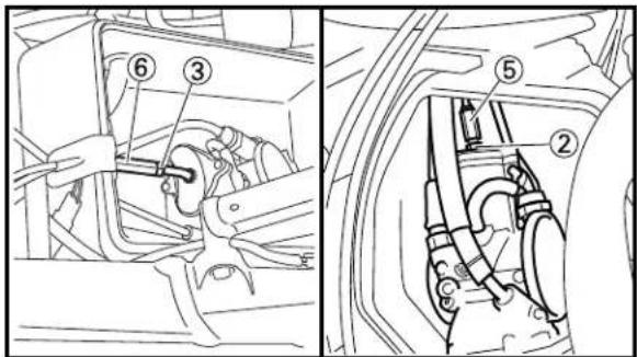
text_image
Technical diagram showing labeled mechanical components in two views: one with a hand holding a tool, the other with wiring and tubing.
natural_image
Line drawing of a person adjusting or working on an engine component (no text or symbols visible)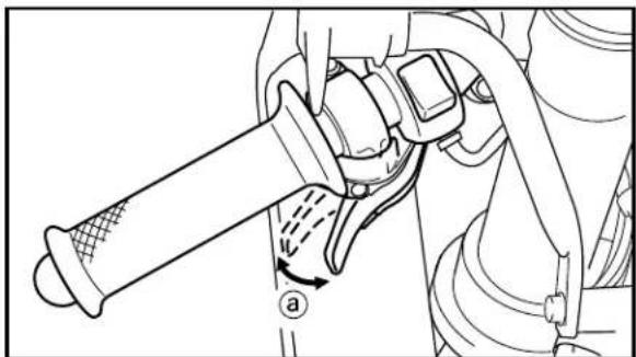
natural_image
Mechanical assembly diagram showing a lever mechanism with no visible text or symbols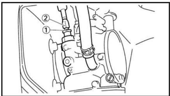
text_image
Technical diagram showing mechanical assembly with numbered components labeled ① and ②4. Adjust:
- Throttle grip free play
Throttle grip free play adjustment steps:
- Loosen the locknuts ①, ②, ③.
- Turn the adjusters ④, ⑤, ⑥ fully in.
- Turn out the right carburetor adjuster ⑤ until the specified free play is obtained.
- Tighten the right carburetor locknut ②.
- Turn out the left carburetor adjuster ⑥ until the left throttle valve moves together with the right throttle valve.
NOTE:
- When adjusting left throttle cable, watch the right throttle valve and touch the left throttle valve.
• After adjusting the throttle cables, open the throttle grip and check that both throttle valves are completely open. - Tighten the left carburetor locknut ③.
- Tighten the locknuts ①.
WARNING
After adjusting, turn the handlebar to right and left and make sure that the engine idling dose not run faster.
EC35B002
STARTER CABLE ADJUSTMENT
1. Check:
- Starter lever free play ⓐ
Out of specification → Adjust.

Starter lever free play ⓐ: 5\~10 mm (0.20\~0.39 in)
2. Adjust:
- Starter lever free play
Starter lever free play adjustment steps:
- Loosen the locknuts ①.
- Turn the adjusters ② until the specified free play is obtained.
- Tighten the locknuts.

text_image
Technical diagram of a mechanical assembly with labeled parts and directional arrows indicating motion or movement.EC35D012
YPVS OPEN SIDE CABLE ADJUSTMENT
-
Disconnect the fuel pump coupler to prevent the fuel pump operation.
-
Check:
- YPVS open side cable free play ⓐ
Checking steps:
- Move the main switch to "RUN".
• The servomotor will be fully opened.
NOTE:
After the main switch is moved to "RUN", the servomotor will be operated as follows.
- The servomotor will be fully closed about 1 second.
- And then, it will be kept fully opened.
- Check the free play ⓐ for the YPVS open side cables ①.
Out of specification → Adjust.

YPVS open side cable free play ⓐ:
2\~3 mm (0.08\~0.12 in)

text_image
Technical diagram of a mechanical assembly with numbered components, likely for assembly or maintenance instructions.- Adjust:
- YPVS open side cable free play
Adjusting steps:
• Fully open the servomotor.
- Loosen the locknuts ①.
- Turn the adjusters ② until the specified free play is obtained.
- Tighten the locknuts.
YPVS CLOSE SIDE CABLE ADJUSTMENT/YPVS COMPONENTS RETIGHTENING/TRANSMISSION OIL LEVEL CHECK


text_image
Technical diagram of a mechanical assembly with labeled parts ① and ②, showing hoses and components.EC35E011 YPVS CLOSE SIDE CABLE ADJUSTMENT
-
Disconnect the fuel pump coupler to prevent the fuel pump operation.
-
Check:
- YPVS close side cable free play ⓐ
Checking steps:
- Move the main switch to "RUN".
- The servomotor will be fully closed about 1 second.
- During this 1 second, move the main switch to "OFF".
• The servomotor will be kept fully closed. - Check the free play ④ for the YPVS close side cables ①.
Out of specification → Adjust.

YPVS close side cable free play ①: 2\~3 mm (0.08\~0.12 in)
- Adjust:
- YPVS close side cable free play
Adjusting steps:
• Fully close the servomotor.
- Loosen the locknuts ①.
- Turn the adjusters ② until the specified free play is obtained.
- Tighten the locknuts.

text_image
Technical diagram of a mechanical assembly with numbered components, likely for assembly or maintenance instructions.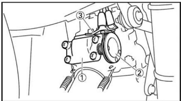
text_image
Technical diagram of a mechanical assembly with numbered components, likely for vehicle maintenance or repair.EC35F000 YPVS COMPONENTS RETIGHTENING
NOTE:
Before riding the machine, retighten all YPVS components.
- Retighten:
| • Valve cover 1 | 4 Nm (0.4 m·kg, 2.9 ft·lb) |
| • Pulley 2 | 4 Nm (0.4 m·kg, 2.9 ft·lb) |
| • Cable stay 3 | 7 Nm (0.7 m·kg, 5.1 ft·lb) |
EC35H030 TRANSMISSION OIL LEVEL CHECK
- Start the engine, warm it up for several minutes and wait for five minutes.
- Place the machine on a level place and hold it up on upright position by placing the suitable stand.
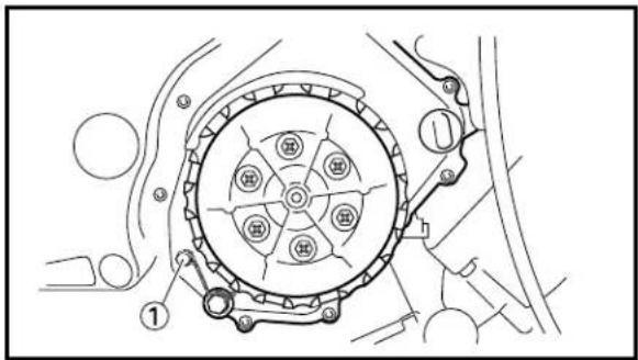
text_image
Technical diagram of a mechanical assembly with numbered components and labeled parts3. Check:
• Transmission oil level
Transmission oil level checking steps:
- Remove the oil check bolt ①.
- Inspect the oil level.
NOTE:
Be sure the machine is positioned straight up when inspecting the oil level.
WARNING
Never attempt to remove the checking bolt just after high speed operation. The heated oil could spout out, causing danger. Wait until the oil cools down.
Oil flows out Oil level is correct.
Oil does not flow out → Oil level is low Add transmission oil until oil flows out.

Recommended oil: Castrol R30
- Inspect the gasket (oil check bolt), replace if damaged.
- Tighten the oil check bolt.

Oil check bolt: 9 Nm (0.9 m·kg, 6.5 ft·lb)
EC35K021
TRANSMISSION OIL REPLACEMENT
- Start the engine and warm it up for several minutes and wait for five minutes.
- Place the machine on a level place and hold it on upright position by placing the suitable stand.
- Place a suitable container under the engine.
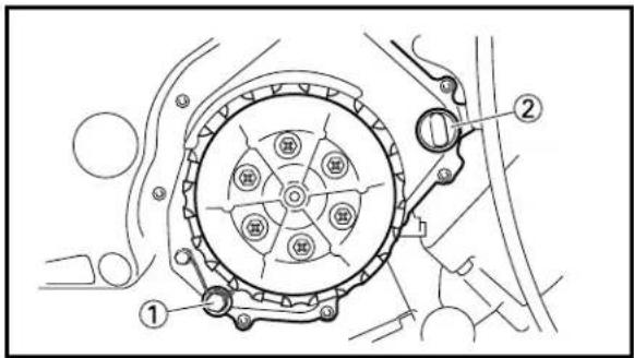
text_image
Technical diagram of a mechanical assembly with numbered components and labeled parts-
Remove:
-
Oil drain bolt ①
- Oil filler cap ②
Drain the transmission oil.
- Install:
• Copper washer New
- Oil drain bolt ①
23 Nm (2.3 m·kg, 17 ft·lb)
NOTE:
After tightening the oil drain bolt to specified torque, lock it using a wire.
- Fill:
- Transmission oil

Recommended oil:
Castrol R30
Oil capacity
(periodic oil change):
0.50 L (0.44 Imp qt, 0.53 US qt)
- Check:
- Oil leakage
- Check:
• Transmission oil level - Install:
- Oil filler cap ②

natural_image
Technical line drawing of a mechanical assembly with no visible text or symbolsEC35L002
PILOT AIR SCREW ADJUSTMENT
- Adjust:
- Pilot air screw ①
Adjustment steps:
- Screw in the pilot air screw until it is lightly seated.
- Back out by the specified number of turns.

Pilot air screw:
1-1/2 turns out

text_image
Technical diagram showing a pipe fitting with two circular components labeled ① and numbered marker ①
natural_image
Technical line drawing of a cylindrical mechanical component with mounting holes and a flanged end (no text or symbols)EC35P010
MUFFLER INSPECTION
- Inspect:
- O-ring ①
Damage → Replace.
EC35Q001
SILENCER INSPECTION
- Inspect:
- Silencer
Inside of silencer loose → Repair.
Silencer repair steps:
- Drill the silencer for riveting.
- Rivet the silencer using the rivet.
NOTE:
Rivet the silencer in a different area than previously riveted.
EC360000
CHASSIS
EC361002
BRAKE SYSTEM AIR BLEEDING
WARNING
Bleed the brake system if:
• The system has been disassembled.
• A brake hose has been loosened or removed.
• The brake fluid is very low.
• The brake operation is faulty.
A dangerous loss of braking performance may occur if the brake system is not properly bleed.

text_image
A ① ②
text_image
Technical diagram of a mechanical assembly with labeled parts ① and ②
text_image
Technical diagram showing labeled mechanical components with numbered parts, likely illustrating a linkage or assembly.- Remove:
- Reservoir tank cap
-
Diaphragm
-
Bleed:
- Brake fluid
A Front
B Rear
Air bleeding steps:
a. Add proper brake fluid to the reservoir.
b. Install the diaphragm. Be careful not to spill any fluid or allow the reservoir to overflow.
c. Connect the clear plastic tube ② tightly to the caliper bleed screw ①.
d. Place the other end of the tube into a container.
e. Slowly apply the brake lever or pedal several times.
f. Pull the lever in or push down on the pedal. Hold the lever or pedal in position.
g. Loosen the bleed screw and allow the lever or pedal to travel towards its limit.
h. Tighten the bleed screw when the lever or pedal limit has been reached; then release the lever or pedal.

Bleed screw: 6 Nm (0.6 m·kg, 4.3 ft·lb)
i. Repeat steps (e) to (h) until of the air bubbles have been removed from the system.
If bleeding is difficult, it may be necessary to let the brake fluid system stabilize for a few hours. Repeat the bleeding procedure when the tiny bubbles in the system have disappeared.
j. Add brake fluid to the level line on the reservoir.
WARNING
Check the operation of the brake after bleeding the brake system.
3. Install:
- Diaphragm
- Reservoir tank cap
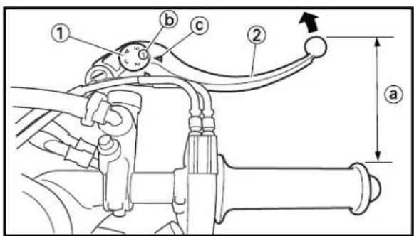
text_image
Technical diagram of a mechanical assembly with labeled parts and dimension annotationsEC363020
- Turn the adjuster ① while pushing the brake lever ② forward until the desired lever position is obtained.
Closer → Turn the adjuster to a larger number.
Farther → Turn the adjuster to a smaller number.
NOTE:
Align the number ⓑ on the adjuster with the mark Ⓒ on the brake lever.
text_image
Technical diagram of a vehicle suspension system with labeled components and motion indicatorsEC364011
Out of specification → Adjust.

Brake pedal height ⓐ:
148\~152 mm (5.8\~6.0 in)
FRONT BRAKE PAD INSPECTION AND REPLACEMENT
INSP ADJ


text_image
Technical diagram of a mechanical linkage system with numbered components
text_image
Technical diagram showing mechanical assembly with labeled parts and a magnified inset showing a cross-section detail.
text_image
Technical diagram of a mechanical assembly with numbered components, likely illustrating a vehicle or mechanical assembly.
text_image
Technical diagram of a hand holding a mechanical component with numbered parts labeled 3 through 6.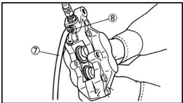
text_image
Technical diagram of a mechanical assembly with numbered components labeled ⑦, ⑧, and ⑨2. Adjust:
- Brake pedal height
Pedal height adjustment steps:
- Loosen the locknut ①.
- Turn the adjusting nut ② until the pedal height is within specified height.
- Tighten the locknut.
EC365050
FRONT BRAKE PAD INSPECTION AND REPLACEMENT
1. Inspect:
- Brake pad thickness ⓐ
Out of specification → Replace as a set.

Brake pad thickness ⓐ:
Standard
5.3 mm (0.21 in) 1.0 mm (0.04 in)
2. Replace:
- Brake pad
Brake pad replacement steps:
- Loosen the pad pin ① and remove the caliper ②.
- Remove the cotter pin ③, pad pin ④, pad support ⑤ and brake pads ⑥.
- Connect the transparent hose ⑦ to the bleed screw ⑧ and place the suitable container under its end.
- Loosen the bleed screw and push the caliper piston in.
CAUTION:
Do not reuse the drained brake fluid.
- Tighten the bleed screw.

Bleed screw:
6 Nm (0.6 m·kg, 4.3 ft·lb)

natural_image
Line drawing of a hand using a tool to adjust or install a mechanical component (no text or symbols visible)
text_image
Technical diagram of a hand holding a mechanical component with numbered parts labeled 10, 11, and 12.
text_image
Technical diagram of a mechanical assembly with numbered components labeled 13, 14, and 15
text_image
Technical diagram showing mechanical assembly with labeled parts and dimension annotations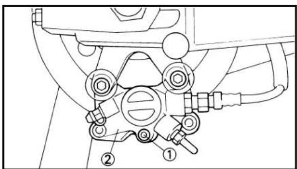
text_image
Technical diagram of a mechanical assembly with numbered components, likely for assembly or maintenance instructions.• Install the brake pads ⑨, pad support ⑩, pad pin ⑪ and cotter pin ⑫.
NOTE:
- Always use a new cotter pin.
- Temporarily tighten the pad pin at this point.
• Install the caliper ⑬ and tighten the pad pin ⑭.

Bolt (caliper): 35 Nm (3.5 m·kg, 25 ft·lb)
Pad pin: 18 Nm (1.8 m·kg, 13 ft·lb)
3. Inspect:
- Brake fluid level Refer to "BRAKE FLUID LEVEL INSPECTION" section.
4. Check:
- Brake lever operation A softly or spongy feeling → Bleed brake system. Refer to “BRAKE SYSTEM AIR BLEEDING” section.
EC366031 REAR BRAKE PAD INSPECTION AND REPLACEMENT
1. Inspect:
- Brake pad thickness ⓐ Out of specification → Replace as a set.

Brake pad thickness ⓐ:
Standard
2. Replace:
- Brake pad
Brake pad replacement steps: - Loosen the pad pin ① and remove the caliper ②.
NOTE:____ Before removing the caliper from the swingarm, loosen the pad pin.

text_image
Technical diagram of a mechanical device with numbered components for identification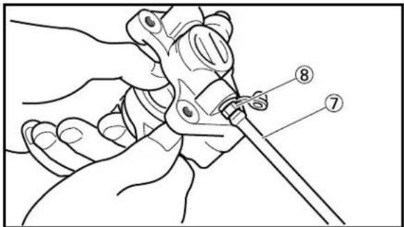
text_image
Technical diagram showing a hand holding a tool with labeled parts 7 and 8
text_image
Technical diagram of a mechanical or electrical component with numbered parts labeled ⑨ to ⑪
text_image
Technical diagram of a mechanical assembly with numbered components labeled 13 and 14- Remove the cotter pin ③, pad pin ④, pad support ⑤ and brake pads ⑥.
- Connect the transparent hose ⑦ to the bleed screw ⑧ and place the suitable container under its end.
- Loosen the bleed screw and push the caliper piston in.
CAUTION:
Do not reuse the drained brake fluid.
- Tighten the bleed screw.

Bleed screw: 6 Nm (0.6 m·kg, 4.3 ft·lb)
• Install the brake pads ⑨, pad support ⑩, pad pin ⑪ and cotter pin ⑫.
NOTE:
• Always use a new cotter pin.
- Temporarily tighten the pad pin at this point.
• Install the caliper ⑬ and tighten the pad pin ⑭.

Bolt (caliper): 23 Nm (2.3 m·kg, 17 ft·lb)
Pad pin: 18 Nm (1.8 m·kg, 13 ft·lb)
3. Inspect:
- Brake fluid level Refer to "BRAKE FLUID LEVEL INSPECTION" section.
4. Check:
- Brake pedal operation A softly or spongy feeling → Bleed brake system. Refer to "BRAKE SYSTEM AIR BLEEDING" section.

text_image
A UPPER a LOWER B UPPER a LOWEREC367001
- Place the master cylinder so that its top is in a horizontal position.
- Inspect:
- Brake fluid level
Fluid at lower level → Fill up.
① Lower level
A Front
B Rear

Recommended brake fluid: DOT #4
WARNING
- Use only designated quality brake fluid to avoid poor brake performance.
- Refill with same type and brand of brake fluid; mixing fluids could result in poor brake performance.
- Be sure that water or other contaminants do not enter master cylinder when refilling.
- Clean up spilled fluid immediately to avoid erosion of painted surfaces or plastic parts.

text_image
aEC368011
SPROCKETS INSPECTION
- Inspect:
- Sprocket teeth ⓐ
Excessive wear → Replace.
NOTE:
Replace the drive, driven sprockets and drive chain as a set.
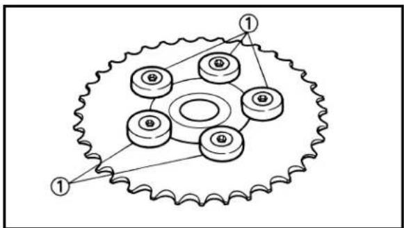
text_image
Diagram of a gear mechanism with labeled components and connection points- Inspect:
- Sprocket damper ①
Wear/Damage → Replace.
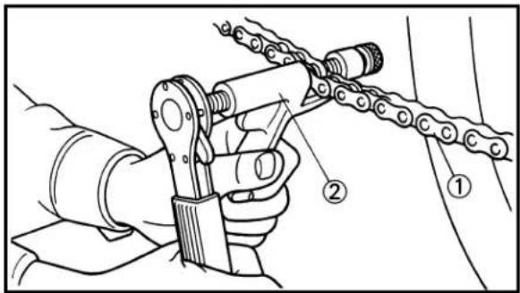
text_image
Technical diagram showing a hand operating a chain link mechanism with labeled parts ① and ②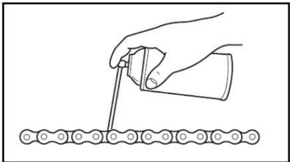
natural_image
Illustration of a hand pouring liquid into a container onto a chain (no text or symbols)
natural_image
Technical line drawing of a mechanical assembly with two identical components and mounting brackets (no text or symbols)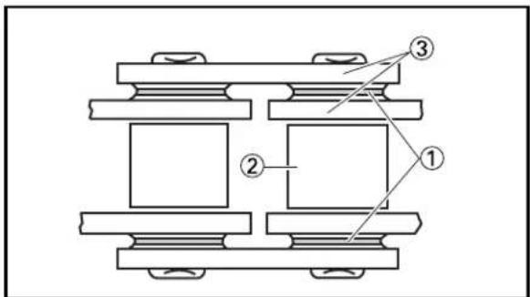
text_image
Technical diagram of a mechanical assembly with numbered components labeled ①, ②, and ③.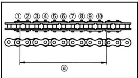
text_image
① ② ③ ④ ⑤ ⑥ ⑦ ⑧ ⑨ ⑩ aEC369040
DRIVE CHAIN INSPECTION
- Remove:
- Drive chain ①
NOTE:
Remove the drive chain using a chain cutter ②.
- Clean:
- Drive chain
Brush off as much dirt as possible. Then clean the chain using the chain cleaner.
CAUTION:
This machine has a drive chain with small rubber O-rings ① between the chain plates. Steam cleaning, high-pressure washes, certain solvent and kerosene can damage these O-rings.
- Inspect:
- O-rings ① (drive chain)
Damage → Replace drive chain.
- Rollers ②
- Side plates ③
Damage/Wear → Replace drive chain.
- Measure:
- Drive chain length (10 links) @
Out of specification → Replace.

Drive chain length (10 links): Limit: 150.1 mm (5.909 in)

text_image
a a a
text_image
New ① ② ③ New ④ B B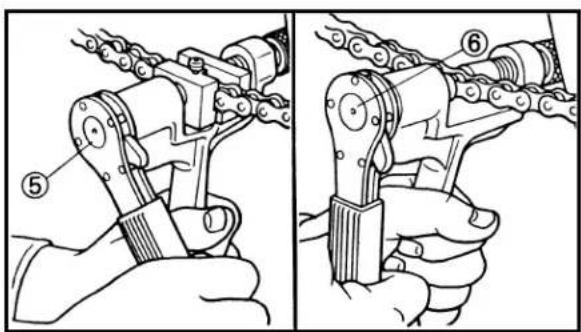
natural_image
Illustration of two manual hand-punching gears, showing different mechanical configurations (no text or symbols present)
natural_image
Diagram of a hand using a tool to interact with a chain and gear mechanism (no text or symbols)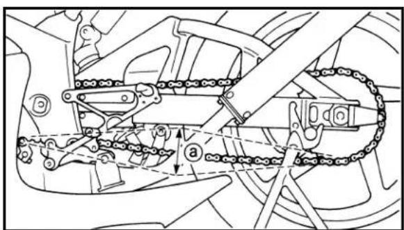
natural_image
Mechanical assembly diagram showing chain links and gear components (no text or labels)5. Check:
- Drive chain stiffness ⓐ
Clean and oil the chain and hold as illustrated.
Stiff → Replace drive chain.
6. Install:
- Chain joint ① New
- O-ring ②
- Drive chain ③
NOTE:
When installing the drive chain, apply the lithium soap base grease on the chain joint and O-rings.
7. Install:
- Link plate ④ New
NOTE:
- Press the link plate onto the chain joint using a chain rivetter ⑤.
- Rivet the end of the chain joint using a chain rivetter ⑥.
• After rivetting the chain joint, make sure its movement is smooth.
8. Lubricate:
- Drive chain

Drive chain lubricant: SAE 30\~50W motor oil or chain lubricants suitable for "O-ring" chains
EC36A042
DRIVE CHAIN SLACK ADJUSTMENT
- Hold the machine on upright position by placing the suitable stand.
2. Check:
- Drive chain slack ⓐ Out of specification → Adjust.

Drive chain slack: 40\~50 mm (1.6\~2.0 in)
NOTE:
Before checking and/or adjusting, rotate the rear wheel through several revolutions and check the slack several times to find the tightest point. Check and/or adjust chain slack with rear wheel in this "tight chain" position.
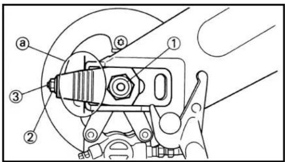
text_image
Technical diagram of a mechanical assembly with numbered components labeled ①, ②, ③, and ④.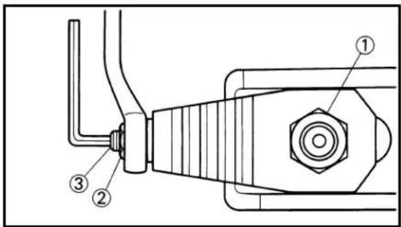
text_image
Technical diagram of a mechanical assembly with numbered components labeled ①, ②, and ③.3. Adjust:
- Drive chain slack
| Drive chain slack adjustment steps:Loosen the axle nut 1 and locknuts 2.Adjust chain slack by turning the adjusters 3. | |
| To tighten → Turn adjuster 3 counterclockwise.To loosen → Turn adjuster 3 clockwise. | |
| Turn each adjuster exactly the same amount to maintain correct axle alignment.(There are marks a on each side of chain puller alignment.)NOTE:Turn the adjuster so that the chain is in line with the sprocket, as viewed from the rear. | |
| CAUTION:Too small chain slack will overload the engine and other vital parts; keep the slack within the specified limits.Tighten the axle nut while pushing down the drive chain. | |
 | Axle nut:80 Nm (8.0 m·kg, 58 ft·lb) |
| Turn out the adjusters to the specified torque. | |
 | Adjuster:2 Nm (0.2 m·kg, 1.4 ft·lb) |
| Tighten the locknuts. | |
 | Locknut:16 Nm (1.6 m·kg, 11 ft·lb) |
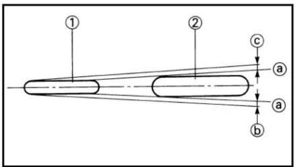
text_image
① ② c a a b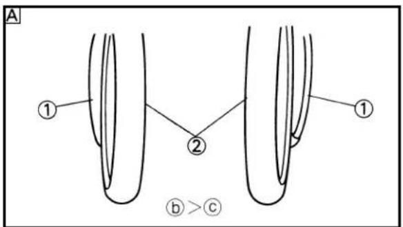
text_image
A ① ② ① b > c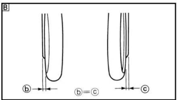
text_image
B b ①=② c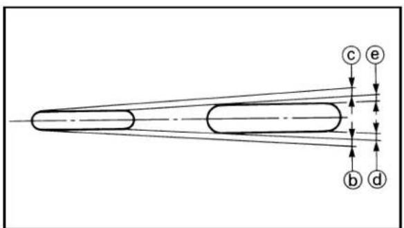
text_image
c e b d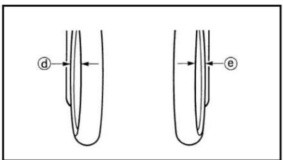
text_image
d eEC36B000
WHEEL ALIGNMENT ADJUSTMENT
-
Remove:
-
Lower cowl
- Place the machine on a level place and hold it up on upright position.
- Sit 1\~2 m (3.3\~6.6 ft) behind the machine and look at both sides of the wheels below the rear wheel axle.
- Turn the handlebar left and right to make the front wheel straight.
NOTE:
- To make the front wheel straight, provide ⑥ and ⑤ with the same distance as seen along the extension of the line ④ connecting the rear end of the front wheel ① and the front end of the rear wheel ②.
- Figure A shows that the front wheel is turned clockwise (b > c).
-
Figure B shows that the front wheel is straight (b = c).
-
Check:
- Wheel alignment
With the front wheel straight (⑥ = ⓒ), check whether the distances ⓐ and ⓔ are equal.
If not → Adjust.
FRONT FORK INSPECTION/ FRONT FORK TOP END ADJUSTMENT


text_image
C b d c e6. Adjust:
- Wheel alignment
Turn the chain puller adjuster while paying attention to the drive chain slack and make adjustment while moving the rear wheel.
NOTE:
- Figure C shows that the wheel alignment has been correctly made (b = c and d = e).
• After the adjustment, record the difference in the graduation between the left and right chain pullers as it will provide convenience in your future similar adjustment.
7. Install:
- Lower cowl
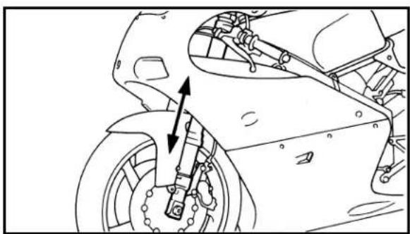
natural_image
Technical line drawing of a motorcycle's wheel assembly with mounting bracket and brake lever (no text or symbols)EC36C000
FRONT FORK INSPECTION
- Inspect:
- Front fork smooth action Operate the front brake and stroke the front fork. Unsmooth action/oil leakage → Repair or replace.
EC36E021
FRONT FORK TOP END ADJUSTMENT
-
Hold the machine on upright position by placing the suitable stand.
-
Remove:
-
Cowling
- Induction guide (left cylinder)
- Front wheel
- Front fender

natural_image
Technical line drawing of mechanical components, showing assembly and assembly details (no text or symbols)3. Adjust:
- Front fork top end
Adjustment steps:
- Loosen the pinch bolts (handlebar and steering damper stay).
- Loosen the pinch bolts (handle crown and under bracket).

natural_image
Technical line drawing of a mechanical device with no visible text or symbols
natural_image
Technical line drawing of an engine assembly showing hoses and brackets (no text or labels)
text_image
Technical schematic diagram of a mechanical device with labeled components and dimensional annotations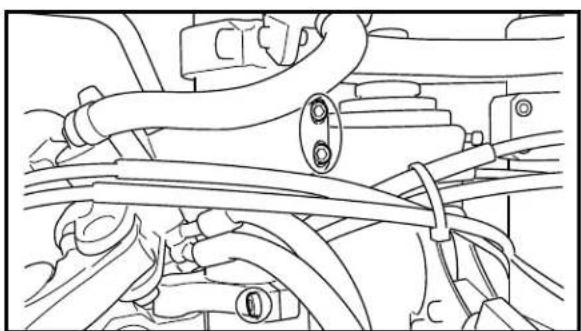
natural_image
Technical line drawing of automotive engine components including hoses and valves (no text or labels)| • Adjust the front fork top end a. | |
 Front fork top end a: Front fork top end a: | |
| Standard | Extent of adjustment |
| 13 mm (0.51 in) | Zero~13 mm(Zero~0.51 in) |
| CAUTION:Never attempt to install the front fork beyond the maximum or minimum setting. | |
| WARNINGAlways adjust each front fork to the same setting. Uneven adjustment can cause poor handling and loss of stability.Tighten the pinch bolts (handle crown and under bracket). | |
| Pinch bolt (handle crown):20 Nm (2.0 m·kg, 14 ft·lb)Pinch bolt (under bracket):23 Nm (2.3 m·kg, 17 ft·lb) | |
| CAUTION:Tighten the under bracket to specified torque. If torqued too much, it may cause the front fork to malfunction.Adjust the handlebar position b and steering damper stay position c. | |
| Handlebar position b:9 mm (0.35 in)Steering damper stay position c:73 mm (2.87 in) | |
| • Tighten the pinch bolts (handlebar and steering damper stay). | |
| Pinch bolt (handlebar):7 Nm (0.7 m·kg, 5.1 ft·lb)Pinch bolt (steering damper stay):10 Nm (1.0 m·kg, 7.2 ft·lb) | |
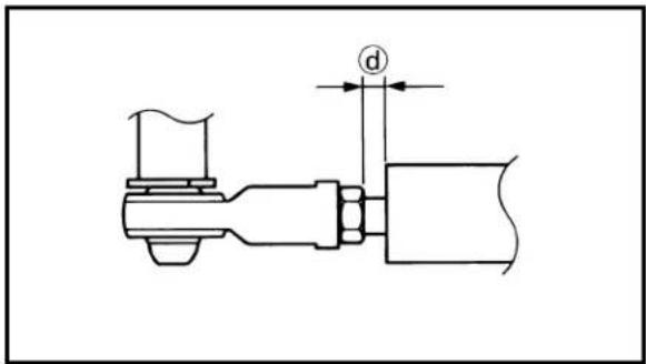
text_image
dCAUTION:
Tighten the pinch bolts to specified torque. If torqued too much, it may cause the front fork to malfunction.
NOTE:
Adjust the installation angle of the steering damper stay so that the dimension ⓓ is between 3 mm (0.12 in) and 5 mm (0.20 in) when the handlebar is turned fully to the right.

natural_image
Technical line drawing of an engine assembly with rotating components (no text or symbols)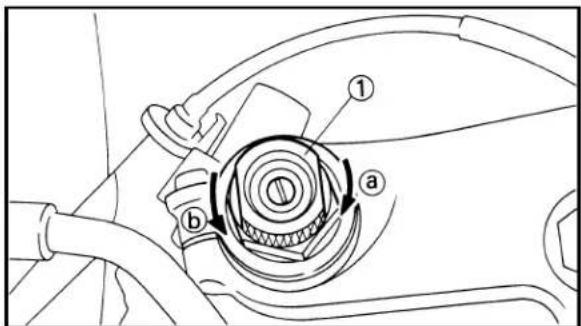
text_image
Technical diagram of a mechanical component with labeled parts ① and ②, showing internal structure and directional arrows.4. Check:
- Steering smooth action Turn the handlebar to make sure no parts are being contacted with others. Contact → Repair.
5. Install:
- Front fender
- Front wheel
- Induction guide (left cylinder)
- Cowling
EC36F012
FRONT FORK SPRING PRELOAD ADJUSTMENT
1. Adjust:
- Spring preload By turning the adjuster ①.
| Stiffer a → Increase the spring preload.(Turn the adjuster 1 in.) |
| Softer b → Decrease the spring preload.(Turn the adjuster 1 out.) |
| Extent of adjustment: | ||
| Maximum Minimum | umum | |
| Fully turned-in Fully position position | turned-out | |
• STANDARD POSITION:
This is the position which is back by the specific number of clicks from the fully turned-out position.

Standard position: 6 clicks in
NOTE:
- Fully turn out the adjuster and then turn it in. Specify the position in which the first click is heard as the zero position. If a click is heard just when the adjuster is fully turned out, this position is zero.
- Preload is 0.5 mm (0.02 in) changed per click of the adjuster.
CAUTION:
Do not force the adjuster past the minimum or maximum extent of adjustment. The adjuster may be damaged.
WARNING
Always adjust each front fork to the same setting. Uneven adjustment can cause poor handling and loss of stability.
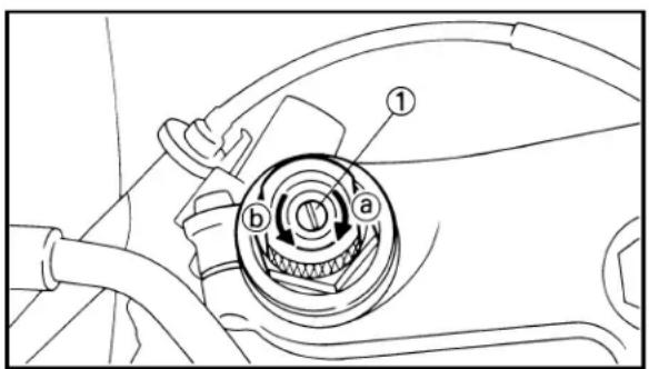
text_image
Technical diagram of a car intake valve with labeled parts and directional arrowsEC36H010
FRONT FORK REBOUND DAMPING FORCE ADJUSTMENT
- Adjust:
- Rebound damping force By turning the adjuster ①.
| Stiffer a → Increase the rebound damping force. (Turn the adjuster 1 in.) |
| Softer b → Decrease the rebound damping force. (Turn the adjuster 1 out.) |

Extent of adjustment:
| Maximum Minimum | |
| Fully turned-in Fully position position | turned-out |
• STANDARD POSITION:
This is the position which is back by the specific number of clicks from the fully turned-in position.

Standard position: 12 clicks out
NOTE:
Fully turn in the adjuster and then turn it out. Specify the position in which the first click is heard as the zero position. If a click is heard just when the adjuster is fully turned in, this position is zero.
CAUTION:
Do not force the adjuster past the minimum or maximum extent of adjustment. The adjuster may be damaged.
WARNING
Always adjust each front fork to the same setting. Uneven adjustment can cause poor handling and loss of stability.

text_image
Technical diagram of a mechanical assembly with labeled parts and directional arrows indicating motion or movement.EC36J030
FRONT FORK COMPRESSION DAMPING FORCE ADJUSTMENT
- Adjust:
- Compression damping force By turning the adjuster ①.
| Stiffer a → Increase the compression damping force. (Turn the adjuster 1 in.) |
| Softer b → Decrease the compression damping force. (Turn the adjuster 1 out.) |
| Extent of adjustment: | ||
| Maximum Minimum | ||
| Fully turned-in position | Fully turned-out position | |
REAR SHOCK ABSORBER INSPECTION/SEAT HEIGHT ADJUSTMENT
INSP ADJ

• STANDARD POSITION:
This is the position which is back by the specific number of clicks from the fully turned-in position.

Standard position: 12 clicks out
NOTE:
Fully turn in the adjuster and then turn it out. Specify the position in which the first click is heard as the zero position. If a click is heard just when the adjuster is fully turned in, this position is zero.
CAUTION:
Do not force the adjuster past the minimum or maximum extent of adjustment. The adjuster may be damaged.
WARNING
Always adjust each front fork to the same setting. Uneven adjustment can cause poor handling and loss of stability.
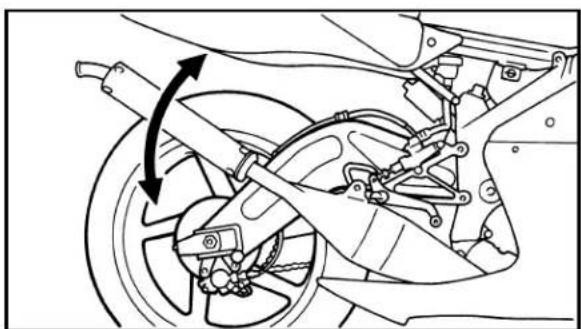
natural_image
Mechanical assembly diagram showing brake system components with no visible text or symbolsEC36K000
REAR SHOCK ABSORBER INSPECTION
- Inspect:
- Swingarm smooth action Abnormal noise/Unsmooth action → Grease the pivoting points or repair the pivoting points.
Damage/Oil leakage → Replace.
EC36L001
SEAT HEIGHT ADJUSTMENT
- Remove:
- Fuel tank
- Adjust:
- Seat height
REAR SHOCK ABSORBER SPRING PRELOAD ADJUSTMENT
INSP ADJ

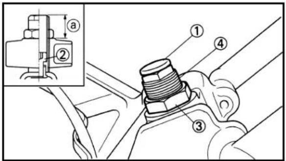
text_image
Technical diagram of a mechanical assembly with numbered parts and an inset showing a component labeled 'a' and section number '②'.| Seat height adjustment steps:Remove the cap 1.Loosen the lock bolt 2 and locknut 3.Turn the adjuster 4 in or out. | |
| Adjuster set length a: | |
| Standard length | Extent of adjustment |
| 27 mm (1.06 in) | 21~33 mm(0.83~1.30 in) |
| NOTE:If the adjuster set length a is changed, the seat height will be increased or decreased by twice the change.CAUTION:Never attempt to turn the adjuster beyond the maximum or minimum length.Tighten the lock bolt and locknut. | |
 | Lock bolt:40 Nm (4.0 m·kg, 29 ft·lb)Locknut:38 Nm (3.8 m·kg, 27 ft·lb) |
| • Install the cap. | |
- Install:
- Fuel tank
EC36M051
REAR SHOCK ABSORBER SPRING PRE-LOAD ADJUSTMENT
-
Hold the machine on upright position by placing the suitable stand.
-
Loosen:
- Locknut ①
NOTE:
When loosening the locknut, use the special tool ② which is included in the owner's tool kit.
- Adjust:
- Spring preload By turning the adjuster ③.
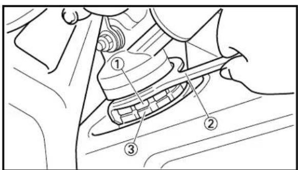
text_image
Technical diagram of a mechanical assembly with numbered components labeled 1, 2, and 3.| Stiffer → | Increase the spring preload.(Turn the adjuster 3 in.) |
| Softer → | Decrease the spring preload.(Turn the adjuster 3 out.) |
REAR SHOCK ABSORBER REBOUND DAMPING FORCE ADJUSTMENT

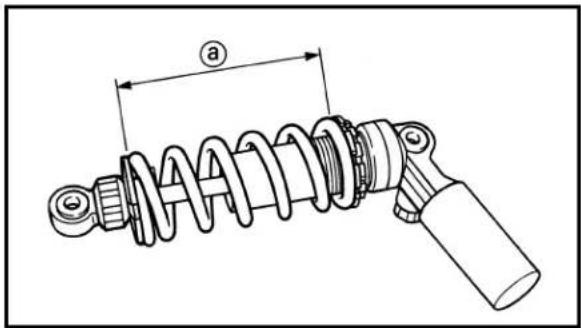
text_image
a| Spring length (installed) a: | ||
| Standard length | Extent of adjustment | |
| 137 mm (5.39 in) | 133~142 mm(5.24~5.59 in) | |
NOTE:
The length of the spring (installed) changes 1.5 mm (0.06 in) per turn of the adjuster.
CAUTION:
Never attempt to turn the adjuster beyond the maximum or minimum setting.
4. Tighten:
- Locknut
20 Nm (2.0 m·kg, 14 ft·lb)

text_image
Technical diagram showing a mechanical component with labeled parts (a, b) and directional arrows indicating motion or movement.EC36N040
REAR SHOCK ABSORBER REBOUND DAMPING FORCE ADJUSTMENT
1. Adjust:
- Rebound damping force By turning the adjuster ①.
| Stiffer a → Increase the rebound damping force. (Turn the adjuster 1 in.) |
| Softer b → Decrease the rebound damping force. (Turn the adjuster 1 out.) |
| Extent of adjustment: | ||
| Maximum Minimum | umum | |
| Fully turned-in Fully position position | turned-out | |
• STANDARD POSITION:
This is the position which is back by the specific number of clicks from the fully turned-in position.
| Standard position:20 clicks out |
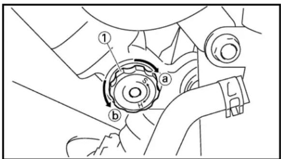
text_image
Technical diagram showing mechanical assembly with labeled parts and directional arrows indicating motion or movement.NOTE:
Fully turn in the adjuster and then turn it out. Specify the position in which the first click is heard as the zero position. If a click is heard just when the adjuster is fully turned in, this position is zero.
CAUTION:
Do not force the adjuster past the minimum or maximum extent of adjustment. The adjuster may be damaged.
EC36P040
REAR SHOCK ABSORBER COMPRESSION DAMPING FORCE ADJUSTMENT
1. Adjust:
- Compression damping force By turning the adjuster ①.
| Stiffer a → Increase the compression damping force. (Turn the adjuster 1 in.) |
| Softer b → Decrease the compression damping force. (Turn the adjuster 1 out.) |
| Extent of adjustment: | ||
| Maximum | Minimum | |
| Fully turned-in position | Fully turned-out position | |
• STANDARD POSITION:
This is the position which is back by the specific number of clicks from the fully turned-in position.
| Standard position:12 clicks out |
NOTE:
Fully turn in the adjuster and then turn it out. Specify the position in which the first click is heard as the zero position. If a click is heard just when the adjuster is fully turned in, this position is zero.
CAUTION:
Do not force the adjuster past the minimum or maximum extent of adjustment. The adjuster may be damaged.
TIRE PRESSURE CHECK/TIRE INSPECTION/WHEEL INSPECTION


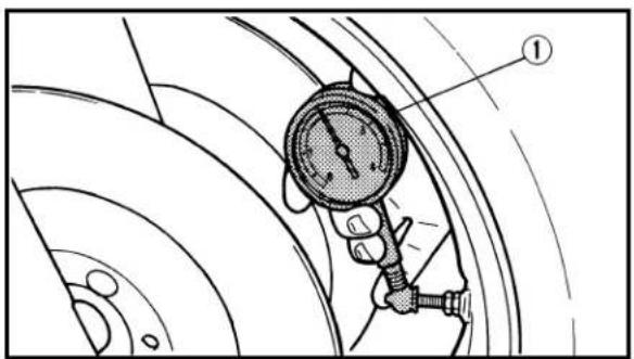
text_image
Technical diagram showing a mechanical pressure gauge with labeled component 1EC36Q011
TIRE PRESSURE CHECK
- Measure:
- Tire pressure
Out of specification → Adjust.
 | Standard tire pressure: | |
| Front Rear | ||
| 200 kPa 200 kPa(2.0 kg/cm2, 29 psi) (2.0 kg/cm2, 29 psi) | ||
NOTE:
Check the tire while it is cold.
①Air gauge
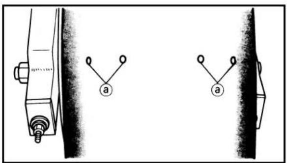
text_image
Diagram showing two mechanical components with labeled terminals and connection points, likely illustrating a mechanical or electrical system.EC36R000
TIRE INSPECTION
- Inspect:
- Tire surfaces
Wear/Damage → Replace.

Minimum tire tread depth ⓐ: 2 mm (0.08 in)
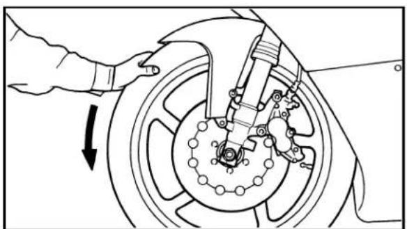
natural_image
Mechanical diagram showing a hand adjusting a car wheel with brake and suspension components (no text or symbols)EC36T000
WHEEL INSPECTION
- Inspect:
- Wheel runout
Elevate the wheel and turn it.
Abnormal runout → Replace.

natural_image
Mechanical assembly diagram showing a hand operating a car tire with rotating components (no text or symbols)- Inspect:
- Bearing free play
Exist play → Replace.
EC36U060 STEERING HEAD INSPECTION AND ADJUSTMENT
- Remove the steering damper at front fork side.
- Elevate the front wheel by placing a suitable stand.

natural_image
Mechanical diagram showing hands operating a brake system with bidirectional arrows indicating motion (no text or symbols)
natural_image
Technical diagram of a mechanical assembly with directional arrows indicating movement or force (no text or symbols present)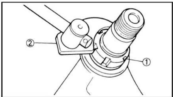
text_image
Technical diagram of a mechanical assembly with labeled parts ① and ②3. Check:
- Steering stem Grasp the bottom of the forks and gently rock the fork assembly back and forth. Free play → Adjust steering head.
4. Check:
- Steering smooth action Turn the handlebar lock to lock. Unsmooth action → Adjust steering ring nut.
5. Adjust:
- Steering ring nut
| Steering ring nut adjustment steps:Remove the cowling.Remove the reservoir tank and handle crown.Loosen the ring nut 1 using ring n wrench 2. | |
 | Ring nut wrench:YU-33975/90890-01403 |

text_image
Technical diagram of a mechanical assembly with numbered components labeled ③, ④, and connection points.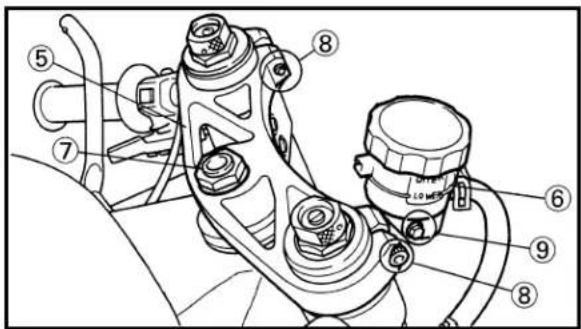
text_image
Technical diagram of a mechanical assembly with numbered components and labeled parts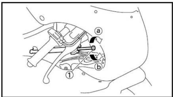
text_image
Technical diagram of a mechanical assembly with labeled parts (a, b, 1) and numbered annotations| • Tighten the ring nut 3 using ring nut wrench 4. NOTE: Set the torque wrench to the ring nut wrench so that they form a right angle. | |
| Ring nut wrench: YU-33975/90890-01403 | |
| Ring nut (initial tightening): 46 Nm (4.6 m·kg, 33 ft·lb) | |
| • Loosen the ring nut one turn. • Retighten the ring nut using the ring nut wrench. AWARNING Avoid over-tightening. | |
| Ring nut (final tightening): 1 Nm (0.1 m·kg, 0.7 ft·lb) | |
| • Check the steering shaft by turning it lock to lock. If there is any binding, remove the steering shaft assembly and inspect the steering bearings. • Install the handle crown 5 and reservoir tank 6. | |
| Steering shaft nut 7: 80 Nm (8.0 m·kg, 58 ft·lb) Pinch bolt (front fork) 8: 20 Nm (2.0 m·kg, 14 ft·lb) Bolt (reservoir tank) 9: 5 Nm (0.5 m·kg, 3.6 ft·lb) | |
| • Install the cowling. | |
6. Install:
- Steering damper
EC36V002
STEERING DAMPER ADJUSTMENT
1. Adjust:
- Damping force
By turning the adjuster ①.
| Stiffer a → Increase the compression damping force. (Turn the adjuster 1 in.) |
| Softer b → Decrease the compression damping force. (Turn the adjuster 1 out.) |
WIRES, CABLES/ COWLING INSTALLATION INSPECTION


Extent of adjustment:
Maximum Minimum
Fully turned-in Fully turned-out position position
• STANDARD POSITION:
This is the position which is back by the specific number of clicks from the fully turned-out position.

Standard position: 0 click in
NOTE:
Fully turn out the adjuster and then turn it in. Specify the position in which the first click is heard as the zero position. If a click is heard just when the adjuster is fully turned out, this position is zero.
CAUTION:
Do not force the adjuster past the minimum or maximum extent of adjustment. The adjuster may be damaged.

natural_image
Technical diagram of a mechanical assembly with directional arrows indicating movement or force (no text or labels present)
natural_image
Technical line drawing of a motorcycle showing internal components and suspension (no text or labels)EC36X001
WIRES, CABLES
- Inspect:
- Smooth movement for steering handle By turning the handlebar lock to lock. If any caught/rubbed → Repair/Replace.
EC36Z001
COWLING INSTALLATION INSPECTION
- Inspect:
- Cowling Loose → Tighten. Stroke the front fork to make sure no parts are being contacted with others. Contact → Repair or replace. - Screen Scratches/fogging → Clean or replace.
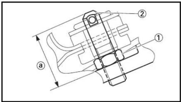
text_image
Technical diagram of a mechanical assembly with labeled parts and dimension annotationsEC36e000 FUEL TANK INSTALLATION INSPECTION
- Inspect:
- Looseness in the installed fuel tank Loose → Adjust.
- Loose the nut ① and screw in the bolt ② a half turn. Then fasten the bolt with the nut. Repeat this until tight.
CAUTION:
Take care so that the bolt protruding length ① is not 29 mm (1.14 in) or over.
LUBRICATION
INSP ADJ

EC36a023
LUBRICATION
To ensure smooth operation of all components lubricate your machine during setup, after break-in, and after every race.
① All control cable
② Brake and clutch lever pivots
③ Throttle-to-handlebar contact
④ Drive chain
⑤ Throttle cable end
⑥ Clutch cable end
A Use Yamaha cable lube or equivalent on these areas.
B Use SAE 10W30 motor oil or suitable chain lubricants.
C Lubricate the following areas with high quality, lightweight lithium-soap base grease.
CAUTION:
Wipe off any excess grease, and avoid getting grease on the brake discs.

text_image
A A A ① ② ③ B C C ④ ⑤ ⑥
text_image
Technical diagram of a mechanical component with labeled parts and directional arrow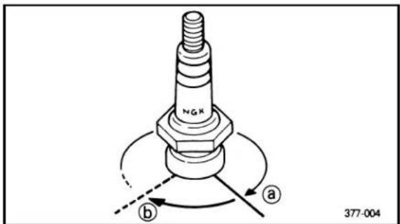
text_image
NGK a b 377-004EC370000
ELECTRICAL
EC371001
SPARK PLUG INSPECTION
- Remove:
- Spark plug
- Inspect:
- Electrode ①
Wear/Damage → Replace.
- Insulator color ②
Normal condition is a medium to light tan color.
Distinctly different color → Check the engine condition.
NOTE:
When the engine runs for many hours at low speeds, the spark plug insulator will become sooty, even if the engine and carburetor are in good operating condition.
- Measure:
- Plug gap ⓐ
Use a wire gauge or thickness gauge.
Out of specification → Regap.

Spark plug gap: 0.5\~0.6 mm (0.020\~0.024 in)
Standard spark plug: R6179A-105P
-
Clean the plug with a spark plug cleaner if necessary.
-
Tighten:
- Spark plug
19 Nm (1.9 m·kg, 13 ft·lb)
NOTE:
- Before installing a spark plug, clean the gasket surface and plug surface.
- Finger-tighten ⓐ the spark plug before torquing to specification ⓑ.

text_image
90° ① ② a bEC372071
IGNITION TIMING CHECK
NOTE:
- The right pick-up coil ① is provided so that ignition timing can be set for both cylinders by adjusting for the left cylinder only. Therefore, do not loosen the screws (right pick-up coil) ②. - When the portion a of the right pick-up coil aligns with the punch mark b on the stator, the right pick-up coil forms an angle of 90^ with the left pick-up coil, indicating that the ignition timing is the same for both cylinders.
-
Remove:
-
Cowling
- Fuel tank
- Spark plugs (left and right cylinder)
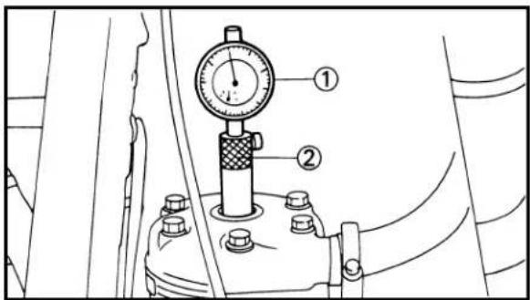
text_image
Technical diagram showing a dial indicator gauge mounted on a mechanical component with numbered parts labeled ① and ②.-
Attach:
-
Dial gauge ①
- Dial gauge stand ②
To left cylinder head.

Dial gauge:
YU-3097/90890-01252
Stand:
YU-1256

text_image
Technical diagram of a mechanical gear assembly with labeled components and an inset gauge showing directional arrows.- Rotate the magneto rotor ① until the piston reaches top dead center (TDC). When this happens, the needle on the dial gauge will stop and reverse directions even though the rotor is being turned in the same direction.
-
Set the dial gauge to zero at TDC.
-
From TDC, rotate the rotor clockwise until the dial gauge indicates that the piston is at a specified distance from TDC.

Ignition timing:
2.4 mm (0.094 in)
BATTERY INSPECTION
INSP ADJ


text_image
Technical diagram of a mechanical assembly with labeled parts a and b, showing components like gears and housing.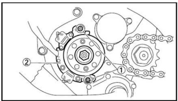
text_image
Technical diagram of a mechanical gear assembly with labeled components 1 and 26. Check:
- Ignition timing
Punch mark ⓐ on rotor should be aligned with punch mark ⓑ on stator.
Not aligned → Adjust.
NOTE:
Be sure to use the punch mark "F1".
7. Adjust:
- Ignition timing
Adjustment steps:
- Loosen the screws (stator) ①.
- Align the punch marks by turning the sta- tor ②.
- Tighten the screws (stator).

Screw (stator): 7 Nm (0.7 m·kg, 5.8 ft·lb)
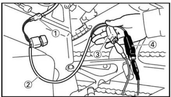
text_image
Technical diagram showing a hand holding a cable with numbered components, likely illustrating a mechanical or automotive assembly.EC375000
BATTERY INSPECTION
WARNING
To prevent danger, read the battery label carefully before handling the battery.
-
Connect the checking lead (supplying parts) ② to the power supply coupler ①.
-
Check:
- Battery voltage
Out of specification → Replace.
| Tester (+) lead → | Red lead 3 |
| Tester (-) lead → | Black lead 4 |
| Battery voltage | Tester selector position | |
| 12.5V or more DCV-20 | ||
EC376000
RECHARGING BATTERY
WARNING
- Keep the battery away from fire.
- When charging the battery, be sure to remove it from the chassis and use the checking lead (supplying parts).
- Be sure to use the specific charging current and voltage when charging the battery.
- Do not quick charge the battery.
- For battery replacement, be sure to use a sealed type specified for the TZ250.
NOTE:
Battery can be recharged using either an MF battery devoted charger or automobile battery.
[Using the MF battery devoted charger]
-
Remove:
-
Seat
-
Battery
-
Connect the battery charger ① for MF batteries to the battery ② using the checking lead (supplying parts) ③, and recharge the battery.
| Battery charger (+) lead → | Red lead 4 |
| Battery charger (-) lead → | Black lead 5 |
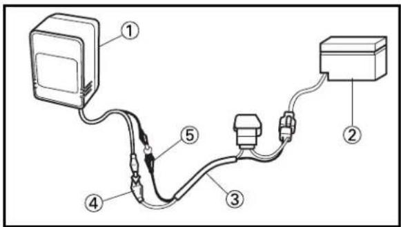
text_image
Diagram of a cable or connector assembly with labeled parts 1 through 5, showing connections between components.| Battery charger for MF batteries:GS TYPE BC-601-12V | |
| Charging time:5 hours | |
| Voltage when charged:12.8V or more |
CAUTION:
Make sure that the red and black leads do not contact each other during recharge.

text_image
Diagram of an electrical circuit with labeled components including a battery, plug, and terminal block[Using the automobile battery]
-
Remove:
-
Seat
-
Battery
-
Connect an automobile battery ① to the battery ② using the checking lead (supplying parts) ③, and recharge the battery.
Automobile battery (+) lead → Red lead ④
Automobile battery (-) lead → Black lead ⑤

Charge time: 3 hours

Voltage when charged: 12.8V or more (or 12.5V or more) Voltage of the automobile battery for power supply: 12.8\~13.8V (maximum 14.9V)
NOTE:
If the battery is recharging using an automobile battery, the charge may not exceed 12.8V. Then, 12.5V or more will be OK.
CAUTION:
- For an automobile battery for supply, use a battery with a capacity of 12V20Ah or more with a voltage 12.8 to 13.2.
- During the battery recharge, do not recharge the power supply battery by starting or running the engine.
- Connect only one battery for recharge.
EC400000
ENGINE
EC4V0000
COWLING, INDUCTION GUIDE, SEAT AND FUEL TANK

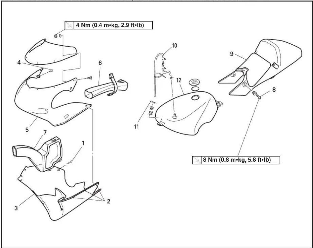
text_image
4 Nm (0.4 m•kg, 2.9 ft•lb) 8 Nm (0.8 m•kg, 5.8 ft•lb)Extend of removal: ① Cowling removal ② Induction guide removal
③ Seat removal ④ Fuel tank removal
| Extend of removal Order Part name Q'ty Remarks | ||||
| Preparation for Turn the fuel cock to “OFF”.removal Disconnect the fuel hose. | ||||
 | 1 Clip (lower cowl) 12 Quick fastener 53 Lower cowl 14 Clip (upper cowl) 35 Upper cowl 16 Induction guide (left cylinder) 17 Induction guide (right cylinder) 18 Screw (seat) 49 Seat 110 Fuel tank breather hose11 Clip (fuel tank)12 Fuel tank 1 | |||
| 1 Refer to “REMOVAL POINTS”.1 | ||||
COWLING, INDUCTION GUIDE, SEAT AND FUEL TANK
ENG

text_image
Technical diagram showing a mechanical assembly with labeled parts and an inset view of a device connection.EC4V3000
REMOVAL POINTS
EC4U3100
Fuel tank breather hose
- Disconnect:
- Fuel tank breather hose ①
NOTE:
Disconnect the fuel tank breather hose with the valve joint ② remaining on the fuel tank side so as to prevent fuel from spurting out by the tank inner pressure.
EC4S0000
EXHAUST PIPE AND SILENCER


text_image
11 Nm (1.1 m·kg, 8.0 ft·lb) 21 Nm (2.1 m·kg, 15 ft·lb) New New 1 2 3 4 5 11 Nm (1.1 m·kg, 8.0 ft·lb) 21 Nm (2.1 m·kg, 15 ft·lb)Extend of removal: ① Exhaust pipe removal ② Silencer removal
| Extend of removal Order Part name Q'ty Remarks | ||||
| Preparation for Lower cowl Refer to “COWLING, INDUCTIONremoval GUIDE, SEAT AND FUEL TANK” | section. | |||
| 1 Tension spring 2ea.2 Bolt (exhaust pipe) 1ea.3 Exhaust pipe 1ea.4 Bolt (silencer) 2ea.5 Silencer 1ea. | ||||
EC450001
RADIATOR

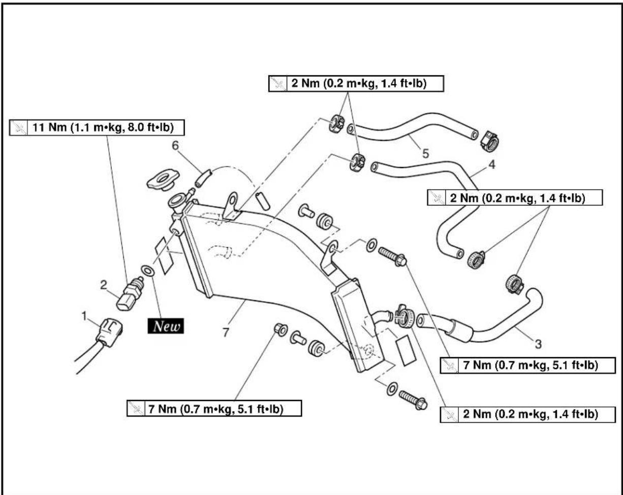
text_image
11 Nm (1.1 m•kg, 8.0 ft•lb) New 2 Nm (0.2 m•kg, 1.4 ft•lb) 2 Nm (0.2 m•kg, 1.4 ft•lb) 7 Nm (0.7 m•kg, 5.1 ft•lb) 7 Nm (0.7 m•kg, 5.1 ft•lb) 2 Nm (0.2 m•kg, 1.4 ft•lb)Extend of removal: ① Radiator removal
| Extend of removal Order Part name Q'ty Remarks | ||||
| Preparation for Cowling, induction guide Refer to “COWLING, INDECTIONremoval and fuel tank GUIDE, SEAT AND FUEL TANK”Drain the cooling water. Refer to “COOLANT REPLACEMENT”section in the CHAPTER 3. | ||||
| 1 Water temperature gauge lead 12 Thermo unit 13 Radiator hose 2 14 Radiator hose 4 15 Radiator hose 3 16 Radiator breather hose 17 Radiator 1 | ||||
EC456000
HANDLING NOTE
WARNING
Do not remove the radiator cap when the engine and radiator are hot. Scalding hot fluid and steam may be blown out under pressure, which could cause serious injury.
When the engine has cooled, open the radiator cap by the following procedure: Place a thick rag, like a towel, over the radiator cap, slowly rotate the cap counterclockwise to the detent. This procedure allows any residual pressure to escape. When the hissing sound has stopped, press down on the cap while turning counterclockwise and remove it.

natural_image
Technical line drawing of a heat exchanger or radiator with labeled component (1), showing internal structure and mounting points (no text or symbols beyond label)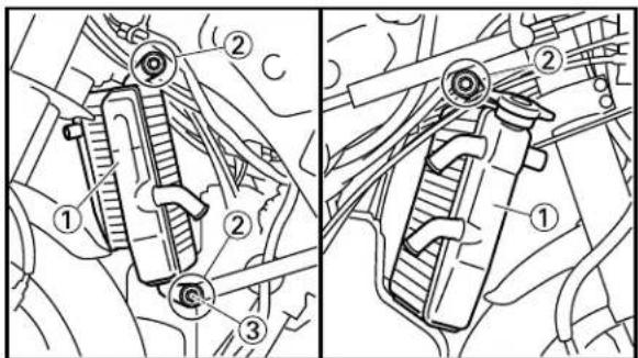
text_image
Technical diagram showing mechanical assembly with numbered components and directional arrows indicating motion or flow.EC454000
INSPECTION
EC444100
Radiator
- Inspect:
- Radiator core ① Obstruction → Blow out with compressed air through rear of the radiator. Bent fin → Repair/replace.
EC455000
ASSEMBLY AND INSTALLATION
EC455141
Radiator
-
Install:
-
Radiator ①
- Bolt (radiator) ②
- Nut (radiator) ③
7 Nm (0.7 m·kg, 5.1 ft·lb)
7 Nm (0.7 m·kg, 5.1 ft·lb)
RADIATOR
ENG


text_image
Technical diagram of a mechanical assembly with numbered components and a labeled 'New' section showing a connector.
text_image
Technical diagram of a mechanical assembly with labeled parts, likely for automotive or industrial maintenance.2. Install:
- Radiator breather hose ①
- Radiator hose 3 ②
2 Nm (0.2 m·kg, 1.4 ft·lb)
- Radiator hose 4 ③
4 ③
2 Nm (0.2 m·kg, 1.4 ft·lb)
2 Nm (0.2 m·kg, 1.4 ft·lb)
- Radiator hose 2 ④
2④
2 Nm (0.2 m·kg, 1.4 ft·lb)
2 Nm (0.2 m·kg, 1.4 ft·lb)
- Gasket ⑤ New
• Thermo unit ⑥ 11 Nm (1.1 m·kg, 8.0 ft·lb)
• Water temperature gauge lead ⑦
NOTE:
Insert the end of the radiator breather hose into the frame. Refer to "CONTROL FUNCTION" section in the CHAPTER 1.
EC460000
CARBURETOR AND REED VALVE


text_image
2 Nm (0.2 m·kg, 1.4 ft·lb) 6 7 2 Nm (0.2 m·kg, 1.4 ft·lb) New 11 Nm (1.1 m·kg, 8.0 ft·lb) 1 Nm (0.1 m·kg, 0.7 ft·lb) New 11 Nm (1.1 m·kg, 8.0 ft·lb) 1 Nm (0.1 m·kg, 0.7 ft·lb)| Extend of removal Order Part | name Q'ty Remarks | |||
| Preparation for Cowling, induction removal and fuel tank GUIDE, GUIDE, | CARBURETOR AND REED VALVE REMOVALion guide Refer to “COWLING, INDUCTION SEAT AND FUEL TANK”Spark plug cap (left cylinder)Radiator hose 3 Refer to “RADIATOR”Bolt (radiator stay) Shift the radiator Servicing the forward.Tension spring [exhaust pipe (left cylinder)] | section.section.+forward. | ||

text_image
2 Nm (0.2 m·kg, 1.4 ft·lb) 2 Nm (0.2 m·kg, 1.4 ft·lb) 11 Nm (1.1 m·kg, 8.0 ft·lb) 1 Nm (0.1 m·kg, 0.7 ft·lb) New 11 Nm (1.1 m·kg, 8.0 ft·lb) 1 Nm (0.1 m·kg, 0.7 ft·lb)Extend of removal: ① Carburetor removal ② Reed valve removal
| Extend of removal Order Part name Q'ty Remarks | ||||
 | 1 Induction cap (left cylinder) 1 Servicing the left cylinder2 Solenoid valve lead 1ea. Disconnect the solenoid valve lead.3 Clamp (carburetor joint) 1ea. Loosen the screw (carburetor joint).4 Carburetor 1ea.5 Fuel hose 1ea.6 Grommet 2 Pull up by slit end. Servicing the 7 Induction cap (right cylinder) 18 Induction box 1ea.9 Carburetor joint 1ea.10 Reed valve assembly 1ea.11 Stopper (reed valve) 2ea.12 Reed valve 2 2ea.13 Reed valve 1 2ea. | |||
EC468000
CARBURETOR DISASSEMBLY

text_image
2 Nm (0.2 m·kg, 1.4 ft·lb)Extend of removal: ① Carburetor disassembly
| Extend of removal Order Part name Q'ty Remarks | |||
| CARBURETOR DISASSEMBLY | |||
| 1 | 1 Mixing chamber top 12 Throttle valve 1 Refer to “REMOVAL POINTS”.3 Needle holder 14 Jet needle 15 $starter plunger6 Float chamber7 Power jet8 Float pin9 Float10 Valve seat 111 Main jet12 Main nozzle13 Pilot jet14 Pilot air screw 115 Solenoid valve | 1111111111111111111111111111111111111111111111111111111111111111111111111111111111111111111111111111 | |
CARBURETOR AND REED VALVE
ENG

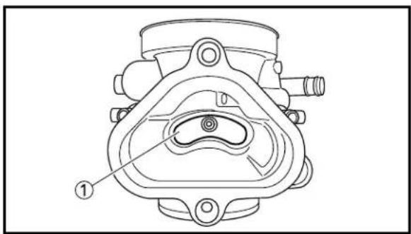
text_image
Technical diagram of a mechanical component with numbered callouts pointing to features
text_image
Technical diagram of a mechanical assembly with numbered components for identificationEC466010
HANDLING NOTE
CAUTION:
Do not disassemble the venturi block ① because it will cause a drop in carburetor performance.
EC463000
REMOVAL POINTS
EC463110
Throttle valve
-
Remove:
-
Throttle valve ①
- Ring ②
- Spring (throttle valve) ③
- Mixing chamber top ④
- Throttle cable ⑤
NOTE:
While compressing the spring (throttle valve), disconnect the throttle cable.
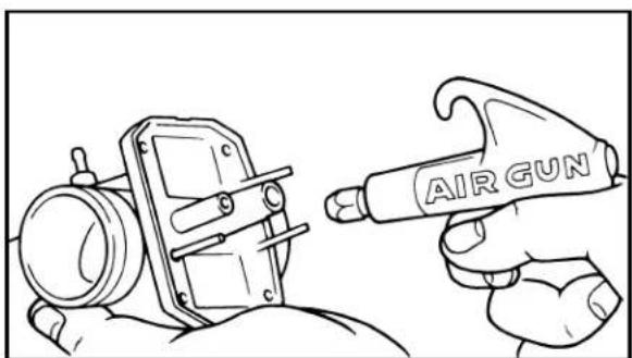
natural_image
Line drawing of a hand using a gun to brush a cylindrical object, no text or symbols present
text_image
Diagram showing four labeled mechanical components with numbered parts, likely illustrating a assembly or assembly process.EC464000
INSPECTION
EC464120
Carburetor
-
Inspect:
-
Carburetor body
Contamination → Clean.
NOTE:
- Use a petroleum based solvent for cleaning. Blow out all passages and jets with compressed air.
-
Never use a wire.
-
Inspect:
-
Main jet ①
- Main nozzle ②
- Pilot jet ③
- Power jet ④
Contamination → Clean.
NOTE:
- Use a petroleum based solvent for cleaning. Blow out all passages and jets with compressed air.
- Never use a wire.
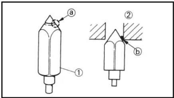
text_image
Technical diagram showing two mechanical components labeled ① and ② with annotations a and b, likely illustrating a cutting or machining process.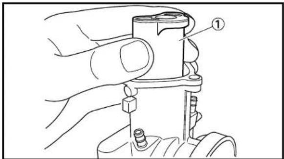
text_image
Technical diagram showing a hand holding a mechanical component with labeled parts ①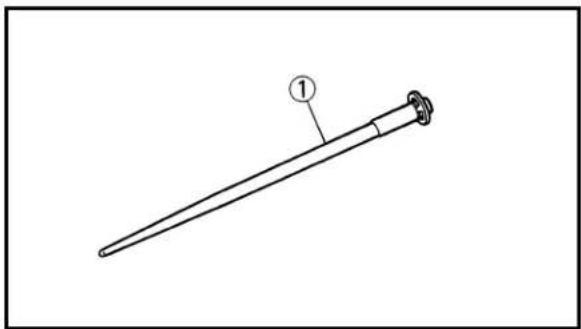
natural_image
Line drawing of a mechanical tool or rod with a labeled end (1), no text or symbols present.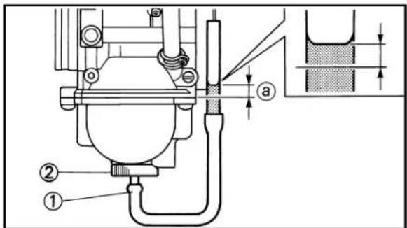
text_image
Technical diagram of a mechanical device with labeled components and an inset showing a cross-sectional view.EC464200
Needle valve
-
Inspect:
-
Needle valve ①
- Valve seat ②
Grooved wear ⓐ → Replace.
Dust ⓑ → Clean.
NOTE:
Always replace the needle valve and valve seat as a set.
EC464301
Throttle valve
- Check:
- Free movement
Stick → Repair or replace.
NOTE:
Insert the throttle valve ① into the carburetor body, and check for free movement.
EC464420
Jet needle
- Inspect:
- Jet needle ①
Bends/Wear → Replace.
- Clip groove
Free play exists/Wear → Replace.
EC464802
FUEL LEVEL
- Measure:
- Fuel level ⓐ
Out of specification → Adjust.

Fuel level:
6.0\~7.0 mm (0.24\~0.28 in)
Above the float chamber mat- ing surface
| Measurement and adjustment steps:Remove the drain plug.Connect the fuel level gauge adapter 2and fuel level gauge 1 to the float chamber. | |
 | Fuel level gauge adapter:YM-1470/90890-01470Fuel level gauge:YM-1312-A/90890-01312 |
Fuel level gauge adapter:

natural_image
Technical line drawing of a mechanical clamp or bracket assembly (no text or symbols)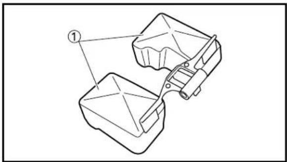
natural_image
Technical line drawing of a mechanical component with two parts, one labeled with number 1 (no text or symbols present)
natural_image
Simple line drawing of a mechanical linkage or support structure with labeled point 'a' (no text or symbols beyond basic geometry)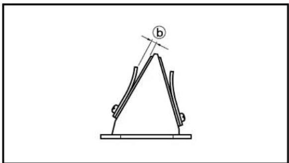
natural_image
Simple line drawing of a mechanical linkage or support structure with no text or symbols- Hold the fuel level gauge vertically next to the float chamber mating surface.
- Measure the fuel level with the fuel level gauge.
NOTE:
Keep the carburetor and fuel level gauge vertically when measuring the fuel level.
- If the fuel level is not within specification, inspect the valve seat and needle valve.
- If either is worn, replace them both.
- If both are fine, adjust the fuel level by bending the float tab ⑥ on the float.
- Recheck the fuel level.
EC464600
Float
- Inspect:
- Float ①
Damage → Replace.
EC464701
Reed valve
- Measure:
- Reed valve bending ⓐ
Out of specification → Replace.

Reed valve bending limit: 0.2 mm (0.008 in)
- Valve stopper height ⑥
Out of specification → Adjust stopper/Replace valve stopper.

Valve stopper height: 6.5\~6.9 mm (0.256\~0.272 in)
CARBURETOR AND REED VALVE
ENG

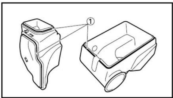
natural_image
Technical line drawing of a two-part mechanical device with labeled parts (no text or symbols present)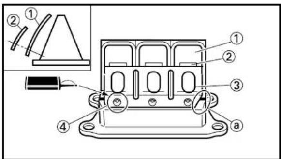
text_image
Technical diagram of an electronic component with numbered parts and a close-up inset showing a pin insertion mechanism.EC464900
Induction box
- Inspect:
- Seal ①
Peeled → Stick using the instantaneous adhesive
Crack/Wear/Damage → Replace.
EC465000
ASSEMBLY AND INSTALLATION
EC465180
Reed valve
-
Install:
-
Reed valve 1 ①
- Reed valve 2 ②
- Stopper (reed valve) ③
- Screw (reed valve) ④

1 Nm (0.1 m·kg, 0.7 ft·lb)
NOTE:
• Install the reed valve with the reed valve bending as shown.
- Note the cut ⓐ in the lower corner of the reed and stopper plate.
CAUTION:
Tighten each screw gradually to avoid warping.

text_image
① New ② a- Install:
• Gasket (reed valve assembly) ① New
- Reed valve assembly ②
NOTE:
Install the gasket (left cylinder) with its projection @ facing upward and the seal print side toward the crankcase.
CARBURETOR AND REED VALVE
ENG


text_image
Technical diagram of a mechanical component with numbered parts, likely for assembly or maintenance instructions.
text_image
Technical diagram of a vehicle suspension system with numbered components for identification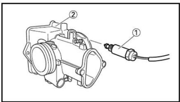
text_image
Technical diagram of a mechanical assembly with labeled parts ① and ②, showing a component connected to a cable.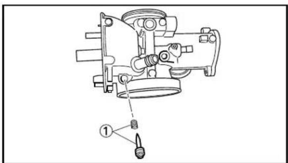
text_image
Technical diagram of a mechanical component with labeled parts and an arrow indicating assembly direction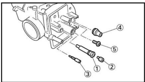
text_image
Technical diagram of a mechanical assembly with numbered parts for identification3. Install:
- Carburetor joint ①
- Induction box ②
- Bolt {carburetor joint [ℓ=25 mm (0.98 in)]} ③
11 Nm (1.1 m·kg, 8.0 ft·lb)
- Bolt {carburetor joint [ℓ=20 mm (0.79 in)]} ④
11 Nm (1.1 m·kg, 8.0 ft·lb)
EC4652E0
Carburetor
1. Install:
- Solenoid valve ①
To carburetor ②.
2. Install:
- Pilot air screw ①
Note the following installation points:
- Screw in the pilot air screw until it is lightly seated.
- Back out it by the specified number of turns.

Pilot air screw:
1-1/2 of turns out
3. Install:
- Main nozzle ①
- Main jet ②
- Pilot jet ③
- Valve seat ④
- Screw (valve seat) ⑤

text_image
Technical diagram of a mechanical component with numbered parts labeled 1 to 4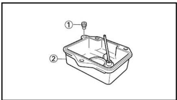
text_image
Technical diagram of a mechanical component with labeled parts ① and ②
text_image
Technical diagram of a battery rear panel with labeled components and parts, including zoomed-in detail view.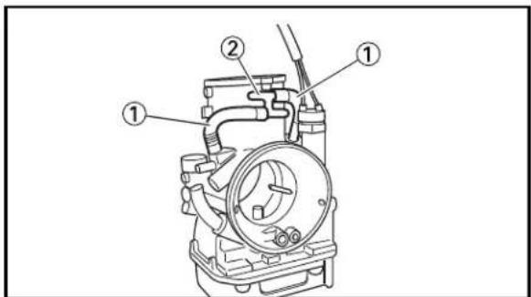
text_image
Technical diagram of a mechanical component with numbered parts labeled ①, ②, and ①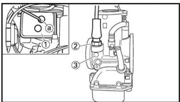
text_image
Technical diagram of a mechanical assembly with numbered parts and an inset detail view labeled 'a'-
Install:
-
Needle valve ①
- Float ②
- Float pin ③
- Screw (float pin) ④
NOTE:
• After installing the needle valve to the float, install them to the carburetor.
- Check the float for smooth movement.
- Install:
- Power jet ①
To float chamber ②.
CAUTION:
Do not tighten the power jet too hard, or you may not remove it when checking and replacing it.
-
Install:
-
Float chamber ①
- Screw (float chamber) ②
CAUTION:
Do not confuse the left and right float chambers in installation because they are different from each other. The overflow hole ^① is in the bottom of the float chamber for the left cylinder and for the right one in the side.
-
Install:
-
Air vent hose ①
-
Joint ②
-
Install:
-
Induction cap ① (right cylinder only)
- Starter plunger ②
To carburetor ③.
NOTE:
Install the stater plunger (right cylinder) after passing it through the hole ⓐ of the induction cap. Refer to "CABLE ROUTING DIAGRAM" section in the CHAPTER 2.
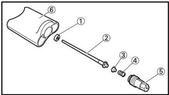
text_image
Exploded view diagram of a mechanical component with numbered parts for identification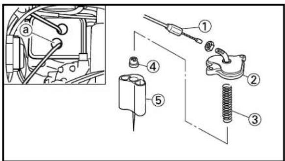
text_image
Technical diagram of a mechanical assembly with numbered parts, including tool, spring, and housing components.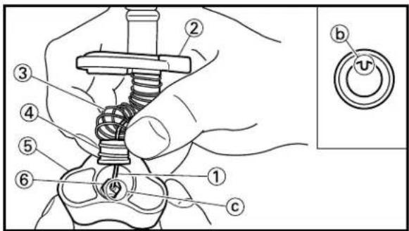
text_image
Technical diagram showing a hand operating a mechanical switch with numbered parts and a close-up of the button labeled 'b' with a circular symbol.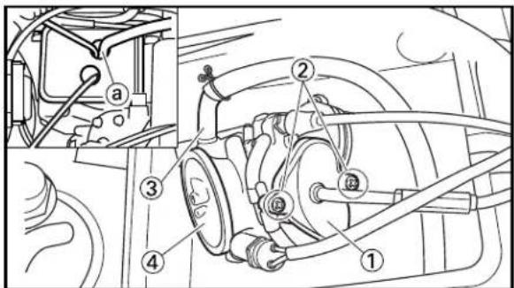
text_image
Technical diagram of a vehicle suspension system with numbered components and an inset view labeled 'a'9. Install:
- Collar ①
- Jet needle ②
- Spring guide ③
- Spring ④
- Needle holder ⑤
To throttle valve ⑥.
10. Install:
- Throttle cable ①
- Mixing chamber top ②
• Spring (throttle valve) ③ - Ring ④
- Throttle valve ⑤
NOTE:
- Install the throttle cable (right cylinder) after passing it through the hole ⓐ of the induction cap. Refer to "CABLE ROUTING DIAGRAM" section in the CHAPTER 2.
- While compressing the spring, connect the throttle cable.
- Align the projection ⑥ on the ring with the groove ⑤ in the needle holder ⑥.
11. Install:
- Mixing chamber top ①
- Screw (mixing chamber top) ②
2 Nm (0.2 m·kg, 1.4 ft·lb)
- Fuel hose ③
To carburetor ④.
NOTE:
- Install the fuel hose (right cylinder) after passing it through the hole ⓐ of the induction cap. Refer to "CABLE ROUTING DIAGRAM" section in the CHAPTER 2.
• After installing, check the throttle grip for smooth movement.
CARBURETOR AND REED VALVE
ENG


natural_image
Technical line drawing of a mechanical assembly with hoses and components (no text or symbols)
natural_image
Technical line drawing of a mechanical assembly with hoses and components (no text or symbols)
text_image
Technical diagram showing engine components with labeled parts (a) and (i), including wiring and valve assembly.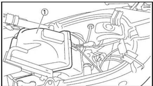
text_image
Technical diagram of a car engine compartment with numbered component and labeled parts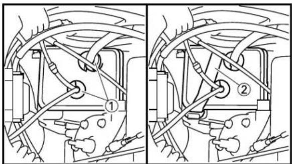
text_image
Technical diagram showing mechanical assembly with labeled parts, including numbered annotations ① and ②EC465370
Carburetor installation
- Install:
- Carburetor ①
NOTE:
Install the projection between the carburetor joint slots.
- Tighten:
- Clamp (carburetor joint) ①
2 Nm (0.2 m·kg, 1.4 ft·lb)
- Connect:
- Solenoid valve lead ①
NOTE:
Install the solenoid valve lead (right cylinder) after passing it through the hole ⓐ of the induction cap. Refer to “CABLE ROUTING DIAGRAM” section in the CHAPTER 2.
- Install:
- Induction cap ① (left cylinder only)
- Install:
• Grommet ① (right cylinder only)
• Band ② (right cylinder only)
EC470000
CYLINDER HEAD, CYLINDER AND PISTON
EC478000
CYLINDER HEAD AND CYLINDER

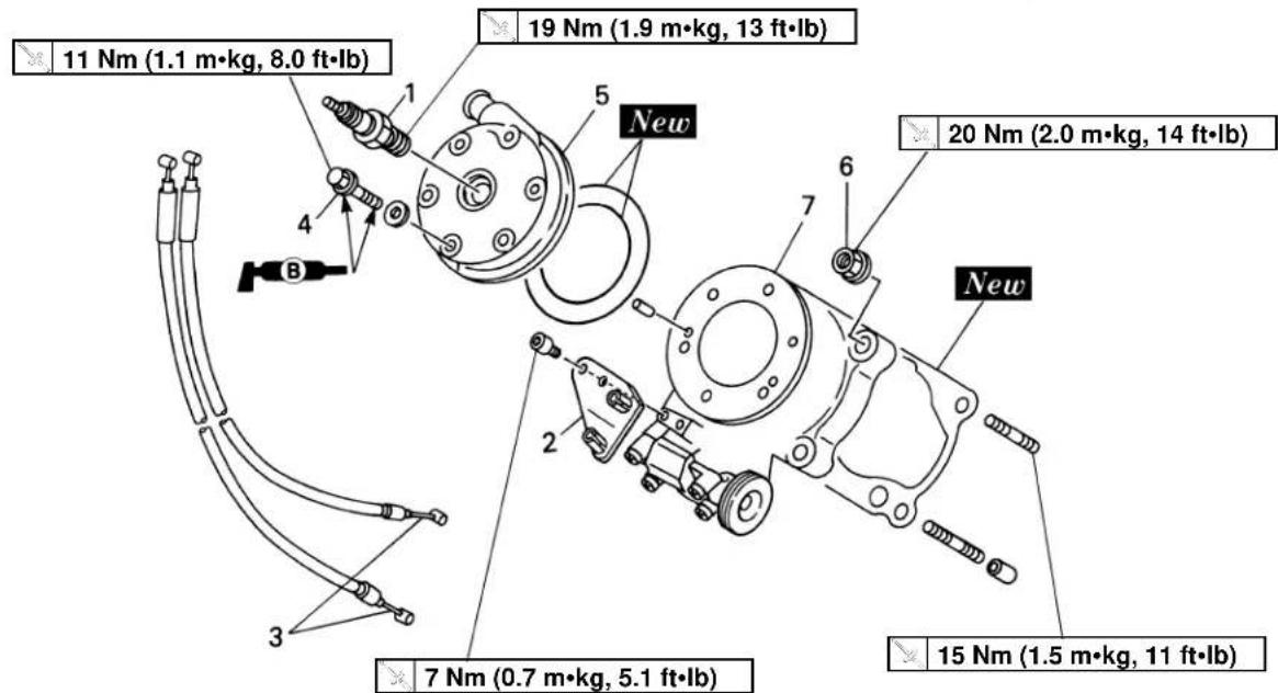
text_image
11 Nm (1.1 m•kg, 8.0 ft•lb) 19 Nm (1.9 m•kg, 13 ft•lb) 20 Nm (2.0 m•kg, 14 ft•lb) 7 Nm (0.7 m•kg, 5.1 ft•lb) 15 Nm (1.5 m•kg, 11 ft•lb)Extend of removal: ① Cylinder head removal ② Cylinder removal
| Extend of removal Order Part | name Q'ty Remarks | |||
| Preparation for Cowling and fuel tank Refer to “COWLING, INDUCTION removal GUIDE, SEAT AND FUEL TANK”Exhaust pipe Refer to “EXHAUST PIPE AND SILENCER” section.Radiator hose 3, 4 Disconnect at cylinder head side.Carburetor (left cylinder)Induction guide (left cylinder) | section.ANDServicing the left cylinder | |||
 | 1 | Spark plug | 1ea. | Refer to “REMOVAL POINTS”. |
| 2 | Cable stay 1ea. | 2ea. | ||
| 3 | YPVS cable | 6ea. | Loosen each bolt 1/4 turn, and remove them after all bolts are loosened. | |
| 4 | Bolt (cylinder head) | 1ea. | ||
| 5 | Cylinder head | 4ea. | ||
| 6 | Nut (cylinder) | 1ea. | ||
| 7 | Cylinder | 1ea. | ||
EC478100
PISTON AND POWER VALVE
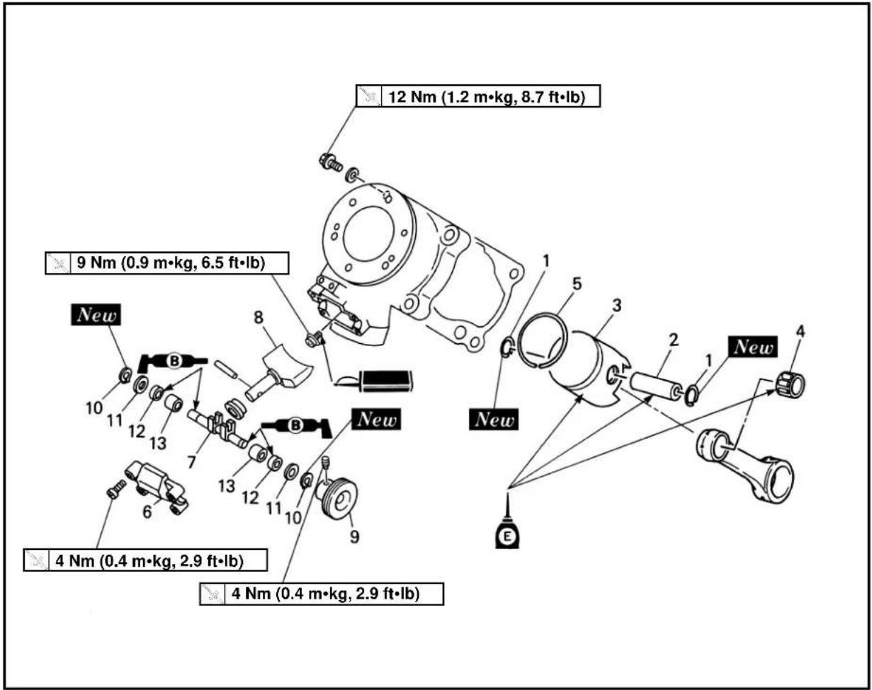
text_image
12 Nm (1.2 m·kg, 8.7 ft·lb) 9 Nm (0.9 m·kg, 6.5 ft·lb) New 4 Nm (0.4 m·kg, 2.9 ft·lb) 4 Nm (0.4 m·kg, 2.9 ft·lb)Extend of removal:
① Piston and piston ring removal
② Power valve removal
| Extend of removal Order Part name Q'ty Remarks | ||||
| (24001) | (7753) | PISTON REMOVAL1 Piston pin clip 2ea.2 Piston pin 1ea.3 Piston 1ea. Refer to "REMOVAL POINTS".4 Small end bearing 1ea.5 Piston ring 1ea.6 Valve cover 1ea.7 Valve shaft 1ea.8 Power valve 1ea.9 Valve pulley 1ea.10 Circlip 2ea.11 Plain washer 2ea.12 Oil seal 2ea.13 Solid bush 2ea. | ||

text_image
Technical diagram showing mechanical assembly with labeled component ①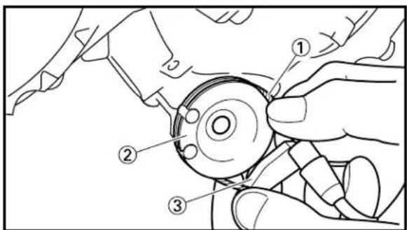
text_image
Technical diagram showing hands operating a mechanical component with numbered parts labeled ①, ②, and ③.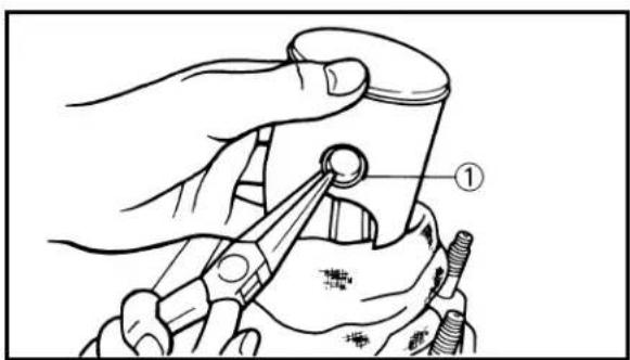
text_image
Technical diagram showing a hand using a tool to adjust a circular component, labeled with number ①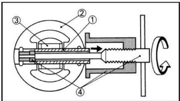
text_image
Technical diagram of a mechanical assembly with numbered components and directional arrows indicating motion or flow.EC473000
REMOVAL POINTS
EC473310
YPVS cable
- Remove:
- Bolt (cable stay) ①
- Remove:
- YPVS cable ①
From the valve pulley ②.
NOTE:
Remove the YPVS cable together with the cable stay ③.
EC473402
Piston and piston ring
- Remove:
- Piston pin clip ①
NOTE:
Before removing the piston pin clip, cover the crankcase with a clean rag to prevent the piston pin clip from falling into the crankcase cavity.
-
Remove:
-
Piston pin ①
- Piston ②
- Small end bearing ③
NOTE:
Before removing the piston pin, deburr the clip groove and pin hole area. If the piston pin groove is deburred and piston pin is still difficult to remove, use the piston pin puller ④.

Piston pin puller: YU-1304/90890-01304
CAUTION:
Do not use a hammer to drive the piston pin out.
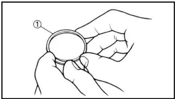
natural_image
Line drawing of a hand holding a circular ring, with no text or symbols present
natural_image
Line drawing of a hand holding a circular mechanical component with concentric rings and mounting holes (no text or symbols)
text_image
Technical diagram of a mechanical component with labeled parts (a, b, c) and an inset showing a cross-sectional view.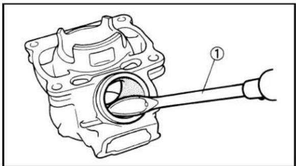
natural_image
Technical line drawing of a mechanical component with a shaft and housing (no text or symbols)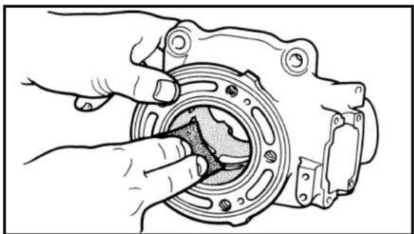
natural_image
Illustration of hands fastening a mechanical component with a circular housing and bolted joints (no text or symbols)- Remove:
- Piston ring ①
NOTE:
Take care not to scratch the piston or damage the piston ring by expanding it more than necessary.
EC474000
INSPECTION
EC474110
Cylinder head
- Remove:
- Carbon deposits Use #400\~600 grit wet sandpaper.
- Inspect:
- Cylinder head water jacket Crust of minerals/Rust → Remove. - Cylinder head contact surface Wear/Damage → Replace. - Recess of insert portion ⓐ The contact surface Ⓑ of the insert portion is recessed below the aluminum portion Ⓒ → Replace.
EC474211
Cylinder
- Remove:
• Carbon deposits Use a rounded scraper ①.
NOTE:
Do not use a sharp instrument. Avoid scratching the aluminum.
- Inspect:
- Cylinder inner surface Score marks → Repair or replace. Using wet sandpaper (#240), repair in the same crisscross patterns as the honed ones.
CAUTION:
- Do not rebore the cylinder. - Minimize modification by wet sandpaper. Do not rub too much.
- Inspect:
- Travel distance for cylinder 3,000 km (1,800 miles) or more → Replace.

text_image
Diagram illustrating a physical process with labeled parts (a) and (b), showing directional arrows and a hand interacting with a surface.
natural_image
Simple line drawing of a mechanical component with two flanges and a central oval shape (no text or symbols)EC474B00
Piston
-
Inspect:
-
Piston crown Damage and crack due to detonation → Replace.
- Piston pin hole Crack → Replace.
- Contact with cylinder Excessive scuffing, score ① → Use #240\~320 grit wet sandpaper in a criss-cross manner ②.
-
Heat discoloration → Replace.
-
Inspect:
- Travel distance for piston 500 km (300 miles) or more → Replace.
EC474A00
Contact surface roughening for piston replacement
NOTE:
- Roughening the cylinder wall for a replaced piston helps toward smoother contact surfaces and prevents trouble that would otherwise occur.
-
If a new piston is installed to a cylinder without honed patterns, the contact surfaces will not fit properly because of eccentric wear caused by sliding motion.
-
Inspect:
- Honed patterns on the cylinder wall Using wet sandpaper (#240), rub the area without honed patterns in the same crisscross patterns as the honed ones (especially, along the periphery of the exhaust port).
CAUTION:
Minimize modification by wet sandpaper. Do not rub too much.
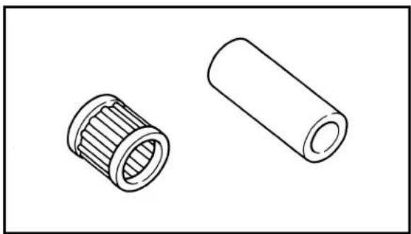
natural_image
Technical line drawing of two mechanical components: a cylindrical roller and a hollow cylinder (no text or symbols)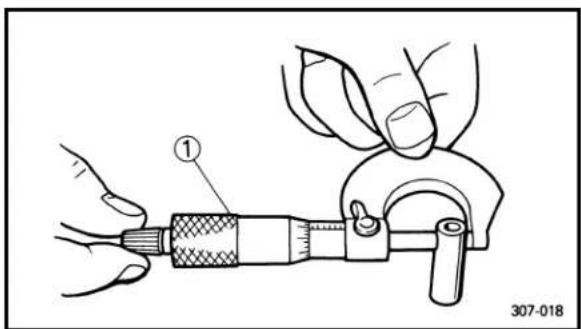
text_image
① 307-018
text_image
Technical diagram showing a hand holding a mechanical component with labeled parts ① and ②EC474402
Piston pin and small end bearing
1. Inspect:
- Piston pin
- Small end bearing
Signs of heat discoloration → Replace.
2. Measure:
- Piston pin outside diameter
Use micrometer ①.
Out of limit → Replace.
| Piston pin outside diameter: | |
| Standard | |
| 14.995~15.000 mm (0.5904~0.5906 in) | 14.975 mm (0.5896 in) |
3. Check:
- Free play (when the piston pin ① is in place in the piston ②)
There should be no noticeable for the play.
Free play exists → Replace piston pin and/or piston.
4. Install:
- Small end bearing
- Piston pin
Into the small end of connecting rod.
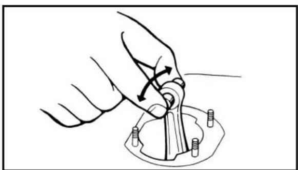
natural_image
Illustration of a hand turning a mechanical component with pins, no text or symbols present5. Check:
- Free play
There should be no noticeable free play.
Free play exists → Inspect the connecting rod for wear/Replace the pin and/or connecting rod as required.
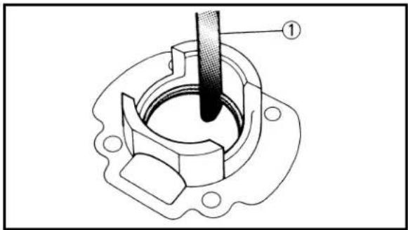
text_image
Technical diagram of a mechanical component with labeled part ①EC474530
Piston ring
1. Install:
- Piston ring
Into the cylinder.
Push the ring with the piston crown.
2. Measure:
- End gap
Use a thickness gauge ①.
Out of limit → Replace.
| Ring end gap (installed): | |
| Standard | |
| 0.22~0.37 mm 0.59 mm(0.009~0.015 in) (0.023 in) | |

natural_image
Illustration of hands using a tool to cut a circular object, labeled with number 1 (no text or symbols on the diagram itself)3. Measure:
- Side clearance
Use a thickness gauge ①.
Out of specification → Replace piston and/or ring.
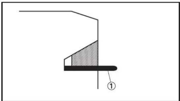
natural_image
Pure mechanical diagram showing a stepped component with hatched area and labeled point (1), no text or symbols present.| Side clearance: | ||
| Standard | ||
| Zero~0.06 mm(Zero~0.0024 in) | - | |

text_image
Technical diagram of a mechanical component with labeled parts A and a, showing internal structure and assembly.NOTE:
- Insert the thickness gauge deep in the piston ring groove. Then measure the clearance with both sliding surfaces being flush with each other.
- Check at several points.
EC474720
Combination of piston and cylinder
1. Check:
- Cylinder mark ⓐ
| Cylinder mark @ |
| A |
| B |
| C |

text_image
A a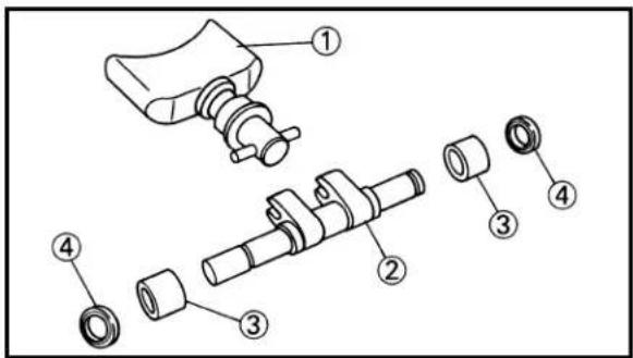
text_image
Exploded view diagram of a mechanical assembly with numbered parts for identification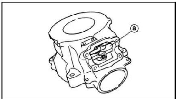
natural_image
Technical line drawing of a mechanical component with labeled part 'a' (no text or symbols beyond label)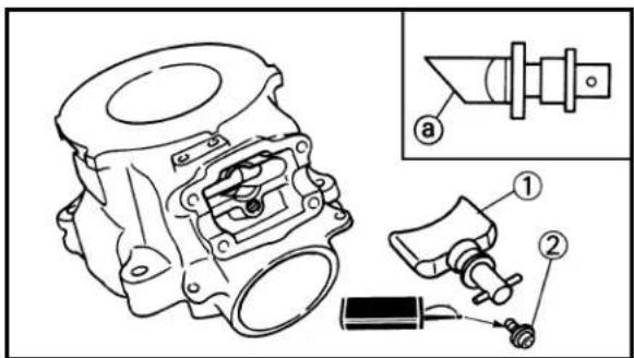
text_image
Technical diagram of a mechanical assembly with labeled parts and an inset view showing a component labeled 'a'.2. Check:
- Piston mark ⓐ
| Piston mark ⓐ (color) |
| A(red) |
| B(orange) |
| C(green) |
3. Combination:
Combine the piston and cylinder by the following chart.
| Cylinder mark Piston mark (color) | |
| A A(red) | |
| B B(orange) | |
| C C (green) | |
NOTE:
When you purchase a cylinder, you cannot designate a specific one. Choose the piston that matches the above chart.
EC474821
Power valve
-
Inspect:
-
Power valve ① Wear/Damage → Replace. Carbon deposits → Remove.
- Valve shaft ②
- Solid bush ③
- Oil seal ④ Wear/Damage → Replace.
EC474901
Power valve hole on cylinder
- Remove:
- Carbon deposits From power valve hole surface ⓐ.
NOTE:
Do not use a sharp instrument. Avoid scratching the aluminum.
EC475000
ASSEMBLY AND INSTALLATION
EC475181
Power valve
- Install:
- Power valve ① - Bolt (power valve) ②

NOTE:
Install the power valve at cut-away faced ⓐ for down side.

flowchart
graph TD
    A["④ New"] --> B["③"]
    A --> C["②"]
    A --> D["①"]
    A --> E["⑦"]
    A --> F["①"]
    A --> G["②"]
    A --> H["③"]
    I["⑤"] --> J["⑥"]
    K["⑧"] --> L["①"]
    M["④ New"] --> N["④"]
    style A fill:#f9f,stroke:#333
    style I fill:#f9f,stroke:#333

text_image
Technical diagram of a mechanical component with numbered parts for identification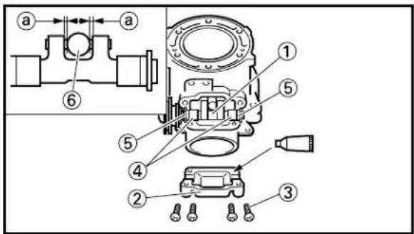
text_image
Technical diagram of a mechanical assembly with numbered components and directional arrows indicating motion or flow.2. Install:
- Solid bush①
- Oil seal ②
- Plain washer ③
- Circlip ④ New
- Valve pulley ⑤
- Screw (valve pulley) ⑥
4 Nm (0.4 m·kg, 2.9 ft·lb)
To valve shaft ⑦.
NOTE:
Apply the lithium soap base grease on the valve shaft and oil seal lip.
- Lock the pulley holding screw using an appropriate wire around the groove on the valve pulley.
4. Install:
- Valve shaft ①
- Valve cover ②
- Screw (valve cover) ③
4 Nm (0.4 m·kg, 2.9 ft·lb)
NOTE:
• Install the valve shaft so that its pulley faces left of the chassis for the left cylinder and right of the chassis for the right cylinder.
- When installing the valve shaft into the cylinder, lightly touch the solid bush ④ with the oil seal ⑤ and provide an equal gap ⑥ for the power valve ⑦ and valve shaft.
- Clean the contacting surface of the valve cover and cylinder before applying the sealant.

Quick gasket®
ACC-YAMAB-ON-D4
YAMAHA Bond No.4
90890-05143
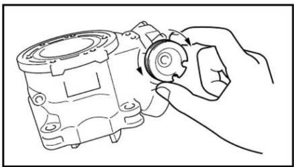
natural_image
Line drawing of a hand turning a mechanical component with arrows indicating rotation (no text or symbols)
text_image
Technical diagram showing a mechanical assembly with labeled parts, including a ring and a base component.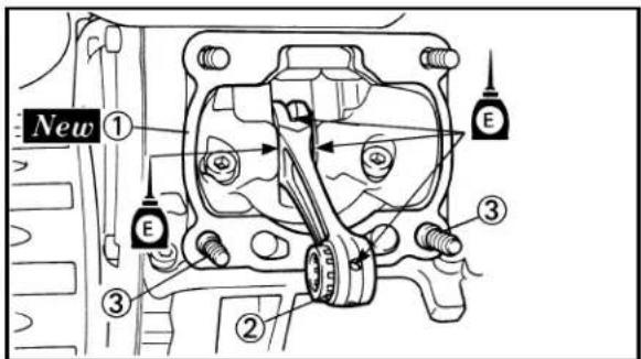
text_image
New ① ② ③ ④ ⑤ E
text_image
CASE a5. Check:
- Power valve smooth movement Unsmooth movement → Repair or replace.
EC475271
Piston ring and piston
1. Install:
- Piston ring ①
NOTE:
• Take care not to scratch the piston or damage the piston ring by expanding it more than necessary.
- Install the piston ring with its mark "N" upward.
- Align the piston ring gap with the pin ②.
• After installing the piston ring, check the smooth movement of it.
2. Install:
• Gasket (cylinder) ① New
- Small end bearing ②
- Dowel pin ③
NOTE:
Apply the engine oil on the bearing (crankshaft and connecting rod) and connecting rod big end washers.
CAUTION:
Install the gasket with the letter "CASE" ⓐ on it toward the crankcase.

text_image
New ① ② ③ ④
text_image
Technical diagram of a piston-cylinder assembly with labeled parts ②, ③, and b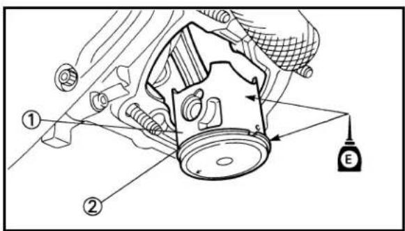
text_image
Technical diagram of a mechanical assembly with labeled parts and directional arrows indicating motion or force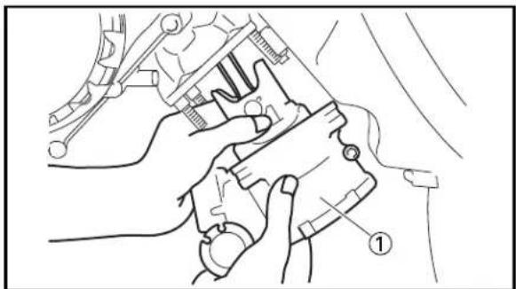
natural_image
Line drawing of hands using a tool to adjust or install a mechanical component (no text or symbols visible)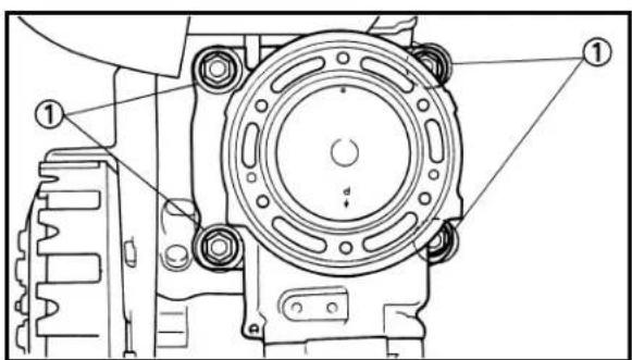
text_image
Technical diagram of a mechanical component with numbered parts and labeled features3. Install:
- Piston ①
- Piston pin ②
- Piston pin clip ③ New
NOTE:
- The arrow ⓐ on the piston dome must point to exhaust side.
- Before installing the piston pin clip, cover the crankcase with a clean rag to prevent the piston pin clip from falling into the crankcase cavity.
CAUTION:
- When installing the piston pin clip, use the hand so that it may not be distorted.
- Do not allow the clip open ends to meet the piston pin slot ⑥.
EC475351
Cylinder head and cylinder
- Apply:
- Engine oil
To piston ①, piston ring ② and cylinder inner surface.
- Install:
- Cylinder ①
CAUTION:
Make sure the piston ring is properly positioned. Install the cylinder with one hand while compressing the piston ring with the other hand.
NOTE:
After installing, check the smooth movement of the piston.
- Install:
- Nut (cylinder) ①
20 Nm (2.0 m·kg, 14 ft·lb)
NOTE:
Tighten the nuts in stages, using a crisscross pattern.
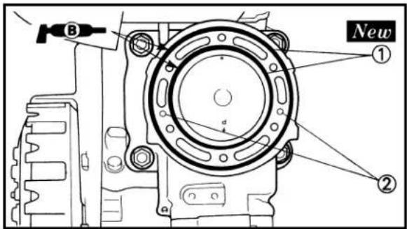
text_image
B New ① ②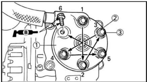
text_image
Technical diagram of a mechanical assembly with numbered components and labeled parts-
Install:
-
O-ring ① New
- Dowel pin ②
NOTE:
Apply the lithium soap base grease on the O-rings.
-
Install:
-
Cylinder head ①
• Copper washer ② - Bolt (cylinder head) ③
11 Nm (1.1 m·kg, 8.0 ft·lb)
NOTE:
- Apply the lithium soap base grease on the thread and contact surface of the bolt (cylinder head).
- Tighten the bolts (cylinder head) in stage, using a crisscross pattern.
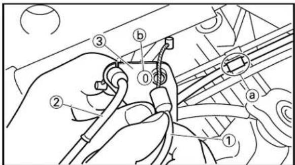
text_image
Technical diagram showing mechanical assembly steps with numbered components and labeled parts
text_image
Technical diagram showing a mechanical assembly with numbered components, likely illustrating a turning or disassembly process.-
Install:
-
YPVS cable 2, 4 (open side) ①
- YPVS cable 1, 3 (close side) ②
To cable stay ③.
NOTE:
Install the open side cables (sleeve ⓐ cables) to the "0" marked Ⓑ side of the cable stay.
-
Connect:
-
YPVS cable 2, 4 (open side) ①
- YPVS cable 1, 3 (close side) ②
To valve pulley ③.
NOTE:
Connect the silver cables to the left side cylinder and the black cables to the right cylinder. Refer to "CABLE ROUTING DIAGRAM" section in the CHAPTER 2.
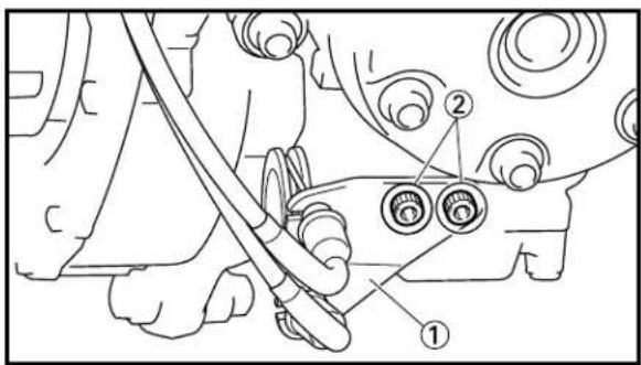
text_image
Technical diagram showing mechanical assembly with labeled parts ① and ②, likely for assembly or maintenance instructions.8. Install:
- Cable stay ①
- Bolt (cable stay) ②
7 Nm (0.7 m·kg, 5.1 ft·lb)
9. Adjust:
- YPVS cable
Refer to "YPVS OPEN SIDE CABLE ADJUSTMENT" and "YPVS CLOSE SIDE CABLE ADJUSTMENT" section in the CHAPTER 3.

text_image
Technical diagram showing mechanical assembly with numbered components, likely illustrating a valve or pump mechanism.10. Install:
- Spark plug ① 19 Nm (1.9 m·kg, 13 ft·lb)
- Spark plug cap ②
- Radiator hose 3 ③
2 Nm (0.2 m·kg, 1.4 ft·lb)
- Radiator hose 4 ④
2 Nm (0.2 m·kg, 1.4 ft·lb)
EC4A0000
CLUTCH
EC4A8000
CLUTCH PLATE AND FRICTION PLATE

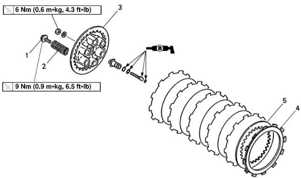
text_image
6 Nm (0.6 m·kg, 4.3 ft·lb) 9 Nm (0.9 m·kg, 6.5 ft·lb)Extend of removal: ① Clutch plate and friction plate removal
| Extend of removal Order Part name Q'ty Remarks | ||||
| Preparation for Lower cowl Refer to “COWLING, SEAT AND removal FUEL TANK” section. | CLUTCH PLATE AND FRICTION PLATE REMOVAL | |||
| 1 | 1 Screw (clutch spring) 62 Clutch spring 63 Pressure plate 14 Friction plate 65 Clutch plate 5 | |||
EC4A8200
CLUTCH HOUSING AND PUSH ROD
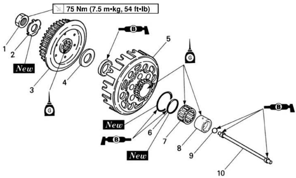
text_image
75 Nm (7.5 m•kg, 54 ft•lb) 1 2 New 3 4 G B 5 G New 6 7 8 9 New 10Extend of removal: ① Clutch housing removal ② Push rod removal
| Extend of removal Order Part name Q'ty Remarks | ||||
| CLUTCH HOUSING AND PUSH ROD REMOVAL | Use special tool.Refer to “REMOVAL POINTS”. | |||
 | 1 Nut (clutch boss) 12 Lock washer 13 Clutch boss 14 Plain washer 15 Clutch housing 16 O-ring7 Bearing8 Spacer 19 Ball10 Push rod | |||

text_image
A ① ② ③ ④
text_image
B ① ② ③ ⑤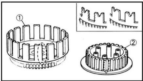
text_image
Technical diagram showing gear meshing with labeled components and corresponding cross-sectional views
text_image
Technical diagram showing hands operating a gear mechanism with labeled parts ① and ②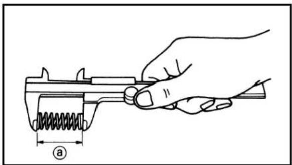
natural_image
Line drawing of a hand adjusting a spring-loaded mechanical component (no text or symbols)EC4A3000
REMOVAL POINTS
EC483211
Clutch boss
-
Remove:
-
Nut ①
- Lock washer ②
- Clutch boss ③
NOTE:
Straighten the lock washer tab and use the clutch holding tool ④, ⑤ to hold the clutch boss.

Clutch holding tool:
YM-91042 .....④
90890-04086 .....⑤
A For USA and CDN
B Except for USA and CDN
EC4A4000
INSPECTION
EC484100
Clutch housing and boss
-
Inspect:
-
Clutch housing ①
Cracks/Wear/Damage → Replace. - Clutch boss ②
Scoring/Wear/Damage → Replace.
EC4A4100
Clutch housing
- Check:
• Circumferential play
Free play exists → Replace.
- Gear teeth ⓐ
Wear/Damage → Replace.
- O-ring ①
Damage → Replace.
EC484400
Clutch spring
-
Measure:
-
Clutch spring free length ⓐ
Out of specification → Replace springs as a set.

Clutch spring free length:
Standard
30.6 mm (1.205 in) 29.6 mm (1.165 in)
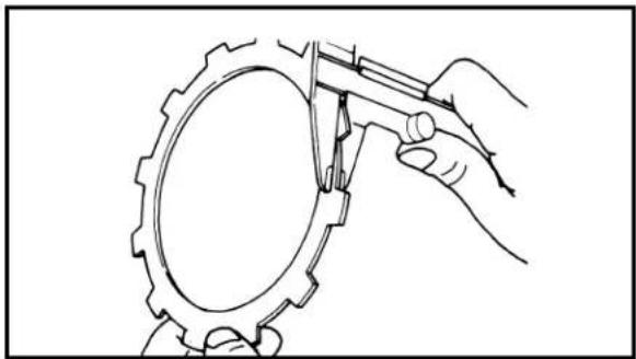
natural_image
Line drawing of a hand using a tool to measure a circular gear component (no text or symbols)
text_image
Diagram showing two labeled hands operating a tool on a textured object, marked with numbers ① and ②.EC484500
Friction plate
1. Measure:
- Friction plate thickness
Out of specification → Replace friction plate as a set.
Measure at all four points.

Friction plate thickness:
Standard
2.9\~3.1 mm 2.7 mm
(0.114\~0.122 in) (0.106 in)
EC484600
Clutch plate
1. Measure:
- Clutch plate warpage
Out of specification → Replace clutch plate as a set.
Use a surface plate ① and thickness gauge ②.

Warp limit:
0.1 mm (0.004 in)
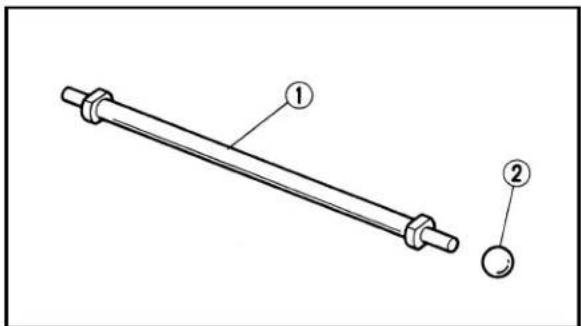
text_image
Technical diagram of a mechanical rod with labeled parts ① and ②, showing two different ends.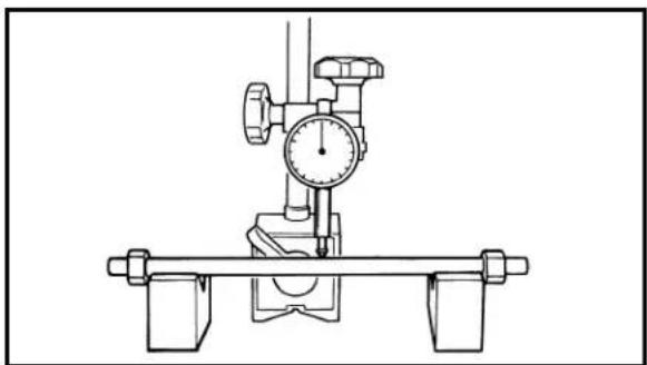
natural_image
Technical line drawing of a mechanical measurement device with dial and support components (no text or symbols)EC4A4301
Push rod
1. Inspect:
- Push rod ①
- Ball ②
Wear/Damage/Bend → Replace.

Bending limit:
0.2 mm (0.008 in)
NOTE:
The bending value is shown by one half of the dial gauge reading.
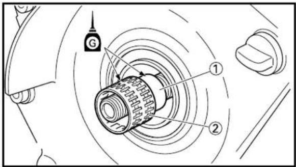
text_image
Technical diagram of a mechanical assembly with labeled parts and directional arrows indicating motion or flow.
text_image
① New ②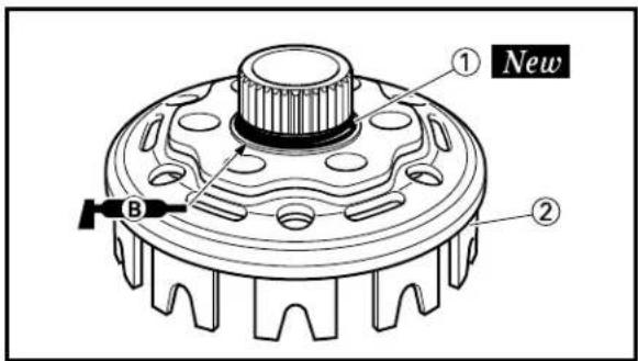
text_image
① New ② B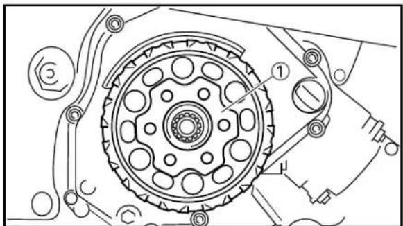
text_image
Technical diagram of a mechanical gear assembly with labeled components and parts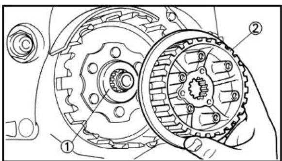
text_image
Technical diagram of a mechanical gear assembly with labeled parts, showing hand operating a gear mechanism.EC4A5000
ASSEMBLY AND INSTALLATION
EC4A5213
Clutch
-
Install:
-
Spacer 1 ①
- Bearing ②
NOTE:
Apply the transmission oil on the spacer 1 and bearing.
- Install:
- O-ring ① New
NOTE:
Apply the lithium soap base grease on the O-ring.
- Install:
- O-ring ① New
To clutch housing ②.
NOTE:
Apply the lithium soap base grease on the O-ring.
- Install:
- Clutch housing ①
-
Install:
-
Plain washer ①
- Clutch boss ②

text_image
A ① ② ③ ④
text_image
B ① New ② ④ a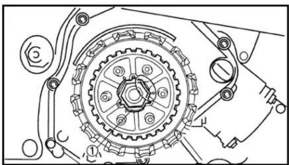
natural_image
Mechanical gear assembly diagram showing meshing gears and shafts (no text or labels)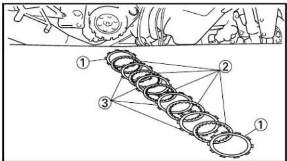
text_image
Technical diagram showing mechanical assembly with numbered components and connection points-
Install:
-
Lock washer ① New
- Nut (clutch boss) ②
75 Nm (7.5 m·kg, 54 ft·lb)
NOTE:
Use the clutch holding tool ③, ④ to hold the clutch boss.
CAUTION:
Align the projections on the lock washer with the holes ⓐ in the clutch boss.

Clutch holding tool:
YM-91042 ③
90890-04086 .....④
A For USA and CDN
B Except for USA and CDN
-
Bend the lock washer ① tab.
-
Install:
-
Friction plate (yellow) ①
- Clutch plate ②
- Friction plate (brown) ③
NOTE:
• Install the clutch plates and friction plates alternately on the clutch boss, starting with a friction plate and ending with a friction plate.
- Yellow colored friction plates are used for the first and final.
- This machine is equipped with a dry type clutch. Be sure to clean with solvent or replace if grease or oil contacts either clutch or friction plates.
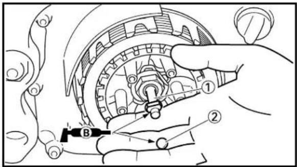
text_image
Technical diagram showing mechanical assembly with labeled parts and directional arrows
text_image
Technical diagram of a mechanical assembly with labeled parts, showing gear and rotor components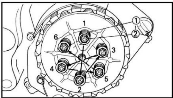
text_image
Technical diagram of a mechanical gear assembly with numbered components and labeled parts
text_image
Technical diagram of a mechanical assembly with labeled parts and directional arrows indicating movement or assembly.
text_image
Technical diagram of a mechanical component with numbered parts and labeled features9. Install:
- Push rod ①
- Ball ②
NOTE:
Apply the lithium soap base grease on the push rod and ball.
10. Install:
- Pressure plate ①
NOTE:
Align the arrow marks ⓐ on the pressure plate the arrow marks ⓑ on the clutch boss.
11. Install:
- Clutch spring ①
- Screw (clutch spring) ②
9 Nm (0.9 m·kg, 6.5 ft·lb)
NOTE:
Tighten the screws in stages, using a criss-cross pattern.
12.Check:
- Push lever position
Push the push lever ① upward until it stops. With the push lever in this position, the rear edge ⓐ of the push lever should be aligned with the center of the push lever installation bolt ②.
Not aligned → Adjust.
13.Adjust:
- Push lever position
| Push lever position adjustment steps:Loosen the locknut 1.Turn the adjuster 2 to align the rear edge of the push lever with the center of the push lever installation bolt.Tighten the locknut. | |
 | Locknut:6 Nm (0.6 m·kg, 4.3 ft·lb) |
EC4D0002
PRIMARY DRIVEN GEAR, PRIMARY DRIVE GEAR AND BALANCER SHAFT
EC4D8000
PRIMARY DRIVEN GEAR


text_image
11 Nm (1.1 m•kg, 8.0 ft•lb) New BExtend of removal: ① Primary driven gear removal
| Extend of removal Order Part | name Q'ty Remarks | |||
| Preparation for Cowling removal GUIDE, SEAT | Refer to “COWLING, INDUCTION AND FUEL TANK”Clutch Refer to “CLUTCH” section.Drain the transmission oil. Refer to “TRANSMISSION OIL REPLACEMENT” section in the CHAPTER 3. | section. | ||
| 1 | Crankcase cover (right) | 1 | ||
| 2 | Primary driven gear | 1 | ||
| 3 | Oil pump drive gear | 1 | ||
| 4 | Thrust plate | 1 | ||
EC4D8100
PRIMARY DRIVE GEAR AND BALANCER SHAFT
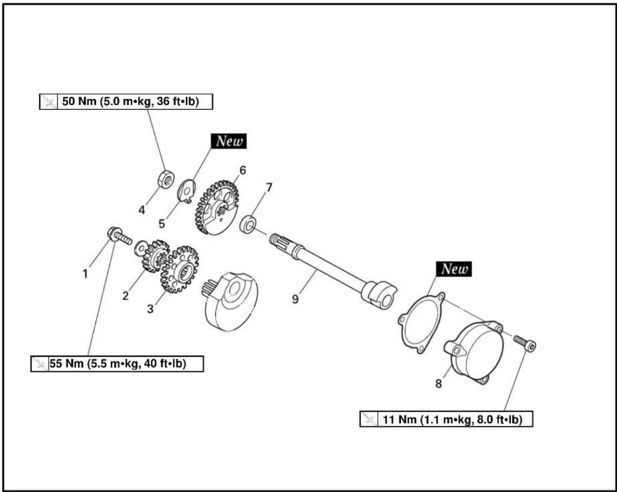
text_image
50 Nm (5.0 m•kg, 36 ft•lb) New 1 2 3 4 5 6 7 9 New 55 Nm (5.5 m•kg, 40 ft•lb) 11 Nm (1.1 m•kg, 8.0 ft•lb)Extend of removal: ① Primary drive gear removal
② Balancer shaft removal
| Extend of removal Order Part name Q'ty Remarks | |||
 | PRIMARY DRIVE GEAR AND BALANCER SHAFT REMOVAL1 Bolt (primary drive gear) 12 Primary drive gear 13 Balancer drive gear 14 Nut (balancer weight gear) 15 Lock washer 16 Balancer weight gear 17 Collar 18 Crankcase cover (left) 19 Balancer shaft 1 | Refer to “REMOVAL POINTS”. | |
PRIMARY DRIVEN GEAR, PRIMARY DRIVE GEAR AND BALANCER SHAFT
ENG

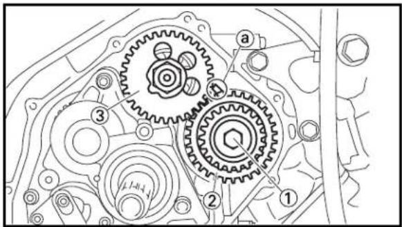
text_image
Technical diagram of a mechanical gear assembly with numbered components and labeled parts
text_image
Technical diagram of a mechanical gear assembly with numbered components and labeled parts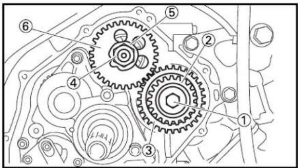
text_image
Technical diagram of a mechanical gear assembly with numbered components for identificationEC4D3000 REMOVAL POINTS
EC4D3101
Primary drive gear and balancer weight gear
- Loosen:
- Bolt (primary drive gear) ①
NOTE:
Place an aluminum plate ① between the teeth of the balancer drive gear ② and balancer weight gear ③.
- Loosen:
- Nut (balancer weight gear) ①
NOTE:
Straighten the lock washer ② tab and place an aluminum plate ③ between the teeth of the balancer drive gear ④ and balancer weight gear ⑤.
-
Remove:
-
Bolt (primary drive gear) ①
• Primary drive gear ② - Balancer drive gear ③
- Nut (balancer weight gear) ④
- Lock washer ⑤
- Balancer weight gear ⑥
NOTE:
It may sometimes happens that the primary drive gear and balancer drive gear are fitted too tight as in force fitting. In that case, use a general gear puller to remove them without too much force on the crankshaft.

text_image
Technical diagram of three types of gear components with numbered labelsEC4D4000
INSPECTION
EC4D4100
Primary drive gear, primary driven gear and oil pump drive gear
-
Inspect:
-
Primary drive gear ①
• Primary driven gear ② - Oil pump drive gear ③
Wear/Damage → Replace.
PRIMARY DRIVEN GEAR, PRIMARY DRIVE GEAR AND BALANCER SHAFT
ENG


text_image
Diagram showing two gear meshing gears with labeled components, numbered ① and ②.EC4D4200
Balancer weight gear and balancer drive gear
-
Inspect:
-
Balancer weight gear ①
- Balancer drive gear ② Wear/Damage → Replace.
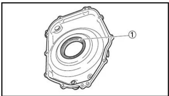
natural_image
Technical line drawing of a mechanical component with concentric rings and mounting holes (no text or symbols)EC4D4300
Crankcase cover (right)
-
Inspect:
-
Contacting surface Scratches → Replace.
- Crankcase cover (right) Cracks/Damage → Replace.
- Oil seal ① Wear/Damage → Replace.

natural_image
Technical line drawing of a mechanical component with labeled part (1), no text or symbols presentEC4D4500
Balancer shaft
-
Inspect:
-
Balancer shaft ① Bend/Wear/Damage → Replace.

text_image
Technical diagram showing mechanical assembly with numbered components and a hand holding a bearingEC4D5000
ASSEMBLY AND INSTALLATION
EC4D5130
Balancer shaft and primary drive gear
-
Install:
-
Balancer shaft ①
- Collar ②
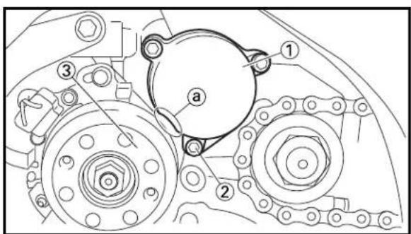
text_image
Technical diagram of a mechanical gear assembly with numbered components and labeled parts- Install:
• Gasket [crankcase cover (left)] New
• Crankcase cover (left) ①
- Bolt [crankcase cover (left)] ②
11 Nm (1.1 m·kg, 8.0 ft·lb)
NOTE:
Install the gasket and crankcase cover (left) with their recesses ① facing the rotor ③.
PRIMARY DRIVEN GEAR, PRIMARY DRIVE GEAR AND BALANCER SHAFT
ENG

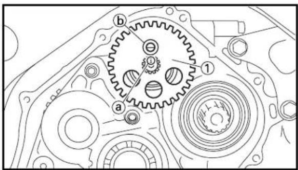
text_image
Technical diagram of a mechanical gear assembly with labeled components (a, b, 1, 2)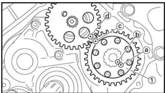
text_image
Technical diagram of a mechanical gear assembly with labeled components a, b, c, d and numbered parts 1, 2, 3, 4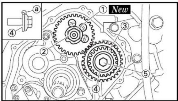
text_image
① New ② ③ ④ ⑤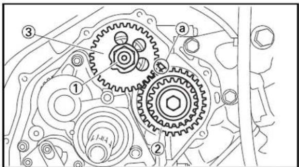
text_image
Technical diagram of a mechanical gear assembly with numbered components and labeled parts
natural_image
Mechanical gear assembly diagram showing interconnected gears and shafts (no text or labels)3. Install:
- Balancer weight gear ①
NOTE:
Align the punch mark ⓐ on the balancer shaft with the hole ⓑ of the balancer weight gear.
4. Install:
- Balancer drive gear ①
NOTE:
Align the punch marks, ⓐ (balancer drive gear) with Ⓑ (crankshaft) and Ⓐ (balancer drive gear) with ⓔ (balancer weight gear) as shown.
5. Install:
- Lock washer ① New
- Nut (balancer weight gear) ②
- Primary drive gear ③
- Plain washer ④
- Bolt (primary drive gear) ⑤
NOTE:
Install the plain washer with its chamfered portion ⓐ toward you.
6. Tighten:
- Nut (balancer weight gear) ①
50 Nm (5.0 m·kg, 36 ft·lb)
NOTE:
Place an aluminum plate ① between the teeth of the balancer drive gear ② and balancer weight gear ③.
7. Bend the lock washer ① tab.
PRIMARY DRIVEN GEAR, PRIMARY DRIVE GEAR AND BALANCER SHAFT
ENG

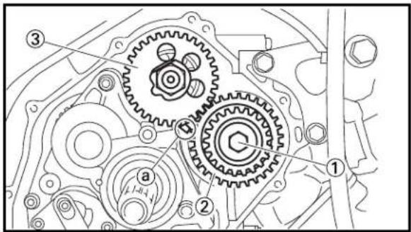
text_image
Technical diagram of a mechanical gear assembly with numbered components and labeled parts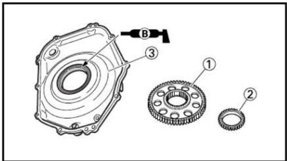
text_image
Technical diagram of a mechanical gear assembly with labeled parts and component B
text_image
Technical diagram of a mechanical gear assembly with labeled components and an inset showing a gear mechanism with dimension 'a'.
text_image
Technical diagram of a mechanical gear assembly with numbered components for identification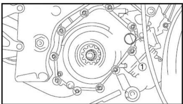
natural_image
Mechanical gear assembly diagram showing interconnected components (no text or labels)- Tighten:
- Bolt (primary drive gear) ①
55 Nm (5.5 m·kg, 40 ft·lb)
NOTE:
Place an aluminum plate ① between the teeth of the balancer drive gear ② and balancer weight gear ③.
EC4D5212
Primary driven gear
- Install:
• Primary driven gear ①
- Oil pump drive gear ②
To crankcase cover (right) ③.
NOTE:
Apply the lithium soap base grease on the oil seal lip.
-
Install:
-
Thrust plate ①
- Dowel pin ②
• Gasket [crankcase cover (right)] ③ New
NOTE:
Install the thrust plate with its larger diameter side ⓐ toward the transmission.
- Install:
- Crankcase cover (right) ①
NOTE:
Mesh the primary drive gear ② with the primary driven gear ③, and the oil pump drive gear ④ with the oil pump driven gear ⑤ by turning the rotor.
- Install:
- Bolt [crankcase cover (right)] ①
11 Nm (1.1 m·kg, 8.0 ft·lb)
NOTE:
Tighten the bolts in stages, using a crisscross pattern.
EC4F0000
SHIFT SHAFT

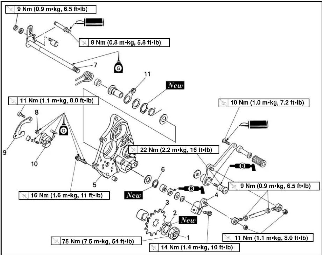
text_image
9 Nm (0.9 m·kg, 6.5 ft·lb) 8 Nm (0.8 m·kg, 5.8 ft·lb) 11 Nm (1.1 m·kg, 8.0 ft·lb) 22 Nm (2.2 m·kg, 16 ft·lb) 10 Nm (1.0 m·kg, 7.2 ft·lb) 9 Nm (0.9 m·kg, 6.5 ft·lb) 11 Nm (1.1 m·kg, 8.0 ft·lb) 75 Nm (7.5 m·kg, 54 ft·lb) 14 Nm (1.4 m·kg, 10 ft·lb)Extend of removal: ① Shift shaft removal ② Stopper lever removal
| Extend of removal Order Part name Q'ty Remarks | |||||
| Preparation for Crankcase cover (right) Refer to “PRIMARY DRIVEN GEAR,removal PRIMARY DRIVE GEAR AND BALANCER SHAFT” section. | |||||
 | 1 Nut (drive sprocket) 12 Lock washer 1 Refer to “REMOVAL POINTS”.3 Drive sprocket4 Shift arm5 Transmission housing6 Circlip7 Shift shaft8 Roller9 Shift guide10 Shift lever assembly11 Stopper lever | 1Refer to “REMOVAL POINTS”.1111 | |||
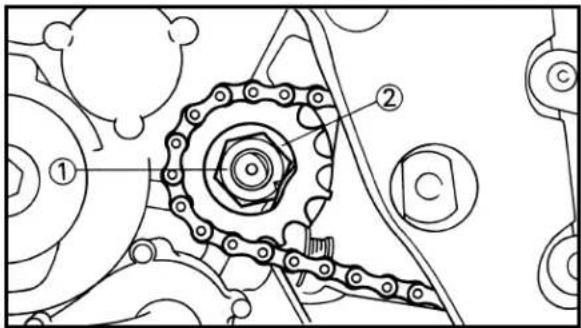
text_image
Technical diagram of a mechanical gear assembly with labeled components ①, ②, and C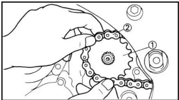
text_image
Technical diagram showing a hand assembling a mechanical gear with numbered components labeled ①, ②, and ③.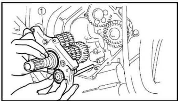
natural_image
Mechanical assembly diagram showing hands operating a gear mechanism within a vehicle (no text or labels)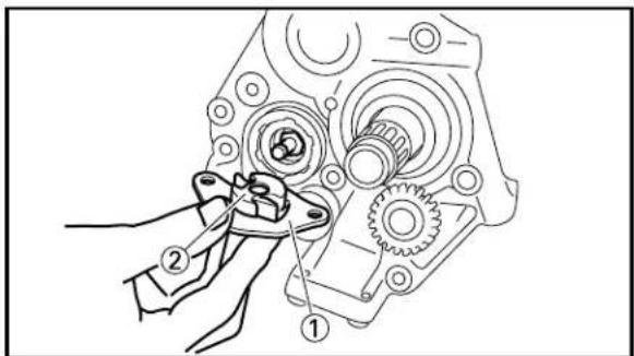
text_image
Technical diagram showing mechanical assembly with numbered parts labeled ①, ②, and ③
text_image
Technical diagram of a mechanical component with labeled parts 1, 2, and aEC4F3000
REMOVAL POINTS
EC4F3100
Drive sprocket
-
Remove:
-
Nut (drive sprocket) ①
- Lock washer ②
NOTE:
- Straighten the lock washer tab.
-
Loosen the nut while applying the rear brake.
-
Remove:
-
Drive sprocket ①
- Drive chain ②
NOTE:
Remove the drive sprocket together with the drive chain.
EC4F3201
Transmission housing
- Remove:
• Bolt (transmission housing)
• Transmission housing ①
NOTE:
Remove the transmission housing together with the transmission, shift cam, shift fork and shift shaft.
EC4C3101
Shift guide and shift lever assembly
-
Remove:
-
Bolt (shift guide)
- Shift guide ①
- Shift lever assembly ②
NOTE:
The shift lever assembly is disassembled at the same time as the shift guide.
EC4F3401
Stopper lever
-
Remove:
-
Stopper lever assembly ①
- Torsion spring ②
- Plain washer
NOTE:
Remove the stopper lever assembly with its roller aligning with the top ⓐ of the segment.

text_image
Technical diagram of a mechanical component with numbered parts labeled ①, ②, and ③.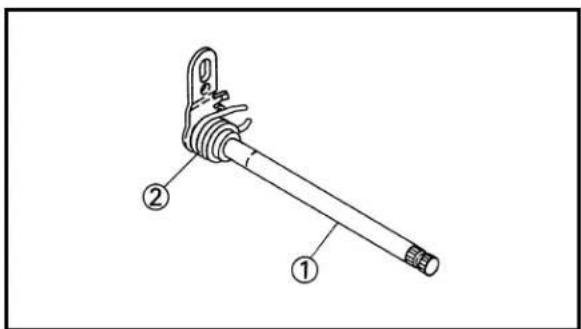
text_image
Technical diagram of a mechanical lever with labeled parts ① and ②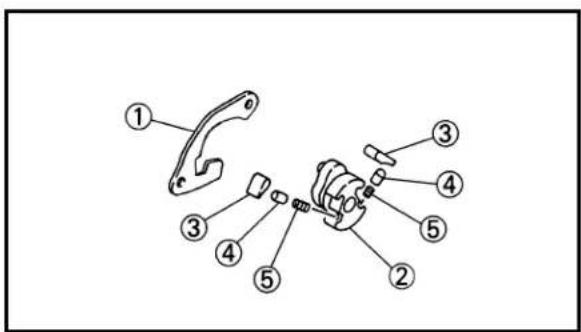
text_image
Technical diagram of a mechanical assembly with numbered parts for identification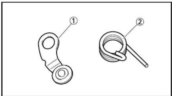
natural_image
Technical line drawing of two mechanical components, one with a circular end and labeled part 1, the other with a coiled spring and labeled part 2 (no text or symbols present)
text_image
① ② ③ New ④ a-
Remove:
-
Circlip ①
- Plain washer ②
- Stopper lever ③
EC4F4000
INSPECTION
EC4B4400
Shift shaft
-
Inspect:
-
Shift shaft ①
Bend/Damage → Replace. - Spring ②
Broken → Replace.
EC4C4100
Shift guide and shift lever assembly
-
Inspect:
-
Shift guide ①
- Shift lever ②
- Pawl ③
- Pawl pin ④
- Spring ⑤
Wear/Damage → Replace.
EC4B4500
Stopper lever
-
Inspect:
-
Stopper lever ①
Wear/Damage → Replace. - Torsion spring ②
Broken → Replace.
EC4F5000
ASSEMBLY AND INSTALLATION
EC4F5100
Stopper lever
-
Install:
-
Stopper lever ①
- Plain washer ②
- Circlip ③ New
To collar ④.
NOTE:
Be sure the circlip sharp-edged corner ⓐ is positioned opposite side to the plain washer.
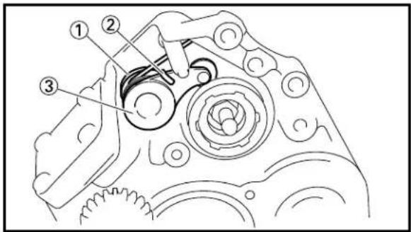
text_image
Technical diagram of a mechanical component with numbered parts labeled ①, ②, and ③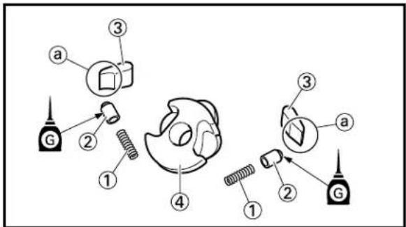
text_image
Diagram showing labeled parts of a mechanical assembly with numbered annotations
text_image
Technical diagram of a mechanical clamp or bracket with labeled parts ① and ②
text_image
Technical diagram of a mechanical assembly with labeled parts and tool indicator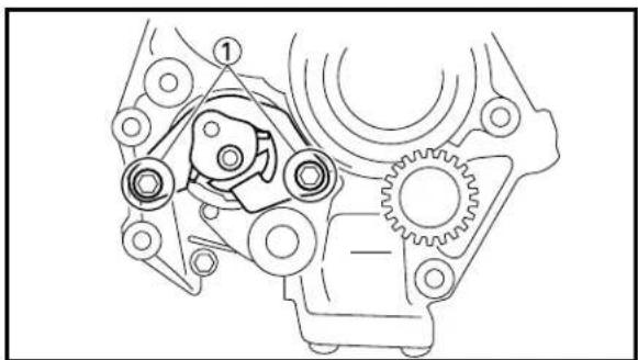
natural_image
Mechanical gear assembly diagram showing interconnected components (no text or labels)2. Install:
- Plain washer ①
- Torsion spring ②
- Stopper lever assembly ③
EC4F5202
Shift guide and shift lever assembly
1. Install:
- Spring ①
- Pawl pin ②
- Pawl ③
To shift lever ④.
NOTE:
- When installing the pawl into the shift lever, make sure the chamfered side ⓐ face the pawl pin side.
- Apply the transmission oil on the pawl pin.
2. Install:
- Shift lever assembly ①
To shift guide ②.
3. Install:
- Shift lever assembly ①
- Shift guide ②
NOTE:
- The shift lever assembly is installed at the same time as the shift guide.
- Apply the transmission oil on the bolt (segment) shaft.
4. Install:
- Bolt (shift guide) ①
11 Nm (1.1 m·kg, 8.0 ft·lb)

text_image
Technical diagram showing mechanical assembly steps with labeled components and directional arrows
text_image
① ② a ② New ① ③
text_image
Technical diagram of a mechanical assembly with numbered components and directional arrows indicating motion or assembly.EC4F5302
Shift shaft
1. Install:
- Roller ①
- Torsion spring ②
- Shift shaft ③
NOTE:
Apply the transmission oil on the roller and shift shaft.
2. Install:
- Plain washer ①
- Circlip ② New
To shift shaft ③.
NOTE:
Be sure the circlip sharp-edged corner ⓐ is positioned opposite side to the plain washer.
3. Check:
- Shift lever position
Checking steps:
- Attach the collar (with supplying parts) ② onto the roller ①.
- Check the shift lever position. Gaps ⓐ and ⓑ are not equal → Adjust.
4. Adjust:
- Shift lever position
Adjusting steps:
- Loosen the locknut ③.
- Turn the adjuster ④ in or out.
- Tighten the locknut.

Locknut:
9 Nm (0.9 m·kg, 6.5 ft·lb)
- Remove the collar.
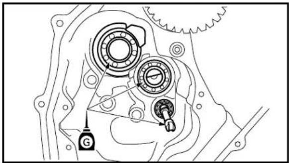
natural_image
Mechanical gear assembly diagram showing internal components and a labeled component (G), no text or symbols present.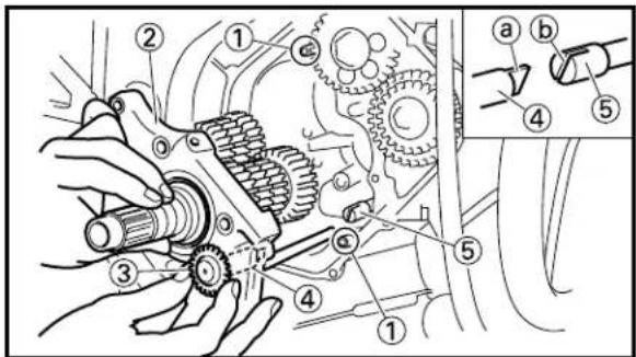
text_image
Technical diagram of a mechanical assembly with numbered components and an inset showing a close-up of a tool interacting with a gear mechanism.
text_image
Technical diagram of a mechanical gear assembly with labeled components and directional arrows indicating motion or assembly.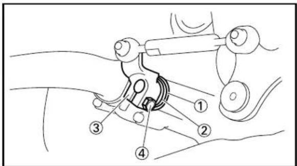
text_image
Technical diagram of a mechanical assembly with numbered components, likely illustrating a linkage or mounting mechanism.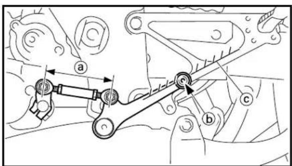
text_image
Technical diagram showing mechanical linkage with labeled parts a, b, and cEC4F5411 Transmission housing
1. Apply:
- Transmission oil
On the bearing (crankcase lower) and impeller shaft.
2. Install:
- Dowel pin ①
• Transmission housing ②
NOTE:
When installing the transmission housing, turn the oil pump driven gear ③ until the key end ④ of the oil pump gear shaft ④ is in the recess ⑤ of the impeller shaft ⑤.
3. Install:
- Bolt {transmission housing [L=40 mm (1.57 in)]} ①
T 16 Nm (1.6 mdkg, 11 ftdlb) - Bolt {transmission housing [L=30 mm (1.18 in)]} ②
T 16 Nm (1.6 mdkg, 11 ftdlb)
NOTE:
- Tighten the bolts in stages, using a criss-cross pattern.
- Apply the transmission oil on the thread and contact surface of the bolt (transmission housing).
4. Install:
- Plain washer ①
- Spacer ②
- Shift arm ③
- Bolt (shift arm) ④
T 14 Nm (1.4 mdkg, 10 ftdlb)
NOTE:
- Make sure that the joint rod distance ⓐ is 104.5\~106.5 mm (4.1\~4.2 in).
• Install the shift arm so that the shift pedal center ⓑ is highest without exceeding the inside line Ⓒ of the footrest bracket.

text_image
Technical diagram of a mechanical gear assembly with labeled parts and an inset showing a pin mechanism.
text_image
① New ②EC4F5510
Drive sprocket
-
Install:
-
Drive sprocket ①
- Drive chain ②
NOTE:
• Install the drive sprocket with its depressed side ⓐ facing the engine.
• Install the drive sprocket together with the drive chain.
-
Install:
-
Lock washer ① New
- Nut (drive sprocket) ②
75 Nm (7.5 m·kg, 54 ft·lb)
NOTE:
Tighten the nut while applying the rear brake.
- Bend the lock washer tab to lock the nut.
EC4G0000
WATER PUMP

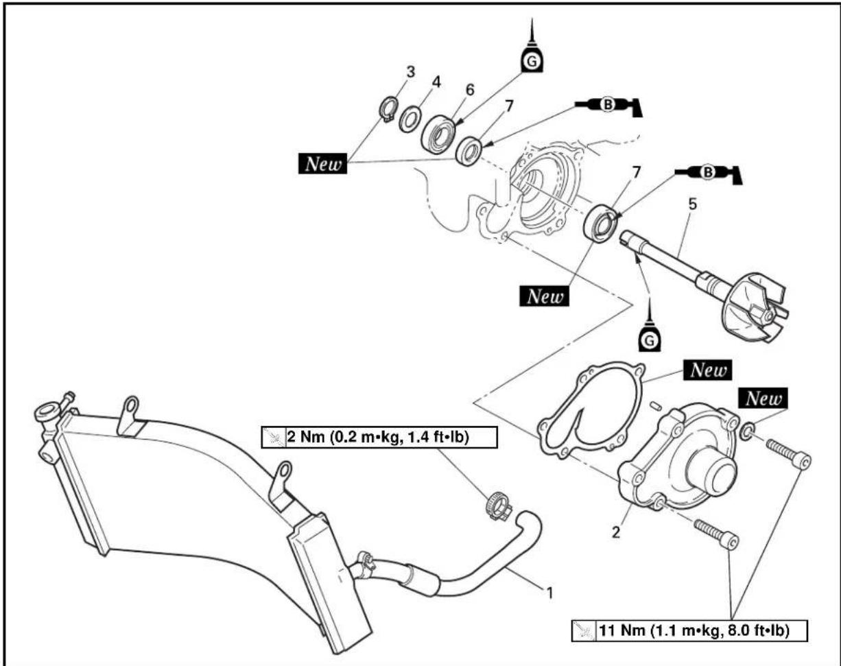
text_image
2 Nm (0.2 m·kg, 1.4 ft·lb) 11 Nm (1.1 m·kg, 8.0 ft·lb)Extend of removal: ① Impeller shaft removal ② Oil seal removal
| Extend of removal Order Part | name Q'ty Remarks | ||||
| Preparation for Cowling removal GUIDE, SEAT | Refer AND FUEL TANK" | WATER PUMP DISASSEMBLY to "COWLING, INDUCTION Drain the cooling water. Refer to Transmission housing Refer to "SHIFT SHAFT" section. | "COOLING WATER REPLACEMENT" section in the CHAPTER 3. | ||
 | 1 | Radiator hose 2 | 1 | Refer to "REMOVAL POINTS". | |
| 2 | Water pump housing cover | 1 | |||
| 3 | Circlip | 1 | |||
| 4 | Plain washer | 1 | |||
| 5 | Impeller shaft | 1 | |||
| 6 | Bearing | 1 | |||
| 7 | Oil seal | 2 | |||
EC4G3000
REMOVAL POINTS
EC4G3210
Oil seal
NOTE:
It is not necessary to disassemble the water pump, unless there is an abnormality such as excessive change in coolant level, discoloration of coolant, or milky transmission oil.

natural_image
Technical line drawing of a mechanical assembly with concentric rings and a labeled component (no text or symbols present)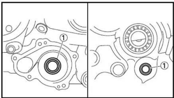
text_image
Technical diagram showing mechanical components with labeled parts, including a numbered callout for detail.
natural_image
Technical line drawing of a mechanical component with labeled part (1), no text or symbols present
natural_image
Technical line drawing of a mechanical assembly with concentric rings and a labeled component (no text or symbols present)- Remove:
- Bearing ①
- Remove:
- Oil seal ①
EC4G4000
INSPECTION
EC444200
Impeller shaft
- Inspect:
- Impeller shaft ① Bend/Wear/Damage → Replace.
Fur deposits → Clean.
EC4H4600
Bearing
- Inspect:
- Bearing ① Rotate inner race with a finger. Rough spot/Seizure → Replace.
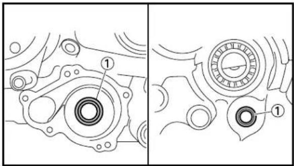
text_image
Technical diagram showing mechanical components with labeled parts, including a numbered callout for detail.
text_image
① ① ① ② ① New B B
natural_image
Technical line drawing of a mechanical assembly with concentric rings and a labeled component (no text or symbols present)
text_image
Technical diagram showing mechanical assembly with labeled component 'B' and numbered parts ① and ②
text_image
Technical diagram showing mechanical assembly with numbered components and a labeled 'New' sectionEC444400
Oil seal
- Inspect:
- Oil seal ①
Wear/Damage → Replace.
EC4G5000
ASSEMBLY AND INSTALLATION
EC4G5120
Oil seal
- Install:
- Oil seal ① New
NOTE:
- Apply the lithium soap base grease on the oil seal lip.
-
Install the oil seal with its manufacture's marks or numbers facing the crankcase ②.
-
Install:
- Bearing ①
NOTE:
Install the bearing by pressing its outer race parallel.
EC4G5203
Impeller shaft
- Install:
- Impeller shaft ①
NOTE:
• Take care so that the oil seal lip is not damaged or the spring does not slip off its position.
- When installing the impeller shaft, apply the lithium soap base grease on the oil seal lip and impeller shaft. And install the shaft while turning it.
-
Install:
-
Plain washer ①
- Circlip ② New
To impeller shaft ③.
NOTE:
Be sure the circlip sharp-edged corner ⓐ is positioned opposite side to the plain washer.
WATER PUMP
ENG

text_image
① ② New ①
text_image
New ① ② ③ ④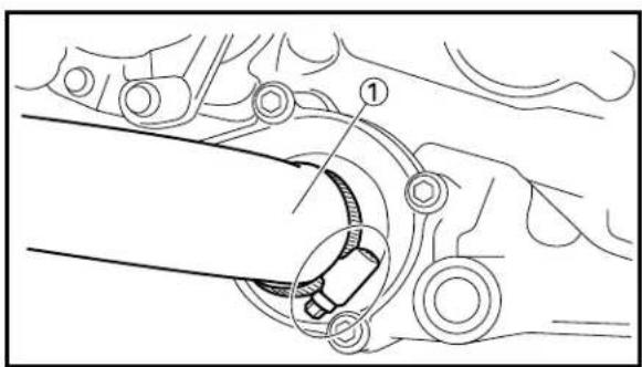
text_image
Technical diagram showing mechanical assembly with labeled component '1' and directional arrows indicating movement or flow.3. Install:
- Dowel pin ①
• Gasket (water pump housing cover) ② New
4. Install:
• Water pump housing cover ①
- Bolt (water pump housing cover) ②
11 Nm (1.1 m·kg, 8.0 ft·lb)
• Copper washer ③ New
• Air bleeding bolt (water pump) ④
11 Nm (1.1 m·kg, 8.0 ft·lb)
5. Install:
- Radiator hose 2 ①
2 Nm (0.2 m·kg, 1.4 ft·lb)
EC4H0000
TRANSMISSION, SHIFT CAM AND SHIFT FORK

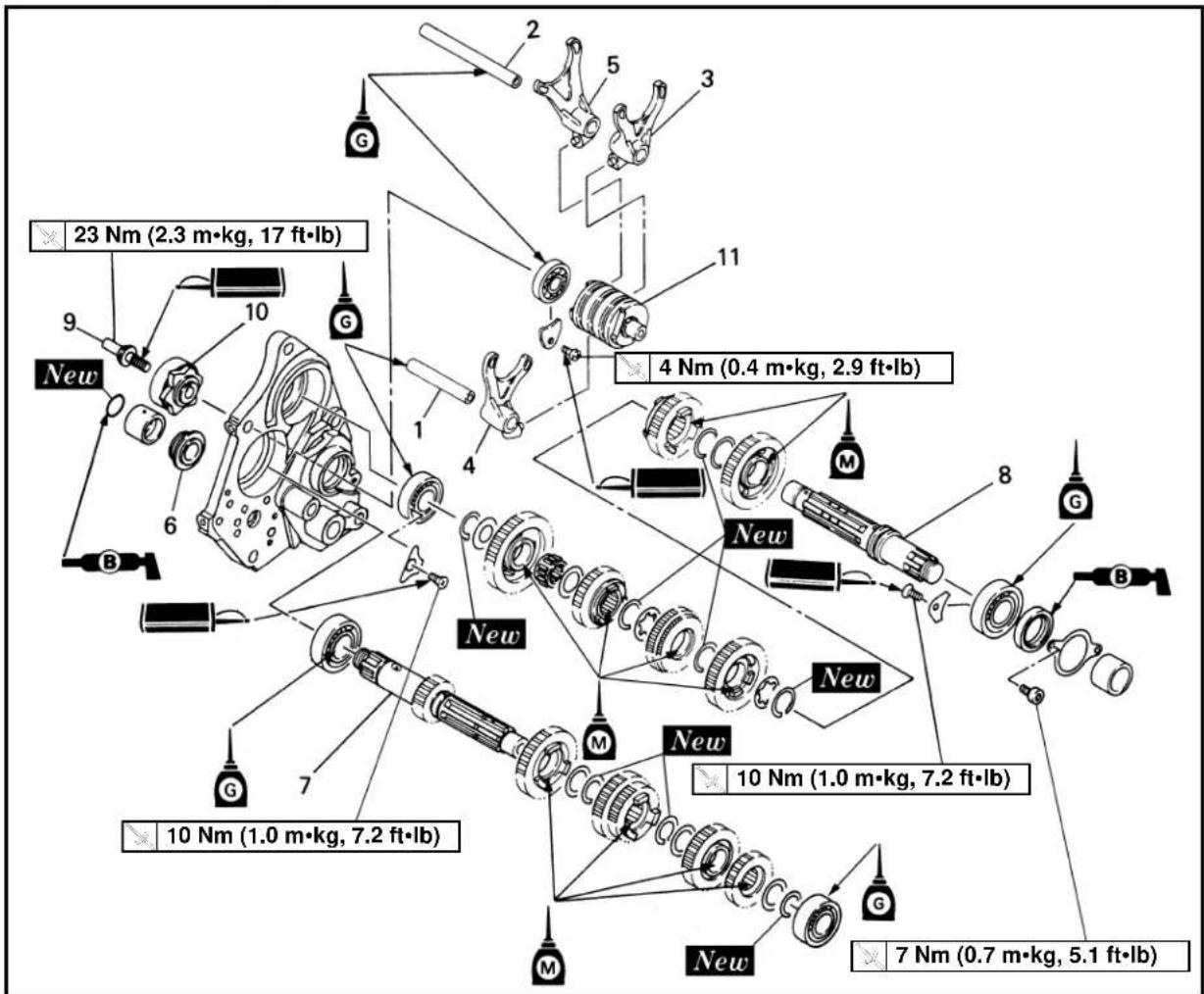
text_image
23 Nm (2.3 m·kg, 17 ft·lb) New 4 Nm (0.4 m·kg, 2.9 ft·lb) 10 Nm (1.0 m·kg, 7.2 ft·lb) 10 Nm (1.0 m·kg, 7.2 ft·lb) 10 Nm (1.0 m·kg, 7.2 ft·lb) 7 Nm (0.7 m·kg, 5.1 ft·lb)| Extend of removal Order Part | name Q'ty Remarks | |||
| Preparation for removal GUIDE, SEAT | AND F | TRANSMISSION, SHIFT CAM AND SHIFT FORK REMOVALCowlingUEL TANK"Transmission housingShift shaft and shift lever assemblyStopper lever | Refer to “COWLING, INDUCTION section.Refer to “SHIFT SHAFT” section. | |

text_image
23 Nm (2.3 m·kg, 17 ft·lb) New 4 Nm (0.4 m·kg, 2.9 ft·lb) 10 Nm (1.0 m·kg, 7.2 ft·lb) 10 Nm (1.0 m·kg, 7.2 ft·lb) 10 Nm (1.0 m·kg, 7.2 ft·lb) 7 Nm (0.7 m·kg, 5.1 ft·lb)Extend of removal:
① Shift fork removal
② Main axle and drive axle removal
③ Shift cam removal
| Extend of removal Order Part name Q'ty Remarks | ||||
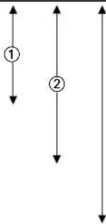 | 1 Guide bar 1 (short) 12 Guide bar 2 (long) 13 Shift fork 1 14 Shift fork 2 15 Shift fork 3 16 Thrust plate 17 Main axle 18 Drive axle 19 Bolt (segment) 110 Segment11 Shift cam | 1 | Refer to “REMOVAL POINTS”.Refer to “REMOVAL POINTS”. | |

text_image
Technical diagram of a mechanical assembly with numbered components labeled ①, ②, and ③.EC4H3000
REMOVAL POINTS
EC4H3210
Transmission
-
Remove:
-
Main axle ①
- Drive axle ②
NOTE:
- Remove the main axle together with the drive axle from the transmission housing ③.
- Remove assembly carefully. Note the position of each part. Pay particular attention to the location and direction of shift forks.

text_image
Technical diagram of a mechanical gear assembly with numbered componentsEC4H3400
Segment
-
Remove:
-
Bolt (segment) ①
- Segment ②
NOTE:
Clamp the shift cam ③ securely in a vise, using soft protecting material ④ to loosen the bolt (segment).
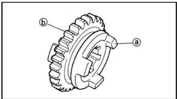
text_image
Technical diagram of a gear assembly with labeled parts a and bEC4H4000
INSPECTION
EC4H4210
Gears
-
Inspect:
-
Matching dog ⓐ
- Gear teeth ⑥
Wear/Damage → Replace.
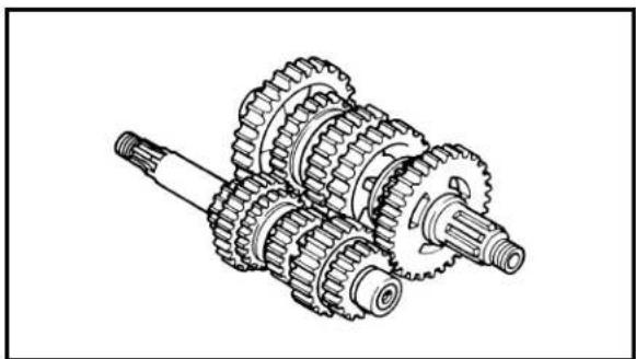
natural_image
Technical line drawing of a mechanical gear assembly (no text or symbols)- Check:
- Gears movement
Unsmooth movement → Repair or replace.
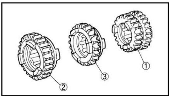
text_image
Technical diagram of three mechanical gear assemblies with numbered labels pointing to different components.
text_image
① ③ ② ④
text_image
Exploded view diagram of a mechanical assembly with numbered parts for identificationEC4H4300
Shift fork groove
1. Measure:
- 3rd/4th pinion gear ①
- 5th wheel gear ②
- 6th wheel gear ③
- Shift fork groove ⓐ
Out of specification → Replace.
| Shift fork groove ⓐ: | |
| Standard | |
| 5.05~5.18 mm 5.35 mm(0.199~0.204 in) (0.211 in) | |
EC4H4400
Thrust clearance
1. Check:
• After assembling the transmission, check whether the idle gear turns smoothly without a thrust.
If the thrust clearance is too large or the idle gear moves with difficulty → Replace the shim ①, ② and ③.
Choose the shims by the following chart.
| Part name | Size (thickness) | Part number |
| Shim 1 STD t=1.0 mm 9020(0.039 in)t=0.9 mm 9020(0.035 in) | 01-253K01-256E6 | |
| Shim 2 STD t=1.0 mm 9020(0.039 in)t=0.9 mm 9020(0.035 in) | 01-202761-206E5 | |
| Shim 3 STD t=0.7 mm 5F7-(0.028 in)t=0.5 mm 9020(0.020 in) | -17136-009-22082 |
NOTE:
It is necessary to adjust the thrust clearance when the transmission gear, axle, washer, circlip, bearing or crankcase is replaced.
EC4H4501
Dog clearance
NOTE:
- It is necessary to adjust the dog clearance when the transmission gear, axle, washer, circlip, bearing or crankcase is replaced.
- If there is any shifting trouble, it is necessary to check the shift fork, shift cam, shift lever and gears. But if there are in good condition, the dog clearance should be inspected.
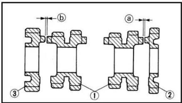
text_image
① ② ③ ① ② a b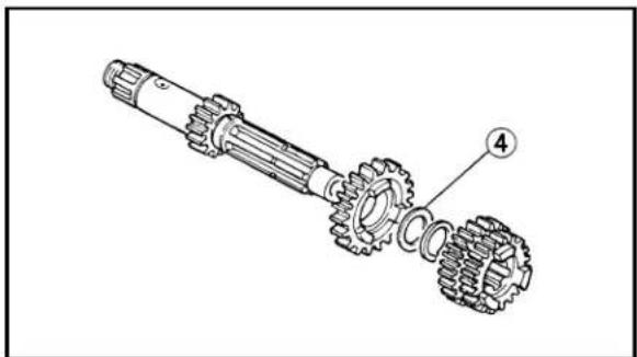
natural_image
Technical line drawing of a mechanical gear assembly with labeled component (no text or symbols present)
text_image
Technical diagram showing mechanical assembly with labeled parts and dimensional annotations- Install the transmission, shift cam and shift fork into the transmission housing.
- Position the transmission is neutral.
- Pull the main axle toward the clutch side.
- Bring the 3rd/4th pinion gear ① into light contact with the 6th pinion gear ② to the extent that they are not engaged, and measure the clearance a between 3rd/4th pinion gear and 6th pinion gear. Bring the 3rd/4th pinion gear into light contact with the 5th pinion gear ③ to the extent that they are not engaged and measure the clearance b between 3rd/4th pinion gear and 5th pinion gear.

Dog clearance ⓐ, Ⓑ: 0.5 mm (0.020 in) or more
Out of specification or clearance ① and ⑥ are not equal → Replace the shim ④. Choose the shim by the following chart.
| Part name | Size (thickness) | Part number |
| Shim 4 STD t=1.0 mm 9020(0.039 in)t=0.9 mm 9020(0.035 in) | 1-253K01-256E6 |
EC4H4600
Bearing
- Inspect:
- Bearing ① Rotate inner race with a finger. Rough spot/Seizure → Replace.
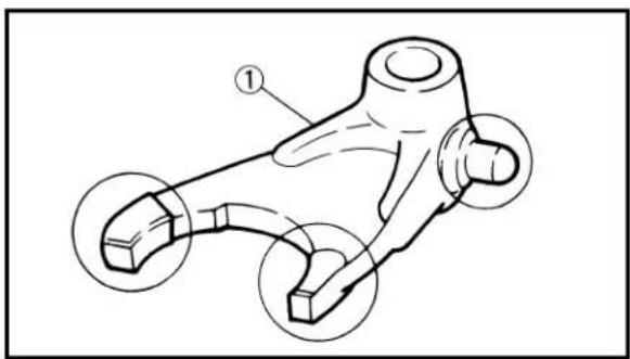
text_image
Technical diagram of a mechanical component with numbered callouts indicating parts of the body and features.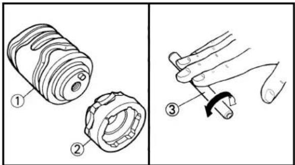
text_image
Technical diagram showing three labeled parts of a mechanical device, including a cylindrical component, a gear-like part, and a hand holding a cable.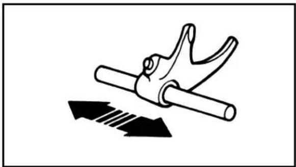
natural_image
Diagram of a hand gripping a cylindrical object with two curved arms, with an arrow indicating direction (no text or symbols)
text_image
Technical diagram of a mechanical assembly with labeled parts and a G tag indicatorEC4H4801
Shift fork, shift cam and segment
- Inspect:
- Shift fork ①
Wear/Damage/Scratches → Replace.
-
Inspect:
-
Shift cam ①
- Segment ②
- Guide bar ③
Bend/Wear/Damage → Replace.
- Check:
- Shift fork movement
On its guide bar.
Unsmooth operation → Replace shift fork and/or guide bar.
NOTE:
For a malfunctioning shift fork, replace not only the shift fork itself but the two gears each adjacent to the shift fork.
EC4H5000
ASSEMBLY AND INSTALLATION
EC4H5112
Shift cam
- Install:
- Shift cam ①
NOTE:
Apply the transmission oil on the shift cam bearing.
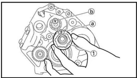
text_image
Technical diagram of a mechanical gear assembly with labeled parts (a, b, 1) and hand tool interacting with the gear.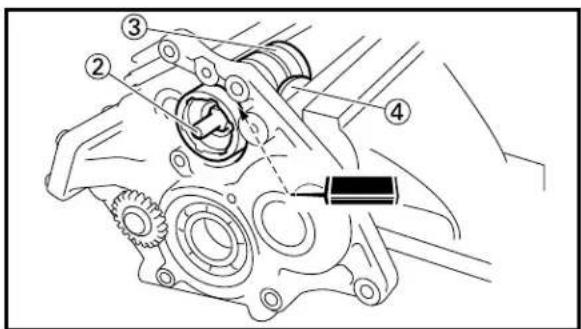
text_image
Technical diagram of a mechanical assembly with numbered components and directional arrows indicating motion or force.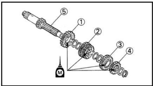
text_image
Technical diagram of a mechanical assembly with numbered components and a labeled component M
text_image
Technical diagram of a mechanical assembly with numbered components and labeled parts M2. Install:
- Segment ①
- Bolt (segment) ②

23 Nm (2.3 m·kg, 17 ft·lb)
NOTE:
- When installing the segment onto the shift cam, align the punch mark ⓐ with the dowel pin ⓑ.
- Clamp the shift cam ③ securely in a vise, using soft protecting material ④ to tighten the bolt (segment).
EC4H5232
Transmission
-
Install:
-
6th pinion gear (22T) ①
• 3rd/4th pinion gear (23T/25T) ② - 5th pinion gear (27T) ③
- 2nd pinion gear (21T) ④
To main axle ⑤.
NOTE:
Apply the molybdenum disulfide oil on the gears inner circumference.
2. Install:
- 2nd wheel gear (31T) ①
- 5th wheel gear (26T) ②
- 3rd wheel gear (29T) ③
• 4th wheel gear (27T) ④ - 6th wheel gear (20T) ⑤
- 1st wheel gear (34T) ⑥
To drive axle ⑦.
NOTE:
Apply the molybdenum disulfide oil on the gears inner circumference.

text_image
Main axle 6th pinion gear Plain washer 3rd/4th pinion gear 2nd pinion gear 5th pinion gear Circlip Plain washer Bearing Drive axle Circlip Plain washer 1st wheel gear 6th wheel gear 4th wheel gear Washer Circlip Plain washer 2nd wheel gear 5th wheel gear Circlip 3rd wheel gear
text_image
New ① ② ③ a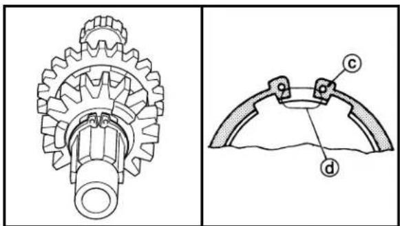
natural_image
Technical line drawing of a gear assembly (left) and a mechanical component with labeled parts (right), no text or symbols present.3. Install:
- Plain washer ①
- Circlip ② New
NOTE:
- Be sure the circlip sharp-edged corner (a) is positioned opposite to the plain washer and gear (b).
- Be sure the circlip end Ⓐ is positioned at axle spline groove ⓐ.
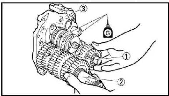
text_image
Technical diagram of a mechanical assembly with numbered components and labeled parts
text_image
Technical diagram of a mechanical gear assembly with numbered components for identification
text_image
Technical diagram of a mechanical assembly with labeled parts and a G tag, likely illustrating a gear or transmission mechanism.
natural_image
Mechanical assembly diagram showing hands operating a gear mechanism (no text or labels)
text_image
① ② ③ New B4. Install:
- Main axle ①
- Drive axle ②
NOTE:
- Apply the transmission oil on the main axle and drive axle bearings.
• Install the main axle together with the drive axle into the transmission housing ③.
5. Install:
- Shift fork 1 ①
- Shift fork 2 ②
- Shift fork 3 ③
NOTE:
- Mesh the shift fork #1 with the 5th wheel gear ④ and #3 with the 6th gear ⑥ on the drive axle.
- Mesh the shift fork #2 with the 3rd/4th pinion gear ⑤ on the main axle.
6. Install:
• Guide bar 1 (short) ①
- Guide bar 2 (long) ②
NOTE:
- Apply the transmission oil on the guide bars.
- Be sure the short bar is inserted into the shift fork #2 and the long one into #1 and #3.
7. Check:
- Shift operation
• Transmission operation
Unsmooth operation → Repair.
8. Install:
- Thrust plate ①
- Spacer 1 ②
- O-ring ③ New
NOTE:
Apply the lithium soap base grease on the O-ring.
EC4J0000
OIL PUMP

text_image
New 8 Nm (0.8 m·kg, 5.8 ft·lb) 7 Nm (0.7 m·kg, 5.1 ft·lb)Extend of removal: ① Oil pump removal and disassembly
| Extend of removal Order Part name Q'ty Remarks | |||
| Preparation for Transmission removal Shift shaft and Stopper housing leverTransmission and shift fork | Refer to “SHIFT SHAFT” section.Refer to “TRANSMISSION, SHIFT CAM AND SHIFT FORK” section. | ||
| 1 Strainer 12 Oil pump cover 13 Outer rotor 14 Inner rotor 15 Dowel pin 16 Plain washer 1[D=ø15 mm (0.59 in)]7 Plain washer 1[D=ø22 mm (0.87 in)]8 Oil pump gear shaft 19 Oil delivery pipe 1 | |||
text_image
Technical diagram of a mechanical assembly with numbered parts labeled ① and ②
natural_image
Line drawing of a hand using a tool to adjust a component with a grid pattern (no text or symbols)
text_image
Technical diagram of a mechanical gear assembly with labeled component 1
text_image
Technical diagram of a mechanical linkage or suspension system with labeled components and connection points
text_image
① New ② New ① BEC4J4000
INSPECTION
EC4J4100
Oil pump
- Measure:
- Tip clearance
Measure the clearance between the inner rotor ① and outer rotor ②.
Out of limit → Replace the inner rotor and outer rotor as a set.

Tip clearance limit: 0.15 mm (0.0059 in)
EC4E4310
Strainer
- Clean:
- Strainer ①
Use compressed air.
NOTE:
- Clean the strainer every 500 km (300 miles).
- If a lot of metallic dust in noticed, disassemble the engine and check.
EC4J4200
Oil pump gear shaft
- Inspect:
- Oil pump gear shaft ①
Wear/Damage → Replace.
EC4H4100
Oil delivery pipe
-
Inspect:
-
Oil delivery pipe ①
- O-ring ②
Damage → Replace.
- Oil orifice ⓐ
Clogged → Blow.
EC4J5000
ASSEMBLY AND INSTALLATION
EC4J5102
Oil pump
- Install:
- O-ring ① New
To oil delivery pipe ②.
NOTE:
Apply the lithium soap base grease on the O-rings.

text_image
Technical diagram of a mechanical gear assembly with labeled parts 1, 2, and a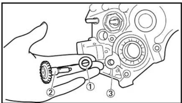
text_image
Technical diagram of a mechanical assembly with numbered parts for identification
text_image
Technical diagram showing mechanical assembly steps with numbered components and labeled parts (a, b, c, d, e, f)2. Install:
- Oil delivery pipe ①
NOTE:
When installing the oil delivery pipe, fit the projection of the oil delivery pipe into the hole on the crankcase.
3. Install:
- Plain washer [D=ø22 mm (0.87 in)] ①
- Oil pump gear shaft ②
To transmission housing ③.
4. Install:
- Plain washer [D=ø15 mm (0.87 in)] ①
- Dowel pin ②
- Inner rotor ③
- Outer rotor ④
To oil pump gear shaft ⑤.
NOTE:
- Apply the transmission oil on the inner rotor and outer rotor.
• Make sure the dowel pin fits into the groove (a) in the inner rotor. - When installing the outer rotor, make sure the punch mark ⓑ on the outer rotor face the transmission housing side.

text_image
Technical diagram of a mechanical assembly with numbered components and labeled parts5. Install:
- Dowel pin ①
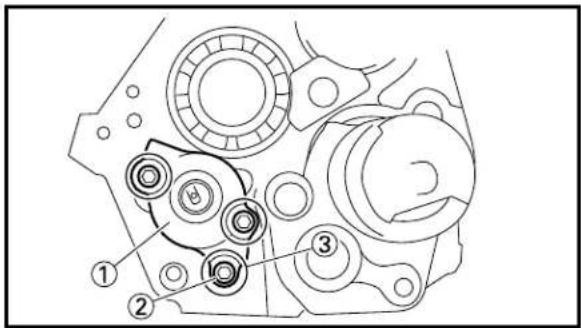
text_image
Technical diagram of a mechanical assembly with numbered components labeled 1, 2, and 3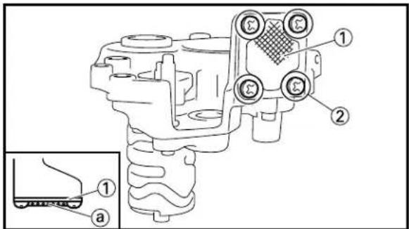
text_image
Technical diagram of a mechanical component with labeled parts and an inset showing a close-up detail of a connector or assembly.6. Install:
- Oil pump cover ①
- Plain washer ②
- Bolt (oil pump cover) ③
8 Nm (0.8 m·kg, 5.8 ft·lb)
NOTE:
While turning the oil pump gear shaft, install the oil pump cover.
7. Install:
- Strainer ①
- Screw (strainer) ②
7 Nm (0.7 m·kg, 5.1 ft·lb)
NOTE:
Strainer is installed with the mesh ⓐ facing outward.
EC4L0000
CDI MAGNETO


text_image
7 Nm (0.7 m·kg, 5.1 ft·lb) 53 Nm (5.3 m·kg, 38 ft·lb)Extend of removal: ① CDI magneto removal
| Extend of removal Order Part name Q'ty Remarks | ||||
| Preparation for Cowling and fuel tank Refer to “COWLING, INDUCTION removal GUIDE, SEAT AND FUEL TANK”Disconnect the CDI magneto lead. | section. | |||
| 1 Nut (rotor) 1 Use special tool.2 Rotor 1 Refer to “REMOVAL POINTS”.3 Stator 14 Woodruff key | 1 | |||
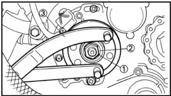
text_image
Technical diagram of a mechanical assembly with numbered components and labeled parts
text_image
Technical diagram showing mechanical assembly with numbered components and tool path
natural_image
Technical line drawing of a mechanical component with two views: top shows internal gear assembly, bottom shows close-up of cylindrical housing (no text or symbols)
text_image
Technical diagram of a mechanical assembly with labeled components 1 and 2, showing gear and housing connections.
text_image
Technical diagram of a mechanical assembly with numbered components, likely illustrating gear or gear mechanism.EC4L3000
REMOVAL POINTS
EC4L3102
Rotor
-
Remove:
-
Nut (rotor) ①
- Plain washer ②
Use the rotor holding tool ③.

Rotor holding tool: YU-1235/90890-01235
- Remove:
- Rotor ①
Use the flywheel puller ②.

Flywheel puller: YM-1189/90890-01189
NOTE:
When installing the flywheel puller, turn it counterclockwise.
EC4L4000
INSPECTION
EC4L4101
CDI magneto
-
Inspect:
-
Rotor inner surface ⓐ
- Stator outer surface ⑥
Damage → Inspect the crankshaft runout and crankshaft bearing.
If necessary, replace CDI magneto and/or stator.
EC4L4200
Woodruff key
- Inspect:
- Woodruff key ①
Damage → Replace.
EC4L5000
ASSEMBLY AND INSTALLATIO
EC4L5191
CDI magneto
-
Install:
-
Stator ①
- Screw (stator) ②
NOTE:
Temporarily tighten the screw (stator) at this point.
CDI MAGNETO
ENG


text_image
Technical diagram of mechanical assembly with labeled parts and cross-sectional view2. Install:
- Woodruff key ①
- Rotor ②
NOTE:
- Clean the tapered portions of the crankshaft and rotor.
- When installing the woodruff key, make sure that its flat surface ① is in parallel with the crankshaft center line ② .
- When installing the rotor, align the keyway © of the rotor with the woodruff key.

text_image
Technical diagram of a mechanical assembly with numbered components, likely illustrating gear or cam mechanism.3. Install:
- Plain washer ①
- Nut (rotor) ② 53 Nm (5.3 m·kg, 38 ft·lb)
Use the rotor holding tool ③.

Rotor holding tool: YU-1235/90890-01235
4. Adjust:
- Ignition timing

Ignition timing: 2.4 mm (0.094 in)
Refer to "IGNITION TIMING CHECK" section in the CHAPTER 3.
natural_image
Technical line drawing of a mechanical assembly with gears and levers (no text or symbols)5. Connect:
- CDI magneto lead ① Refer to “CABLE ROUTING DIAGRAM” section in the CHAPTER 2.
EC4M0000
ENGINE REMOVAL
text_image
30 Nm (3.0 m•kg, 22 ft•lb) 8 Nm (0.8 m•kg, 5.8 ft•lb) 11 Nm (1.1 m•kg, 8.0 ft•lb) 23 Nm (2.3 m•kg, 17 ft•lb) 30 Nm (3.0 m•kg, 22 ft•lb) 11 Nm (1.1 m•kg, 8.0 ft•lb) 23 Nm (2.3 m•kg, 17 ft•lb)| Extend of removal Order Part | name Q'ty Remarks | |||
| Preparation for Hold the machine removal the suitable stand. | ENGINE REMOVAL | ⚠WARNINGSupport the machine securely so there is no danger of it falling over. | ||
| Cowl ing and fuel tank Refer to “COWLING, INDUCTIONGUIDE, SEAT AND FUEL TANK” section. | ||||
| Carburetor and carburetor box Refer to “CARBURETOR AND REED VALVE” section. | ||||
| Exhaust pipe Refer to “EXHAUST PIPE AND SILENCER” section. | ||||
| Clutch cable Disconnect at engine side. | ||||
| Radiator hose 2 | ||||
| Radiator hose 3, 4 | ||||
| Drive sprocket | ||||
| Shift arm | ||||
| Spark plug cap | ||||
| YPVS cable | ||||
| Disconnect the CDI magneto lead. | ||||

text_image
30 Nm (3.0 m•kg, 22 ft•lb) 8 Nm (0.8 m•kg, 5.8 ft•lb) 11 Nm (1.1 m•kg, 8.0 ft•lb) 23 Nm (2.3 m•kg, 17 ft•lb) 30 Nm (3.0 m•kg, 22 ft•lb) 11 Nm (1.1 m•kg, 8.0 ft•lb) 23 Nm (2.3 m•kg, 17 ft•lb)Extend of removal: ① Engine removal
| Extend of removal Order Part name Q'ty Remarks | ||||
| 1 | Pinch bolt (engine mounting collar) | 2 Only loosening. | ||
| 2 Nut (engine mounting bolt) 4 | ||||
| 3 Engine mounting adjust bolt 2 | ||||
| 4 Engine mounting bolt 4 Refer to “RE | MOVAL | POINTS.” | ||
| 5 Engine 1 | ||||
| 6 Engine bracket 2 | ||||
text_image
Technical diagram of a mechanical component with numbered parts labeled 1, 2, and a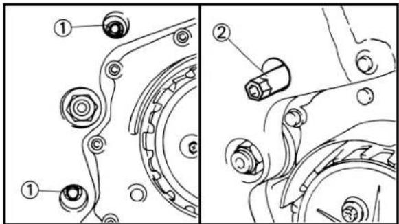
text_image
Technical diagram showing mechanical assembly with numbered components, likely illustrating a gear or linkage mechanism.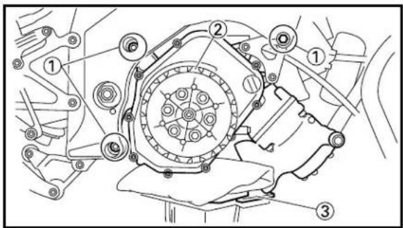
text_image
Technical diagram of a mechanical assembly with numbered components, likely for assembly or maintenance instructions.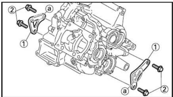
text_image
Technical diagram of an internal combustion engine assembly with labeled parts and numbered annotationsEC4M6000
HANDLING NOTE
When the frame alone is stored, insert the engine mounting collars ① into the brackets and tighten them with the pinch bolts ② to 6 Nm (0.6 m·kg, 4.3 ft·lb) in order to prevent the brackets ③ from damage.
EC4M3000
REMOVAL POINTS
EC4M3331
Engine removal
- Loosen:
- Engine mounting adjust bolt ①
NOTE:
Use the adjust bolt wrench ② to loosen the engine mounting adjust bolt.
-
Remove:
-
Engine mounting bolt ①
- Engine ②
NOTE:
- Before removing the engine, make sure that the couplers, hoses and cables are disconnected.
- Remove the engine by lowering it with a jack ③.
EC4M5000
ASSEMBLY AND INSTALLATION
EC4M5190
Engine installation
-
Install:
-
Engine bracket ①
- Bolt (engine bracket) ②
NOTE:
- Install the engine brackets with their "OUTSIDE" marks @ facing outward.
- Tighten the bolts (engine brackets) to 23 Nm (2.3 m·kg, 17 ft·lb), then loosen them by 1/4 turn, for temporary fitting.

text_image
Technical diagram of a mechanical assembly with numbered components, likely illustrating a gear or cam mechanism.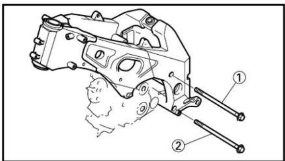
text_image
Technical diagram of a mechanical assembly with numbered parts labeled ① and ②
text_image
Technical diagram showing mechanical assembly with numbered components, likely illustrating a gear or linkage mechanism.
text_image
Technical diagram of a mechanical assembly with numbered components, likely for assembly or maintenance instructions.2. Install:
- Engine ①
NOTE:
Install the engine by raising it into the frame with a jack ②.
3. Install:
• Engine mounting bolt (upper) ①
- Engine mounting bolt (lower) ②
4. Tighten:
• Engine mounting adjust bolt ①
8 Nm (0.8 m·kg, 5.8 ft·lb)
NOTE:
- Use the adjust bolt wrench ② to tighten the engine mounting adjust bolts.
- Tighten the adjust bolts to specified torque alternately two times.
5. Install:
- Nut (engine mounting bolt) (upper) ①
30 Nm (3.0 m·kg, 22 ft·lb) - Nut (engine mounting bolt) (lower) ②
30 Nm (3.0 m·kg, 22 ft·lb)
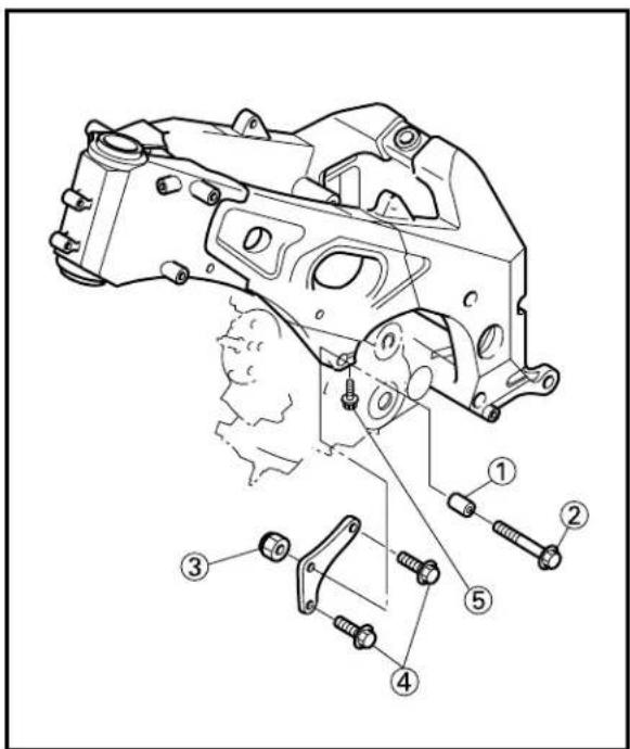
text_image
Technical diagram of a mechanical assembly with numbered parts for identification
text_image
Technical diagram of a mechanical assembly with numbered parts for identification6. Install:
• Engine mounting collar (left) ①
• Engine mounting bolt (left) ②
• Engine mounting nut (left) ③
30 Nm (3.0 m·kg, 22 ft·lb)
7. Tighten:
- Bolt (engine bracket) (left) ④
23 Nm (2.3 m·kg, 17 ft·lb)
8. Tighten:
- Pinch bolt (engine mounting collar) (left) ⑤
11 Nm (1.1 m·kg, 8.0 ft·lb)
9. Install:
• Engine mounting collar (right) ①
• Engine mounting bolt (right) ②
• Engine mounting nut (right) ③
30 Nm (3.0 m·kg, 22 ft·lb)
10.Tighten:
- Bolt (engine bracket) (right) ④
23 Nm (2.3 m·kg, 17 ft·lb)
11.Tighten:
- Pinch bolt (engine mounting collar) (right) ⑤
11 Nm (1.1 m·kg, 8.0 ft·lb)
EC4N0000
CRANKCASE AND CRANKSHAFT
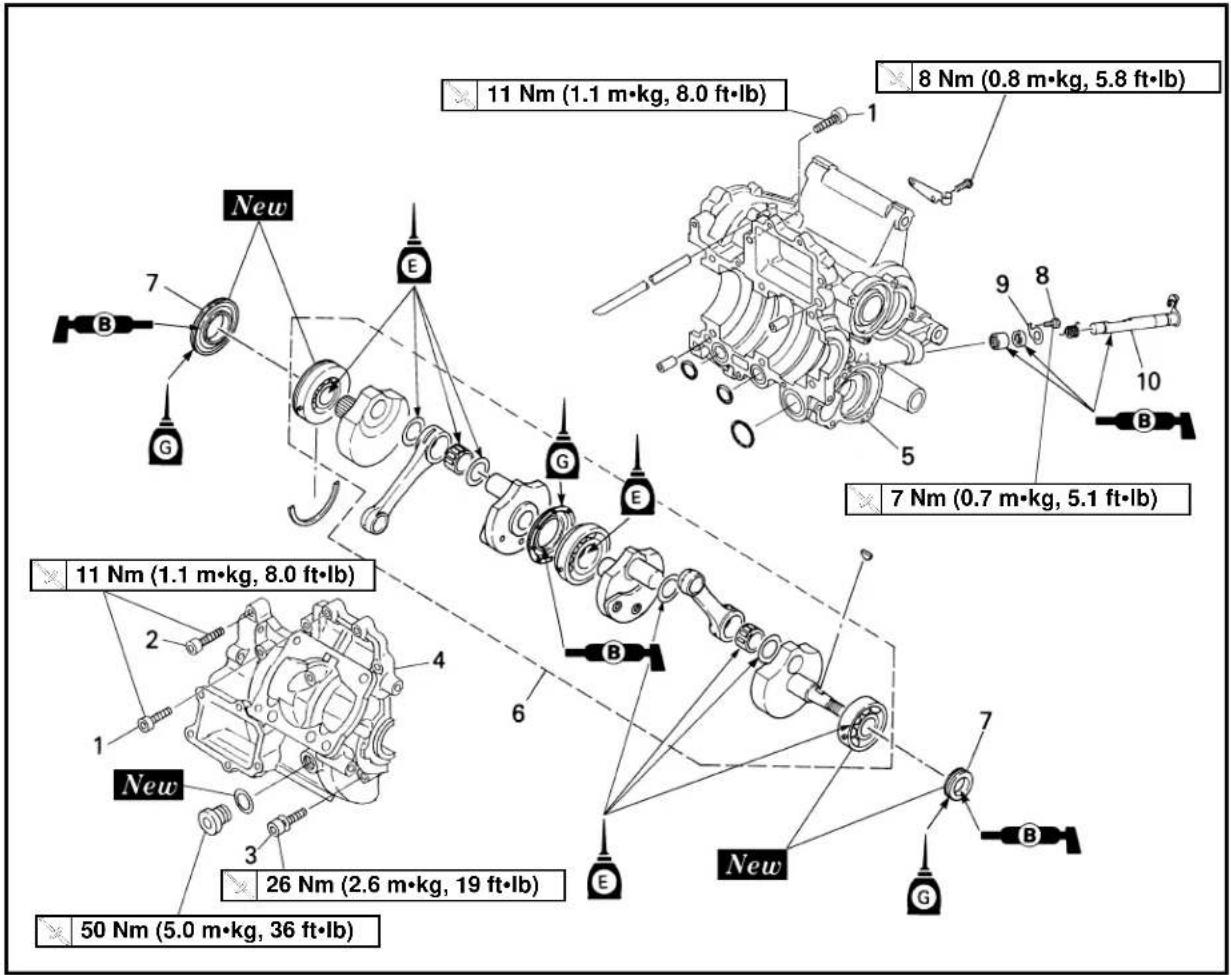
text_image
11 Nm (1.1 m•kg, 8.0 ft•lb) 8 Nm (0.8 m•kg, 5.8 ft•lb) 7 Nm (0.7 m•kg, 5.1 ft•lb) 26 Nm (2.6 m•kg, 19 ft•lb) 50 Nm (5.0 m•kg, 36 ft•lb)| Extend of removal Order Part | name Q'ty Remarks | |||
| Preparation for Engine removal section. | Refer to | CRANKCASE AND CRANK SHAFT REMOVAL“ENGINE REMOVAL”Reed valve Refer to “CARBURETOR AND REED VALVE” section.Piston Refer to “CYLINDER HEAD, CYLIN-DER AND PISTON” section.Primary drive gear Refer to “PRIMARY DRIVEN GEAR, PRIMARY DRIVE GEAR AND BALANCER SHAFT” section.Rotor and stator Refer to “CDI MAGNETO” section.Engine bracket | ||
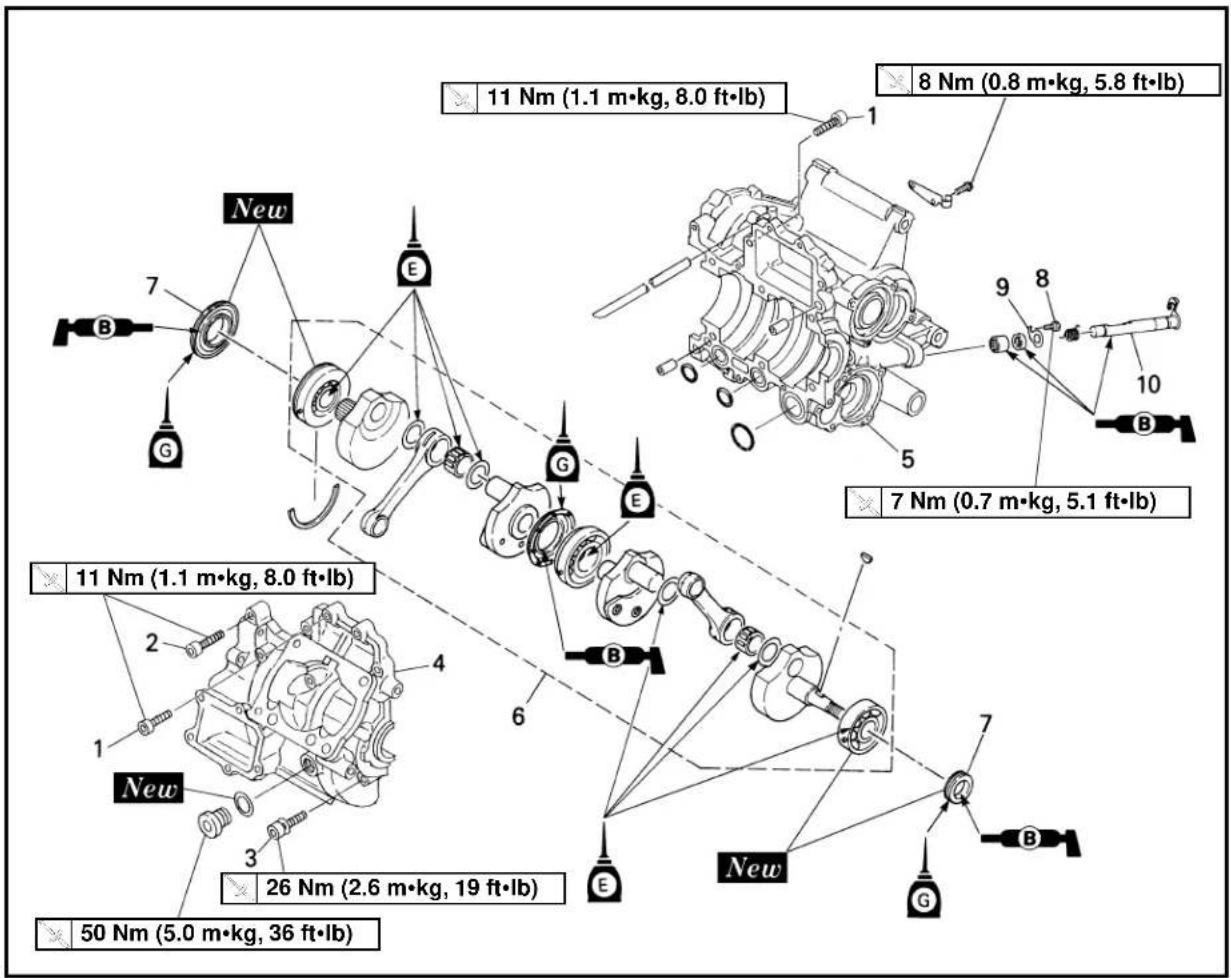
text_image
11 Nm (1.1 m•kg, 8.0 ft•lb) 8 Nm (0.8 m•kg, 5.8 ft•lb) 7 Nm (0.7 m•kg, 5.1 ft•lb) 26 Nm (2.6 m•kg, 19 ft•lb) 50 Nm (5.0 m•kg, 36 ft•lb)Extend of removal: ① Crankcase separation ② Crankshaft removal
③ Oil seal removal ④ Push lever axle removal
| Extend of removal Order Part name Q'ty Remarks | ||||
| 1 Bolt [crankcase (M6)] 6[ =30 mm (1.18 in)]2 Bolt [crankcase (M6)] 3[ =35 mm (1.38 in)]3 Bolt [crankcase (M8)] 6[ =45 mm (1.77 in)]4 Crankcase (upper) 15 Crankcase (lower) 16 Crankshaft 17 Oil seal (crankshaft) 28 Bolt (seat plate) 19 Seat plate 110 Push lever axle 1 | Refer to “REMOVAL POINTS”. | |||
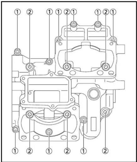
text_image
Technical diagram of a mechanical assembly with numbered components for identification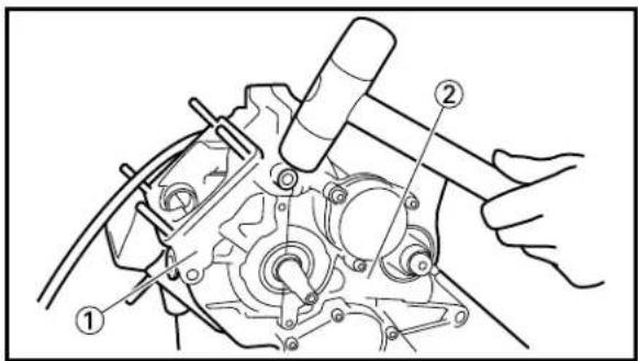
text_image
Technical diagram of a mechanical assembly with numbered components, likely for repair or maintenance instructions.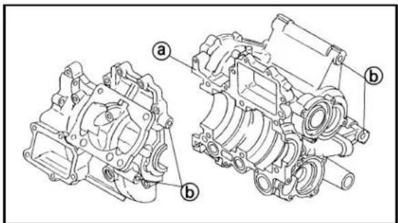
text_image
Technical diagram of an engine cylinder assembly with labeled parts a and b
text_image
Technical diagram showing mechanical assembly with labeled parts and cross-sectional viewsEC4N3000
REMOVAL POINTS
EC4N3230
Crankcase
-
Remove:
-
Bolt [crankcase (M6)] ①
• Bolt [crankcase (M8)] ②
NOTE:
• The M6 size bolts should be removed first.
- Loosen the bolts from the outer sides inward.
- Remove:
- Crankcase (upper) ①
From crankcase (lower) ②.
CAUTION:
Use soft hammer to tap on the case half. Tap only on reinforced portions of case. Do not tap on gasket mating surface. Work slowly and carefully. If the cases do not separate, check for a remaining case screw or fitting. Do not force.
EC4N4000
INSPECTION
EC4N4112
Crankcase
-
Inspect:
-
Contacting surface ⓐ Scratches → Replace crankcase assembly.
- Engine mounting boss ⓑ, crankcase Cracks/Damage → Replace crankcase assembly.
EC4N4214
Crankshaft
- Inspect:
- Bearing ①
Rotate outer race with a finger.
Rough spot/Seizure → Replace crankshaft assembly.
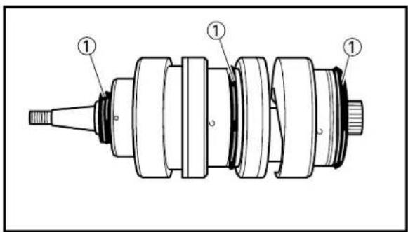
text_image
Technical diagram of a mechanical assembly with numbered components labeled ①
text_image
a b a a b
text_image
c d d c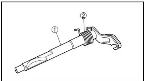
text_image
Technical diagram of a mechanical tool with labeled parts ① and ②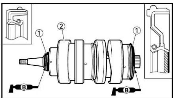
text_image
Technical diagram of a mechanical assembly with labeled parts and cross-sectional views2. Inspect:
- Oil seal ① Wear/Damage → Replace.
3. Measure:
- Runout limit ⓐ
- Small end free play limit ⓑ
- Connecting rod big end side clearance ©
- Crank width (crank pin side) ⓓ
Out of specification → Replace.
Use the dial gauge and thickness gauge.

Dial gauge: YU-3097/90890-01252
| Standard | ||
| Runout 0.0 limit (0.0012 in) (0.0020 in) | 3 mm 0.05 mm | |
| Small end free play (0.031~0.039 in) (0.08 in) | 0.8~1.0 mm 2.0 mm | |
| Side 0.45~ clearance | 0.95 mm (0.018~0.037 in) | - |
| Crank width (1.968~1.969 in) | 49.975~50.025 mm | - |
EC4A4200
Push lever axle
1. Inspect:
- Push lever axle ①
Wear/Damage → Replace. - Torsion spring ②
Broken/Damage → Replace.
EC4N5000
ASSEMBLY AND INSTALLATION
EC4N5291
Crankshaft
1. Install:
- Oil seal ①
To crankshaft ②.
NOTE:
Apply the lithium soap base grease on the oil seal lip.
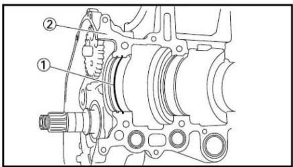
text_image
Technical diagram of a mechanical assembly with labeled parts ① and ②
text_image
Technical diagram of a mechanical assembly with labeled components and parts2. Install:
- Circlip ①
To crankcase (lower) ②.
3. Install:
- Crankshaft ①
To crankcase (lower) ②.
NOTE:
- When installing the crankshaft into the crankcase (lower), apply the transmission oil on the oil seal ③ outer circumference.
- Align the bearing knock pin with the pin slot ① in the crankcase (lower) and the projection of oil seal with the groove ② in the crankcase (lower).
• After installing the crankshaft, push the oil seal to the crankcase (lower).

text_image
Technical diagram of a mechanical assembly with numbered components for identification
text_image
Technical diagram of a mechanical component with labeled parts, showing internal structure and assembly details.4. Install:
- Dowel pin ①
- O-ring ②
To crankcase (lower) ③.
5. Apply:
- Sealant
On the crankcase (upper) ①.

Quick gasket®:
ACC-YAMAB-ON-D4
YAMAHA Bond No.4
90890-05143
NOTE:
Clean the contacting surface of crankcase (upper and lower) before applying the sealant.
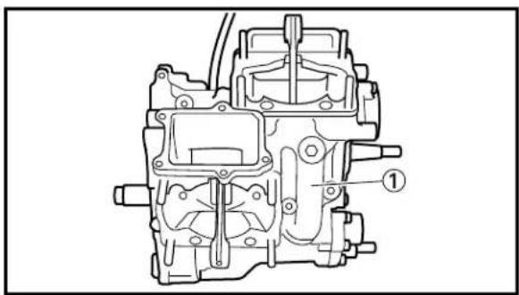
natural_image
Technical line drawing of a mechanical assembly (no text or symbols)
text_image
Technical diagram of a mechanical assembly with numbered components for identification- Install:
- Crankcase (upper) ①
To crankcase (lower).
NOTE:
After installation, tap the crankcase (upper) with a soft hammar to settle it.
- Tighten:
- Bolt [crankcase (M8)] ①\~⑥
- Bolt [crankcase (M6)] ⑦\~⑮
CAUTION:
The M6 bolt comes in two lengths. Use the correct one for installation.
=30 mm (1.18 in) (green) ⑦ ⑩ ⑪ ⑬ ⑭ ⑮
Mark ※:ℓ=35 mm (1.38 in) (silver) ⑧ ⑨ ⑫
NOTE:
Tighten all bolts in 2 steps as follows and be sure to tighten in numbered order as shown.
-First: ①\~⑥ (M8) 11 Nm (1.1 m·kg, 8.0 ft·lb)
⑦\~⑮ (M6) 6 Nm (0.6 m·kg, 4.3 ft·lb)
•Final: ①\~⑥ (M8) 26 Nm (2.6 m•kg, 19 ft•lb)
⑦\~⑮ (M6) 11 Nm (1.1 m·kg, 8.0 ft·lb)
- Remove:
- Sealant
Forced out on the crankcase mating surface.
CAUTION:
If any sealant remains, especially where the stator is installed, it may cause the stator to be installed improperly, resulting in an electrical problem.
- Apply:
- Engine oil
To the crank pin, bearing and oil delivery hole.
10.Check:
- Crankshaft operation
Unsmooth operation → Repair.

text_image
Technical diagram showing mechanical assembly with numbered components and a labeled component B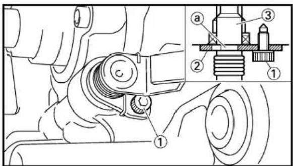
text_image
Technical diagram of a mechanical assembly with numbered components and an inset showing a bolted joint detail.EC4A5101
Push lever axle
-
Install:
-
Seat plate ①
- Torsion spring ②
- Push lever axle ③
NOTE:
Apply the lithium soap base grease on the push lever axle, oil seal lip and bearing.
- Install:
- Bolt (seat plate) ①
7 Nm (0.7 m·kg, 5.1 ft·lb)
NOTE:
Fit the seat plate ② in the groove a of the push lever axle ③ and tighten the bolt (seat plate).
EC500000
CHASSIS
EC590000
FRONT WHEEL AND REAR WHEEL
EC598000
FRONT WHEEL
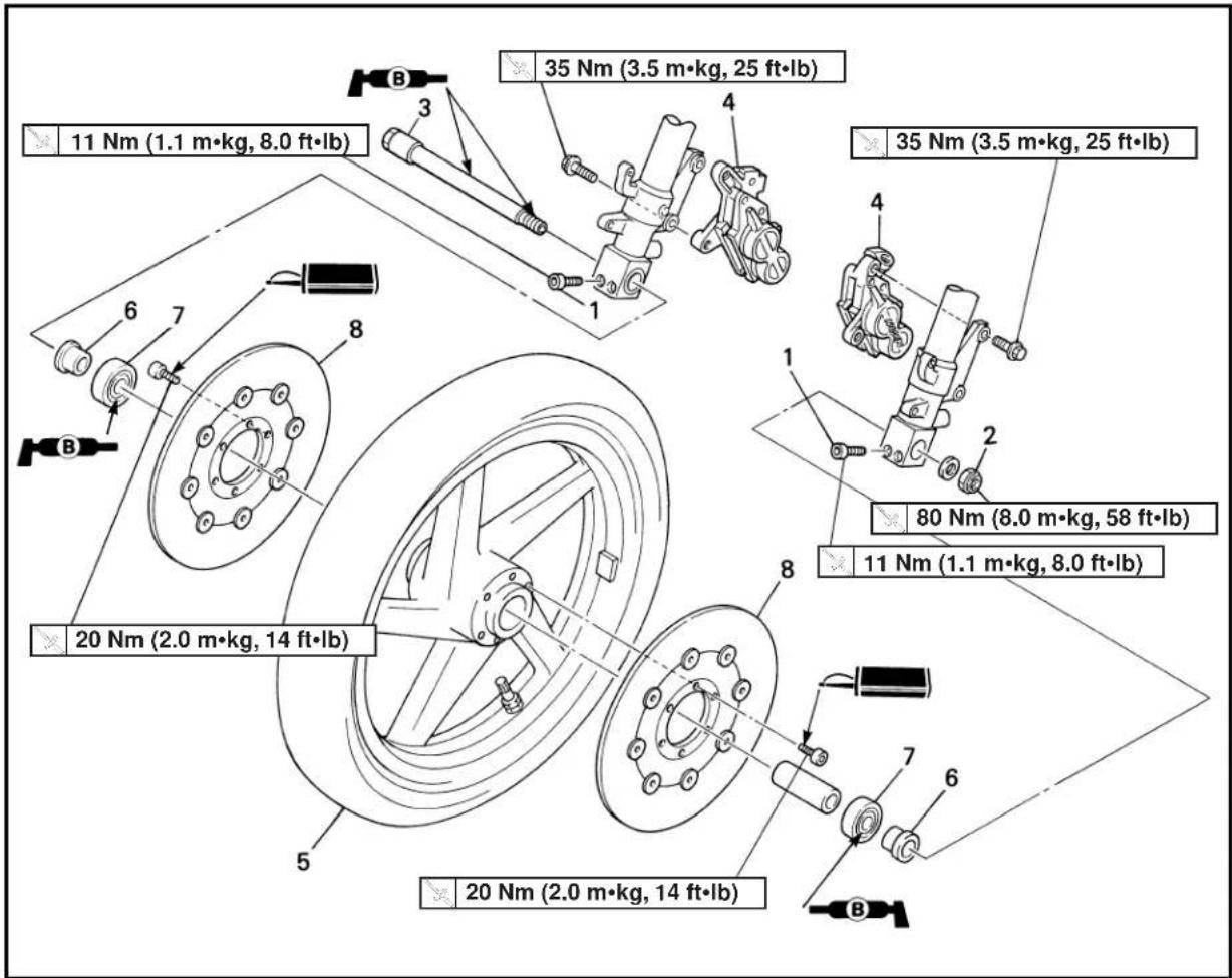
text_image
11 Nm (1.1 m•kg, 8.0 ft•lb) 20 Nm (2.0 m•kg, 14 ft•lb) 35 Nm (3.5 m•kg, 25 ft•lb) 35 Nm (3.5 m•kg, 25 ft•lb) 80 Nm (8.0 m•kg, 58 ft•lb) 11 Nm (1.1 m•kg, 8.0 ft•lb) 20 Nm (2.0 m•kg, 14 ft•lb)Extend of removal: ① Front wheel removal ② Wheel bearing removal
③ Brake disc removal
| Extend of removal Order Part name Q'ty Remarks | |||||
| Preparation for Hold the machine by placingremoval the suitable stand. | FRONT WHEEL REMOVAL | ⚠WARNINGSupport the machine securely so there is no danger of it falling over. | |||
 | 1 Bolt (axle holder)2 Nut (front wheel axle)3 Front wheel axle4 Caliper5 Front wheel6 Collar7 Bearing8 Brake disk | 4 Only loosening.2 Refer to “REMOVAL POINTS”.2 Refer to “REMOVAL POINTS”. | |||
EC598100
REAR WHEEL

text_image
80 Nm (8.0 m•kg, 58 ft•lb) 2 Nm (0.2 m•kg, 1.4 ft•lb) 23 Nm (2.3 m•kg, 17 ft•lb) 16 Nm (1.6 m•kg, 11 ft•lb) 32 Nm (3.2 m•kg, 23 ft•lb) 16 Nm (1.6 m•kg, 11 ft•lb) 2 Nm (0.2 m•kg, 1.4 ft•lb)Extend of removal: ① Rear wheel removal ② Wheel bearing removal
③ Brake disc removal
| Extend of removal Order Part name Q'ty Remarks | |||||
| Preparation for Hold the machine by placingremoval the suitable stand. | REAR WHEEL REMOVAL | ⚠WARNINGSupport the machine securely so there is no danger of it falling over. | |||
 | 1 Nut (rear wheel axle) 12 Rear wheel axle 13 Rear wheel 1 Refer to “REMOVAL POINTS”.4 Collar 15 Clutch hub 16 Shim 17 Driven sprocket 18 Sprocket damper 59 Collar 10 Bearing 11 Brake disc | Refer to “REMOVAL POINTS”.2 Refer to “REMOVAL POINTS”.1 | |||

text_image
Technical diagram showing mechanical assembly with labeled parts ① and ②, including hands and chains.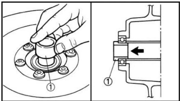
text_image
Technical diagram showing mechanical assembly with labeled parts and directional arrow indicating movement or force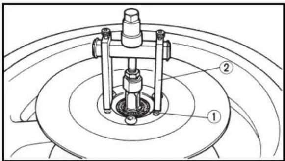
text_image
Technical diagram of a mechanical assembly with labeled parts 1 and 2, showing concentric circular components.
natural_image
Technical line drawing of a car wheel assembly with mounting bracket (no text or symbols)
natural_image
Technical line drawing of two mechanical bearing components with alignment arrows (no text or symbols)EC593000
REMOVAL POINTS
EC523101
Rear wheel
- Remove:
- Wheel ①
NOTE:
Push the wheel forward and remove the drive chain ②.
EC513300
Collar
- Remove:
- Collar ①
Knock out of wheel on inside.
NOTE:
Knock the collar out of the wheel gradually not to deform it.
EC513201
Wheel bearing (if necessary)
- Remove:
- Bearing ①
NOTE:
Remove the bearing using a general bearing puller ②.
EC594000
INSPECTION
EC514110
Wheel
- Measure:
- Wheel runout
Out of limit → Replace.

Wheel runout limit:
Radial: 1.0 mm (0.04 in)
Lateral: 0.5 mm (0.02 in)
- Inspect:
- Bearing
Rotate inner race with a finger.
Rough spot/Seizure → Replace.
NOTE:
Replace the bearings and wheel collar as a set.

text_image
Technical diagram showing a dial indicator measuring a mechanical setup with labeled component 1 and rotation arrowEC514200
Wheel axle
1. Measure:
- Wheel axle bends
Out of specification → Replace.
Use the dial gauge ①.

Wheel axle bending limit: 0.25 mm (0.010 in)
NOTE:
The bending value is shown by one half of the dial gauge reading.
WARNING
Do not attempt to straighten a bent axle.
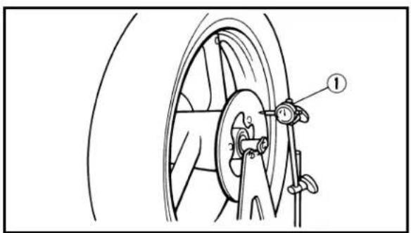
natural_image
Technical line drawing of a car steering wheel with a dial indicator (no text or symbols)
text_image
Technical diagram showing a mechanical assembly with labeled component ①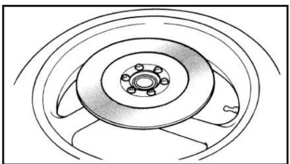
natural_image
Technical line drawing of a car wheel assembly with concentric rings and mounting holes (no text or symbols)EC594100
Brake disc
1. Measure:
- Brake disc deflection (only rear brake disc) Use the dial gauge ①. Out of specification → Inspect wheel runout. If wheel runout is in good condition, replace the brake disc.
| Disc deflection limit: | |
| Standard | |
| Rear | -0.15 mm (0.006 in) |
2. Measure:
- Brake disc thickness Use the micrometer ①. Out of limit → Replace.
| Disc wear limit: | ||
| Standard | ||
| Front | 5.0 mm (0.20 in) | 4.5 mm (0.18 in) |
| Rear | 4.0 mm (0.16 in) | 3.5 mm (0.14 in) |
3. Inspect:
- Brake disc surface Score marks/Damege → Replace.
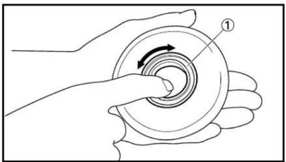
natural_image
Illustration of a hand holding a circular mechanical component with a rotating arrow indicating rotation (no text or symbols)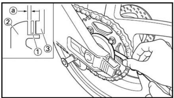
text_image
Technical diagram showing mechanical assembly with labeled parts and a magnified detail viewEC524100
Clutch hub
1. Inspect:
- Bearing ① Rotate inner race with a finger. Rough spot/Seizure → Replace.
EC594300
Clucth hub clearance
1. Inspect:
- Clucth hub clearance ⓐ Out of specification → Adjust by adding the supplied shim [0.3 mm (0.012 in)].

Clucth hub clearance: Zero\~0.3 mm (Zero\~0.012 in)
NOTE:
- When inspecting the clutch hub clearance, measure it as it is assembled to the body at specified torque. - Measurement may be made of the clearance either between the shim ① and clutch hub ② or between the shim and sprocket ③.
text_image
Technical diagram of a car wheel assembly with labeled parts and numbered annotationsEC595000
ASSEMBLY AND INSTALLATION
EC515172
Front wheel
1. Install:
- Bearing (right) ①
- Spacer ②
- Bearing (left) ③
NOTE:
- Apply the lithium soap base grease on the bearing when installing.
- Use a socket that matches the outside diameter of the race of the bearing.
- Right side of bearing shall be installed first.
CAUTION:
Do not strike the inner race of the bearing. Contact should be made only with the outer race.

text_image
Technical diagram of a mechanical or electrical component with numbered parts and labeled parts ①, ②, ③, ④, ⑤, ⑥.
text_image
Technical diagram showing a hand operating a mechanical component with labeled parts and a pointer indicating 'B'
text_image
Technical diagram showing a hand operating a mechanical component with numbered parts labeled ① and ②.
text_image
Technical diagram of a vehicle brake system with labeled components and motion indicators
text_image
Technical diagram showing a hand holding a mechanical component with numbered parts labeled ① and ②, and a tool labeled B pointing to the component.2. Install:
- Brake disc ①
- Bolt (brake disc) ②

NOTE:
Tighten the bolts in stage, using a crisscross pattern.
3. Install:
- Collar ①
NOTE:
If the collar is hard to install, apply the lithium soap base grease on the collar and press it in.
4. Install:
- Wheel ①
- Caliper ②
- Bolt (caliper)

NOTE:
Before installing the wheel axle, install the caliper.
5. Install:
- Wheel axle ①
NOTE:
- Apply the lithium soap base grease on the wheel axle.
- Insert the wheel axle from right side.
6. Install:
- Plain washer ①
- Nut (wheel axle) ②

NOTE:
Apply the lithium soap base grease on the wheel axle thread.

text_image
Technical diagram showing two mechanical components with labeled parts, including numbered annotations ① and ②.
text_image
Technical diagram of a car wheel assembly with labeled parts and directional arrows indicating components
text_image
Technical diagram of a mechanical component with numbered parts and directional arrows indicating motion or flow.
text_image
Technical diagram showing hands assembling a mechanical component with labeled parts ① and ⑧- Tighten:
- Bolt (axle holder) ①
11 Nm (1.1 m·kg, 8.0 ft·lb)
EC5251C0
Rear wheel
-
Install:
-
Fitting plate (right) ①
- Bearing (right) ②
- Spacer ③
- Fitting plate (left) ④
- Bearing (left) ⑤
NOTE:
- Apply the lithium soap base grease on the bearing when installing.
- Use a socket that matches the outside diameter of the race of the bearing.
- Right side of bearing shall be installed first.
CAUTION:
Do not strike the inner race of the bearing. Contact should be made only with the outer race.
-
Install:
-
Brake disc ①
- Bolt (brake disc) ②
23 Nm (2.3 m·kg, 17 ft·lb)
NOTE:
Tighten the bolts in stage, using a crisscross pattern.
- Install:
- Collar ①
NOTE:
If the collar is hard to install, apply the lithium soap base grease on the collar and press it in.
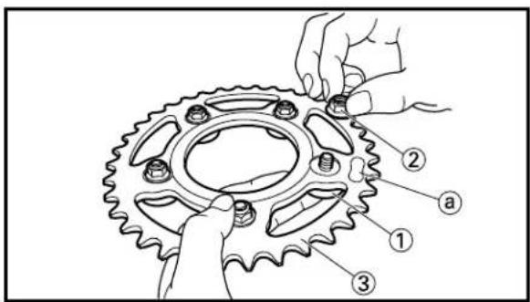
text_image
Technical diagram of a mechanical gear assembly with numbered parts labeled 1, 2, and 3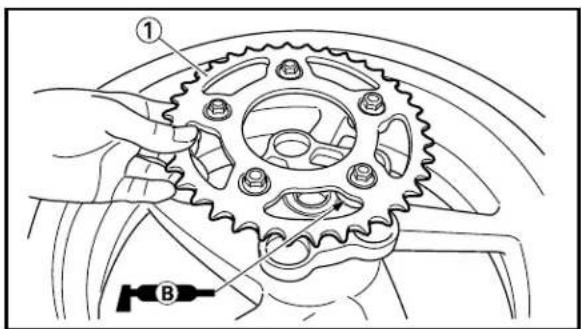
text_image
Technical diagram showing a gear assembly with labeled parts and a tool symbol for 'B'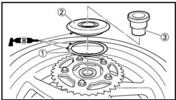
text_image
Technical diagram of a mechanical assembly with labeled parts and tool, showing gear and component layout.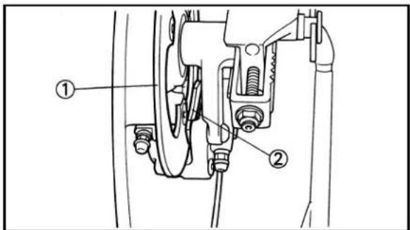
text_image
Technical diagram of a mechanical assembly with numbered components, likely for assembly or maintenance instructions.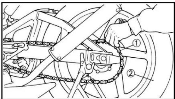
text_image
Technical diagram showing mechanical assembly with labeled parts, including chain links and numbered components-
Install:
-
Sprocket damper ①
- Nut (sprocket damper) ②
32 Nm (3.2 m·kg, 23 ft·lb)
To driven sprocket ③.
NOTE:
Make sure that the nut is on the side of the sprocket bearing the manufacturer's mark ⓐ.
- Install:
- Driven sprocket ①
To wheel.
NOTE:
Apply the lithium soap base grease on the sprocket damper.
-
Install:
-
Shim ①
- Clutch hub ②
- Collar ③
NOTE:
Apply the lithium soap base grease on the shim and clutch hub outer circumference.
- Install:
- Wheel
NOTE:
Install the brake disc ① between the brake pads ② correctly.
- Install:
- Drive chain ①
NOTE:
Push the wheel ② forward and install the drive chain.
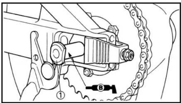
text_image
Technical diagram of a mechanical gear assembly with labeled components and motion indicators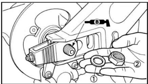
text_image
Technical diagram showing hands operating a mechanical component with numbered parts labeled ① and ②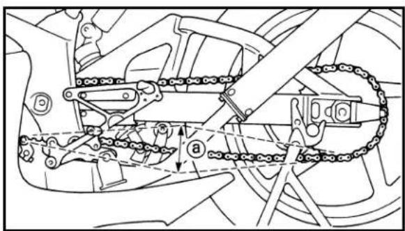
text_image
Technical diagram of a mechanical linkage system with labeled components and motion indicators
text_image
Technical diagram of a mechanical assembly with numbered components labeled ①, ②, and ③.- Install:
- Wheel axle ①
NOTE:
- Apply the lithium soap base grease on the wheel axle.
-
Insert the wheel axle from left side.
-
Install:
-
Plain washer ①
- Nut (wheel axle) ②
NOTE:
- Apply the lithium soap base grease on the wheel axle thread.
• Temporarily tighten the nut (wheel axle) at this point.
11.Adjust:
- Drive chain slack ⓐ

Drive chain slack: 40\~50 mm (1.6\~2.0 in)
Refer to "DRIVE CHAIN SLACK ADJUSTMENT" section in the CHAPTER 3.
12.Tighten:
- Nut (wheel axle) ①
| 80 Nm (8.0 m·kg, 58 ft·lb) |
| 2 Nm (0.2 m·kg, 1.4 ft·lb) |
| 16 Nm (1.6 m·kg, 11 ft·lb) |
NOTE:
- Tighten the axle nut while pushing down the drive chain.
- After tightening the axle nut, tighten the lock-nut with the turned out the adjuster.
13.Adjust:
- Wheel alignment Refer to "WHEEL ALIGNMENT ADJUSTMENT" section in the CHAPTER 3.
EC5A0000
① Brake hose removal
③ Master cylinder removal
② Caliper removal
| Extend of removal Order Part name Q'ty Remarks | ||||
| Preparation for Hold the machine by placingremoval the suitable stand. | FRONT BRAKE REMOVAL | ⚠WARNINGSupport the machine securely so there is no danger of it falling over. | ||
| Cowlng Refer to “COWLING, INDUCTIONInduction guide (left cylinder) GUIDE, SEAT AND FUEL TANK”Section in the CHAPTER 4.Drain the brake fluid. Refer to “REMOVAL POINTS”. | ||||
 | 1 Adapter 1ea.2 Union bolt 1 Loosen by moving the master cylinder3 Brake hose 1ea.4 Pad pin 1ea.5 Caliper 1ea.6 Brake lever 17 Reservoir tank 18 Reservoir hose 19 Master cylinder bracket 110 Master cylinder 1 | mounting position either way.Loosen when disassembling the caliper. | ||
EC5A8100
REAR BRAKE

text_image
7 Nm (0.7 m•kg, 5.1 ft•lb) 8 Nm (0.8 m•kg, 5.8 ft•lb) 14 Nm (1.4 m•kg, 10 ft•lb) 26 Nm (2.6 m•kg, 19 ft•lb) 30 Nm (3.0 m•kg, 22 ft•lb) 23 Nm (2.3 m•kg, 17 ft•lb) 20 Nm (2.0 m•kg, 14 ft•lb) 12 Nm (1.2 m•kg, 8.7 ft•lb) 18 Nm (1.8 m•kg, 13 ft•lb) 6 Nm (0.6 m•kg, 4.3 ft•lb)Extend of removal: ① Brake hose removal ② Caliper removal
③ Master cylinder removal
| Extend of removal Order Part name Q'ty Remarks | |||
| Preparation for Hold the machine by placingremoval the suitable stand. | ⚠WARNING ____Support the machine securely so there is no danger of it falling over.____ | ||
| Drain the brake fluid. Refer to “REMOVAL POINTS”. | |||
| 1 Brake hose holder 22 Adapter 13 Union bolt 14 Brake hose 15 Pad pin 16 Caliper 17 Brake pedal connecting bolt 18 Reservoir tank 19 Reservoir hose 110 Master cylinder | 1 | Loosen when disassembling the caliper. | |
EC5A8200
CALIPER DISASSEMBLY
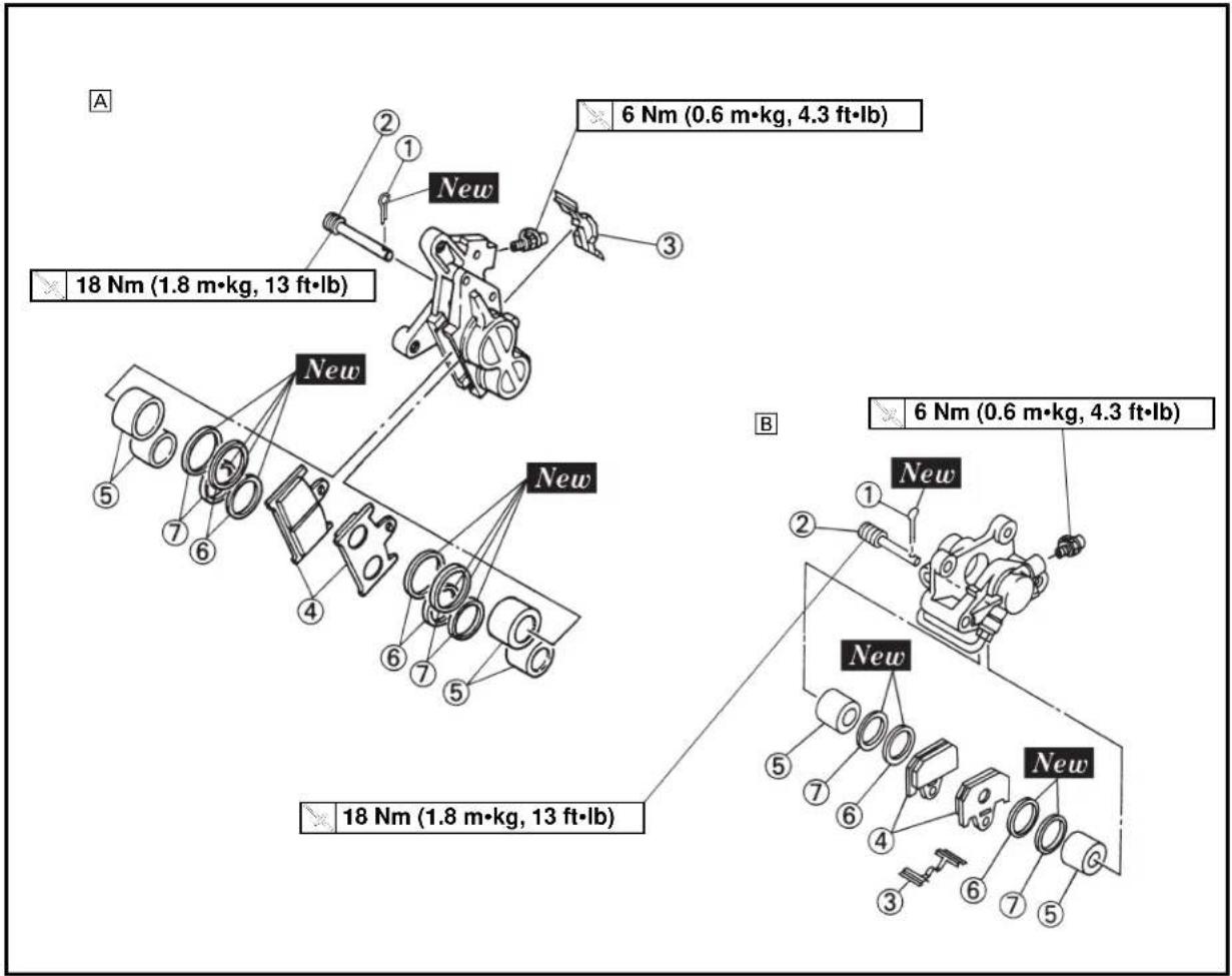
text_image
A 18 Nm (1.8 m·kg, 13 ft·lb) New 6 Nm (0.6 m·kg, 4.3 ft·lb) B 18 Nm (1.8 m·kg, 13 ft·lb) New 6 Nm (0.6 m·kg, 4.3 ft·lb) New 18 Nm (1.8 m·kg, 13 ft·lb)A Front
B Rear
Extend of removal: ① Front caliper disassembly
② Rear caliper disassembly
| Extend of removal Order Part name Q'ty Remarks | |||||
| 12 | CALIPER DISASSEMBLY A B | ||||
| 1 | Cotter pin | 1ea. | 1 | ||
| 2 | Pad pin | 1ea. | 1 | ||
| 3 | Pad support | 1ea. | 1 | ||
| 4 | Brake pad | 2ea. | 2 | ||
| 5 | Caliper piston | 4ea. | 2 | Refer to “REMOVAL POINTS”. | |
| 6 | Dust seal | 4ea. | 2 | } Refer to “REMOVAL POINTS”. | |
| 7 | Piston seal | 4ea. | 2 | ||
EC5A8300
MASTER CYLINDER DISASSEMBLY

text_image
A 6 Nm (0.6 m·kg, 4.3 ft·lb) B 2 Nm (0.2 m·kg, 1.4 ft·lb)A Front
B Rear
Extend of removal:
① Front master cylinder disassembly
② Rear master cylinder disassembly
| Extend of removal Order Part name Q'ty Remarks | ||||
| MASTER CYLINDER DISASSEMBLY | ||||
| 1 Master cylinder boot 12 Circlip 13 Master cylinder kit 1 | ||||
EC536000
HANDLING NOTE
WARNING
The brake components of this machine are suit for closed circuit use only. Never use on any public road.
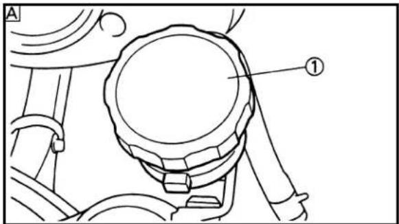
text_image
A ①
text_image
B ① UPPER LOWER
text_image
A ① ②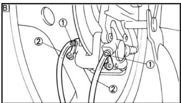
text_image
Technical diagram of a mechanical assembly with numbered components, likely illustrating a valve or clamp mechanism.EC5A3000
REMOVAL POINTS
EC5A3200
Brake fluid
- Remove:
- Reservoir tank cap ①
NOTE:
Do not remove the diaphragm.
A Front
B Rear
- Connect the transparent hose ② to the bleed screw ① and place a suitable container under its end.
A Front
B Rear
- Loosen the bleed screw and drain the brake fluid while pulling the lever in or pushing down on the pedal.
CAUTION:
- Do not reuse the drained brake fluid.
- Brake fluid may erode painted surfaces or plastic parts. Always clean up spilled fluid immediately.
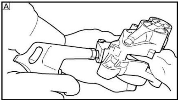
natural_image
Line drawing of hands holding a mechanical device with no visible text or symbols
natural_image
Line drawing of a hand using a tool to adjust or install a mechanical component (no text or symbols visible)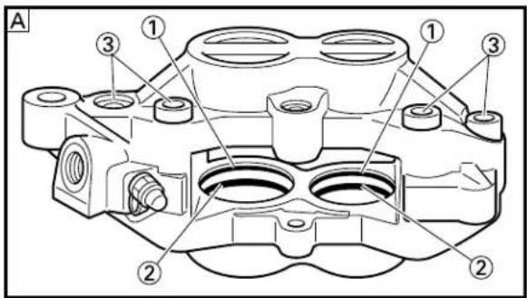
text_image
A ① ③ ② ② ① ③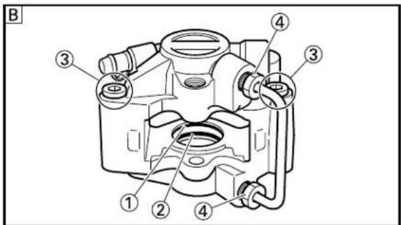
text_image
B ① ② ③ ④ ③EC533301
Caliper piston
- Remove:
- Caliper piston
Use compressed air and proceed carefully.
WARNING
- Cover piston with rag and use extreme caution when expelling piston from cylinder.
- Never attempt to pry out piston.
Caliper piston removal steps:
- Insert a piece of rag into the caliper to lock one caliper.
- Carefully force the piston out of the caliper cylinder with compressed air.
A Front
B Rear
EC543411
Piston seal kit
-
Remove:
-
Dust seal ①
- Piston seal ②
NOTE:
Remove the piston seals and dust seals by pushing them with a finger.
CAUTION:
- Never attempt to pry out piston seals and dust seals.
- Do not loosen the bolts ③ and nuts ④.
WARNING
Replace the piston seals and dust seals whenever a caliper is disassembled.
A Front
B Rear

natural_image
Technical line drawing of a mechanical component with labeled part 'a' (no text or symbols beyond label)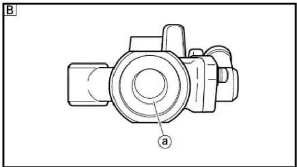
natural_image
Technical line drawing of a mechanical component with labeled part 'a' (no text or symbols beyond label)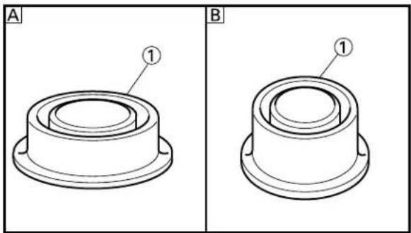
natural_image
Technical line drawings of a mechanical component, labeled A and B, showing cross-sectional views with no text or symbols.
text_image
A ② ① B ② ①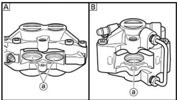
text_image
A B a aEC5A4000 INSPECTION
EC534112 Master cylinder
- Inspect:
- Master cylinder inner surface ① Wear/Scratches → Replace master cylinder assembly. Stains → Clean.
WARNING
Use only new brake fluid.
A Front
B Rear
- Inspect:
- Diaphragm ① Crack/Damage → Replace.
A Front
B Rear
- Inspect:
- Master cylinder piston ① - Master cylinder cup ② Wear/Damage/Score marks → Replace master cylinder kit.
A Front
B Rear
EC534214
Caliper
- Inspect:
- Caliper cylinder inner surface @ Wear/Score marks → Replace caliper assembly.
A Front
B Rear
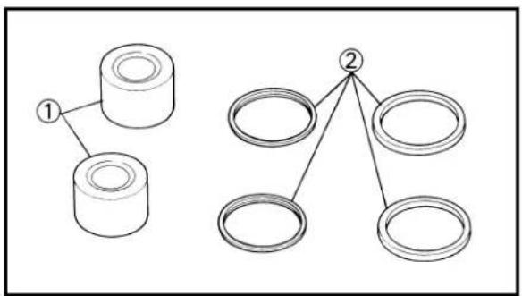
flowchart
graph TD
    A["1"] --> B["2"]
    C["1"] --> D["2"]
    E["2"] --> F["2"]
    G["2"] --> H["2"]
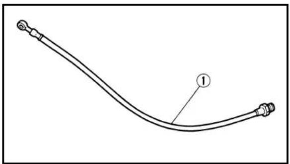
natural_image
Simple line drawing of a curved cable or pipe with two connectors, labeled with number 1 (no text or symbols on the diagram itself)- Inspect:
- Caliper piston ①
Wear/Score marks → Replace caliper piston assembly.
WARNING
Replace the piston seals and dust seals ② whenever a caliper is disassembled.
EC534301
Brake hose
- Inspect:
- Brake hose ①
Crack/Damage → Replace.
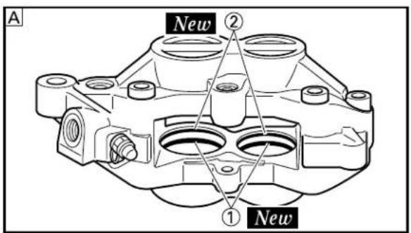
text_image
A New ② ① New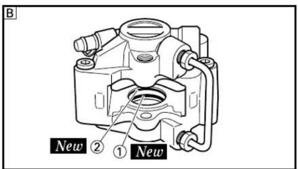
text_image
B New ② ① NewEC5A5000
ASSEMBLY AND INSTALLATION
WARNING
- All internal parts should be cleaned in new brake fluid only.
- Internal parts should be lubricated with brake fluid when installed.
- Replace the piston seals and dust seals whenever a caliper is disassembled.
EC535113
Caliper piston
-
Clean:
-
Caliper
- Piston seal
- Dust seal
- Caliper piston
Clean them with brake fluid.
-
Install:
-
Piston seal ① New
- Dust seal ② New
WARNING
Always use new piston seals and dust seals.
NOTE:
Fit the piston seals and dust seals onto the slot on caliper correctly.
A Front
B Rear
text_image
A ① ① ① a
text_image
B ① ① a
text_image
① ② ③ ④ New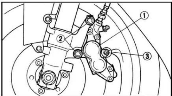
text_image
Technical diagram of a mechanical assembly with numbered components and labeled parts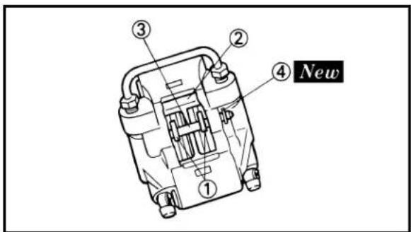
text_image
① ② ③ ④ New- Install:
- Caliper piston ①
NOTE:
Apply the brake fluid on the piston wall.
CAUTION:
• Install the piston with its shallow depressed side ⓐ facing the caliper.
- Never force to insert.
A Front
B Rear
EC535241
Front caliper
-
Install:
-
Brake pad ①
- Pad support ②
- Pad pin ③
- Cotter pin ④ New
NOTE:
Temporarily tighten the pad pin at this point.
-
Install:
-
Caliper ①
- Bolt (caliper) ②
35 Nm (3.5 m·kg, 25 ft·lb)
- Tighten:
- Pad pin ③
18 Nm (1.8 m·kg, 13 ft·lb)
EC545141
Rear caliper
-
Install:
-
Brake pad ①
- Pad support ②
- Pad pin ③
- Cotter pin ④ New
NOTE:
Temporarily tighten the pad pin at this point.
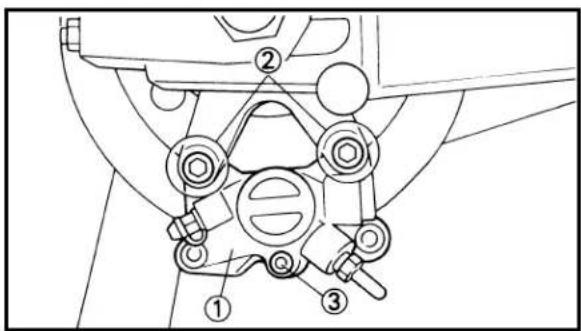
text_image
Technical diagram of a mechanical assembly with numbered components, likely illustrating a linkage or mounting mechanism.-
Install:
-
Caliper ①
- Bolt (caliper) ②
23 Nm (2.3 m·kg, 17 ft·lb)
- Tighten:
- Pad pin ③
18 Nm (1.8 m·kg, 13 ft·lb)
EC5A5230
Master cylinder kit
-
Clean:
-
Master cylinder
- Master cylinder kit
Clean them with brake fluid.

text_image
A ② ① ③ B ② ① ③- Install:
• Master cylinder cup (primary) ①
• Master cylinder cup (secondary) ②
To master cylinder piston ③.
NOTE:
Apply the brake fluid on the master cylinder cup.
WARNING
After installing, cylinder cup should be installed as shown direction. Wrong installation cause improper brake performance.

text_image
A ② ① ③ B ② ① ③A Front
B Rear
- Install:
- Spring ①
To master cylinder piston ②.
NOTE:
Install the spring at the smaller dia. side.
A Front
B Rear

text_image
A ① ② ③ ④ ⑤ a b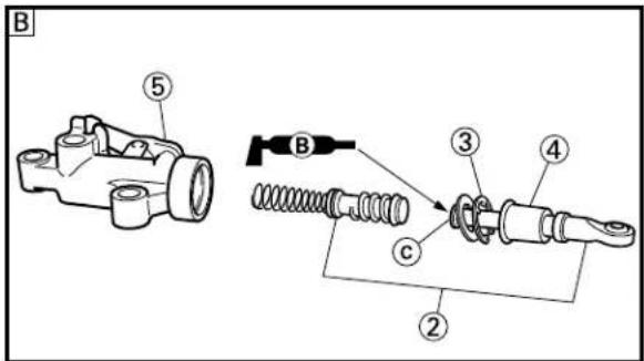
text_image
B ⑤ ② ③ ④ ③ ②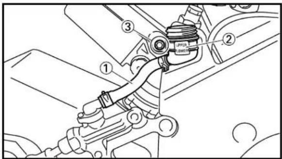
text_image
Technical diagram of a mechanical assembly with numbered components and labeled parts
text_image
Technical diagram of a mechanical assembly with numbered components, likely for assembly or maintenance instructions.
text_image
Technical diagram showing a hand using a tool to adjust or install a mechanical component, labeled with parts ①, ②, and ③.4. Install:
- Spring guide ①
- Master cylinder kit ②
- Circlip ③
- Master cylinder boot ④
To master cylinder ⑤.
NOTE:
- Apply the brake fluid on the master cylinder kit.
- Install the spring guide with the projection ① aligning with the master cylinder hole ⑥.
- Apply the lithium soap base grease on the tip © of the push rod.
- When installing the circlip, use a long nose circlip pliers.
A Front
B Rear
EC545270
Rear master cylinder
1. Install:
- Reservoir hose ①
- Reservoir tank ②
- Nut (reservoir tank) ③
7 Nm (0.7 m·kg, 5.1 ft·lb)
2. Install:
- Master cylinder ①
- Bolt (master cylinder) ②
20 Nm (2.0 m·kg, 14 ft·lb)
3. Install:
- Brake pedal ①
- Brake pedal connecting bolt ②
- Nut (brake pedal connecting bolt) ③
12 Nm (1.2 m·kg, 8.7 ft·lb)
NOTE:
After installing, check the brake pedal height. Refer to "REAR BRAKE ADJUSTMENT" section in the CHAPTER 3.

text_image
Technical diagram showing mechanical assembly steps with labeled parts and a 'New' label, likely illustrating a procedure or installation.
text_image
UP a b c ① ② ③
natural_image
Technical line drawing of a mechanical assembly with labeled component 'b' (no text or symbols beyond label)
text_image
Technical diagram showing mechanical assembly with labeled components and directional arrowsEC5A5A00
Front brake hose and master cylinder
- Install:
• Copper washer ① New
- Brake hose ②
- Union bolt ③
WARNING
Always use new copper washers.
NOTE:
-
Position the brake hoses with their paint marks ⓐ downward.
• Temporarily tighten the union bolt. -
Install:
-
Master cylinder ①
- Master cylinder bracket ②
- Bolt (master cylinder bracket) ③
NOTE:
- Install the bracket so that the arrow mark @ face upward.
- Temporarily tighten the bolt (master cylinder bracket).
CAUTION:
• Take care not to allow the brake hose metal fittings and union bolts to contact with other parts. If they are installed in contact with other parts, it will result in brake failure.
- Install the brake hoses with a clearance ⓑ of 2 mm (0.008 in) provided between their metal fittings.
- Install the brake hoses with a clearance © of 3 mm (0.012 in) between the union bolt and steering damper stay and a clearance ⓓ of 3 mm (0.012 in) between the brake hose (for the left caliper) and front fork.
-
Tighten:
-
Union bolt 30 Nm (3.0 m·kg, 22 ft·lb)
• Bolt (master cylinder bracket)
8 Nm (0.8 m·kg, 5.8 ft·lb)

text_image
① New- Install:
• Copper washer ① New
- Adapter ②
26 Nm (2.6 m·kg, 19 ft·lb)
- Brake hose ③ 14 Nm (1.4 m·kg, 10 ft·lb)
WARNING
The Ground Truth image displays a single, solid horizontal line. According to Rule 2 (UNDERSCORE & LINE RULES), if the GT contains lines used for stylistic emphasis or as background (like ruled paper), the OCR result must ignore them. The line in the GT is clearly a stylistic or background line, not a placeholder for text. Therefore, the OCR should not have output any underscores. Outputting `____` constitutes an error under Rule 2, as it hallucinates placeholder symbols where none are semantically intended. Hence, the OCR result is inconsistent with the Ground Truth.
Always use a new copper washer.
NOTE:
When turning the adapter over the brake hose, hold the brake hose so that it may not be twisted.
text_image
UPPER LOWER ① ② ③-
Install:
-
Reservoir tank ①
- Bolt (reservoir tank) ②
5 Nm (0.5 m·kg, 3.6 ft·lb)
- Reservoir hose ③

text_image
Technical diagram of a mechanical assembly with labeled parts and directional arrows indicating motion or assembly.-
Install:
-
Brake lever ①
- Bolt (brake lever) ②
1 Nm (0.1 m·kg, 0.7 ft·lb)
- Nut (brake lever) ③
6 Nm (0.6 m·kg, 4.3 ft·lb)
NOTE:
- Apply the lithium soap base grease on the bolt.
- When installing the brake lever, apply the molybdenum disulfide grease on the contacting surface of the master cylinder piston.

text_image
① New ② ③
text_image
Technical diagram of a vehicle's engine compartment with labeled parts a and b
text_image
① ② ③ New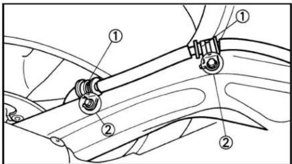
text_image
Technical diagram of a car suspension system with numbered components for mechanical assembly
natural_image
Technical line drawing of a mechanical assembly with labeled components (no readable text or symbols)EC545451
Rear brake hose
- Install:
• Copper washer ① New
- Brake hose ②
- Union bolt ③ 30 Nm (3.0 m·kg, 22 ft·lb)
30 Nm (3.0 m·kg, 22 ft·lb)
WARNING
Always use new copper washers.
CAUTION:
The Ground Truth image displays a single, solid horizontal line. According to Rule 2 (UNDERSCORE & LINE RULES), if the GT contains lines used for stylistic emphasis or as background elements (like ruled paper), the OCR result must ignore them. The provided OCR content is "____", which consists of four underscores. This is incorrect because underscores are not equivalent to a solid line and are not permitted under the “Stylistic/Background Lines (Ignore)” rule. Outputting underscores for a stylistic line violates the rule and constitutes an error. Therefore, the OCR result is inconsistent with the Ground Truth.
When installing the brake hose to the master cylinder, lightly touch the brake pipe with the projection on the master cylinder.
- Install:
• Copper washer ① New
- Adapter ② 26 Nm (2.6 m·kg, 19 ft·lb)
- Brake hose ③ 14 Nm (1.4 m·kg, 10 ft·lb)
WARNING
The Ground Truth image displays a single, solid horizontal line. According to Rule 2 (UNDERSCORE & LINE RULES), if the GT contains lines used for stylistic emphasis or as background (like ruled paper), the OCR result must ignore them. The line in the GT is clearly a stylistic or background line, not a placeholder for text. Therefore, the OCR should not have output any underscores. Outputting `____` constitutes an error under Rule 2, as it hallucinates placeholder symbols where none are semantically intended. No punctuation mismatch or formatting transformation applies here.
Always use a new copper washer.
NOTE:
When turning the adapter over the brake hose, hold the brake hose so that it may not be twisted.
-
Install:
-
Brake hose holder ①
- Bolt (brake hose holder) ②
8Nm (0.8 m·kg, 5.8 ft·lb)
- Install:
- Brake hose ①
Refer to "CABLE ROUTING DIAGRAM" section in the CHAPTER 2.

text_image
A UPPER LOWER a
text_image
B UPPER LOWER aEC5A5610
Brake fluid
- Fill:
- Brake fluid Until the fluid level reaches "LOWER" level line ⓐ.

Recommended brake fluid: DOT #4
WARNING
- Use only the designated quality brake fluid:
otherwise, the rubber seals may deteriorate, causing leakage and poor brake performance. - Refill with the same type of brake fluid; mixing fluids may result in a harmful chemical reaction and lead to poor performance.
- Be careful that water does not enter the master cylinder when refilling. Water will significantly lower the boiling point of the fluid and may result in vapor lock.
CAUTION:
Brake fluid may erode painted surfaces or plastic parts. Always clean up spilled fluid immediately.
A Front
B Rear
- Air bleed:
- Brake system Refer to "BRAKE SYSTEM AIR BLEEDING" section in the CHAPTER 3.
- Inspect:
- Brake fluid level Fluid at lower level → Fill up. Refer to “BRAKE FLUID LEVEL INSPEC-TION” section in the CHAPTER 3.
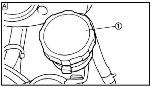
text_image
A ①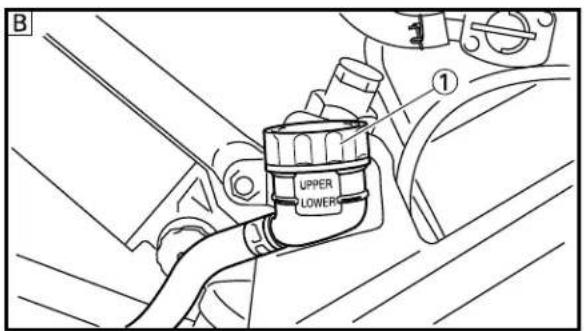
text_image
B ① UPPER LOWER-
Install:
-
Diaphragm
- Reservoir tank cap ①
CAUTION:
After installation, while pulling the lever in or pushing down on the pedal, check whether there is any brake fluid leaking where the union bolts are installed respectively at the master cylinder and caliper.
A Front
B Rear
EC550000
FRONT FORK

text_image
20 Nm (2.0 m·kg, 14 ft·lb) 10 Nm (1.0 m·kg, 7.2 ft·lb) 23 Nm (2.3 m·kg, 17 ft·lb) 8 Nm (0.8 m·kg, 5.8 ft·lb)Extend of removal: ① Front fork removal
| Extend of removal Order Part name Q'ty Remarks | ||||
| Preparation for Hold the machine by placingremoval the suitable stand. | FRONT FORK REMOVAL | ⚠WARNINGSupport the machine securely so there is no danger of it falling over. | ||
| Cowling Refer to “COWLING, INDUCTIONInduction guide (left cylinder) GUIDE, SEAT AND FUEL TANK” section in the CHAPTER 4.Front caliper Refer to “FRONT BRAKE AND FRONT wheel Refer to “FRONT WHEEL AND REAR BRAKE” section. | ||||
| 1 | Front fender | 1 | ||
| 2 | Pinch bolt (steering damper stay) | 1 | ||
| 3 | Pinch bolt (handlebar) | 2 | ||
| 4 | Pinch bolt (handle crown) | 1 | ||
| 5 | Cap bolt | 1 | ||
| 6 | Pinch bolt (under bracket) | 2 | ||
| 7 | Front fork | 1 | ||
EC558000
FRONT FORK DISASSEMBLY
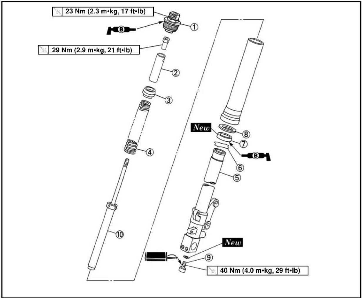
text_image
23 Nm (2.3 m·kg, 17 ft·lb) 29 Nm (2.9 m·kg, 21 ft·lb) New 40 Nm (4.0 m·kg, 29 ft·lb)Extend of removal: ① Oil seal removal ② Damper rod removal
| Extend of removal Order Part name Q'ty Remarks | ||||
 | FRONT FORK DISASSEMBLY | Refer to “REMOVAL POINTS”. | ||
| 1 | Cap bolt 1 Use special tool. | |||
| 2 | pacer 1 | |||
| 3 | pacer guide 1 | |||
| 4 | Fork spring | 1 | Drain the fork oil. | |
| 5 | Inner tube | 1 | ||
| 6 | $stopper ring | 1 | Refer to “REMOVAL POINTS”. | |
| 7 | Oil seal | 1 | ||
| 8 | Oil seal washer | 1 | ||
| 9 | Bolt (damper rod) | 1 Use special tool. | ||
| 10 | Damper rod | 1 Refer to “REMOVAL POINTS”. | ||
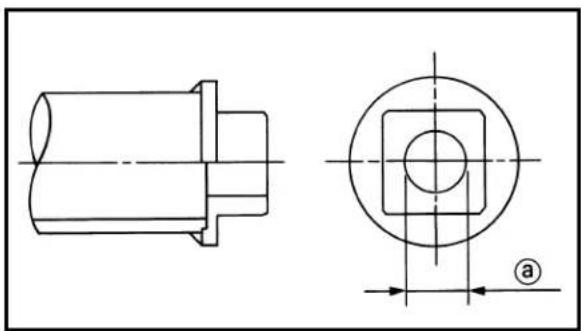
natural_image
Technical drawing of a mechanical part with front and top views (no text or symbols)EC556010
HANDLING NOTE
NOTE:
- With the 97 or later models, the dampar rod diameter is 12.5 ~mm (0.49 in). If the dimension a of your dampar rod holders is 12 ~mm (0.47 in), drill it to expand its diameter to 14 mm (0.55 in). - The front fork requires careful attention. So it is recommended that the front fork be maintained at the dealers.
CAUTION:
To prevent an accidental explosion of air, the following instructions should be observed:
- The front fork with a built-in piston rod has a very sophisticated internal construction and is particularly sensitive to foreign material.
Use enough care not to allow any foreign material to come in when the oil is replaced or when the front fork is disassembled and reassembled.
- Before removing the cap bolts or front forks, be sure to extract the air from the air chamber completely.

natural_image
Technical line drawing of a mechanical component with a labeled part (1), showing internal structure without any text or symbols.EC553000
REMOVAL POINTS
EC553144
Cap bolt
- Remove:
- Cap bolt ①
From the outer tube.
NOTE:
Before removing the front fork from the machine, loosen the cap bolt.
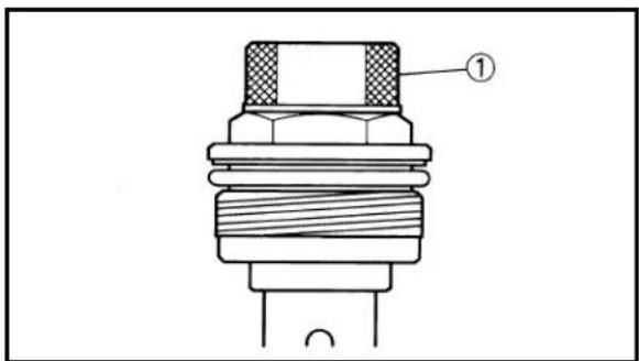
text_image
Technical diagram of a mechanical component with labeled part 1- Loosen:
- Spring preload adjuster ①
NOTE:
Record the set position of the adjuster (the amount of turning out the adjuster to the fully turned out position) before loosening it.
FRONT FORK


text_image
Technical diagram of a mechanical device with numbered components for identification- Remove:
- Cap bolt ①
NOTE:
- While pressing down the spacer ③ with the fork spring compressor ②, set the rod holder ⑤ between the locknut ④ and spacer.
- Hold the locknut and remove the cap bolt by turning the spring preload adjuster ⑥.

Fork spring compressor:
YM-1441/90890-01441
Rod holder:
YM-1434/90890-01434
text_image
Diagram showing two hands holding a cylindrical object with labeled parts ① and ②, indicating a movement or force direction.EC553212
Oil seal
- Remove:
- Inner tube ① Pull out the inner tube from the outer tube ②.

natural_image
Line drawing of a hand holding a tool interacting with a cylindrical object (no text or symbols)- Remove:
- Stopper ring ① Using slotted-head screwdriver.
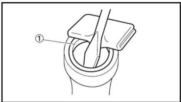
natural_image
Diagram of a mechanical assembly with labeled component (①), showing a looped joint and clamping mechanism (no text or symbols beyond label)- Remove:
- Oil seal ① - Oil seal washer Using slotted-head screwdriver.
CAUTION:
• Take care not to scratch the outer tube inner surface.
- Replace the oil seal whenever removed.

natural_image
Technical line drawing of a mechanical component with threaded end and labeled part (1), no text or symbols present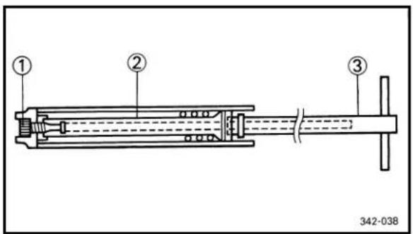
text_image
① ② ③ 342-038
natural_image
Line drawing of a mechanical component with a threaded end and labeled part (1), no text or symbols present.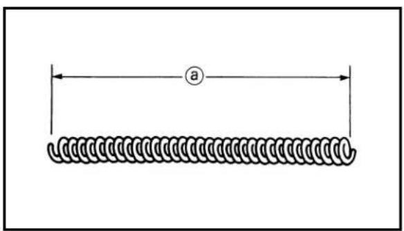
natural_image
Diagram of a coiled spring with labeled dimension 'a' (no text or symbols beyond label)EC553322
Damper rod
- Remove:
- Locknut ①
-
Remove:
-
Bolt (damper rod) ①
- Damper rod ②
NOTE:
Use a damper rod holder ③ to lock the damper rod.

Damper rod holder: YM-1425/90890-01425
EC554000
INSPECTION
EC554100
Damper rod
- Inspect:
- Damper rod ①
Bend/Damage → Replace damper rod.
CAUTION:
The front fork with a built-in piston rod has a very sophisticated internal construction and is particularly sensitive to foreign material.
Use enough care not to allow any foreign material to come in when the oil is replaced or when the front fork is disassembled and reassembled.
EC554400
Fork spring
- Measure:
- Fork spring free length ⓐ
Out of specification → Replace.

Fork spring free length:
Standard
212.5 mm 210.5 mm
(8.37 in) (8.29 in)

text_image
Technical diagram of a mechanical device with labeled parts and measurement scaleEC554502
Inner tube
1. Inspect:
- Inner tube surface @ Score marks → Repair or replace. Use #1,000 grit wet sandpaper. Damaged oil lock piece → Replace. - Inner tube bends Out of specification → Replace. Use the dial gauge ①.

Inner tube bending limit: 0.2 mm (0.008 in)
NOTE:
The bending value is shown by one half of the dial gauge reading.
WARNING
Do not attempt to straighten a bent inner tube as this may dangerously weaken the tube.

text_image
Technical diagram of a cylindrical pipe with three labeled parts: ①, ②, and ③.EC554611
Outer tube
1. Inspect:
- Outer tube ①
- Piston metal ②
- Slide metal ③
Damage/Score marks/Wear → Replace outer tube assembly.
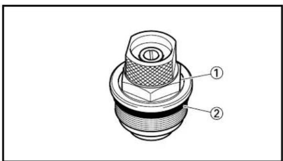
text_image
Technical diagram of a mechanical component with labeled parts ① and ②EC554710
Cap bolt
1. Inspect:
- Cap bolt ①
- O-ring ②
Wear/Damage → Replace.
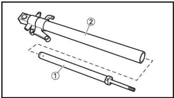
text_image
Technical diagram of a mechanical assembly with labeled parts ① and ②, showing exploded and assembled views.EC555000
ASSEMBLY AND INSTALLATION
EC555191
Front fork assembly
-
Wash the all parts in a clear solvent.
-
Install:
- Damper rod ①
To inner tube ②.
CAUTION:
To install the damper rod into the inner tube, hold the inner tube aslant. If the inner tube is held vertically, the damper rod may fall into it, damaging the valve inside.
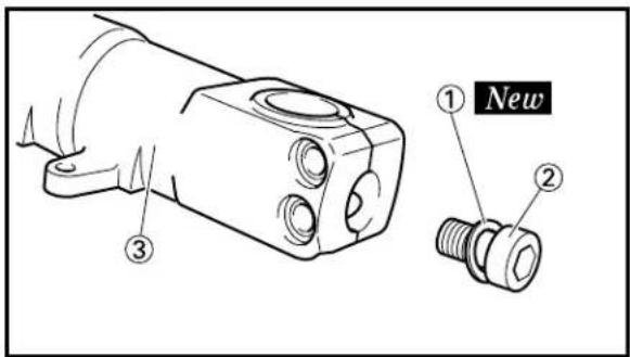
text_image
① New ② ③- Install:
• Copper washer ① New
- Bolt (damper rod) ②
To inner tube ③.
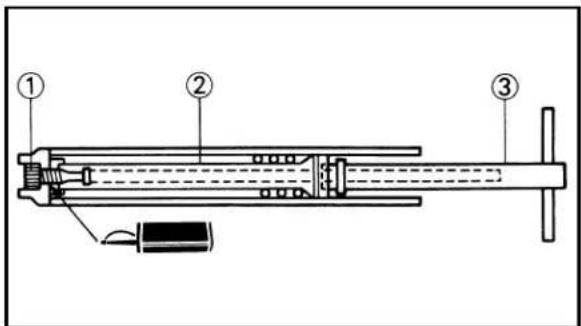
text_image
Technical diagram of a mechanical device with numbered components labeled ①, ②, and ③.- Tighten:
- Bolt (damper rod) ①

NOTE:
Use a damper rod holder ③ to lock the damper rod ②.

text_image
Technical diagram of a mechanical component with labeled parts and an inset showing a detailed view of a bolt head.
Damper rod holder: YM-1425/90890-01425
- Install:
- Locknut ① To damper rod ②.
NOTE:
Install the locknut with its width across flat ① facing upward.
FRONT FORK


text_image
① ② New ③ ④
text_image
Technical diagram of a mechanical component with labeled parts ① and ②
text_image
Technical diagram of a mechanical assembly with numbered components for identification
natural_image
Technical line drawing of a pipe fitting with a circular component labeled '1' (no text or symbols beyond label)
text_image
Technical diagram showing a hand operating a mechanical component with labeled parts ① and ②6. Install:
- Stopper ring ①
- Oil seal ② New
- Oil seal washer ③
To inner tube ④.
NOTE:
- Apply the fork oil on the inner tube.
- When installing the oil seal, use vinyl seat ⓐ with fork oil applied to protect the oil seal lip.
- Install the oil seal with its manufacture's marks or number facing the axle holder side.
7. Install:
- Inner tube ① To outer tube ②.
CAUTION:
When installing the inner tube, slowly and take care to insert it carefully so that the slide metal ③ and piston metal ④ will not be scratched.
8. Install:
- Oil seal washer ① To outer tube slot.
9. Install:
- Oil seal ①
NOTE:
Press the oil seal into the outer tube with fork seal driver ②.

Fork seal driver: YM-1442/90890-01442
FRONT FORK

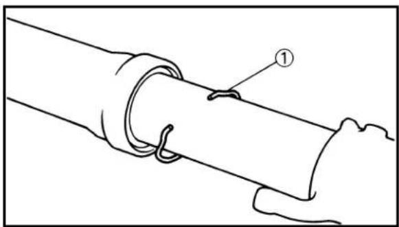
natural_image
Diagram of a pipe joint with a labeled component (①), showing rope and seal details (no text or symbols beyond label)
natural_image
Illustration of two hands performing a physical maneuver on a cylindrical object, with an arrow indicating motion direction (no text or symbols)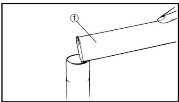
natural_image
Diagram of a pipe being inserted into a cylindrical pipe, showing a tool and labeled point (1) — no text or symbols present.
text_image
Technical diagram of a mechanical assembly with numbered components and directional arrow indicating movement or force- Install:
- Stopper ring ①
NOTE:
Fit the stopper ring correctly in the groove in the outer tube.
11.Check:
- Inner tube smooth movement Tightness/Binding/Rough spots → Repeat the steps 2 to 10.
- Compress the front fork fully.
13.Fill:
- Front fork oil Until outer tube top surface with recommended fork oil ①.

Recommended oil: Suspension oil "01"
CAUTION:
- Be sure to use recommended fork oil. If other oils are used, they may have an excessively adverse effect on the front fork performance.
-
Never allow foreign materials to enter the front fork.
-
After filling, pump the damper rod ① slowly up and down more than 10 times to distribute the fork oil.
NOTE:
Use the rod puller ② and rod puller attachment ③ to pull up and down the damper rod.

Rod puller ②: YM-1437/90890-01437 Rod puller attachment ③: 90890-01435
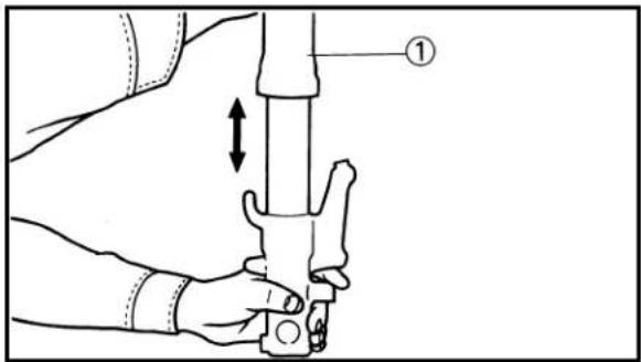
text_image
Technical diagram showing a hand holding a tool with an arrow indicating direction and labeled point ①
text_image
Technical diagram of a mechanical assembly with labeled parts and dimension annotations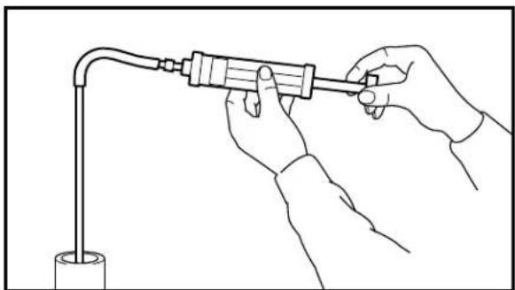
natural_image
Line drawing of hands holding a tool with a tube, connected to a pipe (no text or symbols)15.Fill:
- Front fork oil
Until outer tube top surface with recommended fork oil once more.
- After filling, pump the outer tube ① slowly up and down (about 60 mm (2.4 in) stroke) to distribute the fork oil once more.
NOTE:
Be careful not to excessive full stroke. A stroke of 60 mm (2.4 in) or more will cause air to enter. In this case, repeat the steps 13 to 16.
- Wait ten minutes until the air bubbles have been removed from the front fork, and the oil has dispense evenly in system before setting recommended oil level.
NOTE:
Fill with the fork oil up to the top end of the outer tube, or the fork oil will not spread over to every part of the front forks, thus making it impossible to obtain the correct level. Be sure to fill with the fork oil up to the top of the outer tube and bleed the front forks.
18.Measure:
- Oil level (left and right) ⓐ
Out of specification → Adjust.

Standard oil level:
135 mm (5.31 in)
Extent of adjustment:
97\~157 mm (3.82\~6.18 in)
From top of outer tube with inner
tube and damper rod ① fully compressed without spring.
WARNING
Never fail to make the oil level adjustment between the maximum and minimum level and always adjust each front fork to the same setting. Uneven adjustment can cause poor handling and loss of stability.
FRONT FORK


text_image
Technical diagram showing exploded view of a mechanical assembly with labeled parts 1, 2, and 3
text_image
Technical diagram of a mechanical assembly with numbered components for identification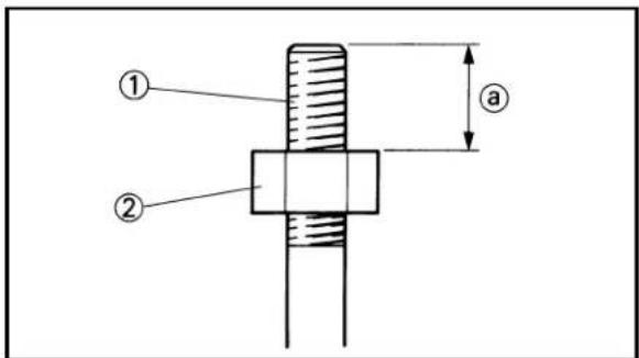
text_image
Technical diagram showing a mechanical assembly with labeled parts and dimension annotation
text_image
Technical diagram of a mechanical component with labeled parts and an inset showing a cross-sectional view.-
Install:
-
Fork spring ①
- Spacer guide ②
- Spacer ③
NOTE:
Install the fork spring with its smaller dia. portion upward.
20.Attach:
- Rod puller ①
- Rod puller attachment ②
- Fork spring compressor ③
- Rod holder ④
NOTE:
- Pull up the damper rod with the rod puller and rod puller attachment.
- While pressing down the spacer ⑤ with the fork spring compressor, set the rod holder between the locknut ⑥ and spacer.

Rod puller ①:
YM-1437/90890-01437
Rod puller attachment ②: 90890-01435
Fork spring compressor ③: YM-1441/90890-01441
Rod holder ④: YM-1434/90890-01434
21.Adjust:
- Distance ⓐ
Out of specification → Turn the locknut ② until the specified distance is obtained.

Distance ⓐ:
13 mm (0.51 in)
Between damper rod ① top and locknut ② top.
22.Adjust:
- Rebound damping adjuster position ① Out of specification → Turn the adjuster ① until the specified position is obtained.

Rebound damping adjuster position ⓐ:
Zero mm (Zero in)
NOTE:
Record the set position of the adjuster (the amount of turning in the adjuster to the fully turned in position) before adjusting it.
CAUTION:
If the rebound damping adjuster position is out of specification, proper damping force cannot be obtained.

text_image
Technical diagram of a mechanical valve or actuator with numbered components labeled 1 to 4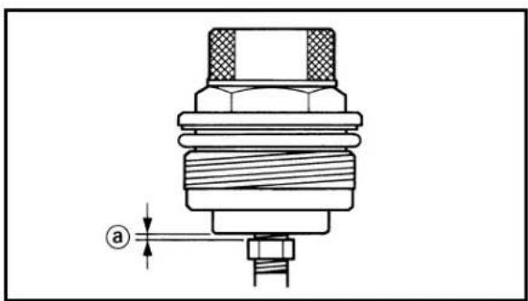
text_image
a-
Install:
-
Push rod ①
- Cap bolt ②
NOTE:
Turn in the cap bolt fully by holding the spring preload adjuster ④ with your hand until the rebound damping adjuster ③ hits the push rod tip.
- Check:
- Cap bolt clearance ⓐ
Out of specification → Repeat the steps 21 to 23.

Cap bolt clearance ⓐ: Zero\~2 mm (Zero\~0.08 in)
CAUTION:
If the cap bolt is installed out of specification, proper damping force cannot be obtained.
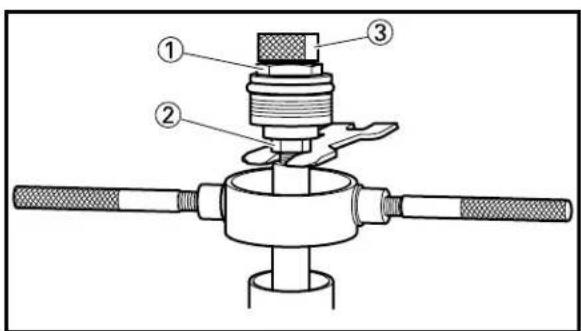
text_image
Technical diagram of a mechanical device with numbered components, likely a valve or actuator assembly.- Install:
- Cap bolt (locknut) ①
29 Nm (2.9 m·kg, 21 ft·lb)
NOTE:
Hold the locknut ② and tighten the cap bolt by turning the spring preload adjuster ③ with specified torque.
CAUTION:
Do not tighten the cap bolt. It may cause damage to the spring preload adjuster.
FRONT FORK

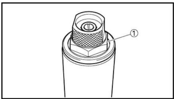
natural_image
Technical line drawing of a mechanical component with a labeled part (1), showing no text or symbols beyond the label.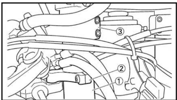
text_image
Technical diagram of automotive engine components with numbered parts labeled ①, ②, and ③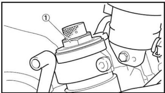
natural_image
Technical line drawing of a mechanical device with a labeled component (no text or symbols present)
text_image
Technical schematic diagram of a mechanical device with labeled components (a, b, c) and dimension arrows- Install:
- Cap bolt ①
To outer tube.
NOTE:
Temporarily tighten the cap bolt.
EC555290
Installation
-
Install:
-
Front fork ①
- Steering damper stay ② (right side only)
- Handlebar ③
NOTE:
- Temporarily tighten the pinch bolt (under bracket).
-
Do not tighten the pinch bolts (handle crown, steering damper stay and handlebar) yet.
-
Tighten:
- Cap bolt ①
23 Nm (2.3 m·kg, 17 ft·lb)
-
Adjust:
-
Front fork top end ⓐ
- Handlebar position ⑥
- Steering damper stay position © (left side only)

Front fork top end:
13 mm (0.51 in)
Handlebar position:
9 mm (0.35 in)
Steering damper stay position:
73 mm (2.87 in)
Refer to "FRONT FORK TOP END ADJUSTMENT" in the CHAPTER 3.
FRONT FORK


text_image
Technical diagram showing mechanical assembly with numbered components and labeled parts
natural_image
Technical line drawing of a mechanical assembly with rotating components (no text or symbols)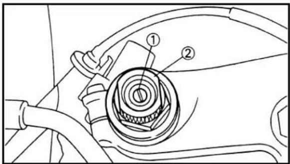
text_image
Technical diagram of a mechanical component with numbered parts, likely illustrating a gear or valve assembly.
text_image
Technical diagram of a mechanical assembly with numbered components, likely for assembly or maintenance instructions.4. Tighten:
- Pinch bolt (handle crown) ①
20 Nm (2.0 m·kg, 14 ft·lb)
- Pinch bolt (under bracket) ②
23 Nm (2.3 m·kg, 17 ft·lb)
- Pinch bolt (handlebar) ③
7 Nm (0.7 m·kg, 5.1 ft·lb)
- Pinch bolt (steering damper stay) ④ (right side only) 10 Nm (1.0 m·kg, 7.2 ft·lb)
Refer to "FRONT FORK TOP END ADJUSTMENT" in the CHAPTER 3.
5. Check:
• Steering smooth action
Turn the handlebar to make sure no parts are being contacted with others.
Contact → Repair.
6. Adjust:
- Rebound damping force
- Spring preload
NOTE:
- Turn in the rebound damping adjuster ① fully, then turn out it to the originally set position.
- Turn in the spring preload adjuster ② to the originally set position.
7. Install:
- Front fender ①
- Bolt (front fender) ②
8 Nm (0.8 m·kg, 5.8 ft·lb)
EC5B0000
HANDLEBAR

text_image
7 Nm (0.7 m·kg, 5.1 ft·lb) 7 Nm (0.7 m·kg, 5.1 ft·lb) 2 Nm (0.2 m·kg, 1.4 ft·lb) 8 Nm (0.8 m·kg, 5.8 ft·lb)Extend of removal: ① Handlebar removal ② Throttle disassembly
| Extend of removal Order Part | name Q'ty Remarks | ||||
| Preparation for Cowling removal Induction guide | HANDLEBAR REMOVALto "COWLING, INDUCTIONlinder) GUIDE, SEAT AND FUEL | TANK" | section in the CHAPTER 4. | ||
| Handle crown Refer to "STEERING" section. | |||||
 | 1 Clutch cable2 Clutch lever holder3 Main switch4 Grip (left)5 Starter cable6 Starter lever7 Master cylinder8 Grip cap (upper)9 Throttle cable10 Throttle11 Grip cap (lower)12 Grip end13 Handlebar14 Grip (right)15 Tube guide 1 | 1111111111111111111111111111111111111111111111111111111111111111111111111111111111111111111111111111 | Disconnect at the lever side.Refer to "REMOVAL POINTS".Disconnect at the lever side.Refer to "REMOVAL POINTS". | ||
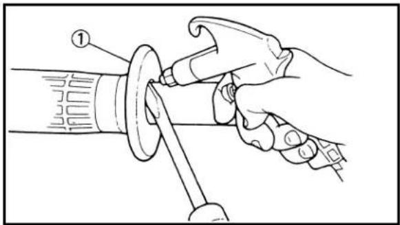
natural_image
Illustration of a hand using a tool to adjust or install a mechanical component, no text or symbols present
natural_image
Technical line drawing of a mechanical lever or tool with a handle and circular component (no text or symbols)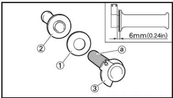
text_image
6mm(0.24in) a ① ② ③EC5B3000
REMOVAL POINTS
EC5B3200
Grip
- Remove:
• Grip ①
NOTE:
Blow in air between the handlebar or tube guide and the grip. Then remove the grip which has become loose.
EC5B4000
INSPECTION
EC5B4100
Handlebar
- Inspect:
- Handlebar ① Bends/Cracks /Damage → Replace.
WARNING
Do not attempt to straighten a bent handlebar as this may dangerously weaken the handlebar.
EC5B5000
ASSEMBLY AND INSTALLATION
EC5B5110
Throttle assembly
- Install:
- Ring plate ① - Grip (right) ② Apply the adhesive on the tube guide ③.
NOTE:
Before applying the adhesive, wipe off grease or oil on the tube guide surface ① with a lacquer thinner.
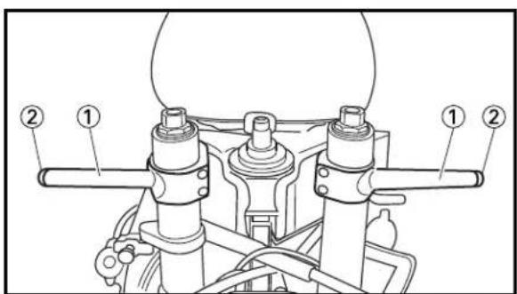
text_image
Technical diagram of a mechanical assembly with numbered components labeled ① and ②EC5B5230
Handlebar
- Install:
- Handlebar ① - Grip end ②
NOTE:
Temporarily tighten the bolts (handlebar).
HANDLEBAR


text_image
Diagram of a hand holding a medical or laboratory device with labeled parts (1, 2, 3, and a)
text_image
Technical diagram showing a hand holding a tool labeled '①' with a magnified view of the component 'B', likely illustrating a mechanical or electrical assembly.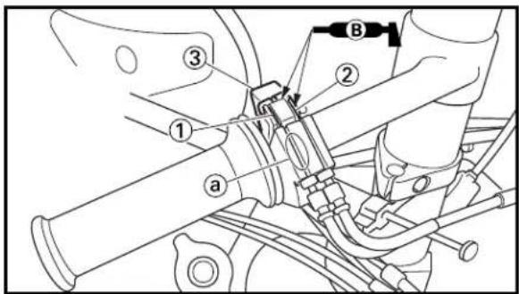
text_image
Technical diagram of a mechanical assembly with labeled parts and directional arrows indicating motion or movement.
text_image
Technical diagram of a mechanical device with labeled parts (a, b, c) and numbered components.2. Install:
- Throttle cable [carburetor (left cylinder)] ①
- Throttle cable [carburetor (right cylinder)]
②
To grip cap (lower) ③.
NOTE:
Install the throttle cable [carburetor (left cylinder)] in the grip side slit ⓐ in the grip cap (lower).
3. Install:
- Throttle ①
NOTE:
Apply the lithium soap base grease on the throttle grip sliding surface.
4. Install:
- Throttle cable [carburetor (left cylinder)] ①
- Throttle cable [carburetor (right cylinder)] ② To tube guide ③.
NOTE:
- Apply the lithium soap base grease on the throttle cable ends and tube guide cable widening portions.
- Install the throttle cable [carburetor (left cylinder)] in the grip side slit ⓐ in the tube guide.
5. Install:
- Grip cap (upper) ①
- Bolt (grip cap) ②
NOTE:
- Align the contacting surface ⓐ of the grip cap (upper) with the punch mark ⓑ on the handlebar.
- Tighten the bolts so that the upper side contacting surface © is closed.
6. Adjust:
- Throttle grip free play Refer to "THROTTLE CABLE ADJUSTMENT" section in the CHAPTER 3.
HANDLEBAR

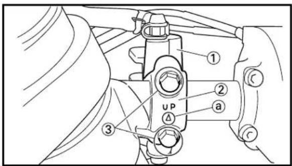
text_image
UP A a ① ② ③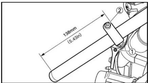
text_image
138mm (5.43in)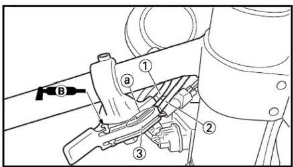
text_image
Technical diagram showing mechanical assembly with labeled parts and tool path indicator B7. Install:
- Master cylinder ①
• Master cylinder bracket ② - Bolt (master cylinder bracket) ③
8 Nm (0.8 m·kg, 5.8 ft·lb)
NOTE:
Install the bracket so that the arrow mark ⓐ faces upward.
8. Install:
- Starter lever ①
- Screw (starter lever) ②
NOTE:
The starter lever should be installed according to the dimension shown.
9. Install:
- Starter cable [carburetor (left cylinder)] ①
- Starter cable [carburetor (right cylinder)] ② To starter lever ③.
NOTE:
- Apply the lithium soap base grease on the starter lever ends.
- Install the starter cable [carburetor (left cylinder)] in the upper side slit ⓐ in the starter lever.

text_image
Technical diagram of a mechanical assembly with labeled parts ①, ②, and a10. Install:
- Grip (left) ①
Apply the adhesive to the handlebar ②.
NOTE:
Before applying the adhesive, wipe off grease or oil on the handlebar surface ⓐ with a lacquer thinner.
HANDLEBAR


text_image
② ③ 4mm (0.16in) ⑤ 8mm (0.31in) ④ ⑤ ①11.Install:
- Main switch ①
- Main switch holder ②
- Screw (main switch holder) ③
2 Nm (0.2 m·kg, 1.4 ft·lb)
- Clutch lever holder ④
- Bolt (clutch lever holder) ⑤
5 Nm (0.5 m·kg, 3.6 ft·lb)
NOTE:
The main switch and clutch lever holder should be installed according to the dimensions shown.
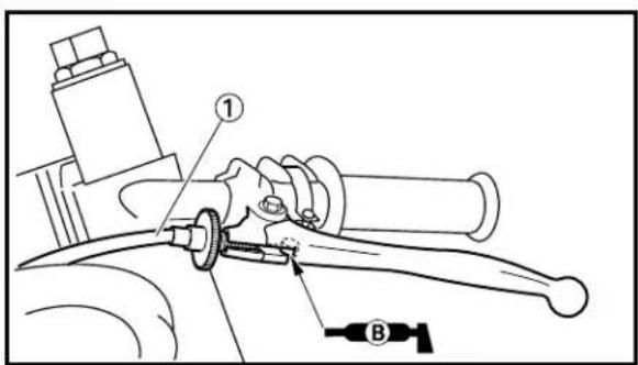
text_image
Technical diagram of a mechanical assembly with labeled parts ① and ②, showing components like a tool and a valve.12. Install:
- Clutch cable ①
NOTE:
Apply the lithium soap base grease on the clutch cable end.
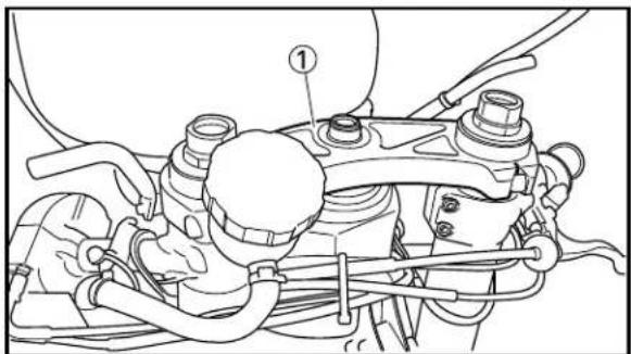
text_image
Technical diagram of an engine assembly with labeled component ①13. Install:
- Handle crown ①
Refer to "STEERING" section.
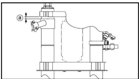
natural_image
Technical line drawing of a mechanical device with no visible text or symbols14.Adjust:
- Handlebar position ⓐ

Handlebar position: 9 mm (0.35 in)
HANDLEBAR

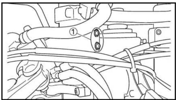
natural_image
Technical line drawing of a mechanical assembly with hoses and connectors (no text or symbols)15.Tighten:
- Pinch bolt (handlebar) ①
7 Nm (0.7 m·kg, 5.1 ft·lb)
CAUTION:
Tighten the pinch bolts to specified torque. If torque too much, it may cause the front fork to malfunction.
16.Adjust:
- Clutch lever free play
Refer to "CLUTCH ADJUSTMENT" section in the CHAPTER 3.
- Lock the throttle cables and starter cables using a locking wire.
Refer to "LOCKING WIRE INSTALLATION GUIDE" section in the CHAPTER 3.
EC560000
STEERING
EC568000
HANDLE CROWN AND STEERING DAMPER
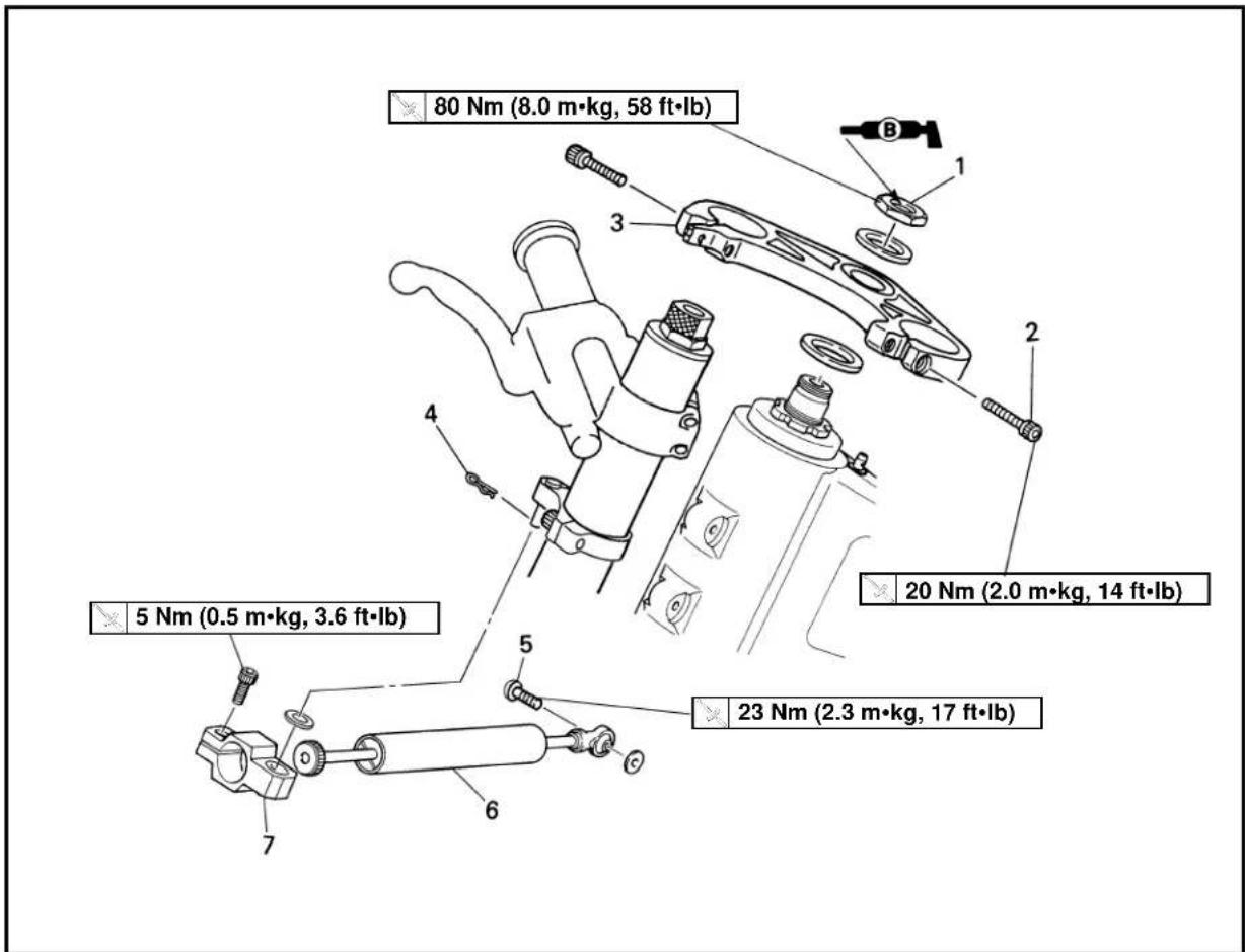
text_image
80 Nm (8.0 m·kg, 58 ft·lb) 20 Nm (2.0 m·kg, 14 ft·lb) 5 Nm (0.5 m·kg, 3.6 ft·lb) 23 Nm (2.3 m·kg, 17 ft·lb)Extend of removal: ① Handle crown removal ② Steering damper removal
| Extend of removal Order Part | name Q'ty Remarks | |||
| Preparation for Hold the machine removal the suitable stand. | HANDLE CROWN AND STEERING DAMPER REMOVALby placingCowling Refer to “COWLING, INDUCTIONInduction guide (left cylinder) GUIDE, SEAT AND FUEL TANK” section in the CHAPTER 4.Bolt (Front brake reservoir tank)Front brake caliper Refer to “FRONT BRAKE AND FRONT WHEEL AND FRONT weler Refer to “FRONT WHEEL AND FRONT fender | ⚠WARNINGSupport the machine securely so there is no danger of it falling over. | ||
| [IMAGE] | 1 | Steering shaft nut 1 | Only loosening. | |
| 2 | Pinch bolt (handle crown) | 2 | ||
| 3 | Handle crown | 1 | ||
| 4 | Clip | 1 | ||
| 5 | Bolt (steering damper) | 1 | ||
| 6 | Steering damper | 1 | ||
| 7 | Steering damper bracket | 1 | ||
EC568100
UNDER BRACKET

text_image
7 Nm (0.7 m·kg, 5.1 ft·lb) TIGHTENING STEPS: • Tighten ring nut. 46 Nm (4.6 m·kg, 33 ft·lb) • Loosen it one turn. • Retighten it. 1 Nm (0.1 m·kg, 0.7 ft·lb) 10 Nm (1.0 m·kg, 7.2 ft·lb) 23 Nm (2.3 m·kg, 17 ft·lb)Extend of removal: ① Under bracket removal ② Bearing removal
| Extend of removal Order Part name Q'ty Remarks | ||||
 | UNDER BRACKET REMOVAL1 Pinch bolt (steering damper stay)2 Pin 13 Pinch bolt (handlebar) 4 Only loosening.4 Pinch bolt (under bracket) 4 Only loosening.5 Front fork 2 Refer to “FRONT FORK” section.6 Ring nut 1 Use special tool.7 Under bracket 18 Inner fender 19 Ball race cover 110 Bearing (upper) 111 Bearing (lower) 1 Refer to “REMOVAL POINTS”.12 Ball race 2 Refer to “REMOVAL POINTS”. | 1 Only loosening. | ||
| Refer to “REMOVAL POINTS”. | ||||

text_image
Technical diagram of a mechanical assembly with labeled parts ① and ②EC563000
REMOVAL POINTS
EC563202
Ring nut
- Remove:
- Ring nut ①
Use the ring nut wrench ②.

Ring nut wrench: YU-33975/90890-01403
WARNING
Support the steering shaft so that it may not fall down.
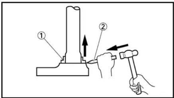
text_image
Technical diagram showing two hands operating a mechanical press or fixture with numbered annotations and directional arrows indicating movement.EC563300
Bearing (lower)
- Remove:
- Bearing (lower) ①
Use the floor chisel ②.
CAUTION:
Take care not to damage the steering shaft thread.
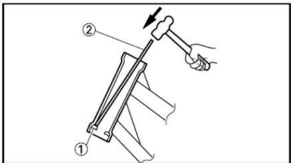
text_image
Technical diagram showing a hand using a hammer to lift a wooden plank, labeled with parts ① and ②.EC563400
Ball race
- Remove:
- Ball race ①
Remove the ball race using long rod ② and the hammer.

text_image
Technical diagram of a mechanical component with labeled parts, showing a shaft and base assembly.EC564000
INSPECTION
EC564200
Steering shaft
- Inspect:
- Steering shaft ①
Bend/Damage → Replace.

natural_image
Technical illustration of a mechanical assembly with a finger pressing a button (no text or symbols)
natural_image
Technical line drawing of a mechanical component with labeled part (1), no text or symbols present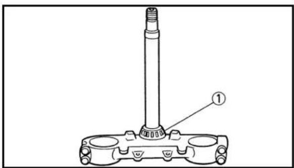
text_image
Technical diagram of a mechanical component with labeled part 1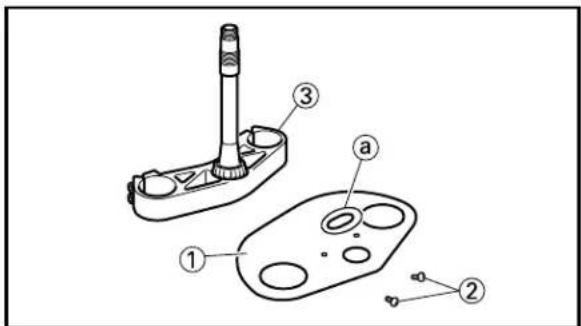
text_image
Technical diagram of a handheld device with labeled parts including a lever, handle, and control panel
text_image
Technical diagram showing a hand adjusting a mechanical component with labeled parts ① and ②, and a tool labeled B pointing to the component.EC564101
Bearing and ball race
-
Wash the bearings and ball races with a solvent.
-
Inspect:
-
Bearing ①
- Ball race
Pitting/Damage → Replace bearings and ball races as a set.
Install the bearing in the ball races. Spin the bearings by hand. If the bearings hang up or are not smooth in their operation in the ball races, replace bearings and ball races as a set.
EC564300
Steering damper
- Inspect:
- Steering damper ①
Bend/Damage → Replace.
Oil leaks/Unsmooth movement → Replace.
EC565000
ASSEMBLY AND INSTALLATION
EC565190
Under bracket
- Install:
- Bearing (lower) ①
NOTE:
Apply the lithium soap base grease on the dust seal lip and bearing inner circumference.
-
Install:
-
Inner fender ①
- Screw (inner fender) ②
To under bracket ③.
NOTE:
Install the inner fender with its brake hose through hole ⓐ facing to the right.
-
Install:
-
Ball race
- Bearing ①
- Ball race cover ②
NOTE:
Apply the lithium soap base grease on the bearing.
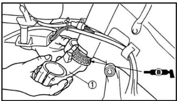
text_image
Technical diagram showing mechanical assembly with labeled parts and a tool labeled B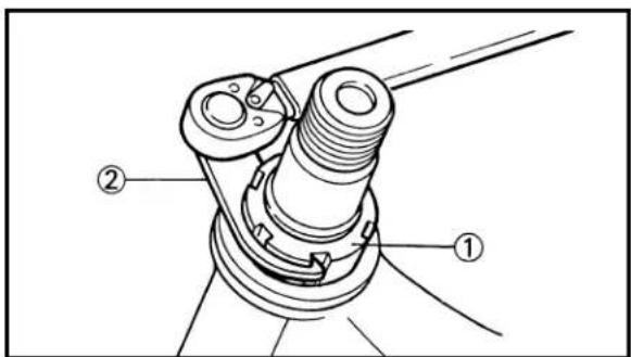
text_image
Technical diagram of a mechanical assembly with labeled parts ① and ②
natural_image
Mechanical assembly diagram showing two hands operating a valve with rotating components (no text or labels)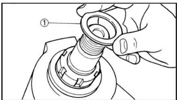
natural_image
Technical illustration of a hand adjusting a threaded mechanical component (no text or symbols present)
text_image
Technical diagram of an engine assembly with numbered parts for identification- Install:
- Under bracket ①
NOTE:
Apply the lithium soap base grease on the bearing.
- Install:
- Ring nut ① Tighten the ring nut using the ring nut wrench ②.
Refer to "STEERING HEAD INSPECTION AND ADJUSTMENT" section in the CHAPTER 3.
-
Check the steering shaft by turning it lock to lock. If there is any binding, remove the steering shaft assembly and inspect the steering bearings.
-
Install:
- Plain washer ①
-
Install:
-
Front fork ①
- Steering damper stay ② (right side only)
- Handlebar ③
- Handle crown ④
NOTE:
• Temporarily tighten the pinch bolts (under bracket).
- Do not tighten the pinch bolts (handle crown, steering damper stay and handlebar) yet.
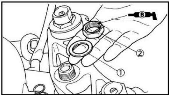
text_image
Technical diagram showing mechanical assembly with labeled parts ①, ②, and B
natural_image
Mechanical assembly diagram showing hands operating a bracket with a directional arrow indicating motion (no text or symbols present)
text_image
a ① ② ③9. Install:
- Plain washer ①
- Steering shaft nut ②
80 Nm (8.0 m·kg, 58 ft·lb)
NOTE:
Apply the lithium soap base grease on the steering shaft nut thread.
- After tightening the nut, check the steering for smooth movement. If not, adjust the steering by loosening the ring nut little by little.
11. Install:
• Steering damper bracket ①
- Pinch bolt (steering damper bracket) ②
5 Nm (0.5 m·kg, 3.6 ft·lb)
To steering damper ③.
NOTE:
When installing the steering damper bracket, provide a distance ⓐ of 9 mm (0.35 in) from its edge.
CAUTION:
Tighten the pinch bolt to specified torque. If torqued too much, it may cause the steering damper to malfunction.

text_image
Technical diagram showing mechanical assembly steps with numbered components and a close-up of the component being handled.12. Install:
- Pin ①
- Plain washer ②
- Steering damper ③
- Clip ④
- Bolt (steering damper) ⑤
23 Nm (2.3 m·kg, 17 ft·lb)
STEERING

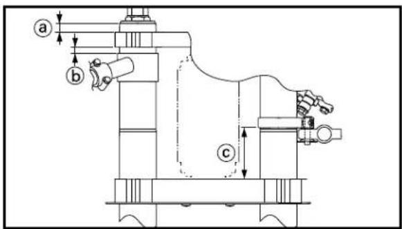
text_image
a b c13.Adjust:
- Front fork top end ⓐ
- Handlebar position ⑥
- Steering damper stay position © (right side only)

Front fork top end:
13 mm (0.51 in)
Handlebar position:
9 mm (0.35 in)
Steering damper stay position:
73 mm (2.87 in)
Refer to "FRONT FORK TOP END ADJUSTMENT" in the CHAPTER 3.

text_image
Technical diagram showing mechanical assembly with numbered components and labeled parts14. Tighten:
- Pinch bolt (handle crown) ①
20 Nm (2.0 m·kg, 14 ft·lb) - Pinch bolt (under bracket) ②
23 Nm (2.3 m·kg, 17 ft·lb) - Pinch bolt (handlebar) ③
7 Nm (0.7 m·kg, 5.1 ft·lb) - Pinch bolt (steering damper stay) ④ (right side only) 10 Nm (1.0 m·kg, 7.2 ft·lb) Refer to “FRONT FORK TOP END ADJUSTMENT” in the CHAPTER 3.

natural_image
Technical line drawing of a mechanical assembly with rotating components (no text or symbols)15.Check:
• Steering smooth action
Turn the handlebar to make sure no parts are being contacted with others.
Contact → Repair.
EC570000
SWINGARM
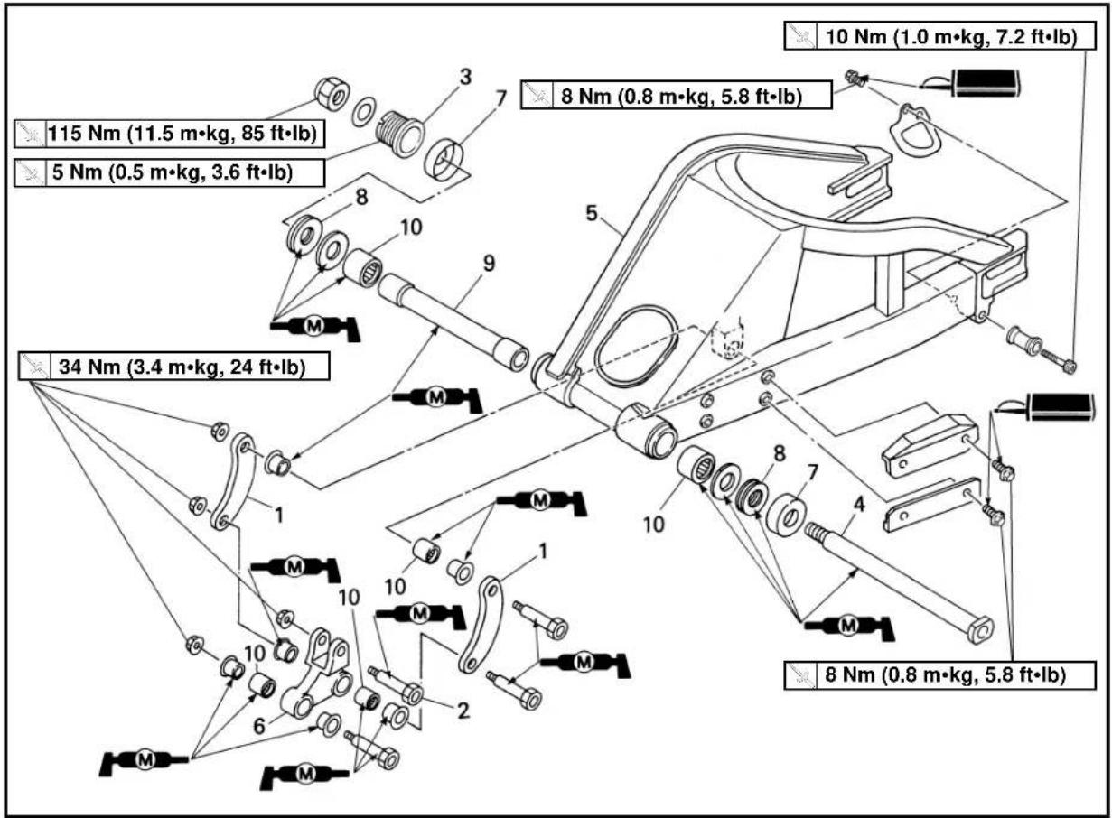
text_image
10 Nm (1.0 m·kg, 7.2 ft·lb) 8 Nm (0.8 m·kg, 5.8 ft·lb) 115 Nm (11.5 m·kg, 85 ft·lb) 5 Nm (0.5 m·kg, 3.6 ft·lb) 34 Nm (3.4 m·kg, 24 ft·lb) 8 Nm (0.8 m·kg, 5.8 ft·lb)Extend of removal: ① Swingarm removal ② Swingarm disassembly
| Extend of removal Order Part | name Q'ty Remarks | |||
| Preparation for Hold the machine by placingremoval the suitable stand. | SWINGARM REMOVALLower cowl and fuel tank Refer to "COWLING, INDUCTIONGUIDE, SEAT AND FUEL TANK" section in the CHAPTER 4.Exhaust pipe Refer to "EXHAUST PIPE AND SILENCER" section.Brake hose holderDrive chainRear wheel | ⚠WARNINGSupport the machine securely so there is no danger of it falling over. | ||
 | 12345678910 | Connecting rodBolt (rear shock absorber– relay arm)Pivot shaft adjust boltPivot shaftSwingarmRelay armCoverThrust bearingBushBearing | 211112215 | Hold the swingarm.Use special tool.Refer to "REMOVAL POINTS".Refer to "REMOVAL POINTS". |
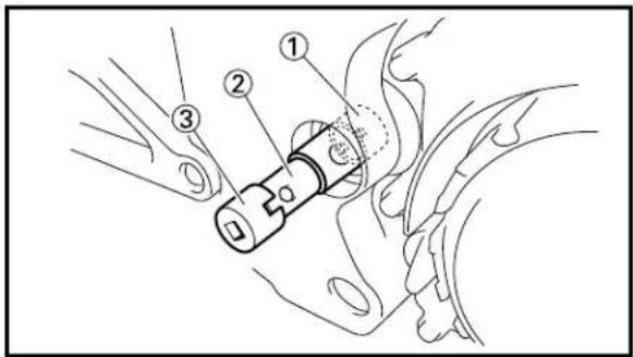
text_image
Technical diagram showing labeled mechanical components with numbered parts, likely illustrating a valve or connector assembly.
text_image
Technical diagram of a mechanical assembly with numbered components, likely for assembly or maintenance instructions.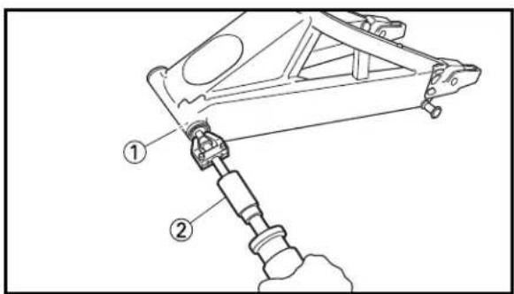
text_image
Technical diagram of a mechanical assembly with labeled parts ① and ②
text_image
Technical diagram of a mechanical assembly with labeled parts ① and ②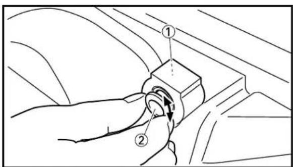
text_image
Technical diagram showing a hand holding a mechanical component with labeled parts ① and ②EC573000
REMOVAL POINTS
EC573153
Swingarm
- Loosen:
- Pivot shaft adjust bolt ①
NOTE:
Loosen the pivot shaft adjust bolt using the pivot shaft wrench ② and pivot shaft wrench adapter ③.

Pivot shaft wrench:
YM-1455/90890-01455
Pivot shaft wrench adapter:
YM-1476/90890-01476
-
Remove:
-
Pivot shaft ①
- Swingarm ②
EC573210
Bearing
- Remove:
- Bearing ①
Use a general bearing puller ②.
EC574010
INSPECTION
Wash the bearings, bushes, collars, and covers in a solvent.
EC574131
Swingarm
-
Inspect:
-
Bearing ①
- Bush ②
Free play exists/Unsmooth revolution/Rust
→ Replace bearing and bush as a set.
-
Inspect:
-
Bearing ①
- Collar ②
Free play exists/Unsmooth revolution/Rust
→ Replace bearing and collar as a set.

text_image
Technical diagram of a mechanical component with numbered parts labeled ① and ②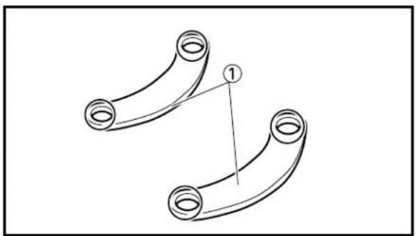
natural_image
Diagram of two curved mechanical components with circular ends, connected by lines and a numbered label (1) pointing to one component.
natural_image
Diagram of two cylindrical objects with directional arrows indicating length (no text or symbols)
text_image
Technical diagram showing a mechanical component with labeled parts (b) and (c), including circular features and directional arrows.
text_image
dEC574220
Relay arm
1. Inspect:
- Bearing ①
• Collar ②
Free play exists/Unsmooth revolution/Rust
→ Replace bearing and collar as a set.
EC574320
Connecting rod
1. Inspect:
- Connecting rod ①
Wear/Damage → Replace.
EC574520
Swingarm side clearance
1. Measure:
- Bush length ⓐ
2. Measure:
- Thrust bearing (right) thickness ⓑ
- Thrust bearing (left) thickness ©
3. Measure:
- Swingarm head pipe length ⓓ
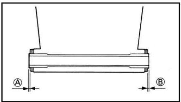
text_image
A B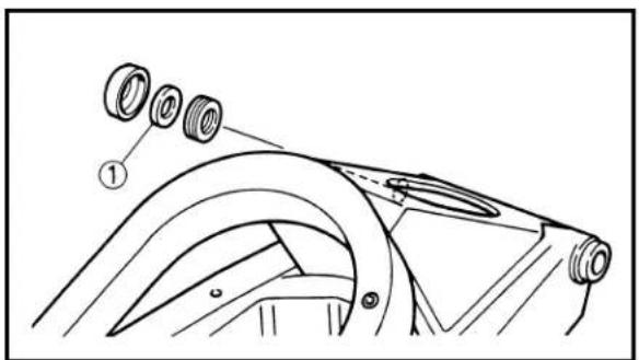
text_image
Technical diagram showing mechanical assembly with labeled parts and numbered annotation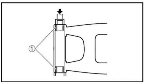
text_image
Technical diagram showing a mechanical assembly with labeled component ① and directional arrow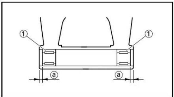
text_image
① ① a a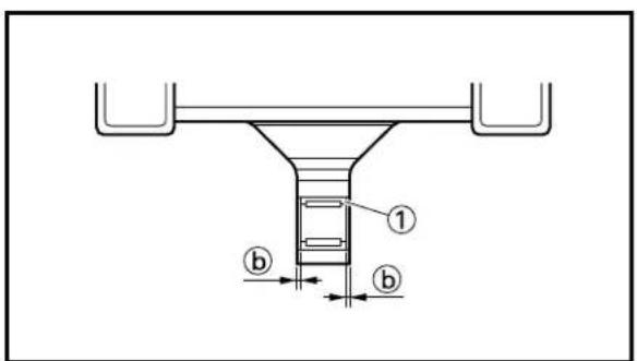
text_image
① b b4. Calculate:
- Swingarm side clearance “ ^A + ^B ” Out of specification → Adjust side clearance using shim. By using formula given below.
$$ \text { “ } \textcircled {A} + \textcircled {B} = \textcircled {a} - (\textcircled {b} + \textcircled {c} + \textcircled {d}) $$

Side clearance “Ⓐ + Ⓑ”: 0.05\~0.35 mm (0.002\~0.014 in)
If the side clearance is out of specification, adjust it to specification by installing the adjust shim ① at position, ④ and ⑧.
NOTE:
- The adjust shim is available only in the 0.3 mm (0.012 in)-thick type. - When only one shim is required, install it on the left side, and when two shims are necessary, install them on both right and left sides.
EC575000
ASSEMBLY AND INSTALLATION
EC575300
Bearing
- Install:
- Bearing ① To swingarm.
NOTE:
- Apply the lithium soap base grease on the bearing when installing. - Install the bearing by pressing it on the side having the manufacture's marks or numbers.

Installed depth of bearings:
For head pipe ⓐ: 1.0 mm (0.04 in) For connecting rod bracket ⓑ: 0.5 mm (0.02 in)

text_image
a a ① a a2. Install:
- Bearing ①
To relay arm.
NOTE:
- Apply the lithium soap base grease on the bearing when installing.
- Install the bearing by pressing it on the side having the manufacture's marks or numbers.

Installed depth of bearings ⓐ: Zero mm (Zero in)

text_image
Technical diagram of a mechanical linkage system with labeled components and connection pointsEC575142
Swingarm
- Install:
- Collar ①
To relay arm ②.
NOTE:
Apply the molybdenum disulfide grease on the collars and bearings.
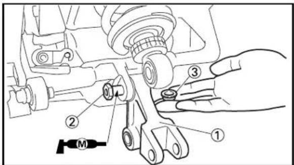
text_image
Technical diagram showing mechanical assembly with numbered components and a labeled motor (M)-
Install:
-
Relay arm ①
- Bolt (relay arm) ②
- Nut (relay arm) ③
34 Nm (3.4 m·kg, 24 ft·lb)
NOTE:
Apply the molybdenum disulfide grease on the bolt.
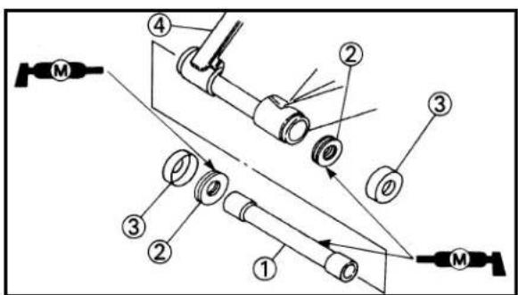
text_image
Technical diagram of a mechanical assembly with numbered components and labeled parts (M)-
Install:
-
Bush ①
- Thrust bearing ②
- Cover ③
To swingarm ④.
NOTE:
Apply the molybdenum disulfide grease on the bush, bearings and cover lips.
SWINGARM


text_image
Technical diagram of a mechanical assembly with numbered components and a labeled reference marker 'M'
text_image
Technical diagram showing a mechanical assembly with numbered components, likely illustrating a valve or connector mechanism.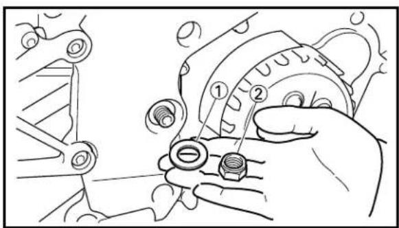
text_image
Technical diagram showing mechanical assembly with numbered parts and tool path
text_image
Technical diagram showing mechanical assembly with labeled parts and directional arrows indicating motion or force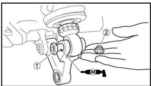
text_image
Technical diagram showing mechanical assembly with labeled parts and a motor indicator4. Install:
- Swingarm ①
- Pivot shaft ②
NOTE:
- Apply the molybdenum disulfide grease on the pivot shaft.
- Insert the pivot shaft from left side.
5. Tighten:
- Pivot adjust bolt ①
5 Nm (0.5 m·kg, 3.6 ft·lb)
NOTE:
Use the pivot shaft wrench ② and pivot shaft wrench adapter ③ to tighten the pivot adjust bolt.

Pivot shaft wrench:
YM-1455/90890-01455
Pivot shaft wrench adapter:
YM-1476/90890-01476
6. Install:
- Plain washer ①
- Nut (pivot shaft) ②
115 Nm (11.5 m·kg, 85 ft·lb)
7. Check:
- Swingarm side play ⓐ Free play exists → Check side clearance.
- Swingarm up and down movement ⑥ Unsmooth movement/Binding/Rough spots → Grease or replace bearings, bushes and collars.
8. Install:
- Bolt (rear shock absorber – relay arm) ①
- Nut (rear shock absorber – relay arm) ②
34 Nm (3.4 m·kg, 24 ft·lb
NOTE:
Apply the molybdenum disulfide grease on the bolt.
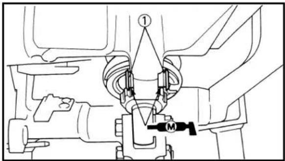
text_image
Technical diagram of a mechanical assembly with labeled components and connection points
text_image
Technical diagram of a mechanical assembly with labeled parts and numbered annotations- Install:
- Collar (swingarm) ①
NOTE:
Apply the molybdenum disulfide grease on the collars and bearings.
-
Install:
-
Connecting rod ①
- Bolt (connecting rod) ②
- Nut (connecting rod) ③
34 Nm (3.4 m·kg, 24 ft·lb)
NOTE:
- Install the connecting rods with the mark ⓐ outward of the chassis.
- Apply the molybdenum disulfide grease on the bolts.
EC580000
REAR SHOCK ABSORBER
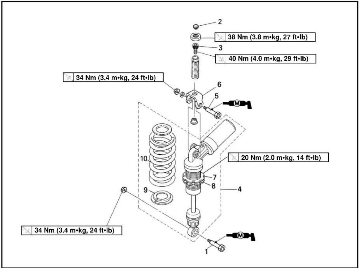
text_image
38 Nm (3.8 m·kg, 27 ft·lb) 40 Nm (4.0 m·kg, 29 ft·lb) 34 Nm (3.4 m·kg, 24 ft·lb) 20 Nm (2.0 m·kg, 14 ft·lb) 34 Nm (3.4 m·kg, 24 ft·lb)Extend of removal: ① Rear shock absorber removal ② Rear shock absorber disassembly
| Extend of removal Order Part | name Q'ty Remarks | |||
| Preparation for Hold the machine by placingremoval the suitable stand. | REAR SHOCK ABSORBER REMOVALLower cowl, seat and fuel tankExhaust pipe Refer to “EXHAUST PIPE | Refer to “COWLING, INDUCTION GUIDE SEAT AND FUEL TANK” section in the CHAPTER 4.AND SILENCER” section in the CHAPTER 4. | ||
 | 1 Bolt (rear shock absorber – relay arm)2 Cap3 Bolt (Upper bracket)4 Rear shock absorber5 Bolt (rea shock absorber – upper bracket)6 Upper bracket7 Locknut8 Adjuster9 Spring guide10 Spring (rear shock absorber) | Hold the swingarm.Refer to “REMOVAL POINTS”.Loosen.Loosen.1 | ||
EC586000
HANDLING NOTE
WARNING
This shock absorber is provided with a separate type tank filled with high-pressure nitrogen gas. To prevent the danger of explosion, read and understand the following information before handling the shock absorber.
The manufacturer can not be held responsible for property damage or personal injury that may result from improper handling.
- Never tamper or attempt to disassemble the cylinder or the tank.
- Never throw the shock absorber into an open flame or other high heat. The shock absorber may explode as a result of nitrogen gas expansion and/or damage to the hose.
- Be careful not to damage any part of the gas tank. A damaged gas tank will impair the damping performance or cause a malfunction.
- Take care not to scratch the contact surface of the piston rod with the cylinder; or oil could leak out.
- Never attempt to remove the plug at the bottom of the nitrogen gas tank. It is very dangerous to remove the plug.
- When scrapping the shock absorber, follow the instructions on disposal.
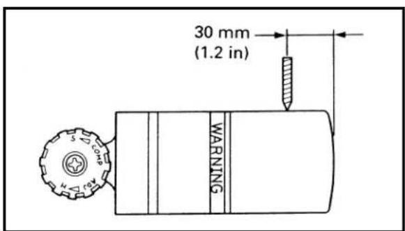
text_image
30 mm (1.2 in) WARNINGEC587011
NOTES ON DISPOSAL (YAMAHA DEALERS ONLY)
Before disposing of the shock absorber, be sure to extract the nitrogen gas. To do so, drill a 2 or 3 mm (0.08\~0.12 in) hole through the tank at a position 30 mm (1.2 in) from the bottom end of the tank. At this time, wear eye protection to prevent eye damage from escaping gas and/or metal chips.
WARNING
To dispose of a damaged or worn-out shock absorber, take the unit to your Yamaha dealer for this disposal procedure.

natural_image
Line drawing of a hand adjusting a car's spring system (no text or symbols)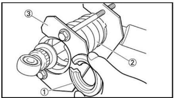
text_image
Technical diagram of a mechanical assembly with numbered components labeled ①, ②, and ③.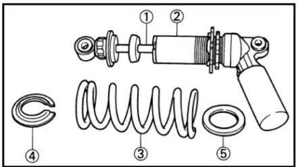
text_image
Technical diagram of a mechanical assembly with numbered components for identificationEC583000
REMOVAL POINTS
EC583160
Rear shock absorber
- Remove:
- Rear shock absorber ①
NOTE:
Remove the rear shock absorber between the rear frame and swingarm.
EC583221
Spring (rear shock absorber)
- Remove:
- Spring guide ①
•Spring ②
NOTE:
Remove the spring guide while compressing the spring by using the spring compressor ③.
EC584000
INSPECTION
EC584130
Rear shock absorber
- Inspect:
- Damper rod ① Bends/Damage → Replace absorber assembly.
- Shock absorber ② Oil leaks → Replace absorber assembly. Gas leaks → Replace absorber assembly.
- Spring ③ Damage → Replace spring. Fatigue → Replace spring. Move spring up and down.
- Spring guide ④ Wear/Damage → Replace spring guide.
- Plate ⑤ Wear/Damage → Replace plate.
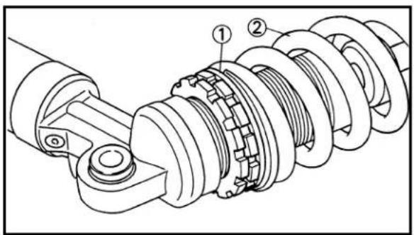
text_image
Technical diagram of a mechanical assembly with numbered components, likely illustrating a gear or worm mechanism.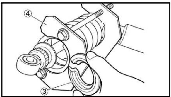
text_image
Technical diagram of a mechanical assembly with numbered parts labeled ③ and ④
natural_image
Technical line drawing of a mechanical assembly with coiled spring and housing (no text or symbols)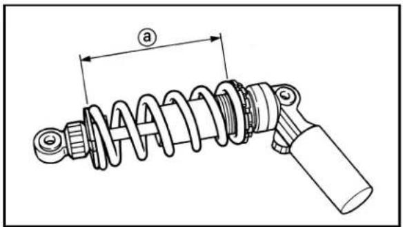
text_image
aEC585000
ASSEMBLY AND INSTALLATION
EC585143
Spring (rear shock absorber)
-
Install:
-
Plate ①
- Spring ②
- Spring guide ③
NOTE:
Install the spring guide while compressing the spring by using the spring compressor ④.
- Tighten:
- Adjuster ①
- Adjust:
- Spring length (installed) ⓐ
| Spring length (installed) ⓐ: | ||
| Standard length | Extent of adjustment | |
| 137 mm (5.39 in) | 133~142 mm(5.24~5.59 in) | |
NOTE:
The length of the spring (installed) changes 1.5 mm (0.06 in) per turn of the adjuster.
CAUTION:
Never attempt to turn the adjuster beyond the maximum or minimum setting.
REAR SHOCK ABSORBER


natural_image
Technical line drawing of a mechanical assembly with helical components and gears (no text or symbols)
text_image
Technical diagram of a mechanical assembly with numbered components and a labeled component M4. Tighten:
- Locknut ①
20 Nm (2.0 m·kg, 14 ft·lb)
EC5852A1
Rear shock absorber
1. Install:
- Upper bracket ①
- Bolt (rear shock absorber – upper bracket) ②
- Plain washer (rear shock absorber – upper bracket) ③
- Nut (rear shock absorber – upper bracket) ④
34 Nm (3.4 m·kg, 24 ft·lb)
NOTE:
Apply the molybdenum disulfide grease on the bolt.
2. Install:
- Rear shock absorber
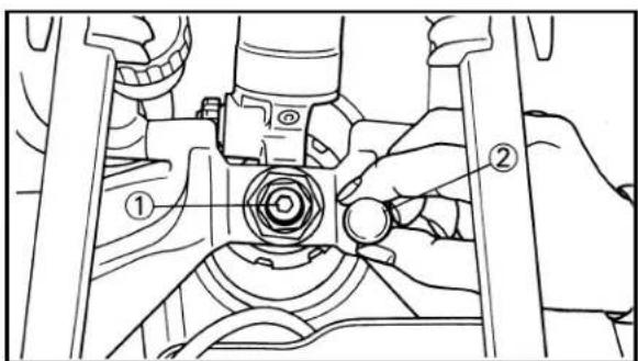
text_image
Technical diagram showing mechanical assembly with labeled parts, including numbered annotations ① and ②
text_image
Technical diagram of a mechanical assembly with labeled parts and a tool labeled 'M'3. Install:
- Bolt (upper bracket) ①
40 Nm (4.0 m·kg, 29 ft·lb)
- Cap ②
4. Install:
- Bolt (rear shock absorber – relay arm) ①
- Nut (rear shock absorber – relay arm) ②
34 Nm (3.4 m·kg, 24 ft·lb)
NOTE:
Apply the molybdenum disulfide grease on the bolt.
EC600000
ELECTRICAL
EC610000
ELECTRICAL COMPONENTS AND WIRING DIAGRAM
EC611000
ELECTRICAL COMPONENTS
① CDI unit
⑨ Fuel pump relay
② Voltage regulator
⑩ Fuel pump stop switch
③ Tachometer assembly
⑪ Battery
④ Fuse
⑫ CDI magneto
⑤ Main switch
⑬ Spark pulg
⑥ Ignition coil
⑭ Thermo unit
⑦ Solenoid valve
⑮ Servomotor
⑧ Fuel pump
COLOR CODE
B .....Black
B/L .....Black/Blue
Br.....Brown
B/R .....Black/Red
G ....Green
B/W ....Black/White
Gy .....Gray
G/W ....Green/White
O .....Orange
W/B ....White/Black
P .....Pink
W/G ....White/Green
R ....Red
W/L ....White/Blue
Y ..... Yellow
W/R ....White/Red
W ..... White
Y/L .....Yellow/Blue
B/Br ....Black/Brown

text_image
Labeled technical diagram of a motorcycle with numbered parts for identificationEC612000
WIRING DIAGRAM
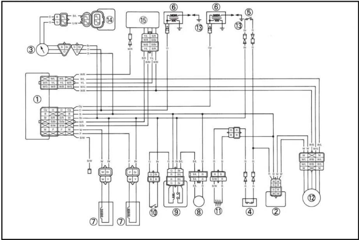
flowchart
graph TD
    A["①"] --> B["②"]
    B --> C["③"]
    C --> D["④"]
    D --> E["⑤"]
    E --> F["⑥"]
    F --> G["⑦"]
    G --> H["⑧"]
    H --> I["⑨"]
    I --> J["⑩"]
    J --> K["⑪"]
    K --> L["⑫"]
    L --> M["⑬"]
    M --> N["⑭"]
    N --> O["⑮"]
    O --> P["⑯"]
    P --> Q["⑰"]
    Q --> R["⑱"]
    R --> S["⑲"]
    S --> T["⑳"]
    T --> U["⑪"]
    U --> V["⑫"]
    V --> W["⑬"]
    W --> X["⑭"]
    X --> Y["⑮"]
    Y --> Z["⑯"]
    Z --> AA["⑰"]
    AA --> AB["⑱"]
    AB --> AC["㉑"]
    AC --> AD["㉒"]
    AD --> AE["㉓"]
    AE --> AF["㉔"]
    AF --> AG["㉕"]
    AG --> AH["㉖"]
    AH --> AI["㉗"]
    AI --> AJ["㉘"]
    AJ --> AK["㉙"]
    AK --> AL["㉚"]
    AL --> AM["㉛"]
    AM --> AN["㉜"]
    AN --> AO["㉝"]
    AO --> AP["㉞"]
    AP --> AQ["㉟"]
    AQ --> AR["㉟"]
    AR --> AS["㉟c"]
    AS --> AT["㉟d"]
    AT --> AU["㉟e"]
    AU --> AV["㉟f"]
    AV --> AW["㉟g"]
    AW --> AX["㉟h"]
    AX --> AY["㉟i"]
    AY --> AZ["㉟j"]
    AZ --> BA["㉟k"]
    BA --> BB["㉟l"]
    BB --> BC["㉟m"]
    BC --> BD["㉟n"]
    BD --> BE["㉟o"]
    BE --> BF["㉟p"]
    BF --> BG["㉟q"]
    BG --> BH["㉟r"]
    BH --> BI["㉟t"]
    BI --> BJ["㉟u"]
    BJ --> BK["㉟v"]
    BK --> BL["㉟w"]
    BL --> BM["㉟x"]
    BM --> BN["㉟y"]
    BN --> BO["㉟z"]
EC620000
IGNITION SYSTEM
EC621031
INSPECTION STEPS
Use the following steps for checking the possibility of the malfunctioning engine being attributable to ignition system failure and for checking the spark plug which will not spark.

flowchart
graph TD
    A["Check fuse."] -->|OK| B["*1 Check battery Recharge or replace."]
    B -->|OK| C["Spark gap test"]
    C -->|No spark| D["Check spark plug cap. Replace."]
    D -->|OK| E["Check entire ignition system for connection."]
    E -->|OK| F["Check main switch."]
    F -->|OK| G["Check ignition coil."]
    G -->|OK| H["Check CDI magneto."]
    H -->|OK| I["Replace CDI unit."]

    B -->|No good| J["Replace fuse and check wireharness."]
    C -->|Spark| K["*2 Clean or replace spark plug."]
    D -->|No good| L["Repair or replace."]
    E -->|No good| M["Replace."]
    G --> N["Primary coil"] & O["Secondary coil"] & P["Pick-up coil"] & Q["Source coil"] & R["Replace."]
    N -->|No good| S["Replace."]
    O -->|No good| T["Replace."]
    P -->|No good| U["Replace."]
    Q -->|No good| V["Replace."]
    R --> W["Replace."]
*1 marked : Refer to "BATTERY INSPECTION" section in the CHAPTER 3.
*2 marked : Only when the ignition checker is used.
NOTE:
- Remove the following parts before inspection.
1) Cowling 3) Seat
2) Fuel tank
- Use the following special tools in this inspection.

Dynamic spark tester:
YM-34487
Ignition checker:
90890-06754

Pocket tester:
YU-3112-C/90890-03112
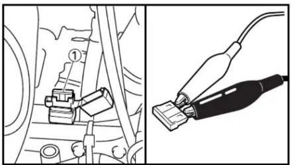
natural_image
Technical illustration showing a mechanical assembly with labeled components and a close-up of a plug (no text or symbols present)
text_image
A ① ③ ④
text_image
Technical diagram of a mechanical assembly with numbered components and labeled parts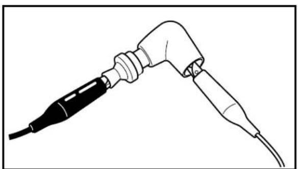
natural_image
Line drawing of a welding torch with a black connector and cable (no text or symbols)EC629000 FUSE INSPECTION
-
Remove: • Fuse ①
-
Check:
- Fuse conduct Use pocket tester (tester selector position × 1 ). Not continuous → Replace fuse and check that the wireharness is not shorted.
EC622020 SPARK GAP TEST
- Disconnect the fuel pump coupler to prevent the fuel pump operating.
- Disconnect the spark plug cap from spark plug.
- Connect the dynamic spark tester ① (ignition checker ②) as shown.
- Spark plug cap ③
- Spark plug ④
A For USA and CDN
B Except for USA and CDN - Start the engine and increase the spark gap until misfire occurs. (for USA and CDN)
- Move the main switch to "RUN" and rotate the rear wheel with gear in 3rd and check the spark gap. (except for USA and CDN)

Minimum spark gap: 5.0 mm(0.20 in)
EC623001 SPARK PLUG CAP INSPECTION
- Remove: • Spark plug cap
CAUTION:
Do not pull the spark plug lead out of the spark plug cap. Turn the spark plug cap counterclockwise to remove it and clockwise to install it.
2. Check:
- Spark plug cap resistance Out of specification → Replace.
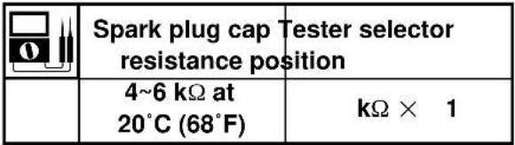 |
EC624000 COUPLERS AND LEADS CONNECTION INSPECTION
1. Check:
- Couplers and leads connection Rust/ Dust/ Looseness/Short-circuit → Repair or replace.
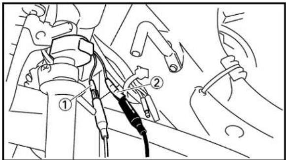
text_image
Technical diagram showing mechanical assembly with labeled parts, including numbered annotations ① and ②EC62A000 MAIN SWITCH INSPECTION
1. Inspect:
- Main switch conduct
| Tester (+) lead → | Red lead 1 |
| Tester (-) lead → | Brown lead 2 |
| R Br Tester selector position | ||||
| RUN | ○—○ | Ω×1 | ||
| OFF | ||||
Continuous while the main switch is moved to "OFF" → Replace.
Not continuous while the main switch is moved to "RUN" → Replace.
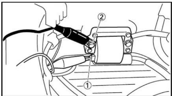
text_image
Technical diagram showing a car's electrical testing setup with labeled components ① and ②EC626002 IGNITION COIL INSPECTION
1. Inspect:
- Primary coil resistance Out of specification → Replace.
| Tester (+) lead → | Orange (Gray) lead 1 |
| Tester (−) lead → | Black lead 2 |
| Primary coil Tester selector resistance position | ||
| 0.14~0.18 Ω at 20°C (68°F) | Ω × 1 | |
IGNITION SYSTEM
ELEC


text_image
Technical diagram showing car suspension system with labeled components and wiring connections2. Inspect:
- Secondary coil resistance Out of specification → Replace.
| Tester (+) lead → | Spark plug lead 1 |
| Tester (−) lead → | Orange (Gray) lead 2 |
| Secondary coil resistance position | Tester selector | |
| 5.0~7.4 kΩ at 20°C (68°F) | kΩ × 1 |
NOTE:
When inspecting the secondary coil resistance, remove the spark plug cap.

text_image
Technical diagram showing mechanical assembly with labeled parts and a numbered inset showing W/L, W/B, W/G, W, W/C symbols.EC627031
CDI MAGNETO INSPECTION
1. Inspect:
- Pick-up coil resistance (left cylinder) Out of specification → Replace.
| Tester (+) lead → | White/Blue lead 1 |
| Tester (-) lead → | White/Black lead 2 |
| Pick-up coil Tester selector resistance position | ||
| 94~140 Ω at 20°C (68°F) | Ω × 100 | |

text_image
Technical diagram showing mechanical assembly with labeled parts and a numbered inset showing a control panel layout.2. Inspect:
- Pick-up coil resistance (right cylinder) Out of specification → Replace.
| Tester (+) lead → | White/Green lead 1 |
| Tester (-) lead → | White/Black lead 2 |
| Pick-up coil Tester selector resistance position | ||
| 94~140 Ω at 20°C (68°F) | Ω × 100 | |
IGNITION SYSTEM
ELEC

text_image
W/L W/B W/G ① ② ① ②3. Inspect:
- Source coil resistance Out of specification → Replace.
| Tester (+) lead → | White lead 1 |
| Tester (-) lead → | White lead 2 |
| Source coil Tester selector resistance position | ||
| 2.3~3.5 Ω at 20°C (68°F) | Ω × 1 | |
EC628000
CDI UNIT INSPECTION
Check all electrical components. If no fault is found, replace the CDI unit. Then check the electrical components again.
EC680000
CHARGING SYSTEM
EC681001
INSPECTION STEPS
If the battery is not charged, use the following inspection steps.

flowchart
graph TD
    A["*1 Check fuse."] -->|OK| B["*2 Check battery Recharge or replace."]
    B -->|OK| C["Check each coupler and wire connection."]
    C -->|OK| D["Check charging voltage."]
    D -->|No good| E["*1 Check CDI magneto."]
    E -->|OK| F["Check voltage regulator. Replace."]
    F -->|No good| G["Source coil"]
    G -->|No good| H["Charging system is good."]
    H -->|No good| I["Repair or replace."]
    I -->|No good| J["Replace fuse and check wireharness."]
    J -->|No good| K["End"]
*1 marked : Refer to "IGNITION SYSTEM" section.
*2 marked : Refer to "BATTERY INSPECTION" section in the CHAPTER 3.
NOTE:
- Remove the following parts before inspection.
1) Cowling
2) Fuel tank - Use the following special tool in this inspection.

Pocket tester: YU-3112-C/90890-03112
EC624000 COUPLERS AND LEADS CONNECTION INSPECTION
1. Check:
- Couplers and leads connection Rust/ Dust/ Looseness/Short-circuit → Repair or replace.
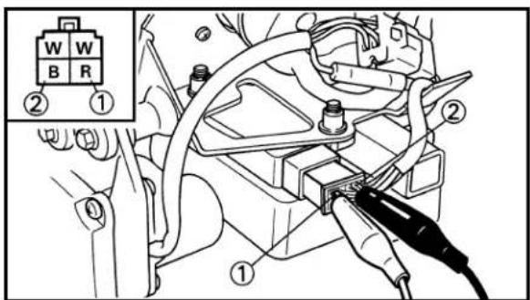
text_image
W W B R ② ① ①EC682000 CHARGING VOLTAGE INSPECTION
-
Start the engine.
-
Inspect:
- Charging voltage Out of specification → If no failure is found in checking the source coil resistance, check the voltage regulator.
| Tester (+) lead → | Red lead 1 |
| Tester (-) lead → | Black lead 2 |
| Charging Tester selector voltage position | ||
| 14.2~15.2 V at 5,000 r/min | DCV-20 | |
text_image
① w1 w2 B R ④ ③ ①EC683000 VOLTAGE REGULATOR INSPECTION
- Check:
- Voltage regulator conduct Use pocket tester (tester selection position × 1 ).
| Tester (+)lead(-) lead | W1 W2 R B | |||||
| 1 | 2 | 3 | 4 | |||
| W1 1 | × | ○ | × | |||
| W2 2 | × | ○ × | ||||
| R 3 | × | × | × | |||
| B 4 | ○ | ○ | ○ | |||
“○” indicates continuity and “×” non-continuity.
In case of continuity for “×” → Replace. In case of non-continuity for “○” → Replace.
NOTE:
If nothing is wrong with the continuity of the voltage regulator and with all the others in the charging system, replace the voltage regulator.
EC640000
YPVS SYSTEM
EC641021
INSPECTION STEPS
If the servomotor will not turn, use the following inspection steps.
flowchart
graph TD
    A["*1 Check fuse."] -->|OK| B["*2 Check battery Recharge or replace."]
    B -->|OK| C["Check each coupler and wire connection."]
    C -->|OK| D["*1 Check main switch. Replace."]
    D -->|OK| E["Check servomotor operation."]
    E -->|No good| F["Check servomotor"]
    F -->|No good| G["Replace."]
    F -->|OK| H["Replace CDI unit."]
    A -->|No good| I["Replace fuse and check wireharness."]
    B -->|No good| J["Repair or replace."]
    C -->|No good| K["No good"]
    D -->|No good| L["No good"]
    E -->|No good| M["No good"]
*1 marked : Refer to "IGNITION SYSTEM" section.
*2 marked : Refer to "BATTERY INSPECTION" section in the CHAPTER 3.
NOTE:
- Remove the following parts before inspection.
1) Cowling
2) Fuel tank
- Use 12V battery in this inspection.
- Use the following special tool in this inspection.

Pocket tester: YU-3112-C/90890-03112
EC624000 COUPLERS AND LEADS CONNECTION INSPECTION
1. Check:
- Couplers and leads connection Rust/ Dust/ Looseness/Short-circuit → Repair or replace.

natural_image
Technical line drawing of a mechanical assembly with no visible text or symbols
text_image
Y/L B/R W/B B/Br ① ②
natural_image
Technical line drawing of a mechanical assembly with hands operating a tool (no text or symbols visible)EC642020
-
Disconnect the fuel pump coupler to prevent the fuel pump operating.
-
Inspect:
- Servomotor ① Operative when the main switch is moved to "RUN" → OK
EC643001
SERVOMOTOR INSPECTION
- Disconnect the YPVS cable from the servo-motor.
- Disconnect the servomotor lead.
- Connect 12V battery to the servomotor lead.
Battery (+) lead → Black/Red lead ① Battery (-) lead → Black/Brown lead ②
- Inspect:
- Servomotor ① Not operate → Replace servomotor.
EC650001
SOLENOID VALVE SYSTEM
EC651021
INSPECTION STEPS
If the solenoid valve will not operate, use the following inspection steps.

flowchart
graph TD
    A["*1 Check fuse."] -->|OK| B["*2 Check battery Recharge or replace."]
    B -->|OK| C["Check each coupler and wire connection."]
    C -->|OK| D["*1 Check main switch. Replace."]
    D -->|OK| E["Check solenoid valve operation."]
    E -->|No good| F["Check solenoid valve coil."]
    F -->|No good| G["Replace CDI unit."]
    F -->|No good| H["Replace fuse and check wireharness."]
    F -->|No good| I["Repair or replace."]
    F -->|No good| J["Replace."]
*1 marked : Refer to "IGNITION SYSTEM" section.
*2 marked : Refer to "BATTERY INSPECTION" section in the CHAPTER 3.
NOTE:
- Remove the following parts before inspection.
1) Cowling 4) Induction guide (right cylinder)
2) Fuel tank 5) Seat
3) Induction cap (left cylinder)
- Use I2V battery in this inspection.
- Use the following special tools in this inspection.

Pocket tester: YU-3112-C/90890-03112
EC624000 COUPLERS AND LEADS CONNECTION INSPECTION
1. Check:
- Couplers and leads connection Rust/ Dust/ Looseness/Short-circuit → Repair or replace.

text_image
Technical diagram of a mechanical assembly with labeled component ①EC652020
-
Disconnect the fuel pump and servomotor coupler to prevent the fuel pump and servomotor operating.
-
Inspect:
- Solenoid valve ① Click when the main switch is moved to "RUN" → OK
NOTE:
Before checking the solenoid valve, disconnect the other solenoid valve lead.

text_image
Technical diagram showing mechanical assembly with labeled parts and a zoomed-in view of component positioningEC653002
SOLENOID VALVE COIL INSPECTION
- Inspect:
- Solenoid valve coil resistance Out of specification → Replace.
| Tester (+) lead → | Yellow lead 1 |
| Tester (−) lead → | White lead 2 |
 | Solenoid Tester selector resistance position | |
| 52.0~63.6 Ω at 20°C (68°F) | Ω × 10 | |
EC6A0000
THERMO UNIT SYSTEM
EC6A1011
INSPECTION STEPS
If the water temperature gauge (thermo unit) will not operate, use the following inspection steps.

flowchart
graph TD
    A["*1 Check fuse."] -->|OK| B["*2 Check battery Recharge or replace."]
    B -->|OK| C["Check each coupler and wire connection."]
    C -->|OK| D["*1 Check main switch. Replace."]
    D -->|OK| E["Check thermo unit."]
    E -->|OK| F["Replace tachometer assembly."]
    A -->|No good| G["Replace fuse and check wireharness."]
    B -->|No good| H["Repair or replace."]
    C -->|No good| I["Replace."]
    D -->|No good| J["Replace."]
*1 marked : Refer to "IGNITION SYSTEM" section.
*2 marked : Refer to "BATTERY INSPECTION" section in the CHAPTER 3.
NOTE:
- Remove the following parts before inspection.
1) Cowling - Use the following special tools in this inspection.

Pocket tester: YU-3112-C/90890-03112
EC624000 COUPLERS AND LEADS CONNECTION INSPECTION
1. Check:
- Couplers and leads connection Rust/ Dust/ Looseness/Short-circuit → Repair or replace.

natural_image
Technical line drawing of a mechanical assembly with hoses and components (no text or symbols)
text_image
Diagram of a liquid pressure measurement setup with labeled components and a multimeter connected to a beaker.EC6A2000
THERMO UNIT INSPECTION
- Drain the cooling water.
- Remove:
-
Thermo unit ①
-
Immerse the thermo unit with a tester lead connected in a container containing cooling (tap) water ① down to the upper threaded portion ②.
② Water temperature gauge
③ Poket tester
- Inspect:
- Thermo unit resistance Measure the resistance while gradually heating the cooling water. Out of specification → Replace.
| Cooling Thermo Tester water unit temperature | selector resistance position | ||
| 50°C (122°F) | 9.72~11.4 kΩ | kΩ × 1 | |
| 80°C (176°F) | 3.41~4.01 kΩ |
NOTE:
Do not allow the thermo unit to contact the test container bottom.
EC670000
FUEL PUMP SYSTEM
EC671001
INSPECTION STEPS
If the fuel pump will not operate, use the following inspection steps.

flowchart
graph TD
    A["*1 Check fuse."] -->|OK| B["*2 Check battery Recharge or replace."]
    B -->|OK| C["Check each coupler and wire connection."]
    C -->|OK| D["*1 Check main switch. Replace."]
    D -->|OK| E["Check fuel pump stop switch."]
    E -->|OK| F["Check fuel pump relay."]
    F -->|OK| G["Check fuel pump operation."]
    G -->|No good| H["Fuel pump coil"]
    H -->|OK| I["Check fuel pump."]
    I -->|No good| J["Replace."]
    H -->|No good| K["Replace fuse and check wireharness."]
    K --> L["Repair or replace."]
    H -->|No good| M["Replace."]
    M --> N["Replace."]
*1 marked : Refer to "IGNITION SYSTEM" section.
*2 marked : Refer to "BATTERY INSPECTION" section in the CHAPTER 3.
NOTE:
- Remove the following parts before inspection.
1) Cowling 3) Seat
2) Fuel tank 4) Induction cap (left cylinder)
- Use 12V battery in this inspection.
- Use the following special tool in this inspection.

Pocket tester: YU-3112-C/90890-03112
EC624000 COUPLERS AND LEADS CONNECTION INSPECTION
1. Check:
- Couplers and leads connection Rust/ Dust/ Looseness/Short-circuit → Repair or replace.
text_image
UPPER ①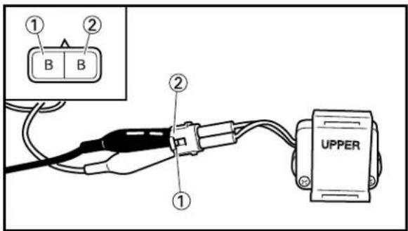
text_image
Technical diagram of a vehicle seatbelt assembly with labeled component 1EC672000 FUEL PUMP STOP SWITCH INSPECTION
1. Remove:
- Fuel pump stop switch ①
2. Inspect:
- Fuel pump stop switch conduct To inspect, tilt the fuel pump stop switch to the right and left.
| Tester (+) lead → | Black lead 1 |
| Tester (-) lead → | Black lead 2 |
| B B1 | Tester selector2 position | ||
| Tilted 90° | ○—○ | ||
| Normal | |||
Continuous if normal → Replace. Not continuous if tilted 90^ → Replace.
EC673000 FUEL PUMP RELAY INSPECTION
1. Remove:
- Fuel pump relay ①
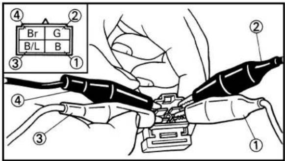
text_image
④ Br G B/L B ② ③ ① ④ ③ ②- Inspect:
- Fuel pump relay conduct Use 12V battery.
| Battery (+) lead → | Black lead 1 |
| Battery (-) lead → | Green lead 2 |
| Tester (+) lead → | Black/Blue lead 3 |
| Tester (-) lead → | Brown lead 4 |
| B/L3 | Br Tester selector position | ||
| Connected to battery | |||
| Not connected to battery |
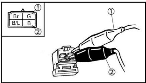
text_image
① Br G B/L B ② ① ②Continuous while connected to the battery → Replace.
Not continuous while not connected to the battery → Replace.
- Inspect:
- Fuel pump relay resistance Out of specification → Replace.
| Tester (+) lead → | Green lead 1 |
| Tester (-) lead → | Black lead 2 |
| Fuel pump relay resistance position | Tester selector | |
| 72~80 Ω at 20°C (68°F) | Ω × 10 |
EC674000
FUEL PUMP OPERATION
CAUTION:
Do not operate the fuel pump on an empty fuel tank because it may damage the pump.
- Loosen the drain plug (carburetor) and drain the fuel from the float chamber.

natural_image
Technical line drawing of a mechanical assembly with numbered component (no text or symbols)
text_image
Diagram showing cable connection with labeled components and a magnified inset of a connector block labeled B/B/L- Install:
- Drain plug
-
Turn the fuel cock to "ON".
-
Inspect:
- Fuel pump ①
Operation sound when the main switch is moved to "RUN" → OK
EC675000
FUEL PUMP COIL INSPECTION
-
Disconnect the fuel pump coupler.
-
Inspect:
- Fuel pump coil resistance
Out of specification → Replace.
| Tester (+) lead → | Black/Blue lead 1 |
| Tester (-) lead → | Black lead 2 |
| Fuel pump coil resistance position | Tester selector | |
| 1~3 Ω at20°C (68°F) | Ω × 1 |
EC676000
FUEL PUMP INSPECTION
CAUTION:
Do not operate the fuel pump on an empty fuel tank because it may damage the pump.
-
Remove the fuel outlet hose from the fuel pump.
-
Connect another plastic hose ① to the fuel pump and place its other end into a container.

natural_image
Technical line drawing of a mechanical assembly with no visible text or symbolsFUEL PUMP SYSTEM
ELEC


text_image
Diagram showing car seatbelt connection with labeled parts and a magnified inset showing B and B/L connectors- Turn the fuel cock to "ON".
- Disconnect the fuel pump coupler.
- Connect 12V battery to the fuel pump coupler.
Battery (+) lead → Black/Blue lead ①
Battery (-) lead → Black lead ②
text_image
Technical diagram showing a hand holding a cable labeled with parts numbered ① and ②, likely illustrating a mechanical or electrical assembly.- Inspect:
- Fuel pump ①
No fuel flows from the plastic hose ② → Replace.
EC700000
TUNING
EC710000
ENGINE
EC711011
Carburetor setting
- The role of fuel is not only to produce motive power but also to cool the engine and, in the case of a 2-stroke engine, to lubricate it. Therefore, too lean a mixture (of air and fuel) tends to cause an abnormal combustion (i.e., detonation), whereas too rich a mixture makes it difficult for the engine to develop its full performance, with the result that in some cases the spark plug may be fouled, causing the engine to stop running.
- The richness of the air-fuel mixture required for the engine will vary with atmospheric conditions of the day and therefore, the settings of the carburetor must be properly suited to the atmospheric conditions (air pressure, humidity and temperature).
- As a basic setting method, only the factory set main jet is first changed to check for the discoloration of the spark plug(s) and piston(s) at full throttle in 6th and then the setting is determined at mid-open throttle.
※ Recording and storing the data on the settings, weather conditions, road surface conditions of the circuit, lap times, etc. will enable quick setting under different conditions at a later time.
EC712000
Atmospheric conditions and carburetor setting
| Air temp. | Humidity pressure (altitude) | Air | Setting | |
| High High | Low (high) | Richer Leaner | ||
| Low Low | High (low) | Leaner Richer |
The reason for the above tendency is that the richness or leanness of a fuel mixture depends on the density of the air (i.e. the concentration of oxygen in it).
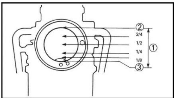
text_image
① ② 3/4 1/2 1/4 1/8 ③That is:
- Higher temperature expands the air with its resultant reduced density.
- Higher humidity reduces the amount of oxygen in the air by so much of the water vapor in the same air.
- Lower atmospheric pressure (at a high altitude) reduces the density of the air.
EC714000
Effects of setting parts in relation to throttle valve opening
| Setting parts | Throttle valve opening | |||||
| 0 | 1/8 | 1/4 | 1/2 | 3/4 | 7/8 1/1 | |
 | ||||||
 | ||||||
 | ||||||
 | ||||||
 | ||||||
 | ||||||
① Throttle valve opening
② Full-open
③ Full-closed
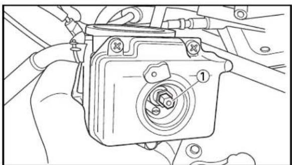
natural_image
Line drawing of a hand holding a mechanical component with no visible text or symbolsEC71E003
Basic process of carburetor setting
Ex-factory setting is on the richer side, which should basically have no problems with the brake-in procedure.
Refer to "STARTING AND BREAK-IN" section in the CHAPTER 1.
- Adjustment of main jet
Use a main jet ① with a smaller calibration number if the engine does not develop more than 12,000 rpm after a few laps of the circuit when the water temperature becomes stable [55°C (131°F) or more].
Example:#560 → #540

Next run a few laps of the circuit with this setting and check for any difference in engine revolutions. If no difference is noticed, use a main jet with a much smaller calibration number.
Example: #540 → #500
A

natural_image
Two mechanical components: a cylindrical engine and a hollow cylinder (no text or symbols visible)B

natural_image
Close-up of two mechanical components: a cylindrical engine and a hollow cylinder (no text or symbols visible)C
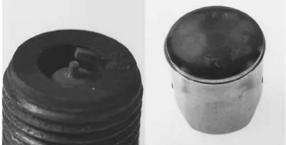
natural_image
Two black cylindrical objects, one showing a circular opening and the other a lid with a flat top (no text or symbols visible)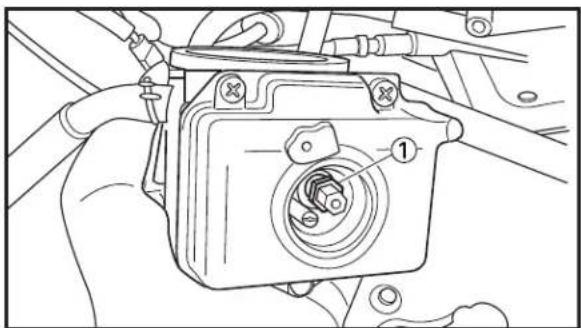
text_image
Technical diagram showing a mechanical component with labeled parts, likely for assembly or maintenance instructions.Factory-set main jet #560
- Checking of spark plug and piston for discoloration
Repeat the adjustment in the above "1" several times. If the engine begins to run at more than 12,000 rpm at full throttle, proceed to the "spark plug chopping" step (refer to P7-9) to check for the discoloration of the spark plug(s) and piston(s).
Refer to the photo for judgment on the discoloration.
As a novice will find it difficult to determine how much smaller number main jet can be used just by looking at discoloration, he should consult an experienced person for his own experience, too.
Whether the setting is proper or not can be judged by engine revolutions.
Approximate criteria for such judgment are given below, on condition that the secondary reduction ratio is fit for conditions of the circuit.
•13,000 rpm in 1st and 2nd
•12,500 rpm in 5th and 6th
A Normal
B Over burned (too lean)
C Oil fouled (too rich)
- Adjustment of main nozzle
The main nozzle ① adjustment follows the completion of the adjustment of the main jet. Check that engine revolutions smoothly respond to throttle opening from where throttle is about to be opened to 1/2 throttle opening. Use a main nozzle of a smaller size if engine revolutions appear to falter at the beginning of throttle opening and then suddenly respond to further throttle opening.
Example:S-4 → S-3
SETTING
TUN

If the main jet is fully adjusted with not much allowance for discoloration, use a main jet which is approximately #20 lager.
Run a few laps of the circuit to check the engine for response to revolutions. Also check for the discoloration of the spark plug(s) and piston(s).
Use a main jet of a smaller size if good response to engine revolutions is achieved with an allowance for the discoloration of the spark plug(s) and piston(s).
On the other hand, if the use of a different main nozzle appears to produce less power, change to a main nozzle of a larger size.
Example:S-1 → S-2
Factory-set main nozzle \$-4
NOTE:
Difference between individual riders or difference between circuit layouts greatly affect the main nozzle setting.
- Rider who frequently uses mid-open throttle
- Circuit that requires frequent throttle opening and closing
- Wet environment
Conditions as mentioned above require a longer period of throttle closing, resulting in the drawn in mixture staying longer in the crankcase. Such setting in turn will inevitably cause the mixture to be richer at the next throttle opening, a main nozzle of a smaller size has to be used.
EC71F002
Carburetor settings by correction coefficient
Now you should be able to understand the essentials of basic carburetor setting from an explanation given under "Basic process of carburetor setting" (P7-2).
Next is an explanation of how to select a main jet to deal with changes in weather conditions by means of a correction coefficient.
NOTE:
- Before this correction coefficient can be used, satisfactory carburetor setting must have been made.
- This correction coefficient can not be used if there is a change in specification (e.g., ignition timing, compression ratio, etc.).
Illustration:
Suppose the best setting was represented by a #450 main jet at an air pressure of 1013 hPa (760 mmHg) and an air temperature of 20°C (68°F) in the previous riding.
In this riding, there has been a substantial change in conditions; namely, an air pressure of 1007 hPa (755 mmHg) and an air temperature of 30°C (86°F).
- Refer to a table of correction coefficients (P7-6) to find the correction coefficient for the previous riding.
The correction coefficient A=100.0
- Find the correction coefficient for this time.
The correction coefficient B=96.1
- Use the following equation to calculate the size of a main jet needed in this particular case.
Previous main jet size × B/A = Currently required main jet size
450 × 96.1/100 = 432.5
Thus, a #430 main jet can be selected.
CAUTION:
If a change in conditions require a main jet of a larger size, use the size to which #20 is added for safety.
NOTE:
- Since this correction coefficient table lacks a column for humidity, it is advisable to check the degree of discoloration of the spark plug(s) for final selection according to an explanation under “Atmospheric conditions and carburetor setting” (P7-1).
- As the main nozzle is more susceptible to other than atmospheric conditions, no correction coefficient is used for main nozzle setting.
EC71G002
Table of correction coefficients for carburetor setting
| Air pressure hPa (mmHg) | Air temperature °C (°F) | Altitude m (ft) | |||||||||
| -5 (23) | Zero (32) | 5 (41) | 10 (50) | 15 (59) | 20 (68) | 25 (77) | 30 (86) | 35 (95) | 40(104) | ||
| 1040 (780) | 112.2 | 110.2 | 108.2 | 106.3 | 104.4 | 102.6 | 100.9 | 99.3 | 97.7 | 96.1 -220 (-722) | |
| 1033 (775) | 111.5 | 109.4 | 107.5 | 105.6 | 103.7 | 102.0 | 100.3 | 98.6 | 97.0 | 95.5 -165 (-541) | |
| 1027 (770) | 110.8 | 108.7 | 106.8 | 104.9 | 103.1 | 101.3 | 99.6 | 98.0 | 96.4 | 94.8 -110 (-361) | |
| 1020 (765) | 110.0 | 108.0 | 106.1 | 104.2 | 102.4 | 100.7 | 99.0 | 97.3 | 95.8 | 94.2 -55 (-180) | |
| 1013 (760) | 109.3 | 107.3 | 105.4 | 103.5 | 101.7 | 100.0 | 98.3 | 96.7 | 95.1 | 93.6 Zero (Zero) | |
| 1007 (755) | 108.6 | 106.6 | 104.7 | 102.9 | 101.1 | 99.3 | 97.7 | 96.1 | 94.5 | 93.0 56 (184) | |
| 1000 (750) | 107.9 | 105.9 | 104.0 | 102.2 | 100.4 | 98.7 | 97.0 | 95.4 | 93.9 | 92.4 112 (367) | |
| 993 (745) | 107.2 | 105.2 | 105.2 | 103.3 | 101.5 | 99.7 | 99.7 | 98.0 | 96.4 | 94.8 | 93.3 91.8 168 (551) |
| 987 (740) | 106.5 | 104.5 | 104.5 | 102.6 | 100.8 | 99.1 | 99.1 | 97.4 | 95.7 | 94.2 92.6 91.1 224 (735) | |
| 980 (735) | 105.7 | 103.8 | 103.8 | 101.9 | 100.1 | 98.4 | 98.4 | 96.7 | 95.1 | 93.5 92.0 90.5 281 (922) | |
| 973 (730) | 105.0 | 103.1 | 103.1 | 101.2 | 99.4 | 97.7 | 97.7 | 96.1 | 94.4 | 92.9 91.4 89.9 338 (1,109) | |
| 967 (725) | 104.3 | 102.4 | 102.4 | 100.5 | 98.8 | 97.1 | 97.1 | 95.4 | 93.8 | 92.2 90.7 89.3 396 (1,299) | |
| 960 (720) | 103.6 | 101.7 | 101.7 | 99.8 | 98.1 | 96.4 | 96.4 | 94.7 | 93.1 | 91.6 90.1 88.7 453 (1,486) | |
| 953 (715) | 102.9 | 101.0 | 101.0 | 99.2 | 97.4 | 95.7 | 95.7 | 94.1 | 92.5 | 91.0 89.5 88.1 512 (1,680) | |
| 947 (710) | 102.1 | 100.3 | 100.3 | 98.5 | 96.7 | 95.0 | 95.0 | 93.4 | 91.9 | 90.3 88.9 87.5 570 (1,870) | |
| 940 (705) | 101.4 | 99.6 | 99.6 | 97.8 | 96.0 | 94.4 | 94.4 | 92.8 | 91.2 | 89.7 88.2 86.8 629 (2,064) | |
| 933 (700) | 100.7 | 98.9 | 98.9 | 97.1 | 95.4 | 93.7 | 93.7 | 92.1 | 90.6 | 89.1 87.6 86.2 688 (2,257) | |
| 927 (695) | 100.0 | 98.1 | 98.1 | 96.4 | 94.7 | 93.0 | 93.0 | 91.4 | 89.9 | 88.4 87.0 85.6 747 (2,451) | |
| 920 (690) | 99.3 | 97.4 | 97.4 | 95.7 | 94.0 | 92.4 | 92.4 | 90.8 | 89.3 | 87.8 86.4 85.0 807 (2,648) | |
| 913 (685) | 98.5 | 96.7 | 96.7 | 95.0 | 93.3 | 91.7 | 91.7 | 90.1 | 88.6 | 87.2 85.7 84.4 867 (2,845) | |
| 907 (680) | 97.8 | 96.0 | 96.0 | 94.3 | 92.6 | 91.0 | 91.0 | 89.5 | 88.0 | 86.5 85.1 83.8 928 (3,045) | |
| 900 (675) | 97.1 | 95.3 | 95.3 | 93.6 | 92.0 | 90.4 | 90.4 | 88.8 | 87.3 | 85.9 84.5 83.1 989 (3,245) | |
| 893 (670) | 96.4 | 94.6 | 94.6 | 92.9 | 91.3 | 89.7 | 89.7 | 88.2 | 86.7 | 85.2 83.9 82.5 1,050 (3,445) | |
| 887 (665) | 95.7 | 93.9 | 93.9 | 92.2 | 90.6 | 89.0 | 89.0 | 87.5 | 86.0 | 84.6 83.2 81.9 1,111 (3,645) | |
| 880 (660) | 94.9 | 93.2 | 93.2 | 91.5 | 89.9 | 88.3 | 88.3 | 86.8 | 85.4 | 84.0 82.6 81.3 1,173 (3,848) | |
| 873 (655) | 94.2 | 92.5 | 92.5 | 90.8 | 89.2 | 87.7 | 87.7 | 86.2 | 84.7 | 83.2 82.0 80.7 1,236 (4,055) | |
| 867 (650) | 93.5 | 91.8 | 91.8 | 90.1 | 88.5 | 87.0 | 87.0 | 85.5 | 84.1 | 82.7 81.4 80.1 1,299 (4,262) | |
| 860 (645) | 92.8 | 91.1 | 91.1 | 89.4 | 87.9 | 86.3 | 86.3 | 84.9 | 83.4 | 82.1 80.7 79.4 1,362 (4,469) | |
| 853 (640) | 92.1 | 90.4 | 90.4 | 88.8 | 87.2 | 85.7 | 85.7 | 84.2 | 82.8 | 81.4 80.1 78.8 1,425 (4,675) | |
| 847 (635) | 91.3 | 89.7 | 89.7 | 88.1 | 86.5 | 85.0 | 85.0 | 83.6 | 82.2 | 80.8 79.5 78.2 1,489 (4,885) | |
| 840 (630) | 90.6 | 89.0 | 89.0 | 87.4 | 85.8 | 84.3 | 84.3 | 82.9 | 81.5 | 80.2 78.9 77.6 1,554 (5,099) | |
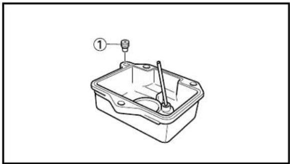
natural_image
Technical line drawing of a mechanical component with labeled parts (no text or symbols present)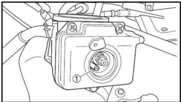
natural_image
Line drawing of a hand holding a mechanical component with a circular dial and labeled part (1), no text or symbols present.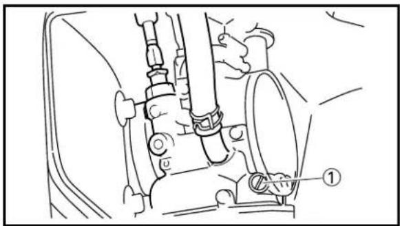
natural_image
Technical line drawing of a mechanical assembly with no visible text or symbols
natural_image
Technical line drawing of a spark plug (no text or symbols)EC71H040
Other setting parts
1. Power jet ①
Power jet is not basically changed. Since the areas of the main jet and main nozzle overlap each other, special knowledge is required for a setting change.
A larger size results in a richer mixture and a smaller size in a leaner mixture.
| Factory-set power jet #55 |
2. Pilot jet ①
The pilot jet is used in relation to the engine response at small throttle opening. This is changed when the main nozzle setting is not enough.
A larger size results in a richer mixture and a smaller size in a leaner mixture.
| Factory-set pilot jet #40 |
3. Pilot air screw ①
The pilot air screw relates to the engine response at a smaller opening than for the pilot jet.
This setting may be changed for want of time or in emergency, but it is basically set at the factory-set pilot air screw position.
| Factory-set pilot air screw position | 1-1/2 turns out |
4. Spark plug
The spark plug heat range is not basically changed.
Constant attention to the discoloration of the spark plug and piston head will enable you to tell to some extent whether the setting is good or bad.
| Standard spark plug | R6179A-105P/NGK |
NOTE:
For the effects each setting part has, refer to "Effects of setting parts in relation to throttle valve opening" (P7-2).

text_image
Exploded view diagram of a mechanical assembly with numbered parts for identificationEC71Q021
Carburetor setting parts
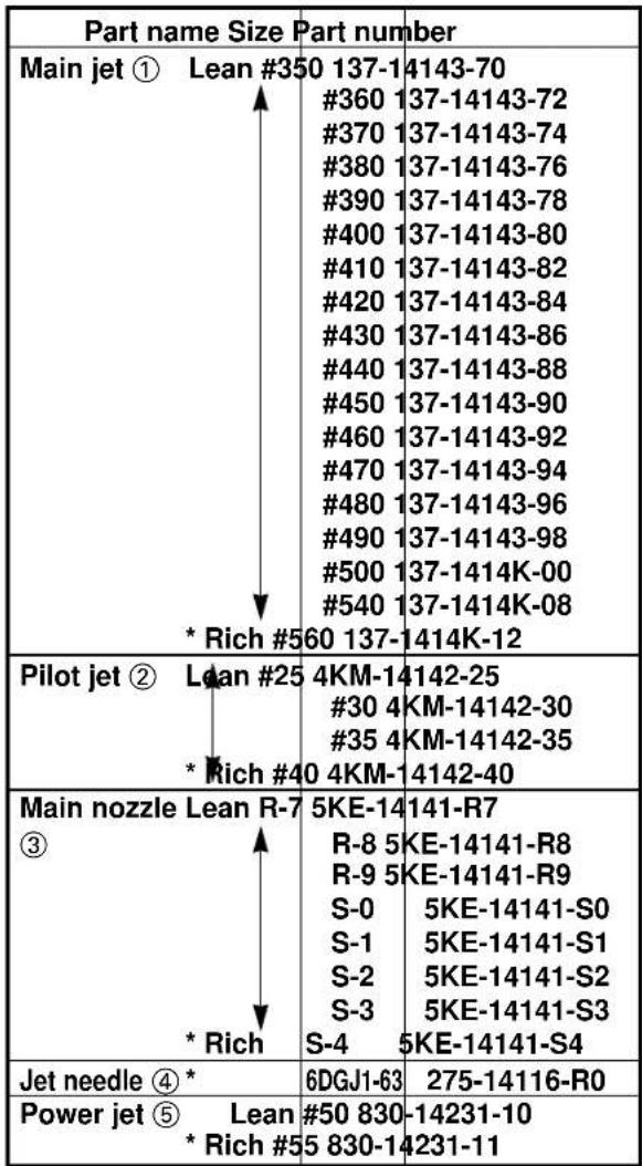
text_image
Part name Size Part number Main jet ① Lean #350 137-14143-70 #360 137-14143-72 #370 137-14143-74 #380 137-14143-76 #390 137-14143-78 #400 137-14143-80 #410 137-14143-82 #420 137-14143-84 #430 137-14143-86 #440 137-14143-88 #450 137-14143-90 #460 137-14143-92 #470 137-14143-94 #480 137-14143-96 #490 137-14143-98 #500 137-1414K-00 #540 137-1414K-08 * Rich #560 137-1414K-12 Pilot jet ② Lean #25 4KM-14142-25 #30 4KM-14142-30 #35 4KM-14142-35 * Rich #40 4KM-14142-40 Main nozzle Lean R-7 5KE-14141-R7 ③ R-8 5KE-14141-R8 R-9 5KE-14141-R9 S-0 5KE-14141-S0 S-1 5KE-14141-S1 S-2 5KE-14141-S2 S-3 5KE-14141-S3 * Rich S-4 5KE-14141-S4 Jet needle ④ * 6DGJ1-63 275-14116-R0 Power jet ⑤ Lean #50 830-14231-10 * Rich #5 830-14231-11* Factory installed
NOTE:
Use a #500 main jet when selecting a next smaller size jet than a #540.
EC71J010
Plug chop
When checking the discoloration of the spark plug and piston head, move the main switch to "OFF" while running along a straight lane at full throttle, disengage the clutch at the same time and stop the engine. Then let your machine go back to the pit by inertia. This is called a "plug chop".
CAUTION:
- When you do a “plug chop”, pay attention to your surrounding environment to avoid interference with other riders.
- Do not shift down while riding your machine by inertia (as it may cause a seizure of the clutch push rod and ball).

natural_image
Pure technical line drawing of a mechanical flange or bracket (no text or symbols)EC71K010
Setting of cylinder gasket
The use of the supplied gaskets of different thicknesses makes it possible to change the combustion chamber volume.
Not much torque is felt with slow engine acceleration → Reduce the combustion chamber volume.
Torque is felt with no higher revolutions → Expand the combustion chamber volume.
| Thickness | Actual combustion chamber volume | Type |
| 0.6 mm (0.024 in) | 9.66 cm^3 (0.340 Imp oz, 0.327 US oz) | STD |
| 0.5 mm (0.020 in) | 9.43 cm^3 (0.332 Imp oz, 0.319 US oz) | Supplying parts |
| 0.38 mm (0.015 in) | 9.20 cm^3 (0.324 Imp oz, 0.311 US oz) | |
| 0.3 mm (0.012 in) | 8.98 cm^3 (0.316 Imp oz, 0.304 US oz) | |
| 0.2 mm (0.008 in) | 8.75 cm^3 (0.308 Imp oz, 0.296 US oz) |
NOTE:
- Finish the break-in before changing the gasket.
- A change of 0.1 mm (0.004 in) for the gasket causes a change of approximately 0.23 cm ^3 (0.008 Imp oz, 0.008 US oz) of the combustion chamber volume.
- After break-in, change to an appropriate gas- ket to allow the piston protrusion to be -0.15 mm (-0.006 in) to 0.05 mm (0.002 in).
CAUTION:
- Piston protruding amount must be a maximum 0.15 mm (0.006 in). Above this value, the piston and cylinder head may contact each other.
- Too much random piston protrusion at low temperature may develop an abnormal combustion (detonation), which may adversely affect the intended performance of the engine.
A Air temperature
B Piston protruding amount
EC71T000
Cylinder gasket setting parts
| Part number Size (thickness) |
| 5KE-11351-60 * t=0.6 mm (0.024 in) |
| 5KE-11351-50 t=0.5 mm (0.020 in) |
| 5KE-11351-40 t=0.38 mm (0.015 in) |
| 5KE-11351-30 t=0.3 mm (0.012 in) |
| 5KE-11351-20 t=0.2 mm (0.008 in) |
* Factory installed

text_image
Technical diagram of a mechanical measurement device with labeled parts and an inset gauge showing directional arrows.EC71L003
Measuring piston protrusion
- Install the dial gauge ① and dial gauge stand ② to the cylinder contact surface and set the scale of the dial gauge to zero.

Dial gauge and stand: YU-3097/90890-01252 Offset dial stand: YU-1037
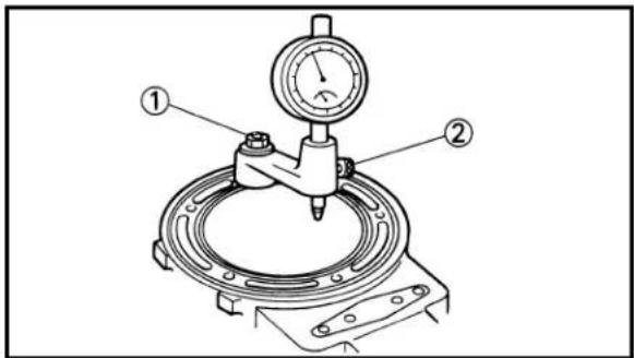
text_image
Technical diagram of a mechanical testing setup with labeled components ① and ②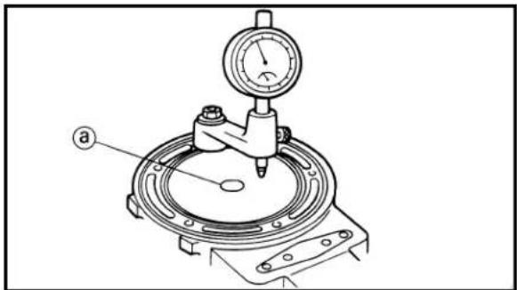
text_image
a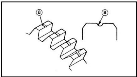
text_image
Technical diagram showing a zigzag mechanical component with labeled parts 'a' and an arrow pointing to a separate section.- Loosen the stand installation bolt ①, then rotate the dial gauge stand and set it close to the center of the piston. Tighten the stand installation bolt again.
NOTE:
Do not loosen the dial gauge installation bolt ② while doing the above.
- Set the piston at top dead center (TDC), then measure the piston protrusion.
NOTE:
For measurement, avoid the top center projected area ⓐ on the piston head but measure several positions above the piston pin as close to the center as possible. The average of these measurements indicates the piston protrusion.
EC71N001
Selection of transmission gear ratio
The following gear sets are contained in the packing (or optional) to allow the rider to change the gear ratios according to the circuit condition or rider's preference.
CAUTION:
Select the transmission gears so that the number of grooves in the wheel gear match that of the pinion gear as shown below. Trouble may be occurred if the selection is different than that listed below.
a Groove
1st gear
| Gear ratio Part number | Number of groove | |||
| Factory installed 34/18 | (1.889) | 5KE-17211-20/5KE-17411-20 | 2 | |
| Supplying part | 28/14 (2.000) | 5KE-17211-10/5KE-17411-10 | 1 | |
2nd gear
| Gear ratio Part number | Number of groove | |
| Factory installed 31/21 | (1.476) 4DP-17221-11/4DP-17121-11 1 | |
| Optional part 27/19 (1.421) 5F7-17221-21/5F7-17121-21 2 | ||
| Optional part 28/18 (1.556) 5F7-17221-00/5F7-17121-00 – |
3rd gear
| Gear ratio Part number | Number of groove | |
| Factory installed 29/23 | (1.261) 5KE-17231-00/5KE-17131-00 – | |
| Optional part/ Supplying part | 25/21 (1.190) 5KE-17231-20/5KE-17131-10 2/1 | |
| Supplying part 26/21 (1.238) 5KE-17231-10/5KE-17131-10 1 |
6th gear
| Gear ratio Part number | Number of groove | |
| Factory installed 20/22 (0.909) 5KE-17261-00/5KE-17191-00 1 | ||
| Supplying part 22/25 (0.880) 5KE-17261-10/5KE-17161-10 2 |
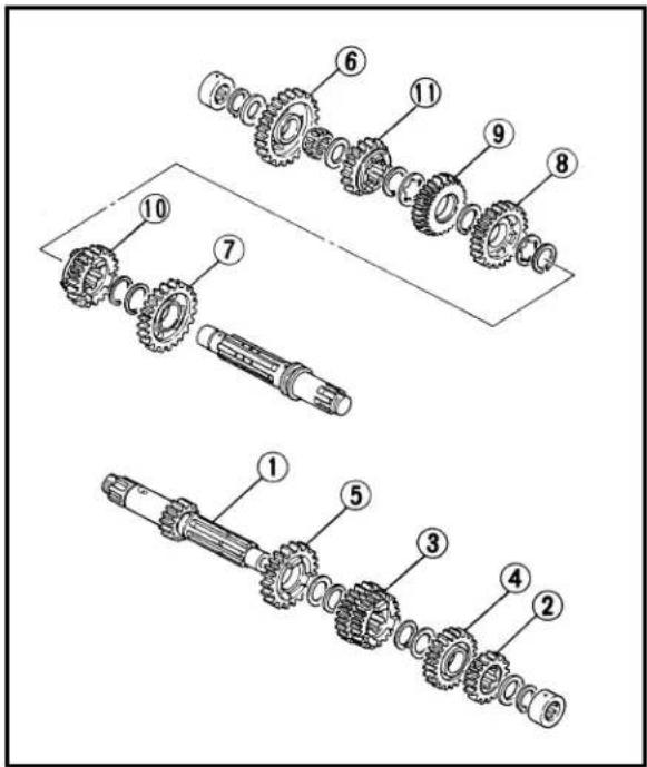
text_image
Technical diagram showing exploded view of mechanical gear assembly with numbered componentsEC71U011
Transmission setting parts
| Part name Size Part number | ||
| Main axle 1 14T 5KE-17411-10* 18T 5KE-17411-20 | ||
| 2nd pinion gear 2 Δ 18T 5F7-17121-00Δ 19T 5F7-17121-21* 21T 4DP-17121-11 | ||
| 3rd/4th pinion 21T/25T 5KE-17131-10gear 3 * 23T/25T 5KE-17131-00 | ||
| 5th pinion gear 4 * 27T 5F7-17151-01 | ||
| 6th pinion gear 5 * 22T 5KE-17161-0025T 5KE-17161-10 | ||
| 1st wheel gear 6 * 28T 5KE-17211-1034T 5KE-17211-20 | ||
| 2nd wheel gear 7 Δ 27T 5F7-17221-21Δ 28T 5F7-17221-00* 31T 4DP-17221-11 | ||
| 3rd wheel gear 8 Δ 25T 5KE-17231-2026T 5KE-17231-10* 29T 5KE-17231-00 | ||
| 4th wheel gear 9 * 27T 5KE-17241-00 | ||
| 5th wheel gear 10 * 26T 3YL-17251-00 | ||
| 6th wheel gear 11 * 20T 5KE-17261-0022T 5KE-17261-10 |
* Factory installed
NOTE:
- The mark shows that this part is not supplied together and that it is available on order as a YAMAHA genuine part.
- 3rd/4th pinion gear 5KE-17131-10 allows for a combination of 3rd wheel gear 5KE-17231-10 or 5KE-17231-20. No combination can be selected for the factory installed 5KE-17231-00.
EC720000
CHASSIS
EC72J001
Chassis setting
How to go about setting the chassis
- Measure the stroke of the front and rear suspension to get an idea of the operation.
- If the time increases, the stroke increases.
- If the tire grip becomes firmer, the stroke increases.
(On the other hand, the stroke decreases on rainy weather.)
- Rider's position and posture affect the stroke.
- Be careful not to allow the suspension to bottom out.
- Start the setting with the preload.
Next, go to the damping force adjustment, and if this not enough, then adjust the machine height.
(On the side where the machine height is greater the stroke increases; whereas it decreases on the side with a smaller machine height.)
- If the damping force is increased either on the compression or the expansion side, it results in less smooth movement, so do not depart too far from the standard settings.
- Adjust the machine height in an increment of mm (in).
- If you lose your way while doing the setting, go back to the standard settings.
- Oil level adjustment in the front fork produces a greater effect in further stroke than in mid stroke.
(Increase or decrease the oil level in an approximately 5\~10 mm (0.20\~0.39 in) interval.)
natural_image
Line drawing of a motorcycle showing internal components and suspension (no text or symbols)EC72M001
Tire and machine's posture
If a non-designated tire is used, the difference in radius between the front and the rear tire may affect the machine's posture.
To keep the machine in a proper posture, adjust the front fork top end or seat height.
Basically, with a larger radius tire, lower the machine's posture and vice versa.
[Front]
| Tire brand | Tire circumference Tire radius Front fork top end | |
| *3.10/4.80 R17DUNLOP KR106 | About 1,875 mm (73.8 in) About 298.5 mm (11.8 in) 13 mm (0.51 in) | |
| 120/70 R17DUNLOP MR977 | About 1,885 mm (74.2 in) About 300 mm (11.8 in) 11.5 mm (0.45 in) |
*Designated tire
[Rear]
| Tire brand | Tire circumference Tire radius Seat height | |
| *165/55 R17DUNLOP KR108 | About 1,975 mm (77.8 in) About 314.5 mm (12.4 in) 24 mm (0.94 in) | |
| 165/50 R17DUNLOP KR244 | About 1,957 mm (77.0 in) About 311.5 mm (12.3 in) 25.5 mm (1.00 in) |
*Designated tire
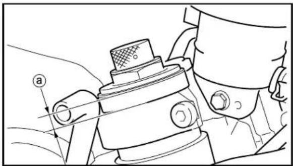
natural_image
Technical line drawing of a mechanical component with no visible text or symbolsExample:
If the front tire radius is 1 mm (0.04 in) larger, lower the front posture by 1 mm (0.04 in) by increasiry the front fork top end ⓐ by 1 mm (0.04 in). If the rear tire radius is 2 mm (0.08 in) smaller, raise the rear posture by 2 mm (0.08 in) by decreasiry the adjuster set length ⓑ by 1 mm (0.04 in).
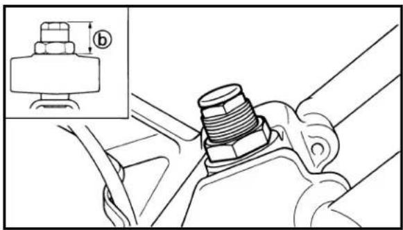
natural_image
Technical illustration of a mechanical assembly with a threaded bolt and bracket, showing no text or symbols.NOTE:
- Find the tire radius by calculating the measured circumference of the tire.
- A change of 1 mm (0.04 in) in the front fork top end results in a change of about 1 mm (0.04 in) in the front posture. A change of 1 mm (0.04 in) in the adjuster set length results in a change of about 2 mm (0.08 in) in the rear posture.
EC72K014
Settings
For full use of engine performance and safe riding, set the suspension as follows. (Ex-factory settings are intended for a rider approximately 170 cm (66.9 in) in height and approximately 60 kg (132 lb) in weight.)

text_image
INSU-LOCK TIE BUMP RUBBER
text_image
A APPROX. 7 mm (0.28 in) DUST LIP APPROX. 10 mm (0.39 in) (In case of) (grease) (In case of) (insu-lock tie) (EXAMPLE) 25 mm (0.98 in) GREASED In the case of the above, remaining stroke is 15 mm (0.59 in).
text_image
B 5mm (0.20 in) IN BUMP RUBBER (EXAMPLE) 10 mm (0.39 in) In the case of the above, remain- ing stroke is 15 mm (0.59 in).1. Preparations
To check for the remaining stroke in the front and rear suspension, either install a thin insu-lock tie or apply a small amount of grease at the front fork inner tube and at the rear shock absorber rod.
2. Settings
At the beginning of the break-in period, always record the remaining stroke as data.
To judge front and rear balance in relation to the machine height, the usual way is to shift from full braking to turning and get the feel when the clipper riding.
After making an actual run, proceed to the settings for a target of a 5\~10 mm (0.20\~0.39 in) remaining stroke for front and a 10 \~ 20 mm (0.39\~0.79 in) remaining stroke for rear.
Basically, the best settings can be obtained by repeating the following steps.
NOTE:
The figures show the bottom-out positions of the front and rear suspension.
A Front
B Rear
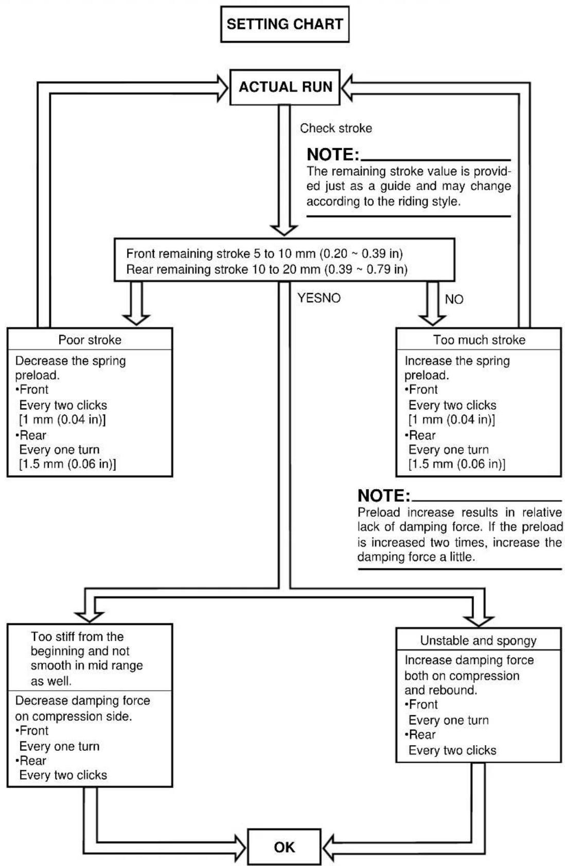
flowchart
graph TD
    A["SETTING CHART"] --> B["ACTUAL RUN"]
    B --> C["Check stroke"]
    B --> D["FRONT remaining stroke 5 to 10 mm (0.20 ~ 0.39 in)<br>Rear remaining stroke 10 to 20 mm (0.39 ~ 0.79 in)"]
    B --> E["YESNO"]
    B --> F["NO"]
    C --> G["Poor stroke<br>Decrease the spring preload.<br>•Front<br>Every two clicks<br>[1 mm (0.04 in)"]
•Rear
Every one turn
[1.5 mm (0.06 in)]]
    D --> H["Too much stroke<br>Increase the spring preload.<br>•Front<br>Every two clicks<br>[1 mm (0.04 in)"]
•Rear
Every one turn
[1.5 mm (0.06 in)]]
    E --> I["NOTE: The remaining stroke value is provided just as a guide and may change according to the riding style."]
    F --> J["NOTE: Preload increase results in relative lack of damping force. If the preload is increased two times, increase the damping force a little."]
    G --> K["Too stiff from the beginning and not smooth in mid range as well.<br>Decrease damping force on compression side.<br>•Front<br>Every one turn<br>•Rear<br>Every two clicks"]
    H --> L["Unstable and spongy<br>Increase damping force both on compression and rebound.<br>•Front<br>Every one turn<br>•Rear<br>Every two clicks"]
    I --> M["OK"]
    L --> M
    K --> M
    L --> M
EC71P011 Selection of the secondary reduction ratio (Sprocket)
Secondary reduction = of driven sprocket teethNumber of drive sprocket teeth ratio
| Factory-set secondary reduction ratio | 36/14 (2.571) |
| Drive sprocket\Driven sprocket | 35T 36T | 37T 38T | 39T 40T | |||
| 14T 2.500 2.5 | 71 | 2.643 | 2.7 | 14 | 2.786 | 2.857 |
| 15T 2.333 2.4 | 00 | 2.467 | 2.5 | 34 | 2.600 | 2.666 |
| 16T 2.188 2.2 | 50 | 2.313 | 2.3 | 75 | 2.438 | 2.500 |
The larger value, the higher speed ratio The smaller value, the lower speed ratio

text_image
Diagram illustrating mechanical components with labeled parts, including gear and gear-like parts.EC72N000 Drive and driven sprockets setting parts
| Part name Size | Part number |
| Drive sprocket 1 * 14T 93834-1417815T 93834-1507916T 93834-16104 | |
| Driven sprocket 2 35T 5KE-25435-10* 36T 5KE-25436-1037T 5KE-25437-1038T 5KE-25438-1039T 5KE-25439-1040T 5KE-25440-10 | |
* Factory installed
EC72L003
Chassis setting troubleshooting

flowchart
graph TD
    A["<Symptom>"] --> B["Chattering (Small rebounds, Bottoming (full stroke) • Increase spring preload.<br>up-and-down • Increase damping force for compression."]
    A --> C["Too stiff feeling"]
    A --> D["Spongy feeling"]

    B --> B1["Further in stroke • Increase damping force for compression, or decrease damping force for rebound."]
    B --> B2["Too stiff (poor stroke) • Decrease spring preload."]
    B --> B3["Looseness in parts • Check bolts, bearings, etc. as well as their installation."]
    B --> B4["Tire/Rim • Recheck balance."]
    B --> B5["Poor operation • Check the shock absorber."]
    B --> B6["Too stiff (poor stroke) • Decrease spring preload."]
    B --> B7["Bottoming (full stroke) • Increase spring preload."]
    B --> B8["Poor of damping force"]
    B --> B9["Too soft"]
    C --> C1["(Check rod, inner tube, etc. for bending. If bent, replace.)"]
    C --> C2["Check for any deviation from center after tightening front wheel axle.<br>(Replace if deviated in any way.)"]
    C --> C3["Too much tightened bolts for front fork outer tube → Retorque the bolts to specification (handle crown, under bracket, steering damper stay, handlebar)."]
    C --> C4["Decrease damping force (for both compression and rebound)."]
    C --> C5["Increase oil level (for front fork only)."]
    C --> C6["Increase damping force for compression, o decrease damping force for rebound."]
    D --> D1["Increase damping force (for both compression and rebound)."]
    D --> D2["Increase spring preload."]
Handlebar fluctuating
Poor of front load • Decrease spring preload (for front).
- Increase front fork top end.
- Increase rear height.
- Increase spring preload (for rear).
Too soft of front • Increase spring preload (for front).
- Increase damping force (for front).
Poor corner maneuvering
Machine tends to incline • Increase rear height.
too much backward. • Increase spring preload (for rear).
(Too big caster angle) • Decrease damping force for rebound (for
rear).
- Increase front fork top end.
- Decrease spring preload (for front).
Too much knifing at cornering
Machine tend to incline • Decrease front fork top end.
too much forward. • Decrease rear height.
(Too small caster angle) • Increase spring preload (for front).
- Increase damping force for compression (for front).
Front dives in too early • Increase damping force for compression (for front).
Swinging on
(bounding) Too much damping force • Decrease damping force for rebound.
over gaps for rebound
Bottoming
- Increase spring preload.
EC740002
Setting record table
The data shown here is an example of entry. For your actual use, copy the necessary data.
| Event name | ||||
| Date | ||||
| Weather | ||||
| Place |
Setting specs:
| Ignition timing | ||||
| Spark plug | ||||
| CarburetorMain jetPower jetJet needleMain nozzlePilot jetPilot air screwFloat height | ||||
| Gearing1st2nd3rd4th5th6thSecondary | ||||
| Front forkSpring rateSpring preloadRebound dampingCompression dampingTop endOil capacityOil level | ||||
| Rear shockSpring fitting lengthSpring rateRebound dampingCompression dampingSeat height | ||||
| Front tire (pressure) | ||||
| Rear tire (pressure) | ||||
| Fuel consumption | ||||
| Event name | ||||
| Date | ||||
| Weather | ||||
| Place |
Setting specs:
| Ignition timing | ||||
| Spark plug | ||||
| CarburetorMain jetPower jetJet needleMain nozzlePilot jetPilot air screwFloat height | ||||
| Gearing1st2nd3rd4th5th6thSecondary | ||||
| Front forkSpring rateSpring preloadRebound dampingCompression dampingTop endOil capacityOil level | ||||
| Rear shockSpring fitting lengthSpring rateRebound dampingCompression dampingSeat height | ||||
| Front tire (pressure) | ||||
| Rear tire (pressure) | ||||
| Fuel consumption |
NOTE:
- Make setting changes in small increments.
- When the proper settings have been determined for a particular track, they should be written down for reference upon returning to that track.
- Always make adjustment in cold state.