SCV-2081R - Surveillance Camera SAMSUNG - Free user manual and instructions
Find the device manual for free SCV-2081R SAMSUNG in PDF.

User questions about SCV-2081R SAMSUNG
0 question about this device. Answer the ones you know or ask your own.
Ask a new question about this device
Download the instructions for your Surveillance Camera in PDF format for free! Find your manual SCV-2081R - SAMSUNG and take your electronic device back in hand. On this page are published all the documents necessary for the use of your device. SCV-2081R by SAMSUNG.
USER MANUAL SCV-2081R SAMSUNG
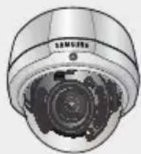
High Resolution IR Small Vandal-Resistant Dome Camera
User Manual
SCV-2081R

text_image
SAMSUNGCE


High Resolution IR Small Vandal-Resistant Dome Camera User Manual

Copyright
©2010 Samsung Techwin Co., Ltd. All rights reserved.
Trademark
SAMSUNG TECHWIN

is the registered logo of Samsung Techwin Co., Ltd.
The name of this product is the registered trademark of Samsung Techwin Co., Ltd.
Other trademarks mentioned in this manual are the registered trademark of their respective company.
Restriction
Samsung Techwin Co., Ltd shall reserve the copyright of this document. Under no circumstances, this document shall be reproduced, distributed or changed, partially or wholly, without formal authorization of Samsung Techwin.
Disclaimer
Samsung Techwin makes the best to verify the integrity and correctness of the contents in this document, but no formal guarantee shall be provided. Use of this document and the subsequent results shall be entirely on the user's own responsibility. Samsung Techwin reserves the right to change the contents of this document without prior notice.
Warranty
If the product does not operate properly in normal conditions, please let us know. Samsung Techwin will resolve the problem for free of charge. The warranty period is 3 years. However, the followings are excluded:
- If the system behaves abnormally because you run a program irrelevant to the system operation.
• Deteriorated performance or natural worn-out in process of time


Before operating the camera, confirm the camera model and correct input power voltage. To help you understand this manual thoroughly, we'll introduce our model description.
■ SCV-2081R SERIES
- NTSC MODEL
SCV-2081RN
- PAL MODEL
SCV-2081RP
■ MODEL DESCRIPTION
- SCV-2081RX
-SIGNAL SYSTEM
- SIGNAL SYSTEM
N → NTSC MODEL
P → PAL MODEL


safety information
CAUTION
RISK OF ELECTRIC SHOCK. DO NOT OPEN

CAUTION:
TO REDUCE THE RISK OF ELECTRIC SHOCK, DO NOT REMOVE COVER (OR BACK) NO USER SERVICEABLE PARTS INSIDE. REFER SERVICING TO QUALIFIED SERVICE PERSONNEL.
This symbol indicates that dangerous voltage consisting a risk of electric shock is present within this unit.

This exclamation point symbol is intended to alert the user to the presence of important operating and maintenance (servicing) instructions in the literature accompanying the appliance.
WARNING
- To prevent damage which may result in fire or electric shock hazard, do not expose this appliance to rain or moisture.
- To prevent injury, this apparatus must be securely attached to the floor/wall in accordance with the installation instructions.
WARNING
- Be sure to use only the standard adapter that is specified in the specification sheet. Using any other adapter could cause fire, electrical shock, or damage to the product.
- Incorrectly connecting the power supply or replacing battery may cause explosion, fire, electric shock, or damage to the product.
- Do not connect multiple cameras to a single adapter. Exceeding the capacity may cause abnormal heat generation or fire.
- Securely plug the power cord into the power receptacle. insecure connection may cause fire.
- When installing the camera, fasten it securely and firmly. The fall of camera may cause personal injury.
4\_ safety information


- Do not place conductive objects (e.g. screwdrivers, coins, metal parts, etc.) or containers filled with water on top of the camera. doing so may cause personal injury due to fire, electric shock, or falling objects.
- If any unusual smells or smoke come from the unit, stop using the product. in such case, immediately disconnect the power source and contact the service center. continued use in such a condition may cause fire or electric shock.
- If this product fails to operate normally, contact the nearest service center. never disassemble or modify this product in any way. (samsung is not liable for problems caused by unauthorized modifications or attempted repair.)
- When cleaning, do not spray water directly onto parts of the product. doing so may cause fire or electric shock.
CAUTION
- Do not drop objects on the product or apply strong shock to it. Keep away from a location subject to excessive vibration or magnetic interference.
- Do not install in a location subject to high temperature (over 50^ C), low temperature (below -10^ C), or high humidity. Doing so may cause fire or electric shock.
- If you want to relocate the already installed product, be sure to turn off the power and then move or reinstall it.
- Remove the power plug from the outlet when then there is a lightning. Neglecting to do so may cause fire or damage to the product.
- Keep out of direct sunlight and heat radiation sources. It may cause fire.
- Install it in a place with good ventilation.
- Avoid aiming the camera directly towards extremely bright objects such as sun, as this may damage the CCD image sensor.
- Apparatus shall not be exposed to dripping or splashing and no objects filled with liquids, such as vases, shall be placed on the apparatus.
- The Mains plug is used as a disconnect device and shall stay readily operable at any time.
- Do not expose the camera to radioactivity. Radioactivity exposure may damage the CCD.

English_5

safety information
FCC STATEMENT
This device complies with part 15 of the FCC Rules. Operation is subject to the following two conditions :
1) This device may not cause harmful interference, and
2) This device must accept any interference received including interference that may cause undesired operation.
CAUTION
This equipment has been tested and found to comply with the limits for a Class A digital device, pursuant to part 15 of FCC Rules. These limits are designed to provide reasonable protection against harmful interference when the equipment is operated in a commercial environment.
This equipment generates, uses, and can radiate radio frequency energy and, if not installed and used in accordance with the instruction manual, may cause harmful interference to radio communications. Operation of this equipment in a residential area is likely to cause harmful interference in which case the user will be required to correct the interference at his own expense.


IC Compliance Notice
This Class A digital apparatus meets all requirements of the Canadian Interference.-Causing Equipment Regulations of ICES-003.

Correct Disposal of This Product (Waste Electrical & Electronic Equipment)
(Applicable in the European Union and other European countries with separate collection systems)
This marking on the product, accessories or literature indicates that the product and its electronic accessories (e.g. charger, headset, USB cable) should not be disposed of with other household waste at the end of their working life. To prevent possible harm to the environment or human health from uncontrolled waste disposal, please separate these items from other types of waste and recycle them responsibly to promote the sustainable reuse of material resources.
Household users should contact either the retailer where they purchased this product, or their local government office, for details of where and how they can take these items for environmentally safe recycling.
Business users should contact their supplier and check the terms and conditions of the purchase contract. This product and its electronic accessories should not be mixed with other commercial wastes for disposal.

Correct disposal of batteries in this product
(Applicable in the European Union and other European countries with separate battery return systems.)
This marking on the battery, manual or packaging indicates that the batteries in this product should not be disposed of with other household waste at the end of their working life. Where marked, the chemical symbols Hg, Cd or Pb indicate that the battery contains mercury, cadmium or lead above the reference levels in EC Directive 2006/66. If batteries are not properly disposed of, these substances can cause harm to human health or the environment.
To protect natural resources and to promote material reuse, please separate batteries from other types of waste and recycle them through your local, free battery return system.
6\_ safety information


important safety instructions
- Read these instructions.
- Keep these instructions.
- Heed all warnings.
- Follow all instructions.
- Do not use this apparatus near water.
-
Clean only with dry cloth.
-
Do not block any ventilation openings. Install in accordance with the manufacturer's instructions.
-
Do not install near any heat sources such as radiators, heat registers, or other apparatus (including amplifiers) that produce heat.
-
Do not defeat the safety purpose of the polarized or grounding-type plug. A polarized plug has two blades with one wider than the other. A grounding type plug has two blades and a third grounding prong. The wide blade or the third prong is provided for your safety. If the provided plug does not fit into your outlet, consult an electrician for replacement of the obsolete outlet.
-
Protect the power cord from being walked on or pinched particularly at plugs, convenience receptacles, and the point where they exit from the apparatus.
-
Only use attachments/accessories specified by the manufacturer.
-
Use only with cart, stand, tripod, bracket, or table specified by the manufacturer, or sold with the apparatus.
-
Unplug this apparatus when a card is used. Use caution when moving the cart/ apparatus combination to avoid injury from tip-over.
-
Refer all servicing to qualified service personnel. Servicing is required when the apparatus has been damaged in any way, such as powersupply cord or plug is damaged, liquid has been spilled or objects have fallen into the apparatus, the apparatus has been exposed to rain or moisture, does not operate normally, or has been dropped.

Apparatus shall not be exposed to dripping or splashing and no objects filled with liquids, such as vases, shall be placed on the apparatus
English_7


contents
INTRODUCTION

9 Features
10 What's included
11 Component names and Functions
INSTALLATION
12
12 Installation
14 Adjust the panning and tilting while watching the monitor
CONNeCTION
15
15 Connecting to Monitor
15 Connecting to Power
16 Using Coaxial Communications
SeTUp
17
17 Menu Configratio n
17 Menu Setu p
TROUbleSHOOTING
30
30 Troubleshooting
SpeClfICATIONS
31
31 Specification s
33 Dimensio n
8_ contents


FEATURES
• IP66 Approved/Dust and Rain Resistant
With dust and rain resistant design, the camera can be installed outside under building eaves or places that are exposed to the dust and rain.
• Excellent Sensitivity
The Built-in high sensitivity COLOR CCD enables a clear image even in 0Lux(B/W,IR-LED ON) or lower illumination,
- Ultra High Resolution
By adopting a diagonal 6mm(1/3") 410,000 (NTSC) pixels, 470,000(PAL) pixels SONY CCD, the camera produces clear picture quality with a horizontal resolution of 600 TV lines for color and 700 TV lines for BW
• SSNR3 (Samsung Super Noise Reduction) Function
The high-performance W-V DSP chip effectively removes low-light gain noise and afterimage to provide clear images even in dark environments.
• Day & Night
The camera identifies whether it is day or night and automatically switches to the appropriate mode, depending on its environment. By day, the camera switches to color mode in order to maintain optimal color. At night, it switches to B/W mode so as to obtain better picture definition.
- IR MODE Function
Adjusting the intensity of IR-LEDs depends upon the closeness of the object, which in order to prevent saturation.
• DIS (Digital Image Stabilizer)
The DIS function compensates for any camera movement, to produce more stable pictures.
• Indoor Visibility range 20M
In B/W mode, the IR-LEDs are illuminated, the indoor visibility range at 0 Lux is 20M
• SSDR(Samsung Super Dynamic Range)
For images with high contrast between bright and dark areas from difficult lighting conditions such as backlighting, this camera selectively illuminates darker areas while retaining the same light level for brighter areas to even out the overall brightness.
- OSD
The camera control is convenient by using 17 different foreign language O.S.D.
- NTSC : English, Japanese, Spanish, French, Portuguese, Korean
- PAL : English, French, German, Spanish, Italian, Chinese, Russian, Polish, Czech, Romanian, Serbian, Swedish, Danish, Turkish, Portuguese
• Miscellaneous Functions
HLC(High Light Compensation), SENS-UP, FLIP (H/V-REV), D-ZOOM, SHARPNESS, Motion Dection and PRIVACY functions are provided.
English_9


introduction
WHAT'S INCIUDeD
Check if the following items are included in the product package.
natural_image
Top-down view of a surveillance camera with visible lens and central aperture (no text or symbols)
text_image
High Resolution IR Small Vandal-Resistant Dome Camera John Macau SAMSUNG
SCV-2081R User Manual Quick Set-up Guide


M4 Tapping Screw 3EA Video Output Cable
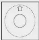
Template
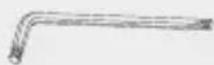
Wrench
10_ introduction


COMPONENT NAMES AND FUNCTIONS
FRONT
text_image
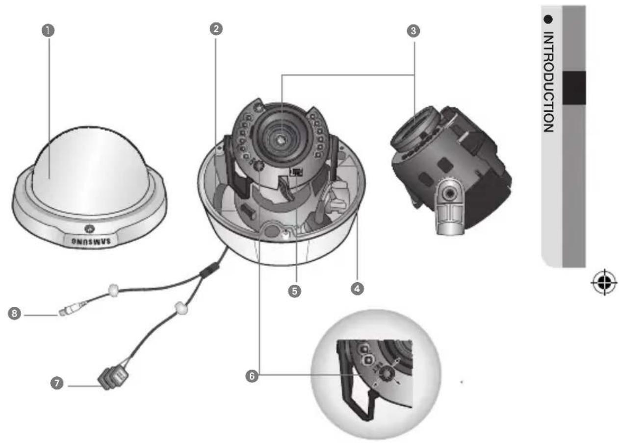
1 2 3 4 5 6 7 8 ONOSINUS INTRODUCTION① Dome Cover
② Pan Base : control panning angle of camera
3 3.6 Vari-focal Lens Module 2.8 \~ 10.0mm (F1.2)
4 Tilt Base : control tilting angle of camera
⑤ Video Output Terminal to Monitor
⑥ Function Setup Switch : displays the OSD menu and moves the cursor up, down, left, and right amend or confirm changes.
7 Power Input Connector
8 Video Output Jack
English_11
installation
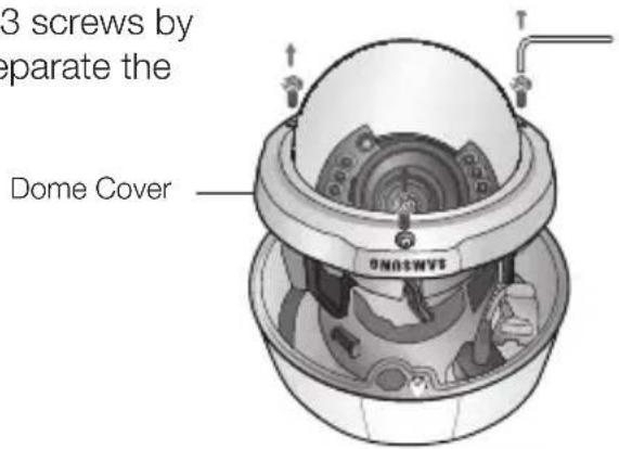
DISASSEMBLING
Using the L-wrench provided, loosen 3 screws by turning them counterclockwise and separate the dome cover.
text_image
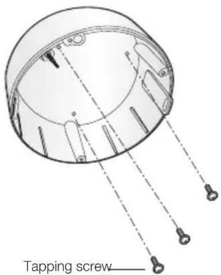
3 screws by separate the Dome CoverINSTALLING THE CAMERA ON A CEILING OR WALL
- Drill holes on the ceiling by matching to the holes on the case bed, and insert plastic anchors (HUD 5) (not included) fully into the holes. Fix the case bed on the ceiling by using Tapping Screws (TH M4xL30). (3 places)
text_image
Tapping screw12_ installation
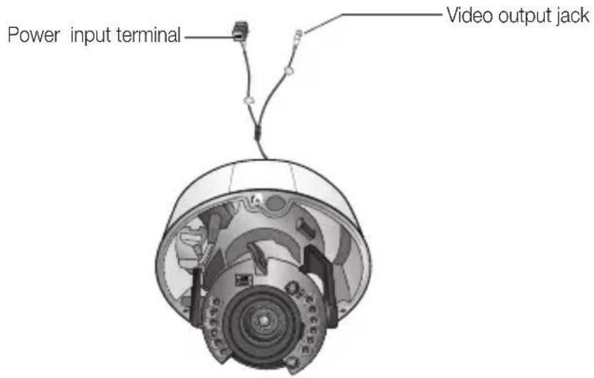
- Connect power and video cables and arrange them through the hole you want to pass when mounting the main body on the mounting bracket, note that not to damage or squeeze the cables.
text_image
Power input terminal Video output jack
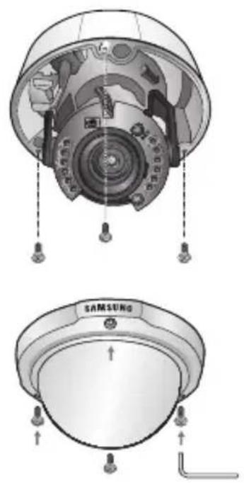
text_image
INSTALLATION- Secure the camera on its mounting bracket with the three screws using L Wrench(included).
natural_image
Technical diagram of a Samsung helmet showing internal components and mounting points (no text or symbols present)English_13


installation
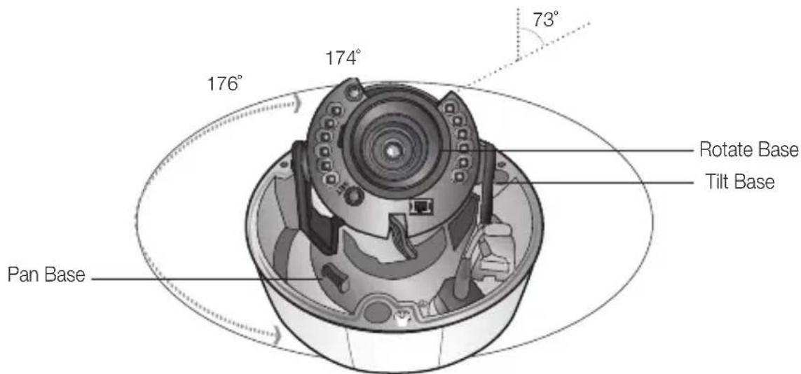
ADJUST THE pANNING, TIITING & ROTATION WHILE WATCHING THE mONITOR
text_image
73° 176° 174° Rotate Base Tilt Base Pan Base-
You can adjust camera to any direction by using Pan, Tilt, Rotate mechanism.
-
Pan Base moves by 176^ to each side direction and 352^ on the whole.
- Tilt Base covers total 73^ angle (0^ 73^) .
-
Rotate Base moves by 174^ to each side direction and 348^ on the whole.
-
Methods of adjustment
• The case of wall installation
① After mounting the camera on a wall, adjust the panning angle so that the correct viewing angle is attained and the titling is correctly orientated.
② And then adjust the tilting angle by rotating the tilt base.
3 Loosen the rotate base hold screw and adjust rotate base for the best view
④ Tighten rotate base securing screw.
• The case of ceiling installation
① After mounting the camera on a ceiling, adjusting the panning angle to the correct viewing position by rotating the pan base.
② And then adjust the tilting angle by rotating the tilt base.
3 Loosen the rotate base hold screw and adjust rotate base for the best view
④ Tighten pan and tilt securing screw.

- When you want to adjust the Pan/Tilt/Rotate Base, loosen, adjust and then tighten the Pan/Tilt/Rotate Base screws.
14\_ installation


connection
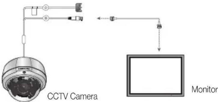
CONNeCTING TO mONITOR
Connect the VIDEO-OUT jack to the VIDEO-IN jack of monitor.
text_image
CCTV Camera Monitor- As the connecting method varies with the instruments, refer to the manual supplied with the instrument.
- Only connect the cable when the power is turned off.
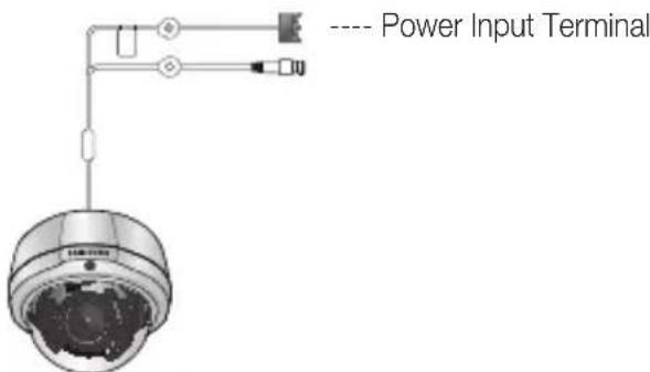
CONNeCTING TO pOWeR
Connect the adaptor to the power input connector as shown in the figure below. The recommended adaptor specification for SCV-2081RN/P is DC 12V / 500mA or AC 24V / 300mA.
text_image
---- Power Input TerminalWhen the resistance value of copper wire is at [20°C(68°F)]
| Copper wire size (AWG) | #24(0.22mm ^2 ) | #22(0.33mm ^2 ) | #20(0.52mm ^2 ) | #18(0.83mm ^2 ) |
| Resistance Ω/m) | 0.078 0.050 0.030 0.018 | |||
| Voltage Drop (V/m) | 0.028 0.018 0.011 0.006 |
- As shown in the table above, voltage decreases as the wire gets longer. Therefore use of an excessively long adaptor output line for connection to the camera may affect the performance of the camera.
English_15


text_image
CONNECTION
connection
* Standard voltage for camera operation : DC 12V ±10%, AC 24V ± 10%
* There may be some deviation in voltage drop depending on the type of wire and the manufacturer.

- Be sure to connect power only after all the installation is complete.
Note that DC adaptor is not supplied with camera.
■ Ground should be connected to the GND terminal.
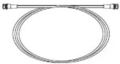
USING COAXIAI COmmUNICATIONS
• Coaxial Communications System
- OSD Control method
The camera's video output port is connected to the monitor with a BNC coaxial cable, shown below: If the distance between the camera and the monitor exceeds the recommended maximum, please use an auxiliary video amp.
natural_image
Pure diagram of a coiled cable or hose with connectors, no text or symbols present| Distance Recommended Cable Specification | |
| 300m | 3C2V(RG-59/U) |
| 450m | 5C2V(RG-6/U) |
| 600m | 7C2V(RG-11/U) |

If the camera is controlled through coaxial communication, please use a video amp intended for coaxial communications. Regular video amps do not transfer coaxial signals.
16 connection


setup
MENU CONFIGURATION
| Setup Menu | |||
| LENS | ● DC | ||
| EXPOSURE | ● BRIGHTNESS● SENS-UP | ● SHUTTER● RETURN | ● AGC |
| WHITE BALANCE | ● ATW● MANUAL | ● OUTDOOR● AWC→SET | ● INDOOR |
| SSDR | ● OFF | ● ON | |
| BACKLIGHT | ● OFF | ● BLC | ● HLC |
| SSNR3 | ● ON | ● OFF | |
| DAY/NIGHT | ● AUTO | ● COLOR | ● B/W |
| SPECIAL | ● IMAGE ADJ● MOTION DET● LANGUAGE | ● MONITOR● PRIVACY● RETURN | ● CAM TITLE● DIS |
| EXIT | ● SAVE | ● NOT SAVE | ● RESET |

text_image
SETUPMENU SETUP
Use the Function Setup switch beside of the lens.
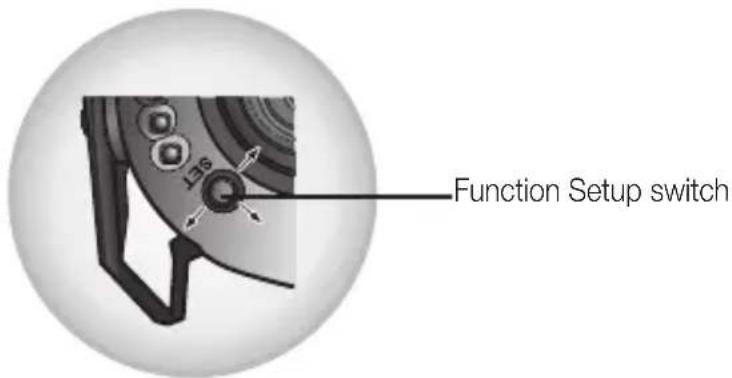
text_image
Function Setup switch- Press the Function Setup switch.
- Main setup menu is displayed on the monitor screen.
English_17
setup
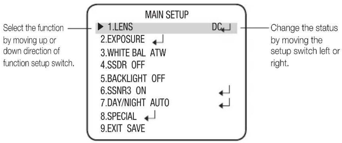
text_image
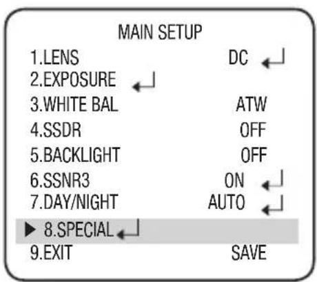
MAIN SETUP ▶ 1.LENS DC Select the function by moving up or down direction of function setup switch. 2.EXPOSURE 3.WHITE BAL ATW 4.SSDR OFF 5.BACKLIGHT OFF 6.SSNR3 ON 7.DAY/NIGHT AUTO 8.SPECIAL 9.EXIT SAVE Change the status by moving the setup switch left or right.- Select a desired function using the Function Setup switch.
- Place the cursor over a desired item.
-
Set up a selected item by using the Function Setup switch.
-
To finish the setting, select 'EXIT' and press the Function Setup switch.
An item with the icon also has sub menus. To select a sub menu, select an item with the icon and press the Function Setup switch.
■ An item with the - - - icon is unavailable due to function settings.

leNS
Using this function, you can control the screen brightness.
- When the SETUP menu screen is displayed, select 'LENS' by using the Function Setup switch so that the arrow indicates 'LENS'.
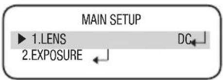
text_image
MAIN SETUP ► 1.LENS DC 2.EXPOSURE-
The Lens mode has sub menu site as listed below.
-
BRIGHTNESS : Adjusts the video brightness.
- FOCUS ADJ : To adjust the lens focus correctly, you must activate the Focus Settings mode. To activate the Focus Settings mode, adjust the lens focus, and then deactivate the settings mode.
- You can adjust the shutter value of ESC shutter mode.
18\_ setup


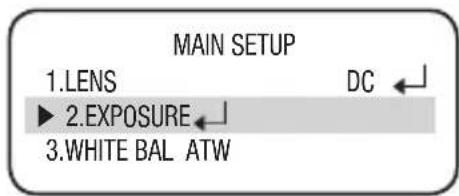
eXpOSURe
-
When the SETUP menu screen is displayed, select EXPOSURE by using the Function Setup switch so that the arrow indicates 'EXPOSURE'.
-
Select a desired mode using the Function Setup switch.
• bRIGHTNeSS : Adjusts the video brightness.
- SHUTTeR: You can select shutter mode.
- ESC : Select this to control the shutter speed automatically. If ESC is selected, the shutter speed is automatically controlled depending on the ambient illumination of the subject.
text_image
MAIN SETUP 1.LENS DC ← ► 2.EXPOSURE ← 3.WHITE BAL ATW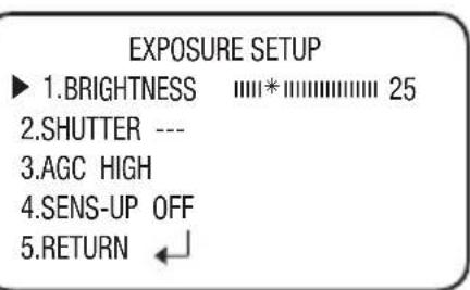
text_image
EXPOSURE SETUP ► 1.BRIGHTNESS 25 2.SHUTTER --- 3.AGC HIGH 4.SENS-UP OFF 5.RETURN ←
text_image
SETUp- MANUAL : You can control shutter speed manually. (NTSC MODEL : 1/60\~1/120,000, PAL MODEL : 1/50\~1/120,000)
- A.FLK: Select this when you experience picture flicker, this happens when there is a clash with the installed lighting frequency.
- ---: Shutter speed is fixed at 1/60sec(1/50sec).

- When the SHUTTER is set to ESC after selecting the Internal Synchronization Type, the picture may become unstable if the camera faces a bright fluorescent light. Therefore, take care when choosing the installation position.
- When the SHUTTER is set to MANUAL or A.FLK mode, SENS-UP will be disabled.
- Set the shutter mode to --- if color rolling occurs.
- AGC (AUTO GAIN CONTROL) The higher the gain level, the brighter the screen but the higher the noise.
- OFF: Deactivates the AGC function.
- LOW : Allows automatic gain control from 5.3dB to 32dB.
- HIGH : Allows automatic gain control from 5.3dB to 37dB.
English_19

setup
- SeNS-Up: When it is night or dark, the camera automatically detects the light level and maintains a clear picture if this mode is activated.
- OFF : Deactivates the SENS-UP function.
- AUTO : Activates the SENS-UP function.
text_image
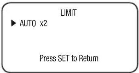
LIMIT ► AUTO x2 Press SET to Return- ReTURN: Select this to save the changes in the EXPOSURE menu and return to the SETUP menu.

If you set the Function Setup switch to 'AUTO' mode, You can adjust the brightness by increasing or decreasing the shutter speed. (x2 \~ x512)
Note that the higher the SENS-UP level, the brighter the screen, but the more likely it is that an after-image will appear.
Although Noise, Spots, and Whitish symptoms may occur in SENS-UP operation when the sens-up level is increased, this is normal.
WHITe bAI (WHITe bAIA nCe)
Use the White Balance function to adjust the screen color.
-
When the SETUP menu screen is displayed, select 'White Bal.' by using the Function Setup switch so that the arrow indicates 'White Bal.'.
-
Select a desired mode using the Function Setup switch.
text_image
MAIN SETUP 1.LENS 2.EXPOSURE 3.WHITE BAL ATW 4.SSDR OFF DC ←※ Select one of the following 5 modes, as appropriate for your purpose.
- ATW: Select this when the color temperature is between 1,700°K and 11,000°K.
-
OUTDOOR: Select this when the color temperature is between 1,700°K and 11,000°K.(sodium light inclusion) Select this When the color temperature of environment surrounding the subject is out of the control range (e.g. clear sky, or sunset)
-
INDOOR Select this when the color temperature is between 4,500°K and 8,500°K.
- mANUAI : Select this to fine-tune White Balance manually. Set White Balance first by using the ATW

text_image
WB MANUAL ▶ RGAIN 529 BGAIN 532 Press SET to ReturnPress SET to Return
20_ setup


Balance and then press the Function Setup switch.
- AWC→SeT: To find the optimal luminance level for the current environment, point the camera towards a sheet of white paper and press the Function Setup switch. If the environment changes, readjust it.

- White Balance may not work properly under the following conditions. In this case select the AWC mode.
① When the color temperature of the environment surrounding the subject is out of the control range (e.g. clear sky or sunset).
② When the ambient illumination of the subject is dim.
3 If the camera is directed towards a fluorescent light or is installed in a place where illumination changes dramatically, the White Balance operation may become unstable.
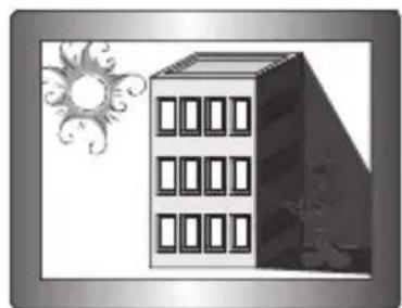
SSDR (SAmSUNG SUpeR DyNAmIC RANGe)
SSDR illuminates darker areas of an image while retaining the same light level for brighter areas to even out the overall brightness of images with high contrast between bright and dark areas.
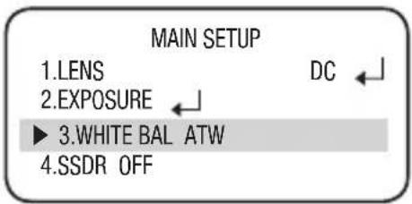
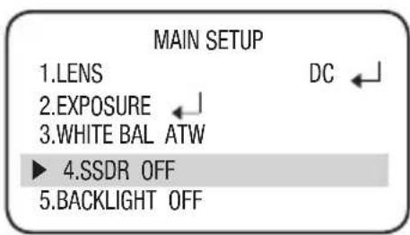
- When the SETUP menu screen is displayed, select 'SSDR' by using the Function Setup switch so that the arrow indicates 'SSDR'.
- Use the Function Setup switch to change the SSDR level in the sub menu according to the contrast between bright and dark areas.
text_image
MAIN SETUP 1.LENS 2.EXPOSURE 3.WHITE BAL ATW ► 4.SSDR OFF 5.BACKLIGHT OFF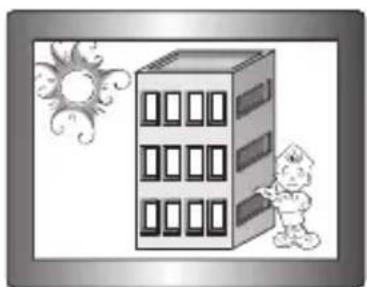
natural_image
Illustration of a cartoon building with a child standing beside it, under a sun and swirls (no text or symbols)SSDR ON
natural_image
Illustration of a modern multi-story building with windows and a sun symbol beside it (no text or symbols present)SSDR OFF
English_21


bACKIIGHT
This camera is designed so that it delivers a distinctive subject and background at the same time, even when the subject is in backlight, unlike conventional cameras, by adopting a proprietary W-V DSP chip.
- When the SETUP menu screen is displayed, select 'BACKLIGHT' by using the Function Setup switch so that the arrow indicates BACKLIGHT.
-
Select a desired mode using the Function Setup switch depending on the camera purpose.
-
bIC : Enables a user to directly select a desired area from a picture, and to view the area more clearly.
- LEVEL : Adjust level of the BLC function.
- TOP/BOTTOM/LEFT/RIGHT : Adjust the area to be enhanced.

text_image
MAIN SETUP 1.LENS DC ← 2.EXPOSURE ← 3.WHITE BAL ATW 4.SSDR OFF ► 5.BACKLIGHT OFF 6.SSNR3 ON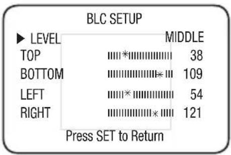
text_image
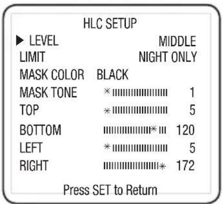
BLC SETUP ► LEVEL MIDDLE TOP 38 BOTTOM 109 LEFT 54 RIGHT 121 Press SET to Return• HIC (High light Compensation):
This function masks the strong light to minimize white out due to over exposure
and preserve much of the on-screen details when the camera aims a strong light source.
- LEVEL : Adjusts the brightness level of a monitoring area.
- LIMIT : Enable to change the operating condition.
- MASK COLOR/TONE : Change the color / brightness of the masking area. (Black, Red, Blue, Cyan, Magenta)
- TOP/BOTTOM/LEFT/RIGHT : Adjust the area to be enhanced.
text_image
HLC SETUP ► LEVEL MIDDLE LIMIT NIGHT ONLY MASK COLOR BLACK MASK TONE * 1 TOP * 5 BOTTOM 120 LEFT * 5 RIGHT 172 Press SET to Return- Off : Not being used
- Select a desired mode using the Function Setup switch and press the switch.

Because there can be a difference in the effectiveness of HLC according to the amount of light area in the screen, optimize the installation angle for the best HLC performance.
22\_ setup


In a dark environment, the HLC is only activated when a high light that is larger than a certain area is present.
■ The HLC is not activated in light or overly dark conditions. (In NIGHT ONLY mode.)
- When HLC Function is used, D-ZOOM and DIS function are not activated.
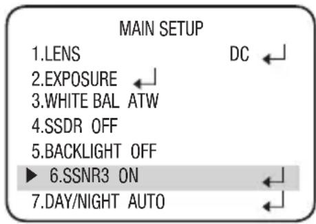
SSNR3
This function reduces the background noise in a low luminance environments.
- When the SETUP menu screen is displayed, select 'SSNR3' by using the Function Setup switch so that the arrow indicates 'SSNR3'.
-
Select a desired mode using the Function Setup switch.
-
Off : Deactivates SSNR3 so that noise is not reduced.
-
ON : Activates SSNR3 so that noise is reduced.
-
Set the SSNR3 mode to 'ON' and press the Function Setup switch. Then you can adjust the noise reduction level.
text_image
MAIN SETUP 1.LENS DC ← 2.EXPOSURE ← 3.WHITE BAL ATW 4.SSDR OFF 5.BACKLIGHT OFF ► 6.SSNR3 ON ← 7.DAY/NIGHT AUTO ←
text_image
SeTUp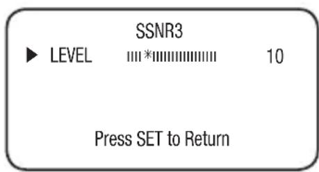
text_image
SSNR3 ► LEVEL 10 Press SET to Return

- You cannot set the SSNR3 to 'ON' or 'OFF' when the AGC mode of the EXPOSURE menu is 'OFF'.
- When adjusting the noise reduction level of the SSNR3 mode, remember that the higher the level set, the more the noise level will be reduced but that after image may also occur.
English_23


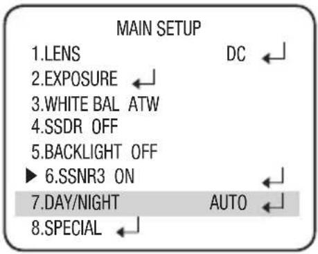
DAy/NIGHT
You can display pictures in color or black and white.
- When the SETUP menu screen is displayed, select 'DAY/NIGHT' by using the Up and Down buttons so that the arrow indicates 'DAY/NIGHT'.
- Select a desired mode using the Left and Right buttons according to the picture display you want.
• COIOR: The picture is always displayed in color.
- b/W : The picture is always displayed in black and white.
You can turn on or off the burst signal on B/W mode.
- IR LED Mode: On: 12EA, Off: 6EA
- IR MODE : When IR LED is turned on in B/W, the objects can be clearly identified due to the function that decreases screen saturation of objects within a short distance.
- AUTO: The mode is switched to "Color" in a normal environment, but switches to "B/W" mode when ambient illumination is low. To set up the switching time for AUTO mode, press the Function Setup switch.
- BURST MODE : You can turn on or off the burst signal on B/W mode.
- DWELL TIME : You can select the duration time about changing the day/night mode.
→3s, 5s, 7s, 10s, 15s, 20s, 30s, 40s, 60s
- DURATION : You can select the brightness level at which the camera switches from day to night mode.
text_image
MAIN SETUP 1.LENS DC ← 2.EXPOSURE ← 3.WHITE BAL ATW 4.SSDR OFF 5.BACKLIGHT OFF ► 6.SSNR3 ON ← 7.DAY/NIGHT AUTO ← 8.SPECIAL ←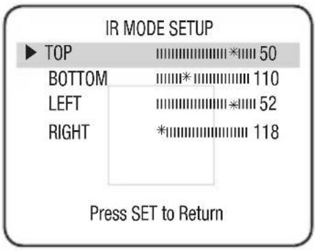
text_image
IR MODE SETUP TOP 50 BOTTOM 110 LEFT 52 RIGHT 118 Press SET to Return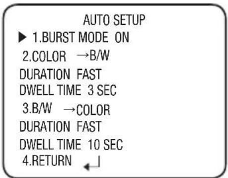
text_image
AUTO SETUP ► 1.BURST MODE ON 2.COLOR →B/W DURATION FAST DWELL TIME 3 SEC 3.B/W →COLOR DURATION FAST DWELL TIME 10 SEC 4.RETURN ←↓24_ setup


| Color → B/W B/W → Color | ||
| Fast 2.5 lux | 5 lux | |
| Slow 1 lux | 10 lux |
※ Light levels are often site dependant.

When AGC in the EXPOSURE menu is 'OFF', '---' mode operates as selecting 'COLOR' mode and 'AUTO' mode cannot be selected.
The OSD key does not work for 3 seconds when switching to Color or B/W, to ensure stable camera operation.
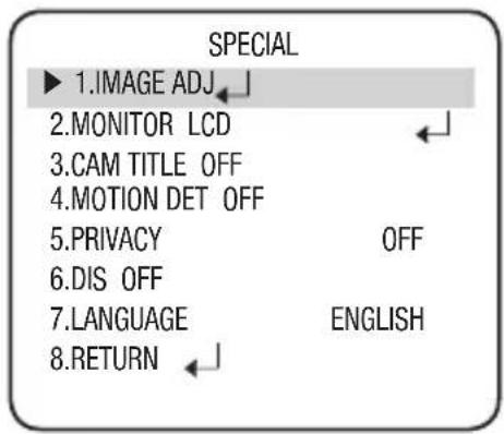
SpeCIAI
- When the SETUP menu screen is displayed, select 'SPECIAL' by using the Function Setup switch so that the arrow indicates 'SPECIAL'.
text_image
MAIN SETUP 1.LENS DC 2.EXPOSURE 3.WHITE BAL ATW 4.SSDR OFF 5.BACKLIGHT OFF 6.SSNR3 ON 7.DAY/NIGHT AUTO ▶ 8.SPECIAL 9.EXIT SAVE- Select a desired mode using the Function Setup switch.
text_image
SPECIAL ▶ 1.IMAGE ADJ 2.MONITOR LCD 3.CAM TITLE OFF 4.MOTION DET OFF 5.PRIVACY OFF 6.DIS OFF 7.LANGUAGE ENGLISH 8.RETURNEnglish_25

text_image
Setup ●setup
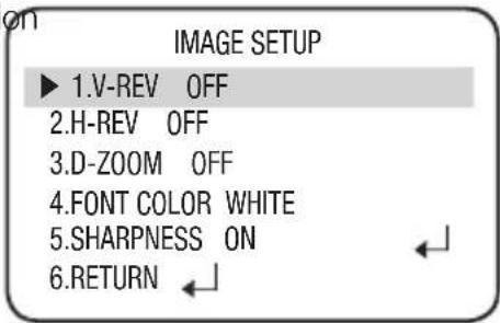
- ImAGe ADJ :
1) When the SPECIAL menu screen is displayed, select 'IMAGE ADJ' by using the Function Setup switch so that the arrow indicates 'IMAGE ADJ'.
2) Select a desired mode using the Function Setup switch.
- V-REV : You can flip the picture vertically on the screen.
- H-REV : You can flip the picture horizontally on the screen.
- D-ZOOM : You can use a digital zoom of x1 \~ x16.
- FONT COLOR : You can change the OSD font color. (White, Yellow, Green, Red, Blue)
- SHARPNESS: As you increase this value, the picture outline becomes stronger and clearer. Adjust this value appropriately depending on the sharpness of the picture.
- RETURN : Select this to save the settings for the IMAGE ADJ menu and to return to the SPECIAL menu.
If you increase the SHARPNESS level too high, the picture may become distorted or noise may appear.
- monitor: Please change the settings value of video appropriate to your monitor.
- LCD : Please select this menu item when using an LCD monitor. You can change the gamma, PED level and color gain in the sub menus.
- CRT : Please select this menu item when using a CRT monitor.
- USER : Please use this menu item when using a monitor other than standard ones. You can change the gamma, PED level and color gain in the sub menus.
text_image
ON IMAGE SETUP ► 1.V-REV OFF 2.H-REV OFF 3.D-ZOOM OFF 4.FONT COLOR WHITE 5.SHARPNESS ON 6.RETURN ←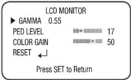
text_image
LCD MONITOR ▶ GAMMA 0.55 PED LEVEL 17 COLOR GAIN 50 RESET ← Press SET to Return26_ setup


If you increase the SHARPNESS level too high, the picture may become distorted or noise may appear.
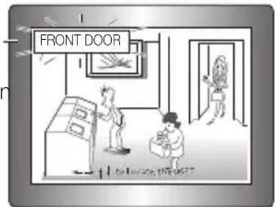
- CAm TITLE :
If you enter a title, the title will appear on the monitor.
If the SPECIAL menu screen is displayed, use the Function Setup switch so that the arrow indicates 'CAM TITLE'.
② Set it to 'ON' by using the Function Setup switch.
3 Press the Function Setup switch.
4 Use the Function Setup switch to move to a desired letter and select the letter by pressing the switch. Repeat this to enter multiple letters. You can enter up to 15 letters.
5 Enter a title, move the cursor to 'POS' and press the Function Setup switch. The - entered title appears on the screen. Select the position to display the title on the screen by using the Function Setup switch and press. When the position is determined, select 'END' and press the Function Setup switch to return to the SPECIAL menu.
a b c d e f g h i j k l m
nopqrstuvwxyz
-.0123456789
← → CLR POS END
The Ground Truth image displays a single, solid horizontal line. According to Rule 2 (UNDERSCORE & LINE RULES), if the GT contains lines used for stylistic emphasis or as background (like ruled paper), the OCR result must ignore them. The provided OCR content is "____", which consists of four underscores. This is incorrect because underscores are not equivalent to a solid line and are not permitted under the “Stylistic/Background Lines (Ignore)” rule. The OCR has hallucinated underscores where none should exist in the GT, violating the “Stylistic/Background Lines (Ignore)” rule. Therefore, the OCR result is inconsistent with the Ground Truth.
- When the CAM TITLE menu is 'OFF', no title will be displayed on the monitor screen even if you enter one.
■ Only English is available in the mode.
If you move the cursor to CLR and press the Function Setup switch, all the letters are deleted. To edit a letter, change the cursor to the bottom left arrow and press the Function Setup switch. Move the cursor over the letter to be edited, move the cursor to the letter to be inserted and then press the Function Setup switch.
CAMERA TITLE SETUP
ABCDEFGHIJKLMNOPQRSTUVWXYZ
text_image
FRONT DOOR I can be done this week
text_image
SeTUp t
English_27
setup
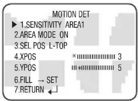
- mOTION DeT:
This product has a feature that allows you to observe movement of objects in 8 different areas on the screen, and the words 'MOTION DETECTED' appear on the screen when movement is detected. You can monitor activity more efficient.
When the SPECIAL menu screen is displayed, press the Function Setup switch so that the arrow indicates 'MOTION DET'.
② Set up the mode using the Function Setup switch.
- SENSITIVITY :
You can select up to 8 MD areas.
When SENSITIVITY number is high, motion detection sensitivity is increased to recognize even small movement.
text_image
MOTION DET ► 1.SENSITIVITY AREA1 2.AREA MODE ON 3.SEL POS L-TOP 4.XPOS ×|||||||||| 3 5.YPOS ||*|||||||||| 5 6.FILL → SET 7.RETURN ←- AREA MODE : Determines whether to use the MD area selected in SENSITIVITY.
- SEL POS : Determines which of the 4 vertices of each MD area is to be used.
- XPOS : Determines the coordinate of the horizontal axis for SEL POS.
- YPOS : Determines the coordinate of the vertical axis for SEL POS.
- FILL → SET : Fills in a selected MD area. The color of filling is sequentially selected as brown, orange, blue, cyan, yellowish green, yellow, magenta and red.
- RETURN : Select this to save the MOTION DET menu settings and return to the SPECIAL menu.

MD areas show only MOTION DET menu. Therefore, MD areas don't display on the monitor screen.
- pRIVACy: Mask an area you want to hide on the screen,
When the SPECIAL menu screen is displayed, press the Function Setup switch so that the arrow indicates 'PRIVACY'.
② Set up the mode using the Function Setup switch.
- AREA SEL : You can select up to 12 PRIVACY areas.
- MODE : Determines whether to use the area selected in the AREA SEL, and the size and position of the area.
28_ setup


- MASK COLOR : Determine area color. You can select GREEN, RED, BLUE, BLACK, WHITE and GRAY.
- MASK TONE : Adjust the brightness of MASK COLOR.
- TOP/BOTTOM/LEFT/RIGHT : Adjust the size and position of the selected area.
- RETURN: Select this to save the PRIVACY menu settings and return to the SPECIAL menu.
PRIVACY AREA SETUP
▶ 1.AREA AREA1
2.MODE OFF
3.MASK COLOR GREEN
4.MASK TONE *1
5.TOP 39
6.BOTTOM 79
7.LEFT *13
8.RIGHT 52
9.RETURN
• DIS (Digital Image Stabilizer)
This function mitigates any picture movement due to external factors such as wind.

As the DIS function uses the digital zoom the camera's resolution will decrease.
- DIS doesn't operate when background illumination is too low.
DIS doesn't operate when object pattern is monotonic as like sky or white wall.
If DIS is enabled, the digital zoom is not configured to less than x1.2 level.
- LANGUAGE: You can select the menu language according to your requirements.
- NTSC : Korean, English, French, Spanish, Japanese, Portuguese
- PAL : English, Chinese, German, Italian, French, Spanish, Russian, Czech, Polish, Romanian, Serbian, Swedish, Danish, Turkish, Portuguese
- RETURN: Select this to save the SPECIAL menu settings and return to the MAIN SETUP menu.
EXIT
Select a desired EXIT mode using the Function Setup switch depending on the camera purpose.
- SAVE : Save the current settings and exit the MAIN SETUP menu.
- NOT SAVE: Do not save the current settings and exit the MAIN SETUP menu.
- RESET: Resets the camera settings to the factory defaults. Language and Monitor settings are not initialized.
English_29

troubleshooting
TROUbleSHOOTING
If you have trouble operating your camera, refer to the following table. If the guidelines do not enable you to solve the problem, contact an authorized technician.
| pROblem SOIUTION | |
| Nothing appears on the screen. | ▶ Check that the power cord and line connection between the camera and monitor are fixed properly. ▶ Check that you have properly connected BNC cable to the camera. |
| The image on the screen is dim. | ▶ Is the lens stained with dirt? Clean your lens with a soft, clean cloth. ▶ Check the monitor and DVR settings. ▶ If the camera is exposed to very strong light, change the camera position. |
| The image on the screen is dark. | ▶ Adjust the contrast feature of the monitor. ▶ If you have an intermediate device, set the 75Ω / Hi-z properly. |
| The camera is not working properly, and the surface of the camera is hot. | ▶ Check that you have properly connected the camera to an appropriate power source. |
| The DAY/NIGHT menu does not work. | ▶ Check that AGC of EXPOSURE SETUP menu is ‘OFF’. |
| The SENS-UP function does not work. | ▶ Check that AGC of EXPOSURE SETUP menu is ‘OFF’. ▶ Check that SHUTTER of EXPOSURE SETUP menu is ‘A.FLK’ or ‘MANUAL’. |
| The Motion Detection function does not work. | ▶ Check that MOTION DEF of SPECIAL SETUP menu is ‘OFF’. |
| Color is not correct. | ▶ Check the setting of WHITE BAL SETUP menu. |
| The screen flickers continually. | ▶ Check that the camera is not pointing at the sun. |
| When coaxial communication is not available: | ▶ Make sure that the camera and monitor are installed within the recommended distance. ▶ Use the video amplifier equivalent to coaxitron if the recommended installation distance is exceeded. |
| IR-LED isn't lighted. | ▶ Isn't DAYNIGHT function setting up the color mode? ▶ Please change the AUTO or B/W mode. |
30_ troubleshooting


specifications
SPECIFICATIONS
| SCV-2081RN SCV-2081RP | ||
| VIDEO | ||
| Imaging Device | 1/3 inch, Diagonal 6mm Super HAD CCD | |
| Total Pixels | 811(H) x 508(V) 795(H) x 596(V) | |
| Effective Pixels | 768(H) x 494(V) 752(H) x 582(V) | |
| Scanning System | 2 : 1 Interlace | |
| Synchronization | Internal | |
| Frequency | H:15.734KHz / V:59.94Hz H:15 | .625KHz / V:50Hz |
| Horizontal Resolution | Color : 600 TV lines, B/W : 700 TV lines | |
| Min. Illumination | COLOR : 0.15 Lux (50IRE, @F1.2), 0.0003Lux (SENS-UP, x512)B/W : 0.001Lux (50IRE, @F1.2, LED OFF), 0.000002Lux (SENS-UP, x512), 0Lux(LED ON) | |
| S / N Ratio | 52dB (AGC off, Weight on) | |
| Video Output | CVBS : 1.0 Vp-p / 75Ω composite | |
| Lens Type | ||
| Zoom Ratio | 3.6x (Manual) | |
| Focus Length | 2.8 ~ 10.0mm (F1.2) | |
| Angular Field of View | Tele : 28°(H) x 21°(V), Wide : 94.4°(H) x 69.2°(V) | |
| Pan / Tilt /Rotate | ||
| Pan/Tilt/Rotate Range | 0°~352° / 0°~73° / 0°~348° | |
| OPERATIONAL | ||
| On Screen Display | Multi-language Support byCoaxial CableEnglish, Japanese, Spanish, French,Portuguese, Korean | Multi-language Support byCoaxial CableEnglish, French, German, Spanish,Italian, Chinese, Russian, Polish,Czech, Romanian, Serbian, Swedish,Danish, Turkish, Portuguese |
| Camera Title | Off / On (Displayed 15 characters) | |
| Day & Night | Auto (ICR) / Color / B/W | |

English_31
specifications
| SCV-2081RN SCV-2081RP | ||
| Backlight Compensation | BLC / HLC / Off | |
| Contrast Enhancement | SSDR (Off/On) | |
| Digital Noise Reduction | SSNR III (Off / On) | |
| Digital Image Stabilization | Off / On | |
| Motion Detection | Off / On (8 programmable zones) | |
| Privacy Masking | Off / On (12 programmable zones) | |
| Sens-up (Frame Integration) | 2x ~ 512x | |
| Gain Control | Low / High / Off | |
| White Balance | ATW / Outdoor / Indoor / Manual / AWC (1,700K° ~ 11,000K°) | |
| Electronic Shutter Speed | 1/60 ~ 1/120,000 sec 1/50 ~ 1/120,000 sec | |
| Digital Zoom | Off / On (1x ~ 16x) | |
| Flip / Mirror (Reverse) | H-Rev (Off/On), V-Rev (Off/On) | |
| Communication | Coaxial Control (SPC-300, Pelco Coaxitron Compatible) | |
| IR Distance | 20m (IR LED 12 EA) | |
| Environmental | ||
| Operating Temperature / Humidity | -10°C ~ +50°C (+14°F ~ +122°F) / Less than 90% RH | |
| Electrical | ||
| Input Voltage | AC 24V ± 10%, DC 12V±10% | |
| Power Consumption | Max. 3.0W (IR LED ON: 4.0W(Max)) | |
| Mechanical | ||
| Color / Material | Body : Ivory, PC/ABS, Dome Cover : PC | |
| Dimension | ∅137 x 106mm | |
| Weight | 1.2Kg | |
※ This specification can be changed without notice for performance improvement of product.
32\_ specifications


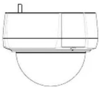
DImeNSION

text_image
R R1=0.2P/2 R2=0.2P/2 R3=0.2P/2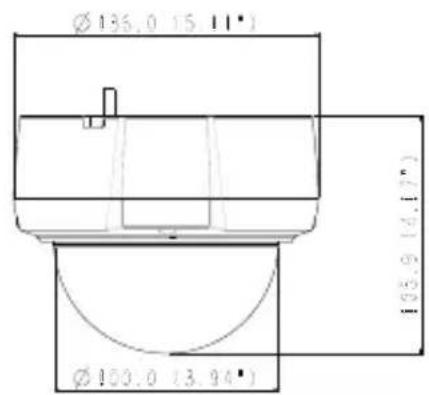
text_image
Ø136.0 15 11° Ø100.0 13.94° 14.17°Unit : mm(fueless)
natural_image
Line drawing of a toilet with a handle and lid (no text or symbols)
text_image
Specifications
natural_image
Simple circular diagram with four marked points, no text or symbols presentEnglish_33
MEMO


MEMO


SALES NETWORK
SAMSUNG TECHWIN CO., LTD.
Samsungtechwin R&D Center, 701, Sampyeong-dong, Bundang-gu, Seongnam-si, Gyeonggi-do, Korea, 463-400
TEL : +82-70-7147-8740\~60, FAX : +82-31-8018-3745
Samsung House, 1000 Hillswood Drive, Hillswood Business Park
Chertsey, Surrey, UNITED KINGDOM KT16 OPS
TEL: +44-1932-45-5300, FAX: +44-1932-45-5325
www.samsungtechwin.com
www.samsungsecurity.com
P/NO.: Z6806163501A