SCD-3080 - Surveillance Camera SAMSUNG - Free user manual and instructions
Find the device manual for free SCD-3080 SAMSUNG in PDF.

User questions about SCD-3080 SAMSUNG
0 question about this device. Answer the ones you know or ask your own.
Ask a new question about this device
Download the instructions for your Surveillance Camera in PDF format for free! Find your manual SCD-3080 - SAMSUNG and take your electronic device back in hand. On this page are published all the documents necessary for the use of your device. SCD-3080 by SAMSUNG.
USER MANUAL SCD-3080 SAMSUNG
Before installing and operating this product, please read this manual thoroughly.
Before operating the camera, confirm the camera model and correct input power voltage. To help you understand this manual thoroughly, we'll introduce our model description.
■ SUD-3080 SERIES
- NTSC MODELS
SUD-3080N
• PAL MODELS
SUD-3080P
■ MODEL DESCRIPTION
- SUD-3080X
• SIGNAL SYSTEM
N → NTSC MODEL
P → PAL MODEL

text_image
CAUTION RISK OF ELECTRIC SHOCK DO NOT OPEN CAUTION : TO REDUCE THE RISK OF ELECTRIC SHOCK, DO NOT REMOVE COVER (OR BACK), NO USER SERVICEABLE PARTS INSIDE. REFER SERVICING TO QUALIFIED SERVICE PERSONNEL.
The lightning flash with an arrowhead symbol, within an equilateral triangle is intended to alert the user to the presence of uninsulated “dangerous voltage” within the product's enclosure that may be of sufficient magnitude to constitute a risk of electric shock to persons.

The exclamation point within an equilateral triangle is intended to alert the user to the presence of important operating and maintenance (servicing) instructions in the literature accompanying the appliance.
INFORMATION - This equipment has been tested and found to comply with limits for a Class A digital device, pursuant to part 15 of the FCC Rules. These limits are designed to provide reasonable protection against harmful interference when the equipment is operated in a commercial environment. This equipment generates, uses, and can radiate radio frequency energy and, if not installed and used in accordance with the instruction manual, may cause harmful interference to radio communications.
Operation of this equipment in a residential area is likely to cause harmful interference in which case the user will be required to correct the interference at his own expense.
WARNING - Changes or modifications not expressly approved by the manufacturer could void the user's authority to operate the equipment.
WARNING - To prevent electric shock and risk of fire hazards:
◆ Do NOT use power sources other than that specified.
◆ Do NOT expose this appliance to rain or moisture.
This installation should be made by a qualified service person and should conform to all local codes.
Contents
- Features 5
- Precautions 8
- Components and Accessories 10
• Overview 10
- Installation 12
■ Installation 12
■ Adjust the panning and tilting, rotating while watching the monitor …… 14
■ Adjusting varifocal lens zoom and focus 15
■ Connecting External Cable 15
- Connection 16
System Diagram 16
■ RJ-45 Connector Schematic Diagram 18
■ Using Coaxial Communications 19
- Operating Your Camera 20
■ Menu Configuration 20
Menu Setup 2
LENS 22
EXPOSURE 22
WHITE BAL 24
BACKLIGHT 25
SSNR3 28
DAY/NIGHT 28
PROFILE 30
SPECIAL 31
EXIT 40
- Troubleshooting 41
- Specifications 42
- Dimension 44
Ultra High Resolution
By adopting a double-speed 410,000 pixel Sony CCD, the camera produces clear picture quality with a horizontal resolution of 600 TV lines for color, and 700 TV lines for B/W.
Excellent Sensitivity
The built-in high sensitivity COLOR CCD produces a
clear image. - Color: 0.3 Lux (5DIRE, @F1.2).
0.0006LUX (SENS-UP, x512)
- B/W : 0.01 Lux (50IRE, @F1.2),
0.00002 LUX (SENS-UP, x512)
Intelligence
Without assistance from an external sensor, this camera independently detects and traces objects while examining stillness and movement to activate the alarm.
SSNR3 (Samsung Super Noise Reduction) Function
The high-performance SV-V DSP chip effectively removes low-light gain noise and afterimage to provide clear images even in dark environments.
Day&Night (ICR)
This camera has a function that automatically selects the mode that is appropriate for daytime or night-time conditions.
The COLOR mode operates in daytime conditions to provide optimum colors, and B/W mode operates in nighttime conditions to enhance the definition of the image.
Features
SSDR
(Samsung Super Dynamic Range)
For images with high contrast between bright and dark areas from difficult lighting conditions such as backlighting, this camera selectively illuminates darker areas while retaining the same light level for brighter areas to even out the overall brightness.
PROFILE
You can set a mode according to the camera installation conditions. - BASIC, DAY/NIGHT, BACKLIGHT, ITS, INDOOR, USER
PIP
Displays a full-size image along with the thumbnail.
WDR
By adopting a proprietary SV-V DSP chip, the camera delivers clear, high quality pictures even in backlight, by increasing exposure in dark areas while decreasing it in bright areas; a corrected image with clear details results.
VPS(Virtual Progressive Scan)
Adopting Samsung's unique development, the VPS (Virtual Progressive Scan) enhances the sharpness of moving subject's outline. The VPS enables elective output in progressive mode using the existing interlaced input and effectively enhances the sharpness of captured pictures from video and still images. The function effectively removes blurred outline problems resulting in excellent road monitoring and improved license plate recognition.
UTP TX
One UTP cable transmits power for the camera, video signals and RS-485 data; installation is easy and clean. (TIA/EIA-568B)
Features

DIS (Digital Image Stabilizer)
The DIS function compensates for any camera movement, to produce more stable pictures.
Miscellaneous Functions
HLC(High Light Compensation), SENS-UP, REVERSE, D-ZOOM, SHARPNESS and PRIVACY functions are provided.
Communication
RS-485 and Coaxial communication methods are supported.
- RS-485 Communications : SAMSUNG-T, SAMSUNG-E, PELCO-D, PELCO-P, BOSCH, HONEYWELL, VICON, PANASONIC.
- Coaxial Communications : Pelco Coaxitron
OSD
The camera's OSD is complimented by 18 languages.
- NTSC: English, Korean, Japanese, Spanish, French, Portuguese, Taiwanese - PAL: English, Chinese, German, Italian, French, Spanish, Russian, Czech, Polish, Romanian, Serbian, Swedish, Danish, Turkish, Portuguese

Samsung Techwin cares for the environment at all product manufacturing stages to preserve the environment, and is taking a number of steps to provide customers with more environment-friendly products. The Eco mark represents Samsung Techwin's will to create environment-friendly products, and indicates that the product satisfies the EU RoHS Directive.

Warnings & Cautions
This information is provided to ensure your safety and to prevent any losses, financial or otherwise. Please read it carefully and use the product accordingly.
* For product inquiries, please contact the retail shop where you bought the camera. The use of equipment such as an aerial ladder while providing after-sales service shall be at your expense.
* Separate the power plug during a thunder storm.
* This product is support equipment for surveillance system. Therefore, we can't compensate for material loss and/or personal injuries by robbery, fire, natural disaster or other such events.
Warning/Attention/Special Mark Messages

Ignoring this information may result in material loss and/or serious personal injuries including death.

Ignoring this information may result in material loss and/or a slight injuries.

Indicates "Never Allowed."

Indicates "No Disassembling."

Correct Disposal of This Product (aste Electrical & Electronic Equipment)
(Applicable in the European Union and other European countries with separate collection systems)
This marking shown on the product or its literature, indicates that it should not be disposed with other household wastes at the end of its working life. To prevent possible harm to the environment or human health from uncontrolled waste disposal, please separate this from other types of wastes and recycle it responsibly to promote the sustainable reuse of material resources.
Household users should contact either the retailer where they purchased this product, or their local government office, for details of where and how they can take this item for environmentally safe recycling.
Business users should contact their supplier and check the terms and conditions of the purchase contract. This product should not be mixed with other commercial wastes for disposal.
Precautions

Do not install under extreme temperature conditions.

-10°C and +50°C. Provide good ventilation when using in high temperature conditions.
Do not install in high humidity environment.

May lower image quality. Use only under temperature conditions between
Do not install under unstable lighting conditions.

Severe lighting changes or flickering may hinder normal camera operation.
Avoid touching the camera lens.
The lens is the most important component of the camera. Be careful not to smear it with fingerprints.
Do not drop the camera or subject it to physical shock.

Never keep the camera face to strong light directly.

May damage the CCD. May cause a product malfunction.
Do not expose the camera to radioactivity.

If exposed to radioactivity, the OCD will fail.
Do not expose the camera to rain or other types of liquids.

May cause a product malfunction. Wipe dry any liquids. Liquids may contain minerals that are corrosive to electronic components.
When connecting cables, be sure to read the instructions carefully and follow each step as instructed.
Failure to do so may result in critical system damage.
Notes
- Exposure to a spotlight or an object emitting strong light may cause smear or blooming. - Ensure that the power source complies with normal specifications before supplying it to the camera.
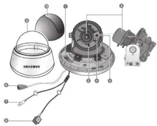
Components and Accessories

text_image
Diagram showing six labeled parts of a security camera with corresponding images and wiring, likely illustrating a surveillance or monitoring system.Super High Resolution UTP Dome Camera SUD-3080
M4 Tapping Screw 4EA M4 Machine Screw 4EA
6 Installation Video Output Cable 7 External Cable
2 Instruction Manual
⑤ Adapter plate
Overview
text_image
ONOSWVS ① ② ③ ④ ⑤ ⑥ ⑦ ⑧ ⑨ ⑩
Overview
① Pan Bracket : Control panning angle of camera.
2 Rotate Body : Control rotating angle of camera.
x3.9 Vari-focal Lens Module 2.8 \~ 11mm (F1.2)
④ Video Output Terminal to Monitor
⑤ Function Setup switch : Display the menu on the screen and move the cursor to four directions to confirm status or changing a selected item.
⑥ UTP Cable : For supplying AC 24V / AC28V power to the camera and transmitting video signals.
7 Video Output Jack : Video signals are output through this port. Connect this port to the Video IN port of a monitor.
③ Power Input Terminal : If the UTP cable cannot be connected for power supply (distance over 300m(1000ft), for example), this cable is used instead for connecting DC 12V / AC 24V power to the camera.
Dome Cover 10 Shield Case
Notes
- Be sure to connect the Day & Night input terminal to GND when using an external input.
Installation

Installation
Notes
- The installation should be done by qualified service personnel or sytem installers.
- If the ceiling material is not strong enough to hold the installation screws, the camera may fall off. Reinforce the ceiling as needed.
1) Separate the dome cover by rotating anti-clockwise.
2) Separate the shield case by pulling from the camera body.
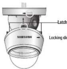
text_image
Latch SAMSUNG Locking dir[Figure-1]
* To install the dome cover on the camera body, turn the latches in locking direction as shown in the Figure-1.
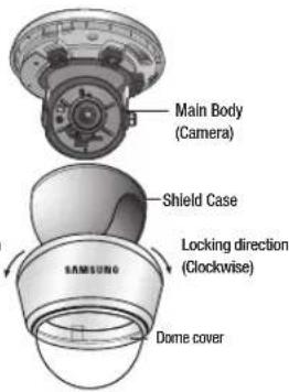
text_image
Main Body (Camera) Shield Case Locking direction (Clockwise) Dome coverWhen installing on a adapter plate
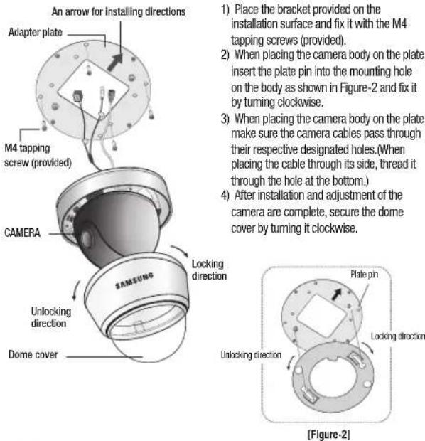
1) Place the bracket provided on the installation surface and fix it with the M4 tapping screws (provided).
2) When placing the camera body on the plate, insert the plate pin into the mounting hole on the body as shown in Figure-2 and fix it by turning clockwise.
3) When placing the camera body on the plate, make sure the camera cables pass through their respective designated holes. (When placing the cable through its side, thread it through the hole at the bottom.)
4) After installation and adjustment of the camera are complete, secure the dome cover by turning it clockwise.
Notes
- Please locate an arrow on bracket for installing direction that you wish to observe Area and then fix it with the M4 tapping screws.
Installation

Adjust the panning and tilting, rotating while watching the monitor
text_image
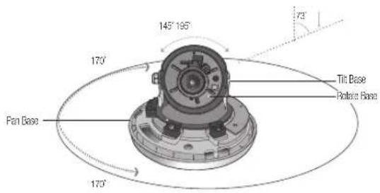
145° 195° 73° 170° Tilt Base Rotator Base Pan Base 170°1) You can adjust the camera to any direction by using Pan, Tilt, Rotate mechanism.
- Pan Bracket moves by 170^ in each direction or 340^ on the whole.
- Tilt Base covers total 73° angle(0° \~ 73°).
- The angle range of the Rotate Body is the same as that of the Pan Bracket. But one direction range is 195° and another is 145°
2) Methods of adjustment
- Mounting on a wall
After mounting the camera on a wall, adjusting the panning angle so that the camera can face the direction to monitor when tilted.
② Adjust the tilting angle by rotating the tilt base.
③ Locusen the rostate base hold screw and adjust rostate base for the best view.
4 Tighten the rotate base hold screw.
- Mounting on a ceiling
After mounting the camera on a ceiling, adjusting the panning angle to the correct viewing position by rotating the pan base.
② Adjust the filling angle by rotating the tilt base.
③ Locusen the rotate base hold screw and adjust rotate base for the best view.
4 Tighten the rotate base hold screw.
Adjusting varifocal lens zoom and focus
1) Unlock the zoom(focus) handle by turning anti-clockwise.
2) Adjust the zoom(focus) by moving the handle to WIDE(FAR) or TELE(NEAR).
3) After adjustment, tighten the zoom (or the focus) handle, taking care that the adjusted position does not change.
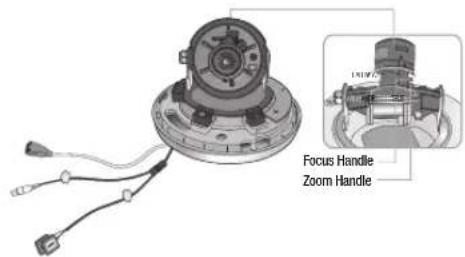
text_image
Focus Handle Zoom HandleConnecting External Cable
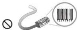
You can use the External Cable provided with camera as the following features.
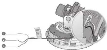
text_image
Technical diagram showing a mechanical assembly with labeled parts, including a cable and a magnified inset view.① MD Output Terminal Motion detection signals are output through this terminal.
D & N Input Terminal: You can switch to Day & Night Mode by connecting an external signal to this terminal.
3 Ground Terminal
Connection

System Diagram
UTP Power Supply Link Setup
- SUD-3080 → 4Ch Power Supply → 4Ch Receiver → DVR/Monitor/Controller The maximum power transmission distance for the camera is 300m(1000ft), and the distance between the camera and the 4ch Receiver cannot exceed 900m(3000ft).

flowchart
graph TD
    A["SUD-3080"] --> B["SPU-400"]
    B --> C["RS-485"]
    B --> D["SPU-400R"]
    D --> E["SCC-3100A"]
    B --> F["300m(1000ft) or Less"]
    D --> G["900m(3000ft) or Less"]
    H["UTP CABLE"] --> B
    I["BNC CABLE"] --> D
    J["RS-485"] --> D
    style A fill:#f9f,stroke:#333
    style B fill:#ccf,stroke:#333
    style D fill:#ccf,stroke:#333
    style E fill:#cfc,stroke:#333
    style F fill:#fcc,stroke:#333
    style G fill:#fcc,stroke:#333
    style H fill:#fff,stroke:#333
    style I fill:#fff,stroke:#333
    style J fill:#fff,stroke:#333
- UTP Receiver Link Setup(Additional Power input is needed) SUD-3080 → 1Ch Passive Receiver → DVR → Monitor
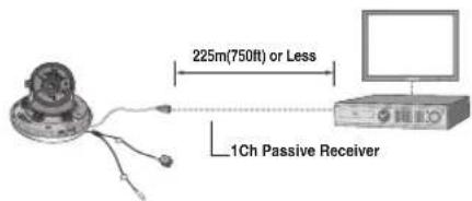
text_image
225m(750ft) or Less 1Ch Passive ReceiverNotes
- Using the product with third-party UTP peripherals may result in degradation of product function and performance.
- Attenuation and distortion in signal may occur if the maximum transmission distance is exceeded. Please note that depending on the installation environment/condition, the signal may become attenuated and distorted and cause the camera to function incorrectly even when the transmission distance is within the maximum.
- If using RS-485 communication, please use the SAMSUNG-T, SAMSUNG-E, PELCO-D, PELCO-P, BOSCH, HONEYWELL, VICON and PANASONIC Protocol.
- If you are using the 1Ch Passive Receiver system setup, please connect the adapter (AC 24V or DC 12V) directly to the camera.
UTP CABLE
The camera uses UTP cable for transmitting video signals, power and transferring RS-485 control data.(TIA/EIA-568B)
| No. Line Color Camera to Power Supply Power Supply to Receiver | ||||
| 1 White+Orange VIDEO (-) | CH1 | VIDEO (-)/RS-485 (+) | ||
| 2 Orange VIDEO (-) VIDEO (-) / RS-485 (-) | ||||
| 3 White+Green RS485 (+) | CH2 | VIDEO (-)/RS-485 (+) | ||
| 4 Blue POWER (-) VIDEO (-) / RS-485 (-) | ||||
| 5 White+Blue | POWER (+) | CH3 | VIDEO (-)/RS-485 (+) | |
| 6 Green | PS485 (-) | VIDEO (-)/RS-485 (-) | ||
| 7 White+Brown | POWER (+) | CH4 | VIDEO (-)/RS-485 (+) | |
| 8 Brown | POWER (-) VIDEO (-) / RS-485 (-) | |||
Connection

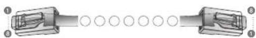
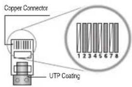
RJ-45 Connector Schematic Diagram
text_image
Copper Connector UTP Coating| No. Line Color Camera to Power Supply Power Supply to Receiver | ||||
| 1 White+Orange VIDEO (+) | CH1 | VIDEO (+)/RS-485 (-) | ||
| 2 Orange VIDEO (-) VIDEO (-) / RS-485 (-) | ||||
| 3 White+Green RS485 (+) | CH2 | VIDEO (+)/RS-485 (-) | ||
| 4 Blue POWER (-) VIDEO (-) / RS-485 (-) | ||||
| 5 White+Blue POWER (+) | CH3 | VIDEO (+)/RS-485 (-) | ||
| 6 | Green | RS485 (-) | VIDEO (-)/RS-485 (-) | |
| 7 White+Brown | POWER (+) | CH4 | VIDEO (+)/RS-485 (-) | |
| 8 | Brown | POWER (-) VIDEO (-)/RS-485 (-) | ||
The SUD-3080 uses UTP cable to receive its power (AC24V/AC28V) from the Power Supply. Therefore, a separate adapter is not required. Please refer to the RJ-45 Connector Schematic Diagram.
Using Coaxial Communications
• Coaxial Communications System
- OSD Control method
The camera's video output port is connected to the monitor with a BNC coaxial cable, shown below: If the distance between the camera and the monitor exceeds the recommended maximum, please use an auxiliary video amp.
| Distance Recommended Cable Specification | |
| 300m | 3C2V(RG-53U) |
| 450m | 5C2V(RG-6U) |
| 600m | 7C2V(RG-11U) |

Notes
- It is recommended that pure copper coax cable is used and not copper coated steel, as this will cause issues with the communication over the coaxial cable.
Operating Your Camera

Menu Configuration
| MAIN SETUP | |||
| LENS | ● DC | ||
| EXPOSURE | ● BRIGHTNESS ● SHUTTER ● SENS-UP ● RETURN | ● AGC | |
| WHITE BAL | ● ATW ● OUTDOOR ● MANUAL ● AWC—SET | ● INDOOR | |
| BACKLIGHT | ● OFF ● USER BLC ● SSDR ● WDR | ● HLC | |
| SSNR3 | ● ON ● OFF | ||
| DAY/NIGHT | ● AUTO ● EXTERN ● B/W | ● COLOR | |
| PROFILE | ● BASIC ● DAY/NIGHT ● ITS ● INDOOR ● BACKLIGHT | ● USER | |
| SPECIAL | ● IMAGE ADJ ● CAM TITLE ● INTELLIGENCE ● PRIVACY ● COMM ADJ ● LANGUAGE ● RETURN | ● SYNC ● DIS ● RETURN | |
| EXIT | ● SAVE ● NOT SAVE ● RESET | ||
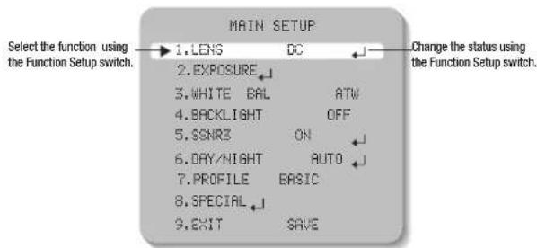
Menu Setup
Use the Function Setup switch within the camera.

text_image
Function Setup switch- Press the Function Setup switch.
- Main SETUP menu is displayed on the monitor screen.
text_image
MAIN SETUP 1.LENS DC 2.EXPOSURE 3.WHITE BAL ATW 4.BACKLIGHT OFF 5.SSNR3 ON 6.DAY/NIGHT AUTO 7.PROFILE BASIC 8.SPECIAL 9.EXIT SAVE Select the function using the Function Setup switch. Change the status using the Function Setup switch.- Select a desired function using the Function Setup switch.
- Place the cursor over a desired item.
-
Set up a selected item by using the Function Setup switch.
-
To finish the setting, select 'EXIT' and press the Function Setup switch.
Operating Your Camera
Notes
- An item with the icon also has sub menus. To select a sub menu, select an item with the icon and press the Function Setup switch.
- An item with the --- icon is unavailable due to function settings.
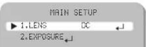
LENS
Using this function, you can control the screen brightness.
-
When the SETUP menu screen is displayed, select 'LENS' by using the Function Setup switch so that the arrow indicates 'LENS'.
-
The Lens mode has sub menu site as listed below.
- BRIGHTNESS : Adjusts the video brightness.
- FOCUS ADJ : To adjust the lens focus correctly, you must activate the Focus Settings mode. To activate the Focus Settings mode, adjust the lens focus, and then deactivate the settings mode. You can adjust the shutter value of ESC shutter mode.
Notes
- Set the shutter mode to --- if color rolling occurs.
EXPOSURE

- When the SETUP menu screen is displayed, select 'EXPOSURE' by using the Function Setup switch so that the arrow indicates 'EXPOSURE'.
- Select a desired mode using the Function Setup switch.
EXPOSURE SETUP
▶1.BRIGHTNESS 25
2.SHUTTER
3.AGC HIGH
4.SENS-UP OFF
5.RETURN
BRIGHTNESS: Adjusts the video brightness.
SHUTTER: You can select the shutter.
- --- : Shutter speed is fixed at 1/60 sec (1/50 sec).
- ESC : Select this to control the shutter speed automatically. If ESC is selected, the shutter speed is automatically controlled depending on the ambient illumination of the subject.
- MANUAL : You can control shutter speed manually.
(NTSC MODEL - 1/60sec\~1/120,000sec, PAL MODEL - 1/50sec\~1/120,000sec)
- A.FLK : Select this when you experience picture flicker, this happen when there is a clash with the installed lighting frequency.
Notes
- Set the shutter mode to --- if color rolling occurs.
- When the SHUTTER is set to ESC after selecting the Internal Synchronization Type, the picture may become unstable if the camera faces a bright fluorescent light. Therefore, take care when choosing the installation position.
- When the SHUTTER is set to MANUAL or A.FLK mode, SENS-UP will be disabled.
AGC(AUTO GAIN CONTROL): The higher the gain level, the brighter the screen - but the greater the noise.
- OFF : Deactivates the AGC function.
- LOW : Allows automatic gain control from 5.3dB to 32dB.
· HIGH : Allows automatic gain control from 5.3dB to 37dB.
SENS-UP: When it is night or dark, the camera automatically detects the light level and maintains a clear picture if this mode is activated. - OFF : Deactivates the SENS-UP function.
AUTO : Activates the SENS-UP function.
Operating Your Camera
Notes
- If you set the Function Setup switch to 'AUTO' mode, You can adjust the brightness by increasing or decreasing the shutter speed. (x2 \~ x512)
- Note that the higher the zoom level, the brighter the screen, but the more likely it is that an after-image will appear.
- Although Noise, Spots and Whittish symptoms may occur in SENS-UP operation when the zoom level is increased, this is normal.
RETURN : Select this to save the changes in the EXPOSURE menu and return to the SETUP menu.
WHITE BAL (White Balance)
Use the White Balance function to adjust the screen color.
- When the SETUP menu screen is displayed, select 'WHITE BAL' by using the Function Setup switch so that the arrow indicates 'WHITE BAL'.
- Select a desired mode using the Function Setup switch.
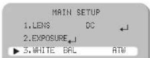
※ Select one of the following 5 modes, as appropriate for your purpose.
ATW : Select this when the color temperature is between 1,700°K and 11,000°K.
OUTDOOR : Select this when the color temperature is between 1,700°K and 11,000°K. (sodium light inclusion)
INDOOR : Select this when the color temperature is between 4,500K and 8,500K.
MANUAL : Select this to fine-tune White Balance manually. Set White Balance first by using the ATW or AWC mode. After that switch to MANUAL mode, fine-tune the White Balance and the Function Setup switch.
AWC → SET : To find the optimal luminance level for the current environment, point the camera towards a sheet of white paper and press the Function Setup switch. If the environment changes, readjust it.
Notes
- White Balance may not work properly under the following conditions. In this case select the OUTDOOR mode.
When the color temperature of the environment surrounding the subject is out of the control range (e.g. clear sky or sunset).
2 When the ambient illumination of the subject is dim.
3 If the camera is directed towards a fluorescent light or is installed in a place where illumination changes dramatically, the White Balance operation may become unstable.
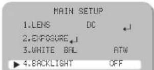
BACKLIGHT
The SUD-3080 is designed so that it delivers a distinctive subject and background at the same time, even when the subject is in backlight, by adopting a function of the proprietary SV-V DSP chip.
- When the SETUP menu screen is displayed, select 'BACKLIGHT' by using the Function Setup switch so that the arrow indicates 'BACKLIGHT'.
text_image
MAIN SETUP 1.LENS DC 2.EXPOSURE 3.WHITE BAL ATW ► 4.BACKLIGHT OFF- Select a desired mode using the Function Setup switch depending on the camera purpose.
OFF: Not being used
BLC : Enables a user to select a desired area on a picture and view that area more clearly.
- LEVEL : Adjusts the brightness level of a monitoring area.
- TOP/BOTTOM/LEFT/RIGHT : Adjust the area to be enhanced.
Operating Your Camera
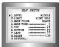
HLC (High Light Compensation):
If the scene contains extremely bright light areas such as; from car headlight, the light can mask out much of the on-screen detail.
- LEVEL : Adjusts the brightness level of a monitoring area.
- LIMIT : Enable to change the operating condition.
- MASK COLOR/TONE: Change the color / brightness of the masking area.
(Black, Red, Blue, Cyan, Magenta)
- TOP/BOTTOM/LEFT/RIGHT : Adjust the area to be enhanced.
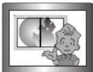
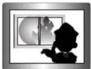
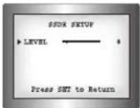
SSDR (Samsung Super Dynamic Range) : SSDR illuminates darker areas of an image while retaining the same light level for brighter areas to even out the overall brightness of images with high contrast between bright and dark areas. Use the Function Setup switch to change the SSDR level in the sub menu according to the contrast between bright and dark areas.
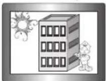
SSDR ON
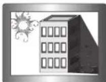
SSDR OFF
- WDR: When there are both bright and dark areas at the same time, this mode makes both areas distinctive.
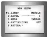
< WDR >
Select "WDR" to adjust the WDR LIMIT and LEVEL.
- LIMIT: Adjust the WDR Sensitivity by selecting LOW, MIDDLE or HIGH.
- LEVEL: Adjust the WDR Brightness by controlling the bar from 1 to 100.
- MODE : Indoor and outdoor backlight conditions are appropriately selected.
-
ANTI ROLLING : Rolling caused around a fluorescent lamp is improved.
-
Select a desired mode using the Function Setup switch.
BLC: Adjust the area to be enhanced then adjust the level.
HLC : Enable the user to change the level, limit, mask color/tone and area.

SSDR : Enable the user to change the level.
WDR : Enable the user to change the limit and level.
Notes
- Because there can be a difference in the effectiveness of HLC according to the amount of light area in the screen, optimize the installation angle for the best HLC performance.
- When dark, the HLC is only activated when a bright light exceeding a specific size. (In NIGHT ONLY mode).
- The HLC is not activated in day light or when bright light is not present at night. (In NIGHT ONLY mode).
- When using the WDR function, the shutter is only available with the fixed(---) mode.
- Since the performance of the WDR function may be affected by the area of the bright part of the screen, optimize the installation angle for the best WDR performance.
- If you increase LIMIT, the screen display may be distorted.
- If you use the VPS (Virtual Progressive Scan) function, the CCD reads differently so you can not use WDR simultaneously. If you set VPS to ON, WDR will be automatically set to FIXED Mode.
Operating Your Camera
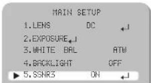
SSNR3
This function reduces the background noise in a low luminance environment.
- When the SETUP menu screen is displayed, select 'SSNR3' by using the Function Setup switch so that the arrow indicates 'SSNR3'.
text_image
MAIN SETUP 1.LENS DC ←J 2.EXPOSURE_↓ 3.WHITE BAL ATM 4.BACKLIGHT OFF 5.SSNR3 ON ←J- Select a desired mode using the Function Setup switch.
ON : Activates SSNR3 so that noise is reduced.
OFF: Deactivates SSNR3. Noise is not reduced.
- Set the SSNR3 mode to 'ON' and press the Function Setup switch. Then you can adjust the noise reduction level.

Notes
- You cannot set the SSNR3 to 'ON' or 'OFF' when the AGC mode of the 'EXPOSURE' menu is 'OFF'.
- When adjusting the noise reduction level in the SSNR3 mode, remember that the higher the level set, the more the noise level will be reduced, as will the brightness of the image.
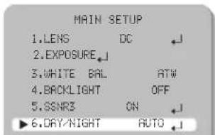
DAY/NIGHT
You can display pictures in color or in black and white.
- When the SETUP menu screen is displayed, select 'DAY/NIGHT' by using the Function Setup switch so that the arrow indicates 'DAY/NIGHT'.
text_image
MAIN SETUP 1.LENS DC 2.EXPOSURE 3.WHITE BAL ATW 4.BACKLIGHT OFF 5.SSNR3 ON 6.DAY/NIGHT AUTO- Select a desired mode using the Function Setup switch according to the picture display you want.
AUTO : The mode is switched to 'Color' in a normal environment, but switches to 'B/W' mode when ambient illumination is low. To set up the switching time for AUTO mode, press the Function Setup switch. You can turn on or off the burst signal on B/W mode.
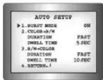
- BURST MODE : You can turn on or off the burst signal on BW mode.
- DURATION: You can select the day/night switching point.
- DWELL TIME: You can select day/night switching delay time from. →3s, 5s, 7s, 10s, 15s, 20s, 30s, 40, 60s
| Color → B/W B/W → Color | ||
| Early | 2.5 lux 5 lux | |
| Late | 1 lux 7 lux | |
* The day/night switching point of the camera can be adjusted.
○ EXTERN : This mode allows you to apply a desired filter to external signals.
COLOR : The picture is always displayed in color.
B/W : The picture is always displayed in black and white. You can turn on or off the burst signal on B/W mode.
Operating Your Camera
Notes
- When AGC in the EXPOSURE menu is 'OFF', '---' mode operates as selecting 'COLOR' mode and 'AUTO' mode cannot be selected.
- Be sure to connect the Day & Night input terminal to GND when using an external input.
PROFILE
- When the SETUP menu screen is displayed, select 'PROFILE' by using the Function Setup switch so that the arrow indicates 'PROFILE'.

text_image
MAIN SETUP 1.LENS DC 2.EXPOSURE 3.WHITE BAL ATW 4.BACKLIGHT OFF 5.SSNR3 OH 6.DAY/HIGHT AUTO 7.PROFILE BASIC 8.SPECIAL 9.EXIT SAVE- Select a desired mode using the Function Setup switch according to the picture display you want.
BASIC : The most common environment is set to meet.
DAY/NIGHT: It will be set automatically so it optimizes to the day or night conditions, respectively.
- BACKLIGHT: It will be set automatically so you can distinguish the object from the background in a severe backlighting scene.
- ITS: It will be set automatically so you can easily check the traffic conditions.
INDOOR: It will be set automatically to help you take a picture in a regular indoor lighting condition.
- USER : Automatically configures the camera to your custom settings.
① Select Custom for Simple Setup mode.
② Configure the menu options to your custom settings.
3 The settings are automatically saved as Custom mode.
4 Profile user mode don't initialize when menu resets.
- In the PROFILE menu, you can configure the following camera settings at once.
| BASIC DAY/NIGHT | BACKLIGHT | ITS INDOOR USER | ||||
| SHUTTER --- | --- | --- | MANUAL(1/250) | A.FLK | - | |
| GAIN | HIGH | HIGH | HIGH | HIGH | HIGH | - |
| WHITE BAL | ATW | ATW | ATW | OUTDOOR | INDOOR | - |
| BACKLIGHT | OFF | OFF | USER BLC | OFF | OFF | - |
| SSNR3 | ON | ON | ON | ON | ON | - |
| DAY/NIGHT | AUTO | AUTO | AUTO | AUTO | AUTO | - |
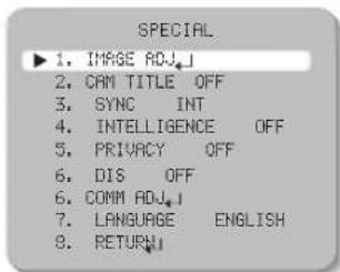
SPECIAL
- When the SETUP menu screen is displayed, select 'SPECIAL' by using the Function Setup switch so that the arrow indicates 'SPECIAL'.

text_image
MAIN SETUP 1.LENS DC 2.EXPOSURE 3.WHITE BAL ATW 4.BACKLIGHT OFF 5.SSNR3 ON 6.DAY/NIGHT AUTO 7.PROFILE BASIC 8.SPECIAL 9.EXIT SAVEOperating Your Camera

- Select a desired mode using the Function Setup switch.
text_image
SPECIAL ▶ 1. IMAGE ADJ.J 2. CAM TITLE OFF 3. SYNC INT 4. INTELLIGENCE OFF 5. PRIVACY OFF 6. DIS OFF 6. COMM ADJ.J 7. LANGUAGE ENGLISH 8. RETURNIMAGE ADJ :
1) When the SPECIAL menu screen is displayed, select 'IMAGE ADJ' by using the Function Setup switch so that the arrow indicates 'IMAGE ADJ'.
2) Select a desired mode using the Function Setup switch.
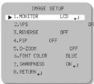
text_image
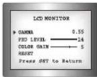
IMAGE SETUP ▶1. MONITOR LCD 2.VPS OFF 3. REVERSE OFF 4.PIP OFF 5. D-ZOOM OFF 6. FONT COLOR BLUE 7. SHARPNESS ON 8. RETURN- MONITOR: Please change the settings value of video appropriate to your monitor. - LCD: Please select this menu item when using an LCD monitor. You can change the gamma, PED level and color gain in the sub menus.
- CRT : Please select this menu item when using a CRT monitor. You can change the PED level, color gain in the sub menus.
- USER : Please use this menu item when using a monitor other than standard ones. You can change the gamma, PED level and color gain in the sub menus.
- VPS(Virtual Progressive Scan): This is an advanced technology that reproduces a sharp progressive image. This is appropriate to high quality recording and file transfer via the Internet.
- OFF : Selects 2:1 Interlaced Scan as the Imaging Method. - ON : Selects Progressive Scan as the Imaging Method.
● REVERSE : You can reverse the picture.
- OFF: You don't reverse the picture.
• H-REV : You can flip the picture horizontally on the screen.
• V-REV: You can flip the picture vertically on the screen.
- HV-REV: You can flip the picture horizontally and vertically on the screen.
- PIP(Picture in Picture) : Displays a full-size image along with the thumbnail to provide more detailed information. The position of the thumbnail is adjustable.
● D-ZOOM: You can use a digital zoom of x1 \~ x16.
● FONT COLOR : You can change the OSD font color. (White, Yellow, Green, Red, Blue)
● SHARPNESS : As you increase this value, the picture outline becomes stronger and clearer. Adjust this value appropriately depending on the sharpness of the picture.
● RETURN : Select this to save the settings for the IMAGE ADJ menu and to return to the SPECIAL menu.


Operating Your Camera
Notes
- When the V-REV or H-REV mode is enabled, the text on the screen does not flip.
- If you increase the SHARPNESS level too high, the picture may become distorted or noise may appear.
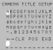
CAM TITLE: If you enter a title, the title will appear on the monitor.
1) If the SPECIAL menu screen is displayed, use the Function Setup switch so that the arrow indicates 'CAM TITLE'.
2) Set it to 'ON' by using the Function Setup switch. Press the Function Setup switch.
4) Use the Function Setup switch to move to a desired letter and select the letter by pressing the Function Setup switch. Repeat this to enter multiple letters. You can enter up to 15 letters.
5) Enter a title, move the cursor to 'POS' and press the Function Setup switch. The entered title appears on the screen. Select the position to display the title on the screen by using the Function Setup switch and press the Function Setup switch. When the position is determined, select 'END' and press the Function Setup switch to return to the SPECIAL menu.
Notes
- When the CAM TITLE menu is 'OFF', no title will be displayed on the monitor screen even if you enter one.
- English and Numbers are available in this mode.
- If you move the cursor to CLR and press the Function Setup switch, all the letters are deleted. To edit a letter, change the cursor to the bottom left arrow and press the Function Setup switch. Move the cursor over the letter to be edited, move the cursor to the letter to be inserted and then press the Function Setup switch.
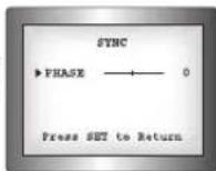
SYNC: In areas where the supply is at 60Hz(NTSC), 50Hz(PAL) frequency, you can synchronize the output phase of multiple cameras using the power synchronization function (Line-Lock) without using a synchronization signal generator.
- INT : Internal Synchronization Type
• L/L : Power Synchronization Type, Line-lock
1 Press the Function Setup switch.
② You can select a desired phase from 0 to 359 when select 'phase'.
Notes
- When using AC power at 60Hz(NTSC), 50Hz(PAL) frequency, you can use the L/L type synchronization.
- When the power is DC 12V, the SYNC menu is fixed to the 'INT' mode.
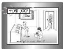
INTELLIGENCE : Commands the camera to motion-detect and trace an object.
INTELLIGENCE
▶i. MOTION OFF
2. DETECT BOX ON
3. ALARM OUT OFF
4. DETECT AREA
5. MASK AREA
6. SENSITIVITY
7. DET. SIZE 3
8. RETURN
Operating Your Camera
● MOTION : Select motion types to detect.
• OFF: Not being used.
- DETECTION: Since the camera detects motion without any additional external sensor, you can monitor activity more efficient.
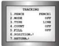
- TRACKING : Commands the camera to detect and trace a moving object.
▶FENCE : You can select up to 4 FENCE.
▶MODE : Determines whether to use the fence selected in the FENCE.
▶TYPE : Two types, line and area, of fences are available.
COUNT : Displays the number of times that an object enters or leaves a fenced area.
▶FILL : Fill or remove color from the FENCE.
▶POSITION: Defines the position and detection direction of a line or fenced area.
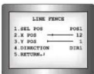
1) LINE FENCE
SEL POS : Selects a position from POS1,POS2.
- X POS / Y POS : Adjust the size and position of the selected line fence.
- DIRECTION
- DIR1: Detects objects moving left to right on the fence line.
- DIR2: Detects objects moving right to left on the fence line.
- DIR1/2: Detects all objects moving crosswise on the fence line.
RETURN : Select this to save the POSITION menu settings and return to the TRACKING menu.
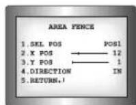
2) AREA FENCE
- SEL POS : Selects a position from POS1 \~ POS4.
- X POS / Y POS : Adjust the size and position of the selected area fence.
DIRECTION
• IN : Detects objects entering the fenced area.
- OUT: Detects objects exiting the fenced area
• IN/OUT : Detects all objects entering and exiting the fenced area.
- RETURN : Select this to save the POSITION menu settings and return to the TRACKING menu.
▶ RETURN : Select this to save the TRACKING menu settings and return to the INTELLIGENCE menu.
- FIXED/MOVED: Detects an object that emerges or disappears from the screen, or stays onscreen without movement.
Notes
•A detection (FIXED/MOVED) error may occur if :
· multiple motions occur continuously in random directions
· a fixed object moves in one position continuously
· a second object screens the first moving object
- DETECT BOX : Outlines an object on the screen in a box when its movement matches a custom Motion Type.
- ALARM OUT: Releases a signal from the MD Output Terminal of the External Cable when an object's movement matches a custom Motion Type.
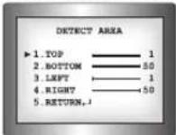
● DETECT AREA : Defines the Motion Detection area.
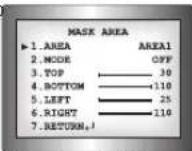
● MASK AREA: Specify a detection exception area to mask.
Select a mask area number and specify the size and position.
▶ AREA : You can select up to 4 areas.
▶MODE: Determines whether to use the area selected in the AREA.
TOP / BOTTOM / LEFT / RIGHT : Adjust the size and position of the selected area.
Operating Your Camera
▶ RETURN : Select this to save the MASK AREA menu settings and return to the INTELLIGENCE menu.
● SENSITIVITY: Set the sensitivity of the motion detection. When adjusting the sensitivity, note that the lower the level means the higher sensitivity.
- DETECT SIZE Selects an object size to detect on the screen. When adjusting the detection size, note that the higher the level means the bigger detection size.
- RETURN: Select this to save the INTELLIGENCE menu settings and return to the SPECIAL menu.
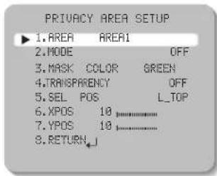
- PRIVACY: Mask an area you want to hide on the screen.
text_image
PRIVACY AREA SETUP ▶ 1.AREA AREA1 2.MODE OFF 3.MASK COLOR GREEN 4.TRANSparency OFF 5.SEL POS L_TOP 6.XPOS 10 7.YPOS 10 8.RETURN_↓1) When the SPECIAL menu screen is displayed, press the Function Setup switch so that the arrow indicates 'PRIVACY'.
2) Set up the mode using the Function Setup switch.
● AREA: You can select up to 12 PRIVACY areas.
● MODE : Determines whether to use the area selected in the AREA.
● MASK COLOR : Determine area color. You can select Green, Red, Blue, Black, White, Gray.
● TRANSPARENCY : Adds or removes transparency from the masking area.
- SEL POS/ XPOS/ YPOS : Adjust the size and position of the selected area.
- RETURN: Select this to save the PRIVACY menu settings and return to the SPECIAL menu.
DIS (Digital Image Stabilizer): This function mitigates any picture movement due to external factors such as wind.
Notes
- As the DIS function uses the digital zoom, the camera's resolution will decrease.
• DIS doesn't operate when background illumination is too low. - DIS doesn't operate when object pattern is monotonic as like sky or white wall.
COMM ADJ (Communication Adjustment) :
This function sets up the camera communication status when controlling the camera through an external control device.
1) When the SPECIAL menu screen is displayed, press the Function Setup switch so that the arrow indicates 'COMM ADJ'.
2) Set up the mode using the Function Setup switch.
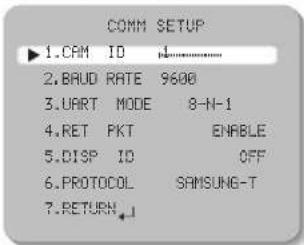
text_image
COMM SETUP ▶1.CAM ID ↓ 2.BAUD RATE 9600 3.UART MODE 8-N-1 4.RET PKT ENABLE 5.DISP ID OFF 6.PROTOCOL SAMSUNG-T 7.RETURN ↓● CAM ID: Determines the camera's identification number (between 0 and 255).
● BAUD RATE: You can select 2400/4800/9600/19200/38400/57600 bps
● UART MODE : You can select NONE, EVEN or ODD for the parity bits.
- RET PKT: Determines whether to send a command back to the controller device when a communication control command is sent to the camera.
● DISP ID : Display camera title on top left corner of the screen
● PROTOCOL : Select the communication PROTOCOL (SAMSUNG-T, SAMSUNG-E, PELCO-D, PELCO-P, BOSCH, HONEYWELL, VICON and PANASONIC)
- RETURN: Select this to save the PRIVACY menu settings and return to the SPECIAL menu.
* Initial value of communication adjustment
| Item | Camera ID | BAUD RATE UART MODE | PET PKT | |
| Initial value | 1 | 9600 | 8-NONE-1 | ENABLE |
Operating Your Camera

LANGUAGE : You can select the menu language according to your requirements.
RETURN : Select this to save the SPECIAL menu settings and return to the MAIN SETUP menu.
EXIT
Select a desired EXIT mode using the Function Setup switch depending on the camera purpose.
SAVE : Save the current settings and exit the MAIN SETUP menu.
NOT SAVE : Do not save the current settings and exit the MAIN SETUP menu.
RESET : Resets the camera settings to the factory defaults. Communication, Language and Monitor settings are not initialized.

Troubleshooting
If you have trouble operating your camera, refer to the following table.
If the guidelines do not enable you to solve the problem, contact an authorized technician.
● Nothing appears on the screen.
Check that the power cord and line connection between the camera and monitor are properly connected.
▶ Check that you have properly connected UTP cable or BNC cable to the camera.
▶ Check the pin arrangement for the UTP cable. (TIA/EIA-568B)
● The image on the screen is dim.
Is lens stained with dirt? Clean your lens with soft, clean cloth.
▶ Set the monitor or DVR to the proper condition.
▶If the camera is exposed to very strong light, change the camera position.
● The image on the screen is dark.
Adjust the contrast feature of the monitor or DVR.
If you have an intermediate device, set the 75Ω / Hi-z properly.
● The camera is not working properly, and the surface of the camera is hot.
▶ Check that you have properly connected the camera to an appropriate power source.
● The DAY/NIGHT menu does not work.
▶ Check that AGC of EXPOSURE SETUP menu is 'OFF'.
● The SENS-UP function does not work.
▶ Check that AGC of EXPOSURE SETUP menu is 'OFF'.
▶ Check that SHUTTER of EXPOSURE SETUP menu is 'A.FLK' or 'MANUAL'.
● The INTELLIGENCE function does not work.
▶ Check that INTELLIGENCE of menu is 'OFF'.
● Color is not correct.
▶ Check the setting of WHITE BAL SETUP menu
● The screen flickers continually.
▶ Ensure the camera is not pointing towards the sun.
● When coaxial communication is not available:
Make sure that the camera and monitor are installed within the recommended distance.
Use the video amplifier equivalent to coaxiron if the recommended installation distance is exceeded.
● Picture is distorted.
▶ Check the length of the UTP cable (900m(3000ft) or less).
● The camera does not work, and the video feed from the camera is not being received.
Check the Power Supply to see whether the connection status and pin arrangement for the camera's UTP cable and the Camera Input UTP cable are normal.
● The camera is out of focus.
▶ Check that you have properly adjusted the zoom / focus adjustment lever of lens.
Specifications
| SUD-3080 NTSC SUD-3080 PAL | ||
| ELECTRICAL | ||
| Input Voltage AC 26V±10% / AC 24V±10% / DC 12V±10% | ||
| Power Consumption Max 4.0W | ||
| VIDEO | ||
| Imaging Device | 1/3 inch Color Double Density CO | |
| Total Pixels / Effective Pixels | 811(H) x 508(V) / 768(H) x 494(V) 795(H) x 596(V) / 752(H) x 582(V) | |
| Scanning System 2:1 Interface / Progressive | ||
| Synchronization Internal / Line-Lock | ||
| Frequency | H : 15.734KHzV : 59.94Hz | H : 15.625KHzV : 50.00Hz |
| Horizontal Resolution COI | OR : 600TVL / BW : 700 TVL | |
| Min. Illumination | COLOR : 0.3 Lux(50IRE,F1.2),0.0006 Lux(SENS-UP X512)BW : 0.01 Lux(50IRE,F1.2),0.00002 Lux(SENS-UP X512) | |
| Video Output CVBS : 1.0Vp-p, 75Ω composite | ||
| UTP Built-in UTP TX (Maximum transmission length 900m(3000ft) :Balanced differential signal 100Ω | ||
| LENS | ||
| Zoom Ratio 3.9x (Manual) | ||
| Focus Length 2.8 - 11mm (F1.2) | ||
| Angular Field of View | H : 102.0°(Wide) - 28.0°(Tele) / V : 73.0°(Wide) - 21.0°(Tele) | |
| PAN / TILT / ROTATE | ||
| Fan/Tilt/Rotate Range 0° | ~ 340° / 0° ~ 73° / 0° ~ 340° | |
| OPERATIONAL | ||
| Electronic Shutter Speed | 1/60 - 1/120k sec | 1/50 - 1/120k sec |
| Shutter Mode ESC, MANUAL, A.FLK, FIXED | ||
| On Screen Display (NTSC : 7 / PAL : 15) | NTSC : English, Korean, Japanese, Spanish, French, Portuguese, TaiwanesePAL : English, Chinese, German, Italian, French, Spanish, Russian, Czech, Polish, Romanian, Serbian, Swedish, Danish, Turkish, Portuguese | |
| SUD-3080 NTSC SUD-3080 PAL | |
| Gain Control | OFF / LOW / HIGH |
| SENS-UP (frame integration) | OFF / Auto (Selectable x2 - x512) |
| White Balance | ATW / OUTDOOR / INDOOR / MANUAL / AWC (1,700°K ~ 11,000°K) |
| Backlight Compensation | OFF / USER BLC / HLC / SSDR / WDR |
| 3D Noise Filter (SSNRII) | OFF / ON (Level adjustable) |
| Day & Night | AUTO / EXTERN / COLOR / BW |
| Profil le | BASIC / DAY/NIGHT / BACKLIGHT / ITS / INDOOR / USER |
| Digital Zoom | OFF / ON (x1 ~ x16) |
| Sharpness | OFF / ON (Level adjustable) |
| Camera Title | OFF / ON (Display 15 Characters) |
| SYNC | INT / Line-Lock |
| VPS(Virtual Progressive Scan) | OFF / ON |
| INTELLIGENCE | DETECTION / TRACKING / FIXED/MOVED / ALARM OUT |
| ETC PIP, REVERSE | |
| Privacy Masking | OFF / ON (12 Programmable zones, Polygonal type) |
| Digital Image Stabilization(DIS) | OFF / ON |
| Coaxial Communication | Polco Coaxitron |
| RS-485 Communication | SAMSUNG-T, SAMSUNG-E, PELCO-D, PELCO-P, BOSCH, HONEYWELL, VICON, PANASONIC |
| ENVIRONMENTAL | |
| Operating Temperature / Humidity | -10°C = +50°C / Less than 90% RH |
| MECHANICAL | |
| Dimension | ∅141.2 x 105.5mm |
| Weight | 520g |
* The specification for this product may change without prior notice for product improvement. * This specification is based on a transmission distance of 500 meters; in cases of long-distance transmissions, some degradation in picture quality may occur depending on the operating environment.
Dimension

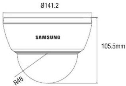
text_image
Ø141.2 SAMSUNG 105.5mm R48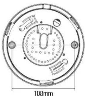
natural_image
Technical drawing of a circular mechanical component with internal features and a 108mm dimension label (no text or symbols beyond the dimension)DECLARATION OF CONFORMITY
Application of Council Directive(s) 2004 / 108 / EC
Manufacturer's Name SAMSUNG TECHWIN CO., LTD
Manufacturer's Address SAMSUNG TECHWIN CO., LTD
42, SUNGJU-DONG CHANGWON-CITY,
KYUNGNAM, KOREA, 641-716
European Representative Name
European Representative Address
Equipment Type/Environment CCTV Camera
Model Name SUD-3080P
Beginning Serial NO. C58T6V3Z300001X
Year of Manufacture 2010.03.01
Conformance to EN 55022 : 2006
EN 50130-4 : 2003
We, the undersigned, hereby declare that the equipment specified above conforms to the above Directive(s).
Manufacturer SAMSUNG TECHWIN CO., LTD Legal Representative in Europe
Signature Signature
Full Name BONJENG GU Full Name
Position QUALITY CONTROL MANAGER Position
Place CHANGWON, KOREA Place
Date 2010.03.01 Date
text_image
MEMO MEMO COLOR DOME CAMERA SU73080 COLOR DOME CAMERA SU73080SAMSUNG TECHWIN

SALES NETWORK
SAMSUNG TECHWIN CO., LTD.
701, Sampyong-dong, Bundang-gu, Seongnam-si Gyeonggi-do, Korea, 463-400
TEL : +82-70-7147-8740\~60 FAX : +82-31-8018-3745
Tol Free: +1-877-213-1222 FAX: +1-310-632-2195
www.samsungcctvusa.com
SAMSUNG TECHWIN EUROPE LTD.
Samsung House, 1000 Hillswood Drive, Hillswood Business Park
Chertsey, Surrey, UNITED KINGDOM KT16 OPS
TEL: +44-1932-45-5300 FAX: +44-1932-45-5325