NWA3550-N - Access Point ZYXEL - Free user manual and instructions
Find the device manual for free NWA3550-N ZYXEL in PDF.

User questions about NWA3550-N ZYXEL
0 question about this device. Answer the ones you know or ask your own.
Ask a new question about this device
Download the instructions for your Access Point in PDF format for free! Find your manual NWA3550-N - ZYXEL and take your electronic device back in hand. On this page are published all the documents necessary for the use of your device. NWA3550-N by ZYXEL.
USER MANUAL NWA3550-N ZYXEL
Wireless N Business WLAN 3000 Series Access Point
User's Guide
NWA3560-N: 802.11 a/b/g/n Dual-Radio Business Access Point (Indoor)
NWA3160-N: 802.11 a/b/g/n Business Access Point (Indoor)
NWA3550-N: 802.11 a/b/g/n Dual-Radio Outdoor Business Access Point (Outdoor)
Default Login Details
IP Address https://192.168.1.2
User Name admin
Password 1234
Version 2.23
Edition 1, 7/2011
www.zyxel.com
ZyXEL
About This User's Guide
Intended Audience
This manual is intended for people who want to configure a device using the web configurator. You should have at least a basic knowledge of TCP/IP networking concepts and topology.
Related Documentation
- Quick Start Guide
The Quick Start Guide is designed to help you get up and running right away. It contains information on setting up your network and configuring for Internet access.
• Support Disc
Refer to the included CD for support documents.
• Z y X E L W e b S i t e
Please refer to www.zyxel.com for additional support documentation and product certifications.
User Guide Feedback
Help us help you. Send all User Guide-related comments, questions or suggestions for improvement to the following address, or use e-mail instead. Thank you!
The Technical Writing Team,
ZyXEL Communications Corp.
E-mail: techwriters@zyxel.com.tw
Document Conventions
Warnings and Notes
These are how warnings and notes are shown in this User's Guide.
Warnings tell you about things that could harm you or your device.
Note: Notes tell you other important information (for example, other things you may need to configure or helpful tips) or recommendations.
Syntax Conventions
- The product in this book may be referred to as the “device”, the “device”, the “AP”, or the “system” in this User’s Guide.
- Product labels, screen names, field labels and field choices are all in bold font.
- A key stroke is denoted by square brackets and uppercase text, for example, [ENTER] means the "enter" or "return" key on your keyboard.
- “Enter” means for you to type one or more characters and then press the [ENTER] key. “Select” or “choose” means for you to use one of the predefined choices.
- A right angle bracket ( > ) within a screen name denotes a mouse click. For example, Maintenance > Status > Show Statistics means you first click Maintenance in the navigation panel, then the Status sub menu and finally the Show Statistics button to get to that screen.
- Units of measurement may denote the "metric" value or the "scientific" value. For example, "k" for kilo may denote "1000" or "1024", "M" for mega may denote "1000000" or "1048576" and so on.
- “e.g.,” is a shorthand for “for instance”, and “i.e.,” means “that is” or “in other words”.
- Screens reproduced here for demonstration purposes may not exactly match the screens on your device.
Icons Used in Figures
Figures in this User's Guide may use the following generic icons. The device icon is not an exact representation of your device.
device Computer Notebook  | computer  |  |
Server Printer Firewall  |  |  |
Telephone Switch Router  |  |  |
Safety Warnings
- Do NOT use this product near water, for example, in a wet basement or near a swimming pool.
- Do NOT expose your device to dampness, dust or corrosive liquids.
- Do NOT store things on the device.
- Do NOT install, use, or service this device during a thunderstorm. There is a remote risk of electric shock from lightning.
- Connect ONLY suitable accessories to the device.
- ONLY qualified service personnel should service or disassemble this device.
- Make sure to connect the cables to the correct ports.
- Place connecting cables carefully so that no one will step on them or stumble over them.
• Always disconnect all cables from this device before servicing or disassembling. - Use ONLY an appropriate power adaptor or cord for your device.
- Connect the power adaptor or cord to the right supply voltage (for example, 110V AC in North America or 230V AC in Europe).
- Do NOT allow anything to rest on the power adaptor or cord and do NOT place the product where anyone can walk on the power adaptor or cord.
- Do NOT use the device if the power adaptor or cord is damaged as it might cause electrocution.
- If the power adaptor or cord is damaged, remove it from the power outlet.
- Do NOT attempt to repair the power adaptor or cord. Contact your local vendor to order a new one.
- Do not use the device outside, and make sure all the connections are indoors. There is a remote risk of electric shock from lightning.
- “Not to remove the plug and plug into a wall outlet by itself; always attach the plug to the power supply first before insert into the wall.”
- (In other words, do NOT remove the plug and connect it to a power outlet by itself; always attach the plug to the power adaptor first before connecting it to a power outlet.)
- Antenna Warning! This device meets ETSI and FCC certification requirements when using the included antenna(s). Only use the included antenna(s).
- If you wall mount your device, make sure that no electrical lines, gas or water pipes will be damaged.
- The PoE (Power over Ethernet) devices that supply or receive power and their connected Ethernet cables must all be completely indoors.
- The indoors versions of this product are for indoor use only (utilisation intérieure exclusivement).
This product is recyclable. Dispose of it properly.

Contents Overview
User's Guide 17
Introduction 19
The Web Configurator 27
Configuration Basics 43
Tutorials 49
Technical Reference 67
Dashboard 69
Monitor 75
Management Mode 93
LAN Setting 97
Wireless 101
Device HA 117
User 127
AP Profile 135
MON Profile 151
Certificates 157
System 175
Log and Report 205
File Manager 219
Diagnostics 229
Reboot 237
Shutdown 239
Troubleshooting 241
Product Specifications 251
Table of Contents
About This User's Guide....3
Document Conventions 4
Safety Warnings....6
Contents Overview 7
Table of Contents 9
Part I: User's Guide ...... 17
Chapter 1 Introduction....19
1.1 Overview 19
1.2 Applications for the device .... 20
1.2.1 AP + Bridge 20
1.2.2 MBSSID 21
1.3 Management Mode 22
1.4 Ways to Manage the device 22
1.5 Good Habits for Managing the device ....23
1.6 Hardware Connections ......24
1.7 LEDs 25
1.8 Starting and Stopping the device ....26
Chapter 2 The Web Configurator .... 27
2.1 Overview 27
2.2 Access 27
2.3 The Main Screen 29
2.3.1 Title Bar 29
2.3.2 Navigation Panel 30
2.3.3 Warning Messages 33
2.3.4 Site Map 33
2.3.5 Object Reference 33
2.3.6 Tables and Lists ....39
Chapter 3 Configuration Basics....43
3.1 Overview 43
3.2 Object-based Configuration ......43
3.3 Feature Configuration Overview 43
3.3.1 Feature 43
3.3.2 MGNT Mode 44
3.3.3 LAN Setting 44
3.3.4 Wireless 44
3.3.5 Device HA 44
3.4 Objects 45
3.4.1 User 45
3.4.2 AP Profile 45
3.4.3 MON Profile 46
3.5 System 46
3.5.1 WWW, SSH, TELNET, FTP, SNMP, and Auth. Server 46
3.5.2 Logs and Reports ......46
3.5.3 File Manager 46
3.5.4 Diagnostics 47
3.5.5 Shutdown 47
Chapter 4 Tutorials......49
4.1 Sample Network Setup ....49
4.1.1 Set the Management Modes 50
4.1.2 Set the LAN IP Address and Management VLAN (vlan99) 51
4.1.3 Set Up Wireless User Authentication 52
4.1.4 Create the AP Profiles (staff, guest) 54
4.2 Rogue AP Detection 57
4.2.1 Rogue AP Containment 61
4.3 Load Balancing 63
4.4 Dynamic Channel Selection 64
Part II: Technical Reference....67
Chapter 5 Dashboard....69
5.1 Overview 69
5.1.1 What You Can Do in this Chapter 69
5.2 Dashboard 69
5.2.1 CPU Usage 73
5.2.2 Memory Usage 74
Chapter 6
Monitor....75
6.1 Overview 75
6.1.1 What You Can Do in this Chapter ....75
6.2 What You Need to Know ....75
6.3 LAN Status 76
6.3.1 LAN Status Graph 78
6.4 AP List 79
6.4.1 Station Count of AP 80
6.5 Radio List 81
6.5.1 AP Mode Radio Information 82
6.6 Station List 84
6.7 Rogue AP 84
6.8 Legacy Device Info 85
6.8.1 Legacy Device Info Add or Edit 86
6.9 View Log 87
6.10 View AP Log 90
Chapter 7
Management Mode 93
7.1 Overview 93
7.2 About CAPWAP 93
7.2.1 CAPWAP Discovery and Management ....93
7.2.2 Managed AP Finds the Controller 94
7.2.3 CAPWAP and IP Subnets 94
7.2.4 Notes on CAPWAP 95
7.3 The Management Mode Screen 95
Chapter 8
LAN Setting 97
8.1 LAN Setting Overview 97
8.1.1 What You Can Do in this Chapter .....97
8.1.2 What You Need to Know 97
8.2 LAN Setting 98
8.2.1 Add or Edit a DNS Setting 100
Chapter 9
Wireless 101
9.1 Overview ...... 101
9.1.1 What You Can Do in this Chapter 101
9.1.2 What You Need to Know 101
9.2 Controller 102
9.3 AP Management 102
9.3.1 Edit AP List 104
9.4 MON Mode 105
9.4.1 Add/Edit Rogue/Friendly List 107
9.5 Load Balancing 108
9.5.1 Disassociating and Delaying Connections 109
9.6 DCS 111
9.7 Technical Reference 113
Chapter 10
Device HA 117
10.1 Overview 117
10.1.1 What You Can Do in this Chapter 117
10.1.2 What You Need to Know 117
10.1.3 Before You Begin 118
10.2 Device HA General 118
10.3 Active-Passive Mode 120
10.3.1 Edit Monitored Interface ...... 123
10.4 Technical Reference 123
Chapter 11
User 127
11.1 Overview 127
11.1.1 What You Can Do in this Chapter 127
11.1.2 What You Need To Know 127
11.2 User Summary 128
11.2.1 Add/Edit User 128
11.3 Setting 130
11.3.1 Edit User Authentication Timeout Settings 132
Chapter 12
AP Profile....135
12.1 Overview 135
12.1.1 What You Can Do in this Chapter 135
12.1.2 What You Need To Know 135
12.2 Radio 136
12.2.1 Add/Edit Radio Profile 138
12.3 SSID 142
12.3.1 SSID List 142
12.3.2 Security List 144
12.3.3 MAC Filter List 147
Chapter 13
MON Profile 151
13.1 Overview 151
13.1.1 What You Can Do in this Chapter 151
13.1.2 What You Need To Know 151
13.2 MON Profile 152
13.2.1 Add/Edit MON Profile 153
13.3 Technical Reference ...... 154
Chapter 14
Certificates 157
14.1 Overview ...... 157
14.1.1 What You Can Do in this Chapter 157
14.1.2 What You Need to Know .... 157
14.1.3 Verifying a Certificate 159
14.2 My Certificates 160
14.2.1 Add My Certificates 162
14.2.2 Edit My Certificates ...... 165
14.2.3 Import Certificates 167
14.3 Trusted Certificates ...... 168
14.3.1 Edit Trusted Certificates ...... 170
14.3.2 Import Trusted Certificates ...... 173
14.4 Technical Reference 173
Chapter 15
System 175
15.1 Overview 175
15.1.1 What You Can Do in this Chapter 175
15.2 Host Name 176
15.3 Date and Time 176
15.3.1 Pre-defined NTP Time Servers List 179
15.3.2 Time Server Synchronization 179
15.4 Console Speed 180
15.5 WWW Overview 181
15.5.1 Service Access Limitations .... 181
15.5.2 System Timeout .... 181
15.5.3 HTTPS 181
15.5.4 Configuring WWW Service Control 182
15.5.5 HTTPS Example 183
15.6 SSH 190
15.6.1 How SSH Works .... 191
15.6.2 SSH Implementation on the device 192
15.6.3 Requirements for Using SSH 192
15.6.4 Configuring SSH 192
15.6.5 Examples of Secure Telnet Using SSH 193
15.7 Telnet 195
15.8 FTP 195
15.9 SNMP 196
15.9.1 Supported MIBs 198
15.9.2 SNMP Traps 198
15.9.3 Configuring SNMP 198
15.9.4 Adding or Editing an SNMPv3 User Profile 200
15.10 Internal RADIUS Server 200
15.10.1 Configuring the Internal RADIUS Server 201
15.10.2 Adding or Editing a Trusted AP Profile 203
15.11 Technical Reference 204
Chapter 16
Log and Report 205
16.1 Overview ......205
16.1.1 What You Can Do In this Chapter 205
16.2 Email Daily Report ....205
16.3 Log Setting 207
16.3.1 Log Setting Summary ......208
16.3.2 Edit Log Settings 210
16.3.3 Edit Remote Server 213
16.3.4 Active Log Summary 214
Chapter 17
File Manager....219
17.1 Overview ......219
17.1.1 What You Can Do in this Chapter 219
17.1.2 What you Need to Know 219
17.2 Configuration File 220
17.3 Firmware Package 224
17.4 Shell Script 226
Chapter 18
Diagnostics 229
18.1 Overview 229
18.1.1 What You Can Do in this Chapter 229
18.2 Diagnostics 229
18.3 Packet Capture 230
18.3.1 Packet Capture Files 232
18.3.2 Example of Viewing a Packet Capture File 232
18.4 Wireless Frame Capture 233
18.4.1 Wireless Frame Capture Files 235
Chapter 19
Reboot 237
19.1 Overview ...... 237
19.1.1 What You Need To Know ....237
19.2 Reboot 237
Chapter 20
Shutdown....239
20.1 Overview ...... 239
20.1.1 What You Need To Know 239
20.2 Shutdown 239
Chapter 21
Troubleshooting....241
21.1 Overview 241
21.2 Power, Hardware Connections, and LEDs 241
21.3 device Access and Login 242
21.4 Internet Access 244
21.5 Wireless AP Troubleshooting ....245
21.6 Resetting the device 249
21.7 Getting More Troubleshooting Help 249
Chapter 22
Product Specifications....251
22.1 Wall-Mounting Instructions ......253
Appendix A Log Descriptions....255
Appendix B Importing Certificates 273
Appendix C Wireless LANs....287
Appendix D Open Software Announcements 299
Appendix E Legal Information....343
Index 351
PART I
User's Guide
1.1 Overview
Your device's business-class reliability, SMB features, and centralized wireless management make it ideally suited for advanced service delivery in mission-critical networks. The device provides secure mobility across the 2.4GHz and 5GHz spectrums and the IEEE 802.11n standard's high bandwidth to support high-performance applications. It uses Multiple BSSID and VLAN to provide up to eight simultaneous independent virtual APs. Additionally, innovations in roaming technology and QoS features eliminate voice call disruptions. It can serve as an AP, Bridge or even as an RF monitor to search for rouge APs to help eliminate network threats.
The device controls network access with Media Access Control (MAC) address filtering, rogue Access Point (AP) detection and containment, and an internal authentication server. It also provides a high level of network traffic security, supporting IEEE 802.1x, Wi-Fi Protected Access (WPA), WPA2 and Wired Equivalent Privacy (WEP) data encryption.
A device can manage up to 24 other devices on your network. Configuration profiles let you easily use different WLAN and security settings for various virtual and managed APs.
Your device is easy to install, configure and use. The embedded Web-based configurator enables simple, straightforward management and maintenance. See the Quick Start Guide for how to make hardware connections.
1.2 Applications for the device
The device can be configured to use the following operating modes
- A P + B r i d g e
- M B S S I D
Applications for each operating mode are shown below.
Note: A different channel should be configured for each WLAN interface to reduce the effects of radio interference.
1.2.1 AP + Bridge
In AP + Bridge mode, the device supports both AP and bridge connection at the same time.
In the figure below, A and B use X as an AP to access the wired network, while X and Y communicate in bridge mode.
When the device is in AP + Bridge mode, security between APs (WDS) is independent of the security between the wireless stations and the AP. If you do not enable WDS security, traffic between APs is not encrypted. When WDS security is enabled, both APs must use the same pre-shared key.
Unless specified, the term “security settings” refers to the traffic between the wireless stations and the device.
Figure 1 AP + Bridge Application

flowchart
graph TD
    subgraph Ethernet 1
        A["Computer"] -->|Ethernet 1| B["Device"]
        C["Printer"] -->|Ethernet 1| B
        D["Computer"] -->|Ethernet 1| B
    end
    subgraph Devices
        E["Computer"] -->|Ethernet 1| F["Device"]
        G["Printer"] -->|Ethernet 1| F
        H["Computer"] -->|Ethernet 1| F
        I["Computer"] -->|Ethernet 1| F
    end
    subgraph Wireless Circuits
        J["A"] --> K["B"]
        L["Y"] --> M["Y"]
    end
1.2.2 MBSSID
A Basic Service Set (BSS) is the set of devices forming a single wireless network (usually an access point and one or more wireless clients). The Service Set Identifier (SSID) is the name of a BSS. In Multiple BSS (MBSSID) mode, the device provides multiple virtual APs, each forming its own BSS and using its own individual SSID profile.
You can assign different wireless and security settings to each SSID profile. This allows you to compartmentalize groups of users, set varying access privileges, and prioritize network traffic to and from certain BSSs.
To the wireless clients in the network, each SSID appears to be a different access point. As in any wireless network, clients can associate only with the SSIDs for which they have the correct security settings.
See Section 4.1 on page 49 for an example of using MBSS.
1.3 Management Mode
One device uses Control And Provisioning of Wireless Access Points (CAPWAP, see RFC 5415) to allow one AP to configure and manage up to 24 others. This centralized management can greatly reduce the effort of setting up and maintaining multiple devices.
An device in this group (ZLD-based models) can manage other APs in this group ^1 .
• NWA3160-N
• NWA3550-N
• NWA3560-N
It can also use legacy device information hyper-links to connect to the Web Configurators of the following ZyNOS-based NWA-3000 series APs:
• NWA-3160
• NWA-3163
• NWA-3500
• NWA-3550
• NWA-3166
The following figure illustrates a CAPWAP wireless network. The user (U) configures the controller AP (C), which then automatically updates the configurations of the managed APs (M1 \~ M4).
Figure 2 CAPWAP Network Example

flowchart
graph TD
    U["User"] --> Switch["Switch"]
    Switch --> M1["M1"]
    Switch --> M2["M2"]
    Switch --> M3["M3"]
    Switch --> M4["M4"]
    M1 --> C["C"]
    M2 --> C
    M3 --> C
    M4 --> C
    C -->|Red Arrow| Switch
    Switch -->|Red Arrow| M1
    Switch -->|Red Arrow| M2
    Switch -->|Red Arrow| M3
    Switch -->|Red Arrow| M4
1.4 Ways to Manage the device
You can use the following ways to manage the device.
Web Configurator
The Web Configurator allows easy device setup and management using an Internet browser. This User's Guide provides information about the Web Configurator.
Command-Line Interface (CLI)
The CLI allows you to use text-based commands to configure the device. You can access it using remote management (for example, SSH or Telnet) or via the console port. See the Command Reference Guide for more information.
Console Port
You can use the console port to manage the device using CLI commands. See the Command Reference Guide for more information about the CLI. The default settings for the console port are as follows.
Table 1 Console Port Default Settings
| SETTING VALUE | |
| Speed 115200 bps | |
| Data Bits 8 | |
| Parity None | |
| Stop Bit 1 | |
| Flow Control Off |
File Transfer Protocol (FTP)
This protocol can be used for firmware upgrades and configuration backup and restore.
Simple Network Management Protocol (SNMP)
The device can be monitored by an SNMP manager. See the SNMP chapter in this User's Guide.
Controller
Set one device to be a controller and set other devices to be managed by it.
1.5 Good Habits for Managing the device
Do the following things regularly to make the device more secure and to manage it more effectively.
- Change the password often. Use a password that's not easy to guess and that consists of different types of characters, such as numbers and letters.
- Write down the password and put it in a safe place.
- Back up the configuration (and make sure you know how to restore it). Restoring an earlier working configuration may be useful if the device becomes unstable or even crashes. If you forget your password, you will have to reset the device to its factory default settings. If you backed up an earlier configuration file, you won't have to totally re-configure the device; you can simply restore your last configuration.
1.6 Hardware Connections
See your Quick Start Guide for information on making hardware connections.
1.7 LEDs
The following are the LED descriptions for your device.
Figure 3 LEDs

text_image
ZyXEL WLAN ETHN PWR\SYS WLAN ETHN PWR\SYSTable 2 LEDs
| LABEL COLOR | STATUS | DESCRIPTION | |||
| WLAN Green | On The wireless LAN is active. | ||||
| Blinking The wireless LAN is active, and transmitting or receiving data. | |||||
| Off The wireless LAN is not active. | |||||
| ETHERNET Green | On The device has a 10/100 Mbps Ethernet connection. | ||||
| Blinking The device has a 10/100 Mbps Ethernet connection and is sending or receiving data. | |||||
| Yellow On | The device has a 1000 Mbps Ethernet connection. | ||||
| Blinking The device has a 1000 Mbps Ethernet connection and is sending/receiving data. | |||||
| Off The device does not have an Ethernet connection. | |||||
| POWER/SYS Green On The device is receiving power and functioning properly. | |||||
1.8 Starting and Stopping the device
Here are some of the ways to start and stop the device.
Always use Maintenance > Shutdown or the shutdown command before you turn off the device or remove the power. Not doing so can cause the firmware to become corrupt.
Table 3 Starting and Stopping the device
| METHOD DESCRIPTION | |
| Turning on the power | A cold start occurs when you turn on the power to the device. The device powers up, checks the hardware, and starts the system processes. |
| Rebooting the device | A warm start (without powering down and powering up again) occurs when you use the Reboot button in the Reboot screen or when you use the reboot command. The device writes all cached data to the local storage, stops the system processes, and then does a warm start. |
| Using the RESET button | If you press the RESET button, the device sets the configuration to its default values and then reboots. |
| Clicking Maintenance > Shutdown > Shutdown or using the shutdown command | Clicking Maintenance > Shutdown > Shutdown or using the shutdown command writes all cached data to the local storage and stops the system processes. Wait for the device to shut down and then manually turn off or remove the power. It does not turn off the power. |
| Disconnecting the power | Power off occurs when you turn off the power to the device. The device simply turns off. It does not stop the system processes or write cached data to local storage. |
The device does not stop or start the system processes when you apply configuration files or run shell scripts although you may temporarily lose access to network resources.
The Web Configurator
2.1 Overview
The device Web Configurator allows easy management using an Internet browser.
In order to use the Web Configurator, you must:
- Use Internet Explorer 7.0 and later or Firefox 1.5 and later
- Allow pop-up windows
- Enable JavaScript (enabled by default)
- Enable Java permissions (enabled by default)
- Enable cookies
The recommended screen resolution is 1024 x 768 pixels and higher.
2.2 Access
1 Make sure your device hardware is properly connected. See the Quick Start Guide.
2 Browse to https://192.168.1.2. The Login screen appears.

text_image
Enter User Name/Password and click to login. User Name: Password: ( max. 63 alphanumeric, printable characters and no spaces ) Login Reset3 Enter the user name (default: "admin") and password (default: "1234").
4 Click Login. If you logged in using the default user name and password, the Update Admin Info screen appears. Otherwise, the dashboard appears.

text_image
Update Admin Info As a security precaution, it is highly recommended that you change the admin password. New Password: ••••• Retype to Confirm: •••••• ( max. 63 alphanumeric, printable characters and no spaces ) Apply IgnoreThis screen appears every time you log in using the default user name and default password. If you change the password for the default user account, this screen does not appear anymore.
2.3 The Main Screen
The Web Configurator's main screen is divided into these parts:
Figure 4 The Web Configurator's Main Screen

text_image
ZyXEL NWA3160-N Welcome admin | Help About Site Map Object Reference Consola CLI A B DASHBOARD C Device Information System Name: nwa3160-n Model Name: NWA3160-N Serial Number: S100D+2007113 MAC Address Range: 40:4A:03:42:70:12 ~ 40:4A:03:42:70:13 Firmware Version: 2.23(UJA.0)bat2 / 1.13 / 2010-10-25 03:48:20 System Status System Uptime: 00:42:49 Current Date/Time: 1970-01-01/00:44:42 GMT+00:00 Current Login User: admin (unlimited / 00:30:00) Boot Status: OK Management Mode: standalone System Resources CPU Usage 6 % Memory Usage 21 % Flesh Usage 36 % Interface Status Summary Name Status VID IP Addr/Netmask IP Assign Action lan 100M/Full 1 / 255 Static n/a WLAN Interface Status Summary Status MAC Address Radio Band OP Mode Chann Station 40:4A:03:42:7( 1 2.4G AP (MBSSID) 6 0 AP Information All Sensed Device: Un-Classified AP: 0 Rogue AP: 0 Friendly AP: 0 WDS Link Status Radio Link ID Peer MAC Address Securi Status• A - Title Bar
• B - Navigation Panel
- C - Main Window
2.3.1 Title Bar
The title bar provides some useful links that always appear over the screens below, regardless of how deep into the Web Configurator you navigate.
Figure 5 Title Bar

text_image
Welcome admin | ?Help Z About Site Map Object Reference Console CLIThe icons provide the following functions.
Table 4 Title Bar: Web Configurator Icons
| LABEL DESCRIPTION | |
| Logout Click this to log out of the Web Configurator. | |
| Help Click this to open the help page for the current screen. | |
| About Click this to display basic information about the device. | |
| Site Map Click this to see an overview of links to the Web Configurator screens. | |
| Object Reference | Click this to open a screen where you can check which configuration items reference an object. |
| Console Click this to open the console in which you can use the command line interface (CLI). See the device CLI Reference Guide for details. | |
| CLI | Click this to open a popup window that displays the CLI commands sent by the Web Configurator. |
2.3.2 Navigation Panel
Use the menu items on the navigation panel to open screens to configure device features. Click the arrow in the middle of the right edge of the navigation panel to hide the navigation panel menus or drag it to resize them. The following sections introduce the device's navigation panel menus and their screens.
Figure 6 Navigation Panel

text_image
CONFIGURATION MGNT Mode LAN Setting Wireless AP Management MON Mode Load Balancing DCS Object System Log & Report WLAN Setting General Settings Model: NWA3160-N Radio 1 Activate Radio 1 OP Mode: AP Mode MON Mode Radio 1 Profile: default2.3.2.1 Dashboard
The dashboard displays general device information, system status, system resource usage, and interface status in widgets that you can re-arrange to suit your needs.
For details on the Dashboard's features, see Chapter 5 on page 69.
2.3.2.2 Monitor Menu
The monitor menu screens display status and statistics information.
Table 5 Monitor Menu Screens Summary
| FOLDER OR LINK TAB FUNCTION | ||
| LAN Status | Displays general LAN interface information and packet statistics. | |
| Wireless | ||
| AP Info | Radio List | Displays information about the radios of the connected APs. |
| AP List Displays which APs are currently connected to the device.This is available when the device is in controller mode. | ||
| Station Info Displays information about the connected stations. | ||
| Rogue AP Displays information about suspected rogue APs. | ||
| Legacy Device Info | Use these screens to connect to legacy device 3000 APs. This is available when the device is in controller mode. | |
| Log View Log Displays log entries for the device. | ||
| View AP Log Displays logs for connected APs. | ||
2.3.2.3 Configuration Menu
Use the configuration menu screens to configure the device's features.
Table 6 Configuration Menu Screens Summary
| FOLDER OR LINK TAB FUNCTION | ||
| MGNT Mode | Set whether the device is controlling other devices, working as a standalone AP, or being managed by another device. | |
| LAN Setting | Manage the LAN Ethernet interface including VLAN settings. | |
| Wireless | ||
| Controller | Configure how the device handles APs that newly connect to the network. This is available when the device is in controller mode. | |
| AP Management | Edit wireless AP information, remove APs, and reboot them. | |
| MON Mode | Configure how the device monitors for rogue APs. | |
| Load Balancing | Configure load balancing for traffic moving to and from wireless clients. | |
| DCS | Configure dynamic wireless channel selection. | |
| Device HA | General | Configure device HA global settings, and see the status of each interface monitored by device HA. Device HA is available when the device is in controller mode. |
| Active-Passive Mode | Configure active-passive mode device HA. | |
| Object | ||
| Users | User | Create and manage users. |
| Setting | Manage default settings for all users, general settings for user sessions, and rules to force user authentication. | |
| FOLDER OR LINK | TAB | FUNCTION |
| AP Profile | Radio | Create and manage wireless radio settings files that can be associated with different APs. |
| SSID Create and manage wireless SSID, security, and MAC filtering settings files that can be associated with different APs. | ||
| MON Profile | Create and manage rogue AP monitoring files that can be associated with different APs. | |
| Certificate | My Certificates | Create and manage the device's certificates. |
| Trusted Certificates | Import and manage certificates from trusted sources. | |
| System | ||
| Host Name Configure the system and domain name for the device. | ||
| Date/Time Configure the current date, time, and time zone in the device. | ||
| Console Speed Set the console speed. | ||
| WWW Configure HTTP, HTTPS, and general authentication. | ||
| SSH Configure SSH server and SSH service settings. | ||
| TELNET | Configure telnet server settings for the device. | |
| FTP | Configure FTP server settings. | |
| SNMP | Configure SNMP communities and services. | |
| Auth. Server | Configure settings for the device's built-in authentication server. | |
| Log & Report | ||
| Email Daily Report | Configure where and how to send daily reports and what reports to send. | |
| Log Setting | Configure the system log, e-mail logs, and remote syslog servers. | |
2.3.2.4 Maintenance Menu
Use the maintenance menu screens to manage configuration and firmware files, run diagnostics, and reboot or shut down the device.
Table 7 Maintenance Menu Screens Summary
| FOLDER OR LINK | TAB | FUNCTION |
| File Manager | Configuration File | Manage and upload configuration files for the device. |
| Firmware Package | View the current firmware version and to upload firmware. | |
| Shell Script | Manage and run shell script files for the device. | |
| Diagnostics | Diagnostic | Collect diagnostic information. |
| Packet Capture | Capture packets for analysis. | |
| Wireless Frame Capture | Capture wireless frames from APs for analysis. | |
| Reboot | Restart the device. | |
| Shutdown | Turn off the device. |
2.3.3 Warning Messages
Warning messages, such as those resulting from misconfiguration, display in a popup window.
Figure 7 Warning Message

text_image
Error Message CLI: 0 errno: -48001 errmsg: 'Invalid network/netmask!' OK2.3.4 Site Map
Click Site MAP to see an overview of links to the Web Configurator screens. Click a screen's link to go to that screen.
Figure 8 Site Map

text_image
Site Map Monitor LAN Status Wireless AP Information Station Info Rogue AP Legacy Device Info Leg Configuration Maintenance2.3.5 Object Reference
Click Object Reference to open the Object Reference screen. Select the type of object and the individual object and click Refresh to show which configuration settings reference the object. The
following example shows which configuration settings reference the ldap-users user object (in this case the first firewall rule).
Figure 9 Object Reference

text_image
Object References Object Type: Please select one ... Object Name: Please select one ... # Service Priority Name Description Page 1 of 1 Show 50 items No data to display Refresh CancelThe fields vary with the type of object. The following table describes labels that can appear in this screen.
Table 8 Object References
| LABEL DESCRIPTION | |
| Object Name | This identifies the object for which the configuration settings that use it are displayed. Click the object's name to display the object's configuration screen in the main window. |
| # | This field is a sequential value, and it is not associated with any entry. |
| Service | This is the type of setting that references the selected object. Click a service's name to display the service's configuration screen in the main window. |
| Priority | If it is applicable, this field lists the referencing configuration item's position in its list, otherwise N/ A displays. |
| Name | This field identifies the configuration item that references the object. |
| Description If thereferencing configuration item has a description configured, it displays here. | |
| Refresh Click this to update the information in this screen. | |
| Cancel Click Cancel to close the screen. | |
2.3.5.1 CLI Messages
Click CLI to look at the CLI commands sent by the Web Configurator. These commands appear in a popup window, such as the following.
Figure 10 CLI Messages

text_image
CLI ClearCLI start
CancelClick Clear to remove the currently displayed information.
Note: See the Command Reference Guide for information about the commands.
2.3.5.2 Console
The Console allows you to use CLI commands from directly within the Web Configurator rather than having to use a separate terminal program. In addition to logging in directly to the device's CLI, you can also log into other devices on the network through this Console. It uses SSH to establish a connection.
Note: To view the functions in the Web Configurator user interface that correspond directly to specific device CLI commands, use the CLI Messages window (see Section 2.3.5.1 on page 35) in tandem with this one.
Figure 11 Console

text_image
Welcome to Console - Mozilla Firefox 192.168.1.1 https://192.168.1.1/ext-js/web-pages/dashboard/console.html Console Router> configure terminal Router(config)# 192.168.1.1:22 admin Connected DoneThe following table describes the elements in this screen.
Table 9 Console
| LABEL DESCRIPTION | |
| Command Line | Router> configure terminalRouter(config)#Enter commands for the device that you are currently logged into here. If you are logged into the device, see the CLI Reference Guide for details on using the command line to configure it. |
| Device IP Address | 192.168.1.1:22This is the IP address of the device that you are currently logged into. |
| Logged-In User | adminThis displays the username of the account currently logged into the device through the Console Window.Note: You can log into the Web Configurator with a different account than used to log into the device through the Console. |
| Connection Status |  This displays the connection status of the account currently logged in.If you are logged in and connected, then this displays 'Connected'.If you lose the connection, get disconnected, or logout, then this displays 'Not Connected'. This displays the connection status of the account currently logged in.If you are logged in and connected, then this displays 'Connected'.If you lose the connection, get disconnected, or logout, then this displays 'Not Connected'. |
| Tx/RX Activity Monitor |  This displays the current upload / download activity. The faster and more frequently an LED flashes, the faster the data connection. This displays the current upload / download activity. The faster and more frequently an LED flashes, the faster the data connection. |
Before you use the Console, ensure that:
- Your web browser of choice allows pop-up windows from the IP address assigned to your device.
- Your web browser allows Java programs.
- You are using the latest version of the Java program (http://www.java.com).
To login in through the Console:
1 Click the Console button on the Web Configurator title bar.

text_image
Welcome admin | Logout ? Help Z About Site Map Object Reference Console CLI Show Console Window2 Enter the IP address of the device and click OK.

text_image
Welcome to Console - Mozilla Firefox https://192.168.1.1/leg/web pages希望box?comase.html Console Please Input Alt or Alt IP Address 192.168.1.1 OK Done3 Next, enter the User Name of the account being used to log into your target device and then click OK.

text_image
Welcome to Console - Azzilla Firefox https://w2.zdb.1/_hctg/_hctg/_hctg/_hctg/_hctg/_hctg/_hctg/_hctg/_hctg/_hctg/_hctg/_hctg/_hctg/_hctg/_hctg/_hctg/_hctg/_hctg/_hctg/_hctg/_hctg/_hctg/_hctg/_hctg/_hctg/_hctga Please import User N... User Name: admin OK Done4 You may be prompted to authenticate your account password, depending on the type of device that you are logging into. Enter the password and click OK.

text_image
Welcome to Console - Acritic Firefox https://192.168.1.html?page433/168/168/168.html Console Connecting to 192.168.1.1... Password Authentication User admin Password **** OK Cancel JNJ.168.1.1.02 admin Connecting Done5 If your login is successful, the command line appears and the status bar at the bottom of the Console updates to reflect your connection state.

text_image
Welcome to Console - Mozilla Firefox https://192.068.L.html#/dml@dbpages/dlndhuangjonsale.html Console Router> configure terminal Router(config)# URL:168.1.1.12 admin Connected Done2.3.6 Tables and Lists
The Web Configurator tables and lists are quite flexible and provide several options for how to display their entries.
2.3.6.1 Manipulating Table Display
Here are some of the ways you can manipulate the Web Configurator tables.
1 Click a column heading to sort the table's entries according to that column's criteria.

text_image
ConfigurationUser Name ▲ User Type Description
1 admin admin Administration account 2 test-limited-admin limited-admin Local User 3 test-user user Local User Page 1 of 1 Show 50 items Displaying 1 - 3 of 32 Click the down arrow next to a column heading for more options about how to display the entries. The options available vary depending on the type of fields in the column. Here are some examples of what you can do:
- Sort in ascending alphabetical order
- Sort in descending (reverse) alphabetical order
- Select which columns to display
- Group entries by field
• Show entries in groups - Filter by mathematical operators (<, >, or =) or searching for text.

text_image
Configuration Add Edit Remove Object ReferenceUser Name User Type
1 admin admin 2 test-limited-admin limited-admin 3 test-user user Page 1 of 1 Show 50 items Description Sort Ascending Sort Descending Columns Group By This Field Show in Groups # User Name User Type Description3 Select a column heading cell's right border and drag to re-size the column.

text_image
Configuration Add Edit Remove Object ReferenceUser Name User Type Description
1 admin admin Administration account 2 test-limited-admin limited-admin Local User 3 test-user user Local User Page 1 of 1 Show 50 items Displaying 1 - 3 of 34 Select a column heading and drag and drop it to change the column order. A green check mark displays next to the column's title when you drag the column to a valid new location.

text_image
Configuration Add Edit Remove Object ReferenceUser Name User Type Description
1 admin admin Administration account 2 test-limited-admin limited-admin User Name 3 test-user user Local User Page 1 of 1 Show 50 items Displaying 1 - 3 of 35 Use the icons and fields at the bottom of the table to navigate to different pages of entries and control how many entries display at a time.

text_image
Configuration Add Edit Remove Object ReferencesUser Name Description
4 ad-users External AD Users 1 admin Administration account 5 guest Local User 2 Idap-users External LDAP Users 3 radius-users External RADIUS Users Page 1 of 1 Show 50 items Displaying 1 - 5 of 52.3.6.2 Working with Table Entries
The tables have icons for working with table entries. A sample is shown next. You can often use the [Shift] or [Ctrl] key to select multiple entries to remove, activate, or deactivate.
Table 10 Common Table Icons
| Radio Summary |
 |
Here are descriptions for the most common table icons.
Table 11 Common Table Icons
| LABEL DESCRIPTION | |
| Add Click this to create | a new entry. For features where the entry's position in the numbered list is important (features where the device applies the table's entries in order like the firewall for example), you can select an entry and click Add to create a new entry after the selected entry. |
| Edit | Double-click an entry or select it and click Edit to open a screen where you can modify the entry's settings. In some tables you can just click a table entry and edit it directly in the table. For those types of tables small red triangles display for table entries with changes that you have not yet applied. |
| Remove | To remove an entry, select it and click Remove. The device confirms you want to remove it before doing so. |
| Activate | To turn on an entry, select it and click Activate. |
| Inactivate | To turn off an entry, select it and click Inactivate. |
| Object Reference | Select an entry and click Object Reference to open a screen that shows which settings use the entry. |
| Move | To change an entry's position in a numbered list, select it and click Move to display a field to type a number for where you want to put that entry and press [ENTER] to move the entry to the number that you typed. For example, if you type 6, the entry you are moving becomes number 6 and the previous entry 6 (if there is one) gets pushed up (or down) one. |
2.3.6.3 Working with Lists
When a list of available entries displays next to a list of selected entries, you can often just double-click an entry to move it from one list to the other. In some lists you can also use the [Shift] or [Ctrl] key to select multiple entries, and then use the arrow button to move them to the other list.
Figure 12 Working with Lists

text_image
Set Scan Channel List (2.4 G) Available channels 1 2 3 4 5 6 7 8 9 10 Channels selectedConfiguration Basics
3.1 Overview
This section provides information to help you configure the device effectively. Some of it is helpful when you are just getting started. Some of it is provided for your reference when you configure various features in the device.
3.2 Object-based Configuration
The device stores information or settings as objects. You use these objects to configure many of the device's features and settings. Once you configure an object, you can reuse it in configuring other features.
When you change an object's settings, the device automatically updates all the settings or rules that use the object. For example, if you create a local certificate object, you can have HTTPS, FTP, SSH, and other settings use it. If you modify the local certificate object, all the HTTPS, FTP, SSH, and other settings that are linked to that object automatically apply the updated settings.
You can use the Configuration > Objects screens to create objects before you configure features that use them. If you are in a screen that uses objects, you can also usually select Create new Object to be able to configure a new object.
Use the Object Reference screen to see what objects are configured and which configuration settings reference specific objects.
3.3 Feature Configuration Overview
This section provides information about configuring the main features in the device. The features are listed in the same sequence as the menu item(s) in the Web Configurator. Each feature description is organized as shown below.
3.3.1 Feature
This provides a brief description. See the appropriate chapter(s) in this User's Guide for more information about any feature.
| MENU ITEM(S) | This shows you the sequence of menu items and tabs you should click to find the main screen(s) for this feature. See the web help or the related User's Guide chapter for information about each screen. |
| PREREQUISITES | These are other features you should configure before you configure the main screen(s) for this feature.If you did not configure one of the prerequisites first, you can often select an option to create a new object. After you create the object you return to the main screen to finish configuring the feature.You may not have to configure everything in the list of prerequisites. For example, you do not have to create a schedule for a policy route unless time is one of the criterion. |
| WHERE USED | There are two uses for this.These are other features you should usually configure or check right after you configure the main screen(s) for this feature.You have to delete the references to this feature before you can delete any settings. |
Note: PREQUISITES or WHERE USED does not appear if there are no prerequisites or references in other features to this one. For example, no other features reference AP management entries, so there is no WHERE USED entry.
3.3.2 MGNT Mode
Use this screen to set the device to control other devices, work as a standalone AP, or be managed by another device.
| MENU ITEM(S) | Configuration > MGNT Mode. |
3.3.3 LAN Setting
Use this screen to configure the LAN Ethernet interface including VLAN settings.
| MENU ITEM(S) | Configuration > LAN Setting. |
3.3.4 Wireless
Use these screens to manage your wireless Access Points.
| MENU ITEM(S) | Configuration > Wireless. |
| PREREQUISITES | Radio profiles, SSID profiles, and security profiles |
3.3.5 Device HA
To increase network reliability, device HA lets a backup device automatically take over if a master device fails. Device HA is available when the device is in controller mode.
| MENU ITEM(S) | Configuration > Device HA |
| PREREQUISITES | Interfaces (with a static IP address), to-device firewall |
3.4 Objects
Objects store information and are referenced by other features. If you update this information in response to changes, the device automatically propagates the change through the features that use the object. Select an object (such as a user) and then click Object Reference at the top of the list box where the object appears in order to display basic information about it.
The following table introduces the objects. You can also use this table when you want to delete an object because you have to delete references to the object first.
Table 12 Objects Overview
| OBJECT WHERE USED | |
| user See the User section on page 45 for details. | |
| ap profile | See the AP Profile section on page 45 for details. |
| mon profile | See the MON Profile section on page 46 for details. |
| certificates WWW, SSH, FTP, controller | |
3.4.1 User
Use these screens to configure the device's administrator and user accounts. The device provides the following user types.
Table 13 User Types
| TYPE ABILITIES | |
| admin Change device | configuration (web, CLI) |
| limited-admin Look at | device configuration (web, CLI). Perform basic diagnostics (CLI) |
| user Access network | services. Browse user-mode commands (CLI) |
3.4.2 AP Profile
Use these screens to configure preset profiles for the Access Points (APs) connected to your device's wireless network.
Table 14 AP Profile Types
| TYPE ABILITIES | |
| Radio Create radio profiles for the APs on your network. | |
| SSID Create SSID profiles for the APs on your network. | |
| Security Create security profiles for the APs on your network. | |
| MAC Filtering Create MAC filtering profiles for the APs on your network. | |
3.4.3 MON Profile
Use these screens to set up monitor mode configurations that allow your connected APs to scan for other wireless devices in the vicinity.
Table 15 MON Profile Types
TYPE ABILITIES
Monitor Create monitor mode configurations that can be used by the APs to periodically listen to a specified channel or number of channels for other wireless devices broadcasting on the 802.11 frequencies.
3.5 System
This section introduces some of the management features in the device. Use Host Name to configure the system and domain name for the device. Use Date/ Time to configure the current date, time, and time zone in the device. Use Console Speed to set the console speed. Use Language to select a language for the Web Configurator screens.
3.5.1 WWW, SSH, TELNET, FTP, SNMP, and Auth. Server
Use these screens to set which services or protocols can be used to access the device.
| MENU ITEM(S) | Configuration > System > WWW, SSH, TELNET, FTP, SNMP, Auth.Server |
| PREREQUISITES | certificates (WWW, SSH, FTP) |
3.5.2 Logs and Reports
The device provides a system log, offers two e-mail profiles to which to send log messages, and sends information to four syslog servers. It can also e-mail you statistical reports on a daily basis.
| MENU ITEM(S) | Configuration > Log & Report |
3.5.3 File Manager
Use these screens to upload, download, delete, or run scripts of CLI commands. You can manage:
- Configuration files. Use configuration files to back up and restore the complete configuration of the device. You can store multiple configuration files in the device and switch between them without restarting.
- Shell scripts. Use shell scripts to run a series of CLI commands. These are useful for large, repetitive configuration changes and for troubleshooting.
You can edit configuration files and shell scripts in any text editor.
| MENU ITEM(S) | Maintenance > File Manager |
3.5.4 Diagnostics
The device can generate a file containing the device's configuration and diagnostic information. It can also capture packets going through the device's interfaces so you can analyze them to identify network problems
| MENU ITEM(S) | Maintenance > Diagnostics |
3.5.5 Shutdown
Use this to shutdown the device in preparation for disconnecting the power.
Always use Maintenance > Shutdown > Shutdown or the shutdown command before you turn off the device or remove the power. Not doing so can cause the firmware to become corrupt.
| MENU ITEM(S) | Maintenance > Shutdown |
4.1 Sample Network Setup
This tutorial shows you how to use CAPWAP to have one device control other devices to create a wireless network that allows two types of connections: staff and guest. Staff connections have full access to the network, while guests are limited to Internet access (DNS, HTTP and HTTPS services).
Figure 13 Tutorial Network Topology

flowchart
graph TD
    Server1["Server 1"] -->|VLAN 199| RouterC["VRouter C"]
    Server2["Server 2"] -->|VLAN 199| RouterC
    Server3["Server 3 10.1.199.250"] -->|VLAN 199| RouterC
    RouterC -->|VLAN 99| RouterD["VRouter D"]
    RouterC -->|VLAN 99| RouterE["VRouter E"]
    RouterD -->|SSID: staff| RouterF["Server F"]
    RouterE -->|SSID: guest| RouterG["Server G"]
    RouterF -->|VLAN 99: 10.10.99.10/24| RouterH["Server H"]
    RouterG -->|VLAN 99: 10.1.101.254/24| RouterI["Server I"]
    RouterG -->|VLAN 99: 10.1.102.254/24| RouterJ["Server J"]
    RouterG -->|VLAN 99: 10.1.199.254/24| RouterK["Server K"]
Requirements: A DHCP server (A) with Option 138, an AD server, a switch (B) that supports 802.1q, a Layer-3 routing device and a firewall (C).
Note: In this topology the firewall, such as a ZyWALL, controls what services traffic from different VLANs can use.
The following VLAN settings are used in this tutorial:
Table 16 Tutorial Topology Summary
| VLAN VLAN ID | IP ADDRESS | |
| Management 99 | 10.10.99.10/24 | |
| Staff 101 10.1.10 | 1.254/24 | |
| Guest 102 10.1.10 | 02.254/24 |
Figure 14 Tutorial Guest VLAN Example

flowchart
graph TD
    A["Server 1"] --> B["Controller"]
    C["Server 2"] --> B
    D["Server 3"] --> B
    B --> E["VLAN 102"]
    E --> F["INTERNET"]
    F --> G["controller"]
    G --> H["Managed APs"]
    H --> I["VLAN 102"]
    J["Computer"] --> K["SSID: staff"]
    L["SSID: guest"] --> M["SSID: staff"]
    N["Internet"] --> O["vlan 102"]
In this example, the guest VLAN (102) can only access the Internet while the staff VLAN (101) has access to all aspects of the network.
4.1.1 Set the Management Modes
Use this section to set the management modes for the controller and managed APs.
4.1.1.1 Controller
1 Use the Configuration > MGNT MODE screen to set the device to controller mode.

text_image
MGNT Mode Management Mode ● AP Controller ○ Standalone AP ○ Managed AP Apply Reset2 The device resets to its default settings for the controller mode including the IP address of 192.168.1.2 and restarts. Wait a short while before you attempt to log in again.
4.1.1.2 Managed APs
1 Log into the other devices and use the Configuration > MGNT MODE screen to set them to be the managed APs using the Auto IP address option so they obtain the controller's IP address from the DHCP server.

text_image
MGNT Node Management Mode AP Controller Standalone AP Managed AP Auto (DHCP Server Option 138 setting required) Manual Primary static AC IPi 0.0.0.0 (Optional) Secondary static AC IPi 0.0.0.0 (Optional) Apply Reset2 Now you can no longer log into the web configurator of the managed devices; you must manage the device through the controller AP on your network.
4.1.2 Set the LAN IP Address and Management VLAN (vlan99)
This section shows you how to set up the LAN IP address and the VLAN for managing the controller. This is only for network administrators to manage the controller.
1 Open the controller's Configuration > LAN Setting screen.

text_image
LAN Setting IP Address Assignment IP Address: 10.10.99.10 Subnet Mask: 255.255.255.0 Gateway: 10.10.99.10 (Optional) DNS Server Settings Add Edit Remove MoveType DNS Server
- Default N/A VLAN Settings Management VLAN ID: 99 (1~4094) ✓ As Native VLAN Apply Reset• IP Address: Enter 10.10.99.10.
- Subnet Mask: Enter 255.255.255.0.
• Gateway: Enter 10.10.99.10.
- Management VLAN ID: Enter '99' as the VLAN ID tag.
- Click Apply to save these changes.
2 Configure your DHCP server with the controller's IP address configured as option 138 so the managed devices can get the controller's IP address from it. See Chapter 7 on page 93 for details.
4.1.3 Set Up Wireless User Authentication
This section shows you how to set up the controller's internal RADIUS server and user accounts.
Note: If you did not replace the factory default certificate with one that uses your device's MAC address when you first logged into the device, do it now in the Object > Certificate > My Certificates screen.
1 Open the Configuration > System > Auth. Server screen. Turn on the authentication server and select the certificate to use. Click Apply.

text_image
Auth. Server General Settings Enable Authentication Server Authentication Server Certificate: default Trusted Client Add Edit Remove Activate InactivateStai Profile Name IP Address Mask Description
Page 1 of 1 Show 50 items No data to display Apply Reset2 Open the Configuration > Object > User > User screen and click Add.

text_image
User Setting Configuration Add Edit Remove Object ReferenceUser Name User Type Description
1 admin admin Administration account 4 admin-test admin Local User 3 limited-admin-test limited-admin Local User 2 usertest user Local User Page 1 of 1 Show 50 items Displaying 1 - 4 of 43 The Add A User window opens.

text_image
Add A User User Configuration User Name: guest1 User Type: user Password: ******** Retype: Description: Authentication Timeout Settings Use Default Settings Use Manual Settings Lease Time: 1440 minutes Reauthentication Time: 1440 minutes OK Cancel3a User Name: Enter 'guest1'.
3b User Type: User
3c Password: Enter 'guest1', and re-enter it in the Retype field to confirm.
3d Click OK to save these settings.
4 Repeat steps 2 and 3 to create accounts for the staff members.
4.1.4 Create the AP Profiles (staff, guest)
This section shows you how to configure the Access Point (AP) profiles that will be used by your APs once they are connected to the network. You will first create a security profile and an SSID profile for staff access, then you will create a second pair for guest access. Finally, you will associate them with a radio profile which is applied to your AP's radio transmitter.
1 Open the Configuration > Object > AP Profile > SSID > Security List screen and then click the Add button.

text_image
Radio SSID SSID List Security List MAC Filter List Security Summary Add Edit Remove Object Reference Profile Name Security Mode 1 default none Page 1 of 1 Show 50 items Displaying 1 - 1 of 12 The Add Security Profile window opens.

text_image
Add Security Profile Profile Name: wpa2 Security Mode: wpa2 802. IX Radius Server Type: Internal Primary Accounting Server Activate Accounting Server IP Address: Accounting Server Port: (1~65535) Accounting Share Secret: Secondary Accounting Server Activate Accounting Server IP Address: Accounting Server Port: (1~65535) Accounting Share Secret: PSK Pre-shared Key: Cipher Type: skip ReAuthentication Timer: 0 (30~30000 seconds, 0 is unlimited) Idle timeout: 3000 (30-30000 seconds) Group Key Update Timer: 1800 (30-30000 seconds) Pre-Authentication: enable OK Cancel2a Profile Name: Enter wap2.
2b Security Mode: Select wpa2 from the list of available wireless security encryption methods.
2c Under Security Mode, select 802.1X then set the Radius Server Type to Internal.
2d Click OK.
3 Next, open the Configuration > Object > AP Profile > SSID > SSID List screen and click the Add button.

text_image
Radio SSID SSID List Security List MAC Filter List SSID Summary Add Edit Remove Object ReferenceProfile Name ▲ SSID Security Profile CoS NAC Filtering Profile VLAN ID
1 default ZyXEL default WMM disable 1 Page 1 of 1 Show 50 items Displaying 1 - 1 of 14 The Add SSID Profile window opens.

text_image
Add SSID Profile Create new Object Profile Name: staff SSID: staff Security Profile: wpa2 MAC Filtering Profile: disable QoS: WMN VLAN ID: 101 (1~409+) Hidden SSID Enable Intra-BSS Traffic blocking OK Cancel4a Profile Name: Enter 'staff'.
4b SSID: Enter 'staff'. This is the wireless network name that appears when wireless clients are looking for networks to join.
4c Security Profile: Select wpa2 from the list. This is the security profile created in step 2.
4d QoS: Select WMM.
4e VLAN ID: Enter '101'.
4f Turn on intra-BSS traffic blocking.
4g Click OK to save these settings.
5 Repeat steps 3 and 4 to create the guest SSID profile with the same settings except 'guest' as the profile name and SSID and 102 for the VLAN ID.
6 Open the Configuration > Object> AP Profile > Radio screen and then double-click the default entry.

text_image
Radio Summary Add Edit Remove Activate Inactivate Object Reference Status: Default 1 default 2.4G 6 2 default2 5G 36 Page 1 of 1 Show 50 items Displaying 1 - 2 of 2 Apply Reset7 The Edit Radio Profile window opens.

text_image
Edit Radio Profile default Show Advanced Settings Create new Object General Settings ✓ Activate Profile Name: default: 802.11 Band: 2.4G Channel: 6 MBSSID SettingsSSID Profile
1 staff 2 guest 3 disable 4 disable OK Cancel7a Activate: Select this to make the radio profile active.
7b MBSSID Settings: Select an entry to change it to a drop-down list. Set #1, to the staff SSID profile and #2 to the guest SSID profile. These are the two profiles you created in steps 3 to 5 of this procedure.
7c Click OK to save these settings.
4.2 Rogue AP Detection
Rogue APs are wireless access points interacting with the network managed by the device but which are not under the control of the network administrator. In short, they are a security risk because they circumvent network security policy. AP detection only works when at least 1 AP is configured for Monitor mode.
The following are some suggestions on monitor AP placement:
- Neighboring companies that both support wireless network. If you can detect your neighbor's APs and you know they are 'friendly', you can add them to the friendly exception list.
- Reception areas. If a reception area has a high volume of visitor traffic, it might be useful to see if anyone is setting up their wireless device as an AP.
- High security areas. An AP set to Monitor mode will let you see if anyone sets up an unauthorized AP that could potentially compromise your security.
In this example, an employee illicitly connects his own AP (RG) to the network that the device manages. While not necessarily a malicious act, it can nonetheless have severe security consequences on the network.
Figure 15 Rogue AP Example A

flowchart
graph TD
    A["Router"] --> B["Router switch"]
    B --> C["RG"]
    B --> D["AP"]
    B --> E["MON"]
    B --> F["AP"]
    C --> G["Laptop"]
    D --> G
    E --> G
    F --> G
Here, an attacker sets up a rogue AP (RG) outside the network, which he uses in an attempt to mimic an device-controlled SSID in order to capture passwords and other information when authorized wireless clients mistakenly connect to it.
Figure 16 Rogue AP Example B

flowchart
graph TD
    A["AP"] --> B["Router"]
    C["AP"] --> B
    D["MON"] --> B
    E["AP"] --> B
    F["RG"] --> G["Laptop"]
    style F fill:#f9f,stroke:#333
    style G fill:#ccf,stroke:#333
    style_H["Red Devil Icon"] below F
    style_I["Wireless Circle"] above B
    style_J["Wireless Circle"] above C
    style_K["Wireless Circle"] above D
    style_L["Wireless Circle"] above E
    style_M["Wireless Circle"] above H
    style_N["Wireless Circle"] above I
    style_O["Wireless Circle"] above J
    style_P["Wireless Circle"] above K
    style_Q["Wireless Circle"] above L
    style_R["Wireless Circle"] above M
    style_S["Wireless Circle"] above N
    style_T["Wireless Circle"] above O
    style_U["Wireless Circle"] above P
    style_V["Wireless Circle"] above Q
    style_W["Wireless Circle"] above R
    style_X["Wireless Circle"] above M
    style_Y["Wireless Circle"] above N
    style_Z["Wireless Circle"] above L
This tutorial shows you how to detect rogue APs on your network:
1 Click Configuration > Object > MON Profile to open the MON Profile screen and click the Add button.

text_image
MON Profile MON Node Profile Summary Add Edit Remove Activate Inactivate Object ReferenceStatus Profile Name
1 default Page 1 of 1 Show 50 items Displaying 1 - 1 of 1 Apply Reset2 Click the Add button.

text_image
Add MOI Profile General Settings ✓ Activate Profile Name: Monitor0.1 Channel dwell time: 100 (100ms~1000ms) Scan Channel Mode: auto OK CancelWhen the Add Mon Profile window opens, configure the following:
Activate: Select this to allow your monitor APs to use this profile.
Profile Name: For the purposes of this tutorial set this to 'Monitor01'.
Channel Dwell Time: Leave this as the default 100 milliseconds. This field is the number of milliseconds that the monitor AP scans each channel before moving on to the next.
Scan Channel Mode: Set this to auto to automatically scan channels in the area.
3 Click OK to save your changes.
4 Next, click Configuration > Wireless > AP Management.

text_image
Mgmt. AP List Managed AP List Edit Remove RebootIP MAC Address Model Description
1 1.1.1.1 00:13:49:00:00:01 N/A AP-001349000001 Page 1 of 1 Show 50 items Displaying 1 - 1 of 15 Select an AP and click Edit.

text_image
Edit AP List Create new Object General Settings MAC Address: 00:13:49:00:00:01 Model: N/A Description: AP-001349000001 Radio 1 OP Mode: AP Mode MON Mode Radio 1 Profile: default default VLAN Settings: Monitor01 Management VLAN ID: 1 (1~4094) ✓ As Native VLAN OK CancelWhen the Edit AP List window opens, configure the following:
Radio 1 OP Mode: Set this to MON Mode to turn the AP into a rogue AP monitoring device.
Radio 1 Profile: Select your newly created 'Monitor01' profile from the list.
6 Click OK to save your changes.
See also: Chapter 6 on page 75 and Chapter 13 on page 151.
4.2.1 Rogue AP Containment
When the device discovers a rogue AP within its broadcast radius, it can react in one of two ways: If the rogue AP is connected directly to the network (such as plugged into a switch downstream of the device), then the network administrator must manually disconnect it. The device does not allow the isolation of a rogue AP connected directly to the network.
However, if a rogue AP independent of the device mimics a legitimate one, then the device can interfere with it by broadcasting dummy packets so that it cannot make connections with employee clients and capture data from them.
Figure 17 Containing a Rogue AP

flowchart
graph TD
    A["Router"] --> B["AP"]
    A --> C["AP"]
    A --> D["AP"]
    A --> E["AP"]
    A --> F["Router"]
    G["Laptop"] --> H["Router"]
    I["X"] -.-> J["Router"]
    style A fill:#f9f,stroke:#333
    style G fill:#ccf,stroke:#333
    style I fill:#cfc,stroke:#333
    style J fill:#fcc,stroke:#333
This tutorial shows you how to quarantine a rogue AP on your network:
1 Click Configuration > Wireless > MON Mode.

text_image
Rogue/Friendly AP List General Settings Enable Rogue AP Containment Rogue/Friendly AP List Add Edit Remove Containment De-ContainmentContainment Role -- MAC Address Description
Page 1 of 1 Show 50 items No data to display Rogue AP List Importing/Exporting File Path: Select a file path for Rogue AP List Browse... Importing Exporting Friendly AP List Importing/Exporting File Path: Select a file path for Friendly AP List Browse... Importing Exporting Apply Reset2 Click the Add button.

text_image
Edit Rogue/Friendly AP List MAC Address: 00:13:49:00:00:01 Description: Jeff's Airport (Optional) Role: Rogue AP Friendly AP OK CancelWhen the Edit Rogue/ Friendly AP List opens, paste the MAC address copied from the other screen in the corresponding field, set its Role as Rogue AP and then click OK to save your changes.
3 The new rogue AP appears in the Rogue/ Friendly AP List.

text_image
Rogue/Friendly AP List Rogue/Friendly AP List Add Edit Remove Containment Dis-ContainmentContainment Role MAC Address Description
rogue-ap 06:13:49:00:00:01 Jeff's Airport Page 1 of 1 Show 50 Items Displaying 1 - 1 of 1 Rogue AP List Importing/Exporting File Path: Select a file path for Rogue AP List Browse... Importing Exporting Friendly AP List Importing/Exporting File Path: Select a file path for Friendly AP List Browse... Importing ExportingSelect it, then click the Containment button to quarantine it away from the rest of the network.
4.3 Load Balancing
When your AP becomes overloaded, there are two basic responses it can take. The first one is to "delay" a client connection by withholding the connection until the data transfer throughput is lowered or the client connection is picked up by another AP. (If the client isn't picked up after a set period of time, the AP allows it to connect regardless.) The second response is to kick the connections until the AP is no longer considered overloaded. Both of these tactics are known as 'load balancing'.
This tutorial shows you how to configure the device's load balancing feature.
1 Click Configuration > Wireless > Load Balancing.

text_image
Load Balancing Load Balancing Configuration Enable Load Balancing Mode: By Station Number Max Station Number: 1 (1~127) Disassociate station when overloaded2 Select Enable Load Balancing to turn on this feature.
3 Set the Mode. If you choose By Station Number, then enter the Max Station Number in the available field. This balances network traffic based on the number of specified stations downstream of the device. If you choose By Traffic Level, then enter the traffic threshold at which the device starts balancing connected stations.
4 Select Disassociate station when overloaded to disconnect stations when the load balancing threshold is crossed. The stations are first disconnected based on how long they have been idle, then secondly based on the weakness of their connection signal strength.
5 Click Apply to save your changes.
See also: Chapter 9 on page 101.
4.4 Dynamic Channel Selection
Dynamic Channel Selection (DCS) is a feature that allows an AP to automatically select the radio channel upon which it broadcasts by scanning the area around it and determining what channels are currently being used by other devices.
When numerous APs broadcast within a given area, they introduce the possibility of heightened radio interference, especially if some or all of them are broadcasting on the same radio channel. This can make accessing the network potentially rather difficult for the stations connected to them. If the interference becomes too great, then the network administrator must open his AP configuration options and manually change the channel to one that no other AP is using (or at least a channel that has a lower level of interference) in order to give the connected stations a minimum degree of channel interference.
1 Click Configuration > Wireless > DCS.

text_image
DCS General Settings Enable Dynamic Channel Selection DCS Time Interval: 720 (10~1440 minutes) DCS Sensitivity Level: High Enable DCS Client Aware 2.4-GHz Settings 2.4-GHz Channel Selection Method: manual Available channels 1 2 3 4 5 6 7 Channels selected 5-GHz Settings Enable 5-GHz DFS Aware 5-GHz Channel Selection Method: auto Apply Reset2 Select Enable Dynamic Channel Selection to turn on this feature.
3 Set the DCS Time Interval. This is how often the device surveys the other APs within its broadcast radius. If you place your APs in an area with a large number of competing APs, set this number lower to ensure that your device can adjust quickly changing conditions.
4 Select DCS Sensitivity Level. This is how sensitive the APs on your network are to other channels. Generally, as long as the area in which your AP is located has minimal interference from other devices you can set the DCS Sensitivity Level to Low. This means that the AP has a very broad tolerance.
5 Select Enable DCS Client Aware. Select this so that the APs on your network do not change channels as long as any wireless clients are connected to them. When they must change channels, they will wait until all stations disconnect first.
6 Set the 2.4-GHz Channel Selection Method to auto.
7 Select a 2.4 GHz Channel Deployment scheme. Choose Three-Channel Deployment to have the device rotate through 3 channels. Choose Four-Channel Deployment to have the device rotate through 4 channels, if allowed.
8 Click Apply to save your changes.
See also: Chapter 9 on page 101.
PART II
Technical Reference
5.1 Overview
Use the Dashboard screens to check status information about the device.
5.1.1 What You Can Do in this Chapter
- The main Dashboard screen (Section 5.2 on page 69) displays the device's general device information, system status, system resource usage, and interface status. You can also display other status screens for more information.
5.2 Dashboard
This screen is the first thing you see when you log into the device. It also appears every time you click the Dashboard icon in the navigation panel. The Dashboard displays general device
information, system status, system resource usage, and interface status in widgets that you can rearrange to suit your needs. You can also collapse, refresh, and close individual widgets.
Figure 18 Dashboard

text_image
DASHBOARD A Widget Settings Device Information System Name: nwa3160-n Model Name: NWA3160-N Serial Number: $100042007113 MAC Address Range: 40:4A:03:42:70:12 ~ 40:4A:03:42:70:13 Firmware Version: 2,238UA.01bet2 / 1,13 / 2010-10-25 03:49:20 System Status System Update: 07:45:17 Current Data/Time: 1970-05-11 / 07:47:37 08:15:00 Current Login User: admin (unlimited / unlimited) Boot Status: OK Management Mode: controller System Resources CPU Usage 0 % Memory Usage 2.2 % Flash Usage 36 % Interface Status Summary Name Status VID HA Status IP Addr/Netmask IP Assigni Action lan 100M/Ful 1 n/a /265 Static n/a Top 5 StationAP MAC Max. Station Count AP Description
AP Information All AP: Online Management AP: 0 Offline Management AP: 0 Un-Management AP: 0 All Station: Station: 0 All Sensed Device: Un Classified AP: 0 Rogue AP: 0 Friendly AP: 0The following table describes the labels in this screen.
Table 17 Dashboard
| LABEL DESCRIPTION | |
| Widget Settings (A) | Use this link to re-open closed widgets. Widgets that are already open appear grayed out. |
| Up Arrow (B) Click this to collapse a widget. | |
| Refresh Time Setting (C) | Set the interval for refreshing the information displayed in the widget. |
| Refresh Now (D) Click this to update the widget's information immediately. | |
| Close Widget (E) | Click this to close the widget. Use Widget Setting to re-open it. |
| Device Information | |
| System Name | This field displays the name used to identify the device on any network. Click the icon to open the screen where you can change it. |
| Model Name This field displays the model name of this device. | |
| Serial Number | This field displays the serial number of this device. |
| MAC Address Range | This field displays the MAC addresses used by the device. Each physical port or wireless radio has one MAC address. The first MAC address is assigned to the Ethernet LAN port, the second MAC address is assigned to the first radio, and so on. |
| Firmware Version | This field displays the version number and date of the firmware the device is currently running. Click the icon to open the screen where you can upload firmware. |
| LABEL | DESCRIPTION |
| System Resources | |
| CPU Usage This field displays what percentage of the device's processing capability is currently being used. Hover your cursor over this field to display the Show CPU Usage icon that takes you to a chart of the device's recent CPU usage. | |
| Memory Usage This field displays what percentage of the device's RAM is currently being used. Hover your cursor over this field to display the Show Memory Usage icon that takes you to a chart of the device's recent memory usage. | |
| Flash Usage | This field displays what percentage of the device's onboard flash memory is currently being used. |
| AP Information This shows a summary of connected wireless Access Points (APs). | |
| All AP This section displays a summary for all connected wireless APs when the device is in controller mode. | |
| Online Management AP | This displays the number of currently connected managed APs. |
| Offline Management AP | This displays the number of currently offline managed APs. |
| Un-Management AP | This displays the number of non-managed APs. |
| All Station This section displays a summary of connected stations when the device is in controller mode. | |
| Station This displays the number of stations currently connected to the network. | |
| All Sensed Device | This sections displays a summary of all wireless devices detected by the network. |
| Un-Classified AP This displays the number of detected unclassified APs. | |
| Rogue AP This displays the number of detected rogue APs. | |
| Friendly AP This displays the number of detected friendly APs. | |
| WDS Link Status This section displays information about the WDS settings when the device is in controller mode and configured to use WDS. | |
| Radio This field displays which radio the device is configured to use for WDS. | |
| Link ID This field displays the name of the bridge connection. | |
| Peer MAC Address | This field displays the hardware address of the peer device. |
| Security | This field displays which type of security the device is using for WDS with this radio. |
| Status | This field displays the status of the connection to the peer device. |
| System Status | |
| System Uptime | This field displays how long the device has been running since it last restarted or was turned on. |
| Current Date/Time | This field displays the current date and time in the device. The format is yyyy-mm-dd hh:mm:ss. |
| Current Login User | This field displays the user name used to log in to the current session, the amount of reauthentication time remaining, and the amount of lease time remaining. |
| LABEL DESCRIPTION | |
| Boot Status This fi | field displays details about the device's startup state.OK - The device started up successfully.Firmware update OK - A firmware update was successful.Problematic configuration after firmware update - The application of the configuration failed after a firmware upgrade.System default configuration - The device successfully applied the system default configuration. This occurs when the device starts for the first time or you intentionally reset the device to the system default settings.Fallback to lastgood configuration - The device was unable to apply the startup-config.conf configuration file and fell back to the lastgood.conf configuration file.Fallback to system default configuration - The device was unable to apply the lastgood.conf configuration file and fell back to the system default configuration file (system-default.conf).Booting in progress - The device is still applying the system configuration. |
| Management Mode | This shows whether the device is set to control other devices, work as a stand alone AP, or be controlled by another device. |
| Interface Status Summary | If an Ethernet interface does not have any physical ports associated with it, its entry is displayed in light gray text. Click the Detail icon to go to a (more detailed) summary screen of interface statistics. |
| Name This field displays the name of each interface. | |
| Status | This field displays the current status of each interface. The possible values depend on what type of interface it is.Inactive - The Ethernet interface is disabled.Down - The Ethernet interface is enabled but not connected.Speed / Duplex - The Ethernet interface is enabled and connected. This field displays the port speed and duplex setting (Full or Half). |
| VID This field displays the VLAN ID to which the interface belongs. | |
| HA Status | This displays when the device is in controller mode. This field displays the status of the interface in the virtual router.Active - This interface is the master interface in the virtual router.Stand-By - This interface is a backup interface in the virtual router.Fault - This VRRP group is not functioning in the virtual router right now. For example, this might happen if the interface is down.n/ a - Device HA is not active on the interface. |
| IP Addr/Netmask | This field displays the current IP address and subnet mask assigned to the interface. If the IP address is 0.0.0.0, the interface is disabled or did not receive an IP address and subnet mask via DHCP.If this interface is a member of an active virtual router, this field displays the IP address it is currently using. This is either the static IP address of the interface (if it is the master) or the management IP address (if it is a backup). |
| IP Assignment This field displays how the interface gets its IP address.Static - This interface has a static IP address.DHCP Client - This interface gets its IP address from a DHCP server. | |
| LABEL | DESCRIPTION |
| Action Use this field | d to get or to update the IP address for the interface.ClickRenewto send a new DHCP request to a DHCP server. |
| Top 5 Station When the device is in controller mode this displays the top 5 Access Points (AP) with the highest number of station (aka wireless client) connections during the past 24 hours. | |
| # This field displays the rank of the station. | |
| AP MAC This field | displays the MAC address of the AP to which the station belongs. |
| Max. Station Count | This field displays the maximum number of wireless clients that have connected to this AP. |
| AP Description | This displays the description of the AP to which the radio belongs. |
| WLAN Interface Status Summary | When the device is in standalone mode this displays status information for the WLAN interface. |
| Status This displays whether or not the WLAN interface is activated. | |
| MAC Address This | displays the MAC address of the radio. |
| Radio This indicates the radio number on the device. | |
| Band This indicates the wireless frequency band currently being used by the radio. | |
| OP Mode | This indicates the radio's operating mode. Operating modes are AP (access point) orMON (monitor). |
| Channel This indicates the channel number the radio is using. | |
| Station This displays the number of wireless clients connected to the device. | |
5.2.1 CPU Usage
Use this screen to look at a chart of the device's recent CPU usage. To access this screen, click CPU Usage in the dashboard.
Figure 19 Dashboard > CPU Usage

line
| Time | Value | | -------- | ----- | | 19:41 | 0 | | 23:41 | 0 | | 03:41 | 0 | | 07:41 | 0 | | 11:41 | 0 | | 15:41 | 0 |The following table describes the labels in this screen.
Table 18 Dashboard > CPU Usage
| LABEL DESCRIPTION | |
| % The y-axis represents the percentage of CPU usage. | |
| time | The x-axis shows the time period over which the CPU usage occurred |
| Refresh Interval Enter how often you want this window to be automatically updated. | |
| Refresh Now Click this to update the information in the window right away. | |
5.2.2 Memory Usage
Use this screen to look at a chart of the device's recent memory (RAM) usage. To access this screen, click Memory Usage in the dashboard.
Figure 20 Dashboard > Memory Usage

line
| Time | Value | | -------- | ----- | | 19:42 | 5 | | 23:42 | 5 | | 03:42 | 5 | | 07:42 | 5 | | 11:42 | 5 | | 15:42 | 5 |The following table describes the labels in this screen.
Table 19 Dashboard > Memory Usage
| LABEL DESCRIPTION | |
| The y-axis represents the percentage of RAM usage. | |
| The x-axis shows the time period over which the RAM usage occurred | |
| Refresh Interval Enter how often you want this window to be automatically updated. | |
| Refresh Now Click this to update the information in the window right away. | |
6.1 Overview
Use the Monitor screens to check status and statistics information.
6.1.1 What You Can Do in this Chapter
- The LAN Status screen (Section 6.3 on page 76) displays general LAN interface information and packet statistics.
- The LAN Status Graph screen (Section 6.3.1 on page 78) displays a line graph of packet statistics for the device's physical LAN port.
- The AP List screen (Section 6.4 on page 79) displays which APs are currently connected to the device. This is available when the device is in controller mode.
- The Radio List screen (Section 6.5 on page 81) displays statistics about the wireless radio transmitters in each of the APs connected to the device.
- The Station Info screen (Section 6.6 on page 84) displays information about suspected rogue APs.
- The Rogue AP screen (Section 6.7 on page 84) displays information about suspected rogue APs.
- Use the Legacy Device screens (Section 6.8 on page 85) to connect to legacy APs. This is available when the device is in controller mode.
- The View Log screen (Section 6.9 on page 87) displays the device's current log messages. You can change the way the log is displayed, you can e-mail the log, and you can also clear the log in this screen.
- The View AP Log screen (Section 6.10 on page 90) displays the device's current wireless AP log messages. This is available when the device is in controller mode.
6.2 What You Need to Know
The following terms and concepts may help as you read through the chapter.
Rogue AP
Rogue APs are wireless access points operating in a network's coverage area that are not under the control of the network's administrators, and can open up holes in a network's security. See Chapter 13 on page 151 for details.
Friendly AP
Friendly APs are other wireless access points that are detected in your network, as well as any others that you know are not a threat (those from neighboring networks, for example). See Chapter 13 on page 151 for details.
6.3 LAN Status
Use this screen to look at general LAN interface information and packet statistics. To access this screen, click Monitor > LAN Status.
Figure 21 Monitor > LAN Status

text_image
LAN Status General Settings Poll Interval: 5 Seconds Set Interval Stop Interface Summary Name Status HA Status VID IP Addr/Netmask IP Assignment Action lan 100M/Full 1 / 255.255.255.0 Static n/a Port Statistics Table Switch To Graphic View Status TxPkts RxPkts Collisions Tx Rx Up Time 100M/Full 2672 421049 0 0 127 06:05:46 System Up Time: 06:06:08The following table describes the labels in this screen.
Table 20 Monitor > LAN Status
| LABEL DESCRIPTION | |
| Poll Interval | Enter how often you want this window to be updated automatically, and click Set Interval. |
| Set Interval | Click this to set the Poll Interval the screen uses. |
| Stop Click this to stop the window from updating automatically. You can start it again by setting the Poll Interval and clicking Set Interval. | |
| Interface Summary | |
| Name This field displays the name of the interface. | |
| Status | This field displays the current status of the interface:Inactive - The Ethernet interface is disabled.Down - The Ethernet interface is enabled but not connected.Speed / Duplex - The Ethernet interface is enabled and connected. This field displays the port speed and duplex setting (Full or Half). |
| HA Status This is available when the device is in controller mode. This field displays the status of the interface in the virtual router.Active - This interface is the master interface in the virtual router.Stand-By - This interface is a backup interface in the virtual router.Fault - This VRRP group is not functioning in the virtual router right now. For example, this might happen if the interface is down.n/ a - Device HA is not active on the interface. | |
| VID This field displays the VLAN ID to which the interface belongs. | |
| LABEL | DESCRIPTION |
| IP Addr/Netmask | This field displays the current IP address and subnet mask assigned to the interface. If the IP address and subnet mask are 0.0.0.0, the interface is disabled or did not receive an IP address and subnet mask via DHCP.If this interface is a member of an active virtual router, this field displays the IP address it is currently using. This is either the static IP address of the interface (if it is the master) or the management IP address (if it is a backup). |
| IP Assignment | This field displays how the interface gets its IP address.Static - This interface has a static IP address.DHCP Client - This interface gets its IP address from a DHCP server. |
| Action | Use this field to get or to update the IP address for the interface. Click Renew to send a new DHCP request to a DHCP server. Click Connect to try to connect the interface. If the interface cannot use one of these ways to get or to update its IP address, this field displays n/ a. |
| Port Statistics Table | |
| Switch to Graphic View | Click this to display the port statistics as a line graph. |
| Status This field displays the current status of the physical port.Down - The physical port is not connected.Speed / Duplex - The physical port is connected. This field displays the port speed and duplex setting (Full or Half). | |
| TxPkts This field displays the number of packets transmitted from the device on the physical port since it was last connected. | |
| RxPkts This field displays the number of packets received by the device on the physical port since it was last connected. | |
| Collisions This field displays the number of collisions on the physical port since it was last connected. | |
| Tx This field displays the transmission speed, in bytes per second, on the physical port in the one-second interval before the screen updated. | |
| Rx | This field displays the reception speed, in bytes per second, on the physical port in the one-second interval before the screen updated. |
| Up Time This field displays how long the physical port has been connected. | |
| System Up Time | This field displays how long the device has been running since it last restarted or was turned on. |
6.3.1 LAN Status Graph
Use the port statistics graph to look at a line graph of packet statistics for the device's physical LAN port. To view, in the LAN Status screen click the Switch to Graphic View button.
Figure 22 Monitor > LAN Status > Switch to Graphic View

line
| Time | Value | | -------- | ----- | | 20:28 | 6.5 | | 00:28 | 6.5 | | 04:28 | 6.5 | | 08:28 | 6.5 | | 12:28 | 45.5 | | 16:23 | 58.5 |The following table describes the labels in this screen.
Table 21 Monitor > LAN Status > Switch to Graphic View
| LABEL DESCRIPTION | |
| Refresh Interval Enter how often you want this window to be automatically updated. | |
| Refresh Now Click this to update the information in the window right away. | |
| Switch to Grid View Click this to display the port statistics as a table. | |
| Kbps The y-axis represents the speed of transmission or reception. | |
| time The x-axis shows the time period over which the transmission or reception occurred | |
| TX This line represents traffic transmitted from the device on the physical port since it was last connected. | |
| RX This line represents the traffic received by the device on the physical port since it was last connected. | |
| Last Update This field displays the date and time the information in the window was last updated. |
6.4 AP List
Use this screen to view which APs are currently connected to the device. This is available when the device is in controller mode. To access this screen, click Monitor > Wireless > AP Information > AP List.
Figure 23 Monitor > Wireless > AP Information > AP List

text_image
AP List Radio List AP List Add to Mgmt AP List . More InformationStatus Registration IP Address MAC Address Model Mgmt. VLAN ID Description Station
1 Mgmt AP 40:4A:03:42:70:16 NWA3160-II 1 AP-404A03427016 0 Page 1 of 1 Show 50 items Displaying 1 - 1 of 1 RefreshThe following table describes the labels in this screen.
Table 22 Monitor > Wireless > AP Information > AP List
| LABEL DESCRIPTION | |
| Add to Mgmt AP List | When the device is in controller mode, it lists the compatible devices it detects in this screen. Select an entry where the Status displays an AP icon with a question mark (?) and click this button to have the device manage it. |
| More Information | Click this to view a daily station count about the selected AP. The count records station activity on the AP over a consecutive 24 hour period. |
| # This is the AP's index number in this list. | |
| Status This visually displays the AP's connection status with icons. For details on the different Status states, see the next table. | |
| Registration | This indicates whether the AP is registered with the managed AP list. |
| IP Address This displays the AP's IP address. | |
| MAC Address This displays the AP's MAC address. | |
| Model This displays the AP's model number. | |
| Mgmt. VLAN ID This displays the number of the AP's management VLAN. | |
| Description | This displays the AP's associated description. The default description is "AP-" + the AP's MAC Address. |
| Station | This displays the number of stations (aka wireless clients) associated with the AP. |
| Refresh Click this to refresh the items displayed on this page. | |
The following table describes the icons in this screen.
Table 23 Monitor > Wireless > AP List Icons
| LABEL DESCRIPTION | |
| This is an AP that is not on the management list. | |
| This is an AP that is on the management list and which is online. | |
| This is an AP that is in the process of having its firmware updated. | |
| This is an AP that is both on the management list and which is offline. |
6.4.1 Station Count of AP
Use this screen to look at station statistics for the connected AP. To access this screen, click the More Information button in the AP List screen.
Figure 24 Monitor > System Status > AP List > More Information

line
| Time | Station Count | | -------- | ------------- | | 08:21 | 10 |The following table describes the labels in this screen.
Table 24 Monitor > System Status > AP List > More Information
| LABEL DESCRIPTION | |
| Station Count The y-axis represents the number of connected stations. | |
| Time The x-axis shows the time over which a station was connected. | |
| Last Update This field displays the date and time the information in the window was last updated. | |
6.5 Radio List
Use this screen to view statistics for the device's wireless radio transmitters when it is in standalone mode or the radios in each of the APs connected to the device when it is in controller mode. To access this screen, click Monitor > Wireless > AP Information > Radio List.
Figure 25 Monitor > Wireless > AP Information > Radio List (Controller Mode)

text_image
AP List Radio List Radio List More informationLoading AP Description - Model MAC Addrs Radio OP Mode Profile Frequency Band Channel Station Rx PKT Tx PKT Rx FCS Error Count Tx Retry Count
1 - AP-464A034271 NYA31 40:44.63:42.7 1 AP default 2.4GHz 6 0 0 0 30968 37349 ↓ Page 1 of 1 Show 50 items Displaying 1 - 1 of 1 RefreshThe following table describes the labels in this screen.
Table 25 Monitor > Wireless > AP Information > Radio List
| LABEL DESCRIPTION | |
| More Information | Click this to view additional information about the selected radio's wireless traffic and station count. Information spans a 24 hour period. |
| # When the device is in controller mode, this is the radio's index number in this list. | |
| Status When the device is in standalone mode, this displays whether or not the WLAN interface is activated. | |
| Loading This indicates the AP's load balance status. | |
| AP Description | This displays the description of the AP to which the radio belongs. |
| Model This displays the model of the AP to which the radio belongs. | |
| MAC Address This displays the MAC address of the radio. | |
| Radio This indicates the radio number on the AP to which it belongs. | |
| OP Mode This indicates the radio's operating mode. Operating modes are AP (access point) or MON (monitor). | |
| Profile This indicates the profile name to which the radio belongs. | |
| Frequency Band | This indicates the wireless frequency band currently being used by the radio. |
| Channel ID This indicates the radio's channel ID. | |
| Station | When the device is in standalone mode, this displays the number of wireless clients connected to the device. |
| Rx PKT | This displays the total number of packets received by the radio. |
| Tx PKT | This displays the total number of packets transmitted by the radio. |
| Rx FCS Error Count | This indicates the number of received packet errors accrued by the radio. |
| Tx Retry Count | This indicates the number of times the radio has attempted to re-transmit packets. |
6.5.1 AP Mode Radio Information
This screen allows you to view a selected radio's MBSSID details, wireless traffic statistics and station count for the preceding 24 hours. To access this window, click the More Information button in the Radio List Statistics screen.
Figure 26 Monitor > Wireless > AP Information > Radio List > More Information

text_image
AP Mode Radio Information MBSSID DetailSSID Name BSSID Security Mode VLAN
1 ZyXEL 40:4A:03:42:70:17 NONE 1 Page 1 of 1 Show 50 items Displaying 1 - 1 of 1 Traffic Statistics 1 bps — TX — RX Last Update: 1970-01-01 01:19:33 Station Count 100 Stations Last Update: 1970-01-01 01:19:33 OK CancelThe following table describes the labels in this screen.
Table 26 Monitor > Wireless > AP Information > Radio List > More Information
| LABEL DESCRIPTION | |
| MBSSID Detail This list shows information about all the wireless clients that have connected to the specified radio over the preceding 24 hours. | |
| # This is the items sequential number in the list. It has no bearing on the actual data in this list. | |
| SSID Name This displays an SSID associated with this radio. There can be up to eight maximum. | |
| BSSID This displays a BSSID associated with this radio. The BSSID is tied to the SSID. | |
| Security Mode | This displays the security mode in which the SSID is operating. |
| VLAN This displays the VLAN ID associated with the SSID. | |
| WDS Link Detail | When the device is in standalone mode and you set the wireless operating mode to AP+ Bridge this displays information about the Wireless Distribution System (WDS) connections. |
| Link ID This field displays the name of the bridge connection. | |
| Peer MAC Address | This field displays the hardware address of the peer device. |
| Status This field displays the status of the connection to the peer device. | |
| Security Mode | This field displays which type of security the device is using for WDS with this radio. |
| Link Up Time This field shows how long the connection to the peer device has been up. | |
| Traffic Statistics | This graph displays the overall traffic information the radio over the preceding 24 hours. |
| bps This axis represents the amount of data moved across this radio in megabytes per second. | |
| time | This axis represents the amount of time over which the data moved across this radio. |
| Station Count The y-axis represents the number of connected stations. | |
| Time | The x-axis shows the time over which a station was connected. |
| Last Update | This field displays the date and time the information in the window was last updated. |
| OK | Click this to close this window. |
| Cancel | Click this to close this window. |
6.6 Station List
Use this screen to view statistics pertaining to the associated stations (or "wireless clients"). Click Monitor > Wireless > Station Info to access this screen.
Figure 27 Monitor > Wireless > Station Info

text_image
Station List Station ListMAC Address ▲ Associated AP SSID Name Security Mode Signal Strength Tx Rate Rx Rate Association time
Page 1 of 1 Show 50 items No data to display RefreshThe following table describes the labels in this screen.
Table 27 Monitor > Wireless > Station Info
| LABEL DESCRIPTION | |
| # This is the station's index number in this list. | |
| MAC Address This | is the station's MAC address. |
| Associated AP This | is available when the device is in controller mode. This indicates the AP through which the station is connected to the network. |
| SSID Name | This indicates the name of the wireless network to which the station is connected.A single AP can have multiple SSIDs or networks. |
| Security Mode | This indicates which secure encryption methods is being used by the station to connect to the network. |
| Association Time | This indicates how long the station has been associated with the AP. |
| Refresh Click this | to refresh the items displayed on this page. |
6.7 Rogue AP
Use this screen to view information about suspected rogue APs. Click Monitor > Wireless > Rogue AP > Detected Device to access this screen.
Note: The device or at least one of the APs the device is managing must be set to Monitor mode in order to detect other wireless devices in its vicinity.
Figure 28 Monitor > Wireless > Rogue AP

text_image
Detected Device Mark as Rogue AP Mark as Friendly APStat Devi Role MAC SSID Name Channel 802.11 Mc Sec Descripti Last See
Page 1 of 1 Show 50 items No data to display RefreshThe following table describes the labels in this screen.
Table 28 Monitor > Wireless > Rogue AP
| LABEL DESCRIPTION | |
| Mark as Rogue AP | Click this button to mark the selected AP as a rogue AP. A rogue AP can be contained in theConfiguration > Wireless > MON Mode screen (Chapter 9 on page 101). |
| Mark as Friendly AP | Click this button to mark the selected AP as a friendly AP. For more on managing friendly APs, see theConfiguration > Wireless > MON Mode screen (Chapter 9 on page 101). |
| # This is the station's index number in this list. | |
| Status This indicates the detected device's status. | |
| Device This indicates the type of device detected. | |
| Role | This indicates the detected device's role (such as friendly or rogue). |
| MAC Address | This indicates the detected device's MAC address. |
| SSID Name This indicates the detected device's SSID. | |
| Channel ID This indicates the detected device's channel ID. | |
| 802.11 Mode This indicates the 802.11 mode (a/b/g/n) transmitted by the detected device. | |
| Security This indicates the encryption method (if any) used by the detected device. | |
| Description | This displays the detected device's description. For more on managing friendly and rogue APs, see theConfiguration > Wireless > MON Mode screen (Chapter 9 on page 101). |
| Last Seen This indicates the last time the device was detected by the device. | |
| Refresh Click this to refresh the items displayed on this page. | |
6.8 Legacy Device Info
When the device is in controller mode you can use this screen to configure and maintain a list of compatible legacy (NWA-3000 series) APs. Use the list to link to their Web Configurators. Click Monitor > Wireless > Rogue AP > Legacy Device Info to access this screen.
Compatible legacy APs:
• NWA-3160
• NWA-3163
• NWA-3500
• NWA-3550
• NWA-3166
Figure 29 Monitor > Wireless > Legacy Device Info

text_image
Legacy Device Legacy Device Add Edit Remove Connect # IP Description Page 1 of 1 Show 50 items No data to displayThe following table describes the labels in this screen.
Table 29 Monitor > Wireless > Legacy Device Info
| LABEL DESCRIPTION | |
| Add Click this to add a device to the list of legacy APs the device monitors. | |
| Edit | Double-click an entry or select it and click Edit to open a screen where you can modify the entry's settings. |
| Remove | Select an entry and click this button to delete it from the list. |
| Connect Select an | entry and click this button to go to the legacy AP's Web Configurator screens. |
| IP This is the IP address of the legacy AP. | |
| Description | This is manually entered information about the legacy AP represented by this entry. |
6.8.1 Legacy Device Info Add or Edit
Use this screen to configure an entry for linking to a compatible legacy AP's Web Configurator. The legacy AP must also be in controller mode. Click Monitor > Wireless > Rogue AP > Legacy Device Info and then click the Add button or select a radio profile from the list and click the Edit button to access this screen.
Figure 30 Monitor > Wireless > Legacy Device Info > Add

text_image
Add Legacy Device Device IP Address: Description: OK CancelThe following table describes the labels in this screen.
Table 30 Monitor > Wireless > Legacy Device Info
| LABEL DESCRIPTION | |
| Device IP Address | Enter the legacy AP's IP address. |
| Description Enter a description to help you identify the legacy AP. | |
| OK | Click OK to save your changes back to the device. |
| Cancel | Click Cancel to exit this screen without saving your changes. |
6.9 View Log
Log messages are stored in two separate logs, one for regular log messages and one for debugging messages. In the regular log, you can look at all the log messages by selecting All Logs, or you can select a specific category of log messages (for example, user). You can also look at the debugging log by selecting Debug Log. All debugging messages have the same priority.
To access this screen, click Monitor > Log. The log is displayed in the following screen.
Note: When a log reaches the maximum number of log messages, new log messages automatically overwrite existing log messages, starting with the oldest existing log message first.
- For individual log descriptions, see Appendix A on page 255.
- For the maximum number of log messages in the device, see Chapter 22 on page 251.
Events that generate an alert (as well as a log message) display in red. Regular logs display in black. Click a column's heading cell to sort the table entries by that column's criteria. Click the heading cell again to reverse the sort order.
Figure 31 Monitor > Log > View Log

text_image
View Log View AP Log Hide Filter Logs Display: All Logs Priority: any Source Address: Destination Address: Source Interface: any Destination Interface: any Protocol: any Keyword: SearchTime Prio Catc Message Source Destination Note
1 1970-01-01 03:1: noti Use Administrator admin from http/https has logged it 172.23.26.1 172.23.26.24 Account: a 2 1970-01-01 01:5: info CAF STA DisassociationMACAddr:0025d392faa9, Af 3 1970-01-01 01:4f info CAF STA AssociationMACAddr:0025d392faa9, AP=# 4 1970-01-01 01:08 info CAF STA DisassociationMACAddr:0025d392faa9, Af 5 1970-01-01 00:5: info CAF STA AssociationMACAddr:0025d392faa9, AP=# 6 1970-01-01 00:0: info CAF Success Send Configuration to Managed AP, MA 7 1970-01-01 00:0: info CAF Start Bend Configuration to Managed AP, MACA 8 1970-01-01 00:0: info CAF Managed AP Connect. MACAddr:404a03427016 172.23.26.10 9 1970-01-01 00:0: info Sys Enterprise/WLAN is configured successfully wtl 10 1970-01-01 00:0: noti WU rogue ap detection is enabled. RAPD 11 1970-01-01 00:0: info Inter interface lan has been changed. CONFIG CH 12 1970-01-01 00:0: info Inter interface lan has been changed. CONFIG CH 13 1970-01-01 00:0: info Inter interface lan has been added. CONFIG AI 14 1970-01-01 00:0: aler Sys Port @ is up!? 15 1970-01-01 00:0: info Sys Filesystem was checked 16 1970-01-01 00:0: info CAF Managed AP Start. Discovery Type:broadcast 17 1970-01-01 00:0: info CAF WLAN Controller Start. Registration Type:Manus Page 1 of 1 Show 50 items Displaying 1 - 17 of 17The following table describes the labels in this screen.
Table 31 Monitor > Log > View Log
| LABEL DESCRIPTION | |
| Show Filter / Hide Filter | Click this button to show or hide the filter settings.If the filter settings are hidden, the Display, Email Log Now, Refresh, and Clear Log fields are available.If the filter settings are shown, the Display, Priority, Source Address, Destination Address, Service, Keyword, and Search fields are available. |
| Display Select the | category of log message(s) you want to view. You can also view All Logs at one time, or you can view the Debug Log. |
| Priority This displays | ys when you show the filter. Select the priority of log messages to display. The log displays the log messages with this priority or higher. Choices are: any, emerg, alert, crit, error, warn, notice, and info, from highest priority to lowest priority. This field is read-only if the Category is Debug Log. |
| Source Address | This displays when you show the filter. Type the source IP address of the incoming packet that generated the log message. Do not include the port in this filter. |
| Destination Address | This displays when you show the filter. Type the IP address of the destination of the incoming packet when the log message was generated. Do not include the port in this filter. |
| LABEL | DESCRIPTION |
| Source Interface | This displays when you show the filter. Select the source interface of the packet that generated the log message. |
| Destination Interface | This displays when you show the filter. Select the destination interface of the packet that generated the log message. |
| Keyword This displays | plays when you show the filter. Type a keyword to look for in the Message, Source, Destination and Note fields. If a match is found in any field, the log message is displayed. You can use up to 63 alphanumeric characters and the underscore, as well as punctuation marks ( )', :,?! +-*/ = # $% @; the period, double quotes, and brackets are not allowed. |
| Protocol This displays | plays when you show the filter. Select a service protocol whose log messages you would like to see. |
| Search This displays | plays when you show the filter. Click this button to update the log using the current filter settings. |
| Email Log Now | Click this button to send log messages to the Active e-mail addresses specified in the Send Log To field on the Log Settings page. |
| Refresh Click this | to update the list of logs. |
| Clear Log | Click this button to clear the whole log, regardless of what is currently displayed on the screen. |
| # | This field is a sequential value, and it is not associated with a specific log message. |
| Time | This field displays the time the log message was recorded. |
| Priority | This field displays the priority of the log message. It has the same range of values as the Priority field above. |
| Category | This field displays the log that generated the log message. It is the same value used in the Display and (other) Category fields. |
| Message | This field displays the reason the log message was generated. The text "[count= x]", where x is a number, appears at the end of the Message field if log consolidation is turned on and multiple entries were aggregated to generate into this one. |
| Source | This field displays the source IP address and the port number in the event that generated the log message. |
| Destination | This field displays the destination IP address and the port number of the event that generated the log message. |
| Note | This field displays any additional information about the log message. |
The Web Configurator saves the filter settings if you leave the View Log screen and return to it later.
6.10 View AP Log
Use this screen to view a managed AP's log. Click Monitor > Log > View AP Log to access this screen.
Figure 32 Monitor > Log > View AP Log

text_image
View Log View AP Log Hide Filter AP Selection Select an AP: Query Log Query Status: init Log Query Information AP Information: N/A Log File Status: Empty Last Log Query Time: N/A Logs Display: All Logs Priority: any Source Address: Destination Address: Source Interface: any Destination Interface: any Service: any Keyword: Protocol: any Search Email Log Now Refresh Clear LogTime Prio Cate Message Source Destination Note
Page 1 of 1 Show 50 items No data to displayThe following table describes the labels in this screen.
Table 32 Monitor > Log > View AP Log
| LABEL DESCRIPTION | |
| Show/ Hide Filter Click this to show or hide the AP log filter. | |
| Select an AP Select an AP from the list to view its log messages. | |
| Log Query Status | This indicates the current log query status.init - Indicates the query has not been initialized.querying - Indicates the query is in process.fail - Indicates the query failed.success - Indicates the query succeeded. |
| AP Information This displays the MAC address for the selected AP. | |
| Log File Status This indicates the status of the AP's log messages. | |
| Last Log Query Time | This indicates the last time the AP was queried for its log messages. |
| LABEL | DESCRIPTION |
| Display Select the | log file from the specified AP that you want displayed. Note: This criterion only appears when you Show Filter. |
| Priority Select a priority level to use for filtering displayed log messages. Note: This criterion only appears when you Show Filter. | |
| Source Address Enter a source IP address to display only the log messages that include it. Note: This criterion only appears when you Show Filter. | |
| Destination Address | Enter a destination IP address to display only the log messages that include it. Note: This criterion only appears when you Show Filter. |
| Source Interface Enter a source interface to display only the log messages that include it. Note: This criterion only appears when you Show Filter. | |
| Destination Interface | Enter a destination interface to display only the log messages that include it. Note: This criterion only appears when you Show Filter. |
| Keyword Enter a keyword to display only the log messages that include it. Note: This criterion only appears when you Show Filter. | |
| Protocol Select a protocol to display only the log messages that include it. Note: This criterion only appears when you Show Filter. | |
| Search | Click this to start the log query based on the selected criteria. If no criteria have been selected, then this displays all log messages for the specified AP regardless. |
| Email Log Now | Click this open a new e-mail in your default e-mail program with the selected log attached. |
| Refresh Click this to refresh the log table. | |
| Clear Log Click this to clear the log on the specified AP. | |
| # | This field is a sequential value, and it is not associated with a specific log message. |
| Time This indicates the time that the log messages was created or recorded on the AP. | |
| Priority This indicates the selected log message's priority. | |
| Category | This indicates the selected log message's category. |
| Message This displays content of the selected log message. | |
| Source This displays the source IP address of the selected log message. | |
| Destination | This displays the source IP address of the selected log message. |
| Note | This displays any notes associated with the selected log message. |
Management Mode
7.1 Overview
This chapter discusses using the device in management mode, which determines whether the device is used in its default standalone mode, or as part of a Control And Provisioning of Wireless Access Points (CAPWAP) network.
7.2 About CAPWAP
The device supports CAPWAP. This is ZyXEL's implementation of the CAPWAP protocol (RFC 5415).
The CAPWAP dataflow is protected by Datagram Transport Layer Security (DTLS).
The following figure illustrates a CAPWAP wireless network. You (U) configure the AP controller (C), which then automatically updates the configurations of the managed APs (M1 \~ M4).
Figure 33 CAPWAP Network Example

flowchart
graph TD
    A["Person U"] --> B["DHCP SERVER"]
    B --> C["Router"]
    C --> D["M1"]
    C --> E["M2"]
    C --> F["M3"]
    C --> G["M4"]
    D --> H["Red arrow"]
    E --> I["Red arrow"]
    F --> J["Red arrow"]
    G --> K["Red arrow"]
    H -.-> L["Red dashed arrow"]
    I -.-> L
    J -.-> L
    K -.-> L
Note: The device can be a standalone AP (default), a CAPWAP managed AP, or a CAPWAP AP controller.
7.2.1 CAPWAP Discovery and Management
The link between CAPWAP-enabled access points proceeds as follows:
1 An AP in managed AP mode joins a wired network (receives a dynamic IP address).
2 The AP sends out a discovery request, looking for an AP in CAPWAP AP controller mode.
3 If there is an AP controller on the network, it receives the discovery request. If the AP controller is in Manual mode it adds the details of the AP to its Unmanaged Access Points list, and you decide which available APs to manage. If the AP is in Always Accept mode, it automatically adds the AP to its Managed Access Points list and provides the managed AP with default configuration information, as well as securely transmitting the DTLS pre-shared key. The managed AP is ready for association with wireless clients.
7.2.2 Managed AP Finds the Controller
A managed device can find the controller in one of the following ways:
- Manually specify the controller's IP address using the commands. See the device CLI Reference Guide for details.
- Get the controller's IP address from a DHCP server with the controller's IP address configured as option 138.
- Broadcasting to discover the controller within the broadcast domain.
The AP controller must have a static IP address; it cannot be a DHCP client.
7.2.3 CAPWAP and IP Subnets
By default, CAPWAP works only between devices with IP addresses in the same subnet (see the appendices for information on IP addresses and subnetting).
However, you can configure CAPWAP to operate between devices with IP addresses in different subnets by doing the following.
- Activate DHCP. Your network's DHCP server must support option 138 defined in RFC 5415.
- Configure DHCP option 138 with the IP address of the CAPWAP AP controller on your network.
DHCP Option 138 allows the CAPWAP management request (from the AP in managed AP mode) to reach the AP controller in a different subnet, as shown in the following figure.
Figure 34 CAPWAP and DHCP Option 138

flowchart
graph TD
    A["AP CONTROLLER (STATIC IP)"] -->|CAPWAP TRAFFIC| B["Switch"]
    C["MANAGED AP"] -->|DHCP SERVER + OPTION 138| B
    B -->|Red Arrow| A
7.2.4 Notes on CAPWAP
This section lists some additional features of ZyXEL's implementation of the CAPWAP protocol.
- When the AP controller uses its internal Remote Authentication Dial In User Service (RADIUS) server, managed APs also use the AP controller's authentication server to authenticate wireless clients.
- If a managed AP's link to the AP controller is broken, the managed AP continues to use the wireless settings with which it was last provided.
7.3 The Management Mode Screen
Use this screen to configure the device as an a controller of managed devices, a standalone AP, or a managed AP.
Note: After you change the operation mode, the device resets to its default settings for the mode you set it to, including the IP address of 192.168.1.2. It also backs up its configuration to a xxx-backup.conf file where xxx denotes the mode the device was previously using.
Click Configuration > MGNT MODE in the device's navigation menu. The following screen displays.
Figure 35 Configuration > MGNT MODE

text_image
MGNT Node Management Mode AP Controller Standalone AP Managed AP Auto (DHCP Server Option 138 setting required) Manual Primary static AC IP: 0.0.0.0 (Optional) Secondary static AC IP: 0.0.0.0 (Optional) Apply ResetThe following table describes the labels in this screen.
Table 33 Configuration > MGNT MODE
| LABEL DESCRIPTION | |
| AP Controller Select this option to have the device act as a managing device for other devices on your network. The device only acts as a controller when you select this. Wireless clients cannot connect directly to the controller; you have to connect to it through the wired network. | |
| Standalone AP Select this to manage the device using its own web configurator, neither managing nor managed by other devices. | |
| Managed AP Select this to have the device managed by another device on your network.When you do this, the device can be configured ONLY by the management AP. If you do not have an AP controller on your network and want to return the device to standalone mode, you must use the its physical RESET button or the commands. All settings are returned to their default values. | |
| Apply Click this to save your changes.If you change the mode in this screen, the device restarts. Wait a short while before you attempt to log in again. If you changed the mode to Managed AP, you cannot log in as the web configurator is disabled; you must manage the device through the controller AP on your network. | |
| Reset Click this to return this screen to its previously-saved settings. | |
8.1 LAN Setting Overview
Use these screens to configure the device's LAN Ethernet interface including VLAN settings.
8.1.1 What You Can Do in this Chapter
- The LAN Setting screens (Section 8.2 on page 98) manage the LAN Ethernet interface including VLAN settings.
8.1.2 What You Need to Know
DNS Overview
DNS (Domain Name System) is for mapping a domain name to its corresponding IP address and vice versa. The DNS server is extremely important because without it, you must know the IP address of a machine before you can access it.
DNS Server Address Assignment
The device can get the DNS server addresses in the following ways.
- The ISP tells you the DNS server addresses, usually in the form of an information sheet, when you sign up. If your ISP gives you DNS server addresses, manually enter them in the DNS server fields.
- If your ISP dynamically assigns the DNS server IP addresses (along with the device's WAN IP address), set the DNS server fields to get the DNS server address from the ISP.
- You can manually enter the IP addresses of other DNS servers.
8.2 LAN Setting
This screen lists every Ethernet interface. To access this screen, click Configuration > LAN Setting.
Figure 36 Configuration > LAN Setting

text_image
LAN Setting IP Address Assignment Get Automatically Use Fixed IP Address IP Address: 175.255.255.0 Subnet Mask: 255.255.255.0 Gateway: 175.255.255.0 (Optional) DNS Server Settings Add Edit Remove MoveType DNS Server
1 From DHCP N/A 2 User-Defined 175.255.255.0 - Default N/A VLAN Settings Management VLAN ID: 1 (1~4094) ✓ As Native VLAN Apply ResetEach field is described in the following table.
Table 34 Configuration > LAN Setting
| LABEL DESCRIPTION | |
| IP Address Assignment | |
| Get Automatically | This option appears when the MGNT Mode is set to Stand Alone AP. Select this to make the interface a DHCP client and automatically get the IP address, subnet mask, and gateway address from a DHCP server. |
| Use Fixed IP Address | Select this if you want to specify the IP address, subnet mask, and gateway manually. You can only configure a fixed IP address when the MGNT Mode is set to Stand Alone AP. |
| IP Address Enter the IP address for this interface. | |
| Subnet Mask | Enter the subnet mask of this interface in dot decimal notation. The subnet mask indicates what part of the IP address is the same for all computers in the network. |
| Gateway Enter the IP address of the gateway. The device sends packets to the gateway when it does not know how to route the packet to its destination. The gateway should be on the same network as the interface. | |
| DNS Server Settings | Use this section to specify the IP addresses for the device to use. Use one of the following ways to specify these IP addresses.User-Defined - enter a static IP address.From ISP - select the DNS server that another interface received from its DHCP server. |
| Add | Click this to create a new entry. Select an entry and click Add to create a new entry after the selected entry. |
| Edit | Double-click an entry or select it and click Edit to be able to modify the entry's settings. |
| Remove | To remove an entry, select it and click Remove. The device confirms you want to remove it before doing so. Note that subsequent entries move up by one when you take this action. |
| Move To change an entry's position in the numbered list, select the entry and clickMove to display a field to type a number for where you want to put it and press [ENTER] to move the rule to the number that you typed. | |
| # | This is the index number of the DNS server address entry. The ordering of your entries is important as the device uses them in sequence.A hyphen (-) displays for the default DNS server address entry. The device uses this default entry if it cannot get a reply for any of the other servers. |
| Type | This displays whether the DNS server IP address is assigned by a DHCP server dynamically (From DHCP), is configured manually (User-Defined), or is the default entry the device uses if it cannot get a reply for any of the other servers. |
| DNS Server | This is the IP address of a DNS server. This field displays N/A if you have the device get a DNS server IP address from the ISP dynamically but the LAN interface is using a static IP address. |
| VLAN Settings | |
| Management VLAN ID | Enter a VLAN ID for the device. |
| As Native VLAN | Select this option to treat this VLAN ID as a VLAN created on the device and not one assigned to it from outside the network. |
| Apply | Click Apply to save your changes back to the device. |
| Reset | Click Reset to return the screen to its last-saved settings. |
8.2.1 Add or Edit a DNS Setting
Use this screen to configure a DNS server entry for the LAN. Click Configuration > LAN Setting and then click the Add button or select a DNS server entry from the list and click the Edit button to access this screen.
Figure 37 Configuration > LAN Setting > Add

text_image
Add DNS Setting DNS Server Setting Type: User-Defined DNS Server IP Address: OK CancelThe following table describes the labels in this screen.
Table 35 Configuration > LAN Setting > Add
| LABEL DESCRIPTION | |
| Type | SelectUser-Definedto manually enter a DNS server’s IP address.SelectFrom DHCPto dynamically get a DNS server address from a DHCP server. |
| DNS Server | This appears when you set theTypetoUser-Defined.Enter the IP address of a DNS server. |
| OK | ClickOKto save your customized settings and exit this screen. |
| Cancel Click Cancel | to exit this screen without saving |
9.1 Overview
Use the Wireless screens to configure how the device manages the Access Point that are connected to it.
9.1.1 What You Can Do in this Chapter
- The Controller screen (Section 9.2 on page 102) sets how the device allows new APs to connect to the network. This is available when the device is in controller mode.
- The AP Management screen (Section 9.3 on page 102) manages the device's general wireless settings if it is in standalone mode or the general wireless settings of all of the device's managed APs if the device is in controller mode.
- The MON Mode screen (Section 9.4 on page 105) allows you to assign APs either to the rogue AP list or the friendly AP list.
- The Load Balancing screen (Section 9.5 on page 108) configures network traffic load balancing between the APs and the device.
- The DCS screen (Section 9.6 on page 111) configures dynamic radio channel selection.
9.1.2 What You Need to Know
The following terms and concepts may help as you read this chapter.
Station / Wireless Client
A station or wireless client is any wireless-capable device that can connect to an AP using a wireless signal.
Dynamic Channel Selection (DCS)
Dynamic Channel Selection (DCS) is a feature that allows an AP to automatically select the radio channel upon which it broadcasts by scanning the area around it and determining what channels are currently being used by other devices.
Load Balancing (Wireless)
Wireless load balancing is the process where you limit the number of connections allowed on an wireless access point (AP) or you limit the amount of wireless traffic transmitted and received on it so the AP does not become overloaded.
9.2 Controller
Use this screen to set how the device allows new APs to connect to the network. This is available when the device is in controller mode. Click Configuration > Wireless > Controller to access this screen.
Figure 38 Configuration > Wireless > Controller

text_image
Configuration Controller Setting Registration Type: ● Manual ● Always Accept Apply ResetEach field is described in the following table.
Table 36 Configuration > Wireless > Controller
| LABEL DESCRIPTION | |
| Registration Type | SelectManualto add each AP to the device for management, orAlwaysAcceptto automatically add APs to the device for management.Note: Select theManualoption for managing a specific set of APs. This is recommended as the registration mechanism cannot automatically differentiate between friendly and rogue APs. For details on how to handle rogue APs, seeSection 6.7 on page 84.APs must be connected to the device by a wired connection or network. |
| Apply ClickApplyto | save your changes back to the device. |
| Reset | ClickResetto return the screen to its last-savedsettings. |
9.3 AP Management
Use this screen to manage all of the APs connected to the device. Click Configuration > Wireless > AP Management to access this screen. This screen manages the device's general wireless
settings if it is in standalone mode or the general wireless settings of all of the device's managed APs if the device is in controller mode.
Figure 39 Configuration > Wireless > AP Management (Controller Mode)

text_image
Mgmt. AP List Mgmt. AP List Edit Remove RebootIP Address MAC Model R1 Mode / Profile Mgmt. VLAN ID Description ▲
1 0.0.0.0 40:4A:03:42 NWA3160-N AP / default 1 AP-404A03427016 Page 1 of 1 Show 50 items Displaying 1 - 1 of 1The following fields display if the Ndevice is in controller mode.
Table 37 Configuration > Wireless > AP Management (Controller Mode)
| LABEL DESCRIPTION | |
| Edit | Select an AP and click this button to edit its properties. |
| Remove | Select an AP and click this button to remove it from the list.Note: If in theConfiguration > Wireless > Controllerscreen you set theRegistration Type to Always Accept, then as soon as you remove anAP from this list it reconnects. |
| Reboot Select an AP and click this button to force it to restart. | |
| # This field is a sequential value, and it is not associated with any interface. | |
| IP Address This field displays the IP address of the AP. | |
| MAC This field displays the MAC address of the AP. | |
| Model This field displays the AP's hardware model information. It displays “N/A” (not applicable) only when the AP disconnects from the device and the information is unavailable as a result. | |
| R1 Mode / Profile This field displays the AP or MON profile for Radio 1. | |
| R2 Mode / Profile | If the device has a second radio this field displays the AP or MON profile for Radio 2. |
| Mgmt. VLAN ID This field displays the ID of the AP's management VLAN. | |
| Description | This field displays the AP's description, which you can configure by selecting the AP and clicking theEditbutton. |
Figure 40 Configuration > Wireless > AP Management (Standalone Mode)

text_image
WLAN Setting General Settings Model: NWA3160-N Radio 1 Activate Radio 1 OP Mode: AP Mode MON Mode Radio 1 Profile: default Apply ResetThe following fields display if the Ndevice is in standalone mode.
Table 38 Configuration > Wireless > AP Management (Standalone Mode)
| LABEL DESCRIPTION | |
| Model This field displays the AP's hardware model information. It displays “N/A” (not applicable) only when the AP disconnects from the device and the information is unavailable as a result. | |
| R1 Mode / Profile This field displays the AP or MON profile for Radio 1. | |
| R2 Mode / Profile | If the device has a second radio this field displays the AP or MON profile for Radio 2. |
9.3.1 Edit AP List
Select an AP and click the Edit button in the Configuration > Wireless > AP Management table to display this screen. Use this screen to set the managed AP's general wireless settings.
Figure 41 Configuration > Wireless > Edit AP List

text_image
Edit AP List Create new Object General Settings MAC Address: 00:13:49:00:00:01 Model: N/A Description: AP-001349000001 Radio 1 OP Mode: ○ AP Mode ○ MON Mode Radio 1 Profile: default VLAN Settings Management VLAN ID: 1 (1~4094) ✓ As Native VLAN OK CancelEach field is described in the following table.
Table 39 Configuration > Wireless > Edit AP List
| LABEL DESCRIPTION | |
| Create new Object | Use this menu to create a new Radio or SSID object to associate with this AP. |
| MAC Address This displays the MAC address of the selected AP. | |
| Model | This field displays the AP's hardware model information. It displays “N/A” (not applicable) only when the AP disconnects from the device and the information is unavailable as a result. |
| Description Enter a description for this AP. You can use up to 31 characters, spaces and underscores allowed. | |
| Radio 1 OP Mode Select the operating mode for radio 1.AP Mode means the AP can receive connections from wireless clients and pass their data traffic through to the device to be managed (or subsequently passed on to an upstream gateway for managing).MON Mode means the AP monitors the broadcast area for other APs, then passes their information on to the device where it can be determined if those APs are friendly or rogue. If an AP is set to this mode it cannot receive connections from wireless clients. | |
| Radio 1 Profile | Select the profile the radio uses. If no profile exists, you can create a new one through the Create new Object menu. |
| Radio 2 OP Mode | This displays if the device has a second radio. Select the operating mode for radio 2.AP Mode means the AP can receive connections from wireless clients and pass their data traffic through to the device to be managed (or subsequently passed on to an upstream gateway for managing).MON Mode means the AP monitors the broadcast area for other APs, then passes their information on to the device where it can be determined if those APs are friendly or rogue. If an AP is set to this mode it cannot receive connections from wireless clients. |
| Radio 2 Profile | This displays if the device has a second radio. Select the profile the radio uses. If no profile exists, you can create a new one through the Create new Object menu. |
| Management VLAN ID | Enter a VLAN ID for this AP. |
| As Native VLAN | Select this option to treat this VLAN ID as a VLAN created on the device and not one assigned to it from outside the network. |
| OK Click OK to save your changes back to the device. | |
| Cancel | Click Cancel to close the window with changes unsaved. |
9.4 MON Mode
Use this screen to assign APs either to the rogue AP list or the friendly AP list. A rogue AP is a wireless access point operating in a network's coverage area that is not under the control of the network administrator, and which can potentially open up holes in a network's security.
Click Configuration > Wireless > MON Mode to access this screen.
Figure 42 Configuration > Wireless > MON Mode

text_image
Rogue/Friendly AP List General Settings Enable Rogue AP Containment Rogue/Friendly AP List Add Edit Remove Containment Do-ContainmentContainment Role MAC Address Description
Page 1 of 1 Show 50 Items No data to display Rogue AP List Importing/Exporting File Path: Select a file path for Rogue AP List Browse... Importing Exporting Friendly AP List Importing/Exporting File Path: Select a file path for Friendly AP List Browse... Importing Exporting Apply ResetEach field is described in the following table.
Table 40 Configuration > Wireless > MON Mode
| LABEL DESCRIPTION | |
| General Settings | |
| Enable Rogue AP Containment | Select this to enable rogue AP containment. |
| Rogue/Friendly AP List | |
| Add | Click this button to add an AP to the list and assign it either friendly or rogue status. |
| Edit | Select an AP in the list to edit and reassign its status. |
| Remove Select an AP in | the list to remove. |
| Containment | Click this button to quarantine the selected AP.A quarantined AP cannot grant access to any network services. Any stations that attempt to connect to a quarantined AP are disconnected automatically. |
| Dis-Containment Click this button to stop the quarantine of the selected AP so it has normal access to the network. | |
| # This field is a sequential value, and it is not associated with any interface. | |
| Containment This field indicates the selected AP's containment status. | |
| Role | This field indicates whether the selected AP is a rogue-ap or a friendly-ap. To change the AP's role, click the Edit button. |
| MAC Address This field indicates the AP's radio MAC address. | |
| Description This field displays the AP's description. You can modify this by clicking the Edit button. | |
| Importing/Exporting | These controls allow you to export the current list of rogue and friendly APs or import existing lists. |
| File Path / Browse / Importing | Enter the file name and path of the list you want to import or click the Browse button to locate it. Once the File Path field has been populated, click Importing to bring the list into the device.You need to wait a while for the importing process to finish. |
| Exporting Click this button to export the current list of either rogue APs or friendly APS. | |
| Apply Click Apply to save your changes back to the device. | |
| Reset | Click Reset to return the screen to its last-saved settings. |
9.4.1 Add/Edit Rogue/Friendly List
Select an AP and click the Edit button in the Configuration > Wireless > MON Mode table to display this screen.
Figure 43 Configuration > Wireless > MON Mode > Add/Edit Rogue/Friendly

text_image
Edit Rogue/Friendly AP List MAC Address: Description: (Optonal) Role: Rogue AP Friendly AP OK CancelEach field is described in the following table.
Table 41 Configuration > Wireless > MON Mode > Add/Edit Rogue/Friendly
| LABEL DESCRIPTION | |
| MAC Address | Enter the MAC address of the AP you want to add to the list. A MAC address is a unique hardware identifier in the following hexadecimal format:xx:xx:xx:xx:xx:xx where xx is a hexadecimal number separated by colons. |
| Description | Enter up to 60 characters for the AP's description. Spaces and underscores are allowed. |
| Role | Select either Rogue AP or Friendly AP for the AP's role. |
| OK Click OK to save your changes back to the device. | |
| Cancel | Click Cancel to close the window with changes unsaved. |
9.5 Load Balancing
Use this screen to configure wireless network traffic load balancing between the APs on your network. Click Configuration > Wireless > Load Balancing to access this screen.
Figure 44 Configuration > Wireless > Load Balancing

text_image
Load Balancing Load Balancing Configuration Enable Load Balancing Mode: By Station Number Max Station Number: 1 (1~127) Disassociate station when overloadedEach field is described in the following table.
Table 42 Configuration > Wireless > Load Balancing
| LABEL DESCRIPTION | |
| Enable Load Balancing | Select this to enable load balancing on the device. |
| Mode Select a mode by which load balancing is carried out.Select By Station Number to balance network traffic based on the number of specified stations connect to an AP.Select By Traffic Level to balance network traffic based on the volume generated by the stations connected to an AP.Once the threshold is crossed (either the maximum station numbers or with network traffic), then the AP delays association request and authentication request packets from any new station that attempts to make a connection. This allows the station to automatically attempt to connect to another, less burdened AP if one is available. | |
| Max Station Number | Enter the threshold number of stations at which an AP begins load balancing its connections. |
| Traffic Level | Select the threshold traffic level at which the AP begins load balancing its connections (low, medium, high). |
| Disassociate station when overloaded | Select this option to “kick” wireless clients connected to the AP when it becomes overloaded. If you do not enable this option, then the AP simply delays the connection until it can afford the bandwidth it requires, or it shunts the connection to another AP within its broadcast radius.The kick priority is determined automatically by the device and is as follows:Idle Timeout - Devices that have been idle the longest will be kicked first.If none of the connected devices are idle, then the priority shifts toSignal Strength.Signal Strength - Devices with the weakest signal strength will be kicked first.Note: If you enable this function, you should ensure that there are multiple APs within the broadcast radius that can accept any rejected or kicked wireless clients; otherwise, a wireless client attempting to connect to an overloaded AP will be kicked continuously and never be allowed to connect. |
| Apply Click Apply to | save your changes back to the device. |
| Reset | Click Reset to return the screen to its last-saved settings. |
9.5.1 Disassociating and Delaying Connections
When your AP becomes overloaded, there are two basic responses it can take. The first one is to "delay" a client connection. This means that the AP withholds the connection until the data transfer throughput is lowered or the client connection is picked up by another AP. If the client is picked up by another AP then the original AP cannot resume the connection.
For example, here the AP has a balanced bandwidth allotment of 6 Mbps. If laptop R connects and it pushes the AP over its allotment, say to 7 Mbps, then the AP delays the red laptop's connection until it can afford the bandwidth or the laptop is picked up by a different AP with bandwidth to spare.
Figure 45 Delaying a Connection

flowchart
graph TD
    A["1 Mbps"] -->|6_Mbps["7 Mbps"]| B["2 Mbps"]
    C["2 Mbps"] -->|6_Mbps["7 Mbps"]| D["2 Mbps"]
    E["6 Mbps"] --> F["Hourglass"]
    G["2 Mbps"] --> H["R"]
    I["2 Mbps"] --> J["Hourglass"]
The second response your AP can take is to kick the connections that are pushing it over its balanced bandwidth allotment.
Figure 46 Kicking a Connection

text_image
1 Mbps 2 Mbps B 6 Mbps [7 Mbps] C 2 Mbps R 2 MbpsConnections are kicked based on either idle timeout or signal strength. The device first looks to see which devices have been idle the longest, then starts kicking them in order of highest idle time. If no connections are idle, the next criteria the device analyzes is signal strength. Devices with the weakest signal strength are kicked first.
9.6 DCS
Use this screen to configure dynamic radio channel selection. Click Configuration > Wireless > DCS to access this screen.
Figure 47 Configuration > Wireless > DCS

text_image
DCS General Settings Enable Dynamic Channel Selection DCS Time Interval: 720 (10~1440 minutes) DCS Sensitivity Level: High Enable DCS Client Aware 2.4-GHz Settings 2.4-GHz Channel Selection Method: manual Available channels 1 2 3 4 5 6 7 Channels selected 5-GHz Settings Enable 5-GHz DFS Aware 5-GHz Channel Selection Method: auto Apply ResetEach field is described in the following table.
Table 43 Configuration > Wireless > DCS
| LABEL DESCRIPTION | |
| Enable Dynamic Channel Selection | Select this to have the device automatically select the radio channel upon which it broadcasts by scanning the area around it and determining what channels are currently being used by other devices. |
| DCS Time Interval | Enter a number of minutes. This regulates how often the device surveys the other APs within its broadcast radius. If the channel on which it is currently broadcasting suddenly comes into use by another AP, the device will then dynamically select the next available clean channel or a channel with lower interference. |
| DCS Sensitivity Level | Select the AP's sensitivity level toward other channels. Options areHigh,Medium, and Low.Generally, as long as the area in which your AP is located has minimal interference from other devices you can set theDCSSensitivity Levelto Low. This means that the AP has a very broad tolerance.If you are not sure about the number and location of any other devices in the region, set the level toMedium. The AP's tolerance for interference is relatively narrow.On the other hand, if you know there are numerous other devices in the region, you should set the level toHighto keep the interference to a minimum. In this case, the device's tolerance for interference is quite strict.Note: Generally speaking, the higher the sensitivity level, the more frequently the AP switches channels. As a consequence, anyone connected to the AP will experience more frequent disconnects and reconnects unless you selectEnable DCS Client Aware. |
| Enable DCS Client Aware | Select this to have the AP wait until all connected clients have disconnected before switching channels.If you disable this then the AP switches channels immediately regardless of any client connections. In this instance, clients that are connected to the AP when it switches channels are dropped. |
| 2.4-GHz Channel Selection Method | Select how you want to specify the channels the device switches between for 2.4 GHz operation.Selectautoto have the device display a2.4 GHz Channel Deploymentfield you can use to limit channel switching to 3 or 4 channels.Selectmanualto select the individual channels the device switches between. Select channels from theAvailable channelslist and use the right arrow button to move them to theChannels selectedlist. |
| 2.4-GHz Channel Deployment | This is available when the2.4-GHz Channel Selection Methodis set to auto.SelectThree-Channel Deploymentto limit channel switching to channels 1,6, and 11, the three channels that are sufficiently attenuated to have almost no impact on one another. In other words, this allows you to minimize channel interference by limiting channel-hopping to these three “safe” channels.SelectFour-Channel Deploymentto limit channel switching to four channels. Depending on the country domain, if the only allowable channels are 1-11 then the device uses channels 1, 4, 7, 11 in this configuration; otherwise, the device uses channels 1, 5, 9, 13 in this configuration. Four channel deployment expands your pool of possible channels while keeping the channel interference to a minimum. |
| Enable 5-GHz DFS Aware | Select this if your APs are operating in an area known to have RADAR devices. This allows the device to downgrade its frequency to below 5 GHz in the event a RADAR signal is detected, thus preventing it from interfering with that signal.Enabling this forces the AP to select a non-DFS channel. |
| 5-GHz ChannelSelection Method | Select how you want to specify the channels the device switches between for 5 GHz operation.Select auto to have the device automatically select the best channel.Select manual to select the individual channels the device switches between. Select channels from the Available channels list and use the right arrow button to move them to the Channels selected list. |
| Apply Click Apply to | save your changes back to the device. |
| Reset | Click Reset to return the screen to its last-saved settings. |
9.7 Technical Reference
The following section contains additional technical information about the features described in this chapter.
Dynamic Channel Selection
When numerous APs broadcast within a given area, they introduce the possibility of heightened radio interference, especially if some or all of them are broadcasting on the same radio channel. If the interference becomes too great, then the network administrator must open his AP configuration options and manually change the channel to one that no other AP is using (or at least a channel that has a lower level of interference) in order to give the connected stations a minimum degree of interference. Dynamic channel selection frees the network administrator from this task by letting the AP do it automatically. The AP can scan the area around it looking for the channel with the least amount of interference.
In the 2.4 GHz spectrum, each channel from 1 to 13 is broken up into discrete 22 MHz segments that are spaced 5 MHz apart. Channel 1 is centered on 2.412 GHz while channel 13 is centered on 2.472 GHz.
Figure 48 An Example Three-Channel Deployment

radar
| Segment | Value | |---------|-------| | 1 | 2401 | | 2 | 2406 | | 3 | 2411 | | 4 | 2416 | | 5 | 2421 | | 6 | 2423 | | 7 | 2426 | | 8 | 2428 | | 9 | 2431 | | 10 | 2433 | | 11 | 2436 | | 12 | 2438 | | 13 | 2441 | | 14 | 2443 | | | 2446 | | | 2448 | | | 2451 | | | 2453 | | | 2456 | | | 2458 | | | 2461 | | | 2463 | | | 2468 | | | 2473 | | | 2478 | | | 2483 | | | 2495 |Three channels are situated in such a way as to create almost no interference with one another if used exclusively: 1, 6 and 11. When an AP broadcasts on any of these three channels, it should not interfere with neighboring APs as long as they are also limited to same trio.
Figure 49 An Example Four-Channel Deployment

radar
| Segment | Value | |---------|-------| | 1 | 2401 | | 2 | 2406 | | 3 | 2411 | | 4 | 2416 | | 5 | 2421 | | 6 | 2426 | | 7 | 2433 | | 8 | 2436 | | 9 | 2438 | | 10 | 2441 | | 11 | 2443 | | 12 | 2446 | | 13 | 2448 | | 14 | 2451 | | | 2453 | | | 2456 | | | 2458 | | | 2461 | | | 2463 | | | 2468 | | | 2473 | | | 2478 | | | 2483 | | | 2495 |However, some regions require the use of other channels and often use a safety scheme with the following four channels: 1, 4, 7 and 11. While they are situated sufficiently close to both each other and the three so-called "safe" channels (1,6 and 11) that interference becomes inevitable, the severity of it is dependent upon other factors: proximity to the affected AP, signal strength, activity, and so on.
Finally, there is an alternative four channel scheme for ETSI, consisting of channels 1, 5, 9, 13. This offers significantly less overlap that the other one.
Figure 50 An Alternative Four-Channel Deployment

radar
| Segment | Value | | ------- | ----- | | 1 | 2401 | | 2 | 2406 | | 3 | 2411 | | 4 | 2416 | | 5 | 2421 | | 6 | 2423 | | 7 | 2426 | | 8 | 2428 | | 9 | 2431 | | 10 | 2433 | | 11 | 2436 | | 12 | 2438 | | 13 | 2441 | | 14 | 2443 | | 15 | 2446 | | 16 | 2448 | | 17 | 2451 | | 18 | 2453 | | 19 | 2456 | | 20 | 2458 | | 21 | 2461 | | 22 | 2463 | | 23 | 2468 | | 24 | 2473 | | 25 | 2478 | | 26 | 2483 | | 27 | 2495 |Load Balancing
Because there is a hard upper limit on an AP's wireless bandwidth, load balancing can be crucial in areas crowded with wireless users. Rather than let every user connect and subsequently dilute the available bandwidth to the point where each connecting device receives a meager trickle, the load balanced AP instead limits the incoming connections as a means to maintain bandwidth integrity.
There are two kinds of wireless load balancing available on the device:
Load balancing by station number limits the number of devices allowed to connect to your AP. If you know exactly how many stations you want to let connect, choose this option.
For example, if your company's graphic design team has their own AP and they have 10 computers, you can load balance for 10. Later, if someone from the sales department visits the graphic design team's offices for a meeting and he tries to access the network, his computer's connection is delayed, giving it the opportunity to connect to a different, neighboring AP. If he still connects to the AP regardless of the delay, then the AP may boot other people who are already connected in order to associate with the new connection.
Load balancing by traffic level limits the number of connections to the AP based on maximum bandwidth available. If you are uncertain as to the exact number of wireless connections you will have then choose this option. By setting a maximum bandwidth cap, you allow any number of devices to connect as long as their total bandwidth usage does not exceed the configured bandwidth cap associated with this setting. Once the cap is hit, any new connections are rejected or delayed provided that there are other APs in range.
Imagine a coffee shop in a crowded business district that offers free wireless connectivity to its customers. The coffee shop owner can't possibly know how many connections his AP will have at any given moment. As such, he decides to put a limit on the bandwidth that is available to his customers but not on the actual number of connections he allows. This means anyone can connect to his wireless network as long as the AP has the bandwidth to spare. If too many people connect and the AP hits its bandwidth cap then all new connections must basically wait for their turn or get shunted to the nearest identical AP.
10.1 Overview
Device HA is available when the device is in controller mode. Device HA lets a backup device (also in controller mode) automatically take over if the master device fails.
Figure 51 Device HA Backup Taking Over for the Master

flowchart
graph TD
    A["Router A"] --> C["Internet"]
    B["Router B"] --> C["Internet"]
    D["Computer 1"] --> A
    E["Computer 2"] --> A
    F["Computer 3"] --> A
    G["Computer 4"] --> A
    H["Router 5"] --> B
    I["Router 6"] --> B
    J["Router 7"] --> B
    K["Router 8"] --> B
    L["Router 9"] --> B
    M["Router 10"] --> B
    N["Router 11"] --> B
    O["Router 12"] --> B
    P["Router 13"] --> B
    Q["Router 14"] --> B
    R["Router 15"] --> B
    S["Router 16"] --> B
    T["Router 17"] --> B
    U["Router 18"] --> B
    V["Router 19"] --> B
    W["Router 20"] --> B
In this example, device B is the backup for device A in the event something happens to it and prevents it from managing the wireless network.
10.1.1 What You Can Do in this Chapter
- The General screen (Section 10.2 on page 118) configures device HA global settings, and displays the status of each interface monitored by device HA.
- The Active-Passive Mode screens (Section 10.3 on page 120) use active-passive mode device HA. You can configure general active-passive mode device HA settings, view and manage the list of monitored interfaces, and synchronize backup devices.
10.1.2 What You Need to Know
The following terms and concepts may help as you read this chapter.
Management Access
You can configure a separate management IP address for each interface. You can use it to access the device for management whether the device is the master or a backup. The management IP address should be in the same subnet as the interface IP address.
Synchronization
Use synchronization to have a backup device copy the master device's configuration, and certificates.
Note: Only devices of the same model and firmware version can synchronize.
Otherwise you must manually configure the master device's settings on the backup (by editing copies of the configuration files in a text editor for example).
10.1.3 Before You Begin
- Configure a static IP address for each interface that you will have device HA monitor.
Note: Subscribe to services on the backup device before synchronizing it with the master device.
10.2 Device HA General
This screen lets you enable or disable device HA, and displays which device HA mode the device is set to use along with a summary of the monitored interfaces. Click Configuration > Device HA > General to display.
Figure 52 Configuration > Device HA > General

text_image
General Active-Passive Mode General Settings Enable Device HA Device HA Mode: Active-Passive Mode Monitored Interface SummaryInterface ▲ Virtual Router IP / Netmask Management IP / Netmask Link Status HA Status
Page 1 of 1 Show 50 items No data to displayThe following table describes the labels in this screen.
Table 44 Configuration > Device HA > General
| LABEL DESCRIPTION | |
| Enable Device HA | Turn the device's device HA feature on or off.Note: It is not recommended to use STP (Spanning Tree Protocol) with device HA. |
| Device HA Mode | This displays active-passive mode by default. Legacy mode device HA is not supported by the device.The master and its backups must all use the same device HA mode. |
| Monitored Interface Summary | This table shows the status of the interfaces that you selected for monitoring in the other device HA screens. |
| # This is the entry's index number in the list. | |
| Interface These are the names of the interfaces that are monitored by device HA. | |
| Virtual Router IP / Netmask | This is the interface's IP address and subnet mask. Whichever device is the master uses this virtual router IP address and subnet mask. |
| Management IP / Netmask | This field displays the interface's management IP address and subnet mask. You can use this IP address and subnet mask to access the device whether it is in master or backup mode. |
| Link Status This tells whether the monitored interface's connection is down or up. | |
| HA Status | The text before the slash shows whether the device is configured as the master or the backup role.This text after the slash displays the monitored interface's status in the virtual router.Active- This interface is up and using the virtual IP address and subnet mask.Stand-By- This interface is a backup interface in the virtual router. It is not using the virtual IP address and subnet mask.Fault- This interface is not functioning in the virtual router right now. In active-passive mode (or in legacy mode with link monitoring enabled), if one of the master device's interfaces loses its connection, the master device forces all of its interfaces to the fault state so the backup device can take over all of the master device's functions. |
| Apply | Click Applyto save your changes back to the device. |
| Reset | Click Resetto return the screen to its last-saved settings. |
10.3 Active-Passive Mode
The Device HA Active-Passive Mode screen lets you configure general active-passive mode device HA settings, view and manage the list of monitored interfaces, and synchronize backup devices. To access this screen, click Configuration > Device HA > Active-Passive Mode.
Figure 53 Configuration > Device HA > Active-Passive Mode

text_image
General Active-Passive Mode Hide Advanced Settings General Settings Device Role: Master Backup Cluster Settings Cluster ID: 1 Authentication: None Monitored Interface Summary Edit Activate InactivateStat Interface Virtual Router IP/Netmask Management IP / Netmask Link Status
1 lan / 255.255. / 255.255.255.0 Up Page 1 of 1 Show 50 items Displaying 1 - 1 of 1 Synchronization Server Address: Server Port: 21 (Configure) Password: Note: Backup device's configuration can synchronize with master device's. Apply ResetThe following table describes the labels in this screen.
Table 45 Configuration > Device HA > Active-Passive Mode
| LABEL DESCRIPTION | |
| Show / Hide Advanced Settings | Click this button to display a greater or lesser number of configuration fields. |
| Device Role | Select the device HA role that the device plays in the virtual router. Choices are:Master- This device is the master device in the virtual router. This device uses the virtual IP address for each monitored interface.Note: Do not set this field to Master for two or more devices in the same virtual router (same cluster ID).Backup- This device is a backup device in the virtual router. This device does not use any of the virtual IP addresses. |
| Priority | This field is available for a backup device. Type the priority of the backup device. The backup device with the highest value takes over the role of the master device if the master device becomes unavailable. The priority must be between 1 and 254. (The master interface has priority 255.) |
| Enable Preemption | This field is available for a backup device. Select this if this device should become the master device if a lower-priority device is the master when this one is enabled. (If the role is master, the device preempts by default.) |
| Cluster Settings | |
| Cluster ID Type the | cluster ID number. A virtual router consists of a master device and all of its backup devices. If you have multiple device virtual routers on your network, use a different cluster ID for each virtual router. |
| Authentication | Select the authentication method the virtual router uses. Every interface in a virtual router must use the same authentication method and password. Choices are:None- this virtual router does not use any authentication method.Text- this virtual router uses a plain text password for authentication. Type the password in the field next to the radio button. The password can consist of alphanumeric characters, the underscore, and some punctuation marks (+/-* = :; .! @&%# ~ ' ( ) ), and it can be up to eight characters long.IP AH (MD5)- this virtual router uses an encrypted MD5 password for authentication. Type the password in the field next to the radio button. The password can consist of alphanumeric characters, the underscore, and some punctuation marks (+/-* = :; .! @&%# ~ '\ ( ) ), and it can be up to eight characters long. |
| Monitored Interface Summary | This table shows the status of the device HA settings and status of the device's interfaces. |
| Edit Select an entry | and click this to be able to modify it. |
| Activate | To turn on an entry, select it and click Activate. |
| Inactivate | To turn off an entry, select it and click Inactivate. |
| # This is the entry's index number in the list. | |
| Status The activate (light bulb) icon is lit when the entry is active and dimmed when the entry is inactive. | |
| Interface | This field identifies the interface. At the time of writing, Ethernet and bridge interfaces can be included in the active-passive mode virtual router. The member interfaces of any bridge interfaces do not display separately. |
| Virtual Router IP / Netmask | This is the master device's (static) IP address and subnet mask for this interface. If a backup takes over for the master, it uses this IP address. These fields are blank if the interface is a DHCP client or has no IP settings. |
| Management IP / Netmask | This field displays the interface's management IP address and subnet mask. You can use this IP address and subnet mask to access the device whether it is in master or backup mode. |
| Link Status This tells whether the monitored interface's connection is down or up. | |
| Synchronization Use synchronization to have a backup device copy the master device's configuration and certificates.Every interface's management IP address must be in the same subnet as the interface's IP address (the virtual router IP address). | |
| Server Address | If this device is set to backup role, enter the IP address or Fully-Qualified Domain Name (FQDN) of the device from which to get updated configuration. Usually, you should enter the IP address or FQDN of a virtual router on a secure network.If this device is set to master role, this field displays the device's IP addresses and/or Fully-Qualified Domain Names (FQDN) through which devices in backup role can get updated configuration from this device. |
| Sync. Now Click this to copy the specified device's configuration. | |
| Server Port | If this device is set to backup role, enter the port number to use for Secure FTP when synchronizing with the specified master device.If this device is set to master role, this field displays the device's Secure FTP port number. Click the link if you need to change the FTP port number.Every device in the virtual router must use the same port number. If the master device changes, you have to manually change this port number in the backups. |
| Password | Enter the password used for verification during synchronization. Every device in the virtual router must use the same password.If you leave this field blank in the master device, no backup devices can synchronize from it.If you leave this field blank in a backup device, it cannot synchronize from the master device. |
| Auto Synchronize | Select this to get the updated configuration automatically from the specified device according to the specified Interval. The first synchronization begins after the specified Interval; the device does not synchronize immediately. |
| Interval | When you select Auto Synchronize, set how often the device synchronizes with the master. |
| Apply | This appears when the device is currently using active-passive mode device HA. Click Apply to save your changes back to the device. |
| Reset | Click Reset to return the screen to its last-saved settings. |
10.3.1 Edit Monitored Interface
This screen lets you enable or disable monitoring of an interface and set the interface's management IP address and subnet mask. To access this screen, click Configuration > Device HA > Active-Passive Mode > Edit.
Figure 54 Device HA > Active-Passive Mode > Edit Monitored Interface

text_image
Edit Monitored Interface Enable Monitored Interface Interface Name: lan Virtual Router IP(VRIP)/Subnet Mask: 172.23.26.242/255.255.255.0 Manage IP: Manage IP Subnet Mask: 255.255.255.0 OK CancelThe following table describes the labels in this screen.
Table 46 Device HA > Active-Passive Mode > Edit Monitored Interface
| LABEL DESCRIPTION | |
| Enable Monitored Interface | Select this to have device HA monitor the status of this interface's connection. |
| Interface Name This identifies the interface. | |
| Virtual Router IP (VRIP) / Subnet Mask | This is the interface's (static) IP address and subnet mask in the virtual router. Whichever device is currently serving as the master uses this virtual router IP address and subnet mask. These fields are blank if the interface is a DHCP client or has no IP settings. |
| Manage IP Enter the interface's IP address for management access. You can use this IP address to access the device whether it is the master or a backup. This management IP address should be in the same subnet as the interface IP address. | |
| Manage IP Subnet Mask | Enter the subnet mask of the interface's management IP address. |
| OK | Click OK to save your changes back to the device. |
| Cancel | Click Cancel to exit this screen without saving your changes. |
10.4 Technical Reference
The following section contains additional technical information about the features described in this chapter.
Virtual Router
The master and backup device form a single 'virtual router'. In the following example, master device A and backup device B form a virtual router.
Figure 55 Virtual Router

flowchart
graph TD
    A["Server 1"] --> R["Router"]
    B["Server 2"] --> R
    C["Server 3"] --> R
    R --> D["Server 2"]
    R --> E["Server 3"]
    D --> F["INTERNET Cloud"]
    E --> F
Cluster ID
You can have multiple device virtual routers on your network. Use a different cluster ID to identify each virtual router. In the following example, devices A and B form a virtual router that uses cluster ID 1. devices C and D form a virtual router that uses cluster ID 2.
Figure 56 Cluster IDs for Multiple Virtual Routers

flowchart
graph TD
    A["Computer 1"] --> R["Router"]
    B["Computer 2"] --> R
    C["Computer 3"] --> R
    D["Computer 4"] --> R
    R --> E["Internet Cloud"]
    A --> F["A"]
    B --> G["B"]
    C --> H["C"]
    D --> I["D"]
    F --> J["1"]
    G --> K["2"]
    H --> L["2"]
    I --> M["2"]
Monitored Interfaces in Active-Passive Mode Device HA
You can select which interfaces device HA monitors. If a monitored interface on the device loses its connection, device HA has the backup device take over.
Enable monitoring for the same interfaces on the master and backup devices. Each monitored interface must have a static IP address and be connected to the same subnet as the corresponding interface on the backup or master device.
Virtual Router and Management IP Addresses
- If a backup takes over for the master, it uses the master's IP addresses. These IP addresses are known as the virtual router IP addresses.
• Each interface can also have a management IP address. You can connect to this IP address to manage the device regardless of whether it is the master or the backup.
For example, device B takes over A's 192.168.1.2 LAN interface IP address. This is a virtual router IP address. device A keeps it's LAN management IP address of 192.168.1.5 and device B has its own LAN management IP address of 192.168.1.6. These do not change when device B becomes the master.
11.1 Overview
This chapter describes how to set up user accounts and user settings for the device. You can also set up rules that control when users have to log in to the device before the device routes traffic for them.
11.1.1 What You Can Do in this Chapter
- The User screen (see Section 11.2 on page 128) provides a summary of all user accounts.
- The Setting screen (see Section 11.3 on page 130) controls default settings, login settings, lockout settings, and other user settings for the device. You can also use this screen to specify when users must log in to the device before it routes traffic for them.
11.1.2 What You Need To Know
The following terms and concepts may help as you read this chapter.
User Account
A user account defines the privileges of a user logged into the device. User accounts are used in controlling access to configuration and services in the device.
User Types
These are the types of user accounts the device uses.
Table 47 Types of User Accounts
| TYPE ABILITIES | LOGIN METHOD(S) | |
| Admin Users | ||
| admin Change device configuration (web, CLI) WWW, TELNET, SSH, FTP, Console, | ||
| limited-admin Look at device configuration (web, CLI) Perform basic diagnostics (CLI) | WWW, TELNET, SSH, Console | |
| Access Users | ||
| user Used for the embedded RADIUS server and SNMPv3 user accessBrowse user-mode commands (CLI) | ||
Note: The default admin account is always authenticated locally, regardless of the authentication method setting.
11.2 User Summary
The User screen provides a summary of all user accounts. To access this screen click Configuration > Object > User.
Figure 57 Configuration > Object > User

text_image
User Setting Configuration Add Edit Remove Object ReferenceUser Name User Type Description
1 admin admin Administration account 4 admin-test admin Local User 3 limited-admin-test limited-admin Local User 2 usertest user Local User Page 1 of 1 Show 50 items Displaying 1 - 4 of 4The following table describes the labels in this screen.
Table 48 Configuration > Object > User
| LABEL DESCRIPTION | |
| Add Click this to create a new entry. | |
| Edit | Double-click an entry or select it and click Edit to open a screen where you can modify the entry's settings. |
| Remove | To remove an entry, select it and click Remove. The device confirms you want to remove it before doing so. |
| Object References | Select an entry and click Object References to open a screen that shows which settings use the entry. |
| # This field is a sequential value, and it is not associated with a specific user. | |
| User Name This field displays the user name of each user. | |
| User Type This field displays type of user this account was configured as.admin - this user can look at and change the configuration of the devicelimited-admin - this user can look at the configuration of the device but not to change ituser - this user has access to the device's services but cannot look at the configuration | |
| Description This field displays the description for each user. | |
11.2.1 Add/Edit User
The User Add/ Edit screen allows you to create a new user account or edit an existing one.
11.2.1.1 Rules for User Names
Enter a user name from 1 to 31 characters.
The user name can only contain the following characters:
- Alphanumeric A-z 0-9 (there is no unicode support)
- _ [underscores]
- [dashes]
The first character must be alphabetical (A-Z a-z), an underscore (_), or a dash (-). Other limitations on user names are:
- User names are case-sensitive. If you enter a user 'bob' but use 'BOB' when connecting via CIFS or FTP, it will use the account settings used for 'BOB' not 'bob'.
- User names have to be different than user group names.
• Here are the reserved user names:

text_image
• a d m • a d m i n • a n y • b i n • d a e m o n • d e b u g • d e v i c e h a e c i v e d • f t p • g a m e s • l d a p - u s e r s • l p • m a i l • n e w s • n o • o p e r a t o r • r a d i u s - u s e r s • r o o t • s h u t d o w n • s s h d • s y n c • u u c p • z y x e lTo access this screen, go to the User screen, and click Add or Edit.
Figure 58 Configuration > User > User > Add/Edit A User

text_image
Add A User User Configuration User Name : user Type: admin Password: Retype: Description: Local User Authentication Timeout Settings Use Default Settings Use Manual Settings Lease Time: 1440 minutes Reauthentication Time: 1440 minutes OK CancelThe following table describes the labels in this screen.
Table 49 Configuration > User > User > Add/Edit A User
| LABEL DESCRIPTION | |
| User Name Type the | user name for this user account. You may use 1-31 alphanumeric characters, underscores( ), or dashes (-), but the first character cannot be a number. This value is case-sensitive. User names have to be different than user group names, and some words are reserved. |
| User Type Select what type of user this is. Choices are:admin- this user can look at and change the configuration of the devicelimited-admin- this user can look at the configuration of the device but not to change ituser- this is used for embedded RADIUS server and SNMPv3 user access | |
| Password | This field is not available if you select theext-userorext-group-usertype.Enter the password of this user account. It can consist of 4 - 31 alphanumeric characters. |
| Retype | Re-enter the password to make sure you have entered it correctly. |
| Description | Enter the description of each user, if any. You can use up to 60 printable ASCII characters. Default descriptions are provided. |
| AuthenticationTimeout Settings | If you want to set authentication timeout to a value other than the default settings, selectUse Manual Settingsthen fill your preferred values in the fields that follow. |
| Lease Time | Enter the number of minutes this user has to renew the current session before the user is logged out. You can specify 1 to 1440 minutes. You can enter 0 to make the number of minutes unlimited. Admin users renew the session every time the main screen refreshes in the Web Configurator. |
| ReauthenticationTime | Type the number of minutes this user can be logged into the device in one session before the user has to log in again. You can specify 1 to 1440 minutes. You can enter 0 to make the number of minutes unlimited. UnlikeLease Time,the user has no opportunity to renew the session without logging out. |
| OK | ClickOKto save your changes back to the device. |
| Cancel | ClickCancelto exit this screen without saving your changes. |
11.3 Setting
This screen controls default settings, login settings, lockout settings, and other user settings for the device. You can also use this screen to specify when users must log in to the device before it routes traffic for them.
To access this screen, login to the Web Configurator, and click Configuration > Object > User > Setting.
Figure 59 Configuration > Object > User > Setting

text_image
User Setting User Default Setting Default Authentication Timeout Settings EditUser Type Lease Time Reauthentication Time
1 admin 1440 1440 2 limited-admin 1440 1440 3 user - - Show 50 items Displaying 1 - 3 of 3 User Logon Settings Limit the number of simultaneous logons for administration account Maximum number per administration account: 1 (1-64) User Lockout Settings Enable logon retry limit Maximum retry count: 5 (1-99) Lockout period: 30 (1-65535 minutes) Apply ResetThe following table describes the labels in this screen.
Table 50 Configuration > Object > User > Setting
| LABEL DESCRIPTION | |
| User Authentication Timeout Settings | |
| Default Authentication Timeout Settings | These authentication timeout settings are used by default when you create a new user account. They also control the settings for any existing user accounts that are set to use the default settings. You can still manually configure any user account's authentication timeout settings. |
| Edit | Double-click an entry or select it and click Edit to open a screen where you can modify the entry's settings. |
| # | This field is a sequential value, and it is not associated with a specific entry. |
| User Type These are the kinds of user account the device supports.admin - this user can look at and change the configuration of the devicelimited-admin - this user can look at the configuration of the device but not to change ituser - this is used for embedded RADIUS server and SNMPv3 user access | |
| Lease Time This is the default lease time in minutes for each type of user account.It defines the number of minutes the user has to renew the current session before the user is logged out.Admin users renew the session every time the main screen refreshes in the Web Configurator. | |
| Reauthentication Time This is the default reauthentication time in minutes for each type of user account. It defines the number of minutes the user can be logged into the device in one session before having to log in again. Unlike Lease Time, the user has no opportunity to renew the session without logging out. | |
| User Logon Settings | |
| Limit the number of simultaneous logons for administration account | Select this check box if you want to set a limit on the number of simultaneous logins by admin users. If you do not select this, admin users can login as many times as they want at the same time using the same or different IP addresses. |
| Maximum number per administration account | This field is effective when Limit ... for administration account is checked. Type the maximum number of simultaneous logins by each admin user. |
| User Lockout Settings | |
| Enable logon retry limit Select this check box to set a limit on the number of times each user can login unsuccessfully (for example, wrong password) before the IP address is locked out for a specified amount of time. | |
| Maximum retry count | This field is effective when Enable logon retry limit is checked. Type the maximum number of times each user can login unsuccessfully before the IP address is locked out for the specified lockout period. The number must be between 1 and 99. |
| Lockout period | This field is effective when Enable logon retry limit is checked. Type the number of minutes the user must wait to try to login again, if logon retry limit is enabled and the maximum retry count is reached. This number must be between 1 and 65,535 (about 45.5 days). |
| Apply Click Apply to save the changes. | |
| Reset | Click Reset to return the screen to its last-saved settings. |
11.3.1 Edit User Authentication Timeout Settings
This screen allows you to set the default authentication timeout settings for the selected type of user account. These default authentication timeout settings also control the settings for any existing user accounts that are set to use the default settings. You can still manually configure any user account's authentication timeout settings.
To access this screen, go to the Configuration > Object > User > Setting screen, and click one of the Default Authentication Timeout Settings section's Edit icons.
Figure 60 User > Setting > Edit User Authentication Timeout Settings

text_image
Edit User Authentication Timeout Settings User Type: admin Lease Time: 1440 (0-1440 minutes, 0 is unlimited) Reauthentication Time: 1440 (0-1440 minutes, 0 is unlimited) OK CancelThe following table describes the labels in this screen.
Table 51 User > Setting > Edit User Authentication Timeout Settings
| LABEL DESCRIPTION | |
| User Type This read- | only field identifies the type of user account for which you are configuring the default settings.admin - this user can look at and change the configuration of the devicelimited-admin - this user can look at the configuration of the device but not to change ituser - this user has access to the device's services but cannot look at the configuration |
| Lease Time Enter the | number of minutes this type of user account has to renew the current session before the user is logged out. You can specify 1 to 1440 minutes. You can enter 0 to make the number of minutes unlimited.Admin users renew the session every time the main screen refreshes in the Web Configurator. Access users can renew the session by clicking theRenew button on their screen. If you allow access users to renew time automatically, the users can select this check box on their screen as well. In this case, the session is automatically renewed before the lease time expires. |
| Reauthentication Time | Type the number of minutes this type of user account can be logged into the device in one session before the user has to log in again. You can specify 1 to 1440 minutes. You can enter 0 to make the number of minutes unlimited.UnlikeLeasetime, the user has no opportunity to renew the session without logging out. |
| OK | Click OK to save your changes back to the device. |
| Cancel | Click Cancel to exit this screen without saving your changes. |
12.1 Overview
This chapter shows you how to configure preset profiles for the Access Points (APs) connected to your device's wireless network.
12.1.1 What You Can Do in this Chapter
- The Radio screen (Section 12.2 on page 136) creates radio configurations that can be used by the APs.
- The SSI D screen (Section 12.3 on page 142) configures three different types of profiles for your networked APs.
12.1.2 What You Need To Know
The following terms and concepts may help as you read this chapter.
Wireless Profiles
At the heart of all wireless AP configurations on the device are profiles. A profile represents a group of saved settings that you can use across any number of connected APs. You can set up the following wireless profile types:
- Radio - This profile type defines the properties of an AP's radio transmitter. You can have a maximum of 32 radio profiles on the device.
- SSID - This profile type defines the properties of a single wireless network signal broadcast by an AP. Each radio on a single AP can broadcast up to 8 SSIDs. You can have a maximum of 32 SSID profiles on the device.
- Security - This profile type defines the security settings used by a single SSID. It controls the encryption method required for a wireless client to associate itself with the SSID. You can have a maximum of 32 security profiles on the device.
- MAC Filtering - This profile provides an additional layer of security for an SSID, allowing you to block access or allow access to that SSID based on wireless client MAC addresses. If a client's MAC address is on the list, then it is either allowed or denied, depending on how you set up the MAC Filter profile. You can have a maximum of 32 MAC filtering profiles on the device.
SSID
The SSID (Service Set Identifier) is the name that identifies the Service Set with which a wireless station is associated. Wireless stations associating to the access point (AP) must have the same SSID. In other words, it is the name of the wireless network that clients use to connect to it.
WEP
WEP (Wired Equivalent Privacy) encryption scrambles all data packets transmitted between the AP and the wireless stations associated with it in order to keep network communications private. Both the wireless stations and the access points must use the same WEP key for data encryption and decryption.
WPA and WPA2
Wi-Fi Protected Access (WPA) is a subset of the IEEE 802.11i standard. WPA2 (IEEE 802.11i) is a wireless security standard that defines stronger encryption, authentication and key management than WPA. Key differences between WPA(2) and WEP are improved data encryption and user authentication.
IEEE 802.1x
The IEEE 802.1x standard outlines enhanced security methods for both the authentication of wireless stations and encryption key management. Authentication is done using an external RADIUS server.
12.2 Radio
This screen allows you to create radio profiles for the APs on your network. A radio profile is a list of settings that an device AP can use to configure either one of its two radio transmitters. To access this screen click Configuration > Object > AP Profile.
Note: You can have a maximum of 32 radio profiles on the device.
Figure 61 Configuration > Object > AP Profile > Radio

text_image
Radio Summary Add Edit Remove Activate Inactivate Object ReferenceStatus Profile Name Frequency Band Channel ID
1 default 2.4G 6 2 default2 5G 36 Page 1 of 1 Show 50 items Displaying 1 - 2 of 2 Apply ResetThe following table describes the labels in this screen.
Table 52 Configuration > Object > AP Profile > Radio
| LABEL DESCRIPTION | |
| Add Click this to add a new radio profile. | |
| Edit Click this to edit the selected radio profile. | |
| Remove Click this to remove the selected radio profile. | |
| Activate | To turn on an entry, select it and click Activate. |
| Inactivate | To turn off an entry, select it and click Inactivate. |
| Object Reference | Click this to view which other objects are linked to the selected radio profile. |
| # This field is a sequential value, and it is not associated with a specific user. | |
| Status This field shows whether or not the entry is activated. | |
| Profile Name This field indicates the name assigned to the radio profile. | |
| Frequency Band | This field indicates the frequency band which this radio profile is configured to use. |
| Channel ID | This field indicates the broadcast channel which this radio profile is configured to use. |
12.2.1 Add/Edit Radio Profile
This screen allows you to create a new radio profile or edit an existing one. To access this screen, click the Add button or select a radio profile from the list and click the Edit button.
Figure 62 Configuration > Object > AP Profile > Add/Edit Profile (Standalone Mode)

text_image
Add Radio Profile Hide Advanced Settings Create new Object General Settings ✓ Activate Profile Name: Operating Mode: AP+Bridge 802.11 Band: 2.4G Channel: 6 SSD Profile: default Advanced Settings Channel Width: Auto 20 MHz Guard Interval: Short Long ✓ Enable A-MPDU Aggregation A-MPDU Limit: 50000 (100~65535) A-MPDU Subframe: 32 (2~64) ✓ Enable A-MSDU Aggregation A-MSDU Limit: 4096 (2290~4096) RTS/CTS Threshold: 2347 (0~2347) Fragmentation Threshold: 2346 (256~2346) (Fragmentation Threshold shall be an even number) Beecon Interval: 100 (40ms~1000ms) DTIM: 1 (1~255) Output Power: 100% Rate Configuration Fast Select: 802.11b 802.11g 802.11bjg 802.11rn/g Basic Rate (Mbps): ✓ 1 ✓ 2 ✓ 5.5 ✓ 11 ✓ 6 ✓ 9 ✓ 12 ✓ 18 □ 24 □ 36 □ 48 □ 54 Support Rate (Mbps): ✓ 1 ✓ 2 ✓ 5.5 ✓ 11 ✓ 6 ✓ 9 ✓ 12 ✓ 18 ✓ 24 ✓ 36 ✓ 48 ✓ 54 MCS Rate: ✓ 0 ✓ 1 ✓ 2 ✓ 3 ✓ 4 ✓ 5 ✓ 6 ✓ 7 ✓ 8 ✓ 9 ✓ 10 ✓ 11 ✓ 12 ✓ 13 ✓ 14 ✓ 15 OK CancelThe following table describes the labels in this screen.
Table 53 Configuration > Object > AP Profile > Add/Edit Profile
| LABEL DESCRIPTION | |
| Hide / Show Advanced Settings | Click this to hide or show the Advanced Settings in this window. |
| Create New Object | Select an item from this menu to create a new object of that type. Any objects created in this way are automatically linked to this radio profile. |
| General Settings | |
| LABEL DESCRIPTION | |
| Activate Select this option to make this profile active. | |
| Profile Name | Enter up to 31 alphanumeric characters to be used as this profile's name.Spaces and underscores are allowed. |
| Operating Mode | This displays if the device is set to standalone mode.Select AP+ Bridge to have the radio function as an access point and bridge simultaneously.Select MBSSID to have the radio function as an access point with one or more BSSIDs. |
| 802.11 Band Select the wireless band which this radio profile should use.2.4 GHz is the frequency used by IEEE 802.11b/g/n wireless clients.5 GHz is the frequency used by IEEE 802.11a/n wireless clients. | |
| Channel Select the wireless channel which this radio profile should use.It is recommended that you choose the channel least in use by other APs in the region where this profile will be implemented. This will reduce the amount of interference between wireless clients and the AP to which this profile is assigned. | |
| SSID Profile | This displays if the operating mode is set to AP+ Bridge.Select the SSID profile this radio profile uses. |
| Advanced Settings | |
| Channel Width Select the channel bandwidth you want to use for your wireless network.Select Auto to allow the device to adjust the channel bandwidth depending on network conditions.Select 20 MHz if you want to lessen radio interference with other wireless devices in your neighborhood. | |
| Guard Interval | Set the guard interval for this radio profile to either short or long.The guard interval is the gap introduced between data transmission from users in order to reduce interference. Reducing the interval increases data transfer rates but also increases interference. Increasing the interval reduces data transfer rates but also reduces interference. |
| Enable A-MPDU Aggregation | Select this to enable A-MPDU aggregation.Message Protocol Data Unit (MPDU) aggregation collects Ethernet frames along with their 802.11n headers and wraps them in a 802.11n MAC header. This method is useful for increasing bandwidth throughput in environments that are prone to high error rates. |
| A-MPDU Limit Enter the maximum frame size to be aggregated. | |
| A-MPDU Subframe | Enter the maximum number of frames to be aggregated each time. |
| Enable A-MSDU Aggregation | Select this to enable A-MSDU aggregation.Mac Service Data Unit (MSDU) aggregation collects Ethernet frames without any of their 802.11n headers and wraps the header-less payload in a single 802.11n MAC header. This method is useful for increasing bandwidth throughput. It is also more efficient than A-MPDU except in environments that are prone to high error rates. |
| A-MSDU Limit Enter the maximum frame size to be aggregated. | |
| RTS/CTS Threshold | Use RTS/CTS to reduce data collisions on the wireless network if you have wireless clients that are associated with the same AP but out of range of one another. When enabled, a wireless client sends an RTS (Request To Send) and then waits for a CTS (Clear To Send) before it transmits. This stops wireless clients from transmitting packets at the same time (and causing data collisions).A wireless client sends an RTS for all packets larger than the number (of bytes) that you enter here. Set the RTS/CTS equal to or higher than the fragmentation threshold to turn RTS/CTS off. |
| Fragmentation Threshold | The threshold (number of bytes) for the fragmentation boundary for directed messages. It is the maximum data fragment size that can be sent. Enter an even number between 256 and 2346. |
| Beacon Interval | When a wirelessly networked device sends a beacon, it includes with it a beacon interval. This specifies the time period before the device sends the beacon again. The interval tells receiving devices on the network how long they can wait in low-power mode before waking up to handle the beacon. A high value helps save current consumption of the access point. |
| DTIM Delivery Traffic | If Indication Message (DTIM) is the time period after which broadcast and multicast packets are transmitted to mobile clients in the Active Power Management mode. A high DTIM value can cause clients to lose connectivity with the network. This value can be set from 1 to 255. |
| Output Power Set | the output power of the AP in this field. If there is a high density of APs in an area, decrease the output power of the NWA5160N to reduce interference with other APs. Select one of the following 100% (Full Power), 50%, 25%, or 12.5%. See the product specifications for more information on your device's output power.Note: Reducing the output power also reduces the device's effective broadcast radius. |
| Rate Configuration | This section controls the data rates permitted for clients.For each Rate, select a rate option from its list. The rates are:Fast Select - Select an 802.11 broadcast frequency to determine the baseline rate configuration.Basic Rate (Mbps) - Set the basic rate configuration in Mbps.Support Rate (Mbps) - Set the support rate configuration in Mbps.MCS Rate - Set the MCS rate configuration. |
| LABEL | DESCRIPTION |
| WDS Settings | This section displays if you set theOperating Mode to AP+ Bridge.Configure the security settings for the device's Wireless Distribution System (WDS), the wireless connection between two or more APs.SelectNo Securityto not encrypt the traffic between APs.Note: WDS security is independent of the security settings between the device and any wireless clients.SelectTKIP (ZyAIR Series Compatible) to enable Temporal Key Integrity Protocol (TKIP) security on your WDS. This option is compatible with other ZyXEL access points that support WDS security. Use this if the other access points on your network support WDS security but do not have an AES option.Note: Check your other AP's documentation to make sure it supports WDS security.SelectAESto enable Advanced Encryption System (AES) security on your WDS. AES provides superior security to TKIP. Use AES if the other access points on your network support it for the WDS.Note: At the time of writing, this option is compatible with other ZyXEL NWA access points only.When you enable WDS security, for each access point in your WDS enter the AP's MAC address and a pre-shared key. Each access point can use a different pre-shared key. Configure WDS security and the relevant PSK in each of your other access point(s).Note: Other APs must use the same encryption method to enable WDS security. |
| Edit Click this to edit the selected entry. | |
| Activate | To turn on an entry, select it and clickActivate. |
| Inactivate | To turn off an entry, select it and clickInactivate. |
| # This field is a sequential value, and it is not associated with a specific user. | |
| Status This field shows whether or not the entry is activated. | |
| Remote Bridge MAC | Type the MAC address of the peer device in a valid MAC address format, that is, six hexadecimal character pairs, for example, 12:34:56:78:9a:bc. |
| PSK | Type a pre-shared key (PSK) from 8 to 63 case-sensitive ASCII characters (including spaces and symbols). You must also set the peer device to use the same pre-shared key. Each peer device can use a different pre-shared key. |
| Support Non-11n Legacy Link | Select this to be able to include compatible legacy NWA series APs (NWA-3160/NWA-3163/NWA-3500/NWA-3550) as WDS links. |
| MBSSID Settings | This section displays if you set theOperating Mode to MBSSID. It allows you to associate an SSID profile with the radio profile. |
| Edit | Select an SSID and click this button to reassign it. The selected SSID becomes editable immediately upon clicking. |
| SSID Profile | Indicates which SSID profile is associated with this radio profile. |
| OK | ClickOKto save your changes back to the device. |
| Cancel | ClickCancelto exit this screen without saving your changes. |
12.3 SSID
The SSID screens allow you to configure three different types of profiles for your networked APs: an SSID list, which can assign specific SSID configurations to your APs; a security list, which can assign specific encryption methods to the APs when allowing wireless clients to connect to them; and a MAC filter list, which can limit connections to an AP based on wireless clients MAC addresses.
12.3.1 SSID List
This screen allows you to create and manage SSID configurations that can be used by the APs. An SSID, or Service Set IDentifier, is basically the name of the wireless network to which a wireless client can connect. The SSID appears as readable text to any device capable of scanning for wireless frequencies (such as the WiFi adapter in a laptop), and is displayed as the wireless network name when a person makes a connection to it.
To access this screen click Configuration > Object > AP Profile > SSID.
Note: You can have a maximum of 32 SSID profiles on the device.
Figure 63 Configuration > Object > AP Profile > SSID List

text_image
Radio SSID SSID List Security List MAC Filter List SSID Summary Add Edit Remove Object ReferenceProfile Name > SSID Security Profile CoS MAC Filtering Profile VLAN ID
1 default ZyXEL default WMM disable 1 Page 1 of 1 Show 50 items Displaying 1 - 1 of 1The following table describes the labels in this screen.
Table 54 Configuration > Object > AP Profile > SSID List
| LABEL DESCRIPTION | |
| Add Click this to add a new SSID profile. | |
| Edit Click this to edit the selected SSID profile. | |
| Remove Click this to remove the selected SSID profile. | |
| Object Reference | Click this to view which other objects are linked to the selected SSID profile (for example, radio profile). |
| # This field is a sequential value, and it is not associated with a specific user. | |
| Profile Name This field indicates the name assigned to the SSID profile. | |
| SSID This field indicates the SSID name as it appears to wireless clients. | |
| Security Profile | This field indicates which (if any) security profile is associated with the SSID profile. |
| QOS This field indicates the QoS type associated with the SSID profile. | |
| MAC Filtering Profile | This field indicates which (if any) MAC Filter Profile is associated with the SSID profile. |
| VLAN ID This field indicates the VLAN ID associated with the SSID profile. | |
12.3.1.1 Add/Edit SSID Profile
This screen allows you to create a new SSID profile or edit an existing one. To access this screen, click the Add button or select an SSID profile from the list and click the Edit button.
Figure 64 Configuration > Object > AP Profile > Add/Edit SSID Profile

text_image
Add SSID Profile Create new Object Profile Name: SSID: ZyXEL Security Profile: default MAC Filtering Profile: disable QoS: WMM VLAN ID: 1 (1~4094) Hidden SSID Enable Intra-BSS Traffic blocking OK CancelThe following table describes the labels in this screen.
Table 55 Configuration > Object > AP Profile > Add/Edit SSID Profile
| LABEL DESCRIPTION | |
| Create new Object | Select an object type from the list to create a new one associated with this SSID profile. |
| Profile Name | Enter up to 31 alphanumeric characters for the profile name. This name is only visible in the Web Configurator and is only for management purposes. Spaces and underscores are allowed. |
| SSID | Enter the SSID name for this profile. This is the name visible on the network to wireless clients. Enter up to 32 characters, spaces and underscores are allowed. |
| Security Profile | Select a security profile from this list to associate with this SSID. If none exist, you can use the Create new Object menu to create one.Note: It is highly recommended that you create security profiles for all of your SSIDs to enhance your network security. |
| MAC Filtering Profile | Select a MAC filtering profile from the list to associate with this SSID. If none exist, you can sue the Create new Object menu to create one.MAC filtering allows you to limit the wireless clients connecting to your network through a particular SSID by wireless client MAC addresses. Any clients that have MAC addresses not in the MAC filtering profile of allowed addresses are denied connections.The disable setting means no MAC filtering is used. |
| LABEL DESCRIPTION | |
| QoS Select a Quality of Service (QoS) access category to associate with this SSID.Access categories minimize the delay of data packets across a wireless network.Certain categories, such as video or voice, are given a higher priority due to the time sensitive nature of their data packets.QoS access categories are as follows:disable:Turns off QoS for this SSID. All data packets are treated equally and not tagged with access categories.WMM:Enables automatic tagging of data packets. The device assigns access categories to the SSID by examining data as it passes through it and making a best guess effort. If something looks like video traffic, for instance, it is tagged as such.WMM_VOICE:All wireless traffic to the SSID is tagged as voice data. This is recommended if an SSID is used for activities like placing and receiving VoIP phone calls.WMM_VIDEO:All wireless traffic to the SSID is tagged as video data. This is recommended for activities like video conferencing.WMM_BEST_EFFORT:All wireless traffic to the SSID is tagged as “best effort,” meaning the data travels the best route it can without displacing higher priority traffic. This is good for activities that do not require the best bandwidth throughput, such as surfing the Internet.WMM_BACKGROUND:All wireless traffic to the SSID is tagged as low priority or “background traffic”, meaning all other access categories take precedence over this one. If traffic from an SSID does not have strict throughput requirements, then this access category is recommended. For example, an SSID that only has network printers connected to it. | |
| VLAN ID Enter | a VLAN ID for the device to use to tag traffic originating from this SSID. |
| Hidden SSID | Select this if you want to “hide” your SSID from wireless clients. This tells any wireless clients in the vicinity of the AP using this SSID profile not to display its SSID name as a potential connection. Not all wireless clients respect this flag and display it anyway.When an SSID is “hidden” and a wireless client cannot see it, the only way you can connect to the SSID is by manually entering the SSID name in your wireless connection setup screen(s) (these vary by client, client connectivity software, and operating system). |
| Enable Intra-BSS Traffic Blocking | Select this option to prevent crossover traffic from within the same SSID. |
| OK | Click OK to save your changes back to the device. |
| Cancel | Click Cancel to exit this screen without saving your changes. |
12.3.2 Security List
This screen allows you to manage wireless security configurations that can be used by your SSIDs. Wireless security is implemented strictly between the AP broadcasting the SSID and the stations that are connected to it.
To access this screen click Configuration > Object > AP Profile > SSID > Security List.
Note: You can have a maximum of 32 security profiles on the device.
Figure 65 Configuration > Object > AP Profile > SSID > Security List

text_image
Radio SSID SSID List Security List MAC Filter List Security Summary Add Edit Remove Object ReferenceProfile Name Security Mode
1 default none Page 1 of 1 Show 50 items Displaying 1 - 1 of 1The following table describes the labels in this screen.
Table 56 Configuration > Object > AP Profile > SSID > Security List
| LABEL DESCRIPTION | |
| Add Click this to add a new security profile. | |
| Edit Click this to edit the selected security profile. | |
| Remove Click this to remove the selected security profile. | |
| Object Reference | Click this to view which other objects are linked to the selected security profile (for example, SSID profile). |
| # This field is a sequential value, and it is not associated with a specific user. | |
| Profile Name This field indicates the name assigned to the security profile. | |
| Security Mode This field indicates this profile's security mode (if any). | |
12.3.2.1 Add/Edit Security Profile
This screen allows you to create a new security profile or edit an existing one. To access this screen, click the Add button or select a security profile from the list and click the Edit button.
Note: This screen's options change based on the Security Mode selected. Only the default screen is displayed here.
Figure 66 SSID > Security Profile > Add/Edit Security Profile

text_image
Add Security Profile Profile Name: Security Mode: 802.1X Radius Server Type: External Primary Radius Server Activate Radius Server IP Address: Radius Server Port: (1~65535) Radius Server Secret: Secondary Radius Server Activate Radius Server IP Address: Radius Server Port: (1~65535) Radius Server Secret: PSK Pre-Shared Key: Cipher Type: tip ReAuthentication Timer: 0 (30~30000 seconds, 0 is unlimited) OK CancelThe following table describes the labels in this screen.
Table 57 SSID > Security Profile > Add/Edit Security Profile
| LABEL DESCRIPTION | |
| Profile Name | Enter up to 31 alphanumeric characters for the profile name. This name is only visible in the Web Configurator and is only for management purposes. Spaces and underscores are allowed. |
| Security Mode | Select a security mode from the list: wep, wpa, wpa2, or wpa2-mix. |
| 802.1X Select this to | enable 802.1x secure authentication. |
| Radius Server Type S | Select internal to use the device's internal authentication database, or external to use an external RADIUS server for authentication. |
| Primary / Secondary Radius Server Activate | Select this to have the device use the specified RADIUS server. |
| Radius Server IP Address | Enter the IP address of the RADIUS server to be used for authentication. |
| Radius Server Port | Enter the port number of the RADIUS server to be used for authentication. |
| Radius Server Secret | Enter the shared secret password of the RADIUS server to be used for authentication. |
| Primary / Secondary Accounting Server Activate | Select the check box to enable user accounting through an external authentication server. |
| Accounting Server IP Address | Enter the IP address of the external accounting server in dotted decimal notation. |
| Accounting Server Port | Enter the port number of the external accounting server. The default port number is 1813. You need not change this value unless your network administrator instructs you to do so with additional information. |
| Accounting Share Secret | Enter a password (up to 128 alphanumeric characters) as the key to be shared between the external accounting server and the device. The key must be the same on the external accounting server and your device. The key is not sent over the network. |
| Reauthentication Timer | Enter the interval (in seconds) between authentication requests. Enter a 0 for unlimited requests. |
| Idle Timeout | Enter the idle interval (in seconds) that a client can be idle before authentication is discontinued. |
| Authentication Type | Select a WEP authentication method. Choices are Open or Share key. Share key is only available if you are not using 802.1x. |
| LABEL DESCRIPTION | |
| Key Length Select the bit-length of the encryption key to be used in WEP connections. If you select WEP-64: Enter 10 hexadecimal digits in the range of “A-F”, “a-f” and “0-9” (for example, 0x11AA22BB33) for each Key used. or Enter 5 ASCII characters (case sensitive) ranging from “a-z”, “A-Z” and “0-9” (for example, MyKey) for each Key used. If you select WEP-128: Enter 26 hexadecimal digits in the range of “A-F”, “a-f” and “0-9” (for example, 0x00112233445566778899AABBCC) for each Key used. or Enter 13 ASCII characters (case sensitive) ranging from “a-z”, “A-Z” and “0-9” (for example, MyKey12345678) for each Key used. | |
| Key 1~4 | Based on your Key Length selection, enter the appropriate length hexadecimal or ASCII key. |
| PSK Select this option to use a Pre-Shared Key with WPA encryption. | |
| Pre-Shared Key | Enter a pre-shared key of between 8 and 63 case-sensitive ASCII characters (including spaces and symbols) or 64 hexadecimal characters. |
| Cipher Type Select an encryption cipher type from the list.auto - This automatically chooses the best available cipher based on the cipher in use by the wireless client that is attempting to make a connection.tkip - This is the Temporal Key Integrity Protocol encryption method added later to the WEP encryption protocol to further secure. Not all wireless clients may support this.aes - This is the Advanced Encryption Standard encryption method. It is a more recent development over TKIP and considerably more robust. Not all wireless clients may support this. | |
| Group Key Update Timer | Enter the interval (in seconds) at which the AP updates the group WPA encryption key. |
| Pre-Authentication | This is available when the profile is set to use wpa2 or wpa2-mix and 802.1x. Enable or Disable pre-authentication to allow the AP to send authentication information to other APs on the network, allowing connected wireless clients to switch APs without having to re-authenticate their network connection. |
| OK | Click OK to save your changes back to the device. |
| Cancel | Click Cancel to exit this screen without saving your changes. |
12.3.3 MAC Filter List
This screen allows you to create and manage security configurations that can be used by your SSIDs. To access this screen click Configuration > Object > AP Profile > SSID > MAC Filter List.
Note: You can have a maximum of 32 MAC filtering profiles on the device.
Figure 67 Configuration > Object > AP Profile > SSID > MAC Filter List

text_image
Radio SSID SSID List Security List MAC Filter List MAC Filter List Summary Add Edit Remove Object ReferenceProfile Name Filter Action
Page 1 of 1 Show 50 items No data to displayThe following table describes the labels in this screen.
Table 58 Configuration > Object > AP Profile > SSID > MAC Filter List
| LABEL DESCRIPTION | |
| Add Click this to add a new MAC filtering profile. | |
| Edit Click this to edit the selected MAC filtering profile. | |
| Remove | Click this to remove the selected MAC filtering profile. |
| Object Reference | Click this to view which other objects are linked to the selected MAC filtering profile (for example, SSID profile). |
| # This field is a sequential value, and it is not associated with a specific user. | |
| Profile Name This field indicates the name assigned to the MAC filtering profile. | |
| Filter Action This field indicates this profile's filter action (if any). | |
12.3.3.1 Add/Edit MAC Filter Profile
This screen allows you to create a new MAC filtering profile or edit an existing one. To access this screen, click the Add button or select a MAC filter profile from the list and click the Edit button.
Note: Each MAC filtering profile can include a maximum of 512 MAC addresses.
Figure 68 SSID > MAC Filter List > Add/Edit MAC Filter Profile

text_image
Add MAC Filter Profile Profile Name: Filter Action: deny Add Edit RemoveMAC Description
Page 1 of 1 Show 50 items No data to display OK CancelThe following table describes the labels in this screen.
Table 59 SSID > MAC Filter List > Add/Edit MAC Filter Profile
| LABEL DESCRIPTION | |
| Profile Name | Enter up to 31 alphanumeric characters for the profile name. This name is only visible in the Web Configurator and is only for management purposes. Spaces and underscores are allowed. |
| Filter Action | Select allow to permit the wireless client with the MAC addresses in this profile to connect to the network through the associated SSID; select deny to block the wireless clients with the specified MAC addresses. |
| Add Click this to add a MAC address to the profile's list. | |
| Edit Click this to edit the selected MAC address in the profile's list. | |
| Remove Click this to remove the selected MAC address from the profile's list. | |
| # This field is a sequential value, and it is not associated with a specific user. | |
| MAC This field specifies a MAC address associated with this profile. | |
| Description | This field displays a description for the MAC address associated with this profile. You can click the description to make it editable. Enter up to 60 characters, spaces and underscores allowed. |
13.1 Overview
This screen allows you to set up monitor mode configurations that allow your connected APs to scan for other wireless devices in the vicinity. Once detected, you can use the MON Mode screen (Chapter 9 on page 101) to classify them as either rogue or friendly and then manage them accordingly.
13.1.1 What You Can Do in this Chapter
The MON Profile screen (Section 13.2 on page 152) creates preset monitor mode configurations that can be used by the APs.
13.1.2 What You Need To Know
The following terms and concepts may help as you read this chapter.
Active Scan
An active scan is performed when an 802.11-compatible wireless monitoring device is explicitly triggered to scan a specified channel or number of channels for other wireless devices broadcasting on the 802.11 frequencies by sending probe request frames.
Passive Scan
A passive scan is performed when an 802.11-compatible monitoring device is set to periodically listen to a specified channel or number of channels for other wireless devices broadcasting on the 802.11 frequencies.
13.2 MON Profile
This screen allows you to create monitor mode configurations that can be used by the APs. To access this screen, login to the Web Configurator, and click Configuration > Object > MON Profile.
Figure 69 Configuration > Object > MON Profile

text_image
MON Profile MON Node Profile Summary Add Edit Remove Activate Inactivate Object ReferenceStatus Profile Name
1 default Page 1 of 1 Show 50 items Displaying 1 - 1 of 1 Apply ResetThe following table describes the labels in this screen.
Table 60 Configuration > Object > MON Profile
| LABEL DESCRIPTION | |
| Add Click this to add a new monitor mode profile. | |
| Edit Click this to edit the selected monitor mode profile. | |
| Remove | Click this to remove the selected monitor mode profile. |
| Activate | To turn on an entry, select it and click Activate. |
| Inactivate | To turn off an entry, select it and click Inactivate. |
| Object Reference | Click this to view which other objects are linked to the selected monitor mode profile (for example, an AP management profile). |
| # This field is a sequential value, and it is not associated with a specific profile. | |
| Status This field shows whether or not the entry is activated. | |
| Profile Name This field indicates the name assigned to the monitor profile. | |
13.2.1 Add/Edit MON Profile
This screen allows you to create a new monitor mode profile or edit an existing one. To access this screen, click the Add button or select and existing monitor mode profile and click the Edit button.
Figure 70 Configuration > Object > MON Profile > Add/Edit MON Profile

text_image
Edit MON Profile default General Settings ✓ Activate Profile Name: default Channel dwell time: 100 (100ms~1000ms) Scan Channel Mode: manual Set Scan Channel List (2.4 G) Available channels 1 2 3 4 5 6 7 8 9 10 Channels selected Set Scan Channel List (5 G) Available channels 36 40 44 48 52 56 60 64 100 104 Channels selected OK CancelThe following table describes the labels in this screen.
Table 61 Configuration > Object > MON Profile > Add/Edit MON Profile
| LABEL DESCRIPTION | |
| Activate Select this to | activate this monitor mode profile. |
| Profile Name This field | indicates the name assigned to the monitor mode profile. |
| Channel dwell time | Enter the interval (in milliseconds) before the AP switches to another channel for monitoring. |
| Scan Channel Mode | Select auto to have the AP switch to the next sequential channel once the Channel dwell time expires.Select manual to set specific channels through which to cycle sequentially when the Channel dwell time expires. Selecting this options makes the Scan Channel List options available. |
| Set Scan Channel List (2.4 G) | Move a channel from the Available channels column to the Channels selected column to have the APs using this profile scan that channel when Scan Channel Mode is set to manual.These channels are limited to the 2.4 GHz range (802.11 b/g/n). |
| Set Scan Channel List (5 G) | Move a channel from the Available channels column to the Channels selected column to have the APs using this profile scan that channel when Scan Channel Mode is set to manual.These channels are limited to the 5 GHz range (802.11 a/n). |
| OK | Click OK to save your changes back to the device. |
| Cancel | Click Cancel to exit this screen without saving your changes. |
13.3 Technical Reference
The following section contains additional technical information about the features described in this chapter.
Rogue APs
Rogue APs are wireless access points operating in a network's coverage area that are not under the control of the network's administrators, and can open up holes in a network's security. Attackers can take advantage of a rogue AP's weaker (or non-existent) security to gain access to the network, or set up their own rogue APs in order to capture information from wireless clients. If a scan reveals a rogue AP, you can use commercially-available software to physically locate it.
Figure 71 Rogue AP Example

flowchart
graph TD
    X["User"] -->|X| Router
    A["Computer"] -->|A| Router
    Router -->|RG| C["Server"]
    C --> Internet
    Router -->|B| Laptop1["Laptop"]
    Router -->|B| Laptop2["Laptop"]
    Router -->|B| Laptop3["Laptop"]
    Router -->|B| Internet
    style Router fill:#f9f,stroke:#333
    style Internet fill:#ccf,stroke:#333
In the example above, a corporate network's security is compromised by a rogue AP (RG) set up by an employee at his workstation in order to allow him to connect his notebook computer wirelessly (A). The company's legitimate wireless network (the dashed ellipse B) is well-secured, but the rogue AP uses inferior security that is easily broken by an attacker (X) running readily available
encryption-cracking software. In this example, the attacker now has access to the company network, including sensitive data stored on the file server (C).
Friendly APs
If you have more than one AP in your wireless network, you should also configure a list of “friendly” APs. Friendly APs are other wireless access points that are detected in your network, as well as any others that you know are not a threat (those from recognized networks, for example). It is recommended that you export (save) your list of friendly APs often, especially if you have a network with a large number of access points.
14.1 Overview
The device can use certificates (also called digital IDs) to authenticate users. Certificates are based on public-private key pairs. A certificate contains the certificate owner's identity and public key. Certificates provide a way to exchange public keys for use in authentication.
14.1.1 What You Can Do in this Chapter
- The My Certificate screens (Section 14.2 on page 160) generate and export self-signed certificates or certification requests and import the device's CA-signed certificates.
- The Trusted Certificates screens (Section 14.3 on page 168) save CA certificates and trusted remote host certificates to the device. The device trusts any valid certificate that you have imported as a trusted certificate. It also trusts any valid certificate signed by any of the certificates that you have imported as a trusted certificate.
14.1.2 What You Need to Know
The following terms and concepts may help as you read this chapter.
When using public-key cryptology for authentication, each host has two keys. One key is public and can be made openly available. The other key is private and must be kept secure.
These keys work like a handwritten signature (in fact, certificates are often referred to as "digital signatures"). Only you can write your signature exactly as it should look. When people know what your signature looks like, they can verify whether something was signed by you, or by someone else. In the same way, your private key "writes" your digital signature and your public key allows people to verify whether data was signed by you, or by someone else.
This process works as follows:
1 Tim wants to send a message to Jenny. He needs her to be sure that it comes from him, and that the message content has not been altered by anyone else along the way. Tim generates a public key pair (one public key and one private key).
2 Tim keeps the private key and makes the public key openly available. This means that anyone who receives a message seeming to come from Tim can read it and verify whether it is really from him or not.
3 Tim uses his private key to sign the message and sends it to Jenny.
4 Jenny receives the message and uses Tim's public key to verify it. Jenny knows that the message is from Tim, and that although other people may have been able to read the message, no-one can have altered it (because they cannot re-sign the message with Tim's private key).
5 Additionally, Jenny uses her own private key to sign a message and Tim uses Jenny's public key to verify the message.
The device uses certificates based on public-key cryptology to authenticate users attempting to establish a connection, not to encrypt the data that you send after establishing a connection. The method used to secure the data that you send through an established connection depends on the type of connection.
The certification authority uses its private key to sign certificates. Anyone can then use the certification authority's public key to verify the certificates.
A certification path is the hierarchy of certification authority certificates that validate a certificate. The device does not trust a certificate if any certificate on its path has expired or been revoked.
Certification authorities maintain directory servers with databases of valid and revoked certificates. A directory of certificates that have been revoked before the scheduled expiration is called a CRL (Certificate Revocation List). The device can check a peer's certificate against a directory server's list of revoked certificates. The framework of servers, software, procedures and policies that handles keys is called PKI (public-key infrastructure).
Advantages of Certificates
Certificates offer the following benefits.
- The device only has to store the certificates of the certification authorities that you decide to trust, no matter how many devices you need to authenticate.
- Key distribution is simple and very secure since you can freely distribute public keys and you never need to transmit private keys.
Self-signed Certificates
You can have the device act as a certification authority and sign its own certificates.
Factory Default Certificate
The device generates its own unique self-signed certificate when you first turn it on. This certificate is referred to in the GUI as the factory default certificate.
Certificate File Formats
Any certificate that you want to import has to be in one of these file formats:
- Binary X.509: This is an ITU-T recommendation that defines the formats for X.509 certificates.
- PEM (Base-64) encoded X.509: This Privacy Enhanced Mail format uses lowercase letters, uppercase letters and numerals to convert a binary X.509 certificate into a printable form.
- Binary PKCS#7: This is a standard that defines the general syntax for data (including digital signatures) that may be encrypted. A PKCS #7 file is used to transfer a public key certificate. The private key is not included. The device currently allows the importation of a PKS#7 file that contains a single certificate.
- PEM (Base-64) encoded PKCS# 7: This Privacy Enhanced Mail (PEM) format uses lowercase letters, uppercase letters and numerals to convert a binary PKCS# 7 certificate into a printable form.
- Binary PKCS# 12: This is a format for transferring public key and private key certificates. The private key in a PKCS # 12 file is within a password-encrypted envelope. The file's password is not connected to your certificate's public or private passwords. Exporting a PKCS # 12 file creates this and you must provide it to decrypt the contents when you import the file into the device.
Note: Be careful not to convert a binary file to text during the transfer process. It is easy for this to occur since many programs use text files by default.
14.1.3 Verifying a Certificate
Before you import a trusted certificate into the device, you should verify that you have the correct certificate. You can do this using the certificate's fingerprint. A certificate's fingerprint is a message digest calculated using the MD5 or SHA1 algorithm. The following procedure describes how to check a certificate's fingerprint to verify that you have the actual certificate.
1 Browse to where you have the certificate saved on your computer.
2 Make sure that the certificate has a ".cer" or ".crt" file name extension.

text_image
Remote Host Certificates London-Office.cer LA-Office.crt3 Double-click the certificate's icon to open the Certificate window. Click the Details tab and scroll down to the Thumbprint Algorithm and Thumbprint fields.

text_image
Certificate General Details Certification Path Show:4 Use a secure method to verify that the certificate owner has the same information in the Thumbprint Algorithm and Thumbprint fields. The secure method may very based on your situation. Possible examples would be over the telephone or through an HTTPS connection.
14.2 My Certificates
Click Configuration > Object > Certificate > My Certificates to open this screen. This is the device's summary list of certificates and certification requests.
Figure 72 Configuration > Object > Certificate > My Certificates

text_image
My Certificates Trusted Certificates PKI Storage Space in Use 0.578% used... My Certificates Setting Add Edit Remove Object ReferencesName Subject Issuer Valid From Valid To
1 example CN=example@example.c CN=example@example.c 2009-11-13 05:23:03 GM 2012-11-12 05:23:03 GM Page 1 of 1 Show 50 items Displaying 1 - 1 of 1 Import RefreshThe following table describes the labels in this screen.
Table 62 Configuration > Object > Certificate > My Certificates
| LABEL DESCRIPTION | |
| PKI Storage Space in Use | This bar displays the percentage of the device's PKI storage space that is currently in use. When the storage space is almost full, you should consider deleting expired or unnecessary certificates before adding more certificates. |
| Add Click this to go | to the screen where you can have the device generate a certificate or a certification request. |
| Edit | Double-click an entry or select it and click Edit to open a screen with an in-depth list of information about the certificate. |
| Remove The device | keeps all of your certificates unless you specifically delete them. Uploading a new firmware or default configuration file does not delete your certificates. To remove an entry, select it and click Remove. The device confirms you want to remove it before doing so. Subsequent certificates move up by one when you take this action. |
| Object References | You cannot delete certificates that any of the device's features are configured to use. Select an entry and click Object References to open a screen that shows which settings use the entry. |
| # This field displays the certificate index number. The certificates are listed in alphabetical order. | |
| Name | This field displays the name used to identify this certificate. It is recommended that you give each certificate a unique name. |
| Type This field displays what kind of certificate this is.REQ represents a certification request and is not yet a valid certificate. Send a certification request to a certification authority, which then issues a certificate. Use the My Certificate Import screen to import the certificate and replace the request.SELF represents a self-signed certificate.CERT represents a certificate issued by a certification authority. | |
| Subject | This field displays identifying information about the certificate's owner, such as CN (Common Name), OU (Organizational Unit or department), O (Organization or company) and C (Country). It is recommended that each certificate have unique subject information. |
| Issuer This field displays identifying information about the certificate's issuing certification authority, such as a common name, organizational unit or department, organization or company and country. With self-signed certificates, this is the same information as in the Subject field. | |
| Valid From | This field displays the date that the certificate becomes applicable. |
| Valid To | This field displays the date that the certificate expires. The text displays in red and includes an Expired! message if the certificate has expired. |
| Import | Click Import to open a screen where you can save a certificate to the device. |
| Refresh | Click Refresh to display the current validity status of the certificates. |
14.2.1 Add My Certificates
Click Configuration > Object > Certificate > My Certificates and then the Add icon to open the My Certificates Add screen. Use this screen to have the device create a self-signed certificate, enroll a certificate with a certification authority or generate a certification request.
Figure 73 Configuration > Object > Certificate > My Certificates > Add

text_image
Add My Certificates Configuration Name: Subject Information Host IP Address Host Domain Name E-Mail Organizational Unit: (Optional) Organization: (Optional) Town(City): (Optional) State(Province): (Optional) Country: (Optional) Key Type: RSA Key Length: 512 bits Create a self-signed certificate Create a certification request and save it locally for later manual enrollment Create a certification request and enroll for a certificate immediately online Enrollment Protocol: Certificate Management Protocol(CMP) CA Server Address: CA Certificate: test.cer (See Trusted CAs) Request Authentication Reference Number: Key: OK CancelThe following table describes the labels in this screen.
Table 63 Configuration > Object > Certificate > My Certificates > Add
| LABEL DESCRIPTION | |
| Name Type a name to | identify this certificate. You can use up to 31 alphanumeric and ;'~ !@# %^ &()_+[]',= - characters. |
| Subject Information | Use these fields to record information that identifies the owner of the certificate. You do not have to fill in every field, although you must specify a Host IP Address, Host Domain Name, or E-Mail. The certification authority may add fields (such as a serial number) to the subject information when it issues a certificate. It is recommended that each certificate have unique subject information.Select a radio button to identify the certificate's owner by IP address, domain name or e-mail address. Type the IP address (in dotted decimal notation), domain name or e-mail address in the field provided. The domain name or e-mail address is for identification purposes only and can be any string.A domain name can be up to 255 characters. You can use alphanumeric characters, the hyphen and periods.An e-mail address can be up to 63 characters. You can use alphanumeric characters, the hyphen, the @ symbol, periods and the underscore. |
| Organizational Unit | Identify the organizational unit or department to which the certificate owner belongs. You can use up to 31 characters. You can use alphanumeric characters, the hyphen and the underscore. |
| Organization Identify the | the company or group to which the certificate owner belongs. You can use up to 31 characters. You can use alphanumeric characters, the hyphen and the underscore. |
| Town (City) Identify the | the town or city where the certificate owner is located. You can use up to 31 characters. You can use alphanumeric characters, the hyphen and the underscore. |
| State, (Province) | Identify the state or province where the certificate owner is located. You can use up to 31 characters. You can use alphanumeric characters, the hyphen and the underscore. |
| Country Identify the nation | where the certificate owner is located. You can use up to 31 characters. You can use alphanumeric characters, the hyphen and the underscore. |
| Key Type | Select RSA to use the Rivest, Shamir and Adleman public-key algorithm.Select DSA to use the Digital Signature Algorithm public-key algorithm. |
| Key Length Select a number | from the drop-down list box to determine how many bits the key should use (512 to 2048). The longer the key, the more secure it is. A longer key also uses more PKI storage space. |
| Enrollment Options | These radio buttons deal with how and when the certificate is to be generated. |
| Create a self-signed certificate | Select this to have the device generate the certificate and act as the Certification Authority (CA) itself. This way you do not need to apply to a certification authority for certificates. |
| Create a certification request and save it locally for later manual enrollment | Select this to have the device generate and store a request for a certificate. Use the My Certificate Details screen to view the certification request and copy it to send to the certification authority.Copy the certification request from the My Certificate Details screen and then send it to the certification authority. |
| Create a certification request and enroll for a certificate immediately online | Select this to have the device generate a request for a certificate and apply to a certification authority for a certificate.You must have the certification authority's certificate already imported in the Trusted Certificates screen.When you select this option, you must select the certification authority's enrollment protocol and the certification authority's certificate from the drop-down list boxes and enter the certification authority's server address. You also need to fill in the Reference Number and Key if the certification authority requires them. |
| Enrollment Protocol | This field applies when you select Create a certification request and enroll for a certificate immediately online. Select the certification authority's enrollment protocol from the drop-down list box.Simple Certificate Enrollment Protocol (SCEP) is a TCP-based enrollment protocol that was developed by VeriSign and Cisco.Certificate Management Protocol (CMP) is a TCP-based enrollment protocol that was developed by the Public Key Infrastructure X.509 working group of the Internet Engineering Task Force (IETF) and is specified in RFC 2510. |
| CA Server Address | This field applies when you select Create a certification request and enroll for a certificate immediately online. Enter the IP address (or URL) of the certification authority server.For a URL, you can use up to 511 of the following characters. a-zA-Z0-9'()+,/ := ?;!* #@_%- |
| CA Certificate | This field applies when you select Create a certification request and enroll for a certificate immediately online. Select the certification authority's certificate from the CA Certificate drop-down list box.You must have the certification authority's certificate already imported in the Trusted Certificates screen. Click Trusted CAs to go to the Trusted Certificates screen where you can view (and manage) the device's list of certificates of trusted certification authorities. |
| Request Authentication | When you select Create a certification request and enroll for a certificate immediately online, the certification authority may want you to include a reference number and key to identify you when you send a certification request.Fill in both the Reference Number and the Key fields if your certification authority uses the CMP enrollment protocol. Just the Key field displays if your certification authority uses the SCEP enrollment protocol.For the reference number, use 0 to 99999999.For the key, use up to 31 of the following characters. a-zA-Z0-9;|^~!@#$%^&*()_+\{\}':,/<>=- |
| OK | Click OK to begin certificate or certification request generation. |
| Cancel | Click Cancel to quit and return to the My Certificates screen. |
If you configured the My Certificate Create screen to have the device enroll a certificate and the certificate enrollment is not successful, you see a screen with a Return button that takes you back to the My Certificate Create screen. Click Return and check your information in the My Certificate Create screen. Make sure that the certification authority information is correct and that your Internet connection is working properly if you want the device to enroll a certificate online.
14.2.2 Edit My Certificates
Click Configuration > Object > Certificate > My Certificates and then the Edit icon to open the My Certificate Edit screen. You can use this screen to view in-depth certificate information and change the certificate's name.
Figure 74 Configuration > Object > Certificate > My Certificates > Edit

text_image
Edit My Certificates Configuration Name: example Certification Path CN=example@example.com Refresh Certificate Information Type: Self-signed X:509 Certificate Version: V3 Serial Number: 1258090745 Subject: CN=example@example.com Issuer: CN=example@example.com Signature Algorithm: rsa-pkcs1-sha1 Valid From: 2009-11-13 05:39:05 GMT Valid To: 2012-11-12 05:39:05 GMT Key Algorithm: rsaEncryption ( 512 bits) Subject Alternative Name: example@example.com Key Usage: DigitalSignature, KeyEncipherment, KeyCertSign Basic Constraint: Subject Type=CA, Path Length Constraint=1 MD5 Fingerprint: 77:cd:59:cd:35:22:9a:57:8e:c4:b9:1b:1c:b2:e8:3b SHA1 Fingerprint: a5:f3:d4:f0:b2:8d:53:b1:45:41:9eff:74:82:1e:e7:37:a0:b0:e3 Certificate in PEM (Base-64) Encoded Format ----BEGIN X509 CERTIFICATE---- MIIBdJCCASCqAwIEAgIESvzw+TANBgkqhkiG9w0BAQUFADAeMRwwGgYDVQQDDBNI egFtCGxIQGV4YW1wbGLUTZ9MB4XDTA5MTEXmAIMzkWNVcXDTEyMTExMjAlMzkW NVowHjEcMBoGA1LEAwwTZxhhbXEsZUBeGFtcGxlmNvbTBcMAOGC5qGSlb3DQEB Password: : Export Certificate Only Export Certificate with Private Key OK CancelThe following table describes the labels in this screen.
Table 64 Configuration > Object > Certificate > My Certificates > Edit
| LABEL DESCRIPTION | |
| Name This field displays the identifying name of this certificate. You can use up to 31 alphanumeric and ;~!@#$%^&()_+[]{}',= - characters. | |
| Certification Path | This field displays for a certificate, not a certification request.Click the Refresh button to have this read-only text box display the hierarchy of certification authorities that validate the certificate (and the certificate itself).If the issuing certification authority is one that you have imported as a trusted certification authority, it may be the only certification authority in the list (along with the certificate itself). If the certificate is a self-signed certificate, the certificate itself is the only one in the list. The device does not trust the certificate and displays “Not trusted” in this field if any certificate on the path has expired or been revoked. |
| Refresh Click Refresh to display the certification path. | |
| Certificate Information | These read-only fields display detailed information about the certificate. |
| Type This field displays general information about the certificate. CA-signed means that a Certification Authority signed the certificate. Self-signed means that the certificate’s owner signed the certificate (not a certification authority).“X.509” means that this certificate was created and signed according to the ITU-T X.509 recommendation that defines the formats for public-key certificates. | |
| Version This field displays the X.509 version number. “ | |
| Serial Number | This field displays the certificate’s identification number given by the certification authority or generated by the device. |
| Subject | This field displays information that identifies the owner of the certificate, such as Common Name (CN), Organizational Unit (OU), Organization (O), State (ST), and Country (C). |
| Issuer This field displays identifying information about the certificate’s issuing certification authority, such as Common Name, Organizational Unit, Organization and Country.With self-signed certificates, this is the same as the Subject Name field.“none” displays for a certification request. | |
| Signature Algorithm | This field displays the type of algorithm that was used to sign the certificate. The device uses rsa-pkcs1-sha1 (RSA public-private key encryption algorithm and the SHA1 hash algorithm). Some certification authorities may use rsa-pkcs1-md5 (RSA public-private key encryption algorithm and the MD5 hash algorithm). |
| Valid From This field displays the date that the certificate becomes applicable. “none” displays for a certification request. | |
| Valid To | This field displays the date that the certificate expires. The text displays in red and includes an Expired! message if the certificate has expired. “none” displays for a certification request. |
| Key Algorithm | This field displays the type of algorithm that was used to generate the certificate’s key pair (the device uses RSA encryption) and the length of the key set in bits (1024 bits for example). |
| Subject Alternative Name | This field displays the certificate owner’s IP address (IP), domain name (DNS) or e-mail address (EMAIL). |
Table 64 Configuration > Object > Certificate > My Certificates > Edit
| LABEL DESCRIPTION | |
| Key Usage This field displays for what functions the certificate's key can be used. For example, “DigitalSignature” means that the key can be used to sign certificates and “KeyEncipherment” means that the key can be used to encrypt text. | |
| Basic Constraint | This field displays general information about the certificate. For example, Subject Type=CA means that this is a certification authority's certificate and “Path Length Constraint=1” means that there can only be one certification authority in the certificate's path. This field does not display for a certification request. |
| MD5 Fingerprint | This is the certificate's message digest that the device calculated using the MD5 algorithm. |
| SHA1 Fingerprint | This is the certificate's message digest that the device calculated using the SHA1 algorithm. |
| Certificate in PEM (Base-64) Encoded Format | This read-only text box displays the certificate or certification request in Privacy Enhanced Mail (PEM) format. PEM uses lowercase letters, uppercase letters and numerals to convert a binary certificate into a printable form.You can copy and paste a certification request into a certification authority's web page, an e-mail that you send to the certification authority or a text editor and save the file on a management computer for later manual enrollment.You can copy and paste a certificate into an e-mail to send to friends or colleagues or you can copy and paste a certificate into a text editor and save the file on a management computer for later distribution (via floppy disk for example). |
| Export | This button displays for a certification request. Use this button to save a copy of the request without its private key. Click this button and then Save in the File Download screen. The Save As screen opens, browse to the location that you want to use and click Save. |
| Export Certificate Only | Use this button to save a copy of the certificate without its private key. Click this button and then Save in the File Download screen. The Save As screen opens, browse to the location that you want to use and click Save. |
| Password If you want | to export the certificate with its private key, create a password and type it here. Make sure you keep this password in a safe place. You will need to use it if you import the certificate to another device. |
| Export Certificate with Private Key | Use this button to save a copy of the certificate with its private key. Type the certificate's password and click this button. Click Save in the File Download screen. The Save As screen opens, browse to the location that you want to use and click Save. |
| OK | Click OK to save your changes back to the device. You can only change the name. |
| Cancel | Click Cancel to quit and return to the My Certificates screen. |
14.2.3 Import Certificates
Click Configuration > Object > Certificate > My Certificates > Import to open the My Certificate Import screen. Follow the instructions in this screen to save an existing certificate to the device.
Note: You can import a certificate that matches a corresponding certification request that was generated by the device. You can also import a certificate in PKCS# 12 format, including the certificate's public and private keys.
The certificate you import replaces the corresponding request in the My Certificates screen.
You must remove any spaces in the certificate's filename before you can import it.
Figure 75 Configuration > Object > Certificate > My Certificates > Import

text_image
Import Certificates Please specify the location of the certificate file to be imported. The certificate file must be in one of the following formats. • Binary X.509 • PEM (Base-64) encoded X.509 • Binary PKCS#7 • PEM (Base-64) encoded PKCS#7 • Binary PKCS#12 For my certificate importation to be successful, a certification request corresponding to the imported certificate must already exist on ZyWALL. After the importation, the certification request will automatically be deleted. File Path: Select a file path Browse... Password: (PKCS#12 only) OK CancelThe following table describes the labels in this screen.
Table 65 Configuration > Object > Certificate > My Certificates > Import
| LABEL DESCRIPTION | |
| File Path | Type in the location of the file you want to upload in this field or clickBrowseto find it. You cannot import a certificate with the same name as a certificate that is already in the device. |
| Browse | ClickBrowseto find the certificate file you want to upload. |
| Password | This field only applies when you import a binary PKCS# 12 format file. Type the file's password that was created when the PKCS # 12 file was exported. |
| OK Click OK | to save the certificate on the device. |
| Cancel | Click Cancelto quit and return to the My Certificates screen. |
14.3 Trusted Certificates
Click Configuration > Object > Certificate > Trusted Certificates to open the Trusted Certificates screen. This screen displays a summary list of certificates that you have set the device to accept as trusted. The device also accepts any valid certificate signed by a certificate on this list
as being trustworthy; thus you do not need to import any certificate that is signed by one of these certificates.
Figure 76 Configuration > Object > Certificate > Trusted Certificates

text_image
My Certificate Trusted Certificates PKI Storage Space in Use 1.426% used... Trusted Certificates Setting Edit Remove Object ReferencesName Subject Issuer Valid From Valid To
1 MyCertificate CN=mydevice@example CN=mydevice@example 2009-03-17 07:11:25 G 2012-03-16 07:11:25 G Page 1 of 1 Show 50 Items Displaying 1 - 1 of 1 Import RefreshThe following table describes the labels in this screen.
Table 66 Configuration > Object > Certificate > Trusted Certificates
| LABEL DESCRIPTION | |
| PKI Storage Space in Use | This bar displays the percentage of the device's PKI storage space that is currently in use. When the storage space is almost full, you should consider deleting expired or unnecessary certificates before adding more certificates. |
| Edit | Double-click an entry or select it and click Edit to open a screen with an in-depth list of information about the certificate. |
| Remove The device | keeps all of your certificates unless you specifically delete them. Uploading a new firmware or default configuration file does not delete your certificates. To remove an entry, select it and click Remove. The device confirms you want to remove it before doing so. Subsequent certificates move up by one when you take this action. |
| Object Reference | You cannot delete certificates that any of the device's features are configured to use. Select an entry and click Object References to open a screen that shows which settings use the entry. |
| # This field displays the certificate index number. The certificates are listed in alphabetical order. | |
| Name This field displays the name used to identify this certificate. | |
| Subject | This field displays identifying information about the certificate's owner, such as CN (Common Name), OU (Organizational Unit or department), O (Organization or company) and C (Country). It is recommended that each certificate have unique subject information. |
| Issuer This field displays identifying information about the certificate's issuing certification authority, such as a common name, organizational unit or department, organization or company and country. With self-signed certificates, this is the same information as in the Subject field. | |
| Valid From This field displays the date that the certificate becomes applicable. | |
| Valid To | This field displays the date that the certificate expires. The text displays in red and includes an Expired! message if the certificate has expired. |
| Import | Click Import to open a screen where you can save the certificate of a certification authority that you trust, from your computer to the device. |
| Refresh | Click this button to display the current validity status of the certificates. |
14.3.1 Edit Trusted Certificates
Click Configuration > Object > Certificate > Trusted Certificates and then a certificate's Edit icon to open the Trusted Certificates Edit screen. Use this screen to view in-depth information about the certificate, change the certificate's name and set whether or not you want the device to check a certification authority's list of revoked certificates before trusting a certificate issued by the certification authority.
Figure 77 Configuration > Object > Certificate > Trusted Certificates > Edit

text_image
Edit Trusted Certificates Configuration Name: default.csr Certification Path CN=usg100_001349000001 Refresh Certificate Validation Enable X.509v3 CRL Distribution Points and OCSP checking OCSP Server URL: ID: Password: LDAP Server Address: ID: Password: Port: Certificate Information Type: Self-signed X.509 Certificate Version: V3 Serial Number: 1385795715 Subject: CN=usg100_001349000001 Issuer: CN=usg100_001349000001 Signature Algorithm: rsa-pk.cs1-sha1 Valid From: 2013-11-30 07:15:15 GMT Valid To: 2033-11-25 07:15:15 GMT Key Algorithm: rsaEncryption (1024 bits) Subject Alternative Name: usg100_001349000001 Key Usage: DigitalSignature, KeyEncipherment, KeyCertSign Basic Constraints: Subject Type=CA, Path Length Constraint=1 MDE Fingerprint: 34:e2:c1:ew:77:00:e7:d0:d6:2c:b0:f2.35:01:00:d4 SHA1 Fingerprint: e7:e1:c9:2f:a0:29:2d:e:e9:02:i24:i62:f2i:e2:c2i:B3ia2i2a:e6:F57 Certificate ----BEGIN X509 CERTIFICATE---- MIE+fzCCAW5gAwIBAgIEUpmQgzAlBgkqhkiG9w0BAQUFADAeMRwwGgYDVQQDBN1 c2cdMDBMDAxMzQ5MDAwMDAxMB4kDTEzMTeMDA3MTUzNVoXDTMzMTEyNTA3MTUx NVowHjEcMBoGA1UEAwwTdX(NnMTAwXzAwMTM0OTAwMDAwMTCBrzANBgkqhkiG9w0B Export Certificate OK CancelThe following table describes the labels in this screen.
Table 67 Configuration > Object > Certificate > Trusted Certificates > Edit
| LABEL DESCRIPTION | |
| Name This field displays the identifying name of this certificate. You can change the name. You can use up to 31 alphanumeric and ;‘~ !@# $%^ &()_+[]{} ’,= - characters. | |
| Certification Path | Click the Refresh button to have this read-only text box display the end entity's certificate and a list of certification authority certificates that shows the hierarchy of certification authorities that validate the end entity's certificate. If the issuing certification authority is one that you have imported as a trusted certificate, it may be the only certification authority in the list (along with the end entity's own certificate). The device does not trust the end entity's certificate and displays “Not trusted” in this field if any certificate on the path has expired or been revoked. |
| Refresh Click Refresh to display the certification path. | |
| Enable X.509v3 CRL Distribution Points and OCSP checking | Select this check box to have the device check incoming certificates that are signed by this certificate against a Certificate Revocation List (CRL) or an OCSP server. You also need to configure the OSCP or LDAP server details. |
| OCSP Server | Select this check box if the directory server uses OCSP (Online Certificate Status Protocol). |
| URL Type the protocol, IP address and pathname of the OCSP server. | |
| ID The device may need to authenticate itself in order to assess the OCSP server.Type the login name (up to 31 ASCII characters) from the entity maintaining the server (usually a certification authority). | |
| Password Type the password (up to 31 ASCII characters) from the entity maintaining the OCSP server (usually a certification authority). | |
| LDAP Server | Select this check box if the directory server uses LDAP (Lightweight Directory Access Protocol). LDAP is a protocol over TCP that specifies how clients access directories of certificates and lists of revoked certificates. |
| Address Type the IP address (in dotted decimal notation) of the directory server. | |
| Port Use this field to specify the LDAP server port number. You must use the same server port number that the directory server uses. 389 is the default server port number for LDAP. | |
| ID The device may need to authenticate itself in order to assess the CRL directory server. Type the login name (up to 31 ASCII characters) from the entity maintaining the server (usually a certification authority). | |
| Password Type the password (up to 31 ASCII characters) from the entity maintaining the CRL directory server (usually a certification authority). | |
| Certificate Information | These read-only fields display detailed information about the certificate. |
| Type This field displays general information about the certificate. CA-signed means that a Certification Authority signed the certificate. Self-signed means that the certificate's owner signed the certificate (not a certification authority). X.509 means that this certificate was created and signed according to the ITU-T X.509 recommendation that defines the formats for public-key certificates. | |
| Version This field displays the X.509 version number. | |
| Serial Number | This field displays the certificate's identification number given by the certification authority. |
| Subject | This field displays information that identifies the owner of the certificate, such as Common Name (CN), Organizational Unit (OU), Organization (O) and Country (C). |
| LABEL | DESCRIPTION |
| Issuer This field displays identifying information about the certificate's issuing certification authority, such as Common Name, Organizational Unit, Organization and Country.With self-signed certificates, this is the same information as in the Subject Name field. | |
| Signature Algorithm | This field displays the type of algorithm that was used to sign the certificate. Some certification authorities use rsa-pkcs1-sha1 (RSA public-private key encryption algorithm and the SHA1 hash algorithm). Other certification authorities may use rsa-pkcs1-md5 (RSA public-private key encryption algorithm and the MD5 hash algorithm). |
| Valid From | This field displays the date that the certificate becomes applicable. The text displays in red and includes a Not Yet Valid! message if the certificate has not yet become applicable. |
| Valid To | This field displays the date that the certificate expires. The text displays in red and includes an Expiring! or Expired! message if the certificate is about to expire or has already expired. |
| Key Algorithm This field displays the type of algorithm that was used to generate the certificate's key pair (the device uses RSA encryption) and the length of the key set in bits (1024 bits for example). | |
| Subject Alternative Name | This field displays the certificate's owner's IP address (IP), domain name (DNS) or e-mail address (EMAIL). |
| Key Usage | This field displays for what functions the certificate's key can be used. For example, "DigitalSignature" means that the key can be used to sign certificates and "KeyEncipherment" means that the key can be used to encrypt text. |
| Basic Constraint This field displays general information about the certificate. For example, Subject Type=CA means that this is a certification authority's certificate and "Path Length Constraint=1" means that there can only be one certification authority in the certificate's path. | |
| MD5 Fingerprint This is the certificate's message digest that the device calculated using the MD5 algorithm. You can use this value to verify with the certification authority (over the phone for example) that this is actually their certificate. | |
| SHA1 Fingerprint This is the certificate's message digest that the device calculated using the SHA1 algorithm. You can use this value to verify with the certification authority (over the phone for example) that this is actually their certificate. | |
| Certificate | This read-only text box displays the certificate or certification request in Privacy Enhanced Mail (PEM) format. PEM uses lowercase letters, uppercase letters and numerals to convert a binary certificate into a printable form.You can copy and paste the certificate into an e-mail to send to friends or colleagues or you can copy and paste the certificate into a text editor and save the file on a management computer for later distribution (via floppy disk for example). |
| Export Certificate | Click this button and then Save in the File Download screen. The Save As screen opens, browse to the location that you want to use and click Save. |
| OK | Click OK to save your changes back to the device. You can only change the name. |
| Cancel | Click Cancel to quit and return to the Trusted Certificates screen. |
14.3.2 Import Trusted Certificates
Click Configuration > Object > Certificate > Trusted Certificates > Import to open the Trusted Certificates Import screen. Follow the instructions in this screen to save a trusted certificate to the device.
Note: You must remove any spaces from the certificate's filename before you can import the certificate.
Figure 78 Configuration > Object > Certificate > Trusted Certificates > Import

text_image
Import Trusted Certificates Please specify the location of the certificate file to be imported. The certificate file must be in one of the following formats. • Binary X.509 • PEM (Base-64) encoded X.509 • Binary PKCS#7 • PEM (Base-64) encoded PKCS#7 File Path: Select a file path Browse... OK CancelThe following table describes the labels in this screen.
Table 68 Configuration > Object > Certificate > Trusted Certificates > Import
| LABEL DESCRIPTION | |
| File Path | Type in the location of the file you want to upload in this field or clickBrowseto find it.You cannot import a certificate with the same name as a certificate that is already in the device. |
| Browse | ClickBrowseto find the certificate file you want to upload. |
| OK Click OK | to save the certificate on the device. |
| Cancel | Click Cancelto quit and return to the previous screen. |
14.4 Technical Reference
The following section contains additional technical information about the features described in this chapter.
OCSP
OCSP (Online Certificate Status Protocol) allows an application or device to check whether a certificate is valid. With OCSP the device checks the status of individual certificates instead of downloading a Certificate Revocation List (CRL). OCSP has two main advantages over a CRL. The first is real-time status information. The second is a reduction in network traffic since the device only gets information on the certificates that it needs to verify, not a huge list. When the device requests certificate status information, the OCSP server returns a “expired”, “current” or “unknown” response.
15.1 Overview
Use the system screens to configure general device settings.
15.1.1 What You Can Do in this Chapter
- The Host Name screen (Section 15.2 on page 176) configures a unique name for the device in your network.
- The Date/ Time screen (Section 15.3 on page 176) configures the date and time for the device.
- The Console Speed screen (Section 15.4 on page 180) configures the console port speed when you connect to the device via the console port using a terminal emulation program.
- The WWW screens (Section 15.5 on page 181) configure settings for HTTP or HTTPS access to the device.
- The SSH screen (Section 15.6 on page 190) configures SSH (Secure SHell) for securely accessing the device's command line interface.
- The Telnet screen (Section 15.7 on page 195) configures Telnet for accessing the device's command line interface.
- The FTP screen (Section 15.8 on page 195) specifies FTP server settings. You can upload and download the device's firmware and configuration files using FTP. Please also see Chapter 17 on page 219 for more information about firmware and configuration files.
- The SNMP screens (Section 15.9 on page 196) configure the device's SNMP settings, including profiles that define allowed SNMPv3 access.
- The Auth. Server screens (Section 15.10 on page 200) configure settings for the device's built-in authentication server.
15.2 Host Name
A host name is the unique name by which a device is known on a network. Click Configuration > System > Host Name to open this screen.
Figure 79 Configuration > System > Host Name

text_image
Host Name General Settings System Name: (Optional) Domain Name: (Optional) Apply ResetThe following table describes the labels in this screen.
Table 69 Configuration > System > Host Name
| LABEL DESCRIPTION | |
| System Name | Choose a descriptive name to identify your device device. This name can be up to 64 alphanumeric characters long. Spaces are not allowed, but dashes (-) underscores (_) and periods (.) are accepted. |
| Domain Name | Enter the domain name (if you know it) here. This name is propagated to DHCP clients connected to interfaces with the DHCP server enabled. This name can be up to 254 alphanumeric characters long. Spaces are not allowed, but dashes “-” are accepted. |
| Apply | Click Apply to save your changes back to the device. |
| Reset | Click Reset to return the screen to its last-saved settings. |
15.3 Date and Time
For effective scheduling and logging, the device system time must be accurate. The device has a software mechanism to set the time manually or get the current time and date from an external server.
To change your device's time based on your local time zone and date, click Configuration > System > Date/ Time. The screen displays as shown. You can manually set the device's time and date or have the device get the date and time from a time server.
Figure 80 Configuration > System > Date/Time

text_image
Date/Time Current Time and Date Current Time: 06:26:09 GMT+00:00 Current Date: 2009-11-13 Time and Date Setup ● Manual New Time (hh:mm:ss): 06 : 25 : 39 New Date (yy/yy-mm-dd): 2009-11-13 @ Get from Time Server Time Server Address*: 0.pool.ntp.org Sync. Now *Optional. There is a pre-defined NTP time server list. Time Zone Setup Time Zone: (GMT 00:00) Greenwich Mean Time : Dublin, Edinburgh, Li Enable Daylight Saving Start Date: First Monday of January at 12 : 00 End Date: First Monday of January at 12 : 00 Offset: 1 hours Apply ResetThe following table describes the labels in this screen.
Table 70 Configuration > System > Date/Time
| LABEL DESCRIPTION | |
| Current Time and Date | |
| Current Time | This field displays the present time of your device. |
| Current Date | This field displays the present date of your device. |
| Time and Date Setup | |
| Manual Select this radio button to enter the time and date manually. If you configure a new time and date, time zone and daylight saving at the same time, the time zone and daylight saving will affect the new time and date you entered. When you enter the time settings manually, the device uses the new setting once you click Apply. | |
| New Time (hh-mm-ss) | This field displays the last updated time from the time server or the last time configured manually.When you set Time and Date Setup to Manual, enter the new time in this field and then click Apply. |
| New Date (yyyy-mm-dd) | This field displays the last updated date from the time server or the last date configured manually.When you set Time and Date Setup to Manual, enter the new date in this field and then click Apply. |
| LABEL DESCRIPTION | |
| Get from Time Server | Select this radio button to have the device get the time and date from the time server you specify below. The device requests time and date settings from the time server under the following circumstances.When the device starts up.When you clickApplyorsynchronize Nowin this screen.24-hour intervals after starting up. |
| Time Server Address | Enter the IP address or URL of your time server. Check with your ISP/network administrator if you are unsure of this information. |
| Sync. Now | Click this button to have the device get the time and date from a time server (see theTime Server Addressfield). This also saves your changes (except the daylight saving settings). |
| Time Zone Setup | |
| Time Zone | Choose the time zone of your location. This will set the time difference between your time zone and Greenwich Mean Time (GMT). |
| Enable Daylight Saving | Daylight saving is a period from late spring to fall when many countries set their clocks ahead of normal local time by one hour to give more daytime light in the evening.Select this option if you use Daylight Saving Time. |
| Start Date | Configure the day and time when Daylight Saving Time starts if you selectedEnable Daylight Saving.The at field uses the 24 hour format. Here are a couple of examples:Daylight Saving Time starts in most parts of the United States on the second Sunday of March. Each time zone in the United States starts using Daylight Saving Time at 2 A.M. local time. So in the United States you would selectSecond, Sunday, Marchand type 2 in theatfield.Daylight Saving Time starts in the European Union on the last Sunday of March. All of the time zones in the European Union start using Daylight Saving Time at the same moment (1 A.M. GMT or UTC). So in the European Union you would selectLast, Sunday, March. The time you type in theatfield depends on your time zone. In Germany for instance, you would type 2 because Germany's time zone is one hour ahead of GMT or UTC (GMT+1). |
| End Date | Configure the day and time when Daylight Saving Time ends if you selectedEnable Daylight Saving.The at field uses the 24 hour format. Here are a couple of examples:Daylight Saving Time ends in the United States on the first Sunday of November. Each time zone in the United States stops using Daylight Saving Time at 2 A.M. local time. So in the United States you would selectFirst,Sunday, Novemberand type 2 in theatfield.Daylight Saving Time ends in the European Union on the last Sunday of October. All of the time zones in the European Union stop using Daylight Saving Time at the same moment (1 A.M. GMT or UTC). So in the European Union you would selectLast, Sunday, October. The time you type in theatfield depends on your time zone. In Germany for instance, you would type 2 because Germany's time zone is one hour ahead of GMT or UTC (GMT+1). |
| Offset | Specify how much the clock changes when daylight saving begins and ends.Enter a number from 1 to 5.5 (by 0.5 increments).For example, if you set this field to 3.5, a log occurred at 6 P.M. in local official time will appear as if it had occurred at 10:30 P.M. |
| Apply | ClickApplyto save your changes back to the device. |
| Reset | ClickResetto return the screen to its last-saved settings. |
15.3.1 Pre-defined NTP Time Servers List
When you turn on the device for the first time, the date and time start at 2003-01-01 00:00:00. The device then attempts to synchronize with one of the following pre-defined list of Network Time Protocol (NTP) time servers.
The device continues to use the following pre-defined list of NTP time servers if you do not specify a time server or it cannot synchronize with the time server you specified.
Table 71 Default Time Servers
| 0.pool.ntp.org |
| 1.pool.ntp.org |
| 2.pool.ntp.org |
When the device uses the pre-defined list of NTP time servers, it randomly selects one server and tries to synchronize with it. If the synchronization fails, then the device goes through the rest of the list in order from the first one tried until either it is successful or all the pre-defined NTP time servers have been tried.
15.3.2 Time Server Synchronization
Click the Synchronize Now button to get the time and date from the time server you specified in the Time Server Address field.
When the Loading message appears, you may have to wait up to one minute.
Figure 81 Loading

The Current Time and Current Date fields will display the appropriate settings if the synchronization is successful.
If the synchronization was not successful, a log displays in the View Log screen. Try re-configuring the Date/Time screen.
To manually set the device date and time:
1 Click System > Date/ Time.
2 Select Manual under Time and Date Setup.
3 Enter the device's time in the New Time field.
4 Enter the device's date in the New Date field.
5 Under Time Zone Setup, select your Time Zone from the list.
6 As an option you can select the Enable Daylight Saving check box to adjust the device clock for daylight savings.
7 Click Apply.
To get the device date and time from a time server:
1 Click System > Date/ Time.
2 Select Get from Time Server under Time and Date Setup.
3 Under Time Zone Setup, select your Time Zone from the list.
4 Under Time and Date Setup, enter a Time Server Address.
5 Click Apply.
15.4 Console Speed
This section shows you how to set the console port speed when you connect to the device via the console port using a terminal emulation program. See Table 1 on page 23 for default console port settings.
Click Configuration > System > Console Speed to open this screen.
Figure 82 Configuration > System > Console Speed

text_image
Console Speed General Settings Console Port Speed: 115200 Apply ResetThe following table describes the labels in this screen.
Table 72 Configuration > System > Console Speed
| LABEL DESCRIPTION | |
| Console Port Speed | Use the drop-down list box to change the speed of the console port. Your device supports 9600, 19200, 38400, 57600, and 115200 bps (default) for the console port.The Console Port Speed applies to a console port connection using terminal emulation software and NOT the Console in the device Web Configurator Status screen. |
| Apply | Click Apply to save your changes back to the device. |
| Reset | Click Reset to return the screen to its last-saved settings. |
15.5 WWW Overview
The following figure shows secure and insecure management of the device coming in from the WAN. HTTPS and SSH access are secure. HTTP, and Telnet management access are not secure.
Figure 83 Secure and Insecure Service Access From the WAN

flowchart
graph TD
    A["LAN"] --> B["Router"]
    B --> C["HTTPS"]
    B --> D["SSH"]
    B --> E["INTERNET"]
    F["WiN"] --> G["HTTPS"]
    F --> H["SSH"]
    F --> I["INTERNET"]
    F --> J["HTTP"]
    F --> K["Telnet"]
15.5.1 Service Access Limitations
A service cannot be used to access the device when you have disabled that service in the corresponding screen.
15.5.2 System Timeout
There is a lease timeout for administrators. The device automatically logs you out if the management session remains idle for longer than this timeout period. The management session does not time out when a statistics screen is polling.
Each user is also forced to log in the device for authentication again when the reauthentication time expires.
You can change the timeout settings in the User screens.
15.5.3 HTTPS
You can set the device to use HTTP or HTTPS (HTTPS adds security) for Web Configurator sessions.
HTTPS (HyperText Transfer Protocol over Secure Socket Layer, or HTTP over SSL) is a web protocol that encrypts and decrypts web pages. Secure Socket Layer (SSL) is an application-level protocol that enables secure transactions of data by ensuring confidentiality (an unauthorized party cannot read the transferred data), authentication (one party can identify the other party) and data integrity (you know if data has been changed).
It relies upon certificates, public keys, and private keys (see Chapter 14 on page 157 for more information).
HTTPS on the device is used so that you can securely access the device using the Web Configurator. The SSL protocol specifies that the HTTPS server (the device) must always authenticate itself to the HTTPS client (the computer which requests the HTTPS connection with the device), whereas the
HTTPS client only should authenticate itself when the HTTPS server requires it to do so (select Authenticate Client Certificates in the WWW screen). Authenticate Client Certificates is optional and if selected means the HTTPS client must send the device a certificate. You must apply for a certificate for the browser from a CA that is a trusted CA on the device.
Please refer to the following figure.
1 HTTPS connection requests from an SSL-aware web browser go to port 443 (by default) on the device's web server.
2 HTTP connection requests from a web browser go to port 80 (by default) on the device's web server.
Figure 84 HTTP/HTTPS Implementation

text_image
Web Server 443 80 HTTPS HTTPNote: If you disable HTTP in the WWW screen, then the device blocks all HTTP connection attempts.
15.5.4 Configuring WWW Service Control
Click Configuration > System > WWW to open the WWW screen. Use this screen to specify HTTP or HTTPS settings.
Figure 85 Configuration > System > WWW > Service Control

text_image
Service Control HTTPS Enable Server Port: 443 Authenticate Client Certificates (See Trusted CAs) Server Certificate: default Redirect HTTP to HTTPS HTTP Enable Server Port: 80 Apply ResetThe following table describes the labels in this screen.
Table 73 Configuration > System > WWW > Service Control
| LABEL DESCRIPTION | |
| HTTPS | |
| Enable Select the check | box to allow or disallow the computer with the IP address that matches the IP address(es) in theService Controltable to access the device Web Configurator using secure HTTPS connections. |
| Server Port | The HTTPS server listens on port 443 by default. If you change the HTTPS server port to a different number on the device, for example 8443, then you must notify people who need to access the device Web Configurator to use “https://device IP Address:8443” as the URL. |
| Authenticate Client Certificates | SelectAuthenticate Client Certificates(optional) to require the SSL client to authenticate itself to the device by sending the device a certificate. To do that the SSL client must have a CA-signed certificate from a CA that has been imported as a trusted CA on the device. |
| Server Certificate | Select a certificate the HTTPS server (the device) uses to authenticate itself to the HTTPS client. You must have certificates already configured in theMy Certificatesscreen. |
| Redirect HTTP to HTTPS | To allow only secure Web Configurator access, select this to redirect all HTTP connection requests to the HTTPS server. |
| HTTP | |
| Enable Select the check | box to allow or disallow the computer with the IP address that matches the IP address(es) in theService Controltable to access the device Web Configurator using HTTP connections. |
| Server Port | You may change the server port number for a service if needed, however you must use the same port number in order to use that service to access the device. |
| Apply | ClickApplyto save your changes back to the device. |
| Reset | ClickResetto return the screen to its last-saved settings. |
15.5.5 HTTPS Example
If you haven't changed the default HTTPS port on the device, then in your browser enter "https://device IP Address/" as the web site address where "device IP Address" is the IP address or domain name of the device you wish to access.
15.5.5.1 Internet Explorer Warning Messages
When you attempt to access the device HTTPS server, a Windows dialog box pops up asking if you trust the server certificate. Click View Certificate if you want to verify that the certificate is from the device.
You see the following Security Alert screen in Internet Explorer. Select Yes to proceed to the Web Configurator login screen; if you select No, then Web Configurator access is blocked.
Figure 86 Security Alert Dialog Box (Internet Explorer)

text_image
Security Alert Information you exchange with this site cannot be viewed or changed by others. However, there is a problem with the site's security certificate. The security certificate was issued by a company you have not chosen to trust. View the certificate to determine whether you want to trust the certifying authority. The security certificate date is valid. The name on the security certificate is invalid or does not match the name of the site Do you want to proceed? Yes No View Certificate15.5.5.2 Avoiding Browser Warning Messages
Here are the main reasons your browser displays warnings about the device's HTTPS server certificate and what you can do to avoid seeing the warnings:
- The issuing certificate authority of the device's HTTPS server certificate is not one of the browser's trusted certificate authorities. The issuing certificate authority of the device's factory default certificate is the device itself since the certificate is a self-signed certificate.
- For the browser to trust a self-signed certificate, import the self-signed certificate into your operating system as a trusted certificate.
- To have the browser trust the certificates issued by a certificate authority, import the certificate authority's certificate into your operating system as a trusted certificate. Refer to Appendix B on page 273 for details.
15.5.5.3 Login Screen
After you accept the certificate, the device login screen appears. The lock displayed in the bottom of the browser status bar denotes a secure connection.
Figure 87 Login Screen (Internet Explorer)

text_image
Password: ( max. 31 alphanumeric, printable characters and no spaces ) Login Reset Note: 1. Turn on Javascript and Cookie setting in your web browser. 2. Turn off Popup Window Blocking in your web browser. 3. Turn on Java Runtime Environment (JRE) in your web browser.15.5.5.4 Enrolling and Importing SSL Client Certificates
The SSL client needs a certificate if Authenticate Client Certificates is selected on the device.
You must have imported at least one trusted CA to the device in order for the Authenticate Client Certificates to be active (see the Certificates chapter for details).
Apply for a certificate from a Certification Authority (CA) that is trusted by the device (see the device's Trusted CA Web Configurator screen).
Figure 88 Trusted Certificates

text_image
My Certificate Trusted Certificates PKI Storage Space in Use 1.426% used... Trusted Certificates Setting Edit Remove Object ReferencesName > Subject Issuer Valid From Valid To
1 MyCertificate CN=mydevice@example CN=mydevice@example 2009-03-17 07:11:25 GA 2012-03-16 07:11:25 GA Page 1 of 1 Show 50 Items Displaying 1 - 1 of 1 Import RefreshThe CA sends you a package containing the CA's trusted certificate(s), your personal certificate(s) and a password to install the personal certificate(s).
15.5.5.5 Installing the CA's Certificate
1 Double click the CA's trusted certificate to produce a screen similar to the one shown next.

text_image
Certificate General Details Certification Path Certificate Information This certificate is intended to: • Ensures the identity of a remote computer • Proves your identity to a remote computer • Ensures software came from software publisher • Protects software from alteration after publication • Protects e-mail messages • Allows data to be signed with the current time Issued to: CSO-CA Issued by: CSO-CA Valid from 8/30/2003 to 8/30/2005 Install Certificate... Issuer Statement OK2 Click Install Certificate and follow the wizard as shown earlier in this appendix.
15.5.5.6 Installing a Personal Certificate
You need a password in advance. The CA may issue the password or you may have to specify it during the enrollment. Double-click the personal certificate given to you by the CA to produce a screen similar to the one shown next
1 Click Next to begin the wizard.

text_image
Certificate Import Wizard Welcome to the Certificate Import Wizard This wizard helps you copy certificates, certificate trust lists, and certificate revocation lists from your disk to a certificate store. A certificate, which is issued by a certification authority, is a confirmation of your identity and contains information used to protect data or to establish secure network connections. A certificate store is the system area where certificates are kept. To continue, click Next.2 The file name and path of the certificate you double-clicked should automatically appear in the File name text box. Click Browse if you wish to import a different certificate.

text_image
Certificate Import Wizard File to Import Specify the file you want to import. File name: Browse... Note: More than one certificate can be stored in a single file in the following formats: Personal Information Exchange- PKCS #12 (.PFX,..P12) Cryptographic Message Syntax Standard- PKCS #7 Certificates (.P7B) Microsoft Serialized Certificate Store (.SST) < Back Next > Cancel3 Enter the password given to you by the CA.

text_image
Certificate Import Wizard Password To maintain security, the private key was protected with a password. Type the password for the private key. Password: Enable strong private key protection. You will be prompted every time the private key is used by an application if you enable this option. Mark the private key as exportable < Back Next > Cancel4 Have the wizard determine where the certificate should be saved on your computer or select Place all certificates in the following store and choose a different location.

text_image
Certificate Import Wizard Certificate Store Certificate stores are system areas where certificates are kept. Windows can automatically select a certificate store, or you can specify a location for ● Automatically select the certificate store based on the type of certificate ○ Place all certificates in the following store Certificate store: Browse... < Back Next > Cancel5 Click Finish to complete the wizard and begin the import process.

text_image
Certificate Import Wizard Completing the Certificate Import Wizard You have successfully completed the Certificate Import wizard. You have specified the following settings: Certificate Store Selected Automatically determined by t Content PFX File Name D:\Projects_2003-10\CPE2\cp < Back Finish Cancel6 You should see the following screen when the certificate is correctly installed on your computer.

text_image
Certificate Import Wizard The import was successful. OK15.5.5.7 Using a Certificate When Accessing the device
To access the device via HTTPS:
1 Enter 'https://device IP Address/ in your browser's web address field.

text_image
about:blank - Microsoft Internet Explorer File Edit View Favorites Tools Help Back Search Favorites History Address https://192.168.1.12 When Authenticate Client Certificates is selected on the device, the following screen asks you to select a personal certificate to send to the device. This screen displays even if you only have a single certificate as in the example.

text_image
Client Authentication Identification The Web site you want to view requests identification. Select the certificate to use when connecting. testtls More Info... View Certificate... OK Cancel3 You next see the Web Configurator login screen.

text_image
User Name: Password: ( max. 31 alphanumeric, printable characters and no spaces ) Login Reset Note: 1. Turn on Javascript and Cookie setting in your web browser. 2. Turn off Popup Window Blocking in your web browser. 3. Turn on Java Runtime Environment (JRE) in your web browser.15.6 SSH
You can use SSH (Secure SHEll) to securely access the device's command line interface.
SSH is a secure communication protocol that combines authentication and data encryption to provide secure encrypted communication between two hosts over an unsecured network. In the
following figure, computer B on the Internet uses SSH to securely connect to the WAN port of the device (A) for a management session.
Figure 89 SSH Communication Over the WAN Example

flowchart
graph LR
    A["Device A"] --> B["Device B"]
    B --> C["Internet Secure Connection"]
    C --> D["Device D"]
15.6.1 How SSH Works
The following figure is an example of how a secure connection is established between two remote hosts using SSH v1.
Figure 90 How SSH v1 Works Example

flowchart
graph TD
    A["SSH Server"] -->|Connection request| B["SSH Client"]
    B -->|Host Key, Server Key| C["Session Key"]
    C -->|Host Identification Pass / Fail| D["Encryption method to use"]
    D -->|Password / User name| E["Authentication Pass / Fail"]
    E -->|Data Transmission| F["Data Transmission"]
1 Host Identification
The SSH client sends a connection request to the SSH server. The server identifies itself with a host key. The client encrypts a randomly generated session key with the host key and server key and sends the result back to the server.
The client automatically saves any new server public keys. In subsequent connections, the server public key is checked against the saved version on the client computer.
2 Encryption Method
Once the identification is verified, both the client and server must agree on the type of encryption method to use.
3 Authentication and Data Transmission
After the identification is verified and data encryption activated, a secure tunnel is established between the client and the server. The client then sends its authentication information (user name and password) to the server to log in to the server.
15.6.2 SSH Implementation on the device
Your device supports SSH versions 1 and 2 using RSA authentication and four encryption methods (AES, 3DES, Archfour, and Blowfish). The SSH server is implemented on the device for management using port 22 (by default).
15.6.3 Requirements for Using SSH
You must install an SSH client program on a client computer (Windows or Linux operating system) that is used to connect to the device over SSH.
15.6.4 Configuring SSH
Click Configuration > System > SSH to open the following screen. Use this screen to configure your NWA3000-N series AP's Secure Shell settings.
Note: It is recommended that you disable Telnet and FTP when you configure SSH for secure connections.
Figure 91 Configuration > System > SSH

text_image
SSH General Settings Enable Version 1 Server Port: 22 Server Certificate: default Apply ResetThe following table describes the labels in this screen.
Table 74 Configuration > System > SSH
| LABEL DESCRIPTION | |
| Enable Select the | check box to allow or disallow the computer with the IP address that matches the IP address(es) in theService Controltable to access the device CLI using this service. |
| Version 1 | Select the check box to have the device use both SSH version 1 and version 2 protocols. If you clear the check box, the device uses only SSH version 2 protocol. |
| Server Port | You may change the server port number for a service if needed, however you must use the same port number in order to use that service for remote management. |
| Server Certificate | Select the certificate whose corresponding private key is to be used to identify the device for SSH connections. You must have certificates already configured in theMy Certificates screen. |
| Apply | ClickApplyto save your changes back to the device. |
| Reset | Click Resetto return the screen to its last-saved settings. |
15.6.5 Examples of Secure Telnet Using SSH
This section shows two examples using a command interface and a graphical interface SSH client program to remotely access the device. The configuration and connection steps are similar for most SSH client programs. Refer to your SSH client program user's guide.
15.6.5.1 Example 1: Microsoft Windows
This section describes how to access the device using the Secure Shell Client program.
1 Launch the SSH client and specify the connection information (IP address, port number) for the device.
2 Configure the SSH client to accept connection using SSH version 1.
3 A window displays prompting you to store the host key in you computer. Click Yes to continue.
Figure 92 SSH Example 1: Store Host Key

text_image
Host Identification You are connecting to the host "192.168.1.1" for the first time. The host has provided you its identification, a host public key. The fingerprint of the host public key is: "xevac-bycor-kubyz-dipah-ravut-fyduz-kazuk-goler-cavom-hifot-sexox" You can save the host key to the local database by clicking Yes. You can continue without saving the host key by clicking No. You can also cancel the connection by clicking Cancel. Do you want to save the new host key to the local database? Yes No Cancel HelpEnter the password to log in to the device. The CLI screen displays next.
15.6.5.2 Example 2: Linux
This section describes how to access the device using the OpenSSH client program that comes with most Linux distributions.
1 Test whether the SSH service is available on the device.
Enter "telnet 192.168.1.2 22" at a terminal prompt and press [ENTER]. The computer attempts to connect to port 22 on the device (using the default IP address of 192.168.1.2).
A message displays indicating the SSH protocol version supported by the device.
Figure 93 SSH Example 2: Test
$ telnet 192.168.1.2 22
Trying 192.168.1.2...
Connected to 192.168.1.2.
Escape character is '^]'.
SSH-1.5-1.0.0
2 Enter "ssh -1 192.168.1.2". This command forces your computer to connect to the device using SSH version 1. If this is the first time you are connecting to the device using SSH, a message displays prompting you to save the host information of the device. Type "yes" and press [ENTER].
Then enter the password to log in to the device.
Figure 94 SSH Example 2: Log in
$ ssh -1 192.168.1.2
The authenticity of host '192.168.1.2 (192.168.1.2)' can't be established.
RSA1 key fingerprint is 21:6c:07:25:7e:f4:75:80:ec:af:bd:d4:3d:80:53:d1.
Are you sure you want to continue connecting (yes/no)? yes
Warning: Permanently added '192.168.1.2' (RSA1) to the list of known hosts.
Administrator@192.168.1.2's password:
3 The CLI screen displays next.
15.7 Telnet
You can use Telnet to access the device's command line interface. Click Configuration > System > TELNET to configure your device for remote Telnet access. Use this screen to enable or disable Telnet and set the server port number.
Figure 95 Configuration > System > TELNET

text_image
TELNET General Settings Enable Server Port: 23 Apply ResetThe following table describes the labels in this screen.
Table 75 Configuration > System > TELNET
| LABEL DESCRIPTION | |
| Enable Select the | check box to allow or disallow the computer with the IP address that matches the IP address(es) in theService Controltable to access the device CLI using this service. |
| Server Port You m | ay change the server port number for a service if needed, however you must use the same port number in order to use that service for remote management. |
| Apply | ClickApplyto save your changes back to thedevice. |
| Reset | ClickResetto return the screen to its last-saved settings. |
15.8 FTP
You can upload and download the device's firmware and configuration files using FTP. To use this feature, your computer must have an FTP client. See Chapter 17 on page 219 for more information about firmware and configuration files.
To change your device's FTP settings, click Configuration > System > FTP tab. The screen appears as shown. Use this screen to specify FTP settings.
Figure 96 Configuration > System > FTP

text_image
FTP General Settings ✓ Enable □ TLS required Server Port: 21 Server Certificate: default Apply ResetThe following table describes the labels in this screen.
Table 76 Configuration > System > FTP
| LABEL DESCRIPTION | |
| Enable Select the | check box to allow or disallow the computer with the IP address that matches the IP address(es) in theService Controltable to access the device using this service. |
| TLS required | Select the check box to use FTP over TLS (Transport Layer Security) to encrypt communication.This implements TLS as a security mechanism to secure FTP clients and/or servers. |
| Server Port | You may change the server port number for a service if needed, however you must use the same port number in order to use that service for remote management. |
| Server Certificate | Select the certificate whose corresponding private key is to be used to identify the device forFTP connections. You must have certificates already configured in theMy Certificatesscreen. |
| Apply | ClickApplyto save your changes back to the device. |
| Reset | ClickResetto return the screen to its last-saved settings. |
15.9 SNMP
Simple Network Management Protocol is a protocol used for exchanging management information between network devices. Your device supports SNMP agent functionality, which allows a manager station to manage and monitor the device through the network. The device supports SNMP version
one (SNMPv1), version two (SNMPv2c), and version three (SNMPv3). The next figure illustrates an SNMP management operation.
Figure 97 SNMP Management Model

flowchart
graph TD
    A["MANAGER"] --> B["AGENT"]
    A --> C["AGENT"]
    A --> D["AGENT"]
    B --> E["Managed Device"]
    C --> F["Managed Device"]
    D --> G["Managed Device"]
    style A fill:#f9f,stroke:#333
    style B fill:#ccf,stroke:#333
    style C fill:#ccf,stroke:#333
    style D fill:#ccf,stroke:#333
An SNMP managed network consists of two main types of component: agents and a manager.
An agent is a management software module that resides in a managed device (the device). An agent translates the local management information from the managed device into a form compatible with SNMP. The manager is the console through which network administrators perform network management functions. It executes applications that control and monitor managed devices.
The managed devices contain object variables/managed objects that define each piece of information to be collected about a device. Examples of variables include such as number of packets received, node port status etc. A Management Information Base (MIB) is a collection of managed objects. SNMP allows a manager and agents to communicate for the purpose of accessing these objects.
SNMP itself is a simple request/response protocol based on the manager/agent model. The manager issues a request and the agent returns responses using the following protocol operations:
- Get - Allows the manager to retrieve an object variable from the agent.
- GetNext - Allows the manager to retrieve the next object variable from a table or list within an agent. In SNMPv1, when a manager wants to retrieve all elements of a table from an agent, it initiates a Get operation, followed by a series of GetNext operations.
- Set - Allows the manager to set values for object variables within an agent.
- Trap - Used by the agent to inform the manager of some events.
15.9.1 Supported MIBs
The device supports MIB II that is defined in RFC-1213 and RFC-1215. The device also supports private MIBs (ZYXEL-ES-CAPWAP.MIB, ZYXEL-ES-COMMON.MIB, ZYXEL-ES-HYBRIDAP.MIB, ZYXEL-ES-PROWLAN.MIB, ZYXEL-ES-RFMGMT.MIB, ZYXEL-ES-SMI.MIB, and ZYXEL-ES-WIRELESS.MIB) to collect information about CPU and memory usage and VPN total throughput. The focus of the MIBs is to let administrators collect statistical data and monitor status and performance. You can download the device's MIBs from www.zyxel.com.
15.9.2 SNMP Traps
The device will send traps to the SNMP manager when any one of the following events occurs.
Table 77 SNMP Traps
| OBJECT LABEL OBJECT ID DESCRIPTION | ||
| Cold Start 1.3.6.1.6.3.1. | 1.5.1 This trap is sent when the device is turned on or an agent restarts. | |
| linkDown 1.3.6.1.6.3.1.1 | .5.3 This trap is sent when the Ethernet link is down. | |
| linkUp 1.3.6.1.6.3.1.1.5.4 | This trap is sent when the Ethernet link is up. | |
| authenticationFailure 1.3 | .6.1.6.3.1.1.5.5 This trap is sent when an SNMP request comes from non-authenticated hosts. | |
15.9.3 Configuring SNMP
To change your device's SNMP settings, click Configuration > System > SNMP tab. The screen appears as shown. Use this screen to configure your SNMP settings. You can also configure profiles that define allowed SNMPv3 access.
Figure 98 Configuration > System > SNMP

text_image
SNMP General Settings Enable Server Port: 161 Trap: Community: (Optional) Destination: (Optional) Trap Wireless Event Trap CAPWAP Event SNMPv2c Get Community: public Set Community: private SNMPv3 Add Edit RemoveUser Name Authentication Privacy Privilege
1 usertest none none Read-Write Page 1 of 1 Show 50 items Displaying 1 - 1 of 1 Apply ResetThe following table describes the labels in this screen.
Table 78 Configuration > System > SNMP
| LABEL DESCRIPTION | |
| Enable Select the | check box to allow or disallow users to access the device using SNMP. |
| Server Port | You may change the server port number for a service if needed, however you must use the same port number in order to use that service for remote management. |
| Trap | |
| Community Type the | trap community, which is the password sent with each trap to the SNMP manager. The default is public and allows all requests. |
| Destination Type the | IP address of the station to send your SNMP traps to. |
| SNMPv2c Select this | is to allow SNMP managers using SNMPv2c to access the device. |
| Get Community | Enter the Get Community, which is the password for the incoming Get and GetNext requests from the management station. The default is public and allows all requests. |
| Set Community | Enter the Set community, which is the password for incoming Set requests from the management station. The default is private and allows all requests. |
| SNMPv3 | Select this to allow SNMP managers using SNMPv3 to access the device. |
| Add | Click this to create a new entry. Select an entry and click Add to create a new entry after the selected entry. |
| Edit | Double-click an entry or select it and click Edit to be able to modify the entry's settings. |
| Remove | To remove an entry, select it and click Remove. The device confirms you want to remove it before doing so. Note that subsequent entries move up by one when you take this action. |
| # This the index number of an SNMPv3 user profile. | |
| User Name | This is the name of the user for which this SNMPv3 user profile is configured. |
| Authentication | This field displays the type of authentication the SNMPv3 user must use to connect to the device using this SNMPv3 user profile. |
| Privacy | This field displays the type of encryption the SNMPv3 user must use to connect to the device using this SNMPv3 user profile. |
| Privilege | This field displays whether the SNMPv3 user can have read-only or read and write access to the device using this SNMPv3 user profile. |
| Apply | Click Apply to save your changes back to the device. |
| Reset | Click Reset to return the screen to its last-saved settings. |
15.9.4 Adding or Editing an SNMPv3 User Profile
This screen allows you to add or edit an SNMPv3 user profile. To access this screen, click the Configuration > System > SNMP screen's Add button or select a SNMPv3 user profile from the list and click the Edit button.
Figure 99 Configuration > System > SNMP > Add

text_image
Add SNMPv3 User User Name: admin Authentication: NONE Privacy: NONE Privilege: Read-Write OK CancelThe following table describes the labels in this screen.
Table 79 Configuration > System > SNMP
| LABEL DESCRIPTION | |
| User Name | Select the user name of the user account for which this SNMPv3 user profile is configured. |
| Authentication | Select the type of authentication the SNMPv3 user must use to connect to the device using this SNMPv3 user profile.Select NONE to not authenticate the SNMPv3 user.Select MD5 to require the SNMPv3 user's password be encrypted by MD5 for authentication.Select SHA to require the SNMPv3 user's password be encrypted by SHA for authentication. |
| Privacy Select the type of encryption the SNMPv3 user must use to connect to the device using this SNMPv3 user profile.Select NONE to not encrypt the SNMPv3 communications.Select DES to use DES to encrypt the SNMPv3 communications.Select AES to use AES to encrypt the SNMPv3 communications. | |
| Privilege | Select whether the SNMPv3 user can have read-only or read and write access to the device using this SNMPv3 user profile. |
| OK | Click OK to save your changes back to the device. |
| Cancel | Click Cancel to exit this screen without saving your changes. |
15.10 Internal RADIUS Server
The device can use its internal Remote Authentication Dial In User Service (RADIUS) server to authenticate the wireless clients of trusted APs. RADIUS is a protocol that enables you to control access to a network by authenticating user credentials.
The following figure shows how this is done. Wireless clients make access requests to trusted APs, which relay the requests to the device.
Figure 100 Trusted APs Overview

flowchart
graph TD
    A["RADIUS Server"] --> B["Trusted APs"]
    B --> C["Wireless clients"]
    A --> D["Trusted APs"]
    D --> E["Trusted APs"]
    D --> F["Trusted APs"]
    D --> G["Trusted APs"]
    D --> H["Trusted APs"]
    D --> I["Trusted APs"]
    style A fill:#f9f,stroke:#333
    style B fill:#ccf,stroke:#333
    style C fill:#cfc,stroke:#333
    style D fill:#fcc,stroke:#333
    style E fill:#ffc,stroke:#333
    style F fill:#cfc,stroke:#333
    style G fill:#cfc,stroke:#333
    style H fill:#cfc,stroke:#333
    style I fill:#cfc,stroke:#333
Certificates are used by wireless clients to authenticate the RADIUS server. These are "digital signatures" that identify network devices. Certificates ensure that the clients supply their login details to the correct device. Information matching the certificate is held on the wireless client's utility. A password and user name on the utility must match an entry in the Object > Users screen's list so that the RADIUS server can be authenticated.
Note: The device can function as an AP and as a RADIUS server at the same time.
15.10.1 Configuring the Internal RADIUS Server
Use this screen to turn the device's internal RADIUS server off or on, select the certificate it uses, and maintain a list of trusted client APs. A trusted AP is an AP that uses the device's internal RADIUS server to authenticate its wireless clients. Each wireless client must have a user name and password configured in the Object > Users screen.
Click Configuration > System > Auth. Server. The following screen displays.
Figure 101 Configuration > System > Auth. Server

text_image
Auth. Server General Settings Enable Authentication Server Authentication Server Certificate: default Trusted Client Add Edit Remove Activate InactivateStatus Profile Name IP Address Mask Description
1 example 192.168.1.126 255.255.255.0 Page 1 of 1 Show 50 items Displaying 1 - 1 of 1 Apply ResetThe following table describes the labels in this screen.
Table 80 Configuration > System > Auth. Server
| LABEL DESCRIPTION | |
| Enable Authentication Server | Select this to have the device use its internal RADIUS server to authenticate wireless clients connecting to trusted APs. |
| Authentication Server Certificate | Select the certificate the device's internal RADIUS server uses for authenticating wireless clients connecting to trusted APs.Note: It is recommended that you replace the factory default certificate with one that uses your device's MAC address. Do this when you first log in to the device or in the Object > Certificate > My Certificates screen. |
| Trusted Client | Use this table to manage the list of profiles of trusted APs for which the device authenticates wireless clients. |
| Add Click this to add a new trusted AP profile. | |
| Edit Click this to edit the selected trusted AP profile. | |
| Remove | Click this to remove the selected trusted AP profile. |
| Activate | To turn on a profile, select it and click Activate. |
| Inactivate | To turn off a profile, select it and click Inactivate. |
| # | This field is a sequential value, and it is not associated with a specific profile. |
| Status This field shows whether or not the entry is activated. | |
| Profile Name This field indicates the name assigned to the trusted AP profile. | |
| IP Address | This field indicates the IP address of the trusted AP in dotted decimal notation. |
| Mask This field indicates the subnet mask of the trusted AP in dotted decimal notation.The subnet mask indicates what part of the IP address is the same for all computers in the network. | |
| Description | This field shows the information listed to help identify the trusted AP profile. |
| Apply | Click OK to save your changes back to the device. |
| Reset Click Reset to start configuring this screen afresh. | |
15.10.2 Adding or Editing a Trusted AP Profile
This screen allows you to add or edit an internal RADIUS server trusted AP profile. To access this screen, click the Configuration > System > Auth. Server screen's Add button or select a trusted AP profile from the list and click the Edit button.
Figure 102 Configuration > System > Auth. Server > Add

text_image
Add Trusted Client ✓ Activate Profile Name: IP Address: Netmask: Secret: Description: OK CancelThe following table describes the labels in this screen.
Table 81 Configuration > System > Auth. Server
| LABEL DESCRIPTION | |
| Activate Select this | to turn on this trusted AP profile. |
| Profile Name Type | a name for the trusted AP profile. |
| IP Address | Type the IP address of the trusted AP in dotted decimal notation. |
| Netmask Type the | subnet mask of the trusted AP in dotted decimal notation. The subnet mask indicates what part of the IP address is the same for all computers in the network. |
| Secret Enter a password (up to 31 alphanumeric characters, no spaces) as the key for encrypting communications between the device and this entry's AP. The key is not sent over the network. This key must be the same on the device and the AP.Both the device's IP address and this shared secret must also be configured in the "external RADIUS" server fields of the trusted AP. | |
| Description | Type some information to help identify the trusted AP. |
| OK | Click OK to save your changes back to the device. |
| Cancel | Click Cancel to exit this screen without saving your changes. |
15.11 Technical Reference
This section provides some technical background information about the topics covered in this chapter.
Internal RADIUS Server
PEAP (Protected EAP) and MD5 authentication is implemented on the internal RADIUS server using simple username and password methods over a secure TLS connection. See Appendix C on page 287 for more information on the types of EAP authentication and the internal RADIUS authentication method used in your device.
Note: The internal RADIUS server does not support domain accounts (DOMAIN/user). When you configure your Windows XP SP2 Wireless Zero Configuration PEAP/MS-CHAPv2 settings, clear the Use Windows logon name and password check box. When authentication begins, a pop-up dialog box requests you to type a Name, Password and Domain of the RADIUS server. Specify a name and password only, do not specify a domain.
16.1 Overview
Use the system screens to configure daily reporting and log settings.
16.1.1 What You Can Do In this Chapter
- The Email Daily Report screen (Section 16.2 on page 205) configures how and where to send daily reports and what reports to send.
- The Log Setting screens (Section 16.3 on page 207) specify which logs are e-mailed, where they are e-mailed, and how often they are e-mailed.
16.2 Email Daily Report
Use this screen to start or stop data collection and view various statistics about traffic passing through your device.
Note: Data collection may decrease the device's traffic throughput rate.
Click Configuration > Log & Report > Email Daily Report to display the following screen. Configure this screen to have the device e-mail you system statistics every day.
Figure 103 Configuration > Log & Report > Email Daily Report (Standalone Mode)

text_image
Email Daily Report General Settings Enable Email Daily Report Email Settings Mail Server: Outgoing SMTP Server Name or IP Address) Mail Subject: Append system name Append date time Mail From: (Email Address) Mail To: (Email Address) (Email Address) (Email Address) (Email Address) (SMTP Authentication) User Name: Password: Send Report Now... Schedule Time for sending report: 0 (hours) 0 (minutes) Report Items System Resource Usage CPU Usage Memory Usage Port Usage Wireless Report Station Count TX/RX Statistics Reset counters after sending report successfully Reset All Counters Apply ResetThe following table describes the labels in this screen.
Table 82 Configuration > Log & Report > Email Daily Report
| LABEL DESCRIPTION | |
| Enable Email Daily Report | Select this to send reports by e-mail every day. |
| Mail Server Type | the name or IP address of the outgoing SMTP server. |
| Mail Subject | Type the subject line for the outgoing e-mail. Select Append system name to add the device's system name to the subject. Select Append date time to add the device's system date and time to the subject. |
| Mail From | Type the e-mail address from which the outgoing e-mail is delivered. This address is used in replies. |
| Mail To | Type the e-mail address (or addresses) to which the outgoing e-mail is delivered. |
| SMTP Authentication | Select this check box if it is necessary to provide a user name and password to the SMTP server. |
| User Name | This box is effective when you select the SMTP Authentication check box. Type the user name to provide to the SMTP server when the log is e-mailed. |
| Password | This box is effective when you select the SMTP Authentication check box. Type the password to provide to the SMTP server when the log is e-mailed. |
| Send Report Now | Click this button to have the device send the daily e-mail report immediately. |
| Time for sending report | Select the time of day (hours and minutes) when the log is e-mailed. Use 24-hour notation. |
| Report Items | Select the information to include in the report. Select Reset counters after sending report successfully if you only want to see statistics for a 24 hour period. |
| Reset All Counters | Click this to discard all report data and start all of the counters over at zero. |
| Apply | Click Apply to save your changes back to the device. |
| Reset | Click Reset to return the screen to its last-saved settings. |
16.3 Log Setting
These screens control log messages and alerts. A log message stores the information for viewing (for example, in the View Log tab) or regular e-mailing later, and an alert is e-mailed immediately. Usually, alerts are used for events that require more serious attention, such as system errors and attacks.
The device provides a system log and supports e-mail profiles and remote syslog servers. The system log is available on the View Log tab, the e-mail profiles are used to mail log messages to the specified destinations, and the other four logs are stored on specified syslog servers.
The Log Setting tab also controls what information is saved in each log. For the system log, you can also specify which log messages are e-mailed, where they are e-mailed, and how often they are e-mailed.
For alerts, the Log Settings tab controls which events generate alerts and where alerts are e- mailed.
The Log Settings Summary screen provides a summary of all the settings. You can use the Log Settings Edit screen to maintain the detailed settings (such as log categories, e-mail addresses, server names, etc.) for any log. Alternatively, if you want to edit what events is included in each log, you can also use the Active Log Summary screen to edit this information for all logs at the same time.
16.3.1 Log Setting Summary
To access this screen, click Configuration > Log & Report > Log Setting.
Figure 104 Configuration > Log & Report > Log Setting

text_image
Log Setting Log Setting Edit Activate InactivateStatus Name Log Format Summary
1 System Log Internal E-mail Server 1 Mail Server: Mail Subject: Send From: Send Log to: Send Alert to: Schedule: Send log when full. 2 System Log Internal E-mail Server 2 Mail Server: Mail Subject: Send From: Send Log to: Send Alert to: Schedule: Send log when full. 3 Remote Server 1 VRPT/Syslog Server Address: Log Facility: Local 1 4 Remote Server 2 VRPT/Syslog Server Address: Log Facility: Local 1 5 Remote Server 3 VRPT/Syslog Server Address: Log Facility: Local 1 6 Remote Server 4 VRPT/Syslog Server Address: Log Facility: Local 1 Page 1 of 1 Show 50 items Displaying 1 - 6 of 6 Active Log Summary ApplyThe following table describes the labels in this screen.
Table 83 Configuration > Log & Report > Log Setting
| LABEL DESCRIPTION | |
| Edit | Double-click an entry or select it and click Edit to open a screen where you can modify the entry's settings. |
| Activate | To turn on an entry, select it and click Activate. |
| Inactivate | To turn off an entry, select it and click Inactivate. |
| # This field is a sequential value, and it is not associated with a specific log. | |
| Name This field displays the name of the log (system log or one of the remote servers). | |
| Log Format This field displays the format of the log. Internal - system log; you can view the log on the View Log tab. VRPT/ Syslog - ZyXEL's Vantage Report, syslog-compatible format. CEF/ Syslog - Common Event Format, syslog-compatible format. | |
| Summary This field is a summary of the settings for each log. | |
| Active Log Summary | Click this button to open the Active Log Summary Edit screen. |
| Apply | Click this button to save your changes (activate and deactivate logs) and make them take effect. |
16.3.2 Edit Log Settings
This screen controls the detailed settings for each log in the system log (which includes the e-mail profiles). Go to the Log Settings Summary screen and click the system log Edit icon.
Figure 105 Configuration > Log & Report > Log Setting > Edit

text_image
Edit Log Setting E-mail Server 1 Active Mail Server: (Outgoing SMTP Server Name or IP Address) Mail Subject: Send From: (E-Mail Address) Send Log to: (E-Mail Address) Send Alerts to: (E-Mail Address) Sending Log: When Full Day for Sending Log: Sunday Time for Sending Log: 03:00 SMTP Authentication User Name : Password: E-mail Server 2 Active Mail Server: (Outgoing SMTP Server Name or IP Address) Mail Subject: Send From: (E-Mail Address) Send Log to: (E-Mail Address) Send Alerts to: (E-Mail Address) Sending Log: When Full Day for Sending Log: Sunday Time for Sending Log: 00:00 SMTP Authentication User Name : Password: Active Log and Alert System Log E-mail Server 1 E-mail Server 2System Log E-mail Server 1 E-mail Server 2
Log Category ✓ ✓ ✓ ✓ ✓ ✓ 1 Built-in Service ✓ ✓ ✓ ✓ ✓ 2 CAPWAP ✓ ✓ ✓ ✓ ✓ 3 Connectivity Check ✓ ✓ ✓ ✓ ✓ OK CancelThe following table describes the labels in this screen.
Table 84 Configuration > Log & Report > Log Setting > Edit
| LABEL DESCRIPTION | |
| E-Mail Server 1/2 | |
| Active Select this to | send log messages and alerts according to the information in this section. You specify what kinds of log messages are included in log information and what kinds of log messages are included in alerts in the Active Log and Alert section. |
| Mail Server Type the | name or IP address of the outgoing SMTP server. |
| Mail Subject Type the | subject line for the outgoing e-mail. |
| Send From Type the | e-mail address from which the outgoing e-mail is delivered. This address is used in replies. |
| Send Log To Type the | e-mail address to which the outgoing e-mail is delivered. |
| Send Alerts To Type the | the e-mail address to which alerts are delivered. |
| Sending Log | Select how often log information is e-mailed. Choices are: When Full, Hourly and When Full, Daily and When Full, and Weekly and When Full. |
| Day for Sending Log | This field is available if the log is e-mailed weekly. Select the day of the week the log is e-mailed. |
| Time for Sending Log | This field is available if the log is e-mailed weekly or daily. Select the time of day (hours and minutes) when the log is e-mailed. Use 24-hour notation. |
| SMTP Authentication | Select this check box if it is necessary to provide a user name and password to the SMTP server. |
| User Name | This box is effective when you select the SMTP Authentication check box. Type the user name to provide to the SMTP server when the log is e-mailed. |
| Password | This box is effective when you select the SMTP Authentication check box. Type the password to provide to the SMTP server when the log is e-mailed. |
| Active Log and Alert | |
| System log | Use the System Log drop-down list to change the log settings for all of the log categories.disable all logs(red X)-do not log any information for any category for the system log or e-mail any logs to e-mail server 1 or 2.enable normal logs(green check mark)-create log messages and alerts for all categories for the system log. If e-mail server 1 or 2 also has normal logs enabled, the device will e-mail logs to them.enable normal logs and debug logs(yellow check mark)-create log messages, alerts, and debugging information for all categories. The device does not e-mail debugging information, even if this setting is selected. |
| E-mail Server 1 | Use the E-Mail Server 1 drop-down list to change the settings for e-mailing logs to e-mail server 1 for all log categories.Using the System Log drop-down list to disable all logs overrides your e-mail server 1 settings.enable normal logs(green check mark)-e-mail log messages for all categories to e-mail server 1.enable alert logs(red exclamation point)-e-mail alerts for all categories to e-mail server 1. |
| E-mail Server 2 | Use the E-Mail Server 2 drop-down list to change the settings for e-mailing logs to e-mail server 2 for all log categories.Using the System Log drop-down list to disable all logs overrides your e-mail server 2 settings.enable normal logs(green check mark)-e-mail log messages for all categories to e-mail server 2.enable alert logs(red exclamation point)-e-mail alerts for all categories to e-mail server 2. |
| # This field is a sequential value, and it is not associated with a specific address. | |
| Log Category This field displays each category of messages. It is the same value used in the Display and Category fields in the View Log tab. The Default category includes debugging messages generated by open source software. | |
| System log | Select which events you want to log by Log Category. There are three choices:disable all logs(red X) - do not log any information from this categoryenable normal logs(green checkmark) - create log messages and alerts from this categoryenable normal logs and debug logs(yellow check mark) - create log messages, alerts, and debugging information from this category; the device does not e-mail debugging information, however, even if this setting is selected. |
| E-mail Server 1 Select whether each category of events should be included in the log messages when it is e-mailed (green check mark) and/or in alerts (red exclamation point) for the e-mail settings specified in E-Mail Server 1. The device does not e-mail debugging information, even if it is recorded in the System log. | |
| E-mail Server 2 Select whether each category of events should be included in log messages when it is e-mailed (green check mark) and/or in alerts (red exclamation point) for the e-mail settings specified in E-Mail Server 2. The device does not e-mail debugging information, even if it is recorded in the System log. | |
| Log Consolidation | |
| Active Select this to activate log consolidation. Log consolidation aggregates multiple log messages that arrive within the specified Log Consolidation Interval. In the View Log tab, the text "[count= x]", where x is the number of original log messages, is appended at the end of the Message field, when multiple log messages were aggregated. | |
| Log Consolidation Interval | Type how often, in seconds, to consolidate log information. If the same log message appears multiple times, it is aggregated into one log message with the text "[count= x]", where x is the number of original log messages, appended at the end of the Message field. |
| OK | Click this to save your changes and return to the previous screen. |
| Cancel | Click this to return to the previous screen without saving your changes. |
16.3.3 Edit Remote Server
This screen controls the settings for each log in the remote server (syslog). Go to the Log Settings Summary screen and click a remote server Edit icon.
Figure 106 Configuration > Log & Report > Log Setting > Edit Remote Server

text_image
Edit Remote Server 1 Log Settings for Remote Server Active Log Format: VRPT/Syslog Server Address: (Server Name or IP Address) Log Facility: Local 1 Active Log Selection # Log Category Selection 1 Built-in Service 2 CAPWAP 3 Connectivity Check 4 Daily Report 5 Default 6 Device HA 7 DHCP 8 File Manager 9 Interface 10 Interface Statistics 11 PKI 12 System 13 System Monitoring 14 Traffic Log 15 User 16 Wireless LAN 17 WLAN Dynamic Channel Selection 18 WLAN Frame Capture 19 AP Load Balancing 20 WLAN Monitor Mode 21 WLAN Rogue AP Detection 22 ZySH Page 1 of 1 Show 50 items Displaying 1 - 22 of 22 OK CancelThe following table describes the labels in this screen.
Table 85 Configuration > Log & Report > Log Setting > Edit Remote Server
| LABEL DESCRIPTION | |
| Log Settings for Remote Server | |
| Active Select this check box to send log information according to the information in this section. You specify what kinds of messages are included in log information in the Active Log section. | |
| Log Format This field displays the format of the log information. It is read-only.VRPT/ Syslog - ZyXEL's Vantage Report, syslog-compatible format.CEF/ Syslog - Common Event Format, syslog-compatible format. | |
| Server Address | Type the server name or the IP address of the syslog server to which to send log information. |
| Log Facility | Select a log facility. The log facility allows you to log the messages to different files in the syslog server. Please see the documentation for your syslog program for more information. |
| Active Log | |
| Selection | Use theSelectiondrop-down list to change the log settings for all of the log categories.disable all logs(red X) - do not send the remote server logs for any log category.enable normal logs(green check mark) - send the remote server log messages and alerts for all log categories.enable normal logs and debug logs(yellow check mark) - send the remote server log messages, alerts, and debugging information for all log categories. |
| # This field is a sequential value, and it is not associated with a specific address. | |
| Log Category | This field displays each category of messages. It is the same value used in the Display and Category fields in theView Log tab. TheDefaultcategory includes debugging messages generated by open source software. |
| Selection | Select what information you want to log from eachLog Category(except All Logs; see below). Choices are:disable all logs(red X) - do not log any information from this categoryenable normal logs(green checkmark) - log regular information and alerts from this categoryenable normal logs and debug logs(yellow check mark) - log regular information, alerts, and debugging information from this category |
| OK | Click this to save your changes and return to the previous screen. |
| Cancel Click this to return to the previous screen without saving your changes. | |
16.3.4 Active Log Summary
This screen allows you to view and to edit what information is included in the system log, e-mail profiles, and remote servers at the same time. It does not let you change other log settings (for
example, where and how often log information is e-mailed or remote server names). To access this screen, go to the Log Settings Summary screen, and click the Active Log Summary button.
Figure 107 Active Log Summary

This screen provides a different view and a different way of indicating which messages are included in each log and each alert. (The Default category includes debugging messages generated by open source software.)
The following table describes the fields in this screen.
Table 86 Configuration > Log & Report > Log Setting > Active Log Summary
| LABEL DESCRIPTION | |
| Active Log Summary | If the device is set to controller mode, the AC section controls logs generated by the controller and the AP section controls logs generated by the managed APs. |
| System log | Use the System Log drop-down list to change the log settings for all of the log categories.disable all logs(red X) - do not log any information for any category for the system log or e-mail any logs to e-mail server 1 or 2.enable normal logs(green check mark) - create log messages and alerts for all categories for the system log. If e-mail server 1 or 2 also has normal logs enabled, the device will e-mail logs to them.enable normal logs and debug logs(yellow check mark) - create log messages, alerts, and debugging information for all categories. The device does not e-mail debugging information, even if this setting is selected. |
| E-mail Server 1 | Use the E-Mail Server 1 drop-down list to change the settings for e-mailing logs to e-mail server 1 for all log categories.Using the System Log drop-down list to disable all logs overrides your e-mail server 1 settings.enable normal logs(green check mark) - e-mail log messages for all categories to e-mail server 1.enable alert logs(red exclamation point) - e-mail alerts for all categories to e-mail server 1. |
| E-mail Server 2 | Use the E-Mail Server 2 drop-down list to change the settings for e-mailing logs to e-mail server 2 for all log categories.Using the System Log drop-down list to disable all logs overrides your e-mail server 2 settings.enable normal logs(green check mark) - e-mail log messages for all categories to e-mail server 2.enable alert logs(red exclamation point) - e-mail alerts for all categories to e-mail server 2. |
| Remote Server 1~4 | For each remote server, use the Selection drop-down list to change the log settings for all of the log categories.disable all logs(red X) - do not send the remote server logs for any log category.enable normal logs(green check mark) - send the remote server log messages and alerts for all log categories.enable normal logs and debug logs(yellow check mark) - send the remote server log messages, alerts, and debugging information for all log categories. |
| # This field is a sequential value, and it is not associated with a specific address. | |
| Log Category | This field displays each category of messages. It is the same value used in the Display and Category fields in the View Log tab. The Default category includes debugging messages generated by open source software. |
| System log | Select which events you want to log by Log Category. There are three choices: disable all logs (red X) - do not log any information from this category enable normal logs (green checkmark) - create log messages and alerts from this category enable normal logs and debug logs (yellow check mark) - create log messages, alerts, and debugging information from this category; the device does not e-mail debugging information, however, even if this setting is selected. |
| E-mail Server 1 E-mail | Select whether each category of events should be included in the log messages when it is e-mailed (green check mark) and/or in alerts (red exclamation point) for the e-mail settings specified in E-Mail Server 1. The device does not e-mail debugging information, even if it is recorded in the System log. |
| E-mail Server 2 E-mail | Select whether each category of events should be included in log messages when it is e-mailed (green check mark) and/or in alerts (red exclamation point) for the e-mail settings specified in E-Mail Server 2. The device does not e-mail debugging information, even if it is recorded in the System log. |
| Remote Server 1~4 | For each remote server, select what information you want to log from each Log Category (except All Logs; see below). Choices are: disable all logs (red X) - do not log any information from this category enable normal logs (green checkmark) - log regular information and alerts from this category enable normal logs and debug logs (yellow check mark) - log regular information, alerts, and debugging information from this category |
| OK | Click this to save your changes and return to the previous screen. |
| Cancel Click this to | return to the previous screen without saving your changes. |
17.1 Overview
Configuration files define the device's settings. Shell scripts are files of commands that you can store on the device and run when you need them. You can apply a configuration file or run a shell script without the device restarting. You can store multiple configuration files and shell script files on the device. You can edit configuration files or shell scripts in a text editor and upload them to the device. Configuration files use a .conf extension and shell scripts use a .zysh extension.
17.1.1 What You Can Do in this Chapter
- The Configuration File screen (Section 17.2 on page 220) stores and names configuration files. You can also download and upload configuration files.
- The Firmware Package screen (Section 17.3 on page 224) checks your current firmware version and uploads firmware to the device.
- The Shell Script screen (Section 17.4 on page 226) stores, names, downloads, uploads and runs shell script files.
17.1.2 What you Need to Know
The following terms and concepts may help as you read this chapter.
Configuration Files and Shell Scripts
When you apply a configuration file, the device uses the factory default settings for any features that the configuration file does not include. When you run a shell script, the device only applies the commands that it contains. Other settings do not change.
These files have the same syntax, which is also identical to the way you run CLI commands manually. An example is shown below
<h1 id="enter-configuration-mode">enter configuration mode</h1>
configure terminal
<h1 id="change-administrator-password">change administrator password</h1>
username admin password 4321 user-type admin
#configure default radio profile, change 2GHz channel to 11 & Tx output power # to 50%
wlan-radio-profile default
2g-channel 11
output-power 50%
exit
write
While configuration files and shell scripts have the same syntax, the device applies configuration files differently than it runs shell scripts. This is explained below.
Table 87 Configuration Files and Shell Scripts in the device
| Configuration Files (.conf) Shell Scripts (.zysh) | |
| • Resets to default configuration.• G o e s i n t o C L I Configuration modemands in the shell script.• Runs the commands in the configuration file. | • G o e s i n t o C L I Privilege mode. |
You have to run the aforementioned example as a shell script because the first command is run in Privilege mode. If you remove the first command, you have to run the example as a configuration file because the rest of the commands are executed in Configuration mode.
Comments in Configuration Files or Shell Scripts
In a configuration file or shell script, use “#” or “!” as the first character of a command line to have the device treat the line as a comment.
Your configuration files or shell scripts can use "exit" or a command line consisting of a single "!" to have the device exit sub command mode.
Note: "exit" or "!" must follow sub commands if it is to make the device exit sub command mode.
In the following example lines 1 and 2 are comments. Line 5 exits sub command mode.
! this is from Joe
<h1 id="on-20101205">on 2010/12/05</h1>
wlan-ssid-profile default
ssid Joe-AP
qos wmm
security default
!
Errors in Configuration Files or Shell Scripts
When you apply a configuration file or run a shell script, the device processes the file line-by-line. The device checks the first line and applies the line if no errors are detected. Then it continues with the next line. If the device finds an error, it stops applying the configuration file or shell script and generates a log.
You can change the way a configuration file or shell script is applied. Include setenv stop-on-error off in the configuration file or shell script. The device ignores any errors in the configuration file or shell script and applies all of the valid commands. The device still generates a log for any errors.
17.2 Configuration File
Click Maintenance > File Manager > Configuration File to open this screen. Use the Configuration File screen to store, run, and name configuration files. You can also download
configuration files from the device to your computer and upload configuration files from your computer to the device.
Once your device is configured and functioning properly, it is highly recommended that you back up your configuration file before making further configuration changes. The backup configuration file will be useful in case you need to return to your previous settings.
Configuration File Flow at Restart
- If there is not a startup-config.conf when you restart the device (whether through a management interface or by physically turning the power off and back on), the device uses the system-default.conf configuration file with the device's default settings.
- If there is a startup-config.conf, the device checks it for errors and applies it. If there are no errors, the device uses it and copies it to the lastgood.conf configuration file as a back up file. If there is an error, the device generates a log and copies the startup-config.conf configuration file to the startup-config-bad.conf configuration file and tries the existing lastgood.conf configuration file. If there isn't a lastgood.conf configuration file or it also has an error, the device applies the system-default.conf configuration file.
- You can change the way the startup-config.conf file is applied. Include the setenv-startup stop-on-error off command. The device ignores any errors in the startup-config.conf file and applies all of the valid commands. The device still generates a log for any errors.
Figure 108 Maintenance > File Manager > Configuration File

text_image
Configuration File Firmware Package Shell Script Configuration Files Rename Remove Download Copy ApplyFile Name Size Last Modified
1 system-default.conf 2345 2010-11-24 02:19:31 2 startup-config.conf 2868 1970-01-01 14:18:46 3 lastgood.conf 2879 1970-01-01 12:02:28 4 standalone-backup.conf 2652 1970-01-01 00:52:55 Page 1 of 1 Show 50 items Displaying 1 - 4 of 4 Upload Configuration File To upload a configuration file, browse to the location of the file (.conf) and then click Upload. File Path: Browse... UploadDo not turn off the device while configuration file upload is in progress.
The following table describes the labels in this screen.
Table 88 Maintenance > File Manager > Configuration File
| LABEL DESCRIPTION | |
Rename Use this button to change the label of a configuration file on the device. You can only rename manually saved configuration files. You cannot rename the lastgood.conf, system-default.conf and startup-config.conf files.You cannot rename a configuration file to the name of another configuration file in the device.Click a configuration file's row to select it and click Rename to open the Rename File screen.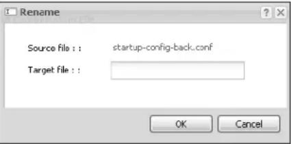 Specify the new name for the configuration file. Use up to 25 characters (including a-zA-Z0-9;~!@#%^&()_+[]',=-.Click OK to save the duplicate or click Cancel to close the screen without saving a duplicate of the configuration file. Specify the new name for the configuration file. Use up to 25 characters (including a-zA-Z0-9;~!@#%^&()_+[]',=-.Click OK to save the duplicate or click Cancel to close the screen without saving a duplicate of the configuration file. | |
| Remove | Click a configuration file's row to select it and click Remove to delete it from the device. You can only delete manually saved configuration files. You cannot delete the system-default.conf, startup-config.conf and lastgood.conf files.A pop-up window asks you to confirm that you want to delete the configuration file. Click OK to delete the configuration file or click Cancel to close the screen without deleting the configuration file. |
| Download | Click a configuration file's row to select it and click Download to save the configuration to your computer. |
| Copy | Use this button to save a duplicate of a configuration file on the device.Click a configuration file's row to select it and click Copy to open the Copy File screen. Specify a name for the duplicate configuration file. Use up to 25 characters (including a-zA-Z0-9;~!@#%^&()_+[]{}',=-.Click OK to save the duplicate or click Cancel to close the screen without saving a duplicate of the configuration file. Specify a name for the duplicate configuration file. Use up to 25 characters (including a-zA-Z0-9;~!@#%^&()_+[]{}',=-.Click OK to save the duplicate or click Cancel to close the screen without saving a duplicate of the configuration file. |
| Apply Use this button to have the device use a specific configuration file.Click a configuration file's row to select it and clickApplyto have the device use that configuration file. The device does not have to restart in order to use a different configuration file, although you will need to wait for a few minutes while the system reconfigures.The following screen gives you options for what the device is to do if it encounters an error in the configuration file. | |
| Apply Configuration FileFile Name:system-default.confIf applying the configuration file encounters an error:Immediately stop applying the configuration fileImmediately stop applying the configuration file and roll back to the previous configurationIgnore errors and finish applying the configuration fileIgnore errors and finish applying the configuration file and then roll back to the previous configurationOK Cancel | |
| Immediately stop applying the configuration file- this is not recommended because it would leave the rest of the configuration blank. If the interfaces were not configured before the first error, the console port may be the only way to access the device.Immediately stop applying the configuration file and roll back to the previous configuration- this gets the device started with a fully valid configuration file as quickly as possible.Ignore errors and finish applying the configuration file- this applies the valid parts of the configuration file and generates error logs for all of the configuration file's errors. This lets the device apply most of your configuration and you can refer to the logs for what to fix.Ignore errors and finish applying the configuration file and then roll back to the previous configuration- this applies the valid parts of the configuration file, generates error logs for all of the configuration file's errors, and starts the device with a fully valid configuration file.Click OK to have the device start applying the configuration file or click Cancel to close the screen | |
| # | This column displays the number for each configuration file entry. This field is a sequential value, and it is not associated with a specific address. The total number of configuration files that you can save depends on the sizes of the configuration files and the available flash storage space. |
| File Name This column displays the label that identifies a configuration file. | |
| Size This column displays the size (in KB) of a configuration file. | |
| Last Modified | This column displays the date and time that the individual configuration files were last changed or saved. |
| Upload Configuration File | The bottom part of the screen allows you to upload a new or previously saved configuration file from your computer to your deviceYou cannot upload a configuration file named system-default.conf or lastgood.conf.If you upload startup-config.conf, it will replace the current configuration and immediately apply the new settings. |
| File Path | Type in the location of the file you want to upload in this field or click Browse ... to find it. |
| Browse... | Click Browse... to find the .conf file you want to upload. The configuration file must use a ".conf" filename extension. You will receive an error message if you try to upload a file of a different format. Remember that you must decompress compressed (.zip) files before you can upload them. |
| Upload | Click Upload to begin the upload process. This process may take up to two minutes. |
17.3 Firmware Package
Click Maintenance > File Manager > Firmware Package to open this screen. Use the Firmware Package screen to check your current firmware version and upload firmware to the device.
Note: The Web Configurator is the recommended method for uploading firmware. You only need to use the command line interface if you need to recover the firmware. See the CLI Reference Guide for how to determine if you need to recover the firmware and how to recover it.
Find the firmware package at www.zyxel.com in a file that (usually) uses a .bin extension.
The firmware update can take up to five minutes. Do not turn off or reset the device while the firmware update is in progress!
Figure 109 Maintenance > File Manager > Firmware Package

text_image
Configuration File Firmware Package Shell Script Version Boot Module: 1.13 Current Version: 2.23(UJA.0)b2 Released Date: 2010-11-24 10:58:37 Upload File To upload firmware package, browse to the location of the file and then click Upload. File Path: Browse... UploadThe following table describes the labels in this screen.
Table 89 Maintenance > File Manager > Firmware Package
| LABEL DESCRIPTION | |
| Boot Module | This is the version of the boot module that is currently on the device. |
| Current Version | This is the firmware version and the date created. |
| Released Date | This is the date that the version of the firmware was created. |
| File Path | Type in the location of the file you want to upload in this field or click Browse ... to find it. |
| Browse... | Click Browse... to find the .bin file you want to upload. Remember that you must decompress compressed (.zip) files before you can upload them. |
| Upload | Click Upload to begin the upload process. This process may take up to two minutes. |
After you see the Firmware Upload in Process screen, wait two minutes before logging into the device again.
Note: The device automatically reboots after a successful upload.
The device automatically restarts causing a temporary network disconnect. In some operating systems, you may see the following icon on your desktop.
Figure 110 Network Temporarily Disconnected

text_image
Local Area Connection Network cable unpluggedAfter five minutes, log in again and check your new firmware version in the Dashboard screen.
17.4 Shell Script
Use shell script files to have the device use commands that you specify. Use a text editor to create the shell script files. They must use a ".zysh" filename extension.
Click Maintenance > File Manager > Shell Script to open this screen. Use the Shell Script screen to store, name, download, upload and run shell script files. You can store multiple shell script files on the device at the same time.
Note: You should include write commands in your scripts. If you do not use the write command, the changes will be lost when the device restarts. You could use multiple write commands in a long script.
Figure 111 Maintenance > File Manager > Shell Script

text_image
Configuration File Firmware Package Shell Script Shell Scripts Rename Remove Download Copy ApplyFile Name Size Last Modified
Page 1 of 1 Show 50 items No data to display Upload Shell Script To upload a shell script, browse to the location of the file (.zysh) and then click Upload. File Path: Browse... UploadEach field is described in the following table.
Table 90 Maintenance > File Manager > Shell Script
| LABEL DESCRIPTION | |
| Rename | Use this button to change the label of a shell script file on the device.You cannot rename a shell script to the name of another shell script in the device.Click a shell script's row to select it and clickRenameto open theRename File screen.Specify the new name for the shell script file. Use up to 25 characters (including a-zA-Z0-9;~!@#%^&()_+[] ',= -).ClickOKto save the duplicate or clickCancelto close the screen without saving a duplicate of the configuration file. |
| Remove | Click a shell script file's row to select it and clickDeleteto delete the shell script file from the device.A pop-up window asks you to confirm that you want to delete the shell script file. ClickOKto delete the shell script file or clickCancelto close the screen without deleting the shell script file. |
| Download | Click a shell script file's row to select it and clickDownloadto save the configuration to your computer. |
| CopyRun | Use this button to save a duplicate of a shell script file on the device.Click a shell script file's row to select it and clickCopyto open theCopy Filescreen.Specify a name for the duplicate file. Use up to 25 characters (including a-zA-Z0-9;~!@#%^&()_+[]{{ }',= -).ClickOKto save the duplicate or clickCancelto close the screen without saving a duplicate of the configuration file.Use this button to have the device use a specific shell script file.Click a shell script file's row to select it and click Run to have the device use that shell script file. You may need to wait awhile for the device to finish applying the commands. |
| # | This column displays the number for each shell script file entry. |
| File Name This column displays the label that identifies a shell script file. | |
| Size This column displays the size (in KB) of a shell script file. | |
| Last Modified | This column displays the date and time that the individual shell script files were last changed or saved. |
| Upload Shell Script | The bottom part of the screen allows you to upload a new or previously saved shell script file from your computer to your device. |
| File Path | Type in the location of the file you want to upload in this field or click Browse ... to find it. |
| Browse... | Click Browse... to find the .zysh file you want to upload. |
| Upload | Click Upload to begin the upload process. This process may take up to several minutes. |
18.1 Overview
Use the diagnostics screens for troubleshooting.
18.1.1 What You Can Do in this Chapter
- The Diagnostics screen (Section 18.2 on page 229) generates a file containing the device's configuration and diagnostic information if you need to provide it to customer support during troubleshooting.
- The Packet Capture screen (Section 18.3 on page 230) captures data packets going through the device.
- The Wireless Frame Capture screens (Section 18.4 on page 233) capture network traffic going through the AP interfaces connected to your device.
18.2 Diagnostics
This screen provides an easy way for you to generate a file containing the device's configuration and diagnostic information. You may need to generate this file and send it to customer support during troubleshooting.
Click Maintenance > Diagnostics to open the Diagnostic screen.
Figure 112 Maintenance > Diagnostics

text_image
Diagnostics Packet Capture Wireless Frame Capture Diagnostic Information Collector Filename: none Last modified: none Size: none Collect Now DownloadThe following table describes the labels in this screen.
Table 91 Maintenance > Diagnostics
| LABEL DESCRIPTION | |
| Filename This is the name of the most recently created diagnostic file. | |
| Last modified This is the date and time that the last diagnostic file was created. The format is yyyy-mm-dd hh:mm:ss. | |
| Size This is the size of the most recently created diagnostic file. | |
| Collect Now Click this to have the device create a new diagnostic file. | |
| Download Click this to save the most recent diagnostic file to a computer. | |
18.3 Packet Capture
Use this screen to capture network traffic going through the device's interfaces. Studying these packet captures may help you identify network problems.
Click Maintenance > Diagnostics > Packet Capture to open the packet capture screen.
Note: New capture files overwrite existing files of the same name. Change the File Suffix field's setting to avoid this.
Figure 113 Maintenance > Diagnostics > Packet Capture > Capture

text_image
Diagnostics Packet Capture Wireless Frame Capture Capture Files Interfaces Available Interfaces lan Capture Interfaces Filter IP Version: any Protocol Type: any Host IP: any Host Port: 0 (0: any) Misc setting File Size: 1000 Kbytes Duration: 0 (0: unlimited) File Suffix: packet-capture Number Of Bytes To Capture (Per Packet): 1500 Bytes Capture Stop ResetThe following table describes the labels in this screen.
Table 92 Maintenance > Diagnostics > Packet Capture
| LABEL DESCRIPTION | |
| Interfaces | Enabled interfaces (except for virtual interfaces) appear under Available Interfaces. Select interfaces for which to capture packets and click the right arrow button to move them to the Capture Interfaces list. Use the [Shift] and/or [Ctrl] key to select multiple objects. |
| IP Type | Select the protocol of traffic for which to capture packets. Select any to capture packets for all types of traffic. |
| Host IP | Select a host IP address object for which to capture packets. Select any to capture packets for all hosts. Select User Defined to be able to enter an IP address. |
| Host Port | This field is configurable when you set the IP Type to any, tcp, or udp. Specify the port number of traffic to capture. |
| File Size Specify a maximum size limit in kilobytes for the total combined size of all the capture files on the device, including any existing capture files and any new capture files you generate.Note: If you have existing capture files you may need to set this size larger or delete existing capture files.The valid range is 1 to 10000. The device stops the capture and generates the capture file when either the file reaches this size or the time period specified in the Duration field expires. | |
| Duration Set a time limit | in seconds for the capture. The device stops the capture and generates the capture file when either this period of time has passed or the file reaches the size specified in the File Size field. 0 means there is no time limit. |
| File Suffix Specify text to | add to the end of the file name (before the dot and filename extension) to help you identify the packet capture files. Modifying the file suffix also avoids making new capture files that overwrite existing files of the same name.The file name format is “interface name-file suffix.cap”, for example “lan-packet-capture.cap”. |
| Number Of Bytes To Capture (Per Packet) | Specify the maximum number of bytes to capture per packet. The device automatically truncates packets that exceed this size. As a result, when you view the packet capture files in a packet analyzer, the actual size of the packets may be larger than the size of captured packets. |
| Capture Click this button | to have the device capture packets according to the settings configured in this screen.You can configure the device while a packet capture is in progress although you cannot modify the packet capture settings.The device’s throughput or performance may be affected while a packet capture is in progress.After the device finishes the capture it saves a separate capture file for each selected interface. The total number of packet capture files that you can save depends on the file sizes and the available flash storage space. Once the flash storage space is full, adding more packet captures will fail. |
| Stop Click this button to | stop a currently running packet capture and generate a separate capture file for each selected interface. |
| Reset Click this button to | return the screen to its last-saved settings. |
18.3.1 Packet Capture Files
Click Maintenance > Diagnostics > Packet Capture > Files to open the packet capture files screen. This screen lists the files of packet captures the device has performed. You can download the files to your computer where you can study them using a packet analyzer (also known as a network or protocol analyzer) such as Wireshark.
Figure 114 Maintenance > Diagnostics > Packet Capture > Files

text_image
Diagnostics Packet Capture Wireless Frame Capture Capture Files Captured Packet Files Remove Download # File Name Size Last Modified Page 1 of 1 Show 50 items No data to displayThe following table describes the labels in this screen.
Table 93 Maintenance > Diagnostics > Packet Capture > Files
| LABEL DESCRIPTION | |
| Remove | Select files and click Remove to delete them from the device. Use the [Shift] and/or [Ctrl] key to select multiple files. A pop-up window asks you to confirm that you want to delete. |
| Download | Click a file to select it and click Download to save it to your computer. |
| # This column | displays the number for each packet capture file entry. The total number of packet capture files that you can save depends on the file sizes and the available flash storage space. |
| File Name | This column displays the label that identifies the file. The file name format is interface name-file suffix.cap. |
| Size This column | in displays the size (in bytes) of a configuration file. |
| Last Modified | This column displays the date and time that the individual files were saved. |
18.3.2 Example of Viewing a Packet Capture File
Here is an example of a packet capture file viewed in the Wireshark packet analyzer. Notice that the size of frame 15 on the wire is 1514 bytes while the captured size is only 1500 bytes. The device
truncated the frame because the capture screen's Number Of Bytes To Capture (Per Packet) field was set to 1500 bytes.
Figure 115 Packet Capture File Example

text_image
lan1-packel-capture.cap - Wireshark File Edit View Go Capture Analyze Statistics Telephony Tools Help Filter: Expression... Clear Apply No. . Time Source Destination Protocol Info 1 0.000000 172.16.1.1 172.16.1.33 TLSv1 Application Da 2 0.000744 172.16.1.1 172.16.1.33 TLSv1 Encrypted Aler 3 0.001246 172.16.1.1 172.16.1.33 TCP https > rmsigg 4 0.002448 172.16.1.33 172.16.1.1 TCP rmsigport > ht 5 0.002680 172.16.1.33 172.16.1.1 TCP rmsigport > ht 6 0.002939 172.16.1.33 172.16.1.1 TLSv1 Encrypted Aler 7 0.003106 172.16.1.33 172.16.1.1 TCP rmsigport > ht 8 0.003494 172.16.1.1 172.16.1.33 TCP https > rmsigg 9 0.065938 172.16.1.33 172.16.1.1 TCP rmlnk > https 10 0.066503 172.16.1.1 172.16.1.33 TCP https > rmlnk 11 0.066840 172.16.1.33 172.16.1.1 TCP rmlnk > https 12 0.067182 172.16.1.33 172.16.1.1 SSL client Hello 13 0.067591 172.16.1.1 172.16.1.33 TCP https > rmlnk 14 0.070900 172.16.1.1 172.16.1.33 TLSv1 server Hello, 15 0.072055 172.16.1.33 172.16.1.1 TLSv1 charge cipher 16 0.072077 172.16.1.33 172.16.1.1 TLSv1 Ignored Unknow 17 0.072944 172.16.1.1 172.16.1.33 TCP https > rmlnk Frame 15 (1514 bytes on wire, 1500 bytes captured) Ethernet TL Src: G-ProCom_le:4a:eo (00:0f:fe:he:4a:eo), Dst: ZyxelCom_00:30:59 (00:13:49:00:30:59) Internet Protocol, Src: 172.16.1.33 (172.16.1.33), Dst: 172.16.1.1 (172.16.1.1) Transmission Control Protocol, Src Port: rmlnk (2818), Dst Port: https (443), Seq: 173, Ack: 139, Len Secure Socket Layer [Unreassembled Packet: SSL] 0000 00 13 49 00 30 59 00 Cf fe le 4a e0 08 00 45 00 ..I.OY.. ..J..E. 0010 05 dc 40 71 40 00 80 c6 5a 68 ac 10 oI zI ac 10 ..&q@.. zh..!.. 0020 0i 0i 0b 02 0i bb bO 37 a8 2a 6e 79 fc aI 5D 5D ......7 .*ny..P.. 0030 Ff 75 89 dd 00 00 14 c3 oI dO oI cI e Oc oI oI oI u..C..Gr .... 0040 Bb e2 b3 dI dI dI dI dI dI dI dI dI dI dI dI dI dI dI dI dI dI dI dI dI dI dI dI dI dI dI dI dI dI dI dI dI dI dI dI dI dI dI dI dI dI dI dI dI dI dI dI dI dI dII TSSv TSSv TSSv TSSv TSSv TSSv TSSv TSSv TSSv TSSv TSSv TSSv TSSv TSSv TSSv TSSv TSSv TSSv TSSv TSSv TSSv TSSv TSSv TSSv TSSv TSSs TSSs TSSs TSSs TSSs TSSs TSSs TSSs TSSs TSSs TSSs TSSs TSSs TSSs TSSs TSSs TSSs TSSs TSSs TSSs TSSs TSSs TSSs TSSs TSSs TSSt TSSt TSSt TSSt TSSt TSSt TSSt TSSt TSSt TSSt TSSt TSSt TSSt TSSt TSSt TSSt TSSt TSSt TSSt TSSt TSSt TSSt TSSt TSSt TSSt TSSs TSSs TSSs TSSs TSSs TSSs TSSs TSSs TSSs TSSs TSSs TSSs TSSs TSSs TSSs TSSs TSSs TSSs TSSs TSSs TSSs TSSs TSSs TSSs TSSss TSSss TSSss TSSss TSSss TSSss TSSss TSSss TSSss TSSss TSSss TSSss TSSss TSSss TSSss TSSss TSSss18.4 Wireless Frame Capture
Use this screen to capture wireless network traffic going through the AP interfaces connected to your device. Studying these frame captures may help you identify network problems.
Click Maintenance > Diagnostics > Wireless Frame Capture to display this screen.
Note: New capture files overwrite existing files of the same name. Change the File Suffix field's setting to avoid this.
Figure 116 Maintenance > Diagnostics > Wireless Frame Capture > Capture

text_image
Diagnostics Packet Capture Wireless Frame Capture Capture Files MON Mode APs Configure AP to MON Mode Available MON Mode APs Capture MON Mode APs Misc Setting File Size: 1000 Kbytes File Prefix: monitorThe following table describes the labels in this screen.
Table 94 Maintenance > Diagnostics > Wireless Frame Capture > Capture
| LABEL DESCRIPTION | |
| AP Operating Mode | This section appears when the device is set to the standalone AP mode. |
| Wireless Radio 1 operating mode | This field shows whether the radio is set to function as an AP or a monitor. |
| Please configure at least one radio to MON mode. | Click this to go theConfiguration > Wireless > AP Management screen, where you can set a radio to monitor mode. |
| MON Mode APs This sect | on appears when the device is set to the controller mode. |
| Configure AP to MON Mode | Click this to go theConfiguration > Wireless > AP Management screen, where you can set one or more APs to monitor mode. |
| Available MON Mode APs | This column displays which APs on your wireless network are currently configured for monitor mode.Use the arrow buttons to move APs off this list and onto theCaptured MON Mode APs list. |
| Capture MON Mode APs | This column displays the monitor-mode configured APs selected to for wireless frame capture. |
| Misc Setting | |
| File Size Specify a max | maximum size limit in kilobytes for the total combined size of all the capture files on the device, including any existing capture files and any new capture files you generate.Note: If you have existing capture files you may need to set this size larger or delete existing capture files.The valid range is 1 to 50000. The device stops the capture and generates the capture file when either the file reaches this size or the time period specified in theDurationfield expires. |
| File Prefix | Specify text to add to the front of the file name in order to help you identify frame capture files.You can modify the prefix to also create new frame capture files each time you perform a frame capture operation. Doing this does no overwrite existing frame capture files.The file format is: [file prefix].dump. For example, “monitor.dump”. |
| Capture Click this button | to have the device capture frames according to the settings configured in this screen.You can configure the device while a frame capture is in progress although you cannot modify the frame capture settings.The device’s throughput or performance may be affected while a frame capture is in progress.After the device finishes the capture it saves a combined capture file for all APs. The total number of frame capture files that you can save depends on the file sizes and the available flash storage space. Once the flash storage space is full, adding more frame captures will fail. |
| Stop | Click this button to stop a currently running frame capture and generate a combined capture file for all APs. |
| Reset Click this button to | return the screen to its last-saved settings. |
18.4.1 Wireless Frame Capture Files
Click Maintenance > Diagnostics > Wireless Frame Capture > Files to open this screen. This screen lists the files of wireless frame captures the device has performed. You can download the files to your computer where you can study them using a packet analyzer (also known as a network or protocol analyzer) such as Wireshark.
Figure 117 Maintenance > Diagnostics > Wireless Frame Capture > Files

text_image
Diagnostics Packet Capture Wireless Frame Capture Capture Files Captured Packet Files Remove Download # File Name Size Last Modified Page 1 of 1 Show 50 items No data to displayThe following table describes the labels in this screen.
Table 95 Maintenance > Diagnostics > Wireless Frame Capture > Files
| LABEL DESCRIPTION | |
| Remove | Select files and click Remove to delete them from the device. Use the [Shift] and/or [Ctrl] key to select multiple files. A pop-up window asks you to confirm that you want to delete. |
| Download | Click a file to select it and click Download to save it to your computer. |
| # This column | displays the number for each packet capture file entry. The total number of packet capture files that you can save depends on the file sizes and the available flash storage space. |
| File Name | This column displays the label that identifies the file. The file name format is interface name-file suffix.cap. |
| Size This column | in displays the size (in bytes) of a configuration file. |
| Last Modified | This column displays the date and time that the individual files were saved. |
19.1 Overview
Use this to restart the device.
19.1.1 What You Need To Know
If you applied changes in the Web configurator, these were saved automatically and do not change when you reboot. If you made changes in the CLI, however, you have to use the write command to save the configuration before you reboot. Otherwise, the changes are lost when you reboot.
Reboot is different to reset; reset returns the device to its default configuration.
19.2 Reboot
This screen allows remote users can restart the device. To access this screen, click Maintenance > Reboot.
Figure 118 Maintenance > Reboot

text_image
Reboot Reboot Click the Reboot button to reboot the device. Please wait a few minutes until the login screen appears. If the login screen does not appear, type the IP address of the device in your Web browser. RebootClick the Reboot button to restart the device. Wait a few minutes until the login screen appears. If the login screen does not appear, type the IP address of the device in your Web browser.
You can also use the CLI command reboot to restart the device.
20.1 Overview
Use this screen to shutdown the device.
Always use Maintenance > Shutdown > Shutdown or the shutdown command before you turn off the device or remove the power. Not doing so can cause the firmware to become corrupt.
20.1.1 What You Need To Know
Shutdown writes all cached data to the local storage and stops the system processes. Shutdown is different to reset; reset returns the device to its default configuration.
20.2 Shutdown
To access this screen, click Maintenance > Shutdown.
Figure 119 Maintenance > Shutdown

text_image
Shutdown Shutdown Click the "Shutdown" button to shutdown the device. ShutdownClick the Shutdown button to shut down the device. Wait for the device to shut down before you manually turn off or remove the power. It does not turn off the power.
You can also use the CLI command shutdown to shutdown the device.
Troubleshooting
21.1 Overview
This chapter offers some suggestions to solve problems you might encounter. The potential problems are divided into the following categories.
• Power, Hardware Connections, and LEDs
• device Access and Login
- Internet Access
• Wireless AP Troubleshooting
- Resetting the device
21.2 Power, Hardware Connections, and LEDs
The device does not turn on. None of the LEDs turn on.
1 Make sure you are using the power adaptor included with the device or a PoE power injector.
2 Make sure the power adaptor or PoE power injector is connected to the device and plugged in to an appropriate power source. Make sure the power source is turned on.
3 Disconnect and re-connect the power adaptor or PoE power injector.
4 Inspect your cables for damage. Contact the vendor to replace any damaged cables.
5 If none of these steps work, you may have faulty hardware and should contact your device vendor.
One of the LEDs does not behave as expected.
1 Make sure you understand the normal behavior of the LED. See Section 1.7 on page 25.
2 Check the hardware connections. See the Quick Start Guide.
3 Inspect your cables for damage. Contact the vendor to replace any damaged cables.
4 Disconnect and re-connect the power adaptor or PoE power injector to the device.
5 If the problem continues, contact the vendor.
21.3 device Access and Login
I forgot the IP address for the device.
1 The default IP address is 192.168.1.2.
2 Use the commands through the console port to check the IP address. Connect your computer to the CONSOLE port using a console cable. Your computer should have a terminal emulation communications program (such as HyperTerminal) set to VT100 terminal emulation, no parity, 8 data bits, 1 stop bit, no flow control and 115200 bps port speed.
3 If this does not work, you have to reset the device to its factory defaults. See Section 21.6 on page 249.
I cannot see or access the Login screen in the web configurator.
1 Make sure you are using the correct IP address.
• The default IP address is 192.168.1.2.
- If you changed the IP address, use the new IP address.
- If you changed the IP address and have forgotten it, see the troubleshooting suggestions for I forgot the IP address for the device.
2 Check the hardware connections, and make sure the LEDs are behaving as expected. See the Quick Start Guide and Section 1.7 on page 25.
3 Make sure your Internet browser does not block pop-up windows and has JavaScripts and Java enabled.
4 Make sure your computer is in the same subnet as the device. (If you know that there are routers between your computer and the device, skip this step.)
- If there is no DHCP server on your network, make sure your computer's IP address is in the same subnet as the device.
5 Reset the device to its factory defaults, and try to access the device with the default IP address. See your Quick Start Guide.
6 If the problem continues, contact the network administrator or vendor, or try one of the advanced suggestions.
Advanced Suggestions
- Try to access the device using another service, such as Telnet. If you can access the device, check the remote management settings to find out why the device does not respond to HTTP.
- If your computer is connected wirelessly, use a computer that is connected to a LAN/ETHERNET port.
- If you've forgotten the device's IP address, you can use the commands through the console port to check it. Connect your computer to the CONSOLE port using a console cable. Your computer should have a terminal emulation communications program (such as HyperTerminal) set to VT100 terminal emulation, no parity, 8 data bits, 1 stop bit, no flow control and 115200 bps port speed.
I forgot the password.
1 The default password is 1234.
2 If this does not work, you have to reset the device to its factory defaults. See Section 21.6 on page 249.
I can see the Login screen, but I cannot log in to the device.
1 Make sure you have entered the user name and password correctly. The default password is 1234. This fields are case-sensitive, so make sure [Caps Lock] is not on.
2 You cannot log in to the web configurator while someone is using Telnet to access the device. Log out of the device in the other session, or ask the person who is logged in to log out.
3 Disconnect and re-connect the power adaptor or PoE power injector to the device.
4 If this does not work, you have to reset the device to its factory defaults. See Section 21.6 on page 249.
I cannot access the device via the console port.
1 Check to see if the device is connected to your computer's console port.
2 Check to see if the communications program is configured correctly. The communications software should be configured as follows:
VT100 terminal emulation.
115200 bps is the default speed on leaving the factory. Try other speeds in case the speed has been changed.
No parity, 8 data bits, 1 stop bit, data flow set to none.
I cannot use FTP to upload / download the configuration file. / I cannot use FTP to upload new firmware.
See the troubleshooting suggestions for I cannot see or access the Login screen in the web configurator. Ignore the suggestions about your browser.
21.4 Internet Access
I cannot access the Internet.
1 Check the hardware connections, and make sure the LEDs are behaving as expected. See the Quick Start Guide and Section 21.2 on page 241.
2 Make sure you entered your ISP account information correctly. These fields are case-sensitive, so make sure [Caps Lock] is not on.
3 If you are trying to access the Internet wirelessly, make sure the wireless settings on the wireless client are the same as the settings on the AP.
4 Disconnect all the cables from your device, and follow the directions in the Quick Start Guide again.
5 If the problem continues, contact your ISP.
I cannot access the Internet anymore. I had access to the Internet (with the device), but my Internet connection is not available anymore.
1 Check the hardware connections, and make sure the LEDs are behaving as expected. See the Quick Start Guide and Section 1.7 on page 25.
2 Reboot the device.
3 If the problem continues, contact your ISP.
The Internet connection is slow or intermittent.
1 There might be a lot of traffic on the network. Look at the LEDs, and check Section 1.7 on page 25. If the device is sending or receiving a lot of information, try closing some programs that use the Internet, especially peer-to-peer applications.
2 Check the signal strength. If the signal is weak, try moving the device closer to the AP (if possible), and look around to see if there are any devices that might be interfering with the wireless network (microwaves, other wireless networks, and so on).
3 Reboot the device.
4 If the problem continues, contact the network administrator or vendor, or try one of the advanced suggestions.
Advanced Suggestions
Check the settings for QoS. If it is disabled, you might consider activating it. If it is enabled, you might consider raising or lowering the priority for some applications.
21.5 Wireless AP Troubleshooting
I cannot access the device or ping any computer from the WLAN.
1 Make sure the wireless LAN is enabled on the device
2 Make sure the wireless adapter on the wireless station is working properly.
3 Make sure the wireless adapter (installed on your computer) is IEEE 802.11 compatible and supports the same wireless standard as the device.
4 Make sure your computer (with a wireless adapter installed) is within the transmission range of the device.
5 Check that both the device and your wireless station are using the same wireless and wireless security settings.
6 Make sure traffic between the WLAN and the LAN is not blocked by the firewall on the device.
7 Make sure you allow the device to be remotely accessed through the WLAN interface. Check your remote management settings.
Hackers have accessed my WEP-encrypted wireless LAN.
WEP is extremely insecure. Its encryption can be broken by an attacker, using widely-available software. It is strongly recommended that you use a more effective security mechanism. Use the strongest security mechanism that all the wireless devices in your network support. WPA2 or WPA2-PSK is recommended.
The wireless security is not following the re-authentication timer setting I specified.
If a RADIUS server authenticates wireless stations, the re-authentication timer on the RADIUS server has priority. Change the RADIUS server's configuration if you need to use a different re-authentication timer setting.
Device HA is not working.
- You may need to disable STP (Spanning Tree Protocol).
- The master and its backups must all use the same device HA mode (active-passive).
- Configure a static IP address for each interface that you will have device HA monitor.
- Configure a separate management IP address for each interface. You can use it to access the device for management whether the device is the master or a backup. The management IP address should be in the same subnet as the interface IP address.
- Enable monitoring for the same interfaces on the master and backup devices.
- Each monitored interface must have a static IP address and be connected to the same subnet as the corresponding interface on the backup or master device.
- If you have multiple device virtual routers on your network, use a different cluster ID to identify each virtual router. There can only be one master device in each virtual router (same cluster ID).
A broadcast storm results when I turn on Device HA.
Do not connect the bridge interfaces on two devices without device HA activated on both. Either activate device HA before connecting the bridge interfaces or disable the bridge interfaces, connect the bridge interfaces, activate device HA, and finally reactivate the bridge interfaces.
I cannot get the Device HA synchronization to work.
Only devices of the same model and firmware version can synchronize.
I cannot get a certificate to import into the device.
1 For My Certificates, you can import a certificate that matches a corresponding certification request that was generated by the device. You can also import a certificate in PKCS# 12 format, including the certificate's public and private keys.
2 You must remove any spaces from the certificate's filename before you can import the certificate.
3 Any certificate that you want to import has to be in one of these file formats:
- Binary X.509: This is an ITU-T recommendation that defines the formats for X.509 certificates.
- PEM (Base-64) encoded X.509: This Privacy Enhanced Mail format uses lowercase letters, uppercase letters and numerals to convert a binary X.509 certificate into a printable form.
- Binary PKCS#7: This is a standard that defines the general syntax for data (including digital signatures) that may be encrypted. A PKCS #7 file is used to transfer a public key certificate. The private key is not included. The device currently allows the importation of a PKS#7 file that contains a single certificate.
- PEM (Base-64) encoded PKCS# 7: This Privacy Enhanced Mail (PEM) format uses lowercase letters, uppercase letters and numerals to convert a binary PKCS# 7 certificate into a printable form.
- Binary PKCS# 12: This is a format for transferring public key and private key certificates. The private key in a PKCS # 12 file is within a password-encrypted envelope. The file's password is not connected to your certificate's public or private passwords. Exporting a PKCS # 12 file creates this and you must provide it to decrypt the contents when you import the file into the device.
Note: Be careful not to convert a binary file to text during the transfer process. It is easy for this to occur since many programs use text files by default.
I can only see newer logs. Older logs are missing.
When a log reaches the maximum number of log messages, new log messages automatically overwrite existing log messages, starting with the oldest existing log message first.
The commands in my configuration file or shell script are not working properly.
- In a configuration file or shell script, use “#” or “!” as the first character of a command line to have the device treat the line as a comment.
- Your configuration files or shell scripts can use "exit" or a command line consisting of a single "!" to have the device exit sub command mode.
- Include write commands in your scripts. Otherwise the changes will be lost when the device restarts. You could use multiple write commands in a long script.
Note: “exit” or “!” must follow sub commands if it is to make the device exit sub command mode.
I cannot get the firmware uploaded using the commands.
The Web Configurator is the recommended method for uploading firmware. You only need to use the command line interface if you need to recover the firmware. See the CLI Reference Guide for how to determine if you need to recover the firmware and how to recover it.
My packet capture captured less than I wanted or failed.
The packet capture screen's File Size sets a maximum size limit for the total combined size of all the capture files on the device, including any existing capture files and any new capture files you
generate. If you have existing capture files you may need to set this size larger or delete existing capture files.
The device stops the capture and generates the capture file when either the capture files reach the File Size or the time period specified in the Duration field expires.
My earlier packet capture files are missing.
New capture files overwrite existing files of the same name. Change the File Suffix field's setting to avoid this.
Wireless clients cannot connect to an AP.
- There may be a configuration mismatch between the wireless clients and the AP, or an incorrect VLAN topology. See Chapter 4 on page 49 for a simple primer on basic network topology and management.
- The wireless client's MAC address may be on the MAC filtering list. See Section 12.3.3 on page 147 for details on managing the device MAC Filter.
- The wireless client may not be able to get an IP:
Check the wireless client's own network configuration settings to ensure that it is set up to receive its IP address automatically.
If the device or a connected Internet access device are managing the network with static IPs, make sure that the server settings for issuing those IPs are properly configured.
Check the wireless client's own network settings to ensure it is already set up with its static IP address.
- Authentication of the wireless client with the authentication server may have failed. Ensure the AP profile assigned to the AP uses a security profile that is properly configured and which is matches the security settings in use by the device. For example, if the security mode on the AP is set to WPA/WPA2 then make sure the authentication server is running and able to complete the 802.1x authentication sequence. See Chapter 12 on page 135 and Section 15.10 on page 200 for more.
- If you cannot solve the problem on your own, before contacting Customer Support use the built-in wireless frame capture tools (Chapter 18 on page 229) to capture data that can be used for more granular troubleshooting procedures. To use the built-in wireless frame capture tool, first set up a second device nearby to act as a Monitor AP (Chapter 9 on page 101).
The AP status is registered as offline even though it is on.
- Check the network connections between the device and the AP to ensure they are still intact.
- The AP may be suffering from instability. Disconnect it to turn its power off, wait some time, then reconnect it and see if that resolves the issue.
- The CAPWAP daemon may be down. Use the device's built-in diagnostic tools and CLI console to get CAPWAP debug messages which can later be sent to customer service for analysis.
Wireless clients are not being load balanced among my APs.
- Make sure that all the APs used by the wireless clients in question share the same SSID, security, and radio settings.
- Make sure that all the APs are in the same broadcast domain.
- Make sure that the wireless clients are in range of the other APs; if they are only in range of a single AP, then load balancing may not be as effective.
In the Monitor > Wireless > AP Information > Radio List page, there is no load balancing indicator associated with any APs assigned to the load balancing task.
- Check to be sure that the AP profile which contains the load balancing settings is correctly assigned to the APs in question.
- The load balancing task may have been terminated because further load balancing on the APs in question is no longer required.
21.6 Resetting the device
If you cannot access the device by any method, try restarting it by turning the power off and then on again. If you still cannot access the device by any method or you forget the administrator password(s), you can reset the device to its factory-default settings. Any configuration files or shell scripts that you saved on the device should still be available afterwards.
Use the following procedure to reset the device to its factory-default settings. This overwrites the settings in the startup-config.conf file with the settings in the system-default.conf file.
Note: This procedure removes the current configuration.
1 Make sure the PWR\ SYS LED is on and not blinking.
2 Press the RESET button and hold it until the PWR\ SYS LED begins to blink. (This usually takes about five seconds.)
3 Release the RESET button, and wait for the device to restart.
You should be able to access the device using the default settings.
21.7 Getting More Troubleshooting Help
Search for support information for your model at www.zyxel.com for more troubleshooting suggestions.
Product Specifications
The following tables summarize the device's hardware and firmware features.
Table 96 Hardware Specifications
| Power Specification 12 V | DC, 1.5 A |
| Reset button Returns all settings to their factory defaults. | |
| Ethernet Port Gigabit Ethernet, full duplex, RJ-45 connectors, auto-negotiating, auto-MDI/MDIX (auto-crossover, uses either crossover or straight-through Ethernet cables). | |
| Power over Ethernet (PoE) | IEEE 802.3at compliant, backwards compatible to 802.3af |
| Console Port One PS-2 console port | |
| Antenna 2 reverse SMA antenna connectors2 external dipole antennas,Gain: 2 dBi | |
| Output Power IEEE 802.11a: 5150-5250Using single antenna: 12dBmIEEE 802.11a: 5250 - 5850Using single antenna:18dbmIEEE 802.11bUsing single antenna: 17dBmIEEE 802.11gUsing single antenna: 14dBmIEEE 802.11gn: HT20Using single antenna: 12.5dBmUsing three antennas: 17dBmIEEE 802.11gn: HT40Using single antenna: 8.5 dBmUsing three antennas: 13 dBmIEEE 802.11an: HT20 / HT40 5150-5250Using single antenna: 7.5 dBmUsing three antennas: 12 dBmIEEE 802.11an: HT20 / HT40 5250 - 5850Using single antenna: 13.5 dBmUsing three antennas: 18 dBm | |
| Theft Prevention Kengsinton slot | |
| Operating Temperature 0 ~ 40 °C | |
| Storage Temperature -30 ~ 70 °C | |
| Operating Humidity 10 ~ 90 % (non-condensing) | |
Table 96 Hardware Specifications
| Storage Humidity 10 ~ 90 % (non-condensing) | |
| Dimensions 198.5 mm (L) x 138.5mm (W) x 47.5mm (H) | |
| Weight 450 g | |
| Distance between the centers of wall-mounting holes on the device's back. | 140 mm |
| Screw size for wall-mounting | M4 Tap Screw. See Figure 121 on page 254 for details. |
| Plenum Rating The device's housing is treated with fire-retardant chemicals. In the event of fire, plenum-rated materials burn more slowly and produce less smoke than non-plenum-rated materials, decreasing the quantity of toxic or asphyxiating material produced. | |
Table 97 Firmware Specifications
| Default IP Address 192.168.1.2 | |
| Default Subnet Mask 255.255.255.0 (24 bits) | |
| Default Password 1234 | |
| Wireless LAN Standards IEEE 802.11a, IEEE 802.11b, IEEE 802.11g, IEEE 802.11n | |
| Security and Control • WPA and WPA2 (Wi-Fi Protected Access) support, Mixed WPA and WPA2 support• 64 and 128 bit WEP, Mixed 802.1x/WEP and WPA support• 802.1x authentication• EAP-TLS, EAP-TTLS, -PEAP, -SIM, -FAST, -AKA support• AES, TKIP & WEP encryption support• MBSSID mode allows the device to operate up to 8 different wireless networks (BSSs) simultaneously, each with independently-configurable wireless and security settings.• Use up to 8 simultaneous BSSIDs and configure up to 64 SSID profiles• SSID-based RADIUS server selection• Secure AP control & management over GRE• CAPWAP standard based solution• Simultaneous centralized & distributed WLAN support• Internal RADIUS server supporting PEAP/TTLS/MD5 with a 32-entry trusted AP list and 512-entry local user list• MAC address filtering through WLAN (support 512 MAC address entries in each profile)• Blocking Intra-BSS Traffic• Support Primary and Backup RADIUS server• SSH• H T T P S | |
| Quality of Service • WMM certified (prioritizes wireless traffic)• Pre-authentication (WPA2 only)• PMK caching for fast roaming (WPA2 only)• DiffServ marking | |
| AP Load Balancing | The device can balance wireless network traffic between the APs on your network by station quantity or by traffic volume. |
| Wireless Intrusion Prevention | Rogue AP detection, classification, and suppression |
| VLAN | 802.1Q VLAN tagging |
Table 97 Firmware Specifications
| STP (Spanning Tree Protocol) / RSTP (Rapid STP) | (R)STP detects and breaks network loops and provides backup links between switches, bridges or routers. It allows a bridge to interact with other (R)STP-compliant bridges in your network to ensure that only one path exists between any two stations on the network. |
| Certificates The device can use certificates (also called digital IDs) to authenticate users. Certificates are based on public-private key pairs. Certificates provide a way to exchange public keys for use in authentication. | |
| SSL Passthrough SSL (Secure Sockets Layer) uses a public key to encrypt data that's transmitted over an SSL connection. Both Netscape Navigator and Internet Explorer support SSL, and many Web sites use the protocol to obtain confidential user information, such as credit card numbers. By convention, URLs that require an SSL connection start with "https" instead of "http". The device allows SSL connections to take place through the device. | |
| MAC Address Filter Your device checks the MAC address of the wireless station against a list of allowed or denied MAC addresses. | |
| Wireless Association List With the wireless association list, you can see the list of the wireless stations that are currently using the device to access your wired network. | |
| Logging and Tracing Built-in message logging and packet tracing. The device stores up to 512 event logs or 1024 debug logs. | |
| Embedded FTP Server The embedded FTP server enables fast firmware upgrades as well as configuration file backups and restoration. | |
| SNMP SNMP (Simple Network Management Protocol) is a protocol used for exchanging management information between network devices. SNMP is a member of the TCP/IP protocol suite. Your device supports SNMP agent functionality, which allows a manger station to manage and monitor the device through the network. The device supports SNMP version one (SNMPv1), version two c (SNMPv2c), and version three (SNMPv3). | |
| DFS DFS (Dynamic Frequency Selection) and TPC (Transmit Power Control) from IEEE 802.11h allows a wider choice of 802.11a wireless channels. | |
| CAPWAP The device can be managed via CAPWAP (Control And Provisioning of Wireless Access Points), which allows multiple APs to be configured and managed by a single AP controller. | |
22.1 Wall-Mounting Instructions
Complete the following steps to hang your device on a wall.
Note: See Table 96 on page 251 for the size of screws to use and how far apart to place them.
1 Select a position free of obstructions on a sturdy wall.
2 Drill two holes for the screws.
Be careful to avoid damaging pipes or cables located inside the wall when drilling holes for the screws.
3 Do not insert the screws all the way into the wall. Leave a small gap of about 0.5 cm between the heads of the screws and the wall.
4 Make sure the screws are snugly fastened to the wall. They need to hold the weight of the device with the connection cables.
5 Align the holes on the back of the device with the screws on the wall. Hang the device on the screws.
Figure 120 Wall-mounting Example

text_image
Diagram showing a device with two screws connected to a wall-mounted device, illustrating the equivalence between screw and plus symbols.The following are dimensions of an M4 tap screw and masonry plug used for wall mounting. All measurements are in millimeters (mm).
Figure 121 Masonry Plug and M4 Tap Screw

text_image
4.22±0.1 6.0±1.0 8.0±0.6 2.0±0.2 30.0±2.0 2.01-2.16 30.0±2.0 4.0±0.1 4.0±0.2Log Descriptions
This appendix provides descriptions of example log messages.
The ZySH logs deal with internal system errors.
Table 98 ZySH Logs
| LOG MESSAGE DESCRIPTION | |
| Invalid message queue. Maybe someone starts another zysh daemon. | |
| ZySH daemon is instructed to reset by %d | 1st:pid num |
| System integrity error! | |
| Group OPS | |
| cannot close property group | |
| cannot close group | |
| %s: cannot get size of group | 1st:zysh group name |
| %s: cannot specify properties for entry %s | 1st:zysh group name, 2st:zysh entry name |
| %s: cannot join group %s, loop detected | 1st:zysh group name, 2st:zysh group name |
| cannot create, too many groups (>%d) | 1st:max group num |
| %s: cannot find entry %s | 1st:zysh group name, 2st:zysh entry name |
| %s: cannot remove entry %s | 1st:zysh group name, 2st:zysh entry name |
| List OPS | |
| can't alloc entry: %s! | 1st:zysh entry name |
| can't retrieve entry: %s! | 1st:zysh entry name |
| can't get entry: %s! | 1st:zysh entry name |
| can't print entry: %s! | 1st:zysh entry name |
| %s: cannot retrieve entries from list! | 1st:zysh list name |
| can't get name for entry %d!can't get reference count: %s! | 1st:zysh entry index |
| 1st:zysh list name | |
| can't print entry name: %s! | 1st:zysh entry name |
| Can't append entry: %s! | 1st:zysh entry name |
| Can't set entry: %s! | 1st:zysh entry name |
| Can't define entry: %s! | 1st:zysh entry name |
| %s: list is full! | 1st:zysh list name |
| Can't undefined %s | 1st:zysh list name |
| Can't remove %s | 1st:zysh list name |
| Table OPS | |
| %s: cannot retrieve entries from table! | 1st:zysh table name |
| %s: index is out of range! | 1st:zysh table name |
| %s: cannot set entry #%d | 1st:zysh table name,2st: zysh entry num |
| %s: table is full! | 1st:zysh table name |
| %s: invalid old/new index! | 1st:zysh table name |
| Unable to move entry #%d! | 1st:zysh entry num |
| %s: invalid index! | 1st:zysh table name |
| Unable to delete entry #%d! | 1st:zysh entry num |
| Unable to change entry #%d! | 1st:zysh entry num |
| %s: cannot retrieve entries from table! | 1st:zysh table name |
| %s: invalid old/new index! | 1st:zysh table name |
| Unable to move entry #%d! | 1st:zysh entry num |
| %s: apply failed at initial stage! | 1st:zysh table name |
| %s: apply failed at main stage! | 1st:zysh table name |
| %s: apply failed at closing stage! | 1st:zysh table name |
Table 99 User Logs
| LOG MESSAGE DESCRIPTION | |
| %s %s from %s has logged in EnterpriseWLAN | A user logged into the device.1st %s: The type of user account.2nd %s: The user's user name.3rd %s: The name of the service the user is using (HTTP, HTTPS, FTP, Telnet, SSH, or console). |
| %s %s from %s has logged out EnterpriseWLAN | A user logged out of the device.1st %s: The type of user account.2nd %s: The user's user name.3rd %s: The name of the service the user is using (HTTP, HTTPS, FTP, Telnet, SSH, or console). |
| %s %s from %s has been logged out EnterpriseWLAN (re-auth timeout) | The device is signing the specified user out due to a re-authentication timeout.1st %s: The type of user account.2nd %s: The user's user name.3rd %s: The name of the service the user is using (HTTP, HTTPS, FTP, Telnet, SSH, or console). |
| %s %s from %s has been logged out EnterpriseWLAN (lease timeout) | The device is signing the specified user out due to a lease timeout.1st %s: The type of user account.2nd %s: The user's user name.3rd %s: The name of the service the user is using (HTTP, HTTPS, FTP, Telnet, SSH, or console). |
| %s %s from %s has been logged out EnterpriseWLAN (idle timeout) | The device is signing the specified user out due to an idle timeout.1st %s: The type of user account.2nd %s: The user's user name.3rd %s: The name of the service the user is using (HTTP, HTTPS, FTP, Telnet, SSH, or console). |
| Console has been put into lockout state | Too many failed login attempts were made on the console port so the device is blocking login attempts on the console port. |
| Address %u.%u.%u.%u has been put into lockout state | Too many failed login attempts were made from an IP address so the device is blocking login attempts from that IP address.%u.%u.%u.%u: the source address of the user's login attempt |
| Failed login attempt to EnterpriseWLAN from %s (login on a lockout address) | A login attempt came from an IP address that the device has locked out.%u.%u.%u.%u: the source address of the user's login attempt |
| Failed login attempt to EnterpriseWLAN from %s (reach the max. number of user) | The device blocked a login because the maximum login capacity for the particular service has already been reached.%s: service name |
| Failed login attempt to EnterpriseWLAN from %s (reach the max. number of simultaneous logon) | The device blocked a login because the maximum simultaneous login capacity for the administrator or access account has already been reached.%s: service name |
| User %s has been denied access from %s | The device blocked a login according to the access control configuration.%s: service name |
| User %s has been denied access from %s | The device blocked a login attempt by the specified user name because of an invalid user name or password.2nd %s: service name |
| LDAP/AD: Wrong IP or Port. IP:%s, Port: %d | LDAP/AD: Wrong IP or Port.Please check the AAA server setting. |
| Domain-auth fail | Domain-auth fail. Please check the domain-auth related setting. |
| Failed to join domain: Access denied | Failed to join domain: Access denied. Please check the AD server. |
Table 100 Built-in Services Logs
| LOG MESSAGE DESCRIPTION | |
| User on %u.%u.%u.%u has been denied access from %s | HTTP/HTTPS/TELNET/SSH/FTP/SNMP access to the device was denied.%u.%u.%u.%u is IP address%s is HTTP/HTTPS/SSH/SNMP/FTP/TELNET |
| HTTPS certificate:%s does not exist. HTTPS service will not work. | An administrator assigned a nonexistent certificate to HTTPS.%s is certificate name assigned by user |
| HTTPS port has been changed to port %s. | An administrator changed the port number for HTTPS.%s is port number |
| HTTPS port has been changed to default port. | An administrator changed the port number for HTTPS back to the default (443). |
| HTTP port has changed to port %s. | An administrator changed the port number for HTTP.%s is port number assigned by user |
| HTTP port has changed to default port. | An administrator changed the port number for HTTP back to the default (80). |
| SSH port has been changed to port %s. | An administrator changed the port number for SSH.%s is port number assigned by user |
| SSH port has been changed to default port. | An administrator changed the port number for SSH back to the default (22). |
| SSH certificate:%s does not exist. SSH service will not work. | An administrator assigned a nonexistent certificate to SSH.%s is certificate name assigned by user |
| SSH certificate:%s format is wrong. SSH service will not work. | After an administrator assigns a certificate for SSH, the device needs to convert it to a key used for SSH.%s is certificate name assigned by user |
| TELNET port has been changed to port %s. | An administrator changed the port number for TELNET.%s is port number assigned by user |
| TELNET port has been changed to default port. | An administrator changed the port number for TELNET back to the default (23). |
| FTP certificate:%s does not exist. | An administrator assigned a nonexistent certificate to FTP.%s is certificate name assigned by user |
| FTP port has been changed to port %s. | An administrator changed the port number for FTP.%s is port number assigned by user |
| FTP port has been changed to default port. | An administrator changed the port number for FTP back to the default (21). |
| SNMP port has been changed to port %s. | An administrator changed the port number for SNMP.%s is port number assigned by user |
| SNMP port has been changed to default port. | An administrator changed the port number for SNMP back to the default (161). |
| Console baud has been changed to %s. | An administrator changed the console port baud rate.%s is baud rate assigned by user |
| Console baud has been reset to %d. | An administrator changed the console port baud rate back to the default (115200).%d is default baud rate |
| Set timezone to %s. | An administrator changed the time zone.%s is time zone value |
| Set timezone to default. | An administrator changed the time zone back to the default (0). |
| Enable daylight saving. | An administrator turned on daylight saving. |
| Disable daylight saving. | An administrator turned off daylight saving. |
| The default record of Zone Forwarder have reached the maximum number of 128 DNS servers. | The default record DNS servers is more than 128. |
| Interface %s ping check is successful. Zone Forwarder adds DNS servers in records. | Ping check ok, add DNS servers in bind.%s is interface name |
| Interface %s ping check is failed. Zone Forwarder removes DNS servers in records. | Ping check failed, remove DNS servers from bind.%s is interface name |
| Interface %s ping check is disabled. Zone Forwarder adds DNS servers in records. | Ping check disabled, add DNS servers in bind.%s is interface name |
| SNMP trap can not be sent successfully | Cannot send a SNMP trap to a remote host due to network error |
Table 101 System Logs
| LOG MESSAGE DESCRIPTION | |
| Port %d is up!! | When LINK is up, %d is the port number. |
| Port %d is down!! | When LINK is down, %d is the port number. |
| %s is dead at %s | A daemon (process) is gone (was killed by the operating system).1st %s: Daemon Name, 2nd %s: date and time |
| %s process count is incorrect at %s | The count of the listed process is incorrect.1st %s: Daemon Name, 2nd %s: date and time |
| %s becomes Zombie at %s | A process is present but not functioning.1st %s: Daemon Name, 2nd %s: date and timeWhen memory usage exceeds threshold-max, memory usage reaches %d% :mem-threshold-max.When local storage usage exceeds threshold-max, %s: Partition name file system usage reaches %d% : disk-threshold-max.When memory usage drops below threshold-min, System Memory usage drops below the threshold of %d% : mem-threshold-min.When local storage usage drops below threshold-min, %s: partition_name file system drops below the threshold of %d% : disk-threshold-min. |
| DHCP Server executed with cautious mode enabled | DHCP Server executed with cautious mode enabled. |
| DHCP Server executed with cautious mode disabled | DHCP Server executed with cautious mode disabled. |
| Received packet is not an ARP response packet | A packet was received but it is not an ARP response packet. |
| Receive an ARP response | The device received an ARP response. |
| Receive ARP response from %s (%s) | The device received an ARP response from the listed source. |
| The request IP is: %s, sent from %s | The device accepted a request. |
| Received ARP response NOT for the request IP address | The device received an ARP response that is NOT for the requested IP address. |
| Receive an ARP response from the client issuing the DHCP request | The device received an ARP response from the client issuing the DHCP request. |
| Receive an ARP response from an unknown client | The device received an ARP response from an unknown client. |
| In total, received %d arp response packets for the requested IP address | The device received the specified total number of ARP response packets for the requested IP address. |
| Clear arp cache successfully. | The ARP cache was cleared successfully. |
| Client MAC address is not an Ethernet address | A client MAC address is not an Ethernet address. |
| DHCP request received via interface %s (%s:%s), src_mac: %s with requested IP: %s | The device received a DHCP request through the specified interface. |
| IP confliction is detected. Send back DHCP-NAK. | IP conflict was detected. Send back DHCP-NAK. |
| Clear ARP cache done | Clear ARP cache done. |
| NTP update successful, current time is %s | The device successfully synchronized with a NTP time server . %s is the date and time. |
| NTP update failed | The device was not able to synchronize with the NTP time server successfully. |
| Device is rebooted by administrator! | An administrator restarted the device. |
| Collect Diagnostic Information has failed - Server did not respond. | There was an error and the diagnostics were not completed. |
| Collect Diagnostic Infomation has succeeded. | The diagnostics scripts were executed successfully. |
Table 102 Device HA Logs
| LOG MESSAGE DESCRIPTION | |
| Device HA VRRP Group %s has been added. | An VRRP group has been created, %s: the name of VRRP group. |
| Device HA VRRP group %s has been modified. | An VRRP group has been modified, %s: the name of VRRP group. |
| Device HA VRRP group %s has been deleted. | An VRRP group has been deleted, %s: the name of VRRP group. |
| Device HA VRRP interface %s for VRRP Group %s has changed. | Configuration of an interface that belonged to a VRRP group has been changed, 1st %s: VRRP interface name, 2ed %s: %s: the name of VRRP group. |
| Device HA syncing from %s starts. | Device HA Syncing from Master starts when user click "Sync Now" using Auto Sync, %s: The IP of FQDN of Master. |
| %s has no file to sync, Skip syncing it for %s. | There is no file to be synchronized from the Master when syncing a object (AV/AS/IDP/Certificate/System Configuration), But in fact, there should be something in the Master for the device to synchronize with, 1st %s: The syncing object, 2ed %s: The feature name for the syncing object. |
| Master configuration is the same with Backup. Skip updating it. | The System Startup configuration file synchronized from the Master is the same with the one in the Backup, so the configuration does not have to be updated. |
| %s file not existed, Skip syncing it for %s | There is no file to be synchronized from the Master when syncing a object (AV/AS/IDP/Certificate/System Configuration), But in fact, there should be something in the Master for the device to synchronize with, 1st %s: The syncing object, 2ed %s: The feature name for the syncing object. |
| Master firmware version can not be recognized. Stop syncing from Master. | Synchronizing stopped because the firmware version file was not found in the Master. A Backup device only synchronizes from the Master if the firmware versions are the same between the Master and the Backup. |
| Device HA Sync has failed when syncing %s for %s due to bad \"Sync Password\". | The synchronization password was incorrect when attempting to synchronize a certain object (AV/AS/IDP/Certificate/System Configuration).1st %s: The object to be synchronized, 2ed %s: The feature name for the object to be synchronized. |
| Device HA Sync has failed when syncing %s for %s due to bad \"Sync From\" or \"Sync Port\". | The Sync From IP address or Sync Port may be incorrect when synchronizing a certain object (AV/AS/IDP/Certificate/System Configuration). |
| Device HA Sync has failed when syncing %s for %s. | Synchronization failed when synchronizing a certain object (AV/AS/ IDP/Certificate/System Configuration) due to an unknown reason, 1st %s: The object to be synchronized, 2ed %s: The feature name for the object to be synchronized. |
| Sync Failed: Cannot connect to Master when syncing %s for %s. | Synchronization failed because the Backup could not connect to the Master. The object to be synchronized, 2ed %s: The feature name for the object to be synchronized. |
| Backup firmware version can not be recognized. Stop syncing from Master. | The firmware version on the Backup cannot be resolved to check if it is the same as on the Master. A Backup device only synchronizes from the Master if the Master and the Backup have the same firmware versions. |
| Sync failed: Remote Firmware Version Unknown | The firmware version on the Master cannot be resolved to check if it is the same as on the Master. A Backup device only synchronizes from the Master if the Master and the Backup have the same firmware versions. |
| Master firmware version should be the same with Backup. | The Backup and Master have different firmware versions. A Backup device only synchronizes from the Master if the Master and the Backup have the same firmware versions. |
| Update %s for %s has failed. | Updating a certain object failed when updating (AS/AV/IDP/Certificate/System Configuration). 1st %s: The object to be synchronized, 2ed %s: The feature name for the object to be synchronized. |
| Update %s for %s has failed: %s. | Updating a certain object failed when updating (AS/AV/IDP/Certificate/System Configuration) due to some reason. 1st %s: The object to be synchronized, 2ed %s: The feature name for the object to be synchronized. |
| Device HA has skipped syncing %s since %s is %s. | A certain service has no license or the license is expired, so it was not synchronized from the Master. 1st %s: The object to be synchronized, 2ed %s: The feature name for the object to be synchronized, 3rd %s: unlicensed or license expired. |
| Device HA authentication type for VRRP group %s maybe wrong. | A VRRP group's Authentication Type (Md5 or IPSec AH) configuration may not match between the Backup and the Master. %s: The name of the VRRP group. |
| Device HA authentication string of text for VRRP group %s maybe wrong. | A VRRP group's Simple String (Md5) configuration may not match between the Backup and the Master. %s: The name of the VRRP group. |
| Device HA authentication string of AH for VRRP group %s maybe wrong. | A VRRP group's AH String (IPSec AH) configuration may not match between the Backup and the Master. %s: The name of the VRRP group. |
| Retrying to update %s for %s. Retry: %d. | An update failed. Retrying to update the failed object again. 1st %s: The object to be synchronized, 2ed %s: The feature name for the object to be synchronized, %d: the retry count. |
| Recovering to Backup original state for %s has failed. | An update failed. The device will try to recover the failed update feature to the original state before Device HA synchronizes the specified object. |
| Recovering to Backup original state for %s has succeeded. | Recovery succeeded when an update for the specified object failed. |
| One of VRRP groups has became avtive. Device HA Sync has aborted from Master %s. | % s: IP or FQDN of Master |
| LOG MESSAGE DESCRIPTION | |
| Master configuration file does not exist.Skip updating ZySH StartupConfiguration. | |
| System internal error:%s. Skip updating %s. | 1st %s: error string, 2ed %s: the syncing object |
| Master configuration file is empty. Skip updating ZySH StartupConfiguration. | |
| Device HA Sync hasfailed when syncing %s for %s due to transmission timeout. | 1st %s: the syncing object, 2ed %s: the feature name for the syncing object |
| VRRP interface %s has been shutdown. | %s: The name of the VRRP interface. |
| VRRP interface %s has been brought up. | %s: The name of the VRRP interface. |
| Version for %s is the same, skip update | |
Table 103 Certificate Path Verification Failure Reason Codes
| CODE DESCRIPTION | |
| 1 Algorithm mismatch between the certificate and the search constraints. | |
| 2 | Key usage mismatch between the certificate and the search constraints. |
| 3 Certificate was not valid in the time interval. | |
| 4 (Not used) | |
| 5 Certificate is not valid. | |
| 6 Certificate signature was not verified correctly. | |
| 7 Certificate was revoked by a CRL. | |
| 8 Certificate was not added to the cache. | |
| 9 Certificate decoding failed. | |
| 10 Certificate was not found (anywhere). | |
| 11 Certificate chain looped (did not find trusted root). | |
| 12 Certificate contains critical extension that was not handled. | |
| 13 Certificate issuer was not valid (CA specific information missing). | |
| 14 (Not used) | |
| 15 CRL is too old. | |
| 16 CRL is not valid. | |
| 17 CRL signature was not verified correctly. | |
| 18 CRL was not found (anywhere). | |
| 19 CRL was not added to the cache. | |
| 20 | CRL decoding failed. |
| 21 | CRL is not currently valid, but in the future. |
| 22 | CRL contains duplicate serial numbers. |
| 23 | Time interval is not continuous. |
| 24 | Time information not available. |
| 25 | Database method failed due to timeout. |
| 26 | Database method failed. |
| 27 | Path was not verified. |
| 28 | Maximum path length reached. |
Table 104 WLAN Logs
| LOG MESSAGE DESCRIPTION | |
| Wlan %s is enabled. | The WLAN (IEEE 802.11 b and or g) feature has been turned on. %s is the slot number where the WLAN card is or can be installed. |
| Wlan %s is disabled. | The WLAN (IEEE 802.11 b and or g) feature has been turned off. %s is the slot number where the WLAN card is or can be installed. |
| Wlan %s has been configured. | The WLAN (IEEE 802.11 b and or g) feature's configuration has been changed. %s is the slot number where the WLAN card is or can be installed. |
| Interface %s has been configured. | The configuration of the specified WLAN interface (%s) has been changed. |
| Interface %s has been deleted. | The specified WLAN interface (%s) has been removed. |
| Create interface %shas failed. Wlandevice does not exist. | The wireless device failed to create the specified WLAN interface (%s). Remove the wireless device and reinstall it. |
| System internal error.No 802.1X or WPA enabled! | IEEE 802.1x or WPA is not enabled. |
| System internal error.Error configuring WPA state! | The device was not able to configure the wireless device to use WPA.Remove the wireless device and reinstall it. |
| System internal error.Error enabling WPA/802.1X! | The device was not able to enable WPA/IEEE 802.1X. |
| Station has associated. Interface:%s, MAC: %s. | A wireless client with the specified MAC address (second %s) associated with the specified WLAN interface (first %s). |
| WPA or WPA2 enterprise EAP timeout.Interface: %s, MAC: %s. | There was an EAP timeout for a wireless client connected to the specified WLAN interface (first %s). The MAC address of the wireless client is listed (second %s). |
| Station association has failed. Maximum associations have reached the maximum number. Interface: %s, MAC: %s. | A wireless client with the specified MAC address (second %s) failed to connect to the specified WLAN interface (first %s) because the WLAN interface already has its maximum number of wireless clients. |
| WPA authentication has failed. Interface: %s, MAC: %s. | A wireless client used an incorrect WPA key and thus failed to connect to the specified WLAN interface (first %s). The MAC address of the wireless client is listed (second %s). |
| Incorrect password for WPA or WPA2 enterprise internal authentication. Interface: %s, MAC: %s. | A wireless client used an incorrect WPA or WPA2 user password and failed authentication by the device's local user database while trying to connect to the specified WLAN interface (first %s). The MAC address of the wireless client is listed (second %s). |
| Incorrect username or password for WPA or WPA2 enterprise internal authentication. Interface: %s, MAC: %s. | A wireless client used an incorrect WPA or WPA2 user name or user password and failed authentication by the device's local user database while trying to connect to the specified WLAN interface (first %s). The MAC address of the wireless client is listed (second %s). |
| System internal error. %s: STA %s could not extract EAP-Message from RADIUS message | There was an error when attempting to extract the EAP-Message from a RADIUS message. The first %s is the WLAN interface. The second %s is the MAC address of the wireless client. |
| Station accounting start. | RADIUS accounting started. If you don't receive the success message, it may have failed. |
| Station accounting success. | RADIUS accounting succeeded. |
Table 105 Account Logs
| LOG MESSAGE DESCRIPTION | |
| Account %s %s has been deleted. | A user deleted an ISP account profile.1st %s: profile type, 2nd %se: profile name. |
| Account %s %s has been changed. | A user changed an ISP account profile's options.1st %s: profile type, 2nd %s: profile name. |
| Account %s %s has been added. | A user added a new ISP account profile.1st %s: profile type, 2nd %s: profile name. |
Table 106 File Manager Logs
| LOG MESSAGE DESCRIPTION | |
| ERROR: #%s, %s | Apply configuration failed, this log will be what CLI command is and what error message is.1st %s is CLI command.2nd %s is error message when apply CLI command. |
| WARNING: #%s, %s | Apply configuration failed, this log will be what CLI command is and what warning message is.1st %s is CLI command.2nd %s is warning message when apply CLI command. |
| ERROR: #%s, %s | Run script failed, this log will be what wrong CLI command is and what error message is.1st %s is CLI command.2nd %s is error message when apply CLI command. |
| WARNING: #%s, %s | Run script failed, this log will be what wrong CLI command is and what warning message is.1st %s is CLI command.2nd %s is warning message when apply CLI command. |
| Resetting system... | Before apply configuration file. |
| System resetted. Now apply %s.. | After the system reset, it started to apply the configuration file.%s is configuration file name. |
| Running %s... | An administrator ran the listed shell script.%s is script file name. |
Table 107 DHCP Logs
| LOG MESSAGE DESCRIPTION | |
| Can't find any lease for this client - %s, DHCP pool full! | All of the IP addresses in the DHCP pool are already assigned to DHCP clients, so there is no IP address to give to the listed DHCP client. |
| DHCP server offered %s to %s(%s) | The DHCP server feature gave the listed IP address to the computer with the listed hostname and MAC address. |
| Requested %s from %s(%s) | The device received a DHCP request for the specified IP address from the computer with the listed hostname and MAC address. |
| No applicable lease found for DHCP request - %s ! | There is no matching DHCP lease for a DHCP client's request for the specified IP address. |
| DHCP released %s with %s(%s) | A DHCP client released the specified IP address. The DHCP client's hostname and MAC address are listed. |
| Sending ACK to %s | The DHCP server feature received a DHCP client's inform packet and is sending an ACK to the client. |
| DHCP server assigned %s to %s(%s) | The DHCP server feature assigned a client the IP address that it requested. The DHCP client's hostname and MAC address are listed. |
Table 108 E-mail Daily Report Logs
| LOG MESSAGE DESCRIPTION | |
| Email Daily Report has been activated. | The daily e-mail report function has been turned on. The device will e-mail a daily report about the selected items at the scheduled time if the required settings are configured correctly. |
| Email Daily Report has been deactivated. | The daily e-mail report function has been turned off. The device will not e-mail daily reports. |
| Email daily report has been sent successfully. | The device sent a daily e-mail report mail successfully. |
| Cannot resolve mail server address %s. | The (listed) SMTP address configured for the daily e-mail report function is incorrect. |
| Mail server authentication failed. | The user name or password configured for authenticating with the e-mail server is incorrect. |
| Failed to send report.Mail From address %s1 is inconsistent with SMTP account %s2. | The user name and password configured for authenticating with the e-mail server are correct, but the (listed) sender e-mail address does not match the (listed) SMTP e-mail account. |
| Failed to connect to mail server %s. | The device could not connect to the SMTP e-mail server (%s). The address configured for the server may be incorrect or there may be a problem with the device's or the server's network connection. |
Table 109 CAPWAP Server Logs
| LOG MESSAGE DESCRIPTION | |
| WLAN Controller Start. Registration Type:%s | Indicates that AP management services has started. |
| WLAN Controller Reset. | The AP management service has reset. |
| WLAN Controller End. | The AP management service has ended. |
| Managed AP Connect. MACAddr:%02x%02x%02x%02x%02x%02x, Model:%s, Name:%s | The specified Managed AP connected to the CAPWAP server.1st %02x ~ 6th %02x: Managed AP MAC Address.7th %s: Managed AP Model Name.8th %s: Managed AP Description. |
| Managed AP Disconnect. MACAddr:%02x%02x%02x%02x%02x%02x, Model:%s, Name:%s, Reason:%s, State %s | The specified Managed AP disconnected from the CAPWAP server.1st %02x ~ 6th %02x: Managed AP MAC Address.7th %s: Managed AP Model Name.8th %s: Managed AP Description.9th %s: Managed AP Disconnect Reason.10th %s: Managed AP State. |
| Add a Managed AP. MACAddr:%02x%02x%02x%02x%02x%02x, Model:%s | The specified AP from un-managed list was added to managed list.1st %02x ~ 6th %02x: Managed AP MAC Address.7th %s: Managed AP Model Name. |
Table 109 CAPWAP Server Logs
| LOG MESSAGE DESCRIPTION | |
| Delete a Managed AP.MACAddr:%02x%02x%02x%02x%02x%02x, Model:%s | The specified AP from managed list was deleted.1st %02x ~ 6th %02x: Managed AP MAC Address.7th %s: Managed AP Model Name. |
| Update a Managed AP.MACAddr:%02x%02x%02x%02x%02x%02x, Model:%s | Configuration settings were issued to the specified AP on the managed list.1st %02x ~ 6th %02x: Managed AP MAC Address.7th %s: Managed AP Model Name. |
| Update a Managed AP Fail.MACAddr:%02x%02x%02x%02x%02x%02x, Model:%s | Configuration settings were issued to the specified AP on the managed list, but the AP sent back the 'apply fail' response.1st %02x ~ 6th %02x: Managed AP MAC Address.7th %s: Managed AP Model Name. |
| ReBoot Managed AP.MACAddr:%02x%02x%02x%02x%02x%02x, Model:%s,Name:%s | Rebooted the specified AP on the managed list.1st %02x ~ 6th %02x: Managed AP MAC Address.7th %s: Managed AP Model Name.8th %s: Managed AP Description. |
| Switch Managed AP to Standalone AP.MACAddr:%02x%02x%02x%02x%02x%02x, Model:%s,Name:%s | Rollback the AP to Standalone Mode.1st %02x ~ 6th %02x: Managed AP MAC Address.7th %s: Managed AP Model Name.8th %s: Managed AP Description. |
| Upgrade Managed AP's Firmware.MACAddr:%02x%02x%02x%02x%02x%02x, Model:%s,Name:%s | Indicates that the AP on the Managed List had its firmware upgraded.1st %02x ~ 6th %02x: Managed AP MAC Address.7th %s: Managed AP Model Name.8th %s: Managed AP Description. |
| Start Send Configuration to Managed AP.MACAddr:%02x%02x%02x%02x%02x%02x, Model:%s,Name:%s | Indicates that a Send Configuration request was sent to an AP on the Managed List.1st %02x ~ 6th %02x: Managed AP MAC Address.7th %s: Managed AP Model Name.8th %s: Managed AP Description. |
| Success Send Configuration to Managed AP.MACAddr:%02x%02x%02x%02x%02x%02x,Model:%s, Name:%s | Indicates that a Send Configuration Response was received from an AP on the Managed List.1st %02x ~ 6th %02x: Managed AP MAC Address.7th %s: Managed AP Model Name.8th %s: Managed AP Description. |
| Start Send Updating Configuration to Managed AP.MACAddr:%02x%02x%02x%02x%02x,Model:%s, Name:%s | Indicates that a Send Updating Configuration request was sent to an AP on the Managed List.1st %02x ~ 6th %02x: Managed AP MAC Address.7th %s: Managed AP Model Name.8th %s: Managed AP Description. |
Table 109 CAPWAP Server Logs
| LOG MESSAGE DESCRIPTION | |
| Success Send Updating Configuration to Managed AP.MACAddr:%02x%02x%02x%02x%02x%02x,Model:%s, Name:%s | Indicates that a Send Updating Configuration Response was received from an AP on the Managed List.1st %02x ~ 6th %02x: Managed AP MAC Address.7th %s: Managed AP Model Name.8th %s: Managed AP Description. |
| "Send Retransmit Configuration to Managed AP.MACAddr:%02x%02x%02x%02x%02x%02x,Model:%s, Name:%s, retry count:%d" | Indicates that the CAPWAP server retransmitted configuration to an AP on the Managed List.1st %02x ~ 6th %02x: Managed AP MAC Address.7th %s: Managed AP Model Name.8th %s: Managed AP Description.9th %d: Retry count." |
| STA Association.MACAddr:%02x%02x%02x%02x%02x%02x, AP=%s | A station connected to the specified AP.1st %02x ~ 6th %02x: Managed AP MAC Address.7th %s: Managed AP's description. |
| STA Disassociation.MACAddr:%02x%02x%02x%02x%02x%02x, AP=%s | A station disconnected from the specified AP.1st %02x ~ 6th %02x: Managed AP MAC Address.7th %s: Managed AP's description. |
| STA Roaming. MAC Addr:%02x:%02x:%02x:%02x:%02x,%02x, From=%s, To=%s | The specified station moved from the first specified AP to other specified AP.1st %02x~6th%02x: Station MAC Address.7th %s: Source AP's description.8th %s: Destination AP's description. |
| STA List Full. STA List of Managed AP [%s] is Full | Indicates that the number of stations connecting to the specified AP has reached its upper limit.1st %s: Managed AP's description. |
Table 110 CAPWAP Client Logs
| LOG MESSAGE DESCRIPTION | |
| Managed AP Start.Discovery Type:%s | The CAPWAP Client service started.1st %s: Discovery type { By DHCP | Broadcast} |
| Managed AP Reset.Discovery Type:%s | Reset the CAPWAP Client service.1st %s: Discovery type { By DHCP | Broadcast} |
| Managed AP End | The CAPWAP Client service was ended. |
| Connect to WLANController. WLANController:%s | The CAPWAP Client connected to the WLAN Controller.1st %s: WLAN Controller IP Address." |
| Disconnect to WLANController. WLANController:%s | The CAPWAP Client was disconnected from the WLAN Controller.1st %s: WLAN Controller IP Address." |
Table 110 CAPWAP Client Logs
| LOG MESSAGE DESCRIPTION | |
| Updated configuration by a WLAN Controller Success. %s | The configuration was upgraded successfully by the WLAN Controller.1st %s: Partial Updating." |
| Updated configuration by a WLAN Controller Fail. %s | Configuration upgrade by the WLAN Controller failed.1st %s: Wrong Configuration." |
| ReBoot by a WLAN Controller. WLAN Controller:%s | The managed AP was rebooted WLAN Controller.1st %s: WLAN Controller IP Address." |
| Switch Managed AP to Standalone AP. WLAN Controller:%s | The WLAN controller set the managed AP to Standalone Mode.1st %s: WLAN Controller IP Address." |
| Firmware upgraded by WLAN Controller. WLAN Controller:%s | The CAPWAP client's firmware was upgraded by the WLAN controller.1st %s: WLAN Controller IP Address." |
| Apply configuration by a WLAN Controller Success. %s | The WLAN controller successfully applied configuration.1st %s: Complete Updating" |
| Managed AP Configuration Flush.%s | The managed AP reset ZySH for flushing its running-config & reapplied the startup-config.1st %s: Reset ZySH Daemon |
| AC IP Change. New Discovery Type:%s, WLAN Controller IP: %s | Changed the managed AP's AC IP.1st %s: Discovery type { By DHCP | Broadcast}2nd %s: WLAN Controller IP Address" |
| Managed AP Receiving Complete ZySH Configuration from AC | The managed AP is receiving total configuration from the WLAN Controller during CAPWAP protocol handshaking. (Configuration Change State) |
| Managed AP Receiving Updating ZySH Configuration from AC | The AP is receiving configuration settings from the device because the device changed configuration. (RUN State) |
| STA Association.MACAddr:%02x:%02x:%02x:%02x:%02x:%02x,AP=%s | Indicates the specified station associated with the specified AP.1st %02x~6th%02x: Station MAC Address.7th %s: AP's description. |
| STA Disassociation.MACAddr:%02x:%02x:%02x:%02x:%02x:%02x,AP=%s | Indicates the specified station de-associated from the specified AP.1st %02x~6th%02x: Station MAC Address.7th %s: AP's description. |
| STA Roaming.MACAddr:%02x:%02x:%02x:%02x:%02x,%02x,From=%s,To=%s | The specified station roamed from the first specified AP to the other.1st %02x~6th%02x: Station MAC Address.7th %s: Source AP's description.8th %s: Destination AP's description. |
| STA List Full. STA List of Managed AP [%s] is Full | The number of stations connecting to the specified AP has reached its upper limit.1st %s: WTP's description. |
Table 111 AP Load Balancing Logs
| LOG MESSAGE DESCRIPTION | |
| kick station%02x:%02x:%02x:%02x:%02x:%02x | Indicates that the specified station was removed from an AP's wireless network because the AP became overloaded. |
Table 112 Rogue AP Logs
| LOG MESSAGE DESCRIPTION | |
| rogue ap detection is enabled. | Indicates that rogue AP detection is enabled. |
Table 113 Wireless Frame Capture Logs
| LOG MESSAGE DESCRIPTION | |
| Capture done!check_size:%d,max_file_size:%d\n | This message displays check_size %d and max_file_size %d when the wireless frame capture has been completed.1st %d: total files size of directory.2nd %d: max files size. |
| Can not initial monitor mode signal handler.\n | While an AP is in Monitor mode, the handler functions as a daemon; if it fails to initialize the handler, then this message is returned. |
Table 114 DCS Logs
| LOG MESSAGE DESCRIPTION | |
| dcs init failed!\n | Indicates that the device failed to initialize the dcs daemon. |
| init zylog fail\n | Indicates that the device failed to initialize zylog. |
| channel changed: %s %d-> %d\n | DCS has changed the wireless interface %s channel from %d to channel %d.1st %s: interface name1st %d: current channel2nd %d: new channel |
| dcs is terminated! | DCS was terminated for an unknown reason. |
Importing Certificates
This appendix shows you how to import public key certificates into your web browser.
Public key certificates are used by web browsers to ensure that a secure web site is legitimate. When a certificate authority such as VeriSign, Comodo, or Network Solutions, to name a few, receives a certificate request from a website operator, they confirm that the web domain and contact information in the request match those on public record with a domain name registrar. If they match, then the certificate is issued to the website operator, who then places it on the site to be issued to all visiting web browsers to let them know that the site is legitimate.
Many ZyXEL products, such as the NSA-2401, issue their own public key certificates. These can be used by web browsers on a LAN or WAN to verify that they are in fact connecting to the legitimate device and not one masquerading as it. However, because the certificates were not issued by one of the several organizations officially recognized by the most common web browsers, you will need to import the ZyXEL-created certificate into your web browser and flag that certificate as a trusted authority.
Note: You can see if you are browsing on a secure website if the URL in your web browser's address bar begins with https:// or there is a sealed padlock icon ( ) somewhere in the main browser window (not all browsers show the padlock in the same location.)
Internet Explorer
The following example uses Microsoft Internet Explorer 7 on Windows XP Professional; however, they can also apply to Internet Explorer on Windows Vista.
1 If your device's Web Configurator is set to use SSL certification, then the first time you browse to it you are presented with a certification error.

text_image
Certificate Error: Navigation Blocked - Microsoft Internet Explorer provided by ZyXEL http://172.20.37.202 Certificate Error: Navigation Blocked There is a problem with this website's security certificate. The security certificate presented by this website was not issued by a trusted certificate authority. The security certificate presented by this website was issued for a different website's address. Security certificate problems may indicate an attempt to fool you or intercept any data you send to the server. We recommend that you close this webpage and do not continue to this website. ✓ Click here to close this webpage. ✗ Continue to this website (not recommended). ▼ More information2 Click Continue to this website (not recommended).
3 In the Address Bar, click Certificate Error > View certificates.

text_image
Certificate Invalid The security certificate presented by this website has errors. This problem may indicate an attempt to fool you or intercept any data you send to the server. We recommend that you close this webpage. About certificate errors View certificates4 In the Certificate dialog box, click Install Certificate.

text_image
Certificate General Details Certification Path Certificate Information This CA Root certificate is not trusted. To enable trust, install this certificate in the Trusted Root Certification Authorities store. Issued to: rsa2401 Issued by: rsa2401 Valid from 5/20/2008 to 5/20/2011 Install Certificate...? Issuer Statement OK5 In the Certificate Import Wizard, click Next.

text_image
Certificate Import Wizard Welcome to the Certificate Import Wizard This wizard helps you copy certificates, certificate trust lists, and certificate revocation lists from your disk to a certificate store. A certificate, which is issued by a certification authority, is a confirmation of your identity and contains information used to protect data or to establish secure network connections. A certificate store is the system area where certificates are kept. To continue, click Next. < Back Next > Cancel6 If you want Internet Explorer to Automatically select certificate store based on the type of certificate, click Next again and then go to step 9.

text_image
Certificate Import Wizard Certificate Store Certificate stores are system areas where certificates are kept. Windows can automatically select a certificate store, or you can specify a location for Automatically select the certificate store based on the type of certificate Place all certificates in the following store Certificate store: Browse... < Back Next > Cancel7 Otherwise, select Place all certificates in the following store and then click Browse.

text_image
Place all certificates in the following store Certificate store: Browse...8 In the Select Certificate Store dialog box, choose a location in which to save the certificate and then click OK.

text_image
Select Certificate Store Select the certificate store you want to use. Personal Trusted Root Certification Authorities Enterprise Trust Intermediate Certification Authorities Active Directory User Object Trusted Publishers Show physical stores OK Cancel9 In the Completing the Certificate Import Wizard screen, click Finish.

text_image
Certificate Import Wizard Completing the Certificate Import Wizard You have successfully completed the Certificate Import wizard. You have specified the following settings: Certificate Store Selected Automatically determined by it Content Certificate < Back Finish Cancel10 If you are presented with another Security Warning, click Yes.

text_image
Security Warning You are about to install a certificate from a certification authority (CA) claiming to represent: nsa2401 Windows cannot validate that the certificate is actually from "nsa2401". You should confirm its origin by contacting "nsa2401". The following number will assist you in this process: Thumbprint (sha1): 35D1C9AC DBC0E654 FE327C71 464D154B 242E5893 Warning: If you install this root certificate, Windows will automatically trust any certificate issued by this CA. Installing a certificate with an unconfirmed thumbprint is a security risk. If you click "Yes" you acknowledge this risk. Do you want to install this certificate? Yes No11 Finally, click OK when presented with the successful certificate installation message.

text_image
Certificate Import Wizard The import was successful. OK12 The next time you start Internet Explorer and go to a ZyXEL Web Configurator page, a sealed padlock icon appears in the address bar. Click it to view the page's Website Identification information.

text_image
Website Identification 172.20.37.202 has identified this site as: 172.20.37.202 This connection to the server is encrypted. Should I trust this site? View certificatesInstalling a Stand-Alone Certificate File in Internet Explorer
Rather than browsing to a ZyXEL Web Configurator and installing a public key certificate when prompted, you can install a stand-alone certificate file if one has been issued to you.
1 Double-click the public key certificate file.

GA CER
2 In the security warning dialog box, click Open.

text_image
Open File - Security Warning Do you want to open this file? Name: CA.cer Publisher: Unknown Publisher Type: Security Certificate From: D:\Documents and Settings\13435\Desktop Open Cancel ✓ Always ask before opening this file While files from the Internet can be useful, this file type can potentially harm your computer. If you do not trust the source, do not open this software. What's the risk?3 Refer to steps 4-12 in the Internet Explorer procedure beginning on page 273 to complete the installation process.
Removing a Certificate in Internet Explorer
This section shows you how to remove a public key certificate in Internet Explorer 7 on Windows XP.
1 Open Internet Explorer and click Tools > Internet Options.

text_image
Delete Browsing History... Pop-up Blocker Phishing Filter Manage Add-ons Work Offline Windows Update Full Screen F11 Menu Bar Toolbars Windows Messenger Diagnose Connection Problems... Sun Java Console Internet Options2 In the Internet Options dialog box, click Content > Certificates.

text_image
Internet Options General Security Privacy Content Connections Programs Advanced Content Advisor Ratings help you control the Internet content that can be viewed on this computer. Enable... Settings Certificates Use certificates for encrypted connections and identification. Clear SSL state Certificates Publishers AutoComplete AutoComplete stores previous entries on webpages and suggests matches for you. Settings Feeds Feeds provide updated content from websites that can be read in Internet Explorer and other programs. Settings OK Cancel Apply3 In the Certificates dialog box, click the Trusted Root Certificates Authorities tab, select the certificate that you want to delete, and then click Remove.

text_image
Certificates Intended purpose:4 In the Certificates confirmation, click Yes.

text_image
Certificates Deleting system root certificates might prevent some Windows components from working properly. If Update Root Certificates is installed, any deleted third-party root certificates will be restored automatically, but the system root certificates will not. Do you want to delete the selected certificate(s)? Yes No5 In the Root Certificate Store dialog box, click Yes.

text_image
Root Certificate Store Do you want to DELETE the following certificate from the Root Store? Subject : 172.20.37.202, ZyXEL Issuer : Self Issued Time Validity : Wednesday, May 21, 2008 through Saturday, May 21, 2011 Serial Number : 00846BC7-4BBF7C2E CB Thumbprint (sha1) : DC44635D 10FE2D0D E76A72ED 002B9AF7 677EB0E9 Thumbprint (md5) : 65F5E948 F0BC9598 50803387 C6A18384 Yes No6 The next time you go to the web site that issued the public key certificate you just removed, a certification error appears.
Firefox
The following example uses Mozilla Firefox 2 on Windows XP Professional; however, the screens can also apply to Firefox 2 on all platforms.
1 If your device's Web Configurator is set to use SSL certification, then the first time you browse to it you are presented with a certification error.
2 Select Accept this certificate permanently and click OK.

text_image
Website Certified by an Unknown Authority Unable to verify the identity of 172.20.37.202 as a trusted site. Possible reasons for this error: - Your browser does not recognize the Certificate Authority that issued the site's certificate. - The site's certificate is incomplete due to a server misconfiguration. - You are connected to a site pretending to be 172.20.37.202, possibly to obtain your confidential information. Please notify the site's webmaster about this problem. Before accepting this certificate, you should examine this site's certificate carefully. Are you willing to to accept this certificate for the purpose of identifying the Web site 172.20.37.202? Examine Certificate... Accept this certificate permanently Accept this certificate temporarily for this session Do not accept this certificate and do not connect to this Web site OK Cancel3 The certificate is stored and you can now connect securely to the Web Configurator. A sealed padlock appears in the address bar, which you can click to open the Page Info > Security window to view the web page's security information.


text_image
Page Info General Forms Links Media Security Web Site Identity Verified The web site 172.20.37.202 supports authentication for the page you are viewing. The identity of this web site has been verified by ZyXEL, a certificate authority you trust for this purpose. View View the security certificate that verifies this web site's identity. Connection Encrypted: High-grade Encryption (AES-256 256 bit) The page you are viewing was encrypted before being transmitted over the Internet. Encryption makes it very difficult for unauthorized people to view information traveling between computers. It is therefore very unlikely that anyone read this page as it traveled across the network.Installing a Stand-Alone Certificate File in Firefox
Rather than browsing to a ZyXEL Web Configurator and installing a public key certificate when prompted, you can install a stand-alone certificate file if one has been issued to you.
1 Open Firefox and click Tools > Options.

text_image
Tools Web Search Ctrl+K Downloads Ctrl+J Add-ons Java Console Error Console Page Info Clear Private Data... Ctrl+Shift+Del Options...2 In the Options dialog box, click Advanced > Encryption > View Certificates.

text_image
Options Main Tabs Content Feeds Privacy Security Advanced General Network Update Encryption Protocols Use SSL 3.0 Use TLS 1.0 Certificates When a web site requires a certificate: Select one automatically Ask me every time View Certificates Revocation Lists Verification Security Devices OK Cancel Help3 In the Certificate Manager dialog box, click Web Sites > Import.

text_image
Certificate Manager Your Certificates Other Peoples Web Sites Authorities You have certificates on file that identify these web sites: Certificate Name Purposes Import View Edit Delete OK4 Use the Select File dialog box to locate the certificate and then click Open.

text_image
Select File containing Web Site certificate to import Look in: Desktop My Computer My Documents My Network Places CA.cer File name: CA.cer Files of type: Certificate Files Open Cancel5 The next time you visit the web site, click the padlock in the address bar to open the Page Info > Security window to see the web page's security information.
Removing a Certificate in Firefox
This section shows you how to remove a public key certificate in Firefox 2.
1 Open Firefox and click Tools > Options.

text_image
Tools Web Search Ctrl+K Downloads Ctrl+J Add-ons Java Console Error Console Page Info Clear Private Data... Ctrl+Shift+Del Options...2 In the Options dialog box, click Advanced > Encryption > View Certificates.

text_image
Options Main Tabs Content Feeds Privacy Security Advanced General Network Update Encryption Protocols Use SSL 3.0 Use TLS 1.0 Certificates When a web site requires a certificate: Select one automatically Ask me every time View Certificates Revocation Lists Verification Security Devices OK Cancel Help3 In the Certificate Manager dialog box, select the Web Sites tab, select the certificate that you want to remove, and then click Delete.

text_image
Certificate Manager Your Certificates Other People's Web Sites Authorities You have certificates on file that identify these web sites: Certificate Name Purposes ZyXEL -172.20.37.202 Client,Server,Status Responder View Edit Import Delete OK4 In the Delete Web Site Certificates dialog box, click OK.

text_image
Delete Web Site Certificates Are you sure you want to delete these web site certificates? 172.20.37.202 If you delete a web site certificate, you will be asked to accept it again the next time you visit the web site. OK Cancel5 The next time you go to the web site that issued the public key certificate you just removed, a certification error appears.
Wireless LANs
Wireless LAN Topologies
This section discusses ad-hoc and infrastructure wireless LAN topologies.
Ad-hoc Wireless LAN Configuration
The simplest WLAN configuration is an independent (Ad-hoc) WLAN that connects a set of computers with wireless adapters (A, B, C). Any time two or more wireless adapters are within range of each other, they can set up an independent network, which is commonly referred to as an ad-hoc network or Independent Basic Service Set (IBSS). The following diagram shows an example of notebook computers using wireless adapters to form an ad-hoc wireless LAN.
Figure 122 Peer-to-Peer Communication in an Ad-hoc Network

text_image
A B CBSS
A Basic Service Set (BSS) exists when all communications between wireless clients or between a wireless client and a wired network client go through one access point (AP).
Intra-BSS traffic is traffic between wireless clients in the BSS. When Intra-BSS is enabled, wireless client A and B can access the wired network and communicate with each other. When Intra-BSS is
disabled, wireless client A and B can still access the wired network but cannot communicate with each other.
Figure 123 Basic Service Set

flowchart
graph TD
    A["Server"] --> B["Ethernet"]
    C["Client"] --> D["AP"]
    E["Printer"] --> F["BSS"]
    G["Computer"] --> H["AP"]
    I["Client"] --> J["BSS"]
    style A fill:#f9f,stroke:#333
    style C fill:#f9f,stroke:#333
    style E fill:#f9f,stroke:#333
    style G fill:#f9f,stroke:#333
    style I fill:#f9f,stroke:#333
    style B fill:#ccf,stroke:#333
    style F fill:#ccf,stroke:#333
    style H fill:#ccf,stroke:#333
    style J fill:#ccf,stroke:#333
ESS
An Extended Service Set (ESS) consists of a series of overlapping BSSs, each containing an access point, with each access point connected together by a wired network. This wired connection between APs is called a Distribution System (DS).
This type of wireless LAN topology is called an Infrastructure WLAN. The Access Points not only provide communication with the wired network but also mediate wireless network traffic in the immediate neighborhood.
An ESSID (ESS IDentification) uniquely identifies each ESS. All access points and their associated wireless clients within the same ESS must have the same ESSID in order to communicate.
Figure 124 Infrastructure WLAN

flowchart
graph TD
    A["Server"] --> B["Ethernet"]
    C["Printer"] --> B
    D["Computer"] --> B
    B --> E["AP 1"]
    B --> F["AP 2"]
    E --> G["BSS 1"]
    E --> H["BSS 2"]
    F --> I["BSS 2"]
    G --> J["A"]
    H --> K["B"]
    I --> L["C"]
    style E fill:#f9f,stroke:#333
    style F fill:#f9f,stroke:#333
    style G fill:#ccf,stroke:#333
    style H fill:#ccf,stroke:#333
    style I fill:#ccf,stroke:#333
    style J fill:#dfd,stroke:#333
    style K fill:#dfd,stroke:#333
    style L fill:#dfd,stroke:#333
Channel
A channel is the radio frequency(ies) used by wireless devices to transmit and receive data. Channels available depend on your geographical area. You may have a choice of channels (for your region) so you should use a channel different from an adjacent AP (access point) to reduce interference. Interference occurs when radio signals from different access points overlap causing interference and degrading performance.
Adjacent channels partially overlap however. To avoid interference due to overlap, your AP should be on a channel at least five channels away from a channel that an adjacent AP is using. For example, if your region has 11 channels and an adjacent AP is using channel 1, then you need to select a channel between 6 or 11.
RTS/CTS
A hidden node occurs when two stations are within range of the same access point, but are not within range of each other. The following figure illustrates a hidden node. Both stations (STA) are within range of the access point (AP) or wireless gateway, but out-of-range of each other, so they
cannot "hear" each other, that is they do not know if the channel is currently being used. Therefore, they are considered hidden from each other.
Figure 125 RTS/CTS

flowchart
graph TD
    subgraph Wireless Station
        A["AP"] -->|RTS| B["AP"]
        A -->|CTS| B
        A -->|Data| B
        A -->|ACK| B
    end
    subgraph CTS Range
        C["AP"] --> D["AP"]
        D --> E["AP"]
        D --> F["B"]
        E --> D
        F --> D
    end
    style Wireless Station fill:#f9f,stroke:#333
    style CTS Range fill:#bbf,stroke:#333
    note right of D: Stations cannot hear each other. They can hear the AP.
    note right of D: Stations cannot hear each other. They can hear the AP.
When station A sends data to the AP, it might not know that the station B is already using the channel. If these two stations send data at the same time, collisions may occur when both sets of data arrive at the AP at the same time, resulting in a loss of messages for both stations.
RTS/ CTS is designed to prevent collisions due to hidden nodes. An RTS/ CTS defines the biggest size data frame you can send before an RTS (Request To Send)/CTS (Clear to Send) handshake is invoked.
When a data frame exceeds the RTS/CTS value you set (between 0 to 2432 bytes), the station that wants to transmit this frame must first send an RTS (Request To Send) message to the AP for permission to send it. The AP then responds with a CTS (Clear to Send) message to all other stations within its range to notify them to defer their transmission. It also reserves and confirms with the requesting station the time frame for the requested transmission.
Stations can send frames smaller than the specified RTS/CTS directly to the AP without the RTS (Request To Send)/CTS (Clear to Send) handshake.
You should only configure RTS/CTS if the possibility of hidden nodes exists on your network and the "cost" of resending large frames is more than the extra network overhead involved in the RTS (Request To Send)/CTS (Clear to Send) handshake.
If the RTS/CTS value is greater than the Fragmentation Threshold value (see next), then the RTS (Request To Send)/CTS (Clear to Send) handshake will never occur as data frames will be fragmented before they reach RTS/CTS size.
Note: Enabling the RTS Threshold causes redundant network overhead that could negatively affect the throughput performance instead of providing a remedy.
Fragmentation Threshold
A Fragmentation Threshold is the maximum data fragment size (between 256 and 2432 bytes) that can be sent in the wireless network before the AP will fragment the packet into smaller data frames.
A large Fragmentation Threshold is recommended for networks not prone to interference while you should set a smaller threshold for busy networks or networks that are prone to interference.
If the Fragmentation Threshold value is smaller than the RTS/CTS value (see previously) you set then the RTS (Request To Send)/CTS (Clear to Send) handshake will never occur as data frames will be fragmented before they reach RTS/CTS size.
Preamble Type
Preamble is used to signal that data is coming to the receiver. Short and long refer to the length of the synchronization field in a packet.
Short preamble increases performance as less time sending preamble means more time for sending data. All IEEE 802.11 compliant wireless adapters support long preamble, but not all support short preamble.
Use long preamble if you are unsure what preamble mode other wireless devices on the network support, and to provide more reliable communications in busy wireless networks.
Use short preamble if you are sure all wireless devices on the network support it, and to provide more efficient communications.
Use the dynamic setting to automatically use short preamble when all wireless devices on the network support it, otherwise the device uses long preamble.
Note: The wireless devices MUST use the same preamble mode in order to communicate.
IEEE 802.11g Wireless LAN
IEEE 802.11g is fully compatible with the IEEE 802.11b standard. This means an IEEE 802.11b adapter can interface directly with an IEEE 802.11g access point (and vice versa) at 11 Mbps or lower depending on range. IEEE 802.11g has several intermediate rate steps between the maximum and minimum data rates. The IEEE 802.11g data rate and modulation are as follows:
Table 115 IEEE 802.11g
| DATA RATE (MBPS) MODULATION | |
| 1 DBPSK (Differential Binary Phase Shift Keyed) | |
| 2 DQPSK (Differential Quadrature Phase Shift Keying) | |
| 5.5 / 11 CCK (Complementary Code Keying) | |
| 6/9/12/18/24/36/48/54 | OFDM (Orthogonal Frequency Division Multiplexing) |
Wireless Security Overview
Wireless security is vital to your network to protect wireless communication between wireless clients, access points and the wired network.
Wireless security methods available on the device are data encryption, wireless client authentication, restricting access by device MAC address and hiding the device identity.
The following figure shows the relative effectiveness of these wireless security methods available on your device.
Table 116 Wireless Security Levels
| SECURITY LEVEL | SECURITY TYPE |
| Least Secure | Unique SSID (Default) |
| Unique SSID with Hide SSID Enabled | |
| MAC Address Filtering | |
| WEP Encryption | |
| IEEE802.1x EAP with RADIUS Server Authentication | |
| Wi-Fi Protected Access (WPA) | |
| WPA2 | |
| Most Secure |
Note: You must enable the same wireless security settings on the device and on all wireless clients that you want to associate with it.
IEEE 802.1x
In June 2001, the IEEE 802.1x standard was designed to extend the features of IEEE 802.11 to support extended authentication as well as providing additional accounting and control features. It is supported by Windows XP and a number of network devices. Some advantages of IEEE 802.1x are:
- User based identification that allows for roaming.
- Support for RADIUS (Remote Authentication Dial In User Service, RFC 2138, 2139) for centralized user profile and accounting management on a network RADIUS server.
- Support for EAP (Extensible Authentication Protocol, RFC 2486) that allows additional authentication methods to be deployed with no changes to the access point or the wireless clients.
RADIUS
RADIUS is based on a client-server model that supports authentication, authorization and accounting. The access point is the client and the server is the RADIUS server. The RADIUS server handles the following tasks:
- Authentication
Determines the identity of the users. - Authorization
Determines the network services available to authenticated users once they are connected to the network. - Accounting
Keeps track of the client's network activity.
RADIUS is a simple package exchange in which your AP acts as a message relay between the wireless client and the network RADIUS server.
Types of RADIUS Messages
The following types of RADIUS messages are exchanged between the access point and the RADIUS server for user authentication:
- Access-Request
Sent by an access point requesting authentication. - Access-Reject
Sent by a RADIUS server rejecting access.
- Access-Accept
Sent by a RADIUS server allowing access.
- Access-Challenge
Sent by a RADIUS server requesting more information in order to allow access. The access point sends a proper response from the user and then sends another Access-Request message.
The following types of RADIUS messages are exchanged between the access point and the RADIUS server for user accounting:
- Accounting-Request
Sent by the access point requesting accounting. - Accounting-Response
Sent by the RADIUS server to indicate that it has started or stopped accounting.
In order to ensure network security, the access point and the RADIUS server use a shared secret key, which is a password, they both know. The key is not sent over the network. In addition to the shared key, password information exchanged is also encrypted to protect the network from unauthorized access.
Types of EAP Authentication
This section discusses some popular authentication types: EAP-MD5, EAP-TLS, EAP-TTLS, PEAP and LEAP. Your wireless LAN device may not support all authentication types.
EAP (Extensible Authentication Protocol) is an authentication protocol that runs on top of the IEEE 802.1x transport mechanism in order to support multiple types of user authentication. By using EAP to interact with an EAP-compatible RADIUS server, an access point helps a wireless station and a RADIUS server perform authentication.
The type of authentication you use depends on the RADIUS server and an intermediary AP(s) that supports IEEE 802.1x.
For EAP-TLS authentication type, you must first have a wired connection to the network and obtain the certificate(s) from a certificate authority (CA). A certificate (also called digital IDs) can be used to authenticate users and a CA issues certificates and guarantees the identity of each certificate owner.
EAP-MD5 (Message-Digest Algorithm 5)
MD5 authentication is the simplest one-way authentication method. The authentication server sends a challenge to the wireless client. The wireless client 'proves' that it knows the password by encrypting the password with the challenge and sends back the information. Password is not sent in plain text.
However, MD5 authentication has some weaknesses. Since the authentication server needs to get the plaintext passwords, the passwords must be stored. Thus someone other than the authentication server may access the password file. In addition, it is possible to impersonate an authentication server as MD5 authentication method does not perform mutual authentication. Finally, MD5 authentication method does not support data encryption with dynamic session key. You must configure WEP encryption keys for data encryption.
EAP-TLS (Transport Layer Security)
With EAP-TLS, digital certifications are needed by both the server and the wireless clients for mutual authentication. The server presents a certificate to the client. After validating the identity of the server, the client sends a different certificate to the server. The exchange of certificates is done in the open before a secured tunnel is created. This makes user identity vulnerable to passive attacks. A digital certificate is an electronic ID card that authenticates the sender's identity. However, to implement EAP-TLS, you need a Certificate Authority (CA) to handle certificates, which imposes a management overhead.
EAP-TTLS (Tunneled Transport Layer Service)
EAP-TTLS is an extension of the EAP-TLS authentication that uses certificates for only the server-side authentications to establish a secure connection. Client authentication is then done by sending username and password through the secure connection, thus client identity is protected. For client authentication, EAP-TTLS supports EAP methods and legacy authentication methods such as PAP, CHAP, MS-CHAP and MS-CHAP v2.
PEAP (Protected EAP)
Like EAP-TTLS, server-side certificate authentication is used to establish a secure connection, then use simple username and password methods through the secured connection to authenticate the clients, thus hiding client identity. However, PEAP only supports EAP methods, such as EAP-MD5, EAP-MSCHAPv2 and EAP-GTC (EAP-Generic Token Card), for client authentication. EAP-GTC is implemented only by Cisco.
LEAP
LEAP (Lightweight Extensible Authentication Protocol) is a Cisco implementation of IEEE 802.1x.
Dynamic WEP Key Exchange
The AP maps a unique key that is generated with the RADIUS server. This key expires when the wireless connection times out, disconnects or reauthentication times out. A new WEP key is generated each time reauthentication is performed.
If this feature is enabled, it is not necessary to configure a default encryption key in the wireless security configuration screen. You may still configure and store keys, but they will not be used while dynamic WEP is enabled.
Note: EAP-MD5 cannot be used with Dynamic WEP Key Exchange
For added security, certificate-based authentications (EAP-TLS, EAP-TTLS and PEAP) use dynamic keys for data encryption. They are often deployed in corporate environments, but for public deployment, a simple user name and password pair is more practical. The following table is a comparison of the features of authentication types.
Table 117 Comparison of EAP Authentication Types
| EAP-MD5 | EAP-TLS | EAP-TTLS | PEAP | LEAP | |
| Mutual Authentication | No | Yes | Yes | Yes | Yes |
| Certificate – Client | No | Yes | Optional | Optional | No |
| Certificate – Server | No | Yes | Yes | Yes | No |
| Dynamic Key Exchange | No | Yes | Yes | Yes | Yes |
| Credential Integrity | None | Strong | Strong | Strong | Moderate |
| Deployment Difficulty | Easy | Hard | Moderate | Moderate | Moderate |
| Client Identity Protection | No | No | Yes | Yes | No |
WPA and WPA2
Wi-Fi Protected Access (WPA) is a subset of the IEEE 802.11i standard. WPA2 (IEEE 802.11i) is a wireless security standard that defines stronger encryption, authentication and key management than WPA.
Key differences between WPA or WPA2 and WEP are improved data encryption and user authentication.
If both an AP and the wireless clients support WPA2 and you have an external RADIUS server, use WPA2 for stronger data encryption. If you don't have an external RADIUS server, you should use WPA2-PSK (WPA2-Pre-Shared Key) that only requires a single (identical) password entered into each access point, wireless gateway and wireless client. As long as the passwords match, a wireless client will be granted access to a WLAN.
If the AP or the wireless clients do not support WPA2, just use WPA or WPA-PSK depending on whether you have an external RADIUS server or not.
Select WEP only when the AP and/or wireless clients do not support WPA or WPA2. WEP is less secure than WPA or WPA2.
Encryption
WPA improves data encryption by using Temporal Key Integrity Protocol (TKIP), Message Integrity Check (MIC) and IEEE 802.1x. WPA2 also uses TKIP when required for compatibility reasons, but offers stronger encryption than TKIP with Advanced Encryption Standard (AES) in the Counter mode with Cipher block chaining Message authentication code Protocol (CCMP).
TKIP uses 128-bit keys that are dynamically generated and distributed by the authentication server. AES (Advanced Encryption Standard) is a block cipher that uses a 256-bit mathematical algorithm
called Rijndael. They both include a per-packet key mixing function, a Message Integrity Check (MIC) named Michael, an extended initialization vector (IV) with sequencing rules, and a re-keying mechanism.
WPA and WPA2 regularly change and rotate the encryption keys so that the same encryption key is never used twice.
The RADIUS server distributes a Pairwise Master Key (PMK) key to the AP that then sets up a key hierarchy and management system, using the PMK to dynamically generate unique data encryption keys to encrypt every data packet that is wirelessly communicated between the AP and the wireless clients. This all happens in the background automatically.
The Message Integrity Check (MIC) is designed to prevent an attacker from capturing data packets, altering them and resending them. The MIC provides a strong mathematical function in which the receiver and the transmitter each compute and then compare the MIC. If they do not match, it is assumed that the data has been tampered with and the packet is dropped.
By generating unique data encryption keys for every data packet and by creating an integrity checking mechanism (MIC), with TKIP and AES it is more difficult to decrypt data on a Wi-Fi network than WEP and difficult for an intruder to break into the network.
The encryption mechanisms used for WPA(2) and WPA(2)-PSK are the same. The only difference between the two is that WPA(2)-PSK uses a simple common password, instead of user-specific credentials. The common-password approach makes WPA(2)-PSK susceptible to brute-force password-guessing attacks but it's still an improvement over WEP as it employs a consistent, single, alphanumeric password to derive a PMK which is used to generate unique temporal encryption keys. This prevent all wireless devices sharing the same encryption keys. (a weakness of WEP)
User Authentication
WPA and WPA2 apply IEEE 802.1x and Extensible Authentication Protocol (EAP) to authenticate wireless clients using an external RADIUS database. WPA2 reduces the number of key exchange messages from six to four (CCMP 4-way handshake) and shortens the time required to connect to a network. Other WPA2 authentication features that are different from WPA include key caching and pre-authentication. These two features are optional and may not be supported in all wireless devices.
Key caching allows a wireless client to store the PMK it derived through a successful authentication with an AP. The wireless client uses the PMK when it tries to connect to the same AP and does not need to go with the authentication process again.
Pre-authentication enables fast roaming by allowing the wireless client (already connecting to an AP) to perform IEEE 802.1x authentication with another AP before connecting to it.
Wireless Client WPA Supplicants
A wireless client supplicant is the software that runs on an operating system instructing the wireless client how to use WPA. At the time of writing, the most widely available supplicant is the WPA patch for Windows XP, Funk Software's Odyssey client.
The Windows XP patch is a free download that adds WPA capability to Windows XP's built-in "Zero Configuration" wireless client. However, you must run Windows XP to use it.
WPA(2) with RADIUS Application Example
To set up WPA(2), you need the IP address of the RADIUS server, its port number (default is 1812), and the RADIUS shared secret. A WPA(2) application example with an external RADIUS server looks as follows. "A" is the RADIUS server. "DS" is the distribution system.
1 The AP passes the wireless client's authentication request to the RADIUS server.
2 The RADIUS server then checks the user's identification against its database and grants or denies network access accordingly.
3 A 256-bit Pairwise Master Key (PMK) is derived from the authentication process by the RADIUS server and the client.
4 The RADIUS server distributes the PMK to the AP. The AP then sets up a key hierarchy and management system, using the PMK to dynamically generate unique data encryption keys. The keys are used to encrypt every data packet that is wirelessly communicated between the AP and the wireless clients.
Figure 126 WPA(2) with RADIUS Application Example

flowchart
graph TD
    A["Laptop 1"] -->|Wireless Signal| B["DS"]
    C["Laptop 2"] -->|Wireless Signal| B["DS"]
    D["Laptop 3"] -->|Wireless Signal| B["DS"]
    B --> E["Server A"]
    F["INTERNET"] --> G["Cloud"]
WPA(2)-PSK Application Example
A WPA(2)-PSK application looks as follows.
1 First enter identical passwords into the AP and all wireless clients. The Pre-Shared Key (PSK) must consist of between 8 and 63 ASCII characters or 64 hexadecimal characters (including spaces and symbols).
2 The AP checks each wireless client's password and allows it to join the network only if the password matches.
3 The AP and wireless clients generate a common PMK (Pairwise Master Key). The key itself is not sent over the network, but is derived from the PSK and the SSID.
4 The AP and wireless clients use the TKIP or AES encryption process, the PMK and information exchanged in a handshake to create temporal encryption keys. They use these keys to encrypt data exchanged between them.
Figure 127 WPA(2)-PSK Authentication

flowchart
graph LR
    A["Laptop"] <-->|PSK| B["Internet"]
    C["Laptop"] <-->|PSK| B["INTERNET"]
    D["Laptop"] <-->|PSK| B["INTERNET"]
Security Parameters Summary
Refer to this table to see what other security parameters you should configure for each authentication method or key management protocol type. MAC address filters are not dependent on how you configure these security features.
Table 118 Wireless Security Relational Matrix
| AUTHENTICATION METHOD/ KEYMANAGEMENT PROTOCOL | ENCRYPTION METHOD | ENTERMANUAL KEY | IEEE 802.1X |
| Open None No Disable | |||
| Enable without Dynamic WEP Key | |||
| Open | WEP | No | Enable with Dynamic WEP Key |
| Yes Enable without | Dynamic WEP Key | ||
| Yes Disable | |||
| Shared | WEP | No | Enable with Dynamic WEP Key |
| Yes Enable without | Dynamic WEP Key | ||
| Yes Disable | |||
| WPA TKIP/AES No Enable | |||
| WPA-PSK TKIP/AES Yes Disable | |||
| WPA2 TKIP/AES No Enable | |||
| WPA2-PSK TKIP/AES Yes Disable |
Open Software Announcements
End-User License Agreement for "NWA3160-N"
WARNING: ZyXEL Communications Corp. IS WILLING TO LICENSE THE SOFTWARE TO YOU ONLY UPON THE CONDITION THAT YOU ACCEPT ALL OF THE TERMS CONTAINED IN THIS LICENSE AGREEMENT. PLEASE READ THE TERMS CAREFULLY BEFORE COMPLETING THE INSTALLATION PROCESS AS INSTALLING THE SOFTWARE WILL INDICATE YOUR ASSENT TO THEM. IF YOU DO NOT AGREE TO THESE TERMS, THEN ZyXEL IS UNWILLING TO LICENSE THE SOFTWARE TO YOU, IN WHICH EVENT YOU SHOULD RETURN THE UNINSTALLED SOFTWARE AND PACKAGING TO THE PLACE FROM WHICH IT WAS ACQUIRED OR ZyXEL, AND YOUR MONEY WILL BE REFUNDED. HOWEVER, CERTAIN ZYXEL'S PRODUCTS MAY CONTAIN-IN PART-SOME THIRD PARTY'S FREE AND OPEN SOFTWARE PROGRAMS WHICH ALLOW YOU TO FREELY COPY, RUN, DISTRIBUTE, MODIFY AND IMPROVE THE SOFTWARE UNDER THE APPLICABLE TERMS OF SUCH THRID PARTY'S LICENSES ("OPEN-SOURCED COMPONENTS"). THE OPEN-SOURCED COMPONENTS ARE LISTED IN THE NOTICE OR APPENDIX BELOW. ZYXEL MAY HAVE DISTRIBUTED TO YOU HARDWARE AND/OR SOFTWARE, OR MADE AVAILABLE FOR ELECTRONIC DOWNLOADS THESE FREE SOFTWARE PROGRAMS OF THRID PARTIES AND YOU ARE LICENSED TO FREELY COPY, MODIFY AND REDISTIBUTE THAT SOFTWARE UNDER THE APPLICABLE LICENSE TERMS OF SUCH THIRD PARTY. NONE OF THE STATEMENTS OR DOCUMENTATION FROM ZYXEL INCLUDING ANY RESTRICTIONS OR CONDITIONS STATED IN THIS END USER LICENSE AGREEMENT SHALL RESTRICT ANY RIGHTS AND LICENSES YOU MAY HAVE WITH RESPECT TO THE OPEN-SOURCED COMPONENTS UNDER THE APPLICABLE LICENSE TERMS OF SUCH THIRD PARTY.
1. Grant of License for Personal Use
ZyXEL Communications Corp. ("ZyXEL") grants you a non-exclusive, non-sublicense, non-transferable license to use the program with which this license is distributed (the "Software"), including any documentation files accompanying the Software ("Documentation"), for internal business use only, for up to the number of users specified in sales order and invoice. You have the right to make one backup copy of the Software and Documentation solely for archival, back-up or disaster recovery purposes. You shall not exceed the scope of the license granted hereunder. Any rights not expressly granted by ZyXEL to you are reserved by ZyXEL, and all implied licenses are disclaimed.
2. Ownership
You have no ownership rights in the Software. Rather, you have a license to use the Software as long as this License Agreement remains in full force and effect. Ownership of the Software, Documentation and all intellectual property rights therein shall remain at all times with ZyXEL. Any other use of the Software by any other entity is strictly forbidden and is a violation of this License Agreement.
3. Copyright
The Software and Documentation contain material that is protected by international copyright law, trade secret law, international treaty provisions, and the applicable national laws of each respective country. All rights not granted to you herein are expressly reserved by ZyXEL. You may not remove any proprietary notice of ZyXEL or any of its licensors from any copy of the Software or Documentation.
4. Restrictions
You may not publish, display, disclose, sell, rent, lease, modify, store, loan, distribute, or create derivative works of the Software, or any part thereof. You may not assign, sublicense, convey or otherwise transfer, pledge as security or otherwise encumber the rights and licenses granted hereunder with respect to the Software. ZyXEL is not obligated to provide any maintenance, technical or other support for the resultant modified Software. You may not copy, reverse engineer, decompile, reverse compile, translate, adapt, or disassemble the Software, or any part thereof, nor shall you attempt to create the source code from the object code for the Software. Except as and only to the extent expressly permitted in this License, you may not market, co-brand, and private label or otherwise permit third parties to link to the Software, or any part thereof. You may not use the Software, or any part thereof, in the operation of a service bureau or for the benefit of any other person or entity. You may not cause, assist or permit any third party to do any of the foregoing. Portions of the Software utilize or include third party software and other copyright material. Acknowledgements, licensing terms and disclaimers for such material are contained in the License Notice as below for the third party software, and your use of such material is exclusively governed by their respective terms. ZyXEL has provided, as part of the Software package, access to certain third party software as a convenience. To the extent that the Software contains third party software, ZyXEL has no express or implied obligation to provide any technical or other support for such software other than compliance with the applicable license terms of such third party, and makes no warranty (express, implied or statutory) whatsoever with respect thereto. Please contact the appropriate software vendor or manufacturer directly for technical support and customer service related to its software and products.
5. Confidentiality
You acknowledge that the Software contains proprietary trade secrets of ZyXEL and you hereby agree to maintain the confidentiality of the Software using at least as great a degree of care as you use to maintain the confidentiality of your own most confidential information. You agree to reasonably communicate the terms and conditions of this License Agreement to those persons employed by you who come into contact with the Software, and to use reasonable best efforts to ensure their compliance with such terms and conditions, including, without limitation, not knowingly permitting such persons to use any portion of the Software for the purpose of deriving the source code of the Software.
6. No Warranty
THE SOFTWARE IS PROVIDED "AS IS." TO THE MAXIMUM EXTENT PERMITTED BY LAW, ZyXEL DISCLAIMS ALL WARRANTIES OF ANY KIND, EITHER EXPRESSED OR IMPLIED, INCLUDING, WITHOUT LIMITATION, IMPLIED WARRANTIES OF MERCHANTABILITY AND FITNESS FOR A PARTICULAR PURPOSE, AND NON-INFRINGEMENT. ZyXEL DOES NOT WARRANT THAT THE FUNCTIONS CONTAINED IN THE SOFTWARE WILL MEET ANY REQUIREMENTS OR NEEDS YOU MAY HAVE, OR THAT THE SOFTWARE WILL OPERATE ERROR FREE, OR IN AN UNINTERUPTED FASHION, OR THAT ANY DEFECTS OR ERRORS IN THE SOFTWARE WILL BE CORRECTED, OR THAT THE SOFTWARE IS COMPATIBLE WITH ANY PARTICULAR PLATFORM. SOME JURISDICTIONS DO NOT ALLOW THE WAIVER OR EXCLUSION OF IMPLIED WARRANTIES SO THEY MAY NOT APPLY TO YOU. IF THIS EXCLUSION IS HELD TO BE UNENFORCEABLE BY A COURT OF COMPETENT JURISDICTION, THEN ALL EXPRESS AND IMPLIED WARRANTIES SHALL BE LIMITED IN DURATION TO A PERIOD OF
THIRTY (30) DAYS FROM THE DATE OF PURCHASE OF THE SOFTWARE, AND NO WARRANTIES SHALL APPLY AFTER THAT PERIOD.
7. Limitation of Liability
IN NO EVENT WILL ZyXEL BE LIABLE TO YOU OR ANY THIRD PARTY FOR ANY INCIDENTAL OR CONSEQUENTIAL DAMAGES (INCLUDING, WITHOUT LIMITATION, INDIRECT, SPECIAL, PUNITIVE, OR EXEMPLARY DAMAGES FOR LOSS OF BUSINESS, LOSS OF PROFITS, BUSINESS INTERRUPTION, OR LOSS OF BUSINESS INFORMATION) ARISING OUT OF THE USE OF OR INABILITY TO USE THE SOFTWARE OR PROGRAM, OR FOR ANY CLAIM BY ANY OTHER PARTY, EVEN IF ZyXEL HAS BEEN ADVISED OF THE POSSIBILITY OF SUCH DAMAGES. ZyXEL's TOTAL AGGREGATE LIABILITY WITH RESPECT TO ITS OBLIGATIONS UNDER THIS AGREEMENT OR OTHERWISE WITH RESPECT TO THE SOFTWARE AND DOCUMENTATION OR OTHERWISE SHALL BE EQUAL TO THE PURCHASE PRICE, BUT SHALL IN NO EVENT EXCEED THE PRODUCT'S PRICE. BECAUSE SOME STATES/COUNTRIES DO NOT ALLOW THE EXCLUSION OR LIMITATION OF LIABILITY FOR CONSEQUENTIAL OR INCIDENTAL DAMAGES, THE ABOVE LIMITATION MAY NOT APPLY TO YOU.
8. Export Restrictions
THIS LICENSE AGREEMENT IS EXPRESSLY MADE SUBJECT TO ANY APPLICABLE LAWS, REGULATIONS, ORDERS, OR OTHER RESTRICTIONS ON THE EXPORT OF THE SOFTWARE OR INFORMATION ABOUT SUCH SOFTWARE WHICH MAY BE IMPOSED FROM TIME TO TIME. YOU SHALL NOT EXPORT THE SOFTWARE, DOCUMENTATION OR INFORMATION ABOUT THE SOFTWARE AND DOCUMENTATION WITHOUT COMPLYING WITH SUCH LAWS, REGULATIONS, ORDERS, OR OTHER RESTRICTIONS. YOU AGREE TO INDEMNIFY ZyXEL AGAINST ALL CLAIMS, LOSSES, DAMAGES, LIABILITIES, COSTS AND EXPENSES, INCLUDING REASONABLE ATTORNEYS' FEES, TO THE EXTENT SUCH CLAIMS ARISE OUT OF ANY BREACH OF THIS SECTION 8.
9. Audit Rights
ZyXEL SHALL HAVE THE RIGHT, AT ITS OWN EXPENSE, UPON REASONABLE PRIOR NOTICE, TO PERIODICALLY INSPECT AND AUDIT YOUR RECORDS TO ENSURE YOUR COMPLIANCE WITH THE TERMS AND CONDITIONS OF THIS LICENSE AGREEMENT.
10. Termination
This License Agreement is effective until it is terminated. You may terminate this License Agreement at any time by destroying or returning to ZyXEL all copies of the Software and Documentation in your possession or under your control. ZyXEL may terminate this License Agreement for any reason, including, but not limited to, if ZyXEL finds that you have violated any of the terms of this License Agreement. Upon notification of termination, you agree to destroy or return to ZyXEL all copies of the Software and Documentation and to certify in writing that all known copies, including backup copies, have been destroyed. All provisions relating to confidentiality, proprietary rights, and non-disclosure shall survive the termination of this Software License Agreement.
11. General
This License Agreement shall be construed, interpreted and governed by the laws of Republic of China without regard to conflicts of laws provisions thereof. The exclusive forum for any disputes arising out of or relating to this License Agreement shall be an appropriate court or Commercial Arbitration Association sitting in ROC, Taiwan if the parties agree to a binding arbitration. This License Agreement shall constitute the entire Agreement between the parties hereto. This License Agreement, the rights granted hereunder, the Software and Documentation shall not be assigned by you without the prior written consent of ZyXEL. Any waiver or modification of this License
Agreement shall only be effective if it is in writing and signed by both parties hereto. If any part of this License Agreement is found invalid or unenforceable by a court of competent jurisdiction, the remainder of this License Agreement shall be interpreted so as to reasonably effect the intention of the parties.
NOTE: Some components of this product incorporate free software programs covered under the open source code licenses which allows you to freely copy, modify and redistribute the software. For at least three (3) years from the date of distribution of the applicable product or software, we will give to anyone who contacts us at the ZyXEL Technical Support (support@zyxel.com.tw), for a charge of no more than our cost of physically performing source code distribution, a complete machine-readable copy of the complete corresponding source code for the version of the Programs that we distributed to you if we are in possession of such.
Notice
Information herein is subject to change without notice. Companies, names, and data used in examples herein are fictitious unless otherwise noted. No part may be reproduced or transmitted in any form or by any means, electronic or mechanical, for any purpose, except the express written permission of ZyXEL Communications Corporation.
This Product includes ntp software under the NTP License
NTP License
Copyright (c) David L. Mills 1992-2004
Permission to use, copy, modify, and distribute this software and its documentation for any purpose and without fee is hereby granted, provided that the above copyright notice appears in all copies and that both the copyright notice and this permission notice appear in supporting documentation, and that the name University of Delaware not be used in advertising or publicity pertaining to distribution of the software without specific, written prior permission. The University of Delaware makes no representations about the suitability this software for any purpose. It is provided "as is" without express or implied warranty.
This Product includes expat software under the Expat License
Expat License
Copyright (c) 1998, 1999, 2000 Thai Open Source Software Center Ltd
Permission is hereby granted, free of charge, to any person obtaining a copy of this software and associated documentation files (the "Software"), to deal in the Software without restriction, including
without limitation the rights to use, copy, modify, merge, publish, distribute, sublicense, and/or sell copies of the Software, and to permit persons to whom the Software is furnished to do so, subject to
the following conditions:
The above copyright notice and this permission notice shall be included in all copies or substantial portions of the Software.
THE SOFTWARE IS PROVIDED "AS IS", WITHOUT WARRANTY OF ANY KIND, EXPRESS OR IMPLIED, INCLUDING BUT NOT LIMITED TO THE WARRANTIES OF MERCHANTABILITY, FITNESS FOR A PARTICULAR PURPOSE AND NONINFRINGEMENT.
IN NO EVENT SHALL THE AUTHORS OR COPYRIGHT HOLDERS BE LIABLE FOR ANY CLAIM, DAMAGES OR OTHER LIABILITY, WHETHER IN AN ACTION OF CONTRACT, TORT OR OTHERWISE, ARISING FROM, OUT OF OR IN CONNECTION WITH THE SOFTWARE OR THE USE OR OTHER DEALINGS IN THE SOFTWARE.
This Product includes libtecla software under the an X11-style License
an X11-style license
This is a Free Software License
- This license is compatible with The GNU General Public License, Version 1
- This license is compatible with The GNU General Public License, Version 2
This is just like a Simple Permissive license, but it requires that a copyright notice be maintained.
Permission is hereby granted, free of charge, to any person obtaining a copy of this software and associated documentation files (the "Software"), to deal in the Software without restriction, including
without limitation the rights to use, copy, modify, merge, publish, distribute, sublicense, and/or sell copies of the Software, and to permit persons to whom the Software is furnished to do so, subject to
the following conditions:
The above copyright notice and this permission notice shall be included in all copies or substantial portions of the Software.
This Product includes openssl software under the OpenSSL License
OpenSSL
LICENSE ISSUES
The OpenSSL toolkit stays under a dual license, i.e. both the conditions of the OpenSSL License and the original SSLeay license apply to the toolkit.
See below for the actual license texts. Actually both licenses are BSD-style
Open Source licenses. In case of any license issues related to OpenSSL please contact openssl-core@openssl.org.
OpenSSL License
/ *
* Copyright (c) 1998-2008 The OpenSSL Project. All rights reserved.
* Redistribution and use in source and binary forms, with or without
* modification, are permitted provided that the following conditions
* are met:
* 1. Redistributions of source code must retain the above copyright
* notice, this list of conditions and the following disclaimer.
* 2. Redistributions in binary form must reproduce the above copyright
* notice, this list of conditions and the following disclaimer in
* the documentation and/or other materials provided with the
* distribution.
* 3. All advertising materials mentioning features or use of this
* software must display the following acknowledgment:
* "This product includes software developed by the OpenSSL Project
* for use in the OpenSSL Toolkit. (http://www.openssl.org/)
* 4. The names "OpenSSL Toolkit" and "OpenSSL Project" must not be used to
* endorse or promote products derived from this software without
* prior written permission. For written permission, please contact
* openssl-core@openssl.org.
* 5. Products derived from this software may not be called "OpenSSL"
* nor may "OpenSSL" appear in their names without prior written
* permission of the OpenSSL Project.
* 6. Redistributions of any form whatsoever must retain the following
* acknowledgment:
* "This product includes software developed by the OpenSSL Project
* for use in the OpenSSL Toolkit (http://www.openssl.org/)
* THIS SOFTWARE IS PROVIDED BY THE OpenSSL PROJECT ``AS IS'' AND ANY
* EXPRESSED OR IMPLIED WARRANTIES, INCLUDING, BUT NOT LIMITED TO, THE
* IMPLIED WARRANTIES OF MERCHANTABILITY AND FITNESS FOR A PARTICULAR
* PURPOSE ARE DISCLAIMED. IN NO EVENT SHALL THE OpenSSL PROJECT OR
* ITS CONTRIBUTORS BE LIABLE FOR ANY DIRECT, INDIRECT, INCIDENTAL,
* SPECIAL, EXEMPLARY, OR CONSEQUENTIAL DAMAGES (INCLUDING, BUT
* NOT LIMITED TO, PROCUREMENT OF SUBSTITUTE GOODS OR SERVICES;
* LOSS OF USE, DATA, OR PROFITS; OR BUSINESS INTERRUPTION)
* HOWEVER CAUSED AND ON ANY THEORY OF LIABILITY, WHETHER IN CONTRACT,
* STRICT LIABILITY, OR TORT (INCLUDING NEGLIGENCE OR OTHERWISE)
* ARISING IN ANY WAY OUT OF THE USE OF THIS SOFTWARE, EVEN IF ADVISED
* OF THE POSSIBILITY OF SUCH DAMAGE.
*
* This product includes cryptographic software written by Eric Young
* (eay@cryptsoft.com). This product includes software written by Tim
* Hudson (tjh@cryptsoft.com).
* /
Original SSLeay License
/* Copyright (C) 1995-1998 Eric Young (eay@cryptsoft.com)
* All rights reserved.
* This package is an SSL implementation written
* by Eric Young (eay@cryptsoft.com).
* The implementation was written so as to conform with Netscapes SSL.
* This library is free for commercial and non-commercial use as long as
* the following conditions are aheared to. The following conditions
* apply to all code found in this distribution, be it the RC4, RSA,
* Ihash, DES, etc., code; not just the SSL code. The SSL documentation
* included with this distribution is covered by the same copyright terms
* except that the holder is Tim Hudson (tjh@cryptsoft.com).
* Copyright remains Eric Young's, and as such any Copyright notices in
* the code are not to be removed.
* If this package is used in a product, Eric Young should be given attribution
* as the author of the parts of the library used.
* This can be in the form of a textual message at program startup or
* in documentation (online or textual) provided with the package.
* Redistribution and use in source and binary forms, with or without
* modification, are permitted provided that the following conditions
* are met:
* 1. Redistributions of source code must retain the copyright
* notice, this list of conditions and the following disclaimer.
* 2. Redistributions in binary form must reproduce the above copyright
* notice, this list of conditions and the following disclaimer in the
* documentation and/or other materials provided with the distribution.
* 3. All advertising materials mentioning features or use of this software
* must display the following acknowledgement:
* "This product includes cryptographic software written by
* Eric Young (eay@cryptsoft.com)"
* The word 'cryptographic' can be left out if the rouines from the library
* being used are not cryptographic related :-).
* 4. If you include any Windows specific code (or a derivative thereof) from
* the apps directory (application code) you must include an acknowledgement:
* "This product includes software written by Tim Hudson (tjh@cryptsoft.com)"
* THIS SOFTWARE IS PROVIDED BY ERIC YOUNG ``AS IS'' AND
* ANY EXPRESS OR IMPLIED WARRANTIES, INCLUDING, BUT NOT LIMITED TO, THE
* IMPLIED WARRANTIES OF MERCHANTABILITY AND FITNESS FOR A PARTICULAR PURPOSE
* ARE DISCLAIMED. IN NO EVENT SHALL THE AUTHOR OR CONTRIBUTORS BE LIABLE
* FOR ANY DIRECT, INDIRECT, INCIDENTAL, SPECIAL, EXEMPLARY, OR CONSEQUENTIAL
* DAMAGES (INCLUDING, BUT NOT LIMITED TO, PROCUREMENT OF SUBSTITUTE GOODS
* OR SERVICES; LOSS OF USE, DATA, OR PROFITS; OR BUSINESS INTERRUPTION)
* HOWEVER CAUSED AND ON ANY THEORY OF LIABILITY, WHETHER IN CONTRACT, STRICT
* LIABILITY, OR TORT (INCLUDING NEGLIGENCE OR OTHERWISE) ARISING IN ANY WAY
* OUT OF THE USE OF THIS SOFTWARE, EVEN IF ADVISED OF THE POSSIBILITY OF
* SUCH DAMAGE.
* The licence and distribution terms for any publicly available version or
* derivative of this code cannot be changed. i.e. this code cannot simply be
* copied and put under another distribution licence
This Product includes libevent and xinetd software under the a 3-clause BSD License
a 3-clause BSD-style license
This is a Free Software License
- This license is compatible with The GNU General Public License, Version 1
- This license is compatible with The GNU General Public License, Version 2
This is the BSD license without the obnoxious advertising clause. It's also known as the "modified BSD license." Note that the University of California now prefers this license to the BSD license with advertising clause, and now allows BSD itself to be used under the three-clause license.
Redistribution and use in source and binary forms, with or without modification, are permitted provided that the following conditions are met:
* Redistributions of source code must retain the above copyright notice, this list of conditions and the following disclaimer.
* Redistributions in binary form must reproduce the above copyright notice, this list of conditions and the following disclaimer in the documentation and/or other materials provided with the distribution.
* Neither the name of [original copyright holder] nor the names of its contributors may be used to endorse or promote products derived from this software without specific prior written permission.
THIS SOFTWARE IS PROVIDED BY THE COPYRIGHT HOLDERS AND CONTRIBUTORS "AS IS" AND ANY EXPRESS OR IMPLIED WARRANTIES, INCLUDING, BUT NOT LIMITED TO, THE IMPLIED WARRANTIES OF MERCHANTABILITY AND FITNESS FOR A PARTICULAR PURPOSE ARE DISCLAIMED. IN NO EVENT SHALL THE COPYRIGHT OWNER OR CONTRIBUTORS BE LIABLE FOR ANY DIRECT, INDIRECT, INCIDENTAL, SPECIAL, EXEMPLARY, OR CONSEQUENTIAL DAMAGES (INCLUDING, BUT NOT LIMITED TO, PROCUREMENT OF SUBSTITUTE GOODS OR SERVICES; LOSS OF USE, DATA, OR PROFITS; OR BUSINESS INTERRUPTION) HOWEVER CAUSED AND ON ANY THEORY OF LIABILITY, WHETHER IN CONTRACT, STRICT LIABILITY, OR TORT (INCLUDING NEGLIGENCE OR OTHERWISE) ARISING IN ANY WAY OUT OF THE USE OF THIS SOFTWARE, EVEN IF ADVISED OF THE POSSIBILITY OF SUCH DAMAGE.
This Product includes bind and dhcp software under the ISC License
ISC license
Copyright (c) 4-digit year, Company or Person's Name
Permission to use, copy, modify, and distribute this software for any purpose with or without fee is hereby granted, provided that the above copyright notice and this permission notice appear in all copies.
THE SOFTWARE IS PROVIDED "AS IS" AND ISC DISCLAIMS ALL WARRANTIES WITH REGARD TO THIS SOFTWARE INCLUDING ALL IMPLIED WARRANTIES OF MERCHANTABILITY AND FITNESS. IN NO EVENT SHALL ISC BE LIABLE FOR ANY SPECIAL, DIRECT, INDIRECT, OR CONSEQUENTIAL DAMAGES OR ANY DAMAGES WHATSOEVER RESULTING FROM LOSS OF USE, DATA OR PROFITS, WHETHER IN AN ACTION OF CONTRACT, NEGLIGENCE OR OTHER TORTIOUS ACTION, ARISING OUT OF OR IN CONNECTION WITH THE USE OR PERFORMANCE OF THIS SOFTWARE.
This Product includes httpd software developed by the Apache Software Foundation under Apache License.
Apache License
Version 2.0, January 2004
http://www.apache.org/licenses/
TERMS AND CONDITIONS FOR USE, REPRODUCTION, AND DISTRIBUTION
1. Definitions.
"License" shall mean the terms and conditions for use, reproduction, and distribution as defined by Sections 1 through 9 of this document.
"Licensor" shall mean the copyright owner or entity authorized by the copyright owner that is granting the License.
"Legal Entity" shall mean the union of the acting entity and all other entities that control, are controlled by, or are under common control with that entity. For the purposes of this definition, "control" means (i) the power, direct or indirect, to cause the direction or management of such entity, whether by contract or otherwise, or (ii) ownership of fifty percent (50%) or more of the outstanding shares, or (iii) beneficial ownership of such entity.
"You" (or "Your") shall mean an individual or Legal Entity exercising permissions granted by this License.
"Source" form shall mean the preferred form for making modifications, including but not limited to software source code, documentation source, and configuration files.
"Object" form shall mean any form resulting from mechanical transformation or translation of a Source form, including but not limited to compiled object code, generated documentation, and conversions to other media types.
"Work" shall mean the work of authorship, whether in Source or Object form, made available under the License, as indicated by a copyright notice that is included in or attached to the work (an example is provided in the Appendix below).
"Derivative Works" shall mean any work, whether in Source or Object form, that is based on (or derived from) the Work and for which the editorial revisions, annotations, elaborations, or other modifications represent, as a whole, an original work of authorship. For the purposes of this License, Derivative Works shall not include works that remain separable from, or merely link (or bind by name) to the interfaces of, the Work and Derivative Works thereof.
"Contribution" shall mean any work of authorship, including the original version of the Work and any modifications or additions to that Work or Derivative Works thereof, that is intentionally submitted to Licensor for inclusion in the Work by the copyright owner or by an individual or Legal Entity authorized to submit on behalf of the copyright owner. For the purposes of this definition, "submitted" means any form of electronic, verbal, or written communication sent to the Licensor or its representatives, including but not limited to communication on electronic mailing lists, source code control systems, and issue tracking systems that are managed by, or on behalf of, the Licensor for the purpose of discussing and improving the Work, but excluding communication that is conspicuously marked or otherwise designated in writing by the copyright owner as "Not a Contribution."
"Contributor" shall mean Licensor and any individual or Legal Entity on behalf of whom a Contribution has been received by Licensor and subsequently incorporated within the Work.
- Grant of Copyright License. Subject to the terms and conditions of this License, each Contributor hereby grants to You a perpetual, worldwide, non-exclusive, no-charge, royalty-free, irrevocable copyright license to reproduce, prepare Derivative Works of, publicly display, publicly perform, sublicense, and distribute the Work and such Derivative Works in Source or Object form.
- Grant of Patent License. Subject to the terms and conditions of this License, each Contributor hereby grants to You a perpetual, worldwide, non-exclusive, no-charge, royalty-free, irrevocable (except as stated in this section) patent license to make, have made, use, offer to sell, sell, import, and otherwise transfer the Work, where such license applies only to those patent claims licensable by such Contributor that are necessarily infringed by their Contribution(s) alone or by combination of their Contribution(s) with the Work to which such Contribution(s) was submitted. If You institute patent litigation against any entity (including a cross-claim or counterclaim in a lawsuit) alleging that the Work or a Contribution incorporated within the Work constitutes direct or contributory patent infringement, then any patent licenses granted to You under this License for that Work shall terminate as of the date such litigation is filed.
- Redistribution. You may reproduce and distribute copies of the Work or Derivative Works hereof in any medium, with or without modifications, and in Source or Object form, provided that You meet the following conditions:
(a) You must give any other recipients of the Work or Derivative Works a copy of this License; and
(b) You must cause any modified files to carry prominent notices stating that You changed the files; and
(c) You must retain, in the Source form of any Derivative Works that You distribute, all copyright, patent, trademark, and attribution notices from the Source form of the Work, excluding those notices that do not pertain to any part of the Derivative Works; and
(d) If the Work includes a "NOTICE" text file as part of its distribution, then any Derivative Works that You distribute must include a readable copy of the attribution notices contained within such NOTICE file, excluding those notices that do not pertain to any part of the Derivative Works, in at least one of the following places: within a NOTICE text file distributed as part of the Derivative Works; within the Source form or documentation, if provided along with the Derivative Works; or, within a display generated by the Derivative Works, if and wherever such third-party notices normally appear. The contents of the NOTICE file are for informational purposes only and do not modify the License. You may add Your own attribution notices within Derivative Works that You distribute, alongside or as an addendum to the NOTICE text from the Work, provided that such additional attribution notices cannot be construed as modifying the License. You may add Your own copyright statement to Your modifications and may provide additional or different license terms and conditions for use, reproduction, or distribution of Your modifications, or for any such Derivative Works as a whole, provided Your use, reproduction, and distribution of the Work otherwise complies with the conditions stated in this License.
-
Submission of Contributions. Unless You explicitly state otherwise, any Contribution intentionally submitted for inclusion in the Work by You to the Licensor shall be under the terms and conditions of this License, without any additional terms or conditions. Notwithstanding the above, nothing herein shall supersede or modify the terms of any separate license agreement you may have executed with Licensor regarding such Contributions.
-
Trademarks. This License does not grant permission to use the trade names, trademarks, service marks, or product names of the Licensor, except as required for reasonable and customary use in describing the origin of the Work and reproducing the content of the NOTICE file.
-
Disclaimer of Warranty. Unless required by applicable law or agreed to in writing, Licensor provides the Work (and each Contributor provides its Contributions) on an "AS IS" BASIS, WITHOUT WARRANTIES OR CONDITIONS OF ANY KIND, either express or implied, including, without limitation, any warranties or conditions of TITLE, NON-INFRINGEMENT, MERCHANTABILITY, or FITNESS FOR A PARTICULAR PURPOSE. You are solely responsible for determining the appropriateness of using or redistributing the Work and assume any risks associated with Your exercise of permissions under this License.
-
Limitation of Liability. In no event and under no legal theory, whether in tort (including negligence), contract, or otherwise, unless required by applicable law (such as deliberate and grossly negligent acts) or agreed to in writing, shall any Contributor be liable to You for damages, including any direct, indirect, special, incidental, or consequential damages of any character arising as a result of this License or out of the use or inability to use the Work (including but not limited to damages for loss of goodwill, work stoppage, computer failure or malfunction, or any and all other commercial damages or losses), even if such Contributor has been advised of the possibility of such damages.
-
Accepting Warranty or Additional Liability. While redistributing the Work or Derivative Works thereof, You may choose to offer, and charge a fee for, acceptance of support, warranty, indemnity, or other liability obligations and/or rights consistent with this License. However, in accepting such obligations, You may act only on Your own behalf and on Your sole responsibility, not on behalf of any other Contributor, and only if You agree to indemnify, defend, and hold each Contributor harmless for any liability incurred by, or claims asserted against, such Contributor by reason of your accepting any such warranty or additional liability.
END OF TERMS AND CONDITIONS
Version 1.1
Copyright (c) 1999-2003 The Apache Software Foundation. All rights reserved.
Redistribution and use in source and binary forms, with or without modification, are permitted provided that the following conditions are met:
Redistributions of source code must retain the above copyright notice, this list of conditions and the following disclaimer.
Redistributions in binary form must reproduce the above copyright notice, this list of conditions and the following disclaimer in the documentation and/or other materials provided with the distribution.
The end-user documentation included with the redistribution, if any, must include the following acknowledgment: "This product includes software developed by the Apache Software Foundation (http://www.apache.org/)." Alternately, this acknowledgment may appear in the software itself, if and wherever such third-party acknowledgments normally appear.
The names “Apache” and “Apache Software Foundation” must not be used to endorse or promote products derived from this software without prior written permission. For written permission, please contact apache@apache.org.
Products derived from this software may not be called "Apache", nor may "Apache" appear in their name, without prior written permission of the Apache Software Foundation.
THIS SOFTWARE IS PROVIDED ``AS IS'' AND ANY EXPRESSED OR IMPLIED WARRANTIES, INCLUDING, BUT NOT LIMITED TO, THE IMPLIED WARRANTIES OF MERCHANTABILITY AND FITNESS FOR A PARTICULAR PURPOSE ARE DISCLAIMED. IN NO EVENT SHALL THE APACHE SOFTWARE FOUNDATION OR ITS CONTRIBUTORS BE LIABLE FOR ANY DIRECT, INDIRECT, INCIDENTAL, SPECIAL, EXEMPLARY, OR CONSEQUENTIAL DAMAGES (INCLUDING, BUT NOT LIMITED TO, PROCUREMENT OF SUBSTITUTE GOODS OR SERVICES; LOSS OF USE, DATA, OR PROFITS; OR BUSINESS INTERRUPTION) HOWEVER CAUSED AND ON ANY THEORY OF LIABILITY, WHETHER IN CONTRACT, STRICT LIABILITY, OR TORT (INCLUDING NEGLIGENCE OR OTHERWISE) ARISING IN ANY WAY OUT OF THE USE OF THIS SOFTWARE, EVEN IF ADVISED OF THE POSSIBILITY OF SUCH DAMAGE.
This software consists of voluntary contributions made by many individuals on behalf of the Apache Software Foundation. For more information on the Apache Software Foundation, please see http://www.apache.org/.
Portions of this software are based upon public domain software originally written at the National Center for Supercomputing Applications, University of Illinois, Urbana-Champaign.
This Product includes gmp under LGPL license.
GNU LESSER GENERAL PUBLIC LICENSE
Version 2.1, February 1999
Copyright (C) 1991, 1999 Free Software Foundation, Inc.
59 Temple Place, Suite 330, Boston, MA 02111-1307 USA
Everyone is permitted to copy and distribute verbatim copies of this license document, but changing it is not allowed. [This is the first released version of the Lesser GPL. It also counts
as the successor of the GNU Library Public License, version 2, hence the version number 2.1.
Preamble
The licenses for most software are designed to take away your freedom to share and change it. By contrast, the GNU General Public Licenses are intended to guarantee your freedom to share and change free software--to make sure the software is free for all its users.
This license, the Lesser General Public License, applies to some specially designated software packages--typically libraries--of the Free Software Foundation and other authors who decide to use it. You can use it too, but we suggest you first think carefully about whether this license or the ordinary General Public License is the better strategy to use in any particular case, based on the explanations below.
When we speak of free software, we are referring to freedom of use, not price. Our General Public Licenses are designed to make sure that you have the freedom to distribute copies of free software (and charge for this service if you wish); that you receive source code or can get
it if you want it; that you can change the software and use pieces of it in new free programs; and that you are informed that you can do these things.
To protect your rights, we need to make restrictions that forbid distributors to deny you these rights or to ask you to surrender these rights. These restrictions translate to certain responsibilities for you if you distribute copies of the library or if you modify it.
For example, if you distribute copies of the library, whether gratis or for a fee, you must give the recipients all the rights that we gave you. You must make sure that they, too, receive or can get the source code. If you link other code with the library, you must provide complete object files to the recipients, so that they can relink them with the library after making changes to the library and recompiling it. And you must show them these terms so they know their rights.
We protect your rights with a two-step method: (1) we copyright the library, and (2) we offer you this license, which gives you legal permission to copy, distribute and/or modify the library.
To protect each distributor, we want to make it very clear that there is no warranty for the free library. Also, if the library is modified by someone else and passed on, the recipients should know that what they have is not the original version, so that the original author's reputation will not be affected by problems that might be introduced by others.
Finally, software patents pose a constant threat to the existence of any free program. We wish to make sure that a company cannot effectively restrict the users of a free program by obtaining a restrictive license from a patent holder. Therefore, we insist that any patent license obtained for a version of the library must be consistent with the full freedom of use specified in this license.
Most GNU software, including some libraries, is covered by the ordinary GNU General Public License. This license, the GNU Lesser General Public License, applies to certain designated libraries, and is quite different from the ordinary General Public License. We use this license for certain libraries in order to permit linking those libraries into non-free programs.
When a program is linked with a library, whether statically or using a shared library, the combination of the two is legally speaking a combined work, a derivative of the original library. The ordinary General Public License therefore permits such linking only if the entire combination fits its criteria of freedom. The Lesser General Public License permits more lax criteria for linking other code with the library.
We call this license the "Lesser" General Public License because it does Less to protect the user's freedom than the ordinary General Public License. It also provides other free software developers. Less of an advantage over competing non-free programs. These disadvantages are the reason we use the ordinary General Public License for many libraries. However, the Lesser license provides advantages in certain special circumstances.
For example, on rare occasions, there may be a special need to encourage the widest possible use of a certain library, so that it becomes a de-facto standard. To achieve this, non-free programs must be allowed to use the library. A more frequent case is that a free library does the same job as widely used non-free libraries. In this case, there is little to gain by limiting the free library to free software only, so we use the Lesser General Public License. In other cases, permission to use a particular library in non-free programs enables a greater number of people to use a large body of free software. For example, permission to use the GNU C Library in non-free programs enables many more people to use the whole GNU operating system, as well as its variant, the GNU/Linux operating system.
Although the Lesser General Public License is Less protective of the users' freedom, it does ensure that the user of a program that is linked with the Library has the freedom and the wherewithal to run that program using a modified version of the Library.
The precise terms and conditions for copying, distribution and modification follow. Pay close attention to the difference between a "work based on the library" and a "work that uses the library". The former contains code derived from the library, whereas the latter must be combined with the library in order to run.
GNU LESSER GENERAL PUBLIC LICENSE TERMS AND CONDITIONS FOR COPYING, DISTRIBUTION AND MODIFICATION
- This License Agreement applies to any software library or other program which contains a notice placed by the copyright holder or other authorized party saying it may be distributed under the terms of this Lesser General Public License (also called "this License").
Each licensee is addressed as "you".
A "library" means a collection of software functions and/or data prepared so as to be conveniently linked with application programs (which use some of those functions and data) to form executables. The "Library", below, refers to any such software library or work which has been distributed under these terms. A "work based on the Library" means either the Library or any derivative work under copyright law: that is to say, a work containing the Library or a portion of it, either verbatim or with modifications and/or translated straightforwardly into another language. (Hereinafter, translation is included without limitation in the term "modification".)
"Source code" for a work means the preferred form of the work for making modifications to it. For a library, complete source code means all the source code for all modules it contains, plus any associated interface definition files, plus the scripts used to control compilation and installation of the library. Activities other than copying, distribution and modification are not covered by this License; they are outside its scope. The act of running a program using the Library is not restricted, and output from such a program is covered only if its contents constitute a work based on the Library (independent of the use of the Library in a tool for writing it). Whether that is true depends on what the Library does and what the program that uses the Library does.
-
You may copy and distribute verbatim copies of the Library's complete source code as you receive it, in any medium, provided that you conspicuously and appropriately publish on each copy an appropriate copyright notice and disclaimer of warranty; keep intact all the notices that refer to this License and to the absence of any warranty; and distribute a copy of this License along with the Library. You may charge a fee for the physical act of transferring a copy, and you may at your option offer warranty protection in exchange for a fee.
-
You may modify your copy or copies of the Library or any portion of it, thus forming a work based on the Library, and copy and distribute such modifications or work under the terms of Section 1 above, provided that you also meet all of these conditions: a) The modified work must itself be a software library. b) You must cause the files modified to carry prominent notices stating that you changed the files and the date of any change. c) You must cause the whole of the work to be licensed at no charge to all third parties under the terms of this License. d) If a facility in the modified Library refers to a function or a table of data to be supplied by an application program that uses the facility, other than as an argument passed when the facility is invoked, then you must make a good faith effort to ensure that, in the event an application does not supply such function or table, the facility still operates, and performs whatever part of its purpose remains meaningful. (For example, a function in a library to compute square roots has a purpose that is entirely well-defined independent of the application. Therefore, Subsection 2d requires that any application-supplied function or table used by this function must be optional: if the application does not supply it, the square root function must still compute square roots.) These requirements apply to the modified work as a whole. If identifiable sections of that work are not derived from the Library, and can be reasonably considered independent and separate works in themselves, then this License, and its terms, do not apply to those sections when you distribute them as separate works. But when you distribute the same sections as part of a whole which is a work based on the Library, the distribution of the whole must be on the terms of this License, whose permissions for other licensees extend to the entire whole, and thus to each and every part regardless of who wrote
it. Thus, it is not the intent of this section to claim rights or contest your rights to work written entirely by you; rather, the intent is to exercise the right to control the distribution of derivative or collective works based on the Library. In addition, mere aggregation of another work not based on
the Library with the Library (or with a work based on the Library) on a volume of a storage or distribution medium does not bring the other work under the scope of this License.
-
You may opt to apply the terms of the ordinary GNU General Public License instead of this License to a given copy of the Library. To do this, you must alter all the notices that refer to this License, so that they refer to the ordinary GNU General Public License, version 2, instead of to this License. (If a newer version than version 2 of the ordinary GNU General Public License has appeared, then you can specify that version instead if you wish.) Do not make any other change in these notices. Once this change is made in a given copy, it is irreversible for that copy, so the ordinary GNU General Public License applies to all subsequent copies and derivative works made from that copy. This option is useful when you wish to copy part of the code of the Library into a program that is not a library.
-
You may copy and distribute the Library (or a portion or derivative of it, under Section 2) in object code or executable form under the terms of Sections 1 and 2 above provided that you accompany it with the complete corresponding machine-readable source code, which must be distributed under the terms of Sections 1 and 2 above on a medium customarily used for software interchange. If distribution of object code is made by offering access to copy from a designated place, then offering equivalent access to copy the source code from the same place satisfies the requirement to distribute the source code, even though third parties are not
compelled to copy the source along with the object code.
- A program that contains no derivative of any portion of the Library, but is designed to work with the Library by being compiled or linked with it, is called a "work that uses the Library". Such a work, in isolation, is not a derivative work of the Library, and therefore falls outside the scope of this License.
However, linking a "work that uses the Library" with the Library creates an executable that is a derivative of the Library (because it contains portions of the Library), rather than a "work that uses the library". The executable is therefore covered by this License. Section 6 states terms for distribution of such executables. When a "work that uses the Library" uses material from a header file that is part of the Library, the object code for the work may be a derivative work of the Library even though the source code is not. Whether this is true is especially significant if the work can be linked without the Library, or if the work is itself a library. The threshold for this to be true is not precisely defined by law. If such an object file uses only numerical parameters, data structure layouts and accessors, and small macros and small inline functions (ten lines or less in length), then the use of the object file is unrestricted, regardless of whether it is legally a derivative work. (Executables containing this object code plus portions of the Library will still fall under Section 6.) Otherwise, if the work is a derivative of the Library, you may distribute the object code for the work under the terms of Section 6. Any executables containing that work also fall under Section 6, whether or not they are linked directly with the Library itself.
- As an exception to the Sections above, you may also combine or link a "work that uses the Library" with the Library to produce a work containing portions of the Library, and distribute that work under terms of your choice, provided that the terms permit modification of the work for the customer's own use and reverse engineering for debugging such modifications. You must give prominent notice with each copy of the work that the Library is used in it and that the Library and its use are covered by this License. You must supply a copy of this License. If the work during execution displays copyright notices, you must include the copyright notice for the Library among them, as well as a reference directing the user to the copy of this License. Also, you must do one of these things: a) Accompany the work with the complete corresponding
machine-readable source code for the Library including whatever changes were used in the work (which must be distributed under Sections 1 and 2 above); and, if the work is an executable linked with the Library, with the complete machine-readable "work that uses the Library", as object code and/or source code, so that the user can modify the Library and then relink to produce a modified executable containing the modified Library. (It is understood that the user who changes the contents of definitions files in the Library will not necessarily be able to recompile the application to use the modified definitions.) b) Use a suitable shared library mechanism for linking with the Library. A suitable mechanism is one that (1) uses at run time a
copy of the library already present on the user's computer system, rather than copying library functions into the executable, and (2) will operate properly with a modified version of the library, if the user installs one, as long as the modified version is interface-compatible with the version that the work was made with. c) Accompany the work with a written offer, valid for at least three years, to give the same user the materials specified in Subsection 6a, above, for a charge no more than the cost of performing this distribution. d) If distribution of the work is made by offering access to copy from a designated place, offer equivalent access to copy the above specified materials from the same place. e) Verify that the user has already received a copy of these materials or that you have already sent this user a copy. For an executable, the required form of the "work that uses the Library" must include any data and utility programs needed for reproducing the executable from it. However, as a special exception, the materials to be distributed need not include anything that is normally distributed (in either source or binary form) with the major components (compiler, kernel, and so on) of the operating system on which the executable runs, unless that component itself accompanies the executable.
It may happen that this requirement contradicts the license restrictions of other proprietary libraries that do not normally accompany the operating system. Such a contradiction means you cannot use both them and the Library together in an executable that you distribute.
-
You may place library facilities that are a work based on the Library side-by-side in a single library together with other library facilities not covered by this License, and distribute such a combined library, provided that the separate distribution of the work based on the Library and of the other library facilities is otherwise permitted, and provided that you do these two things: a) Accompany the combined library with a copy of the same work based on the Library, uncombined with any other library facilities. This must be distributed under the terms of the Sections above. b) Give prominent notice with the combined library of the fact that part of it is a work based on the Library, and explaining where to find the accompanying uncombined form of the same work.
-
You may not copy, modify, sublicense, link with, or distribute the Library except as expressly provided under this License. Any attempt otherwise to copy, modify, sublicense, link with, or distribute the Library is void, and will automatically terminate your rights under this License. However, parties who have received copies, or rights, from you under this License will not have their licenses terminated so long as such parties remain in full compliance.
-
You are not required to accept this License, since you have not signed it. However, nothing else grants you permission to modify or distribute the Library or its derivative works. These actions are prohibited by law if you do not accept this License. Therefore, by modifying or distributing the Library (or any work based on the Library), you indicate your acceptance of this License to do so, and all its terms and conditions for copying, distributing or modifying the Library or works based on it.
-
Each time you redistribute the Library (or any work based on the Library), the recipient automatically receives a license from the original licensor to copy, distribute, link with or modify the Library subject to these terms and conditions. You may not impose any further restrictions on the
recipients' exercise of the rights granted herein. You are not responsible for enforcing compliance by third parties with this License.
- If, as a consequence of a court judgment or allegation of patent infringement or for any other reason (not limited to patent issues), conditions are imposed on you (whether by court order, agreement or otherwise) that contradict the conditions of this License, they do not excuse you from the conditions of this License. If you cannot distribute so as to satisfy simultaneously your obligations under this License and any other pertinent obligations, then as a consequence you may not distribute the Library at all. For example, if a patent license would not permit royalty-free redistribution of the Library by all those who receive copies directly or indirectly through you, then the only way you could satisfy both it and this License would be to
refrain entirely from distribution of the Library. If any portion of this section is held invalid or unenforceable under any particular circumstance, the balance of the section is intended to apply, and the section as a whole is intended to apply in other circumstances. It is not the purpose of this section to induce you to infringe any patents or other property right claims or to contest validity of any such claims; this section has the sole purpose of protecting the integrity of the free software distribution system which is implemented by public license practices. Many people have made generous contributions to the wide range of software distributed through that system in reliance on consistent application of that system; it is up to the author/donor to decide if he or she is willing to distribute software through any other system and a licensee cannot impose that choice. This section is intended to make thoroughly clear what is believed to be a consequence of the rest of this License.
-
If the distribution and/or use of the Library is restricted in certain countries either by patents or by copyrighted interfaces, the original copyright holder who places the Library under this License may add an explicit geographical distribution limitation excluding those countries, so that distribution is permitted only in or among countries not thus excluded. In such case, this License incorporates the limitation as if written in the body of this License.
-
The Free Software Foundation may publish revised and/or new versions of the Lesser General Public License from time to time. Such new versions will be similar in spirit to the present version, but may differ in detail to address new problems or concerns. Each version is given a distinguishing version number. If the Library specifies a version number of this License which applies to it and "any later version", you have the option of following the terms and conditions either of that version or of any later version published by the Free Software Foundation. If the Library does not specify a license version number, you may choose any version ever published by the Free Software Foundation.
-
If you wish to incorporate parts of the Library into other free programs whose distribution conditions are incompatible with these, write to the author to ask for permission. For software which is copyrighted by the Free Software Foundation, write to the Free Software Foundation; we sometimes make exceptions for this. Our decision will be guided by the two goals of preserving the free status of all derivatives of our free software and of promoting the sharing
and reuse of software generally.
NO WARRANTY
- BECAUSE THE LIBRARY IS LICENSED FREE OF CHARGE, THERE IS NO WARRANTY FOR THE LIBRARY, TO THE EXTENT PERMITTED BY APPLICABLE LAW. EXCEPT WHEN OTHERWISE STATED IN WRITING THE COPYRIGHT HOLDERS AND/OR OTHER PARTIES PROVIDE THE LIBRARY "AS IS" WITHOUT WARRANTY OF ANY KIND, EITHER EXPRESSED OR IMPLIED, INCLUDING, BUT NOT LIMITED TO, THE IMPLIED WARRANTIES OF MERCHANTABILITY AND FITNESS FOR A PARTICULAR
PURPOSE. THE ENTIRE RISK AS TO THE QUALITY AND PERFORMANCE OF THE LIBRARY IS WITH YOU. SHOULD THE LIBRARY PROVE DEFECTIVE, YOU ASSUME THE COST OF ALL NECESSARY SERVICING, REPAIR OR CORRECTION.
- IN NO EVENT UNLESS REQUIRED BY APPLICABLE LAW OR AGREED TO IN WRITING WILL ANY COPYRIGHT HOLDER, OR ANY OTHER PARTY WHO MAY MODIFY AND/OR REDISTRIBUTE THE LIBRARY AS PERMITTED ABOVE, BE LIABLE TO YOU FOR DAMAGES, INCLUDING ANY GENERAL, SPECIAL, INCIDENTAL OR CONSEQUENTIAL DAMAGES ARISING OUT OF THE USE OR INABILITY TO USE THE LIBRARY (INCLUDING BUT NOT LIMITED TO LOSS OF DATA OR DATA BEING RENDERED INACCURATE OR LOSSES SUSTAINED BY YOU OR THIRD PARTIES OR A FAILURE OF THE LIBRARY TO OPERATE WITH ANY OTHER SOFTWARE), EVEN IF SUCH HOLDER OR OTHER PARTY HAS BEEN ADVISED OF THE POSSIBILITY OF SUCHDAMAGES.
END OF TERMS AND CONDITIONS.
This Product includes arp-sk, bridge-utils, busybox, dhcpd, dhcp-helper, freeradius-server, gd, hostapd, iproute2, ipset, iptables, keepalived, kismet, libeeprog, libol, Linux kernel, msmtp, netkit-telnet, pam, pptp, ppp, proftpd, rp-pppoe, vlan, syslog-ng, tzcode, quagga, and wireless_tools software under GPL license.
GNU GENERAL PUBLIC LICENSE
Version 2, June 1991
Copyright (C) 1989, 1991 Free Software Foundation, Inc.
59 Temple Place - Suite 330, Boston, MA 02111-1307, USA
Everyone is permitted to copy and distribute verbatim copies of this license document, but changing it is not allowed.
Preamble
The licenses for most software are designed to take away your freedom to share and change it. By contrast, the GNU General Public License is intended to guarantee your freedom to share and change free software--to make sure the software is free for all its users. This General Public License applies to most of the Free Software Foundation's software and to any other program whose authors commit to using it. (Some other Free Software Foundation software is covered by the GNU Library General Public License instead.) You can apply it to your programs, too.
When we speak of free software, we are referring to freedom, not price. Our General Public Licenses are designed to make sure that you have the freedom to distribute copies of free software (and charge for this service if you wish), that you receive source code or can get it if you want it, that you can change the software or use pieces of it in new free programs; and that you know you can do these things.
To protect your rights, we need to make restrictions that forbid anyone to deny you these rights or to ask you to surrender the rights. These restrictions translate to certain responsibilities for you if you distribute copies of the software, or if you modify it. For example, if you distribute copies of such a program, whether gratis or for a fee, you must give the recipients all the rights that you have. You must make sure that they, too, receive or can get the source code. And you must show them these terms so they know their rights.
We protect your rights with two steps: (1) copyright the software, and (2) offer you this license which gives you legal permission to copy, distribute and/or modify the software. Also, for each author's protection and ours, we want to make certain that everyone understands that there is no warranty for this free software. If the software is modified by someone else and passed on, we want its recipients to know that what they have is not the original, so that any problems introduced by others will not reflect on the original authors' reputations.
Finally, any free program is threatened constantly by software patents. We wish to avoid the danger that redistributors of a free program will individually obtain patent licenses, in effect making the program proprietary. To prevent this, we have made it clear that any patent must be licensed for everyone's free use or not licensed at all.
The precise terms and conditions for copying, distribution and modification follow.
TERMS AND CONDITIONS FOR COPYING, DISTRIBUTION AND MODIFICATION
-
This License applies to any program or other work which contains a notice placed by the copyright holder saying it may be distributed under the terms of this General Public License. The "Program", below, refers to any such program or work, and a "work based on the Program" means either the Program or any derivative work under copyright law: that is to say, a work containing the Program or a portion of it, either verbatim or with modifications and/or translated into another language. (Hereinafter, translation is included without limitation in the term "modification".) Each licensee is addressed as "you". Activities other than copying, distribution and modification are not covered by this License; they are outside its scope. The act of running the Program is not restricted, and the output from the Program is covered only if its contents constitute a work based on the Program (independent of having been made by running the Program). Whether that is true depends on what the Program does.
-
You may copy and distribute verbatim copies of the Program's source code as you receive it, in any medium, provided that you conspicuously and appropriately publish on each copy an appropriate copyright notice and disclaimer of warranty; keep intact all the notices that refer to this License and to the absence of any warranty; and give any other recipients of the Program a copy of this License along with the Program. You may charge a fee for the physical act of transferring a copy, and you may at your option offer warranty protection in exchange for a fee.
- You may modify your copy or copies of the Program or any portion of it, thus forming a work based on the Program, and copy and distribute such modifications or work under the terms of Section 1 above, provided that you also meet all of these conditions:
a) You must cause the modified files to carry prominent notices stating that you changed the files and the date of any change.
b) You must cause any work that you distribute or publish, that in whole or in part contains or is derived from the Program or any part thereof, to be licensed as a whole at no charge to all third parties under the terms of this License.
c) If the modified program normally reads commands interactively when run, you must cause it, when started running for such interactive use in the most ordinary way, to print or display an announcement including an appropriate copyright notice and a notice that there is no warranty (or else, saying that you provide a warranty) and that users may redistribute the program under these conditions, and telling the user how to view a copy of this License. (Exception: if the Program itself is interactive but does not normally print such an announcement, your work based on the Program is not required to print an announcement.)
These requirements apply to the modified work as a whole. If identifiable sections of that work are not derived from the Program, and can be reasonably considered independent and separate works in themselves, then this License, and its terms, do not apply to those sections when you distribute them as separate works. But when you distribute the same sections as part of a whole which is a work based on the Program, the distribution of the whole must be on the terms of this License, whose permissions for other licensees extend to the entire whole, and thus to each and every part regardless of who wrote it. Thus, it is not the intent of this section to claim rights or contest your rights to work written entirely by you; rather, the intent is to exercise the right to control the distribution of derivative or collective works based on the Program. In addition, mere aggregation of another work not based on the Program with the Program (or with a work based on the Program) on a volume of a storage or distribution medium does not bring the other work under the scope of this License.
- You may copy and distribute the Program (or a work based on it, under Section 2) in object code or executable form under the terms of Sections 1 and 2 above provided that you also do one of the following:
a) Accompany it with the complete corresponding machine-readable source code, which must be distributed under the terms of Sections 1 and 2 above on a medium customarily used for software interchange; or,
b) Accompany it with a written offer, valid for at least three years, to give any third party, for a charge no more than your cost of physically performing source distribution, a complete machine-readable copy of the corresponding source code, to be distributed under the terms of Sections 1 and 2 above on a medium customarily used for software interchange; or, c) Accompany it with the information you received as to the offer to distribute corresponding source code. (This alternative is allowed only for noncommercial distribution and only if you received the program in object code or executable form with such an offer, in accord with Subsection b above.) The source code for a work means the preferred form of the work for making modifications to it. For an executable work, complete source code means all the source code for all modules it contains, plus any associated interface definition files, plus the
scripts used to control compilation and installation of the executable. However, as a special exception, the source code distributed need not include anything that is normally distributed (in either source or binary form) with the major components (compiler, kernel, and so on) of the operating system on which the executable runs, unless that component itself accompanies the executable. If distribution of executable or object code is made by offering access to copy from a designated place, then offering equivalent access to copy the source code from the same place counts as distribution of the source code, even though third parties are not compelled to copy the source along with the object code.
-
You may not copy, modify, sublicense, or distribute the Program except as expressly provided under this License. Any attempt otherwise to copy, modify, sublicense or distribute the Program is void, and will automatically terminate your rights under this License. However, parties who have received copies, or rights, from you under this License will not have their licenses terminated so long as such parties remain in full compliance.
-
You are not required to accept this License, since you have not signed it. However, nothing else grants you permission to modify or distribute the Program or its derivative works. These actions are prohibited by law if you do not accept this License. Therefore, by modifying or distributing the Program (or any work based on the Program), you indicate your acceptance of this License to do so, and all its terms and conditions for copying, distributing or modifying the Program or works based on it.
-
Each time you redistribute the Program (or any work based on the Program), the recipient automatically receives a license from the original licensor to copy, distribute or modify the Program subject to these terms and conditions. You may not impose any further restrictions on the recipients' exercise of the rights granted herein. You are not responsible for enforcing compliance by third parties to this License.
-
If, as a consequence of a court judgment or allegation of patent infringement or for any other reason (not limited to patent issues), conditions are imposed on you (whether by court order, agreement or otherwise) that contradict the conditions of this License, they do not excuse you from the conditions of this License. If you cannot distribute so as to satisfy simultaneously your obligations under this License and any other pertinent obligations, then as a consequence you may not distribute the Program at all. For example, if a patent license would not permit royalty-free redistribution of the Program by all those who receive copies directly or indirectly through you, then the only way you could satisfy both it and this License would be to refrain entirely from distribution of the Program. If any portion of this section is held invalid or unenforceable under any particular circumstance, the balance of the section is intended to apply and the section as a whole is intended to apply in other circumstances. It is not the purpose of this section to induce you to infringe any patents or other property right claims or to contest validity of any such claims; this section has the sole purpose of protecting the integrity of the free software distribution system, which is implemented by public license practices. Many people have made generous contributions to the wide range of software distributed through that system in reliance on consistent application of that system; it is up to the author/donor to decide if he or she is willing to distribute software through any other system and a licensee cannot impose that choice. This section is intended to make thoroughly clear what is believed to be a consequence of the rest of this License.
-
If the distribution and/or use of the Program is restricted in certain countries either by patents or by copyrighted interfaces, the original copyright holder who places the Program under this License may add an explicit geographical distribution limitation excluding those countries, so that distribution is permitted only in or among countries not thus excluded. In such case, this License incorporates the limitation as if written in the body of this License.
-
The Free Software Foundation may publish revised and/or new versions of the General Public License from time to time. Such new versions will be similar in spirit to the present version, but may differ in detail to address new problems or concerns. Each version is given a distinguishing version number. If the Program specifies a version number of this License which applies to it and "any later version", you have the option of following the terms and conditions either of that version or of any later version published by the Free Software Foundation. If the Program does not specify a version number of this License, you may choose any version ever published by the Free Software Foundation.
-
If you wish to incorporate parts of the Program into other free programs whose distribution conditions are different, write to the author to ask for permission. For software which is copyrighted by the Free Software Foundation, write to the Free Software Foundation; we sometimes make exceptions for this. Our decision will be guided by the two goals of preserving the free status of all derivatives of our free software and of promoting the sharing and reuse of software generally.
NO WARRANTY
-
BECAUSE THE PROGRAM IS LICENSED FREE OF CHARGE, THERE IS NO WARRANTY FOR THE PROGRAM, TO THE EXTENT PERMITTED BY APPLICABLE LAW. EXCEPT WHEN OTHERWISE STATED IN WRITING THE COPYRIGHT HOLDERS AND/OR OTHER PARTIES PROVIDE THE PROGRAM "AS IS" WITHOUT WARRANTY OF ANY KIND, EITHER EXPRESSED OR IMPLIED, INCLUDING, BUT NOT LIMITED TO, THE IMPLIED WARRANTIES OF MERCHANTABILITY AND FITNESS FOR A PARTICULAR PURPOSE. THE ENTIRE RISK AS TO THE QUALITY AND PERFORMANCE OF THE PROGRAM IS WITH YOU. SHOULD THE PROGRAM PROVE DEFECTIVE, YOU ASSUME THE COST OF ALL NECESSARY SERVICING, REPAIR OR CORRECTION.
-
IN NO EVENT UNLESS REQUIRED BY APPLICABLE LAW OR AGREED TO IN WRITING WILL ANY COPYRIGHT HOLDER, OR ANY OTHER PARTY WHO MAY MODIFY AND/OR REDISTRIBUTE THE PROGRAM AS PERMITTED ABOVE, BE LIABLE TO YOU FOR DAMAGES, INCLUDING ANY GENERAL, SPECIAL, INCIDENTAL OR CONSEQUENTIAL DAMAGES ARISING OUT OF THE USE OR INABILITY TO USE THE PROGRAM (INCLUDING BUT NOT LIMITED TO LOSS OF DATA OR DATA BEING RENDERED INACCURATE OR LOSSES SUSTAINED BY YOU OR THIRD PARTIES OR A FAILURE OF THE PROGRAM TO OPERATE WITH ANY OTHER PROGRAMS), EVEN IF SUCH HOLDER OR OTHER PARTY HAS BEEN ADVISED OF THE POSSIBILITY OF SUCH DAMAGES.
END OF TERMS AND CONDITIONS
All other trademarks or trade names mentioned herein, if any, are the property of their respective owners.
This Product includes ppp, tcpdump, unzip, zip, libnet, openssh, hostapd and ftp-tls software under BSD license
BSD
Copyright (c) [dates as appropriate to package]
The Regents of the University of California. All rights reserved. Redistribution and use in source and binary forms, with or without modification, are permitted provided that the following conditions are met:
Redistributions of source code must retain the above copyright notice, this list of conditions and the following disclaimer.
Redistributions in binary form must reproduce the above copyright notice, this list of conditions and the following disclaimer in the documentation and/or other materials provided with the distribution.
Neither the name of the University nor of the Laboratory may be used to endorse or promote products derived from this software without specific prior written permission.
THIS SOFTWARE IS PROVIDED BY THE REGENTS AND CONTRIBUTORS `` AS IS'' AND ANY EXPRESS OR IMPLIED WARRANTIES, INCLUDING, BUT NOT LIMITED TO, THE IMPLIED
WARRANTIES OF MERCHANTABILITY AND FITNESS FOR A PARTICULAR PURPOSE ARE DISCLAIMED. IN NO EVENT SHALL THE REGENTS OR CONTRIBUTORS BE LIABLE FOR ANY DIRECT, INDIRECT, INCIDENTAL, SPECIAL, EXEMPLARY, OR CONSEQUENTIAL DAMAGES (INCLUDING, BUT NOT LIMITED TO, PROCUREMENT OF SUBSTITUTE GOODS OR SERVICES; LOSS OF USE, DATA, OR PROFITS; OR BUSINESS INTERRUPTION) HOWEVER CAUSED AND ON ANY THEORY OF LIABILITY, WHETHER IN CONTRACT, STRICT LIABILITY, OR TORT (INCLUDING NEGLIGENCE OR OTHERWISE) ARISING IN ANY WAY OUT OF THE USE OF THIS SOFTWARE, EVEN IF ADVISED OF THE POSSIBILITY OF SUCH DAMAGE.
This Product includes net-snmp software under BSD like license
Various copyrights apply to this package, listed in various separate parts below. Please make sure that you read all the parts.
---- Part 1: CMU/UCD copyright notice: (BSD like) ----
Copyright 1989, 1991, 1992 by Carnegie Mellon University
Derivative Work - 1996, 1998-2000
Copyright 1996, 1998-2000 The Regents of the University of California
All Rights Reserved
Permission to use, copy, modify and distribute this software and its documentation for any purpose and without fee is hereby granted, provided that the above copyright notice appears in all copies and that both that copyright notice and this permission notice appear in supporting documentation, and that the name of CMU and The Regents of the University of California not be used in advertising or publicity pertaining to distribution of the software without specific written permission.
CMU AND THE REGENTS OF THE UNIVERSITY OF CALIFORNIA DISCLAIM ALL WARRANTIES WITH REGARD TO THIS SOFTWARE, INCLUDING ALL IMPLIED WARRANTIES OF MERCHANTABILITY AND FITNESS. IN NO EVENT SHALL CMU OR THE REGENTS OF THE UNIVERSITY OF CALIFORNIA BE LIABLE FOR ANY SPECIAL, INDIRECT OR CONSEQUENTIAL DAMAGES OR ANY DAMAGES WHATSOEVER RESULTING FROM THE LOSS OF USE, DATA OR PROFITS, WHETHER IN AN ACTION OF CONTRACT, NEGLIGENCE OR OTHER TORTIOUS ACTION, ARISING OUT OF OR IN CONNECTION WITH THE USE OR PERFORMANCE OF THIS SOFTWARE.
---- Part 2: Networks Associates Technology, Inc copyright notice (BSD) ----
Copyright (c) 2001-2003, Networks Associates Technology, Inc All rights reserved.
Redistribution and use in source and binary forms, with or without modification, are permitted provided that the following conditions are met:
* Redistributions of source code must retain the above copyright notice, this list of conditions and the following disclaimer.
* Redistributions in binary form must reproduce the above copyright notice, this list of conditions and the following disclaimer in the documentation and/or other materials provided with the distribution.
* Neither the name of the Networks Associates Technology, Inc nor the names of its contributors may be used to endorse or promote
products derived from this software without specific prior written permission.
THIS SOFTWARE IS PROVIDED BY THE COPYRIGHT HOLDERS AND CONTRIBUTORS ``AS IS'' AND ANY EXPRESS OR IMPLIED WARRANTIES, INCLUDING, BUT NOT LIMITED TO, THE IMPLIED WARRANTIES OF MERCHANTABILITY AND FITNESS FOR A PARTICULAR PURPOSE ARE DISCLAIMED. IN NO EVENT SHALL THE COPYRIGHT HOLDERS OR CONTRIBUTORS BE LIABLE FOR ANY DIRECT, INDIRECT, INCIDENTAL, SPECIAL, EXEMPLARY, OR CONSEQUENTIAL DAMAGES (INCLUDING, BUT NOT LIMITED TO, PROCUREMENT OF SUBSTITUTE GOODS OR SERVICES; LOSS OF USE, DATA, OR PROFITS; OR BUSINESS INTERRUPTION) HOWEVER CAUSED AND ON ANY THEORY OF LIABILITY, WHETHER IN CONTRACT, STRICT LIABILITY, OR TORT (INCLUDING NEGLIGENCE OR OTHERWISE) ARISING IN ANY WAY OUT OF THE USE OF THIS SOFTWARE, EVEN IF ADVISED OF THE POSSIBILITY OF SUCH DAMAGE.
---- Part 3: Cambridge Broadband Ltd. copyright notice (BSD) ----
Portions of this code are copyright (c) 2001-2003, Cambridge Broadband Ltd. All rights reserved.
Redistribution and use in source and binary forms, with or without modification, are permitted provided that the following conditions are met:
* Redistributions of source code must retain the above copyright notice, this list of conditions and the following disclaimer.
* Redistributions in binary form must reproduce the above copyright notice, this list of conditions and the following disclaimer in the
documentation and/or other materials provided with the distribution.
* The name of Cambridge Broadband Ltd. may not be used to endorse or promote products derived from this software without specific prior written permission.
THIS SOFTWARE IS PROVIDED BY THE COPYRIGHT HOLDER ``AS IS'' AND ANY EXPRESS OR IMPLIED WARRANTIES, INCLUDING, BUT NOT LIMITED TO, THE IMPLIED WARRANTIES OF MERCHANTABILITY AND FITNESS FOR A PARTICULAR PURPOSE ARE DISCLAIMED. IN NO EVENT SHALL THE COPYRIGHT HOLDER BE LIABLE FOR ANY DIRECT, INDIRECT, INCIDENTAL, SPECIAL, EXEMPLARY, OR CONSEQUENTIAL DAMAGES (INCLUDING, BUT NOT LIMITED TO, PROCUREMENT OF SUBSTITUTE GOODS OR SERVICES; LOSS OF USE, DATA, OR PROFITS; OR BUSINESS INTERRUPTION) HOWEVER CAUSED AND ON ANY THEORY OF LIABILITY, WHETHER IN CONTRACT, STRICT LIABILITY, OR TORT (INCLUDING NEGLIGENCE OR OTHERWISE) ARISING IN ANY WAY OUT OF THE USE OF THIS SOFTWARE, EVEN IF ADVISED OF THE POSSIBILITY OF SUCH DAMAGE.
---- Part 4: Sun Microsystems, Inc. copyright notice (BSD) ----
Copyright © 2003 Sun Microsystems, Inc., 4150 Network Circle, Santa Clara, California 95054, U.S.A. All rights reserved.
Use is subject to license terms below.
This distribution may include materials developed by third parties.
Sun, Sun Microsystems, the Sun logo and Solaris are trademarks or registered trademarks of Sun Microsystems, Inc. in the U.S. and other countries.
Redistribution and use in source and binary forms, with or without modification, are permitted provided that the following conditions are met:
* Redistributions of source code must retain the above copyright notice, this list of conditions and the following disclaimer.
* Redistributions in binary form must reproduce the above copyright notice, this list of conditions and the following disclaimer in the documentation and/or other materials provided with the distribution.
* Neither the name of the Sun Microsystems, Inc. nor the names of its contributors may be used to endorse or promote products derived from this software without specific prior written permission.
THIS SOFTWARE IS PROVIDED BY THE COPYRIGHT HOLDERS AND CONTRIBUTORS ``AS IS'' AND ANY EXPRESS OR IMPLIED WARRANTIES, INCLUDING, BUT NOT LIMITED TO, THE IMPLIED WARRANTIES OF MERCHANTABILITY AND FITNESS FOR A PARTICULAR PURPOSE ARE DISCLAIMED. IN NO EVENT SHALL THE COPYRIGHT HOLDERS OR CONTRIBUTORS BE LIABLE FOR ANY DIRECT, INDIRECT, INCIDENTAL, SPECIAL, EXEMPLARY, OR CONSEQUENTIAL DAMAGES (INCLUDING, BUT NOT LIMITED TO, PROCUREMENT OF SUBSTITUTE GOODS OR SERVICES; LOSS OF USE, DATA, OR PROFITS; OR BUSINESS INTERRUPTION) HOWEVER CAUSED AND ON ANY THEORY OF LIABILITY, WHETHER IN CONTRACT, STRICT LIABILITY, OR TORT (INCLUDING NEGLIGENCE OR OTHERWISE) ARISING IN ANY WAY OUT OF THE USE OF THIS SOFTWARE, EVEN IF
ADVISED OF THE POSSIBILITY OF SUCH DAMAGE.
---- Part 5: Sparta, Inc copyright notice (BSD) ----
Copyright (c) 2003-2009, Sparta, Inc
All rights reserved.
Redistribution and use in source and binary forms, with or without modification, are permitted provided that the following conditions are met:
* Redistributions of source code must retain the above copyright notice, this list of conditions and the following disclaimer.
* Redistributions in binary form must reproduce the above copyright notice, this list of conditions and the following disclaimer in the documentation and/or other materials provided with the distribution.
* Neither the name of Sparta, Inc nor the names of its contributors may be used to endorse or promote products derived from this software without specific prior written permission.
THIS SOFTWARE IS PROVIDED BY THE COPYRIGHT HOLDERS AND CONTRIBUTORS ``AS IS'' AND ANY EXPRESS OR IMPLIED WARRANTIES, INCLUDING, BUT NOT LIMITED TO, THE IMPLIED WARRANTIES OF MERCHANTABILITY AND FITNESS FOR A PARTICULAR PURPOSE ARE DISCLAIMED. IN NO EVENT SHALL THE COPYRIGHT HOLDERS OR CONTRIBUTORS BE LIABLE FOR ANY DIRECT, INDIRECT, INCIDENTAL, SPECIAL, EXEMPLARY, OR CONSEQUENTIAL DAMAGES (INCLUDING, BUT NOT LIMITED TO, PROCUREMENT OF SUBSTITUTE GOODS OR SERVICES; LOSS OF USE, DATA, OR PROFITS;
OR BUSINESS INTERRUPTION) HOWEVER CAUSED AND ON ANY THEORY OF LIABILITY, WHETHER IN CONTRACT, STRICT LIABILITY, OR TORT (INCLUDING NEGLIGENCE OR OTHERWISE) ARISING IN ANY WAY OUT OF THE USE OF THIS SOFTWARE, EVEN IF ADVISED OF THE POSSIBILITY OF SUCH DAMAGE.
---- Part 6: Cisco/BUPTNIC copyright notice (BSD) ----
Copyright (c) 2004, Cisco, Inc and Information Network Center of Beijing University of Posts and Telecommunications. All rights reserved.
Redistribution and use in source and binary forms, with or without modification, are permitted provided that the following conditions are met:
* Redistributions of source code must retain the above copyright notice, this list of conditions and the following disclaimer.
* Redistributions in binary form must reproduce the above copyright notice, this list of conditions and the following disclaimer in the documentation and/or other materials provided with the distribution.
* Neither the name of Cisco, Inc, Beijing University of Posts and Telecommunications, nor the names of their contributors may be used to endorse or promote products derived from this software without specific prior written permission.
THIS SOFTWARE IS PROVIDED BY THE COPYRIGHT HOLDERS AND CONTRIBUTORS ``AS IS'' AND ANY EXPRESS OR IMPLIED WARRANTIES, INCLUDING, BUT NOT LIMITED TO,
THE IMPLIED WARRANTIES OF MERCHANTABILITY AND FITNESS FOR A PARTICULAR PURPOSE ARE DISCLAIMED. IN NO EVENT SHALL THE COPYRIGHT HOLDERS OR CONTRIBUTORS BE LIABLE FOR ANY DIRECT, INDIRECT, INCIDENTAL, SPECIAL, EXEMPLARY, OR CONSEQUENTIAL DAMAGES (INCLUDING, BUT NOT LIMITED TO, PROCUREMENT OF SUBSTITUTE GOODS OR SERVICES; LOSS OF USE, DATA, OR PROFITS; OR BUSINESS INTERRUPTION) HOWEVER CAUSED AND ON ANY THEORY OF LIABILITY, WHETHER IN CONTRACT, STRICT LIABILITY, OR TORT (INCLUDING NEGLIGENCE OR OTHERWISE) ARISING IN ANY WAY OUT OF THE USE OF THIS SOFTWARE, EVEN IF ADVISED OF THE POSSIBILITY OF SUCH DAMAGE.
---- Part 7: Fabasoft R&D Software GmbH & Co KG copyright notice (BSD) ----
Copyright (c) Fabasoft R&D Software GmbH & Co KG, 2003
oss@fabasoft.com
Author: Bernhard Penz
Redistribution and use in source and binary forms, with or without modification, are permitted provided that the following conditions are met:
* Redistributions of source code must retain the above copyright notice, this list of conditions and the following disclaimer.
* Redistributions in binary form must reproduce the above copyright notice, this list of conditions and the following disclaimer in the documentation and/or other materials provided with the distribution.
* The name of Fabasoft R&D Software GmbH & Co KG or any of its subsidiaries, brand or product names may not be used to endorse or promote products
derived from this software without specific prior written permission.
THIS SOFTWARE IS PROVIDED BY THE COPYRIGHT HOLDER ``AS IS'' AND ANY EXPRESS OR IMPLIED WARRANTIES, INCLUDING, BUT NOT LIMITED TO, THE IMPLIED WARRANTIES OF MERCHANTABILITY AND FITNESS FOR A PARTICULAR PURPOSE ARE DISCLAIMED. IN NO EVENT SHALL THE COPYRIGHT HOLDER BE LIABLE FOR ANY DIRECT, INDIRECT, INCIDENTAL, SPECIAL, EXEMPLARY, OR CONSEQUENTIAL DAMAGES (INCLUDING, BUT NOT LIMITED TO, PROCUREMENT OF SUBSTITUTE GOODS OR SERVICES; LOSS OF USE, DATA, OR PROFITS; OR BUSINESS INTERRUPTION) HOWEVER CAUSED AND ON ANY THEORY OF LIABILITY, WHETHER IN CONTRACT, STRICT LIABILITY, OR TORT (INCLUDING NEGLIGENCE OR OTHERWISE) ARISING IN ANY WAY OUT OF THE USE OF THIS SOFTWARE, EVEN IF ADVISED OF THE POSSIBILITY OF SUCH DAMAGE.
---- Part 8: Apple Inc. copyright notice (BSD) ----
Copyright (c) 2007 Apple Inc. All rights reserved.
Redistribution and use in source and binary forms, with or without modification, are permitted provided that the following conditions are met:
- Redistributions of source code must retain the above copyright notice, this list of conditions and the following disclaimer.
-
Redistributions in binary form must reproduce the above copyright notice, this list of conditions and the following disclaimer in the documentation and/or other materials provided with the distribution.
-
Neither the name of Apple Inc. ("Apple") nor the names of its contributors may be used to endorse or promote products derived from this software without specific prior written permission.
THIS SOFTWARE IS PROVIDED BY APPLE AND ITS CONTRIBUTORS "AS IS" AND ANY EXPRESS OR IMPLIED WARRANTIES, INCLUDING, BUT NOT LIMITED TO, THE IMPLIED WARRANTIES OF MERCHANTABILITY AND FITNESS FOR A PARTICULAR PURPOSE ARE DISCLAIMED. IN NO EVENT SHALL APPLE OR ITS CONTRIBUTORS BE LIABLE FOR ANY DIRECT, INDIRECT, INCIDENTAL, SPECIAL, EXEMPLARY, OR CONSEQUENTIAL DAMAGES (INCLUDING, BUT NOT LIMITED TO, PROCUREMENT OF SUBSTITUTE GOODS OR SERVICES; LOSS OF USE, DATA, OR PROFITS; OR BUSINESS INTERRUPTION) HOWEVER CAUSED AND ON ANY THEORY OF LIABILITY, WHETHER IN CONTRACT, STRICT LIABILITY, OR TORT (INCLUDING NEGLIGENCE OR OTHERWISE) ARISING IN ANY WAY OUT OF THE USE OF THIS SOFTWARE, EVEN IF ADVISED OF THE POSSIBILITY OF SUCH DAMAGE.
---- Part 9: ScienceLogic, LLC copyright notice (BSD) ----
Copyright (c) 2009, ScienceLogic, LLC
All rights reserved.
Redistribution and use in source and binary forms, with or without modification, are permitted provided that the following conditions are met:
* Redistributions of source code must retain the above copyright notice, this list of conditions and the following disclaimer.
* Redistributions in binary form must reproduce the above copyright notice, this list of conditions and the following disclaimer in the documentation and/or other materials provided with the distribution.
* Neither the name of ScienceLogic, LLC nor the names of its contributors may be used to endorse or promote products derived from this software without specific prior written permission.
THIS SOFTWARE IS PROVIDED BY THE COPYRIGHT HOLDERS AND CONTRIBUTORS
AS IS" AND ANY EXPRESS OR IMPLIED WARRANTIES, INCLUDING, BUT NOT LIMITED TO, THE IMPLIED WARRANTIES OF MERCHANTABILITY AND FITNESS FOR A PARTICULAR PURPOSE ARE DISCLAIMED. IN NO EVENT SHALL THE COPYRIGHT HOLDERS OR CONTRIBUTORS BE LIABLE FOR ANY DIRECT, INDIRECT, INCIDENTAL, SPECIAL, EXEMPLARY, OR CONSEQUENTIAL DAMAGES (INCLUDING, BUT NOT LIMITED TO, PROCUREMENT OF SUBSTITUTE GOODS OR SERVICES; LOSS OF USE, DATA, OR PROFITS; OR BUSINESS INTERRUPTION) HOWEVER CAUSED AND ON ANY THEORY OF LIABILITY, WHETHER IN CONTRACT, STRICT LIABILITY, OR TORT (INCLUDING NEGLIGENCE OR OTHERWISE) ARISING IN ANY WAY OUT OF THE USE OF THIS SOFTWARE, EVEN IF ADVISED OF THE POSSIBILITY OF SUCH DAMAGE.
This Product includes libxml2 software under the MIT License
The MIT License
Copyright (c)
Permission is hereby granted, free of charge, to any person obtaining a copy of this software and associated documentation files (the "Software"), to deal in the Software without restriction,
including without limitation the rights to use, copy, modify, merge, publish, distribute, sublicense, and/or sell copies of the Software, and to permit persons to whom the Software is furnished to do so, subject to the following conditions:
The above copyright notice and this permission notice shall be included in all copies or substantial portions of the Software.
THE SOFTWARE IS PROVIDED "AS IS", WITHOUT WARRANTY OF ANY KIND, EXPRESS OR IMPLIED, INCLUDING BUT NOT LIMITED TO THE WARRANTIES OF MERCHANTABILITY, FITNESS FOR A PARTICULAR PURPOSE AND NONINFRINGEMENT. IN NO EVENT SHALL THE AUTHORS OR COPYRIGHT HOLDERS BE LIABLE FOR ANY CLAIM, DAMAGES OR OTHER LIABILITY, WHETHER IN AN ACTION OF CONTRACT, TORT OR OTHERWISE, ARISING FROM, OUT OF OR IN CONNECTION WITH THE SOFTWARE OR THE USE OR OTHER DEALINGS IN THE SOFTWARE.
This Product includes openldap software under the OpenLdap License
The Public License
Version 2.8, 17 August 2003
Redistribution and use of this software and associated documentation("Software"), with or without modification, are permitted provided that the following conditions are met:
-
Redistributions in source form must retain copyright statements and notices,
-
Redistributions in binary form must reproduce applicable copyright statements and notices, this list of conditions, and the following disclaimer in the documentation and/or other materials provided with the distribution, and
-
Redistributions must contain a verbatim copy of this document.
The OpenLDAP Foundation may revise this license from time to time. Each revision is distinguished by a version number. You may use this Software under terms of this license revision or under the terms of any subsequent revision of the license.
THIS SOFTWARE IS PROVIDED BY THE OPENLDAP FOUNDATION AND ITS CONTRIBUTORS ``AS IS'' AND ANY EXPRESSED OR IMPLIED WARRANTIES, INCLUDING, BUT NOT LIMITED TO, THE IMPLIED WARRANTIES OF MERCHANTABILITY AND FITNESS FOR A PARTICULAR PURPOSE ARE DISCLAIMED. IN NO EVENT SHALL THE OPENLDAP FOUNDATION, ITS CONTRIBUTORS, OR THE AUTHOR(S) OR OWNER(S) OF THE SOFTWARE BE LIABLE FOR ANY DIRECT, INDIRECT, INCIDENTAL, SPECIAL, EXEMPLARY, OR CONSEQUENTIAL DAMAGES (INCLUDING, BUT NOT
LIMITED TO, PROCUREMENT OF SUBSTITUTE GOODS OR SERVICES; LOSS OF USE, DATA, OR PROFITS; OR BUSINESS INTERRUPTION) HOWEVER CAUSED AND ON ANY THEORY OF LIABILITY, WHETHER IN CONTRACT, STRICT LIABILITY, OR TORT (INCLUDING NEGLIGENCE OR OTHERWISE) ARISING IN ANY WAY OUT OF THE USE OF THIS SOFTWARE, EVEN IF ADVISED OF THE POSSIBILITY OF SUCH DAMAGE.
The names of the authors and copyright holders must not be used in advertising or otherwise to promote the sale, use or other dealing in this Software without specific, written prior permission. Title to copyright in this Software shall at all times remain with copyright holders.
OpenLDAP is a registered trademark of the OpenLDAP Foundation.
Copyright 1999-2003 The OpenLDAP Foundation, Redwood City, California, USA. All Rights Reserved. Permission to copy and distribute verbatim copies of this document is granted.
This Product includes libpng software under the Libpng License
This copy of the libpng notices is provided for your convenience. In case of any discrepancy between this copy and the notices in the file png.h that is included in the libpng distribution, the latter shall prevail.
COPYRIGHT NOTICE, DISCLAIMER, and LICENSE:
If you modify libpng you may insert additional notices immediately following this sentence.
This code is released under the libpng license.
libpng versions 1.2.6, August 15, 2004, through 1.4.1, February 25, 2010, are
Copyright (c) 2004, 2006-2007 Glenn Randers-Pehrson, and are
distributed according to the same disclaimer and license as libpng-1.2.5
with the following individual added to the list of Contributing Authors
Cosmin Truta
libpng versions 1.0.7, July 1, 2000, through 1.2.5 - October 3, 2002, are
Copyright (c) 2000-2002 Glenn Randers-Pehrson, and are
distributed according to the same disclaimer and license as libpng-1.0.6
with the following individuals added to the list of Contributing Authors
Simon-Pierre Cadieux
Eric S. Raymond
Gilles Vollant
and with the following additions to the disclaimer:
There is no warranty against interference with your enjoyment of the library or against infringement. There is no warranty that our efforts or the library will fulfill any of your particular purposes or needs. This library is provided with all faults, and the entire risk of satisfactory quality, performance, accuracy, and effort is with the user.
libpng versions 0.97, January 1998, through 1.0.6, March 20, 2000, are Copyright (c) 1998, 1999 Glenn Randers-Pehrson, and are distributed according to the same disclaimer and license as libpng-0.96, with the following individuals added to the list of Contributing Authors:
Tom Lane
Glenn Randers-Pehrson
Willem van Schaik
libpng versions 0.89, June 1996, through 0.96, May 1997, are
Copyright (c) 1996, 1997 Andreas Dilger
Distributed according to the same disclaimer and license as libpng-0.88,
with the following individuals added to the list of Contributing Authors:
John Bowler
Kevin Bracey
Sam Bushell
Magnus Holmgren
Greg Roelofs
Tom Tanner
libpng versions 0.5, May 1995, through 0.88, January 1996, are
Copyright (c) 1995, 1996 Guy Eric Schalnat, Group 42, Inc.
For the purposes of this copyright and license, "Contributing Authors"
is defined as the following set of individuals:
Andreas Dilger
Dave Martindale
Guy Eric Schalnat
Paul Schmidt
Tim Wegner
The PNG Reference Library is supplied "AS IS". The Contributing Authors
and Group 42, Inc. disclaim all warranties, expressed or implied, including, without limitation, the warranties of merchantability and of fitness for any purpose. The Contributing Authors and Group 42, Inc. assume no liability for direct, indirect, incidental, special, exemplary, or consequential damages, which may result from the use of the PNG Reference Library, even if advised of the possibility of such damage.
Permission is hereby granted to use, copy, modify, and distribute this source code, or portions hereof, for any purpose, without fee, subject to the following restrictions:
- The origin of this source code must not be misrepresented.
- Altered versions must be plainly marked as such and must not be misrepresented as being the original source.
- This Copyright notice may not be removed or altered from any source or altered source distribution.
The Contributing Authors and Group 42, Inc. specifically permit, without fee, and encourage the use of this source code as a component to supporting the PNG file format in commercial products. If you use this source code in a product, acknowledgment is not required but would be appreciated.
A "png_get_copyright" function is available, for convenient use in "about" boxes and the like:
printf("%s", png_get_copyright(NULL));
Also, the PNG logo (in PNG format, of course) is supplied in the files "pngbar.png" and "pngbar.jpg (88x31) and "pngnow.png" (98x31).
Libpng is OSI Certified Open Source Software. OSI Certified Open Source is a certification mark of the Open Source Initiative.
Glenn Randers-Pehrson
glennrp at users.sourceforge.net
February 25, 2010
This Product includes libmd5-rfc software under the Zlib/libpng License
Copyright (c)
This software is provided 'as-is', without any express or implied warranty. In no event will the authors be held liable for any damages arising from the use of this software.
Permission is granted to anyone to use this software for any purpose, including commercial applications, and to alter it and redistribute it freely, subject to the following restrictions:
- The origin of this software must not be misrepresented; you must not claim that you wrote the original software. If you use this software in a product, an acknowledgment in the product documentation would be appreciated but is not required.
-
Altered source versions must be plainly marked as such, and must not be misrepresented as being the original software.
-
This notice may not be removed or altered from any source distribution.
Legal Information
Copyright
Copyright © 2011 by ZyXEL Communications Corporation.
The contents of this publication may not be reproduced in any part or as a whole, transcribed, stored in a retrieval system, translated into any language, or transmitted in any form or by any means, electronic, mechanical, magnetic, optical, chemical, photocopying, manual, or otherwise, without the prior written permission of ZyXEL Communications Corporation.
Published by ZyXEL Communications Corporation. All rights reserved.
Disclaimers
ZyXEL does not assume any liability arising out of the application or use of any products, or software described herein. Neither does it convey any license under its patent rights nor the patent rights of others. ZyXEL further reserves the right to make changes in any products described herein without notice. This publication is subject to change without notice.
Trademarks
ZyNOS (ZyXEL Network Operating System) is a registered trademark of ZyXEL Communications, Inc. Other trademarks mentioned in this publication are used for identification purposes only and may be properties of their respective owners.
Certifications
Federal Communications Commission (FCC) Interference Statement
FCC for Indoor Models
The device complies with Part 15 of FCC rules. Operation is subject to the following two conditions:
- This device may not cause harmful interference.
- This device must accept any interference received, including interference that may cause undesired operations.
This device has been tested and found to comply with the limits for a Class B digital device pursuant to Part 15 of the FCC Rules. These limits are designed to provide reasonable protection against harmful interference in a residential installation. This device generates, uses, and can radiate radio frequency energy, and if not installed and used in accordance with the instructions, may cause harmful interference to radio communications. However, there is no guarantee that interference will not occur in a particular installation.
If this device does cause harmful interference to radio/television reception, which can be determined by turning the device off and on, the user is encouraged to try to correct the interference by one or more of the following measures:
1 Reorient or relocate the receiving antenna.
2 Increase the separation between the equipment and the receiver.
3 Connect the equipment into an outlet on a circuit different from that to which the receiver is connected.
4 Consult the dealer or an experienced radio/TV technician for help.
FCC Caution: Any changes or modifications not expressly approved by the party responsible for compliance could void the user's authority to operate this equipment.

FCC Radiation Exposure Statement
- This transmitter must not be co-located or operating in conjunction with any other antenna or transmitter.
- For operation within 5.15 \~ 5.25GHz frequency range, it is restricted to indoor environment.
- IEEE 802.11b or 802.11g operation of this product in the U.S.A. is firmware-limited to channels 1 through 11.
- To comply with FCC RF exposure compliance requirements, a separation distance of at least 20 cm must be maintained between the antenna of this device and all persons.
FCC for Outdoor Model
This device complies with Part 15 of FCC rules. Operation is subject to the following two conditions:
- This device may not cause harmful interference.
- This device must accept any interference received, including interference that may cause undesired operations.
FCC Warning
This device has been tested and found to comply with the limits for a Class A digital switch, pursuant to Part 15 of the FCC Rules. These limits are designed to provide reasonable protection against harmful interference in a commercial environment. This device generates, uses, and canradiate radio frequency energy and, if not installed and used in accordance with the instruction manual, may cause harmful interference to radio communications. Operation of this device in a residential area is likely to cause harmful interference in which case the user will be required to correct the interference at his own expense.
CE Mark Warning:
This is a class A product. In a domestic environment this product may cause radio interference in which case the user may be required to take adequate measures.
Taiwanese BSMI (Bureau of Standards, Metrology and Inspection) A Warning:
警告使用者
Changes or modifications not expressly approved by the party responsible for compliance could void the user's authority to operate the equipment.
IMPORTANT NOTE
Device for the band 5150-5250 MHz is only for indoor usage to reduce potential for harmful interference to co-channel mobile satellite systems; users should also be cautioned to take note that high-power radars are allocated as primary users (meaning they have priority) of the bands 5250-5350 MHz and 5650-5850 MHz and these radars could cause interference and/or damage to LE-LAN devices.
注意!
依據 低功率電波輻射性電機管理辦法
Changes or modifications not expressly approved by the party responsible for compliance could void the user's authority to operate the equipment.
This device is designed for the WLAN 2.4 GHz and/or 5 GHz networks throughout the EC region and Switzerland, with restrictions in France.
Viewing Certifications
1 Go to http://www.zyxel.com.
2 Select your product on the ZyXEL home page to go to that product's page.
3 Select the certification you wish to view from this page.
ZyXEL Limited Warranty
ZyXEL warrants to the original end user (purchaser) that this product is free from any defects in material or workmanship for a specific period (the Warranty Period) from the date of purchase. The Warranty Period varies by region. Check with your vendor and/or the authorized ZyXEL local distributor for details about the Warranty Period of this product. During the warranty period, and upon proof of purchase, should the product have indications of failure due to faulty workmanship and/or materials, ZyXEL will, at its discretion, repair or replace the defective products or components without charge for either parts or labor, and to whatever extent it shall deem necessary to restore the product or components to proper operating condition. Any replacement will consist of a new or re-manufactured functionally equivalent product of equal or higher value, and will be solely at the discretion of ZyXEL. This warranty shall not apply if the product has been modified, misused, tampered with, damaged by an act of God, or subjected to abnormal working conditions.
Note
Repair or replacement, as provided under this warranty, is the exclusive remedy of the purchaser. This warranty is in lieu of all other warranties, express or implied, including any implied warranty of merchantability or fitness for a particular use or purpose. ZyXEL shall in no event be held liable for indirect or consequential damages of any kind to the purchaser.
To obtain the services of this warranty, contact your vendor. You may also refer to the warranty policy for the region in which you bought the device at http://www.zyxel.com/web/support_warranty_info.php.
Registration
Register your product online to receive e-mail notices of firmware upgrades and information at www.zyxel.com.
Regulatory Information
European Union
The following information applies if you use the product within the European Union.
Declaration of Conformity with Regard to EU Directive 1999/5/EC (R&TTE Directive)
Compliance Information for 2.4GHz and 5GHz Wireless Products Relevant to the EU and Other Countries Following the EU Directive 1999/5/EC (R&TTE Directive)
| [Czech] | ZyXEL tímto prohlašuje, že tento zařízení je ve shodě se základními požadavky a dalšími příslušnými ustanoveními směrnice 1999/5/EC. |
| [Danish] Undertegnede ZyXEL erklærer herved, at følgende udstyr udstyr overholder de væsentlige krav og øvrige relevante krav i direktiv 1999/5/EF. | |
| [German] | Hiermit erklärt ZyXEL, dass sich das Gerät Ausstattung in Übereinstimmung mit den grundlegenden Anforderungen und den übrigen einschlägigen Bestimmungen der Richtlinie 1999/5/EU befindet. |
| [Estonian] Käesolevaga kinnitab ZyXEL seadme seadmed vastavust direktiivi 1999/5/EÜ põhinöuetele ja nimetatud direktiivist tulenevatele teistele asjakohastele sätetele. | |
| English Hereby, | ZyXEL declares that this equipment is in compliance with the essential requirements and other relevant provisions of Directive 1999/5/EC. |
| [Spanish] Por medio de la presente ZyXEL declara que el equipo cumple con los requisitos esenciales y cualesquiera otras disposiciones aplicables o exigibles de la Directiva 1999/5/CE. | |
| [Greek] | ME THN ΠΑΡΟΥΣΑ ZyXEL ΔΗΛΩΝΕΙ ΟΤΙ εξοπλισμός ΣΥΜΜΟΡΦΩΝΕΤΑΙ ΠΡΟΣ ΤΙΣ ΟΥΣΙΩΔΕΙΣ ΑΠΑΙΤΗΣΕΙΣ ΚΑΙ ΤΙΣ ΛΟΙΠΕΣ ΣΧΕΤΙΚΕΣ ΔΙΑΤΑΞΕΙΣ ΤΗΣ ΟΔΗΓΙΑΣ 1999/5/EC. |
| [French] Par la présente ZyXEL déclare que l'appareil équipements est conforme aux exigences essentielles et aux autres dispositions pertinentes de la directive 1999/5/EC. | |
| [Italian] Con la presente ZyXEL dichiara che questo attrezzatura è conforme ai requisiti essenziali ed alle altre disposizioni pertinenti stabilite dalla direttiva 1999/5/CE. | |
| [Latvian] | Ar šo ZyXEL deklarē, ka iekārtas atbilst Direktīvas 1999/5/EK būtiskajām prasībām un citiem ar to saistītajiem noteikumiem. |
| [Lithuanian] | Šiuo ZyXEL deklaruoja, kad šis įranga atitinka esminius reikalavimus ir kitas 1999/5/EB Direktyvos nuostatas. |
| [Dutch] Hierbij verklaart ZyXEL dat het toestel uitrusting in overeenstemming is met de essentiële eisen en de andere relevante bepalingen van richtlijn 1999/5/EC. | |
| [Maltese] | Hawnhekk, ZyXEL, jiddikjara li dan taghmir jikkonforma mal-ħtiġijiet essenzjali u ma provvedimenti oħrajn relevanti li hemm fid-Dirrettiva 1999/5/EC. |
| [Hungarian] | Alulírott, ZyXEL nyilatkozom, hogy a berendezés megfelel a vonatkozó alapvető követelményeknek és az 1999/5/EK irányelv egyéb előírásainak. |
| [Polish] | Niniejszym ZyXEL oświadcza, że sprzęt jest zgodny z zasadniczymi wymogami oraz pozostałymi stosownymi postanowieniami Dyrektywy 1999/5/EC. |
| [Portuguese] ZyXEL declara que este equipamento está conforme com os requisitos essenciais e outras disposições da Directiva 1999/5/EC. | |
| [Slovenian] ZyXEL izjavlja, da je ta oprema v skladu z bistvenimi zahtevami in ostalimi relevantnimi določili direktive 1999/5/EC. | |
| [Slovak] | ZyXEL týmto vyhlasuje, že zariadenia spíňa základné požiadavky a všetky príslušné ustanovenia Smernice 1999/5/EC. |
| [Finnish] ZyXEL vakuuttaa täten että laitteet tyyppinen laite on direktiivin 1999/5/EY oleellisten vaatimusten ja sitä koskevien direktiivin muiden ehtojen mukainen. | |
| [Swedish] Härmed intygar ZyXEL att denna utrustning står l överensstämmelse med de väsentliga egenskapskrav och övriga relevanta bestämmelser som framgår av direktiv 1999/5/EC. | |
| [Bulgarian] | С настоящото ZyXEL декларира, че това оборудване е в съответствие със съществените изисквания и другите приложими разпоредбите на Директива 1999/5/EC. |
| [Icelandic] Hér með lýsir, ZyXEL því yfir að þessi búnaður er í samræmi við grunnkröfur og önnur viðeigandi ákvæði tilskipunar 1999/5/EC. | |
| [Norwegian] Erkærer herved ZyXEL at dette utstyret er I samsvar med de grunnleggende kravene og andre relevante bestemmelser I direktiv 1999/5/EF. | |
| [Romanian] | Prin prezenta, ZyXEL declară că acest echipament este în conformitate cu cerințele esențiale și alte prevederi relevante ale Directivei 1999/5/EC. |
CE!
National Restrictions
This product may be used in all EU countries (and other countries following the EU directive 1999/5/EC) without any limitation except for the countries mentioned below:
In the majority of the EU and other European countries, the 2,4- and 5-GHz bands have been made available for the use of wireless local area networks (LANs). Later in this document you will find an overview of countries in which additional restrictions or requirements or both are applicable.
The requirements for any country may evolve. ZyXEL recommends that you check with the local authorities for the latest status of their national regulations for both the 2,4- and 5-GHz wireless LANs.
The following countries have restrictions and/or requirements in addition to those given in the tablelabeled "Overview of Regulatory Requirements for Wireless LANs":
| Overview of Regulatory Requirements for Wireless LANs | |||
| Frequency Band (MHz) | Max Power Level (EIRP) ^1 (mW) | Indoor ONLY | Indoor and Outdoor |
| 2400-2483.5 | 100 | V | |
| 5150-5350 | 200 | V | |
| 5470-5725 | 1000 | ||
V
Belgium
The Belgian Institute for Postal Services and Telecommunications (BIPT) must be notified of any outdoor wireless link having a range exceeding 300 meters. Please check http://www.bipt.be for more details.
In Denmark, the band 5150 - 5350 MHz is also allowed for outdoor usage.
For 2.4 GHz, the output power is restricted to 10 mW EIRP when the product is used outdoors in the band 2454 - 2483.5 MHz. There are no restrictions when used indoors or in other parts of the 2.4 GHz band. Check http://www.arcep.fr/ for more details.
This product meets the National Radio Interface and the requirements specified in the National Frequency Allocation Table for Italy. Unless this wireless LAN product is operating within the boundaries of the owner's property, its use requires a “general authorization.” Please check http://www.sviluppoeconomico.gov.it/ for more details.
The outdoor usage of the 2.4 GHz band requires an authorization from the Electronic Communications Office. Please check http://www.esd.lv for more details.
2.4 GHz frekvenèu joslas izmantoðanai ârpus telpâm nepiecieðama atïauja no Elektronisko sakaru direkcijas. Vairâk informâcijas: http://www.esd.lv.
Notes:
- Although Norway, Switzerland and Liechtenstein are not EU member states, the EU Directive 1999/5/EC has also been implemented in those countries.
- The regulatory limits for maximum output power are specified in EIRP. The EIRP level (in dBm) of a device can be calculated by adding the gain of the antenna used (specified in dBi) to the output power available at the connector (specified in dBm).
Index
Symbols
BSS 21, 287
C
A
access 27
access privileges 21
access users 127
see also users 127
account
user 127
admin users 127
multiple logins 132
see also users 127
Advanced Encryption Standard See AES.
AES 295
alerts 207, 211, 212, 214, 215, 216
antenna 251
AP 20
AP (access point) 289
AP/Bridge 20
AP+ Bridge 20
applications 20
AP/Bridge 20
MBSSID 21
B
backing up configuration files 221
Basic Service Set see BSS
Basic Service Set, See BSS 287
boot module 225
bridge 20
Bridge/Repeater 20
CA 294
and certificates 158
CA (Certificate Authority), see certificates
CAPWAP 93, 95
CEF (Common Event Format) 209, 214
Certificate Authority See CA.
Certificate Authority (CA) see certificates
Certificate Management Protocol (CMP) 164
Certificate Revocation List (CRL) 158 vs OCSP 173
certificates 157
advantages of 158
and CA 158
and FTP 196
and HTTPS 181
and SSH 193
and WWW 183
certification path 158, 166, 171
expired 158
factory-default 158
file formats 158
fingerprints 167, 172
importing 161
not used for encryption 158
revoked 158
self-signed 158, 163
serial number 166, 171
storage space 160, 169
thumbprint algorithms 159
thumbprints 159
used for authentication 158
verifying fingerprints 159
where used 45
certification requests 163, 164
certifications 343
notices 345
viewing 345
channel 20, 289
interference 289
CLI 23, 35
button 35
messages 35
popup window 35
cluster ID 124, 246
cold start 26
commands 23
sent by Web Configurator 35
Common Event Format (CEF) 209, 214
configuration 19
information 229
object-based 43
overview 43
configuration files 219
at restart 221
backing up 221
downloading 222, 232, 235
downloading with FTP 195
editing 219
how applied 220
lastgood.conf 221, 224
managing 220
startup-config.conf 224
startup-config-bad.conf 221
syntax 219
system-default.conf 224
uploading 224
uploading with FTP 195
use without restart 219
console port 23
speed 180
Control and Provisioning of Wireless Access Points
See CAPWAP
cookies 27
copyright 343
CPU usage 71, 73
CTS (Clear to Send) 290
current date/time 71, 176
daylight savings 178
setting manually 179
time server 180
D
date 176
daylight savings 178
device HA 117
active-passive mode 120
cluster ID 124, 246
configuration overview 44
copying configuration 118
device role 121
HA status 119
management access 117
management IP address 117
monitored interfaces 123, 124
password 122
prerequisites 44
synchronization 118
synchronization password 122
synchronization port number 122
virtual router 124
virtual router and management IP addresses 125
device High Availability see device HA 117
DHCP 176
and domain name 176
diagnostics 229
Digital Signature Algorithm public-key algorithm, see DSA
dimensions 252
disclaimer 343
DNS 97
DNS servers 97
domain name 176
Domain Name System, see DNS
DSA 163
DTLS 93
dynamic WEP key exchange 294
E
EAP Authentication 293
daily statistics report 206
encryption 20, 295
RSA 166
ESS 288
ESSID 245
Extended Service Set IDentification 135
Extended Service Set, See ESS 288
F
FCC interference statement 343
file extensions
configuration files 219
shell scripts 219
file manager 219
configuration overview 46
Firefox 27
firmware
and restart 224
boot module, see boot module
current version 70, 225
getting updated 224
uploading 224, 225
uploading with FTP 195
flash usage 71
fragmentation threshold 290
FTP 23, 195
and certificates 196
with Transport Layer Security (TLS) 196
H
HA status see device HA 119
hidden node 289
HTTP
over SSL, see HTTPS
redirect to HTTPS 183
vs HTTPS 182
HTTPS 181
and certificates 181
authenticating clients 181
avoiding warning messages 184
example 183
vs HTTP 182
with Internet Explorer 183
humidity 251
HyperText Transfer Protocol over Secure Socket Layer, see HTTPS
|
IBSS 287
IEEE 802.11g 291
IEEE 802.1x 136
Independent Basic Service Set See IBSS 287
initialization vector (IV) 296
installation 19
interface
status 72
interfaces 97
as DHCP servers 176
configuration overview 44
prerequisites 44
interference 20
Internal RADIUS Server Setting Screen 201, 203
Internet Explorer 27
Internet security gateway 19
IP address 252
IPSec VPN capability 253
J
Java
permissions 27
JavaScript 27
K
key pairs 157
L
lastgood.conf 221, 224
LEDs 25
log messages
categories 212, 214, 215, 216
debugging 87
regular 87
types of 87
logout
Web Configurator 30
logs
configuration overview 46
descriptions 255
e-mail profiles 207
e-mailing log messages 89, 211
formats 209
log consolidation 212
settings 207
syslog servers 207
system 207
types of 207
M
MAC address
range 70
MAC filtering 253
maintenance 19
management 19
management access and device HA 117
Management Information Base (MIB) 197, 198
Management Mode 93
CAPWAP and DHCP 94
CAPWAP and IP Subnets 94
managed AP 93
standalone mode 93
managing the device
good habits 23
using FTP. See FTP.
MBSSID 20, 21
memory usage 71, 74
message bar 33
Message Integrity Check (MIC) 295
messages
CLI 35
warning 33
mobile access 19
mode 20
model name 70
monitored interfaces 124
device HA 123
My Certificates, see also certificates 160
N
Netscape Navigator 27
network 19
Network Time Protocol (NTP) 179
O
object-based configuration 43
objects 43, 45
certificates 157
for configuration 43
introduction to 43
users, user groups 127
Online Certificate Status Protocol (OCSP) 173
vs CRL 173
operating mode 20
P
packet
statistics 78, 80
Pairwise Master Key (PMK) 296, 297
password 252
physical ports
packet statistics 78, 80
pop-up windows 27
power off 26
power on 26
power specifications 251
preamble mode 291
product registration 346
PSK 296
Public-Key Infrastructure (PKI) 158
public-private key pairs 157
R
radio 20
RADIUS 292
message types 293
messages 293
shared secret key 293
reboot 26, 47, 237, 239
vs reset 237, 239
registration
product 346
related documentation 3
remote management
configuration overview 46
FTP, see FTP
prerequisites 46
Telnet 195
WWW, see WWW
reports
configuration overview 46
daily 206
daily e-mail 206
reset 249
vs reboot 237, 239
RESET button 26, 249
reset button 251
RF interference 20
RFC
2510 (Certificate Management Protocol or CMP) 164
Rivest, Shamir and Adleman public-key algorithm (RSA) 163
RSA 163, 166, 172
RTS (Request To Send) 290
threshold 289, 290
S
safety warnings 6
SCEP (Simple Certificate Enrollment Protocol) 164
screen resolution 27
screws 253
Secure Socket Layer, see SSL
serial number 70
service control
and users 181
limitations 181
timeouts 181
Service Set 135
Service Set Identifier
see SSID
shell scripts 219
downloading 226
editing 226
how applied 220
managing 226
syntax 219
uploading 227
shutdown 26
Simple Certificate Enrollment Protocol (SCEP) 164
Simple Network Management Protocol, see SNMP
SNMP 196, 197, 253
agents 197
Get 197
GetNext 197
Manager 197
managers 197
MIB 197, 198
network components 197
Set 197
Trap 197
traps 198
versions 196
SSH 190
and certificates 193
client requirements 192
encryption methods 192
for secure Telnet 193
how connection is established 191
versions 192
with Linux 194
with Microsoft Windows 193
SSID 21
SSL 181
starting the device 26
startup-config.conf 224
if errors 221
missing at restart 221
present at restart 221
startup-config-bad.conf 221
statistics
daily e-mail report 206
status 69
status bar 33
warning message popup 33
stopping the device 26
STP (Spanning Tree Protocol) 253
subnet mask 252
supported browsers 27
synchronization 118
password 122
port number 122
syntax conventions 4
syslog 209, 214
syslog servers, see also logs
system log, see logs
system name 70, 176
system uptime 71
system-default.conf 224
T
Telnet 195
with SSH 193
temperature 251
Temporal Key Integrity Protocol (TKIP) 295
time 176
time servers (default) 179
trademarks 343
Transport Layer Security (TLS) 196
troubleshooting 229
Trusted Certificates, see also certificates 168
U
upgrading
firmware 224
uploading
configuration files 224
firmware 224
shell scripts 226
usage
CPU 71, 73
flash 71
memory 71, 74
onboard flash 71
use 19
user authentication 127
user group objects 127
user groups 127
configuration overview 45
user name
rules 128
user objects 127
users 127
access, see also access users
admin (type) 127
admin, see also admin users
and service control 181
configuration overview 45
currently logged in 71
default lease time 132, 133
default reauthentication time 132, 133
lease time 130
limited-admin (type) 45, 127
lockout 132
reauthentication time 130
types of 127
user (type) 45, 127
user names 128
V
Vantage Report (VRPT) 209, 214
virtual router 124
VRPT (Vantage Report) 209, 214
W
warm start 26
warning message popup 33
warranty 346
note 346
WDS 20
Web Configurator 23, 27
access 27
requirements 27
supported browsers 27
web configurator 19
WEP (Wired Equivalent Privacy) 136
Wi-Fi Protected Access 136, 295
wired network 19
wireless channel 245
wireless client WPA supplicants 296
Wireless Distribution System (WDS) 20
wireless LAN 245
wireless security 21, 245, 291
WLAN
interference 289
security parameters 298
WLAN interface 20
WPA 136, 295
key caching 296
pre-authentication 296
user authentication 296
vs WPA-PSK 296
wireless client supplicant 296
with RADIUS application example 297
WPA2 136, 295
user authentication 296
vs WPA2-PSK 296
wireless client supplicant 296
with RADIUS application example 297
WPA2-Pre-Shared Key 295
WPA2-PSK 295, 296
application example 297
WPA-PSK 295, 296
application example 297
WWW 182
and certificates 183
see also HTTP, HTTPS 182