DIR-826L - Router D-LINK - Free user manual and instructions
Find the device manual for free DIR-826L D-LINK in PDF.

User questions about DIR-826L D-LINK
0 question about this device. Answer the ones you know or ask your own.
Ask a new question about this device
Download the instructions for your Router in PDF format for free! Find your manual DIR-826L - D-LINK and take your electronic device back in hand. On this page are published all the documents necessary for the use of your device. DIR-826L by D-LINK.
USER MANUAL DIR-826L D-LINK
natural_image
Black cylindrical device with green indicator lights and 'DIR-025L' branding on top (no readable text beyond branding)User Manual
Wireless N600 Dual Band Gigabit Cloud Router
DIR-826L
Preface
D-Link reserves the right to revise this publication and to make changes in the content hereof without obligation to notify any person or organization of such revisions or changes.
Manual Revisions
| RevisionDate | Description | |
| 1.0 February 27, 2012 • Initial release | for Revision A1 | |
Trademarks
D-Link and the D-Link logo are trademarks or registered trademarks of D-Link Corporation or its subsidiaries in the United States or other countries. All other company or product names mentioned herein are trademarks or registered trademarks of their respective companies.
Copyright © 2012 by D-Link Systems, Inc.
All rights reserved. This publication may not be reproduced, in whole or in part, without prior expressed written permission from D-Link Systems, Inc.
Table of Contents
Preface ....i
Manual Revisions .... i
Trademarks ...... i
Product Overview 1
Package Contents .... 1
System Requirements 2
Introduction ....3
Features 4
Hardware Overview 5
Connections 5
LEDs 6
Installation 7
Before you Begin 7
Wireless Installation Considerations 8
Manual Setup 9
Connect to an Existing Router 11
Configuration 13
Quick Setup Wizard 14
QRS Mobile App 21
SharePort Mobile App 22
Web-based Configuration Utility 26
Internet Connection Setup 27
Static (assigned by ISP) 28
Dynamic (Cable) 30
PPPoE (DSL) 31
PPTP 33
L2TP 35
DS-Lite 37
Wireless Settings 38
Manual Wireless Settings 39
802.11n/g (2.4GHz) 39
802.11n/a (5GHz) 40
Wireless Security 41
What is WPA? 41
Wireless Security Setup Wizard 42
Add Wireless Device with WPS Wizard 44
WPA/WPA2-Personal (PSK) 46
Configure WPA/WPA2-Enterprise (RADIUS)......47
Network Settings 49
Router Settings 49
DHCP Server Settings ....50
DHCP Reservation 52
Storage ....53
Access Files from the Internet 54
IPv6 55
IPv6 Internet Connection Setup Wizard ....56
IPv6 Manual Setup....61
mydlink Settings 70
Advanced 71
Virtual Server 71
Table of Contents
| Port Forwarding | 72 |
| Application Rules | 73 |
| QoS Engine | 74 |
| Network Filters | 75 |
| Access Control | 76 |
| Website Filters | 79 |
| Inbound Filters | 80 |
| Firewall Settings | 81 |
| Routing | 83 |
| Advanced Wireless | 84 |
| Wi-Fi Protected Setup (WPS) | 85 |
| Advanced Network Settings | 87 |
| Guest Zone | 88 |
| IPv6 Firewall | 89 |
| IPv6 Routing | 90 |
| Tools | 91 |
| Admin | 91 |
| Time | 92 |
| SysLog | 93 |
| Email Settings | 94 |
| System | 95 |
| Firmware | 96 |
| Language Pack | 96 |
| Dynamic DNS | 97 |
| System Check | 98 |
| Schedules | 99 |
| Status | 100 |
| Device Info | 100 |
| Logs | 101 |
| Statistics | 102 |
| Internet Sessions | 103 |
| Routing | 104 |
| Wireless | 105 |
| IPv6 | 106 |
| IPV6 Routing | 107 |
| Support | 108 |
| Connect a Wireless Client to your Router ....109 | |
| WPS Button .... | 109 |
| Windows® 7 .... | 110 |
| WPA/WPA2 .... | 110 |
| WPS .... | 113 |
| Windows Vista® .... | 117 |
| WPA/WPA2 .... | 118 |
| WPS/WCN 2.0 .... | 120 |
| Windows® XP .... | 121 |
| WPA/WPA2 .... | 122 |
| Troubleshooting | 124 |
| Wireless Basics | 128 |
| What is Wireless? | 129 |
| Tips | 131 |
| Wireless Modes | 132 |
| Networking Basics | 133 |
| Check your IP address | 133 |
| Statically Assign an IP address | 134 |
| Technical Specifications | 135 |
Package Contents
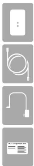
natural_image
Four grayscale product icons: a remote control unit, cable, plug-in plug, and a card reader interface (no text or symbols on icons)DIR-826L Wireless N600 Dual Band Gigabit Cloud Router
Ethernet Cable
Power Adapter
WI-FI Configuration Note
If any of the above items are missing, please contact your reseller.
Note: Using a power supply with a different voltage rating than the one included with the DIR-826L will cause damage and void the warranty for this product.
System Requirements
| Network.Requirements | An Ethernet-based Cable or DSL modemIEEE 802.11n or 802.11g wireless clients10/100/1000 Ethernet |
| Web-based.Configuration.Utility.Requirements | Computer.with.the.following:Windows®, Macintosh, or Linux-based operating systemAn installed Ethernet adapterBrowser.Requirements:Internet Explorer 7 or higherFirefox 3.5 or higherSafari 4 or higherChrome 8 or higherWindows*.Users:Make sure you have the latest version of Java installed. Visitwww.java.comto download the latest version. |
| mydlink.Requirements | iPhone/iPad/iPod Touch (iOS 3.0 or higher)Android device (1.6 or higher)Computer with the following browser requirements:Internet Explorer 7 or higherFirefox 3 or higherSafari 5 or higherChrome 5 or higheriPhone, iPad, and iPod touch are registered trademarks of Apple Inc. Android is a trademark of Google, Inc. |
Introduction
The D-Link Wireless N600 Dual Band Gigabit Cloud Router (DIR-826L) comes equipped with 4 Gigabit ports to provide speeds up to 10x faster than standard 10/100 ports. It also uses 802.11n technology with multiple intelligent antennas to maximize the speed and range of your wireless signal to significantly outperform 802.11g devices.
With the addition of Intelligent Quality of Service (QoS), data streams are separated which helps organize and prioritize your network traffic so your video streaming, gaming, and VoIP calls run smoother over both your wired and wireless network.
The D-Link Cloud Service will allow you to always have access to your home network no matter where you go. Now you can monitor and manage your home network right from your laptop, iPhone ^® , iPad ^® , or Android ^™ device. The cloud-enabled router can be configured to send an email to keep you informed anywhere, anytime when new devices are connecting to your network or unwanted access is detected. Monitor in real-time websites that are being visited with recent browser history displayed on the mydlink ^™ Lite app – which is great for parents.
The D-Link Cloud Service can detect and block unwelcomed guests who try to get into your wireless network and suspicious activities will be displayed right on your mydlink™ Lite app or browser.
Features
- Faster Wireless Networking - The DIR-826L provides up to 300Mbps* wireless connection with other 802.11n wireless clients. This capability allows users to participate in real-time activities online, such as video streaming, online gaming, and real-time audio. The performance of this 802.11n wireless router gives you the freedom of wireless networking at speeds 14x faster than 802.11g.
- Compatible with 802.11a/g Devices - The DIR-826L is still fully compatible with the IEEE 802.11g and 802.11a standards, so it can connect with existing 802.11g and 802.11a PCI, USB, and Cardbus adapters.
-
Advanced Firewall Features - The Web-based user interface displays a number of advanced network management features including:
-
Content Filtering - Easily applied content filtering based on MAC Address, URL, and/or Domain Name.
- Filter Scheduling - These filters can be scheduled to be active on certain days or for a duration of hours or minutes.
- Secure Multiple/Concurrent Sessions - The DIR-826L can pass through VPN sessions. It supports multiple and concurrent IPSec and PPTP sessions, so users behind the DIR-826L can securely access corporate networks.
- User-friendly Setup Wizard - Through its easy-to-use Web-based user interface, the DIR-826L lets you control what information is accessible to those on the wireless network, whether from the Internet or from your company's server. Configure your router to your specific settings within minutes.
* Maximum wireless signal rate derived from IEEE Standard 802.11a, 802.11g and 802.11n specifications. Actual data throughput will vary. Network conditions and environmental factors, including volume of network traffic, building materials and construction, and network overhead, lower actual data throughput rate. Environmental conditions will adversely affect wireless signal range.
Hardware Overview
Connections

text_image
1 2 3 4 5 6 USB WPS 1 2 3 4 INTERNET POWER| 1USB Port Connect a USB flash drive to share content throughout your network. | ||
| 2WPS Button Press to start the WPS process. The Internet LED will start to blink. | ||
| 3 | LAN Ports (1-4) | Connect 10/100/1000 Ethernet devices such as computers, switches, storage (NAS) devices and game consoles. |
| 4 | Internet Port | Using an Ethernet cable, connect your broadband modem to this port. |
| 5Power Button Press the power button to power on and off. | ||
| 6Power Receptor Receptor for the supplied power adapter. | ||
Hardware Overview LEDs

text_image
1 2| 1Power LED | A solid green light indicates a proper connection to the power supply. The light will blink green during the WPS process. The light will blink orange during boot up. |
| 2Internet LED | A solid light indicates connection on the Internet port. If the LED is orange, the connection is good but the router cannot connect to the Internet. |
Installation
This section will walk you through the installation process. Placement of the router is very important. Do not place the router in an enclosed area such as a closet, cabinet, or in the attic or garage.
Before you Begin
- Please configure the router with the computer that was last connected directly to your modem.
- You can only use the Ethernet port on your modem. If you were using the USB connection before using the router, then you must turn off your modem, disconnect the USB cable and connect an Ethernet cable to the Internet port on the router, and then turn the modem back on. In some cases, you may need to call your ISP to change connection types (USB to Ethernet).
- If you have DSL and are connecting via PPPoE, make sure you disable or uninstall any PPPoE software such as WinPoet, Broadjump, or Enternet 300 from your computer or you will not be able to connect to the Internet.
Wireless Installation Considerations
The D-Link wireless router lets you access your network using a wireless connection from virtually anywhere within the operating range of your wireless network. Keep in mind, however, that the number, thickness and location of walls, ceilings, or other objects that the wireless signals must pass through, may limit the range. Typical ranges vary depending on the types of materials and background RF (radio frequency) noise in your home or business. The key to maximizing wireless range is to follow these basic guidelines:
- Keep the number of walls and ceilings between the D-Link router and other network devices to a minimum - each wall or ceiling can reduce your adapter's range from 3-90 feet (1-30 meters.) Position your devices so that the number of walls or ceilings is minimized.
- Be aware of the direct line between network devices. A wall that is 1.5 feet thick (.5 meters), at a 45-degree angle appears to be almost 3 feet (1 meter) thick. At a 2-degree angle it looks over 42 feet (14 meters) thick! Position devices so that the signal will travel straight through a wall or ceiling (instead of at an angle) for better reception.
- Building Materials make a difference. A solid metal door or aluminum studs may have a negative effect on range. Try to position access points, wireless routers, and computers so that the signal passes through drywall or open doorways. Materials and objects such as glass, steel, metal, walls with insulation, water (fish tanks), mirrors, file cabinets, brick, and concrete will degrade your wireless signal.
- Keep your product away (at least 3-6 feet or 1-2 meters) from electrical devices or appliances that generate RF noise.
- If you are using 2.4GHz cordless phones or X-10 (wireless products such as ceiling fans, lights, and home security systems), your wireless connection may degrade dramatically or drop completely. Make sure your 2.4GHz phone base is as far away from your wireless devices as possible. The base transmits a signal even if the phone in not in use.
Manual Setup
- Turn off and unplug your cable or DSL broadband modem. This is required.
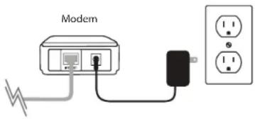
text_image
Modem- Position your router close to your modem and a computer. Place the router in an open area of your intended work area for better wireless coverage.
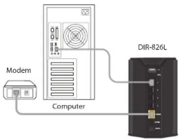
- Unplug the Ethernet cable from your modem (or existing router if upgrading) that is connected to your computer. Plug it into the LAN port labeled 1 on the back of your router. The router is now connected to your computer.

text_image
DIR-826LComputer
- Plug one end of the included blue Ethernet cable that came with your router into the yellow port labeled INTERNET on the back of the router. Plug the other end of this cable into the Ethernet port on your modem.
text_image
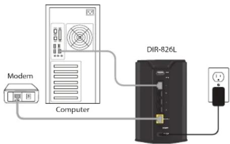
Modem Computer DIR-826L- Reconnect the power adapter to your cable or DSL broadband modem and wait for two minutes.
- Connect the supplied power adapter into the power port on the back of the router and then plug it into a power outlet or surge protector. Press the power button and verify that the power LED is lit. Allow 1 minute for the router to boot up.
flowchart
graph TD
    A["Modem"] --> B["Computer"]
    B --> C["DIR-826L"]
    C --> D["Power Supply"]
- If you are connecting to a Broadband service that uses a dynamic connection (not PPPoE), you may be online already. Try opening a web browser and enter a web site. If you connect, you are finished with your Internet setup. Please skip to page 13 to configure your router and use the manual setup procedure to configure your network and wireless settings. If you did not connect to the Internet, use the D-Link Setup Wizard (refer to page 14).
Connect to an Existing Router
Note: It is strongly recommended to replace your existing router with the DIR-826L instead of using both. If your modem is a combo router, you may want to contact your ISP or manufacturer's user guide to put the router into Bridge mode, which will 'turn off' the router (NAT) functions.
If you are connecting the DIR-826L router to an existing router to use as a wireless access point and/or switch, you will have to do the following to the DIR-826L before connecting it to your network:
- Disable UPnP ^TM
- Disable DHCP
- Change the LAN IP address to an available address on your network. The LAN ports on the router cannot accept a DHCP address from your other router.
To connect to another router, please follow the steps below:
- Plug the power into the router. Connect one of your computers to the router (LAN port) using an Ethernet cable. Make sure your IP address on the computer is 192.168.0.xxx (where xxx is between 2 and 254). Please see the Networking Basics section for more information. If you need to change the settings, write down your existing settings before making any changes. In most cases, your computer should be set to receive an IP address automatically in which case you will not have to do anything to your computer.
- Open a web browser, enter http://192.168.0.1 and press Enter. When the login window appears, set the user name to Admin and leave the password box empty. Click Log In to continue.
- Click on Advanced and then click Advanced Network. Uncheck the Enable UPnP checkbox. Click Save Settings to continue.
- Click Setup and then click Network Settings. Uncheck the Enable DHCP Server checkbox. Click Save Settings to continue.
Section 2 - Installation
- Under Router Settings, enter an available IP address and the subnet mask of your network. Click Save.Settings to save your settings. Use this new IP address to access the configuration utility of the router in the future. Close the browser and change your computer's IP settings back to the original values as in Step 1.
- Disconnect the Ethernet cable from the router and reconnect your computer to your network.
- Connect an Ethernet cable in one of the LAN ports of the router and connect it to your other router. Do not plug anything into the Internet (WAN) port of the D-Link router.
- You may now use the other 3 LAN ports to connect other Ethernet devices and computers. To configure your wireless network, open a web browser and enter the IP address you assigned to the router. Refer to the Configuration and Wireless Security sections for more information on setting up your wireless network.
Configuration
There are several different ways you can configure your router to connect to the Internet and connect to your clients:
- Quick.Setup.Wizard - This wizard will launch when you log into the router for the first time. Refer to page 14.
- QRS.Mobile.App.- Use your iPhone, iPad, or iPod Touch to configure your router. Refer to page 21.
- SharePort.Mobile- This will allow you to access files from a USB thumb drive that is plugged into your router. Refer to page 22.
- Web.Based.Configuration.Utility-To access the configuration utility, open a web-browser such as Internet Explorer and enter the IP address of the router (http://192.168.0.1). Refer to page 26.
Quick Setup Wizard
If this is your first time installing the router, open your web browser. You will automatically be directed to the Wizard Setup Screen.
If you have already configured your settings and you would like to access the configuration utility, please refer to page 26.
If this is your first time logging into the router, this wizard will start automatically.
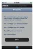
This wizard is designed to guide you through a step-by-step process to configure your new D-Link router and connect to the Internet.
Click Next to continue.

text_image
D-Link - Home & Home Office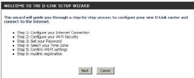
text_image
WELCOME TO THE D-LINK SETUP WIZARD This wizard will guide you through a step-by-step process to configure your new D-Link router and connect to the Internet. • Step 1: Configure your Internet Connection • Step 2: Configure your Wi-Fi Security • Step 3: Set your Password • Step 4: Select your Time Zone • Step 5: Confirm Wi-Fi settings • Step 6: mydink registration Next CancelPlease wait while your router detects your internet connection type. If the router detects your Internet connection, you may need to enter your ISP information such as username and password.

text_image
STEP 1: CONFIGURE YOUR INTERNET CONNECTION Router is detecting your Internet connection type, please wait ... New Next CancelSection 3 - Configuration
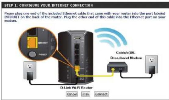
If the router does not detect a valid Ethernet connection from the Internet port, this screen will appear. Connect your broadband modem to the Internet port and then click Try.Again.
text_image
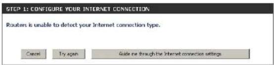
STEP 1: CONFIGURE YOUR INTERNET CONNECTION Please plug one end of the included Ethernet cable that came with your router into the port labeled INTERNET on the back of the router. Plug the other end of this cable into the Ethernet port on your modem. D-Link Wi-Fi Router Cancel Prev Connect Cable/xDSL Broadband ModemIf the router detects an Ethernet connection but does not detect the type of Internet connection you have, this screen will appear. Click Guide.me. through.the.Internet.Connection.Settings to display a list of connection types to choose from.
text_image
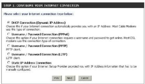
STEP 1: CONFIGURE YOUR INTERNET CONNECTION Routers is unable to detect your Internet connection type. Cancel Try again Guide me through the Internet connection settingsSelect your Internet connection type and click Next to continue.
text_image
STEP 1: CONFIGURE YOUR INTERNET CONNECTION Please select your Internet connection type below: ○ DHCP Connection (Dynamic IP Address) Choose this if your Internet connection automatically provides you with an IP Address. Most Cable Modems use this type of connection. ○ Username / Password Connection (PPPoE) Choose this option if your Internet connection requires a username and password to get online. Most DSL modems use this connection type of connection. ○ Username / Password Connection (PPTP) PPTP client. ○ Username / Password Connection (L2TP) L2TP client. ○ Static IP Address Connection Choose this option if your Internet Setup Provider provided you with IP Address information that has to be manually configured. Prev Next CancelSection 3 - Configuration
If the router detected or you selected PPPoE, enter your PPPoE username and password and click Next to continue.
Note: Make sure to remove your PPPoE software from your computer. The software is no longer needed and will not work through a router.
If the router detected or you selected PPTP, enter your PPTP username, password, and other information supplied by your ISP. Click Next to continue.
If the router detected or you selected L2TP, enter your L2TP username, password, and other information supplied by your ISP. Click Next to continue.

text_image
SET USERNAME AND PASSWORD CONNECTION (PPPOE) To set up this connection you will need to have a username and Password from your Internet Service Provider. If you do not have this information, please contact your ISP. User Name : Password : Prev Next Cancel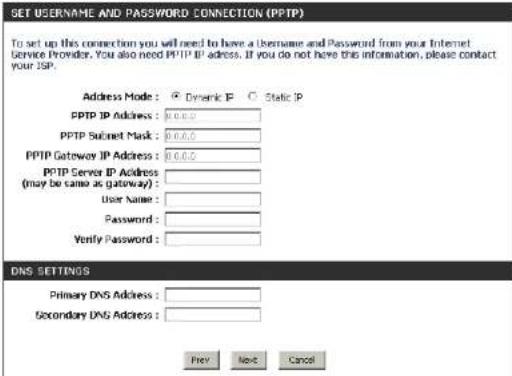
text_image
SET USERNAME AND PASSWORD CONNECTION (PPTP) To set up this connection you will need to have a username and Password from your Internet Service Provider. You also need PPTP IP address. If you do not have this information, please contact your JSP. Address Mode: Dynamic IP Static IP PPTP IP Address: 0.0.0.0 PPTP Subnet Mask: 0.0.0.0 PPTP Gateway IP Address: 0.0.0.0 PPTP Server IP Address (may be came as gateway): User Name: Password: Verify Password: DNS SETTINGS Primary DNS Address: Secondary DNS Address: Prev Next Cancel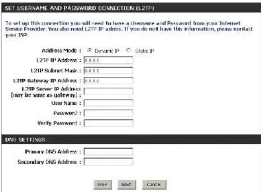
text_image
GET USERNAME AND PASSWORD CONNECTION (L2TP) To set up this connection you will need to have a Username and Password from your Internet Service Provider. You also need L2TP IP address. If you do not have this information, please contact your ISP. Address Mode: Dynamic IP Static IP L2TP IP Address: 0.0.0.0 L2TP Subnet Mask: 0.0.0.0 L2TP Gateway IP Address: 0.0.0.0 L2TP Server IP Address (may be same as gateway): User Name: Password: Verify Password: DNS SETTINGS Primary DNS Address: Secondary DNS Address: Prey Next CancelSection 3 - Configuration
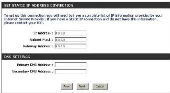
If the router detected or you selected Static, enter the IP and DNS settings supplied by your ISP. Click Next to continue.
For both the 2.4GHz and 5GHz segments, create a Wi-Fi network name (SSID) using up to 32 characters.
Create a Wi-Fi password (between 8-63 characters). Your wireless clients will need to have this passphrase or key entered to be able to connect to your wireless network.
Click Next to continue.
In order to secure your router, please enter a new password. Check the Enable Graphical Authentication box to enable CAPTCHA authentication for added security. Click Next to continue.
text_image
SET STATIC IP ADDRESS CONNECTION To set up this connection you will need to have a complete list of IP information provided by your Internet Service Provider. If you have a Static IP connection and do not have this information, please contact your ISP. IP Address: 0.0.0.0 Subnet Mask: 0.0.0.0 Gateway Address: 0.0.0.0 DNS SETTINGS Primary DNS Address: Secondary DNS Address: Prev Next Cancel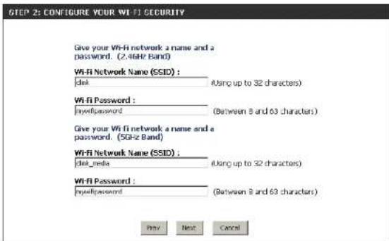
text_image
STEP 2: CONFIGURE YOUR WIFI SECURITY Give your WIFI network a name and a password. (2.4GHz Band) WIFI Network Name (SSID) : del (Using up to 32 characters) WIFI Password : hydipassword (Between 8 and 63 characters) Give your WIFI network a name and a password. (5GHz Band) WIFI Network Name (SSID) : del_media (Using up to 32 characters) WIFI Password : hydipassword (Between 8 and 63 characters) Prev Next Cancel
text_image
STEP 3: SET YOUR PASSWORD By default, your new D-Link Router does not have a password configured for administrator access to the Web-based configuration pages. To secure your new networking device, please set and verify a password below, and enabling CRO IOHIA Graphical Authentication provides added security protection to prevent unauthorized online users and hacker software from accessing your network settings. Password: Verify Password: Enable Graphical Authentication: Prev Next CancelSection 3 - Configuration
Select your time zone from the drop-down menu and click Next to continue.
The Setup Complete window will display your Wi-Fi settings. Click Save. and. Connect to continue.
If you want to create a bookmark to the router, click OK. Click Cancel if you do not want to create a bookmark.
If you clicked Yes, a window may appear (depending on what web browser you are using) to create a bookmark.

text_image
STEP 4: SELECT YOUR TIME ZONE Select the appropriate time zone for your location. This information is required to configure the time-based options for the router. (GNT-08:00 Pacific Time (US/Canada), Fijiana Pre Next Cancel
text_image
STEP 5: CONFIRM WIFI SETTINGS Below is a detailed summary of your Wi-Fi security settings. Please print this page out, or write the information on a piece of paper, so you can configure the correct settings on your Wi-Fi devices. Wi-Fi Network Name (SSID) 2.4GHz Band: dink Wi-Fi Password: mywif/password Wi-Fi Network Name (SSID) 5GHz Band: dink media Wi-Fi Password: mywif/password The Setup Wizard has completed. Click the save button to save your settings and reboot the router.
text_image
Microsoft Internet Explorer Do you want to bookmark "D-Link Router Web Management" OK Cancel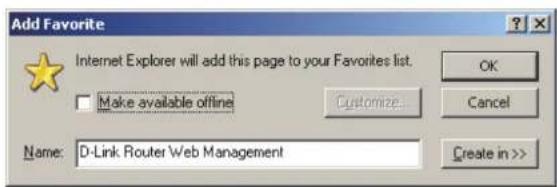
text_image
Add Favorite Internet Explorer will add this page to your Favorites list. Make available offline Customize... Name: D-Link Router Web Management OK Cancel Create in >>Section 3 - Configuration
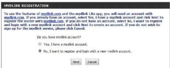
To use the mydlink service (mydlink.com or the mydlink Lite app), you must have an account. Select if you do have a mydlink account or if you need to create one. Click Next to continue.
If you do not want to register at this time, click Cancel.
If you clicked Yes, enter your mydlink account name (email address) and password. Click Login to register your router.
If you clicked No, fill out the requested information and click Next to create your mydlink account.
Once your account information is entered, click Login.
text_image
Mydlink REGISTRATION To use the features of mydlink.com and the mydlink Lite app, you will need an account with mydlink.com. If you already have an account, select Yes, I have a mydlink account and click Next to register the router with mydlink.com. If you do not have an account, select No, I want to register and login with a new mydlink account and click Next to create an account. If you do not wish to sign up for the mydlink service, please click Cancel. Do you have mydlink account? Yes, I have a mydlink account. No, I want to register and login with a new mydlink account. Next Cancel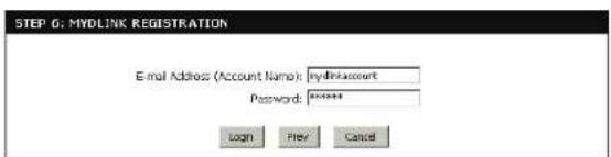
text_image
STEP 6: MYDLINK REGISTRATION E-mail Address (Account Name): mydlinkaccount Password: Login Prev Cancel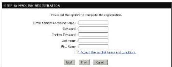
text_image
STEP 6: MYDLINK REGISTRATION Please full the options to complete the registration. Email Address (Account Name) : Password : Confirm Password : Last name : First Name : □ Accept the hyperlink terms and conditions. Next Prev Cancel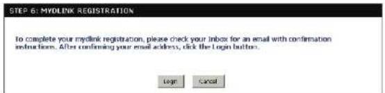
text_image
STEP 6: MYOLINK REGISTRATION To complete your myolink registration, please check your inbox for an email with confirmation instructions. After confirming your email address, click the login button. Login CancelSection 3 - Configuration
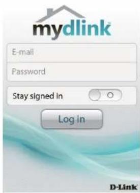
The mydlink App will allow you to receive notices, browse network users, and configure your router from an iPhone/iPad/iPod Touch (iOS 3.0 or higher), Android device (1.6 or higher).
To download the "mydlink lite" app, visit the Apple Store, Android Market or http://mydlink.com/Lite.
text_image
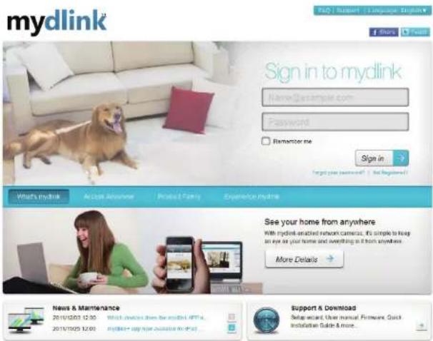
mydlink E-mail Password Stay signed in Log in D-LinkPC and Mac users can use the mydlink portal at http://mydlink.com.
text_image
mydlink Sign in to mydlink Name: sample.com Password Remancer me Sign in Target your website? | Not registered! What's mydlink Access Anyone Product Family Experience Mydlink See your home from anywhere With mydlink enacted network cameras, it's simple to help on eye at your home and everything it from anywhere. More Details News & Maintenance 2010/12/07 12:00 2010/12/25 12:00 Mydlink® copyright database to what Support & Download Setup restart, User manual. Firmware, Quick Installation Guide & more.QRS Mobile App
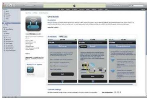
D-Link offers an app for your iPad, iPod Touch, or iPhone (iOS 4.3 or higher) to install and configure your router.
Step.1
From your iPad, Touch, or iPhone, go to the iTunes Store and search for 'D-Link'. Select QRS.Mobile and then download it.
You may also scan this code to download.

text_image
QPSO Module Description Results and results from the following functions: QPSO Module is a new version of the QPSO Module. It is also a version of the QPSO Module. It is also a version of the QPSO Module. It is also a version of the QPSO Module. It is also a version of the QPSO Module. It is also a version of the QPSO Module. It is also a version of the QPSO Module. It is also a version of the QPSO Module. It is also a version of the QPSO Module. It is also a version of the 2016 QPSO Module (2017) QPSO Module Parameters QPSO Module Database Settings Database name: qpso.com, database name: qpso.com, database type: database, database size: 500x, 500x, 500x, 500x, 500x, 500x, 500x, 500x, 500x, 500x, 500x, 500x, 500x, 500x, 500x, 500x, 500x, 50 QPSO Module Database name: qpso.com, database name: qpso.com, database size: 500x, 500x, 500x, 500x, 500x, 500x, 500x, 500x, 500x, 500x, 500x, 500x, 50 QPSO Module Database name: qpso.com, database name: qpso.com, database size/size: 500x, 500x, 500x, 500x, 500x, 500x, 500x, 500x, 500x, 50 QPSO Module Database name: qpso.com, database name: qpso.com, database size/size: 500x, 500x, 501x, 501x, 501x, 501x, 501x, 501x, 501x, 501x, 501x, 501x, 50 QPSO Module Database name: qpso.com, database name: qpso.com, database size/size: 518x, 518x, 518x, 518x, 518x, 518x, 518x, 518x, 518x, 518x, 518x, 518x, 518x QPSO Module Database name: qpso.com, database name: qpso.com, database size/size: 493x, 493x, 493x, 493x, 493x, 493x, 493x, 493x, 493x, 493x, 493x, 493x QPSO Module Database name: qpso.com, database name: qpso.com, database size/size: 493x, 493x, 493x, 493x, 493x, 493x, 493x, 493x, 493x, 493x QPSO Module Database name: qpso.com, database name: qpso.com, database size/size: 493x, 493x, 518x, 493x, 493x, 493x, 493x, 493x, 493x, 493x QPSO Module Database name: qpso.com, database name: qpso.com, database size/size: 493x, 493x, 493x, 493x, 493x-26666666666666666666666666666666666666666666666666666666666666666666666666666666666666666666666666666Step.2
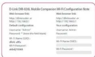
Once your app is installed, you may now configure your router. Connect to the router wirelessly by going to your wireless utility on your device. Scan for the Wi-Fi name (SSID) as listed on the supplied info card. Select and then enter your Wi-Fi password.
text_image
D-Link DR-826L Mobile Companion Wi-Fi Configuration Note Web browser link: http://ellmroder or http://192.168.0.1 Default configuration Username "Admin" Password: " (have the field block) Wi-Fi Name (SDD): aAff, offa Wi-Fi Password: abdfj13348 Web browser link: http://ellmroder or http://192.168.0.1 Your configuration Username Admin Password: Wi-Fi Name (SDD): Wi-Fi Password: abdfj13348 Wi-Fi Password:Step.3
Once you connect to the router, launch the QRS mobile app and it will guide you through the installation of your router.
SharePort Mobile App
The SharePort Mobile app will allow you to access files from a USB thumb drive that is plugged into your router. You must enable file sharing from the Setup > Storage page (refer to page 53) for this app to work properly.
-
Insert your USB flash drive into DIR-826L.
-
Scan the bar code to download the SharePort Mobile APP from the app store to your iPhone or iPad.
-
From your iOS mobile device, click Settings.


text_image
SettingsSection 3 - Configuration
- Click Wi-Fi, select the Wi-Fi Network Name (SSID) that you created in the setup and then enter your Wi-Fi password.

text_image
Settings Bluetooth Networks Wi-Fi Windows 9.0000 736-0148 Chocolate Data: WiFi, AT348 AVOC 800-800L 800-800R 055-636M_1 570/570Mbps Fastly Wt Strawberry Thread gamma- Once connected, click on the SharePort Mobile icon.

text_image
3:40 PM SharePort- The following screen will appear.

text_image
< Files >Section 3 - Configuration
-
Click on Settings icon located on the right top corner of the screen. Click Edit to enter your User Name and Password. Once you finish, click Done to continue.
-
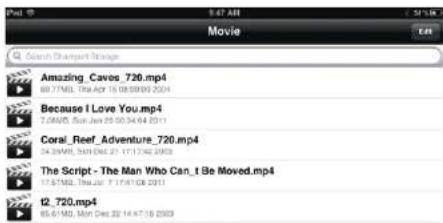
For the Movie section, click the movie icon to play your movie from your USB flash drive.
-
For the Music section, click the music icon to play your music from your USB flash drive.

text_image
File
text_image
Movie Search Snapshot Stringer Amazing Cavos_720.mp4 88.71MB, Tue Apr 15 08:09:00 2014 Because I Love You.mp4 7.0MWD, Sun Jun 25 00:34:64 2011 Coral_Reef_Adventure_720.mp4 14.3MWD, Sat Wed 21 17:12:02 2009 The Script - The Man Who Can_I Be Moved.mp4 17.57MB, Thu Dec 27 17:11:08 2011 t2_720.mp4 85.61MB, Mon Wed 22 14:47:16 2003

text_image
Music Search Chancorp Storage 101-bon_jovi_-_livin_on_a_prayer-ysp.mp3 6.7MB, Fri Oct 29 23:33:12 2015 102-bon_jovi_-_you_give_love_a_bad_name-ysp.mp3 6.4MB, Fri Oct 29 23:33:12 2015 103-bon_jovi_-_its_my_life-ysp.mp3 5.4MB, Fri Oct 29 23:30:10 2015 104-bon_jovi_-_have_a_nice_day-ysp.mp3 6.5MB, Fri Oct 29 23:30:14 2015 105-bon_jovi_-_wanted_dead_or_alive-ysp.mp3 8.11MB, Fri Oct 29 23:30:22 2015Section 3 - Configuration
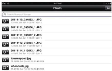
- For the Photo section, click the Photo icon to view your photos from your USB flash drive.

text_image
Photo Search Shareout Storage 20111110_234852_1.JPG 0.21MB, Sat Jan 1 09:30:10 2011 2011111_095006_1.JPG 1.42MB, Sat Jan 1 09:22:12 2011 2011111_095007_2.JPG 1.08MB, Sat Jan 1 09:22:16 2011 20111112_215934_1.JPG 1.25MB, Sat Jan 1 09:43:8 2011 20111114_113643_1.JPG 0.03MB, Sat Jan 1 01:30:32 2011 tonemapped.jpg 16.24KB, Sun Nov 22 14:24:42 2009 whoooosh.jpg 83.42KB, Sun Nov 22 14:24:42 2009- For the Files section, click on the Files icon to view your files from your USB flash drive.


text_image
File Ken2011-12.docx 36-45.5, Thu: 8:12-2012- For the Folder section, click the folder icon to view your folders from your USB flash drive.


text_image
File 7 9:48 AM 12:15 E: Folder Search Transport Storage DIR-505 Files found.000Web-based Configuration Utility
To access the configuration utility, open a web-browser such as Internet Explorer and enter the IP address of the router (http://192.168.0.1).
Windows and Mac users may also connect by typing http://dlinkrouter in the address bar.
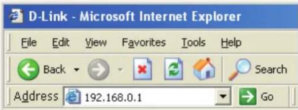
text_image
D-Link - Microsoft Internet Explorer File Edit View Favorites Tools Help Back Search Address 192.168.0.1 GoSelect Admin from the drop-down menu and then enter your password. Leave the password blank by default.

text_image
LOGIN Log in to the router User Name : Admin Password : LoginInternet Connection Setup
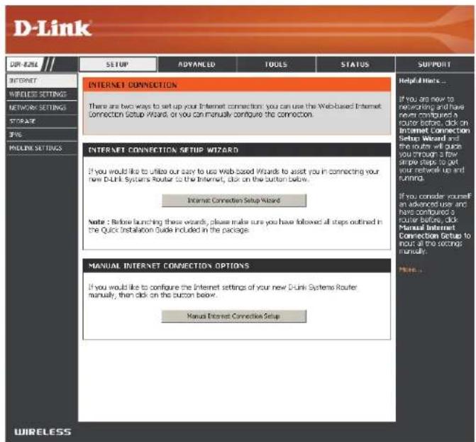
Click Manual.Internet.Connection.Setup to configure your connection manually and continue to the next page.
If you want to configure your router to connect to the Internet using the wizard, click Internet.Connection.Setup.Wizard. You will be directed to the Quick Setup Wizard. Please refer to page 14.
text_image
D-Link OR #ZILE INTERNET WIRELESS SETTINGS NETWORK SETTINGS STORAGE IP# PAYOUTS SETTINGS SETUP ADVANCED TOOLS STATUS INTERNET CONNECTION There are two ways to set up your Internet connection: you can use the Web-based Internet Connection Setup Wizard, or you can manually configure the connection. INTERNET CONNECTION SETUP WIZARD If you would like to utilize our way to use Web based Wizard to assist you in connecting your new D-Link Systems Router to the Internet, click on the button below. Internet Connection Setup Wizard Note : Before launching these wizards, please make sure you have followed all steps outlined in the Quick Installation Guide Included in the package. MANUAL INTERNET CONNECTION OPTIONS If you would like to configure the Internet settings of your new D-Link Systems Router manually, then click on the button below. Manual Internet Connection Setup Helpful Hinks... If you are now to networking and have never configured a router before, click on Internet Connection Setup Wizard and the route will quick you enough a few simple steps to get your network up and running. If you consider yourself an advanced user and have configured a router before, click Manual Internet Connection Setup to include all the seconds manually. NOTE...Manual Internet Setup Static (assigned by ISP)
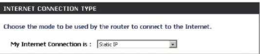
Select Static IP Address if all the Internet port's IP information is provided to you by your ISP. You will need to enter in the IP address, subnet mask, gateway address, and DNS address(es) provided to you by your ISP. Each IP address entered in the fields must be in the appropriate IP form, which are four octets separated by a dot (x.x.x.x). The Router will not accept the IP address if it is not in this format.
My Internet Connection: Select Static.IP to manually enter the IP settings supplied by your ISP.
Enable Advanced DNS Service: Advanced Domain Name System (DNS) services enhances your Internet performance by getting you the information and web pages you are looking for faster and more reliably. In addition, it improves your overall Internet experience by correcting many common typo mistakes automatically, taking you where you intended to go and saving you valuable time.
Disclaimer: D-Link makes no warranty as to the availability, reliability, functionality and operation of the Advanced DNS service or its features.
Enable True Gigabit Check to enable true Gigabit routing. This will increase the Routing Connectivity: through-put of the WAN-LAN connectivity of the router.
IP Address: Enter the IP address assigned by your ISP.
Subnet Mask: Enter the Subnet Mask assigned by your ISP.
Default Gateway: Enter the Gateway assigned by your ISP.
DNS Servers: The DNS server information will be supplied by your ISP (Internet Service Provider.)
text_image
INTERNET CONNECTION TYPE Choose the mode to be used by the router to connect to the Internet. My Internet Connection is : Static IP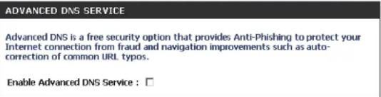
text_image
ADVANCED DNS SERVICE Advanced DNS is a free security option that provides Anti-Phishing to protect your Internet connection from fraud and navigation improvements such as auto-correction of common URL typos. Enable Advanced DNS Service : □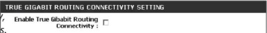

text_image
STATIC IP ADDRESS INTERNET CONNECTION TYPE Enter the static address information provided by your Internet Service Provider (ISP). IP Address : 0.0.0.0 Subnet Mask : 0.0.0.0 Default Gateway : 0.0.0.0 Primary DNS Server : 0.0.0.0 Secondary DNS Server : 0.0.0.0 MTU : 1500 (bytes) MTU default = 1500 MAC Address : 06:18:E7:95:68:9F Copy Your PC's MAC AddressMTU: Maximum Transmission Unit - you may need to change the MTU for optimal performance with your specific ISP. 1500 is the default MTU.
Section 3 - Configuration
MAC Address: The default MAC Address is set to the Internet port's physical interface MAC address on the Broadband Router. It is not recommended that you change the default MAC address unless required by your ISP. You can use the Copy.Your.PC's.MAC.Address button to replace the Internet port's MAC address with the MAC address of your Ethernet card.
Dynamic (Cable)
My Internet Select Dynamic.IP.(DHCP) to obtain IP Address information
Connection: automatically from your ISP. Select this option if your ISP does not give you any IP numbers to use. This option is commonly used for cable modem services.
Enable Advanced Advanced Domain Name System (DNS) services enhances your Internet
DNS Service: performance by getting you the information and web pages you are looking for faster and more reliably. In addition, it improves your overall Internet experience by correcting many common typo mistakes automatically, taking you where you intended to go and saving you valuable time.
Disclaimer: D-Link makes no warranty as to the availability, reliability, functionality and operation of the Advanced DNS service or its features.
Enable True Gigabit Check to enable true Gigabit routing. This will increase the through-put Routing Connectivity: of the WAN-LAN connectivity of the router.
Host Name: The Host Name is optional but may be required by some ISPs. Leave blank if you are not sure.
Use Unicasting: Check the box if you are having problems obtaining an IP address from your ISP.

text_image
INTERNET CONNECTION TYPE Choose the mode to be used by the router to connect to the Internet. My Internet Connection is: Dynamic IP (DHCP) ADVANCED DNS SERVICE Advanced DNS is a free security option that provides Anti-Phishing to protect your Internet connection from fraud and navigation improvements such as auto-correction of common URL typos. Enable Advanced DNS Service: TRUE GIGABIT ROUTING CONNECTIVITY SETTING Enable True Gibabit Routing Connectivity: DYNAMIC IP (DHCP) INTERNET CONNECTION TYPE Use this Internet connection type if your Internet Service Provider (ISP) didn't provide you with IP Address information and/or a username and password. Host Name: DIR-826L Use Unicasting: ✓ (compatibility for some DHCP Servers) Primary DNS Server: 0.0.0.0 Secondary DNS Server: 0.0.0.0 MTU: 1500 (bytes)MTU default =1500 MAC Address: 00:18:E7:95:68:SF Copy Your PCS MAC AddressPrimary/Secondary Enter the Primary and secondary DNS server IP addresses assigned by your ISP. These addresses are usually obtained automatically DNS Server: from your ISP. Leave at 0.0.0.0 if you did not specifically receive these from your ISP.
MTU: Maximum Transmission Unit - you may need to change the MTU for optimal performance with your specific ISP. 1500 is the default MTU.
MAC Address: The default MAC Address is set to the Internet port's physical interface MAC address on the Broadband Router. It is not recommended that you change the default MAC address unless required by your ISP. You can use the Copy.Your.PC's.MAC.Address button to replace the Internet port's MAC address with the MAC address of your Ethernet card.
Internet Setup
PPPoE (DSL)
Choose PPPoE (Point to Point Protocol over Ethernet) if your ISP uses a PPPoE connection. Your ISP will provide you with a username and password. This option is typically used for DSL services. Make sure to remove your PPPoE software from your computer. The software is no longer needed and will not work through a router.
My Internet Select PPPoE.(Username/Password) from the drop-down menu.
Connection:
Enable Advanced Domain Name System (DNS) services enhances your Internet Advanced DNS performance by getting you the information and web pages you are looking
Service: for faster and more reliably. In addition, it improves your overall Internet experience by correcting many common typo mistakes automatically, taking you where you intended to go and saving you valuable time.
Disclaimer: D-Link makes no warranty as to the availability, reliability, function and operation of the Advanced DNS service or its features.
Enable True Check to enable true Gigabit routing. This will increase the through-put of Gigabit Routing the WAN-LAN connectivity of the router.
Connectivity:
Address Mode: Select Static.IP if your ISP assigned you the IP address, subnet mask, gateway, and DNS server addresses. In most cases, select Dynamic.
IP Address: Enter the IP address (Static PPPoE only).
User Name: Enter your PPPoE user name.
Password: Enter your PPPoE password and then retype the password in the next box.
Service Name: Enter the ISP Service Name (optional).
Reconnect Select either Always-on, On-Demand, or Manual. Mode:
INTERNET CONNECTION TYPE
Choose the mode to be used by the router to connect to the Internet.
My Internet Connection is : PPPoE (Username / Password)
ADVANCED DNS SERVICE
Advanced DNS is a free security option that provides Anti-Phishing to protect your Internet connection from fraud and navigation improvements such as auto-correction of common URL typos.
Enable Advanced DNS Service : □

TRUE GIGABIT ROUTING CONNECTIVITY SETTING
Enable True Gibabit Routing Connectivity :
PPPOE INTERNET CONNECTION TYPE
Enter the information provided by your Internet Service Provider (ISP).
text_image
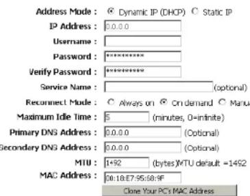
Address Mode: © Dynamic IP (DHCP) © Static IP IP Address: 0.0.0.0 Username: Password: ********** Verify Password: ********** Service Name: (optional) Reconnect Mode: ○ Always on © On demand ○ Manual Maximum Idle Time: 5 (minutes, 0-infinite) Primary DNS Address: 0.0.0.0 (Optional) Secondary DNS Address: 0.0.0.0 (Optional) MTU: 1+92 (bytes)MTU default =1492 MAC Address: 30:18:E7:95:60:9F Clone Your PC's MAC AddressSection 3 - Configuration
Maximum Enter a maximum idle time during which the Internet connection is maintained during inactivity. To disable this feature, enable Idle Time: Auto-reconnect.
DNS Enter the Primary and Secondary DNS Server Addresses (Static PPPoE only).
Addresses:
MTU: Maximum Transmission Unit - you may need to change the MTU for optimal performance with your specific ISP. 1492 is the default MTU.
MAC Address: The default MAC Address is set to the Internet port's physical interface MAC address on the Broadband Router. It is not recommended that you change the default MAC address unless required by your ISP. You can use the Copy.Your.PC's.MAC.Address button to replace the Internet port's MAC address with the MAC address of your Ethernet card.
Internet Setup PPTP
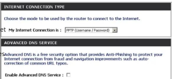
Choose PPTP (Point-to-Point-Tunneling Protocol) if your ISP uses a PPTP connection. Your ISP will provide you with a username and password. This option is typically used for DSL services.
My Internet Select PPTP.(Username/Password) from the drop-down menu. Connection:
Enable Advanced Domain Name System (DNS) services enhances your Internet performance by getting you the information and web pages you are looking for faster and more reliably. In addition, it improves your overall Internet experience by correcting many common typo mistake automatically, taking you where you intended to go and saving you valuable time.
Disclaimer: D-Link makes no warranty as to the availability, reliability, functionality and operation of the Advanced DNS service or its features.
Enable True Check to enable true Gigabit routing. This will increase the throughput Gigabit Routing of the WAN-LAN connectivity of the router. Connectivity:
Address Mode: Select Static if your ISP assigned you the IP address, subnet mask, gateway, and DNS server addresses. In most cases, select Dynamic.
PPTP IP Address: Enter the IP address (Static PPTP only).
PPTP Subnet Enter the Primary and Secondary DNS Server Addresses (Static PPTP Mask: only).
PPTP Gateway: Enter the Gateway IP Address provided by your ISP.
PPTP Server IP: Enter the Server IP provided by your ISP (optional).
text_image
INTERNET CONNECTION TYPE Choose the mode to be used by the router to connect to the Internet. et My Internet Connection is : PPTP (Username / Password) ADVANCED DNS SERVICE SAdvanced DNS is a free security option that provides Anti-Phishing to protect your Internet connection from fraud and navigation improvements such as auto-correction of common URL typos. Enable Advanced DNS Service : □
text_image
PPTP Enter the information provided by your Internet Service Provider (ISP). Address Mode: Dynamic IP (DHCP) Static IP PPTP IP Address: 0.0.0.0 PPTP Subnet Mask: 0.0.0.0 PPTP Gateway IP Address: 0.0.0.0 PPTP Server IP Address: Username: Password: ********** Verify Password: ********** Reconnect Mode: Always on On demand Manual Maximum Idle Time: 5 (minutes, 0=infinite) Primary DNS Address: 0.0.0.0 Secondary DNS Address: 0.0.0.0 MTU: 1400 (bytes)MTU default = 1400 MAC Address: 00:18:E7:95:68:9F Clone Your PC's MAC AddressSection 3 - Configuration
Username: Enter your PPTP username.
Password: Enter your PPTP password and then retype the password in the next box.
Reconnect Select either Always-on, On-Demand, or Manual. Mode:
Maximum Idle Enter a maximum idle time during which the Internet connection is maintained during inactivity. To disable this feature, enable Time: Auto-reconnect.
DNS Servers: The DNS server information will be supplied by your ISP (Internet Service Provider.)
MTU: Maximum Transmission Unit - you may need to change the MTU for optimal performance with your specific ISP. 1400 is the default MTU.
MAC Address: The default MAC Address is set to the Internet port's physical interface MAC address on the Broadband Router. It is not recommended that you change the default MAC address unless required by your ISP. You can use the Clone.Your.PC's.MAC.Address button to replace the Internet port's MAC address with the MAC address of your Ethernet card.
Internet Setup
L2TP
Choose L2TP (Layer 2 Tunneling Protocol) if your ISP uses a L2TP connection. Your ISP will provide you with a username and password. This option is typically used for DSL services.
My Internet Select L2TP.(Username/Password) from the drop-down menu. Connection:
Enable Advanced Domain Name System (DNS) services enhances your Advanced DNS Internet performance by getting you the information and web Service: pages you are looking for faster and more reliably. In addition, it improves your overall Internet experience by correcting many common typo mistakes automatically, taking you where you intended to go and saving you valuable time.
Disclaimer: D-Link makes no warranty as to the availability, reliability, functionality and operation of the Advanced DNS service or its features.
Enable True Check to enable true Gigabit routing. This will increase the Gigabit Routing through-put of the WAN-LAN connectivity of the router. Connectivity:
Address Mode: Select Static if your ISP assigned you the IP address, subnet mask, gateway, and DNS server addresses. In most cases, select Dynamic.
L2TP IP Address: Enter the L2TP IP address supplied by your ISP (Static only).
L2TP Subnet Enter the Subnet Mask supplied by your ISP (Static only). Mask:
L2TP Gateway: Enter the Gateway IP Address provided by your ISP.
L2TP Server IP: Enter the Server IP provided by your ISP (optional).
INTERNET CONNECTION TYPE
Choose the mode to be used by the router to connect to the Internet.
My Internet Connection is : L2TP (Username / Password)
ADVANCED DNS SERVICE
Advanced DNS is a free security option that provides Anti-Phishing to protect your Internet connection from fraud and navigation improvements such as auto-correction of common URL typos.
Enable Advanced DNS Service : □
L2TP
Enter the information provided by your Internet Service Provider (ISP).

text_image
Address Mode : Dynamic IP (DHCP) Static IP L2TP : 0.0.0.0 L2TP Subnet Mask : 0.0.0.0 L2TP Gateway IP Address : 0.0.0.0 L2TP Server IP Address : Username: Password : ********** Verify Password : ********** Reconnect Mode : Always on On demand Manual Maximum Idle Time : 5 (minutes, 0=infinite) Primary DNS Address : 0.0.0.0 Secondary DNS Address : 0.0.0.0 MTU : 1400 (bytes)MTU default = 1400 MAC Address : 00:18:E7:95:68:9F Clone Your PC's MAC AddressUsername: Enter your L2TP username.
Password: Enter your L2TP password and then retype the password in the next box.
Reconnect Select either Always-on, On-Demand, or Manual. Mode:
Maximum Idle Enter a maximum idle time during which the Internet connection is maintained during inactivity. To disable this feature, enable Time: Auto-reconnect.
DNS Servers: Enter the Primary and Secondary DNS Server Addresses (Static L2TP only).
MTU: Maximum Transmission Unit - you may need to change the MTU for optimal performance with your specific ISP. 1400 is the default MTU.
Clone MAC The default MAC Address is set to the Internet port's physical interface MAC address on the Broadband Router. It is not recommended. Address: that you change the default MAC address unless required by your ISP. You can use the Clone.Your.PC's.MAC.Address button to replace the Internet port's MAC address with the MAC address of your Ethernet card.
Another Internet Connection type is DS-Lite.
DS-Lite is an IPv6 connection type. After selecting DS-Lite, the following parameters will be available for configuration:
DS-Lite Select the DS-Lite DHCPv6 option to let the router allocate the Configuration: AFTR IPv6 address automatically. Select the Manual Configuration to enter the AFTR IPv6 address in manually.
AFTR IPv6 After selecting the Manual Configuration option above, enter the Address: AFTR IPv6 address used here.
B4 IPv4 Address: Enter the B4 IPv4 address value used here.
WAN IPv6 Once connected, the WAN IPv6 address will be displayed here. Address:
IPv6 WAN Once connected, the IPv6 WAN Default Gateway address will be Default Gateway displayed here.
INTERNET CONNECTION TYPE
Choose the mode to be used by the router to connect to the Internet.
My Internet Connection is : DS-Lite
AFTR ADDRESS INTERNET CONNECTION TYPE
Enter the AFTR address information provided by your Internet Service Provider(ISP).
DS-Lite Configuration ◎ DS-Lite DHCPv6 Option ◎ Manual Configuration
AFTR IPv6 Address :
B4 IPv4 Address : 192.0.0. (Optional)
IPv6 WAN Default Gateway :
Wireless Settings
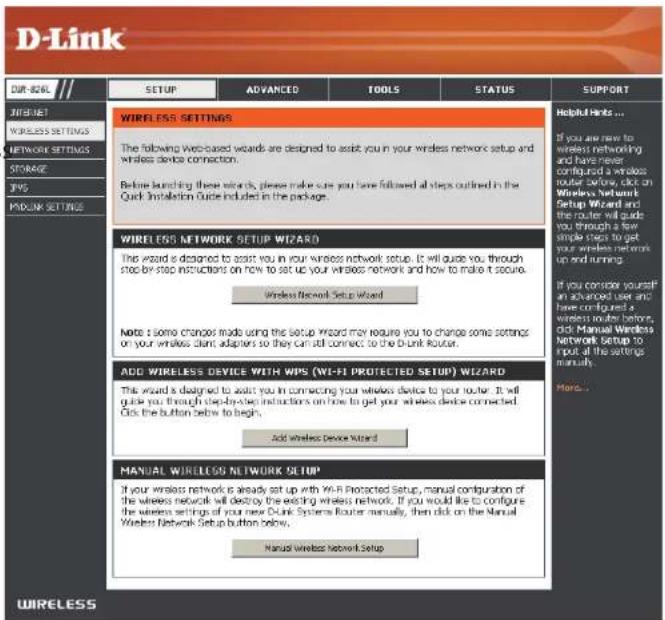
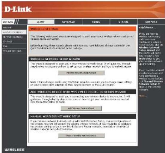
If you want to configure the wireless settings on your router using the wizard, click Wireless.Security.Setup.Wizard.and refer to page 42.
Click Add.Wireless.Device.with.WPS if you want to add a wireless device using Wi-Fi Protected Setup (WPS) and refer to page 44.
If you want to manually configure the wireless settings on your router click Manual Wireless.Network.Setup.and refer to the next page.
text_image
D-Link SETUP ADVANCED TOOLS STATUS SUPPORT WIRELESS SETTINGS The following Web-based words are designed to assist you in your wireless network setup and wireless device connection. Before launching these words, please make sure you have followed all steps outlined in the Quick Installation Guide included in the package. WIRELESS NETWORK SETUP WIZARD The wizard is designed to assist you in your wireless network setup. It will guide you through step-by-step instructions on how to set up your wireless network and how to make it secure. Wireless Network Setup Wizard Note: I some changes made using the setup Wizard may require you to change some settings on your wireless client adapters so they can still connect to the D-Link Router. ADD WIRELESS DEVICE WITH MIPS (WI-FI PROTECTED SETUP) WIZARD This Wizard is designed to assist you in connecting your wireless device to your router. It will guide you through step-by-step instructions on how to get your wireless device connected. Click the button below to begin. Add Wireless Device Wizard MANUAL WIRELESS NETWORK SETUP* If your wireless network is already set up with WI-R Protected Setup, manual configuration of the wireless network will destroy the existing wireless network. If you would like to configure the wireless settings of your new Dublin Systems Router manually, then click on the Manual Wireless Network Setup button below. Manual Wireless Network Setup Helpful Helps... If you are now to wireless networking and have never configured a wireless router before, click on Wireless Network Setup Wizard and the router will guide you through a few simple steps to get your wireless network up and running. If you consider yourself an advanced user and have configured a wireless router before, click Manual Wireless Network Setup to load all the settings manually. More...Manual Wireless Settings
802.11n/g (2.4GHz)
Enable Wireless: Check the box to enable the wireless function. If you do not want to use wireless, uncheck the box to disable all the wireless functions.
Schedule: Select the time frame that you would like your wireless network enabled. The schedule may be set to Always. Any schedule you create will be available in the drop-down menu. Click New Schedule to create a schedule.
Wireless Network Service Set Identifier (SSID) is the name of your wireless network. Create Name: a name for your wireless network using up to 32 characters. The SSID is case-sensitive.
WIRELESS NETWORK SETTINGS
Wireless Band : 2.4GHz Band

Wireless Network Name : dlink (Also called the SSID)
802.11 Mode : Mixed 802.11n, 802.11g and 802.11b
Enable Auto Channel Scan : ☑

Channel Width : Auto 20/40 MHz
Visibility Status : ◎ Visible ○ Invisible
802.11 Mode: Select one of the following:
802.11b Only - Select only if all of your wireless clients are 802.11b.
802.11g Only - Select only if all of your wireless clients are 802.11g.
802.11n Only - Select only if all of your wireless clients are 802.11n.
Mixed 802.11g and 802.11b - Select if you are using both 802.11g and 802.11b wireless clients.
Mixed 802.11n and 802.11g - Select if you are using both 802.11n and 802.11g wireless clients.
Mixed 802.11n, 11g, and 11b - Select if you are using a mix of 802.11n, 802.11g, and 802.11b wireless clients.
Enable Auto Channel The Auto Channel Scan setting can be selected to allow the DIR-826L to choose the channel with the least amount of interference. Scan:
Wireless Channel: Indicates the channel setting for the DIR-826L. By default the channel is set to 6. The Channel can be changed to fit the channel setting for an existing wireless network or to customize the wireless network. If you enable Auto Channel Scan, this option will be greyed out.
Channel Width: Select the Channel Width:
Auto 20/40 - This is the default setting. Select if you are using both 802.11n and non-802.11n wireless devices.
20MHz - Select if you are not using any 802.11n wireless clients.
Visibility Status: Select Invisible if you do not want the SSID of your wireless network to be broadcasted by the DIR-826L. If Invisible is selected, the SSID of the DIR-826L will not be seen by Site Survey utilities so your wireless clients will have to know the SSID of your DIR-826L in order to connect to it.
Wireless Security: Refer to page 41 for more information regarding wireless security.
802.11n/a (5GHz)
Enable Wireless: Check the box to enable the wireless function. If you do not want to use wireless, uncheck the box to disable all the wireless functions.
Schedule: Select the time frame that you would like your wireless network enabled. The schedule may be set to Always. Any schedule you create will be available in the drop-down menu. Click New Schedule to create a schedule.
Wireless Network Service Set Identifier (SSID) is the name of your wireless network. Name: Create a name for your wireless network using up to 32 characters. The SSID is case-sensitive.
802.11 Mode: Select one of the following:
802.11a Only - Select if all of your wireless clients are 802.11a.
802.11n Only - Select only if all of your wireless clients are 802.11n.
Mixed 802.11n and 802.11a - Select if you are using both 802.11n and 802.11a wireless clients.
WIRELESS NETWORK SETTINGS
Wireless Band : 5GHz Band
Enable Wireless : ☑ Always ▼ New Schedule
Wireless Network Name : dlink_media (Also called the SSID)
802.11 Mode : Mixed 802.11n and 802.11a
Enable Auto Channel Scan : ☑
Wireless Channel : 5.180 GHz - CH 36
Channel Width : Auto 20/40 MHz
Visibility Status : ◎ Visible ○ Invisible
Enable Auto Channel The Auto Channel Scan setting can be selected to allow the DIR-826L to choose the channel with the least amount of interference. Scan:
Wireless Channel: Indicates the channel setting for the DIR-826L. By default the channel is set to 6. The Channel can be changed to fit the channel setting for an existing wireless network or to customize the wireless network. If you enable Auto Channel Scan, this option will be greyed out.
Channel Width: Select the Channel Width:
Auto 20/40 - This is the default setting. Select if you are using both 802.11n and non-802.11n wireless devices.
20MHz - Select if you are not using any 802.11n wireless clients.
Visibility Status: Select Invisible if you do not want the SSID of your wireless network to be broadcasted by the DIR-826L. If Invisible is selected, the SSID of the DIR-826L will not be seen by Site Survey utilities so your wireless clients will have to know the SSID of your DIR-826L in order to connect to it.
Wireless Security: Refer to the next page for more information regarding wireless security.
Wireless Security
This section will show you the different levels of security you can use to protect your data from intruders. The DIR-826L offers the following types of security:
- WPA2 (Wi-Fi Protected Access 2) • WPA2-PSK (Pre-Shared Key)
- WPA (Wi-Fi Protected Access) • WPA-PSK (Pre-Shared Key)
What is WPA?
WPA (Wi-Fi Protected Access), is a Wi-Fi standard that was designed to improve the security features of WEP (Wired Equivalent Privacy).
The 2 major improvements over WEP:
- Improved data encryption through the Temporal Key Integrity Protocol (TKIP). TKIP scrambles the keys using a hashing algorithm and, by adding an integrity-checking feature, ensures that the keys haven't been tampered with. WPA2 is based on 802.11i and uses Advanced Encryption Standard (AES) instead of TKIP.
- User authentication, which is generally missing in WEP, through the extensible authentication protocol (EAP). WEP regulates access to a wireless network based on a computer's hardware-specific MAC address, which is relatively simple to be sniffed out and stolen. EAP is built on a more secure public-key encryption system to ensure that only authorized network users can access the network.
WPA-PSK/WPA2-PSK uses a passphrase or key to authenticate your wireless connection. The key is an alpha-numeric password between 8 and 63 characters long. The password can include symbols (!?*&_) and spaces. This key must be the exact same key entered on your wireless router or access point.
WPA/WPA2 incorporates user authentication through the Extensible Authentication Protocol (EAP). EAP is built on a more secure public key encryption system to ensure that only authorized network users can access the network.
Wireless Security Setup Wizard
To run the security wizard, click on Setup at the top and then click Wireless.Network.Setup.Wizard.
text_image
D-Link ZIP: 624L SETUP ADVANCED TOOLS STATUS SUPPORT WIRELESS SETTINGS The following Web-based wireless are designed to start return your wireless network setup and wireless device connection. Before launching these variants, please make sure you have followed all steps outlined in the Quick Installation Guide included in the package. WIRELESS NETWORK SETUP Wizard This ward is designed to assist your wireless network setup. It will guide you through step-by-step instructions on how to set up your wireless network and how to make it secure. Wireless Network Setup Wizard Note: Some changes made using this Setup Wizard may require you to change some settings on your wireless device selection as they can still correct or the Disk Router. ADD WIRELESS DEVICE WITH WIPS (WIFI-FT PROTECTED SETUPS) Wizard This ward is designed to assist your in connecting your wireless device to your router. It will guide you through step-by-step instructions on how to get your wireless device connected. Click the button below to beach. Add Wireless Server Wizard MANUAL WIRELESS NETWORK SETUP If your wireless network is already set up with WIPS Protected Setup, maintain configuration of the wireless network will deliver the matching wireless networks. If you would like to configure the wireless settings of your new Disk Systems Router regularly, then click on the Manual Windows Network Setup button below. Make a Wireless Network Setup.Type your desired wireless network name (SSID).
Automatically:.Select this option to automatically generate the router's network key and click Next.
Manually: Select this option to manually enter your network key and click Next.

text_image
STEP 1: WELCOME TO THE D-LINK WIRELESS SECURITY SETUP WIZARD Give your network a name, using up to 32 characters. Network Name (SSID) 2.4GHz Band: dink. ✓ Manuly set 5GHz band Network Name(SSID) Network Name (SSID) 5GHz Band: dink_media ● Automatically assign a network key for both 2.4GHz and 5GHz band (Recommended) To prevent outsiders from accessing your network, the router will automatically assign a security (also called WEP or WPA key) to your network. ○ Manually assign a network key Use this options if you prefer to create our own key. Note: All D-Link wireless adapters currently support WPA. Prev Next CancelSection 4 - Security
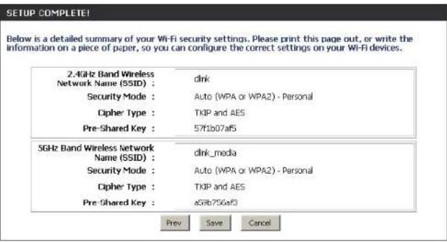
If you selected Automatically, the summary window will display your settings. Write down the security key and enter this on your wireless clients. Click Save to save your settings.
text_image
SETUP COMPLETE! Below is a detailed summary of your Wi-Fi security settings. Please print this page out, or write the information on a piece of paper, so you can configure the correct settings on your Wi-Fi devices. 2.4GHz Band Wireless Network Name (SSID) : dink Security Mode : Auto (WPA or WPA2) - Personal Cipher Type : TKIP and AES Pre-Shared Key : 57f1b07af5 5GHz Band Wireless Network Name (SSID) : dink_media Security Mode : Auto (WPA or WPA2) - Personal Cipher Type : TKIP and AES Pre-Shared Key : a59b756af3 Prev Save CancelIf you selected Manually, the following screen will appear. Create a passphrase for your security password. Click Next to continue.

text_image
STEP 2: SET YOUR WIRELESS SECURITY PASSWORD You have selected your security level - you will need to set a wireless security password. The WPA (Wi-Fi Protected Access) key must meet following guidelines - Between 8 and 63 characters (A longer WPA key is more secure than a short one) - Exactly 64 characters using 0-9 and A-F □ Use the same Wireless Security Password on both 2.4GHz and 5GHz band 2.4GHz Band Wireless Security Password : 5GHz Band Wireless Security Password : Note: You will need to enter the same password as keys in this step into your wireless clients in order to enable proper wireless communication. Prev Next CancelAdd Wireless Device with WPS Wizard
From the Setup > Wireless.Settings screen, click Add.Wireless.Device.with.WPS.
ADD WIRELESS DEVICE WITH WPS (WI-FI PROTECTED SETUP) WIZARD
This wizard is designed to assist you in connecting your wireless device to your router. It will guide you through step-by-step instructions on how to get your wireless device connected. Click the button below to begin.
Add Wireless Device with WPS
Select Auto to add a wireless client using WPS (Wi-Fi Protected Setup) and then click Next. Skip to the next page.
STEP 1: SELECT CONFIGURATION METHOD FOR YOUR WIRELESS NETWORK
Please select one of following configuration methods and click next to continue.
Auto Select this option if your wireless device supports WPS (Wi-Fi Protected Setup)
Manual ○ Select this option will display the current wireless settings for you to configure the wireless device manually.
Next
Cancel
If you select Manual, a settings summary screen will appear. Write down the security key and enter this on your wireless clients. Click OK to finish.

text_image
ADD WIRELESS DEVICE WIZARD (Wi-FI PROTECTED SETUP) Below is a detailed summary of your Wi-Fi security settings. Please print this page out, or write the information on a piece of paper, so you can configure the correct settings on your Wi-Fi devices. 2.4GHz Band SSD: dlink Security Mode: None QUEST ZONE SSD: dlink_guest Security Mode: None 50Hz Band SSD: dlink_media Security Mode: None QUEST ZONE SSD: dlink_media_guest Security Mode: NoneSection 4 - Security
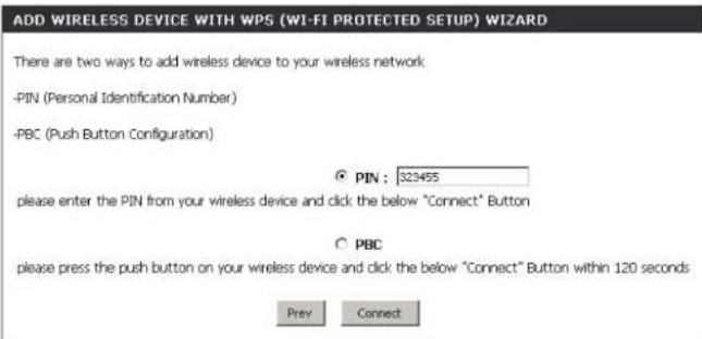
PIN: Select this option to use PIN method. In order to use this method you must know the wireless client's 8 digit PIN and click Connect.
PBC::Select this option to use PBC (Push Button) method to add a wireless client. Click Connect.
Once you click. Connect, you will have a 120 second time limit to apply the settings to your wireless client(s) and successfully establish a connection.
text_image
ADD WIRELESS DEVICE WITH WPS (WI-FI PROTECTED SETUP) WIZARD There are two ways to add wireless device to your wireless network -PIN (Personal Identification Number) -PBC (Push Button Configuration) ● PIN : 323455 please enter the PIN from your wireless device and click the below "Connect" Button ○ PBC please press the push button on your wireless device and click the below "Connect" Button within 120 seconds Prev Connect
text_image
ADD WIRELESS DEVICE WITH WPS Please press down the Push Button (physical or virtual) on the wireless device you are adding to your wireless network within 117 seconds ...WPA/WPA2-Personal (PSK)
It is recommended to enable encryption on your wireless router before your wireless network adapters. Please establish wireless connectivity before enabling encryption. Your wireless signal may degrade when enabling encryption due to the added overhead.
-
Log into the web-based configuration by opening a web browser and entering the IP address of the router (192.168.0.1). Click on. Setup.and then click.Wireless.Settings on the left side.
-
Next to Security Mode, select WPA-Personal.
-
Next to WPA Mode, select Auto, WPA2.Only, or.WPA.Only. Use Auto if you have wireless clients using both WPA and WPA2.
-
Next to Cypher Type, select TKIP.and.AES, TKIP, or AES.
-
Next to Group Key Update Interval, enter the amount of time before the group key used for broadcast and multicast data is changed (3600 is default).
-
Next to Pre-Shared Key, enter a key (passphrase). The key is entered as a pass-phrase in ASCII format at both ends of the wireless connection. The pass-phrase must be between 8-63 characters.
-
Click Save.Settings to save your settings. If you are configuring the router with a wireless adapter, you will lose connectivity until you enable WPA-PSK on your adapter and enter the same passphrase as you did on the router.
WIRELESS SECURITY MODE
To protect your privacy you can configure wireless security features. This device supports three wireless security modes, including WEP, WPA-Personal, and WPA-Enterprise. WEP is the original wireless encryption standard. WPA provides a higher level of security. WPA-Personal does not require an authentication server. The WPA-Enterprise option requires an external RADIUS server.
Security Mode : WPA-Personal
WPA
Use WPA or WPA2 mode to achieve a balance of strong security and best compatibility. This mode uses WPA for legacy clients while maintaining higher security with stations that are WPA2 capable. Also the strongest cipher that the client supports will be used. For best security, use WPA2 Only mode. This mode uses AES(COMP) cipher and legacy stations are not allowed access with WPA security. For maximum compatibility, use WPA Only. This mode uses TKIP cipher. Some gaming and legacy devices work only in this mode.
To achieve better wireless performance use WPA2 Only security mode (or in other words AES cipher).
WPA Mode : Auto (WPA or WPA2)
Cipher Type: TKIP and AES
Group Key Update Interval : 3600 (seconds)
PRE-SHARED KEY
Enter an 8- to 63-character alphanumeric pass-phrase. For good security it should be of ample length and should not be a commonly known phrase.
Pre-Shared Key :
Configure WPA/WPA2-Enterprise (RADIUS)
It is recommended to enable encryption on your wireless router before your wireless network adapters. Please establish wireless connectivity before enabling encryption. Your wireless signal may degrade when enabling encryption due to the added overhead.
- Log into the web-based configuration by opening a web browser and entering the IP address of the router (192.168.0.1). Click on.Setup. and then click.Wireless.Settings on the left side.
- Next to Security Mode, select WPA-Enterprise.
- Next to WPA Mode, select Auto, WPA2.Only, or.WPA.Only. Use Auto if you have wireless clients using both WPA and WPA2.
- Next to Cypher Type, select TKIP.and.AES, TKIP, or AES.
- Next to Group Key Update Interval, enter the amount of time before the group key used for broadcast and multicast data is changed (3600 is default).
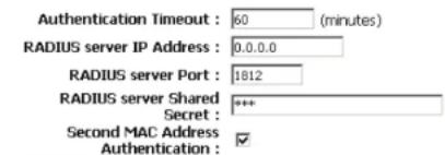
- Next to Authentication Timeout, enter the amount of time before a client is required to re-authenticate (60 minutes is default).
- Next to RADIUS Server IP Address enter the IP Address of your RADIUS server.
WIRELESS SECURITY MODE
To protect your privacy you can configure wireless security features. This device supports three wireless security modes including WEP, WPA-Personal, and WPA-Enterprise. WEP is the original wireless encryption standard. WPA provides a higher level of security. WPA-Personal does not require an authentication server. The WPA-Enterprise option requires an external RADIUS server.
Security Mode : WPA-Enterprise
WPA
Use WPA or WPA2 mode to achieve a balance of strong security and best compatibility. This mode uses WPA for legacy clients while maintaining higher security with stations that are WPA2 capable. Also the strongest cipher that the client supports will be used. For best security, use WPA2 Only mode. This mode uses AES(COMP) cipher and legacy stations are not allowed access with WPA security. For maximum compatibility, use WPA Only. This mode uses TKIP cipher. Some gaming and legacy devices work only in this mode.
To achieve better wireless performance use WPA2 Only security mode (or in other words AES cipher).

EAP (802.1X)
When WPA enterprise is enabled, the router uses EAP (802.1x) to authenticate clients via a remote RADIUS server. MAC Address Authentication
text_image
Authentication Timeout : 60 (minutes) RADIUS server IP Address : 0.0.0.0 RADIUS server Port : 1812 RADIUS server Shared Secret : *** Second MAC Address Authentication : ✓Advanced>>
Section 4 - Security
- Next to RADIUS Server Port, enter the port you are using with your RADIUS server. 1812 is the default port.
- Next to RADIUS Server Shared Secret, enter the security key.
- If the MAC Address Authentication box is selected then the user will need to connect from the same computer whenever logging into the wireless network.
- Click Advanced to enter settings for a secondary RADIUS Server.
- Click Apply.Settings to save your settings.

text_image
EAP (802.1X) When WPA enterprise is enabled, the router uses EAP (802.1x) to authenticate clients via a remote RADIUS server. MAC Address Authentication Authentication Timeout : 60 (minutes) RADIUS server IP Address : 0.0.0.0 RADIUS server Port : 1812 RADIUS server Shared Secret : *** Second MAC Address Authentication : <Network Settings
This section will allow you to change the local network settings of the router and to configure the DHCP settings.Router Settings
Router IP Address: Enter the IP address of the router. The default IP address is 192.168.0.1. If you change the IP address, once you click Save.Settings, you will need to enter the new IP address in your browser to get back into the configuration utility. Subnet Mask: Enter the Subnet Mask. The default subnet mask is 255.255.255.0. Device Name: Enter a name for the router. Local Domain: Enter the Domain name (Optional). Enable DNS Relay: Uncheck the box to transfer the DNS server information from your ISP to your computers. If checked, your computers will use the router for a DNS server.ROUTER SETTINGS
Use this section to configure the internal network settings of your router. The IP Address that is configured here is the IP Address that you use to access the Web-based management interface. If you change the IP Address here, you may need to adjust your PC's network settings to access the network again. text_image
Router IP Address : 192.168.0.1 Subnet Mask : 255.255.255.0 Device Name : dlinkrouter Local Domain Name : Enable DNS Relay : ✓DHCP Server Settings
DHCP stands for Dynamic Host Control Protocol. The DIR-826L has a built-in DHCP server. The DHCP Server will automatically assign an IP address to the computers on the LAN/private network. Be sure to set your computers to be DHCP clients by setting their TCP/IP settings to "Obtain an IP Address Automatically." When you turn your computers on, they will automatically load the proper TCP/IP settings provided by the DIR-826L. The DHCP Server will automatically allocate an unused IP address from the IP address pool to the requesting computer. You must specify the starting and ending address of the IP address pool. Enable DHCP Check this box to enable the DHCP server on your router. Server: Uncheck to disable this function. DHCP IP Address Enter the starting and ending IP addresses for the DHCP server's Range: IP assignment. Note: If you statically (manually) assign IP addresses to your computers or devices, make sure the IP addresses are outside of this range or you may have an IP conflict. DHCP Lease Time: The length of time for the IP address lease. Enter the Lease time in minutes. Always Enable this feature to broadcast your networks DHCP server to Broadcast: LAN/WLAN clients. NetBIOS NetBIOS allows LAN hosts to discover all other computers within an announcement: the network, enable this feature to allow the DHCP Server to offer NetBIOS configuration settings.DHCP SERVER SETTINGS
Use this section to configure the built-in DHCP Server to assign IP addresses to the computers on your network. text_image
Enable DHCP Server : ✓ DHCP IP Address Range : 192.168.0.100 to 192.168.0.199 DHCP Lease Time : 1440 (minutes)Section 3 - Configuration
NetBIOS Node: Select the different type of NetBIOS node; Broadcast.only, Point-to-Point, Mixed-mode, and Hybrid. WINS IP Enter your WINS Server IP address(es). Address:DHCP Reservation
If you want a computer or device to always have the same IP address assigned, you can create a DHCP reservation. The router will assign the IP address only to that computer or device. Note: This IP address must be within the DHCP IP Address Range. Enable: Check this box to enable the reservation. Computer Name: Enter the computer name or select from the drop-down menu and click <<. IP Address: Enter the IP address you want to assign to the computer or device. This IP Address must be within the DHCP IP Address Range. MAC Address: Enter the MAC address of the computer or device. Copy Your PC's If you want to assign an IP address to the computer you MAC Address: are currently on, click this button to populate the fields. Save: Click Save to save your entry. You must click Save.Settings at the top to activate your reservations. text_image
ADD DHCP RESERVATION Enable : ✓ Computer Name : PM_test01 << PM_test01 IP Address : 192.168.0.112 MAC Address : 00:04:23:2c:51:a3 Copy Your PC's MAC Address Save Clear DHCP RESERVATIONS LIST Enable Host Name MAC Address IP Address NUMBER OF DYNAMIC DHCP CLIENTS : 1 Hardware Address Assigned IP Hostname Expires 00:04:23:2c:51:a3 192.168.0.112 PM_test01 Thu Sep 1 19:49:06 2011 Revoke ReserveDHCP Reservations List
DHCP Displays any reservation entries. Displays the host name Reservations List: (name of your computer or device), MAC Address, and IP address. Enable: Check to enable the reservation. Edit: Click the edit icon to make changes to the reservation entry. Delete: Click to remove the reservation from the list. text_image
DHCP RESERVATIONS LIST Enable Host Name MAC Address IP Address ✓ PM_test01 00:04:23:2c:51:a3 192.168.0.112 NUMBER OF DYNAMIC DHCP CLIENTS : 1 Hardware Address Assigned IP Hostname Expires 00:04:23:2c:51:a3 192.168.0.112 PM_test01 Thu Sep 1 19:49:06 2011 Revoke ReserveStorage
This page will allow you to access files from a USB external hard drive or thumb drive that is plugged into the router from your local network or from the Internet using either a web browser or an app for your smartphone or tablet. You can create users to be allowed to access these files. Enable Web File Check to enable sharing files on your USB storage device Access: that is plugged in your router. Enable HTTP Check to enable HTTP access to your router's storage. You Storage Remote will have to type HTTP in the URL. Access: Remote Access Enter a port (8181 is default). You will have to enter this port Port: in the URL when connecting to the shared files. For example: (http://192.168.0.1:8181). Enable HTTPS Check to enable HTTPS (secure) access to your router's Storage Remote storage. You will have to type HTTPS in the URL. Access: Remote HTTPS Enter a port (4433 is default). You will have to enter this port Port: in the URL when connecting to the shared files. For example: (https://192.168.0.1:4433). User Name: To create a new user, enter a user name. Password: Enter a password for this account. Verify Password: Re-enter the password. Click Add/Edit to create the user. User List: Displays the accounts. The Admin and Guest accounts are built-in to the router. Number of Displays the USB device plugged into the router. Devices: text_image
HTTP STORAGE Enable Web File Access : Enable HTTP Storage Remote Access : Remote Access Port : 8181 Enable HTTPS Storage Remote Access : Remote HTTPS Port : 4433text_image
10 -- USER CREATION User Name : < < User Name Password : Verify Password : Add/Edit.| NUMBER OF DEVICE: | ||
| Device | Total Space | Free Space |
| HTTP STORAGE LINK | ||
| You can use this link to connect to the drive remotely after logging in with a user account. | ||
Access Files from the Internet
If you would like to access your files that are on your USB thumb drive or external hard drive that is connected to your router, follow the steps below:Step 1 - Enable Web File Access
Check the Enable Web File Access checkbox to enable. Then select if you want to use HTTP or HTTPS (secure) and enter the port(s) you want to use. The default for HTTP is 8181 and HTTPS is 4433.Step 2 - Create a User Account
Under User Creation, enter a username and password, and then click Add/Edit.Step 3 - Configure your Access Path
Under User List, click the Modify icon for the user you just created. Here you can browse to the folder on your USB storage device you want to assign the Access Path to.Step 4 - Save Settings
If you want to add more users, repeat steps 3 and 4. Once you are finished, click the Save Settings button at the top to save your settings. Note that under the HTTP Storage Link (at the bottom) will display the URL(s) you can use to connect. Also if you selected HTTPS, you must type in HTTPS://instead of HTTP://to get a secure connection. For example, if you selected HTTPS and changed the port to 3200, and your WAN IP address is 1.2.3.4, then you would enter HTTPS://1.2.3.4:3200 to connect. text_image
HTTP STORAGE Enable Web File Access : ✓ Enable HTTP Storage Remote Access : ✓ Remote Access Port : 8181 Enable HTTPS Storage Remote Access : Remote HTTPS Port : 4433 10 -- USER CREATION User Name : << User Name ▼ Password : Verify Password : Add/Edit Delete USER LIST No. User Name Access Path Permission 1 admin / Read/Write 2 guest None Read Only 3 d-link (1) /Storage(B0)/ Read/Write NUMBER OF DEVICES : 1 Device Total Space Free Space Storage(B0) 15.04 GB 14.65 GBIPv6
On this page, the user can configure the IPv6 Connection type. There are two ways to set up the IPv6 Internet connection. You can use the Web-based IPv6 Internet Connection Setup Wizard, or you can manually configure the connection. For the beginner user that has not configured a router before, click on the IPv6.Internet.Connection.Setup.Wizard.button and the router will guide you through a few simple steps to get your network up and running. For the advanced user that has configured a router before, click on the Manual.IPv6.Internet.Connection.Setup button to input all the settings manually. To configure the IPv6 local settings, click on the IPv6.Local.Connectivity. Setup button. text_image
D-Link OR: 60% SETUP ADVANCED ITEMS STATUS SUPPORT IPVs INTERNET CONNECTION There is just what to set up your IPv6 Internet Connection. You can use the website's IPv6 Internet Connection Setup Wizard, or you can further continue the connection. IPVs INTERNET CONNECTION SETUP Wizard (You would like to allow our new user to use Web-based Wrench to send your connection your new Dublin Systems Router to the IPv6 Internet, click on the button below. This Internet Connection Setup Wizard Note: Default launching these words, please make sure you have followed all more widths in the Quick Installation Guide module in the package. MANUAL IPVs LOCAL CONNECTIVITY SETUP (You would like to config your IPv6 local connectivity settings of your Dublin Route, then click on the button below. IPv6 Local Connectivity Settings MANUAL IPVs INTERNET CONNECTION SETUP (You would like to config your IPv6 Internet settings of your new Dublin Systems Router manually, then click on the button below. Personal IPv6 Internet Connection Setup Wireless IPV6 LOCAL CONNECTIVITY SETTINGS Use this section to configure Unique Local IPv6 Unicast Addresses(ULA) settings for your router. ULA is intended for local communications and not expected to be routable on the global Internet. Save Settings Don't Save Settings IPV6 ULA SETTINGS Enable ULA : Use Default: ULA Prefix : ULA Prefix : 04d:8122:19e1:0000: /64 CURRENT IPV6 ULA SETTINGS Current ULA Prefix : LAN IPv6 ULA :IPv6 Internet Connection Setup Wizard
On this page, the user can configure the IPv6 Connection type using the IPv6 Internet Connection Setup Wizard. Click the IPv6.Internet.Connection.Setup.Wizard button and the router will guide you through a few simple steps to get your network up and running.IPV6 INTERNET CONNECTION SETUP WIZARD
If you would like to utilize our easy to use Web-based Wizard to assist you in connecting your new D-Link Systems Router to the IPv6 Internet, click on the button below. IPv6 Internet Connection Setup Wizard Note: Before launching the wizards, please make sure you have followed all steps outlined in the Quick Installation Guide included in the package. Click Next to continue to the next page. Click Cancel to discard the changes made and return to the main page.WELCOME TO THE D-LINK IPV6 INTERNET CONNECTION SETUP WIZARD
This wizard will guide you through a setp-by-setp process to configure a new connection to the IPv6 Interest. \- Step 1: Configure your IPv6 Interest Connection - Step 2: Save setting and connect  The router will try to detect whether its possible to obtain the IPv6 Internet connection type automatically. If this succeeds then the user will be guided through the input of the appropriate parameters for the connection type found.STEP 1: CONFIGURE YOUR IPV6 INTERENT CONNECTION
Router is detecting your IPv6 Interest connection type, please wait.  Section 3 - Configuration
However, if the automatic detection fails, the user will be prompt to either Try. again. or to click on the Guide.me.through.the.IPv6.settings button to initiate the manual continual of the wizard. text_image
STEP 1: CONFIGURE YOUR IPv6 INTERENT CONNECTION Router is unable detect your IPv6 internet connection type Cancel Try again Guide me through the IPv6 settingtext_image
STEP 1: CONFIGURE YOUR IPv6 INTERENT CONNECTION Please select your IPv6 Interent Connection type ● IPv6 over PPPoE Choose this option if your IPv6 Interent connection requires a username and password to get online. Most DSL modems use this type of connection. ○ Static IPv6 address and Route Choose this option if your Interest Service Provider (ISP) provided you with IPv6 address information that has to be manually configured. ○ Tunneling Connection (Grc) Choose this option if your Interest Service Provider (ISP) provided you a IPv6 Internet connection by using Grc automatic tunneling mechanism. Prev Next Cancel CancelIPv6.over.PPPoE
After selecting the IPv6 over PPPoE option, the user will be able to configure the IPv6 Internet connection that requires a username and password to get online. Most DSL modems use this type of connection. The following parameters will be available for configuration: PPPoE.Session: Select the PPPoE Session value used here. This option will state that this connection shares it's information with the already configured IPv6 PPPoE connection, or the user can create a new PPPoE connection here. User.Name: Enter the PPPoE username used here. If you do not know your user name, please contact your ISP. Password: Enter the PPPoE password used here. If you do not know your password, please contact your ISP. Verify.Password:Re-enter the PPPoE password used here. Service.Name: Enter the service name for this connection here. This option is optional. SET USERNAME AND PASSWORD CONNECTION (PPPDE) To set up this connection you will need to have a Username and Password from your IPv6 Internet Service Provider. If you do not have this information, please contact your ISP.  Note: You may also need to provide a Service Name. If you do not have or know this information, please contact your ISP. Static.IPv6.Address.Connection
This mode is used when your ISP provides you with a set IPv6 addresses that does not change. The IPv6 information is manually entered in your IPv6 configuration settings. You must enter the IPv6 address, Subnet Prefix Length, Default Gateway, Primary DNS Server, and Secondary DNS Server. Your ISP provides you with all this information. Use.Link-Local. The Link-local address is used by nodes and routers when Address: communicating with neighboring nodes on the same link. This mode enables IPv6-capable devices to communicate with each other on the LAN side. IPv6.Address: Enter the WAN IPv6 address for the router here. SubnetPrefix. Enter the WAN subnet prefix length value used here. Length: Default.Gateway: Enter the WAN default gateway IPv6 address used here. Primary.IPv6.DNS. Enter the WAN primary DNS Server address used here. Address: Secondary.IPv6. Enter the WAN secondary DNS Server address used here. DNS.Address: LAN.IPv6.Address: These are the settings of the LAN (Local Area Network) IPv6 interface for the router. The router's LAN IPv6 Address configuration is based on the IPv6 Address and Subnet assigned by your ISP. (A subnet with prefix /64 is supported in LAN.) SET STATIC IPV ADDRESS CONNECTION text_image
To set up this connection you will need to have a complete list of IPv6 information provided by your IPv6 Internet Service Provider. If you have a Static IPv6 connection and do not have this information, please contact your ISP. Use Link-Local Address : ✓ IPv6 Address : FE30::218:27FF/FE55:689F Subnet Prefix Length : 44 Default Gateway : Primary DNS Address : Secondary DNS Address : LAN IPv6 Address : /64 Prev Next Cancel Connecttext_image
Assign IPv6 Prefix : None Tunnel Link-Local Address : FE80::C0A8:0102/64 6rd Border Relay IPv4 : Address : IPv6 DNS Server : Prev Next Cancel Correcttext_image
SETUP COMPLETE! The IPv6 Internet Connection Setup Wizard has completed. Click the Connect button to save your settings and reboot the router. Prev Next Cancel ConnectIPv6 Manual Setup
There are several connection types to choose from: Auto Detection, Static IPv6, Autoconfiguration (SLAAC/DHCPv6), PPPoE, IPv6 in IPv4 Tunnel, 6to4, 6rd, and Link-local. If you are unsure of your connection method, please contact your IPv6 Internet Service Provider. Note: If using the PPPoE option, you will need to ensure that any PPPoE client software on your computers has been removed or disabled.Auto Detection
Select Auto.Detection to have the router detect and automatically configure your IPv6 setting from your ISP. text_image
IPv6 CONNECTION TYPE Choose the mode to be used by the router to the IPv6 Internet. My IPv6 Connection is : Auto Detection IPv6 DNS SETTINGS Obtain a DNS server address automatically or enter a specific DNS server address. ○ Cotain a DNS server address automatically ○ Use the following DNS address Primary DNS Server : Secondary DNS Server : LAN IPv6 ADDRESS SETTINGS Use this section to configure the internal network settings of your router. If you change the LAN IPv6 Address here, you may need to adjust your PC network settings to access the network again. Enable DHCP-PD : ✓ LAN IPv6 Address : /64 LAN IPv6 Link Local Address : FE80::21B:E7F:E95:689E/64 ADDRESS AUTOCONFIGURATION SETTINGS Use this section to setup IPv6 Autoconfiguration to assign IP addresses to the computers on your network. You can also enable DHCP-PD to delegate prefixes for router in your LAN. Enable automatic IPv6 address assignment : ✓ Enable Automatic DHCP PD in LAN : ✓ Autoconfiguration Type : SLAC + Stateless DHCPv6 Router Advertisement Lifetime: +10 (minutes)Static IPv6
My IPv6 Connection: Select Static.IPv6 from the drop-down menu. WAN IPv6 Address Enter the address settings supplied by your Internet provider Settings: (ISP). LAN IPv6 Address: Enter the LAN (local) IPv6 address for the router. LAN Link-Local Address: Displays the Router's LAN Link-Local Address. Enable Check to enable the Autoconfiguration feature. Autoconfiguration: Autoconfiguration Type: Select Stateful.(DHCPv6), SLAAC.+.RDNSS or SLAAC.+.Stateless.DHCPv6. IPv6 Address Range Enter the start IPv6 Address for the DHCPv6 range for your Start: local computers. IPv6 Address Range Enter the end IPv6 Address for the DHCPv6 range for your End: local computers. IPv6 Address Lifetime: Enter the IPv6 Address Lifetime (in minutes).IPv6 CONNECTION TYPE
Choose the mode to be used by the router to the IPv6 Internet. My IPv6 Connection is : Static IPv6WAN IPv6 ADDRESS SETTINGS
Enter the IPv6 address information provided by your Internet Service Provider (ISP). text_image
Use Link-Local Address : ✓ IPv6 Address : FE80:218:E7FF:FE95:E89F Subnet Prefix Length : 64 Default Gateway : Primary DNS Server : Secondary DNS Server :LAN IPv6 ADDRESS SETTINGS
Use this section to configure the internal network settings of your router. If you change the LAN IPv6 Address here, you may need to adjust your PC network settings to access the network again. LAN IPv6 Address : /64 LAN IPv6 Link-Local Address : FE80::218:E7FF:FE95:689E/64ADDRESS AUTOCONFIGURATION SETTINGS
Use this section to setup IPv6 Autoconfiguration to assign IP addresses to the computers on your network. Autoconfiguration
My IPv6 Connection: Select Autoconfiguration.(Stateless/DHCPv6) from the drop-down menu. IPv6 DNS Settings: Select either Obtain.DNS.server.address.automatically or Use.the.following.DNS.Address. Primary/Secondary DNS Enter the primary and secondary DNS server addresses. Address: LAN IPv6 Address: Enter the LAN (local) IPv6 address for the router. LAN Link-Local Address: Displays the Router's LAN Link-Local Address. Enable Check to enable the Autoconfiguration feature. Autoconfiguration: Autoconfiguration Type: Select Stateful.(DHCPv6), SLAAC.+.RDNSS or SLAAC.+.Stateless.DHCPv6. IPv6 Address Range Enter the start IPv6 Address for the DHCPv6 range for your Start: local computers. IPv6 Address Range Enter the end IPv6 Address for the DHCPv6 range for your End: local computers. IPv6 Address Lifetime: Enter the IPv6 Address Lifetime (in minutes).IPv6 CONNECTION TYPE
Choose the mode to be used by the router to the IPv6 Internet. My IPv6 Connection is : Autoconfiguration (SLAAC/DHCPv6)IPv6 DNS SETTINGS
Obtain a DNS server address automatically or enter a specific DNS server address. Obtain a DNS server address automatically ○ Use the following DNS address Primary DNS Server : Secondary DNS Server :LAN IPv6 ADDRESS SETTINGS
Use this section to configure the internal network settings of your router. If you change the LAN IPv6 Address here, you may need to adjust your PC network settings to access the network again. Enable DHCP-PD : ☑ LAN IPv6 Address : /64 LAN IPv6 Link-Local Address : FE80::218:E7FF:FE95:689E/64ADDRESS AUTOCONFIGURATION SETTINGS
Use this section to setup IPv6 Autoconfiguration to assign IP addresses to the computers on your network. You can also enable DHCP-PD to delegate prefixes for router in your LAN. Enable automatic IPv6 address assignment Enable Automatic DHCP-PD in LAN: Autoconfiguration Type: SLAAC + Stateless DHCPv6 Router Advertisement Lifetime: 1440 (minutes)PPPoE
My IPv6 Connection: Select PPPoE from the drop-down menu. PPPoE: Enter the PPPoE account settings supplied by your Internet provider (ISP). Address Mode: Select Static if your ISP assigned you the IP address, subnet mask, gateway, and DNS server addresses. In most cases, select Dynamic. IP Address: Enter the IP address (Static PPPoE only). User Name: Enter your PPPoE user name. Password: Enter your PPPoE password and then retype the password in the next box. Service Name: Enter the ISP Service Name (optional). Reconnection Mode: Select either Always-on, On-Demand, or Manual. Maximum Idle Time: Enter a maximum idle time during which the Internet connection is maintained during inactivity. To disable this feature, enable Auto-reconnect. MTU: Maximum Transmission Unit - you may need to change the MTU for optimal performance with your specific ISP. 1492 is the default MTU. IPv6 DNS Settings: Select either Obtain.DNS.server.address.automatically or Use.the.following.DNS.Address. Primary/Secondary DNS Enter the primary and secondary DNS server addresses. Address: LAN IPv6 Address: Enter the LAN (local) IPv6 address for the router. LAN Link-Local Address: Displays the Router's LAN Link-Local Address. Enable Autoconfiguration: Check to enable the Autoconfiguration feature.IPv6 CONNECTION TYPE
Choose the mode to be used by the router to the IPv6 Internet. My IPv6 Connection is : PPPcEFPPOE
Enter the information provided by your Internet Service Provider (ISP). text_image
PPPoE Session: Share with IPv4 Create a new session Address Mode: Dynamic IP Static IP IP Address: Username: Password: Notify Password: Service Name: Optional Connect Mode: Always on On demand Manual Minimum Idle Time: 5 (minutes, 0=infinite) MTU: 1492 (bytes/MTU default = 1492)IPv6 DNS SETTINGS
Obtain a DNS server address automatically or enter a specific DNS server address. Obtain a DNS server address automatically C. Use the following DNS address Primary DNS Server : Secondary DNS Server :LAN IPv6 ADDRESS SETTINGS
Use this section to configure the internal network settings of your router. If you change the LAN IPv6 Address here, you may need to adjust your PC network settings to access the network again. Enable DHCP-PD: LAN IPv6 Address : /64 LAN IPv6 Link Local Address : F000::210:E7FF:FE95:609€/64ADDRESS AUTOCONFIGURATION SETTINGS
Use this section to setup IPv5 Autoconfiguration to assign IP addresses to the computers on your network. You can also enable DHCP-PD to delegate prefixes for router in your LAN. Enable automatic IPv6 address assignment : Enable Automatic DHCP-PD in Autoconfiguration Type : SLAAC + Stateless DHCPv6 Router Advertisement 1540 (in minutes) Lifetime:Section 3 - Configuration
Autoconfiguration Type: Select Stateful.(DHCPv6), SLAAC.+.RDNSS or SLAAC.+.Stateless.DHCPv6. IPv6 Address Range Start: Enter the start IPv6 Address for the DHCPv6 range for your local computers. IPv6 Address Range End: Enter the end IPv6 Address for the DHCPv6 range for your local computers. IPv6 Address Lifetime: Enter the IPv6 Address Lifetime (in minutes).IPv6 in IPv4 Tunneling
My IPv6 Select IPv6.in.IPv4.Tunnel from the drop-down menu. Connection: IPv6 in IPv4 Tunnel Enter the settings supplied by your Internet provider (ISP). Settings: LAN IPv6 Address: Enter the LAN (local) IPv6 address for the router. LAN Link-Local Displays the Router's LAN Link-Local Address. Address: Enable Check to enable the Autoconfiguration feature. Autoconfiguration: Autoconfiguration Select Stateful.(DHCPv6), SLAAC.+.RDNSS or SLAAC.+.Stateless. Type: DHCPv6. IPv6 Address Enter the start IPv6 Address for the DHCPv6 range for your local Range Start: computers. IPv6 Address Enter the end IPv6 Address for the DHCPv6 range for your local Range End: computers. Pv6 Address Enter the Router Advertisement Lifetime (in minutes). Lifetime:IPv6 CONNECTION TYPE
Choose the mode to be used by the router to the IPv6 Internet. My IPv6 Connection is : IPv6 in IPv4 TunnelIPv6 in IPv4 TUNNEL SETTINGS
Enter the IPv6 in IPv4 Tunnel information provided by your Tunnel Broker. IPv6 DNS SETTINGS
Obtain a DNS server address automatically or enter a specific DNS server address. Obtain a DNS server address automatically ○ Use the following DNS address LAN IPv6 ADDRESS SETTINGS
Use this section to configure the internal network settings of your router. If you change the LAN IPv6 Address here, you may need to adjust your PC network settings to access the network again. ADDRESS AUTOCONFIGURATION SETTINGS
Use this section to setup IPv6 Autoconfiguration to assign IP addresses to the computers on your network. You can also enable DHCP-PD to delegate prefixes for router in your LAN. Enable automatic IPv6 address assignment Enable Automatic DHCP-PD in Autoconfiguration Type : SLAAC + Stateless DHCPv6 6 to 4 Tunneling
My IPv6 Connection: Select 6.to.4 from the drop-down menu. 6 to 4 Settings: Enter the IPv6 settings supplied by your Internet provider (ISP). Primary/Secondary Enter the primary and secondary DNS server addresses. DNS Address: LAN IPv6 Address: Enter the LAN (local) IPv6 address for the router. LAN Link-Local Displays the Router's LAN Link-Local Address. Address: Enable Check to enable the Autoconfiguration feature. Autoconfiguration: Autoconfiguration Select Stateful.(DHCPv6), SLAAC.+.RDNSS or SLAAC.+.Stateless. Type: DHCPv6. IPv6 Address Range Enter the start IPv6 Address for the DHCPv6 range for your local Start: computers. IPv6 Address Range Enter the end IPv6 Address for the DHCPv6 range for your local End: computers. IPv6 Address Enter the IPv6 Address Lifetime (in minutes). Lifetime: text_image
IPv6 CONNECTION TYPE Choose the mode to be used by the router to the IPv6 Internet. My IPv6 Connection is : 6to4 6to4 SETTINGS Enter the IPv6 address information provided by your Internet Service Provider (ISP). 6to4 Address : 2002:COAB:0102::COAB:0102 6to4 Relay : 192.88.99.1 Primary DNS Server : Secondary DNS Server :6rd
My IPv6 Connection: Select 6rd from the drop-down menu. 6RD Settings: Enter the address settings supplied by your Internet provider (ISP). LAN IPv6 Address: Enter the LAN (local) IPv6 address for the router. LAN Link-Local Address: Displays the Router's LAN Link-Local Address. Enable Check to enable the Autoconfiguration feature. Autoconfiguration: Autoconfiguration Type: Select Stateful (DHCPv6), SLAAC+RDNSS or SLAAC + Stateless DHCPv6. Router Advertisement Enter the Router Advertisement Lifetime (in minutes). Lifetime:IPv6 CONNECTION TYPE
Choose the mode to be used by the router to the IPv6 Internet. My IPv6 Connection is : 6rd6RD SETTINGS
Enter the IPv6 address information provided by your Internet Service Provider (ISP).  LAN IPv6 ADDRESS SETTINGS
Use this section to configure the internal network settings of your router. If you change the LAN IPv6 Address here, you may need to adjust your PC network settings to access the network again. LAN IPv6 Address : None LAN IPv6 Link-Local Address : FE80::218:E7FF:FE95:689E/64ADDRESS AUTOCONFIGURATION SETTINGS
Use this section to setup IPv6 Autoconfiguration to assign IP addresses to the computers on your network. Link-Local Connectivity
My IPv6 Connection: Select Link-Local.Only from the drop-down menu. LAN IPv6 Address Displays the IPv6 address of the router. Settings:IPv6 CONNECTION TYPE
Choose the mode to be used by the router to the IPv6 Internet. My IPv6 Connection is : Local Connectivity OnlyLAN IPv6 ADDRESS SETTINGS
LAN IPv6 address for local IPv6 communications. LAN IPv6 Link-Local Address : FE80::218:E7FF:FE95:689E/64mydlink Settings
mydlink Service: Displays whether your device is registered with a mydlink account or not. Register mydlink Click to go to the mydlink website to register or edit your Settings: settings. text_image
D-Link OR-ONE SETUP ADVANCED TOOLS STATUS SUPPORT INTEREST MYDLINK SETTINGS Setting and registering your product with mylink will allow you to use to mylink cloud services features, including online access and management of your device through mylink portal website. Save Settings Don't Save Settings HYDLINK mydlink Service : Non-Registered REGISTER MYDLINK SERVICE Register mydlink Service Helpful Links... None... WIRELESSAdvanced
Virtual Server
This will allow you to open a single port. If you would like to open a range of ports, refer to the next page. Name: Enter a name for the rule or select an application from the drop-down menu. Select an application and click << to populate the fields. IP Address: Enter the IP address of the computer on your local network that you want to allow the incoming service to. If your computer is receiving an IP address automatically from the router (DHCP), you computer will be listed in the "Computer Name" drop-down menu. Select your computer and click <<. Private Port/ Enter the port that you want to open next to Private Public Port: Port and Public Port. The private and public ports are usually the same. The public port is the port seen from the Internet side, and the private port is the port being used by the application on the computer within your local network. Protocol Type: Select TCP, UDP, or Both.from the drop-down menu. Schedule: The schedule of time when the Virtual Server Rule will be enabled. The schedule may be set to Always, which will allow the particular service to always be enabled. You can create your own times in the Tools > Schedules section. Inbound Filter: Select Allow.All (most common) or a created Inbound filter. You may create your own inbound filters in the Advanced.>.Inbound.Filter page. text_image
D-Link DIR-826L SETUP ADVANCED TOOLS STATUS SUPPORT VIRTUAL SERVER The Virtual Server option allows you to define a single public port on your router for redirection to an internal LAN IP Address and Private LAN port if required. The feature is useful for hosting online services such as FTP or Web Servers. Save Settings Don't Save Settings 24—VIRTUAL SERVERS LIST Name << Application Name Port Private Port Public Port Protocol TCP Schedule Always IP Address 0.0.0.0 << Computer Name Private Port Public Port Protocol TCP Inbound Filter Allow All Name << Application Name Private Port Public Port Protocol TCP Schedule Always IP Address 0.0.0.0 << Computer Name Private Port Public Port Protocol TCP Schedule Always IP Address 0.0.0.0 << Computer Name Private Port Public Port Protocol TCP Inbound Filter Allow All Helpful Hinks ... Check the Application Name drop down menu for a list of predefined server types, if you select one of the predefined server types, click the arrow button next to the drop down menu to fill out the corresponding false. You can select a computer from the list of DHCP clients in the Computer Name drop down menu, or you can manually enter the IP address of the computer at which you would like to open the specified port. Select a schedule for when the virtual server will be enabled, if you do not see the schedule you need in the list of schedules, go to the Tools → schedules screen and create a new schedule. Select a filter that restricts the Internet hosts that can accessPort Forwarding
This will allow you to open a single port or a range of ports. Name: Enter a name for the rule or select an application from the drop-down menu. Select an application and click << to populate the fields. IP Address: Enter the IP address of the computer on your local network that you want to allow the incoming service to. If your computer is receiving an IP address automatically from the router (DHCP), you computer will be listed in the "Computer Name" drop-down menu. Select your computer and click <<. TCP/UDP: Enter the TCP and/or UDP port or ports that you want to open. You can enter a single port or a range of ports. Separate ports with a common. Example: 24,1009,3000-4000 Schedule: The schedule of time when the Virtual Server Rule will be enabled. The schedule may be set to Always, which will allow the particular service to always be enabled. You can create your own times in the Tools > Schedules section. Inbound Filter: Select Allow.All (most common) or a created Inbound filter. You may create your own inbound filters in the Advanced.>.Inbound.Filter page. text_image
D-Link DIR-02XL SETUP ADVANCED TOOLS STATUS SUPPORT VIRTUAL SERVER PORT FORWARDING The option is used to open multiple ports or a range of ports in your router and redirect data through those ports to a single PC on your network. The feature allows you to enter ports in various formats including: Port Ranges (100-150), Individual Ports (90, 60, 999), or Mixed (1000-5000, 609). Save Settings Don't Save Settings 24--PORT FORWARDING RULES Name << Application Name TCP Schedule Always Advanced Wireless IP Address 0.0.0.0 << Computer Name UDP Inbound Filter Allow All WiFi PROTECTED SETUP Name << Application Name TCP Schedule Always Advanced Network IP Address 0.0.0.0 << Computer Name UDP Inbound Filter Allow All QUEST ZONE IPW FIREWALL RULES IPW ROUTING Name << Application Name TCP Schedule Always Select a schedule for when the rule will be enabled. If you do not see the schedule you need in the list of Helpful Hints ... Check the Application Name drop down menu for a list of credentials applications. If you select one or the ordered third, they apply, click the show button next to the drop down menu to fill out the corresponding field. You can select a computer from the list of OIMP clients in the Computer Name drop down menu, or you can manually enter the IP address or the LAN computer to which you would like to open the specified port. Select a schedule for when the rule will be enabled. If you do not see the schedule you need in the list ofApplication Rules
Some applications require multiple connections, such as Internet gaming, video conferencing, Internet telephony and others. These applications have difficulties working through NAT (Network Address Translation). Special Applications makes some of these applications work with the DIR-826L. If you need to run applications that require multiple connections, specify the port normally associated with an application in the "Trigger Port" field, select the protocol type as TCP or UDP, then enter the firewall (public) ports associated with the trigger port to open them for inbound traffic. The DIR-826L provides some predefined applications in the table on the bottom of the web page. Select the application you want to use and enable it. Name: Enter a name for the rule. You may select a pre-defined application from the drop-down menu and click <<. Trigger: This is the port used to trigger the application. It can be either a single port or a range of ports. Traffic Type: Select the protocol of the trigger port (TCP, UDP, or Both). Firewall: This is the port number on the Internet side that will be used to access the application. You may define a single port or a range of ports. You can use a comma to add multiple ports or port ranges. Traffic Type: Select the protocol of the firewall port (TCP, UDP, or Both). Schedule: The schedule of time when the Application Rule will be enabled. The schedule may be set to Always, which will allow the particular service to always be enabled. You can create your own times in the Tools > Schedules section. text_image
DIR-826L SETUP ADVANCED TOOLS STATUS SUPPORT VIRTUAL SERVER PORT FORWARDING APPLICATION RULES QOS ENGINE NETWORK FILTER ACCESS CONTROL WEBSITE FILTER INBOUND FILTER FIREWALL SETTINGS ROUTING ADVANCED WINELESS WLP-PROTECTED SETUP ADVANCED NETWORK QUEST ZONE IPW FIREWALL RULES IPW ROUTING APPLICATION RULES This option is used to open single or multiple ports on your router when the router senses data sent to the Internet on a "trigger" port or port range. Special Applications rules apply to all computers on your internal network. Save Settings Don't Save Settings 24 — APPLICATION RULES Port Traffic Type Schedule Trigger 0 TCP Always Application Name Application Name Trigger 0 TCP Always Name Application Name Trigger 0 TCP Always Application Name drop down menu for a list of predefined applications. If you select one of the predefined applications, click the arrow down next to the oroo down menu to fill out the corresponding field. Name Application Name Trigger 0 TCP Always Application Name will be enabled. If you do not see the schedule you need in the list of schedules, go to the tools—schedulesQoS Engine
The QoS Engine option helps improve your network gaming performance by prioritizing applications. By default the QoS Engine settings are disabled and application priority is not classified automatically. Enable QoS Engine: This option is disabled by default. Enable this option for better performance and experience with online games and other interactive applications, such as VoIP.Automatic Uplink
Speed: This option is enabled by default when the QoS Engine option is enabled. This option will allow your router to automatically determine the uplink speed of your Internet connection. Measured Uplink This displays the detected uplink speed. Speed: Manual Uplink Speed: The speed at which data can be transferred from the router to your ISP. This is determined by your ISP. ISP's often speed as a download/upload pair. For example, 1.5Mbits/284Kbits. Using this example, you would enter 284. Alternatively you can test your uplink speed with a service such as speedtest.net. QoS Engine Rules: A QoS Engine Rule identifies a specific message flow and assigns a priority to that flow. For most applications, automatic classification will be adequate, and specific QoS Engine Rules will not be required. The QoS Engine supports overlaps between rules, where more than one rule can match for a specific message flow. If more than one rule is found to match the rule with the highest priority will be used. text_image
QOS ENGINE SETUP Enable QoS Engine : Automatic Uplink Speed : Measured Uplink Speed : Not Estimated Manual Uplink Speed : 128 kbps << Select Transmission Ratetext_image
10 -- QOS ENGINE RULES Name Priority Protocol 1 (1..255) % << TCP Local IP Range Local Port Range 0.0.0.0_to 255.255.255.255 0_to/6553S Remote IP Range Remote Port Range 0.0.0.0_to 255.255.255.255 0_to/6553S Name Priority Protocol % << TCP Local IP Range Local Port Range 0.0.0.0_to 255.255.255.255 0_to/6553S Remote IP Range Remote Port Range 0.0.0.0_to 255.255.255.255 0_to/6553SNetwork Filters
Use MAC (Media Access Control) Filters to allow or deny LAN (Local Area Network) computers by their MAC addresses from accessing the network. You can either manually add a MAC address or select the MAC address from the list of clients that are currently connected to the Broadband Router. Configure MAC Select.Turn.MAC.Filtering.Off, Allow.MAC.addresses. Filtering: listed.below, or Deny.MAC.addresses.listed.below from the drop-down menu. MAC Address: Enter the MAC address you would like to filter. To find the MAC address on a computer, please refer to the Networking Basics section in this manual. DHCP Client: Select a DHCP client from the drop-down menu and click << to copy that MAC Address. Clear: Click to remove the MAC address. text_image
D-Link DIR-826L SETUP ADVANCED TOOLS STATUS SUPPORT VIRTUAL SERVER PORT FORWARDING APPLICATION RULES QOS ENGINE NETWORK FILTER ACCESS CONTROL WEBSITE FILTER INDBOUND FILTER FIREWALL SETTINGS ROUTING ADVANCED WIRELESS WIFI PROTECTED SETUP ADVANCED NETWORK GUEST ZONE IPV6 FIREWALL RULES IPV6 ROUTING MAC ADDRESS FILTER The MAC (Media Access Controller) Address filter option is used to control network access based on the MAC Address of the network adapter. A MAC address is a unique ID assigned by the manufacturer of the network adapter. This feature can be configured to ALLOW or DBV network/Internet access. Save Settings Don't Save Settings Helpful Hints... Create a list of MAC addresses that you would either like to allow or deny access to your network. Computers that have obtained an IP address from the router's DHCP server will be in the DHCP Client List. Select a device from the drop down menu, then click the arrow to add that device's MAC address to the list. Click the Clear button to remove the MAC address from the MAC Filtering list. More...Access Control
The Access Control section allows you to control access in and out of your network. Use this feature as Parental Controls to only grant access to approved sites, limit web access based on time or dates, and/or block access from applications like P2P utilities or games. Add Policy: Click the Add.Policy button to start the Access Control Wizard. text_image
D-Link DIR: $250 VIRUAL SERVER PORT FORWINDING APPLICATION ITEMS QOST PAVES NETWORK FILTER ACCESS CONTROL WEBSITE FILTER BOUND FILTER FIREWALL SETTINGS ROUTING ADVANCED WINDOWS WEET PROTECTED SETUP ADVANCED NETWORK GUEST ZONE SPY PROCESIL RULES SPY ROUTING SETUP ADVANCED TOOLS STATUS SUPPORT ACCESS CONTROL The Access Control option allows you to control access in and out of your network. Use this feature as Access Controls to only grant access to sponsored sites, limit web access based on time or dates, and/or block Internet access for applications like TCP utilities or games. Save Settings Don't Save Settings ACCESS CONTROL Enable Access Control: Add Policy POLICY TABLE Enable Policy Machine Filtering Looped Schedule Helpful hints... Check Enable Access Control if you want to enforce rules that link Internet access from specific LAN-compliant. Click Add Policy to start the processor of creating a rule, you can cancel the process at any time. When you are finished, calling a rule it will be done to the Policy Table below. Click the Edit icon to modify an existing rule using the Policy Wizard. Click the Delete icon to permanently remove a rule.Access Control Wizard
Click Next to continue with the wizard. text_image
ADD NEW POLICY This wizard will guide you through the following steps to add a new policy for Access Control. Step 1 - Choose a unique name for your policy Step 2 - Select: a schedule Step 3 - Select: the machine to which this policy applies Step 4 - Select: filtering method Step 5 - Select: filters Step 5 - Configure Web Access Logging Next Save CancelSection 3 - Configuration
Enter a name for the policy and then click Next to continue. Select a schedule (I.E. Always) from the drop-down menu and then click Next to continue. Enter the following information and then click Next to continue. - Address.Type - Select IP address, MAC address, or Other Machines. - IP.Address - Enter the IP address of the computer you want to apply the rule to. - MachineAddress - Enter the PC MAC address (i.e. 00:00.00.00.00). Select the filtering method and then click Next to continue. text_image
STEP 1: CHOOSE POLICY NAME Choose a unique name for your policy. Policy Name : Example Play Next Canceltext_image
STEP 2: SELECT SCHEDULE Choose a schedule to apply to this schedule. Details: Help Canceltext_image
STEP 3: SELECT MACHINE Select the machine to which this policy applies. Specify a machine with IP or MAC address, or select "Other Machines" for machines that do not have a policy. Address Type: IP C: MAC C: Other Machines IP Address: 100.168.0.112 Machine Address: Do Use Machine 100.168.0.112 OK Cancel Finish Next Canceltext_image
STEP 4: SELECT FILTERING METHODS Select the method for filtering. Method: C Log Web Access Only C Back All Access & Back Some Access Apply Web Filter: Apply Advanced Port Filters: Free Next Save CancelSection 3 - Configuration
Enter the rule:
Enable - Check to enable the rule. Name - Enter a name for your rule. Dest.IP.Start - Enter the starting IP address. Dest.IP.End - Enter the ending IP address. Protocol - Select the protocol. Dest.Port.Start - Enter the starting port number. Dest.Port.End - Enter the ending port number. To enable web logging, click Enable. Click Save to save the access control rule. text_image
ADD TO POINT FILTER Add Port Filter Rules. Apply size to publish ports to specific IP addresses and ports. Name: Start Date End Date Description: Start Date End Date Name: Start Date End Date Name: Start Date End Date Name: Start Date End Date Name: Start Date End Date Name: Start Date End Date Name: Start Date End Date Name: Start Date End Date Name: Start Date End Date Name: Start Date End Date Name: Start Date End Date Name: Start Date End Date Name: Start Date End Date Name: Start Datetext_image
ACCESS CONTROL The Access Control option allows you to control access in and cut out of your network. Use the features as Access controls to only grant access to approved sites, limit web access based on time or dates, and/or block internet access for applications like Web unitless or games. Save Settings Don't Save Settings Reduce Now ENABLE Enable Access Control : Add Policy POLICY TABLE Enable Policy Machine Filtering Logged Schedule ✓ dirk 192.180.0 LD6 Block Some Access No AlwaysWebsite Filters
Website Filters are used to allow you to set up a list of Web sites that can be viewed by multiple users through the network. To use this feature select to Allow or Deny, enter the domain or website and click Save.Settings. You must also select Apply.Web.Filter under the Access Control section. Add Website Select either DENY.computers.access.to.ONLY. Filtering Rule: these.sites or ALLOW.computers.access.to.ONLY these.sites. Website URL/ Enter the keywords or URLs that you want to allow Domain: or block. Click Save.Settings. text_image
DIR-826L SETUP ADVANCED TOOLS STATUS SUPPORT VIRTUAL SERVER PORT FORWARDING APPLICATION RULES QGEN ENGINE NETWORK FILTER ACCESS CONTROL WEBSITE FILTER 10 - WEBSITE FILTERING RULES Configure Website Filter below: DENY computers access to ONLY these sites Clear the list below... Website URL / Domain Helpful Flints... Create a list of Web Sites to which you would like to deny or allow through the network. Use with Advanced Access Control, More... INBOUND FILTER FIREWALL SETTINGS ROUTING ADVANCED WIRELESS WEL-PL PROTECTED SETUP ADVANCED NETWORK GUEST ZONE JPVS FIREWALL RULES JPVS ROUTINGInbound Filters
The Inbound Filter option is an advanced method of controlling data received from the Internet. With this feature you can configure inbound data filtering rules that control data based on an IP address range. Inbound Filters can be used with Virtual Server, Port Forwarding, or Remote Administration features. Name: Enter a name for the inbound filter rule. Action: Select Allow or Deny. Enable: Check to enable rule. Remote IP Start: Enter the starting IP address. Enter 0.0.0.0 if you do not want to specify an IP range. Remote IP End: Enter the ending IP address. Enter 255.255.255.255 if you do not want to specify and IP range. Add: Click the Add button to apply your settings. You must click Save.Settings at the top to save the settings. Inbound Filter This section will list any rules that are created. You Rules List: may click the Edit icon to change the settings or enable/disable the rule, or click the Delete icon to remove the rule. text_image
DIR-826 SETUP ADVANCED TOOLS STATUS SUPPORT INBOUND FILTER The Inbound Filter option is an advanced method of controlling data received from the Internet. With this feature you can configure inbound data filtering rules that control data based on an IP address range. Inbound Filters can be used for limiting access to a server on your network to a system or group of systems. Filter rules can be used with Virtual Server, Port Forwarding, or Remote Administration features. ADD INBOUND FILTER RULE Name: Action: Allow > Remote IP Range : Enable Remote IP Start Remote IP End 0.0.0.0 255.255.255.255 0.0.0.0 255.255.255.255 0.0.0.0 255.255.255.255 0.0.0.0 255.255.255.255 0.0.0.0 255.255.255.255 0.1.0.0 255.255.255.255 0.0.0.0 255.255.255.255 Add Clear INBOUND FILTER RULES LIST Name Action Remote IP Range Helpful Hints ... Give each rule a Name that is meaningful to you. Each rule can either Allow or Deny access from the WAN. Up to eight ranges of WAN IP addresses can be controlled by each rule. The checkbox by each IP range can be used to enable ranges already defined. The routing and ending IP addresses are WAN side address. Click the Add or Update button to store a finished rule in the Rules List below. Click the Edit icon in the Rules List to change a rule. Click the Delete icon in the Rules List to permanently remove a rule. More... WIRELESSFirewall Settings
A firewall protects your network from the outside world. The DIR-826L offers a firewall type functionality. The SPI feature helps prevent cyber attacks. Sometimes you may want a computer exposed to the outside world for certain types of applications. If you choose to expose a computer, you can enable DMZ. DMZ is short for Demilitarized Zone. This option will expose the chosen computer completely to the outside world. Enable SPI: SPI (Stateful Packet Inspection, also known as dynamic packet filtering) helps to prevent cyber attacks by tracking more state per session. It validates that the traffic passing through the session conforms to the protocol. Anti-Spoof Check: Enable this feature to protect your network from certain kinds of "spoofing" attacks. Enable DMZ: If an application has trouble working from behind the router, you can expose one computer to the Internet and run the application on that computer. Note: Placing a computer in the DMZ may expose that computer to a variety of security risks. Use of this option is only recommended as a last resort. DMZ IP Address: Specify the IP address of the computer on the LAN that you want to have unrestricted Internet communication. If this computer obtains it's IP address automatically using DHCP, be sure to make a static reservation on the Setup > Network.Settings page so that the IP address of the DMZ machine does not change. text_image
D-Link DR-8001 SETUP ADVANCED TOOLS STATUS SUPPORT Helding Links... Enable the DNT option only as a last resort, if you are having trouble using or optional from an optional beyond the router, first is following your associated with the application in the Initial Service or The Forwarding Sections. Place... Firewall Settings Firewall Settings The Firewall Settings allow you to set a single computer on your network outside of the router. Save Settings Done Save Settings ENABLE SPI Enable SPI: ANTI SPOOF CHECKING Enable anti-spoof checking: DMZ HOST The DMZ (Unprotected zone) option lets you set a single computer on your network outside of the router. If you have a computer that cannot run Internet applications successfully from behind the router, then you can place the computer into the DMZ for unrestricted Internet access. Notes: Putting a computer in the DMZ may expose that computer to a safety of security risks. Use of the option is only recommended as a last resort. Enable DMZ: DMZ IP Address: 0.0.0 Computer Name: APPLICATION LEVEL GATEWAY (ALS) CONFIGURATION POTP: ✓ L2TP: ✓ PSBAC (WPA): ✓ RTP: ✓ SP: ✓ WIRELESSRouting
The Routing option is an advanced method of customizing specific routes of data through your network. Name: Enter a name for your route. Destination IP: Enter the IP address of packets that will take this route. Netmask: Enter the netmask of the route, please note that the octets must match your destination IP address. Gateway: Enter your next hop gateway to be taken if this route is used. Metric: The route metric is a value from 1 to 16 that indicates the cost of using this route. A value 1 is the lowest cost and 15 is the highest cost. Interface: Select the interface that the IP packet must use to transit out of the router when this route is used. text_image
D-Link DIR-826L SETUP ADVANCED TOOLS STATUS SUPPORT VIRTUAL SERVER PORT FORWARDING APPLICATION RULES QGENEINE NETWORK FILTER ACCESS CONTROL WEBSITE FILTER BOUND FILTER FIREWALL SETTINGS ROUTING ADVANCED WIRELESS WIFI PROTECTED SETUP ADVANCED NETWORK GUEST ZONE JPX FIREWALL RULES JPX ROUTING ROUTING: The ROUTING page allows you to specify custom routes that determine how data is moved around your network. Save Settings Don't Save Settings 32 --ROUTE LIST Metric Interface Name Destination IP 0.0.0.0 Netmask Gateway 0.0.0.0 Name Destination IP 0.0.0.0 Netmask Gateway 0.0.0.0 Name Destination IP 0.0.0.0 Netmask Gateway 0.0.0.0 Name Destination IP 0.0.0.0 Netmask Gateway 0.0.0.0 Metric Interface 1 WAN 1 WAN 1 WAN Helpful links... Each route has a check box next to it, check this box if you want the route to be enabled. The name feed allows you to specify a name for identification of the route, e.g., Network 2°. The destination IP address is the address of the host or network you wish to reach. The netmask field identifies the portion of the destination IP in use. The gateway IP address is the IP address of the router, if any, used to reach the specified destination. Note...Advanced Wireless
Transmit Power: Set the transmit power of the antennas. WLAN Partition: This enables 802.11d operation. 802.11d is a wireless specification developed to allow implementation of wireless networks in countries that cannot use the 802.11 standard. This feature should only be enabled if you are in a country that requires it. WMM Enable: WMM is QoS for your wireless network. This will improve the quality of video and voice applications for your wireless clients. Short GI: Check this box to reduce the guard interval time therefore increasing the data capacity. However, it's less reliable and may create higher data loss. HT20/40 Coexistence: Enable this option to reduce interference from other wireless networks in your area. If the channel width is operating at 40MHz and there is another wireless network's channel over-lapping and causing interference, the router will automatically change to 20MHz. text_image
D-Link SETUP ADVANCED TOOLS STATUS SUPPORT OPTICAL SERVER PORT FORWARDING APPLICATIONS OSS ENGINE NETWORK FILTER ACCESS CONTROL WEEFSTIC FILTER INBOARD FILTER PAREWALL SETTINGS ROUTING ADVANCED WIRELESS WIFI PROTECTED SET UP ADVANCED NETWORK GUST ZONE TWA PIRWALL RULES PAS ROUTING ADVANCED WIRELESS SETTINGS Wireless Band : 2.4GHz Transmit Power : High WLAN Partition : WMM Enable : Short UI : ✓ HT 20/40 MHz Coexistence : ✓ Enable ○ Enable ADVANCED WIRELESS SETTINGS Wireless Band : 5GHz Transmit Power : High WLAN Partition : WMM Enable : Short UI : ✓ WIRELESSWi-Fi Protected Setup (WPS)
Wi-Fi Protected Setup (WPS) System is a simplified method for securing your wireless network during the "Initial setup" as well as the "Add New Device" processes. The Wi-Fi Alliance (WFA) has certified it across different products as well as manufactures. The process is just as easy as pressing a button for the Push-Button Method or correctly entering the 8-digit code for the Pin Code Method. The time reduction in setup and ease of use are quite beneficial, while the highest wireless Security setting of WPA2 is automatically used. Enable: Enable the Wi-Fi Protected Setup feature. Note: if this option is unchecked, the WPS button on the side of the router will be disabled. Disable WPS-PIN Check to disable the WPS PIN method of securing your Method: network. This will not affect the Push-Button method. PIN Settings: A PIN is a unique number that can be used to add the router to an existing network or to create a new network. Only the Administrator ("admin" account) can change or reset the PIN. Current PIN: Shows the current PIN. Reset PIN to Restore the default PIN of the router. Default: Generate New Create a random number that is a valid PIN. This PIN: becomes the router's PIN. You can then copy this PIN to the user interface of the wireless client. text_image
D-Link DIR-826L /// SETUP ADVANCED TOOLS STATUS SUPPORT VIRTUAL SERVER PORT FORWARDING APPLICATION RULES QOS ENGINE NETWORK FILTER ACCESS CONTROL MESSAGE FILTER INDOUND FILTER FIREWALL SETTINGS ROUTING ADVANCED WIRELESS WI-FI PROTECTED SETUP WI-FI PROTECTED SETUP Enable: Disable WPS-PIN Method: Current: Unconfigured PIN SETTINGS Current PIN: 12345078 Generate New PIN Reset PIN to Default Add Wireless Device Wizard Helpful Links Enable if other wireless devices you wish to include in the local network support Wi-Fi Protected Setup. Only "Admin" account can change security settings. Lock Wireless Security Settings after all wireless network devices have been configured. Click Add Wireless Device Wizard to use Wi-Fi Protected setup to add wireless devices to the wireless network. More... WIRELESSStation:
The wizard will either display the wireless network settings to guide you through manual configuration, prompt you to enter the PIN for the device, or ask you to press the configuration button on the device. If the device supports Wi-Fi Protected Setup and has a configuration button, you can add it to the network by pressing the configuration button on the device and then the on the router within 60 seconds. The status LED on the router will flash three times if the device has been successfully added to the network. There are several ways to add a wireless device to your network. A "registrar" controls access to the wireless network. A registrar only allows devices onto the wireless network if you have entered the PIN, or pressed a special Wi-Fi Protected Setup button on the device. The router acts as a registrar for the network, although other devices may act as a registrar as well. Add Wireless Click to start the wizard and skip to page 44. Device Wizard:WPS Button
You can also simply press the WPS button on the side of the router, and then press the WPS button on your wireless client to automatically connect without logging into the router. Refer to page 109 for more information. text_image
WPS Button 1 2 3 4 5 6 7 8 9 10 11 12 13 14 15 16 17 18 19 20 21 22 23 24 25 26 27 28 29 30 31 32 33 34 35 36 37 38 39 40 41 42 43 44 45 46 47 48 49 50Advanced Network Settings
Enable UPnP: To use the Universal Plug and Play (UPnP) feature click on Enabled. UPnP provides compatibility with networking equipment, software and peripherals. WAN Ping: Checking the box will allow the DIR-826L to respond to pings. Unchecking the box may provide some extra security from hackers. WAN Ping Inbound Select from the drop-down menu if you would like to apply Filter: the Inbound Filter to the WAN ping. Refer to the Inbound Filters section for more information. WAN Port Speed: You may set the port speed of the Internet port to 10Mbps, 100Mbps, 1000Mbps, or Auto (recommended). Enable IPV4 Check the box to allow multicast traffic to pass through Multicast Streams: the router from the Internet (IPv4). Enable IPV6 Check the box to allow multicast traffic to pass through Multicast Streams: the router from the Internet (IPv6). text_image
D-Link DIR-526 SETUP ADVANCED TOOLS STATUS SUPPORT VIRTUAL SERVER PORT FORWARDING APPLICATION RULES QOS ENGINE NETWORK FILTER ACCESS CONTROL WEBSITE FILTER INLOAD FILTER FORWALL SETTINGS ROUTING ADVANCED WIRELESS WEI PROTECTED SETUP ADVANCED NETWORK QUEST ZONE IPW_PREWARD RULES IPW_ROUTING ADVANCED NETWORK If you are not familiar with those Advanced Network settings, please read the help section before attempting to modify these settings. Save Settings Don't Save Settings UPnP Universal Plug and Play (UPnP) supports peer-to-peer Plug and Play functionality for network devices. Enable UPnP : ✓ WAN PING If you enable this feature, the WAN port of your router will respond to ping requests from the Internet that are sent to the WAN IP Address. Enable WAN Ping Respond : WAN Ping Inboard Filter : allow all > Details : allow all WAN PORT SPEED WAN Port Speed : 100Mbps IPV4 MULTICAST STREAMS Enable IPv4 Multicast Streams : IPV6 MULTICAST STREAMS Enable IPv6 Multicast Streams : ✓ Helpful Hocks ... UPP helps other UPnP LAN posts incorporate with the router. Leave the UPP upon enabled as long as the LAN has other UPP applications. For added security, it is recommended that you spoke the WAN Ping Respond option. Ping is often used by malicious Internet users to locate active networks or PCs. The WAN speed is usually detected automatically. If you are having problems connecting to the WAN, by selecting the speed manually. If you are having trouble receiving multicast streams from the Internet, make sure the Multicast Stream option is enabled. More... WIRELESSGuest Zone
The Guest Zone feature will allow you to create temporary zones that can be used by guests to access the Internet. These zones will be separate from your main wireless network. You may configure different zones for the 2.4GHz and 5GHz wireless bands. Enable Guest Check to enable the Guest Zone feature. Zone: Schedule: The schedule of time when the Guest Zone will be active. The schedule may be set to Always, which will allow the particular service to always be enabled. You can create your own times in the Tools > Schedules section or click Add.New. Wireless Enter a wireless network name (SSID) that is different Network Name: from your main wireless network. Enable Routing Check to allow network connectivity between the Between Zones: different zones created. Security Mode: Select the type of security or encryption you would like to enable for the guest zone. text_image
D-Link QUI-826L SETUP ADVANCED TOOLS STATUS SUPPORT VIRTUAL SERVER PORT FORWARDING APPLICATION RULES CODE ENGINE NETWORK FILTER ACCESS CONTROL MESSAGE FILTER INDUUND FILTER PINEWALL SETTINGS ROUTING ADVANCED WIRELESS WHIP PROTECTED SETUP ADVANCED NETWORK QUEST ZONE EWS PREWAL RESULTS EWS ROUTING GUEST ZONE Use this section to configure the guest zone settings of your router. The guest zone provide a separate network zone for guest to access Internet. Save Settings Don't Save Settings Helpful Links... Use this section to configure the guest zone settings of your router. The guest zone provides a separate network zone for guest to access Internet. More... GUEST ZONE SELECTION Enable Guest Zone: Always Add Item Wireless Band: 2.4GHz Band Wireless Network Name: link Guest (Also called the SSID) Enable Routing Between Zones: GUEST ZONE SELECTION Enable Guest Zone: Always Add Item Wireless Band: 5GHz Band Wireless Network Name: link Media Guest (Also called the SSID) Enable Routing Between Zones:IPv6 Firewall
The DIR-826L's IPv6 Firewall feature allows you to configure which kind of IPv6 traffic is allowed to pass through the device. The DIR-826L's IPv6 Firewall functions in a similar way to the IP Filters feature. Enable Checkbox: Check the box to enable the IPv6 firewall simple security. Configure IPv6 Select an action from the drop-down menu. Firewall: Name: Enter a name to identify the IPv6 firewall rule. Schedule: Use the drop-down menu to select the time schedule that the IPv6 Firewall Rule will be enabled on. The schedule may be set to Always, which will allow the particular service to always be enabled. You can create your own times in the Tools > Schedules section. Source: Use the Source drop-down menu to specify the interface that connects to the source IPv6 addresses of the firewall rule. text_image
D-Link OK-800L SETUP ADVANCED TOOLS STATUS SUPPORT VIRTUAL SERVERS PORT FORWARDING APPLICATION RULES GOP ROUTE NETWORK FILTER ACCESS CONTROL WEBSITE FILTER INVOICE FILTER FIREWALL SETTINGS ROUTING ADVANCED WORKiness WEL PROTECTED SOUP ADVANCED NETWORK QUEST ZONE IPVG FIREWALL RULES IPVG ROUTING IPVG FIREWALL RULES The Firewall Settings section is an advance feature used to allow or deny traffic from passing through the device. It works in the same way as IP Filters with additional settings. You can create more detailed rules for the device. Save Settings Don't Save Settings IPVG SIMPLE RULES Enable IPV6 Simple Security: IPVG FIREWALL RULES Configure IPV6 Firewall below: Turn IPV6 Firewall OFF Remaining number of firewall rules that can be configured. Name Schedule Always Source Interface IP Address Range 1:00:00:00 Protocol TCP Dist Interface IP Address Range 1:00:00:00 Port Range IP=8535 Helpful Hot's ... Check the Application Name drop down menu for a list of productred server types. If you choose one of the predefined server types, click the snow button next to the drop down menu to fill out the corresponding hold. You can select a computer from the list of DHCP clients in the Computer Name drop down menu or you can make sure either the IP address of the computer at which you would like to switch the specified port. Select a schedule for when the virtual server will be enabled if youIPv6 Routing
This page allows you to specify custom routes that determine how data is moved around your network. Route List: Check the box next to the route you wish to enable. Name: Enter a specific name to identify this route. Destination IP/ This is the IP address of the router used to reach the Prefix Length: specified destination or enter the IPv6 address prefix length of the packets that will take this route. Metric: Enter the metric value for this rule here. Interface: Use the drop-down menu to specify if the IP packet must use the WAN or LAN interface to transit out of the Router. Gateway: Enter the next hop that will be taken if this route is used. text_image
DIR-236 SETUP ADVANCED TOOLS STATUS SUPPORT VIRTUAL SERIES PORT FORWARDING APPLICATIONS POSTEND NETWORK FILTER ACCESS CONTROL WEBSITE FILTER INROAD FILTER FIREWAL SETTINGS ROUTING ADVANCED WORKLES WEET PROTECTED SETUP ADVANCED NETWORK GUEST ZONE IPOE FREE WALL FILES IPOE ROUTING ROUTING 10 — ROUTE LIST Name Destination (IPv6/IPv4 Length) 0.0.0.0.0.0.0 Gateway 0.0.0.0.0.0.0 Gateway Destination (IPv6/IPv4 Length) 0.0.0.0.0.0.0 Gateway Destination (IPv6/IPv4 Length) 0.0.0.0.0.0.0 Gateway Destination (IPv6/IPv4 Length) 0.0.0.0.0.0.0 Gateway Destination (IPv6/IPv4 Length) 0.0.0.0.0.0.0 Gateway Destination (IPv6/IPv4 Length)... 0.0.0.0.0.0.0 Gateway Destination (IPv6/IPv4 Length) 0.0.0.0.0.0.0 Gateway Destination (IPv6/IPv4 Length) 0.0.0.0.0.0.0 Gateway Destination (IPv6/IPv4 Length) 0.0.0.0.0.0.0 Gateway Destination (IPv6/IPv4 Length)Tools Admin
This page will allow you to change the Administrator and User passwords. You can also enable Remote Management. There are two accounts that can access the management interface through the web browser. The accounts are admin and user. Admin has read/write access while user has read-only access. User can only view the settings but cannot make any changes. Only the admin account has the ability to change both admin and user account passwords. Admin Password: Enter a new password for the Administrator Login Name. The administrator can make changes to the settings. User Password: Enter the new password for the User login. If you login as the User, you cannot change the settings (you can only view them). System Name: Enter a name for your router. Enable Graphical Enables a challenge-response test to require users to type letters or numbers Authentication: from a distorted image displayed on the screen to prevent online hackers and unauthorized users from gaining access to your router's network settings. Enable HTTPS Check to enable HTTPS to connect to the router securely. This means to con Server: to the router, you must enter https://192.168.0.1 (for example) instead of http://192.168.0.1. Enable Remote Management: Remote management allows the DIR-826L to be configured from the Internet by a web browser. A username/password is still required to access the Web Management interface. Remote Admin Port: The port number used to access the DIR-826L is used in the URL. Example: http://x.x.x.x:8080 whereas x.x.x.x is the Internet IP address of the DIR-826L and 8080 is the port used for the Web Management interface. If you have enabled HTTPS Server, you must enter https://as part of the URL to access the router remotely. Remote Admin This section will list any rules that are created. You may click the Edit icon to Inbound Filter: change the settings or enable/disable the rule, or click the Delete icon to remove the rule. Details will display the current status. text_image
D-Link 01 OR - $246 ITEMS SYSTEM EMAIL SETTINGS SYSTEM FIRMWARE DYNAMIC ORDER SYSTEM CHECK SCHEDULES ADMINISTRATION SETUP ADVANCED TOOLS STATUS SUPPORT ADMINISTRATOR SETTINGS The 'admin' and 'user' accounts can access the management interface. The admin has read/write access and can change passwords, while the user has read-only access. By default, there is no password configured. It is highly recommended that you create a password to keep your router secure. Save Settings Don't Save Settings ADMIN PASSWORD Please enter the same password into both boxes, for confirmation. Password: User Password: Verify Password: USER PASSWORD Please enter the same password into both boxes, for confirmation. Password: Verify Password: SYSTEM NAME Gateway Name: UIR-65NL ADMINISTRATION Enable Graphical Authentication: Enable HTTPS Server: Enable Remote Management: Remote Admin Port: 0000 Use HTTPS Remote Admin Inbound Filter: All All Details: All All Helpful Links... For security reasons, it is recommended that you change the password for the Admin and User accounts. Be sure to write down the new or password to end having to reset the router in case they are forgotten. Checking Remote Management allows you or others to change the router configuration from a computer on the Internet. Choose a port to open for remote management. Select a floor that controls access as needed for this admin port. If you do not see the list you read in the list of stores, go to the Advanced - Inbound Filter screen and create a new flow. More... WIRELESSTime
The Time Configuration option allows you to configure, update, and maintain the correct time on the internal system clock. From this section you can set the time zone that you are in and set the Time Server. Daylight Saving can also be configured to automatically adjust the time when needed. Time: Displays the current date and time of the router. Time Zone: Select your Time Zone from the drop-down menu. Enable Daylight To select Daylight Saving time manually, select Saving: enabled or disabled, and enter a start date and an end date for daylight saving time. Enable NTP Server: NTP is short for Network Time Protocol. A NTP server will synch the time and date with your router. This will only connect to a server on the Internet, not a local server. Check the box to enable this feature. NTP Server Used: Enter the IP address of a NTP server or select one from the drop-down menu. Manual: To manually input the time, enter the values in these fields for the Year, Month, Day, Hour, Minute, and Second and then click Set.Time. You can also click Copy.Your.Computer's.Time. Settings to synch the date and time with the computer you are currently on. text_image
DIR-826L ADMIN TIME SYSLOS EMAIL SETTINGS SYSTEM FIRIPWARE DYNAMICONS SYSTEM CHECK SCHEDULES SETUP ADVANCED TOOLS STATUS SUPPORT TIME The Time Configuration option allows you to configure, update, and maintain the correct time on the internal system clock. From the section you can set the time zone that you are in and set the NTP (Network: Time Protocol) Server. Daylight Saving can also be configured to automatically adjust the time when needed. Save Settings Don't Save Settings Helpful Hints ... Good timekeeping is important for accurate logs and scheduled firewall rules. More... TIME CONFIGURATION Current Router Time : Sat Jan. 1, 2011 00:14:33 Time Zone : (@MT-06:00) Pacific Time (US/Canada), Tijuano Enable Daylight Saving : Month Week Day of Week Time Daylight Saving Dates : DST Start Jan 1st Sun 12:00 PM DST End Jan 1st Sun 12:00 PM AUTOMATIC TIME CONFIGURATION Enable NTP Server : NTP Server Used : < Select NTP Server SET THE DATE AND TIME MANUALLY Date And Time : Year 2012 Month Jan Day 25 Hour 02 Minuto 07 Second 42 PM Copy Your Computers Time Settings WIRELESSSysLog
The Broadband Router keeps a running log of events and activities occurring on the Router. You may send these logs to a SysLog server on your network. Enable Logging to Check this box to send the router logs to a SysLog SysLog Server: Server. SysLog Server IP The address of the SysLog server that will be Address: used to send the logs. You may also select your computer from the drop-down menu (only if receiving an IP address from the router via DHCP). text_image
D-Link DIR-826L SETUP ADVANCED TOOLS STATUS SUPPORT ADMIN TIME SYSLOG EMAIL SETTINGS SYSTEM FIRIPWARE DYNAMIC DNS SYSTEM CHECK SCHEDULES SYSLOG The SysLog options allow you to send log information to a SysLog Server. Save Settings Don't Save Settings SYSLOG SETTINGS Enable Logging To Syslog Server: ✓ Syslog Server IP Address: 0.0.0.0 <= Computer Name Helpful Hints ... A System Logger (syslog) is a server that collects in one ploce the logs from different sources. If the LINN includes a syslog server, you can use this action to send the router's log to that server. More...Email Settings
The Email feature can be used to send the system log files, router alert messages, and firmware update notification to your email address. Enable Email When this option is enabled, router activity logs are emailed to a Notification: designated email address. From Email Address: This email address will appear as the sender when you receive a log file or firmware upgrade notification via email. To Email Address: Enter the email address where you want the email sent. SMTP Server Address: Enter the SMTP server address for sending email. SMTP Server Port: Enter the SMTP port used on the server. Enable Authentication: Check this box if your SMTP server requires authentication. Account Name: Enter your account for sending email. Password: Enter the password associated with the account. Re-type the password associated with the account. On Log Full: When this option is selected, logs will be sent via email to your account when the log is full. On Schedule: Selecting this option will send the logs via email according to schedule. Schedule: This option is enabled when On.Schedule is selected. You can select a schedule from the list of defined schedules. To create a schedule, go to Tools.>.Schedules. Real-Time Browsing Check to enable browsing history (for mydlink Lite app). History: Push Event: Check to enable and select which alerts to be sent to your mobile device (for mydlink Lite app). Event Trigger: Check to enable event triggering (for mydlink Lite app). text_image
DIR-826L SETUP ADVANCED TOOLS STATUS SUPPORT ADMIN TIME SPLOG EMAIL SETTINGS SYSTEM FORMWARE DYNAMICNS SYSTEM-O-CHK SCHEDULES EMAIL SETTINGS From Email Address : To Email Address : SMTP Server Address : SMTP server port : 55 Enable Authentication : Account Name : User Password : Verify Password : EMAIL LOG WHEN FULL OR ON SCHEDULE On Log Full : On Schedule : Schedule : Never Details : Never REAL-TIME BROWSING HISTORY Enable: PUSH EVENT Enable: Notice of Online User Logging Notice of Firmware Upgrade Notice of Wireless intrusion EVENT TRIGGER Enable: WIRELESS Helpful Links... You may want to make the email settings similar to those of your email client program. More...System
This section allows you to manage the router's configuration settings, reboot the router, and restore the router to the factory default settings. Restoring the unit to the factory default settings will erase all settings, including any rules that you've created. Save Settings to Use this option to save the current router Local Hard Drive: configuration settings to a file on the hard disk of the computer you are using. First, click the Save button. A file dialog will appear, allowing you to select a location and file name for the settings. Load Settings Use this option to load previously saved router from Local Hard configuration settings. First, use the Browse option Drive: to find a previously saved file of configuration settings. Then, click the Load button to transfer those settings to the router. Restore to This option will restore all configuration settings Factory Default back to the settings that were in effect at the Settings: time the router was shipped from the factory. Any settings that have not been saved will be lost, including any rules that you have created. If you want to save the current router configuration settings, use the Save button above. Reboot Device: Click to reboot the router. text_image
DIR-826L ADMIN TIME SYSLOG EMAIL SETTINGS SYSTEM FIDIPWARE DYNAMIC DNS SYSTEM CHECK SCHEDULES SETUP ADVANCED TOOLS STATUS SUPPORT SYSTEM SETTINGS The System Settings section allows you to reboot the device, or restore the router to the factory default settings. Restoring the unit to the factory default settings will erase all settings, including any rules that you have created. The current system settings can be saved as a file onto the local hard drive. The saved file or any other saved setting file created by device can be uploaded into the unit. System SETTINGS Gave To Local Hard Drive: Save Configuration Load From Local Hard Drive: Browse... Restore Configuration from File Restore To Factory Default: Restore Factory Defaults Restore all settings to the factory defaults. Reboot The Device: Reboot The Device Helpful Links ... Once your router is configured the way you want it, you can save the configuration settings to a configuration file. You might need this file so that you can load your configuration later in the event that the router's default settings are restored. To save the configuration, click the Save Configuration button. More... WIRELESSFirmware
You can upgrade the firmware of the access point here. Make sure the firmware you want to use is on the local hard drive of the computer. Click on Browse to locate the firmware file to be used for the update. Please check the D-Link support website for firmware updates at http://support.dlink.com. You can download firmware upgrades to your hard drive from this site. Browse: After you have downloaded the new firmware, click Browse to locate the firmware update on your hard drive. Click Upload to complete the firmware upgrade. Upload: Once you have a firmware update on your computer, use this option to browse for the file and then upload the information into the access point.Language Pack
You can change the language of the web UI by uploading available language packs. Browse: After you have downloaded the new language pack, click Browse to locate the language pack file on your hard drive. Click Upload to complete the language pack upgrade. text_image
D-Link DXR-826L SETUP ADVANCED TOOLS STATUS SUPPORT ADMIN TIME SYLOG EMAIL SETTINGS SYSTEM FORMWARE DYNAMIC CHG SYSTEM CHECK SCHEDULES FIRMWARE UPDATE There may be new firmware for your DXR-826 to improve functionality and performance. Click here to check for an upgrade on our support site. To upgrade the firmware, locate the upgrade file on the local hard drive with the Browse button. Once you have found the file to be used, click the Upload button below to start the firmware upgrade. The language pack allows you to change the language of the user interface on the DXR-826. We suggest that you upgrade your current language pack if you upgrade the firmware. This ensures that any changes in the firmware are displayed correctly. To upgrade the language pack, locate the upgrade file on the local hard drive with Browse button. Once you have found the file to be used, click the Upload button to start the language pack upgrade. Helpful Bits Firmware updates are released periodically to improve the functionality of your router and to add features. If your run into a problem with a specific feature of the router, check if updated firmware is available for your router. More... FIRMWARE AND LANGUAGE PACK INFORMATION Current Firmware Version: 1.00 Date: Tue, 16, Mar, 2010 Current Language Pack Version: There is no language pack. Check Online Now for Latest Firmware and Language pack Version: Check Now FIRMWARE UPGRADE Note: Some firmware upgrades reset the configuration options to the factory defaults. Before performing an upgrade, be sure to save the current configuration. To upgrade the firmware, your PC must have a wired connection to the router. Enter the name of the firmware upgrade file, and click on the Upload button. Upload: Upload Browse Language PACK UPGRADE Upload: Browse... Upload WIRELESSDynamic DNS
The DDNS feature allows you to host a server (Web, FTP, Game Server, etc...) using a domain name that you have purchased (www.whateveryournameis.com) with your dynamically assigned IP address. Most broadband Internet Service Providers assign dynamic (changing) IP addresses. Using a DDNS service provider, your friends can enter in your domain name to connect to your server no matter what your IP address is. Enable Dynamic Domain Name System is a method of Dynamic DNS: keeping a domain name linked to a changing IP Address. Check the box to enable DDNS. Server Select your DDNS provider from the drop-down Address: menu or enter the DDNS server address. Host Name: Enter the Host Name that you registered with your DDNS service provider. Username or Enter the Username or key for your DDNS Key: account. Password or Enter the Password or key for your DDNS account. Key: Timeout: Enter a timeout time (in hours). Status: Displays the current connection status. text_image
DIR-826L ADMIN TIME SYLOGI EMAIL SETTINGS SYSTEM FERMWARE DYNAMIC DNS SYSTEM CHECK SCHEDULES SETUP ADVANCED TOOLS STATUS SUPPORT DYNAMIC DNS The DDNS feature allows you to host a server (Web, FTP, Game Server, etc...) using a domain name that you have purchased (www.whateveryounames.com) with your dynamically assigned IP address. Most broadband Internet Service Providers assign dynamic (changing) IP addresses. Using a DDNS service provider, your friends can enter your host name to connect to your game server no matter what your IP address is. Sign up for D-Link's Free DDNS service at www.DLinkDNS.com Save Settings Don't Save Settings Helpful Hints... To use this feature, you must first have a Dynamic DNS account from one of the providers in the drop down menu. More... DYNAMIC DNS Enable Dynamic DNS : Server Address : dlnldins.com << Select Dynamic DNS Server Host Name : Username or Key : Password or Key : ********** Verify Password or Key : ********** Timeout : 5% (hours) Status : Disconnect WIRELESSSystem Check
Ping Test: The Ping Test is used to send Ping packets to test if a computer is on the Internet. Enter the IP address that you wish to Ping and click Ping. IPv6 Ping Test: Enter the IPv6 address that you wish to Ping and click Ping. Ping Results: The results of your ping attempts will be displayed here. text_image
D-Link SETUP ADYANCED TOOLS STATUS SUPPORT PING TEST Ping Test sends "ping" packets to text a computer on the Internet. PING TEST Host Name or IP Address : Ping Stop IPV6 PING TEST Host Name or JPVs Address : Ping Stop PING RESULT Enter a host name or IP address above and click Ping Helpful Hints ... "Ping" checks whether a computer on the Internet is running and responding. Enter other the IP address of the target: computer or enter its fully qualified domain name. More... WIRELESSSchedules
Schedules can be created for use with enforcing rules. For example, if you want to restrict web access to Mon-Fri from 3pm to 8pm, you could create a schedule selecting Mon, Tue, Wed, Thu, and Fri and enter a Start Time of 3pm and End Time of 8pm. Name: Enter a name for your new schedule. Days: Select a day, a range of days, or All Week to include every day. Time: Check All.Day.-.24hrs or enter a start and end time for your schedule. Save: You must click Save.Settings at the top for your schedules to go into effect. Schedule Rules The list of schedules will be listed here. Click the List: Edit icon to make changes or click the Delete icon to remove the schedule. text_image
D-Link DIR-ROW SETUP ADVANCED TOOLS STATUS SUPPORT ADMIN TIME SYSLOS EMAIL SETTINGS SYSTEM FIRMWARE DYNAMIC DNS SYSTEM CHECK SCHEDULES SCHEDULES The Schedule configuration option is used to manage schedule rules for various trewall and parental control features. Save Settings Don't Save Settings 10 - ADD SCHEDULE RULE Name: Day(s) : All Week Select Day(s) Sun Mon Tue Wed Thu Fri Sat All Day - 24 hrs : Time format : 12-hour Start Time : 12 ; 00 PM (hour:minute, 12 hour time) End Time : 12 ; 00 PM (hour:minute, 12 hour time) SCHEDULE RULES LIST : Name : Day(s) : Time Frame : example Mon Tue Wed Thu Fri 07:00~29:00 Helpful Links ... Schedules are used with a number of other features to define when those features are in effect. Give each schedule a name that's meaningful to you. For example, a schedule for Monday through Friday from 30:00pm to 30:00pm, might be called "After School". Click Save to add a completed schedule to the list below. Click the Edit icon no change an existing schedule. Click the Delete icon to permanently delete a schedule. More... WIRELESSStatus Device Info
This page displays the current information for the DIR-826L. It will display the LAN, WAN (Internet), and Wireless information. If your Internet connection is set up for a Dynamic IP address then a Release button and a Renew button will be displayed. Use Release to disconnect from your ISP and use Renew to connect to your ISP. If your Internet connection is set up for PPPoE, a Connect button and a Disconnect button will be displayed. Use Disconnect to drop the PPPoE connection and use Connect to establish the PPPoE connection. General: Displays the router's time and firmware version. WAN: Displays the MAC address and the public IP settings LAN: Displays the MAC address and the private (local) IP settings for the router. Wireless LAN1: Displays the 2.4GHz wireless MAC address and your wireless settings such as SSID and Channel. Wireless LAN2: Displays the 5GHz wireless MAC address and your wireless settings such as SSID and Channel. LAN Computers: Displays computers and devices that are connected to the router via Ethernet and that are receiving an IP address assigned by the router (DHCP). text_image
D-Link DB-800 SETBP ADVANCED TOOLS STATUS SUPPORT DEVICE INFORMATION all of your Internet and network connection details are displayed on this page. The firmware version is also displayed here. GENERAL Time: Thursim. January 23, 2011 13:45:08:4N Firmware Version: 1.00, Rsc. 36, Mar., 2010 WAN Connection Type: Enzyme IP (DHCP) Cable Status: Unconnected Network Status: Disconnected Normal Connection Up Time: No MAC Address: 00:33/79570.A1 IP Address: 00:33.0 Subnet Mask: 00:33.0 Default Gateway: 00:33.0 Primary DNS Server: 00:33.0 Secondary DNS Server: 00:33.0 Advanced DNS: Enabled LAN MAC Address: 00:33/79570.A0 IP Address: 00:33.0 Subnet Mask: 296-255-255.0 DHCP Server: Drilled WIRELESS LAN Wireless Band: 2.4GHz Wireless Radio: Enable 882.13 Probe: 832.13bitg Channel Width: 204-04Hz Channel: 2 Wi-Fi Protected Setup: Enable/Not Configured 558-DNet : 1 Network Name (COST) Event MAC Address Security Media Rate No 00.08.07/9570.4G OFF WIRELESS LAN2 Wireless Band: 3.9Hz Band Wireless Radio: Enable 882.13 Probe: 832.13bitg Channel Width: 204-04Hz Channel: 26 Wi-Fi Protected Setup: Enable/Not Configured 558-Dots Network Name (COST) Quest MAC Address Security Media Rate No 00.08.07/9570.4G OFF LAS COMPUTERS IP Address Name (Inm) MAC 00.166.238 (No_Series) 36.64-25.62-75.54 COMP MULTICLAST MEMBRUSHED9 Multi-List Group Address WIRELESSLogs
The router automatically logs (records) events of possible interest in it's internal memory. If there isn't enough internal memory for all events, logs of older events are deleted but logs of the latest events are retained. The Logs option allows you to view the router logs. You can define what types of events you want to view and the level of the events to view. This router also has external Syslog Server support so you can send the log files to a computer on your network that is running a Syslog utility. Log Options: You can select the types of messages that you want to display from the log. System Activity, Debug Information, Attacks, Dropped Packets, and Notice messages can be selected. Click Apply.Log.Settings.Now to activate your settings. Refresh: Updates the log details on the screen so it displays any recent activity. First Page: Click to go to the first page. Last Page: Click to go to the last page. Previous: Click to go back one page. Next: Click to go to the next page. Clear: Clears all of the log contents. Email Now: This option will send a copy of the router log to your email address configured in the Tools > Email.Settings screen. Save Log: This option will save the router log to a file on your computer. text_image
D-Link DIR-XML SETUP ADVANCED TOOLS STATUS SUPPORT DEVICE INFO LOGS STATISTICS INTERNET SESSIONS ROUTING WIRELESS IPO IPAV ROUTING LOGS Use this option to view the router: logs. You can define what types of events you want to view and the event levels to view. This router also has internal syslog server support to you can send the log files to a computer on your network that is running a syslog utility. LOG OPTIONS Log Options : ✓ System Activity ☐ Debug Information ☐ Attacks ☐ Dropped Packets ✓ Notice Apply Log Settings Now LOG DETAILS First Page Last Page Preview Next Refresh Clear Brief Now Save Log 1/9 Time Message Jan 1 00:19:32 cromer: crond[1:1725] crond (buybox 1.12.1) started, log level 8 Jan 1 00:19:31 cromer: crond[1:1673] crond (buybox 1.12.1) started, log level 8 Jan 1 00:19:30 cromer: crond[1:1557] crond (buybox 1.12.1) started, log level 8 Jan 1 00:19:30 cromer: crond[1:1349] crond (buybox 1.12.1) started, log level 8 Jan 1 00:19:30 user.int: kernel: Argh. No free space left for GC. nr_ening_blocks is 0, nr_free_blocks is 0. (exosiblemy: yes, orangompty: yes, exospendingempty: yes) Jan 1 00:00:24 user.info: kernel: bit: port 2(ba00_D) entering forwarding state Jan 1 00:00:13 user.info: kernel: bit: port 2(ba00_D) entering learning status Jan 1 00:00:13 user.info: kernel: bit: port 2(ba00_D) entering learning status Jan 1 00:00:13 user.info: kernel: device ratio_0 entered protective mode Jan 1 00:00:13 user.warr kernel: 0x1300 = 00064380 Helpful Hanks... Check the log frequencies to detect unaudited network usages. You can also have the log inside to you periodically. Refer to: Trash->Click... More... WIRELESSStatistics
The screen below displays the Traffic.Statistics. Here you can view the amount of packets that pass through the DIR-826L on both the WAN, LAN ports and the wireless segments. The traffic counter will reset if the device is rebooted. text_image
DIR-826L DEVICE INFO LOGS STATISTICS INTERNET SESSIONS ROUTING WIRELESS IPV6 IPV6 ROUTING TRAFFIC STATISTICS Traffic Statistics display Receive and Transmit packets passing through your router. Refresh Statistics Clear Statistics LAN STATISTICS Sent : 133656 Received : 28232 TX Packets 0 RX Packets 0 Dropped : 0 Dropped : 0 Collisions : 0 Errors : 0 WAN STATISTICS Sent : 66 Received : 0 TX Packets 0 RX Packets 0 Dropped : 0 Dropped : 0 Collisions : 0 Errors : 0 WIRELESS STATISTICS Sent : 17694 Received : 484764 TX Packets 0 RX Packets 0 Dropped : 0 Dropped : 0 Errors : 0 WIRELESS STATISTICS2 Sent : 11865 Received : 7405 TX Packets 0 RX Packets 0 Dropped : 0 Dropped : 0 Errors : 0 WIRELESSInternet Sessions
The Internet Sessions page displays full details of active Internet sessions through your router. An Internet session is a conversation between a program or application on a LAN-side computer and a program or application on a WAN-side computer.| DIR-826L /// | SETUP | ADVANCED | TOOLS | STATUS | SUPPORT | ||
| DEVICE INFO | INTERNET SESSIONS | Helpful Hints... | |||||
| LOGS | This page displays the full details of active internet sessions to your router. | This is a list of all active conversations between WAN computers and LAN computers. | |||||
| STATISTICS | |||||||
| INTERNET SESSIONS | |||||||
| ROUTING | INTERNET SESSIONS | ||||||
| WIRELESS | Local | NAT | Internet | Protocol | State | Dir Time Out | |
| IPV6 | 192.168.0.1:137 | 137 | 192.168.0.100:137 | udp | - | OUT 170 | |
| IPV6 ROUTING | 192.168.0.100:3600 | 3600 | 192.168.0.1:53 | udp | - | OUT 111 | |
| 192.168.0.100:3704 | 3704 | 192.168.0.1:80 | tcp | EST | OUT 432000 | ||
| 192.168.0.100:3702 | 3702 | 192.168.0.1:80 | tcp | TW | OUT 119 | ||
| 192.168.0.100:3701 | 3701 | 192.168.0.1:80 | tcp | CL | OUT 9 | ||
| 192.168.0.100:3700 | 3700 | 192.168.0.1:80 | tcp | CL | OUT 9 | ||
| 192.168.0.100:3699 | 3699 | 192.168.0.1:80 | tcp | CL | OUT 9 | ||
| 192.168.0.100:3698 | 3698 | 192.168.0.1:80 | tcp | CL | OUT 9 | ||
| 192.168.0.100:3697 | 3697 | 192.168.0.1:80 | tcp | CL | OUT 9 | ||
| 192.168.0.100:3696 | 3696 | 192.168.0.1:80 | tcp | CL | OUT 9 | ||
| 192.168.0.100:3695 | 3695 | 192.168.0.1:80 | tcp | CL | OUT 9 | ||
| 192.168.0.100:3694 | 3694 | 192.168.0.1:80 | tcp | CL | OUT 9 | ||
| 192.168.0.100:3693 | 3693 | 192.168.0.1:80 | tcp | TW | OUT 119 | ||
| 192.168.0.100:3689 | 3689 | 192.168.0.1:80 | tcp | TW | OUT 105 | ||
| 192.168.0.100:3688 | 3688 | 192.168.0.1:80 | tcp | TW | OUT 105 | ||
| 192.168.0.100:3679 | 3679 | 192.168.0.1:80 | tcp | TW | OUT 105 | ||
| 192.168.0.100:3675 | 3675 | 192.168.0.1:80 | tcp | TW | OUT 101 | ||
| 192.168.0.100:3674 | 3674 | 192.168.0.1:80 | tcp | TW | OUT 101 | ||
| 192.168.0.100:3673 | 3673 | 192.168.0.1:80 | tcp | TW | OUT 101 | ||
| 192.168.0.100:3672 | 3672 | 192.168.0.1:80 | tcp | TW | OUT 101 | ||
| 192.168.0.100:3663 | 3663 | 192.168.0.1:80 | tcp | TW | OUT 101 | ||
| 192.168.0.100:3662 | 3662 | 192.168.0.1:80 | tcp | TW | OUT 101 | ||
| 192.168.0.100:3661 | 3661 | 192.168.0.1:80 | tcp | TW | OUT 97 | ||
| 192.168.0.100:3660 | 3660 | 192.168.0.1:80 | tcp | TW | OUT 93 | ||