Zoe CF1137 - Furniture Crosley - Free user manual and instructions
Find the device manual for free Zoe CF1137 Crosley in PDF.

User questions about Zoe CF1137 Crosley
0 question about this device. Answer the ones you know or ask your own.
Ask a new question about this device
Download the instructions for your Furniture in PDF format for free! Find your manual Zoe CF1137 - Crosley and take your electronic device back in hand. On this page are published all the documents necessary for the use of your device. Zoe CF1137 by Crosley.
USER MANUAL Zoe CF1137 Crosley
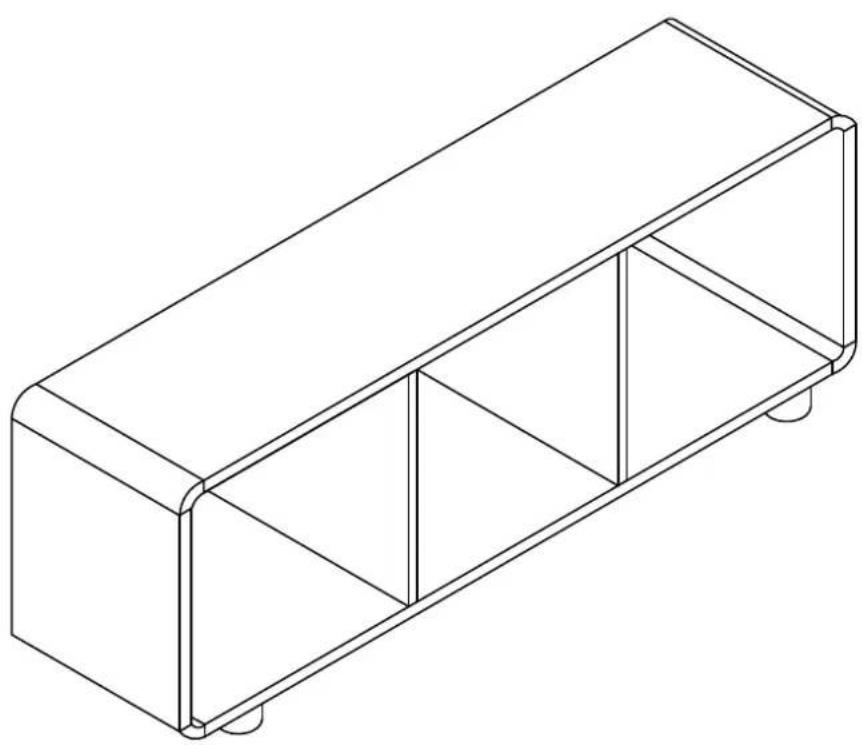
Large Record Storage Console CF1137
natural_image
Isometric line drawing of a rectangular metal enclosure with supports and legs (no text or symbols)PART LIST
A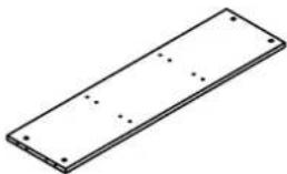 | B | C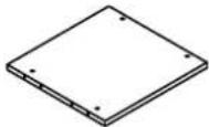 | D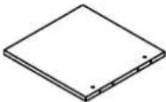 | E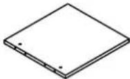 |
| Top Panel1 PC | Left Panel1 PC | Right Panel1 PC | Left Partition Panel1 PC | Right Partition Panel1 PC |
F | G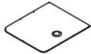 | H | I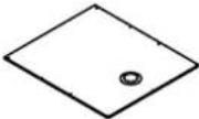 | J |
| Bottom Panel1 PC | Left Back Panel1 PC | Right Back Panel1 PC | Middle Back Panel1 PC | Corner4 PCS |
| K[w6WT] | L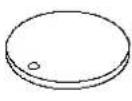 | |||
| Leg5 PCS | Cover3 PCS | |||
HARDWARE LIST
#1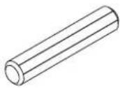 ∅10*50mm ∅10*50mm | #2 1-1/2"*∅1/4 1/2"*∅1/4 1-1/2"*∅1/4 1/2"*∅1/4 | #3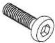 | #4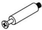 | #5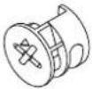 |
| Wood Dowel24 PCS(Extra 1) | Long Bolt4 PCS (Extra 1) | Short Bolt4 PCS (Extra 1) | Cam Bolt20 PCS(Extra 1) | Cam Lock20 PCS (Extra 1) |
#6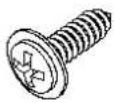 | #7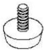 | #8 | #9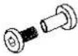 | #10 ∅M4 ∅M4 |
| Screw28 PCS (Extra 1) | Adjustable Leveler5 PCS | Cover12 PCS | Binding Post3 SETS (Extra 1) | Allen Wrench1 PC |
#11 ∅M2 ∅M2 | #12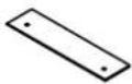 | |||
| Small Allen Wrench1 PC | Metal Plate2 PCS | |||
ADDITIONAL TOOLS (Not Provided)
Note: It is not recommended to use power tools during assembly.

Phillips Head Screwdriver
Note: Wood dowels are intended for alignment. Additional clearance between wood dowel and pre-drilled hole is intentional for ease of assembly.
Step 1. Insert cam bolts (parts #4) into pre-drilled holes of top panel and corners (parts A & J) using phillips head screwdriver.
Note : Do not over tighten cam bolts. Stop tightening once threads on cam bolts are no longer visible.

text_image
longer visible. #4 #4 J x 4 #4 #4 A #4 #4 #4 x 20 #4Step 2. Attach corners (part J) to panels (parts A & F) using wood dowels (part #1), cam locks (part #5) and phillips head screwdriver.
Note : Cam locks must rotate a full 180°. See pictured insert.
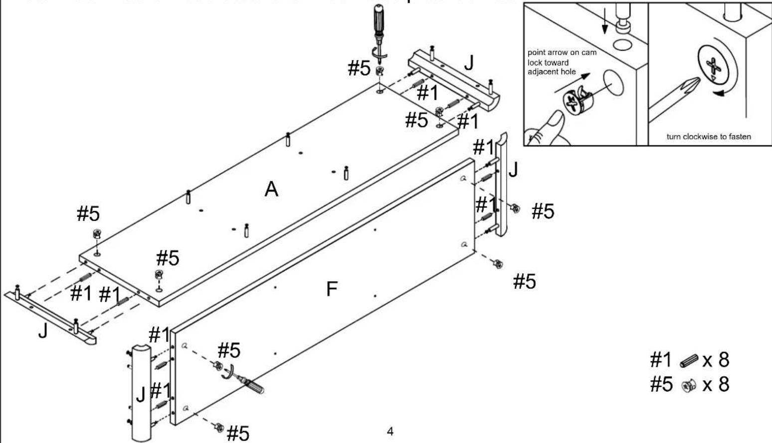
text_image
#5 #1 #5 #1 #1 #5 #1 #1 #5 #1 #1 #5 A F #5 #1 #1 #1 #1 #1 #1 #5 #1 x 8 #5 x 8 4 point arrow on cam lock toward adjacent hole turn clockwise to fastenStep 3. Attach covers (part L) to back panels (parts G, H & I) using binding posts (part #9) and small allen wrench (part #11).
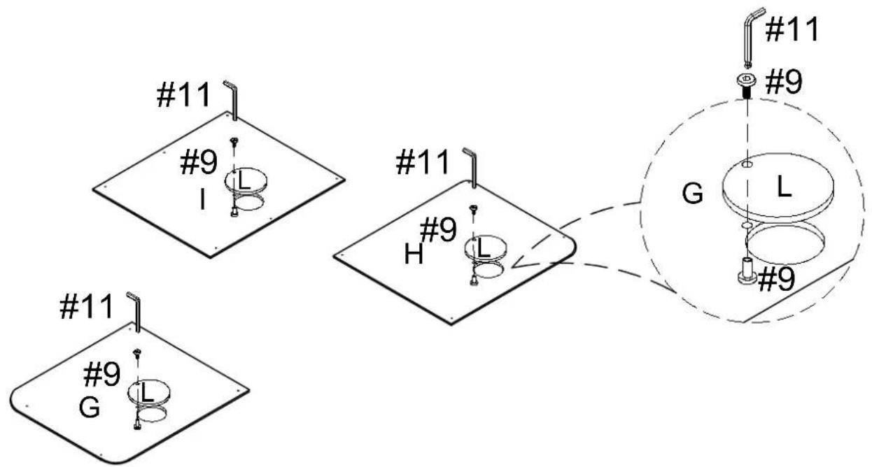
text_image
#11 #9 I #11 H #9 G #9 #11 #9 G L #99 x 3
11 \ x 1
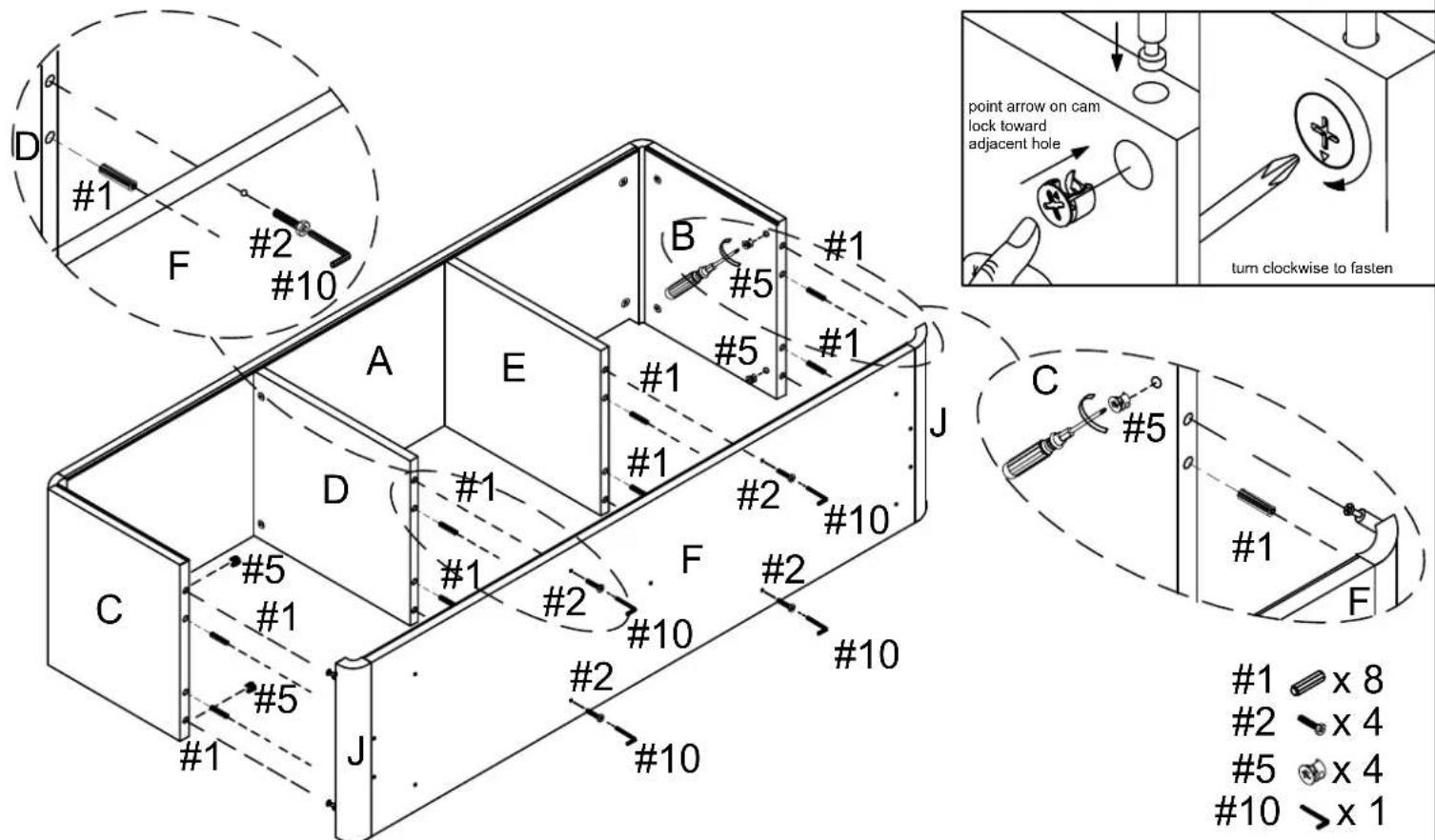
Step 4. Attach panels (parts B, C, D & E) to top panel (part A) using wood dowels (part #1), cam locks (part #5) and phillips head screwdriver.
Note : Cam locks must rotate a full 180°. See pictured insert.

text_image
#1 #5 #1 #1 #1 #1 #5 #5 #1 #5 B #1 #5 #1 #5 A E #1 #1 #1 #5 #1 #5 D C #1 #5 #5 #5 #1 #5 5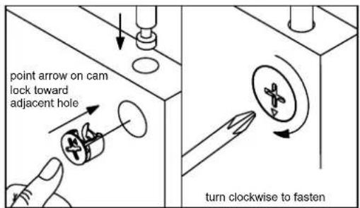
text_image
point arrow on cam lock toward adjacent hole turn clockwise to fasten1 ≡ x 8
5 x 8
Step 5. Attach panels (parts F & J) to assembled unit (parts B, C, D, & E) using wood dowels (part #1), cam locks (part #5), long bolts (part #2) and allen wrench (part #10).
Note : Cam locks must rotate a full 180°. See pictured insert.
text_image
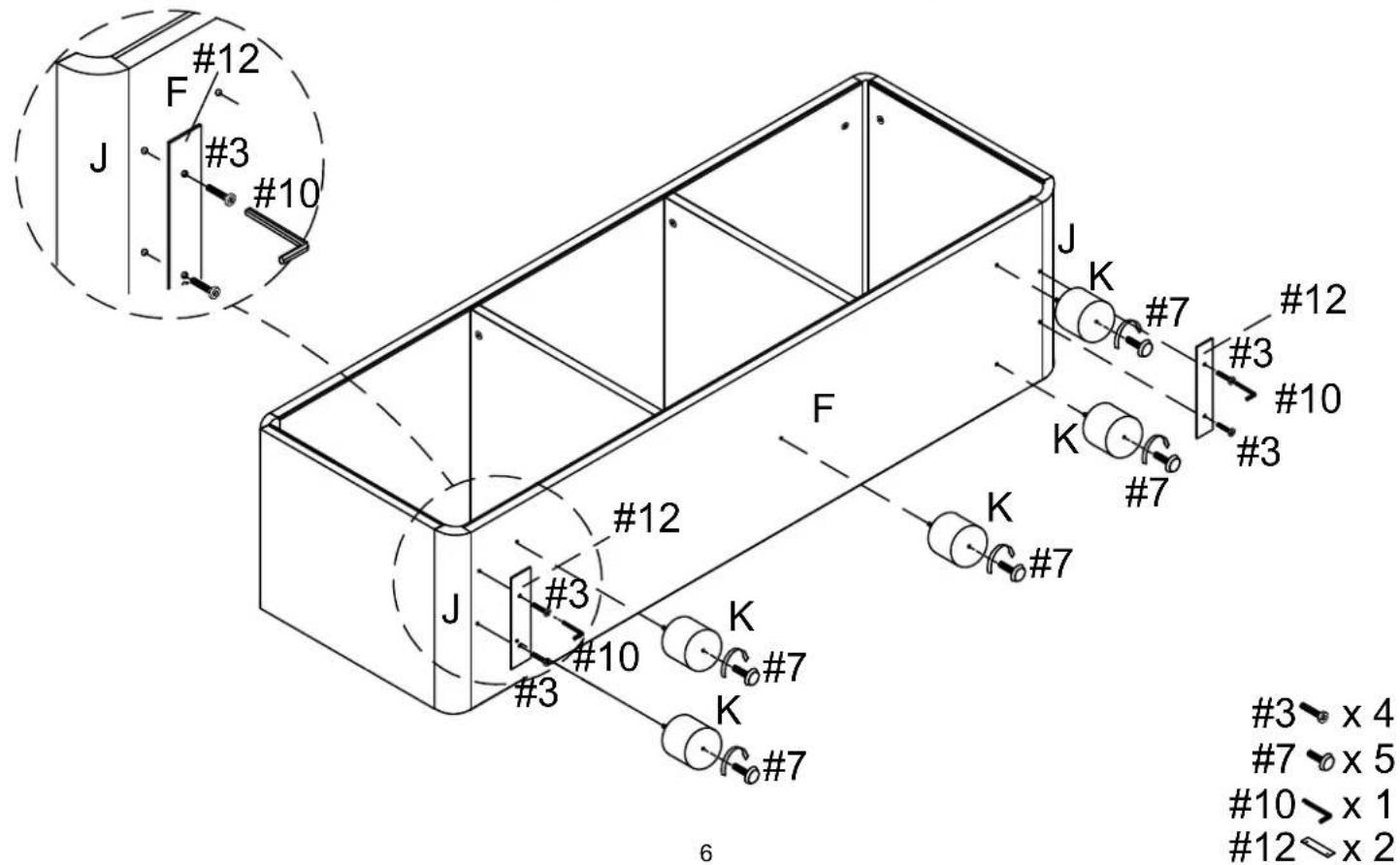
D #1 F #2 #10 A E B #5 #1 #5 #1 J point arrow on cam lock toward adjacent hole turn clockwise to fasten C #5 #1 F #2 #10 #1 #5 #10 #2 #10 #1 #5 #10 #1 x 8 #2 x 4 #5 x 4 #10 >x 1Step 6. Attach metal plates (part #12) to bottom panel (part F) using short bolts (part #3) and allen wrench (part #10). Attach legs (part K) to bottom panel (part F). Attach adjustable levelers (part #7) to legs (part K).
text_image
#12 F #3 #10 J #12 K #7 #12 #3 #10 #3 #12 F #3 #10 K #7 K #7 #3 × 4 #7 × 5 #10 × 1 #12 × 2 6Step 7. Attach back panels (parts G, H & I) to assembled unit (parts A, B, C, D, E & F) using screws (part #6) and phillips head screwdriver.

text_image
using screws (part #6) and phillips head screwdriver. #6 #6 H I G A E B D F C H #6 x 28Step 8. Attach covers (part #8) to the hole of cam locks (part #5).
