
Teagan KF33040BR - Kettle Crosley - Free user manual and instructions
Find the device manual for free Teagan KF33040BR Crosley in PDF.


| Product Type | Electric Kettle |
| Brand | Crosley |
| Model | Teagan KF33040BR |
| Capacity | 1.7 Liters |
| Power | 1500 Watts |
| Voltage | 120V, 60 Hz |
| Dimensions (W x D x H) | 8.5 x 6.5 x 9.8 inches |
| Weight | 2.4 lbs |
| Material | Stainless steel with retro plastic accents |
| Color | Brushed Red (BR) |
| Heating Element | Concealed stainless steel |
| Base | 360° swivel cordless base |
| Auto Shut-Off | Yes, when water reaches boiling |
| Boil-Dry Protection | Yes |
| Water Level Window | Yes, with markings |
| Lid | Flip-lock lid for easy filling |
| Spout | Gooseneck design for precise pouring |
| Handle | Ergonomic, cool-touch handle |
| Indicator Light | Power-on light |
| Cleaning and Care | Wipe exterior with damp cloth; decalcify with vinegar or citric acid periodically |
| Safety Features | Auto shut-off, boil-dry protection, overheat protection |
| Spare Parts Availability | Replacement base, lid, and filters available from manufacturer |
| Warranty | 1-year limited warranty |
Frequently Asked Questions - Teagan KF33040BR Crosley
User questions about Teagan KF33040BR Crosley
0 question about this device. Answer the ones you know or ask your own.
Ask a new question about this device
Download the instructions for your Kettle in PDF format for free! Find your manual Teagan KF33040BR - Crosley and take your electronic device back in hand. On this page are published all the documents necessary for the use of your device. Teagan KF33040BR by Crosley.
USER MANUAL Teagan KF33040BR Crosley
natural_image
Line drawing of a modern multi-level cabinet with four legs and one front panel (no text or symbols)PART LIST
| A |  | B | 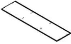 | C | 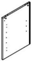 | D | 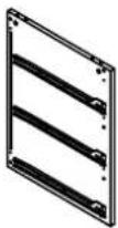 | E |  |
| Top Panel1 PC | Bottom Panel1 PC | Left Panel1 PC | Right Panel1 PC | Left Center Panel1 PC | |||||
| F |  | G | 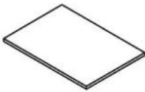 | H | I J |  |  | |  |
| Right CenterPanel1 PC | AdjustableShelf2 PCS | Top Front Rail1 PC | Drawer Front Rail2 PCS | Back Rail2 PCS | |||||
| K | [M N] |  | 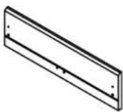 | 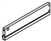 | O |  | |||
| Left Door1 PC | Right Door1 PC | Drawer FrontPanel3 PCS | Left Drawer Panel3 PCS | Right DrawerPanel3 PCS | |||||
| P |  | Q |  | R |  | S |  | T | 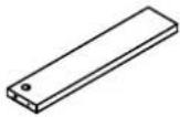 |
| Drawer BackPanel3 PCS | Drawer BottomPanel3 PCS | Right Back Panel1 PC | Left Back Panel2 PCS | Drawer Support3 PCS | |||||
HARDWARE LIST
| #1 | #2 #3 #4 #5 ∅1/4" x L2" ∅1/4" x ∅1/4" x L2" ∅1/4" x |  L19/32" ∅5/32" x L1 1/2" ∅1/8" x L5/8" L19/32" ∅5/32" x L1 1/2" ∅1/8" x L5/8" |  |  |  | |
| Screw8 PCS (Extra 1) | Bolt4 PCS (Extra 1) | Long Screw15 PCS (Extra 1) | Short Screw40 PCS (Extra 2) | Cam Lock29 PCS (Extra 2) | ||
| #6 | #7 #8 #9 # | 10 ∅8 x L25mm ∅8 x L25mm |  7/8" 2/8" 7/8" 2/8" | 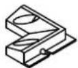 | ||
| Cam Bolt29 PCS (Extra 2) | Wood Dowel40 PCS (Extra 2) | Big Hinge2 PCS | Small Hinge2 PCS | Back Bracket4 PCS | ||
| #11 | #12 #13 | 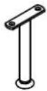 | #14 5/32" 5/32" | #15 | ||
| Shelf Support8 PCS | Side Leg4 PCS | Center Leg2 PCS | Allen Wrench1 PC | Safety Strap Kit1 SET | ||
ADDITIONAL TOOLS (Not provided)
Note: It is not recommended to use power tools during assembly.

Phillips Head Screwdriver
Note: Wood dowels are intended for alignment. Additional clearance between wood dowel and pre-drilled hole is intentional for ease of assembly.
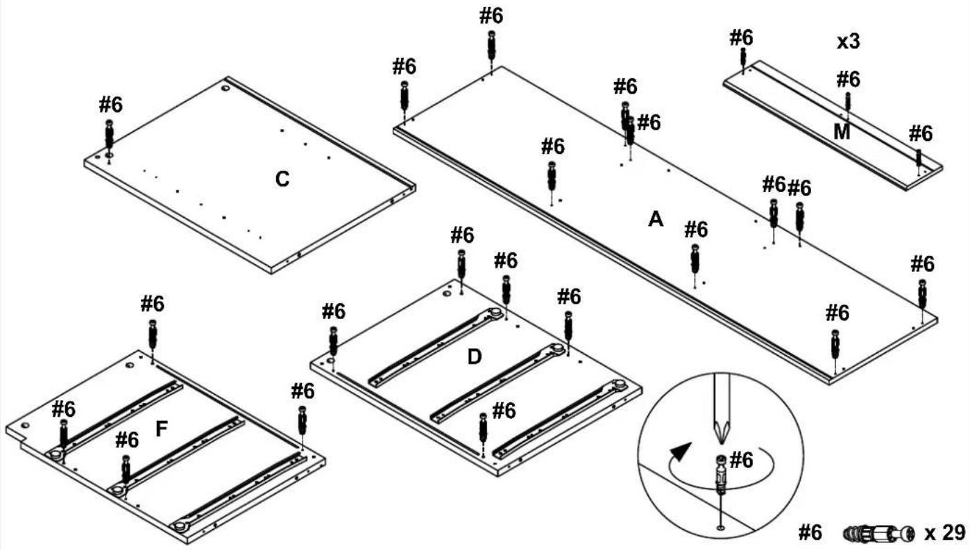
Step 1. Attach cam bolts (part #6) to panels (parts A, C, D, F & M) using phillips head screwdriver.
Note: Do not overtighten cam bolts. Stop tightening once threads on cam bolt are no longer visible.
Step 2. Attach legs (parts #12 & #13) to bottom panel (part B) using bolts (part #2), short screws (part #4), allen wrench (part #14) and phillips head screwdriver.

Step 3. Attach drawer panels (parts N & O) to drawer front panel (part M) using wood dowels (part #7) and cam locks (part #5). Slide drawer bottom panel (part Q) into grooves of assembled unit (parts M, N & O). Attach drawer support (part T) to drawer front panel (part M) using wood dowel (part #7) and cam lock (part #5). Attach drawer back panel (part P) to assembled unit (parts N, O, Q & T) using wood dowel (part #7), long screws (part #3) and phillips head screwdriver. Repeat for remaining drawers.

NOTE: Cam locks must rotate a full 180°. See pictured insert.
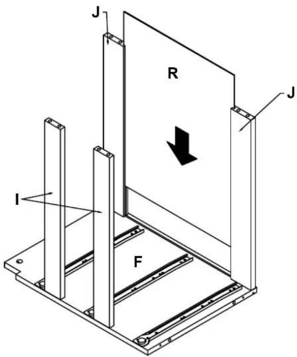
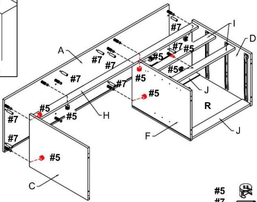
Step 4. Attach rails (parts I & J) to right center panel (part F) using wood dowels (part #7) and cam locks (part #5).

NOTE: Cam locks must rotate a full 180°. See pictured insert.

5
7


x 4
x 4
Step 5. Insert right back panel (part R) into grooves of assembled unit (parts F & J).
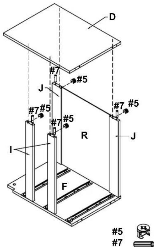
Step 6. Attach right panel (part D) to assembled unit (parts I & J) using wood dowels (part #7) and cam locks (part #5).
NOTE: Cam locks must rotate a full 180°. See pictured insert.

Step 7. Attach top front rail (part H) to assembled unit (parts D & F) and left panel (part C) using wood dowels (part #7) and cam locks (part #5).
NOTE: Cam locks must rotate a full 180°. See pictured insert.

5
7


x2
x 2
Step 8. Attach top panel (part A) to assembled unit (parts C, D, F & H) using wood dowels (part #7) and cam locks (part #5).
NOTE: Cam locks must rotate a full 180°. See pictured insert.

5
7


x 8
x8
Step 9. Attach left center panel (part E) to top panel (part A) using wood dowels (part #7) and cam locks (part #5).
NOTE: Cam locks must rotate a full 180°. See pictured insert.

Step 10. Carefully turn unit upside-down. Insert left back panels (part S) into grooves of assembled unit (parts A, C, E & F).

Step 11. Attach bottom panel (part B) to assembled unit (parts C, D, E & F) using wood dowels (part #7), screws (part #1) and allen wrench (part #14).
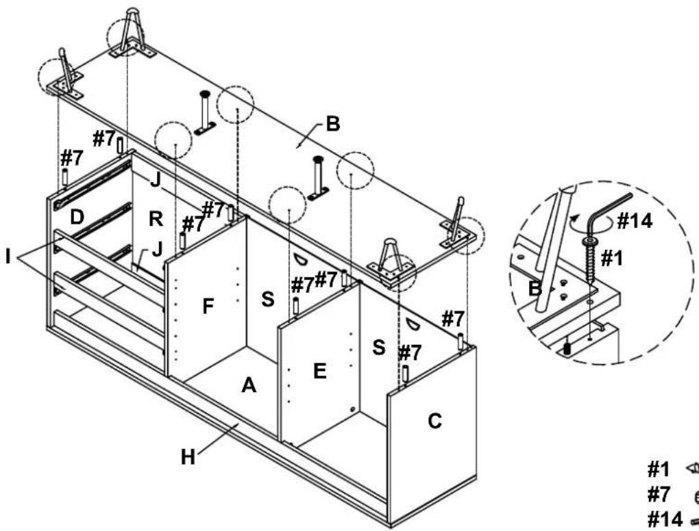
1 x 8
7 x 8
14 x 1
Step 12. Carefully turn unit upright. Secure back brackets (part #10) at the corner of left back panels (part S) using short screws (part #4) and phillips head screwdriver.

4 x 8
10 x 4
Step 13. Place shelf supports (part #11) into desired position and slide adjustable shelves (part G) into place.

11 x 8
Step 14. Attach big hinges (part #8) to left door (part K) and small hinges (part #9) to right door (part L) using short screws (part #4) and phillips head screwdriver. Attach doors (parts K & L) to panels (parts C & F) using short screws (part #4) and phillips head screwdriver.

Step 15. Slide assembled drawers into place.
Note: It is important to adjust levelers once fully assembled and upright. Extend adjustable leveler until it's firmly in contact with the floor. If relocating, adjust leveler as needed until it's firmly in contact with the floor in new location.
Important: Safety strap kit (part #15) must be installed to prevent tipping, damaged and/or injury.

| #15 | A | B | C | D | E |
 |  |  ∅1/8" x L5/8" ∅1/8" x L5/8" |  ∅5/32" x L1 1/2" ∅5/32" x L1 1/2" |  | |
| Safety Strap Kit1 SET | Wall Anchor2 PCS | Washer4 PCS | Short Screw2 PCS | Long Screw2 PCS | Safety WallStrap2 PCS |
SAFETY WALL STRAP INSTALLATION
Note: It is highly recommended to install this safety strap kit to prevent tipping, damage and/or injury.
- Insert short screw (C) through washer (B) and safety wall strap (E) and attach to top panel (part A) using phillips head screwdriver.
- Drill a 11/32" hole where you want to secure the unit. The drilled hole will be at the same height as the hole in top panel (part A) where the safety wall strap (E) is attached. Tap wall anchor (A) into the hole.
- Insert long screw (D) through washer (B) and safety wall strap (E) into wall anchor (A) using phillips head screwdriver.
Note: This item is not intended for clothing storage use.

ADJUST YOUR DOORS TO MAKE THE GAPS MORE EVEN (OPTIONAL).
Adjust the gap between door panel and side panel

Loosen the screw indicated a little, adjust the hinge to right position (see step 2a & 2b), then tighten the screw.
STEP 2a MOVE DOOR IN

Push the hinge back a little.
STEP 2b MOVE DOOR OUT

Pull the hinge forward a little.
STEP 3
To adjust the gap between two door

Loosen or tighten the screw indicated a little to adjust the gap between doors panels (see step 3a & step 3b)
STEP 3a MOVE DOOR RIGHT
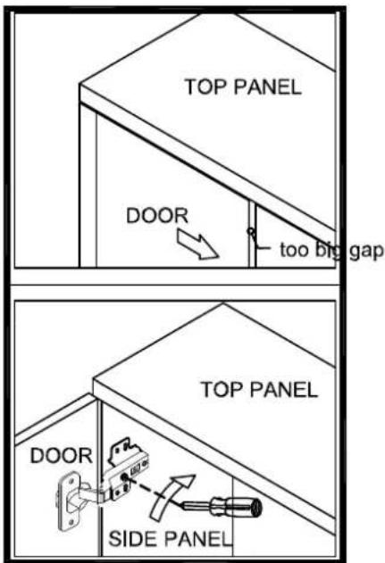
Turn the screw clockwise a little as shown to make the gap small.
STEP 3b MOVE DOOR LEFT

Turn the screw counterclockwise a little as shown to make the gap big.
Brand : Crosley
Model : Teagan KF33040BR
Category : Kettle