CM890D - Pregnant SoundTube - Free user manual and instructions
Find the device manual for free CM890D SoundTube in PDF.

User questions about CM890D SoundTube
0 question about this device. Answer the ones you know or ask your own.
Ask a new question about this device
Download the instructions for your Pregnant in PDF format for free! Find your manual CM890D - SoundTube and take your electronic device back in hand. On this page are published all the documents necessary for the use of your device. CM890D by SoundTube.
USER MANUAL CM890D SoundTube
Install Instructions For:
CM800d, CM890d and CM1001d speakers
text_image
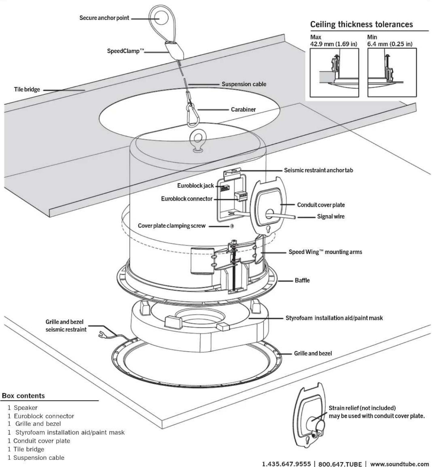
Secure anchor point SpeedClamp™ Tile bridge Suspension cable Carabiner Seismic restraint anchor tab Euroblock jack Euroblock connector Conduit cover plate Signal wire Cover plate clamping screw Speed Wing™ mounting arms Baffle Styrofoam installation aid/paint mask Grille and bezel seismic restraint Grille and bezel Box contents 1 Speaker 1 Euroblock connector 1 Grille and bezel 1 Styrofoam installation aid/paint mask 1 Conduit cover plate 1 Tile bridge 1 Suspension cable 1.435.647.9555 | 800.647.TUBE | www.soundtube.com Ceiling thickness tolerances Max 42.9 mm (1.69 in) Min 6.4 mm (0.25 in) Strain relief (not included) may be used with conduit cover plate.© 2008 SoundTube Entertainment, Inc. All rights reserved. PN INS-CMd Rev09.15.08
CM800d, CM890d, and CM1001d- UL listed 1480 & 2043

Warning
SoundTube speakers must be installed by a professional audio installer/contractor. For safety and for optimum audio performance, installer must follow all directions issued by SoundTube Entertainment.

Warning
Do not spec or install speaker near support beam, ventilation duct or other structure that may interfere with speaker function or dispersion.
natural_image
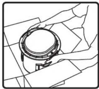
Line drawing of a mechanical component with hands operating it (no text or symbols)- Unpack speaker & set aside grille assembly.

natural_image
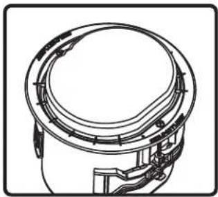
Technical line drawing of a cylindrical mechanical component with internal components (no text or symbols)- Keep Styrofoam installation aid/paint mask attached to speaker until speaker installation is complete.
natural_image
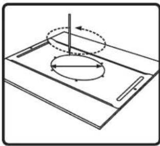
Pure technical diagram of a mechanical component with no text, numbers, or symbols- Use included tile bridge to mark cutout in tile.
natural_image
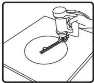
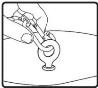
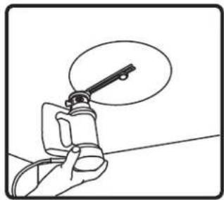
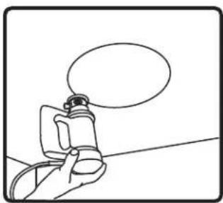
Line drawing of a hand using a tool to apply liquid onto a circular object on a flat surface (no text or symbols)- Use Rotozip or other tool to cut hole. Hole diameter 325.1 mm (12.80 in)
natural_image
Line drawing of a hand holding a circular mechanical component on a flat surface (no text or symbols)- Insert speaker into mounting hole on ground with installation aid in place. Tighten both bolts located on the baffle face to actuate the mounting wings. Firmly secure both sides – do not over-tighten. Replace assembled tile and speaker into tile grid.
natural_image
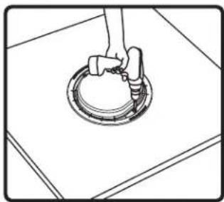
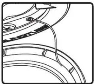
Line drawing of a hand holding a tool over a curved object (no text or symbols)- For added support attach eyelet end of suspension cable to the rear of speaker using the carabiner. Attach the other end of support cable to secure structure using speedclamp. If required, attach the seismic restraint system to the sheet-metal tab on the side of speaker (seismic restraint not included).

natural_image
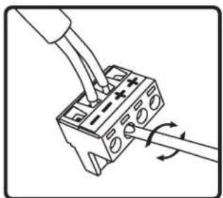
Diagram of a hand inserting a plug into a terminal block with directional arrows indicating rotation (no text or symbols)- Thread signal wire through conduit cover plate. Connect signal wire to 4-pin Euroblock plug. Tighten unused terminal screws. Use inside positive and negative inputs for either voice coil or distributed systems. For daisy chaining, use outside positive and negative terminals. Euroblock must be plugged in for daisy chain to function.

natural_image
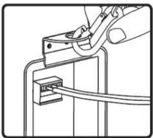
Diagram of a mechanical or electrical connector assembly with a cable inserted (no text or symbols visible)- Insert the Euroblock plug into the Euroblock jack on side panel of speaker and replace conduit cover plate. For UL-compliant installations strain relief (not supplied) may be inserted into hole in conduit cover plate.
natural_image
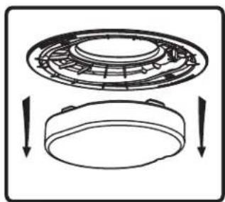
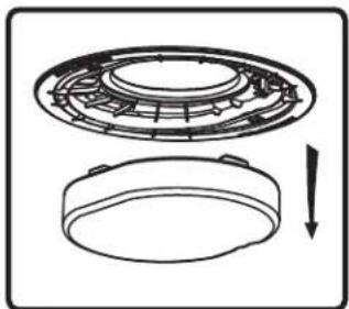
Diagram showing a circular mechanical component with internal structure and two downward arrows indicating motion or assembly (no text or symbols)- If you are not painting the ceiling, remove & discard the paint mask.
text_image
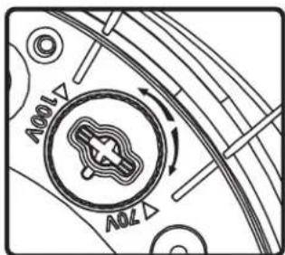
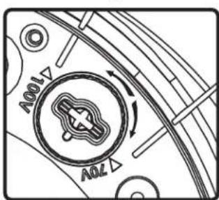
100V 70V- Select the tap position by adjusting rotary switch to desired high impedance value or voice coil bypass mode. Switch is preset to maximum tap setting in 70.7 V mode.
natural_image
Pure mechanical component diagram without any text, numbers, or symbols- Attach grille & bezel seismic restraint to baffle with provided screw.

natural_image
Pure geometric pattern with intersecting lines forming a diamond shape and a central oval (no text or symbols)- Attach grille – position the grille over the baffle and allow magnets to attract grille into place. Be sure grille is properly centered over baffle.

natural_image
Line drawing of hands holding a circular object over a patterned background (no text or symbols)- Unpack speaker & set aside grille assembly.
natural_image
Technical line drawing of a mechanical component with internal channels and mounting brackets (no text or symbols)- Keep Styrofoam installation aid/paint mask attached to speaker until speaker installation is complete.

natural_image
Simple line drawing of a tilted rectangular object with a circular arrow indicating rotation or motion, no text or symbols present.- Use included tile bridge to mark cutout in sheetrock.
natural_image
Hand holding a tool with a magnified view of the tip (no text or symbols visible)- Use Rotozip or other tool to cut hole. Hole diameter 325.1 mm (12.80 in)
natural_image
Diagram of a hand inserting a plug into a terminal block with arrows indicating rotation (no text or symbols)- Thread signal wire through conduit cover plate. Connect signal wire to 4-pin Euroblock plug. Tighten unused terminal screws. Use inside positive and negative inputs for either voice coil or distributed systems. For daisy chaining, use outside positive and negative terminals. Euroblock must be plugged in for daisy chain to function.
natural_image
Pure electrical circuit lines without any symbols- Insert the Euroblock plug into the Euroblock jack on side panel of speaker and replace conduit cover plate. For UL-compliant installations strain relief (not supplied) may be inserted into hole in conduit cover plate.
natural_image
Line drawing of a hand using a power tool to adjust or install an RJ45 connector (no text or symbols present)- If seismic restraint is required, attach the suspension cabel to sheet-metal tab on the side speaker.

natural_image
Simple line drawing of a hand holding a circular object above a wall (no text or symbols)- Insert speaker into mounting hole with installation aid in place. Tighten both bolts located on the baffle face to actuate the mounting wings. Firmly secure both sides – do not over-tighten.

natural_image
Diagram showing two views of a circular mechanical component with internal structure, no text or symbols present- If you are not painting the ceiling, remove & discard the paint mask.

text_image
100V 70V- Select the tap position by adjusting rotary switch to desired high impedance value or voice coil bypass mode. Switch is preset to maximum tap setting in 70.7 V mode.
natural_image
Pure mechanical component diagram without any text, numbers, or symbols- Attach grille & bezel seismic restraint to baffle with provided screw.
natural_image
Simple 3D diagram of a rectangular block with a small circular feature on top (no text or symbols)- Attach grille – position the grille over the baffle and allow magnets to attract grille into place. Be sure grille is properly centered over baffle.

natural_image
Isometric line drawing of a circular component mounted on a rectangular base plate (no text or symbols)- Nail or screw bracket to joists. Secure cover plate and conduit away from hole in bracket.

natural_image
Simple 3D geometric shape with a rectangular top and a diagonal line segment (no text or symbols)- Complete Finish work.
natural_image
Simple line drawing of a hand holding a small object with a speech bubble above (no text or symbols)- Use Rotozip or other tool to cut hole.

natural_image
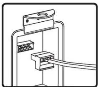
Diagram of a hand using a tool to connect two electrical connectors with rotating arrows (no text or symbols)- Thread signal wire through conduit cover plate. Connect signal wire to 4-pin Euro-block plug. Tighten unused terminal screws. Use inside positive and negative inputs for either voice coil or distributed systems. For daisy chaining, use outside positive and negative terminals. Euroblock must be plugged in for daisy chain to function.

natural_image
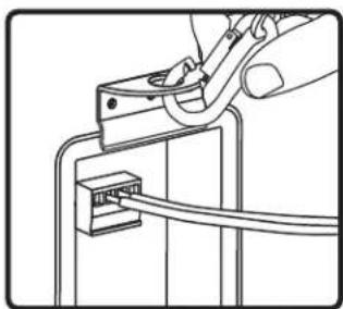
Diagram of a mechanical or electrical connector assembly with a cable inserted (no text or symbols visible)- Insert the Euroblock plug into the Euroblock jack on side panel of speaker and replace conduit cover plate. For UL-compliant installations strain relief (not supplied) may be inserted into hole in condit cover plate.
natural_image
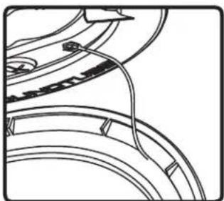
Line drawing of a hand using a power tool to adjust or install an RJ45 connector (no text or symbols present)- If seismic restraint is required, attach the suspension cabel to sheet-metal tab on the side speaker.

natural_image
Simple line drawing of a hand holding a circular object above a wall (no text or symbols)- Insert speaker into mounting hole with installation aid in place. Tighten both bolts located on the baffle face to actuate the mounting wings. Firmly secure both sides – do not over-tighten.
natural_image
Technical line drawing of a mechanical component with a circular housing and a separate circular base, showing internal structure and a downward arrow (no text or symbols)- If not painting the ceiling, remove & discard the paint mask.
- If painting the ceiling after the speaker is installed, leave the paint mask in place until paint is dry.
text_image
70V 100V- Select the tap position by adjusting rotary switch to desired high impedance value or voice coil bypass mode. Switch is preset to maximum tap setting in 70.7 V mode.

natural_image
Pure mechanical component diagram without any text, numbers, or symbols- Attach grille & bezel seismic restraint to baffle with provided screw.

natural_image
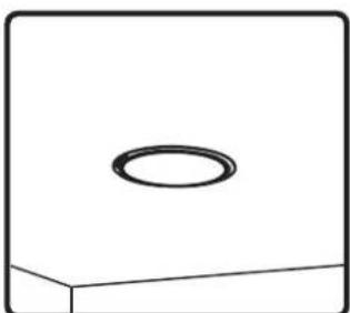
Simple line drawing of a rectangular block with a circular top and a horizontal base (no text or symbols)- Attach grille – position the grille over the baffle and allow magnets to attract grille into place. Be sure grille is properly centered over baffle.