WEB-10TX800 - NAS AIRLIVE - Free user manual and instructions
Find the device manual for free WEB-10TX800 AIRLIVE in PDF.

User questions about WEB-10TX800 AIRLIVE
0 question about this device. Answer the ones you know or ask your own.
Ask a new question about this device
Download the instructions for your NAS in PDF format for free! Find your manual WEB-10TX800 - AIRLIVE and take your electronic device back in hand. On this page are published all the documents necessary for the use of your device. WEB-10TX800 by AIRLIVE.
USER MANUAL WEB-10TX800 AIRLIVE
natural_image
Blue stylized icon of a lowercase 'a' with a dot above it, no text or symbols present.airlive®
Revision history
| Date | Version | Description |
| Dec 19 2024 | V 2.0 | The second edition |
Contents
1 Foreword....6
1.1 Target Audience....6
1.2 Manual Convention....6
2 Web Page Login....6
2.1 Log in the Network Management Client....6
2.2 Constitution of Client Interface 7
2.3 Navigation Bar on Web Interface 7
3 Status....10
3.1 System Information....10
3.2 Statistics ...... 11
3.3 MAC Address Table....12
3.4 Reboot....13
4 Network....14
4.1 IP Address....14
4.2 DNS 14
5 Port....16
5.1 Port Setting 16
5.2 Link Aggregation....17
5.2.1 Group....18
5.2.2 Port Setting....20
5.2.3 LACP 21
5.3 EEE 24
5.4 Jumbo Frame....25
5.5 Port Security 25
5.6 Protected Port 26
5.7 Storm Control....26
5.8 Mirroring....28
6 VLAN 29
6.1 VLAN 30
6.1.1 Create VALN....30
6.1.2 VLAN Configuration....32
6.1.3 Membership....32
6.1.4 Port Setting....33
7 MAC Address Table....35
7.1 Static Address....36
7.2 Filtering Address 36
8 Spanning Tree....37
8.1 Property 38
8.2 Port Setting....39
9 ERPS....41
9.1 Property 41
9.2 ERPS Instance 42
10 Loopback....44
11 Discovery....45
11.1 LLDP 46
11.2 Port Setting....47
11.3 MED Network Policy....49
11.4 MED Port Setting....50
11.5 Packet View 52
11.6 Local Information....52
11.7 Neighbor....53
11.8 Statistics....54
12 Multicast....54
12.1 General....54
12.1.1 Property 54
12.1.2 Group Address 55
12.1.3 Router Port 56
12.2 IGMP Snooping....56
12.2.1 Property 57
13 Security 58
13.1 Management Access....58
13.1.1 Management Service....58
13.2 DHCP Snooping 59
13.2.1 Property 60
13.2.2 IMPV Binding 61
14 QoS 62
14.1 General....64
14.1.1 Property....64
14.1.2 Queue Scheduling....65
14.1.3 CoS Mapping....66
This manual is prepared for the installers and system administrators who are responsible for network installation, configuration and maintenance. It assumes that the user has understood all network communication and management protocols, as well as the technical terms, theoretical principles, practical skills, and expertise of devices, protocols and interfaces related to networking. Work experience in Graphical User Interface (GUI), Command-line Interface, Simple Network Management Protocol (SNMP) and Web Explorer is also required.
**This manual has been made with the images and layout of the WEB-2TX1602 Switch. The layout of other models could differ slightly.**
1.2 Manual Convention
The following approaches should prevail.
| GUI Convention | Description |
| Interpretation | Describe operations and add necessary information. |
 Caution Caution | Remind the user of cautions as improper operations will result in data loss or equipment damage. |
2 Web Page Login
2.1 Log in the Network Management Client
Type in the default switch address: http://192.168.2.1 and press "Enter".
Description:
Browser standards: superior to IE 9.0, Chrome 23.0 and Firefox 20.0
Keep the IP network segment of PC consistent with that of switch but differentiate the IP address as you log in. Set PC's IP address of 192.168.2.x and the subnet mask of 255.255.255.0 for the first login (1 < x ≤ 254).
A login window appears as follows. Type in the default username of "admin" and the password of "admin". Click the "Log in" to see the switch system.

text_image
Login Username: Password: Login2.2 Constitution of Client Interface
The typical operation interface of Web network management system is as follows.
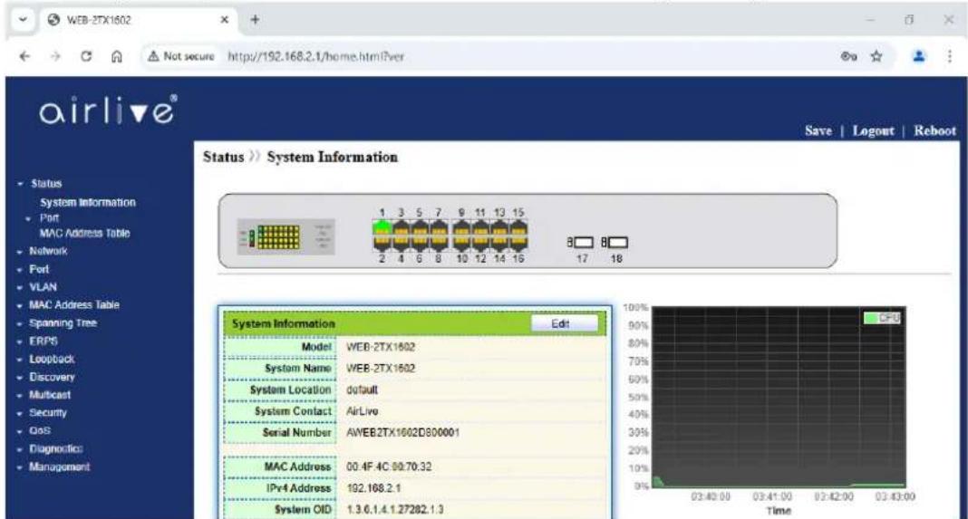
text_image
WEB-2TX1602 Not secure http://192.168.2.1/home.html?ver airlive® Status >> System Information Save | Logout | Reboot System Information Edit Model WEB-2TX1602 System Name WEB-2TX1602 System Location default System Contact AirLive Serial Number AWEB2TX1602D800001 MAC Address 00.4F.4C 00:70:32 IPr4 Address 192.168.2.1 System OID 1.3.6.1.4.1.27282.1.3 CPB Time2.3 Navigation Bar on Web Interface
Menu items such as Status, Network, Port, VLAN, MAC Address Table, Spanning Tree, ERPS, Multicast, Security, QoS, Diagnostics and Management are available on the web
network management client. Each item contains submenus. Navigation bar is detailed as follows:
| Menu Items | Submenus | Secondary Submenus | Description |
| Status | System Information | Display the port state and product info | |
| Port | Statistics | Display the detailed port statistics | |
| MAC Address Table | Display the MAC address table of the current device | ||
| Network | IP Address | Configure and view the management IP address | |
| DNS | Configure and view the DNS and server setting | ||
| Port | Port Setting | Configure and view all ports | |
| Link Aggregation | Group | Configure and view the port & strategy balancing algorithms contained in LAG | |
| Port Setting | Configure and view the LAG | ||
| LACP | Check LACP system priority and port configuration | ||
| EEE | Configure and view the EEE state and information | ||
| Jumbo Frame | Configure and view the length of the max message forwarded by system | ||
| Port Security | Configure and view the rate limiting of port security, as well as port state | ||
| Protected Port | Configure and view the port isolation | ||
| Storm Control | Configure and view the port storm policing | ||
| Mirroring | Configure and view the port mirroring | ||
| VLAN | VLAN | Create VLAN | Configure and view the VLAN info of the device |
| VLAN Configuration | Configure and view the VLAN configuration of all ports | ||
| Membership | Configure and view the port info of VLANs | ||
| Port Setting | Configure and view the PVID and VLAN attributes of ports | ||
| MAC Address Table | Static Address | Configure and view the static MAC address tables of the device | |
| Filtering Address | Configure and view the MAC address tables to be filtered | ||
| Spanning Tree | Property | Configure and view the STP state and attributes | |
| Port Setting | Configure and view the port attributions of STP | ||
| ERPS | Property | Configure and view the ERPS global switch | |
| ERPS Instance | Configure and view the ERPS Instance | ||
| Loopback | Loopback Config | Configure and view the loopback configuration | |
| Discovery | LLDP | Property | Configure and view the attributes related to LLDP |
| Port Setting | Configure and view the transmitting & receiving state of LLDP at each port | ||
| MED Network Policy | Configure and view the MED network strategy table entry | ||
| MED Port Setting | Configure and view the MED state at each port | ||
| Packet View | Configure and view the detailed LLDP messages at each port | ||
| Local Information | Configure and view the LLDP and LLDP-MED state | ||
| Neighbor | Configure and view the LLDP neighbor info | ||
| Statistics | Configure and view the transmitting & receiving state of LLDP message at each port | ||
| Multicast | General | Property | Configure and view the function configuration |
| Group Address | Configure and view the relevant static multicast info | ||
| Router Port | Configure and view the multicast routed port info | ||
| IGMP Snooping | Property | Configure and view the switch, version, etc. | |
| Security | Management Access | Management Service | Configure and view the service management mode and relevant attributes |
| DHCP Snooping | Property | Configure and view the switch and state | |
| IMPV Binding | Configure and view the binding tables of IP, MAC, Port and VLAN | ||
| QoS | General | Property | Configure and view the QoS switch and state |
| Queue Scheduling | Configure and view the algorithm of queue scheduling | ||
| CoS Mapping | Configure and view the priority and local queue mapping table | ||
| DSCP Mapping | Configure and view the priority and local queue mapping table | ||
| Rate Limit | Ingress/Egress Port | Configure and view the configuration of port rate limiting | |
| Diagnostics | Ping | Network diagnostics by Ping | |
| Copper Test | Electrical interface link diagnostics by VCT | ||
| Management | User Account | Configure and view the user info | |
| Firmware | Manual Upgrade | Update software | |
| Configuration | Manual Upgrade | Update configuration files | |
| Save Configuration | Save the configuration files supporting device running | ||
| SNMP | Community | Configure and view the SNMP Community | |
| Trap Event | Configure and view the SNMP Trap switch and state | ||
| Notification | Configure and view the SNMP Notification server state |
3 Status
3.1 System Information
According to the switch connected, web network management panel directly displays the port and product info, incl.: number of ports, port states, product info, device states, function on-off states, etc.
Instructions:
- Click the "Status > System Information" in the navigation bar as follows:
Status >> System Information
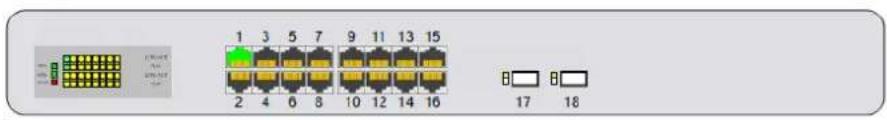
text_image
1 2 3 4 5 6 7 8 9 10 11 12 13 14 15 16 17 18
text_image
System Information Edit Model WEB-2TX1602 System Name WEB-2TX1602 System Location default System Contact AirLive Serial Number A/WEB2TX1002D800001 MAC Address 00:4F:4C:00:70:32 IPv4 Address 192.168.2.1 System UID 1.3.6.1.4.1.27282.1.3 System Uptime 6 day. 19 hr. 43 min and 43 sec Current Time 2024-01-08 03:43:28 UTC+8 Firmware Version 1.1.1.23 Firmware Date Jul 04 2024 - 10:24:54 HTTP Enabled SNMP Disabled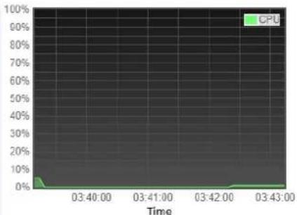
line
| Time | CPU | | ------- | ---- | | 03:40:00 | 5% | | 03:41:00 | 0% | | 03:42:00 | 0% | | 03:43:00 | 0% |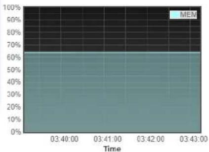
area
| Time | MEM (%) | |---|---| | 03:40:00 | 62 | | 03:41:00 | 62 | | 03:42:00 | 62 | | 03:43:00 | 62 |Description:
Mouseover a port to check the port No., type, rate and state. "Edit" the "System Name", "Location" and "Contact" in the product info. "Apply" and finish.
3.2 Statistics
Introduce the detailed flow statistics at a port and the info to be refreshed or cleared manually by users.
- Click the "Status > Port > Statistics" in the navigation bar as follows:

text_image
Port TE1 MIB Counter All Interface Etherlike RMON Refresh Rate None 5 sec 10 sec 30 sec
| Interface | |
| ifInOctets | 4206296095 |
| ifInUcastPkts | 475407066 |
| ifInNUcastPkts | 3310499630 |
| ifInDiscards | 0 |
| ifOutOctets | 2791189504412 |
| ifOutUcastPkts | 5087886513 |
| ifOutNUcastPkts | 3845755419 |
| ifOutDiscards | 0 |
| ifInMulticastPkts | 2116249609 |
| ifInBroadcastPkts | 1194250021 |
| ifOutMulticastPkts | 38145471202 |
| ifOutBroadcastPkts | 60022585 |
Description:
"Clear" the flow statistics at the current port and refresh the page.
3.3 MAC Address Table
View MAC address table information Instructions:
- Click the "Status > MAC Address Table" in the navigation bar as follows:
MAC Address Table
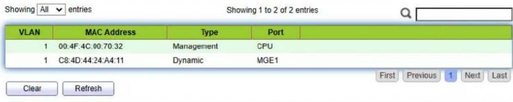
text_image
Showing All entries Showing 1 to 2 of 2 entries VLAN MAC Address Type Port 1 00:4F:4C:00:70:32 Management CPU 1 C8:4D:44:24:A4:11 Dynamic MGE1 Clear Refresh First Previous 1 Next LastInterface data are as follows.
| Query Items | Description |
| MAC | Destination MAC Address |
| VLAN | VLAN ID belonging to MAC address |
| Port | Message egress corresponding to MAC address |
| Type | Dynamic MAC Address refers to the entry which will age with the set aging time. Switches can add entries based on the learning mechanism of MAC address or manual creation.Static MAC address refers to the specified table which is manually configured and won’t age.Management MAC address refers to the address at the management port. |
3.4 Reboot
- Click the "Reboot" on the upper right as guided as follows.
Save | Logout | Reboot
Reboot the system and unsaved changes in the configuration will be lost. Do you want to continue?
OK
Cancel
4 Network
4.1 IP Address
Change the management IP address on web interface.
Instructions:
- Click the "Network > IP Address" in the navigation bar to discover IPv4 address of 192.168.2.1/24 by default as follows

text_image
Management VLAN VLAN 1 (note:make sure add changing vlan to corresponding port before change) IPv4 Address Address Type Static Dynamic IP Address 192.168.2.1 Subnet Mask 255.255.255.0 Default Gateway ApplyNote:
● make sure add changing vlan to corresponding port before change
4.2 DNS
DNS is short for Domain Name System to name computers and network services from units to domain hierarchies. A domain name consists of the dots separated by a series of words or abbreviations, each corresponding to a unique IP address. DNS is the server on the Internet that resolves domain names. Applicable to Internet and other TCP/IP networks, DNS name retrieves computers and services through user-friendly names. As one of the core Internet services, DNS is a distributed database that maps domain names and IP addresses mutually.
Instructions:
- Click on the "Network > DNS" in the navigation bar as follows.
DNS Configuration
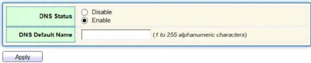
text_image
DNS Status Disable Enable DNS Default Name (1 to 255 alphanumeric characters) ApplyDNS Server Configuration

text_image
Preference DNS Server 0 results found. Add DeleteInterface data are as follows.
| Configuration Items | Description |
| DNS State | DNS switch |
| DNS Default Name | Enter the DNS default name |
- "Add" to configure DNS server.
Add DNS Server
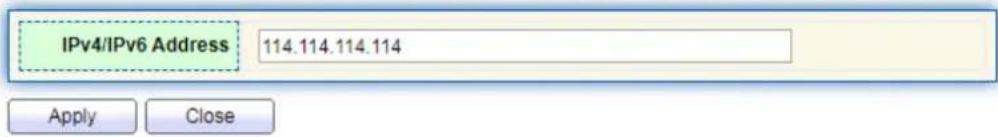
text_image
IPv4/IPv6 Address 114.114.114.114 Apply Close- "Apply" and finish as follows.
DNS Server Configuration
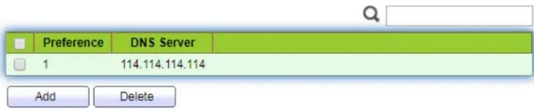
text_image
Preference DNS Server 1 114.114.114.114 Add Delete5 Port
5.1 Port Setting
Interfaces should be identified so that users can inquire and configure Ethernet interfaces as they want.
Instructions:
- Click the "Port > Port Setting" in the navigation bar:
Port Setting Table
| Entry | Port | Type | Description | State | Link Status | Speed | Duplex | Flow Control | |
| 1 | TE1 | 10G Copper | Enabled | Up | Auto (1000M) | Auto (Full) | Disabled (Off) | ||
| 2 | TE2 | 10G Copper | Enabled | Down | Auto | Auto | Disabled | ||
| 3 | TE3 | 10G Copper | Enabled | Down | Auto | Auto | Disabled | ||
| 4 | TE4 | 10G Copper | Enabled | Down | Auto | Auto | Disabled | ||
| 5 | TE5 | 10G Copper | Enabled | Down | Auto | Auto | Disabled | ||
| 6 | TE6 | 10G Copper | Enabled | Down | Auto | Auto | Disabled | ||
| 7 | TE7 | 10G Copper | Enabled | Down | Auto | Auto | Disabled | ||
| 8 | TE8 | 10G Copper | Enabled | Down | Auto | Auto | Disabled |
- Select the port(s) to be configured, and "Edit" as follows:
Edit Port Setting
| Port | TE2 | |
| Description | ||
| State | Enable | |
| Speed | Auto 100MAuto - 100M 1000MAuto - 1000M 2500MAuto - 2500M 5000MAuto - 5000M 10GAuto - 10000M | |
| Duplex | AutoFullHalf | |
| Flow Control | AutoEnableDisable | |
Interface data are as follows
| Configuration Items | Description |
| Port | Port list |
| Description | Port alias |
| State | Enable or disable port |
| Speed | Configurable auto negotiation. Interface rates including 100 Mbit/s and 1,000 Mbit/s and 2500 Mbit/s and 5000 Mbit/s and 10 Gbit/s are available to Ethernet electrical interfaces and are optional as required. |
| Duplex | Configurable auto negotiation with full or half duplexes. |
| Flow Control | After it is enabled on both local network and opposite network devices, the local one will notify the other to stop transmitting messages in the presence of network congestion. The opposite one will execute the command temporarily to ensure zero message loss.Disable-Disabled reception and transmission of PAUSE frame; Enable-Enabled reception and transmission of PAUSE frame; Auto negotiation-Negotiate PAUSE frame with opposite network devices automatically. |
5.2 Link Aggregation
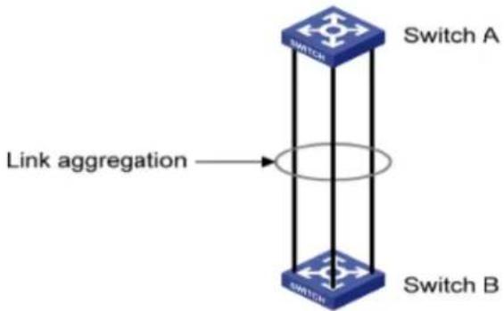
Link Aggregation broadens bandwidth and reliability by bundling a group of physical interfaces into a single logical interface.
LAG (Link Aggregation Group) is a logical link bundled by multiple Ethernet links (Eth-Trunk).
Ceaselessly expanding network size increases users' demands of link bandwidth and reliability. Traditionally, high-speed interface board or the compatible equipment is usually replaced to optimize bandwidth, which is expensive and inflexible.
Link Aggregation Technology bundles multiple physical interfaces into a single logical interface without upgrading hardware. Its backup mechanism not only improves reliability, but also shares the flow load on different physical links.
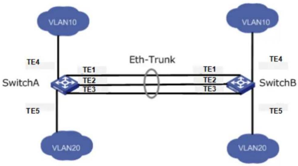
As shown below, Switch A is linked with Switch B through three Ethernet links which are bundled into an Eth-Trunk logical link. Its bandwidth equals to that of the three links in total, thus broadening the bandwidth. Meanwhile, these three links back up mutually to be more reliable.
flowchart
graph TD
    VLAN10["VI LAN10"] -->|TE4| SwitchA["SwitchA"]
    SwitchA -->|TE1| SwitchB["SwitchB"]
    SwitchA -->|TE2| SwitchA
    SwitchA -->|TE3| SwitchB
    SwitchB -->|TE1| VLAN10
    SwitchB -->|TE2| VLAN20["VI LAN20"]
    SwitchB -->|TE3| SwitchA
    SwitchA -->|TE5| VLAN20
    SwitchB -->|TE5| VLAN20
    SwitchA -->|TE4| VLAN10
    SwitchB -->|TE4| VLAN10
    SwitchA -->|TE5| VLAN20
    SwitchB -->|TE5| VLAN20
    SwitchA -->|TE4| SwitchB
    SwitchB -->|TE4| SwitchA
Link Aggregation can meet the following demands:
● Insufficient bandwidth of two switches connected with one link.
● Insufficient reliability of two switches connected with one link.
Link Aggregation can be divided into Manual Mode and LACP Mode in accordance with Link Aggregation Control Protocol (LACP) state.
In the first mode, Eth-Trunk establishment, member interface access should be added manually without LACP. It is also called the Load-sharing Mode because all links are involved in data forwarding and load sharing. In case any active link fails, LAG will average load with the remaining ones. This mode is preferred under the circumstance that two directly connected devices require a larger link bandwidth but has no access to LACP.
5.2.1 Group
Instructions for adding a Static Link Aggregation:
- Click the "Port > Link Aggregation > Group", select a load-balancing algorithm with a radio button. "Apply" and finish as follows:

text_image
Load Balance Algorithm ● MAC Address ○ IP-MAC Address
Link Aggregation Table

| LAG | Name | Type | Link Status | Active Member | Inactive Member | |
| ○ | LAG 1 | --- | --- | |||
| ○ | LAG 2 | --- | --- | |||
| ○ | LAG 3 | --- | --- | |||
| ○ | LAG 4 | --- | --- | |||
| ○ | LAG 5 | --- | --- | |||
| ○ | LAG 6 | --- | --- | |||
| ○ | LAG 7 | --- | --- | |||
| ○ | LAG 8 | --- | --- |
Edit
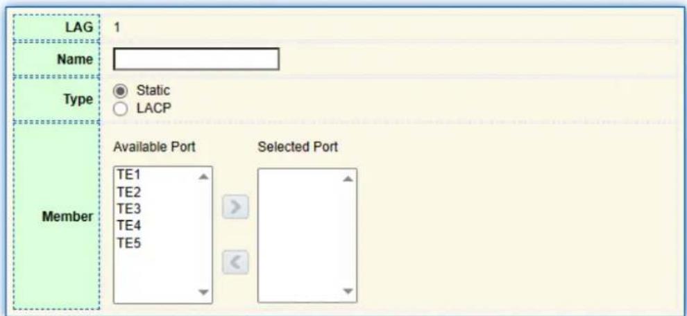
- Select one of 8 LAGs available, "Edit" the configuration page as follows:
Edit Link Aggregation Group
text_image
LAG 1 Name Static Type LACP Member Available Port TE1 TE2 TE3 TE4 TE5 Selected PortApply
Close
Interface data are as follows
| Configuration Items | Description |
| LAG | There are 8 LAGs numbering from 1 to 8. |
| Name | Description of LAG, which can be modified as needed. |
| Type | Select from the manual mode and the LACP mode. |
| Member | Up to 8 member ports are available in LAG. |
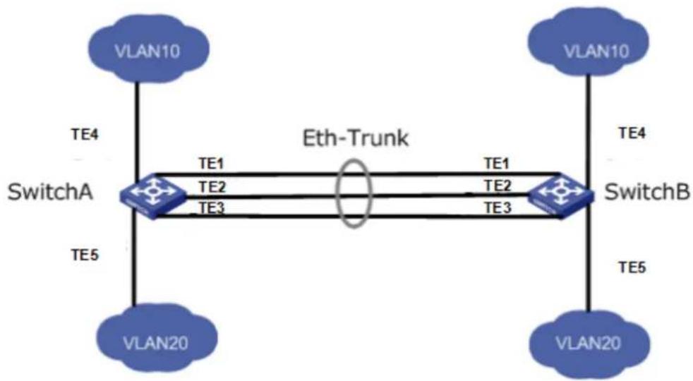
Illustration:
As shown below, Switch A and Switch B connect VLAN 10 and 20 via Ethernet respectively, with large data flow between them.
Both Switch A and B are expected to provide superior link bandwidth for VLAN communication. Meanwhile, there should be the redundancy for reliable data transmission and links.
Networking diagram LAG in manual mode
flowchart
graph TD
    A["VLAN10"] -->|TE4| B["SwitchA"]
    C["VLAN10"] -->|TE4| D["SwitchB"]
    E["VLAN20"] -->|TE5| B
    F["VLAN20"] -->|TE5| D
    B -->|TE1| G["Eth-Trunk"]
    B -->|TE2| G
    B -->|TE3| G
    D -->|TE1| G
    D -->|TE2| G
    D -->|TE3| G
Instructions:
- Create the ETH trunk interface in SwitchA and add a member interface to increase the link bandwidth. The configuration of SwitchB is like that of SwitchA. Click the "Port > Link Aggregation > Group", choose "LAG 1" and port TE1, 2 and 3 and move them to the selected ports on the right. "Apply" and finish as follows.
Link Aggregation Table
| LAG | Name | Type | Link Status | Active Member | Inactive Member | ||
| ○ | LAG 1 | Static | Up | TE1 | TE2-TE3 | ||
| ○ | LAG 2 | --- | --- | ||||
| ○ | LAG 3 | --- | --- |
5.2.2 Port Setting
Attribute configuration of aggregation group member port
- Click the "Port > Link Aggregation > Port Setting", to enter the attribute configuration interface of aggregation group member port as follows:
Port Setting Table

| LAG | Type | Description | State | Link Status | Speed | Duplex | Flow Control | |
| LAG 1 | Enabled | Down | Auto | Auto | Disabled | |||
| LAG 2 | Enabled | Down | Auto | Auto | Disabled | |||
| LAG 3 | Enabled | Down | Auto | Auto | Disabled | |||
| LAG 4 | Enabled | Down | Auto | Auto | Disabled | |||
| LAG 5 | Enabled | Down | Auto | Auto | Disabled | |||
| LAG 6 | Enabled | Down | Auto | Auto | Disabled | |||
| LAG 7 | Enabled | Down | Auto | Auto | Disabled | |||
| LAG 8 | Enabled | Down | Auto | Auto | Disabled |
Edit
5.2.3 LACP
LACP (Link Aggregation Control Protocol), based on IEEE 802.3ad Standard, dynamically aggregates and dis-aggregates links. It exchanges info with the opposite network devices through LACPDU (Link Aggregation Control Protocol Data Unit). After a port uses LACP, it will inform the opposite network device of system priority, system MAC, port priority and No., and operation Key by transmitting a LACPDU. The opposite device will compare such info with that saved by other ports after receiving it, thus reaching an agreement on port participation in or quitting from a dynamic aggregation.
Dynamic LACP aggregation is automatically created or deleted by system, that is, internal ports can be added or removed by themselves. Only the ports connected to a same device with the same rate, duplex, and basic configuration can be aggregated. Instructions for adding a dynamic link aggregation:
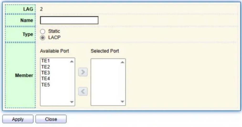
- Click the "Port > Link Aggregation > Group" in the navigation bar, select the LAG ID and LACP mode, "Edit" them as follows:
text_image
LAG Name Type Member 2 Static LACP Available Port TE1 TE2 TE3 TE4 TE5 Selected Port Apply Close- Click the "Port >Link Aggregation > LACP" in the navigation bar to configure the LACP attributes such as system priority, port priority and timeout method as follows:

text_image
System Priority 32768 (1 - 65535, default 32768) ApplyLACP Port Setting Table
| Entry | Port | Port Priority | Timeout | |
| 1 | TE1 | 1 | Long | |
| 2 | TE2 | 1 | Long | |
| 3 | TE3 | 1 | Long | |
| 4 | TE4 | 1 | Long | |
| 5 | TE5 | 1 | Long |
Interface data are as follows
| Configuration Items | Description |
| System Priority | LACP determines the active and passive modes between two devices subject to priority standard. |
| Port | Port list |
| Port Priority | LACP determines the dynamic LAG member mode subject to the port priority with a superior system. |
| Timeout | It decides the transmission frequency of LACP messages. |
Description:
Please make sure there is no member interface accessing the Eth-Trunk before changing its work pattern, otherwise it fails.
Work pattern of the local network devices should be consistent with that of the opposite network devices.
Illustration
Ethernet Switch A aggregates 3 ports from TE1 to TE3 to Switch B, in order to share the load by each member port.
The following configurations are exampled by means of dynamic aggregation.
flowchart
graph TD
    A["Switch A"] -->|Link aggregation| B["Switch B"]
    style A fill:#f9f,stroke:#333
    style B fill:#bbf,stroke:#333
Description:
The following is the configuration of Switch A only, which should stay the same with that of Switch B for port aggregation.
Instructions:
- Click the "Port > Link Aggregation > Group" in the navigation bar, "Edit" with LAG 2, select TE1-TE3 in LACP mode. "Apply" and finish as follows:
Edit Link Aggregation Group

text_image
LAG Name Type Member 2 Static LACP Available Port TE4 TE5 Selected Port TE1 TE2 TE3 Apply Close5.3 EEE
Port power will be turned down in case of zero or less flow Instructions:
- Click the "Port > EEE" in the navigation bar, select the port and "Edit" to enter the configuration interface as follows:
EEE Setting Table
| □ | Entry | Port | Type | State | |
| □ | 1 | TE1 | Copper | Disabled | |
| □ | 2 | TE2 | Copper | Disabled | |
| □ | 3 | TE3 | Copper | Disabled | |
| □ | 4 | TE4 | Copper | Disabled | |
| □ | 5 | TE5 | Copper | Disabled |
- Set the port enable tag and "Apply" to complete the configuration as follows:
EEE Setting Table
| Entry | Port | Type | State | |
| 1 | TE1 | Copper | Enabled | |
| 2 | TE2 | Copper | Enabled | |
| 3 | TE3 | Copper | Disabled | |
| 4 | TE4 | Copper | Disabled |
5.4 Jumbo Frame
Set the MTU (Maximum Transmission Unit) of the port Instructions:
- Click the "Port > Jumbo Frame" in the navigation bar, enter Jumbo Frame configuration interface as follows:

text_image
Jumbo Frame Enable 10000 Byte (1518 - 10000, default 1522) Apply5.5 Port Security
The port security feature records the Ethernet MAC address connected to the switch port through the MAC address table, and only one MAC address can communicate through this port. When packets sent by other MAC addresses pass through this port, port security features prevent it. Using port security features can prevent unauthorized devices from accessing the network and enhance security. In addition, port security features can also be used to prevent MAC address table from filling up due to MAC address flooding
Instructions:
- Click the "Port > Port Security" in the navigation bar, enter port security configuration interface as follows:

text_image
State Enable Rate Limit 100 Packet / Sec (1 - 600, default 100) Apply- Click the "Port > Port Security" in the navigation bar, select the port and "Edit" to enter the port level configuration interface as follows:
| Entry | Port | State | Address Limit | Total | Configured | Violate Number | Violate Action |
| 1 | TE1 | Disabled | 1 | 0 | 0 | 0 | Protect |
| 2 | TE2 | Disabled | 1 | 0 | 0 | 0 | Protect |
| 3 | TE3 | Disabled | 1 | 0 | 0 | 0 | Protect |
| 4 | TE4 | Disabled | 1 | 0 | 0 | 0 | Protect |
5.6 Protected Port
Messages of broadcast, multicast, etc. will flood at each port even though the flow needs no mutual communication sometimes. Under this circumstance, port isolation can separate the messages between two ports.
Instructions:
- Click the "Port > Protected Port" in the navigation bar, check the port(s) to be isolated, "Edit" to switch this function as follows:
Protected Port Table
| □ | Entry | Port | State | |
| □ | 1 | TE1 | Unprotected | |
| □ | 2 | TE2 | Unprotected | |
| □ | 3 | TE3 | Unprotected | |
| □ | 4 | TE4 | Unprotected |
Instructions for achieve port isolation:
- Click the "Port > Protected Port" in the navigation bar, check and "Edit" the TE1, 2 and 3 to be isolated. "Apply" and finish as follows:
Protected Port Table
| □ | Entry | Port | State | |
| □ | 1 | TE1 | Protected | |
| □ | 2 | TE2 | Protected | |
| □ | 3 | TE3 | Unprotected |
- TE1, 2 and 3 fail to communicate mutually like other non-isolated ports.
5.7 Storm Control
Storms generated via broadcast, unknown multicast and unicast messages are prevented as follows. These messages will be suppressed subject to packet rates respectively. The average rate of the messages received by monitoring interfaces will be compared with the max threshold configured during an inspection interval. Configured storm policing will be performed at this interface if the average rate exceeds the max threshold.
When a L2 Ethernet interface receives the broadcast, unknown multicast or unicast messages, the device will forward them to other L2 interfaces in a same VLAN (Virtual Local Area Network) if the egress interface cannot be recognized according to destination
MAC addresses. As a result, broadcast storm may occur to degrade device operation performance.
Three kinds of message flow can be controlled by storm policing characteristics to stay away from broadcast storms.
Instructions:
- Click the "Port > Storm Control" in the navigation bar to configure the attributes related to storm policing such as mode as follows:

text_image
Mode Packet / Sec Kbits / Sec IFG Exclude Include Apply- Select the appropriate port and "Edit" it by configuring the policing rates of broadcast, unknown multicast and unicast storms at each port.
Port Setting Table
| Entry | Port | State | Broadcast | Unknown Multicast | Unknown Unicast | Action | |||||
| State | Rate (Kbps) | State | Rate (Kbps) | State | Rate (Kbps) | ||||||
| 1 | TE1 | Disabled | Disabled | 10000 | Disabled | 10000 | Disabled | 10000 | Drop | ||
| 2 | TE2 | Disabled | Disabled | 10000 | Disabled | 10000 | Disabled | 10000 | Drop | ||
| 3 | TE3 | Disabled | Disabled | 10000 | Disabled | 10000 | Disabled | 10000 | Drop | ||
- Configure info such as storm switch and rate, "Apply" and finish as follows:
Edit Port Setting
| Port | TE1-TE2 | |
| State | Enable | |
| Enable | ||
| Broadcast | 10000 | Kbps (16 - 10000000, default 10000) |
| Unknown Multicast | Enable | |
| 10000 | Kbps (16 - 10000000, default 10000) | |
| Unknown Unicast | Enable | |
| 10000 | Kbps (16 - 10000000, default 10000) | |
| Action | Drop | |
| Shutdown | ||
5.8 Mirroring
Port Mirroring copies the message of a specified switch port to the destination port. The copied port is the Source Port, and the copying port is the Destination Port. Destination Port accesses to data inspection devices so that users can analyze the messages received to monitor network and troubleshoot as follows:

flowchart
graph TD
    A["Network"] --> B["Mirror Source Port"]
    B --> C["PC"]
    B --> D["Mirroring Destination Port"]
    D --> E["Data Monitoring Device"]
Instance
PC1 and PC2 access Switch A through interface TE1 and TE2 respectively.
Users intend to monitor the messages transmitted from PC2 to PC1.
Instructions:
- Click the "Port > Mirroring" in the navigation bar. 4 sets of flow mirroring rules can be configured as follows:
Mirroring Table
| Session ID | State | Monitor Port | Ingress Port | Egress Port | ||
| ◯ | 1 | Disabled | --- | --- | --- | |
| ◯ | 2 | Disabled | --- | --- | --- | |
| ◯ | 3 | Disabled | --- | --- | --- | |
| ◯ | 4 | Disabled | --- | --- | --- | |
| Edit | ||||||
Edit
"*" Allow the monitor port to send or receive normal packets
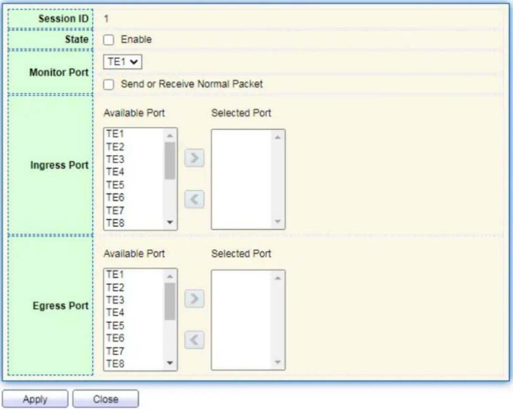
- Select one session and "Edit" it in the mirroring group configuration interface:
Edit Mirroring
text_image
Session ID 1 State Enable Monitor Port TE1 Send or Receive Normal Packet Ingress Port Available Port Selected Port TE1 TE2 TE3 TE4 TE5 TE6 TE7 TE8 Egress Port Available Port Selected Port TE1 TE2 TE3 TE4 TE5 TE6 TE7 TE8 Apply CloseInterface data are as follows
| Configuration Items | Description |
| Session ID | The switch has 4 session IDs by default. |
| State | The mirroring group can be enabled or not. |
| Monitor Port | Only one ordinary physical port can be selected, excluding lin aggregation port and source port. |
| Ingress Port | Any message received will be mirrored to the destination port. |
| Egress Port | Any message transmitted will be mirrored to the destination port. |
6 VLAN
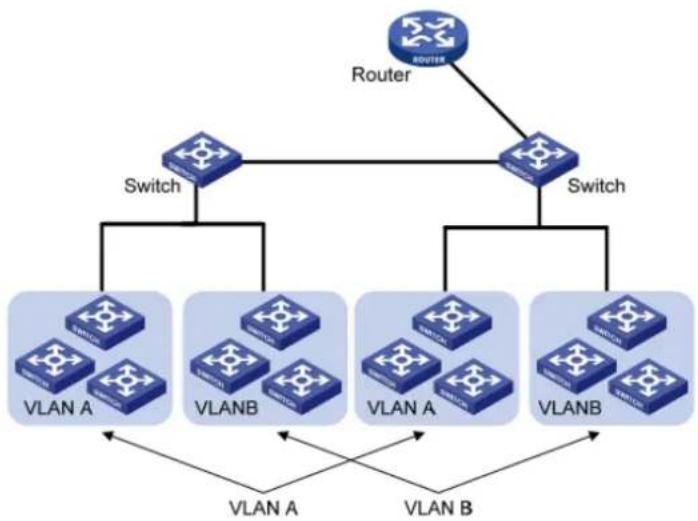
VLAN is formulated not restricted to physical locations, which means the hosts in a same VLAN can be placed at will. As shown below, each VLAN, as a broadcast domain, divides a physical LAN into logical LANs. Hosts can exchange messages by means of
traditional communication. For the hosts in different VLANs, the device such as router or L3 switch is a must.
flowchart
graph TD
    A["Router"] --> B["Switch"]
    A --> C["Switch"]
    B --> D["VLAN A"]
    B --> E["VLANB"]
    C --> F["VLAN A"]
    C --> G["VLANB"]
    D <--> H["VLAN A"]
    E <--> I["VLAN B"]
    F <--> J["VLAN B"]
    G <--> K["VLAN B"]
VLAN is superior to the traditional Ethernet in terms of:
- Broadcast domain coverage: the broadcast message in a LAN is limited in a VLAN to save the bandwidth and handle the network-related issues more efficiently.
● LAN security: VLAN hosts fail to communicate with each other since the messages are separated by the broadcast domain in the data link layer. They need a router or a Layer 3 switch for Layer 3 forwarding.
- Flexibility of creating a virtual working team: VLAN can create a virtual working team beyond the control of physical network. Users have access to the network without changing the configuration if their physical locations are moving within the scope. This management switch is compatible with VLAN types based on 802.1Q, protocols, MAC, and ports. For default configuration, 802.1Q VLAN mode should be adopted. Port VLAN is divided subject to a switch's interface No. Network administrator gives each switch interface a different PVID, namely a port default VLAN. If a data frame without a VLAN tag flows into a switch interface with a PVID, it will be marked with the same PVID, or it will get rid of an additional tag even though the interface has a PVID.
- The solution to a VLAN frame depends on the interface type, which eases member definition but re-configures VLAN in case of member mobility.
6.1 VLAN
6.1.1 Create VALN
Instructions for creating a new VLAN:
- Click the "VLAN > VLAN > Create VLAN" to select a name in the valid VLAN box, move
it to the VLAN creating box on the right. "Apply" and finish as follows:
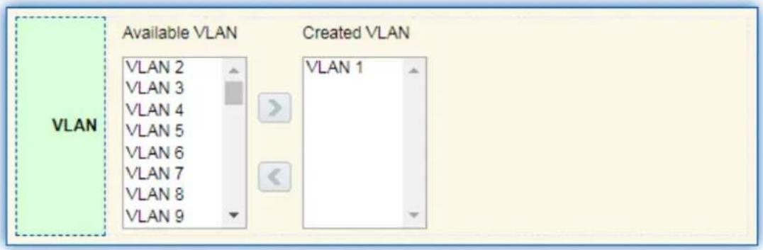
text_image
VLAN Available VLAN VLAN 2 VLAN 3 VLAN 4 VLAN 5 VLAN 6 VLAN 7 VLAN 8 VLAN 9 Created VLAN VLAN 1
VLAN Table

text_image
Showing All ▼ entries Showing 1 to 1 of 1 entries VLAN Name Type VLAN Interface State 1 default Default Disabled First Previous 1 Next Last Edit Delete- The VLAN created will be displayed in the VLAN Table. Users can "Edit" the VLAN as follows:
Edit VLAN Name
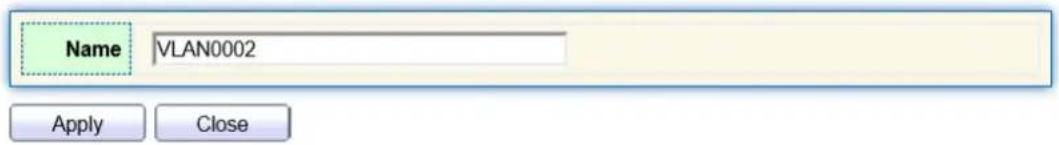
text_image
Name VLAN0002 Apply CloseInterface data are as follows.
| Configuration Items | Description |
| VLAN ID | It is required to select an ID ranging from 1 to 4,094. F example, 1-3,5,7 and 9. LAN 1 is the default, which won't be repeated in another new VLAN. |
| Name | It is optional to modify the VLAN description as required. |
6.1.2 VLAN Configuration
There are two methods. One is to add multiple ports under a single VLAN. The other is to add a port to multiple VLANs. They are configured according to different purposes. Instructions for the first method to add the current port to a specified VLAN
- Click the "VLAN > VLAN > VLAN Configuration" in the navigation bar, select the VLAN ID on the upper left, and then click the port info as follows:
VLAN Configuration Table

text_image
VLAN default Entry Port Mode Membership PVID Forbidden 1 TE1 Trunk ○ Excluded ○ Tagged ● Untagged ✓ □ 2 TE2 Trunk ○ Excluded ○ Tagged ● Untagged ✓ □ 3 TE3 Trunk ○ Excluded ○ Tagged ● Untagged ✓ □ 4 TE4 Trunk ○ Excluded ○ Tagged ● Untagged ✓ □ 5 TE5 Trunk ○ Excluded ○ Tagged ● Untagged ✓ □Interface data are as follows.
| Configuration Items | Description |
| VLAN | VLAN ID to be configured |
| Port | Port list |
| Mode | VLAN mode of port |
| Membership | Member roles at the VLAN port:Excluded: the port is out of this VLANTagged: the port is a tagged member of this VLANUntagged: the port is an untagged member of this VLAN |
| PVID | Whether this VLAN is the port PVID |
| Forbidden | Whether the VLAN message is forbidden to be forwarded at this port |
6.1.3 Membership
Instructions for the second method to add the current port to a specified VLAN
- Click the "VLAN > VLAN > Membership" in the navigation bar, select the port to be configured and "Edit" to configure its attributes:
| Entry | Port | Mode | Administrative VLAN | Operational VLAN | ||
| ○ | 1 | TE1 | Trunk | 1UP | 1UP | |
| ○ | 2 | TE2 | Trunk | 1UP | 1UP | |
| ○ | 3 | TE3 | Trunk | 1UP | 1UP |
Interface data are as follows.
| Configuration Items | Description |
| Port | Port list |
| Mode | VLAN mode of port |
| Membership | The port is the attribute of VLAN ID and VLAN:Forbidden: do not forward the VLAN messageExcluded: the port out of the VLANTagged: The Tagged member of the VLANUntagged: The Untagged member of the VLANPVID: whether the VLAN is the port PVLAN |
6.1.4 Port Setting
Trunk configuration. Connected with other switches, Trunk interfaces mainly connect trunk links to allow the VLAN frames to flow through. IEEE 802.1q is the encapsulation protocol of Trunk link and considers the formal standard for Virtual Bridged Local Area Networks. It changes the frame format of Ethernet by adding a 4-bit 802.1q Tag between the source MAC address field and the protocol field.
802.1q frame format
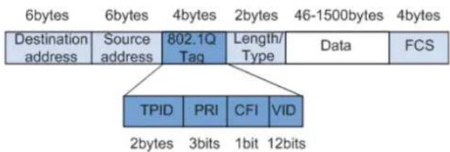
text_image
6bytes 6bytes 4bytes 2bytes 46-1500bytes 4bytes Destination address Source address 802.1Q Tag Length/ Type Data FCS TPID PRI CFI VID 2bytes 3bits 1bit 12bitsMeanings of 802.1q tag fields
| Field | Length | Name | Analysis |
| TPID | 2 bytes | Tag Protocol Identifier to describe the frame type | It refers to the 802.1q Tag frame when the value is 0x8,100, which will be discarded if relevant equipment fails to receive it. |
| PRI | 3 bits | Frame Priority | It ranges from 0 to 7, with the higher priority represented by larger number. Data frame with higher priority will be sent preferentially in case of switch congestion. |
| CFI | 1 bit | Canonical Format Indicator to reveal whether the MAC address is classical or not. | MAC address is classical when CFI is 0 and non-classical when CFI is 1. It promotes the compatibility between Ethernet and token ring. CFI will be 0 in the Ethernet. |
| VID | 12 bits | VLAN ID indicates the VLAN to which the frame belongs. | It ranges from 0 to 4,095, with 1 to 4,094 valid since 0 and 4,095 are the protocol retention values. |
Packets sent by each switch supporting 802.1q protocol contain a VLAN ID to indicate the VLAN to which the switch belongs. Therefore, Ethernet frames are divided into two types as follows in a VLAN switching network:
- Tagged frame: it refers to the frame adding a 4-bit 802.1q Tag.
- Untagged frame: it refers to the original frame without a 4-bit 802.1q Tag.
Connected with other switches, Trunk interfaces mainly connect trunk links to allow the VLAN frames to flow through.
Instructions for trunk interface configuration:
- Click the "VLAN > VLAN > Port Setting" in the navigation bar, select the port and "Edit" it to configure the attributes:
Port Setting Table
| Entry | Port | Mode | PVID | Accept Frame Type | Ingress Filtering | Uplink | TPID | ||
| 1 | TE1 | Trunk | 1 | All | Enabled | Disabled | 0x8100 | ||
| 2 | TE2 | Trunk | 1 | All | Enabled | Disabled | 0x8100 | ||
| 3 | TE3 | Trunk | 1 | All | Enabled | Disabled | 0x8100 | ||
| 4 | TE4 | Trunk | 1 | All | Enabled | Disabled | 0x8100 | ||
| 5 | TE5 | Trunk | 1 | All | Enabled | Disabled | 0x8100 |
Interface data are as follows.
| Configuration Items | Description |
| Port | Port No. to be configured |
| Mode | VLAN mode of portHybrid: port in this mode serves as the member of Tagged and Untagged ports of VLANsAccess: port in this mode serves as the only member of VLANTrunk: port in this mode serves as the only Untagge member of PVID and the Tagged member of VLANsTunnel: Port Q-in-Q VLAN |
| PVID | Port native VLAN |
| Accept Frame Type | Message types received by portsAll: all messagesTag Only: only Tagged messages will be receivedUntag Only: only Untagged messages will be received |
| Ingress Filtering | A switch to decide to filter VLAN messages excluded at the port |
| Uplink | Whether in uplink mode or not |
| TPID | Identification No. of VLAN Tag |
7 MAC Address Table
Ethernet switches are mainly innovated to forward according to the purposes in the data link layer. That is, MAC address will transmit the messages to corresponding ports according to the purposes. MAC address forwarding table is a L2 table illustrating MAC addresses and forwarding ports, which is the basis of fast forwarding of L2 messages.
MAC address forwarding table contains following data:
- Destination MAC Address
- VLAN ID belonging to port
● Forwarding ingress No. of this device
There are two message forwarding types according to MAC address table info:
- Unicast mode: the switch directly transmits the messages from the table's egress when MAC address forwarding table contains corresponding entries with the destination MAC address.
- Broadcast mode: When the switch receives the messages with the destination address full of F-bits, or there is no entry corresponding to the MAC destination address in the forwarding table, the switch will forward the messages to all ports excluding the receiving port in this way.
7.1 Static Address
Static table is manually configured by users and distributed to each interface board, which won't age.
Instructions:
- Click the "MAC Address Table > Static Address" as follows:
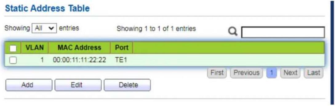
text_image
Static Address Table Showing All entries Showing 1 to 1 of 1 entries VLAN MAC Address Port 1 00:00:11:11:22:22 TE1 Add Edit Delete First Previous 1 Next LastInterface data are as follows.
| Configuration Items | Description |
| MAC | Required. Enter the new MAC address e.g.: HH:HH:HH:HH:HH:HH |
| VLAN | Required. Specify the VLAN ID |
| Port | Required. Select the interface type and enter the interface nameDescription: it must be the member port of the configured VLANs. |
- Fill in corresponding configuration items.
- "Apply" and finish.
7.2 Filtering Address
The switch discards the matched data frame by configuration Instructions:
- Click the "MAC Address Table > Filtering Address" as follows:
Filtering Address Table
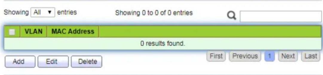
text_image
Showing All entries Showing 0 to 0 of 0 entries VLAN MAC Address 0 results found. Add Edit Delete First Previous 1 Next LastAdd Filtering Address

text_image
MAC Address VLAN (1 - 4094) Apply CloseInterface data are as follows.
| Configuration Items | Description |
| MAC Address | MAC address to be filtered |
| VLAN | VLAN of MAC address |
8 Spanning Tree
Redundant links are often used for link backup and network reliability in the Ethernet switching network. However, such links will generate loops on the switching network, leading to broadcast storm, unstable MAC address list and other faults, thus worsening users' communication quality, or even interrupting the communication. As a result, STP (Spanning Tree Protocol) appears.
Same with the development of other protocols, from the original STP defined in IEEE 802.1D, to RSTP (Rapid Spanning Tree Protocol) defined in IEEE 802.1W and to MSTP (Multiple Spanning Tree Protocol) defined in IEEE 802.1S, STP keeps upgrading.
MSTP is compatible with RSTP and STP while RSTP is compatible with STP. The contrast among these 3 protocols is shown in the table.
The contrast among 3 protocols
| STP | Characteristic | Application |
| STP | A tree rid of loops as the solution to broadcast storms and redundant backups. It converges slowly. | All VLANs can be shared without discrimination in user or business flow. |
| RSTP | A tree rid of loops as the solution to broadcast storms and redundant backups. It converges rapidly. | |
| MSTP | A tree rid of loops as the solution to broadcast storms and redundant backups. It converges rapidly. Spanning trees balance the load among VLANs. Flow of different VLANs will beforwarded subject to paths. | Distinguish the user and business flow for load sharing. Different VLANs forward the flow through separate spanning trees. |
After STP is deployed, the following objectives can be achieved by calculating the loops with topology:
- Loop elimination: eliminate possible communication loops by blocking redundant links.
- Link backups: activate redundant links to restore network connectivity if the active path fails.
8.1 Property
Configure STP global parameters. In specific network environment, STP parameters of some devices must be adjusted to achieve the best performance.
Instructions:
- Click the "Spanning Tree > Property" in the navigation bar as follows:
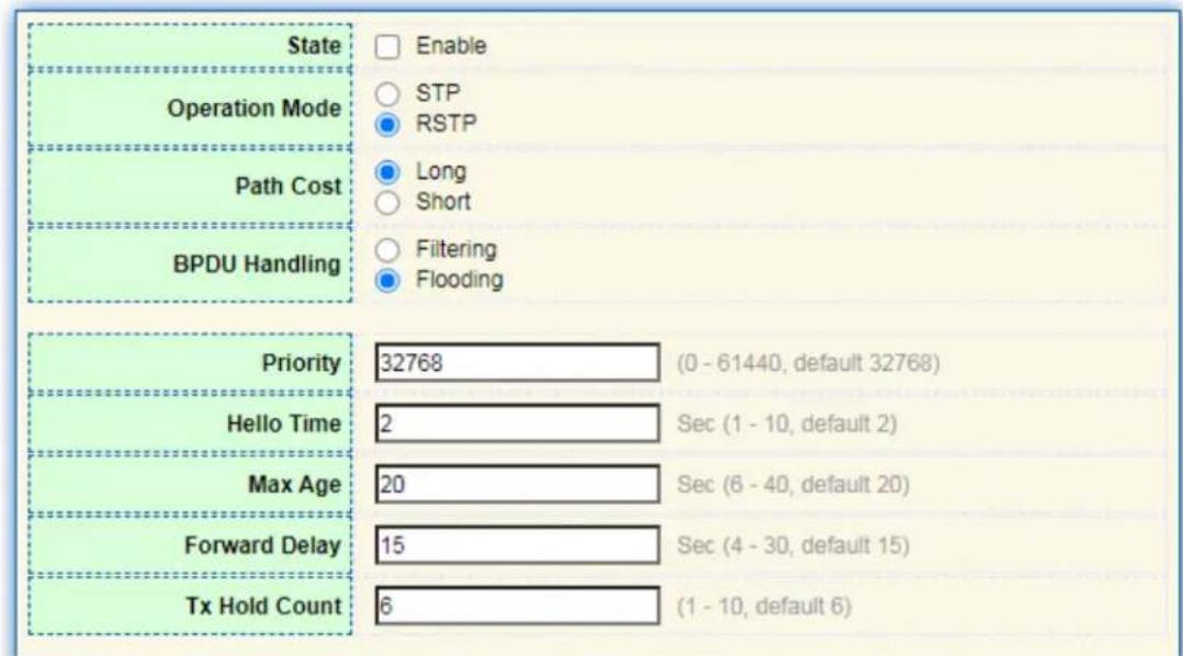
text_image
State Operation Mode Path Cost BPDU Handling Enable STP RSTP Long Short Filtering Flooding Priority 32768 (0 - 61440, default 32768) Hello Time 2 Sec (1 - 10, default 2) Max Age 20 Sec (6 - 40, default 20) Forward Delay 15 Sec (4 - 30, default 15) Tx Hold Count 6 (1 - 10, default 6)Interface data are as follows.
| Configuration Items | Description |
| State | It is checked by default to enable the spanning tree on behalf of switches. |
| Operation Mode | 3 modes are available, namely STP and RSTP. |
| Path Cost | In Long mode and Short mode |
| BPDU Handling | The method to handle the BPDU messages received by the device |
| Priority | Port priority |
| Hello Time | Intervals between Hello messages |
| Max Age | Max aging time |
| Forward Delay | Forward delay time |
| Tx Hold Count | Specify the Tx-hold-count used to limit the maximum numbers of packets transmission per second |
- Fill in corresponding configuration items.
- "Apply" and finish.
8.2 Port Setting
In specific network environment, STP parameters of some devices need to be adjusted for the best performance.
- Click the "Spanning Tree > Port Setting" in the navigation bar, select the port and "Edit" to configure its attributes:
Port Setting Table
| Entry | Fort | State | Path Cost | Priority | BPDU Filter | BPDU Guard | Operational Edge | Operational Point to Point | Port Role | Port State | Designated Bridge | Designated Port ID | Designated Cost |
| 1 | TE1 | Enabled | 2000 | 129 | Disabled | Disabled | Disabled | Disabled | Disabled | Disabled | 6:00:00:00:00:00 | 128-1 | 2000 |
| 2 | TE2 | Enabled | 2000 | 129 | Disabled | Disabled | Disabled | Disabled | Disabled | Forwarding | 6:00:00:00:00:00 | 128-2 | 2000 |
| 3 | TE3 | Enabled | 2000 | 129 | Disabled | Disabled | Disabled | Disabled | Disabled | Disabled | 6:00:00:00:00:00 | 128-3 | 2000 |
| 4 | TE4 | Enabled | 2000 | 129 | Disabled | Disabled | Disabled | Disabled | Disabled | Disabled | 6:00:00:00:00:00 | 128-4 | 2000 |
| 5 | TE5 | Enabled | 2000 | 129 | Disabled | Disabled | Disabled | Disabled | Disabled | Disabled | 6:00:00:00:00:00 | 128-5 | 2000 |
| 6 | TE6 | Enabled | 2000 | 129 | Disabled | Disabled | Disabled | Disabled | Disabled | Disabled | 6:00:00:00:00:00 | 128-6 | 2000 |
| 7 | TE7 | Enabled | 2000 | 129 | Disabled | Disabled | Disabled | Disabled | Disabled | Disabled | 6:00:00:00:00:00 | 128-7 | 2000 |

text_image
Port TE1 State Enable Path Cost 0 (0 - 200000000) (0 = Auto) Priority 128 Edge Port Auto Enable Disable BPDU Filter Enable BPDU Guard Enable Point-to-Point Auto Enable Disable Port State Disabled Designated Bridge 0-00:00:00:00:00:00 Designated Port ID 128-1 Designated Cost 2000 Operational Edge False Operational Point-to-Point False
Interface data are as follows.
| Configuration Items | Description |
| Port | The port No. to configure attributes |
| State | Enable STP or not |
| Path Cost | Enter the path cost value of the interface Use IEEE 802.1t Standard with the value ranging from 0 to 200,000,000 |
| Priority | Select the port priority with smaller value representing higher priority.Interface priority affects the role of the interface on the specific MSTI. On different MSTI, users can configure the priorities for a same interface. As a result, flow of different VLANs can be forwarded along physical links to achieve VLAN load sharing.Description: MSTP will recalculate the interface role and migrate its state when its priority changes. |
| Edge Port | Rather than another switch or network segment, the edge port should be connected directly to user terminals. It can quickly transit to the forward state since topology changes create no loops. Aedge port under configuration can be quickly transitioned to forward state by STP. To achieve this, it is recommended that Ethernet ports connected directly to user terminals should be configured as edge ports. |
| BPDU Filter | Enable BPDU Filter or not |
| BPDU Guard | Enable BPDU Guard or not. Unchecked by default. If BPDU Guard is enabled, the device will shut down the interfaces receiving BPDU and notify the NMS. Such interfaces can only be restored manually by network administrators. |
| Point-to-Point | Select enabled, shutdown, and auto modes.Auto mode: it indicates the connect state between the default auto inspection and point-to-point links.Enabled mode: it indicates the specific port is connected to the point-to-point links.Shutdown mode: it indicates the specific port fails to connect the point-to-point links. |
- Fill in corresponding configuration items.
- "Apply" and finish.
9 ERPS
ERPS (Ethernet Ring Protection Switching) is an Ethernet ring link layer technology with high reliability and stability. It can prevent broadcast storms caused by data loops when the Ethernet ring is complete, and can quickly restore communication paths between various nodes in the ring network in case of link failures in the Ethernet ring, with high convergence speed.
It is based on the ERPS ring and consists of several nodes. By blocking the RPL Owner port and controlling other ordinary ports, the port's state switches between Forwarding and Blocking, achieving the goal of eliminating the loop. Simultaneously utilizing mechanisms such as control VLAN, data VLAN, and MST protection instance to better implement the functionality of ERPS.
9.1 Property
Configure and view the opening and closing of the global ERPS function Instructions:
- Click on the "ERPS > Property" menu in the navigation bar to enter the function
configuration interface
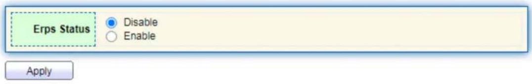
text_image
Erps Status Disable Enable Apply9.2 ERPS Instance
In an ERPS network, a ring can support multiple instances, each of which is a logical ring. Each instance has its own protocol channel, data channel, and owner node; Each instance serves as an independent protocol entity, maintaining its own state and data.
Instructions:
- Click the "ERPS > ERPS Instance" Enter the ERPS instance creation interface and click on the application to create an instance, as shown in the following figure:
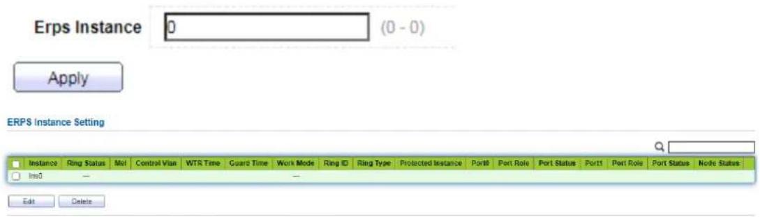
text_image
Erps Instance 0 (0 - 0) Apply ERPS Instance Setting Instance Ring Status Mol Control Vlan WTR Time Guard Time Work Mode Ring ID Ring Type Protected Instance Port8 Port Role Port Status Port1 Port Role Port Status Node Status Im0 — — Edit Delete- Select the instance and click the modify button to enter the instance configuration interface, as shown in the following figure:
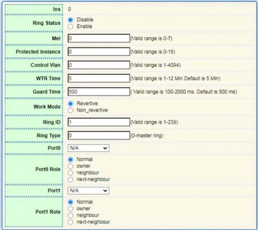
text_image
Ins Ring Status Mel Protected Instance Control Vlan WTR Time Guard Time Work Mode Ring ID Ring Type Port0 Port0 Role Port1 Port1 Role 0 Disable Enable 0 (Valid range is 0-7) 0 (Valid range is 0-15) 0 (Valid range is 1-4094) 5 (Valid range is 1-12 Min Default is 5 Min) 500 (Valid range is 100-2000 ms. Default is 500 ms) Revertive Non_revertive 1 (Valid range is 1-239) 0 (0-master ring) N/A Normal owner neighbour next-neighbour N/A Normal owner neighbour next-neighbour
| Configuration Items | Description |
| Ring Status | Disable or Enable |
| Mel | Message level selection 0-7 |
| Protected Instance | The VLAN that transmits ERPS protocol packets and dat packets must be mapped to the protection instance, so that the ERPS protocol can forward or block these packets according to its blocking principle. Otherwise, VLAN packets may generate a broadcast storm in the looped network resulting in network unavailability |
| Control VLAN | Control VLAN for transmitting ERPS protocol packets |
| WTR Time | In revertive mode, the RPL Owner port is released due to other link failures. When the fault recovers, wait for the WTR timer to time out and then block the RPL Owner port again |
| Guard Time | Start the Guard timer when the port detects link recovery, to prevent unnecessary network oscillation caused by residualR-APS messages caused by forwarding delay on the rin network |
| Work Mode | After the ERPS link returns to normal, it can be determined whether to re block the RPL owner port by setting the Revertive/Non Revertive mode of ERPS. |
| Ring ID | ERPS ring number |
| Ring Type | 0 is the main ring, only support main ring |
| Port0 | ERPS ring member port, used for the transmission of protocol and data packets on the ERPS ring |
| Port1 | ERPS ring member port, used for the transmission of protocol and data packets on the ERPS ring |
| Port Role | Normal、Owner、neighbour、next-neighbour |

Note :
- The ERPS function only satisfies a switching recovery delay of less than 20ms for the optical port
- Only support main ring.
10 Loopback
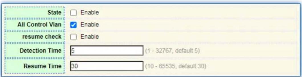
The configuration of the Loopback Detection function is as follows: global and port ring network enable and disable configurations are performed on the switch ports, which can be changed by the user
The time interval for ring network detection and the automatic recovery time period for ring network ports. By enabling global and port capabilities, the system can detect loop conditions in the network, thereby reducing the occurrence of loop storms. Supports two working modes: automatic detection and manual detection.
- Click on the "Loopback > Loopback Config" menu in the navigation bar to enter the function
text_image
State All Control Vlan resume check Detection Time 5 (1 - 32767, default 5) Resume Time 30 (10 - 65535, default 30)
| □ | Entry | Port | Mode | State | Port State | |
| □ | 1 | TE1 | Automation | Disabled | Forwarding | |
| □ | 2 | TE2 | Automation | Disabled | Forwarding | |
| □ | 3 | TE3 | Automation | Disabled | Forwarding | |
| □ | 4 | TE4 | Automation | Disabled | Forwarding |
| Configuration Items | Description |
| State | Loopback detection global switch, enable/disable |
| All Control Vlan | All VLANs on the port are enabled by default |
| resume check | Loopback recovery detection |
| Detection Time | Loopback detection cycle, default to 5 seconds |
| Resume Time | The cycle for automatic detection and recovery time of the loopback, default to 30 seconds |
| Port | Port list |
| Mode | Loopback detection working mode, automatic and manual, default to automatic |
| State | Port level loopback detection switch |
| Port State | The status of the port |
11 Discovery
LLDP (Link Layer Discovery Protocol) is defined in IEEE 802.1ab. It is a standard L2 discovery method which integrates the info such as management addresses, device and interface identifications of local network devices and transmits to the neighbor devices. After receiving the info, they will save it in form of standard MIB (Management Information Base) for NMS query and link communication judgment.
It can also integrate the info and transmit to its own remote devices. The info received by the local network device will be kept in the form of MIB. The following shows how it works.
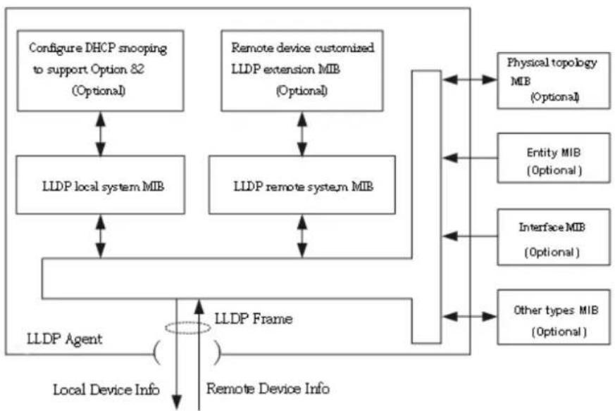
Block diagram of LLDP principles
flowchart
graph TD
    A["Configure DHCP snooping to support Option 82 (Optional)"] <--> B["LLDP local system MIB"]
    C["Remote device customized LLDP extension MIB (Optional)"] <--> D["LLDP remote system MIB"]
    E["LLDP Agent"] --> F["Local Device Info"]
    F --> G["LLDP Frame"]
    G --> H["Remote Device Info"]
    I["Physical topology MIB (Optional)"] <--> J["Entity MIB (Optional)"]
    K["Interface MIB (Optional)"] <--> L["Other types MIB (Optional)"]
    B <--> G
    D <--> G
    F <--> G
LLDP is realized based on:
- LLDP module updates its local system MIB, as well as the customized extension MIB, through the interaction between LLDP agent and MIBs of physical topology, entity, interface and other types.
● Encapsulate the info of local network device into LLDP frames and transmit to the remote device. - Receive the LLDP frame sent by the remote device to update LLDP remote system MIB and customized extension MIB.
● Master the info of remote device such as connection interface and MAC address through the transmitting & receiving function of LLDP agent. - The local system MIB stores local device info, including device and interface IDs, system name and description, interface description, network management address, etc.
- The remote system MIB stores local device info, including device and interface IDs, system name and description, interface description, network management address, etc.
Based on LLDP, LLDP-MED allows other units to expand. The info checked by network devices facilitates fault analysis and deepens the accurate understanding of network topology by management system.
11.1 LLDP
Instructions:
- Click the "Discovery > LLDP > Property" in the navigation bar as follows.

text_image
LLDP State Enable Filtering Bridging Flooding LLDP Handling TLV Advertise Interval 30 Sec (5 - 32767, default 30) Hold Multiplier 4 (2 - 10, default 4) Reinitializing Delay 2 Sec (1 - 10, default 2) Transmit Delay 2 Sec (1 - 8191, default 2) LLDP-MED Fast Start Repeat Count 3 (1 - 10, default 3)
Interface data are as follows.
| Configuration Items | Description |
| State | Enable or disable the LLDP |
| LLDP Handling | LLDP messages will be processed by means of “Filtering”, “Bridging” and “Flooding” when disabling the LLDP. |
| TLV Advertise Interval | 30s by default ranging from 5 to 32,768s. |
| Hold Multiplier | Transmission period product with 4 by default ranges from 2 to 10. Transmission period * product should be no more than 65,535. |
| Reinitializing Delay | 2s by default ranging from:1 to 10s. |
| Transmit Delay | 2s by default ranging from:1 to 8,191s. |
| Fast Start Repeat Count | 3s by default of the LLDP-MED port ranging from 1 to 10s. |
Ethernet message encapsulated with LLDPDU (LLDP Data Unit) are recognized as LLDP message. Each TLV is a unit of LLDPDU carried with specified info.
-
Fill in corresponding configuration items
-
"Apply" and finish.
11.2 Port Setting
Instructions
- Click the "Discovery > LLDP > Port Setting" in the navigation bar as follows.
Port Setting Table
| Entry | Port | Mode | Selected TLV | ||
| 1 | TE1 | Normal | 802.1 PVID | ||
| 2 | TE2 | Normal | 802.1 PVID | ||
| 3 | TE3 | Normal | 802.1 PVID | ||
| 4 | TE4 | Normal | 802.1 PVID | ||
| 5 | TE5 | Normal | 802.1 PVID | ||
| 6 | TE6 | Normal | 802.1 PVID | ||
| 7 | TE7 | Normal | 802.1 PVID | ||
| 8 | TE8 | Normal | 802.1 PVID |
Edit
Interface data are as follows.
| Configuration Items | Description |
| Port | Port list |
| Mode | LLDP mode include: Transmit, Receive, Normal, Disable, the default is NormalTransmit: transmit LLDP messages only;Receive: receive LLDP messages only;Normal: transmit and receive LLDP messages;Disable: neither transmit nor receive LLDP messages. |
| Selected TLV | Info of selected TLV and VLAN |
LLDP can work in 4 patterns: Transmit: transmit LLDP messages only; Receive: receive LLDP messages only; Normal: transmit and receive LLDP messages; Disable: neither transmit nor receive LLDP messages.
- Check corresponding port and "Edit" the port configuration. "Apply" and finish as follows.

text_image
Port TE1 ○ Transmit ○ Receive ● Normal ○ Disable Mode Optional TLV Available TLV Selected TLV Port Description System Name System Description System Capabilities 802.3 MAC-PHY 802.1 PVID 802.1 VLAN Name Available VLAN Selected VLAN VLAN 1
Interface data are as follows.
| Configuration Items | Description |
| Port | Port list |
| Mode | LLDP mode include: Transmit, Receive, Normal, Disable, the default is NormalTransmit: transmit LLDP messages only;Receive: receive LLDP messages only;Normal: transmit and receive LLDP messages;Disable: neither transmit nor receive LLDP messages. |
| Optional TLV | Select the info of TLV and VLAN |
| 802.1 VLAN Name | Select the VLAN name |
11.3 MED Network Policy
MED is based on IEEE 802.1ab. LLDP is the neighbor discovery protocol of IEEE, which can be extended by other organizations. Information identified from network devices, such as switches and wireless access points, can help with fault analysis and allow management systems to accurately understand the network topology. Instructions
- Click the "Discovery > LLDP > MED Network Policy" in the navigation bar as follows.
MED Network Policy Table

text_image
Showing All entries Showing 0 to 0 of 0 entries Policy ID Application VLAN VLAN Tag Priority DSCP 0 results found. Add Edit Delete First Previous 1 Next LastAdd MED Network Policy

text_image
Policy ID 1 Application Voice VLAN Range (0 - 4095) VLAN Tag Tagged Untagged Priority 0 DSCP 0 Apply CloseInterface data are as follows.
| Configuration Items | Description |
| Policy ID | Policy ID number |
| Application | Configure and publish network policy TLV |
| VLAN | VLAN number |
| VLAN Tag | VLAN Mode, optional Tagged or Untagged |
| Priority | CoS for services |
| DSCP | DSCP for services |
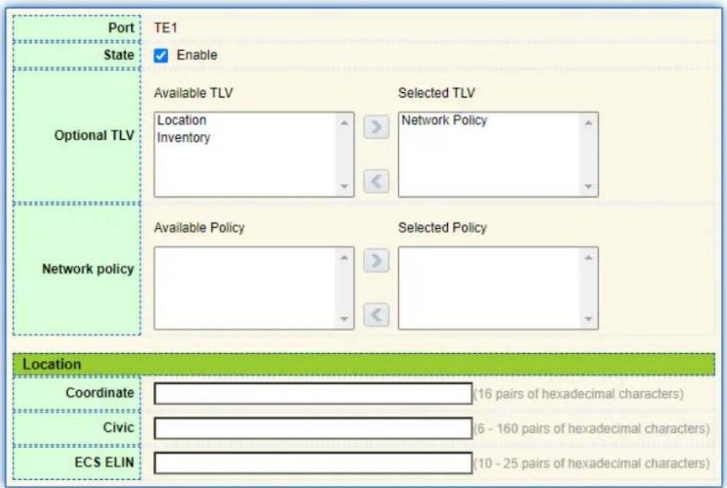
11.4 MED Port Setting
Instructions
- Click the "Discovery > LLDP > MED Port Setting" in the navigation bar as follows.
| Entry | Port | State | Network Policy | Location | Inventory | |||
| Active | Application | |||||||
| 1 | TE1 | Enabled | Yes | No | No | |||
| 2 | TE2 | Enabled | Yes | No | No | |||
| 3 | TE3 | Enabled | Yes | No | No | |||
| 4 | TE4 | Enabled | Yes | No | No | |||
| 5 | TE5 | Enabled | Yes | No | No | |||
| 6 | TE6 | Enabled | Yes | No | No | |||
| 7 | TE7 | Enabled | Yes | No | No | |||
| 8 | TE8 | Enabled | Yes | No | No | |||
Edit
Edit MED Port Setting
text_image
Port TE1 State Enable Optional TLV Available TLV Selected TLV Location Inventory Network Policy Network policy Available Policy Selected Policy Location Coordinate (16 pairs of hexadecimal characters) Civic (6 - 160 pairs of hexadecimal characters) ECS ELIN (10 - 25 pairs of hexadecimal characters)Apply
Close
Interface data are as follows.
| Configuration | Description |
| Items | |
| Entry | Serial No. of MED port setting |
| Port | Port list |
| State | Port enable status |
| Network Policy | Configure and publish network policy TLV |
| Location | Configure and publish location TLV |
| Inventory | Configure and publish inventory TLV |
11.5 Packet View
Instructions
- Click the "Discovery > LLDP > Packet View" in the navigation bar as follows.
Packet View Table
| Entry | Port | In-Use (Bytes) | Available (Bytes) | Operational Status | |
| ○ | 1 | TE1 | 38 | 1450 | Not Overloading |
| ○ | 2 | TE2 | 38 | 1450 | Not Overloading |
| ○ | 3 | TE3 | 38 | 1450 | Not Overloading |
| ○ | 4 | TE4 | 38 | 1450 | Not Overloading |
| ○ | 5 | TE5 | 38 | 1450 | Not Overloading |
| ○ | 6 | TE6 | 38 | 1450 | Not Overloading |
| ○ | 7 | TE7 | 38 | 1450 | Not Overloading |
| ○ | 8 | TE8 | 38 | 1450 | Not Overloading |
Detail
11.6 Local Information
Instructions for device summary:
- Click the "Discovery > LLDP > Local Information" in the navigation bar as follows.
Device Summary
| Chassis ID Subtype | MAC address |
| Chassis ID | 00:4F:4C:00:70:32 |
| System Name | WEB-2TX1602 |
| System Description | WEB-2TX1602 |
| Supported Capabilities | Bridge, Router |
| Enabled Capabilities | Bridge, Router |
| Port ID Subtype | Local |
Instructions for port status table:
- Click the "Discovery > LLDP > Local Information" in the navigation bar as follows.
Port Status Table
| Entry | Port | LLDP State | LLDP-MED State | ||
| ○ | 1 | TE1 | Normal | Enabled | |
| ○ | 2 | TE2 | Normal | Enabled | |
| ○ | 3 | TE3 | Normal | Enabled | |
| ○ | 4 | TE4 | Normal | Enabled | |
| ○ | 5 | TE5 | Normal | Enabled | |
| ○ | 6 | TE6 | Normal | Enabled | |
| ○ | 7 | TE7 | Normal | Enabled | |
| ○ | 8 | TE8 | Normal | Enabled |
Detail
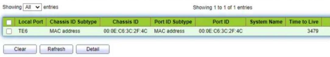
11.7 Neighbor
Instructions for LLDP neighbor displaying
- Click the "Discovery > LLDP > Neighbor" in the navigation bar as follows.
Neighbor Table
text_image
Showing All entries Showing 1 to 1 of 1 entries Local Port Chassis ID Subtype Chassis ID Port ID Subtype Port ID System Name Time to Live TE6 MAC address 00:0E:C6:3C:2F:4C MAC address 00:0E:C6:3C:2F:4C 3479 Clear Refresh Detail11.8 Statistics
Instructions:
- Click the "Discovery > LLDP > Statistics" in the navigation bar as follows.
Global Statistics
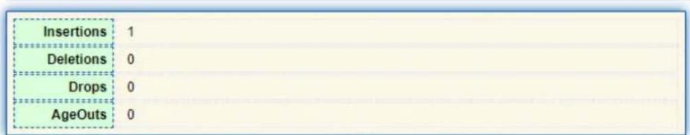
text_image
Insertions 1 Deletions 0 Drops 0 AgeOuts 0
Statistics Table
| Entry | Port | Transmit Frame | Receive Frame | Receive TLV | NeighborTimeout | |||||
| Total | Total | Discard | Error | Discard | Unrecognized | |||||
| 1 | TE1 | 0 | 0 | 0 | 0 | 0 | 0 | 0 | ||
| 2 | TE2 | 0 | 0 | 0 | 0 | 0 | 0 | 0 | ||
| 3 | TE3 | 0 | 0 | 0 | 0 | 0 | 0 | 0 | ||
| 4 | TE4 | 0 | 0 | 0 | 0 | 0 | 0 | 0 | ||
| 5 | TE5 | 0 | 0 | 0 | 0 | 0 | 0 | 0 | ||
| 6 | TE6 | 7 | 4 | 0 | 0 | 0 | 0 | 0 | ||
| 7 | TE7 | 0 | 0 | 0 | 0 | 0 | 0 | 0 | ||
| 8 | TE8 | 0 | 0 | 0 | 0 | 0 | 0 | 0 | ||

12 Multicast
12.1 General
12.1.1 Property
Instructions:
- Click the "Multicast > General > Property" in the navigation bar as follows.
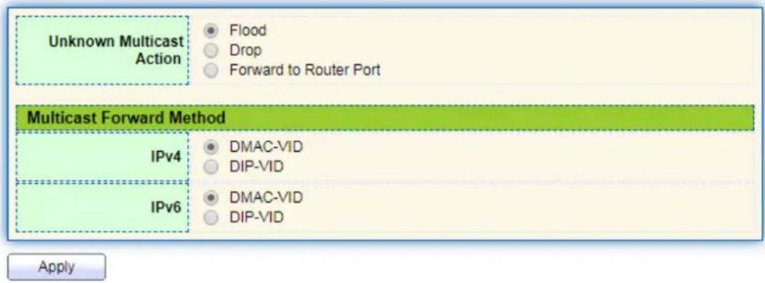
text_image
Unknown Multicast Action Flood Drop Forward to Router Port Multicast Forward Method IPv4 DMAC-VID DIP-VID IPv6 DMAC-VID DIP-VID Apply12.1.2 Group Address
According to the previous request mode of multicast, the multicast router will copy and forward data to each VLAN containing receivers when users in different VLANs request the same multicast group, which wastes a great deal of bandwidth. IGMP Snooping configures multicast VLAN by connecting the different users of switch ports to a same multicast VLAN to receive multicast data. In this way, multicast flow can only be transmitted within a multicast VLAN, thus saving bandwidth. In addition, security and bandwidth are guaranteed because multicast VLANs are completely isolated from user VLANs.
Instructions
- Click the "Multicast > Group Address", "Add" a new static multicast item, and "Edit" the existing ones as follows:
Group Address Table

text_image
Showing All entries Showing 0 to 0 of 0 entries VLAN Group Address Member Type Life (Sec) 0 results found. Add Edit Delete Refresh First Previous 1 Next LastInterface data are as follows.
| Configuration Items | Description |
| VLAN | VLAN ID to which the multicast group belongs. Drop down to select an existing VLAN. |
| Multicast Address | Enter the multicast address |
| Member | Add multicast member(s) |
- Fill in corresponding configuration items.
- "Apply" and finish as follows.
Group Address Table

text_image
Showing All entries Showing 1 to 1 of 1 entries VLAN Group Address Member Type Life (Sec) 1 224.1.1.111 TE1 Static Add Edit Delete Refresh First Previous 1 Next Last12.1.3 Router Port
Configure and view multicast router port Instructions:
- Click the "Multicast > General > Router Port" in the navigation bar as follows.
Router Port Table
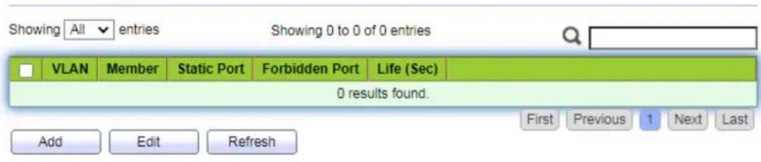
text_image
Showing All entries Showing 0 to 0 of 0 entries VLAN Member Static Port Forbidden Port Life (Sec) 0 results found. Add Edit Refresh First Previous 1 Next Last12.2 IGMP Snooping
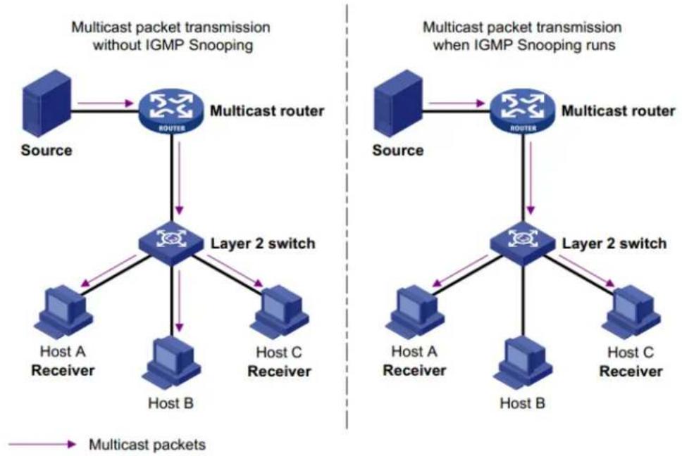
IGMP Snooping (Internet Group Management Protocol Snooping) is a constraint mechanism on L2 devices to manage and control multicast groups.
By analyzing the IGMP messages received, L2 devices establish a mapping between ports and MAC multicast addresses and forward the multicast data accordingly.
As shown below, multicast data are transmitted on L2 without IGMP snooping. When IGMP snooping runs, known multicast group data are transmitted to specified receivers while unknown multicast data are still on Layer 2.
flowchart
graph TD
    subgraph "Multicast packet transmission without IGMP Snooping"
        A["Source"] --> B["Multicast router"]
        B --> C["Layer 2 switch"]
        C --> D["Host A Receiver"]
        C --> E["Host B"]
        C --> F["Host C Receiver"]
    end
    subgraph "Multicast packet transmission when IGMP Snooping runs"
        G["Source"] --> H["Multicast router"]
        H --> I["Layer 2 switch"]
        I --> J["Host A Receiver"]
        I --> K["Host B"]
        I --> L["Host C Receiver"]
    end
    B <--> H
    style A fill:#4A90E2,stroke:#333
    style G fill:#4A90E2,stroke:#333
12.2.1 Property
IGMP Snooping is on the L2 switch between the multicast routers and the user hosts, applicable to deploy IPv4 networks. It is configured in a VLAN to snoop the IGMP/MLD messages transmitted between routers and hosts, and to establish a L2 forwarding table for multicast data, in order to manage and control the multicast data forwarding in L2 network.
Global IGMP Snooping function should be enabled since it is disabled by default. Instructions:
- Click the "Multicast > IGMP Snooping > Property", select the VLAN to be configured from the created VLAN info, and "Edit" the details as follows:

text_image
State Version Report Suppression Enable IGMPv2 IGMPv3 Enable ApplyVLAN Setting Table
| ☐ | VLAN | Operational Status | Router Port Auto Learn | Query Robustness | Query Interval | Query Max Response interval | Last Member Query Counter | Last Member Query Interval | Immediate Leave |
| ☐ | 1 | Disabled | Enabled | 2 | 125 | 10 | 2 | 1 | Disabled |
| Edit |
Interface data are as follows.
| Configuration Items | Description |
| VLAN | VLAN ID to be configured |
| State | Enable or disable the IGMP Snooping in this VLAN |
| Router Port Auto Learn | Enable or disable route port automatic learning |
| Immediate leave | Multicast members leave quickly |
| Query Robustness | The Robustness Variable allows tuning for the expected packet loss on a network |
| Query Interval | The interval between message queries |
| Query Max Response Interval | Timeout (over the max response time) of a query message |
| Last Member Query Counter | Max number of queries for a specified group |
| Last Member Query Interval | The interval between message queries for a specified group |
- Fill in corresponding configuration items.
- "Apply" and finish.
13 Security
13.1 Management Access
13.1.1 Management Service
Instructions for Telnet:
- Click the "Security > Management Access > Management Service", enter management service interface as follows:
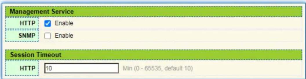
text_image
Management Service HTTP ✓ Enable SNMP □ Enable Session Timeout HTTP 10 Min (0 - 65535, default 10)
Instructions for SNMP:
- Click the "Security > Management Access > Management Service", enter management service interface as follows:

text_image
Management Service HTTP ✓ Enable SNMP ✓ Enable Session Timeout HTTP 10 Min (0 - 65535, default 10)
13.2 DHCP Snooping
For sake of security, the network administrator may need to record the IP address of a user surfing the Internet and to confirm the correspondence between the IP address obtained from DHCP Server and the host's MAC address.
Switch can record the user's IP address through the secure DHCP relay at the network layer.
Switch can monitor DHCP messages and record the user's IP address through DHCP Snooping at the data link layer. In addition, private DHCP Server in the network may lead to wrong IP address for the user. To ensure that users obtain IP addresses through legal DHCP Server, the DHCP Snooping security mechanism divides the ports into Trust Port and Untrust Port.
Trust Port directly or indirectly connects legal DHCP Server. It forwards the DHCP messages received to ensure the correct IP address for DHCP Client. Untrust Port connects illegal DHCP Server. DHCPACK and DHCPOFFER messages received from the DHCP Server on the Untrust Port will be discarded to prevent incorrect IP addresses.

flowchart
graph LR
    subgraph DHCP Client
        A1["DHCP Client"] -->|Eth1/0/1| SwitchA["Switch A (DHCP Snooping)"]
        A2["DHCP Client"] -->|Eth1/0/1| SwitchA
        A3["DHCP Client"] -->|Eth1/0/1| SwitchA
    end
    subgraph DHCP Server
        B1["DHCP Server"] --> C["Internet"]
        B2["Switch B (DHCP Relay)"] --> C
    end
    SwitchA -->|Eth1/0/2| SwitchB["Switch B (DHCP Relay)"]
Typical Networking of DHCP Snooping
The following methods are used to obtain the IP address and user MAC address from DHCP Server:
- Snooping the DHCPREQUEST message
- Snooping the DHCPACK message
13.2.1 Property
Enable DHCP Snooping
Instructions:
- Click the "Security > DHCP Snooping > Property". DHCP Snooping interface is divided into global configuration and port configuration. Select the port to be modified in the port configuration and "Edit" the details as follows:
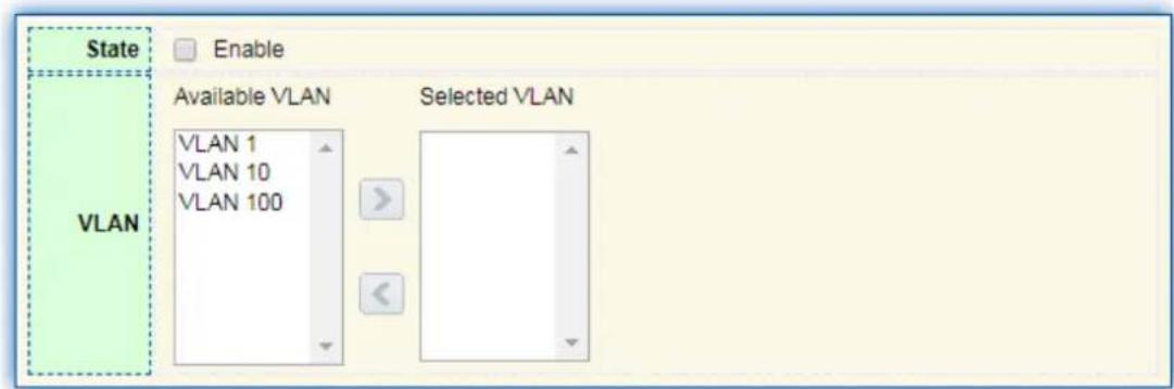
text_image
State Enable VLAN Available VLAN Selected VLAN VLAN 1 VLAN 10 VLAN 100
| □ | Entry | Port | Trust | Verify Chaddr | Rate Limit | |
| □ | 1 | TE1 | Disabled | Disabled | Unlimited | |
| □ | 2 | TE2 | Disabled | Disabled | Unlimited | |
| □ | 3 | TE3 | Disabled | Disabled | Unlimited | |
| □ | 4 | TE4 | Disabled | Disabled | Unlimited |
Interface data are as follows.
| Configuration Items | Description |
| State | Enable and disable the DHCP Snooping |
| VLAN | Valid VLAN No. of DHCP Snooping |
| Port | Configure the port No. of DHCP Snooping |
| Trust | Whether the port is a Trust Port |
| Client Address Inspection | Whether the consistency inspection for Client addresses is enabled |
| Rate Limit | Whether the port enables rate limit and configures the value |
- Fill in corresponding configuration items.
- "Apply" and finish as follows.
13.2.2 IMPV Binding
In DHCP network, users (non-DHCP users) obtaining IP addresses statically may attack the network by imitating DHCP Server, constructing DHCP Request message, etc. Legal DHCP users may suffer from security risks when using the network normally.
Enabling the static MAC entries based on the interface generated by DHCP Snooping binding table can prevent such attacks. The device then, based on the DHCP Snooping binding table corresponding to all DHCP users, automatically executes the command to generate static MAC entries and disable the interface's learning ability of dynamic entries. Only messages that match the source MAC and static MAC entries can flow through the interface. Therefore, for non-DHCP users, only the messages of static MAC entries that are manually configured by the administrators can flow through, while others will be discarded.
Instructions:
- Click the "Security > IP Source Guard > IMPV Binding", "Add" a new binding group of IP-MAC-Port-VLAN as follows:
IP-MAC-Port-VLAN Binding Table
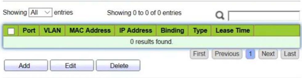
text_image
Showing All entries Showing 0 to 0 of 0 entries Port VLAN MAC Address IP Address Binding Type Lease Time 0 results found. Add Edit Delete First Previous 1 Next LastInterface data are as follows.
| Configuration Items | Description |
| Port | The port No. of binding group |
| VLAN | VLAN ID bound |
| Binding | Select the binding relation from IPMV and IPV |
| MAC Address | MAC address bound |
| IP Address | IP address bound |
-
Fill in corresponding configuration items.
-
"Apply" and finish as follows.
14 QoS
QoS (Quality of Service) assesses the ability of service providers to meet customer needs and the ability of transmitting packets over the Internet. Diversified services can be assessed based on different aspects. QoS usually refers to the evaluation of service capabilities that support core requirements such as bandwidth, delay, delay variation, and packet loss rate during delivery. Bandwidth, also known as throughput, refers to the average business flow within a certain period of time, with the unit of Kbit/s. Delay refers to the average time required for business flowing through the network. For a network device, the followings are general levels of delay requirements. There are two delay levels, that is, the high-priority business can be served as soon as possible by scheduling method of priority queue, while the low-priority business gets services after that. Delay variation refers to the time change of business flowing through the network. Packet loss rate refers to the percentage of lost business flow during transmission. As modern transmission systems are very reliable, information is often lost in network congestion. Packet loss due to queue overflow is the most common situation.
All messages in a traditional IP network are treated equally. Every network device processes the messages on a FIFO basis, and makes every effort to transmit them to
destinations without guaranteeing reliability, transfer delay, or other performance.
Network service quality is constantly improved as new applications keep springing up in the rapidly changing IP network. For example, VoIP, video and other delay-sensitive services have set higher standards on message transmission delay. Message transmission in a short period has been the common trend. In order to support voice, video and data services with different requirements, the network needs to identify business types and provide corresponding services.
The ability to distinguish business types is the prerequisite to provide corresponding services, so the traditional best-effort service no longer meets the application needs. Therefore, QoS comes into being. It regulates the network flow to avoid and handle network congestion and reduce packet loss rate. Meanwhile, users can enjoy dedicated bandwidths while business can improve service quality, thus perfecting the network service capacity.
QoS priorities vary with message types. For instance, the VLAN message uses 802.1p, also known as the CoS (Class of Service) field, while the IP message uses DSCP. To maintain the priority, these fields need to be mapped at the gateway connected with various networks when messages flow through the network.
802.1p priority in the VLAN frame header
Typically, VLAN frames are interacted between Layer 2 devices. The PRI field (i.e. 802.1p priority), or CoS field, in the VLAN frame header identifies the quality of service requirements according to the definitions in IEEE 802.1Q.
802.1p priority in the VLAN frame
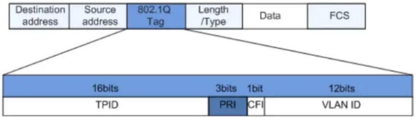
flowchart
graph TD
    A["Destination address"] --> B["Source address"]
    B --> C["802.1Q Tag"]
    C --> D["Length /Type"]
    D --> E["Data"]
    E --> F["FCS"]
    G["16bits"] --> H["TPID"]
    I["3bits"] --> J["PRI"]
    K["1bit"] --> L["CFI"]
    M["12bits"] --> N["VLAN ID"]
The 802.1Q header contains 3-bit PRI fields. PRI field defines 8 CoS of business priority ranging from 7 to 0 from high to low.
IP Precedence/DSCP Field
According to RFC791 definition, ToS (Type of Service) domain in the IP message header is composed of 8 bits. Among them, the 3-bit long Precedence field, as located in the following, identifies the IP message priority.
IP Precedence/DSCP Field
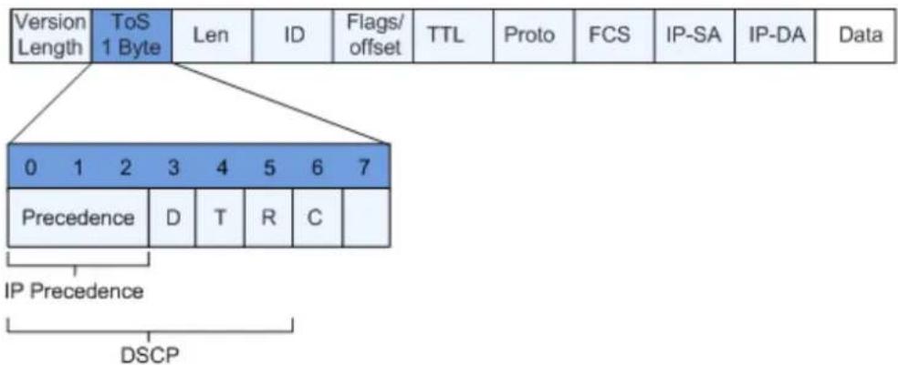
text_image
Version Length ToS 1 Byte Len ID Flags/ offset TTL Proto FCS IP-SA IP-DA Data 0 1 2 3 4 5 6 7 Precedence D T R C IP Precedence DSCP0 to 2 bits are Precedence fields representing the 8 priorities of message transmission ranging from 7 to 0 from high to low, with either Level 7 or 6 as the highest priority that is generally reserved for routing or updating network control communication. User-level applications only have access to Level 0 to 5.
ToS domain, in addition to Precedence fields, also includes D, T and R bits: D-bit represents the Delay requirement (0 for normal delay and 1 for low delay). T-bit represents the throughput (0 for normal throughput and 1 for high throughput). R-bit represents the reliability (0 for normal reliability and 1 for high reliability). ToS domain reserves the 6 and 7 bits.
RFC1449 redefines the ToS domain by adding a C-bit to represent the Monetary Cost. The IETF DiffServ group then redefines the 0 to 5 bits of ToS domain in the IPv4 message header of RFC2474 as DSCP and renames it as DS (Differentiated Service) byte as shown in the figure above.
The first 6 bits (0-5 bits) of DS field distinguish the DSCP (DS Code Point), and the higher 2 bits (6-7 bits) are reserved. The lower 3 bits (0-2 bits) are CSCP (Class Selector Code Point), with the same CSCP value representing the DSCP of the same class. DS nodes select corresponding PHB (Per-Hop Behavior) according to DSCP values.
14.1 General
14.1.1 Property
Network congestion resulting from the competition for resource use rights among messages at the same time is usually solved by queue scheduling, thus avoiding intermittent congestions. Queue scheduling technologies include SP (Strict-Priority), WRR (Weighted Round Robin).
Instructions for global and port scheduling configuration
- Click the "QoS > General > Property" in the navigation bar as follows.
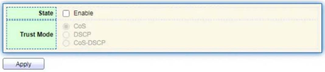
text_image
State Enable Trust Mode CoS DSCP CoS-DSCP ApplyPort Setting Table
| ☐ | Entry | Port | CoS | Trust | Remarking | ||
| CoS | DSCP | ||||||
| ☐ | 1 | TE1 | 0 | Enabled | Disabled | Disabled | |
| ☐ | 2 | TE2 | 0 | Enabled | Disabled | Disabled | |
| ☐ | 3 | TE3 | 0 | Enabled | Disabled | Disabled | |
| ☐ | 4 | TE4 | 0 | Enabled | Disabled | Disabled | |
Interface data of global configuration are as follows.
| ConfigurationItems | Description |
| State | Switch of global QoS function |
| Trust Mode | It can be divided into CoS, DSCP, CoS-DSCP |
Interface data of port configuration are as follows.
| Configuration Items | Description |
| CoS | Ranging from 0 to 7 |
| Port Trust Mode | Switch of port QoS function |
| CoS | Mark the CoS field |
| DSCP | Mark the DSCP field |
14.1.2 Queue Scheduling
- Click the "QoS > General > Queue Scheduling". "Apply" and finish as follows.
Queue Scheduling Table
| Queue | Method | ||||
| Strict Priority | WRR | Weight | WRR Bandwidth (%) | ||
| 1 |  | Og | 1 | ||
| 2 |  | Og | 2 | ||
| 3 |  | Og | 3 | ||
| 4 |  | Og | 4 | ||
| 5 |  | Og | 5 | ||
| 6 |  | Og | 9 | ||
| 7 |  | Og | 13 | ||
| 8 |  | Og | 15 | ||

Interface data are as follows.
| Configuration Items | Description |
| Strict Priority | SP mode |
| WRR | WRR mode |
| Weight | Bandwidth percentage of WRR accounted for by Queue |
14.1.3 CoS Mapping
- Click the "QoS > General > CoS Mapping" in the navigation bar. "Apply" and finish as follows.
CoS to Queue Mapping
| CoS | Queue | |
| 0 | 1▼ | |
| 1 | 2▼ | |
| 2 | 3▼ | |
| 3 | 4▼ | |
| 4 | 5▼ | |
| 5 | 6▼ | |
| 6 | 7▼ | |
| 7 | 8▼ |

Queue to CoS Mapping
| Queue | CoS | |
| 1 | 0▼ | |
| 2 | 1▼ | |
| 3 | 2▼ | |
| 4 | 3▼ | |
| 5 | 4▼ | |
| 6 | 5▼ | |
| 7 | 6▼ | |
| 8 | 7▼ |

Interface data are as follows.
| Configuration Items | Description |
| CoS | 802.1p priority |
| Queue | Port queue |
14.1.4 DSCP Mapping
- Click the "QoS > General > DSCP Mapping". "Apply" and finish as follows.
DSCP to Queue Mapping
| DSCP | Queue | DSCP | Queue | DSCP | Queue | DSCP | Queue | |
| 0 [CS0] | 1 ▼ | 16 [CS2] | 3 ▼ | 32 [CS4] | 5 ▼ | 48 [CS6] | 7 ▼ | |
| 1 | 1 ▼ | 17 | 3 ▼ | 33 | 5 ▼ | 49 | 7 ▼ | |
| 2 | 1 ▼ | 18 [AF21] | 3 ▼ | 34 [AF41] | 5 ▼ | 50 | 7 ▼ | |
| 3 | 1 ▼ | 19 | 3 ▼ | 35 | 5 ▼ | 51 | 7 ▼ | |
| 4 | 1 ▼ | 20 [AF22] | 3 ▼ | 36 [AF42] | 5 ▼ | 52 | 7 ▼ | |
| 5 | 1 ▼ | 21 | 3 ▼ | 37 | 5 ▼ | 53 | 7 ▼ | |
| 6 | 1 ▼ | 22 [AF23] | 3 ▼ | 38 [AF43] | 5 ▼ | 54 | 7 ▼ | |
| 7 | 1 ▼ | 23 | 3 ▼ | 39 | 5 ▼ | 55 | 7 ▼ | |
| 8 [CS1] | 2 ▼ | 24 [CS3] | 4 ▼ | 40 [CS5] | 6 ▼ | 56 [CS7] | 8 ▼ | |
| 9 | 2 ▼ | 25 | 4 ▼ | 41 | 6 ▼ | 57 | 8 ▼ | |
| 10 [AF11] | 2 ▼ | 26 [AF31] | 4 ▼ | 42 | 6 ▼ | 58 | 8 ▼ | |
| 11 | 2 ▼ | 27 | 4 ▼ | 43 | 6 ▼ | 59 | 8 ▼ | |
| 12 [AF12] | 2 ▼ | 28 [AF32] | 4 ▼ | 44 | 6 ▼ | 60 | 8 ▼ | |
| 13 | 2 ▼ | 29 | 4 ▼ | 45 | 6 ▼ | 61 | 8 ▼ | |
| 14 [AF13] | 2 ▼ | 30 [AF33] | 4 ▼ | 46 [EF] | 6 ▼ | 62 | 8 ▼ | |
| 15 | 2 ▼ | 31 | 4 ▼ | 47 | 6 ▼ | 63 | 8 ▼ |
Apply
Queue to DSCP Mapping
| Queue | DSCP | |
| 1 | 0 [CS0] ▼ | |
| 2 | 8 [CS1] ▼ | |
| 3 | 16 [CS2] ▼ | |
| 4 | 24 [CS3] ▼ | |
| 5 | 32 [CS4] ▼ | |
| 6 | 40 [CS5] ▼ | |
| 7 | 48 [CS6] ▼ | |
| 8 | 56 [CS7] ▼ |
Apply
Interface data are as follows.
| ConfigurationItems | Description |
| DSCP | Value of IP DHCP domain priority |
| Queue | Port queue |
14.2 Rate limit
14.2.1 Ingress / Egress Port
It refers to the rate restriction on transmitting and receiving data at physical interfaces.
Restrict the rate limiting at the egress before transmitting flow, thus controlling all outgoing message flow;
Restrict the rate limiting at the ingress before receiving flow, thus controlling all incoming message flow;
Instructions:
- Click the "QoS > Rate Limit > Ingress / Egress Port" in the navigation bar to choose a rate-limiting port and check the current configuration as follows:
Ingress / Egress Port Table
| Entry | Port | Ingress | Egress | |||
| State | Rate (Kbps) | State | Rate (Kbps) | |||
| 1 | TE1 | Disabled | Disabled | |||
| 2 | TE2 | Disabled | Disabled | |||
| 3 | TE3 | Disabled | Disabled | |||
| 4 | TE4 | Disabled | Disabled | |||
| 5 | TE5 | Disabled | Disabled | |||
| 6 | TE6 | Disabled | Disabled | |||
| 7 | TE7 | Disabled | Disabled | |||
| 8 | TE8 | Disabled | Disabled | |||
- Select the port (s) for rate limiting, "Edit" it at the bottom to switch the function and specify the rate. "Apply" and finish as follows:
Edit Ingress / Egress Port

text_image
Port TE1-TE2 Ingress Enable 10000000 Kbps (16 - 10000000) Egress Enable 10000000 Kbps (16 - 10000000) Apply CloseInterface data are as follows.
| Configuration Items | Description | |
| Ingress | Enabled | Rate limiting switch |
| Rate | Rate ranges from 16 to 10,000,000 Kbps | |
| Egress | Enabled | Rate limiting switch |
| Rate | Rate ranges from 16 to 10,000,000 Kbps | |
15 Diagnostics
15.1 Ping
Ping command checks the availability of specified IP addresses and host names and transmits statistics accordingly.
Instructions:
- Click the "Diagnostics > Ping" in the navigation bar to enter a host name or an IP address, as well as the number of tests as follows:
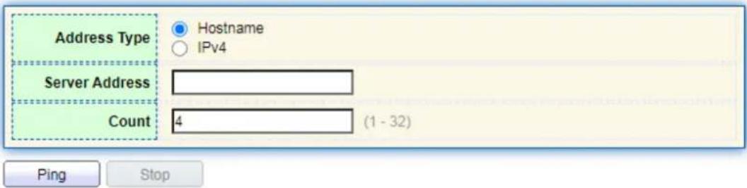
text_image
Address Type Hostname IPv4 Server Address Count 4 (1 - 32) Ping Stop- Click the "Ping" to accept the packet-transmitting test from system to verify address validity, and output the result as follows:
Ping Result
| Packet Status | |
| Status | Success. |
| Transmit Packet | 4 |
| Receive Packet | 4 |
| Packet Lost | 0 % |
| Round Trip Time | |
| Min | 0 ms |
| Max | 0 ms |
| Average | 0 ms |
15.2 Copper Test
Copper test evaluates the ingress cable state and locates the faults (about 5 m by error) according to the reflected voltage strength
Instructions:
- Click the "Diagnostics > Copper Test" in the navigation bar to select a port for test as follows:
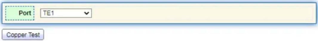
text_image
Port TE1 Copper Test- Click the "Copper Test" and output the result as follows:
Copper Test Result
| Cable Status | |
| Port | TE2 |
| Result | OK |
| Length | N/A |
15.3 Fiber Module
Can be used to view optical module DDM information Instructions:
- Click the "Diagnostics > Fiber Module" in the navigation bar to select a port for test as follows:
Fiber Module Table
| Port | Temperature (C) | Voltage (V) | Current (mA) | Output Power (mW) | Input Power (mW) | OE Present | Loss of Signal |
| TE1 | N/A | N/A | N/A | N/A | N/A | Remove | Loss |
| TE2 | N/S | N/S | N/S | N/S | N/S | Insert | Loss |
| TE3 | 67.03 | 3.33 | 32.33 | 0.25 | 0.00 | Insert | Loss |
| TE4 | N/S | N/S | N/S | N/S | N/S | Insert | Normal |
| TE5 | N/A | N/A | N/A | N/A | N/A | Remove | Loss |
| TE6 | N/A | N/A | N/A | N/A | N/A | Remove | Loss |
| TE7 | N/A | N/A | N/A | N/A | N/A | Remove | Loss |
| TE8 | N/A | N/A | N/A | N/A | N/A | Remove | Loss |
16 Management
16.1 User Account
Users can check and modify the current username, password and authority of the switch.
Instructions:
- Click the "Management > User Account" in the navigation bar to discover the username of "admin" and the privilege of "Admin" by default as follows:
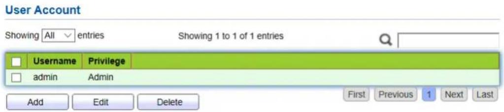
text_image
User Account Showing All entries Showing 1 to 1 of 1 entries Username Privilege admin Admin Add Edit Delete First Previous 1 Next Last- "Add" a new user account and "Edit" the selected user attribute as follows:
Add User Account
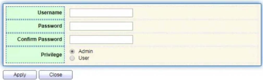
text_image
Username Password Confirm Password Privilege • Admin • User Apply Close16.2 Firmware
System version firmware upgrade
Instructions:
- Click the "Management > Firmware > Manual Upgrade" in the navigation bar as follows:

text_image
File Type Action Method Filename Choose File No file chosen Image Upgrade TFTP HTTP Apply16.3 Configuration
16.3.1 Manual Upgrade
System configuration upgrade or backup
Instructions for configuration file upgrade:
- Click the "Management > Configuration > Manual Upgrade" click the "Upgrade" in mode of "TFTP" or "HTTP", select the corresponding files to be upgraded (servers should be illustrated in TFTP mode). "Apply" and finish as follows:
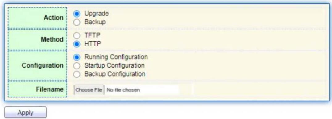
text_image
Action Upgrade Backup Method TFTP HTTP Configuration Running Configuration Startup Configuration Backup Configuration Filename Choose File No file chosen ApplyInstructions for file backup configuration:
- click the "Backup" in mode of "TFTP" or "HTTP", select the files or logs to be upgraded (servers should be illustrated in TFTP mode). "Apply" and finish as follows.
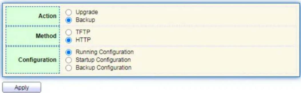
text_image
Action ○ Upgrade ● Backup Method ○ TFTP ● HTTP Configuration ● Running Configuration ○ Startup Configuration ○ Backup Configuration Apply16.3.2 Save Configuration
Save system configuration or restore configuration to factory default Instructions:
- Click the "Management > Configuration > Save Configuration" in the navigation bar as follows:

text_image
Source File Running Configuration Startup Configuration Backup Configuration Destination File Startup Configuration Backup Configuration Apply Restore Factory DefaultNote:
- Click the "Factory Reset" and "Device Restart" to restore factory settings. Save the "Running Configuration" as the "Start Configuration" (which can be saved as "Backup Configuration" or "Running Configuration") and the "Backup Configuration" (which can be saved as the "Start Configuration" or "Running Configuration").
Instructions for the second method of system preservation:
- Click the "Save" on the upper right to save the running configuration as the start configuration as follows.
Save | Logout | Reboot
Save running configuration to startup configuration. Do you want to continue?
OK
Cancel
16.4 SNMP
SNMP (Simple Network Management Protocol) is widely used in TCP/IP network. It manages devices by the central computer which operates network management software (i.e. network management workstation). SNMP is:
- Simple: The polling-driving SNMP has the fundamental functionality set that is applicable to small-scale environment with fast speed and low cost. Besides, UDP-driven SNMP is compatible with most devices. Powerful: SNMP aims to ensure the management info transmission between two nodes so that administrators can retrieve, modify and troubleshoot the info easily. There are 3 common versions namely SNMPv1, v2c and v3. Its system contains NMS (Network Management System), Agent, Management object and MIB (Management Information Base).
- NMS, as the management center, will manage all devices. Each device under management includes the resident Agent, MIB and management objects. NMS interacts with the Agent running on the management object which will operate the MIB to execute NMS orders.
SNMP management model
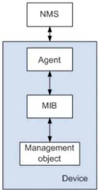
flowchart
graph TD
    A["NMS"] <--> B["Agent"]
    B <--> C["MIB"]
    C <--> D["Management object"]
    style A fill:#f9f,stroke:#333
    style B fill:#ccf,stroke:#333
    style C fill:#cfc,stroke:#333
    style D fill:#fcc,stroke:#333
NMS
- As the network administrator, NMS manages/monitors network devices by SNMP on its server. It can request the Agent to inquire or modify specified parameter(s). NMS can receive the Trap actively sent by the Agent to be updated with the states of the managed devices.
Agent
- As an agent process of the managed devices, it maintains device data and responds to the NMS requests by reporting management data. Agent will fulfill relevant orders through MIB Table and transmit the results back to NMS after receiving its request. Devices will take the initiative to transmit info related to the current statues of devices to NMS through Agent once a fault or another event occurs.
Management object
- It refers to the object under management. Each device may have more than one objects, including a piece of hardware (e.g. an interface board), partial hardware and
software (e.g. routing protocol), as well as other configuration item sets MIB
- MIB is a database specifying the variables maintained by the management object (i.e. the info that can be inquired and set by the Agent). MIB defines the attributes of the management object, including the name, state, access right and data type. The following functions can be realized through MIB: Agent will master the instant device info by inquiring MIB and set the state configuration items by changing MIB.
Note:
- Please enable the SNMP global switch before connecting to SNMP
- Please enter the path below to configure the global switch for SNMP, or refer to section 11.1.1
Menu Path: "Security > Management Access > Management Service"
16.4.1 Community
- Click the "Management > SNMP > Community" in the navigation bar as follows.
Community Table
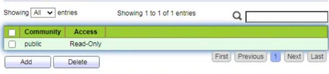
text_image
Showing All entries Showing 1 to 1 of 1 entries Community Access public Read-Only Add Delete First Previous 1 Next LastInterface data are as follows.
| Configuration Items | Description |
| Community | Community configuration |
| Access: | Authority: read only or read-write |
- "Add" the corresponding configuration. "Apply" and finish.
Add Community

text_image
Community Access Read-Only Read-Write Apply Close16.4.2 Trap Event
- Click the "Management > SNMP > Trap Event" in the navigation bar as follows.
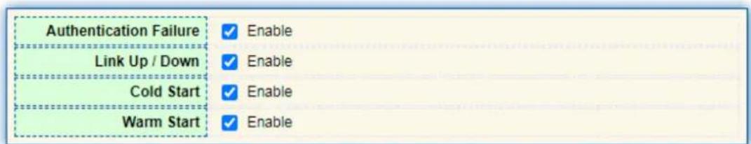
text_image
Authentication Failure Link Up / Down Cold Start Warm Start ✓ Enable ✓ Enable ✓ Enable ✓ Enable
Interface data are as follows.
| Configuration Items | Description |
| Authentication Failure | Authentication error |
| Link Up / Down | Port link up/down |
| Cold start | Cold start |
| Warm start | Warm start |
- "Apply" and finish.
16.4.3 Notification
- Click the "Management > SNMP > Notification" in the navigation bar as follows.
Notification Table
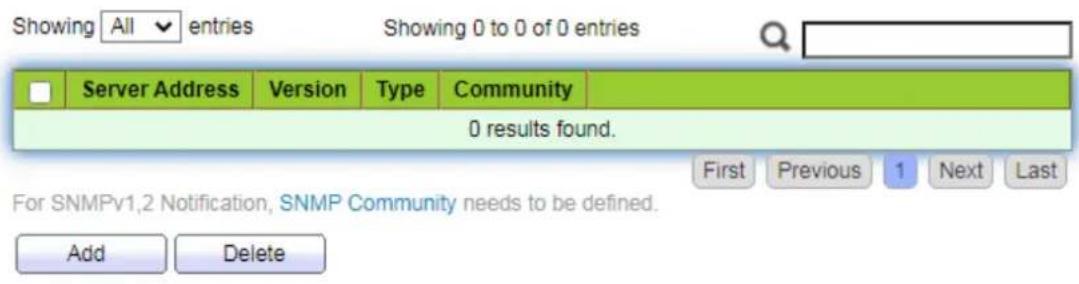
text_image
Showing All entries Showing 0 to 0 of 0 entries Server Address Version Type Community 0 results found. First Previous 1 Next Last For SNMPv1.2 Notification, SNMP Community needs to be defined. Add DeleteInterface data are as follows.
| Configuration Items | Description |
| Address Type | Address type: “Host Name”, “IPv4” or “IPv6” |
| Server Address | Server address info |
| Version | SNMP versions: v1, v2 and v3 |
| Type | Notification type: “Trap” or “Inform” |
| Community / User | Community or username |
- "Add" the corresponding configuration. "Apply" and finish.
Add Notification
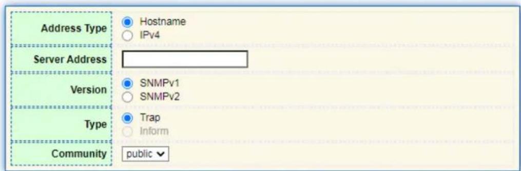
text_image
Address Type Hostname IPv4 Server Address SNMPv1 SNMPv2 Version Type Trap Inform Community public