DECS9252K - Range hood AEG - Free user manual and instructions
Find the device manual for free DECS9252K AEG in PDF.

User questions about DECS9252K AEG
0 question about this device. Answer the ones you know or ask your own.
Ask a new question about this device
Download the instructions for your Range hood in PDF format for free! Find your manual DECS9252K - AEG and take your electronic device back in hand. On this page are published all the documents necessary for the use of your device. DECS9252K by AEG.
USER MANUAL DECS9252K AEG
EN User manual Cooker Hood
USER MANUAL
natural_image
Simple line drawing of a kitchen chimney with three dots on the base (no text or symbols)CONTENTS
- SAFETY INFORMATION .... 3
- USE 7
- CARE AND CLEANING ....7
- CONTROLS 8
- LIGHTING 8
FOR PERFECT RESULTS
Thank you for choosing this AEG product. We have created it to give you impeccable performance for many years, with innovative technologies that help make life simpler – features you might not find on ordinary appliances. Please spend a few minutes reading to get the very best from it.
Visit our website for:

Get usage advice, brochures, trouble shooter, service information: www.aeg.com

Register your product for better service: www.registeraeg.com

Buy Accessories, Consumables and Original spare parts for your appliance: www.aeg.com/shop
CUSTOMER CARE AND SERVICE
Always use original spare parts.
When contacting our Authorised Service Centre, ensure that you have the following data available: Model, PNC, Serial Number.
The information can be found on the rating plate.

Warning / Caution-Safety information

General information and tips

Environmental information
Subject to change without notice.
1. SAFETY INFORMATION
For your safety and correct operation of the appliance, read this manual carefully before installation and use. Always keep these instructions with the appliance even if you move or sell it. Users must fully know the operation and safety features of the appliance.
The wire connection has to be done by specialized technician.
- The manufacturer will not be held liable for any damages resulting from incorrect or improper installation.
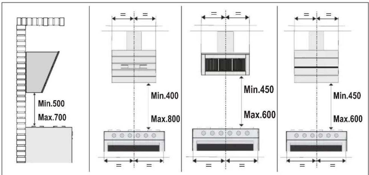
- The minimum safety distance between the cooker top and the extractor hood is 650 mm (some models can be installed at a lower height, please refer to the paragraphs on working dimensions and installation).
- If the instructions for installation for the gas hob specify a greater distance, this must be respected.
- Check that the mains voltage corresponds to that indicated on the rating plate fixed to the inside of the hood.
- Means for disconnection must be incorporated in the fixed wiring in accordance with the wiring rules.
- For Class I appliances, check that the domestic power supply guarantees adequate earthing.
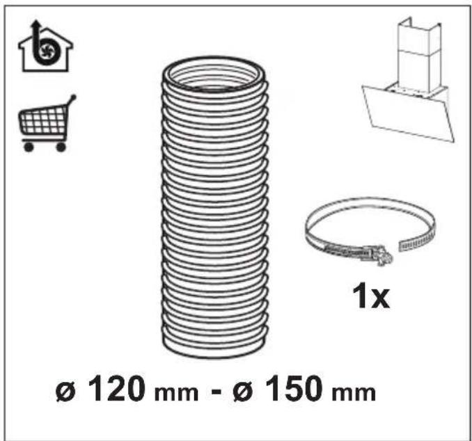
- Connect the extractor to the exhaust flue through a pipe of minimum diameter 120 mm. The route of the flue must be as short as possible.
- Regulations concerning the discharge of air have to be fulfilled.
- Do not connect the extractor hood to exhaust ducts carrying combustion fumes (boilers, fireplaces, etc.).
- If the extractor is used in conjunction with non-electrical appliances (e.g. gas burning appliances), a sufficient degree of aeration must be guaranteed in the room in order to prevent the backflow of exhaust gas. When the cooker hood is used in conjunction with appliances supplied with energy other than electric, the negative pressure in the room must not exceed 0,04 mbar to prevent fumes being drawn back into the room by the cooker hood.
- The air must not be discharged into a flue that is used for
exhausting fumes from appliances burning gas or other fuels.
- If the supply cord is damaged, it must be replaced from the manufacturer or its service agent.
- Connect the plug to a socket complying with current regulations, located in an accessible place.
- With regards to the technical and safety measures to be adopted for fume discharging it is important to closely follow the regulations provided by the local authorities.
WARNING: Before installing the Hood, remove the protective films.
- Use only screws and small parts in support of the hood.
WARNING: Failure to install the screws or fixing device in accordance with these instructions may result in electrical hazards.
- Do not look directly at the light through optical devices (binoculars, magnifying glasses...).
- Do not flambè under the range hood; risk of fire.
- This appliance can be used by children aged from 8 years and above and persons with reduced physical, sensory or mental capabilities or lack of experience and knowledge if they have been given supervision or instruction concerning use of the appliance in a safe way and understand the hazards involved. Children shall not play with the appliance. Cleaning and user maintenance shall not be made by children without supervision.
- Children should be supervised to ensure that they do not play with the appliance. - The appliance is not to be used by persons (including children) with reduced physical, sensory or mental capabilities, or lack of experience and knowledge, unless they have been given supervision or instruction.
⚠️ Accessible parts may become hot when used with cooking appliances.
- Clean and/or replace the Filters after the specified time period (Fire hazard). See paragraph Care and Cleaning.
- There shall be adequate ventilation of the room when the range hood is used at the same time as appliances burning gas or other fuels (not applicable to appliances that only
discharge the air back into the room).
- The symbol ☒ on the product or on its packaging indicates that this product may not be treated as household waste. Instead it shall be handed over to the applicable collection point for the recycling of electrical and electronic equipment. By ensuring this product is disposed of correctly, you will help prevent potential negative consequences for the environment and human health, which could otherwise be caused by inappropriate waste handling of this product. For more detailed information about recycling of this product, please contact your local city office, your household waste disposal service or the shop where you purchased the product.
2. USE
- The extractor hood has been designed exclusively for domestic use to eliminate kitchen smells.
- Never use the hood for purposes other than for which it has been designed.
- Never leave high naked flames under the hood when it is in operation.
- Adjust the flame intensity to direct it onto the bottom of the pan only, making sure that it does not engulf the sides.
- Deep fat fryers must be continuously monitored during use: overheated oil can burst into flames.
3. CARE AND CLEANING
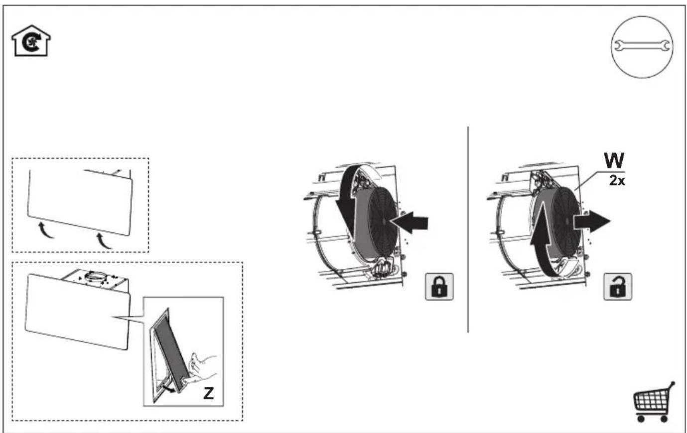
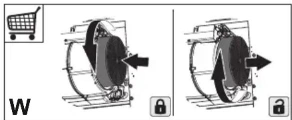
- The Activated charcoal filter is not washable and cannot be regenerated, and must be replaced approximately every 4 months of operation, or more frequently for particularly heavy usage (W).
text_image
W- The Grease filters must be cleaned every 2 months of operation, or more frequently for particularly heavy usage, and can be washed in a dishwasher (Z).

natural_image
Illustration of a hand interacting with a device on a screen, labeled 'Z' (no text or symbols on the diagram itself)- Clean the hood using a damp cloth and a neutral liquid detergent.
4. CONTROLS
 | (040) | (030) | (020) | (010) | (007) |  | (070) |
| I | I | I | I | I | I | I | I |
| I | I | I | I | I | I | I | I |
| I | I | I | I | I | I | I | I |
| A | B | C | D | E | F | G | H |
| Button | Function Led | |
| A | Changes the intensity of the Lighting each time the Button is pressed, in cycle, passing via Off. | - |
| B | Motor off. The Leds indicating the Speed of the motor | turn off. |
| Enables / Disables Keyboard Lock mode if pres-sed and held for 5 seconds. | All the Leds light up in cycle and run a start-up sequence. | |
| C | Activates speed one. The Leds indicating Speed one and MotorOff turn on. | |
| D | Activates speed two. The Leds indicating Speed two and MotorOff turn on. | |
| E | Activates the speed Intensive 1. This speed is ti-med to run for 10 minutes. At the end of this time the system will return to the speed set previously. It is disabled by pressing the Button or turning the Motor off. | The LED flashes. |
| F | Activates the speed Intensive 2. This speed is timed to run for 6 minutes. At the end of this time the system will return to the speed set previously. It is disabled by pressing the Button or turning the Motor off. | The LED flashes. |
| G | Activates / Deactivates Delay mode, with automa-tic shutdown of the Motor and the Lighting after 15 minutes. It is disabled by pressing the button or turning the motor off. | The Led lights up. |
| Pressing and holding the button for 5 seconds enables the remote control and the H2H function. Pressing and holding the button for 5 seconds disables the remote control and the H2H function. | 2 flashes from Leds on Buttons B+C.1 flash from Leds on Buttons B+C. | |
| H | With the filter alarm triggered, press the button to Reset the alarm. These indications are only visible when the motor is turned off. | When the procedure terminates, the indication shown previously turns off:Led H on = Indicates the need to wash the metal grease filters. The alarm is triggered after the Hood has been in operation for 100 working hours.Led H flashing = Indicates the need to change the activated charcoal filters, and also to wash the metal grease filters. The alarm is triggered after the Hood has been in operation for 200 working hours. |
| Press and hold the button for approximately 5 seconds, with all the loads turned off (Motor and Lights), to turn the Activated Charcoal Filter alarm on/off. | 2 flashes from Leds on Buttons B+H = A.C. filter alarm activated.1 flash from Leds on Buttons B+H = A.C. filter alarm deactivated. | |
5. REMOTE CONTROL (OPTIONAL)
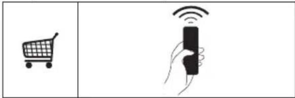
text_image
Diagram showing a shopping cart and a hand holding a remote control with Wi-Fi signal icons6. LIGHTING
- For replacement contact technical support ("To purchase contact technical support").
CE
EN USER MANUAL
DE BENUTZERHANDBUCH
FR MANUEL D'INSTRUCTIONS

text_image
HOB²HOODHob²Hood
It is an advanced automatic function which connects the hob to a special hood. Both the hob and the hood have an infra — red signal communicator.
Speed of the fan is defined automatically on basis of mode setting and temperature of the hottest cookware on the hob. You can also operate the fan from the hob manually.

For most of the hoods the remote system is originally deactivated. Activate it before you use the function.

When you operate the appliance with the function:
- Protect the hood panel from direct sunlight.
- Do not spot halogen light on the hood panel.
- Do not cover the hob panel (eg. Hand or pan handle).
- Using manual controls of a hood, Hob2Hood function is deactivated temporarily. Connection to the hood will be reinitiated automatically with a next signal received from a hob.

| Model of the hood |
| X09481BV-X |
| X86464BV01 |
| DVK7990HB (*) |
| DVK7990HW (*) |
| DVK6980HB (*) |
| DVK6980HW (*) |
| DVK6980DHB (*) |
| WOGL9050CN (*) |
| Model of the hood |
| DVK6680HB |
| DD5960V |
| DD5660V |
| Model of the hood |
| EFV90673OK |
| EFV90673OW |
| EFV819Y |
| EFV819W |
| EFV816W |
| EFV816Y |
| DVB5960HB |
| DVB5960HG |
| GD5960V |
| GD5660V |
| DVB5660HG |
| EFF90670OY |
| ECS9252K |
| DECS6252K |
| DECS9252K |
| Model of the hood |
| WOSL9062CN |
| WOGL9062CN |
text_image
Min.500 Max.700 Min.400 Max.800 Min.450 Max.600 Min.450 Max.600(*) The hob controls only 4 speeds of the hood.
Receiver activation
natural_image
Simple geometric diagram of a T-shaped block with two stacked rectangles (no text or symbols)
natural_image
Simple line drawing of a microwave oven emitting signal waves (no text or symbols)| Model of the hood |
| X09481BV-X |
| X86464BV01 |
| EFV90673OK |
| EFV90673OW |
| EFF90670OY |
| ECS9252K |
| DECS6252K |
| DECS9252K |
| A | B | C | D | E | F | G | H | ||||||
| Button Function Led | |
| G If pressed and held for 5 seconds with the hood and lightturned off and no alarm, do:Enables the Remote control.Disables the Remote control. | 2 Flashes Led button C + B1 Flash Led button C + B |
natural_image
Simple 3D geometric shape resembling a T-shape with two stacked rectangles (no text or symbols)
text_image
A B C D E F G H ① Y₁ Y₂ Y₃ Y₄ F/C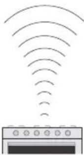
natural_image
Simple line drawing of a microwave oven emitting signal waves (no text or symbols)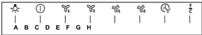
text_image
A B C D E F G H ① ② ③ ④ ⑤ ⑥ ⑦ ⑧ ⑨ ⑩ ⑪ ⑫ ⑬ ⑭ ⑮ ⑯ ⑰ ⑱ ⑲ ⑳ ㉑ ㉒ ㉓ ㉔ ㉕ ㉖ ㉗ ㉘ ㉙ ㉚ ㉛ ㉜ ㉝ ㉞ ㉟ ㉳ ㉟ ㉟ ㉟ ㉟natural_image
Simple geometric diagram of a T-shaped block with two stacked blocks (no text or symbols)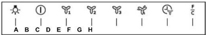
text_image
A B C D E F G H ① 1 2 3 4 F/C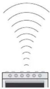
natural_image
Diagram of a microwave oven emitting signal waves (no text or symbols)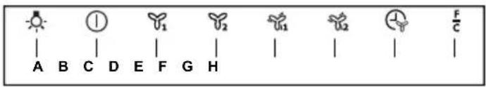
text_image
A B C D E F G H ① ② ③ ④ F/CWarning! Before proceeding with installation, read the safety information in the User Manual.

text_image
Ø 120 mm - Ø 150 mm 1x
text_image
Ø 150 mm 2x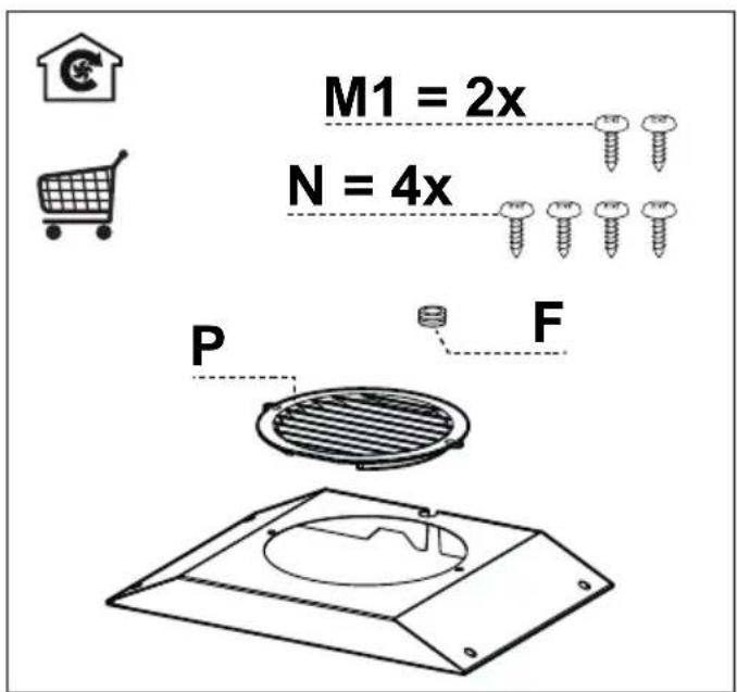
text_image
M1 = 2x N = 4x P F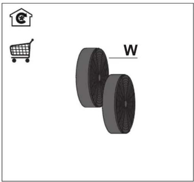
natural_image
Illustration of a shopping cart, a house icon, and two circular wheels labeled 'W' (no text or symbols on the wheels themselves)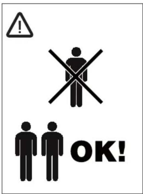
text_image
! OK!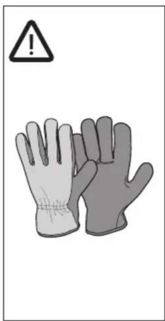
text_image
Warning symbol with warning triangle and two gloves, one labeled with an exclamation mark
text_image
M450 450mm 90° M450 450mm

text_image
415 81 21 126 200 330 Min 455-Max 640 300 379 450 382 440 174 598 - 898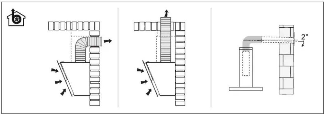
text_image
Technical diagram illustrating three different pipe installation methods with directional arrows and dimension标注 of 2° angle.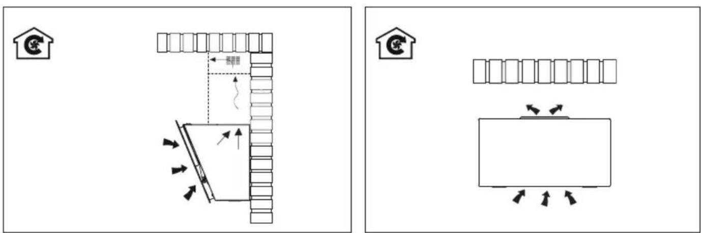
text_image
Diagram showing two layout arrangements with labeled furniture and directional arrows, likely illustrating a home or warehouse layout concept.
text_image
Diagram showing two safety scenarios with warning symbols and directional arrows indicating movement or hazard.
text_image
1 ↑ ↓ 1 = = =2


text_image
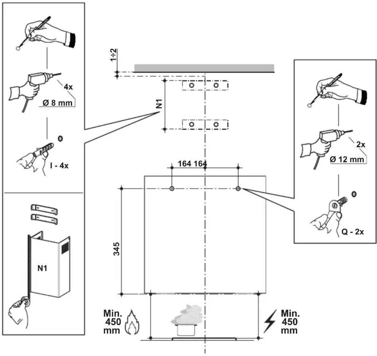
1÷2 Ø 8 mm 1 - 4x N1 164 164 345 Q - 2x Ø 12 mm Min. 450 mm Min. 450 mm
text_image
3 ↑ €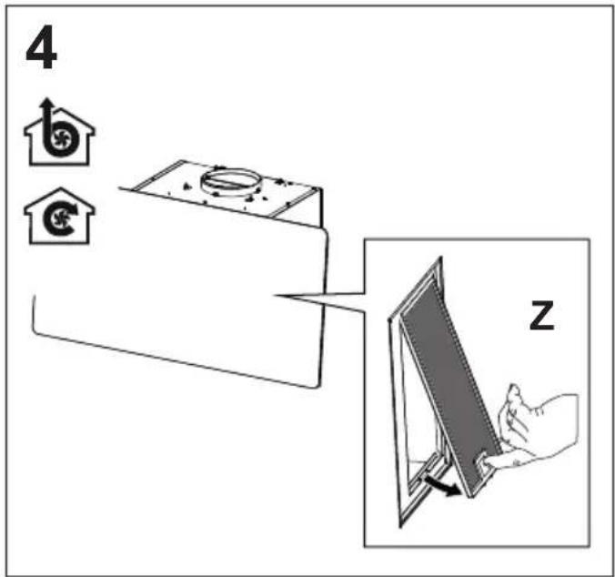
text_image
4 z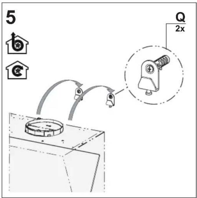
text_image
5 Q 2x
text_image
6 Q 2x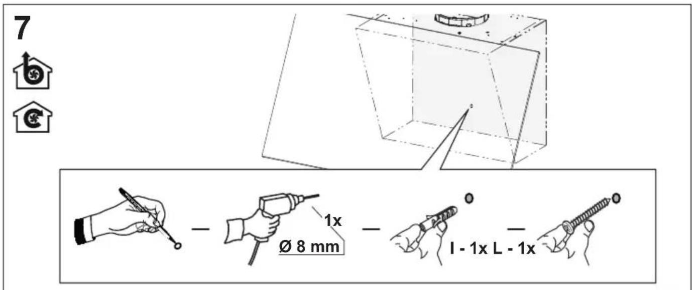
text_image
7 b € Ø 8 mm 1x I - 1x L - 1x8


text_image
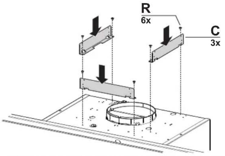
R 6x C 3x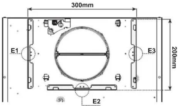
text_image
300mm E1 E3 200mm E2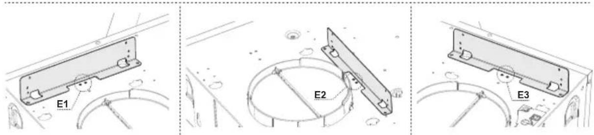
text_image
E1 E2 E39

text_image
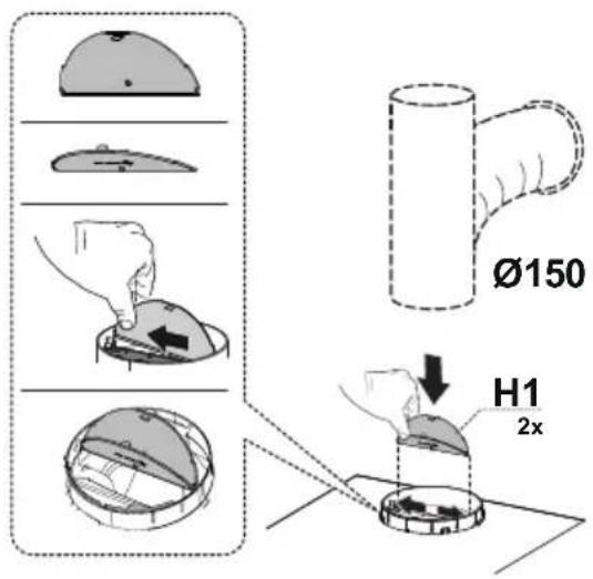
Ø150 H1 2x
text_image
Ø120 O H1 2x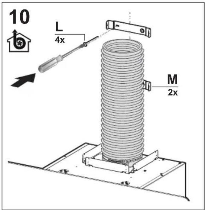
text_image
10 L 4x M 2x
text_image
11 N1
text_image
12 S 4x
text_image
13 N2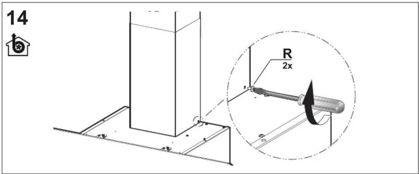
text_image
14 R 2x
text_image
15 M 1x L 2x O2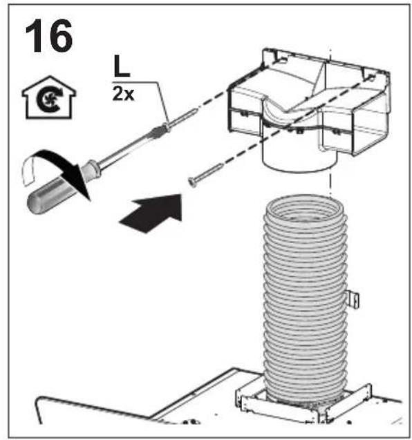
text_image
16 L 2x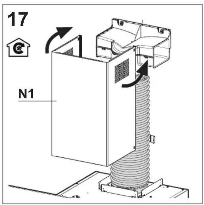
text_image
17 N1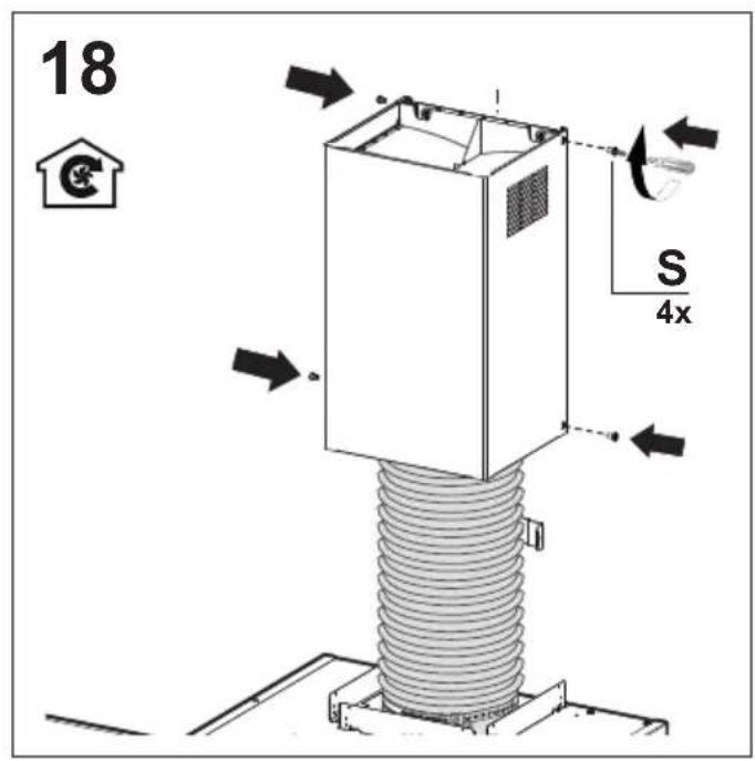
text_image
18 S 4x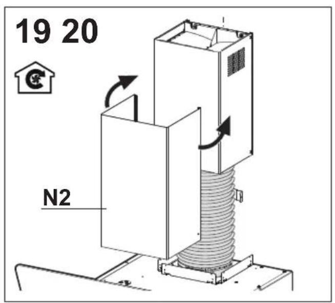
text_image
19 20 N2
text_image
R 2x
flowchart
graph TD
    A["House Icon"] --> B["Process Box"]
    B --> C["Arrow Right"]
    B --> D["Arrow Left"]
    B --> E["Arrow Up"]
    B --> F["Arrow Down"]
    B --> G["Arrow Up again"]
    style A fill:#f9f,stroke:#333
    style B fill:#ccf,stroke:#333
text_image
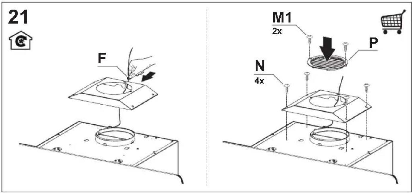
21 F M1 2x P N 4x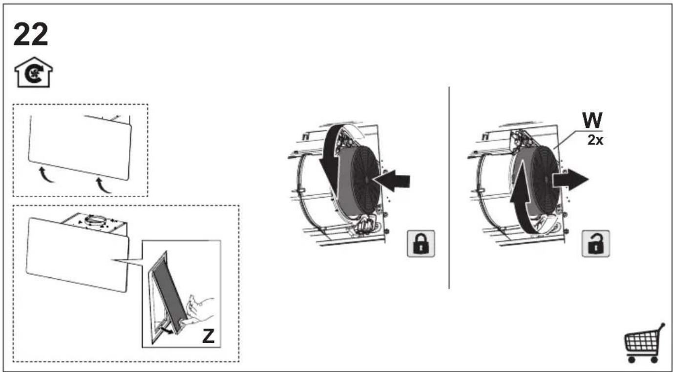
text_image
22 W 2x Z
text_image
Diagram illustrating a door lock operation with icons for home, car, and hand movement, including a magnified view of the lock mechanism.