
XTREEM-WALL - Unspecified Smart-AVI - Free user manual and instructions
Find the device manual for free XTREEM-WALL Smart-AVI in PDF.

| Product Type | 4K Multi-Format Video Wall Controller |
| Brand | Smart-AVI |
| Model | XTREEM-WALL |
| Input Ports | 1 x DisplayPort, 1 x DVI-I, 1 x HDMI |
| Output Ports | 4 x HDMI (1080p), 1 x HDMI Loopback |
| Max Input Resolution | 3840x2160 @ 30Hz |
| Max Output Resolution | 1920x1080 @ 60Hz |
| Supported Video Modes | Full Video Wall, Clone, PIP, POP, Flip |
| Control Methods | Front Panel Buttons, IR Remote, Web Console (TCP/IP) |
| IR Receiver | SM-EYE3 (included) |
| RS-232 | DB9 Female (firmware updates only) |
| Network | RJ45 LAN for TCP/IP control |
| Power Supply | 12VDC 3.33A (included) |
| Dimensions (W x D x H) | 17" x 10.8" x 1.9" |
| Weight | 6.95 lbs (approx. 3.15 kg) |
| Working Temperature | 32°F to 122°F (0°C to 50°C) |
| Storage Temperature | -4°F to 149°F (-20°C to 65°C) |
| Working Humidity | Up to 85% RH (non-condensing) |
| Storage Humidity | Up to 90% RH (non-condensing) |
| Compliance | HDCP Compliant |
| Audio | HDMI Digital Audio |
| Included Accessories | IR Remote, IR Receiver, Power Adapter, Quick Start Guide |
| Applications | Digital Signage, Video Walls, Corporate Presentations, Control Rooms |
| Warranty | 1 Year Limited Warranty |
Frequently Asked Questions - XTREEM-WALL Smart-AVI
User questions about XTREEM-WALL Smart-AVI
0 question about this device. Answer the ones you know or ask your own.
Ask a new question about this device
Download the instructions for your Unspecified in PDF format for free! Find your manual XTREEM-WALL - Smart-AVI and take your electronic device back in hand. On this page are published all the documents necessary for the use of your device. XTREEM-WALL by Smart-AVI.
USER MANUAL XTREEM-WALL Smart-AVI
natural_image
Exterior view of a Smart-MX TREEM-WALL server unit (no visible text or symbols on body)4K INPUT MULTI-FORMAT 2X2 VIDEO WALL CONTROLLER

flowchart
graph TD
    A["HDMI Source"] -->|DVI Source| B["XTREEM-WALL"]
    C["DP Source"] -->|DVI Source| B
    B -->|4K N HD OUT HDMI/DF/DMI Video Wall Controller| D["Smart-AI"]
    B -->|IR EYE Receiver| E["IR Remote Control"]
    B --> F["TCP-IP"]
    B --> G["LAN"]
    H["Local Loopback HDMI Display"] --> I["Computer"]
    J["HDMI Video Wall Output (4)"] --> K["Output 4"]
    L["DP Input"] --> M["Input 1"]
    N["HDMI Output"] --> O["Input 1"]
    P["HDMI Input"] --> Q["Input 1"]
    R["DVI Input"] --> S["Input 1"]
    T["IR Receiver"] --> U["Input 1"]
    V["RJ45"] --> W["Input 1"]
    X["TCP-IP"] --> Y["Remote Control"]
    Z["LAN"] --> AA["Remote Control"]
Smart-AM
SMART AUDIO VIDEO INNOVATION
| TABLE OF CONTENTS | |
| WHAT'S IN THE BOX? 2 | |
| INTRODUCTION | 3 |
| FEATURES | 3 |
| APPLICATIONS 3 | |
| TECHNICAL SPECIFICATIONS | 4 |
| HARDWARE INSTALLATION | 5-6 |
| FRONT PANEL CONTROL | 7 |
| IR REMOTE CONTROL | 8 |
| CONTROL VIA NETWORK 9-14 | |
| PRE-DEFINED DISPLAY MODES | 15 |
| LIMITED WARRANTY STATEMENT 16 | |
WHAT'S IN THE BOX?
| PART NO. QTY DESCRIPTION | ||
| XTRW-S | 1 | 4K IN-HD OUT HDMI/DP/DVI-I Video Wall Controller |
| RMT-XW 1 IR Remote Control | ||
| SM-EYE3 1 IR Receiver | ||
| PS12VDC3.33A 1 Power Adapter | ||
| 1 Quick Start Guide | ||
Brackets for mounting this device in a standard 19" rack can be ordered from SmartAVI.

Figure 2-1
INTRODUCTION
The XTREEM-WALL is Smart-AVI's easiest and most effective solution for building creatively configured video walls. With multi-format inputs for video resolutions up to 4K (3840x2160 @ 30Hz), the XTREEM-WALL sends multi-screen imagery to four connected HDMI displays in 1080p Full HD (1920x1080 @ 60Hz) output.
Best of all, the XTREEM-WALL is highly compatible with the most popular displays on the market, and features a wide variety of video wall modes.
FEATURES
- INPUT: (1) DP, (1) DVI-I Full HD Input, (1) HDMI 4K Input
• OUTPUT: (4) 1080p HDMI, (1) HDMI Local Loop - Input up to 4K (3840x2160 @ 30Hz)
• Output up to 1080p (1920x1080 @ 60Hz) - Creative configuration modes, including: Full Video Wall | Clone | PIP | POP | Flip
• Supports VGA & Y/Pb/Pr (With DVI-I Adapter)
• Supports IR remote control
• Control over web console - Plug-and-Play ready
- Front Panel Buttons: XTREEM-WALL features a button control panel for switching between sources and accessing preset configurations.
- Web Console: Control everything from source resolution and aspect ratios to creative display modes from anywhere in the world over the Internet with SmartAVI's easy-to-use web console for the XTREEM-WALL.
APPLICATIONS
• Corporate or Educational Presentations
- Airport Installations
- Wall Displays
- Digital Signage
- Dealer Rooms
- Control Rooms
- Shopping Centers
- Security
- Point-of-Sale
- Entertainment Venues
• Corporate Lobbies
- Restaurants
TECHNICAL SPECIFICATIONS
| VIDEO (and AUDIO) | |
| Video Format DP, DVI-I, HDMI | |
| Video Input (1) DP; (1) DVI-I; (1) HDMI, VGA & Y/Pb/Pr support w/ DVI-I adaptor | |
| Video Output (4) HDMI 2.0 (1) HDMI Loopback | |
| Input Resolution Up to 4K (3840x2160 @ 30Hz) | |
| Output Resolution Up to 1080 (1920x1080 @ 60Hz) | |
| Audio Input/Output HDMI Digital Audio | |
| Compliance HDCP Compliant | |
| CONTROL | |
| Front Panel Buttons | |
| TCP/IP | Web Console |
| IR Remote Control | RC-100 Infrared Remote Control with IR-EYE3 receiver |
| OTHER | |
| RS-232 DB9 Female, 115200 bps, N, 8 1, No flow control (For firmware updates only) | |
| Power Adapter 12VDC 3.33A | |
| Weight 6.95 lbs. | |
| Dimensions 17"W X | 10.8"D X 1.9"H |
| Working Temp. 32 to 122°F (0 to 50 °C) | |
| Working Humidity Up to 85% RH (no condensation) | |
| Storage Temp. -4 to 149 °F (-20 to 65 °C) | |
| Storage Humidity Up to 90% RH (no condensation) | |
HARDWARE INSTALLATION
- Make sure the XTREEM-WALL is turned off.
- Connect up to 3 inputs or sources. (1 DP, 1 HDMI, 1 DVI)
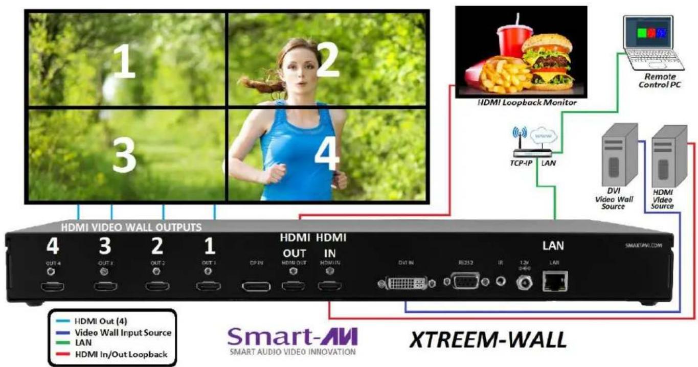
- Connect up to 4 displays to the HDMI OUTPUT ports on the XTREEM-WALL. See Figure 5-2 for display locations.
- Optionally connect a display to the HDMI OUT (Loopback) port.
- Optionally connect the IR receiver to the IR input jack on the back of the XTREEM-WALL.
- Optionally connect a network with a cat5/6 cable to the RJ45 LAN connector on the back of the XTREEM-WALL.
- Turn on the XTREEM-WALL.
- Wait for the unit to initialize.
NOTE: The RS-232 port on the back of the XTREEM-WALL is for firmware updates only.

flowchart
graph TD
    A["HDMI Video Wall Output (4)"] --> B["DVI Source"]
    C["DP Input"] --> D["DP Source"]
    E["HDMI Output (1)"] --> F["IR EYE Receiver"]
    G["HDMI Input"] --> H["IR Receiver"]
    I["DVI Input"] --> J["IR Remote Control"]
    K["IR Receiver"] --> L["IR Remote Control"]
    M["RJ4S"] --> N["XTREEM-WALL"]
    O["Local Loopback HDMI Display"] --> P["Smart-AI"]
    Q["TCP-IP"] --> R["LAN"]
    S["Remote Control"] --> T["Smart Audio Video Innovation"]
    U["4KON-RD OUT HDMI/DP HDMI VideoWall Controller"] --> V["XTREEM-WALL"]
    W["IR EYE Receiver"] --> X["XTREEM-WALL"]
Figure 5-1

Connect HDMI Output port 1 to the upper left display. Connect HDMI Output port 2 to the upper right display. Connect HDMI Output port 3 to the lower left display. Connect HDMI Output port 4 to the lower right display.
Figure 5-2

Figure 5-3
HARDWARE INSTALLATION (Continued)
Figure 6-1 below shows a configuration using an HDMI source to display a video wall plus an additional display using the HDMI Out loopback port.

flowchart
graph TD
    A["Smart-AVI SMART AUDIO VIDEO INNOVATION"] --> B["Outdoor Media"]
    B --> C["Local HDMI Loopback Monitor"]
    C --> D["Remote Control PC"]
    D --> E["Video Wall Source"]
    E --> F["Smart TV Wall"]
    subgraph Smart-AVI
        G["OUT 4"] --> H["OUT 3"] --> I["OUT 2"] --> J["OUT 1"] --> K["OUT IN"] --> L["HDMI OUT"] --> M["HDMI IN"] --> N["OUT SN"] --> O["RS212"] --> P["12V"] --> Q["LAN"]
    end
    subgraph XTREEM-WALL
        R["LAN"] --> S["Smart TV Wall"]
    end
    G --> T["Out 4"]
    H --> U["OUT 3"]
    I --> V["OUT 2"]
    J --> W["OUT 1"]
    K --> X["OUT IN"]
    L --> Y["OUT SN"]
    M --> Z["RS212"]
    P --> AA["12V"] --> AB["LAN"]
    Q --> AC["LAN"]
    R --> AD["Out 4"]
    S --> AE["Out 3"]
    T --> AF["Out 2"]
    U --> AG["Out 1"]
    V --> AH["Out IN"]
    W --> AI["Out SN"]
    X --> AJ["RS212"]
    Y --> AK["12V"] --> AL["LAN"]
    Z --> AM["LAN"]
    AA --> AN["LAN"]
    AB --> AO["LAN"]
    AC --> AP["LAN"]
    AD --> AQ["Out 4"]
    AE --> AR["Out 3"]
    AF --> AS["Out 2"]
    AG --> AT["Out 1"]
    AH --> AU["Out IN"]
    AI --> AV["Out SN"]
    AJ --> AW["RS212"]
    AK --> AX["12V"] --> AY["LAN"]
    AL --> AZ["LAN"]
    AM --> BA["LAN"]
    AN --> BB["LAN"]
    AO --> BC["LAN"]
    AP --> BD["LAN"]
    AQ --> BE["LAN"]
    AR --> BF["LAN"]
    AS --> BG["LAN"]
    AT --> BH["LAN"]
    AU --> BI["LAN"]
    AV --> BJ["LAN"]
    AW --> BK["LAN"]
    AX --> BL["LAN"]
    AY --> BM["Out 4"]
    AZ --> BN["Out 3"]
    BA --> BO["Out 2"]
    BB --> BP["Out 1"]
    BC --> BQ["Out IN"]
    AD --> BR["Out SN"]
    AE --> BS["RS212"] --> BT["12V"] --> BU["LAN"]
    AC --> BV["LAN"]
    AD --> BW["LAN"]
    AE --> BX["LAN"]
    AF --> BY["LAN"]
    AG --> BZ["LAN"]
    AH --> CA["LAN"]
    AI --> CB["LAN"]
    AJ --> CC["LAN"]
    AK --> CD["LAN"]
    AL --> CE["LAN"]
    AM --> CF["LAN"]
Figure 6-1
Figure 6-2 below shows a configuration using a DVI input for the video wall while using the HDMI loop-back ports to connect an additional display.
flowchart
graph TD
    A["Smart-AVI SMART AUDIO VIDEO INNOVATION"] --> B["4 OUT 4"]
    A --> C["3 OUT 3"]
    A --> D["2 OUT 2"]
    A --> E["1 OUT 1"]
    A --> F["HDMI OUT (4)"]
    A --> G["Video Wall Input Source"]
    A --> H["LAN"]
    A --> I["HDMI In/Out Loopback"]
    J["XTREEM-WALL"] --> K["LAN"]
    L["HDMI Video Wall OUTPUTS"] --> M["OUT 4"]
    L --> N["OUT 3"]
    L --> O["OUT 2"]
    L --> P["OUT 1"]
    L --> Q["CP IN"]
    L --> R["HDMI OUT"]
    L --> S["HDMI IN"]
    L --> T["DUI IN"]
    L --> U["RU352"]
    L --> V["IR"]
    L --> W["LW 2.4W"]
    L --> X["LAN"]
    Y["HDMI Loopback Monitor"] --> Z["TCP-IP LAN"]
    AA["Remote Control PC"] --> AB["DVI Video Wall Source"]
    AA --> AC["HDMI Video Source"]
Figure 6-2
FRONT PANEL CONTROL
To switch between listed sources, press:
- DVI
- HDMI
- DisplayPort
To switch to Video Wall mode, press the WALL button.
To switch to Clone mode, press the CLONE button.

Loading predefined display modes. First press the MACRO button. Then press:

4 =

natural_image
Two side-by-side photos of a tall conifer tree with visible roots and surrounding trees under a blue sky (no text or symbols)5 = Standard video wall. Same as WALL button.
VIDEO WALL MODE

natural_image
Woman jogging in a green park with blurred trees and a path (no text or symbols visible)An Image can be displayed across four HD screens 2X2.
Figure 6-1
CLONE MODE

natural_image
Four-panel sequence of a woman jogging in a park with green foliage, no text or symbols visibleThe image can be dis-
played on each display in-
dividually.
Figure 6-2
| IR REMOTE CONTROL | |
| BUTTON | DESCRIPTION |
| HDMI Select HDMI input port | |
| DVI Select DVI input port | |
| DP Select DP input port | |
| Info Current settings will display | |
| MENU Turns on OSD (On Screen Display) | |
| Back Moves back 1 menu | |
| Exit Exit OSD | |
| ▲ OSD (On Screen Display) Navigation | |
| ▼ | OSD (On Screen Display) Navigation |
| ◀ | OSD (On Screen Display) Navigation |
| ▶ | OSD (On Screen Display) Navigation |
| OK Executes selection or opens menu | |
| OTH Opens selected Menu | |
| OSD TIME OUT | Sets time before OSD turns off |
| VIDEO WALL | Opens OSD for output settings |

CONTROL VIA NETWORK
XTREEM-WALL TCP/IP control is a feature that allows mode switching and other configurations to be controlled remotely via HTTP. Manage your XTREEM-WALL with ease from anywhere in the world.
First you must find the IP address for the XTREEM-WALL . Finder.exe (Smart IP-Finder) is conveniently available on our website; please visit www.smartavi.com/helpful-links.html for this and our full list of compatible third-party software. Download and execute the IP address Finder software for your product. The XTREEM-WALL and its IP address should appear in the display as shown in Figure 9-1.

Figure 9-1
Enter the IP address into a web browser of your choice. You should see the XTREEM-WALL LOG-IN page as shown in Figure 9-2. The default username is ADMIN and the default password is PASS.
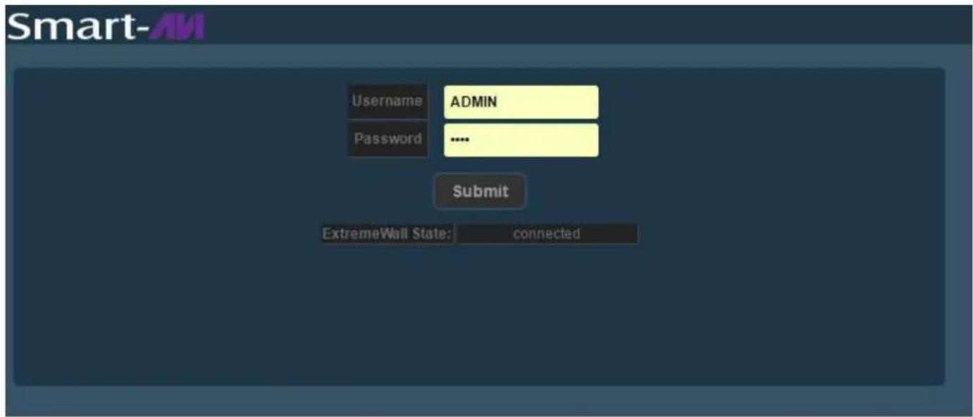
Figure 9-2
CONTROL VIA NETWORK (Continued)

Click the "XTREEM-Wall" tab in the top row and then click the "Current" tab in the second row to see the current status of the XTREEM-WALL.

Click the "XTREEM-Wall" tab in the top row and then click the "Video Wall" tab in the second row. Here you can select the source port for your video wall display.

natural_image
Woman in white shirt using laptop with digital world map background (no text or symbols)
Click the "XTREEM-Wall" tab in the top row and then click the "Video Wall Clone" tab in the second row. Here you can select the source port for your video wall display.

natural_image
Four-panel image showing a woman in a white shirt using a laptop, with a world map background (no text or symbols)CONTROL VIA NETWORK (Continued)

Click the "XTREEM-Wall" tab in the top row and then click the "Video Wall Flip" tab in the second row. Here you can select the source port for your video wall display.

Figure 11-1

Figure 11-3
Why Video Wall Flip?
Many HDTV displays have a bezel that is wider on the bottom than it is on the top and sides as shown in figure 11-1. The Video Wall flip feature fixes this by allowing you to flip the top two displays in your video wall 180 degrees so the wide edges are on the outside of your video wall as shown in figure 11-2. Now select your source on the Video Wall Flip page and the video output to the top two displays will rotate 180 degrees as shown in figure 11-3.

Figure 11-2
CONTROL VIA NETWORK (Continued)

Click the "XTREEM-Wall" tab in the top row and then click the "PiP" tab in the second row. Here you can select the source port (Master) for your video wall and the PiP port (Slave) that will appear smaller and center screen.

natural_image
Autumn park scene with vibrant red and orange trees and a person walking (no text or symbols)
Click the "XTREEM-Wall" tab in the top row and then click the "PiP Clone" tab in the second row. Here you can select the source port (Master) for the background image on each display and the PiP port (Slave) that will appear smaller and centered in each display.

natural_image
Sequence of five photos showing a woman in a blue tank top standing on a tree with vibrant orange and green foliage, no text or symbols visible.CONTROL VIA NETWORK (Continued)

Click the "XTREEM-Wall" tab in the top row and then click the "PiP Flip" tab in the second row. Here you can select the source port (Master) for your video wall and the PiP port (Slave) that will appear smaller and center screen.

natural_image
Four-panel image showing autumn trees with vibrant red and orange foliage, plus a person in a blue jacket on a tree (no text or symbols)Figure 13-1

natural_image
Four-panel comparison of autumn trees under different image conditions: Smart-AVI, Smart-AVI, and a person in a blue jacket.Figure 13-3
Why PiP Flip?
Many HDTV displays have a bezel that is wider on the bottom than it is on the top and sides as shown in figure 13-1. The Video Wall flip feature fixes this by allowing you to flip the top two displays in your video wall 180 degrees so the wide edges are on the outside of your video wall as shown in figure 13-2. Now select your source on the Video Wall Flip page and the video output to the top two displays will rotate 180 degrees as shown in figure 13-3.

natural_image
Four-panel image grid showing autumn trees with vibrant red and orange foliage, labeled Smart-AVI and Smart-AVII (no text or symbols in the images themselves)Figure 13-2
CONTROL VIA NETWORK (Continued)

Click the "XTREEM-Wall" tab in the top row and then click the "PoP" tab in the second row. Here you can select the source port for the left 2 displays and the source port for the right 2 displays.

natural_image
Close-up of a hamburger with cheese, fried fries, and a red cup against black background (no text or symbols)
The XTREEM-WALL's PoP feature creates 2 separate displays from 2 sources with 2 stacked monitors per display. The Input sources are sent to the output ports as shown in Figure 14-1.


Figure 14-1
PRE-DEFINED DISPLAY MODES

Figure 15-1
The XTREEM-WALL has several pre-defined display modes accessible with the remote control and on screen menus.

2x2 with clockwise 15 degree rotation and TV2 & TV4 shifted up 1/2 panel height (Ratio 1.7)
Figure 15-2

2x2 with TV2 & TV4 shifted down 1/2 panel height (Ratio 1.42)
Figure 15-3
LIMITED WARRANTY STATEMENT
A. Extent of limited warranty
Smart-AVI Technologies, Inc. warrants to the end-user customers that the Smart-AVI product specified above will be free from defects in materials and workmanship for the duration of 1 year, which duration begins on the date of purchase by the customer. Customer is responsible for maintaining proof of date of purchase.
Smart-AVI limited warranty covers only those defects which arise as a result of normal use of the product, and do not apply to any:
a. Improper or inadequate maintenance or modifications
b. Operations outside product specifications
c. Mechanical abuse and exposure to severe conditions
If Smart-AVI receives, during applicable warranty period, a notice of defect, Smart-AVI will at its discretion replace or repair defective product. If Smart-AVI is unable to replace or repair defective product covered by the Smart-AVI warranty within reasonable period of time, Smart-AVI shall refund the cost of the product.
Smart-AVI shall have no obligation to repair, replace or refund unit until customer returns defective product to Smart-AVI.
Any replacement product could be new or like new, provided that it has functionality at least equal to that of the product being replaced.
Smart-AVI limited warranty is valid in any country where the covered product is distributed by Smart-AVI.
B. Limitations of warranty
To the extant allowed by local law, neither Smart-AVI nor its third party suppliers make any other warranty or condition of any kind whether expressed or implied with respect to the Smart-AVI product, and specifically disclaim implied warranties or conditions of merchantability, satisfactory quality, and fitness for a particular purpose.
C. Limitations of liability
To the extent allowed by local law the remedies provided in this warranty statement are the customers sole and exclusive remedies.
To the extant allowed by local law, except for the obligations specifically set forth in this warranty statement, in no event will Smart-AVI or its third party suppliers be liable for direct, indirect, special, incidental, or consequential damages whether based on contract, tort or any other legal theory and whether advised of the possibility of such damages.
D. Local law
To the extent that this warranty statement is inconsistent with local law, this warranty statement shall be considered modified to be consistent with such law.
Smart-AMI
SMART AUDIO VIDEO INNOVATION
NOTICE
The information contained in this document is subject to change without notice. SmartAVI makes no warranty of any kind with regard to this material, including but not limited to, implied warranties of merchantability and fitness for particular purpose. SmartAVI will not be liable for errors contained herein or for incidental or consequential damages in connection with the furnishing, performance or use of this material. No part of this document may be photocopied, reproduced, or translated into another language without prior written consent from SmartAVI Technologies, Inc.
20170425

Designed and Manufactured in the USA
800.AVI.2131
Tel: (818) 503-6200 | Fax: (818) 503-6208 11651 Vanowen St. North Hollywood, CA 91605
SmartAVI.com


- INTRODUCTION
- FEATURES
- APPLICATIONS
- HARDWARE INSTALLATION
- HARDWARE INSTALLATION (Continued)
- FRONT PANEL CONTROL
- CONTROL VIA NETWORK
- CONTROL VIA NETWORK (Continued)
- Why Video Wall Flip?
- Why PiP Flip?
- PRE-DEFINED DISPLAY MODES
- LIMITED WARRANTY STATEMENT
- Extent of limited warranty
- Limitations of warranty
- Limitations of liability
- Local law
- Smart-AMI
- SMART AUDIO VIDEO INNOVATION
- NOTICE
Brand : Smart-AVI
Model : XTREEM-WALL
Category : Unspecified