
M2T-X - Unspecified Lectrosonics - Free user manual and instructions
Find the device manual for free M2T-X Lectrosonics in PDF.

| Product Type | Digital half-rack wireless IEM transmitter with Dante network audio |
| Model | M2T-X (A1B1 band) |
| RF Power Output | 10, 25, or 50 mW per carrier (two carriers) |
| Frequency Range (A1B1) | 470.100 – 607.975 MHz |
| Frequency Selection Steps | 25 kHz |
| Modulation | 8 PSK |
| Encryption | AES 256 bit CTR mode (with v3.X firmware); key types: Universal, Shared, Standard, Volatile |
| Audio Inputs | 4 x combo XLR/TRS (analog or Dante digital) |
| Audio Frequency Response | 10 Hz – 11.5 kHz, -1 dB |
| Latency (Analog Source) | < 1.8 ms |
| Latency (Digital Source) | 1.0 ms plus Dante network |
| Equivalent Input Noise | -128 dBV |
| Antenna Output | 2 x BNC (50 ohm) |
| Dante Ports | 2 x RJ45 (optional card) |
| Ethernet Port | RJ45 for control and monitoring |
| USB Port | Micro USB (firmware updates) |
| IR Port | For syncing settings with receivers |
| Headphone Jack | 3.5 mm stereo |
| Power Requirements | 9-18 VDC (1.2A max) |
| Power Consumption | 11 Watts |
| Dimensions (H x W x D) | 1.75 x 8.375 x 7.75 in (44.45 x 212.7 x 196.8 mm) |
| Weight | 2.2 lbs (997.9 g) |
| Operating Temperature | -20°C to 40°C (-5°F to 104°F) |
| Compatibility Modes | Duet (unencrypted) and DCHX (encrypted) |
| Included Accessories | Power supply (DCR15/4AU), USB cable, antennas, rack mount hardware, hex key |
Frequently Asked Questions - M2T-X Lectrosonics
User questions about M2T-X Lectrosonics
0 question about this device. Answer the ones you know or ask your own.
Ask a new question about this device
Download the instructions for your Unspecified in PDF format for free! Find your manual M2T-X - Lectrosonics and take your electronic device back in hand. On this page are published all the documents necessary for the use of your device. M2T-X by Lectrosonics.
USER MANUAL M2T-X Lectrosonics
Dante ^* is a trademark of Audinate Pty Ltd.
Follow Us On:


Fill in for your records:
Serial Number:
Purchase Date:


SONICS®
Rio Rancho, NM, USA www.lectrosonics.com
Table of Contents
Introduction......4
What is Dante?......4
System Setup Procedures....5
Summary of Steps 5
Panels and Features....6
M2T, M2T/E01, M2T/E02, M2T/E06 Front Panel 6
M2T, M2T/E01, M2T/E02, M2T/E06 Back Panel......6
Operating Instructions 7
IR (infrared) Port....7
USB Port 7
Headphone Volume Adjustment....7
Dante Ports (optional)....7
Ethernet Port....7
Power Inlet 7
Quick Sync 7
Navigating the Menus....7
LCD Menu Map....8
Menu Item Descriptions....9
RF Setup 9
RF Enable/Level....9
Frequency 9
Sync Scan 9
Audio Setup 10
Audio Level/Trim (Audio Input Gain) 10
Audio Input Type....10
Audio Polarity....10
Headphone Monitor....10
IR Sync 10
Sync Settings....10
Sync Flexlist Profile 10
System Settings....10
Front Panel Setup 10
Network Settings 10
Edit Names....10
Restore Defaults 11
About....11
Accessories 12
Hardware Installation....13
Unpacking the Unit 13
Items Included in the Box:....13
Installing two M2T, M2T/E01, M2T/E02, M2T/E06
transmitters into a Single Rack Space....14
Installing One M2T into a Single Rack....16
Installing One DSQD into a Single Rack....16
Mounting M2T to DSQD 18
Wireless Designer Software 20
Firmware Update Instructions.... 20
Specifications and Features....20
Service and Repair 21
Returning Units for Repair....21
Introduction
The M2T Digital Half-Rack Transmitter with analog and digital Dante ^™ network audio inputs presents an excellent sounding IEM system with a unique level of performance in a wireless in-ear monitor system. With ultra-low latency, digital RF modulation and two stereo digital channels, the Duet System provides a truly unique IEM product for demanding, professional applications.
The M2T includes a front-panel USB port for firmware updates and an IR port for fast setup. A large, high resolution, backlit LCD and large membrane switches provide an intuitive interface that is highly visible in daylight or dimly lit conditions.
The half-rack transmitter provides four audio inputs which can be individually configured to be analog or Dante compatible. The input connectors are full size XLR/TRS combo types for balanced line level analog signals. Input preamp circuits use a special balanced amplifier with very high common mode rejection to minimize hum and noise. Analog signals are converted to an internal digital format which is then encoded, organized into packets, and passed to an RF modulator. The modulated RF signal is filtered before and after amplification to suppress out-of-band noise and spurious signals.
Conventional in-ear wireless monitor systems rely on decades-old technology: FM transmission with multiplexed, companded audio. The Duet system employs unique technology to provide ruler-flat frequency response from 20 Hz to 11.5 kHz and maximum channel separation. In addition, the digital audio eliminates a compandor and the associated artifacts. The result is crystal clear sound and extremely low distortion of <0.15%.
In today's world, signal encryption is becoming ever more important. The Duet systems offers both un-encrypted (Duet compat mode) and encrypted (DCHX compat mode) audio encoding. By selecting the DCHX compat mode in your M2Ra, the Duet system offers AES 256 Bit encryption with four different key policies, giving you a wide range of tools for information security.
The M2T is designed and developed with the professional touring, installation, theater and broadcast customers in mind. The transmitter chassis is all-metal. The front panel is an aluminum extrusion with a durable powder coat finish.
What is Dante?
Audinate's patent pending Dante™ technology is a flexible Internet Protocol (IP) and Ethernet based digital AV network technology that eliminates the many bulky cables needed to provide point-to-point wiring for analog AV installations.
With Dante, existing infrastructure can be used for high performance audio as well as for ordinary control, monitoring or business data traffic. Digital networks utilize standard IP over Ethernet offering high bandwidth capable of transporting hundreds of high quality channels over Gigabit Ethernet.
Set-up and configuring the system is made easy as well, saving enormous installation costs and long term cost of ownership on a digital network. The physical connecting point is irrelevant: audio signals can be made available anywhere and everywhere. Patching and routing now become logical functions configured in software, not via physical wired links.
Summary of Dante Benefits
- Plug-and-play technology – automatic discovery and simple signal routing
- Reduced Cost & Complexity- No special skills required to set up audio networking
• Sample accurate playback synchronization - Add/remove/rearrange components at will
• Deterministic latency throughout the network - Support mixed bit depths and mixed sample rates over one network
- Scalable, flexible network topology supporting a large number of senders and receivers
• Supports 1Gbps networks
• Supports a single integrated network for audio, video, control, monitoring - Uses inexpensive, off-the-shelf computer networking equipment
Encryption
The encryption system in Lectrosonics Digital modes D2, DCHX, and HDM may be configured in four different ways, determined by a parameter known as the Key Type. The four key types range from least secure but most convenient, to most secure but least convenient. Below are descriptions of the four Key Types and how they work.
- Universal: This is the default key type, the simplest to use, and the least secure. While encryption is technically being performed and a scanner or simple demodulator would not reveal the signal content, communications are not truly secure. This is because all Lectrosonics products employing the Universal key type use this same “universal” encryption key. With this key type selected, keys do not need to be created or exchanged, and wireless devices can be used without attention to the encryption feature.
- Shared: This is the easiest encryption mode to use while employing a uniquely generated key. This key type offers excellent security and considerable flexibility. Once a key has been created, it can be shared an unlimited number of times with any compatible device which, in turn, can also share the key. This is especially useful when multiple receivers may need to pick up various transmitters.
- Standard: The Standard key type offers enhanced security, at the cost of some complexity. Standard keys are “instance controlled”, which allows the hardware to protect against “differential attacks”. A Standard key can only be sent by the device that created it, and only up to 256 times. Unlike with Shared keys, devices receiving a Standard key cannot pass it on.
- Volatile: The Volatile key type is the most secure, and also the least convenient to use. Volatile keys behave identically to Standard keys, except that they are never stored. Equipment which is turned off while using a Volatile key will come back on with no key. If a key-generating device is left on, the key can be re-shared with units in the system that have lost their keys. Once all equipment having used a given Volatile key is powered off, that key is effectively destroyed. This may be required in some highly secure installations.
System Setup Procedures
Summary of Steps
1) Connect power using supplied DCR15/4AU power supply.
2) Power receiver and scan RF spectrum on site.
3) Sync Scan to transfer information from receiver to transmitter.
4) Tune transmitter to unoccupied channels in scan.
5) Sync receiver (refer to receiver manual).
6) Turn on transmitter RF.
7) Send audio sources to transmitter.
Panels and Features
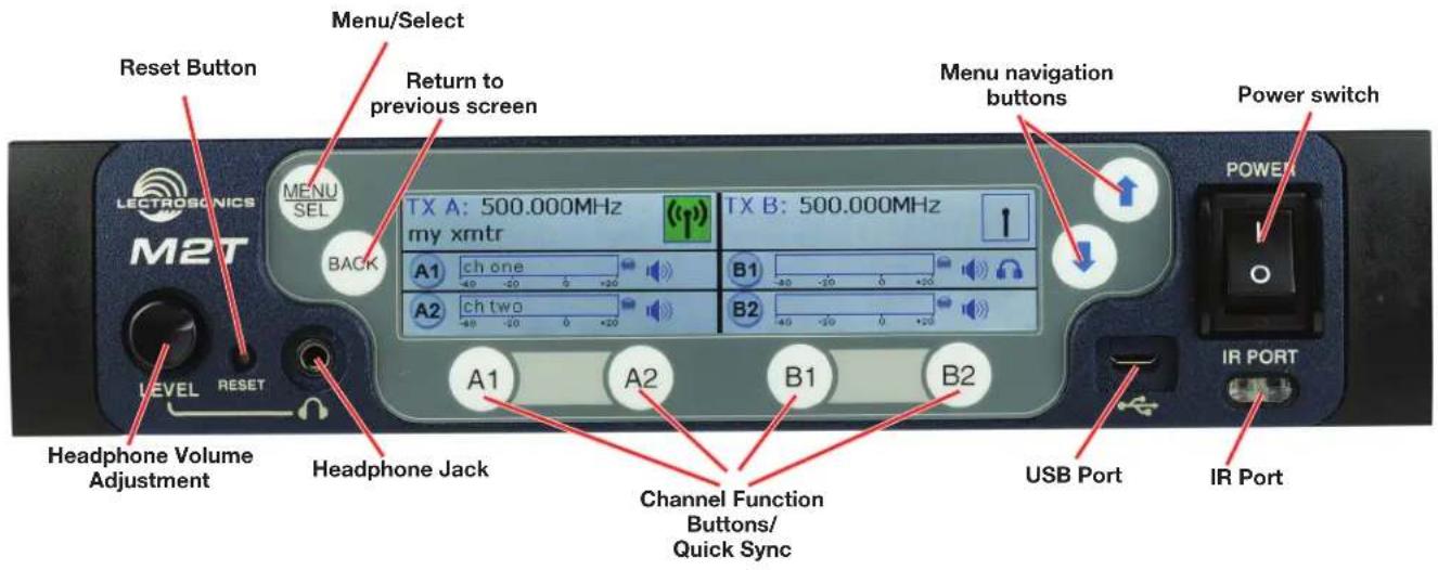
M2T, M2T/E01, M2T/E02, M2T/E06 Front Panel
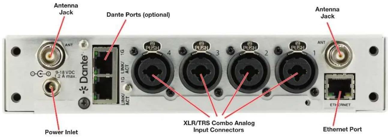
M2T, M2T/E01, M2T/E02, M2T/E06 Back Panel
Operating Instructions
IR (infrared) Port
Settings, including frequency, name, limiter, mix mode, etc. can be transferred to and from the M2T, M2T/E01, M2T/E02, M2T/E06 transmitter via this port to an IR enabled receiver to simplify setup.
USB Port
For firmware updates and connection to Wireless Designer Software.
Reset Button
For MCU recovery in the event of an interrupted firmware update.
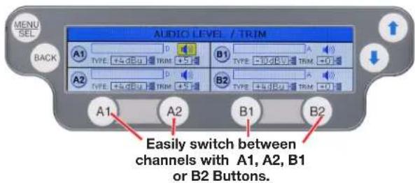
Headphone Volume Adjustment
Adjust the headphone volume, and select source with A1, A2, B1, B2 buttons.
Antenna Output Jacks
Two standard 50 ohm BNC connectors can be used with whip antennas or coaxial cable connected to remote antennas.
Dante Ports (optional)
A Dante Digital Audio Network Interface.
Ethernet Port
Used for setup, monitoring and control with Wireless Designer Software.
Power Inlet
The threaded-locking DC coaxial jack accepts 9-18 VDC and draws 1.2A maximum.
Quick Sync
Sync an M2R or M2Ra rapidly by utilizing the Channel Function Buttons. A long (1 second) press of one of the buttons (A1, A2, B1, or B2) on the front panel initiates Quick Sync. Two options are available, "SYNC ALL" or "SPLIT MONO". The mode is selected prior to sync in System Settings> Front Panel Setup.
NOTE: See Front Panel Setup for more instruction on the Quick Sync function.
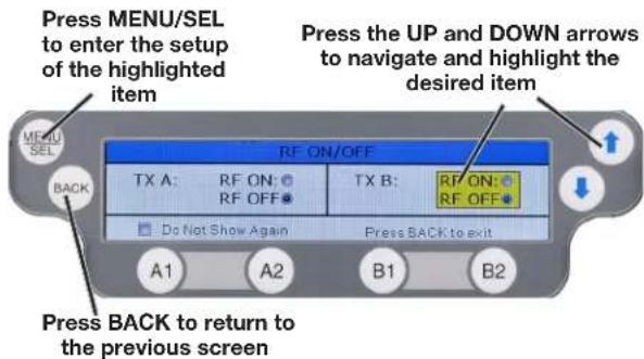
Power Screens
When powering on the M2T there are three screens that appear in the following order, Duet (showing firmware versions), the Lectrosonics logo, and RF On/Off:
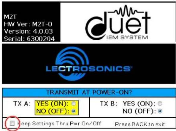
Simultaneous long press of A1/A2 (TX A) or B1/B2 (TX B) will also enable or disable RF.
WARNING: If RF ON is selected and the user chooses to "Do Not Show Again" RF transmissions will be on when the M2T is powered on and may interfere with frequencies already in use. This can be reset in System Settings> FRONT PANEL SETUP.
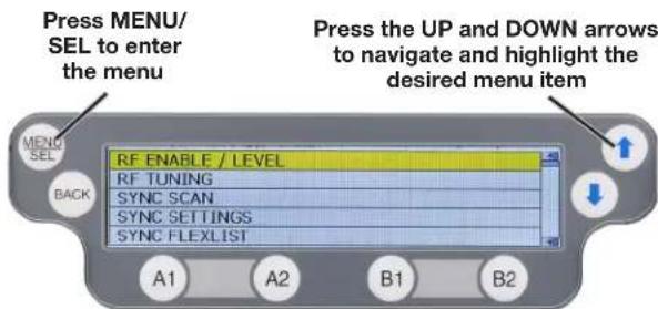
Navigating the Menus
All Menu setup items are arranged in a vertical list on the LCD. Press MENU/SEL to enter the menu, then navigate with the UP and DOWN arrows to highlight the desired setup item. Refer to the menu map on the following page.
NOTE: To guarantee chosen parameters are saved, exit a setup screen BEFORE powering down the M2T.
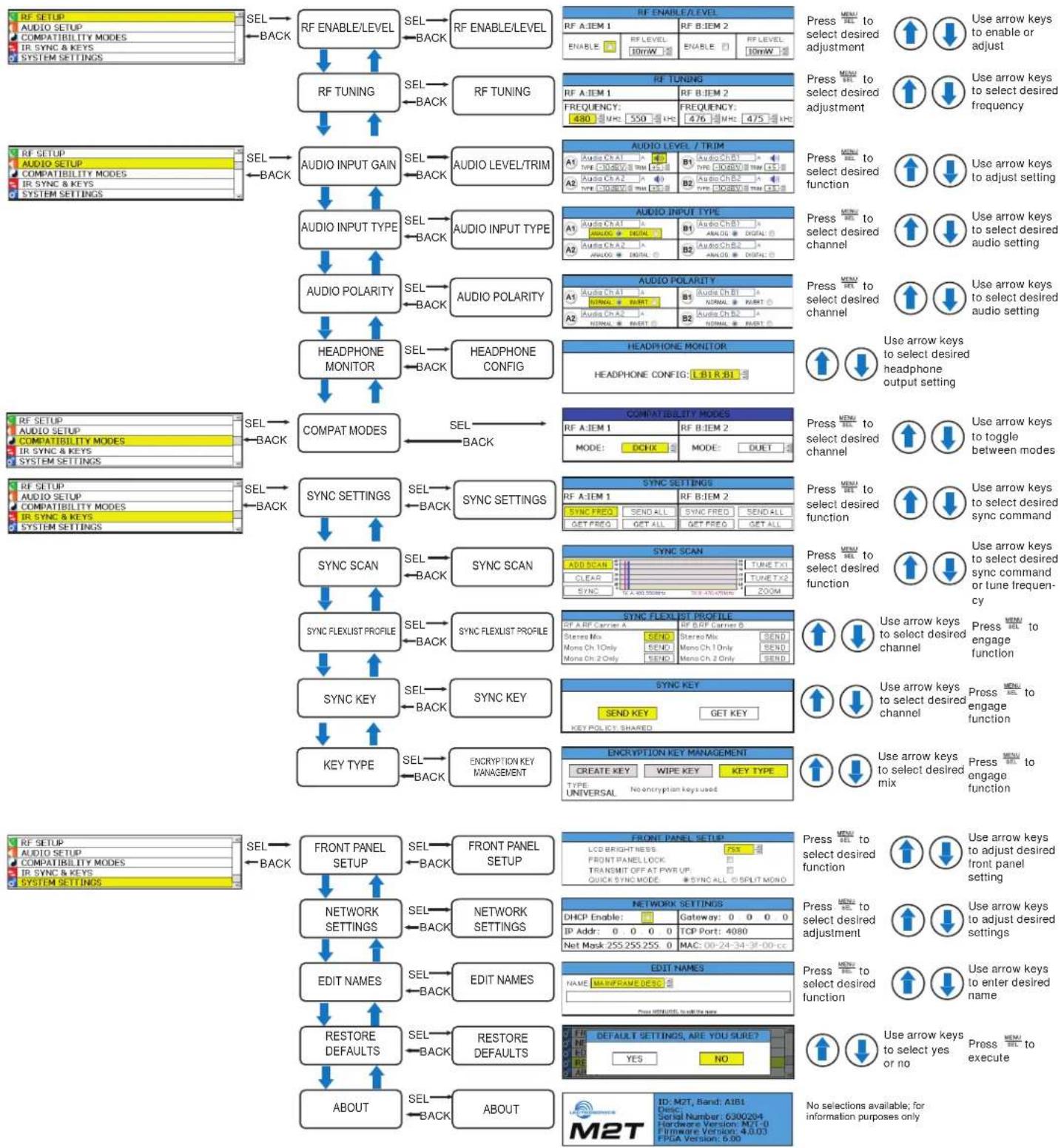
LCD Menu Map
Main Menu Tree
flowchart
graph TD
    A["RF SETUP"] --> B["RF ENABLE/LEVEL"]
    B --> C["RF ENABLE/LEVEL"]
    C --> D["RF ENABLE/LEVEL"]
    D --> E["RF TUNING"]
    E --> F["RF TUNING"]
    F --> G["AUDIO INPUT GAIN"]
    G --> H["AUDIO INPUT TYPE"]
    H --> I["AUDIO POLARITY"]
    I --> J["HEADPHONE MONITOR"]
    J --> K["COMPAT MODES"]
    K --> L["COMPATABILITY MODES"]
    L --> M["SYNC SETTINGS"]
    M --> N["SYNC SCAN"]
    N --> O["SYNC FLEXUST PROFILE"]
    O --> P["SYNC KEY"]
    P --> Q["KEY TYPE"]
    Q --> R["ENCRIPTION KEY MANAGEMENT"]
    R --> S["ENCRYPTION KEY MANAGEMENT"]
    S --> T["FRONT PANEL SETUP"]
    T --> U["FRONT PANEL SETUP"]
    U --> V["NETWORK SETTINGS"]
    V --> W["EDIT NAMES"]
    W --> X["RESTORE DEFAULTS"]
    X --> Y["ABOUT"]

    subgraph Legend
        Z["RF SETUP"] --> AA["AUDIO SETUP"]
        AA --> AB["COMPATIBILITY MODES"]
        AB --> AC["IR SYNC & KEYS"]
        AB --> AD["SYSTEM SETTINGS"]
        AE["RF SETUP"] --> AF["AUDIO SETUP"]
        AF --> AG["COMPATIBILITY MODES"]
        AG --> AH["IR SYNC & KEYS"]
        AG --> AI["SYSTEM SETTINGS"]
        AJ["RF SETUP"] --> AK["AUDIO SETUP"]
        AK --> AL["COMPATIBILITY MODES"]
        AL --> AM["IR SYNC & KEYS"]
        AL --> AN["SYSTEM SETTINGS"]
        AO["RF SETUP"] --> AP["AUDIO SETUP"]
        AP --> AQ["COMPATIBILITY MODES"]
        AQ --> AR["IR SYNC & KEYS"]
        AO --> AS["RF SETUP"] --> AT["DATA Setup"]
    end

    style Legend fill:#f9f,stroke:#333,stroke-width:2px
Menu Item Descriptions
RF Enable/Level
Allows RF transmission to be turned on and off and set RF levels at 10, 25 or 50 mW (E06 options are 20, 50 or 100 mW EIRP).
| RF ENABLE/LEVEL | |||
| RF A: IEM 1 | RF B: IEM 2 | ||
| ENABLE: | RF LEVEL:10mW | ENABLE: | RF LEVEL:10mW |
RF Tuning
Allows manual selection of the operating frequency.
| RF TUNING | |
| RF A:IEM 1 | RF B:IEM 2 |
| FREQUENCY:480 MHz. 550 kHz | FREQUENCY:476 MHz. 475 kHz |
Audio Input Gain
Allows adjustment of input sensitivity and trim for each audio input channel for analog sources.
| AUDIO LEVEL / TRIM | ||
| A1Audio Ch A1ATYPE: -10dBV TRIM: +5 | B1Audio Ch B1ATYPE: -10dBV TRIM: +5 | |
| A2Audio Ch A2ATYPE: -10dBV TRIM: +5 | B2Audio Ch B2ATYPE: -10dBV TRIM: +5 | |
Audio Input Type
Allows selection of input type by channel, either analog or digital (Dante).
| AUDIO INPUT TYPE | |
| A1Audio Ch A1ANA LOG DIGITAL | B1Audio Ch B1ANALOG DIGITAL |
| A2Audio Ch A2ANALOG DIGITAL | B2Audio Ch B2ANALOG DIGITAL |
Audio Polarity
Allows selection of audio polarity by channel.
| AUDIO POLARITY | |
| A1Audio Ch A1 ANORMAL INVERT. | B1Audio Ch B1 ANORMAL INVERT. |
| A2Audio Ch A2 ANORMAL INVERT. | B2Audio Ch B2 ANORMAL INVERT. |
Headphone Monitor
Allows selection of audio channels fed to headphones.
| HEADPHONE MONITOR |
| HEADPHONE CONFIG: L:B1 R:B1 |
Compatibility Modes
Allows selection of encrypted (DCHX) or non-encrypted (Duet) audio encoding.
| COMPATIBILITY MODES | |
| RF A: IEM 1 | RF B: IEM 2 |
| MODE: DCHX | MODE: DUET |
Sync Settings
Allows sending or retrieving setup data via IR port.
| SYNC SETTINGS | |||
| RF A:IEM 1 | RF B:IEM 2 | ||
| SYNC FREQ | SEND ALL | SYNC FREQ | SEND ALL |
| GET FREQ | GET ALL | GET FREQ | GET ALL |
| SYNC RFX 1 FREQ | |
| Hold RX up to IR PORT and press GO | |
| CANCEL | GO |
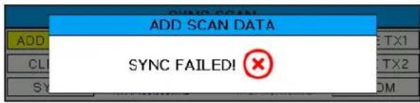
Sync Scan
Receive frequency scan via IR port or tune transmitters manually.
| SYNC SCAN | |
| ADD SCAN | TUNE TX1 |
| CLEAR | TUNE TX2 |
| SYNC | ZOOM |
| TX A: 480.550MHz | TX B: 476.475MHz |
| ADD SCAN DATA | |
| Hold RX up to IR PORT and press ADD | |
| CANCEL | ADD |
| ADD SCAN DATA | |
| GETTING SCAN DATA! |
Screen will alert user if scan is unsuccessful.
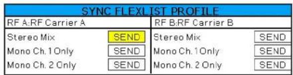
Sync FlexList Profile
FlexList allows the user to set up a list of profiles, by name, in the receiver. This allows quick and easily access to listen to any of the mixes on site.
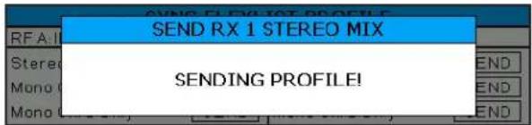
After putting the receiver into Sync Flex mode, choose the function and then use the transmitter to send the profile over IR:
Stereo Mix: The current receiver settings are sent as is, except the mix mode is set to stereo.
Mono Ch. 1 Only: The current receiver settings are sent as is, except the mix mode is set to Mono Ch. 1.
Mono Ch. 2 Only: The current receiver settings are sent as is, except the mix mode is set to Mono Ch. 2.
NOTE: See Mix Mode for more information.
Also see Page 20 for details on creating, editing, and storing Flexlists within Wireless Designer

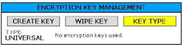
Sync Key
Allows sending of encryption key to other devices, or getting key from another device using IR sync.

Key Type
Allows selection of encryption key policy: universal, shared, standard, or volatile. Allows creation of new key or deletion of the current key.
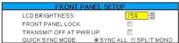
Front Panel Setup
Front panel settings may be customized as follows:
- LCD brightness
- Front panel lock
- Startup RF state
- Quick Sync Mode
Sync All: A long (1 second) press of either the A1, A2, B1 or B2 buttons sends all RX1 settings.
Split Mono: A long press of the A1 or B1 buttons sends all RX1 settings with the mix mode forced to Mono Ch. 1. A long press of the A2 or B2 buttons sends all RX1 settings with the mix mode forced to Mono Ch. 2.
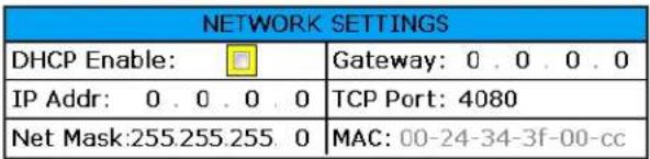
Network Settings
Allows the user to set IP address or other network settings when needed.
NOTE: New network settings require the unit to reboot to take effect. Making a change and pressing the BACK key will prompt the user to Reboot Now, Save and Exit, or Discard and Exit.
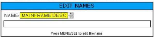
Edit Names
Edit names to match talent for easy location in the Flex-List or easily identify multiple M2T, M2T/E01, M2T/E02, M2T/E06 transmitters in a rack.
- Use UP and DOWN Arrows to select letters and MENU/SEL to set and move cursor.
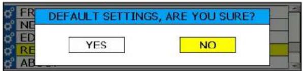
Restore Defaults
Returns all settings to the factory defaults.
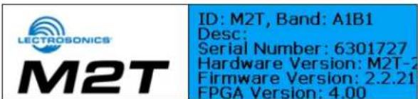
About
Displays general information about the M2T, M2T/E01, M2T/E02, M2T/E06, including serial number, and the hardware, FPGA and microcontroller firmware versions.
Accessories
DCR15/4AU
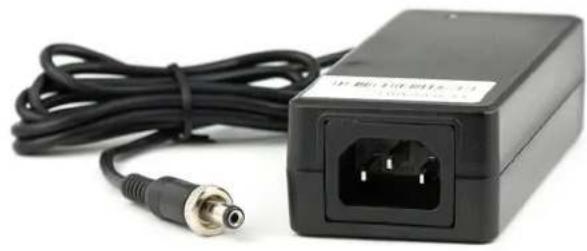
natural_image
Black electronic device with attached power connector and cable, no visible text or symbolsFront Mount Antenna Kit FMAKM2T
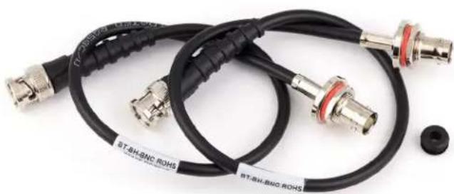
natural_image
Coiled black and metallic coaxial cable with connectors, no visible text or symbols27080 Dante Port Cover
(included with Non-Dante Model)
(Included in Dante Model)
Dante 4X4-TM Dante Card Kit
RMPM2T-1
Rack kit for mounting one M2T, M2T/E01, M2T/E02, M2T/E06 into a single rack space
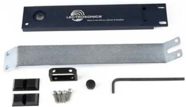
natural_image
Product photo of an LECTROSONICS device with attached metal strip, screws, and mechanical components (no visible text or symbols)SNA600a Antenna
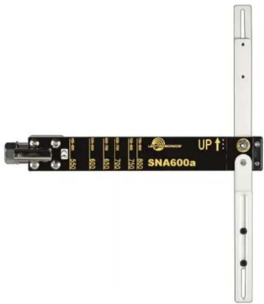
SNA600a Accessories:
ARG 15
A 15 foot antenna cable of standard RG-58 coax cable with BNC connectors at each end.
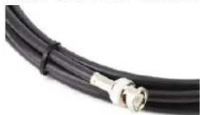
natural_image
Close-up of a black cable with metallic connectors (no text or symbols visible)ARG 25 Antenna cable of Belden 9913F low-loss coax cable with BNC connectors at each end. 25 foot length.

natural_image
Close-up of a black cable with metallic connectors, wrapped in a strap (no text or symbols visible)Hardware Installation

Unpacking the Unit
Compare the packing list enclosed with the M2T, M2T/E01, M2T/E02, M2T/E06 with the original order. Inspect all items for damage. Immediately call 1-800-821-1121 to report any items that are missing or damaged. The sooner we get notified, the sooner we can get any needed replacement items shipped to your location.
Items Included in the Box:
- Instruction manual
• (DCR15/4AU) Power supply cable
• (21926) USB cable
• (35800) Hex L key wrench
• (25990) Bracket rear tie
• (25991) Bracket front tie
• (27076) Rack flange bracket
• (27082) Rack handle
• (28885) (4) SCR10 cap screw
• (35664) (4) Rubber foot large
• (35959) Hole plug
• (A500RA19) (2) Antennas
(A500RA22) (2) Antennas
A1B1 Units
• (A500RA22) (2) Antennas
(A500RA25) (2) Antennas
B1C1 Units
Installing two M2T, M2T/E01, M2T/E02, M2T/E06 Transmitters into a Single Rack Space
The M2T, M2T/E01, M2T/E02, M2T/E06 transmitter occupies a half rack space, and comes with hardware to mount two transmitters into a single rack space.
- Remove the Trim Cap (Part #P1330) from both sides of the front panel on both transmitters.
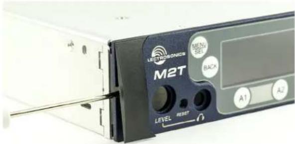
- Remove the breakaway tabs on both sides of the chassis side panels. Use a flat blade screwdriver to pry the tabs outward and snap them off of the chassis.

natural_image
Close-up of a device rear panel showing a M2T device with labeled buttons and ports (no readable text beyond branding)- Insert the flange bracket (Part #27076) into the open slot in the side of the chassis cover panel.

natural_image
Close-up of a blue electronic device component with labeled ports (M2T, Level, RESET) and buttons (no readable text beyond labels)- Insert two (2) cap screws (Part #28885) through the rack handle (Part #27082) holes and install the rack handle onto the flange bracket through the holes in the unit's front panel. Firmly tighten the cap screws using the hex key (Allen wrench) as shown.
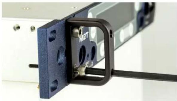
natural_image
Close-up of a mechanical assembly with blue mounting bracket and black connector (no visible text or symbols)- If antennas will NOT be mounted on the front panel of the transmitters, install the hole cap (Part #35959) by aligning the flat on the cap with the flat on the opening.

- Install one side of the front tie bracket (Part #25991) into the side panel opening in one of the transmitters. Insert the screws, but do not tighten them completely at this point.
NOTE: The retaining nuts on the panel and tie brackets are "tensioning lock nut" types designed to prevent the screws from coming loose due to vibration. You will usually feel resistance as you tighten the screws - this is normal.
Slide the other transmitter over the tie bracket and insert the screws, but do not tighten them completely until the rear tie bracket is installed.
- Remove the four cap screws from the adjacent rear panels, and then use them to attach the rear tie bracket. Do not tighten the screws completely.
- After front and rear tie brackets are installed, place the transmitters on a flat surface so the that the front panels are even with each other. Hold the transmitters in place and tighten all cap screws on the front and rear brackets.
NOTE: If the supplied rubber feet are installed on under side of M2T, M2T/E01, M2T/E02, M2T/E06, it will not fit in a rack unless there is an empty space below it.

Rear tie bracket (Part #25990)
Front tie bracket (Part #25991)

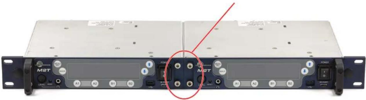
natural_image
Front view of a black M2T rack unit with labeled ports and buttons, showing internal components and a red circle highlighting the central portion (no readable text beyond labels)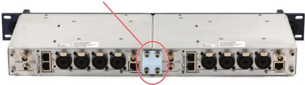
natural_image
Front view of a network equipment chassis with multiple ports and connectors, no visible text or symbols on the device itself.Installing One M2T into a Single Rack
The M2T transmitter occupies a half rack space. This kit provides the hardware needed to mount one M2T or DSQD into a single rack space.
NOTE: Steps 1-6 will require original mounting hardware that came with the units. Part numbers are included in case individual items need to be reordered.
- Remove the Trim Cap (Part #P1330) from both sides of the front panel of the M2T unit to be rack mounted.

- Remove the breakaway tabs on both sides of the Chassis Cover Panel. This requires the use of a flat-blade screwdriver inserted into the slots and levering the tabs away on each side of the unit.

- Insert the Flange Bracket (Part #27076) into the open slot in the left-front side of the Chassis Cover Panel.

natural_image
Close-up of a blue MEMS device with labeled ports and connectors (no readable text beyond branding)- Insert two (2) Cap Screws (Part #28885) through the Rack Handle (Part #27082) holes and install the Rack Handle onto the Flange Bracket through the holes in the unit's front panel. Firmly tighten the Cap Screws using the long leg of the Hex Wrench as shown.
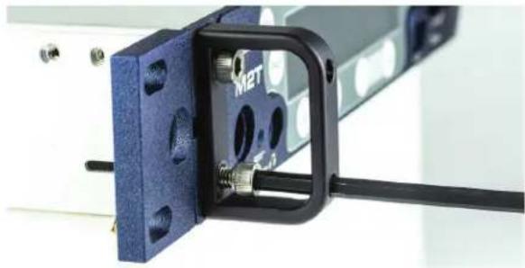
natural_image
Close-up of a blue mechanical component with a black bracket and metallic pins, mounted on a white surface (no visible text or symbols)- Unless also installing a Front Mounted Antenna, insert the Hole Plug (Part #35959) into the open antenna hole in the Flange Bracket by aligning the flat sides of the plug with those of the bracket hole and pushing into place until flush.

natural_image
Close-up of a blue mechanical component with mounting holes and a black lever mechanism (no visible text or symbols)- Install the Front Tie Bracket (Part #25991) into the open slot in the right side of the M2T Chassis Cover Panel with the protruding nuts facing rearward, affix with two (2) Cap Screws (Part #28885) provided and firmly tighten with the Hex Wrench. See next page.
NOTE: Steps 7-11 require parts from the (RMPM2T-1) M2T Single Rack Mount Kit.
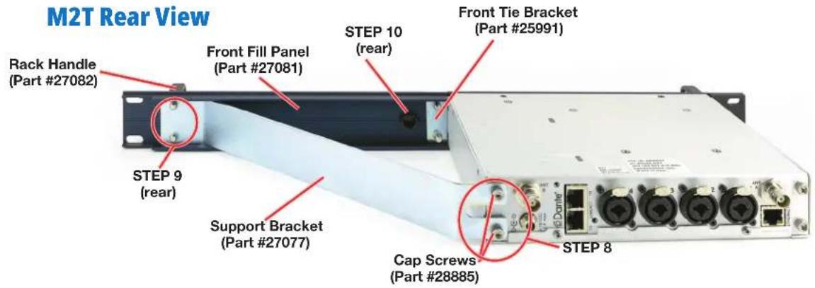
M2T Front View

Items Included in RMPM2T-1 Kit:
• Technical Data Sheet
• (27077) Support Bracket
• (27081) Front Fill Panel
• (27082) Rack handle
• (28885) (4) SCR10 cap screw
• (35800) Hex L key wrench
• (35959) Hole plug
• (28950) (2) Long mounting screws*
• (28951) (2) Short spacer tubes*
NOTE: Starred (*) items are needed only when installing a DSQD, They are not needed for M2T installation and may be set aside.
- Use two (2) Cap Screws (Part #28885) to attach the left side of the Front Fill Panel (Part #27081) to the two remaining nuts on the Front Tie Bracket (Part #25991) and firmly tighten with the Hex Wrench.
- Use the Hex Wrench to remove the two (2) in-board Cap Screws from the rear of the M2T. Install the Support Bracket (Part #27077) to the rear panel of the M2T, reusing the two (2) Cap Screws previously removed and firmly tighten with the Hex Wrench. (See rear view image above.)
- Insert two (2) Cap Screws (Part #28885) through Rack Handle (Part #27082) holes and install the Rack Handle onto the right side Front Fill Panel (Part #27081) through the holes in the panel,

natural_image
Product photo of a LECTROSONICS mechanical component with screws, bolts, and a wrench (no visible text or symbols)and into the nuts on the Support Bracket (Part #27076). Firmly tighten the Cap Screws using the long leg of the Hex Wrench. (See rear and front view images on front page.)
- Unless also installing a Front Mounted Antenna, insert the Hole Plug (Part #35959) into the open antenna hole in the Front Fill Panel (Part #27081) by aligning the flat sides of the plug with those of the bracket hole and pushing into place until flush.
The M2T with Front Fill Panel is now ready for installation into a rack.
NOTE: If supplied rubber foot/feet are installed on under side of the M2T, it will not fit in a single rack space.
DSQD Rear View

Installing One DSQD into a Single Rack
The process to install the DSQD is the same as for the M2T transmitter through Step 7. The DSQD looks similar to the M2T in the frontal view. Follow the steps for the M2T, then resume at Step 8:
-
Use the Hex Wrench to remove the two (2) in-board Cap Screws from the rear of the DSQD. Put them aside and save for later use or spares; you will not need them for this installation. Install the Support Bracket (Part #27077) to the rear panel of the DSQD, using the two (2) long mounting screws, threaded with Spacer Tubes, and firmly tighten with the Hex Wrench. See rear view image and call-out photo above. The kit is designed to handle the M2T and the DSQD with a shorter chassis, so the spacers are included.
-
Insert two (2) Cap Screws (Part #28885) through the Rack Handle (Part #27082) holes and install the Rack Handle onto the right side Front Fill Panel (Part #27081) through the holes in the panel, and into the nuts on the Support Bracket (Part #27076). Firmly tighten the Cap Screws using the long leg of the Hex Wrench.
-
Unless also installing a Front Mounted Antenna, insert the Hole Plug (Part #35959) into the open antenna hole in the Front Fill Panel (Part #27081) by aligning the flat sides of the plug with those of the bracket hole and pushing into place until flush.
The DSQD with Front Fill Panel is now ready for installation into a rack.
NOTE: As with the M2T, if the supplied rubber foot/feet are installed on under side of the DSQD, it will not fit in a single rack space.
Mounting M2T To DSQD
When mounting two M2Ts or two DSQDs together, the units lie flush together as shown. This is not the case with an M2T and a DSQD, as the DSQD housing is shorter and the spacer tubes are needed.

natural_image
Front view of a network equipment unit with multiple ports and connectors (no visible text or symbols)Two M2T units

natural_image
Front view of a network equipment unit with multiple ports and connectors (no visible text or symbols)Two DSQD units
When attaching an M2T to a DSQD unit, the preferred configuration (when viewing from the back side) is to have the DSQD to the left and the M2T to the right. If the units are mounted the opposite way, the mounting plate will partially block the Dante ^® ports on the DSQD, making it difficult to remove the cables. Having the DSQD on the left as shown below eliminates this inconvenience.
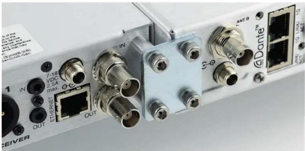
Recommended DSQD-M2T mounting
Wireless Designer Software
Download the Wireless Designer software installer from the web sites under the SUPPORT tab at:
http://www.lectrosonics.com
Once the software is installed, updates are available by simply clicking on "Check for updates" in the Help Menu.
Crreate, Edit, Store Flexlists in Wireless Designer
Starting with Wireless Designer v2.1.0 for Mac or PC, users now have the ability to create, load, save and send Flexlists to receivers via an M2T-type device. Flexlists now include an optional compatibility mode setting, allowing Flexlist entires for receivers operating in different compatibility modes.
NOTE: These functional enhancements are available with M2T firmware update M2T v4.0.03 (SUPER)/v6.00 (FPGA, H/W v0 & v1)/v7.00 (FPGA, H/W v2 & v3) and later.
Firmware Update Instructions
Firmware updates are made with a file downloaded from the web site and the M2T connected via USB.
The USB port on the transmitter requires a micro-B male plug on the connecting cable. The other end of the cable would normally be a USB A-type or C-type male connector to fit the most common type of USB jack used on computers.
Refer to Help in Wireless Designer software for the procedure.
Specifications
RF Power Output: • Two carriers; two audio channels each
- M2T, M2T/E01, M2T/E01: Power adjustable on each carrier to 10, 25 or 50 mW
M2T/E06: Power adjustable on each carrier to 20, 50 or 100 mW EIRP
Antenna Output: 2 x BNC sockets
Operating Frequencies:
M2T (A1B1) 470.100 - 607.975 MHz M2T/E01 (A1B1) 470.100 - 614.375 MHz M2T/E01-B1C1 537.600 - 691.175 MHz M2T/E02 470.150 - 614.375 MHz M2T/E06 520.000 - 614.375 MHz
NOTE: It's the user's responsibility to select the approved frequencies for the region where the transmitter is operating
Operating Temperature
Range: Celsius: -20^ - 40^ Farenheit: -5^ - 104^
Frequency Selection
Steps: 25 kHz
Frequency Stability: ± 0.002%
Modulation: 8 PSK
Emission
Designator: 200KG7E
Spurious Radiation: Compliant with ETSI EN 300 422-1
Encryption: AES 256 bit CTR mode, when loaded with v3.X firmware
Equivalent input
Noise: -128 dBV
Latency: (overall system)
Digital Source: 1.0 ms plus Dante network (on Dante unit)
Analog Source: <1.8 ms
Audio Frequency
Response: 10 Hz – 11.5 kHz, -1 dB
Audio Input: -10 dBV or +4 dBu settings w/ ±5 dB trim
Audio Input Jack: 4 x combo XLR/TRS connectors
Input impedance: Line: 2k Ohm
Dante Connection: 2 x RJ45, 4 audio RX channels, internally routable
Ethernet Connection: RJ45
USB Connection: Micro USB on front panel for firmware updates
IRDA: IR transceiver for sync of receivers
Headphone jack 3.5 mm stereo jack
Power
Requirements: 9-18 VDC
Power Consumption: 11 Watts
Weight: 2.2 lbs (997.903 grams)
Dimensions: Height: 1.750 in. / 44.45 mm
Width: 8.375 in. / 212.7 mm
Depth: 7.750 in. / 196.8 mm
Origin: Designed and manufactured in the USA
Specifications subject to change without notice.
Service and Repair
If your system malfunctions, you should attempt to correct or isolate the trouble before concluding that the equipment needs repair. Make sure you have followed the setup procedure and operating instructions. Check the interconnecting cables and then go through the Troubleshooting section in this manual.
We strongly recommend that you do not try to repair the equipment yourself and do not have the local repair shop attempt anything other than the simplest repair. If the repair is more complicated than a broken wire or loose connection, send the unit to the factory for repair and service. Don't attempt to adjust any controls inside the units. Once set at the factory, the various controls and trimmers do not drift with age or vibration and never require readjustment. There are no adjustments inside that will make a malfunctioning unit start working.
LECTROSONICS' Service Department is equipped and staffed to quickly repair your equipment. In warranty repairs are made at no charge in accordance with the terms of the warranty. Out-of-warranty repairs are charged at a modest flat rate plus parts and shipping. Since it takes almost as much time and effort to determine what is wrong as it does to make the repair, there is a charge for an exact quotation. We will be happy to quote approximate charges by phone for out-of-warranty repairs.
Returning Units for Repair
For timely service, please follow the steps below:
A. DO NOT return equipment to the factory for repair without first contacting us by email or by phone. We need to know the nature of the problem, the model number and the serial number of the equipment. We also need a phone number where you can be reached 8 A.M. to 4 P.M. (U.S. Mountain Standard Time).
B. After receiving your request, we will issue you a return authorization number (R.A.). This number will help speed your repair through our receiving and repair departments. The return authorization number must be clearly shown on the outside of the shipping container.
C. Pack the equipment carefully and ship to us, shipping costs prepaid. If necessary, we can provide you with the proper packing materials. UPS is usually the best way to ship the units. Heavy units should be "double-boxed" for safe transport.
D. We also strongly recommend that you insure the equipment, since we cannot be responsible for loss of or damage to equipment that you ship. Of course, we insure the equipment when we ship it back to you.
Lectrosonics USA:
Mailing address: Shipping address: Telephone:
Lectrosonics, Inc. Lectrosonics, Inc. (505) 892-4501
PO Box 15900 561 Laser Rd. NE, Suite 102 (800) 821-1121 Toll-free
Rio Rancho, NM 87174 Rio Rancho, NM 87124 (505) 892-6243 Fax
USA USA
Web: E-mail:
www.lectrosonics.com sales@lectrosonics.com
service.repair@lectrosonics.com
Lectrosonics Canada:
| Mailing Address: | Telephone: | E-mail: | ||
| 720 Spadina Avenue, Suite 600 (877) 753-2876 Toronto, Ontario M5S 2T9 | (416) 596-2202 | Sales: joeb@lectrosonics.com | colinb@lectrosonics.com | |
| Toll-free Service: (877-7LECTRO) | ||||
| (416) | 596-6648 | Fax | ||
Self-Help Options for Non-Urgent Concerns
Our Facebook groups and weblists are a wealth of knowledge for user questions and information. Refer to:
Lectrosonics General Facebook Group: https://www.facebook.com/groups/69511015699
D Squared, Venue 2 and Wireless Designer Group: https://www.facebook.com/groups/104052953321109
The Wire Lists: https://lectrosonics.com/the-wire-lists.html
EU Declaration of Conformity
LECTROSONICS, INC.
581 Laser Road
Rio Rancho, NM 87124 USA
Declares under our sole responsibility that the following product:
Model: M2T/E01
Wireless microphone transmitter
is in conformity with the provisions of the following EC directive(s) (including applicable amendments) and are designed and manufactured in accordance with the harmonized standards:
| Document | Description | Date/Version |
| RL 2014/53/EU | Radio Equipment Directive 2014/53/EU (RED) | 2014-04 |
| EN 300 422-1 | Wireless Microphones; Audio PMSE up to 3 GHz; Part 1: Class A Receivers | V2.1.2(2017-01) |
| Electromagnetic Compatibility | ||
| EN 301 489-1 | ElectroMagnetic Compatibility (EMC) standard for radio equipment and services; Common Technical Requirements | V2.2.0(2017-03) |
| EN 301 489-9 | Specific Conditions for wireless microphones, similar Radio Frequency (RF) audio link equipment, cordless audio and in-ear monitoring devices | V2.1.1(2017-03) |
| Safety and Health | ||
| EN 60065-1 | Audio, video and similar electronic apparatus – Safety Requirements | 2014 |
| EN 62311 | Assessment of electronic and electrical equipment related to human exposure restrictions for electromagnetic fields (0 Hz – 300 GHz) | 2008 |
| RL 2011/65/EU | RoHS Directive 2011/65/EU: Restriction of the use of certain hazardous substances (RoHS Recast) | 2011 |
The EU type examination was performed by notified body Bay Area Compliance Laboratories.
Software version of M2T/E01: v1.04
Rio Rancho, NM USA, 07 July 2017
R. Cunningham Robert Cummings
Robert Cunnings
V.P. Engineering
Lectrosonics, Inc.
ISEDC Notices:
Per RSS-210
This device operates on a no-protection no-interference basis. Should the user seek to obtain protection from other radio services operating in the same TV bands, a radio licence is required. Please consult Industry Canada's document CPC-2-1-28, Optional Licensing for Low-Power Radio Apparatus in the TV Bands, for details.
This device complies with Industry Canada's license-exempt RSSs. Operation is subject to the following two conditions:
1) This device may not cause interference
2) This device must accept any interference, including interference that may cause undesired operation of the device.
The equipment is warranted for one year from date of purchase against defects in materials or workmanship provided it was purchased from an authorized dealer. This warranty does not cover equipment which has been abused or damaged by careless handling or shipping. This warranty does not apply to used or demonstrator equipment.
Should any defect develop, Lectrosonics, Inc. will, at our option, repair or replace any defective parts without charge for either parts or labor. If Lectrosonics, Inc. cannot correct the defect in your equipment, it will be replaced at no charge with a similar new item. Lectrosonics, Inc. will pay for the cost of returning your equipment to you.
This warranty applies only to items returned to Lectrosonics, Inc. or an authorized dealer, shipping costs prepaid, within one year from the date of purchase.
This Limited Warranty is governed by the laws of the State of New Mexico. It states the entire liability of Lectrosonics Inc. and the entire remedy of the purchaser for any breach of warranty as outlined above. NEITHER LECTROSONICS, INC. NOR ANYONE INVOLVED IN THE PRODUCTION OR DELIVERY OF THE EQUIPMENT SHALL BE LIABLE FOR ANY INDIRECT, SPECIAL, PUNITIVE, CONSEQUENTIAL, OR INCIDENTAL DAMAGES ARISING OUT OF THE USE OR INABILITY TO USE THIS EQUIPMENT EVEN IF LECTROSONICS, INC. HAS BEEN ADVISED OF THE POSSIBILITY OF SUCH DAMAGES. IN NO EVENT SHALL THE LIABILITY OF LECTROSONICS, INC. EXCEED THE PURCHASE PRICE OF ANY DEFECTIVE EQUIPMENT.
This warranty gives you specific legal rights. You may have additional legal rights which vary from state to state.


- Table of Contents
- Introduction
- What is Dante?
- Summary of Dante Benefits
- Encryption
- System Setup Procedures
- Summary of Steps
- Panels and Features
- Operating Instructions
- IR (infrared) Port
- USB Port
- Reset Button
- Headphone Volume Adjustment
- Antenna Output Jacks
- Dante Ports (optional)
- Ethernet Port
- Power Inlet
- Quick Sync
- Power Screens
- Navigating the Menus
- LCD Menu Map
- Menu Item Descriptions
- RF Enable/Level
- RF Tuning
- Audio Input Gain
- Audio Input Type
- Audio Polarity
- Headphone Monitor
- Compatibility Modes
- Sync Settings
- Sync Scan
- Sync FlexList Profile
- Sync Key
- Key Type
- Front Panel Setup
- Network Settings
- Edit Names
- Restore Defaults
- About
- Accessories
- RMPM2T-1
- ARG 15
- Hardware Installation
- Unpacking the Unit
- Items Included in the Box:
- Installing two M2T, M2T/E01, M2T/E02, M2T/E06 Transmitters into a Single Rack Space
- Installing One M2T into a Single Rack
- Items Included in RMPM2T-1 Kit:
- DSQD Rear View
- Installing One DSQD into a Single Rack
- Mounting M2T To DSQD
- Wireless Designer Software
- Crreate, Edit, Store Flexlists in Wireless Designer
- Firmware Update Instructions
- Specifications
- Service and Repair
- Returning Units for Repair
- Lectrosonics USA:
- Lectrosonics Canada:
- Self-Help Options for Non-Urgent Concerns
- EU Declaration of Conformity
- ISEDC Notices:
- Per RSS-210
Brand : Lectrosonics
Model : M2T-X
Category : Unspecified