
DSR-941 - Audio transceiver Lectrosonics - Free user manual and instructions
Find the device manual for free DSR-941 Lectrosonics in PDF.

| Product Type | Two-Channel Digital Slot Receiver |
| Brand | Lectrosonics |
| Model | DSR-941 |
| Frequency Range | 941.525 - 959.825 MHz |
| Frequency Selection Steps | 25 kHz |
| Frequency Stability | ±0.001% |
| Dimensions (W x H x D) | 3.375 x 1.23 x 4.50 inches (85.7 x 31 x 114 mm) |
| Weight | 408 g (14.4 oz) without audio adapter |
| Power Requirements | External DC 7-18 V, 3.25 W, max 400 mA at 7 VDC |
| Diversity Method | Vector diversity (also supports frequency diversity) |
| Encryption | AES 256-bit, CTR mode with 4 key policies (Universal, Shared, Standard, Volatile) |
| Smart Noise Reduction | Selectable Off/Normal/Full (SmartNR) |
| Audio Outputs | Analog balanced (TA3 male) and AES3 digital; configurable routing |
| Display | Color LCD with selectable backlight timeout |
| Antenna Inputs | Two 50 Ohm SMA female connectors |
| Compatibility Modes | D2, HDM, Duet, DCHX (digital); NA, NU, EU, JA Hybrid (analog) plus all Hybrid modes |
| Firmware Update | Via USB Micro-B top panel connector and Wireless Designer software |
| Warranty | One year from date of purchase against defects |
| Supplied Accessories | Swivelling whip antennas (AMJ944 for block 941), power adapter (not included), USB cable |
| Operating Temperature | Not specified; typical professional use range 0°C to 50°C |
Frequently Asked Questions - DSR-941 Lectrosonics
User questions about DSR-941 Lectrosonics
0 question about this device. Answer the ones you know or ask your own.
Ask a new question about this device
Download the instructions for your Audio transceiver in PDF format for free! Find your manual DSR-941 - Lectrosonics and take your electronic device back in hand. On this page are published all the documents necessary for the use of your device. DSR-941 by Lectrosonics.
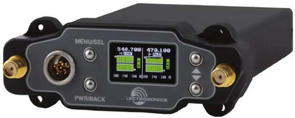
USER MANUAL DSR-941 Lectrosonics
Two Channel Digital Slot Receiver
DSR-A1B1, DSR-B1C1, DSR-941, DSR-961
- Two independent channels, compact design
• Vector diversity for superior performance - Latest generation of SR Series: Compatible with extensive existing Unislot/Superslot ecosystem
- Compatible with D2, HDM, Duet, DCHX Digital modes and all Hybrid modes
• 24 bit/48 kHz digital for flawless audio
- AES 256-bit, CTR mode encryption, with 4 different key policies available
• Analog and AES3 digital audio outputs
• External DC powering options
- USB jack for firmware updates and Wireless Designer connection
CE UK CA

Fill in for your records:
Serial Number:
Purchase Date:

Quick Start Summary
The following checklist includes the minimum required settings to start using the receiver.
• Install either a battery sled, camera slot adapter or other power source via bottom plate adapter.
- Connect power to the receiver.
- Set the COMPAT (compatibility) mode for the transmitters to be used.
- Find clear operating frequencies for one or both receivers using SmartTune or manual scanning.
- Set transmitters on the matching frequencies (see transmitter manual).
- Adjust transmitter input gain to match voice level and mic position (see transmitter manual).
- Adjust level as needed for the camera or mixer input level desired.
Table of Contents
Block Diagram/Schematic......4
Technical Description......5
Front Panel Controls and Functions....6
MENU/SELECT Button....6
PWR/BACK Button....6
Up/Down Arrow Buttons....6
IR (infared) Port 6
Antenna Port (2)......6
Menu Item Descriptions....6
RF Setup....6
Frequency....6
Tuning Groups 7
Scan....7
Scan Zoom 7
Clear Scan....7
Group Edit ....7
Diversity Modes....8
Audio Setup....9
Compat Modes....9
DSR LCD Menu Map....10
IR & Keys Menu....12
Encryption Key Management 12
Settings Menu 13
Antenna Mounting and Orientation ....14
AMJ Jointed and SNA Dipole Antennas ....15
Antenna/Block Reference Table....16
Interference Management....17
Firmware Update Instructions....17
Supplied Parts and Accessories....18
Optional Parts and Accessories....18
Audio Output Cables/Connectors....19
RATPAC Adapter Kit....20
External Power Supplies....20
External Power Cables....21
Camera Slot Adapters & Installation ......22
Rear Panel Adapters & Installation....23
Adapters for Stand-Alone Use ....23
Battery Adapters and Mounting Kits ....24
SRBATTSLED Top/Bottom 24
SR9VBP 9V Adapter ......25
SRSLEEVE Mounting Adapter ....25
SRHARDWARE Adapter Kit ....25
Troubleshooting....26
Specifications and Features......27
Service and Repair....28
Returning Units for Repair 28
Our accessories and parts online store for US customers is now open:
https://store.lectrosonics.com/
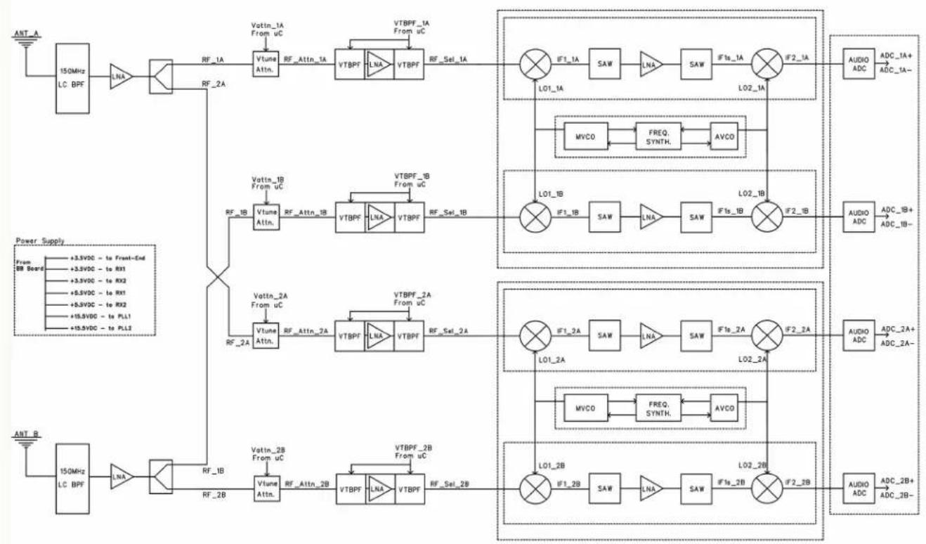
DSR Block Diagram
flowchart
graph TD
    A["ANT_A"] --> B["150MHz LC BPF"]
    B --> C["LNA"]
    C --> D["RF_1A"]
    D --> E["Vtune Attn."]
    E --> F["RF_Attn_1A"]
    F --> G["VTBPF LNA"]
    G --> H["VTBPF"]
    H --> I["RF_Sel_1A"]
    I --> J["IF1_1A"]
    J --> K["SAW"]
    K --> L["LNA"]
    L --> M["SAW"]
    M --> N["IFIs_1A"]
    N --> O["IF2_1A"]
    O --> P["AUDIO ADC"]
    P --> Q["ADC_1A+ ADC_1A-"]
    R["Power Supply"] --> S["From BB Board: +3.5VDC - to Front-End"]
    R --> T["From BB Board: +3.3VDC - to RX1"]
    R --> U["From BB Board: +3.3VDC - to RX2"]
    R --> V["From BB Board: +5.5VDC - to RX1"]
    R --> W["From BB Board: +5.3VDC - to RX2"]
    R --> X["From BB Board: +15.5VDC - to PLL1"]
    R --> Y["From BB Board: +15.5VDC - to PLL2"]

    Z["ANT_B"] --> AA["150MHz LC BPF"]
    AA --> AB["LNA"]
    AB --> AC["RF_1B"]
    AC --> AD["Vtune Attn."]
    AD --> AE["RF_Attn_2B"]
    AE --> AF["VTBPF LNA"]
    AF --> AG["VTBPF"]
    AG --> AH["RF_Sel_2B"]
    AH --> AI["IF1_2A"]
    AI --> AJ["SAW"]
    AJ --> AK["LNA"]
    AK --> AL["SAW"]
    AL --> AM["IFIs_2A"]
    AM --> AN["IF2_2A"]
    AN --> AO["AUDIO ADC"]
    AO --> AP["ADC_2A+ ADC_2A-"]

    B --> AQ["RF_2A"]
    AQ --> AR["Vtune Attn."]
    AR --> AS["RF_Attn_1B"]
    AS --> AT["VTBPF LNA"]
    AT --> AU["VTBPF"]
    AU --> AV["RF_Sel_1B"]
    AV --> AW["IF1_1B"]
    AW --> AX["SAW"]
    AX --> AY["LNA"]
    AY --> AZ["SAW"]
    AZ --> BA["IFIs_1B"]
    BA --> BB["IF2_1B"]
    BB --> BC["AUDIO ADC"]
    BC --> BD["ADC_1B+ ADC_1B-"]

    D --> BE["Vattn_1B From uC"]
    BE --> BF["Vtune Attn."]
    BF --> BG["VTBPF LNA"]
    BG --> BH["VTBPF"]
    BH --> BI["RF_Sel_1B"]
    BI --> BJ["IF1_1B"]
    BJ --> BK["SAW"]
    BK --> BL["LNA"]
    BL --> BM["SAW"]
    BM --> BN["IFIs_1B"]
    BN --> BO["IF2_1B"]

    AC --> BP["Vattn_2A From uC"]
    BP --> BQ["Vtune Attn."]
    BQ --> BR["VTBPF LNA"]
    BR --> BS["VTBPF"]
    BS --> BT["RF_Sel_2A"]
    BT --> BU["IF1_2A"]
    BU --> BV["SAW"]
    BV --> BW["LNA"]
    BW --> BX["SAW"]
    BX --> BY["IFIs_2A"]
    BY --> BZ["IF2_2A"]

    AD --> CA["Vattn_2B From uC"]
    CA --> CB["Vtune Attn."]
    CB --> CC["VTBPF LNA"]
    CC --> CD["VTBPF"]
    CD --> CE["RF_Sel_2B"]
    CE --> CF["IF1_2B"]
    CF --> CG["SAW"]
    CG --> CH["LNA"]
    CH --> CI["SAW"]
    CI --> CJ["IFIs_2B"]
    CJ --> CK["IF2_2B"]

    D --> CL["Vattn_2A From uC"]
    CL --> CM["Vtune Attn."]
    CM --> CN["VTBPF LNA"]
    CN --> CO["VTBPF"]

    AE --> CP["Vattn_2B From uC"]
    CP --> CQ["Vtune Attn."]
    CQ --> CR["VTBPF LNA"]

    AF --> CS["Vattn_2A From uC"]
    CS --> CT["Vtune Attn."]
    CT --> CU["VTBPF LNA"]

    AG --> CV["Vattn_2A From uC"]
    CV --> CW["Vtune Attn."]

    AH --> CX["Vattn_2A From uC"]
    CX --> CY["Vtune Attn."]

    AI --> CZ["Vattn_2B From uC"]
    CZ --> DA["Vtune Attn."]

    AD --> DB["Vattn_2A From uC"]
    DB --> DC["Vtune Attn."]

    AE --> DD["Vattn_2A From uC"]
    DD --> DE["Vtune Attn."]

    AF --> DF["Vattn_2A From uC"]
    DF --> DG["Vtune Attn."]

    AG --> DH["Vattn_2A From uC"]
    DH --> DI["Vtune Attn."]

    AC --> DJ["Vattn_2A From uC"]
    DJ --> DK["Vtune Attn."]

    AD --> DL["Vattn_2A From uC"]
    DL --> DM["Vtune Attn."]

    AE --> DE
    DE --> DN["Vtune Attn."]

    AF --> DO
    DO --> DP["Vtune Attn."]

    AG --> EQ["Vattn_2A From uC"]
    EQ --> RQ["Vtune Attn."]

    AH --> SC["Vattn_2A From uC"]
    SC --> SD["Vtune Attn."]

    AI --> TE["Vattn_2A From uC"]
    TE --> DU["Vtune Attn."]

    AD --> DV["Vattn_2A From uC"]
    DV --> DW["Vtune Attn."]

    AE --> DX["Vattn_2A From uC"]
    DX --> DY["Vtune Attn."]

    AF --> DX
Technical Description
The DSR digital 2-channel receiver is a much-requested, versatile slot receiver, equally appropriate for bag use, as well as camera hop applications. It has been specially designed to be Unislot mount-compatible.
Compatibility Modes
The DSR receiver was designed to operate with Lec-trosonics digital transmitters from the D2, DCH and M2 series. The receiver is also backward compatible with Digital Hybrid Wireless® transmitters including those with NA Hybrid, NU Hybrid, JA HYBRID and EU Hybrid modes.
Encryption
The DSR receiver features AES 256-bit, CTR mode encryption, with 4 different key policies available. For use with D2, DCHX and HDM Compat modes.
Vector Diversity
An ideal diversity system constructively combines all the energy available at both antennas. For 2-channel operation, receivers can be paired for Vector Diversity operation. The Vector subsystem smoothly and continuously combines RF signals from both channels, with differing phase angles in order to obtain maximum energy. The four receivers in the DSR can be use separately or combined in pairs.
RF Frequency Tracking Front-End
In addition to the extremely high IP3 capability of the receiver, to significantly reduce unwanted interference and intermodulation problems, the DSR has a frequency selective front-end section that tracks and tunes to the desired signal frequency and rejects unwanted interfering signals. The low noise, high current RF amplifier was designed with feedback regulation for stability and precise gain in order to handle stronger RF signals without overload.
Smart Noise Reduction (SmartNR™)
The wide dynamic range and frequency response of modern wireless systems makes it possible to hear the -120 dBV noise floor in the transmitter's mic preamp, or the (usually) greater noise from the lav microphone itself. In order to reduce this noise and thus increase the effective dynamic range of the system, the DSR is equipped with a selectable Smart Noise Reduction algorithm, which removes hiss without sacrificing high frequency response.
The Smart Noise Reduction algorithm works by attenuating only those portions of the audio signal that fit a statistical profile for randomness or “electronic hiss.” Desired high frequency signals having some coherence such as speech sibilance and tones are not affected.
The Smart Noise Reduction algorithm has three modes - OFF/NORMAL/FULL - selectable from a user setup screen. When switched OFF (the default setting for
digital compat modes) no noise reduction is performed and complete transparency is preserved. All signals presented to the transmitter's front end, including any faint microphone hiss, will be faithfully reproduced at the receiver. When switched to NORMAL, (the factory default setting for Hybrid modes) enough noise reduction is applied to remove most of the hiss from the mic preamp and some of the hiss from lavaliere microphones. When switched to FULL, enough noise reduction is applied to remove most of the hiss from nearly any signal source of reasonable quality, assuming levels are set properly at the transmitter. This additional noise reduction comes at the cost of some transparency for low-level room noise, yet the algorithm remains undetectable under most circumstances.
Audio Output Level
A setup screen is provided for adjusting the audio output level in 1 dB increments from -50 to +7 dBu using the front panel MENU/SEL, UP, and DOWN buttons.
Test Tone
To assist in matching the audio levels of equipment connected to the DSR, a 1 kHz audio test tone, adjustable from -50 to +7 dBu in 1 dB increments, is available at the outputs. If using AES3 outputs, the level is fixed and cannot be adjusted.
Power Supply
The DSR is operated from an external DC power source. The receiver has a built-in Poly-Fuse for protection. This fuse automatically resets if the power supply is disconnected for about 15 sec. The power section also has protection circuits that prevent damage to the receiver if a positive ground power source is applied.
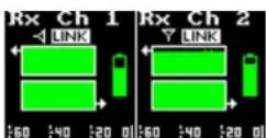
Color LCD Display
The display has four primary “home” windows. Pressing the Front Panel PWR/BACK button steps through each of these windows. After power is turned off and back on again, the unit defaults to the Main window and to the most recent frequencies, audio levels, transmitter battery conditions, and other user settings. The display illumination can be set to time out in 5 seconds, 30 seconds, or never.


Power Off
When the Front Panel Power/Back button is pressed for several seconds, the audio output is instantly muted (squelched) and the message "POWERING OFF..." is displayed briefly before the receiver switches off.
DSR Front Panel Controls

MENU/SEL Button
The MENU button accesses the available menus and selects the desired setting.
PWR/BACK Button
The PWR/BACK button is used to turn the receiver on and off. When browsing menus and making changes to settings, press PWR/BACK to return to previous menu.
Up/Down Arrow Buttons
The UP/DOWN buttons are used to scroll or input the various options within each menu selection.
Antenna Port (2)
IR (infrared) Port
Settings can be transferred between transmitter and receiver or receiver and receiver.
Menu Item Descriptions
RF Setup
Finding Clear Frequencies with SmartTune:
SmartTune is the easiest and fastest way to scan the local RF spectrum and find clear operating frequencies. The receiver will scan through the selected tuning bandwidth and automatically find “empty” areas within the tuning range that have little or no RF energy. The receiver will then be set to a frequency within an empty area and prompt you to continue or use the IR function to sync to a transmitter.
Note: Pressing BACK during an active scan will restore the operating frequency to what it was set at pre-scan.
Transmit frequency range is compatibility mode dependent (see Compat Mode for further details). Tune Receiver 1 is the first screen you will see when you enter SmartTune. After selecting either Tune Rx1 or 2, using the UP/DOWN buttons, press MENU/SEL to open the TX Range? page, then use the UP/DOWN buttons to select the frequency range of the transmitter.

After choosing the band, the unit will scan the available spectrum and choose the frequency with the lowest interference and will display it as shown. If there is already a frequency programmed, you will have the choice to choose the Old (Existing Frequency) or New Frequency. Press the UP/DOWN buttons to toggle between the choices, and press MENU/SEL to choose.
| Tune Rx1? | |
| Old | New |
| A1B1 | A1B1 |
| 561.800 | 538.300 |
The chosen frequency will appear, with a "GO!" icon in the lower right corner of the screen.
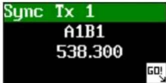
Face the transmitter's IR port within a few inches of the receiver's IR port and press the DOWN button to begin the sync. In digital compat modes, if the sync is successful, the message "Sync OK" will appear on screen. If unsuccessful, the message will show "IR Sync Failed". For Hybrid compat modes, "GO!" at the lower right will blink, but the sync status will only show on the transmitter's display.
After the sync of Channel 1, choose MENU/SEL and the screen will ask Do RX 2 Next? Use the UP/DOWN buttons to toggle between Yes and No; use MENU/SEL to confirm. The screen will ask if you have Transmitter 1 on. This ensures that the transmitters are tuned in a way that they don't interfere with each other.
It will then ask for TX2 Range? After you choose your range, choose MENU/SEL and the DSR will search for a clear frequency. It will ask to sync. Press the DOWN button to sync the transmitter to the receiver. When complete, press PWR/BACK to return to the MAIN SCREEN.
Frequency:
Allows manual selection or group tuning of the operating frequency for each channel. The frequency setup screen has different fields depending on mode selected. In digital modes, with no tuning group selected, the frequency setup page has four fields: receiver name, MHz, kHz, and group selector. In Hybrid modes, with no tuning group selected, the page has six fields: receiver name, block selector, legacy hex code, MHz, kHz, and group selector. The block selector can be used for block disambiguation for any frequencies that overlap between blocks 470 and 19, or between blocks 23-24 and 606.
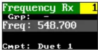
Digital Mode
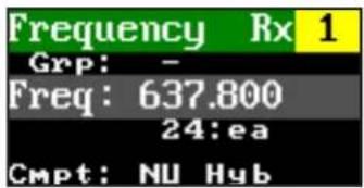
Hybrid Mode
To manually tune: start by selecting Channel 1 or 2 in the upper right corner. Then, press MENU/SEL to select the desired field to edit, using the UP or DOWN buttons. MHz value can be changed in increments of 1 MHz by pressing the UP or DOWN buttons. To keep the selected value, press the MENU/SEL button. The kHz value can be changed in increments of 25 kHz by pressing the UP or DOWN buttons. Pressing MENU/SEL and UP or DOWN at the same time tunes in larger steps. In the MHZ field, in 10 MHz steps; in the kHz field, in 100 kHz steps.
Tuning Groups:
Tuning groups are an important feature within the RF Setup menu that allow the user to create, store, share, recall, and use lists of frequencies with associated names and compat modes, quickly and easily. Four tuning groups are available, each containing 32 frequencies. See Group Edit for how to set up and edit these tuning groups. When a tuning group is assigned on the Frequency page, the tunable frequencies are limited to those contained in the group. Press MENU/SEL to move the cursor among the available options, and UP and DOWN buttons to change values.
First, select receiver 1 or 2. Move the cursor again to the group setting. Use the UP or DOWN buttons to select among the four groups u, v, w, or x. Press MENU/SEL again to move the cursor to the Name selector. Use the UP or DOWN buttons to scroll among the available names in the group, in alphabetical order, and the associated group frequency will change to match. Press MENU/SEL to move the cursor to the Freq selector. Use the UP or DOWN arrows to scroll the available frequencies in the group in numerical order.
NOTE: If the frequency is blinking, it means that the currently tuned frequency is not in the selected group. If it is steady, it means that the currently tuned frequency is in the selected group. Choose No Group to exit the group tuning mode and thus have access to any frequencies within the tuning range of the receiver.
To add or remove frequencies from a tuning group, see Group Edit. Tuning group editing is also possible using Wireless Designer v2.1 (Mac or PC) or higher, and DSR v1.42 or higher.
Scan:
Scans for an open frequency and shows a graphic representation of RF energy in the area, by frequency. Navigating to the Scan page immediately begins the scan. You can pause the scan by holding down MENU/SEL; you'll see the indicator in the center change to "off."
Pressing MENU/SEL again resumes the scan.

bar
| Metric | Value | |--------|---------| | Scan | 637.000 |Scan Zoom:
To zoom the screen, first pause the screen. Press the UP+DOWN buttons together to zoom (a small magnifying glass will appear in the right corner). Press the UP or DOWN arrows to navigate within the zoomed results. Pressing MENU/SEL clears changes. To exit the zoomed view, press UP+DOWN again to return to the previous screen.

Clear Scan Data:
Clears scan results. Highlight CLEAR SCAN in the menu, then press MENU/SEL. The screen will quickly show Scan Data Cleared.
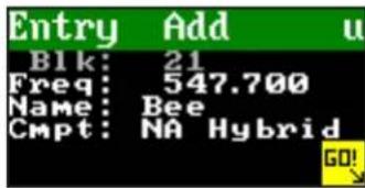
Group Edit:
Allows the user to add, edit, or delete entries within the available tuning groups. Use the UP or DOWN arrow buttons to highlight which group to edit, then press MENU/SEL. If the selected group is empty, "New Entry..." will be highlighted. Press MENU/SEL to create a new entry. Use MENU/SEL to move the cursor among the editable fields. For MHz and kHz, use the UP or DOWN buttons to select the desired numerical values.
With the Name field highlighted, use the UP or DOWN buttons to choose the desired letters or numbers, and the MENU/SEL button to move the cursor to the next slot in the name field. Up to 8 characters are available. When the name is complete, press the BACK button. Then, press MENU/SEL to move the cursor to the Compat Mode selection. Use the UP or DOWN buttons to select the desired compat mode for this entry.

NOTE: For any frequencies in a block overlap area (blocks 470/19, 23/606/24) and a Hybrid mode is selected, it is important to also define which block is desired for proper operation, otherwise there may be a pilot tone conflict.
Press MENU/SEL and "GO!" will appear at the lower right corner of the display. Press the DOWN button to save the entry.
Editing Existing Entries:
Editing group entries is done the same way they were created, with the exception of the "Del" (delete) box. To delete an entry, press MENU/SEL to navigate to the delete box, then use the UP or DOWN buttons to select or unselect, press MENU/SEL and "GO!" will appear at the bottom right. Press the DOWN button to complete.

Diversity:
Choose between: Vector or Frequency. Diversity modes safeguard against loss of audio signal caused by Multipath. If you choose Frequency, the system will ask you to calibrate. The calibration step is necessary for matching audio levels between channels for seamless results.
Using Diversity Modes
Two diversity reception modes are available:
- Vector Diversity uses two receiver front ends per audio channel, yielding two total channels.
- Frequency Diversity uses both receiver channels and two transmitters per audio channel. The second receiver will automatically be set to the same Compat Mode as CH1 when this diversity mode is selected.
Vector Diversity
Vector Diversity works by expressing the signal from each antenna in angle and magnitude (vector). This makes it possible to continuously rotate one of the vectors mathematically so the angles match and the signals can be combined constructively. In this way, all the energy that is available at both antennas is always fully contributing to the receiver's performance.
Frequency Diversity
Frequency Diversity differs from vector diversity in that it uses both receiver channels and two transmitters operating on different frequencies. The purpose of this mode is to have redundancy in the system for critical productions, such as live television, to guard against failures caused by dead batteries and multipath dropouts.
Frequency Diversity requires that the levels of the two audio channels to be closely matched to avoid audible level changes as the blending action takes place. In order for this blending to work properly, a special test mode helps to get the transmitter levels exactly matched.
Note: In Frequency Diversity mode, both transmitters must be the same type (usually the same model). The microphones must also be placed very close together to minimize comb filtering.

The DSR allows null testing with a special calibration mode as shown on the display. When the display shows "calibrate," it should be possible to achieve a null.
Calibration is automatically activated on selection of the Frequency Diversity mode, and automatically cancelled on exiting the diversity setup page. Calibration can be toggled on and off for testing but will revert to Operate mode on exiting the diversity setup page.
To prepare for operation in the Frequency Diversity mode, make the following adjustments:

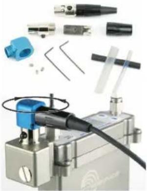
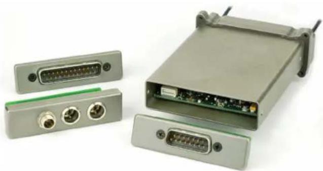
natural_image
Three black electronic devices with wireless cables and earbuds, no visible text or symbols-
Set up the transmitters according to their instructions. Verify that both transmitters are set to the same audio polarity, and set to the same input gain level. Turn them on to transmit, and verify that audio and RF signals are present at the receiver. Place the two microphone elements as closely together as possible, and place them where there is a steady source of sound. Pink noise from a loudspeaker, headphone, or smartphone is ideal. Make sure it is loud enough to modulate the receiver audio to the middle of the range on both channels.
-
Connect a headphone amplifier to one of the audio outputs on the DSR (in Frequency Diversity mode, the resulting blended audio is mirrored on both outputs). In the photograph, an MTCR is used. Plug a set of headphones into the amplifier jack to monitor the blended output.
-
In the "Calibrate" mode, the two receiver channels are placed out of polarity from each other. While listening to the blended output, adjust the gain control on one of the transmitters so that the audio level drops significantly (nulls) as the two channels
cancel each other. For the best performance in Frequency Diversity mode, adjust the mic gain up and down on one transmitter as described, listening for the deepest null.
- Once completed, Press the PWR/BACK button to exit this screen, which will automatically change from from "Calibrate" to "Operate". While still on the Diversity selection page, you can select "Calibrate" with the MENU/SEL button, then change to "Operate" by pressing the UP or DOWN buttons.
Pilot Bypass:
Allows the user to bypass the pilot tone on each channel while in a Hybrid compat mode and defeats the pilot tone squelch when on (no pilot tone is required). "Off" means that pilot tone must be present to allow audio output. This setting is compatibility mode dependent. If this option is not available for the mode you have chosen, the screen will show N/A.
WARNING: Without a carrier present (a transmitter on), the audio will be unsquelched noise.
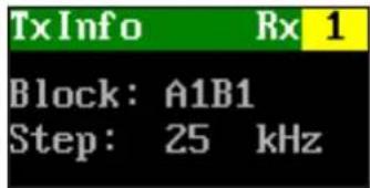
TxInfo:
Displays the Block and Step of the transmitter sync'd to each channel.
Audio Setup
Audio Level:
Allows user to set Audio Output Level and Tone per channel. These settings are Output Type dependent. If AES is chosen, there are no adjustments available.
Pressing MENU + UP when channel is highlighted will allow user to enable (or stop) 1kHz audio tone for level setting.


Output Type:
Allows user to choose output for each channel, analog or AES3.
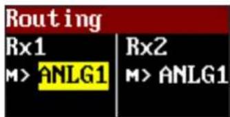
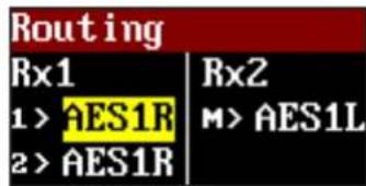
Routing:
Allows user to choose to send audio of Channel 1 or 2 as analog or digital to Output 1 or to Output 2 as analog only. The screens will look different depending on the Output Type that is chosen. M> refers to a Mono feed.
Smart NR:
Allows user to enable Smart Noise Reduction on either-receiver channel or both. Settings are: Off, Normal and Full. The default setting for digital compatibility modes is "Off." The default setting for hybrid modes is "Normal."
Talkback:
Allows user to enable the Talkback (TB) function on either receiver channels or both, to determine where the TB outputs are routed, and to select how the TB signals interact with the normal program audio on those outputs. If "Off" is selected for a receiver channel, then no Talkback function will occur on that channel, even if the transmitter's programmable switch is set to "TB" and activated. "Override" indicates that if a TB command comes from the transmitter, then the TB audio goes to the specified receiver output, and the normal audio from that channel is muted. "Mix" indicates that the TB audio and the standard audio routed to that receiver output will be mixed to that output. "TB Only" indicates that the normal audio routed to that output is muted, and only the TB audio will be present, and, only when the TB command is activated on the transmitter.
If AES3 output type is selected on Output 1, it is possible to keep the normal audio on both channels separate from any TB audio. Output 2, as mentioned, is mono and cannot be changed.
Polarity:
Allows user to set audio polarity of each channel as either positive or negative.
Compat Modes
Allows user to set compatibility mode per receiver channel. Available modes are: mono digital modes D2 and HDM (High Density Mode); stereo digital modes Duet channels 1-2, and DCHX (encrypted) channels 1-2; and mono Hybrid modes: NA Hybrid, NU Hybrid, EU Hybrid, and JA Hybrid. EU and JA modes are not available for Block 941.
IR & Keys Menu
The operations below depend on the compatibility mode selected and the transmitter used. The DSR has two-way IR for use with digital products (DBu, DBSM, etc.) and one-way IR for use with older IR-capable units such as LT and HMa. One-way protocol can only “Send Frequency.”
DSR LCD Menu Map
The menus presented on the LCD are arranged in a straightforward manner, with those that are likely to be used more often located at the top of the tree.
Main Menu Tree

flowchart
graph TD
    A["RF Setup"] --> B["Smart Tune"]
    B --> C["Frequency"]
    C --> D["Scan"]
    D --> E["Clear Scan Data"]
    E --> F["Group Edit"]
    F --> G["Diversity"]
    G --> H["PilotBypass"]
    H --> I["TxInfo"]
    I --> J["Audio Level"]
    J --> K["Output Type"]
    K --> L["Routing"]
    L --> M["Smart NR"]
    M --> N["Talkback"]
    N --> O["Polarity"]
    O --> P["Send All"]
    P --> Q["IR & Keys"]

    B --> R["Select option with arrow buttons"]
    R --> S["To select. ↑ ↓ ↑"]
    S --> T["Tx1 Range? AIB1 to select. ↑ ↓ ↑"]
    T --> U["Use arrow buttons to toggle through range options"]
    U --> V["To toggle. ↑ ↓ ↑"]
    V --> W["Scanning... 507,000 to pause scan"]
    W --> X["To select channel. ↑ ↓ to zoom view"]
    X --> Y["■ keep □ revert"]
    Y --> Z["After scan clears it automatically reverts to back the main menu tree."]

    F --> AA["Group Edit (empty)"]
    AA --> AB["Diversity Vector"]
    AB --> AC["PilotBypass OFF ON"]
    AC --> AD["TxInfo Block AIB1 Step 25 kHz"]
    AD --> AE["Select option with arrow buttons. If you choose Frequency, the system will ask you to Calibrate first. ↑ ↓ ↑"]
    AE --> AF["To select. ↑ ↓ ↑"]
    AF --> AG["PilotBypass OFF ON"]
    AG --> AH["View Rx1 or 2 with arrow buttons to return to menu list. ↑ ↓ ↑"]

    J --> AI["Audio Level HES ↑ ↓ ↑"]
    AI --> AJ["Output Type HES ANLG"]
    AJ --> AK["Routing RX1 ANLG1 RX2 ANLG2"]
    AK --> AL["Select option with arrow buttons to select. ↑ ↓ ↑"]
    AL --> AM["To select. ↑ ↓ ↑"]
    AM --> AN["Select option with arrow buttons to select. ↑ ↓ ↑"]
    AN --> AO["Routing RX1 ANLG1 RX2 ANLG2"]
    AO --> AP["Select option with arrow buttons to select. ↑ ↓ ↑"]
    AP --> AQ["To select. ↑ ↓ ↑"]
    AQ --> AR["Select option with arrow buttons to select. ↑ ↓ ↑"]

    M --> AS["Smart NR DOWN"]
    AS --> AT["Talkback ON"]
    AT --> AU["Polarity Pos Neg."]
    AU --> AV["Select option with arrow buttons to toggle. ↑ ↓ ↑"]

    P --> AW["Send Freq Sync 1 ---- Sync 2 ----"]
    AW --> AX["IR SYNC OK"]
    AX --> AY["Send All Sync 1 --- Sync 2 ---"]

    style A fill:#f9f,stroke:#333
    style B fill:#ccf,stroke:#333
    style C fill:#cfc,stroke:#333
    style D fill:#fcc,stroke:#333
    style E fill:#cff,stroke:#333
    style F fill:#ffc,stroke:#333
    style G fill:#fcc,stroke:#333
    style H fill:#fcc,stroke:#333
    style I fill:#fcc,stroke:#333
    style AJ fill:#fcc,stroke:#333
    style AK fill:#fcc,stroke:#333
    style AL fill:#fcc,stroke:#333
    style AM fill:#fcc,stroke:#333
    style AN fill:#fcc,stroke:#333
    style AO fill:#fcc,stroke:#333
    style AP fill:#fcc,stroke:#333
    style AQ fill:#fcc,stroke:#333
    style AR fill:#fcc,stroke:#333
DSR LCD Menu Map
flowchart
graph TD
    A["Get Freq"] --> B["Get All"]
    B --> C["Group Sync"]
    C --> D["Key Type"]
    D --> E["Make Key"]
    E --> F["Send Key"]
    F --> G["TXBat Icon"]
    G --> H["Auto On"]
    H --> I["Edit Names"]
    I --> J["Locale"]
    J --> K["Default"]
    K --> L["About"]

    subgraph Options
        direction TB
        M["To send key"] --> N["IR SYNC OK"]
        O["To get key."] --> P["IR SYNC OK"]
        Q["Select option with arrow buttons"] --> R["IR SYNC OK"]
        S["Down Arrow initiates sync."] --> T["IR SYNC OK"]
        U["Select option with arrow buttons"] --> V["IR SYNC OK"]
        W["Make Key? No Yes"] --> X["OK/Unlock Lock/Unlock Lock/Unlock Select option with arrow buttons to select. to select. to select. to select. to select. to select. to select. to select. to select. to select. to select. to select. to select. to select. to select. to select. to select. to select. to select. to select. to select. to select. to select. to select. to select. to select. to select. to select. to select. to select. to select. to select. to select. to select. To go back."]
    end

    style Options fill:#f9f,stroke:#333,stroke-width:2px
NOTE: You must position the transmitter's IR port directly in front of the DSR IR port, as closely as possible, to guarantee a successful sync.
Send Frequency
Sends operating frequency to the transmitter, each channel separately. Press the UP button to send the Channel 1 frequency, and the DOWN button to send the Channel 2 frequency. Success for digital compat modes is indicated on the receiver as "IR Sync OK." For digital modes, failure will be indicated on the receiver as "IR SYNC FAILED." For Hybrid compat modes, success will be indicated on the transmitter as "IR SYNC." Failure will be indicated on the transmitter as "CP Err" or "Block Mismatch" depending on the transmitter model and the source of the error.
Send All
(available only for digital compat modes)
Sends frequency, channel name/s, and Talkback state to the transmitter. Press the UP button to send the information from Channel 1, and the DOWN button to send the information from Channel 2. Since two-way IR Sync is only available for digital transmitters, "N/A" will be next to any channels that are in a Hybrid compatibility mode.
Get Frequency
(available only for digital compat modes)
Send or retrieve (get) frequency from the transmitter. Choose encryption type by pressing the UP and DOWN buttons. Select MENU/SEL to get frequency.
Get All
(available only for digital compat modes)
Retrieve (get) transmitter's frequency, Talkback state, and channel name. Press the UP button to get all and use for Channel 1. Press the DOWN button to get all and use for Channel 2. Since two-way IR Sync is only available for digital transmitters, "N/A" will be next to any channels that are in a Hybrid compatibility mode.
Group Sync
These functions allows you to send or get Tuning groups via IR sync to/from transmitters and receivers capable of using Groups (DSR, DCHR, DBSM, DBSMD, DPR, DPR-A). Use MENU/SEL button to navigate between the group choice and the send/get mode. With the group letter(s) highlighted, use the UP or DOWN buttons to select which frequency group (or all groups) to send or get. Then press the MENU/SEL button to select Send or Get. Use the UP or DOWN buttons to toggle between Send or Get. Then, press MENU/SEL again and "Go" will appear in the lower right corner. Press the DOWN button to complete the sync operation.
Encryption Key Management
The encryption system in Lectrosonics Digital modes D2, DCHX, and HDM may be configured in four different ways, determined by a parameter known as the Key Type. The four key types range from least secure but most convenient, to most secure but least convenient. Below are descriptions of the four Key Types and how they work.
- Universal: This is the default key type, the simplest to use, and the least secure. While encryption is technically being performed and a scanner or simple demodulator would not reveal the signal content, communications are not truly secure. This is because all Lectrosonics products employing the Universal key type use this same “universal” encryption key. With this key type selected, keys do not need to be created or exchanged, and wireless devices can be used without attention to the encryption feature.
- Shared: This is the easiest encryption mode to use while employing a uniquely generated key. This key type offers excellent security and considerable flexibility. Once a key has been created, it can be shared an unlimited number of times with any compatible device which, in turn, can also share the key. This is especially useful when multiple receivers may need to pick up various transmitters.
- Standard: The Standard key type offers enhanced security, at the cost of some complexity. Standard keys are “instance controlled”, which allows the hardware to protect against “differential attacks”. A Standard key can only be sent by the device that created it, and only up to 256 times. Unlike with Shared keys, devices receiving a Standard key cannot pass it on.
- Volatile: The Volatile key type is the most secure, and also the least convenient to use. Volatile keys behave identically to Standard keys, except that they are never stored. Equipment which is turned off while using a Volatile key will come back on with no key. If a key-generating device is left on, the key can be re-shared with units in the system that have lost their keys. Once all equipment having used a given Volatile key is powered off, that key is effectively destroyed. This may be required in some highly secure installations.
Encryption Keys
The DSR generates high entropy encryption keys to sync with encryption-capable transmitters. The user must select a key type and create a key in the DSR, and then sync the key with the transmitter.
- Begin by selecting a Key Type.
IR&Keys --> Key Type --> Universal, Shared, Standard or Volatile.
- Next, if using the Shared, Standard or Volatile key type, select MAKE KEY to generate a new key. Select "Yes" to confirm Make Key. IR&Keys --> Make Key.
NOTE: When Universal Key type is selected, there is no prompt to create key, as it is not necessary.
- A message will indicate that an Encryption Key has been created.
- Sync new key with transmitter (see Send Key). The transmitted audio will then be encrypted with the new key.
Send Key
Select SEND KEY to transfer the encryption key to any compatible transmitters or, in Shared key policy, additional receivers. Success will be indicated by the message “Encryption Key Sent” on the receiver display, and “Encryption Key Received” on the transmitter display. IR key transfer failure will be indicated by the message “IR Sync Failed” on the receiver display.
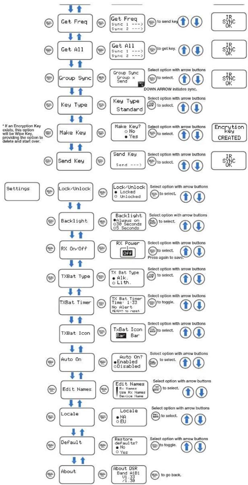
Settings Menu
Lock/Unlock
The user can lock or unlock the receiver. In Locked condition, the menus and settings can be browsed but not changed. Attempting to change a setting or power off the unit while in the locked condition causes the message "Settings Locked" to appear on the screen. The Lock/Unlock condition will persist through battery changes or external power being removed.
Backlight
Controls the display backlight timeout interval, following-the last button push. Choose from always on, 30 seconds, or 5 seconds. The backlight will automatically come on with low battery warnings.
Rx On/Off
Turns the power to each channel on or off. Use MENU/SEL to set and move the cursor and the UP and DOWN buttons to change values, then MENU/SEL to save and move to the next channel.
TxBat Type
Set the battery type for each transmitter channel. Note that for digital transmitters, the battery type is set in the transmitter and thus if the transmitter is not on, "no link" will show on that receiver channel. Use MENU/SEL to toggle between Channel 1 and Channel 2, and then use the UP and DOWN buttons to change the battery type settings for those channels (depending on compat mode)
TxBatt Timer
Set transmitter battery timer alerts for each channel. Choose to enable/disable alert, set time in hour and minutes and reset timer. Use MENU/SEL to set and move the cursor and the UP and DOWN buttons to change values. To re-set the timer for the selected channel, press the MENU/SEL and UP buttons together.
TxBatt Icon
Choose between Bar, Volt or Time. Use MENU/SEL to select the channel and the UP and DOWN buttons to change values.
AutoOn
Press the UP or DOWN buttons to enable or disable the auto power on function.
Edit Names
Allows the user to change the names of the Receiver Channels 1 and 2, to display the names and to change the name of the device itself (from the default "DSR" to, say, a talent name). Use MENU/SEL to select the channel and the UP and DOWN buttons to change values.
Locale
The locale should be chosen based on the region where the receiver is being used, relative to the band the unit was designed to operate within. The following options are available:
- NA: (default setting) represents the North American locale and prevents operation in the Astronomical Band (from 608 to 614 MHz). It allows tuning from 470.100 up to 607.950 MHz on A1B1 and from 537.600 to 607.950 MHz and 614.400 to 691.175 MHz on B1C1.
- EU: represents the European locale, and tunes at 470.100 up to 614.375 MHz on A1B1 and from 537.600 to 691.175 MHz on B1C1.
- AU: represents the Australian locale, and tunes to 520.000 to 614.375 MHz on A1B1, and from 537.600 to 691.175 MHz on B1C1.
Default
This setting restores the unit to factory settings.
About

Displays general information about the DSR, including band, microcontroller and FPGA versions. The microcontroller version number is the first
number under the band, followed by the FPGA version number after the forward slash.
Antenna Mounting and Orientation
A variety of accessories are available to enable various mounting options. For maximum operating range, the antennas should be vertical and above the camera and other equipment. The AMJ Rev. A antenna is jointed so the whips can be oriented vertically.

Do not mount the receiver so the antennas will be next to another piece of equipment nor oriented horizontally

natural_image
Exterior view of a black industrial device with two antennas and a display unit (no visible text or symbols)The receiver provides stand-alone operation with the battery sled adapter and mounting sleeve. It can be mounted in any position with Velcro, or in horizontal and vertical positions using the mounting foot, or mounted directly onto a 1/4-20 threaded stud on a tripod.
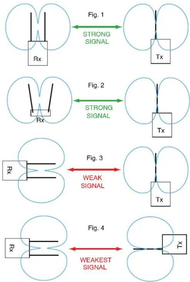
The diagrams below depict typical orientations of transmitter and receiver antennas in field production and how the RF signal transfer is affected. Maximum sensitivity is perpendicular to the whip, so an ideal setup is shown in Fig. 1 and Fig. 2 where the receiver is mounted in either a vertical or horizontal position with the whips oriented vertically.
Fig. 3 depicts the receiver and antenna whips oriented horizontally, which places the null of the receiver antenna pattern pointing toward the transmitter. The result, of course, is a weak signal entering the receiver.
Fig. 4 depicts the worst setup where the nulls in both receiver and transmitter patterns face one another.
The transmitter antenna whips can point upward as shown in these diagrams, but they will work just as well with the whip pointing downward. Mount the transmitter so that the whip is vertical and not in direct contact with the wearer's body or metallic objects in clothing and costuming.
flowchart
graph TD
    A["Stage 1: RX/Rx signal"] -->|Strong Signal| B["Tx/Tx"]
    C["Stage 2: RX/Rx signal"] -->|Strong Signal| D["Tx/Tx"]
    E["Stage 3: RX/Rx signal"] -->|Weak Signal| F["Tx/Tx"]
    G["Stage 4: RX/Rx signal"] -->|Weakest Signal| H["Tx/Tx"]
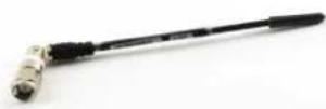
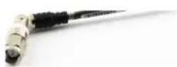
AMJ Jointed Antenna
The AMJ antenna is a general purpose design with a hinged joint that pivots in both directions for positioning the whip at any desired angle. The pivot allows the whips to be oriented vertically regardless of the mounting position of the receiver.
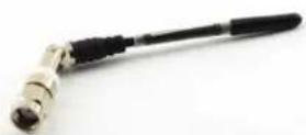
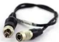
natural_image
Close-up of two metallic USB connectors with black leads, one with a plus symbol and the other with a separate metal connector (no text or labels visible)The hinged joint pivots in both directions
SNA600A Omni Dipole Antenna
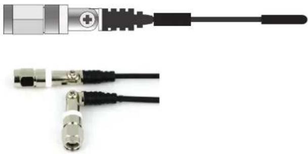
The SNA600a antenna is a versatile tool for use with wireless microphone receivers or IFB transmitters. The center frequency of its 100 MHz bandwidth is tunable from 550 to 800 MHz; however, the roll-off above and below this band is gradual. The SNA600a measures lower than a 2:1 SWR (Standing Wave Ratio) from 465 MHz to 850 MHz when the antenna arms are fully extended.
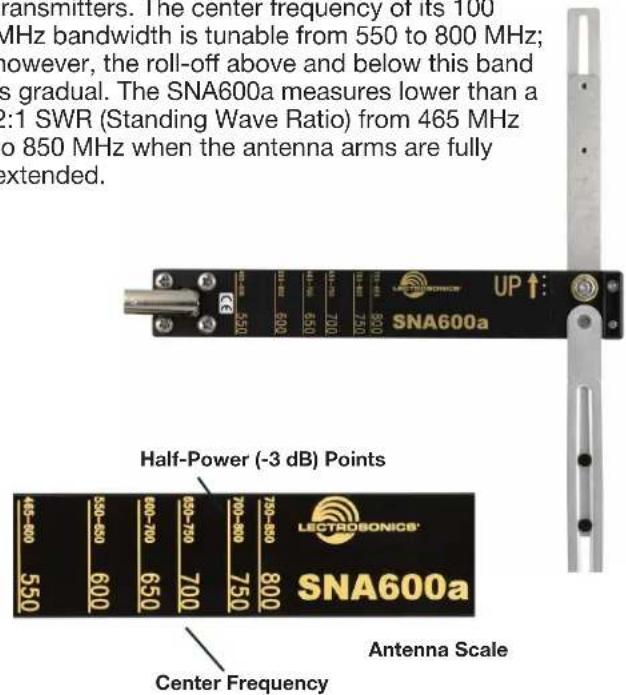
A "bendable" mounting strap is included that allows vertical orientation on a variety of surfaces. Several other adapters are also available for temporary or fixed installations.
natural_image
Pure technical line drawing of a mechanical component with no text or symbolsThis is one example of using two splitters to feed two receivers.

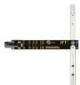
Use Lectrosonics P/N 21770 BNC (F) to SMA (M) adapter; Pomona P/N 4290
Antenna/Block Reference Table
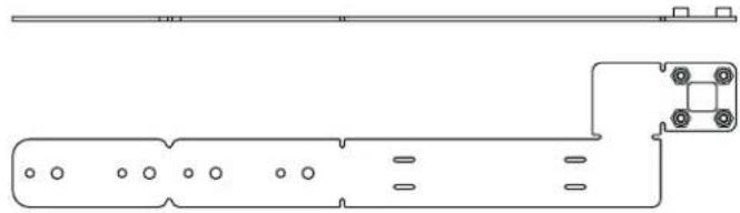
The two AMJ whip antennas supplied with the receiver are factory cut to specific frequency blocks as shown in the table below. A colored cap and label are used on blocks 20 through 26, and a black cap and label are used on the other blocks to denote the frequency range of each model.
The chart is useful for fabricating an antenna from coaxial cable or other materials, or for identifying the frequency of an antenna that is not marked. The lengths shown are specifically for the AMJ whip antenna with a SMA connector, as determined by measurements with a network analyzer. The optimal length of the element in other designs will likely be different than those shown in this table, but since the bandwidth is typically wider than the specified block, the exact length is not critical for useful performance in whip, dipole and coaxial designs.

| FREQUENCY | |||||
| BLOCK | RANGE | CAP COLOR | ANTENNA WHIP LENGTH | ||
| A1 | 470 47 | 0.100 - 495.600 Black | w/ Label 5.47" 141.2 mm | ||
| 19 486 | .400 - 511.900 Black w/ Label 5.19" 133.9 mm | ||||
| 20 512 | .000 - 537.500 Black w/ Label 4.95" 126.2 mm | ||||
| B1 | 21 537 | .600 - 563.100 Brown | 4.73" 119.6 mm | ||
| 22 563 | .200 - 588.700 Red 4.47" 113.8 mm | ||||
| 23 588 | .800 - 614.300 Orange | 4.23" 108.5 mm | |||
| C1 | 24 614 | .400 - 639.900 Yellow | w/Label 4.07" 103.4 mm | ||
| 25 640 | .000 - 665.500 Green w/Label 3.87" 98.3 mm | ||||
| 26 665 | .600 - 691.100 Blue w/ Label 3.68" 93.5 mm | ||||
| 941/961 | 941 94 | 1.525 - 959.825 Black | w/Label 2.53" 64.3 mm | ||
| 961 96 | 1.100 - 1014.900 Black w/Label 2.53" 64.3 mm | ||||
Note: Not all Lectrosonics products are built on all of the blocks covered in this chart.
Lay uncut antenna on this template and cut to length for the desired frequency block
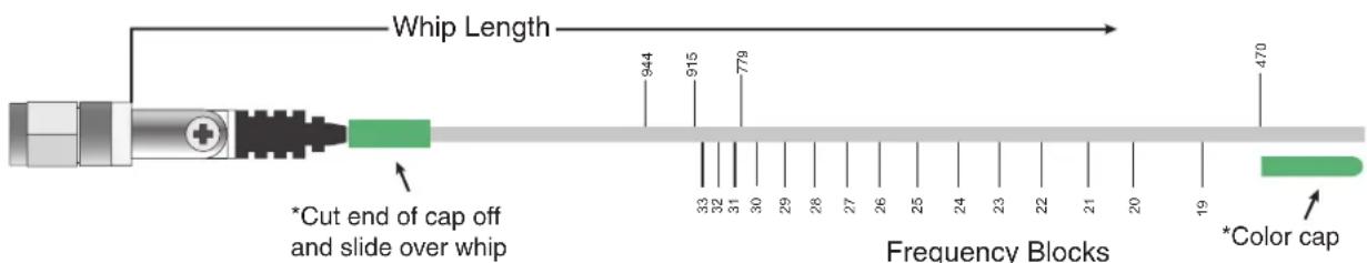
Trim the end of the color cap and slide the remaining sleeve over the whip - OR - Glue color cap onto the end
Note: Check the scale of your printout. This line should be 6.00 inches long (152.4 mm).
Interference Management Multi-channel System Checkout
Interference can result from a wide variety of sources including TV station signals, other wireless equipment in use nearby, or from intermodulation within a multi-channel wireless system itself. Regardless of how the frequencies were coordinated, a final checkout procedure is always a good idea.
Scanning with the RF spectrum analyzer built into the DSR system will identify external RF signals, but it does not address the compatibility of the selected frequencies.
The pre-coordinated frequencies address in-system intermodulation, but obviously cannot take into account RF signals from external sources that may be present in the location where the system will be operating.
1. Set up the system for testing.
Place antennas in the position in which they will be used and connect to the receivers. Place transmitters about 3 to 5 feet apart, about 25 to 30 feet from the receiver antennas. If possible, have all other equipment on the set, stage or location turned on as well, especially any mixing or recording equipment that will be used with the wireless system.
2. Set all receivers on clear channels.
Turn on all receivers, but leave the transmitters off. Observe at the RF signal strength indicator for each receiver module. If a signal is present, change the frequency to a clear channel where no signal is indicated. If a completely clear channel cannot be found, select the frequency with the lowest RF level indication. Once all receiver modules are on clear channels, go to step 3.
3. Turn each transmitter on one at a time.
Start with all transmitters turned off. As you turn on each one, look at the matching receiver to verify a strong RF signal is received. Then, look at the other receivers and see if one of them is also picking up the signal. Only the matching receiver should indicate a signal. Change frequencies on either system slightly until all channels pass this test, then check again to see that all channels are still clear as done in step 2.
4. Turn each transmitter off one at a time.
With all transmitters and receivers turned on, turn each transmitter off one at a time, in turn, and look at the RF level indicator on the matching receiver module. The RF level should disappear or drop to a very low level. If it does not, change frequency on that receiver and transmitter and try it again. When a clear frequency is found, turn the transmitter on and move on to the next channel.
IMPORTANT: Any time a frequency is changed on any of the systems in use, you must start at the beginning and go through this procedure again for all systems. With a little practice, you will be able to do this quickly and save yourself some “multi-channel grief.”
Firmware Update Instructions
The DSR is supported in the current version of Wireless Designer via USB connection (the USB connector under the top panel of the receiver must be used. USB connectors on the back panel, for instance DSREXTUSB cannot be used for firmware updates.
Be aware of the following when preparing to connect your DSR to Wireless Designer via USB:
The DSR must have the micro and FPGA firmware both updated to the most recent versions: v1.33 (micro) or v.1.30 (FPGA) or higher. Wireless Designer version must be at least 2.0.50 for macOS, or version 2.0.52 or higher for Windows. These are available on our Support website at: https://www.lectrosonics.com/wireless-designer.html.
Once the USB is connected to the DSR top panel connector and to the computer, launch Wireless Designer and use the Update Firmware pull-down menu under the Connect (live) header. Choose the device from the list, in this case, DSR. Follow the on-screen instructions and use the .update file downloaded from the Lectrosonics web site under Support>Firmware>DSR.

Supplied Parts and Accessories
| Ships With | |
| A1B1 | (2) AMJ19; (2) AMJ22 |
| B1C1 | (2) AMJ22; (2) AMJ25 |
| 941 (2) AMJ944 | |
| 961 (2) AMJ961 | |
AMJ19
Swivelling Whip Antenna with Standard SMA Connector, Block 19. Shipped with A1B1 units only.
AMJ22
Swivelling Whip Antenna with Standard SMA Connector, Block 22. Shipped with A1B1 and B1C1 units.

AMJ25
Swivelling Whip Antenna with Standard SMA Connector, Block 25. Shipped with B1C1 units only.
AMJ944
Swivelling Whip Antenna with Standard SMA Connector. Shipped with 941 units only.
AMJ961
Swivelling Whip Antenna with Standard SMA Connector. Shipped with 961 units only.

Optional Parts and Accessories
21770
Male SMA to Female BNC Adapter.

21926
USB cable for firmware updates.

ACOAXTX
Antenna, Coaxial, SMA Plug for Transmitters, Specify Block.

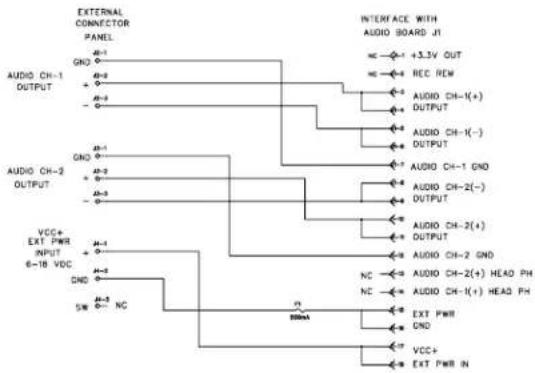
DSREXTUSB Adapter
This kit includes an output and power panel with two TA3 male balanced output pairs, 3 mounting screws (PN 28615) and a locking Hirose-4 DC power jack. A USB-C jack allows for connection of the DSR to Wireless Designer. Firmware updates must be done with the USB Micro B connector on the top panel of the unit. Power cord not included.
SNA600A Omni Dipole Antenna
Versatile Antenna, 100 MHz Bandwidth tunable from 550 to 800 MHz. Includes mounting screws and bracket. Requires SMA to BNC Adapter.
PS200A
Power Cable, 15 in., Hirose4 to LZR
PS2200A
Power Cable, 12 in., Hirose4 to Dual LZR.

SREXT
Adapter kit for SR/DSR receivers, two TA3 audio output jacks, locking power connector, includes 6' power cord. Has spare mounting screws in dummy holes in adapter.

SRSNY
Mounting adapter for SR/DSR receivers for Sony cameras includes Unislot mounting kit, Superslot compatible.

SRSUPER
Mounting adapter for SR/DSR receivers includes Unislot mounting kit, Superslot compatible.

SRBATTSLED TOP
A “battery sled” that positions the battery on top of the receiver for mounting on the top of the camera with the LCD and rear panel nomenclature oriented correctly.
SRBATTSLED BOTTOM
A “battery sled” that positions the battery on the bottom of the receiver for mounting on the bottom of the camera with the LCD and rear panel nomenclature oriented correctly.
Do not use SR9VBP accessory with DSR receiver - it does not supply enough current for this receiver.
SRHARNESS
Output/power adapter panel for SR/DSR receivers. Strain relief attached cables with stripped, tinned ends, 5 feet, 8 inches.

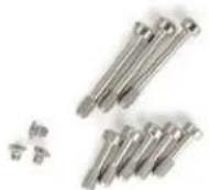
SRUNISCREWKIT
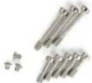
(also for SUPERSLOT)
Contains:
3 - #28862 (longest)
5 - #28864 (mid-length)
3 - #28869 (shortest)*
* For Housing
UMCWBD-L
Rack mount with power and RF signal distribution for four diversity compact receivers in a single rack space. Requires mounting/DC power kit (below) per receiver.
ZS-UMC-DSR4-DSR-KIT
Kit for DSR4/DSR mounting. Snap-in bezel. Screw kit. Mid-mounting plastic frame. Thread-locking "LZR" DC power tail.
ZS-UMC-DSR4-HIROSE4-KIT
Kit for DSR4 mounting with Hirose 4 power. Snap-in bezel. Screw kit. Mid-mounting plastic frame. Hirose 4-pin DC power tail.
Audio Output Cables and Connectors
MCSR/5PXLR5P
Right angle TA5F plug to 5-pin XLR; balanced outputs; 25 inches long. For TA5M output jacks.

MCSR/5PXLR2
Right angle TA5F plug to two 3-pin XLR; balanced outputs; 20 inches long. For TA5M output jacks.

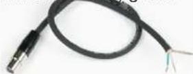
MCSRPT
12 inch long TA3 female to stripped and tinned wires for balanced output. PIN 1: Shield / PIN 2: Audio (+) white/PIN 3: Audio (-) green.
PIN 3: Audio (-) green
MCSRXLR
12 inch long TA3 female to XLR male 3-pin for balanced output. PIN 1: Shield / PIN 2: Audio (+) / PIN 3: Audio (-)

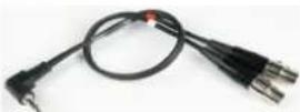
MCSRTRS
Male 3.5 mm TRS plug to two female TA3 (mini XLR) connectors for dual channel use, unbalanced.
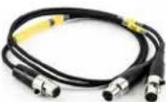
MCTA5TA3F2
Audio cable for portable digital receivers, TA5F to two TA3F connectors, 18" cable. For two analog balanced receiver outputs, or two AES digital pairs (four audio channels), into mixer or recorder inputs.
MCTA5TPT2
Audio cable for portable digital receivers, TA5F to two stripped and tinned ends, 18" cable. For two analog balanced receiver outputs, or two AES digital pairs (four audio channels).

RATPAC Adapter Kit
Adapter kit to build either a 3-pin or 5-pin TA Series right angle connector. Includes standard 5-pin connector, modified 3-pin insert and backshell, aluminum right angle housing, strain relief tubing, set screws and wrenches.
natural_image
Exploded view of industrial mechanical components including a blue plastic fitting, black plastic parts, and a metallic base (no visible text or symbols)The 5-pin RATPAC right angle connector is designed for the front panel output jack. The 3-pin version is designed for the rear panel outputs on the receiver.
The connector can be rotated during assembly to exit the cable in the desired direction. See instructions included with the RATPAC kit.
External Power Supplies
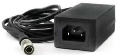
DCR15/4AU
Power supply with a standard C14 inlet and locking LZR coaxial output connector; 100-240 VAC in, 15 VDC regulated output; 4A max.

natural_image
Black rectangular electronic device with power connector and cable, no visible text or symbols on bodyDCR15/1A8U-H
Power supply with a standard C14 inlet and locking Hirose 4-pin output connector; 100-240 VAC in, 15 VDC regulated output; 1.8A max. Use with DSREXTUSB.
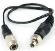
natural_image
Black electronic device with coiled cable and connector (no visible text or symbols)External Power Cables
21747

Locking LZR style plug to stripped and tinned; 6 feet long.
21746

natural_image
Coiled black cable with metallic connector and red wire, no visible text or symbolsLocking LZR style plug to stripped and tinned; 12 inches long.
PS200A
Hirose 7-4 pin to LZR type locking plug, 12" long.
21425
6 ft. long non-locking power cord; coaxial to stripped & tinned leads. Coaxial plug: ID-.080"; OD-.218"; Depth-.5".
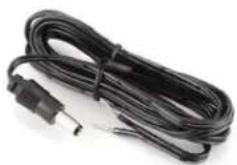
natural_image
Coiled black cable with a small plug, isolated on white background (no text or symbols)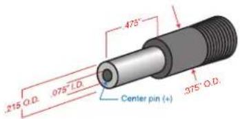
21472
6 ft. long non-locking power cord; coaxial to stripped & tinned leads. Right angle coaxial plug: ID-.075"; OD-.218"; Depth-.375"
natural_image
Coiled black cable with connectors, no visible text or symbols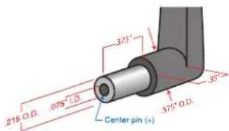
21586
DC16A pigtail power cable, stripped & tinned. LZR Thread lock collar.
natural_image
Coiled black cable with two metallic connectors (no text or symbols visible)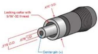
Camera Slot Adapters
SRSUPER

natural_image
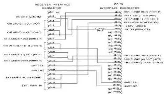
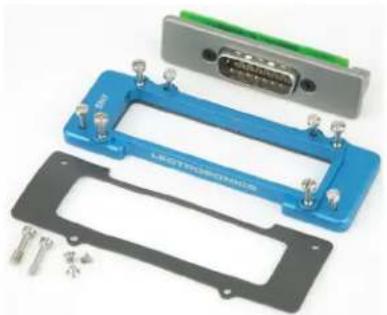
Electronic component housing with blue plastic casing and metallic connectors, no visible text or symbolsAdapter kit for Un- islot camera slots such as those pro- vided on Ikegami and Panasonic cameras, and SuperSlot docks like the SL-2 by Sound Devices. Includes bezel, hard- ware and rear panel DB25 connector wired for power and audio connections.
flowchart
graph TD
    A["RECEIVER INTERFACE CONNECTOR"] --> B["FX ON (REMOTE)"]
    A --> C["CHI AUDIO (OUT HOT)"]
    A --> D["CHI AUDIO (-) OUT (COOL)"]
    A --> E["CHI AUDIO AND (SHILLI)"]
    A --> F["CHI AUDIO (-) OUT (COOL)"]
    A --> G["CHI AUDIO (-) CHI (PH1)"]
    A --> H["CHI AUDIO AND (PH1H)"]
    A --> I["LATT TX"]
    A --> J["LUNT RX"]
    A --> K["EXTERNAL POWER AND"]
    A --> L["EST PWR IN"]

    M["DB 25 INTERFACE CONNECTOR"] --> N["CHI AUDIO AND (PH1H)"]
    M --> O["CHI AUDIO (-) OUT (COOL)"]
    M --> P["CHI AUDIO (+) OUT (HOT)"]
    M --> Q["CHI AUDIO (-) OUT (COOL)"]
    M --> R["LATT TX"]
    M --> S["LUNT RX"]
SRSNY
Mounting adapter for SR/DSR receivers for Sony cameras. Includes bezel, hardware and rear panel DB15 connector wired for power and audio connections.
natural_image
Electronic component assembly with blue and black plastic parts, no visible text or symbols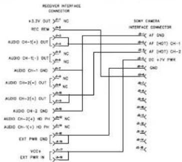
flowchart
graph TD
    A["+3.2V OUT"] --> B["REC REM"]
    C["+3.2V OUT"] --> D["REC REM"]
    E["+3.2V OUT"] --> F["REC REM"]
    G["+3.2V OUT"] --> H["REC REM"]
    I["+3.2V OUT"] --> J["REC REM"]
    K["+3.2V OUT"] --> L["REC REM"]
    M["+3.2V OUT"] --> N["REC REM"]
    O["+3.2V OUT"] --> P["REC REM"]
    Q["+3.2V OUT"] --> R["REC REM"]
    S["+3.2V OUT"] --> T["REC REM"]
    U["+3.2V OUT"] --> V["REC REM"]
    W["+3.2V OUT"] --> X["REC REM"]
    Y["+3.2V OUT"] --> Z["REC REM"]
    AA["+3.2V OUT"] --> AB["REC REM"]
    AC["+3.2V OUT"] --> AD["REC REM"]
    AE["+3.2V OUT"] --> AF["REC REM"]
    AG["+3.2V OUT"] --> AH["REC REM"]
    AI["+3.2V OUT"] --> AJ["REC REM"]
    AK["+3.2V OUT"] --> AL["REC REM"]
    AM["+3.2V OUT"] --> AN["REC REM"]
    AO["+3.2V OUT"] --> AP["REC REM"]
    AQ["+3.2V OUT"] --> AR["REC REM"]
    AS["+3.2V OUT"] --> AT["REC REM"]
    AU["+3.2V OUT"] --> AV["REC REM"]
    AW["+3.2V OUT"] --> AX["REC REM"]
    AY["+3.2V OUT"] --> AZ["REC REM"]
    BAY["+3.2V OUT"] --> BB["REC REM"]
    BCY["+3.2V OUT"] --> BD["REC REM"]
    BEZ["+3.2V OUT"] --> BF["REC REM"]
    BGZ["+3.2V OUT"] --> BH["REC REM"]
    BIYZ["+3.2V OUT"] --> BJ["REC REM"]
    BKZLZ["+3.2V OUT"] --> BL["REC REM"]
    BMZLZ["+3.2V OUT"] --> BN["REC REM"]
    BOZLZ["+3.2V OUT"] --> BP["REC REM"]
    BCAZLZ["+3.2V OUT"] --> CA["REC REM"]
    CBZLZ["+3.2V OUT"] --> CD["REC REM"]
    CEZLZ["+3.2V OUT"] --> CF["REC REM"]
    DGZLZ["+3.2V OUT"] --> DH["REC REM"]
    DIZLZ["+3.2V OUT"] --> DJ["REC REM"]
    DKZLZ["+3.2V OUT"] --> DL["REC REM"]
    DMZLZ["+3.2V OUT"] --> DJ
    DBZLZ["+3.2V OUT"] --> DV["REC REM"]
    DWZLZ["+3.2V OUT"] --> DW
    BXZLZ["+3.2V OUT"] --> BX
    BYZLZ["+3.2V OUT"] --> BY
    ZBZLZ["+3.2V OUT"] --> Z
    CAZLZ["+3.2V OUT"] --> CA
    DBZLZ["+3.2V OUT"] --> DB
    DCZLZ["+3.2V OUT"] --> DC
    DVZLZ["+3.2V OUT"] --> DV
    BWZLZ["+3.2V OUT"] --> BW
    BXZLZ["+3.2V OUT"] --> BX
    BYZLZ["+3.2V OUT"] --> BY
    ZBZLZ["+3.2V OUT"] --> ZB
    CAZLZ["+3.2V OUT"] --> CA
    DBZLZ["+3.2V OUT"] --> DB
    DCZLZ["+3.2V OUT"] --> DC
    DWZLZ["+3.2V OUT"] --> DW
    BXZLZ["+3.2V OUT"] --> BX
    ZBZLZ["+3.2V OUT"] --> ZB
    CAZLZ["+3.2V OUT"] --> CA
    DBZLZ["+3.2V OUT"] --> DB
    DCZLZ["+3.2V OUT"] --> DC
    DWZLZ["+3.2V OUT"] --> DW
    BXZLZ["+3.2V OUT"] --> BX
SRUNISCREWKIT
(also for SUPERSLOT)
Contains:
3 - #28862 (longest)
5 - #28864 (mid-length)
3 - #28869 (shortest)*
* For Housing
Installing Camera Slot Adapters
SRSUPER Adapter*

natural_image
Close-up of a metallic electronic device with blue base labeled 'LECTROSONICS' (no readable text beyond label)Thread two short screws through the recessed tabs on the adapter and slide it onto the receiver housing. Thread two short screws through the tabs on the receiver flange as shown.

natural_image
Close-up of a metallic industrial sensor or sensor device with blue base (no visible text or symbols)On the opposite side, thread two long screws through the tabs on the receiver flange, then align them with the tabs on the adapter.

natural_image
Close-up of a mechanical assembly with blue and gray components, no visible text or symbolsSlide the adapter up and tighten the retaining screws to secure it to the receiver flange.
The four lower screws attach to the camera body.
* SRSNY is installed in the identical fashion.
IMPORTANT WARNING
The DSR is a high current receiver that should not be used in a slot-mount camera without double checking available current from the camera. The DSR draws nearly 400mA at 7VDC. DO NOT drop it in the camera to "see what happens." Consult with your camera manufacturer FIRST before attempting to use this receiver in-slot.
The DSR is intended for use in slot devices which can supply enough current safely and without damage to fuses or poly-fused circuits.
Lectrosonics will not be responsible for damages that may result from using this receiver in a slot mount that cannot supply adequate current.
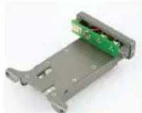
Rear Panel and Adapters
Several different panel adapters are available to configure the receiver for use with popular camera slots and for stand-alone use. The adapters are retained by two screws through the side panel of the housing, making them easy to install.
natural_image
Exterior view of a gray electronic device with multiple ports and connectors (no visible text or symbols)Power and audio connections are made through mating connectors on the adapter and receiver circuit boards.

natural_image
Two electronic devices showing internal components: one with a green circuit board and a close-up of its internal wiring (no visible text or symbols)Installing Rear Panel Adapters
Installation of the rear panel output/power adapters is the same for all models.

natural_image
Exterior view of a silver electronic device with three ports and directional arrows indicating orientation (no text or symbols visible)Panels are held in place by two phillips head screws on the sides of the housing.

natural_image
Close-up of a green electronic device with internal components, showing a close-up view of a connector (no visible text or symbols)Connections between the panel and main circuit board are made via miniature mating connectors.

natural_image
Close-up of a gray electronic device with three ports and a green internal component (no visible text or symbols)Align the mating connectors and slide the panel straight into the housing until the screw holes align with the housing.
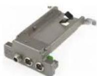
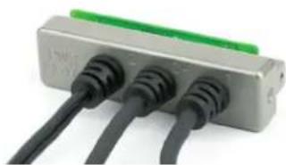
Adapters for Stand-Alone Use

natural_image
Coiled black cable with three connected ports and a green connector, no visible text or symbolsFor stand-alone use, this kit includes a rear panel with two TA3 male jacks for the balanced outputs and a power jack with an LZR locking connector. Trim the power cable to the desired length.
flowchart
graph TD
    A["EXTERNAL CONNECTOR PANEL"] --> B["OUTPUT"]
    B --> C["AC-1"]
    B --> D["AC-2"]
    B --> E["AC-3"]
    B --> F["AC-4"]
    B --> G["AC-5"]
    B --> H["AC-6"]
    B --> I["AC-7"]
    B --> J["AC-8"]
    B --> K["AC-9"]
    B --> L["AC-10"]
    B --> M["AC-11"]
    B --> N["AC-12"]
    B --> O["AC-13"]
    B --> P["AC-14"]
    B --> Q["AC-15"]
    B --> R["AC-16"]
    B --> S["AC-17"]
    B --> T["AC-18"]
    B --> U["AC-19"]
    B --> V["AC-20"]
    B --> W["AC-21"]
    B --> X["AC-22"]
    B --> Y["AC-23"]
    B --> Z["AC-24"]
    B --> AA["AC-25"]
    B --> AB["AC-26"]
    B --> AC["AC-27"]
    B --> AD["AC-28"]
    B --> AE["AC-29"]
    B --> AF["AC-30"]
    B --> AG["AC-31"]
    B --> AH["AC-32"]
    B --> AI["AC-33"]
    B --> AJ["AC-34"]
    B --> AK["AC-35"]
    B --> AL["AC-36"]
    B --> AM["AC-37"]
    B --> AN["AC-38"]
    B --> AO["AC-39"]
    B --> AP["AC-40"]
    B --> AQ["AC-41"]
    B --> AR["AC-42"]
    B --> AS["AC-43"]
    B --> AT["AC-44"]
    B --> AU["AC-45"]
    B --> AV["AC-46"]
    B --> AW["AC-47"]
    B --> AX["AC-48"]
    B --> AY["AC-49"]
    B --> AZ["AC-50"]
    B --> BA["AC-51"]
    B --> BB["AC-52"]
    B --> BC["AC-53"]
    B --> BD["AC-54"]
    B --> BE["AC-55"]
    B --> BF["AC-56"]
    B --> BG["AC-57"]
    B --> BH["AC-58"]
    B --> BI["AC-59"]
    B --> BJ["AC-60"]
    B --> BK["AC-61"]
    B --> BL["AC-62"]
    B --> BM["AC-63"]
    B --> BN["AC-64"]
    B --> BO["AC-65"]
    B --> BP["AC-66"]
    B --> BQ["AC-67"]
    B --> BR["AC-68"]
    B --> BS["AC-69"]
    B --> BT["AC-70"]
    B --> BU["AC-71"]
    B --> BV["AC-72"]
    B --> BW["AC-73"]
    B --> BX["AC-74"]
    B --> BY["AC-75"]
    B --> BZ["AC-76"]
    B --> CA["AC-77"]
    B --> CB["AC-78"]
    B --> CC["AC-79"]
    B --> CD["AC-80"]
    B --> CE["AC-81"]
    B --> CF["AC-82"]
    B --> CG["AC-83"]
    B --> CH["AC-84"]
    B --> CI["AC-85"]
    B --> CJ["AC-86"]
    B --> CK["AC-87"]
    B --> CL["AC-88"]
    B --> CM["AC-89"]
    B --> CN["AC-90"]
    B --> CO["AC-91"]
    B --> CP["AC-92"]
    B --> CQ["AC-93"]
    B --> CR["AC-94"]
    B --> CS["AC-95"]
    B --> CT["AC-96"]
    B --> CU["AC-97"]
    B --> CV["AC-98"]
    B --> CW["AC-99"]
    B --> CX["AC-100"]
SRHARNESS
Ideal for use in portable bag systems. Two balanced output cables and the power cable are 5 feet, 8 inches long. Cut the cables to the desired length and terminate as needed.
natural_image
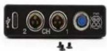
Close-up of a gray electronic device with three black cables and a green connector (no visible text or symbols)DSREXTUSB Adapter
This kit includes an output and power panel with two TA3 male balanced output pairs, 3 mounting screws (PN 28615) and a locking Hirose-4 DC power jack. A USB-C jack allows for connection of the DSR to Wireless Designer. Firmware updates must be done with the USB Micro B connector on the top panel of the unit. Power cord not included.

natural_image
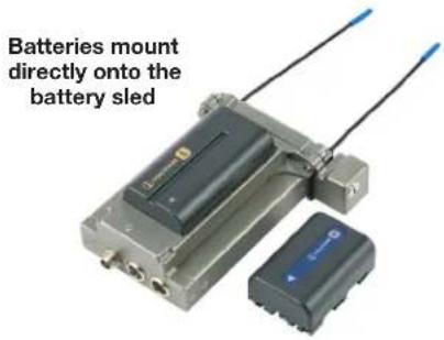
Close-up of a black electronic device panel with labeled ports (no readable text or symbols beyond labels)Battery Adapters and Mounting Kits
Battery sled adapters configure the receiver for standalone use or to provide battery backup power. Several options are available:
- SRBATTSLEDTOP
• SRBATTSLEDBOTTOM
• SR9VBP (inserts into the SLED adapters)
WARNING: Risk of explosion if the battery is replaced by an incorrect type.
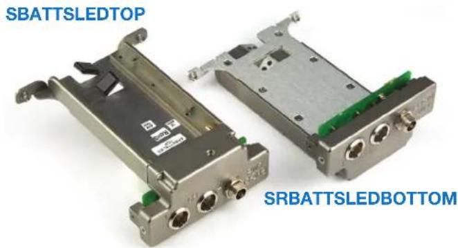
natural_image
Two electronic device modules labeled SBATTSLEDTOP and SRBATTSLEDBOTTOM, showing internal components with connectors and ports (no readable text beyond labels)The battery sled adapters accept L and M type video camera rechargeable batteries and the optional SR9VBP 9 volt battery case.
The battery sled adapters do not include charging circuitry. Batteries must be charged with their respective chargers. The adapters include an integral circuit that automatically selects between the battery and the external source, whichever delivers the highest voltage.
Installing the SRBATTSLED
Orient the battery sled so that the PCB connectors will mate when the sled is inserted.

Slide the battery sled adapter into the end of the SR and gently seat it into place with the rear panel flush with the housing.

natural_image
Exterior view of a gray industrial electronic device with multiple ports and wiring (no visible text or symbols)Install and tighten the two side panel and two top panel screws as indicated by the arrows.

Battery Life
- The DSR receiver operating time with a NP-F570 slim L series battery at full charge is approximately 7.5 hours.
SRSLEEVE mounting adapter
This sleeve is supplied with Velcro swatches for mounting an SR Series receiver on a flat surface of camera, cart, rack, etc. The sleeve is sized and lined for a snug fit in a vertical or horizontal position.

natural_image
Two black plastic components: a U-shaped bracket and a folded sheet of paper with red adhesive tape (no visible text or symbols)SRHARDWARE mounting adapter kit
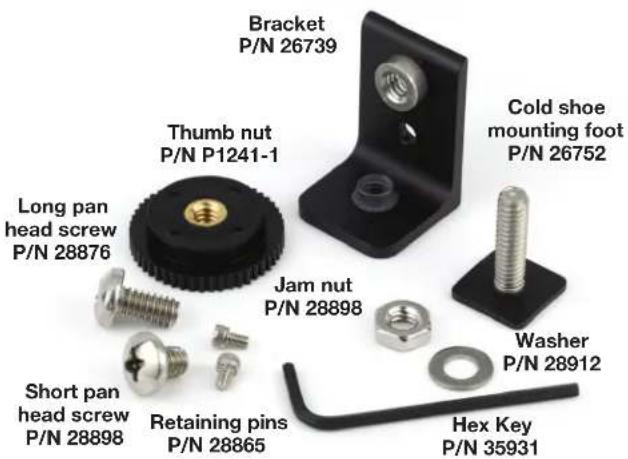
For a vertical mounting, attach the right angle bracket to the bottom of the sleeve.
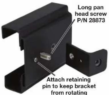
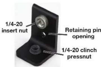
The bracket provides two different mounting nuts. The standard pressnut is used to attach the sleeve. The tensioning (clinch type) pressnut is used to attach the cold shoe mounting foot.
Attach the bracket to the sleeve with the long pan head screw into the standard pressnut. The retaining pin fits into the opening in the bracket. Attach the cold shoe mounting foot to the tensioning nut and rotate it to orient the receiver as desired.
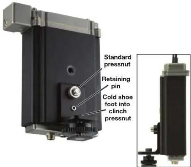
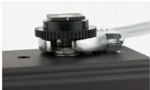
The clinch nuts in the foot and housing apply friction to the threads to allow the foot to be rotated to the desired position, with the jam nut locking it in place. Use a wrench to rotate the foot, then tighten the jam nut to prevent the foot from rotating.
Clinch pressnut in bracket and sleeve

For horizontal mounting, insert the cold shoe foot into the clinch nut in the sleeve. Rotate the foot to the desired position, then tighten the jam nut to lock it in place.
natural_image
Close-up of a mechanical gear assembly with a transparent cable inserted (no visible text or symbols)Tighten the jam nut to prevent the foot from rotating
Used together, the battery sled, sleeve and mounting foot create a versatile, stand-alone, self-powered configuration for an SR Series or DSR receiver.
Troubleshooting
Symptom
Possible
Cause
INITIAL POWER ON
Display not active or lit. External power supply disconnected or inadequate.
Main power supply fuse tripped. Turn the receiver off, remove the cause of the overload and turn the receiver back on.
Wrong polarity power source. The external DC in requires POSITIVE to be on the center pin.
ANTENNAS AND RF SIGNAL STRENGTH
RF Level is weak. Receiver may need to be moved or reoriented.
Antenna on transmitter may be defective or poorly connected - double check antenna on transmitter.
Improper length of antenna, or wrong antenna on transmitter or receiver. UHF whip antennas are generally about 3 to 5 inches long. UHF helical antennas may be shorter, but are often less efficient.
No RF Signal Make certain frequency settings on transmitter match the receiver frequency settings.
Ensure transmitter is in transmit mode.
AUDIO SIGNAL QUALITY
Poor signal to noise ratio Transmitter gain set too low.
The noise may not be in the wireless system. Turn the transmitter audio gain all the way down and see if the noise remains. If the noise remains, then turn the power off at the transmitter and see if it remains. If the noise is still present, then the problem is not in the transmitter.
If noise is still present when the transmitter is turned off, try lowering the audio output level on the DSR and see if the noise lowers correspondingly. If the noise remains, the problem is not in the receiver.
Receiver output is too low for the input of the device it is feeding. Try increasing the output level of the DSR.
Distortion Transmitter input gain too high. Check and/or readjust input gain on transmitter according to the LEDs on the transmitter and then verify the setting with the audio meter in the main window.
Audio output level too high for the device the DSR Lower the output level of the DSR.
is feeding.
Bad frequency response or generally poor audio quality.
the transmitter in use.
Ensure the receiver is set to the compatibility mode that matches
DISPLAY NOT ACTIVE OR LIT Ensure that the unit has the correct power supply and is connected.
Display has timed out. Press any button to revive.
Specifications and Features
Operating Frequencies (MHz):
Model A1B1: 470.100 - 614.375
Model B1C1: 537.600 - 691.175
941: 941.525 - 959.825
961: 961.100 - 1014.900
NOTE: It's the user's responsibility to select the approved frequencies for the region where the transmitter is operating.
Frequency Selection Steps: 25 kHz
Frequency Stability: ±0.001%
Front end bandwidth: ±5.5 MHz, @ -3 dB
Sensitivity: 20 dB Sinad: 0.9 uV(-108 dBm), A weighted
60 dB Quieting: 1.12 uV (-105 dBm), A weighted
AM rejection: >60 dB, 2 uV to 1 Volt
Modulation acceptance: 85 kHz
Spurious rejection: 85 dB
Third order intercept: +15 dBm
Diversity method: Vector diversity
Antenna inputs: 50 Ohm; SMA female connectors
Audio output connectors: • Interchangeable D connector adapters for camera slot interfaces
- Dual TA3 male (mini XLR) balanced output adapter
- Battery sled adapters with TA3 male outputs.
Audio Performance (overall system):
Frequency Response: 25 Hz to 20 kHz (+0/-3 dB)
THD: 0.2% (typical)
SNR at receiver output (dB):
| SmartNR | No Limiting | w/Limiting | |
| Note: The dual envelope “soft” limiter provides exceptionally good handling of transients using variable attack and release time constants. Once activated, | OFF | 103.5 | 108.0 |
| NORMAL | 107.0 | 111.5 | |
| FULL | 108.5 | 113.0 |
the limiter compresses 30+ dB of transmitter input range into 4.5 dB of receiver output range, thus reducing the measured figure for SNR without limiting by 4.5 dB.
Input Dynamic Range: 125 dB (with full Tx limiting)
Overall Latency (time delay): 1.4 ms with digital source, <2.9 sm with Hybrid TX
Audio Test Tone: 1 KHz, -50 to +7 dBu, <1%THD
Controls:
Front Panel: • Color LCD display
- Menu/Sel, Pwr/Back, Up/Down Arrow Buttons
- USB Port
• IR Port
Rear Panel:
accessory panels.
• Proprietary connector for audio/power
External Power:
3.25 W; Max 400 mA at 7 VDC
Minimum 7 Volts to maximum 18 VDC
Weight: 408 grams (14.4 oz.) w/o audio adapter
Dimensions: 3.375" wide x 1.23" high x 4.50" deep
85.7 wide x 31 high x 114 deep mm
Specifications subject to change without notice.
FCC Notice
NOTE: This equipment has been tested and found to comply with the limits for a Class B digital device, pursuant to part 15 of the FCC Rules. These limits are designed to provide reasonable protection against harmful interference in a residential installation. This equipment generates, uses and can radiate radio frequency energy and, if not installed and used in accordance with the instructions, may cause harmful interference to radio communications. However, there is no guarantee that interference will not occur in a particular installation. If this equipment does cause harmful interference to radio or television reception, which can be determined by turning the equipment off and on, the user is encouraged to try to correct the interference by one or more of the following measures:
- Reorient or relocate the receiving antenna.
- Increase the separation between the equipment and receiver.
- Connect the equipment into an outlet on a circuit different from that to which the receiver is connected.
- Consult the dealer or an experienced radio/TV technician for help.
Changes or modifications to this equipment not expressly approved by Lectrosonics, Inc. could void the user's authority to operate it.
Service and Repair
If your system malfunctions, you should attempt to correct or isolate the trouble before concluding that the equipment needs repair. Make sure you have followed the setup procedure and operating instructions. Check the interconnecting cables and then go through the Troubleshooting section in this manual.
We strongly recommend that you do not try to repair the equipment yourself and do not have the local repair shop attempt anything other than the simplest repair. If the repair is more complicated than a broken wire or loose connection, send the unit to the factory for repair and service. Don't attempt to adjust any controls inside the units. Once set at the factory, the various controls and trimmers do not drift with age or vibration and never require readjustment. There are no adjustments inside that will make a malfunctioning unit start working.
LECTROSONICS' Service Department is equipped and staffed to quickly repair your equipment. In warranty repairs are made at no charge in accordance with the terms of the warranty. Out-of-warranty repairs are charged at a modest flat rate plus parts and shipping. Since it takes almost as much time and effort to determine what is wrong as it does to make the repair, there is a charge for an exact quotation. We will be happy to quote approximate charges by phone for out-of-warranty repairs.
Returning Units for Repair
For timely service, please follow the steps below:
A. DO NOT return equipment to the factory for repair without first contacting us by email or by phone. We need to know the nature of the problem, the model number and the serial number of the equipment. We also need a phone number where you can be reached 8 A.M. to 4 P.M. (U.S. Mountain Standard Time).
B. After receiving your request, we will issue you a return authorization number (R.A.). This number will help speed your repair through our receiving and repair departments. The return authorization number must be clearly shown on the outside of the shipping container.
C. Pack the equipment carefully and ship to us, shipping costs prepaid. If necessary, we can provide you with the proper packing materials. UPS is usually the best way to ship the units. Heavy units should be "double-boxed" for safe transport.
D. We also strongly recommend that you insure the equipment, since we cannot be responsible for loss of or damage to equipment that you ship. Of course, we insure the equipment when we ship it back to you.
Lectrosonics USA:
Mailing address: Shipping address: Telephone:
Lectrosonics, Inc. Lectrosonics, Inc. (505) 892-4501
PO Box 15900 561 Laser Rd. NE, Suite 102 (800) 821-1121 Toll-free
Rio Rancho, NM 87174 Rio Rancho, NM 87124 (505) 892-6243 Fax
USA USA
Web:
E-mail:
www.lectrosonics.com sales@lectrosonics.com
service.repair@lectrosonics.com
Lectrosonics Canada:
Mailing
Address:
Telephone:
E-mail:
720 Spadina Avenue,
(416) 596-2202
Sales:
colinb@lectrosonics.com
Suite 600 (877) 753-2876 Toll-free Service: joeb@lectrosonics.com
Toronto, Ontario M5S 2T9
(877-7LECTRO)
(416)
596-6648
Fax
Self-Help Options for Non-Urgent Concerns
Our Facebook groups and weblists are a wealth of knowledge for user questions and information. Refer to:
Lectrosonics General Facebook Group: https://www.facebook.com/groups/69511015699
D Squared, Venue 2 and Wireless Designer Group: https://www.facebook.com/groups/104052953321109
The Wire Lists: https://lectrosonics.com/the-wire-lists.html
LIMITED ONE YEAR WARRANTY
The equipment is warranted for one year from date of purchase against defects in materials or workmanship provided it was purchased from an authorized dealer. This warranty does not cover equipment which has been abused or damaged by careless handling or shipping. This warranty does not apply to used or demonstrator equipment.
Should any defect develop, Lectrosonics, Inc. will, at our option, repair or replace any defective parts without charge for either parts or labor. If Lectrosonics, Inc. cannot correct the defect in your equipment, it will be replaced at no charge with a similar new item. Lectrosonics, Inc. will pay for the cost of returning your equipment to you.
This warranty applies only to items returned to Lectrosonics, Inc. or an authorized dealer, shipping costs prepaid, within one year from the date of purchase.
This Limited Warranty is governed by the laws of the State of New Mexico. It states the entire liability of Lectrosonics Inc. and the entire remedy of the purchaser for any breach of warranty as outlined above. NEITHER LECTROSONICS, INC. NOR ANYONE INVOLVED IN THE PRODUCTION OR DELIVERY OF THE EQUIPMENT SHALL BE LIABLE FOR ANY INDIRECT, SPECIAL, PUNITIVE, CONSEQUENTIAL, OR INCIDENTAL DAMAGES ARISING OUT OF THE USE OR INABILITY TO USE THIS EQUIPMENT EVEN IF LECTROSONICS, INC. HAS BEEN ADVISED OF THE POSSIBILITY OF SUCH DAMAGES. IN NO EVENT SHALL THE LIABILITY OF LECTROSONICS, INC. EXCEED THE PURCHASE PRICE OF ANY DEFECTIVE EQUIPMENT.
This warranty gives you specific legal rights. You may have additional legal rights which vary from state to state.


- Two Channel Digital Slot Receiver
- DSR-A1B1, DSR-B1C1, DSR-941, DSR-961
- CE UK CA
- Quick Start Summary
- Table of Contents
- DSR Block Diagram
- Technical Description
- Compatibility Modes
- Encryption
- Vector Diversity
- RF Frequency Tracking Front-End
- Smart Noise Reduction (SmartNR™)
- Audio Output Level
- Test Tone
- Power Supply
- Color LCD Display
- Power Off
- DSR Front Panel Controls
- MENU/SEL Button
- PWR/BACK Button
- Up/Down Arrow Buttons
- Antenna Port (2)
- IR (infrared) Port
- Menu Item Descriptions
- RF Setup
- Finding Clear Frequencies with SmartTune:
- Frequency:
- Tuning Groups:
- Scan:
- Scan Zoom:
- Clear Scan Data:
- Group Edit:
- Editing Existing Entries:
- Diversity:
- Using Diversity Modes
- Frequency Diversity
- Pilot Bypass:
- TxInfo:
- Audio Setup
- Audio Level:
- Output Type:
- Routing:
- Smart NR:
- Talkback:
- Polarity:
- Compat Modes
- IR & Keys Menu
- DSR LCD Menu Map
- Send Frequency
- Send All
- (available only for digital compat modes)
- Get Frequency
- Get All
- Group Sync
- Encryption Key Management
- Encryption Keys
- Send Key
- Settings Menu
- Lock/Unlock
- Backlight
- Rx On/Off
- TxBat Type
- TxBatt Timer
- TxBatt Icon
- AutoOn
- Edit Names
- Locale
- Default
- About
- Antenna Mounting and Orientation
- AMJ Jointed Antenna
- SNA600A Omni Dipole Antenna
- Antenna/Block Reference Table
- Interference Management Multi-channel System Checkout
- Set up the system for testing.
- Set all receivers on clear channels.
- Turn each transmitter on one at a time.
- Turn each transmitter off one at a time.
- Firmware Update Instructions
- Supplied Parts and Accessories
- AMJ19
- AMJ22
- AMJ25
- AMJ944
- AMJ961
- Optional Parts and Accessories
- 21770
- 21926
- ACOAXTX
- DSREXTUSB Adapter
- PS200A
- PS2200A
- SREXT
- SRSNY
- SRSUPER
- SRBATTSLED TOP
- SRBATTSLED BOTTOM
- SRHARNESS
- SRUNISCREWKIT
- UMCWBD-L
- ZS-UMC-DSR4-DSR-KIT
- ZS-UMC-DSR4-HIROSE4-KIT
- Audio Output Cables and Connectors
- MCSR/5PXLR5P
- MCSR/5PXLR2
- MCSRPT
- MCSRXLR
- MCSRTRS
- MCTA5TA3F2
- MCTA5TPT2
- RATPAC Adapter Kit
- External Power Supplies
- DCR15/4AU
- DCR15/1A8U-H
- External Power Cables
- 21425
- 21472
- 21586
- Camera Slot Adapters
- Installing Camera Slot Adapters
- IMPORTANT WARNING
- Rear Panel and Adapters
- Installing Rear Panel Adapters
- Adapters for Stand-Alone Use
- Battery Adapters and Mounting Kits
- Installing the SRBATTSLED
- Battery Life
- SRSLEEVE mounting adapter
- Troubleshooting
- INITIAL POWER ON
- ANTENNAS AND RF SIGNAL STRENGTH
- AUDIO SIGNAL QUALITY
- Specifications and Features
- FCC Notice
- Service and Repair
- Returning Units for Repair
- Lectrosonics USA:
- Web:
- E-mail:
- Lectrosonics Canada:
- Mailing
- Address:
- Telephone:
- Self-Help Options for Non-Urgent Concerns
- LIMITED ONE YEAR WARRANTY
Brand : Lectrosonics
Model : DSR-941
Category : Audio transceiver