
DPR-A - Audio transceiver Lectrosonics - Free user manual and instructions
Find the device manual for free DPR-A Lectrosonics in PDF.

| Product Type | Digital Plug-On Audio Transceiver with Recorder |
| Brand | Lectrosonics |
| Model | DPR-A |
| Frequency Range (US) | 470.100 - 607.950 MHz |
| Frequency Selection Steps | 25 kHz |
| RF Output Power | Selectable 25 or 50 mW |
| Modulation | 8PSK |
| Input Connector | 3-pin XLR (female) |
| Phantom Power | 5V, 15V, 48V selectable |
| Input Impedance | 1 kΩ |
| Input Limiter | Dual envelope, >30 dB range |
| Gain Control Range | 55 dB in 1 dB steps |
| Audio Frequency Response | 25 Hz - 20 kHz (±0.5/-1.5 dB) |
| Dynamic Range | 125 dB (with full limiting) |
| Encryption | AES 256-CTR |
| Recorder Storage | microSDHC (up to 32 GB) |
| Recorder Format | 24-bit / 48 kHz .wav (BWF) |
| Power Source | 2 x AA batteries (lithium recommended) |
| Housing Material | Machined aluminum with corrosion-resistant finish |
| Control Panel | LCD, membrane switches, multicolor LEDs |
| Antenna Connector | SMA jack |
| Infrared Port | For setup synchronization |
| Accessories Included | Whip antenna (AMM series), microSDHC adapter |
| Maintenance | Wipe with dry cloth; avoid solvents |
| Service | Factory repair available; contact Lectrosonics |
Frequently Asked Questions - DPR-A Lectrosonics
User questions about DPR-A Lectrosonics
0 question about this device. Answer the ones you know or ask your own.
Ask a new question about this device
Download the instructions for your Audio transceiver in PDF format for free! Find your manual DPR-A - Lectrosonics and take your electronic device back in hand. On this page are published all the documents necessary for the use of your device. DPR-A by Lectrosonics.
USER MANUAL DPR-A Lectrosonics
natural_image
Close-up of a black electronic device with control panel and indicator lights (no readable text or symbols)DPR-A
Table of Contents
General Technical Description 4
Low Frequency Roll-Off 4 Input Limiter 4
Input Limiter ....4 Control Panel ....4
Alternate Recording Function 4
Alternate Recording Function 4 Encryption 4
Features......5
LCD Screen 5
Power LED 5
Key LED 5
Modulation LEDs....5
MENU/SEL Button 5
BACK Button 5
UP/DOWN Arrow Buttons 5
Menu Shortcuts....5
Audio Input Jack....5
Antenna....5 ID (infrared) Part 5
IR (Infrared) Port 5
Battery Installation .... 6 Attaching/Removing a Microphone .... 6
Attaching/Removing a Microphone 6
Operating Instructions....7 Powering On in Operating Mode....7
Powering On in Operating Mode....7 Powering On in Standby Mode....7
Powering On In Standby Mode .... 7
Powering Off 7 Transmitter Operating Instructions 7
Transmitter Operating Instructions ....
Recorder Operating Instructions 8 Formatting CD Card
Formatting SD Card....8 IMPORTANT
IMPORTANT 9 XML HEADER SUPPORT 9
IAMETLEADER SUPPORT .... 9 Compatibility with microSPHC memory cards .... 0
Compatibility with microSDHC memory cards ....9
DPR Menu....10 Setup Screen Details....11
Setup Screen Details ....12 Main Window Indicators 1
Main Window Indicators Turning Control Panel LEDs ON/OFF
Turning Control Panel LEDs ON/OFF ...... Helpful Features on Receivers ...... 1
Helpful Features on Receivers....12 Input Many:
Input Menu .... 1 Adjusting the Input Gain . 1
Adjusting the Input Gain....12 Selecting the Low Frequency Roll off....1
Selecting the Low Frequency Roll-on ....
Selecting Audio Polarity (Phase)....13
Selecting Phantom Power Supply....1:
Xmit Menu 1
Selecting Frequency 1
SDCard Menu 14
Record or Stop 14
Choosing Files for Replay 14
Choosing Takes for Replay 14
Setting Scene and Take Number 14
Formatting microSDHC Memory Card....14
Recorded File Naming 14
microSDHC Memory Card Info 15
Load Frequency Group 15
Save Frequency Group 15
TCode Menu 15
TC Jam (jam timecode)....15
Setting Frame Rate....15
Use Clock....15
Key Menu....16
KeyType 16
SendKey....16
Setup Menu 16
Setting Auto On....16
Enabling Remote Function....16
Setting Battery Type 16
Setting Battery Timer 17
Setting Date and Time (Clock) 17
Locking/Unlocking Settings....17
Backlit Settings 17
Turn LEDs On/Off 17
Restoring Default Settings 17
About 17
LectroRM....18
Accessories 19
21750 Barrel Adapter....19
MCA-M30 Barrel Adapter....19
PHTRAN3 19
MCA5X....19
MCA-TPOWER 19
Specifications and Features....20
Transmitter 20
Firmware Update 21
Recovery Process 22
Service and Repair 23
Returning Units for Repair 23
DPR-A
General Technical Description
The Lectrosonics DPR-A digital plug-On transmitter benefits from a fourth generation design with specially developed, high efficiency digital circuitry for extended operating time on two AA batteries. The unique design provides several distinct features for professional applications:
• Outstanding UHF operating range
- Superb audio quality
- On board recording
• Corrosion-resistant housing
The transmitter uses a standard 3-pin XLR input jack for use with any microphone with a mating XLR connector. An LCD, membrane switches and multi-color LEDs on the control panel make input gain adjustments and frequency selection quick and accurate, without having to view the receiver. The housing is machined from a solid aluminum block to provide a lightweight and rugged package. A special non-corrosive finish resists salt water exposure and perspiration in extreme environments.
The DSP controlled input limiter features a wide range dual envelope design which cleanly limits input signal peaks over 30 dB above full modulation. Switching power supplies provide constant voltages to the transmitter circuits from the beginning (3 Volts) to the end (1.7 Volts) of battery life, and an ultra low noise input amplifier for quiet operation.
The DPR-A has an external SMA antenna jack, which accepts Lectrosonics steel flex wire AMM or AMJ series antennas.
Low Frequency Roll-Off
The low frequency roll-off can be set for a 3 dB down
Input Limiter
A DSP-controlled analog audio limiter is employed before the analog-to-digital (A-D) converter. The limiter has a range of more than 30 dB for excellent overload protection. A dual release envelope makes the limiter acoustically transparent while maintaining low distortion. It can be thought of as two limiters in series, a fast attack and release limiter followed by a slow attack and release limiter. The limiter recovers quickly from brief transients, with no audible side effects, and also recovers slowly from sustained high levels, to keep audio distortion low and while preserving short term dynamics.
Control Panel
The control panel includes five membrane switches and an LCD screen to adjust the operational settings. Multicolor LEDs are used to indicate audio signal levels for accurate gain adjustment, battery status and encryption key function.
Alternate Recording Function
The DPR has a built in recording function for use in situations where RF may not be possible or to work as a stand alone recorder. The record function and transmit functions are exclusive of each other - you cannot record AND transmit at the same time. When the unit is transmitting and recording is turned on, the audio in the RF transmission will stop, but the battery status will still be sent to the receiver.
The recorder samples at 48 kHz rate with a 24 bit sample depth. The micro SDHC card also offers easy firmware update capabilities without the need for a USB cable or driver issues.
Encryption
When transmitting audio, there are situations where privacy is essential, such as during professional sport-
Features

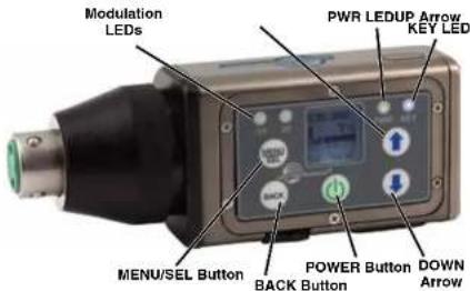
LCD Screen
The LCD is a numeric-type Liquid Crystal Display with several screens that allow settings to be made with the MENU/SEL and BACK buttons, and the UP and DOWN arrow buttons to configure the transmitter. The transmitter can be turned on in a "standby" mode with the carrier turned off to make adjustments without the risk of interfering with other wireless systems nearby.
Power LED
The PWR LED glows green when the batteries are charged. The color changes to red when there is about 20 minutes of life left. When the LED begins to blink red, there are only a few minutes of life.
A weak battery will sometimes cause the PWR LED to glow green immediately after being put into the unit, but will soon discharge to the point where the LED will go red or shut off completely.
Key LED
The blue key LED will blink if an encryption key is not
MENU/SEL Button
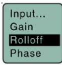
The MENU/SEL button is used to display the transmitter menu items. Press once to open the menu, then use the UP and DOWN arrows to scroll menu items. Press MENU/SEL again to choose an option from the menu.
BACK Button
Once a selection is made in a menu, press the BACK Button to save your selection and go back to the previous menu.
UP/DOWN Arrow Buttons
The UP and DOWN arrow buttons are used to scroll through menu options.
From the Main Screen, use the UP Arrow to turn the LEDs on and the DOWN Arrow to turn the LEDs off.
Menu Shortcuts
From the main/home screen, the following menu short-cuts are available:
Simultaneous press of BACK button + UP arrow button: Begin record
Simultaneous press of BACK button + DOWN arrow button: Stop record
Press MENU/SEL: Shortcut to adjust input gain menu
Press the UP arrow button to turn the control panel LEDs on; press the DOWN arrow button to turn them off
Audio Input Jack
The 3 pin female XLR to AES standard balanced Input jack on the transmitter accommodates hand-held, shotgun and measurement microphones. Phantom power can be set at various levels for use with a wide variety of electret microphones.
DPR-A
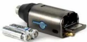
Battery Installation
The battery compartment door is made of machined aluminum and is hinged to the housing to prevent it being damaged or lost.
The transmitter is powered by two AA batteries.
Note: Standard zinc-carbon batteries marked "heavy-duty" or "long-lasting" are not adequate.
natural_image
Exterior view of a modern office building (no signage)To install new batteries:
- Slide open the Battery Cover and remove any old batteries.
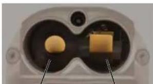
- Insert the new batteries into the housing. One battery goes in positive (+) end first, the other negative (-) end first. Look into the battery compartment to determine which end goes in which side. The side with the circular insulator is the side which accepts the positive end of the battery.
natural_image
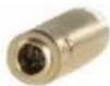
Close-up of a device's internal components, possibly a lens or connector, with no visible text or symbols.Attaching/Removing a Microphone
The spring loaded coupler under the XLR jack maintains a secure fit to the microphone jack with continuous pressure applied by an internal spring.
To attach the microphone, simply align the XLR pins and press the microphone onto the transmitter until the coupler retracts and latches. A click sound will be heard as the connector latches.
To remove the microphone, hold the transmitter body in one hand with the microphone pointing upward. Use your other hand to rotate the coupler until the latch releases and the coupler rises slightly.
Do not pull on the microphone while releasing the locking collar.
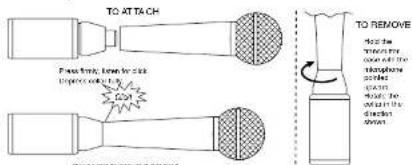
NOTE: Do not hold or apply any pressure to the microphone body while trying to remove it, as this may prevent the latch from releasing.
Operating Instructions
Turning Power ON
Powering On in Operating Mode
Press and hold the POWER Button briefly until the progress bar on the LCD finishes.
When you release the button, the unit will be operational with the RF output turned on and the Main Window displayed.
RF Indicator not blinking
Hold power button until the progress bar finishes

Powering On in Standby Mode
RF Indicator blinks
A brief press of the POWER
Transmitter Operating Instructions
- Install battery(s)
- Turn power on in the Standby mode (see previous section)
- Connect microphone and place it in the position where it will be used.
- Have the user talk or sing at the same level that will be used in the production, and adjust the input gain so that the -20 LED blinks red on louder peaks.

Use the UP and DOWN arrow buttons to adjust the gain until the -20 LED blinks red on louder peaks
| Signal Level -20 LED | -10 LED | |
| Less than -20 dB | ● Off Off | ● |
| -20 dB to -10 dB | ● Green Off | ● |
| -10 dB to +0 dB | ● Green Green | |
| +0 dB to +10 dB | ● Red Green | |
| Greater than +10 dB | ● Red Red | ● |
- Set the frequency to match the receiver.
- Set encryption key type and sync with receiver.
- Turn the power off and then back on while holding the POWER button in and waiting until the progress bar finishes.
DPR-A
Recorder Operating Instructions
• Install battery(s)
- Insert microSDHC memory card
- Turn power on
- Format memory card
- Connect microphone and place it in the position where it will be used.
- Have the user talk or sing at the same level that will be used in the production, and adjust the input gain so that the -20 LED blinks red on louder peaks.
Use the UP and DOWN arrow buttons to adjust the gain until the -20 LED blinks red on louder peaks
| Signal Level -20 LED -10 LED | ||
| Less than -20 dB | ● Off Off | ● |
| -20 dB to -10 dB | ● Green Off | ● |
| -10 dB to +0 dB | ● Green Green | |
| +0 dB to +10 dB | ● Red Green | ● |
| Greater than +10 dB | ● Red Red | ● |
- Press MENU/SEL, choose SDCard and Record from the menu


Formatting SD Card
New microSDHC memory cards come pre-formatted with a FAT32 file system which is optimized for good performance. The DPR relies on this performance and will never disturb the underlying low level formatting of the SD card. When the DPR "formats" a card, it performs a function similar to the Windows "Quick Format" which deletes all files and prepares the card for recording. The card can be read by any standard computer but if any write, edit or deletions are made to the card by the computer, the card must be re-formatted with the DPR to prepare it again for recording. The DPR never low level formats a card and we strongly advise against doing so with the computer.
To format the card with the DPR, select Format Card in the menu and press MENU/SEL on the keypad.
NOTE: An error message will appear if samples are lost due to a poor performing "slow" card.
WARNING: Do not perform a low level format (complete format) with a computer. Doing so may render the memory card unusable with the DPR recorder.
With a windows based computer, be sure to check the quick format key before formatting the cord.
IMPORTANT
The formatting of the SD card sets up contiguous sectors for maximum efficiency in the recording process. The file format utilizes the BEXT (Broadcast Extension) wave format which has sufficient data space in the header for the file information and the time code imprint.
The SD card, as formatted by the DPR recorder, can be corrupted by any attempt to directly edit, change, format or view the files on a computer.
The simplest way to prevent data corruption is to copy the .wav files from the card to a computer or other Windows or OS formatted media FIRST. Repeat - COPY THE FILES FIRST!
Do not rename files directly on the SD card.
Do not attempt to edit the files directly on the SD card.
Do not save ANYTHING to the SD card with a computer (such as the take log, note files etc) - it is formatted for DPR recorder use only.
Do not open the files on the SD card with any third party program such as Wave Agent or Audacity and permit a save. In Wave Agent, do not IMPORT - you can OPEN and play it but do not save or Import - Wave Agent will corrupt the file.
In short - there should be NO manipulation of the data on the card or addition of data to the card with anything other than an DPR recorder. Copy the files to a computer, thumb drive, hard drive, etc. that has been formatted as a regular OS device FIRST - then you can edit freely.
iXML HEADER SUPPORT
Recordings contain industry standard iXML chunks in the file headers, with the most commonly used fields filled in.
Compatibility with microSDHC memory cards
Please note that the DPR is designed for use with microSDHC memory cards. There are several types of SD card standards (as of this writing) based on capacity (storage in GB).
SDSC: standard capacity, up to and including 2 GB – DO NOT USE!
SDHC: high capacity, more than 2 GB and up to and including 32 GB – USE THIS TYPE.
SDXC: extended capacity, more than 32 GB and up to and including 2 TB – DO NOT USE!
SDUC: extended capacity, more than 2TB and up to and including 128 TB – DO NOT USE!
The larger XC and UC cards use a different formatting method and bus structure and are NOT compatible with the recorder. These are typically used with later generation video systems and cameras for image applications (video and high resolution, high speed photography).
ONLY microSDHC memory cards should be used. They are available in capacities from 4GB to 32GB. Look for the Speed Class 10 cards (as indicated by a C wrapped around the number 10), or the UHS Speed Class I cards (as indicated by the numeral 1 inside a U symbol). Also note the microSDHC Logo.
If you are switching to a new brand or source of card, we always suggest testing first before using the card on a critical application.
The following markings will appear on compatible memory cards. One or all of the markings will appear on the card housing and the packaging.

SanDisk Ultra
DPR-A
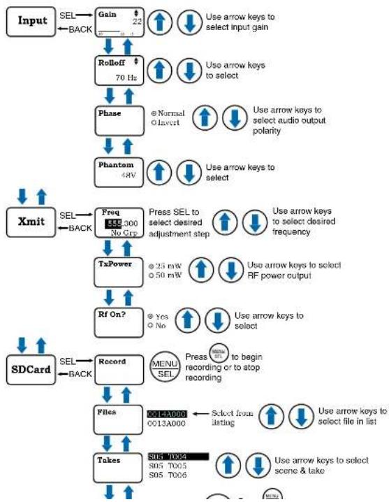
DPR Menu
flowchart
graph TD
    A["Input"] --> B["SEL"]
    B --> C["Gain 22"]
    C --> D["ROLloff 70 Hz"]
    D --> E["Phase"]
    E --> F["Phantom 4W"]
    F --> G["Xmit"]
    G --> H["SEL"]
    H --> I["Freq 355/300 No Grp"]
    I --> J["TxPower"]
    J --> K["Rf On?"]
    K --> L["Record"]
    L --> M["Files"]
    M --> N["Takes"]
    N --> O["SOL T004 S05 T005 S05 T006"]
    O --> P["SDCard"]
    P --> Q["SEL"]
    Q --> R["Back"]
    R --> S["Use arrow keys to select input gain"]
    S --> T["Use arrow keys to select"]
    T --> U["Use arrow keys to select audio output polarity"]
    U --> V["Use arrow keys to select"]
    V --> W["Use arrow keys to select desired frequency"]
    W --> X["Use arrow keys to select RF power output"]
    X --> Y["Use arrow keys to select"]
    Y --> Z["Press SEL to select desired adjustment step"]
    Z --> AA["Use arrow keys to select desired frequency"]
    AA --> AB["Use arrow keys to select RF power output"]
    AB --> AC["Use arrow keys to select"]
    AC --> AD["Press menu recording or to atop recording"]
    AD --> AE["Select from listing"]
    AE --> AF["Use arrow keys to select file in list"]
    AF --> AG["Use arrow keys to select scene & take"]
Digital Plug-On Transmitter
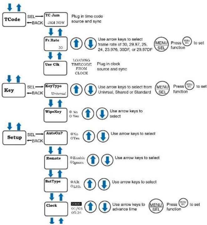
flowchart
graph TD
    A["TCode"] -->|SEL| B["TC Jam"]
    B -->|BACK| C["TC Jam JAM NOW"]
    C --> D["Fr.Rate 30"]
    D --> E["Use Clk"]
    E --> F["LOADING TIMECODE FROM CLOCK"]
    F --> G["Key Type Universal"]
    G --> H["WipeKey"]
    H --> I["Setup"]
    I -->|SEL| J["AutoOn?"]
    J --> K["Remote"]
    K --> L["BatType"]
    L --> M["Clock"]
    M --> N["21000 07/03 06:24"]
    style A fill:#f9f,stroke:#333
    style N fill:#bbf,stroke:#333
DPR-A
Setup Screen Details
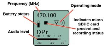
Main Window Indicators
The Main Window displays the operating frequency, Standby or Operating mode, battery status, if an SDHC card is presnt/recording, and audio level.
Turning Control Panel LEDs ON/OFF
From the main menu screen, a quick press of the UP arrow button turns the control panel LEDs on. A quick press of the DOWN arrow button turns them off. The buttons will be disabled if the LOCKED option is selected in the Setup menu.
The control panel LEDs can also be turned on and off with the LED Off option in the Setup menu.
Helpful Features on Receivers
To aid in finding clear frequencies, several Lectrosonics receivers offer a SmartTune feature that scans the tuning range of the receiver and displays a graphical report that shows where RF signals are present at different levels, and areas where there is little or no RF energy present. The software then automatically selects the best channel for operation.
Lectrosonics receivers equipped with an IR Sync function allow the receiver to set frequency on the transmitter via an infrared link between the two units.
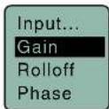
Input Menu
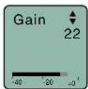
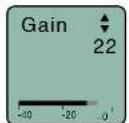
Adjusting the Input Gain
The two bicolor Modulation LEDs on the control panel provide a visual indication of the audio signal level entering the transmitter. The LEDs will glow either red or green to indicate modulation levels as shown in the following table.
| Signal Level -20 LED | -10 LED | |
| Less than -20 dB | ● Off Off | ● |
| -20 dB to -10 dB | ● Green Off | ● |
| -10 dB to +0 dB | ● Green Green | |
| +0 dB to +10 dB | ● Red Green | ● |
| Greater than +10 dB | ● Red Red | ● |
NOTE: Full modulation is achieved at 0 dB, when the "-20" LED first turns red. The limiter can cleanly handle peaks up to 30 dB above this point.
It is best to go through the following procedure with the transmitter in the standby mode so that no audio will enter the sound system or recorder during adjustment.
1) With fresh batteries in the transmitter, power the unit on in the standby mode (see previous section Turning Power ON and OFF).
2) Navigate to the Gain setup screen.


3) Prepare the signal source. Position a microphone
Selecting the Low Frequency Roll-off
It is possible that the low frequency roll-off point could affect the gain setting, so it's generally good practice to make this adjustment before adjusting the input gain. The point at which the roll-off takes place can be set to:
- 25 Hz • 100 Hz
• 35 Hz • 120 Hz - 50 Hz • 150 Hz
- 70 Hz
The roll-off is often adjusted by ear while monitoring the audio.

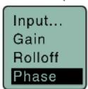
Selecting Audio Polarity (Phase)
Audio polarity can be inverted at the transmitter so the audio can be mixed with other microphones without comb filtering. The polarity can also be inverted at the receiver outputs.

Selecting Phantom Power Supply
About the Phantom Power Supply
Three phantom voltages are selectable from the control panel. The voltages are:
• 5 Volts for lavallere microphones,
- 15 Volts for some professional mics requiring high current and for many common stage mics that will operate over a wide phantom Voltage range of 12 to 48 Volts. With the proper adapter, this position can also be used with T power microphones. See our web site for details on finding or making the proper adapter.
- 48 Volts for microphones that do in fact require a supply greater than 18 Volts. (See below for a discussion of why 42 and not a "true" 48 Volts.)
For longest battery life use the minimum phantom voltage necessary for the microphone. Many stage microphones regulate the 48 Volts down to 10 Volts internally anyway, so you might as well use the 15 Volt setting and save some battery power. If you are not using a microphone for the input device, or are using a microphone that does not require phantom power, turn the phantom power off.
Phantom power should only be used with a fully floating, balanced device, such as common microphones with a 3-pin XLR connector. If you use the phantom power with an unbalanced device or if pins 2 or 3 are DC connected to ground, then you will draw maximum current from the power supply. The DPR is fully protected against such shorts but the batteries will be drained at twice the normal rate.
The transmitter can supply 4mA at 42 Volts, 8mA at 15 Volts, and 8mA at 5 Volts. The 42 Volts setting actually supplies the same voltage to a 48 Volt microphone as the DIN standard arrangement due to a dynamic biasing scheme that does not have as much voltage drop as the DIN standard. The 48 Volt DIN standard arrangement protects against shorts and high fault current with high resistance in the power supply feeds
DPR-A
Xmit Menu
Selecting Frequency
The setup screen for frequency selection offers two ways to browse the available frequencies.
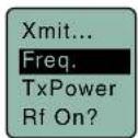

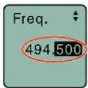
Press the MENU/SEL button to select each field. Use the ① and Arrow buttons to adjust the frequency. Each field will step through the available frequencies in a different increment.
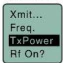
Setting Transmitter Output Power
The output power can be set to 25 mW or 50 mW.

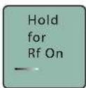
Turning Rf Output On
It's best to set frequency and other settings in the standby mode (Rf off) so that no audio will enter the sound system or recorder during adjustment. Use this menu item to turn the Rf carrier on and off.

Rf On?
Choosing Files for Replay

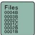
Select recorded files on microSDHC memory card.
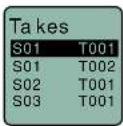
Choosing Takes for Replay
Use UP and DOWN arrows to toggle and MENU/SEL to play back.

Setting Scene and Take Number
Use UP and DOWN arrows to advance Scene and Take and MENU/SEL to toggle. Press the BACK button to return to menu.

Formatting microSDHC Memory Card
Formats the microSDHC memory card.
WARNING: This function erases any content on the microSDHC memory card.
microSDHC Memory Card Info
Information regarding the microSDHC memory card including space remaining on card.
![SDCard... SD Info LoadGrp SaveGrp [DPR] E..... 0/ 14G. Max Rec 29:52:52 Fuel gauge Storage used Storage capacity Available recording time (H : M : S)](/content/2026/06/1216266/images/6cf6ad7d1da0370d7ec1361e7c7a851b8f7b97f786132dfec1ba0c4f5d085c8d.jpg)
Load Frequency Group
The frequency groups feature allows groups of frequencies to be created, stored and used to constrain tuning. The groups are created using Lectrosonics DSQD receiver or via Wireless Designer, then the groups are shared with the DPR via IR sync or microSDHC Memory Card transmission.
Use UP and DOWN arrows to toggle and MENU/SEL to save group.
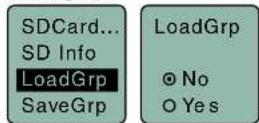
Save Frequency Group
Use UP and DOWN arrows to toggle and MENU/SEL to save group.

Setting Frame Rate

The frame rate affects embedding of the timing reference in the .BWF file metadata and display of time-code. The following options are available:
NOTE: While it is possible to change the frame rate, the most common use will be to check the frame rate which was received during the most recent timecode jam. In rare situations, it might be useful to alter the frame rate here, but be aware that audio tracks many not line up correctly with mismatched frame rates.
Use Clock

Choose to use the clock provided in the DPR as opposed to a timecode source. Set the clock in the Settings Menu, Date & Time.
NOTE: The DPR time clock and calendar (RTCC) cannot be relied on as an accurate time code
DPR-A
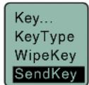
Key Menu
KeyType
The DPR receives an encryption key via the IR port from a key generating receiver (such as the Lectrosonics DCHR and DSQD receivers). Begin by selecting a key type in the receiver and generating a new key. Set the matching KEY TYPE in the DPR and transfer the key from the receiver (SYNC KEY) to the DPR via the IR ports. A confirmation message will display on the receiver display if the transfer is successful. The transmitted audio will then be encrypted and can only be decoded if the receiver has the matching encryption key.
The DPR has three options for encryption keys:
- Universal: This is the most convenient encryption option available. All encryption-capable Lectrosonics transmitters and receivers contain the Universal Key. The key does not have to be generated by a receiver. Simply set the DPR and a Lecrosonics receiver to Universal, and the encryption is in place. This allows for convenient encryption amongst multiple transmitters and receivers, but not as secure as creating a unique key.
- Shared: There are an unlimited number of shared keys available. Once generated by a receiver and transferred to the DPR, the encryption key is available to be shared (synced) by the DPR with other transmitters/receivers via the IR port. When a transmitter is set to this key type, a menu item named SEND KEY is available to transfer the key to another device.
- Standard: This is the highest level of security. The encryption keys are unique to the receiver and there are only 256 keys available to be transferred to a transmitter. The receiver tracks the number of keys generated and the number of times each key is transferred.
SendKey
This menu item is only available if Key Type is set to Shared. Press MENU/SEL to sync the Encryption key to another transmitter or receiver via the IR port.

Setup Menu
Setting Auto On


Selects whether or not the unit will turn on automatically after a battery change.
Enabling Remote Function


The DPR can be configured to respond to "dweedle tone" signals from the LectroRM smart phone app or to ignore them. Use the arrow buttons to toggle between
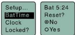
Setting Battery Timer
A built-in timer can be used with any battery type, but it is especially valuable with rechargeable batteries such as NiMH types. The voltage remains fairly constant across the discharge time of a rechargeable battery, then drops quickly near the end of the operating time. The most accurate way to determine runtime status is by testing the time provided by a particular battery brand and type, then using the timer to determine remaining runtime. Rechargeable batteries lose capacity over their life, so it is good to run the battery down and note the runtime on older or unfamiliar batteries.
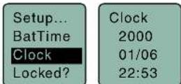
Setting Date and Time (Clock)
To set the date and time, use the MENU/SEL button to toggle through the fields and the UP and DOWN arrow buttons to choose the appropriate number.
Locking/Unlocking Settings
Changes to the settings can be locked to prevent inadvertent changes being made.

Backlit Settings
Sets the duration of the LCD backlight.

Turn LEDs On/Off
Enables/disables control panel LEDs.

NOTE: LEDs can also be turned off/on from the control panel. From the main screen, a quick press of the UP arrow button turns the control panel LEDs on. A quick press of the DOWN arrow button turns them off.
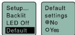
Restoring Default Settings
This is used to restore the factory settings.
About
DPR-A
LectroRM
By New Endlan LLC
LectroRM is a mobile application for iOS and Android operating systems. Its purpose is to remotely control Lectrosonics Transmitters, including:
- SM Series
• WM
• L Series
• DPR
The app remotely changes settings on the transmitter through the use of encoded audio tones, which when received by the attached microphone, will alter the configured setting. The app was released by New Endian, LLC in September 2011. The app is available for download and sells for \$25 on the Apple App Store and Google Play Store.
LectroRM's remote control mechanism is the use of an audio sequence of tones (dweedles) that are interpreted by the transmitter as a configuration change. The settings available in LectroRM are:
- Audio Level
- Frequency
- Sleep Mode
- Lock Mode
User Interface
The user interface involves selecting the audio sequence related to the desired change. Each version has an interface for selecting the desired setting and the desired option for that setting. Each version also has a mechanism to prevent accidental activation of the tone.
iOS

Android
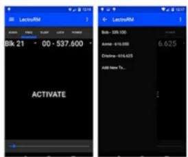
The Android version keeps all settings on the same page and allows the user to toggle between the activation buttons for each setting. The activation button must be long pressed to activate. The Android version also allows users to keep a configurable list of full sets of settings.
Activation
For a transmitter to respond to remote control audio tones, the transmitter must meet certain requirements:
- The transmitter must not be turned off; it can however be in sleep mode.
- The transmitter microphone must be within range.
- The transmitter must be configured to enable remote control activation.
Please be aware this app is not a Lectrosonics product. It is privately owned and operated by New Endian LLC, www.newendian.com.
Replacement Parts and Accessories
21750 Barrel Adapter
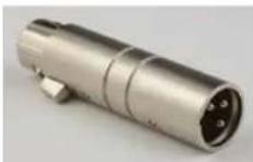
This polarity reversing adapter may be needed to correct for asymmetrical current draw in some P48 powered condenser microphones, including older Neumann 100 Series, Rode NTG3 and others. If your microphone does not power on correctly when used with these transmitters, insert the adapter between the transmitter and microphone.
5510 Flash Memory Card
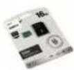
Flash Memory Card. MicroSDHC toSD Adapter included.
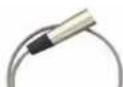
AMM(xx)
Whip antenna; straight. Specify frequency block (see chart below). Included with unit at purchase.

MCA-M30 Barrel Adapter
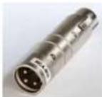
Mic adapter for Earthworks M30 microphone with HM, DPR and UH400a/TM transmitters.
This adapter may be needed if you are experiencing noise or distortion with measurement microphones, particularly the
Earthworks M30. The adapter has a common mode choke for suppressing RF noise. If your microphone signal exhibits the problems listed above when connected to a UH400, HM or DPR transmitter, insert the adapter between the microphone and the transmitter. Insert the adapter between the transmitter and microphone to alleviate these issues.
MCA5X


This is an optional adapter for connecting a lavaliere microphone to the DPR or HM transmitters. TASM to XLR3-M connectors. Passes transmitter phantom power to bias the electret lavaliere microphone. Includes zener protection to limit bias voltage to protect the microphone if transmitter phantom power is set too high.
MCA-TPOWER
This cable adapter is to be used with the UH200D, UH400, HM and DPR plug-on transmitters
DPR-A
Specifications and Features
Transmitter
Operating Frequencies: US: 470.100 - 607.950 MHz
Frequency Selection Steps: 25 kHz
RF Power output: Selectable 25/50 mW
Frequency stability: ± 0.002%
Digital modulation: 8PSK
Spurious radiation: Compliant with
ETSI EN 300 422-1 V1.4.2
Equivalent input noise: -125 dBV
(A-weighted)
Input level: Nominal 2 mV to 300 mV,
before limiting
Greater than 1V maximum, with limiting
Input impedance: 1K Ohm
Input limiter: Dual envelope type; 30 dB range
Gain control range: 55 dB in 1 dB steps; digital control
Modulation Indicators: • Dual bi-color LEDs indicate
modulation of -20, -10, 0, +10 dB
referenced to full modulation
- LCD bar graph
Encryption:
AES 256-CTR
(per FIPS 197 and FIPS 140-2)
Audio Performance:
Frequency Response:
Low frequency Roll-off:
100, 120 and 150 Hz
Input Dynamic Range:
125 dB (with full Tx limiting)
Controls & Indicators:
• LED audio level indicators
Audio Input Jack
Phanlom Power: 5V @ 18 mA max., 15V @ 15 mA max.
and 48 V @ 4 mA max., plus "OFF"
IR (Infrared) port: For quick setup by transferring settings
from an IH enabled receiver
Antenna: External SMA antenna jack
Battery: Two 1.5 Volt AA (lithium recommended)
Battery Life: AA Lithium, 48v phantom power
engaged:
Recorder
Storage media: microSDHC memory card (HC Type)
File format: .wav files (BWF)
A/D converter: 24-bit
Sampling rate: 48 kHz
Recording modes/Bit rate: HD mono: 24 bit - 144 kb/s
Input:
Type: Analog micrline level compatible; servo bias
preamp for 2V and 4V lavallere microphones
Input level: • Dynamic mic: 0.5 mV to 50 mV
• Electret mic: Nominal 2 mV to 300 mV
• Line level: 17 mV to 1.5 V
Input connector: TA5M 5-pin male
Timecode:
Connector: 3.5 mm TRS
Signal voltage: 0.5 Vp-p to 5 Vp-p
Input impedance: 10 k Ohms
Format: SMPTE 12M - 1999 compliant
Audio Performance:
Frequency response: 25 Hz to 20 kHz; +0.5/-1.5 dB
Dynamic range: 110 dB (A), before limiting
125 dB (with full Tx limiting)
Distortion: < 0.035%
Operating temperature range:
Celsius: -20 to 50
Firmware updates are made using a microSDHC memory card. Download and copy the following firmware update files to a drive on your computer.
- dprMXXX.hex is the microcontroller file, where "XXX" is the revision number.
- dprFXXX.mcs Is the FPGA file, where "XXX" Is the revision number.
In the computer:
1) Perform a Quick Format of the card. On a Windows-based system, this will automatically format the card to the FAT32 format, which is the Windows standard. On a Mac, you may be given several options. If the card is already formatted in Windows (FAT32) - it will be greyed out - then you do not need to do anything. If the card is in another format, choose Windows (FAT32) and then click "Erase". When the quick format on the computer is complete, close the dialogue box and open the file browser.
2) Copy the dpr vX_xx.ldr file to the memory card, then safely eject the card from the computer.
In the DPR:
1) Leave the DPR turned off and insert the microS-DHC memory card into the slot.
2) Hold down both the UP and DOWN arrow buttons on the control panel and turn the power on.
3) The transmitter will boot up into the firmware update mode with the following options on the LCD:
- Update - Displays a scrollable list of the .ldr files on the card.
- Power Off - Exits the update mode and turns the power off.
7) If you re-insert the update card and turn the power back on for normal use, the LCD will display a message prompting you to format the card:
Format Card?
(files lost)
• No
• Yes
If you wish to record audio on the card, you must re-format it. Select Yes and press MENU/SEL to format the card. When the process is complete, the LCD will return to the Main Window and be ready for normal operation.
If you choose to keep the card as is, you may remove the card at this time.
The firmware update process is managed by a bootloader program - on very rare occasions, you might need to update the bootloader.
WARNING: Updating the bootloader can corrupt your unit if interrupted. Don't update the bootloader unless advised to do so by the factory.
- dprbootX.hex is the bootloader file, where "X" is the revision number.
Follow the same process as with a firmware update and select the dprboot file.
DPR-A
Recovery Process
In the event of a battery failure while the unit is recording, a recovery process is available to restore the recording in proper format. When a new battery is installed and the unit is turned back on, the recorder will detect the missing data and prompt you to run the recovery process. The file must be recovered or the card will not be usable in the DPR.
First it will read:
Interrupted Recording
Found
The LCD message will ask:
Recover?
for safe use
see manual
You will have the choice of No or Yes (No is selected as the default). If you wish to recover the file, use the DOWN arrow button to select Yes, then press MENU/SEL.
The next window will give you the option to recover all or part of the file. The default times shown are the best guess by the processor where the file stopped recording. The hours will be highlighted and you can either accept the value shown or select a longer or shorter time. If you are unsure, simply accept the value shown as the default.
Press MENU/SEL and the minutes are then highlighted. You can increase or decrease the time to be recovered. In most cases you can simply accept the values shown and the file will be recovered. After you have made your time choices, press MENU/SEL again. A small GO! symbol will appear next to the DOWN arrow button. Pressing the button will initiate the file recovery. The recovery will happen quickly and you will see:
Recovery
Successful
Service and Repair
If your system malfunctions, you should attempt to correct or isolate the trouble before concluding that the equipment needs repair. Make sure you have followed the setup procedure and operating instructions. Check the interconnecting cables and then go through the Troubleshooting section in this manual.
We strongly recommend that you do not try to repair the equipment yourself and do not have the local repair shop attempt anything other than the simplest repair. If the repair is more complicated than a broken wire or loose connection, send the unit to the factory for repair and service. Don't attempt to adjust any controls inside the units. Once set at the factory, the various controls and trimmers do not drift with age or vibration and never require readjustment. There are no adjustments inside that will make a malfunctioning unit start working.
LECTROSONICS' Service Department is equipped and staffed to quickly repair your equipment. In warranty repairs are made at no charge in accordance with the terms of the warranty. Out-of-warranty repairs are charged at a modest flat rate plus parts and shipping. Since it takes almost as much time and effort to determine what is wrong as it does to make the repair, there is a charge for an exact quotation. We will be happy to quote approximate charges by phone for out-of-warranty repairs.
Returning Units for Repair
For timely service, please follow the steps below:
A. DO NOT return equipment to the factory for repair without first contacting us by email or by phone. We need to know the nature of the problem, the model number and the serial number of the equipment. We also need a phone number where you can be reached 8 A.M. to 4 P.M. (U.S. Mountain Standard Time).
B. After receiving your request, we will issue you a return authorization number (R.A.). This number will help speed your repair through our receiving and repair departments. The return authorization number must be clearly shown on the outside of the shipping container.
C. Pack the equipment carefully and ship to us, shipping costs prepaid. If necessary, we can provide you with the proper packing materials. UPS is usually the best way to ship the units. Heavy units should be "double-boxed" for safe transport.
D. We also strongly recommend that you insure the equipment, since we cannot be responsible for loss of or damage to equipment that you ship. Of course, we insure the equipment when we ship it back to you.
Lectrosonics USA:
Mailing address: Shipping address: Telephone:
Lectrosonics, Inc. Lectrosonics, Inc. (505) 892-4501
PO Box 15900 561 Laser Rd., Suite 102 (800) 821-1121 Toll-free
Rio Rancho, NM 87174 Rio Rancho, NM 87124 (505) 892-6243 Fax
USA USA
LIMITED ONE YEAR WARRANTY
The equipment is warranted for one year from date of purchase against defects in materials or workmanship provided it was purchased from an authorized dealer. This warranty does not cover equipment which has been abused or damaged by careless handling or shipping. This warranty does not apply to used or demonstrator equipment.
Should any defect develop, Lectrosonics, Inc. will, at our option, repair or replace any defective parts without charge for either parts or labor. If Lectrosonics, Inc. cannot correct the defect in your equipment, it will be replaced at no charge with a similar new item. Lectrosonics, Inc. will pay for the cost of returning your equipment to you.
This warranty applies only to items returned to Lectrosonics, Inc. or an authorized dealer, shipping costs prepaid, within one year from the date of purchase.
This Limited Warranty is governed by the laws of the State of New Mexico. It states the entire liability of Lectrosonics Inc. and the entire remedy of the purchaser for any breach of warranty as outlined above. NEITHER LECTROSONICS, INC. NOR ANYONE INVOLVED IN THE PRODUCTION OR DELIVERY OF THE EQUIPMENT SHALL BE LIABLE FOR ANY INDIRECT, SPECIAL, PUNITIVE, CONSEQUENTIAL, OR INCIDENTAL DAMAGES ARISING OUT OF THE USE OR INABILITY TO USE THIS EQUIPMENT EVEN IF LECTROSONICS, INC. HAS BEEN ADVISED OF THE POSSIBILITY OF SUCH DAMAGES. IN NO EVENT SHALL THE LIABILITY OF LECTROSONICS, INC. EXCEED THE PURCHASE PRICE OF ANY DEFECTIVE EQUIPMENT.
This warranty gives you specific legal rights. You may have additional legal rights which vary from state to state.


- Table of Contents
- General Technical Description
- Low Frequency Roll-Off
- Input Limiter
- Control Panel
- Alternate Recording Function
- Encryption
- Features
- LCD Screen
- Power LED
- Key LED
- MENU/SEL Button
- BACK Button
- UP/DOWN Arrow Buttons
- Menu Shortcuts
- Audio Input Jack
- Battery Installation
- Attaching/Removing a Microphone
- Turning Power ON
- Powering On in Operating Mode
- Powering On in Standby Mode
- Transmitter Operating Instructions
- Recorder Operating Instructions
- Formatting SD Card
- IMPORTANT
- iXML HEADER SUPPORT
- Compatibility with microSDHC memory cards
- DPR Menu
- Setup Screen Details
- Main Window Indicators
- Turning Control Panel LEDs ON/OFF
- Helpful Features on Receivers
- Input Menu
- Adjusting the Input Gain
- Selecting the Low Frequency Roll-off
- Selecting Audio Polarity (Phase)
- Selecting Phantom Power Supply
- About the Phantom Power Supply
- Xmit Menu
- Selecting Frequency
- Setting Transmitter Output Power
- Turning Rf Output On
- Choosing Files for Replay
- Choosing Takes for Replay
- Setting Scene and Take Number
- Formatting microSDHC Memory Card
- microSDHC Memory Card Info
- Load Frequency Group
- Save Frequency Group
- Setting Frame Rate
- Use Clock
- Key Menu
- KeyType
- SendKey
- Setup Menu
- Setting Auto On
- Enabling Remote Function
- Setting Battery Timer
- Setting Date and Time (Clock)
- Locking/Unlocking Settings
- Backlit Settings
- Turn LEDs On/Off
- Restoring Default Settings
- About
- LectroRM
- By New Endlan LLC
- User Interface
- Android
- Activation
- Replacement Parts and Accessories
- Specifications and Features
- Transmitter
- Recorder
- In the computer:
- In the DPR:
- Format Card?
- (files lost)
- • No
- • Yes
- Recovery Process
- Interrupted Recording
- Found
- Recover?
- for safe use
- see manual
- Recovery
- Successful
- Service and Repair
- Returning Units for Repair
- Lectrosonics USA:
- LIMITED ONE YEAR WARRANTY
Brand : Lectrosonics
Model : DPR-A
Category : Audio transceiver