
MTCR - Audio transceiver Lectrosonics - Free user manual and instructions
Find the device manual for free MTCR Lectrosonics in PDF.

| Product Type | Audio Transceiver |
| Brand | Lectrosonics |
| Model | MTCR |
| Dimensions (approx.) | 100 x 60 x 20 mm |
| Weight (approx.) | 150 g (without batteries) |
| Power Supply | 2 x AA batteries (1.5V each) or rechargeable NiMH |
| Frequency Range | 470 – 614 MHz (UHF) |
| Modulation | FM |
| Audio Input Connector | 3.5 mm (1/8 inch) stereo jack |
| Audio Output Connector | 3.5 mm (1/8 inch) stereo jack |
| Main Functions | Transmit and receive audio signals wirelessly |
| Maintenance | Clean with dry, soft cloth; avoid liquids |
| Safety Precautions | Keep away from water and extreme temperatures; do not disassemble |
| Spare Parts Available | Batteries, antenna, belt clip |
| Repairability | Serviceable by authorized technician; user-replaceable batteries |
| General Information | Compact and rugged design suitable for field use |
Frequently Asked Questions - MTCR Lectrosonics
User questions about MTCR Lectrosonics
0 question about this device. Answer the ones you know or ask your own.
Ask a new question about this device
Download the instructions for your Audio transceiver in PDF format for free! Find your manual MTCR - Lectrosonics and take your electronic device back in hand. On this page are published all the documents necessary for the use of your device. MTCR by Lectrosonics.
USER MANUAL MTCR Lectrosonics
microSDHC Logo is a trademark of SD-3C, LLC
Follow Us On:


Fill in for your records:
Serial Number:
Purchase Date:
Quick Start Steps
1) Install good battery and turn the power on (p. 3, 6).
2) Insert microSDHC memory card and format it with the MTCR (p. 3, 4).
3) Timecode jam source (p. 7, 8).
4) Connect microphone or audio source.
5) Set input gain (Mic Level p. 8).
6) Select record mode (p. 9).
7) Set output level (HP Volume p. 8).
8) Begin recording (p. 5-9).
CAUTION: See card formatting warning on page 4.

Table of Contents
Quick Start Steps....1
Introduction......2
Broadcast Wave Format....2
Versatility....2
Battery Installation....3
Compatibility withmicroSDHC memory cards....3
Installing the Card 4
Formatting the SD Card 4
IMPORTANT 4
iXML HEADER SUPPORT 4
Features and Controls 5
Operating Instructions....6
Powering On 6
Powering Off 6
Main Window....6
Recording Window....6
Playback Window....6
Navigating Menus....7
Timecode....8
Mic Level 8
HP Volume 8
Scene & Take 8
SD Card....8
Settings....9
Firmware Updates 9
Recovery Process 10
Copying Recordings to a Computer....11
PDRRemote....12
5-Pin Input Jack Wiring 13
Microphone Cable Termination for Non-Lectrosonics Microphones.... 14
Timecode Jack Wiring....14
Wiring Hookups for Different Sources 15
Included Accessories....16
Additional Accessories....16
Specifications 17
Available Recording Time 17
Service and Repair 19
Returning Units for Repair 19
Introduction
Congratulations on your purchase of the MTCR Digital Recorder. On occasion, there is a need to record audio in circumstances where a traditional full sized recorder is impractical. Whether it be an extreme sport, a public speaking event, a wedding or a next-to-impossible location sound recording, the MTCR is designed for the difficult audio capture. When talent is at an extreme distance or using a wireless microphone is not practical (knights in armor come to mind), the MTCR can travel with your subject and record professional quality audio, synchronized with timecode. The recorder is unobtrusive and easily hidden in garments and costumes and easy to conceal when used as a “plant” microphone to capture environmental or location sound.
Broadcast Wave Format
With a timecode jam at the start of the production, the audio data file contents include a timing reference to make it easy to synchronize them in the timeline. The industry standard BWF/.WAV file format is compatible with essentially any audio or video editing software.
Versatility
The MTCR can be tethered to a camera to capture a higher quality or backup audio recording. The input connector is the industry standard TA5M jack that accepts any mic or line level signal, and provides bias voltage to power a wide variety of electret lavaliere microphones. The input connection and wiring is compatible with microphones pre-wired for “compatible” and “servo bias” configurations to feed 5-pin inputs on Lectrosonics wireless microphone transmitters.
Setup and adjustment is made through an intuitive interface provided by the keypad and LCD. In keeping with typical Lectrosonics mechanical designs, the housing is machined from a solid aluminum billet for the ruggedness needed in field production.
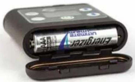
Battery Installation
The audio recorder is powered by a single AAA Lithium battery for 6 hours of operation.
Zinc-carbon batteries marked "heavy-duty" or "long-lasting" are not adequate.
NOTE: Although alkaline batteries will work in the MTCR, we strongly recommend that they be used only for short-term testing. For any actual production use, we recommend the use of disposable lithium AAA batteries.
Push inward on the release tabs to open the door.
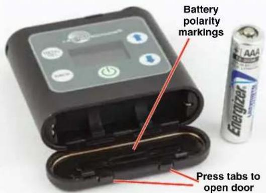
Insert the battery according to the markings inside the battery compartment door. The (+) pos. end of the battery is oriented as shown here.
natural_image
Black cylindrical battery with attached case showing internal components (no visible text or symbols)CAUTION: Danger of explosion if battery is incorrectly replaced. Replace only with the same or equivalent type.
Compatibility with microSDHC memory cards
Please note that the MTCR and SPDR are designed for use with the microSDHC memory cards. There are several types of SD card standards (as of this writing) based on capacity (storage in GB).
SDSC: standard capacity, up to and including 2 GB – DO NOT USE!
SDHC: high capacity, more than 2 GB and up to and including 32 GB – USE THIS TYPE.
SDXC: extended capacity, more than 32 GB and up to and including 2 TB - DO NOT USE!
SDUC: extended capacity, more than 2TB and up to and including 128 TB – DO NOT USE!
The larger XC and UC cards use a different formatting method and bus structure and are NOT compatible with the MTCR recorder. These are typically used with later generation video systems and cameras for image applications (video and high resolution, high speed photography).
ONLY microSDHC memory cards should be used. They are available in capacities from 4GB to 32GB. Look for the Speed Class 10 cards (as indicated by a C wrapped around the number 10), or the UHS Speed Class I cards (as indicated by the numeral 1 inside a U symbol). Also note the microSDHC Logo.
If you are switching to a new brand or source of card, we always suggest testing first before using the card on a critical application.
The following markings will appear on compatible memory cards. One or all of the markings will appear on the card housing and the packaging.
Speed Class 10

UHS Speed Class 1

UHS Speed Class I

Stand-alone


UHS Speed Class I
Accompanying microSDHC logo
microSDHC Logo Is a trademark of SD-3C, LLC
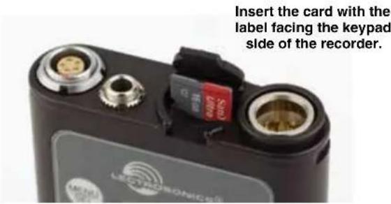
Installing the Card
The card slot is covered by a flexible cap. Open the cap by pulling out on the side flush with the housing.

natural_image
Close-up of a black electronic component with multiple ports and connectors (no visible text or symbols)Pull up on this side of cap to open
Formatting the SD Card
New microSDHC memory cards come pre-formatted with a FAT32 file system which is optimized for good performance. The MTCR relies on this performance and will never disturb the underlying low level formatting of the SD card. When the MTCR “formats” a card, it performs a function similar to the Windows “Quick Format” which deletes all files and prepares the card for recording. The card can be read by any standard computer but if any write, edit or deletions are made to the card by the computer, the card must be re-formatted with the MTCR to prepare it again for recording. The MTCR never low level formats a card and we strongly advise against doing so with the computer.
To format the card with the MTCR, select Format Card in the menu and press MENU/SEL on the keypad.
NOTE: An error message will appear if samples are lost due to a poor performing "slow" card.
WARNING: Do not perform a low level format (complete format) with a computer. Doing so may render the memory card unusable with the MTCR recorder.
With a windows based computer, be sure to check the quick format box before formatting the card.
With a Mac, choose MS-DOS (FAT).
IMPORTANT
The formatting of the MTCR SD card sets up contiguous sectors for maximum efficiency in the recording process. The file format utilizes the BEXT (Broadcast Extension) wave format which has sufficient data space in the header for the file information and the time code imprint.
The SD card, as formatted by the MTCR, can be corrupted by any attempt to directly edit, change, format or view the files on a computer.
The simplest way to prevent data corruption is to copy the .wav files from the card to a computer or other Windows or OS formatted media FIRST. Repeat - COPY THE FILES FIRST!
Do not rename files directly on the SD card.
Do not attempt to edit the files directly on the SD card.
Do not save ANYTHING to the SD card with a computer (such as the take log, note files etc) - it is formatted for MTCR use only.
Do not open the files on the SD card with any third party program such as Wave Agent or Audacity and permit a save. In Wave Agent, do not IMPORT - you can OPEN and play it but do not save or Import - Wave Agent will corrupt the file.
In short - there should be NO manipulation of the data on the card or addition of data to the card with anything other than a MTCR. Copy the files to a computer, thumb drive, hard drive, etc. that has been formatted as a regular OS device FIRST - then you can edit freely.
iXML HEADER SUPPORT
Recordings contain industry standard iXML chunks in the file headers, with the most commonly used fields filled in.
Features and Controls

The audio input circuitry is the essentially the same as on Lectrosonics SM and L Series transmitters. Any microphone wired as Lectrosonics "compatible" or "servo bias" will work with the MTCR. See page 10 for details.
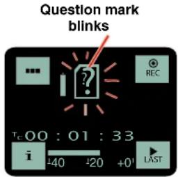
If the unit is powered on with a card which hasn't been formatted for the MTCR, a prompt to format the card will appear. Follow the on-screen instructions to format the card. If the card has an interrupted recording on it, the Recovery screen will appear.
If there is no card in the MTCR or the card is not properly formatted, the Main Window appears. Settings are accessed by pressing MENU/SEL on the keypad, and then using the UP and DOWN arrow buttons and BACK button to navigate the menu items and select functions. The buttons also provide alternate functions as labeled by the icons on the LCD.
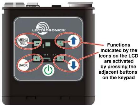
Icons in each corner of the LCD define the alternate functions of the adjacent buttons on the keypad. For example, in the Main Window shown above, recording is started by pressing the UP arrow button on the keypad, in which case, the display switches to the Recording Window.
In the Recording Window, the functions of three keypad buttons change to provide the needed operations during recording.


In the Playback Windows, the icons on the LCD change to provide the functions needed during playback. There are three variants of the playback window:
• active playback
• paused playback in the middle of the recording
• paused playback at the end of the recording
The icons in the corners of the LCD will change depending on the status of the playback.

NOTE: Refer to the Operating Instructions section for details on the specific button functions and operations in the Main, Recording and Playback Windows.
Operating Instructions
Powering On
Press and hold the Power Button until the Lectrosonics logo appears on the LCD.
Powering Off
Power can be turned off by holding the Power Button in and waiting for the countdown. The Power Button will not work while the unit is recording (stop recording first before powering down) or if the front panel has been locked out by the operator (unlock the front panel first).
If the power button is released before the countdown reaches 3, the unit will remain turned on and the LCD will return to the same screen or menu that was displayed previously.
Main Window
The Main Window provides a view of the battery status, timecode and the input audio level. Icons in the four corners of the screen provide access to the Menu, Info (available recording time if SD card installed, MTCR info if no card in unit), and the REC (record start) and LAST (play last clip) functions. These functions are invoked by pressing the adjacent keypad button as shown on the previous page.

The Main Window will alert you if there is no memory card in the MTCR.
Recording Window
To start recording, press the REC button in the top right corner of the Main Window. The screen will switch to the Recording Window.
NOTE: The headphone output will be muted when recording.

About the "Slow Card" Warning:
If any samples are lost during recording, a warning screen will appear displaying "slow card." Typically the lost audio is less than 10 milliseconds and is barely noticeable. The unit will still be recording while this screen appears. Press the BACK button (OK) to return to the recording screen.
When this happens, there will be no “gap” or brief silence in the recording. Instead, the audio and timecode will simply jump forward. If this happens repeatedly during the recording, it is best to replace the card.
Playback Window
Icons in the Playback Window provide button functions used for playback on a recording device. The icons will change depending on the status of the playback: active playback, paused in the middle, or paused at the end.

All files created are given a time stamp. See File Naming for options.
![002A .WAV 02/05 05:01 [PDR-HD24] Len 00:00:11 Tc00 : 18 : 11](/content/2026/06/1194471/images/1d2460f4768c1945b0470d794ba04f27d50ce89745c099feaf9d924e22eced8f.jpg)
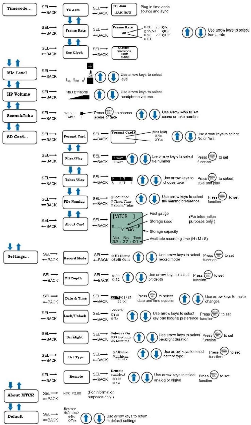
Navigating Menus
flowchart
graph TD
    A["Timecode..."] --> B["SEL"] --> C["TC Jam"]
    C --> D["Frame Rate"]
    D --> E["SEL"] --> F["SET"]
    F --> G["Use Clock"]
    G --> H["LOADING TIMECODE FROM CLOCK"]
    H --> I["HP Volume"]
    I --> J["SEL"] --> K["HEADPHONE"]
    K --> L["Text: Scene: Take 1"]
    L --> M["Format Card"]
    M --> N["SETS/Play"]
    N --> O["Text: Takes/Play"]
    O --> P["File Naming"]
    P --> Q["About Card"]
    Q --> R["[MTCR"]]
    R --> S["Fuel gauge"]
    S --> T["Storage used (For information purposes only.)"]
    T --> U["Storage capacity"]
    U --> V["Available recording time (H : M : S)"]
    V --> W["Settings..."]
    W --> X["SEL"] --> Y["Record Mode"]
    Y --> Z["SELE"]
    Z --> AA["Bit Depth"]
    AA --> AB["Date & Time"]
    AB --> AC["SELE"]
    AC --> AD["Lock/Unlock"]
    AD --> AE["Backlight"]
    AE --> AF["Bat Type"]
    AF --> AG["Remote"]
    AG --> AH["About MTCR"]
    AH --> AI["Default"]

    subgraph Timecode
        B --> B1["←BACK"]
        C --> C2["←BACK"]
        D --> D3["←BACK"]
        E --> E4["←BACK"]
        F --> F5["←BACK"]
        G --> G6["←BACK"]
        H --> H1["←BACK"]
        I --> I1["I40 I20+0↑"]
        J --> J1["←BACK"]
        K --> K1["←BACK"]
        L --> L1["←BACK"]
        M --> M1["←BACK"]
        N --> N1["←BACK"]
        O --> O1["←BACK"]
        P --> P1["←BACK"]
        Q --> Q1["←BACK"]
        R --> R1["←BACK"]
        S --> S1["←BACK"]
        T --> T1["←BACK"]
        U --> U1["←BACK"]
        V --> V1["←BACK"]
        W --> W1["←BACK"]
        X --> X1["←BACK"]
        Y --> Y1["←BACK"]
        Z --> Z1["←BACK"]
        AA --> AA1["←BACK"]
        AB --> AB1["←BACK"]
        AC --> AC1["←BACK"]
        AD --> AD1["←BACK"]
        AE --> AE1["←BACK"]
        AF --> AF1["←BACK"]
        AG --> AG1["←BACK"]
        AH --> AH1["←BACK"]
        AI --> AI1["←BACK"]
        AJ["Rev: v2.00 (For information purposes only.)"] --> AK["Restore defaults? @No ○Yes ↑ ↓ Use arrow keys to return to default settings"]

    subgraph Timecode
        B --> AL["SEL"] --> AM["TC Jam"]
        C --> AN["Frame Rate"]
        D --> AO["SEL"] --> AP["SET"]
        E --> AQ["Use Clock"]
        F --> AR["LoadING TIMECODE FROM CLOCK"]
        H --> AS["Plug in time code source and sync"]
        I --> AT["Image of Frame Rate 30: 29.97 30DF 29.98DF 24"] --> AU[Use arrow keys to select frame rate ↑ ↓ Use arrow keys to select interface level ↑ ↓ Use arrow keys to select headphone volume ↑ ↓ Use arrow keys to select telephone volume ↑ ↓ Use arrow keys to select telephone volume ↑ ↓ Use arrow keys to select telephone volume ↑ ↓ Use arrow keys to select telephone volume ↑ ↓ Use arrow keys to select telephone volume ↑ ↓ Use arrow keys to select telephone volume ↑ ↓ Use arrow keys to select telephone volume ↑ ↓ Use arrow keys to select telephone volume ↑ ↓ Use arrow keys to select telephone volume ↑ ↓ Use arrow keys to select telephone volume ↑ ↓ Use arrow keys to select telephone volume ↑ ↓ Use arrow keys to select telephone volumes ↑ ↓ Use arrow keys to select telephone volumes ↑ ↓ Use arrow keys to select telephone volumes ↑ ↓ Use arrow keys to select telephone volumes ↑ ↓ Use arrow keys to select telephone volumes ↑ ↓ Use arrow keys to select telephone volumes ↑ ↓ Use arrow keys to select telephone volumes ↑ ↓ Use arrow keys to select telephone volumes ↑ ↓ Use arrow keys to select telephone volumes ↑ ↓ Use arrow keys to select telephone volumes ↑ ↓ Use arrow keys to select telephone volumes ↑ ↓ Use arrow keys to select telephone volumes
    end
Rio Rancho, NM
Timecode...
TC Jam (jam timecode)
When TC Jam is selected, JAM NOW will flash on the LCD and the unit is ready to be synced with the time-code source. Connect the timecode source and the sync will take place automatically. When the sync is successful, a message will be displayed to confirm the operation.
NOTE: The headphone output will be muted when entering the TC Jam page. Audio will be restored when the cable is removed.
Timecode defaults to zero at power up if no timecode source is used to jam the unit. A timing reference is logged into the BWF metadata.
Frame Rate
The frame rate affects embedding of the timing reference in the BWF file metadata and display of timecode. The following options are available:
NOTE: While it is possible to change the frame rate, the most common use will be to check the frame rate which was received during the most recent timecode jam. In rare situations, it might be useful to alter the frame rate here, but be aware that audio tracks many not line up correctly with mismatched frame rates.
Use Clock
Choose to use the clock provided in the MTCR as opposed to a timecode source. Set the clock in the Settings Menu, Date & Time on page 9.
NOTE: The MTCR time clock and calendar (RTCC) cannot be relied on as an accurate time code source. Use Clock should only be used in projects where there is no need for the time to agree with an external time code source.
Mic Level

C or L appears here
Use the UP and DOWN arrow buttons to adjust the input gain. When the audio level meter reading exceeds the zero at the top, either a "C" or an "L" icon will appear, indicating respectively clipping in the non-safety track (Split Gain mode) or limiting (HD Mono mode). In HD
Mono mode, the limiter compresses 30 dB of input level into the top 5 dB, reserved for "overhead" in this mode. In Split Gain mode, the limiter would rarely be engaged, but it will engage if necessary (with no graphical indication) to prevent clipping of the safety track.
NOTE: See Record Mode.
HP Volume
Use UP and DOWN arrows to adjust headphone volume.
Scene & Take
Each time recording is started, the MTCR automatically begins a new take. Takes can run up to 999. The scene numbers can be manually entered and are limited to 99.
SD Card...
Format Card
This item erases all files on the card and prepares the card for recording.
Files/Play
Choose to play the files based on their name. Use the arrows to scroll, MENU/SEL to select the file and the DOWN arrow to play.
Takes/Play
Choose to play the files based on scene and take. Scene and take numbers can be manually entered, and are embedded in the filenames and iXML headers of recordings. Take number automatically increments each time the record button is pressed. When browsing by scene and take, recordings that span multiple files are listed singly and played as one long recording.
File Naming
Filenames of the recordings contain industry standard iXML chunks in the file headers, with the most commonly used fields filled in. File naming can be set as:
- Sequence: a progressive sequence of numbers
- Clock Time: the time of the internal clock at the beginning of the recording; recorded as DDHHM-MA.WAV. DD is the day of the month, HH is hours, MM is minutes, A is the overwrite-prevention character, incrementing to 'B', 'C', etc. as needed to avoid a naming conflict A final character serves as the segment identifier, being absent in the first segment, '2' in the second segment, '3' in the third and so on.
- Scene/Take: the progressive scene and take automatically cataloged each time a recording is begun; S01T001.WAV. The initial 'S' is meant to suggest "Scene" but also serves as the overwrite prevention character, decrementing to 'R', 'Q', etc. as needed to avoid a naming conflict. The "01" after the 'S' is the scene number. 'T' means take, and the "001" is the take number. An eighth character is used only for the second and subsequent (4 GB) segments for very large recordings. Scene numbers are entered manually. Take numbers increment automatically.
About Card
View information about the microSDHC memory card. See storage used, storage capacity and available recording time.

Settings...
Record Mode
There are two recording modes available in the menu, HD Mono, which records a single audio track and Split Gain, which records two different tracks, one at the normal level and another at -18 dB as a "safety" track that can be used in place of the normal track in the event that overload distortion (clipping) has occurred on the normal track. In either mode, recordings over 4GB are broken into sequential segments so very long recordings (over approx 5 hours in HD mode or 2.5 hours in split mode) will not be a single file.
NOTE: See Mic Level.
NOTE: The headphone output will be muted when recording.
Bit Depth
MTCR defaults to 24-bit format recording, which is a more efficient space saving format. 32-bit is available if your editing software is older and won't accept 24-bit. (32-bit is actually 24-bit padded with zeros, so more space is taken up on the card.)
Date & Time
The MTCR has a real time clock/calendar (RTCC) which is used for timestamping the files it writes to the SD card. The RTCC is able to keep time for a minimum of 90 minutes with no battery installed, and can keep time more or less indefinitely if any battery, even a "dead" battery, is installed. To set the date and time, use the MENU/SEL button to toggle through the options and the UP and DOWN arrow buttons to choose the appropriate number.
WARNING: Since the real time clock/calendar can be manipulated and/or stop with loss of power, it should not be relied upon for accurate time keeping. Only use this option when a time clock is not available.
Lock/Unlock
The LOCKED mode protects the recorder from accidental changes to its settings. When locked, menu navigation is possible, but any attempt to alter settings will prompt a "LOCKED/can use menu to unlock" message. The unit can be unlocked using the Lock/Unlock setup screen. The "dweedle tone" remote control will still work.
Backlight
The recorder backlight can be set to turn off after either 5 minutes or 30 seconds, or to stay on continuously.
Bat Type
Choose either Alkaline or Lithium battery type. The voltage of the installed battery will be shown at the bottom of the display.
NOTE: Although alkaline batteries will work in the MTCR, we strongly recommend that they be used only for short-term testing. For any actual production use, we recommend the use of disposable lithium AAA batteries.
Remote
The recorder can be configured to respond to "dweedle tone" signals from the PDRRemote app or to ignore them. Use the arrow buttons to toggle between "yes" (remote control on) and "no" (remote control off). The default setting is "no."
About MTCR
The MTCR's firmware version and serial number are displayed.
Default
To return the recorder to its factory default settings, use the UP and DOWN arrow buttons to choose Yes.
Firmware Updates
Firmware updates are made using a microSDHC memory card. Download and copy the following firmware update files to a drive on your computer.
- MTCR vX_xx.ldr is the firmware update file, where "X_xx" is the revision number.
In the computer:
1) Perform a Quick Format of the card. On a Windows-based system, this will automatically format the card to the FAT32 format, which is the Windows standard. On a Mac, you may be given several options. If the card is already formatted in Windows (FAT32) - it will be greyed out - then you do not need to do anything. If the card is in another format, choose Windows (FAT32) and then click "Erase." When the quick format on the computer is complete, close the dialogue box and open the file browser.
2) Copy the MTCR v1_xx.ldr file to the memory card, then safely eject the card from the computer.
In the MTCR:
1) Leave the MTCR turned off and insert the microSDHC memory card into the slot.
2) Hold down both the UP and DOWN arrow buttons on the recorder and turn the power on.
continued on next page...
3) The recorder will boot up into the firmware update mode with the following options on the LCD:
- Run - Exits the update mode and starts up the recorder in the normal operating mode.
- Update - Displays a scrollable list of the .Idr files on the card.
- Power Off - Exits the update mode and turns the power off.
NOTE: If the unit powers on normally instead of offering the options in Step 3 (above), power the unit off and try again, making sure that both arrow buttons are firmly depressed while powering the unti back on.
4) Select Update. Use the UP and DOWN arrow buttons to select the desired file and press MENU/SEL to begin the update process. The LCD will display status messages while the firmware is being updated.
NOTE: The Update process takes about 20 seconds.
5) When the update is complete, the LCD will display this message: UPDATE SUCCESSFUL REMOVE CARD. After the card is removed, the LCD will return to the three options shown in step 3 above.
6) Select Power Off and press MENU/SEL to finish the update.
7) If you re-insert the same card and turn the power back on for normal use, the LCD will display a message prompting you to format the card:
Format Card?
(files lost)
• No
• Yes
If you wish to record audio on the card, you must re-format it. Select Yes and press MENU/SEL to format the card. When the process is complete, the LCD will return to the Main Window and be ready for normal operation.
If you choose to keep the card as is, you may remove the card at this time.
The firmware update process is managed by a bootloader program - on very rare occasions, you might need to update the bootloader.
- MTCRboot vX_xx.ldr is the bootloader file
Follow the same process as with a firmware update and select the MTCRboot file. Be forewarned, this can corrupt your unit if interrupted. Don't update the bootloader unless advised to do so by the factory.
Recovery Process
Recordings can be reliably recovered even if the card is accidentally removed or the battery dies while a recording is in progress. If a recording is interrupted, all of the audio is present on the card and can be easily recovered by the MTCR. The MTCR keeps track of the length of the most recent recording so it can supply a good suggestion for the length to recover. If the length is ever unknown or the MTCR's suggestion seems incorrect, it is always possible to override the suggested length. If in doubt, specify the maximum length possible, in which case the entire remainder of the card is recovered. All of the interrupted recording will be present, followed by extra contents which might be random noise or audio from previously deleted recordings.
NOTE: A good battery is required to begin the recovery process. If recovery is attempted with a weak battery, a message appears saying that a fresh battery will be required.
Once a fresh battery has been installed, power on the MTCR and insert the card with the interrupted recording. The MTCR will detect the interrupted recording and display.
INTERRUPTED
RECORDING
FOUND
And then
Recover?
For safe use
See manual
If "No" is chosen, nothing is done to the card and the MTCR will not use the card. If "Yes" is chosen", a prompt appears asking for the length of the recording to recover, specified as a number of hours and minutes. The default suggestion will be the approximate length of the most recent recording. It is always safe to recover a longer recording than was made. To specify the recovery time, use the MENU/SEL button to navigate and specify the hours and minutes fields. Once set as desired, use MENU/SEL to navigate to the "GO!" soft button and press the DOWN arrow button to begin the recovery process.
Recovery is nearly instantaneous. When completed, the display will show
Recovery
Successful
Copying Recordings to a Computer
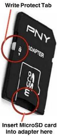
- Remove your MicroSD card from the MTCR by lightly pressing inward on the card and, when released, the card should pop out of the recorder enough to remove it.

natural_image
Close-up of a black GEATRONIC chip with metallic connectors and a red 5000 GWh label (no readable text beyond branding)- Insert the MicroSD card into the adapter.
- Slide the button on the side of the adapter to the locked position and insert the adapter (with MicroSD card inside) into your computer's memory card slot.
NOTE: The MicroSD card adapter has a write protect tab. Sliding the tab downward to the locked position prevents recording of data and protects existing data. When recording to, erasing from or formatting the MicroSD card, slide the tab upward.
- If using a Windows operating system, the computer should detect the card and assign it to a drive. Open the selected drive by clicking on the "Start" button and select "Computer" to launch Windows Explorer, the native file manager. Open the folder that was assigned to your MicroSD card.
If using a MAC operating system, the card will appear as an icon on the desktop. Double-click to open it.
- Copy the files you wish to download from the card and paste them into the selected file on your computer.
- Be sure to safely eject the card adapter when finished copying the files.
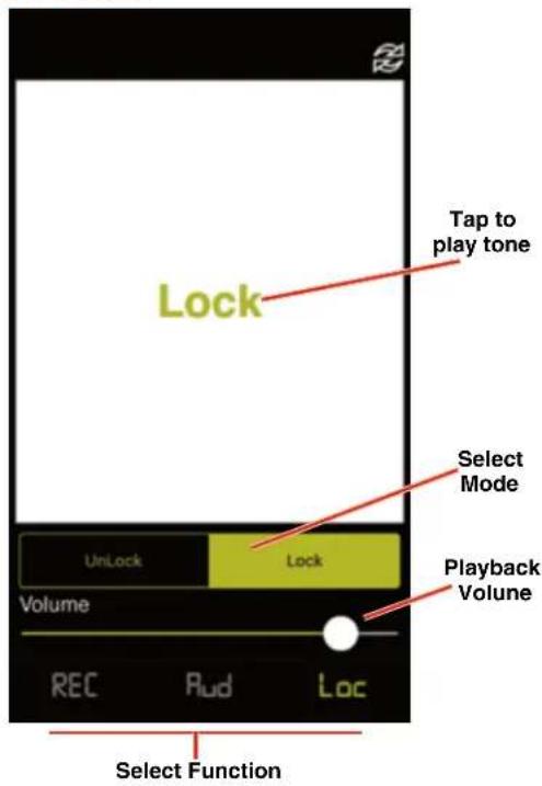
PDRRemote
By New Endian LLC
Convenient remote control is provided by a phone app available on the AppStore and Google Play. The app uses audio tones ("dweedle tones") played through the phone's speaker that are interpreted by the recorder to make changes to the recorder settings:
- Record Start/Stop
- Mic Gain Level
- Lock/Unlock
The MTCR tones are unique to the MTCR and will not react to "dweedle tones" meant for Lectrosonics transmitters.
The screens appear differently for iOS and Android phones, but perform the same functions.
For Best Results
The following conditions are required:
• The microphone must be within range.
- The recorder must be configured to enable remote control activation. See Remote on the menu.
Please be aware this app is not a Lectrosonics product. It is privately owned and operated by New Endian LLC, www.newendian.com.
iOS Version
Android Version
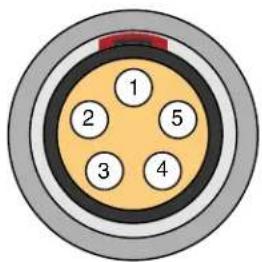
5-Pin Input Jack Wiring
The wiring diagrams included in this section represent the basic wiring necessary for the most common types of microphones and other audio inputs. Some microphones may require extra jumpers or a slight variation on the diagrams shown.
It is virtually impossible to keep completely up to date on changes that other manufacturers make to their products, thus you may encounter a microphone that differs from these instructions. If this occurs please call our toll-free number listed under Service and Repair in this manual or visit: www.lectrosonics.com/US
Audio input jack wiring:
PIN 1
Shield (ground) for positive biased electret lavaliere microphones. Shield (ground) for dynamic microphones and line level inputs.
PIN 2
Bias voltage source for positive biased electret lavaliere microphones that are not using servo bias circuitry and voltage source for 4 volt servo bias wiring.
PIN 3
Microphone level input and bias supply.
PIN 4
Bias voltage selector for Pin 3.
Pin 3 voltage depends on Pin 4 connection.
Pin 4 tied to Pin 1: 0 V
Pin 4 Open: 2 V
Pin 4 to Pin 2: 4 V
PIN 5
Line level input for tape decks, mixer outputs, musical instruments, etc.
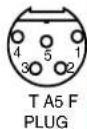
TA5F Latchlock

Insert

Insulator

Note: If you use the dust boot, remove the rubber strain relief that is attached to the TA5F cap, or the boot will not fit over the assembly.
Installing the Connector:
1) If necessary, remove the old connector from the microphone cable.
2) Slide the dust boot onto microphone cable with the large end facing the connector.
3) If necessary, slide the 1/8-inch black shrink tubing onto the microphone cable. This tubing is needed for some smaller diameter cables to ensure there is a snug fit in the dust boot.
4) Slide the backshell over the cable as shown above. Slide the insulator over the cable before soldering the wires to the pins on the insert.
5) Solder the wires and resistors to the pins on the insert according to the diagrams shown in Wiring Hookups for Different Sources. A length of .065 OD clear tubing is included if you need to insulate the resistor leads or shield wire.
6) If necessary, remove the rubber strain relief from the TA5F backshell by simply pulling it out.
7) Seat the insulator on the insert. Slide the cable clamp over the and of the insulator and crimp as shown on the next page.
8) Insert the assembled insert/insulator/clamp into the latchlock. Make sure the tab and slot align to allow the insert to fully seat in the latchlock. Thread the backshell onto the latchlock.
Microphone Cable Termination for Non-Lectrosonics Microphones
TA5F Connector Assembly

flowchart
graph LR
    A["Component 1"] --> B["Component 2"]
    B --> C["Component 3"]
    C --> D["Component 4"]
    D --> E["Component 5"]
Mic Cord Stripping Instructions

Crimping to Shield and Insulation
Strip and position the cable so that the clamp can be crimped to contact both the mic cable shield and the insulation. The shield contact reduces noise with some microphones and the insulation clamp increases ruggedness.
NOTE: This termination is intended for UHF transmitters and the MTCR only. VHF transmitters with 5-pin jacks require a different termination. Lectrosonics lavaliere microphones are terminated for compatibility with VHF and UHF transmitters, which is different from what is shown here.
Timecode Jack Wiring
The timecode connection is made via a standard LEMO 5-pin connector. Pin connections are as follows. Viewed from outside the connector.
1 - Ground
2 - SMPTE Timecode In
3 - Not used
4 - Not used
5 - Not used

natural_image
Close-up of a black plastic electronic component with two circular ports and a central metallic connector (no text or symbols visible)Wiring Hookups for Different Sources
In addition to the microphone and line level wiring hook-ups illustrated below, Lectrosonics makes a number of cables and adapters for other situations such as connecting musical instruments (guitars, bass guitars, etc.) to the transmitter. Visit www.lectrosonics.com and click on Accessories, or download the master catalog.
A lot of information regarding microphone wiring is also available in the FAQ section of the web site at:
http://www.lectrosonics.com
Hover over Support and click on FAQs. Follow the instructions to search by model number or other search options.
Compatible Wiring for Both Servo Bias Inputs and Earlier Transmitters:
Fig. 1
2 VOLT POSITIVE BIAS 2-WIRE ELECTRET


Fig. 2
4 VOLT POSITIVE BIAS 2-WIRE ELECTRET

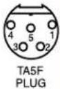
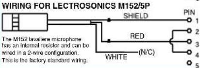
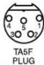
Fig. 3 - DPA Microphones
DANISH PRO AUDIO MINIATURE MODELS

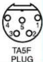
Fig. 4

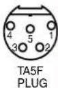
Fig. 5 - Sanken COS-11 and others
4 VOLT POSITIVE BIAS 3-WIRE ELECTRET WITH EXTERNAL RESISTOR


Fig. 6
LO-Z MICROPHONE LEVEL SIGNALS
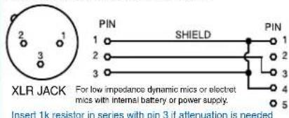
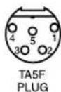
Fig. 7
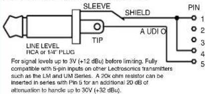
BALANCED AND FLOATING LINE LEVEL SIGNALS
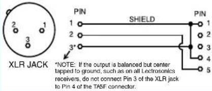
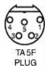
Fig. 8
UNBALANCED LINE LEVEL SIGNALS
Simple Wiring - Can ONLY be used with Servo Bias Inputs:
Servo Bias was introduced in 2005 and all transmitters with 5-pin inputs have been built with this feature since 2007.
Fig. 9


Fig. 10


Fig. 11


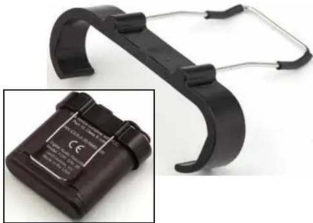
Included Accessories
55010 microSDHC memory card; Speed Class 10; UHS Speed Class 1; UHS Speed Class I

P1354 dust and moisture plug for headphone jack and timecode sync port.

natural_image
Close-up of a black plastic mechanical component with two circular ends and a curved handle (no text or symbols visible)PDRWBC wire belt clip snaps onto the housing.
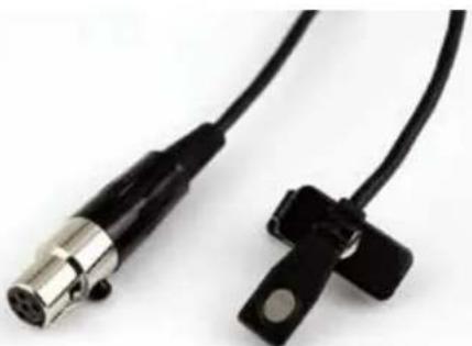
natural_image
Close-up of a black hard-coated device with attached cable, showing battery pack and label (no readable text or symbols)M152/5P electret lavaliere microphone. High-performance onmidirectional capsule; locking 5-pin plug (Switchcraft TA5F).
natural_image
Close-up of two black cable connectors with metallic connectors, no visible text or symbolsAdditional Accessories
MC35 line level adapter cable. Female XLR to female TA5F; 37 inches long. Feed line level signal to pin 5 on the TA5M jack.

natural_image
Close-up of a metallic X2B22018 audio recording device with two connectors and a coiled cable (no text or symbols visible)MC41 mic level adapter cable. Female XLR to female TA5F; 37 inches long. Feeds mic level signal to pin 3 on the TA5M jack.

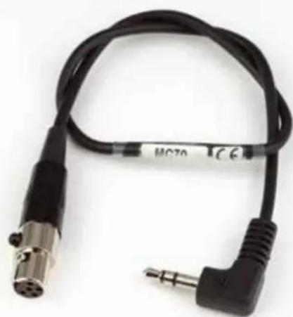
natural_image
Close-up of a metallic X-ray tube connector with green and black connectors, connected to a black cable (no visible text or symbols)MC70 line level adapter cable. Male 3.5 mm TRS to female TA5F; 14 inches long. Feeds line level signal to pin 5 on the TA5M input jack.
natural_image
Coiled black audio jack with two metallic connectors and a 3-pin connector (no visible text or symbols)Specifications
Recording
Storage media: microSDHC memory card*
File format: .wav files (BWF - Broadcast Wave File)
A/D converter: 24-bit
Sampling rate: 48 kHz
Recording modes/Bit rate: • HD mono mode: 24 bit - 144 kbytes/s
32 bit - 192 kbytes/s
- Split gain mode: 24 bit - 288 kbytes/s
32 bit - 384 kbytes/s
Input
Type: Analog mic/line level compatible;
servo bias preamp for 2V and 4V lavaliere
microphones
Input level: • Dynamic mic: 0.5 mV to 50 mV
• Electret mic: Nominal 2 mV to 300 mV
• Line level: 17 mV to 1.7 V
Input connector: TA5M 5-pin male
Headphone Jack
Connector: 3.5 mm mini jack; TRS
Maximum level: -3 dBu (575 mV RMS)
Audio Performance
Frequency response: 20 Hz to 20 kHz; +0.5/-1.5 dB
Dynamic range: 110 dB (A), before limiting
Distortion: < 0.035%
Timecode
Connector: 5-pin LEMO
Signal voltage: 0.5 Vp-p to 5Vp-p
Input impedance: 10 k Ohms
Format: SMPTE 12M - 1999 compliant
Battery Power/Life
Power consumption: 300 mW
Battery type: AAA Lithium non-rechargeable
(recommended)
AAA Lithium: 6.5 hours typical
Operating temperature range
Celsius: -20 to 50
Dimensions and Weight
Dimensions: Inches: 2.37H x 2.14W x 0.67D
Millimeters: 60H x 54W x 17D
Weight: 71 grams (2.5 ozs.) w/ AAA Lithium battery
Specifications subject to change without notice.

*microSDHC Logo is a trademark of SD-3C, LLC
Available Recording Time
Using a microSDHC memory card, the available recording times are as follows. The actual time may vary slightly from the values listed in the tables.
HD mono mode
| Size | Hrs:Min |
| 8GB | 11:12 |
| 16GB | 23:00 |
| 32GB | 46:07 |
Split gain mode
| Size | Hrs:Min |
| 8GB | 5:36 |
| 16GB | 11:30 |
| 32GB | 23:03 |
This device complies with part 15 of the FCC Rules. Operation is subject to the following two conditions: (1) This device may not cause harmful interference, and (2) this device must accept any interference received, including interference that may cause undesired operation.
NOTE: This equipment has been tested and found to comply with the limits for a Class B digital device, pursuant to part 15 of the FCC Rules. These limits are designed to provide reasonable protection against harmful interference in a residential installation. This equipment generates, uses and can radiate radio frequency energy and, if not installed and used in accordance with the instructions, may cause harmful interference to radio communications. However, there is no guarantee that interference will not occur in a particular installation. If this equipment does cause harmful interference to radio or television reception, which can be determined by turning the equipment off and on, the user is encouraged to try to correct the interference by one or more of the following measures:
—Reorient or relocate the receiving antenna.
—Increase the separation between the equipment and receiver.
—Connect the equipment into an outlet on a circuit different from that to which the receiver is connected.
—Consult the dealer or an experienced radio/TV technician for help.
Service and Repair
If your recorder malfunctions, you should attempt to correct or isolate the trouble before concluding that the equipment needs repair. Make sure you have followed the setup procedure and operating instructions and check the interconnecting cables.
We strongly recommend that you do not try to repair the equipment yourself and do not have the local repair shop attempt anything other than the simplest repair. If the repair is more complicated than a broken wire or loose connection, send the unit to the factory for repair and service. Don't attempt to adjust any controls inside the units. Once set at the factory, the various controls and trimmers do not drift with age or vibration and never require readjustment. There are no adjustments inside that will make a malfunctioning unit start working.
LECTROSONICS' Service Department is equipped and staffed to quickly repair your equipment. In warranty repairs are made at no charge in accordance with the terms of the warranty. Out-of-warranty repairs are charged at a modest flat rate plus parts and shipping. Since it takes almost as much time and effort to determine what is wrong as it does to make the repair, there is a charge for an exact quotation. We will be happy to quote approximate charges by phone for out-of-warranty repairs.
Returning Units for Repair
For timely service, please follow the steps below:
A. DO NOT return equipment to the factory for repair without first contacting us by email or by phone. We need to know the nature of the problem, the model number and the serial number of the equipment. We also need a phone number where you can be reached 8 A.M. to 4 P.M. (U.S. Mountain Standard Time).
B. After receiving your request, we will issue you a return authorization number (R.A.). This number will help speed your repair through our receiving and repair departments. The return authorization number must be clearly shown on the outside of the shipping container.
C. Pack the equipment carefully and ship to us, shipping costs prepaid. If necessary, we can provide you with the proper packing materials. UPS is usually the best way to ship the units. Heavy units should be "double-boxed" for safe transport.
D. We also strongly recommend that you insure the equipment, since we cannot be responsible for loss of or damage to equipment that you ship. Of course, we insure the equipment when we ship it back to you.
Lectrosonics USA:
Mailing address: Shipping address: Telephone:
Lectrosonics, Inc. Lectrosonics, Inc. (505) 892-4501
PO Box 15900 561 Laser Rd., Suite 102 (800) 821-1121 Toll-free
Rio Rancho, NM 87174 Rio Rancho, NM 87124 (505) 892-6243 Fax
USA USA
Web:
E-mail:
www.lectrosonics.com
sales@lectrosonics.com
Lectrosonics Canada:
Mailing Address:
Telephone:
E-mail:
720 Spadina Avenue, (416) 596-2202
Sales: sales@lectrosonics.com
Suite 600 (877) 753-2876 Toll-free Service: joeb@lectrosonics.com
Toronto, Ontario M5S 2T9 (877-7LECTRO)
(416) 596-6648 Fax
LIMITED ONE YEAR WARRANTY
The equipment is warranted for one year from date of purchase against defects in materials or workmanship provided it was purchased from an authorized dealer. This warranty does not cover equipment which has been abused or damaged by careless handling or shipping. This warranty does not apply to used or demonstrator equipment.
Should any defect develop, Lectrosonics, Inc. will, at our option, repair or replace any defective parts without charge for either parts or labor. If Lectrosonics, Inc. cannot correct the defect in your equipment, it will be replaced at no charge with a similar new item. Lectrosonics, Inc. will pay for the cost of returning your equipment to you.
This warranty applies only to items returned to Lectrosonics, Inc. or an authorized dealer, shipping costs prepaid, within one year from the date of purchase.
This Limited Warranty is governed by the laws of the State of New Mexico. It states the entire liability of Lectrosonics Inc. and the entire remedy of the purchaser for any breach of warranty as outlined above. NEITHER LECTROSONICS, INC. NOR ANYONE INVOLVED IN THE PRODUCTION OR DELIVERY OF THE EQUIPMENT SHALL BE LIABLE FOR ANY INDIRECT, SPECIAL, PUNITIVE, CONSEQUENTIAL, OR INCIDENTAL DAMAGES ARISING OUT OF THE USE OR INABILITY TO USE THIS EQUIPMENT EVEN IF LECTROSONICS, INC. HAS BEEN ADVISED OF THE POSSIBILITY OF SUCH DAMAGES. IN NO EVENT SHALL THE LIABILITY OF LECTROSONICS, INC. EXCEED THE PURCHASE PRICE OF ANY DEFECTIVE EQUIPMENT.
This warranty gives you specific legal rights. You may have additional legal rights which vary from state to state.


- Quick Start Steps
- Table of Contents
- Introduction
- Broadcast Wave Format
- Versatility
- Battery Installation
- Compatibility with microSDHC memory cards
- Installing the Card
- Formatting the SD Card
- IMPORTANT
- iXML HEADER SUPPORT
- Features and Controls
- Operating Instructions
- Powering On
- Powering Off
- Main Window
- Recording Window
- About the "Slow Card" Warning:
- Playback Window
- Timecode...
- TC Jam (jam timecode)
- Frame Rate
- Use Clock
- Mic Level
- HP Volume
- Scene & Take
- SD Card...
- Format Card
- Files/Play
- Takes/Play
- File Naming
- About Card
- Settings...
- Record Mode
- Bit Depth
- Date & Time
- Lock/Unlock
- Backlight
- Bat Type
- Remote
- About MTCR
- Default
- Firmware Updates
- In the computer:
- In the MTCR:
- Format Card?
- Recovery Process
- Copying Recordings to a Computer
- PDRRemote
- By New Endian LLC
- For Best Results
- 5-Pin Input Jack Wiring
- Audio input jack wiring:
- PIN 1
- PIN 2
- PIN 3
- PIN 4
- PIN 5
- Installing the Connector:
- Microphone Cable Termination for Non-Lectrosonics Microphones
- Timecode Jack Wiring
- Wiring Hookups for Different Sources
- Compatible Wiring for Both Servo Bias Inputs and Earlier Transmitters:
- Simple Wiring - Can ONLY be used with Servo Bias Inputs:
- Included Accessories
- Additional Accessories
- Specifications
- Recording
- Input
- Headphone Jack
- Audio Performance
- Timecode
- Battery Power/Life
- Operating temperature range
- Dimensions and Weight
- Available Recording Time
- Service and Repair
- Returning Units for Repair
- Lectrosonics USA:
- Mailing address: Shipping address: Telephone:
- Lectrosonics Canada:
- LIMITED ONE YEAR WARRANTY
Brand : Lectrosonics
Model : MTCR
Category : Audio transceiver