EMC1047 - Unknown Microchip - Free user manual and instructions
Find the device manual for free EMC1047 Microchip in PDF.

User questions about EMC1047 Microchip
0 question about this device. Answer the ones you know or ask your own.
Ask a new question about this device
Download the instructions for your Unknown in PDF format for free! Find your manual EMC1047 - Microchip and take your electronic device back in hand. On this page are published all the documents necessary for the use of your device. EMC1047 by Microchip.
USER MANUAL EMC1047 Microchip
Note the following details of the code protection feature on Microchip devices:
• Microchip products meet the specification contained in their particular Microchip Data Sheet.
- Microchip believes that its family of products is one of the most secure families of its kind on the market today, when used in the intended manner and under normal conditions.
- There are dishonest and possibly illegal methods used to breach the code protection feature. All of these methods, to our knowledge, require using the Microchip products in a manner outside the operating specifications contained in Microchip's Data Sheets. Most likely, the person doing so is engaged in theft of intellectual property.
• Microchip is willing to work with the customer who is concerned about the integrity of their code.
- Neither Microchip nor any other semiconductor manufacturer can guarantee the security of their code. Code protection does not mean that we are guaranteeing the product as "unbreakable."
Code protection is constantly evolving. We at Microchip are committed to continuously improving the code protection features of our products. Attempts to break Microchip's code protection feature may be a violation of the Digital Millennium Copyright Act. If such acts allow unauthorized access to your software or other copyrighted work, you may have a right to sue for relief under that Act.
Information contained in this publication regarding device applications and the like is provided only for your convenience and may be superseded by updates. It is your responsibility to ensure that your application meets with your specifications. MICROCHIP MAKES NO REPRESENTATIONS OR WARRANTIES OF ANY KIND WHETHER EXPRESS OR IMPLIED, WRITTEN OR ORAL, STATUTORY OR OTHERWISE, RELATED TO THE INFORMATION, INCLUDING BUT NOT LIMITED TO ITS CONDITION, QUALITY, PERFORMANCE, MERCHANTABILITY OR FITNESS FOR PURPOSE. Microchip disclaims all liability arising from this information and its use. Use of Microchip devices in life support and/or safety applications is entirely at the buyer's risk, and the buyer agrees to defend, indemnify and hold harmless Microchip from any and all damages, claims, suits, or expenses resulting from such use. No licenses are conveyed, implicitly or otherwise, under any Microchip intellectual property rights unless otherwise stated.
Microchip received ISO/TS-16949:2009 certification for its worldwide headquarters, design and wafer fabrication facilities in Chandler and Tempe, Arizona; Gresham, Oregon and design centers in California and India. The Company's quality system processes and procedures are for its PIC® MCUs and dsPIC® DSCs, KEELQQ® code hopping devices, Serial EEPROMs, microperipherals, nonvolatile memory and analog products. In addition, Microchip's quality system for the design and manufacture of development systems is ISO 9001:2000 certified.
QUALITY MANAGEMENT SYSTEM CERTIFIED BY DNV = ISO/TS 16949=
Trademarks
The Microchip name and logo, the Microchip logo, AnyRate, AVR, AVR logo, AVR Freaks, BeaconThings, BitCloud, CryptoMemory, CryptoRF, dsPIC, FlashFlex, flexPWR, Heldo, JukeBlox, KEELOQ, KEELOQ logo, Kleer, LANCheck, LINK MD, maXStylus, maXTouch, MediaLB, megaAVR, MOST, MOST logo, MPLAB, OptoLyzer, PIC, picoPower, PICSTART, PIC32 logo, Prochip Designer, QTouch, RightTouch, SAM-BA, SpyNIC, SST, SST Logo, SuperFlash, tinyAVR, UNI/O, and XMEGA are registered trademarks of Microchip Technology Incorporated in the U.S.A. and other countries.
ClockWorks, The Embedded Control Solutions Company, EtherSynch, Hyper Speed Control, HyperLight Load, IntelliMOS, mTouch, Precision Edge, and Quiet-Wire are registered trademarks of Microchip Technology Incorporated in the U.S.A.
Adjacent Key Suppression, AKS, Analog-for-the-Digital Age, Any Capacitor, AnyIn, AnyOut, BodyCom, chipKIT, chipKIT logo, CodeGuard, CryptoAuthentication, CryptoCompanion, CryptoController, dsPICDEM, dsPICDEM.net, Dynamic Average Matching, DAM, ECAN, EtherGREEN, In-Circuit Serial Programming, ICSP, Inter-Chip Connectivity, JitterBlocker, KleerNet, KleerNet logo, Mindi, MiWi, motorBench, MPASM, MPF, MPLAB Certified logo, MPLIB, MPLINK, MultiTRAK, NetDetach, Omniscient Code Generation, PICDEM, PICDEM.net, PICkit, PICtail, PureSilicon, QMatrix, RightTouch logo, REAL ICE, Ripple Blocker, SAM-ICE, Serial Quad I/O, SMART-I.S., SQI, SuperSwitcher, SuperSwitcher II, Total Endurance, TSHARC, USBCheck, VariSense, ViewSpan, WiperLock, Wireless DNA, and ZENA are trademarks of Microchip Technology Incorporated in the U.S.A. and other countries.
SQTP is a service mark of Microchip Technology Incorporated in the U.S.A.
Silicon Storage Technology is a registered trademark of Microchip Technology Inc. in other countries.
GestIC is a registered trademark of Microchip Technology Germany II GmbH & Co. KG, a subsidiary of Microchip Technology Inc., in other countries.
All other trademarks mentioned herein are property of their respective companies.
© 2018, Microchip Technology Incorporated, All Rights Reserved. ISBN: 978-1-5224-2988-3
Table of Contents
Preface 5
Chapter 1. Product Overview
1.1 Introduction ...... 9
1.2 EMC2305 Device Short Overview 9
1.3 EMC1438 Device Short Overview 9
1.4 What Is the ADM00879 Demonstration Board? 9
1.5 ADM00879 Demonstration Board Kit Contents 10
Chapter 2. Installation and Operation
2.1 Introduction ...... 11
2.2 System Requirements ...... 11
2.3 Microchip Thermal Management Utility GUI Installation 11
Chapter 3. Microchip Thermal Management Utility
3.1 Introduction ...... 15
3.2 First Launch 15
3.3 Control Toolbar 17
3.3.1 Save/Load Settings 17
3.3.2 Data Acquisition 17
3.3.3 Data Logging 17
3.3.4 Temperature Related Options 17
3.3.5 Fan Related Options 18
3.4 Demo View 19
3.4.1 Demo Options ...... 20
3.4.2 Temperature Charts 21
3.4.3 Fan Driver Tab 24
Chapter 4. Hardware Description
4.1 ADM00879 Demonstration Board Description 25
4.1.1 Fan Connection Options 26
4.1.2 PWM Fan Driver 26
4.1.3 On-Board Temperature Channels 27
4.1.4 On-Board Demonstration Heat Source and Remote Diode 27
4.1.5 External Temperature Remote Diode Connections 28
4.1.6 Optional Desktop PC Integration 28
Appendix A. Schematics and Layouts
A.1 Introduction 29
A.2 Board – Schematic – EMC2305 and EMC1438 30
A.3 Board – Schematic – Fan Driver (Fan 1) ...... 31
A.4 Board – Schematic – Fan Driver (Fan 2) ...... 31
A.5 Board – Schematic – Fan Driver (Fan 3) ...... 32
A.6 Board – Schematic – Fan Driver (Fan 4) ...... 32
A.7 Board – Schematic – Fan Driver (Fan 5) ...... 33
A.8 Board – Schematic – Interface and Power 34
A.9 Board – Schematic – Mechanical 35
A.10 Board – Top Silk 36
A.11 Board – Top Copper and Silk 36
A.12 Board – Top Copper 37
A.13 Board – Bottom Copper 37
A.14 Board – Bottom Copper and Silk 38
A.15 Board – Bottom Silk 38
Appendix B. Bill of Materials (BOM) 39
Worldwide Sales and Service 43
Preface
NOTICE TO CUSTOMERS
All documentation becomes dated, and this manual is no exception. Microchip tools and documentation are constantly evolving to meet customer needs, so some actual dialogs and/or tool descriptions may differ from those in this document. Please refer to our website (www.microchip.com) to obtain the latest documentation available.
Documents are identified with a "DS" number. This number is located on the bottom of each page, in front of the page number. The numbering convention for the DS number is "DSXXXXXXXXA", where "XXXXXXXXX" is the document number and "A" is the revision level of the document.
For the most up-to-date information on development tools, see the MPLAB ^® IDE online help. Select the Help menu, and then Topics, to open a list of available online help files.
INTRODUCTION
This chapter contains general information that will be useful to know before using the ADM00879 Fan Controller Demonstration Board. Items discussed in this chapter include:
- Document Layout
- Conventions Used in this Guide
- Warranty Registration
• Recommended Reading
• The Microchip Web Site - Customer Support
• Document Revision History
DOCUMENT LAYOUT
This document describes how to use the ADM00879 Fan Controller Demonstration Board as a development tool to emulate and debug firmware on a target board. The manual layout is as follows:
- Chapter 1. “Product Overview” – Important information about the ADM00879 Fan Controller Demonstration Board.
- Chapter 2. “Installation and Operation” – Includes instructions on installing and starting the Microchip Thermal Management Utility application.
- Chapter 3. “Microchip Thermal Management Utility”—includes instructions on operating the Thermal Management Utility.
- Chapter 4. "Hardware Description"—Contains a detailed description of the ADM00879 Fan Controller Demonstration Board
- Appendix A. “Schematic and Layouts” – Shows the schematics and layout diagrams for the ADM00879 Fan Controller Demonstration Board.
- Appendix B. "Bill of Materials (BOM)" – Lists the parts used to build the ADM00879 Fan Controller Demonstration Board.
CONVENTIONS USED IN THIS GUIDE
This manual uses the following documentation conventions:
DOCUMENTATION CONVENTIONS
| Description Represents Examples | ||
| Arial font: | ||
| Italic characters Referenced books | oks MPLAB | ^ IDE User's Guide |
| Emphasized text ...is the only compiler... | ||
| Initial caps A window the Output | window | |
| A dialog the Settings dialog | ||
| A menu selection select Enable Programmer | ||
| Quotes A field name in a window or dialog | "Save project before build" | |
| Underlined, italic text with right angle bracket | A menu path File>Save | —— |
| Bold characters A dialog button | Click OK | |
| A tab | Click the Power tab | |
| N'Rnnnn | A number in verilog format, where N is the total number of digits, R is the radix and n is a digit. | 4'b0010, 2'hF1 |
| Text in angle brackets <> | A key on the keyboard | Press,, |
| Courier New font: | ||
| Plain Courier New | Sample source code | #define START |
| Filenames | autoexec.bat | |
| File paths | c:\mcc18\h | |
| Keywords | _asm, _endasm, static | |
| Command-line options | -Opa+, -Opa- | |
| Bit values | 0, 1 | |
| Constants | 0xFF, 'A' | |
| Italic Courier New | A variable argument | file.o, where file can be any valid filename |
| Square brackets [] | Optional arguments | mccl8 [options] file [options] |
| Curly brackets and pipe character: { | } | Choice of mutually exclusive arguments; an OR selection | errorlevel {0|1} |
| Ellipses... Replaces repeated text | var_name [, | var_name...] |
| Represents code supplied by user | void main (void){ ...} | |
WARRANTY REGISTRATION
Please complete the enclosed Warranty Registration Card and mail it promptly. Sending in the Warranty Registration Card entitles users to receive new product updates. Interim software releases are available at the Microchip web site.
RECOMMENDED READING
This user's guide describes how to use the ADM00879 Fan Controller Demonstration Board. Other useful documents are listed below. The following Microchip document is available and recommended as a supplemental reference resource:
EMC1438 Data Sheet – “1°C Multiple Temperature Sensor with Hardware Controlled Standby and Hottest of Multiple Zones” (DS20005513A)
Microchip provides online support via our web site at www.microchip.com. This web site is used as a means to make files and information easily available to customers. Accessible by using your favorite Internet browser, the website contains the following information:
- Product Support – Data sheets and errata, application notes and sample programs, design resources, user's guides and hardware support documents, latest software releases and archived software
- General Technical Support – Frequently Asked Questions (FAQs), technical support requests, online discussion groups, Microchip consultant program member listing
- Business of Microchip – Product selector and ordering guides, latest Microchip press releases, listing of seminars and events, listings of Microchip sales offices, distributors and factory representatives
PRODUCT CHANGE NOTIFICATION SERVICE
Microchip's customer notification service helps keep customers current on Microchip products. Subscribers will receive e-mail notifications whenever there are changes, updates, revisions or errata related to a specified product family or development tool of interest.
To register, access the Microchip web site at www.microchip.com, click on Product Change Notification and follow the registration instructions.
CUSTOMER SUPPORT
Users of Microchip products can receive assistance through several channels:
• Distributor or Representative
- Local Sales Office
• Field Application Engineer (FAE)
- Technical Support
Customers should contact their distributor, representative or field application engineer (FAE) for support. Local sales offices are also available to help customers. A listing of sales offices and locations is included in the back of this document.
Technical support is available through the web site at: http://www.microchip.com/support.
DOCUMENT REVISION HISTORY
Revision A (May 2018)
- Initial Release of this Document.
Chapter 1. Product Overview
1.1 INTRODUCTION
This chapter provides an overview of the ADM00879 Fan Controller Demonstration Board and covers the following topics:
- EMC2305 Device Short Overview
- EMC1438 Device Short Overview
- What Is the ADM00879 Demonstration Board?
- ADM00879 Demonstration Board Kit Contents
1.2 EMC2305 DEVICE SHORT OVERVIEW
The EMC2305 device is an SMBus (System Management Bus) compliant and I ^2 C (Inter-integrated Circuit) compatible fan controller, with up to five independently controlled PWM (Pulse Width Modulation) fan drivers. Each fan driver is controlled by a programmable frequency PWM driver and FSC (Fan Speed Control) algorithm, which operates in either a closed loop fashion or as a directly PWM-controlled device.
The closed loop FSC algorithm has the capability to detect aging fans and alert the system. Likewise, it detects stalled or locked fans and triggers an interruption.
1.3 EMC1438 DEVICE SHORT OVERVIEW
The EMC1438 device is a high-accuracy, low-cost, SMBus temperature sensor ( I^2C compatible). Advanced features such as Resistance Error Correction (REC), Beta Compensation and automatic diode type detection combine to provide a robust solution for complex environmental-monitoring applications.
EMC1438 monitors up to eight temperature channels (up to seven external and one internal). The device provides ±1^ C accuracy for the internal and external diode temperatures.
1.4 WHAT IS THE ADM00879 DEMONSTRATION BOARD?
The ADM00879 Fan Controller Demonstration Board provides an example of a fan-control application, by using the EMC2305 fan controller and EMC1438 temperature sensor. There are 5 fan channels, 2 on-board temperature sensors and 6 remote temperature sensor inputs available.
The low-voltage circuits are powered from either the micro USB connector or the 2.1 mm Jack for 12V fan supply (power adapter not included), making it possible to run the PC application and set all the parameters without powering the fan drivers. Test points for the 12V input are also available.
I^2C communication is provided over USB using the on-board MCP2221 USB to I^2C bridge. The Thermal Management Utility graphic user interface (GUI) automatically detects the board and loads the appropriate interface.
An on-board heat source with 4 heat levels is provided for demonstrative purposes.
The demonstration GUI is equipped with options to manually setup all the parameters for the thermal sensor and the fan controller. The GUI also provides a fully automatic temperature control interface, where any fan channel can be linked to any temperature channel.
1.5 ADM00879 DEMONSTRATION BOARD KIT CONTENTS
The ADM00879 Demonstration Board kit includes the following:
- One ADM00879 Fan Controller Demonstration Board
- Important Information Sheet
- USB cable
- Two NPN transistors in TO-92 package to be used as remote temperature diodes.
Note: An additional power supply or bench supply is needed for powering the fans.
Chapter 2. Installation and Operation
2.1 INTRODUCTION
This section describes how to install the Microchip Thermal Management Utility GUI, required in order to interact with the ADM00879 Demonstration Board.
2.2 SYSTEM REQUIREMENTS
The ADM00879 Demonstration Board is designed to be used with a personal computer (desktop or laptop) running Microsoft ^® Windows ^® 7 or later. For USB connectivity, the minimal physical requirement for the PC is a standard type-A USB 2.0 port.
2.3 MICROCHIP THERMAL MANAGEMENT UTILITY GUI INSTALLATION
Go to www.microchip.com and search for EMC2305 or EMC1438 and download the Thermal Management Utility (version 1.5.6 or newer).
If an older version of the software is already installed, you have to remove it before installing the new one.
Follow the next steps to proceed with the installation.
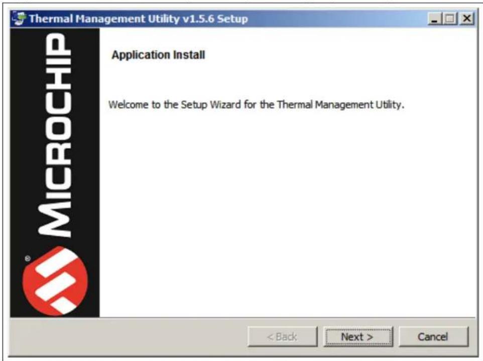
FIGURE 2-1: THERMAL MANAGEMENT UTILITY – SETUP WINDOW
text_image
Thermal Management Utility v1.5.6 Setup Application Install Welcome to the Setup Wizard for the Thermal Management Utility. < Back Next > Cancel MICROCHIPClick the Next button to continue.
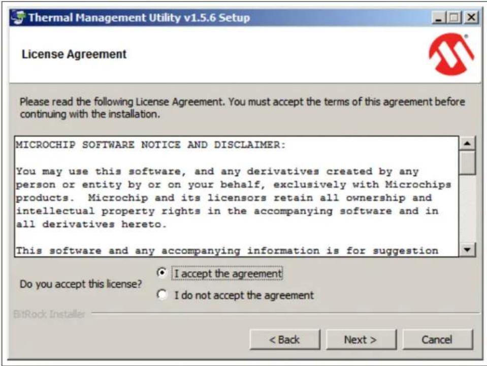
FIGURE 2-2: THERMAL MANAGEMENT UTILITY – LICENSE AGREEMENT WINDOW
text_image
Thermal Management Utility v1.5.6 Setup License Agreement Please read the following License Agreement. You must accept the terms of this agreement before continuing with the installation. MICROCHIP SOFTWARE NOTICE AND DISCLAIMER: You may use this software, and any derivatives created by any person or entity by or on your behalf, exclusively with Microchips products. Microchip and its licensors retain all ownership and intellectual property rights in the accompanying software and in all derivatives hereto. This software and any accompanying information is for suggestion Do you accept this license? ● I accept the agreement ○ I do not accept the agreement < Back Next > CancelRead and accept the License Agreement. Click the Next button to proceed.
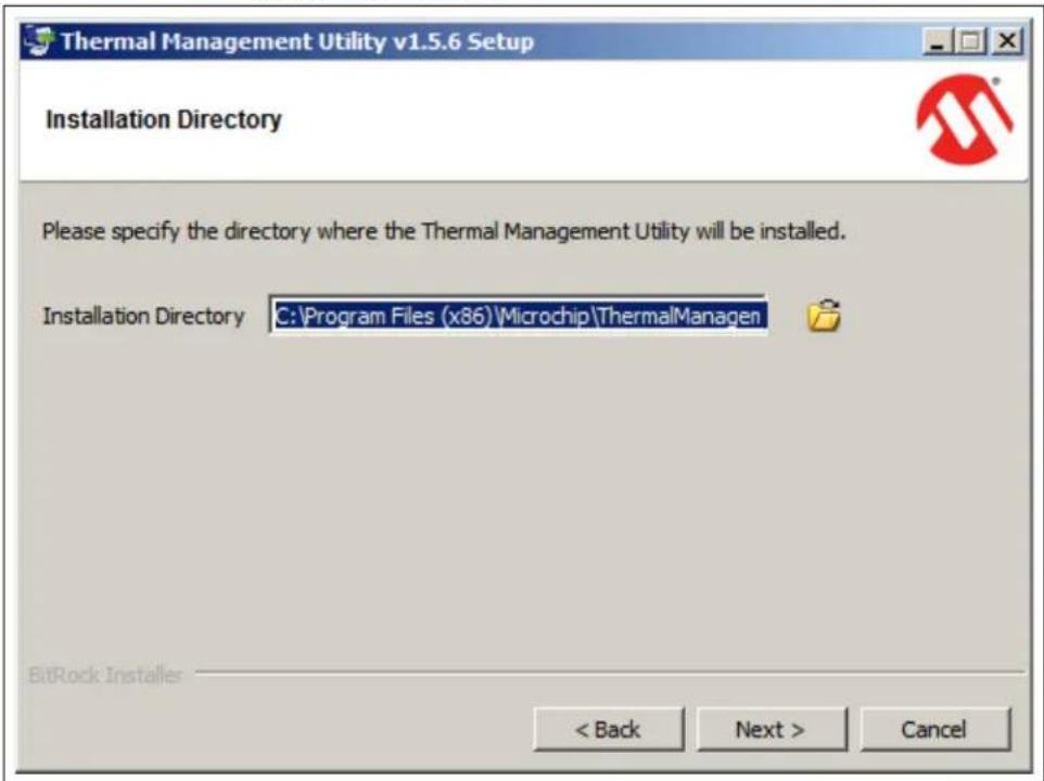
FIGURE 2-3: THERMAL MANAGEMENT UTILITY – INSTALLATION DIRECTORY WINDOW
text_image
Thermal Management Utility v1.5.6 Setup Installation Directory Please specify the directory where the Thermal Management Utility will be installed. Installation Directory C:\Program Files (x86)\Microchip\ThermalManagen BitRock Installers < Back Next > CancelChoose the desired installation directory and click Next.
FIGURE 2-4: THERMAL MANAGEMENT UTILITY – READY TO INSTALL WINDOW

text_image
Thermal Management Utility v1.5.6 Setup Ready to Install Setup is now ready to begin installing the Thermal Management Utility on your computer. BitRock Installer < Back Next > CancelOnce the installation directory has been chosen, click Next to begin the installation.
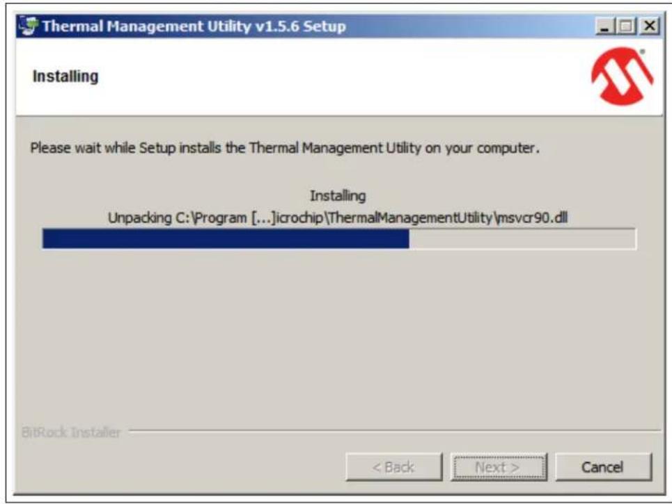
FIGURE 2-5: THERMAL MANAGEMENT UTILITY – INSTALLING WINDOW
text_image
Thermal Management Utility v1.5.6 Setup Installing Please wait while Setup installs the Thermal Management Utility on your computer. Installing Unpacking C:\Program [...]icrochip\ThermalManagementUtility\msvcr90.dll BitRock Installer < Back Next > CancelWait for the setup wizard to finish the installation.
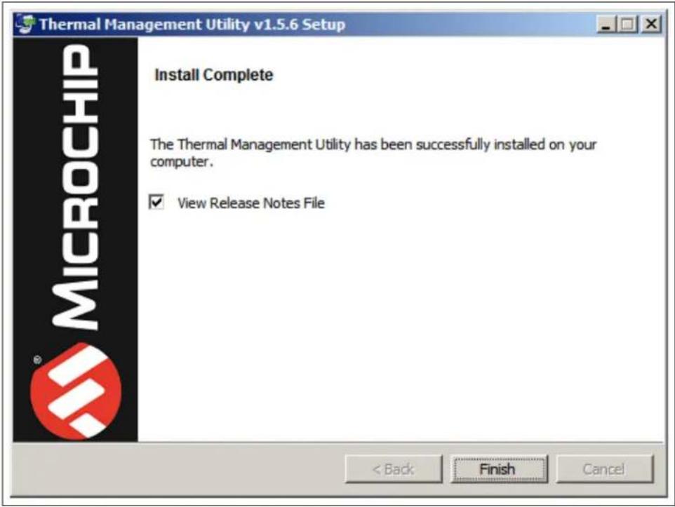
FIGURE 2-6: THERMAL MANAGEMENT UTILITY – INSTALL COMPLETE WINDOW
text_image
Thermal Management Utility v1.5.6 Setup Install Complete The Thermal Management Utility has been successfully installed on your computer. ✓ View Release Notes File < Back Finish CancelOnce the installation is completed, click Finish to exist the setup wizard.
Chapter 3. Microchip Thermal Management Utility
3.1 INTRODUCTION
The Microchip Thermal Management Utility GUI allows the user to evaluate the EMC2305 and EMC1438 devices for temperature and fan control applications.
3.2 FIRST LAUNCH
The ADM00879 Demonstration Board is required, in order to start the graphical user interface.
When the GUI is launched for the first time after the installation, or a new board is connected, it contains the fan driver and the temperature sensor currently set values. To use the Demo mode, as described in Section 3.4 "Demo View", the proper settings must be loaded. The installer automatically adds the ADM00879_Default_Settings.bin file in the C:\Users\
Once the hardware is connected, the software recognizes the device ID and displays the corresponding GUI for the ADM00879 Fan Controller Demonstration Board. When a board is connected, its fan driver and temperature sensor settings are read and displayed in the GUI.
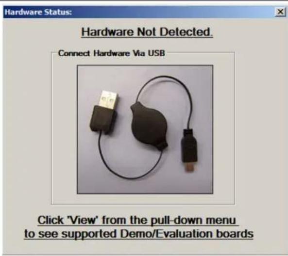
Disconnecting the USB will close the GUI and display a Hardware Not Detected dialog box, as displayed in Figure 3-1.
FIGURE 3-1: HARDWARE NOT CONNECTED DIALOG BOX
text_image
Hardware Status: Hardware Not Detected. Connect Hardware Via USB Click 'View' from the pull-down menu to see supported Demo/Evaluation boardsThe Thermal Management Utility main window (Figure 3-2) consists of a Control Toolbar (marked in Figure 3-2 with the number 1), a View Selection section (marked by the number 2), a Demo Options section (3) and a Temperature/RPM Plots section (4).
FIGURE 3-2: THERMAL MANAGEMENT UTILITY MAIN WINDOW

text_image
Thermal Management Utility - [ADM00879] View/Select GUIs One Shot Heat Source Power Dissipation 0% Detect Fan Min/Max Demo Temp Sensor (EMC1438) Fan Driver (EMC2305) 1 2 3 FAN 1 Temperature Source Ext 1 PLOT ON Operating Mode OFF FAN 2 Temperature Source Ext 1 PLOT ON Operating Mode OFF FAN 3 Temperature Source Ext 1 PLOT ON Operating Mode OFF FAN 4 Temperature Source Ext 1 PLOT ON Operating Mode OFF FAN 5 Temperature Source Ext 1 PLOT ON Operating Mode OFF FAN 1 Temperature RPU Time FAN 2 Temperature RPU Time FAN 3 Temperature RPU Time FAN 4 Temperature RPU Time FAN 5 Temperature RPU3.3 CONTROL TOOLBAR
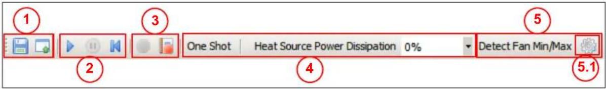
FIGURE 3-3: CONTROL TOOLBAR SECTION
text_image
1 2 3 One Shot | Heat Source Power Dissipation 0% 4 5 Detect Fan Min/Max 5.13.3.1 Save/Load Settings
The Save/Load Settings section is noted in Figure 3-3 with the number 1. This section allows the saving of all the currently configured GUI settings. The settings will be stored in a file.bin file and can be reloaded to reconfigure the board. The loading process repopulates all the available fields and writes the settings into the connected ADM00879 Demonstration Board. This process takes up to 30 seconds to complete.
3.3.2 Data Acquisition
The Data Acquisition section (noted in Figure 3-3 with the number 2) provides controls for starting, stopping and resetting the chart data.
Starting the data capture provides continuous reading of data from the temperature sensor and fan driver, updates the charts and activates the Demo View functionality. When data capture is stopped, the three demonstration modes (auto, constant and manual) are not operational.
The Reset Plot Data button clears the data from any visible chart in the currently selected view.
3.3.3 Data Logging
The Data Logging section (number 3) enables or disables the data logging. Clicking the Record Acquisition button opens a file selection window, where the destination of the log file can be set. The logs are saved as file.txt files and contain the temperature readings for all of the EMC1438's channels.
3.3.4 Temperature Related Options
The Temperature Related Options section is marked in Figure 3-3 with the number 4.
The One Shot button writes to the One Shot Register of the EMC1438's temperature sensor. This can be used to trigger an update for the temperature measurements when the device is in Standby mode. To view the measurements, click the Update Registers button from the Temp Sensor tab. In Active mode, the functionality of the One Shot button is disabled.
The Heat Source Power Dissipation controls the on-board heat source connected to channel 1 of the temperature sensor. Table 3-1 shows the approximate temperatures that can be reached when heating is enabled.
TABLE 3-1: HEAT SOURCE TEMPERATURES
| Heat % | Temperature (°C) | |
| Fan 1 – OFF Fan 1 – | 100% | |
| 0 Ambient temperature – | ||
| 25 33–33.5 | 30.5–0.75 | |
| 50 40.875–41.125 34.75–35 | ||
| 75 50–51 38.875–39.125 | ||
| 100 60–61 44.25–44.5 | ||
3.3.5 Fan Related Options
The Fan Related Options section is marked by the number 5.
The Detect Fan Min/Max button opens a dialog box (Figure 3-4), which allows the detection of the minimum and maximum RPM (Revolutions Per Minute) values for one or several connected fans. Each selected fan is initially set to the minimum drive value (configured in the Fan Driver tab, under the Min Drive percentage field), the RPM being measured subsequently. If the fan doesn't start, then the Min Drive percentage needs to be increased with the selected Accuracy step, until the fan starts. After the minimum RPM, Valid Tachometer count and minimum Drive values are determined, they are stored. In order to determine the maximum RPM value, the fan drive is set to 100% and the RPM is measured. Note that, considering that some fans reach their rated maximum speed after a longer run time, the maximum RPM value detected can be slightly lower than the fan specification.
FIGURE 3-4: DETERMINE FAN MIN/MAX RPM DIALOG BOX
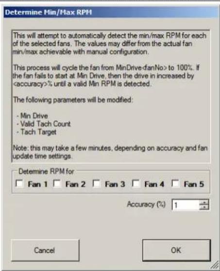
text_image
Determine Min/Max RPM This will attempt to automatically detect the min/max RPM for each of the selected fans. The values may differ from the actual fan min/max achievable with manual configuration. This process will cycle the fan from MinDrive-danNo> to 100%. If the fan fails to start at Min Drive, then the drive in increased byThe Demo RPM Offset button (marked as 5.1 in Figure 3-3) opens a dialog box (Figure 3-5), where the Min RPM offset values can be configured. This relates only to the fan control algorithm implemented in software for the demo application example. For the Auto and Constant demo modes, the algorithm uses a minimum RPM target that consists of the minimum RPM value specified in the fan configuration tab (Figure 3-15, number 6) summed with the Offset value. Due to the RPM jitter, if the fan target is set to the Min RPM value, a false fan stall detection may occur, causing the fan to be sped up unnecessarily, as the drive level used for the initial spin-up (Figure 3-15, number 5) has a minimum value of 30% (which is larger than the Min Drive setting).
This jitter is fan dependent, so each fan channel has its own offset value. The required offset value can be identified using the Fan Configuration or the Manual mode, which can drive the fan target up to the Min RPM value.
FIGURE 3-5: DEMO SETTINGS DIALOG BOX

text_image
Demo Min RPM Offset The offset will be added to the fan Min RPM target for the Auto and Constant Demo modes to avoid false fan stall detection due to RPM measurement jitter. Fan 1 100.00 Fan 2 100.00 Fan 3 100.00 Fan 4 100.00 Fan 5 100.00 Cancel OK3.4 DEMO VIEW
The Demo View section (Figure 3-6) consists of a Demo Options area (1) and a Temp/RPM Charts area (2).
FIGURE 3-6: DEMO VIEW SECTION

line
| Panel | Metric | Value | |---|---|---| | 1 | Temperature (°C) | 104 | | 1 | RPM | 7500 | | 2 | Temperature (°C) | 104 | | 2 | RPM | 7500 | | 3 | Temperature (°C) | 104 | | 3 | RPM | 7500 | | 4 | Temperature (°C) | 104 | | 4 | RPM | 7500 | | 5 | Temperature (°C) | 104 | | 5 | RPM | 7500 | | Total | Temperature (°C) | 104 | | Total | RPM | 7500 | | Total | Time | 104 | | Total | RPM | 7500 | | Total | Time | 2680 | | Total | RPM | 2680 | | Total | Time | 2680 | | Total | RPM | 2680 | | Total | Time | 2680 | | Total | RPM | 2680 | | Total | Time | 2680 | | Total | RPM | 2680 | | Total | Time | 2680 | | Total | RPM | 2680 | | Total | Time | 2683.4.1 Demo Options
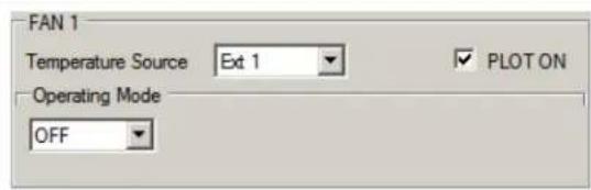
This section provides control over the operating mode of each fan and its associated temperature source.
FIGURE 3-7: DEMO OPTIONS FAN 1
text_image
FAN 1 Temperature Source Ext 1 PLOT ON Operating Mode OFF3.4.1.1 TEMPERATURE SOURCE
Each fan can be configured to monitor one of the eight available temperature channels of the EMC1438 device. The Ext1 channel is tied to the on-board heat source.
3.4.1.2 OPERATING MODE
This demonstration offers three main operating modes: Auto, Constant and Manual. The Auto and Constant modes are implemented in software by reading the temperature from the EMC1438 device and adjusting the fan speed based on this input.
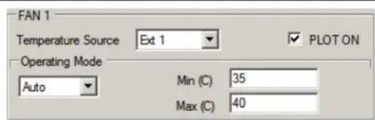
In Auto Mode, the fan speed is adjusted as follows:
- If the temperature is below the minimum temperature value, the fan is turned OFF.
- If the temperature is between the minimum and maximum values, the fan runs at the minimum RPM value summed with the Offset value.
- When the temperature exceeds the maximum value, the fan speed is adjusted, in order to keep the temperature at the maximum limit, with a hysteresis of ± 0.125^ . This outcome is dependent on the cooling solution (appropriate heat sink to dissipate the heat).
FIGURE 3-8: DEMO OPTIONS FAN 1 – AUTO MODE
text_image
FAN 1 Temperature Source Ext 1 PLOT ON Operating Mode Auto Min (C) 35 Max (C) 40In Constant Mode, the fan speed is adjusted as follows:
- If the temperature is below the target temperature value, the fan is running at the minimum RPM value summed with the Offset value.
- When the temperature exceeds the target value, the fan speed is adjusted, in order to keep the temperature at the target limit with a hysteresis of ± 0.125^ . This outcome is dependent on the cooling solution (appropriate heat sink to dissipate the heat).
FIGURE 3-9: DEMO OPTIONS FAN 1 – CONSTANT MODE

text_image
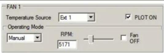
FAN 1 Temperature Source Ext 1 PLOT ON Operating Mode Constant Temperature (C) 38In Manual Mode, the fan RPM can be adjusted from minimum to maximum, by using the slider or by directly writing in the designated RPM field. The fan can be stopped by checking the Fan OFF check-box.
When setting the target to minimum RPM in Manual Mode, the fan can start to oscillate. This mode uses the driver's fan speed algorithm, so if the target is set at the minimum RPM value and the RPM goes slightly below this value (thus going over the Valid Tachometer value), a fan stall condition is detected and the driver starts to spin up the fan.
This spin-up is occurring because the minimum PWM duty cycle for the initial spin-up (or a fan stall condition) is at 30%, while the minimum rated fan speed is at 16% duty cycle. In the current demonstration configuration, this relates to a minimum fan spin-up voltage of 9.5V.
FIGURE 3-10: DEMO OPTIONS FAN 1 – MANUAL MODE
text_image
FAN 1 Temperature Source Ext 1 PLOT ON Operating Mode Manual RPM: 5171 Fan OFF3.4.2 Temperature Charts
This section displays the fan RPM and its corresponding heat source value (°C). The chart visibility can be toggled from the corresponding fan Plot On check box, located in the Demo Options section (Figure 3-6).
For a better visibility of the plotted values, a data table can be enabled from the chart's context menu. Right Click on the plot in order to trigger this menu and select the Both Graph and Table option, as displayed in Figure 3-11.
FIGURE 3-11: CHART OPTIONS
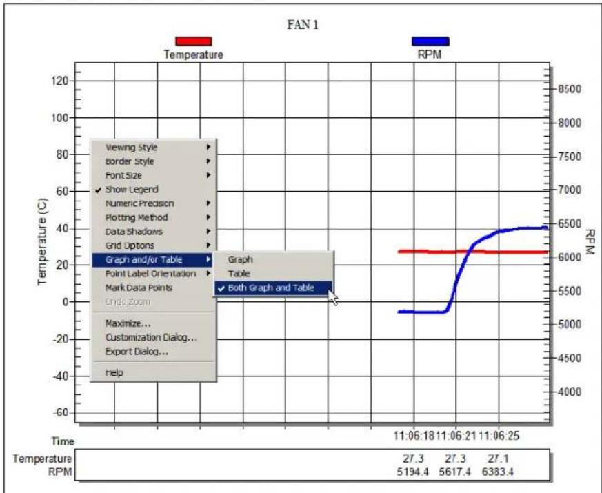
line
| Time | Temperature (°C) | RPM | | ---------- | ---------------- | ------ | | 11:06:18 | 27.3 | 5194.4 | | 11:06:21 | 27.3 | 5617.4 | | 11:06:25 | 27.1 | 6383.4 |3.4.2.1 TEMPERATURE SENSOR (EMC1438) VIEW
This view contains all values and settings related to the on-board temperature sensor.
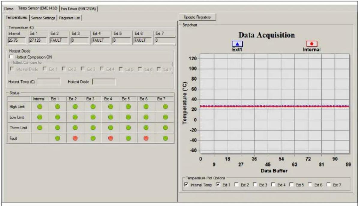
FIGURE 3-12: TEMPERATURE SENSOR VIEW – TEMPERATURES TAB
line
| Data Buffer | Temperature (°C) | |---|---| | 0 | 25.75 | | 9 | 27.125 | | 18 | 27.125 | | 27 | 27.125 | | 36 | 27.125 | | 45 | 27.125 | | 54 | 27.125 | | 63 | 27.125 | | 72 | 27.125 | | 81 | 27.125 | | 90 | 27.125 | | 99 | 27.125 | High Limit: ~-10°C, Low Limit: ~-10°C, Them Limit: ~-10°C, Fault: ~-10°C Ext1: ▲ Ext2: ▼ Ext3: □ Ext4: △ Ext5: ▶ Ext6: ▷ Ext7: ▧ Hottest Diode: □ Hottest Comparison ON: □ Hottest Compare for: □ Hottest Tempo (C): □ Hottest Diode: □ Status: Internal Ext 1 Ext 2 Ext 3 Ext 4 Ext 5 Ext 6 Ext 7 Temperature Plot Options: ✓ Internal Temp ✓ Ext 1 ✓ Ext 2 ✓ Ext 3 ✓ Ext 4 ✓ Ext 5 ✓ Ext 6 ✓ Ext 7The Temperatures tab of the Temperature Sensor View provides an overview of all the temperature related readings from the EMC1438 device:
- The temperature values are presented in both the Temperature table and in the Data Acquisition chart. The chart can be configured to display any combination of the device channels by enabling the corresponding channel check box from the Temperature Plot Options section.
- The Hottest Diode section allows turning the hottest diode detection ON or OFF and provides information about the hottest temperature and the diode it was detected on.
- The device's status is displayed in the Status section, where a green icon represents normal operation (limit not exceed, no fault condition) and a red icon signals that a limit has been reached or a fault condition has been detected.
- The device data can be read continuously, by clicking the Start button from the toolbar or manually sampled by clicking the Update Registers button. The chart is only updated during continuous sampling.
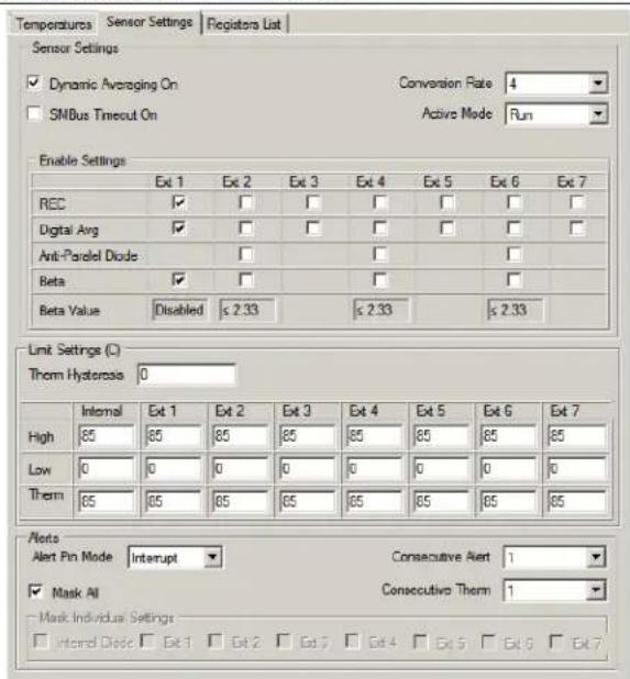
The Sensor Settings tab provides access to all of the device's settings, limit configuration and alert options.
FIGURE 3-13: SENSOR SETTINGS TAB
text_image
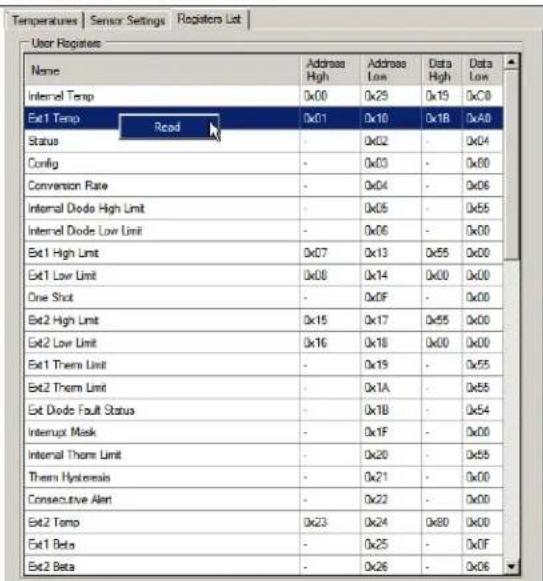
Temperatures Sensor Settings Flogisters List Sensor Settings Dynamic Averaging On Conversion Rate 4 SMBus Timeout On Active Mode Run Enable Settings Ext 1 Ext 2 Ext 3 Ext 4 Ext 5 Ext 6 Ext 7 REC ✓ ✓ ✓ ✓ ✓ ✓ ✓ ✓ Digital Avg ✓ ✓ ✓ ✓ ✓ ✓ ✓ ✓ Anti-Parallel Diode ✓ ✓ ✓ ✓ ✓ ✓ Beta ✓ ✓ ✓ ✓ ✓ ✓ Beta Value Disabled ≤ 2.33 ≤ 2.33 ≤ 2.33 Limit Settings (C) Therm Hysteresis 0 Internal Ext 1 Ext 2 Ext 3 Ext 4 Ext 5 Ext 6 Ext 7 High 85 85 85 85 85 85 85 85 Low 0 0 0 0 0 0 0 0 0 Therm 85 85 85 85 85 85 85 85 Alerts Alert Pin Mode Interrupt Consecutive Alert 1 Mask All Consecutive Therm 1 Mask Individual Settings Internal Diode Ext 1 Ext 2 Ext 3 Ext 4 Ext 5 Ext 6 Ext 7The Register List tab gives an overview of all the device registers, their addresses and their values. The values are updated continuously after the Start button is clicked or updated after clicking the Update Registers button from the EMC1438 tab. Each register can also be individually read by selecting the register and right-clicking, then selecting Read.
FIGURE 3-14: REGISTERS LIST TAB
text_image
Temperatures | Sensor Settings | Registers List | User Registers Name Address High Address Low Data High Data Low Internal Temp 0x00 0x25 0x19 0x00 Ext1 Temp Read Status - 0x02 - 0x04 Config - 0x03 - 0x00 Conversion Rate - 0x04 - 0x06 Internal Diode High Limit - 0x05 - 0x55 Internal Diode Low Limit - 0x06 - 0x00 Ext1 High Limit 0x07 0x13 0x55 0x00 Ext1 Low Limit 0x08 0x14 0x00 0x00 One Shot - 0x0F - 0x00 Ext2 High Limit 0x15 0x17 0x55 0x00 Ext2 Low Limit 0x16 0x18 0x00 0x00 Ext1 Therm Limit - 0x19 - 0x55 Ext2 Therm Limit - 0x1A - 0x55 Ext Diode Fault Status - 0x1B - 0x54 Interrupt Mask - 0x1F - 0x00 Internal Therm Limit - 0x20 - 0x55 Therm Hysteresis - 0x21 - 0x00 Consecutive Alert - 0x22 - 0x00 Ext2 Temp 0x23 0x24 0x80 0x00 Ext1 Beta - 0x25 - 0xOF Ext2 Beta - 0x26 - 0x063.4.3 Fan Driver Tab
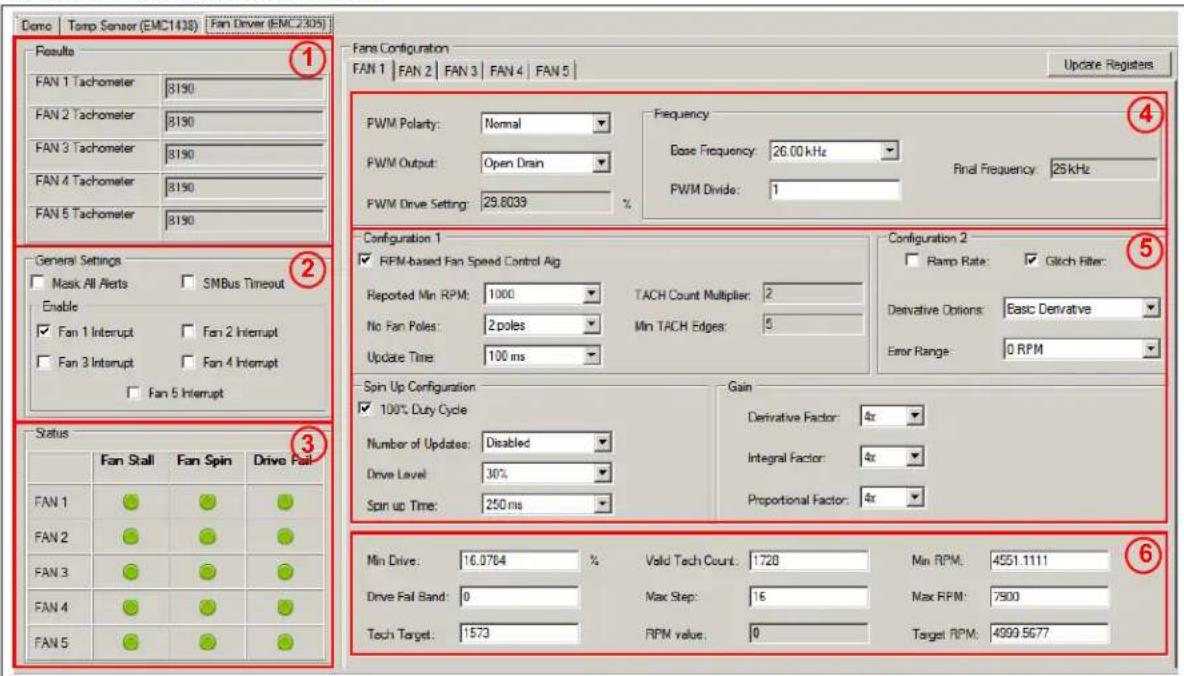
The Fan Driver tab (Figure 3-15) provides easy access to the EMC2305 device's settings and readings.
Each section of the Fan Driver tab is highlighted in Figure 3-15 by a red rectangle and a number, with each corresponding number being described below.
FIGURE 3-15: FAN DRIVER TAB
text_image
Demo | Temp Sensor (EMC1438) | Fan Driver (EMC 2/305) Results FAN 1 Tachometer | 8190 FAN 2 Tachometer | 8190 FAN 3 Tachometer | 8190 FAN 4 Tachometer | 8190 FAN 5 Tachometer | 8190 Fans Configuration FAN 1 | FAN 2 | FAN 3 | FAN 4 | FAN 5 | Update Registers FWM Polarity: Normal FWM Output: Open Drain FWM Drive Setting: 29.6039 % Frequency Base Frequency: 26.00 kHz Final Frequency: 25 kHz PWM Divide: 1 Configuration 1 ✓ RPM-based Fan Speed Control Alg Reported Min RPM: 1000 TACH Count Multiplier: 2 No Fan Poles: 2 poles Min TACH Edges: 5 Update Time: 100 ms Configuration 2 ☐ Ramp Rate: ✓ Glitch Filter: Derivative Options: Basic Derivative Error Range: 0 RPM Spin Up Configuration ✓ 100% Duty Cycle Number of Updates: Disabled Drive Level: 30% Spin up Time: 250 ms Gain Derivative Factor: 4x Integral Factor: 4x Proportional Factor: 4x Min Drive: 16.0764 % Valid Tech Count: 1728 Min RPM: 4551.1111 Drive Fail Band: 0 Max Step: 16 Max RPM: 7500 Tech Target: 1573 RPM value: 0 Target RPM: 4999.5677 Status Fan Stall Fan Spin Drive Fail FAN 1 ● ● ● FAN 2 ● ● ● FAN 3 ● ● ● FAN 4 ● ● ● FAN 5 ● ● ●- The Fan Tachometer Results section shows the last read values of the tachometer for all fan driver channels.
- The General Settings section allows toggling the alert settings and the SMBus timeout.
- The Status table displays the status of the fan driver: a green icon indicates normal operation and a red icon indicates a flagged fan event.
- The PWM Settings section contains all PWM related settings for the selected fan driver channel.
- The General Configuration section gives access to the rest of the driver's settings.
- The Fan Related Settings section contains the drive and RPM/Tach options needed to properly drive the connected fan. The Min RPM field is connected to the Valid Tach Count field; if either value is changed, the other is updated as well. The same is true for the Target RPM field and the Tach Target field. The RPM value represents the read RPM value of the fan.
Chapter 4. Hardware Description
4.1 ADM00879 DEMONSTRATION BOARD DESCRIPTION
The printed circuit board form factor is compatible with a PCI (Peripheral Component Interconnect) card slot in a desktop PC. With the addition of a PCI bracket and an IDE (Integrated Drive Electronics) connector (J7 - not populated), the board can be mounted inside a desktop PC case. The J10 connector footprint is compatible with an on-board USB connector.
Power for this board can come from four sources. The 2.1 mm jack (J8) is used to power the board during normal operation with 12V, while the micro USB connector (J9) is used for powering the low-voltage digital circuits, in case the 12V supply is missing. There are also two test points (TP1 and TP2) available that are connected in parallel with the jack, for a direct connection to a lab power supply. The IDE connector J7 (not populated) can also be used to draw 12V to the board.
The maximum voltage supported on the jack and the power test point connections is 16V, limited by the 3.3V regulator that is powering the low voltage circuits.
The communication with the PC is provided through the MCP2221 device, an USB to I^2C bridge.
There are five fan channels available, each with its own switch mode PWM driver and 6 remote diode channels accessible through J1, J2 and J3 connector blocks. All five fan driver channels are symmetrical and share the same designators on the silkscreen.
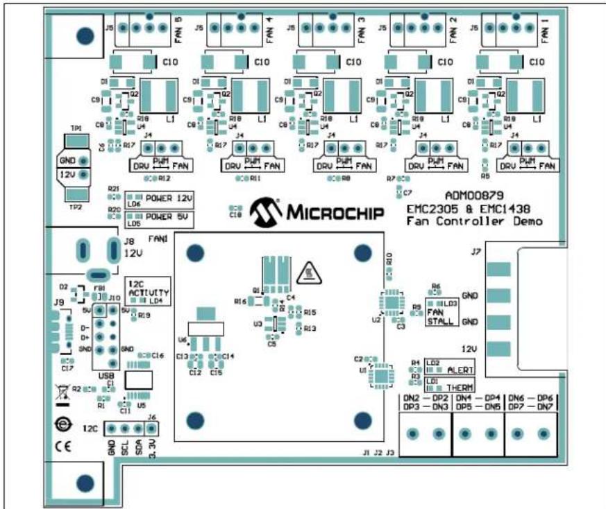
FIGURE 4-1: ADM00879 DEMONSTRATION BOARD TOP VIEW

text_image
MICROCHIP AQM00879 ENC250S & ENC1438 Fast Controller Demo4.1.1 Fan Connection Options
The fan connectors are compatible with both 3-wire and 4-wire fans. Below each fan driver is a 3-pin jumper that connects the PWM output from the EMC2305 fan controller to the fan driver circuit (DRV) or the PWM input of the 4-wire fan (FAN).
If no jumper selection is made, the fan driver provides an unregulated 12V output.
4.1.2 PWM Fan Driver
All five fan driver channels use an efficient high side DC/DC drive topology that maintains the GND connection for the fan tachometer output.
FIGURE 4-2: PWM FAN DRIVER

text_image
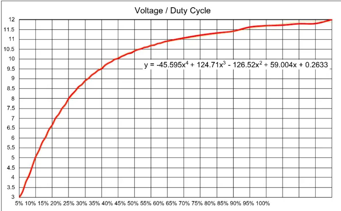
+12V PWM 3 2 4 5 1 +12V 2 3 TACH GND GND GND GNDThe output voltage versus the PWM duty cycle for the fan provided in the kit is characterized in Figure 4-3.
FIGURE 4-3: PWM DUTY CYCLE TO VOLTAGE CORRESPONDENCE
line
| Duty Cycle | Voltage | | ---------- | ------- | | 5% | 3.0 | | 10% | 4.5 | | 15% | 6.0 | | 20% | 7.0 | | 25% | 8.0 | | 30% | 8.5 | | 35% | 9.0 | | 40% | 9.5 | | 45% | 10.0 | | 50% | 10.5 | | 55% | 10.8 | | 60% | 11.0 | | 65% | 11.2 | | 70% | 11.3 | | 75% | 11.4 | | 80% | 11.5 | | 85% | 11.6 | | 90% | 11.7 | | 95% | 11.8 | | 100% | 11.9 |Considering that the minimum specified voltage for the provided fan is 7V, the minimum drive setting needs to be set at 16%, in order to ensure a reliable fan operation and tachometer reading.
This minimum drive setting and Voltage per Duty cycle behavior is dependent on the drawn current and varies from fan to fan. Figure 4-3 is provided only for reference on how this particular driver and fan combination behaves and to help with understanding the relationship between the output voltage and the PWM duty cycle.
It can be noticed that, by setting the PWM duty cycle at 50%, the fan RPM won't be set at 50%. This is where the EMC2305 RPM-based Fan Speed Control Algorithm solves the problem, by automatically adjusting the PWM duty cycle to achieve a target RPM.
4.1.3 On-Board Temperature Channels
Two out of the 8 temperature channels of the EMC1438 device are connected on fixed sensors on the ADM00879 Demonstration Board:
- The internal temperature channel inside the EMC1438 (U1)
- The demonstration heat source and remote diode transistor Q1.
4.1.4 On-Board Demonstration Heat Source and Remote Diode
The Q1 dual NPN transistor is used both as a heat source and as a remote diode, in order to help provide an out-of-the-box demonstration of the implemented PID (proportional-integral-derivative) controller in the Thermal Management Utility GUI.
FIGURE 4-4: HEAT SOURCE SCHEMATIC

text_image
PWM_HEAT R13 0603 100k 1% C4 0.1uF 25V 0603 GND R15 2.2k 0603 1% GND U3 MCP6001 +3.3V GND R14 100R 0603 1% +12V 7.8 Q1A Q1B PHPT610030NKX 1 5.6 1 4 DP1 3 DN1 R16 1R 1206 1% GND4.1.5 External Temperature Remote Diode Connections
There are 6 remote-temperature channels accessible through three terminal blocks, each connector being able to support two anti-parallel diodes.
FIGURE 4-5: REMOTE DIODE CONNECTION DIAGRAM

text_image
External Diode Pair y x to DPx / DNy to DNy / DPx Anti-parallel diodes using discrete NPN transistors4.1.6 Optional Desktop PC Integration
The board has the necessary form factor to fit into a PCI slot inside a desktop PC. The mounting bracket and PC connectors are not included but are listed in the bill of materials (BOM) for reference.
Appendix A. Schematics and Layouts
A.1 INTRODUCTION
This appendix contains the following schematics and layouts for ADM00879 Demonstration Board:
- Board – Schematic – EMC2305 and EMC1438
- Board – Schematic – Fan Driver (Fan 1)
- Board – Schematic – Fan Driver (Fan 2)
- Board – Schematic – Fan Driver (Fan 3)
- Board – Schematic – Fan Driver (Fan 4)
- Board – Schematic – Fan Driver (Fan 5)
- Board – Schematic – Interface and Power
- Board – Schematic – Mechanical
- Board – Top Silk
- Board – Top Copper and Silk
- Board – Top Copper
- Board – Bottom Copper
- Board – Bottom Copper and Silk
- Board – Bottom Silk
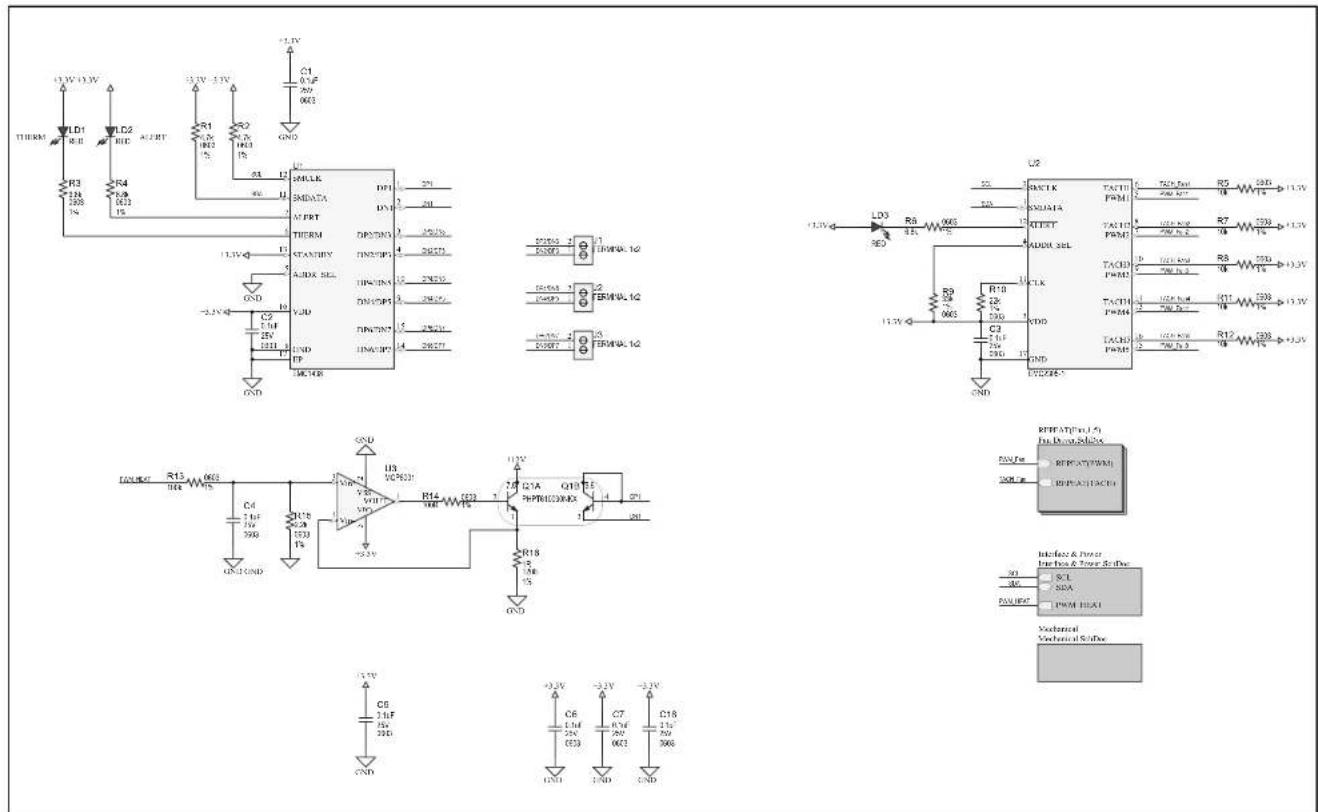
A.2 BOARD - SCHEMATIC - EMC2305 AND EMC1438
text_image
1.3V 1.3V LD1 R8 LD2 HD AC/RT R1 IN2 IN3 IN4 GND R3 IN 200 IN R4 IN 200 IN +2.5V +3.5V +3.5V +3.5V +3.5V +3.5V +3.5V +3.5V +3.5V +3.5V +3.5V +3.5V +3.5V +3.5V +3.5V +3.5V +3.5V +3.5VA.3 BOARD - SCHEMATIC - FAN DRIVER (FAN 1)
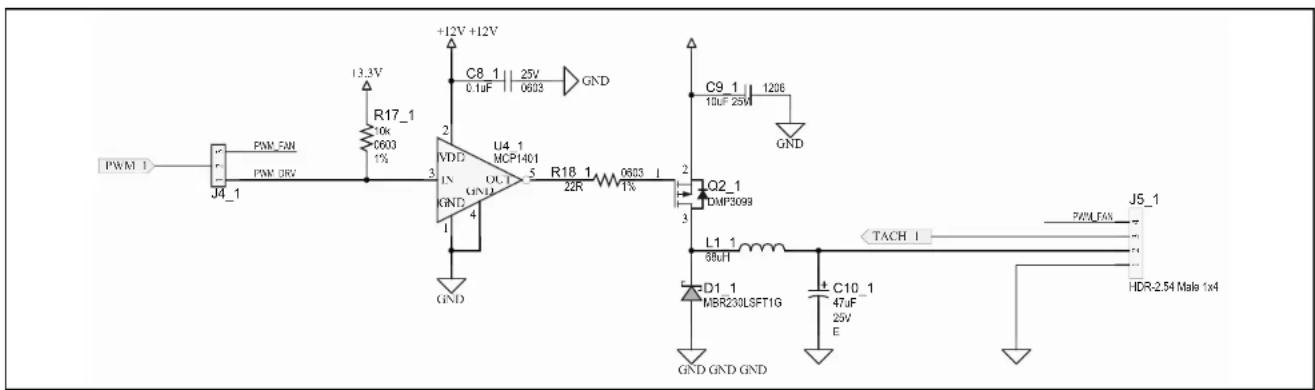
text_image
PWM 1 J4_1 PWM 5W PWM 0V R17_1 10k 0603 1% +12V +12V C8_1 0.1uF 25V 0603 GND U4_1 MCP1401 VDI3 IN GND UCL 5 R18_1 22R 0603 1% GND C9_1 10uF 25W 1206 GND Q2_1 DMP3099 L1_1 88uH TACH I J5_1 PWM FAN 7 74 74 D1_1 MBR230LSFT1G C10_1 47uF 25V E HDR-2.54 Male 1x4 GND GND GNDA.4 BOARD - SCHEMATIC - FAN DRIVER (FAN 2)
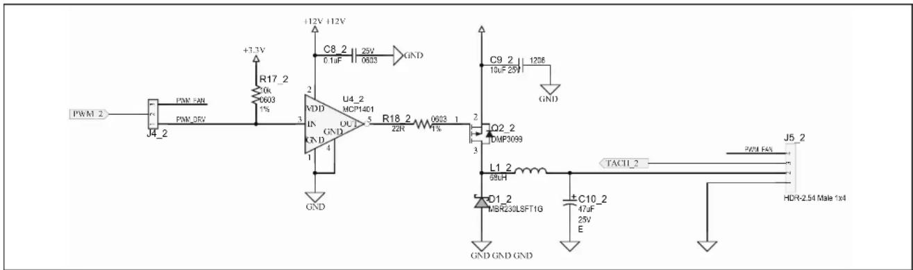
text_image
PWM 2 +3.3V R17_2 0k 6003 1% J4_2 PWM 50R PWM 0RV +12V +12V C8_2 0.1uF 25V 0603 GND U4_2 MCP1401 IN GND GND R18_2 22R 0603 1% Q2_2 DMP3099 L1_2 68uH TACT1_2 C10_2 47uF 25V E GND GND GND C9_2 10uF 25V 1206 GND J5_2 PWM F4% HDR-2.54 Male 1x4A.5 BOARD - SCHEMATIC - FAN DRIVER (FAN 3)

text_image
PWM 3 PWM FAN PWM DRV R17_3 10k 0603 1% +12V +12V C8_3 0.1uF 25V 0603 GND U4_3 MCP1401 UDD IN GND GND R18_3 22R 0603 1% GND Q2_3 DMP3099 L1_3 88uH TACH 3 J5_3 PWM FAN HDR-2.54 Male 1x4 C10_3 47uF 25V E GND GND GNDA.6 BOARD - SCHEMATIC - FAN DRIVER (FAN 4)

text_image
PWM 4 J4_4 PWM F4% PWM DRV +3.3V R17_4 0k 600 1% 2 VDD U4_4 MCP1401 OUT 5 GND GND GND +12V +12V C8 4 3.1uF 25V 6053 GND C9 4 10uF 25V 1206 GND Q2_4 DMP3099 L1_4 58uH TACI1_4 J5_4 PWM F4% HDR-2.54 Male 1x4 D1_4 MBR230LSFT1G C10_4 47uF 25V E GND GND GNDA.7 BOARD - SCHEMATIC - FAN DRIVER (FAN 5)

text_image
PWM_5 J4_5 PNM_5IN PNM_0RV 13.3V R17_5 10k 0603 1% +12V +12V C8_5 25V 0.1uF 0603 GND U4_5 MCP1401 NVDL IN GND R18_5 22R 0603 1% 4 GND C9_5 1206 10uF 25V GND Q2_5 DMP3089 L1_5 58uH TACH_5 J5_5 PWLJAN D1_5 MBR230LSFT1G C10_5 47uF 25V E GND GND GND HDR-2.54 Male 1x4A.8 BOARD - SCHEMATIC - INTERFACE AND POWER
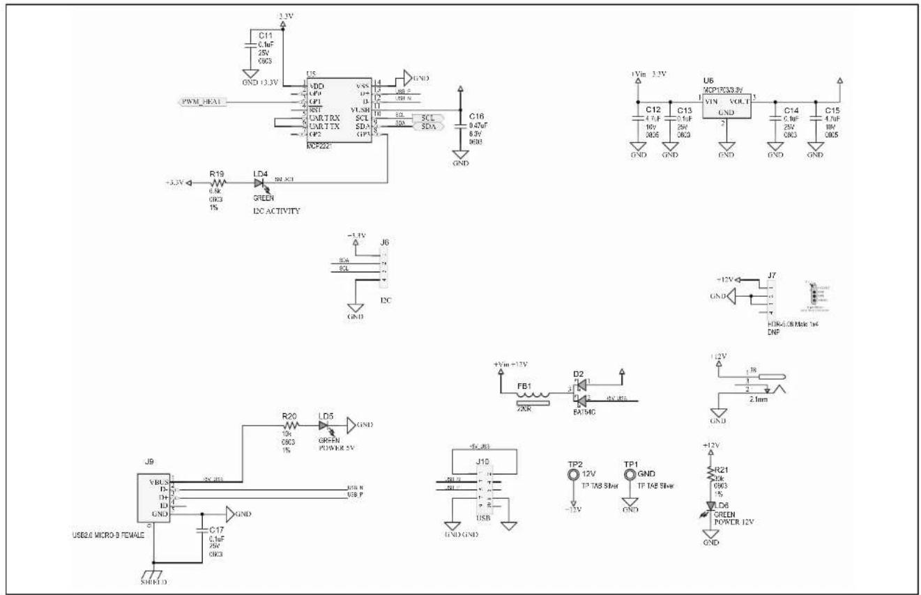
text_image
C11 0.1uF 25V 0k3 GND +3.3V PWM-HEA1 U5 NDD CP0 GP1 RST CARTRX CARTTX GP2 LDP222 +3.3V R19 0.8k 0k3 1% LD4 50Ω XCL GREEN DC ACTIVITY J6 SCL I2C GND +Vin +13V FB1 20kR D2 BATHG +Vin +13V +Vin 3.3V C12 4.0F 10V 20kS C13 0.1uF 25V 0k3 VIN VOLT GND C14 6.1uF 25V 0k3 C15 4.7uF 10V 0k5 GND J7 HOR-5.0B Make 1x4 DNF +12V J10 USB2.6 MICRO-B FEMALE C17 0.1uF 25V 0k3 GND +12V R21 2kK 0k3 1% LED6 GREEN POWER 12V GNDA.9 BOARD - SCHEMATIC - MECHANICAL
FAN1

FAN 40x10mm 3 Wire
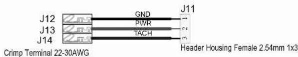
text_image
J12 GND J11 J13 PWR J14 TACH Header Housing Female 2.54mm 1x3 Crimp Terminal 22-30AWGPAD1

RUBBER PAD D9.4 H4.8
SCR1

Screw M3x16mm Nylon
SCR2

Screw M3x16mm Nylon
SCR3

Screw M3x16mm Nylon
SCR4

Screw M3x16mm Nylon
PAD2

RUBBER PAD D9.4 H4.8
STANDOFF1

Standoff M3 Nylon 10mm
STANDOFF2

Standoff M3 Nylon 10mm
STANDOFF3

Standoff M3 Nylon 10mm
STANDOFF4

Standoff M3 Nylon 10mm
PAD3

RUBBER PAD D9.4 H4.8
NUT1

Nut M3 Nylon
NUT2

Nut M3 Nylon
NUT3

Nut M3 Nylon
NUT4

Nut M3 Nylon
PAD4

RUBBER PAD D9.4 H4.8
CBL1
USB Male-A to Male Micro-B
JP1

Shunt 2.54mm 1x2 Handle

JP5

BRACKET1

PCI Bracket DNP
SCR5

DNP
Phillips Screw 1/4"
SCR6

DNP
LABEL1

Label Need Help Large
Example of remote diodes using NPN transistors


A.10 BOARD - TOP SILK
natural_image
Pure electrical circuit lines without any symbolsA.13 BOARD - BOTTOM COPPER
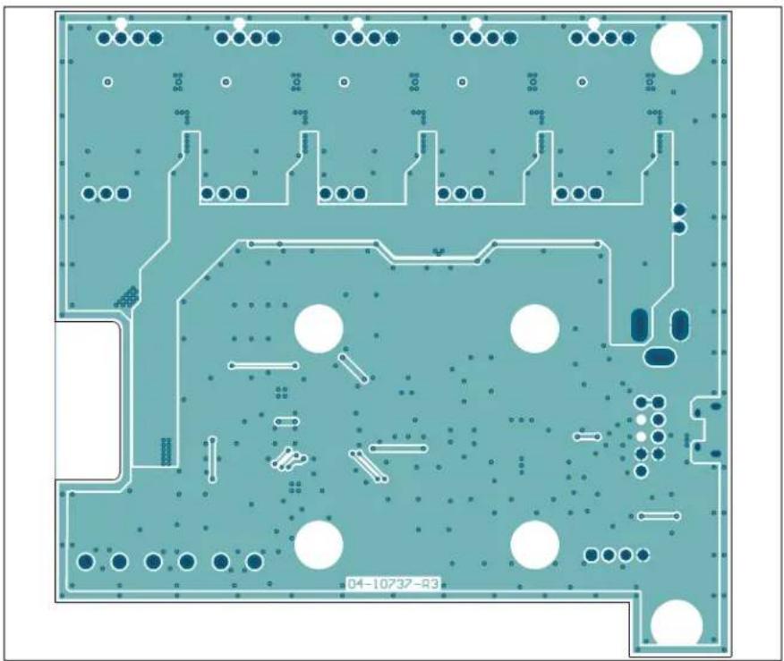
natural_image
Top-down view of a printed circuit board with various electronic components and traces (no readable text or symbols)A.14 BOARD - BOTTOM COPPER AND SILK

natural_image
Top-down view of a printed circuit board with various electronic components and traces (no readable text or symbols)A.15 BOARD - BOTTOM SILK

natural_image
Floor plan layout with scattered circular and dot patterns, no text or symbols presentAppendix B. Bill of Materials (BOM)
TABLE B-1: ADM00879 DEMONSTRATION BOARD BILL OF MATERIALS
| Qty. | Reference Description M | Manufacturer Part Number | ||
| 17 C1, | C2, C3, C4, C5, C6,C7, C8_Fan1, C8_-Fan2, C8_Fan3, C8_-Fan4, C8_Fan5, C11,C13, C14, C17, C18 | Capacitor, Ceramic, 0.1 μF,25V, 10%, X7R, SMD, 0603 | TDK Corporation C1608X | 7R1E104K080AA |
| 5 C10_Fan1, C10_Fan2,C10_Fan3, C10_Fan4,C10_Fan5 | Capacitor, Tantalum, 47 μF,25V, 10%, 0.6R, SMD, E | Vishay Sprague 293D476 | X9025E2TE3 | |
| 2 | C12, C15 | Capacitor, Ceramic, 4.7 μF,10V, 10%, X5R, SMD, 0805 | Panasonic®- ECG | ECJ-GVB1A475M |
| 1 | C16 | Capacitor, Ceramic, 0.47 μF,6.3V, 10%, X5R, SMD, 0603 | Murata ElectronicsNorth America, Inc. | GRM188R60J474KA01D |
| 5 C9_Fan1, C9_Fan2,C9_Fan3, C9_Fan4,C9_Fan5 | Capacitor, Ceramic, 10 μF,25V, 10%, X7R, SMD, 1206 | Taiyo Yuden Co., Ltd. | TMK316B7106KL-TD | |
| 5 D1_Fan1, D1_Fan2,D1_Fan3, D1_Fan4,D1_Fan5 | Diode, Schottky, 430 mV,2A, 30V, SMD, SOD-123FL | ON Semiconductor® | MBR230LSFT1G | |
| 1 D2 | Diode | Schottky, 530 mV,200 mA, 30V, SOT-23-3 | Diodes Incorporated® | BAT54CTA |
| 1 FB1 | Ferrite | 2A, 220R SMD,0805 | Murata ElectronicsNorth America, Inc. | BLM21PG221SN1D |
| 3 J1, J2, J3 | Connector Terminal, 5 mm,1x2, Female, 12-26AWG,18A, TH, R/A | PHOENIX CONTACT | 1935161 | |
| 5 J4_Fan1, J4_Fan2,J4_Fan3, J4_Fan4,J4_Fan5 | Connector, HDR-2.54, Male,1x3, Gold, 5.84 MH, TH,VERT | FCI | 68000-103HLF | |
| 5 J5_Fan1, J5_Fan2,J5_Fan3, J5_Fan4,J5_Fan5 | Connector, HDR-2.54, Male,1x4, Tin, Lock, 7.49 MH, TH,VERT | Molex® ConnectorCorporation | 0470531000 | |
| 1 J6 | Connector, HDR-2.54, Male,1x4, Gold, 5.84 MH, TH,VERT | Wurth Elektronik | 61300411121 | |
| 1 J8 | Connector, Power, 2.1 mm,5.5 mm, Switch, Slotted, TH,R/A | MPD – MemoryProtection Devices, Inc. | EJ508A | |
| 1 J9 | Connector, USB 2.0MICRO-B, Female,TH/SMD, R/A | FCI | 10118194-0001LF | |
| Qty. | Reference | Description | Manufacturer | Part Number |
| 5 L1_Fan1, L1_Fan2,L1_Fan3, L1_Fan4,L1_Fan5 | Inductor, 68 μH, 0.95A,20%, SMD, L6W6H4.5 | Taiyo Yuden Co., Ltd. NRS6045T680MMGK | ||
| 3 LD1, | LD2, LD3 Diode, LED, Red | ed, 2V,20 mA, 250 mcd, Clear,SMD, 0603 | Wurth Elektronik 150060RS75000 | |
| 3 LD4, | LD5, LD6 Diode, LED, Green | en, 3.2V,20 mA, 430 mcd, Clear,SMD, 0603 | Wurth Elektronik 150060GS75000 | |
| 1 PCB1 | ADM00879 Demonstration Board - Printed Circuit Board | MicrochipTechnology Inc. | 04-10737-R3 | |
| 1 Q1 Transistor, BJT, Dual, | NPN+NPN, 100V, 3A,1.25W, LFPAK56D-8 | Nexperia USA Inc. PHPT610030NKX | ||
| 5 Q2_Fan1, Q2_Fan2,Q2_Fan3, Q2_Fan4,Q2_Fan5 | Transistor, FET, P-CH, -30V,-3.8A, 1.08W, SOT-23-3 | Diodes Incorporated® | DMP3099L-7 | |
| 2 | R1, R2 | Resistor, TKF, 4.7 kΩ, 1%,1/10W, SMD, 0603 | Panasonic® - ECG ERJ-3EKF4701V | |
| 1 R10 Resistor, TKF, 22 kΩ, 1%, | 1/10W, SMD, 0603 | Panasonic® - ECG ERJ-3EKF2202V | ||
| 1 R13 Resistor, TKF, 100 kΩ, 1%, | 1/10W, SMD, 0603 | Panasonic® - ECG ERJ-3EKF1003V | ||
| 1 R14 Resistor, TKF, 100R, 1%, | 1/10W, SMD, 0603 | Panasonic® - ECG ERJ-3EKF1000V | ||
| 1 R15 Resistor, TKF, 2.2kΩ, 1%, | 1/10W, SMD, 0603 | Panasonic® - ECG ERJ-3EKF2201V | ||
| 1 R16 Resistor, TKF, 1R, 1%, | 1/4W, SMD, 1206 | Yageo Corporation RC1206FR-071RL | ||
| 5 R18_Fan1, R18_Fan2,R18_Fan3, R18_Fan4,R18_Fan5 | Resistor, TKF, 22R, 1%,1/10W, SMD, 0603 | Panasonic® - ECG ERJ-3EKF22R0V | ||
| 1 R21 Resistor, TKF, 30 kΩ, 1%, | 1/10W, SMD, 0603 | StackpoleElectronics, Inc. | RMCF0603FT30K0 | |
| 4 | R3, R4, R6, R19 | Resistor, TKF, 6.8 kΩ, 1%,1/10W, SMD, 0603 | Panasonic® - ECG ERJ-3EKF6801V | |
| 11 R5, | R7, R8, R11, R12,R17_Fan1, R17_Fan2,R17_Fan3, R17_Fan4,R17_Fan5, R20 | Resistor, TKF, 10 kΩ, 1%,1/10W, SMD, 0603 | Panasonic® - ECG ERJ-3EKF1002V | |
| 1 | R9 | Resistor, TKF, 33 kΩ, 1%,1/10W, SMD, 0603 | Panasonic® - ECG ERJ-3EKF3302V | |
| 4 STANDOFF1, STAND-OFF2, STANDOFF3,STANDOFF4 | Mechanical, HW, Stand-off,M3x10 mm, M/F, HEX,Nylon | Essentra Components | NTS-10 | |
| 2 TP1, | TP2 Connector, TP, TAB, Silver,Mini, 3.8 x 2.03, SMD | KeystoneElectronics Corp. | 5019 | |
| 1 U1 M | CHP Analog Temperature | Sensor, -40°C to +125°C, EMC1438-2-AP-TR, QFN-16 | Microchip Technology inc. | EMC1438-2-AP-TR |
| 1 U2 M | CHP Analog Fan Control- | ler, 5-Channel EMC2305-1-AP-TR, QFN-16 | Microchip Technology Inc. | EMC2305-1-AP-TR |
| 1 U3 M | CHP Analog OPAMP | 1-Channel, 1 MHz MCP6001T-I/OT, SOT-23-5 | Microchip Technology Inc. | MCP6001T-I/OT |
| 5 U4_F | Fan1, U4_Fan2, U4_Fan3, U4_Fan4, U4_Fan5 | MCHP Analog Fet Driver, Single-Inverting, MCP1401T-E/OT, SOT-23-5 | Microchip Technology Inc. | MCP1401T-E/OT |
| 1 U5 M | CHP Interface USB I | ^2C UART MCP2221-I/ST, TSSOP-14 | Microchip Technology Inc. | MCP2221-I/ST |
| 1 U6 M | CHP Analog LDO, 3.3V, | MCP1703T-3302E/DB, SOT-223-3 | Microchip Technology Inc. | MCP1703T-3302E/DB |
Note 1: The components listed in this Bill of Materials are representative of the PCB assembly. The released BOM used in manufacturing uses all RoHS-compliant components.
TABLE B-2: BILL OF MATERIALS – MECHANICAL PARTS
| Qty. | Reference Description | Manufacturer Part Number | ||
| 1 CBL | Mechanical, HW | Cable, USB Male-A to Male Micro-B, Clear 4 | DongGuan ZanXin A006ZX021 | |
| 1 FAN | Mechanical, HW | Fan, 12VDC, 40 x 10 mm, 8000 RPM, Tachometer 3, Wire | Delta Electronics, Inc. | ASB0412VHA-AF00 |
| 1 J11 | Mechanical, HW | Connector Header Housing, Female, 2.54 mm 1x3 | Molex® Connector Corporation | 22-01-3037 |
| 3 J12, | J13, J14 Mechanical, HW, CRIMP, Terminal, Female, 22-30AWG, Tin | Molex® Connector Corporation | 0008500113 | |
| 5 JP1 | JP2, JP3, JP4, JP5 | Mechanical, HW, Jumper, 2.54 mm, 1x2, Handle, Gold | TE Connectivity, Ltd. | 881545-2 |
| 1 LABEL1 | LABEL | — | — | |
| 4 NUT | NUT2, NUT3, NUT4 | Mechanical, HW, NUT, M3, Nylon | Keystone Electronics Corp. | 4688 |
| 4 | PAD1, PAD2, PAD3, PAD4 | Mechanical, HW, Rubber Pad, Cylindrical, D9.4, H4.8, Clear | Multicomp Inc. | 2565 |
| 2 Q3, | Q4 Transistor, BJT, NPN, 40V, 0.2A, 0.625W, TO-92-3 | Fairchild Semiconductor® | 2N3904TA | |
| 4 SCR | SCR2, SCR3, SCR4 | Mechanical, HW, Screw, M3 x 16 mm, Pan, Slotted, Nylon | Keystone Electronics Corp. | 29346 |
Note 1: The components listed in this Bill of Materials are representative of the PCB assembly. The released BOM used in manufacturing uses all RoHS-compliant components.
TABLE B-3: BILL OF MATERIALS – DO NOT POPULATE PARTS
| Qty. | Reference Description | Manufacturer Part Number | ||
| 1 | BRACKET1 Mechanical, HW, Bracket, PCI Keystone | Electronics Corp. | 9203-1 | |
| 1 | J7 Connector, HDR-5.08, Male, 1x4, Tin, 7.49 MH, SMD | Molex Connector Corporation | 0015244455 | |
| 1 | J10 Connector, HDR-2.54, Male, 2x5 0.100" (2.54 mm), TH, VERT | Samtec, Inc. TSW-105-07-G-D | ||
| 2 | SCR5, SCR6 Machine Screw Pan, Phillips, 4-40 Keystone | Electronics Corp. | 9900 | |
Note 1: The components listed in this Bill of Materials are representative of the PCB assembly. The released BOM used in manufacturing uses all RoHS-compliant components.
Worldwide Sales and Service
AMERICAS
Corporate Office
2355 West Chandler Blvd.
Chandler, AZ 85224-6199
Tel: 480-792-7200
Fax: 480-792-7277
Technical Support:
http://www.microchip.com/
support
Web Address:
www.microchip.com
Atlanta
Duluth, GA
Tel: 678-957-9614
Fax: 678-957-1455
Austin, TX
Tel: 512-257-3370
Boston
Westborough, MA
Tel: 774-760-0087
Fax: 774-760-0088
Chicago
Itasca, IL
Tel: 630-285-0071
Fax: 630-285-0075
Dallas
Addison, TX
Tel: 972-818-7423
Fax: 972-818-2924
Detroit
Novi, MI
Tel: 248-848-4000
Houston, TX
Tel: 281-894-5983
Indianapolis
Noblesville, IN
Tel: 317-773-8323
Fax: 317-773-5453
Tel: 317-536-2380
Los Angeles
Mission Viejo, CA
Tel: 949-462-9523
Fax: 949-462-9608
Tel: 951-273-7800
Raleigh, NC
Tel: 919-844-7510
New York, NY
Tel: 631-435-6000
San Jose, CA
Tel: 408-735-9110
Tel: 408-436-4270
Canada - Toronto
Tel: 905-695-1980
Fax: 905-695-2078
ASIA/PACIFIC
Australia - Sydney
Tel: 61-2-9868-6733
China - Beijing
Tel: 86-10-8569-7000
China - Chengdu
Tel: 86-28-8665-5511
China - Chongqing
Tel: 86-23-8980-9588
China - Dongguan
Tel: 86-769-8702-9880
China - Guangzhou
Tel: 86-20-8755-8029
China - Hangzhou
Tel: 86-571-8792-8115
China - Hong Kong SAR
Tel: 852-2943-5100
China - Nanjing
Tel: 86-25-8473-2460
China - Qingdao
Tel: 86-532-8502-7355
China - Shanghai
Tel: 86-21-3326-8000
China - Shenyang
Tel: 86-24-2334-2829
China - Shenzhen
Tel: 86-755-8864-2200
China - Suzhou
Tel: 86-186-6233-1526
China - Wuhan
Tel: 86-27-5980-5300
China - Xian
Tel: 86-29-8833-7252
China - Xiamen
Tel: 86-592-2388138
China - Zhuhai
Tel: 86-756-3210040
ASIA/PACIFIC
India - Bangalore
Tel: 91-80-3090-4444
India - New Delhi
Tel: 91-11-4160-8631
India - Pune
Tel: 91-20-4121-0141
Japan - Osaka
Tel: 81-6-6152-7160
Japan - Tokyo
Tel: 81-3-6880-3770
Korea - Daegu
Tel: 82-53-744-4301
Korea - Seoul
Tel: 82-2-554-7200
Malaysia - Kuala Lumpur
Tel: 60-3-7651-7906
Malaysia - Penang
Tel: 60-4-227-8870
Philippines - Manila
Tel: 63-2-634-9065
Singapore
Tel: 65-6334-8870
Taiwan - Hsin Chu
Tel: 886-3-577-8366
Taiwan - Kaohsiung
Tel: 886-7-213-7830
Taiwan - Taipei
Tel: 886-2-2508-8600
Thailand - Bangkok
Tel: 66-2-694-1351
Tel: 43-7242-2244-39
Fax: 43-7242-2244-393
Denmark - Copenhagen
Tel: 45-4450-2828
Fax: 45-4485-2829
Finland - Espoo
Tel: 358-9-4520-820
France - Paris
Tel: 33-1-69-53-63-20
Fax: 33-1-69-30-90-79
Germany - Garching
Tel: 49-8931-9700
Germany - Haan
Tel: 49-2129-3766400
Germany - Heilbronn
Tel: 49-7131-67-3636
Germany - Karlsruhe
Tel: 49-721-625370
Germany - Munich
Tel: 49-89-627-144-0
Fax: 49-89-627-144-44
Germany - Rosenheim
Tel: 49-8031-354-560
Israel - Ra'anana
Tel: 972-9-744-7705
Italy - Milan
Tel: 39-0331-742611
Fax: 39-0331-466781
Italy - Padova
Tel: 39-049-7625286
Netherlands - Drunen
Tel: 31-416-690399
Fax: 31-416-690340
Norway - Trondheim
Tel: 47-7289-7561
Poland - Warsaw
Tel: 48-22-3325737
Romania - Bucharest
Tel: 40-21-407-87-50
Spain - Madrid
Tel: 34-91-708-08-90
Fax: 34-91-708-08-91
Sweden - Gothenberg
Tel: 46-31-704-60-40
Sweden - Stockholm
Tel: 46-8-5090-4654
UK - Wokingham
Tel: 44-118-921-5800
Fax: 44-118-921-5820