Rack E3C252D4ID-2T - Server ASROCK - Free user manual and instructions
Find the device manual for free Rack E3C252D4ID-2T ASROCK in PDF.

User questions about Rack E3C252D4ID-2T ASROCK
0 question about this device. Answer the ones you know or ask your own.
Ask a new question about this device
Download the instructions for your Server in PDF format for free! Find your manual Rack E3C252D4ID-2T - ASROCK and take your electronic device back in hand. On this page are published all the documents necessary for the use of your device. Rack E3C252D4ID-2T by ASROCK.
USER MANUAL Rack E3C252D4ID-2T ASROCK
Baseboard Management Controller
USER GUIDE
AST2500, Rev. 1.06
Copyright © 2022 ASRock Rack Inc.
All Rights Reserved.
Contents
1.0 Introduction....10
2.0 BMC Web User Interface Service 11
2.1 BMC WebUI Login URL....11
2.1.1 Configuring BMC IP Address by UEFI BIOS 11
2.1.1.1 Obtain BMC IP Address from DHCP mode 11
2.1.1.2 Setting Static BMC IP Address through UEFI BIOS 14
2.2 Username and Password....15
2.3 Accessing BMC WebUI Service....17
2.3.1 Menu Bar 18
2.3.2 Quick Link and User Information 20
2.3.2.2 User Information 21
2.4 Dashboard....22
2.4.1 Power-On Hours....23
2.4.2 Pending Deassertions 23
2.4.3 Access Log 23
2.4.4 Product Information....23
2.4.5 Firmware Information....23
2.4.6 Network Information 23
2.4.7 Today and 30 Days....24
2.4.8 Sensor Monitoring 24
2.5 Sensor 25
2.5.1 Sensor Detail 26
2.6 System Information 27
2.6.1 System Inventory....28
2.6.1.1 Processor 29
2.6.1.2 Memory Controller 30
2.6.1.3 PCIE Device 31
2.6.1.4 PCIE Function 32
2.6.1.5 Storage 33
2.6.2 FRU Information 35
2.6.2.1 Chassis Information....36
2.6.2.2 Board Information 36
2.6.2.3 Product Information 36
2.6.3 Power Source 38
2.6.4 SMBIOS Information 40
2.7 Logs & Reports 41
2.7.1 IPMI Event Log 42
2.7.2 System Log....44
2.7.3 Audit Log 45
2.7.4 Video Log 46
2.7.5 Post Code 48
2.7.6 Debug Log....49
2.8 Settings 50
2.8.1 Captured BSOD 52
2.8.2 Date & Time....53
2.8.3 External User Services 55
2.8.3.1 LDAP/E-Directory Settings 56
2.8.3.1.1 General LDAP/E-Directory Settings 57
2.8.3.1.2 Role Groups 59
2.8.3.2 Active Directory Settings 61
2.8.3.2.1 General Active Directory Settings 62
2.8.3.2.2 Role Groups 64
2.8.3.3 RADIUS Settings 66
2.8.3.3.1 General RADIUS Settings 67
2.8.3.3.2 Advanced RADIUS Settings 68
2.8.4 KVM Mouse Setting....69
2.8.5 Log Settings....70
2.8.5.1 SEL Log Settings Policy 71
2.8.5.2 Advanced Log Settings 72
2.8.6 Media Redirection 74
2.8.6.1 General Settings....75
2.8.6.2 VMedia Instance Settings....77
2.8.6.3 Remote Session 78
2.8.6.4 Active Redirections....80
2.8.7 Network Settings....81
2.8.7.1 Network IP Settings....82
2.8.7.2 Network Bond Configuration 84
2.8.7.3 DNS Configuration....85
2.8.8 PAM Order Settings....88
2.8.9 Platform Event Filters 89
2.8.9.1 Event Filters 90
2.8.9.2 Alert Policies....94
2.8.9.3 LAN Destinations....96
2.8.10 Services....98
2.8.11 SMTP Settings 101
2.8.12 SSL Settings 103
2.8.12.1 View SSL Certificate 104
2.8.12.2 Generate SSL Certificate....106
2.8.12.3 Upload SSL Certificate 108
2.8.13 System Firewall....109
2.8.13.1 General Firewall Settings....110
2.8.13.1.1 Existing Firewall Settings....111
2.8.13.1.2 Add Firewall Settings....113
2.8.13.2 IP Firewall Rules....115
2.8.13.2.1 Existing IP Rules.... 116
2.8.13.2.2 Add New IP Rule 118
2.8.13.3 Port Firewall Rules....119
2.8.13.3.1 Existing Port Rules 120
2.8.13.3.2 Add New Port Rule....122
2.8.14 User Management 124
2.8.15 Video Recording....128
2.8.15.1 Auto Video Settings.... 129
2.8.15.1.1 Video Trigger Settings.... 130
2.8.15.1.2 Video Remote Storage....132
2.8.15.1.3 Pre-Event Video Recordings 134
2.8.16 IPMI Interfaces 135
2.8.17 Keep Share NIC Link Up 136
2.8.18 FAN Settings....137
2.8.18.1 Open Loop Control Table 138
2.8.18.2 Close Loop Control Table....140
2.8.18.3 Temperature Sensor and Corresponding Fan Table 142
2.8.18.4 FAN Mode....144
2.8.19 Power Restore Policy 146
2.8.20 Password Settings....147
2.9 Remote Control....149
2.9.1 H5Viewer....150
2.9.2 JViewer 156
2.10 Image Redirection.... 165
2.10.1 Remote Images....166
2.11 Power Control 168
2.12 Miscellaneous....169
2.12.1 UID Control 170
2.12.2 Post Snoop 171
2.13 Maintenance 172
2.13.1 Backup Configuration 173
2.13.2 Firmware Image Location 174
2.13.3 Firmware Update....175
2.13.4 BIOS Update....176
2.13.6 FPGA Update 179
2.13.7 Retimer Update 180
2.13.8 Backplane Update....181
2.13.9 CPLD Update....182
2.13.10 Preserve Configuration....183
2.13.11 Restore Configuration 185
2.13.12 Restore Factory Defaults 186
2.13.13 Reset....188
2.14 Sign Out....189
3.0 OEM IPMI Commands 190
3.1 Supported OEM IPMI Commands 190
3.1.1 0x52 - Master Write Read .... 191
3.1.2 0x67 - Get Boot Complete....191
3.1.3 0x82 - Set Sensor Monitor .... 191
3.1.4 0x83 - Get Sensor Monitor....191
4.0 LED Indicator....192
4.1 BMC Heartbeat LED....192
4.2 UID LED 192
4.3 System Fault LED 193
4.4 FAN Fault LED 193
Figures
Figure 1. Snapshot of BMC Network Configuration Page ...... 12
Figure 2. Snapshot of BMC IP Address Shown in Screen During UEFI BIOS POST....13
Figure 3. Snapshot of BIOS LOGO Screen with BMC IP Address....13
Figure 4. Snapshot of Configure BMC Static IP Address....14
Figure 5. Snapshot of BMC WebUI Service Login Page....15
Figure 6. Snapshot of BMC WebUI Service Main Page ...... 17
Figure 7. Snapshot of Menu Bar ...... 18
Figure 8. Snapshot of Quick Link and User Information....20
Figure 9. Snapshot of User Information and Popup Window....21
Figure 10. Snapshot of Dashboard Page 22
Figure 11. Snapshot of Sensor Reading Page 25
Figure 12. Snapshot of Sensor Detail Page 26
Figure 13. Snapshot of System Information Page....27
Figure 14. Snapshot of System Inventory Page 29
Figure 15. Snapshot of Memory Controller Page....30
Figure 16. Snapshot of PCIE Device Page ...... 31
Figure 17. Snapshot of PCIE Function Page....32
Figure 18. Snapshot of Storage Page....33
Figure 19. Snapshot of FRU Information Page....35
Figure 20. Snapshot of Power Source Page ...... 38
Figure 21. Snapshot of SMBIOS Information Page 40
Figure 22. Snapshot of IPMI Event Log Page 42
Figure 23. Snapshot of System Log Page 44
Figure 24. Snapshot of Audit Log Page 45
Figure 25. Snapshot of Video Log Page 46
Figure 26. Snapshot of Post Code Page 48
Figure 27. Snapshot of Debug Log Page....49
Figure 28. Snapshot of Settings Page....51
Figure 29. Snapshot of BSOD Page....52
Figure 30. Snapshot of Date & Time Page....53
Figure 31. Snapshot of External User Services Page 55
Figure 32. Snapshot of LDAP/E-Directory Settings Page....56
Figure 33. Snapshot of General LDAP/E-Directory Settings Page ....57
Figure 34. Snapshot of Role Groups Slots....59
Figure 35. Snapshot of Add Role Groups Page 59
Figure 36. Snapshot of Active Directory Settings Page....61
Figure 37. Snapshot of General Active Directory Settings Page 62
Figure 38. Snapshot of Role Groups Slots....64
Figure 39. Snapshot of Add Role Groups Page 64
Figure 40. Snapshot of RADIUS Settings Page....66
Figure 41. Snapshot of General RADIUS Settings Page ...... 67
Figure 42. Snapshot of Advanced RADIUS Settings Page....68
Figure 43. Snapshot of KVM Mouse Setting Page 69
Figure 44. Snapshot of Log Settings Page 70
Figure 45. Snapshot of SEL Log Settings Policy Page....71
Figure 46. Snapshot of Advanced Log Settings Page....72
Figure 47. Snapshot of Media Redirection Page....74
Figure 48. Snapshot of General Settings Page....75
Figure 49. Snapshot of VMedia Instance Settings Page 77
Figure 50. Snapshot of Remote Session Page....78
Figure 51. Snapshot of Active Redirections Page 80
Figure 52. Snapshot of Network Settings Page....81
Figure 53. Snapshot of Network IP Settings Page 82
Figure 54. Snapshot of Network Bond Configuration Page....84
Figure 55. Snapshot of DNS Configuration Page....85
Figure 56. Snapshot of PAM Order Settings Page....88
Figure 57. Snapshot of Platform Event Filters Page....89
Figure 58. Snapshot of Platform Event Filters Slot List Page 90
Figure 59. Snapshot of Event Filters Configuration Page....91
Figure 60. Snapshot of Alert Policies Page....94
Figure 61. Snapshot of Alert Policies Configuration Page 95
Figure 62. Snapshot of LAN Destinations Page....96
Figure 63. Snapshot of LAN Destinations Configuration Page 97
Figure 64. Snapshot of Services Page....98
Figure 65. Snapshot of Services Configuration Page....99
Figure 66. Snapshot of Services Sessions Page....100
Figure 67. Snapshot of SMTP Settings Page 101
Figure 68. Snapshot of SSL Settings Page 103
Figure 69. Snapshot of View SSL Certificate Page 104
Figure 70. Snapshot of Generate SSL Certificate Page....106
Figure 71. Snapshot of Upload SSL Certificate Page....108
Figure 72. Snapshot of System Firewall Page....109
Figure 73. Snapshot of General Firewall Settings Page 110
Figure 74. Snapshot of Existing Firewall Settings Page of General Firewall Settings....111
Figure 75. Snapshot of Existing Firewall Settings Instance Page of General Firewall Settings 111
Figure 76. Snapshot of Add Firewall Settings page of General Firewall Settings....113
Figure 77. Snapshot of IP Firewall Rules Page 115
Figure 78. Snapshot of Existing IP Rules Page 116
Figure 79. Snapshot of Existing IP Rules Instance Page of IP Firewall Rules....116
Figure 80. Snapshot of Add IP Rules Instance Page of IP Firewall Rules....118
Figure 81. Snapshot of Port Firewall Rules Page 119
Figure 82. Snapshot of Existing Port Rules Page 120
Figure 83. Snapshot of Existing Port Rules Instance Page of Port Firewall Rules....120
Figure 84. Snapshot of Add Port Rules Instance Page of Port Firewall Rules 122
Figure 85. Snapshot of User Management Page....124
Figure 86. Snapshot of User Management Configuration Page ...... 125
Figure 87. Snapshot of Video Recording Page....128
Figure 88. Snapshot of Auto Video Recording Page 129
Figure 89. Snapshot of Video Trigger Settings Page....130
Figure 90. Snapshot of Video Remote Storage Page....132
Figure 91. Snapshot of Pre-Event Video Recordings Page 134
Figure 92. Snapshot of IPMI Interfaces Page....135
Figure 93. Snapshot of Keep Share NIC Link Up Page 136
Figure 94. Snapshot of FAN Settings Page ...... 137
Figure 95. Snapshot of Open Loop Control Table Page....138
Figure 96. Snapshot of Close Loop Control Table Page....140
Figure 97. Snapshot of Temperature Sensor and Corresponding Fan Table Page....142
Figure 98. Snapshot of FAN Mode Page....144
Figure 99. Snapshot of Power Restore Policy Page....146
Figure 100. Snapshot of Password Settings Page....147
Figure 101. Snapshot of Remote Control Page....149
Figure 102. Snapshot of H5Viewer KVM Page....150
Figure 103. Snapshot of JViewer KVM Application....156
Figure 104. Snapshot of Virtual Media Application....160
Figure 105. Snapshot of Video Record Window....162
Figure 106. Snapshot of Image Redirection Page....165
Figure 107. Snapshot of Remote Images Page 166
Figure 108. Snapshot of Power Control Page....168
Figure 109. Snapshot of Miscellaneous Page ...... 169
Figure 110. Snapshot of UID Control Page 170
Figure 111. Snapshot of Post Snoop Page 171
Figure 112. Snapshot of Maintenance Page 172
Figure 113. Snapshot of Backup Configuration Page....173
Figure 114. Snapshot of Firmware Image Location Page ...... 174
Figure 115. Snapshot of Firmware Update Page 175
Figure 116. Snapshot of BIOS Update Page....176
Figure 117. Snapshot of PSU Update Page 178
Figure 118. Snapshot of FPGA Update Page 179
Figure 119. Snapshot of Retimer Update Page....180
Figure 120. Snapshot of Backplane Update Page ...... 181
Figure 121. Snapshot of CPLD Update Page....182
Figure 122. Snapshot of Preserve Configuration Page 183
Figure 123. Snapshot of Restore Configuration Page....185
Figure 124. Snapshot of Restore Factory Defaults Page 186
Figure 125. Snapshot of Reset Page....188
Figure 126. Snapshot of Sign Out Button on the Current User Window....189
Tables
Table 1. BMC Heartbeat LED Status ...... 192
Table 2. UID LED Status....192
Table 3. System Fault LED Status....193
Table 4. FAN Fault LED Status....194
Revision History
| Revision | Description | Date |
| 1.06 | ● Add LED Indicator description. | September 2022 |
| 1.05 | ● Restructure document. | May 2022 |
1.0 Introduction
This user guide is written for system administrators and end-users who intend to configure the Intelligence Platform Management Interface (IPMI) settings supported by ASPEED AST2500 Baseboard Management Controller (BMC), which is integrated into the mainboard. This document provides detailed information on configuring the BMC settings supported by the AST2500 controller.
Note: All screenshots in this document are provided for illustrative purposes only and may vary from the actual product.
2.0 BMC Web User Interface Service
The BMC firmware provides an embedded web server that allows users to configure the BMC settings through the BMC Web User Interface (WebUI) service. The detailed information is listed in the following sections.
2.1 BMC WebUI Login URL
BMC WebUI service supports login the service by URL with either HyperText Transfer Protocol (HTTP) or HyperText Transfer Protocol Secure (HTTPS) methods. For security reasons, it is recommended that users use HTTPS to access the BMC WebUI service.
2.1.1 Configuring BMC IP Address by UEFI BIOS
To access the BMC WebUI service by URL, users can configure or obtain the BMC IP address from UEFI BIOS.
2.1.1.1 Obtain BMC IP Address from DHCP mode
- Boot to UEFI BIOS SETUP page.
- Select the Server Mgmt page.
- Select the BMC Network Configuration page.
4. Obtain BMC IP Address from the field of Station IP Address if Configuration address source is set to DHCP or
Figure 1. Snapshot of BMC Network Configuration Page

text_image
Aptio Setup Utility - Copyright (C) 2022 American Megatrends, Inc. Server Mgmt BMC Network Configuration BMC Out of band Access [No Change] Out of band Access Enabled ************************** Configure IPV4 support ************************** Lan channel (Failover) Manual setting IPMI LAN [No] Configuration address source DHCP Station IP address 192.168.36.108 Current subnet mask 255.255.254.0 Current MAC address DO-50-99-F1-A4-BF Current router IP address 192.168.36.1 VLAN [Disabled] ************************** Configure IPV6 support ************************** Lan channel 1 IPV6 Support [Enabled] Manual setting IPMI LAN(IPV6) [No Change] Configuration Address source DHCP When "Manual Setting IPMI LAN Configuration" is set to default "No", the IP address will follow DHCP. If you would like to set it as Static IP, please toggle the settings to "Yes", and the changes for IPMI LAN configuration will take place after rebooting. +: Select Screen ↑↓: Select Item Enter: Select +/-: Change Option F1: General Help F7: Discard Changes F9: Load UEFI Defaults F10: Save and Exit ESC: Exit Version 2.20.1275, Copyright (C) 2022 American Megatrends, Inc.- Obtain the BMC IP address from the UEFI BIOS POST screen or
Figure 2. Snapshot of BMC IP Address Shown in Screen During UEFI BIOS POST

natural_image
Completely black image with no visible content or text.- Obtain the BMC IP address from the UEFI BIOS LOGO screen.
Figure 3. Snapshot of BIOS LOGO Screen with BMC IP Address

text_image
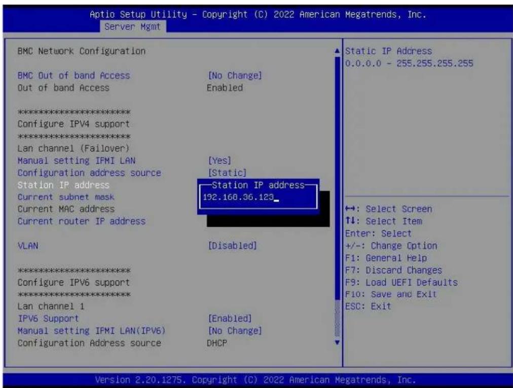
ASRock Ritch2.1.1.2 Setting Static BMC IP Address through UEFI BIOS
- Boot to UEFI BIOS SETUP page.
- Select the Server Mgmt page.
- Select the BMC Network Configuration page.
- Navigate to Manual setting IPMI LAN and select the [Yes].
- Navigate to Configuration address source and select the [Static].
- Once the Configuration address source is Static, the field of Station IP Address, Current subnet mask, and Current router IP address will display 0.0.0.0 and configurable, which indicates users can fill the new setting value into these fields. After filling the new value into these fields, press
to save the values and reboot the system to enable these configured settings values.
Figure 4. Snapshot of Configure BMC Static IP Address
text_image
Aptio Setup Utility - Copyright (C) 2022 American Megatrends, Inc. Server Mgmt BMC Network Configuration BMC Out of band Access [No Change] Out of band Access Enabled ************************** Configure IPV4 support ************************** Lan channel (Failover) Manual setting IFMI LAN [Yes] Configuration address source [Static] Station IP address Station IP address Current subnet mask 192.160.36.123_ Current MAC address Current router IP address VLAN [Disabled] ************************** Configure IPV6 support ************************** Lan channel 1 IPV6 Support [Enabled] Manual setting IFMI LAN(IPV6) [No Change] Configuration Address source DHCP Static IP Address 0.0.0.0 - 255.255.255.255 +: Select Screen ↑↓: Select Item Enter: Select +/-: Change Option F1: General Help F7: Discard Changes F9: Load UEFI Defaults F10: Save and Exit ESC: Exit Version 2.20.1275. Copyright (C) 2022 American Megatrends, Inc.2.2 Username and Password
Once users connect to the BMC WebUI service through the browser, the BMC WebUI service login page will display on the browser.
Figure 5. Snapshot of BMC WebUI Service Login Page

text_image
ASRockRack Username Password US - English Remember Username Sign me in I forgot my passwordThe fields description is shown as follows:
- Username: Enter the user identifier (UID) of the account to who wants to log in.
- Password: Enter the password of the account to which wants to log in.
● Language Menu: Changes BMC WebUI supported language. - Remember Username: Check the box if users want to keep the username in the browser settings.
- Sign me in: After entering the required credentials, click the Sign me in to log in to the BMC WebUI service.
- I forgot my password: The user can generate a new password using
this link if the user forgot the password.
- Default Username and Password:
■ Username: admin
■ Password: admin
Note: If the user uses the default username and password to log in to the BMC WebUI service for the first time, the BMC will require the user to change the password.
2.3 Accessing BMC WebUI Service
The BMC WebUI service consists of various items, including menu, graphics, table, options, and configuration. The detailed information is listed in the following subsections.
Figure 6. Snapshot of BMC WebUI Service Main Page

text_image
ASRockRack macOffice US-English BIOS Sync Refresh admin Dashboard Sensor System Information Logs & Reports IPM Event Log System Log Audio Log Video Log Post Audio Log Debug Log Settings Remote Control Image Redirection Power Control Miscellaneous Maintenance Sign out Dashboard Control Panel 0 d 0 hrs Power On Hours Product Information MS Model Name ROFEDR-27 0 Firmishing Desasementics More info 5 Access Logs More info Firmware Information BHC Firmware Version 3.18.00 BIOS Firmware Version Network Information Details MAC Address 0015099(1):AASF UI Network Media BHCP IPv4 Address 165.58L36.196 UI Network Media BHCP IPv6 Address 5 Today (s) Details No events for today.. 30 days (s) Details No events for last 30 days.. Sensor Monitoring All sensors are good now! Currently recovered2.3.1 Menu Bar
The Menu Bar provides a group of functional feature tabs for users to configure the BMC configuration. The Menu Bar is located on the left side of BMC WebUI.
Figure 7. Snapshot of Menu Bar

text_image
ASRockRack Host Online UID Off Dashboard Sensor System Information Logs & Reports IPMI Event Log System Log Audit Log Video Log Post Code Log Debug Log Settings Remote Control Image Redirection Power Control Miscellaneous Maintenance Sign outThe supported feature tabs are listed in the following:
- Dashboard
- Sensor
- System Information
- Logs and Reports
■ IPMI Event Log
■ System Log
■ Audit Log
■ Video Log
■ Post Code log
■ Debug Log
- Settings
- Remote Control
- Image Redirection
● Power Control - Miscellaneous
- Maintenance
- Sign Out
The Host Online/Host Offline icon indicates the system power state is Power ON/Power Off. Click the icon, then navigate to the Power Control page.
The UID On/UID Off icon indicates the current UID LED status. Click the icon, then navigate to the UID Control page.
2.3.2 Quick Link and User Information
The Quick Link and User Information are located in the upper right corner of BMC WebUI. It provides various functional feature links for users quickly view the information or change the specific configuration.
Figure 8. Snapshot of Quick Link and User Information

text_image
US - English BIOS Sync Refresh admin admin - Administrator Profile Sign out2.3.2.1 Quick Links
The supported Quick Links and their actions are listed in the following:
- Message: Click Message (☑) Quick Link to quickly view the received event logs or alert messages in the popup window. Click the message listed in the popup window, then navigates to the Logs and Reports page to view the details.
- Notification: Click Notification (▲) Quick Link to quickly view the received notification in the popup window.
- Language Menu: Click Language Menu (US - English) to change the supported BMC WebUI language.
- BIOS: Click BIOS ( i BIOS) Quick Link to view the BIOS settings.
- Sync: Click Sync (Sync) Quick Link to turn on/off the sync feature. Turn on this feature that syncs the latest Sensor and Event Log updates.
- Refresh: Click Refresh (Refresh) Quick Link to reload current page.
2.3.2.2 User Information
The User Information shows the logged-in user information.
Click User Information ( ) Quick Link to show more information on the currently logged-in user. The currently logged-in user's username will show on the Quick Link.
Click the Profile button in the popup window, then navigate to the User Management Configuration page of the currently logged-in user.
Click the Sign out button in the popup window, and sign out the current session.
Figure 9. Snapshot of User Information and Popup Window

text_image
admin admin - Administrator Profile Sign out2.3.2.3 User Privilege
BMC WebUI service provides five user privilege levels for the administrator to manage user account privilege. The details in the following:
● None: Not allow login and access BMC WebUI Service.
- User: Only perform the allowed commands.
- Operator: All commands are allowed except configuration commands that can change the behavior of the out-of-band interfaces.
- OEM: All OEM commands are allowed.
- Administrator: All commands are allowed.
2.4 Dashboard
BMC Dashboard provides overall information on system status.
To view the Dashboard page, click the Dashboard tab from the menu bar.
Figure 10. Snapshot of Dashboard Page

text_image
Dashboard Control Panel 0 d 5 hrs Power-On Hours 5 Pending Doassertors More info 2 Access Logs More info Product Information MB Model Name ROMED8-2T Firmware Information BMC Firmware Version 3.19.00 BIOS Firmware Version 13.29F PSP Firmware Version 0.C0J82 Microcode Version 0830104d Network Information Details MAC Address D0:3099:F1:A4:BF V4 Network Mode DHCP* IPv4 Address 192.168.37.6 V8 Network Mode DHCP* IPv6 Address = Today (i) details system_event 1 event 30 days (ss) Details voltage 63 events Sensor Monitoring All sensors are good now! Currently recoveredThe items on the Dashboard page are described in the following subsections.
2.4.1 Power-On Hours
It indicates the system power-on time and keeps on accumulating when the system is powered. After flashing a new BMC firmware image, the data of power-on time to be cleared to zero.
2.4.2 Pending Deassertions
It indicates the number of all pending events which are generated by various sensors and waiting for de-asserted.
Click the More Info link, then navigate to the Event Log page to view all the event logs information.
2.4.3 Access Log
It indicates the number of Access Logs which are generated by users accessing the BMC WebUI.
Click the More Info link then navigate to the Audit Log page to view all of the access logs information.
2.4.4 Product Information
It lists related components' names, such as mainboard name, system name, etc.
2.4.5 Firmware Information
It lists related firmware components information such as BMC firmware version, BIOS firmware version, CPLD firmware version, microcode version, etc.
2.4.6 Network Information
It lists related network configuration information such as BMC MAC address,
IPv4/IPv6 address, IPv4/IPv6 network mode, etc.
Click the Details link then navigate to the Network IP Settings page to view more network configuration information or configure network settings.
2.4.7 Today and 30 Days
This item lists all the event logs which are generated by various sensors.
Click the Details link on today and 30 days item then navigate to the Event Log page to view all event logs, which are filtered by today and 30 days respectively.
2.4.8 Sensor Monitoring
It lists all the critical sensors on the system.
Click the listed critical sensor, then navigate to the Sensor detail page to view all information on the selected sensor.
2.5 Sensor
The Sensor Reading page provides related information on all sensors in the system.
To view the Sensor Reading page, click the Sensor tab from the menu bar.
Figure 11. Snapshot of Sensor Reading Page

text_image
Sensor Reading Live reading of all sensor Critical Sensors (0) All threshold sensors are normal Discrete Sensor States (9) Sensor Name State chassisintr No event assertion PROCHOT_CPU No event assertion THERMTRIP_CPU No event assertion STS_CPU_RDS No event assertion STS_CPU_MCE No event assertion STS_PSU1 No event assertion STS_PSU2 No event assertion WATCHDOG2 No event assertion PowerUnit No event assertion Normal Sensors (35) Sensor Name Reading Behavior VOLT_3VSB 1.36 V VOLT_5VSB 4.92 V2.5.1 Sensor Detail
Click on the specific sensor from the Sensor Reading page then navigate to the Sensor detail page to view more information about the selected sensor, including sensor threshold values, events, and graphical representation.
Figure 12. Snapshot of Sensor Detail Page
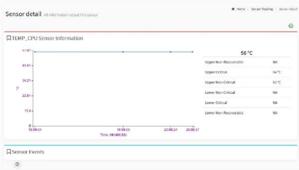
line
| Time (HH:MM:SS) | Temperature (°C) | | --------------- | ---------------- | | 19:59:04 | 57.01 | | 19:59:56 | 57.01 | | 20:00:24 | 57.01 | | 20:00:37 | 57.01 |There are six types of threshold values are listed on the page:
• Upper Non-Recoverable (UNR)
• Upper Critical (UC)
• Upper Non-Critical (UNC)
- Lower Non-Critical (LNC)
- Lower Critical (LC)
- Lower Non-Recoverable (LNR)
The event triggered by the selected sensor will be listed in the Sensor Events group.
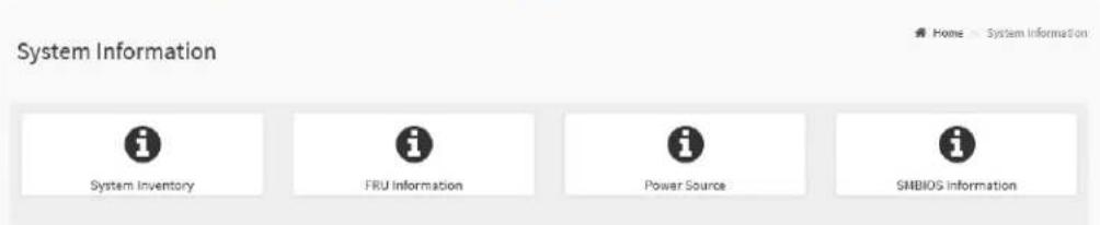
2.6 System Information
System Information page provides devices information of the system, including System Inventory, FRU Information, Power, and SMBIOS information.
Figure 13. Snapshot of System Information Page
text_image
System Information System Inventory FRU Information Power Source SMBIOS InformationThe details about each feature are listed in the following.
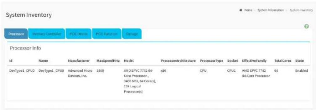
2.6.1 System Inventory
System Inventory page provides information on devices that are installed in the host, including Processor, Memory Controller, PCIe Device, PCIe function, and Storage.
To view the System Inventory page, click the System Inventory tab from the System Information page.
The details about each feature are listed in the following.
2.6.1.1 Processor
Processor page provides various information about each processor installed in the host.
Figure 14. Snapshot of System Inventory Page
text_image
System Inventory Processor Memory Controller PCI Device PCI Function Storage Processor Info id Name Manufacturer MaxSpeedMHz Model ProcessorArchitecture ProcessorType Socket EffectiveFamily TotalCores State DevType1_CPU0 DevType1_CPU0 Advanced Micro Devices, Inc. 3400 AMD EPYC 7742 64-Core Processor, 3400 MHz, 64 Core(s), 138 Logical Processor(s) x89 CPU CPU1 AMD EPYC 7742 64-Core Processor 64 EnabledThe information listed on the page includes
• Id
- Name
- Manufacturer
- MaxSpeedMHz
- Model
- ProcessorArchitecture
- ProcessorType
- Socket
- EffectiveFamily
- TotalCores
- State
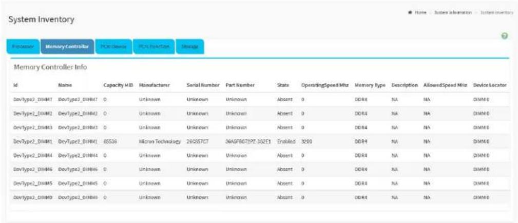
2.6.1.2 Memory Controller
Memory Controller page provides various information about each memory module installed in the host.
Figure 15. Snapshot of Memory Controller Page
text_image
System Inventory Processor Memory Controller PCE_Dlms PCI3_Function Storage Memory Controller Info Id Name Capacity MIB Manufacturer Serial Number Part Number Stats OperatingSpeed MHz Memory Type Description AllowedSpeed MHz Device Locator DevType2_DIMM7 DevType2_DIMM47 0 Unknown Unknown Unknown Absent 0 DDR4 N/A N/A DIMM 6 DevType2_DIMM2 DevType2_DIMM42 0 Unknown Unknown Unknown Absent 0 DOR4 N/A N/A DIMM 6 DevType2_DIMM3 DevType2_DIMM3 0 Unknown Unknown Unknown Absent 0 DOR4 N/A N/A DIMM 6 DevType2_DIMM1 DevType2_DIMM1 65538 Micron Technology 28C857C7 36ASF8072PZ-30ZE1 Enabled 3200 DOR4 N/A N/A DIMM 6 DevType2_DIMM4 DevType2_DIMM44 0 Unknown Unknown Unknown Absent 0 DOR4 N/A N/A DIMM 6 DevType2_DIMM6 DevType2_DIMM6 0 Unknown Unknown Unknown Absent 0 DOR4 N/A N/A DIMM 6 DevType2_DIMM5 DevType2_DIMM5 0 Unknown Unknown Unknown Absent 0 DOR4 N/A N/A DIMM 6 DevType2_DIMM9 DevType2_DIMM9 0 Unknown Unknown Unknown Absent 0 DOR4 N/A N/A DIMM 6The information listed on the page includes
• Id
- Name
- Capacity Mib
- Manufacturer
- Serial Number
- Part Number
• State
- OperatingSpeed Mhz
- Memory Type
- Description
- AllowedSpeed Mhz
- Device Locator
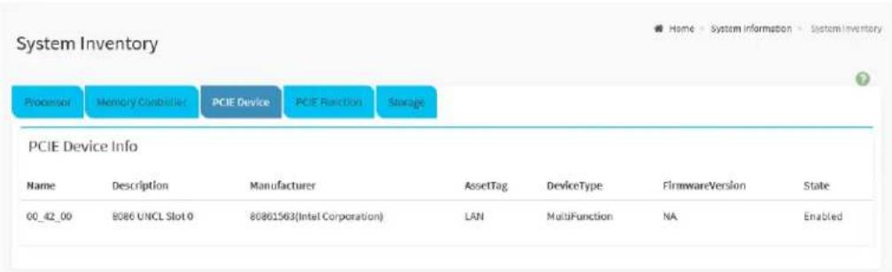
2.6.1.3 PCIE Device
PCIE Device page provides various information about each PCIe device installed in the host.
Figure 16. Snapshot of PCIE Device Page
text_image
System Inventory Processor Memory Controller PCIE Device PCIE Function Storage PCIE Device Info Name Description Manufacturer AssetTag DeviceType FirmwareVersion State 00_42_00 8086 UNCL Slot 0 80861563(Intel Corporation) LAN MultiFunction NA EnabledThe information listed on the page includes
- Name
- Description
- Manufacturer
- AssetTag
- DeviceTpye
- FirmwareVersion
• State
2.6.1.4 PCIE Function
PCIE Function page provides various information about each PCIe device installed in the host.
Figure 17. Snapshot of PCIE Function Page

text_image
System Inventory Programs Memory Connection PCE Device PCE Function Snergy PCIE Function Info Id Name Device Linked Device Class Class Code Device Id Vendor Id Function Id Revision Id Sub System Id Sub System Vendor Id(State DevType3_LANN_DevIndex2C DevType3_LANN_DevIndex2C 01_42_00 NetworkController Dx020000 0x1563 0x8088 0 0x01 0x1563 0x1849 Enabled DevType3_DevIndex2D DevType3_DevIndex2D 01_42_00 NetworkController Dx020000 0x1563 0x8089 1 0x01 0x1563 0x1849 EnabledThe information listed on the page includes
• Id
- Name
- Device Linked
- Device Class
- Device Code
- Device Id
- Vendor Id
- Revision Id
- Sub System Id
- Sub System Vendor Id
• State
2.6.1.5 Storage
Storage page provides various information about each storage drive and storage controller installed in the host.
Figure 18. Snapshot of Storage Page

text_image
System Inventory Processor Memory Controller POE Devise POE Function Storage Storage Drive Info Name SerialNumber Manufacturers Location Protocol Model Revision EncryptionStatus MediaType State Information Not Available Storage Controller Info MemberId SerialNumber Model FirmwareVersion SpeedGbps State 1 Not Available Not Available Not Available 6 Enabled 2 Not Available Not Available 1.10 3 Enabled 0 Not Available Not Available 1.10 3 Enabled 6 Not Available Not Available Not Available 6 Enabled 3 Not Available Not Available Not Available 6 Enabled 4 Not Available Not Available Not Available 6 Enabled 1 Not Available Not Available 1.10 3 EnabledThe information listed on the page includes:
- Storage Drive
Name
SerialNumber
■ Manufacturer
■ Location
■ Protocol
■ Model
Revision
■ EncryptionStatus
■ MediaType
■ State
- Storage Controller
■ MemberId
SerialNumber
■ Model
■ FirmwareVersion
■ SpeedGbps
■ State
2.6.2 FRU Information
FRU Information page provides various information on BMC FRU devices. Three types of information are listed on the FRU Information page includes Chassis Information, Board Information, and Product Information.
To view the FRU Information page, click the FRU Information tab from the System Information page
Figure 19. Snapshot of FRU Information Page

text_image
FRU Information Field Replaceable Units Available FRU Devices FRU Device ID 0 w FRU Device Name BMC_FRU Chassis Information Board Information Product Information Chassis Information Area Format Version 1 Board Information Area Format Version 1 Product Information Area Format Version Chassis Type Main Server Chassis Version Chassis Part Number Language 25 Language 25 Chassis Serial Number Manufacture Date Time Mon Sep 21 21:22:00 Product Manufacturer ASRock Rack Inc. Chassis Manufacturer(Extra) Board Manufacturer ASRock Rack Inc. Chassis version(Extra) Board Product Name ROMED8-3T Product Name Chassis asset tag(Extra) Board Serial Number Product Part Number R2.91 Product Part Number Product Version 00 Chassis sku number(Extra) Board Part Number Product Serial Number 162202000000 Chassis model(Extra) FRU File ID Asset Tag FRU File ID Board version(Extra) product UUID(Extra) 028111b21d8221da9ef6d0509f1a4ff Board asset tag(Extra) product sku number(Extra) product family(Extra)The information listed on the page includes
Available FRU Devices:
- FRU Device ID
- FRU Device Name
Chassis Information
Board Information
Product Information
2.6.2.1 Chassis Information
- Chassis Information Area Format Version
- Chassis Type
- Chassis Part Number
- Chassis Serial Number
- Chassis Manufacturer (Extra)
- Chassis Version (Extra)
- Chassis Asset Tag (Extra)
- Chassis SKU Number (Extra)
- Chassis Model (Extra)
2.6.2.2 Board Information
- Board Information Area Format Version
- Language
● Manufacture Date Time - Board Manufacturer
- Board Product Name
- Board Serial Number
- Board Part Number
- FRU File ID
- Board Version (Extra)
● Board Asset Tag (Extra)
2.6.2.3 Product Information
● Product Information Area Format Version
- Language
• Product Manufacturer
- Product Name
● Product Part Number
- Product Version
● Product Serial Number
- Asset Tag
- FRU File ID
- Product UUID (Extra)
● Product SKU Number (Extra)
● Product Family (Extra)
2.6.3 Power Source
Power Source page provides various information about each system power supply installed in the host.
To view the Power Source page, click the Power Source tab from the System Information page
Figure 20. Snapshot of Power Source Page
| Slot1 | Slot2 | ||
| Power Supply Status | Power Supply Error | Power Supply Status | Power Supply Error |
| AC Input Voltage | 0V | AC Input Voltage | 0V |
| AC Input Current | 0A | AC Input Current | 0A |
| AC Input Power | 0W | AC Input Power | 0W |
| DC 12V Output Voltage | 0V | DC 12V Output Voltage | 0V |
| DC 12V Output Current | 0A | DC 12V Output Current | 0A |
| DC 12V Output Power | 0W | DC 12V Output Power | 0W |
| Temperature 1 | 0℃ | Temperature 1 | 0℃ |
| Temperature 2 | 0℃ | Temperature 2 | 0℃ |
| Fan 1 | 0 RPM | Fan 1 | 0 RPM |
| Fan 2 | 0 RPM | Fan 2 | 0 RPM |
| DC 12V Max Output Voltage | 0V | DC 12V Max Output Voltage | 0V |
| DC 12V Max Output Current | 0A | DC 12V Max Output Current | 0A |
| DC 12V Max Output Power | 0W | DC 12V Max Output Power | 0W |
| ID | ID | ||
| Model | Model | ||
| Revision | Revision | ||
| Serial Number | Serial Number | ||
The information listed on the page includes:
Slot 1 and Slot 2:
● Power Supply Status
- AC Input Voltage
- AC Input Current
- AC Input Power
• DC 12V Output Voltage
• DC 12V Output Current
- DC 12V Output Power
- Temperature 1
- Temperature 2
- Fan 1
- Fan 2
• DC 12V Max Output Voltage
• DC 12V Max Output Current - DC 12V Max Output Power
• ID - Model
- Revision
- Serial Number
2.6.4 SMBIOS Information
SMBIOS Information page provides various information about SMBIOS. Refer to related SMBIOS specifications for more details.
To view the SMBIOS Information page, click the SMBIOS Information tab from the System Information page
Figure 21. Snapshot of SMBIOS Information Page

text_image
SMBIOS Information System Management BIOS Download binary Entry BIOS System Board Chassis Port Port Port Port Port Port Port Port Port Port Port Port SMBIOS Name Description Version 3.2 Length 31 Maximun structure size 161Click the Download binary button on SMBIOS Information to download the raw data of SMBIOS.
2.7 Logs & Reports
Logs & Reports provides various functional features for users to audit the logs triggered by multiple devices or conditions.
Supported features are listed in the following subsections including
- IPMI Event Log
- System Log
- Audit Log
- Video Log
- Post Code Log
- Debug Log
The Logs & Reports tab is located at the menu bar, click Log & Reports tab to expand all the supported features tabs.
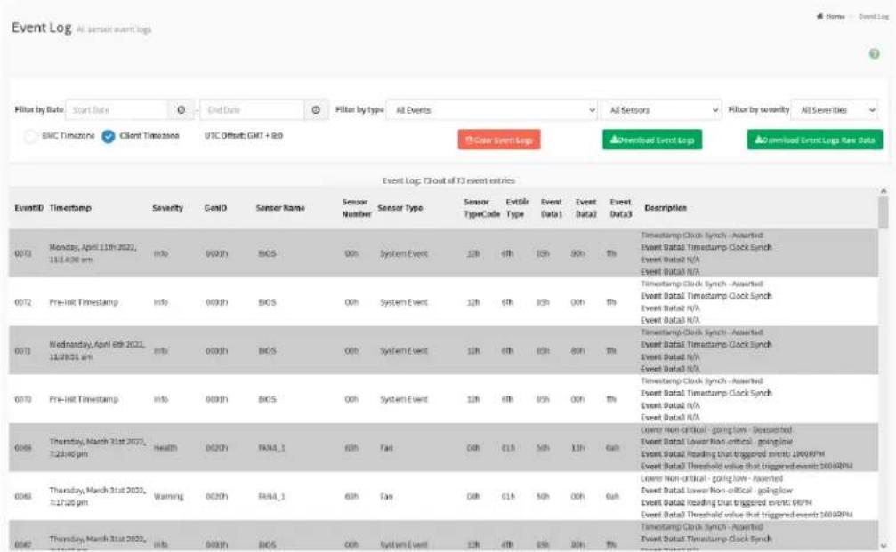
2.7.1 IPMI Event Log
IPMI Event Log page provides various event logs information which is generated by different sensors for users to monitor system status.
To view the IPMI Event Log page, click Logs & Reports tab from the menu bar to expand the sub-menu bar, then click the IPMI Event Log tab from the sub-menu bar.
Figure 22. Snapshot of IPMI Event Log Page
text_image
Event Log: T3 out of T3 event entries EventID Timestamp Severity GenID Sensor Name Sensor Number Sensor Type Sensor TypeCode Extile Type Event Data1 Event Data2 Event Data3 Description 0073 Monday, April 11th 2022, 11/14/2026 am info 0000h BIOS 00h System Event 12h 6th 8th 9th % Time stamp Clock Synch - Awarded Event Data1 Timestamp Clock Synch Event Data2 N/A Event Data3 N/A 0072 Pre-Init Timestamp info 0000h BIOS 00h System Event 12h 6th 8th 9th % Time stamp Clock Synch - Awarded Event Data1 Timestamp Clock Synch Event Data2 N/A Event Data3 N/A 0071 Wednesday, April 09th 2022, 11/28/2021 am info 0000h BIOS 00h System Event 12h 6th 8th 9th % Time stamp Clock Synch - Awarded Event Data1 Timestamp Clock Synch Event Data2 N/A Event Data3 N/A 0070 Pre-Init Timestamp info 0000h BIOS 00h System Event 12h 6th 8th 9th % Time stamp Clock Synch - Awarded Event Data1 Timestamp Clock Synch Event Data2 N/A Event Data3 N/A 0068 Thursday, March 31st 2022, T:28:40 pm Health 0020h PANA_1 6th Fan 04h 81h 5th 13h Goh Lower Non-critical - going low - Awarded Event Data1 Lower Non-critical - going low Event Data2 Reading that triggered event: 1800RPM Event Data3 Threshold value that triggered event: 500RPM 0068 Thursday, March 31st 2022, T:17:25 pm Warning 0030h PANA_1 6th Fan 04h 81h 5th 04h Goh Lower Non-critical - going low Event Data2 Reading that triggered event: 68PN Event Data3 Threshold value that triggered event: 500RPM 0067 Thursday, March 31st 2022, T:17:45 pm Info 0030h BIOS 00h System Event 12h 6th 8th 9th % Hg % Time stamp Clock Synch - Awarded Event Data1 Timestamp Clock Synch Event Data2 N/A Event Data3 N/AThe fields on the IPMI Event Log page include:
- Filter by Date: Filter the records by specific Start Date and End Date using Calendar.
- Filter by Type: Filter the records by specific Event Type and Sensor Type.
- BMC and Client Time Zone: Select either one to switch the current UTC offset value. The timestamp value will be updated when the option has been changed.
- UTC Offset: Display the current UTC Offset value.
-
Clear Event Logs: Click the Clear Event Logs button to clear the records.
-
Download Event Logs: Click the Download Event Logs button to download all records information with the specific data format.
- Download Event Logs Raw Data: Click the Download Event Logs button to download all records information in the raw data format.
The information listed on the page includes
- EventID
- Timestamp
- Severity
- GenID
- Sensor Name
- Sensor Number
- Sensor Type
- Sensor TypeCode
- EvtDir Type
- Event Data1
- Event Data2
- Event Data3
- Description
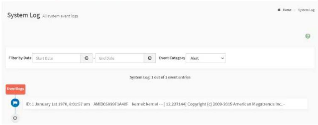
2.7.2 System Log
System Log page provides various system events information which is generated by the BMC system.
To view the System Log page, click Logs & Reports tab from the menu bar to expand the sub-menu bar, then click the System Log tab from the sub-menu bar.
Note: To configure this feature, users can view the Advanced Log Settings page. Click the Settings tab from the menu bar -> Log Settings -> Advanced Log Settings.
Figure 23. Snapshot of System Log Page
text_image
System Log All system event logs Filter by Date Start Date End Date Event Category Alert System Log: 1 out of 1 event entries Eventlogs ID: 1 January 1st 1970, 8:01:57 am AMID05099F1A48F kernel kernel -- [ 12.237144] Copyright (c) 2009-2015 American Megatrends Inc. -The fields on the System Log page include
- Filter by Date: Filter the records by specific Start Date and End Date using Calendar.
- Event Category: Select the target event to view related events, including Alert, Critical, Error, Notification, Warning, Debug, Emergency, and information.
2.7.3 Audit Log
Audit Log page provides user login information log for users to monitor the BMC WebUI access.
To view the Audit Log page, click Logs & Reports tab from the menu bar to expand the sub-menu bar, then click the Audit Log tab from the sub-menu bar.
Note: To configure this feature, users can view the Advanced Log Settings page. Click the Settings tab from the menu bar -> Log Settings -> Advanced Log Settings.
Figure 24. Snapshot of Audit Log Page

text_image
Audit Log: 11 out of 11 event entries Editings ID: 11 April 11th 2022, 7:53:24 pm AMID05099F1A48F spx_restservice:spx_restservice -- [1130 : 1130 INFO]https Login from IP:192.168.37.54 user:admin - ID: 10 April 11th 2022, 7:32:13 pm AMID05099F1A48F spx_restservice:spx_restservice -- [1130 : 1130 INFO]HTTPS logout from IP:192.168.37.54 user:admin - ID: 9 April 11th 2022, 4:55:24 pm AMID05099F1A48F spx_restservice:spx_restservice -- [1130 : 1130 INFO]https Login from IP:192.168.37.54 user:admin - ID: 8 April 11th 2022, 4:53:42 pm AMID05099F1A48F spx_restservice:spx_restservice -- [1130 : 1130 INFO]HTTPS logout from IP:192.168.37.54 user:admin - ID: 7 April 11th 2022, 4:06:07 pm AMID05099F1A48F spx_restservice:spx_restservice -- [1130 : 1130 INFO]https Login from IP:192.168.37.54 user:admin - ID: 6 April 11th 2022, 4:06:04 pm AMID05099F1A48F spx_restservice:spx_restservice -- [1130 : 1130 WARNING]https Login Failed from IP:192.168.37.54 user:admin - ID: 5 April 11th 2022, 4:02:42 pm AMID05099F1A48F spx_restservice:spx_restservice -- [1130 : 1130 INFO]HTTPS logout from IP:192.168.37.54 user:admin - ID: 4 April 11th 2022, 2:31:32 pm AMID05099F1A48F spx_restservice:spx_restservice -- [1130 : 1130 INFO]https Login from IP:192.168.37.54 user:admin - ID: 3 April 11th 2022, 2:31:19 pm AMID05099F1A48F spx_restservice:spx_restservice -- [1130 : 1130 INFO]HTTPS logout from IP:192.168.37.54 user:admin - ID: 2 April 11th 2022, 2:18:59 pm AMID05099F1A48F spx_restservice:spx_restservice -- [1130 : 1130 INFO]https Login from IP:192.168.37.54 user:admin -The fields on the Audit Log page include
- Filter by Date: Filter the records by specific Start Date and End Date using Calendar.
2.7.4 Video Log
Video Log provides the feature that records the video when a specific event is triggered.
To view the Video Log page, click Logs & Reports tab from the menu bar to expand the sub-menu bar, then click the Video Log tab from the sub-menu bar.
Note: To configure this feature, users can view the Video Trigger Settings.
Click the Settings tab from the menu bar -> Video Recording ->
Auto Video Settings -> Video Trigger Settings.
Figure 25. Snapshot of Video Log Page
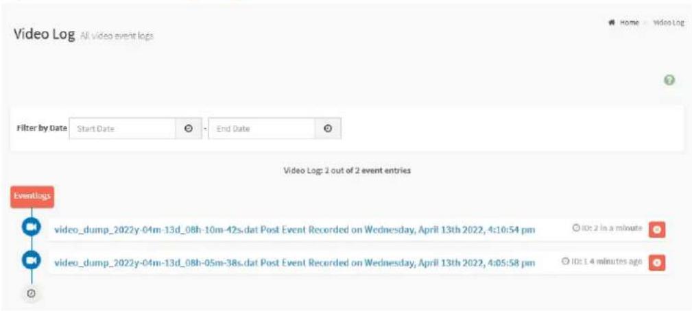
text_image
Video Log All video event logs Filter by Date Start Date End Date Video Log: 2 out of 2 event entries Eventlogs video_dump_2022y-04m-13d_08h-10m-42s.dat Post Event Recorded on Wednesday, April 13th 2022, 4:10:54 pm video_dump_2022y-04m-13d_08h-05m-38s.dat Post Event Recorded on Wednesday, April 13th 2022, 4:05:58 pm ID: 2 in a minute ID: 1.4 minutes agoClick the record listed on the page to view the recorded video triggered by events.
The fields on the Video Log page include
- Filter by Date: Filter the records by specific Start Date and End Date using Calendar.
- Delete: Click the Delete (✗) to delete this record and its video.
- Download: Click the Download ( ) to save the video file.
● Play: Click the Play (▶) to view the recorded video. -
Pause: Click the Pause (☐) to pause the video.
-
Close: Click the Close (✗) to pause the video play.
- Duration: Indicates the playback time (Duration 0:00) of the video.
2.7.5 Post Code
Post Code page provides the BIOS POST code information for users to monitor the BIOS POST process and the system power-on status.
To view the Post Code page, click Logs & Reports tab from the menu bar to expand the sub-menu bar, then click the Post Code Log tab from the sub-menu bar.
Figure 26. Snapshot of Post Code Page

text_image
Scanned screenshot of a software interface showing event logs and code log entries for 'Post Code Log' with timestamps and version numbers.The fields on the Post Code page include
- Download Post Code Log: Click the Download Post Code Log to save all BIOS POST code logs.
2.7.6 Debug Log
Debug Log page provides the feature that downloads the debug log file, which for users to download all debug logs stored in the BMC system and diagnostics the BMC system status.
To view the Debug Log page, click Logs & Reports tab from the menu bar to expand the sub-menu bar, then click the Debug Log tab from the sub-menu bar.
Figure 27. Snapshot of Debug Log Page

text_image
Debug Log Show debug events Download Debug LogThe fields on the Debug Log page include
- Download Debug Log: Click the Download Debug Log to save all BMC system debug logs.
2.8 Settings
Settings page provides various functional features for users to configure all the BMC supports services, including
- Captured BSOD
- Date & Time
- External User Services
- KVM Mouse Setting
- Log Settings
● Media Redirection Settings - Network Settings
- PAM Order Settings
- Platform Event Filter
- Services
- SMTP Settings
- SSL Settings
- System Firewall
- User Management
- Video Recording
- IPMI Interface
- Keep Share NIC Link Up
- FAN Settings
● Power Restore Policy - Password Settings
To view the Settings page, click the Settings tab from the menu bar.
Figure 28. Snapshot of Settings Page
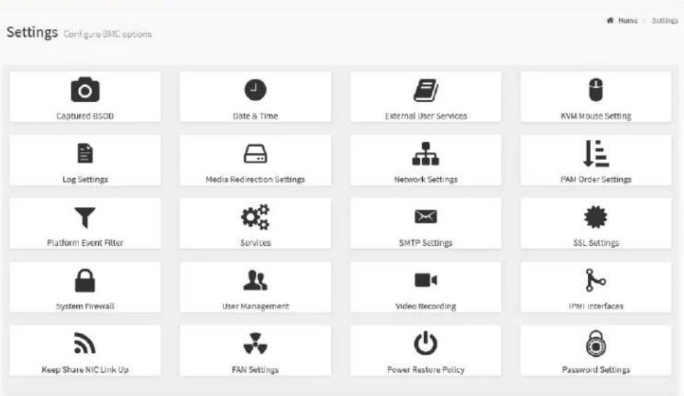
text_image
Settings Configure BMC options Captured BSOD Date & Time External User Services KVM Mouse Setting Log Settings Media Redirection Settings Network Settings PAM Order Settings Platform Event Filter Services SMTP Settings SSL Settings System Firewall User Management Video Recording IPMI Interfaces Keep Share NIC Link Up FAN Settings Power Restore Policy Password SettingsThe details about each feature are listed in the following subsections.
2.8.1 Captured BSOD
Captured BSOD page provides the feature which automatically captures the Blue Screen of Death (BSOD) when the OS kernel crash.
To view the Captured BSOD page, click the Settings -> Captured BSOD tab from the menu bar.
Figure 29. Snapshot of BSOD Page

text_image
Captured BSOD Last BSOD Screen Captured2.8.2 Date & Time
Date & Time page provides the various configuration for users to configure the date and time on the BMC.
To view the Date & Time page, click the Settings -> Date & Time tab from the menu bar.
Figure 30. Snapshot of Date & Time Page

text_image
Date & Time Notes: If the time zone is selected from the group of Manual offset (GMT/ETC time zones), the interactive map selection feature will be disabled. The new Time Zone settings will be reflected on the page only after being saved. Configure Date & Time Select Time Zone Apr 19, 2022 7:20:13 AM ( Etc/GMT) - ManualOffset/Etc/GMT Automatic NTP Date & TimeThe fields on the Date & Time page include
- Configure Date & Time: Displays time zone list containing the UTC offset along with the locations and Navigational line to select the location which can be used to display the exact local time.
- Select Time Zone: This field is used to set the date and time on the BMC.
● Automatic Date & Time: To automatically synchronize Date and Time with the NTP Server.
- Primary NTP Server: To configure a primary NTP server to use when automatically setting the date and time.
- Secondary NTP Server: To configure a Secondary NTP server to use when automatically setting the date and time.
- Clock: Click the Clock icon (°) to manually modify the Date and Time.
- Save: To save the configured settings.
Note: If the time zone is selected as Manual Offset, the map selection will be disabled. The Time Zone settings will be reflected only after saving the settings.
2.8.3 External User Services
External User Services page provides three functional feature tabs for users to configure the external user services, including
- LDAP/E-Directory Settings
● Active Directory Settings - RADIUS Settings
To view the External User Services page, click the Settings -> External User Services tab from the menu bar.
Figure 31. Snapshot of External User Services Page
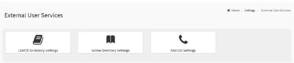
text_image
External User Services LDAP/E-Directory Settings Active Directory Settings RADIUS SettingsThe details about each feature are listed in the following subsections.
2.8.3.1 LDAP/E-Directory Settings
The Lightweight Directory Access Protocol (LDAP)/E-Directory is an application protocol for querying and modifying data of directory services implemented in Internet Protocol (IP) networks.
LDAP/E-Directory Settings page provides two functional feature tabs for users to configure the LDAP settings, including
- General LDAP/E-directory Settings
- Role Groups
To view the LDAP/E-Directory Settings page, click the Settings -> External User Services -> LDAP/E-Directory Settings tab from the menu bar.
Figure 32. Snapshot of LDAP/E-Directory Settings Page

text_image
LDAP/E-Directory Settings General LDAP/E-directory Settings Role GroupsThe details about each feature are listed in the following.
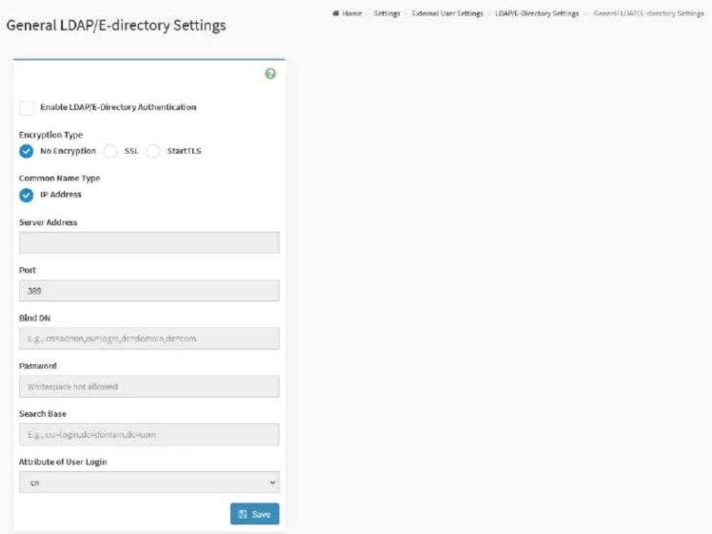
2.8.3.1.1 General LDAP/E-Directory Settings
This page provides various options for users to configure the LDAP/E-Directory Settings.
To view the General LDAP/E-Directory Settings page, click the Settings -> External User Services -> LDAP/E-Directory Settings -> General LDAP/E-Directory Settings tab from the menu bar.
Figure 33. Snapshot of General LDAP/E-Directory Settings Page
text_image
General LDAP/E-directory Settings Enable LDAP/E-Directory Authentication Encryption Type ✓ No Encryption ○ SSL ○ StartTLS Common Name Type ✓ IP Address Server Address Port 389 Blnd ON E.g., or admin, or login, or domain, or com. Password Whitespace not allowed Search Base E.g., or login, or domain, or com. Attribute of User Login cn SaveThe fields on the General LDAP/E-Directory Settings page include
- Enable LDAP/E-Directory Authentication: Click this option to enable LADP/E-Directory Settings.
- Encryption Type: Select the encryption type for LDAP/E-Directory.
■ No Encryption
■ SSL
■ StartTLS
● Common Name Type: Select the Common Name Type.
■ IP Address
■ FQDN
- Server Address: Enter the LDAP/E-Directory server address, IPv4 and IPv6 address format are supported.
Note: Enter a FQDN address if using StartTLS with FQDN.
- Port: Specify the LDAP/E-Directory Port.
- Bind DN: The Bind DN is used in bind operations, which authenticates the client to the server.
- Password: The Bind password is also used in the bind authentication operations between client and server.
- Search Base: The Search Base allows the LDAP/E-Directory server to find which part of the external directory tree is to be searched
- Attribute of User Login: The Attribute of User Login field indicates to the LDAP/E-Directory server which attribute should be used to identify the user.
Note: It only supports cn or uid.
- CA certificate file: Select CA Certificate File from the Browse field to identify the certificate of the trusted CA certs.
- Certificate File: Select the Certificate File to find the client certificate filename.
- Private Key: Select Private Key to find the client private key filename.
- Save: To save the configured settings.
Note: CA certificate file, Certificate File and Private Key are required, when SSL or StartTLS is enabled.
2.8.3.1.2 Role Groups
This page provides the feature for users to add a new group to the device.
To view the Role Groups page, click the Settings -> External User Services
-> LDAP/E-Directory Settings -> Role Groups tab from the menu bar.
Figure 34. Snapshot of Role Groups Slots
text_image
Role Groups None None None None NoneClick on the Slot icon ( ) then navigate to the Add Role Groups page.
Figure 35. Snapshot of Add Role Groups Page
text_image
Role Groups Group Name Group Domain eg. dendomain Group Privilege KVM Access VMedia Access SaveThe fields on the Add Role Groups page include
-
Group Name: Enter the Role Group Name. This name identifies the role group in LDAP/E-Directory.
● Group Domain: Enter the Role Group Domain. This is the domain where the role group is located. -
Group Privilege: Enter the Role Group Privilege. This is the level of privilege to be assigned for this role group
- KVM Access: This field used to assign the KVM privilege for this role group.
- VMedia Access: This field used to assign the VMedia privilege for this role group.
- Save: To save the configured settings.
2.8.3.2 Active Directory Settings
Active Directory (AD) is a directory structure used on Microsoft Windows based computers and servers to store information and data about networks and domains.
Active Directory Settings page provides two functional feature tabs for users to configure the Active Directory settings, including
- General Active Directory Settings
- Role Groups
To view the Active Directory Settings page, click the Settings -> External User Services -> Active Directory Settings tab from the menu bar.
Figure 36. Snapshot of Active Directory Settings Page

text_image
Active Directory Settings General Active Directory Settings Role GroupsThe details about each feature are listed in the following.
2.8.3.2.1 General Active Directory Settings
This page provides various options for users to configure the Active Directory Settings.
To view the Active Directory Settings page, click the Settings -> External User Services -> Active Directory Settings -> General Active Directory Settings tab from the menu bar.
Figure 37. Snapshot of General Active Directory Settings Page

text_image
General Active Directory Settings Enable Active Directory Authentication SSL Secret Username Secret Password User Domain Name Domain Controller Server Address 1 Domain Controller Server Address 2 Domain Controller Server Address 3 SaveThe fields on the General Active Directory Settings page include
- Enable Active Directory Authentication: Click this option to enable Active Directory Settings.
- SSL: Click this option to enable SSL support.
- Secret Username: Specify the Username of an administrator of the Active Directory Server.
- Secret Password: Specify the Password of the administrator.
- User Domain Name: Specify the Domain Name for the user e.g. MyDomain.com
-
Domain Controller Server Address 1: Enter the IP address of Active Directory server. IPv4 and IPv6 address format are supported.
-
Domain Controller Server Address 2: Enter the IP address of Active Directory server. IPv4 and IPv6 address format are supported.
- Domain Controller Server Address 3: Enter the IP address of Active Directory server. IPv4 and IPv6 address format are supported.
- Save: To save the configured settings.
2.8.3.2.2 Role Groups
This page provides the feature for users to add a new group to the device.
To view the Role Groups page, click the Settings -> External User Services
-> Active Directory Settings -> Role Groups tab from the menu bar.
Figure 38. Snapshot of Role Groups Slots
text_image
Role Groups None None None None NoneClick on the Slot icon ( ) then navigate to the Add Role Groups page.
Figure 39. Snapshot of Add Role Groups Page
text_image
Role Groups Group Name Group Domain eg, UlyDom.sin.com Group Privilege KVM Access VMedia Access SaveThe fields on the Add Role Groups page include
-
Group Name: Enter the Role Group Name. This name identifies the role group in Active Directory.
● Group Domain: Enter the Role Group Domain. This is the domain where the role group is located. -
Group Privilege: Enter the Role Group Privilege. This is the level of privilege to be assigned for this role group
- KVM Access: This field used to assign the KVM privilege for this role group.
- VMedia Access: This field used to assign the VMedia privilege for this role group.
- Save: To save the configured settings.
2.8.3.3 RADIUS Settings
Remote Authentication Dial-In User Service (RADIUS) is a networking protocol that provides centralized authentication, authorization, and accounting (AAA) management for users who connect and use a network service.
RADIUS Settings page provides two functional feature tabs for users to configure the RADIUS settings, including
- General RADIUS Settings
- Advanced RADIUS Settings
To view the RADIUS Settings page, click the Settings -> External User Services -> RADIUS Settings tab from the menu bar.
Figure 40. Snapshot of RADIUS Settings Page
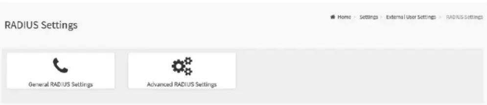
text_image
RADIUS Settings General RADIUS Settings Advanced RADIUS SettingsThe details about each feature are listed in the following.
2.8.3.3.1 General RADIUS Settings
This page provides various options for users to configure the RADIUS Settings.
To view the General RADIUS Settings page, click the Settings -> External User Services -> RADIUS Settings -> General RADIUS Settings tab from the menu bar.
Figure 41. Snapshot of General RADIUS Settings Page

text_image
General RADIUS Settings Enable RADIUS Authentication Server Address Port 1612 Secret Enable KVM Access Enable VMedia Access SaveThe fields on the General RADIUS Settings page include
- Enable RADIUS Authentication: Check this option to enable RADIUS Authentication.
- Server Address: Specify RADIUS Server Address.
● Port: Specify the RADIUS Port number. - Secret: Specify RADIUS Server Secret (Password).
- Enable KVM Access: This field used to assign the KVM privilege for authenticated users.
- Enable VMedia Access: This field used to assign the VMedia privilege for authenticated users.
- Save: To save the configured settings.
2.8.3.3.2 Advanced RADIUS Settings
This page provides various options for users to configure the RADIUS authorization.
To view the Advanced RADIUS Settings page, click the Settings -> External User Services -> RADIUS Settings -> Advanced RADIUS Settings tab from the menu bar.
Figure 42. Snapshot of Advanced RADIUS Settings Page

text_image
Advanced RADIUS Settings RADIUS Authorization Administrator H=4 Operator H=3 User H=2 OEM Proprietary H=1 No Access H=0 SaveThe fields on the Advanced RADIUS Settings page include
- Administrator: Enter the Vendor-Specific value for Administrator.
- Operator: Enter the Vendor-Specific value for Operator.
- User: Enter the Vendor-Specific value for User.
- OEM Proprietary: Enter the Vendor-Specific value for OEM Proprietary.
- No Access: Enter the Vendor-Specific value for No Access.
- Save: To save the configured settings.
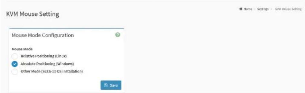
2.8.4 KVM Mouse Setting
In the BMC WebUI service, Redirection Console handles mouse emulation from local window to remote screen in either of three methods: Relative Mouse mode, Absolute Mouse mode, and Other Mouse mode.
To view the KVM Mouse Settings page, click the Settings -> KVM Mouse Setting tab from the menu bar.
Figure 43. Snapshot of KVM Mouse Setting Page
text_image
KVM Mouse Setting Mouse Mode Configuration Mouse Mode Relative Positioning (Linux) Absolute Positioning (Windows) Other Mode (SLES-11 OS installation) SaveThe fields on the KVM Mouse Setting page include
- Relative Positioning (Linux): The relative mode sends the calculated relative mouse position displacement to the server.
- Absolute Positioning (Windows): The absolute position of the local mouse is sent to the server. Recommended for Windows or later Linux releases.
- Other Mode (SLES-11 OS Installation): This option sends the calculated displacement from the local mouse in the center position to the server.
- Save: To save the configured settings.
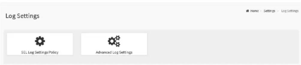
2.8.5 Log Settings
Log Settings page provides two functional feature tabs for users to configure the log policy and advance settings, including
- SEL Log Settings Policy
- Advanced Log Settings
To view the Log Settings page, click the Settings -> Log Settings tab from the menu bar.
Figure 44. Snapshot of Log Settings Page
text_image
Log Settings SEL Log Settings Policy Advanced Log SettingsThe details about each feature are listed in the following.
2.8.5.1 SEL Log Settings Policy
This page provides various options for users to configure the log policy for the event log.
To view the SEL Log Settings Policy page, click the Settings -> Log Settings -> SEL Log Settings Policy tab from the menu bar.
Figure 45. Snapshot of SEL Log Settings Policy Page

text_image
SEL Log Settings Policy Log Policy ✓ Linear Storage Policy ○ Circular Storage Policy SaveThe fields on the SEL Log Settings Policy page include
- Log Policy
■ Linear Storage Policy: Click this option to enable Linear Storage Policy.
■ Circular Storage Policy: Click this option to enable Circular Storage Policy.
- Save: To save the configured settings.
2.8.5.2 Advanced Log Settings
This page provides various options for users to configure the advanced log settings for the event log.
To view the Advanced Log Settings Policy page, click the Settings -> Log Settings -> Advanced Log Settings tab from the menu bar.
Figure 46. Snapshot of Advanced Log Settings Page

text_image
Advanced Log Settings System Log Local Log Remote Log Port Type UDP TCP File Size 50000 Rotate Count 0 Remote Log Server Server IP or Hostname Remote Server Port 0 Enable Audit Log SaveThe fields on the Advanced Log Settings page include
- System Log: Click this option to enable System Log to view all system events for this device.
- Local Log: Click this option to save the log locally (BMC).
- Remote Log: Click this option to save the logs in a remote machine.
- Port Type: Port Type is supported with enable Remote Log, select either UDP or TCP for Remote Log feature used.
■ UDP
TCP
- File Size: Specify the size of the file in bytes if the selected log type is local.
- Rotate Count: To back up the log information in back up files. When log
information exceeds the file size, the old log information is automatically moved to back up files based on the rotate count value. If rotate count is zero, then old log information gets cleared permanently.
Note: File Size and Rotate Count options will be available only when Local Log is enabled.
- Remote Log Server: Specify the Remote server address to log the system events.
- Remote Server Port: Specify the Remote server port address to log the system events.
- Enable Audit Log: Click this option to enable Audit Log to view all audit events for this device.
- Save: To save the configured settings.
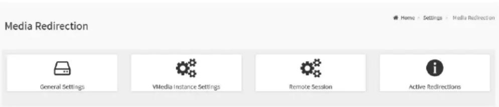
2.8.6 Media Redirection
Media Redirection page provides various functional feature tabs for users to configure the media into BMC for redirection, including
- General Settings
- VMedia Instance Settings
- Remote Session
● Active Redirections
To view the Media Redirection page, click the Settings -> Media Redirection tab from the menu bar.
Figure 47. Snapshot of Media Redirection Page
text_image
Media Redirection General Settings VMedia Instance Settings Remote Session Active RedirectionsThe details about each feature are listed in the following.
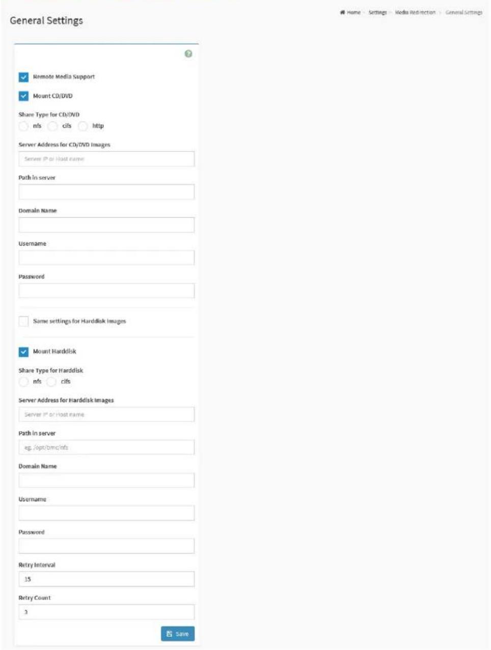
2.8.6.1 General Settings
This page provides various options for users to configure the general media settings.
To view the General Settings page, click the Settings -> Media Redirection -> General Settings tab from the menu bar.
Figure 48. Snapshot of General Settings Page
text_image
General Settings Remote Media Support Mount CD/DVD Share Type for CD/DVD nfs cifs http Server Address for CD/DVD Images Server IP or Host name Path in server Domain Name Username Password Same settings for Harddisk Images Mount Harddisk Share Type for Harddisk nfs cifs Server Address for Harddisk Images Server IP or Host name Path in server eg /opt/bmc/nts Domain Name Username Password Retry Interval 15 Retry Count 3 SaveThe fields on the General Settings page include
- Remote Media Support: Click this option to enable Remote Media Support.
- Mount CD/DVD: Click this option to enable Mount CD/DVD feature.
- Mount Harddisk: Click this opiotn to enable Mount Harddisk feature.
● Share Type for CD/DVD: Select Share Type for CD/DVD.
nfs
■ cifs
■ http
• Share Type for Harddisk: Select Share Type for Harddisk.
Nfs
■ cifs
- Server Address for CD/DVD Images: Address of the server where the remote media images are stored.
- Server Address for Harddisk Images: Address of the server where the remote media images are stored.
● Path in server: Source path to the remote media images.
- Domain Name: Enter the Domain Name if CIFS share type is selected.
- Username: Enter the Username if CIFS share type is selected.
- Password: Enter the Password if CIFS share type is selected.
- Same settings for Harddisk Images: Click this option to be applied the server information entered for CD/DVD media type to the Hard disk remote media type as well.
● Retry Interval: Enter the retry interval to reconnect RMedia.
- Retry Count: Enter the retry count to reconnect RMedia.
- Save: To save the configured settings.
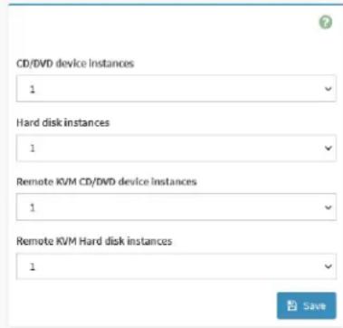
2.8.6.2 VMedia Instance Settings
This page provides various options for users to configure the Virtual Media device settings.
To view the VMedia Instance Settings page, click the Settings -> Media Redirection -> VMedia Instance Settings tab from the menu bar.
Figure 49. Snapshot of VMedia Instance Settings Page
VMedia Instance Settings
Home - Settings > Media Redirection > VMedia Instance Settings
text_image
CD/DVD device instances 1 Hard disk instances 1 Remote KVM CD/DVD device instances 1 Remote KVM Hard disk instances 1 SaveThe fields on the VMedia Instance Settings page include
- CD/DVD device instances: Select the number of CD/DVD devices that are to be supported for Virtual Media redirection.
- Hard disk instances: Select the number of Hard disk devices to be supported for Virtual Media redirection.
- Remote KVM CD/DVD device instances: Select the number of Remote KVM CD/DVD devices that are to be supported for Virtual Media redirection
- Remote KVM Hard disk instances: Select the number of Remote KVM Hard disk devices to be supported for Virtual Media redirection.
- Save: To save the configured settings.
2.8.6.3 Remote Session
This page provides various options for users to configure the Remote Session configuration settings.
To view the Remote Session Settings page, click the Settings -> Media Redirection -> Remote Session tab from the menu bar.
Figure 50. Snapshot of Remote Session Page

text_image
Remote Session KVM Client Type ✓ JViewer/HSViewer ○ VNC ✓ KVM Single Port Application Keyboard Language Auto Detect (AD) Virtual Media Attach Mode Auto Attach Retry Count 3 Retry Time Interval(Seconds) 10 ✓ Server Monitor OFF Feature Status □ Automatically OFF Server Monitor, When KVM Launches SaveThe fields on the Remote Session page include
- KVM Client Type: Select either JViewer/H5Viewer or VNC for KVM Client.
■ JViewer/H5Viewer
■ VNC
- KVM Single Port Application: Click this option to enable Single Port Application support in BMC.
● Keyboard Language: Select the Keyboard Language.
● Virtual Media Attach Mode: Select the Virtual Media Attach Mode. - Retry Count: Number of times to be retried when a KVM failure occurs. Retry count ranges from 1 to 20.
-
Retry Time Interval (Seconds): Number of seconds to wait for subsequent retries. Time interval ranges from 5 to 30 seconds.
-
Server Monitor OFF Feature Status: Click this option to enable the Server Monitor OFF feature. Users can Lock or Unlock the local host monitor from the remote KVM window if this feature is enabled.
● Automatically OFF Server Monitor, When KVM Launches: Click this option to enable this feature.
● VNC Connection Types: Select either VNC over SSH or VNC on Stunnel for VNC Connection.
■ VNC over SSH
■ VNC over Stunnel - Save: To save the configured settings.
2.8.6.4 Active Redirections
This page provides various options for users to configure the Remote Session configuration settings.
To view the Active Redirections page, click the Settings -> Media
Redirection -> Active Redirections tab from the menu bar.
Figure 51. Snapshot of Active Redirections Page

text_image
Remote Media Emulate CD/DVD/HDD Images in the network to host as media through BMC Media Type Media Instance Image Name Redirection Status Connected Server Session Index CD/DVD 0 Rocky-8.5-x86_64-dvd1.iso Started with media boost 0 Refresh Image List Sync Image StatusThe fields on the Active Redirections page include
● Media Type: The type Media devices supported for Active Redirections.
● Media Instance: The number of Media devices supported for Active Redirections.
- Image Name: The name of Media devices supported image for Active Redirections.
- Redirection Status: The status Media for Active Redirections.
- Connected Server Session Index: Indicates the number of connected server session index.
● Play: Click Play ( ▶ ) button to redirect the selected image.
- Stop: Click Stop ( ) button to stop the remote image redirection.
- Clear: Click Clear ( △ ) button to clear the selected image from the BMC.
- Refresh Image List: Click Refresh Image List (Q) to get the latest list of Images from the Remote storage server.
- Sync Image Status: Click Sync Image Status (✗) to Turn on/off the redirection status of Images from the BMC.
2.8.7 Network Settings
Network Settings page provides various options for users to configure the network settings for the available LAN channels, including
• Network IP Settings
• Network Bond Configuration
• DNS Configuration
To view the Network Settings page, click the Settings -> Network Settings tab from the menu bar.
Figure 52. Snapshot of Network Settings Page

text_image
Network Settings Network IP Settings Network Bond Configuration DNS ConfigurationThe details about each feature are listed in the following.
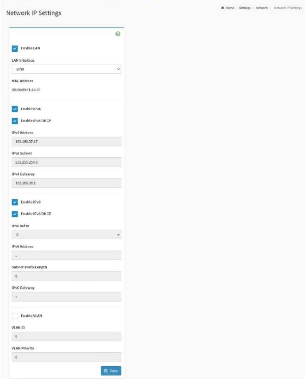
2.8.7.1 Network IP Settings
This page provides various options for users to configure the Network IP Settings.
To view the Network IP Settings page, click the Settings -> Network Settings -> Network IP Settings tab from the menu bar.
Figure 53. Snapshot of Network IP Settings Page
text_image
Network IP Settings Enable LAN LAN Interface eth0 MAC Address D0:50:99:F1AA:BF Enable IPv4 Enable IPv4 DHCP IPv4 Address 192.168.37.17 IPv4 Subnet 255.255.254.0 IPv4 Gateway 192.168.36.1 Enable IPv6 Enable IPv6 DHCP IPv6 Index 0 IPv6 Address : Subnet Prefix Length 0 IPv6 Gateway : Enable VLAN VLAN ID 0 VLAN Priority 0 SaveThe fields on the Network IP Settings page include
- Enable LAN: Click this option the enable LAN support for the interface.
● LAN Interface: Lists the supported LAN interface, select the LAN interface to be configured.
● MAC Address: Indicates the selected LAN interface MAC address. - Enable IPv4: Click this option to enable IPv4 support for the selected interface.
- Enable IPv4 DHCP: Click this option to dynamically configure IPv4 address using Dynamic Host Configuration Protocol (DHCP).
- IPv4 Address: If DHCP is disabled, specify a static IPv4 for the interface.
- IPv4 Subnet: If DHCP is disabled, specify a static Subnet Mask.
- IPv4 Gateway: If DHCP is disabled, specify a static Default Gateway.
- Enable IPv6: Click this option to enable IPv6 support for the selected interface.
- Enable IPv6 DHCP: Click this option to dynamically configure an IPv6 address using Dynamic Host Configuration v6 Protocol (DHCPv6).
- IPv6 Index: Select the IPv6 Index.
- IPv6 Address: Specify a static IPv6 address for the selected interface.
- Subnet Prefix Length: Specify the subnet prefix length for the IPv6 settings.
- IPv6 Gateway: Specify an IPv6 gateway for the selected interface.
- Enable VLAN: Click this option to enable VLAN support for the selected interface.
- VLAN ID: Specify an ID for this VLAN configuration.
● VLAN Priority: Specify the priority for VLAN configuration. - Save: To save the configured settings.
2.8.7.2 Network Bond Configuration
This page provides various options for users to configure the Network Bond Configuration settings.
To view the Network IP Settings page, click the Settings -> Network Settings -> Network Bond Configuration tab from the menu bar.
Figure 54. Snapshot of Network Bond Configuration Page

text_image
Network Bond Configuration Enable Bonding Bond Mode active-backup SaveThe fields on the Network Bond Configuration page include
- Enable Bonding: Click this option to enable bonding for the network interfaces.
- Bond Mode: This field displays the Network bonding mode in effect.
- Save: To save the configured settings.
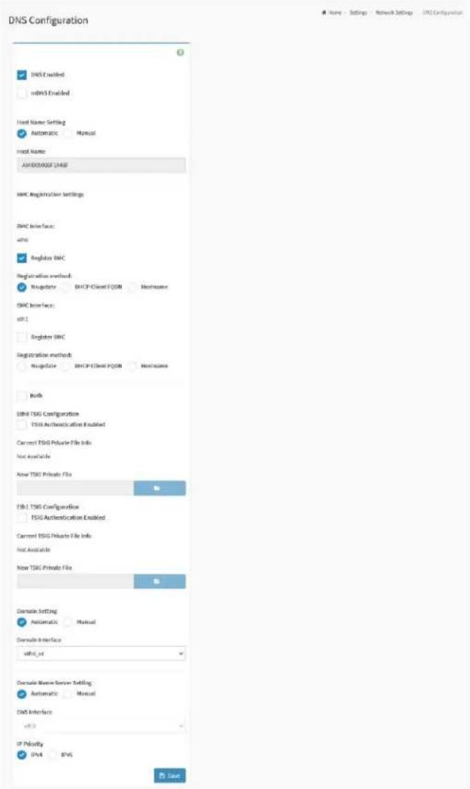
2.8.7.3 DNS Configuration
The Domain Name System (DNS) is a distributed hierarchical naming system for computers, services, or any resource connected to the Internet or a private network.
This page provides various options for users to configure the DNS Configuration settings.
To view the Network IP Settings page, click the Settings -> Network Settings -> DNS Configuration tab from the menu bar.
Figure 55. Snapshot of DNS Configuration Page
text_image
DNS Configuration ✓ DNS Enabled ✓ mbNS Enabled Host Name Setting ✓ Automatic Manual Host Name: AMODOMOS LANF BMC Registration Settings BMC Drive face: wb0 ✓ Regulator BMC Registration enabled: Regulator DHCP-Client FCOM Maintenance BMC Drive face: wb1 ✓ Register BMC Registration method: Regulator DHCP-Client FCOM Maintenance Both BMC TSG Configuration TSIG Authentication Enabled Current TSIG Private File Info Not Available New TSIG Private File CBL TSG Configuration TSIG Authentication Enabled Current TSIG Private File Info Not Available New TSIG Private File Domain Setting: Automatic Manual Domain Interface: wb0_wk Domain Manager Service Setting: Automatic Manual DNS Interface: wb0 IP Priority SPA IPVS SaveThe fields on the DNS Configuration page include
● DNS Enabled: Click this option to enable all DNS services.
● mDNS Enabled: Click this option to enable Multicast DNS services.
- Host Name Setting: Select either Automatic or Manual settings.
■ Automatic
■ Manual
- Host Name: Indicates Host Name of device. If Host Name Settings is Manual, specify the host name of device.
BMC Registration Settings:
- BMC Interface: Options to register the BMC through the Interface (Eth0 and Eth1).
Eth0 and Eth1:
- Register BMC: To register BMC through registration method.
- Registration method: Options to register the BMC through the below registration methods.
■ Nsupdate: Register with the DNS server using the nsupdate application.
■ DHCP Client FQDN: Register with the DNS server using DHCP option 81.
■ Hostname: Register with the DNS server using DHCP option 12.
Eth0 and Eth1 TSIG Configuration:
- Both: Click this option to modify TSIG authentication for both interfaces.
- TSIG Authentication Enabled: Click this option to enable TSIG authentication while registering DNS via nsupdate. Separate TSIG files can be uploaded for each LAN interface.
- Current TSIG Private File Info: The information of Current TSIG private file along with its up-loaded date/time will be displayed.
● New TSIG Private File: Browse and navigate to the TSIG private file.
- Domain Setting: Select whether the domain interface will be configured manually or automatically.
■ Automatic: If Automatic is selected, the Domain Name cannot be configured as it will be done automatically. The field will be disabled.
■ Manual: If Manual is selected, specify the domain name of the
device.
- Domain Interface: Indicates the domain name of the device.
● DNS Interface: Specify the interface to be used.
- IP Priority:
■ IPv4: If IPv4 is selected, it will have 2 IPv4 DNS servers and 1 IPv6 DNS server.
■ IPv6: If IPv6 is selected, it will have 2 IPv6 DNS servers and 1 IPv4 DNS server.
● DNS Server 1, 2, and 3: Specify the DNS server address to be configured for the BMC.
Note: IPv4 and IPv6 address format are supported.
- Save: To save the configured settings.
2.8.8 PAM Order Settings
Pluggable authentication module (PAM) is a mechanism to integrate multiple low-level authentication schemes into a high-level application programming interface (API).
PAM Order Settings page provides the options for users to configure the PAM ordering for user authentication in to the BMC.
To view the PAM Order Settings page, click the Settings -> PAM Order Settings tab from the menu bar.
Figure 56. Snapshot of PAM Order Settings Page
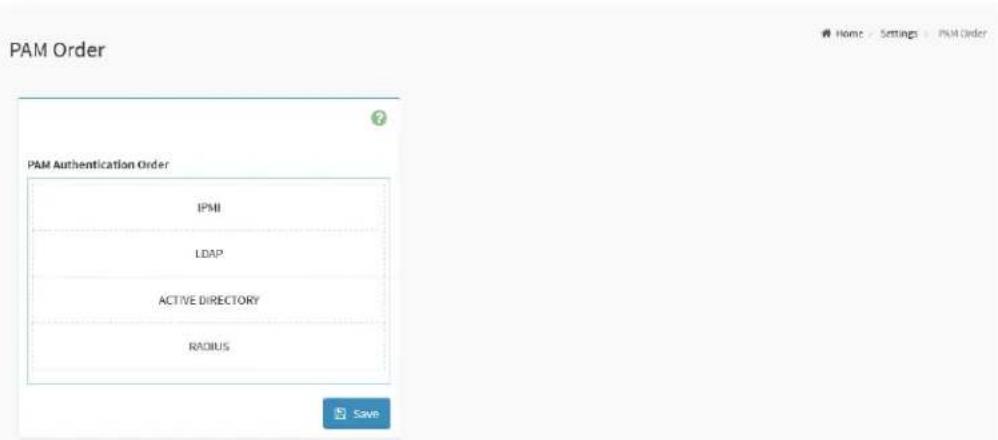
text_image
PAM Order PAM Authentication Order IPMI LDAP ACTIVE DIRECTORY RADIUS SaveThe fields on the PAM Order Settings page include
- PAM Module: lists the available PAM modules supported in the BMC. Select the required PAM module and click and drag the required PAM module. It can be moved UP or DOWN to change its arrangement order.
- Save: To save the configured settings.
2.8.9 Platform Event Filters
Platform Event Filter (PEF) provides a mechanism for configuring the BMC to take selected actions on event messages that it receives or has internally generated. These actions include operations such as system power-off, system reset, as well as triggering the generation of an alert.
Platform Event Filters page provides various functional feature tabs for users to configure the PEF feature, including
- Event Filters
- Alert Policies
• LAN Destinations
To view the Platform Event Filters page, click the Settings -> Platform Event Filters tab from the menu bar.
Figure 57. Snapshot of Platform Event Filters Page
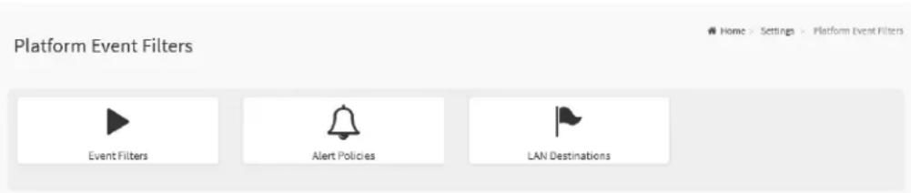
text_image
Platform Event Filters Event Filters Alert Policies LAN DestinationsThe details about each feature are listed in the following.
2.8.9.1 Event Filters
A PEF implementation is recommended to provide at least 40 entries in the event filter table. A subset of these entries should be pre-configured for common system failure events, such as over-temperature, power system failure, fan failure events,
To view the Event Filters page, click the Settings -> Platform Event Filters -> Event Filters tab from the menu bar.
Figure 58. Snapshot of Platform Event Filters Slot List Page
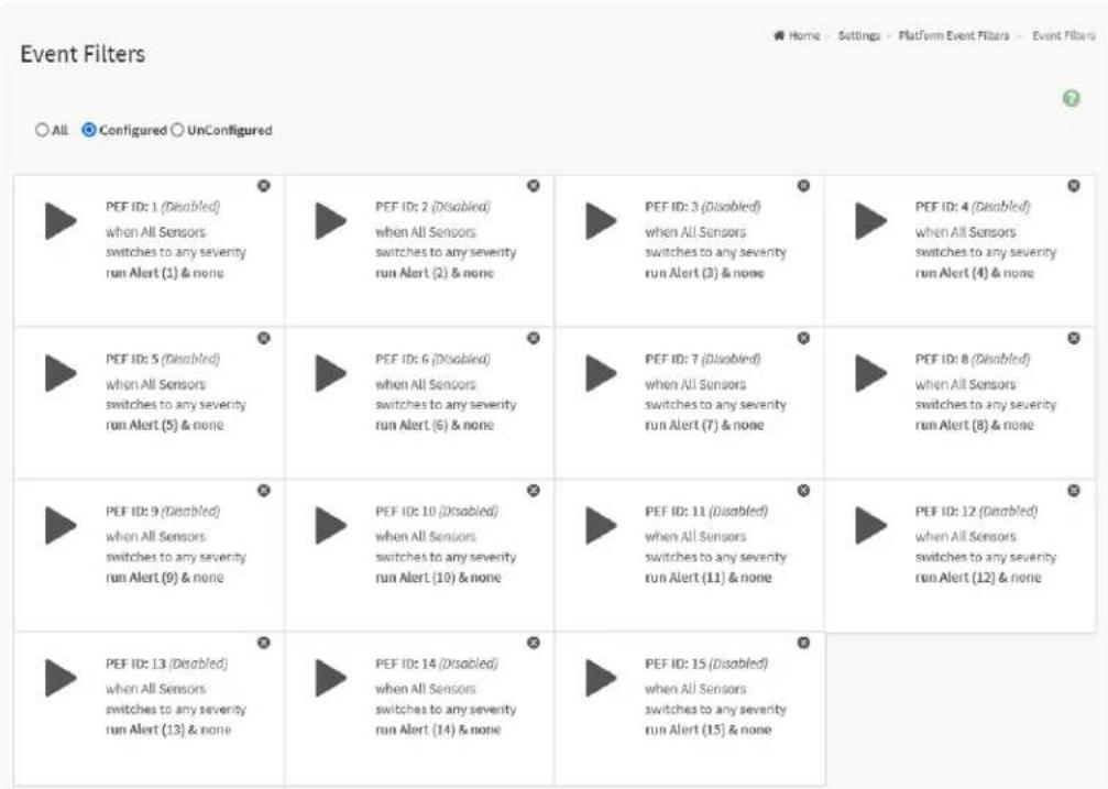
text_image
Event Filters All Configured UnConfigured PEF ID: 1 (Disabled) when All Sensors switches to any severity run Alert (1) & none PEF ID: 2 (Disabled) when All Sensors switches to any severity run Alert (2) & none PEF ID: 3 (Disabled) when All Sensors switches to any severity run Alert (3) & none PEF ID: 4 (Disabled) when All Sensors switches to any severity run Alert (4) & none PEF ID: 5 (Disabled) when All Sensors switches to any severity run Alert (5) & none PEF ID: 6 (Disabled) when All Sensors switches to any severity run Alert (6) & none PEF ID: 7 (Disabled) when All Sensors switches to any severity run Alert (7) & none PEF ID: 8 (Disabled) when All Sensors switches to any severity run Alert (8) & none PEF ID: 9 (Disabled) when All Sensors switches to any severity run Alert (9) & none PEF ID: 10 (Disabled) when All Sensors switches to any severity run Alert (10) & none PEF ID: 11 (Disabled) when All Sensors switches to any severity run Alert (11) & none PEF ID: 12 (Disabled) when All Sensors switches to any severity run Alert (12) & none PEF ID: 13 (Disabled) when All Sensors switches to any severity run Alert (13) & none PEF ID: 14 (Disabled) when All Sensors switches to any severity run Alert (14) & none PEF ID: 15 (Disabled) when All Sensors switches to any severity run Alert (15) & noneThe fields on the Event Filters page include
• All: Click this option to lists all slots.
- Configured: Click this option to lists all configured slots.
● Unconfigured: Click this option to lists all unconfigured slots.
Click on the Event Filters Slot icon ( ) then navigate to the Event Filter Configuration page.
Click on the Delete icon ( ) on the top right corner of Event Filters Slot to directly to delete a slot from the list.
Figure 59. Snapshot of Event Filters Configuration Page
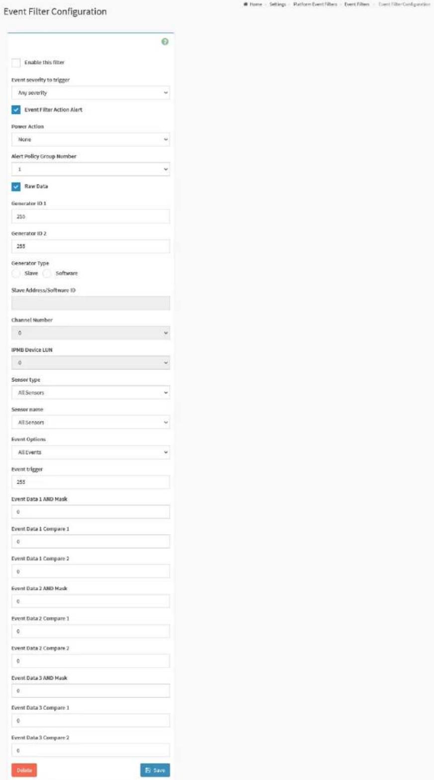
text_image
Event Filter Configuration Enable this filter Event severity to trigger Any severity Event Filter Action Alert Power Action None Alert Policy Group Number 1 Raw Data Generator ID 1 255 Generator ID 2 255 Generator Type Slave Software Slave Address/Software ID Channel Number 0 IPMB Device LUN 0 Sensor Type All Sensors Sensor name All Sensors Event Options All Events Event trigger 255 Event Data 1 AND Mask 0 Event Data 1 Compare 1 0 Event Data 1 Compare 2 0 Event Data 2 AND Mask 0 Event Data 2 Compare 1 0 Event Data 2 Compare 2 0 Event Data 3 AND Mask 0 Event Data 3 Compare 1 0 Event Data 3 Compare 2 0 Delete SaveThe fields on the Event Filters Configuration page include
- Enable this filter: Click this option to enable the PEF settings.
- Event severity to trigger: Select any one of the Event Severity from the drop-down list.
● Event Filter Action Alert: Click this option to enable PEF Alert action.
● Power Action: Select any one of the Power Action either Power down, Power reset or Power cycle from the drop-down list. - Alert Policy Group Number: Select any one of the configured Alert Policy Group Number from the drop-down list.
Note: Alert Policy has to be configured under Settings -> Platform Event Filters -> Alert Policies.
● Raw Data: Click this option to enter the Generator ID with raw data.
- Generator ID 1: Specify the raw generator ID1 data value.
- Generator ID 2: Specify the raw generator ID2 data value.
- Generator Type:
■ Slave: Select Slave if event was generated from IPMB.
■ Software: Select Software if event was generated from system software.
- Slave Address/Software ID: Specify corresponding I2C Slave Address or System Software ID.
- Channel Number: Select the particular channel number through which the event message is received over. Choose '0' if the event message is received via the system interface, primary IPMB, or internally generated by the BMC.
- IPMB Device LUN: Select the corresponding IPMB Device LUN if event is generated by IPMB.
- Sensor Type: Select the type of sensor that will trigger the event filter action.
- Sensor Name: Select the particular sensor from the sensor list.
- Event Options: Select event option to be either All events or Sensor specific events.
- Event Trigger: This field is used to give Event/Reading type value. Value ranges from 0 to 255.
- Event Data 1 AND Mask: This field is used to indicate wildcarded or compared bits. Value ranges from 0 to 255.
- Event Data 1 Compare 1: This field is used to indicate whether each bit position's comparison is an exact comparison or not.
- Event Data 1 Compare 2: This field is used to indicate whether each bit position's comparison is an exact comparison or not. Value ranges from 0 to 255.
- Event Data 2 AND Mask and Event Data 3 AND Mask: These fields are similar to Event Data 1 AND Mask.
- Event Data 2 Compare 1 and Event Data 3 Compare 1: These fields are similar to Event Data 1 Compare 1.
- Event Data 2 Compare 2 and Event Data 3 Compare 2: These fields are similar to Event Data 1 Compare 2.
- Delete: To delete the existing filter.
- Save: To save the configured settings.
2.8.9.2 Alert Policies
This page provides the feature for users to configure the Alert Policy for PEF configuration.
To view the Alter Policies page, click the Settings -> Platform Event Filters -> Alter Policies tab from the menu bar.
Figure 60. Snapshot of Alert Policies Page
| Group: 1 (Disabled) Always send alert to this destination LAN Channel: 1 Sent To: 0 | Group: 2 (Disabled) Always send alert to this destination LAN Channel: 1 Sent To: 0 | Group: 3 (Disabled) Always send alert to this destination LAN Channel: 1 Sent To: 0 | Group: 4 (Disabled) Always send alert to this destination LAN Channel: 1 Sent To: 0 |
| Group: 5 (Disabled) Always send alert to this destination LAN Channel: 1 Sent To: 0 | Group: 6 (Disabled) Always send alert to this destination LAN Channel: 1 Sent To: 0 | Group: 7 (Disabled) Always send alert to this destination LAN Channel: 1 Sent To: 0 | Group: 8 (Disabled) Always send alert to this destination LAN Channel: 1 Sent To: 0 |
| Group: 9 (Disabled) Always send alert to this destination LAN Channel: 1 Sent To: 0 | Group: 10 (Disabled) Always send alert to this destination LAN Channel: 1 Sent To: 0 | Group: 11 (Disabled) Always send alert to this destination LAN Channel: 1 Sent To: 0 | Group: 12 (Disabled) Always send alert to this destination LAN Channel: 1 Sent To: 0 |
| Group: 13 (Disabled) Always send alert to this destination LAN Channel: 1 Sent To: 0 | Group: 14 (Disabled) Always send alert to this destination LAN Channel: 1 Sent To: 0 | Group: 15 (Disabled) Always send alert to this destination LAN Channel: 1 Sent To: 0 | Group: 1 (Disabled) Always send alert to this destination LAN Channel: 1 Sent To: 0 |
| Group: 2 (Disabled) Always send alert to this destination LAN Channel: 1 Sent To: 0 | Group: 3 (Disabled) Always send alert to this destination LAN Channel: 1 Sent To: 0 | Group: 4 (Disabled) Always send alert to this destination LAN Channel: 1 Sent To: 0 | Group: 5 (Disabled) Always send alert to this destination LAN Channel: 1 Sent To: 0 |
| Group: 6 (Disabled) Always send alert to this destination LAN Channel: 1 Sent To: 0 | Group: 7 (Disabled) Always send alert to this destination LAN Channel: 1 Sent To: 0 | Group: 8 (Disabled) Always send alert to this destination LAN Channel: 1 Sent To: 0 | Group: 9 (Disabled) Always send alert to this destination LAN Channel: 1 Sent To: 0 |
| Group: 10 (Disabled) Always send alert to this destination LAN Channel: 1 Sent To: 0 | Group: 11 (Disabled) Always send alert to this destination LAN Channel: 1 Sent To: 0 | Group: 12 (Disabled) Always send alert to this destination LAN Channel: 1 Sent To: 0 | Group: 13 (Disabled) Always send alert to this destination LAN Channel: 1 Sent To: 0 |
Click on the Alert Policy Slot icon ( ) then navigate to the Alert Policies Configuration page.
Click on the Delete icon ( ) on the top right corner of Alert Policy Slot to directly to delete a slot from the list.
Figure 61. Snapshot of Alert Policies Configuration Page

text_image
Alert Policies Policy Group Number 1 Enable this alert Policy Action Always send alert to this destination LAN Channel 1 Destination Selector Event Specific Alert String Alert String Key Delete SaveThe fields on the Alert Policies Configuration page include
● Policy Group Number: Indicates the policy group number of the configuration.
● Enable this alert: Click this option to enable this alert policy.
● Policy Action: Select any one of the Policy Action set from the list.
● LAN Channel: Select a particular channel from the available channel list.
- Destination Selector: Select a particular destination from the configured destination list.
Note: LAN Destination has to be configured under Settings -> Platform Event Filters -> LAN Destinations.
● Event Specific Alert String: Specify an event-specific Alert String.
- Alert String Key: Specify which string is to be sent for this Alert Policy entry.
- Delete: To delete the configured Alter Policy.
- Save: To save the configured settings.
2.8.9.3 LAN Destinations
This page provides the feature for users to configure the LAN Destinations for PEF configuration.
To view the LAN Destinations page, click the Settings -> Platform Event Filters -> LAN Destinations tab from the menu bar.
Figure 62. Snapshot of LAN Destinations Page

text_image
LAN Destinations Select the LAN Channel 1 LAN Channel: 1 LAN Destination: 1 SNMP Trap Sent To: LAN Channel: 1 LAN Destination: 2 SNMP Trap Sent To: LAN Channel: 1 LAN Destination: 3 SNMP Trap Sent To: LAN Channel: 1 LAN Destination: 4 SNMP Trap Sent To: LAN Channel: 1 LAN Destination: 5 SNMP Trap Sent To: LAN Channel: 1 LAN Destination: 6 SNMP Trap Sent To: LAN Channel: 1 LAN Destination: 7 SNMP Trap Sent To: LAN Channel: 1 LAN Destination: 8 SNMP Trap Sent To: LAN Channel: 1 LAN Destination: 9 SNMP Trap Sent To: LAN Channel: 1 LAN Destination: 10 SNMP Trap Sent To: LAN Channel: 1 LAN Destination: 11 SNMP Trap Sent To: LAN Channel: 1 LAN Destination: 12 SNMP Trap Sent To:The fields on the LAN Destinations page include
- Select the LAN Channel: To select the LAN Channel number.
Click on the LAN Destination Slot icon (1) then navigate to the LAN Destination Configuration page.
Click on the Mail icon ( ) on the bottom right corner of LAN Destination Slot to send a test alert mail.
Figure 63. Snapshot of LAN Destinations Configuration Page
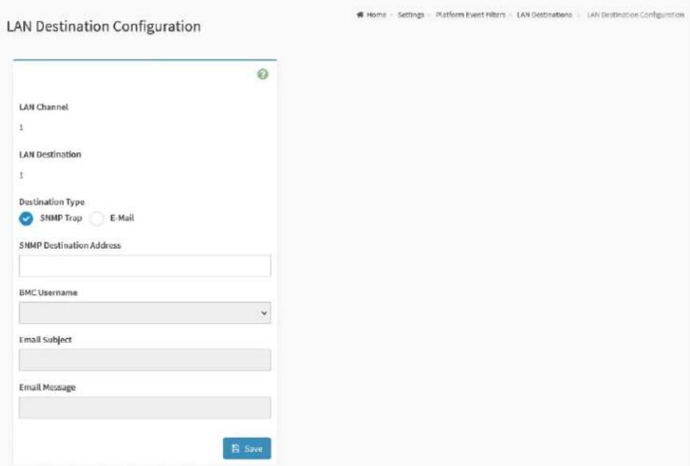
text_image
LAN Destination Configuration LAN Channel 1 LAN Destination 1 Destination Type ✓ SNMP Trap ○ E-Mail SNMP Destination Address BMC Username Email Subject Email Message SaveThe fields on the LAN Destinations Configuration page include
● LAN Channel: Indicates the LAN Channel Number of the selected slot
● LAN Destination: Indicates the Destination number of the selected slot
- Destination Type: Destination type can be either an SNMP Trap or an E-mail alert.
■ SNMP Trap: If SNMP Trap is selected, then give the IP address of the system that will receive the alert.
■ E-Mail: If E-Mail is selected, then choose the user to whom the email alert has to be sent.
- SNMP Destination Address: Specify the IP address of the system that will receive the alert. IPv4 and IPv6 IP address format are supported.
● BMC Username: Select the user to whom the email alert has to be sent. - Email Subject and Email Message: An email will be sent to the configured email address of the user in case of any severity events with a subject specified in subject field and will contain the message field's content as the email body.
NOTE: These fields are not applicable for 'AMI-Format' email users.
- Save: To save the configured settings.
2.8.10 Services
This page provides the information about services running in the BMC. Only administrator can modify the service.
To view the Services page, click the Settings -> Services tab from the menu bar.
Figure 64. Snapshot of Services Page
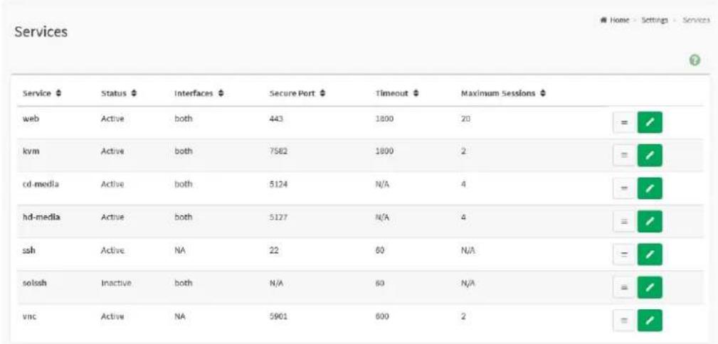
text_image
Services Service Status Interfaces Secure Port Timeout Maximum Sessions web Active both 443 1800 20 = # kvm Active both 7582 1800 2 = # cd-media Active both 5124 N/A 4 = # hd-media Active both 5127 N/A 4 = # ssh Active NA 22 60 N/A = # solssh Inactive both N/A 60 N/A = # vnc Active NA 5901 600 2 =/The fields on the Services page include
● Service: Indicates the service name of selected slot.
- Status: Indicates the current status of the service, either active or inactive state.
- Interfaces: Indicates the interface in which service is running.
- Secure Port: Indicates the secure port number for the service.
- Timeout: Indicates the session timeout value of the service.
● Maximum Session: Indicates the maximum number of allowed sessions for the service.
Click on the Edit icon (☐) then navigate to Service Configuration page to modify the services configuration.
Click on the View icon (°) then navigate to Service Sessions page to view or terminate the connected session for this service.
Figure 65. Snapshot of Services Configuration Page
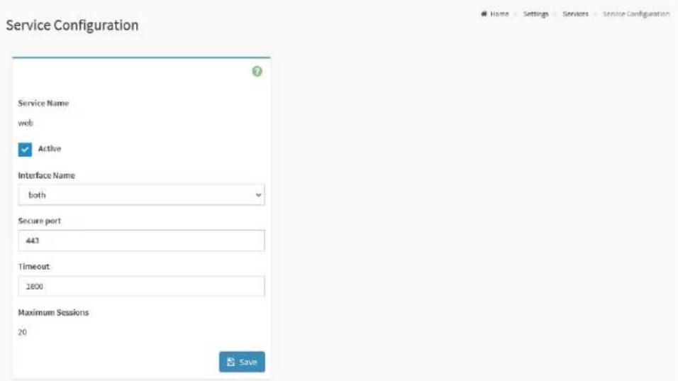
text_image
Service Configuration Service Name web ✓ Active Interface Name both Secure port 443 Timeout: 1800 Maximum Sessions 20 Home Settings Servicers Service Configuration SaveThe fields on the Services Configuration page include
● Service Name: Indicates the name of selected service.
● Active: Indicates the current status of the service, either active or inactive. Click this option to activate the service.
- Interface Name: Indicates the interface on which the service is running
- Secure port: Used to configure secure port numbers for the services.
- Timeout: Specify the timeout value.
● Maximum Sessions: Indicates the maximum number of allowed sessions for the service.
- Save: To save the configured settings.
Figure 66. Snapshot of Services Sessions Page
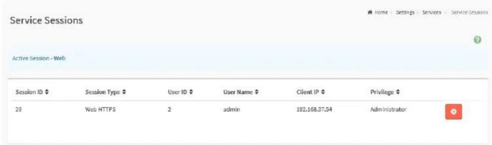
text_image
Service Sessions Active Session - Web Session ID ♦ Session Type ♦ User ID ♦ User Name ♦ Client IP ♦ Privilege ♦ 20 Web HTTPS 2 admin 192.168.37.54 AdministratorThe fields on the Services Sessions page include
- Session ID: Indicates the ID number of this session.
- Session Type: Indicates the type of the active sessions.
- User ID: Indicates the ID number of the user.
- User Name: Indicates the name of the user.
- Client IP: Indicates the IP addresses that are already configured for the active sessions.
- Privilege: Indicates the access privilege of the user.
Click on the Terminate icon ( ) to terminate the particular session of the service.
2.8.11 SMTP Settings
Simple Mail Transfer Protocol (SMTP) is an internet standard communication protocol for electronic mail transmission.
This page provides various options for users to configure the SMTP settings of the device.
To view the SMTP Settings page, click the Settings -> SMTP Settings tab from the menu bar.
Figure 67. Snapshot of SMTP Settings Page
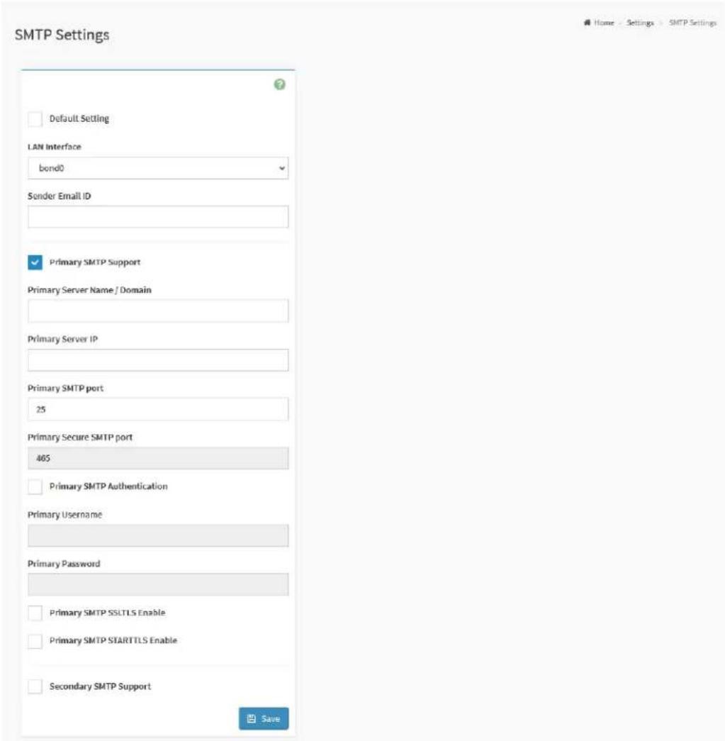
text_image
SMTP Settings Default Setting LAN Interface bond0 Sender Email ID Primary SMTP Support Primary Server Name / Domain Primary Server IP Primary SMTP port 25 Primary Secure SMTP port 405 Primary SMTP Authentication Primary Username Primary Password Primary SMTP SSLTLS Enable Primary SMTP STARTTLS Enable Secondary SMTP Support SaveThe fields on the SMTP Settings page include
- Default Setting: Click this option to enable all parameters use default values.
● LAN Interface: Indicates the list of LAN channels available. - Sender Email ID: To specify a valid 'Sender Email ID' on the SMTP Server.
Primary and Secondary SMTP Support:
- SMTP Support: Click this option to enable SMTP support for the BMC.
- Server Name / Domain: To specify the 'Machine Name' of the SMTP Server.
- Server IP: To specify the 'IP address' of the SMTP Server.
- SMTP port: To specify the SMTP Port.
- Secure SMTP port: To specify the SMTP Secure Port.
- SMTP Authentication: Click this option 'Enable' to enable SMTP Authentication.
- Username: To specify the username required to access SMTP Accounts.
- Password: To specify the password for the SMTP User Account.
- SMTP SSLTLS Enable: Click this option t enable the SMTP SSLTLS protocol.
- SMTP STARTTLS Enable: Click this option to enable the SMTP STARTTLS protocol.
■ Upload SMTP CA Certificate File: Use Browse button to navigate to upload CACERT. CACERT key file should be of pem type.
■ Upload SMTP Certificate File: Use Browse button to navigate to upload CERT. CERT key file should be of pem type.
■ Upload SMTP Private Key: Use Browse button to navigate to upload SMTP KEY. SMTP key file should be of pem type.
2.8.12 SSL Settings
The Secure Socket Layer (SSL) protocol is a networking protocol designed for securing connections between web clients and web servers over an insecure network. The protocol uses a third party, a Certificate Authority (CA), to identify one end or both end of the transactions.
SSL Settings page provides various functional feature tabs for users to monitor or configure the SSL settings value, including
• View SSL Certificate
- Generate SSL Certificate
- Upload SSL Certificate
To view the SSL Settings page, click the Settings -> SSL Settings tab from the menu bar.
Figure 68. Snapshot of SSL Settings Page

text_image
SSL Settings View SSL certificate Generate SSL certificate Upload SSL certificateThe details about each feature are listed in the following.
2.8.12.1 View SSL Certificate
This page provides the information of current certificate information.
To view the View SSL Certificate page, click the Settings -> SSL Settings -> View SSL Certificate tab from the menu bar.
Figure 69. Snapshot of View SSL Certificate Page

text_image
View SSL Certificate Current Certificate Information Certificate Version 3 Serial Number SAEC249338828C26BLA4675R2ES11BC9LA2B840 Signature Algorithm sha250WithRSAEncryption Public Key (2048 bit) Issuer Common Name (CN) megarac.com Issuer Organization (O) American Megatrends International LLC (AAH) Issuer Organization Unit (OU) Service Processors Issuer City or Locality (L) Neurox Issuer State or Province (ST) Georgia Issuer Country (C) US Issuer Email Address support@amr.com Valid From Mar 25 09:55:58 2022 GMT Valid Till Mar 22 09:55:58 2022 GMT Issued to Common Name (CN) megarac.com Issued to Organization (O) American Megatrends International LLC (AAH) Issued to Organization Unit (OU) Service Processors Issued to City or Locality (L) Noncross Issued to State or Province (ST) Georgia Issued to Country (C) US Issued to Email Address support@amr.comThe fields on the View SSL Certificate page include
Basic Information:
• Certificate Version
- Serial Number
• Signature Algorithm
- Public Key
Issued From:
- Issuer Common Name (CN)
- Issuer Organization (O)
- Issuer Organization Unit (OU)
- Issuer City or Locality (L)
- Issuer State or Province (ST)
- Issuer Country (C)
- Issuer Email Address
Validity Information:
- Valid From
- Valid Till
Issued To:
- Issued to Common Name (CN)
- Issued to Organization (O)
- Issued to Organization Unit (OU)
- Issued to City or Locality (L)
- Issued to State or Province (ST)
- Issued to Country (C)
- Issued to Email Address
2.8.12.2 Generate SSL Certificate
This page provides the various options for users to generate SSL certificate through the BMC Web service.
To view the Generate SSL Certificate page, click the Settings -> SSL
Settings -> Generate SSL Certificate tab from the menu bar.
Figure 70. Snapshot of Generate SSL Certificate Page

text_image
Generate SSL Certificate Common Name (CN) Organization (O) Organization Unit (OU) City or Locality (L) State or Province (ST) Country (C) Email Address Valid for In days Key Length 2048 bits SaveThe fields on the Generate SSL Certificate page include
- Common Name (CN): To specify the common name for which the certificate is to be generated.
- Organization (O): To specify the name of the organization for which certificate is to be generated.
- Organization Unit (OU): To specify the Section or Unit of the organization for which certificate is to be generated.
● City or Locality (L): To specify the City or Locality.
● State or Province (ST): To specify the State or Province.
● Country (C): To specify the Country code.
- Email Address: To specify the Email Address of the organization.
- Valid for: Requested validity days for the certificate.
● Key Length: Select the key length bit value of the certificate.
- Save: To save the configured settings.
2.8.12.3 Upload SSL Certificate
This page provides the various options for users to upload the new SSL Certificate file into the BMC to replace the old one.
To view the Upload SSL Certificate page, click the Settings -> SSL Settings -> Upload SSL Certificate tab from the menu bar.
Figure 71. Snapshot of Upload SSL Certificate Page

text_image
Upload SSL Certificate Current Certificate Fri Mar 25 09:55:58 2022 New Certificate Current Private Key Fri Mar 25 09:55:58 2022 New Private Key SaveThe fields on the Upload SSL Certificate page include
- Current Certificate: The information of the Current Certificate and date/time of its upload will be displayed (read-only).
- New Certificate: Browse and navigate to the new certificate file. Certificate file should be of pem type.
- Current Private Key: Information for the current private key and date/time when it was uploaded will be displayed (read-only).
- New Private Key: Browse and navigate to the private key file. Private Key file should be of pem type.
- Save: To save the configured settings.
2.8.13 System Firewall
System Firewall page provides various functional feature tabs for users to configure the firewall settings, including
- General Firewall Settings
- IP Firewall Rules
- Port Firewall Rules
To view the System Firewall page, click the Settings -> System Firewall tab from the menu bar.
Figure 72. Snapshot of System Firewall Page
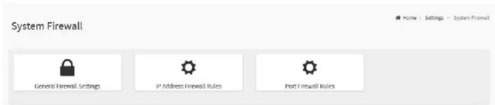
text_image
System Firewall General Firewall Settings IP Address Firewall Rules Port Firewall RulesThe details about each feature are listed in the following.
2.8.13.1 General Firewall Settings
This page provides various functional feature tabs for users to configure the General Firewall Settings and monitor the configured settings, including
- Existing Firewall Settings
- Add Firewall Settings
To view the General Firewall Settings page, click the Settings -> System Firewall -> General Firewall Settings tab from the menu bar.
Figure 73. Snapshot of General Firewall Settings Page
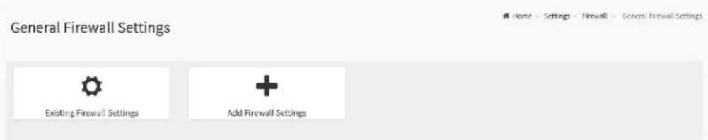
text_image
General Firewall Settings Existing Firewall Settings Add Firewall SettingsThe details about each feature are listed in the following.
2.8.13.1.1 Existing Firewall Settings
This page lists all configured General Firewall Settings instance. A blank page will be opened if users did not add any General Firewall Settings instance from Add Firewall Settings.
To view the Existing Firewall Settings page, click the Settings -> System Firewall -> General Firewall Settings -> Existing Firewall Settings tab from the menu bar.
Figure 74. Snapshot of Existing Firewall Settings Page of General Firewall Settings

text_image
Existing Firewall Settings Block All: IPv4 Timeout: Enabled From: Sun May 01 2022 16:00:00 To: Sun May 01 2022 16:15:00 Block All: IPv6 Timeout: Enabled From: Sun May 01 2022 13:00:00 To: Sun May 01 2022 13:15:00 Block All: IPv6 Timeout: Enabled From: Sun May 01 2022 12:00:00 To: Sun May 01 2022 12:15:00Click on the Slot icon ( ) then navigate to instance page. Click on the Delete icon ( ) then delete this slot.
Figure 75. Snapshot of Existing Firewall Settings Instance Page of General Firewall Settings

text_image
Existing Firewall Settings Block All IPv4 Flush All Timeout Start Date&Time Sun May 01 2022 16:00:00 End Date&Time Sun May 01 2022 16:15:00 DeleteThe fields on the Existing Firmware Settings instance page include
- Block All: This option will block all incoming IPs and Ports.
- Flush All: This option is used to flush all existing system firewall rules.
- Timeout: This field indicates the firewall rules whether with timeout feature.
- Start Date&Time: The firewall rule will become effective from this date.
- End Date&Time: The firewall rule will expire on this date.
- Delete: Click this button to delete this instance.
2.8.13.1.2 Add Firewall Settings
This page provides various options for users to add General Firewall Settings instance.
To view the Add Firewall Settings page, click the Settings -> System
Firewall -> General Firewall Settings -> Add Firewall Settings tab from the menu bar.
Figure 76. Snapshot of Add Firewall Settings page of General Firewall Settings

text_image
Add Firewall Settings Block All IPv4 Flush All Timeout Start Date YYYYMM/DD Start Time End Date YYYYMM/DD End Time SaveThe fields on the Add Firmware Settings page include
- Block All: Select the protocol and block all the incoming IP's and Port's.
- Flush All: To flush all the system firewall settings.
- Timeout: Click this option to enable or disable firewall rules with timeout.
- Start Date: To specify a Start Date to start respective firewall rule effect from the date.
- Start Time: To specify a Start Time to start respective firewall rule effect from the Time.
- End Date: To specify an End Date to end respective firewall rule effect from the date.
● End Time: To specify a End Time to End respective firewall rule effect
from the Time.
- Save: To save the configured settings.
2.8.13.2 IP Firewall Rules
This page provides various functional feature tabs for users to configure the IP Firewall Rules and monitor the configured settings, including
- Existing IP Rules
- Add New IP Rule
To view the IP Firewall Rules page, click the Settings -> System Firewall -> IP Address Firewall Rules tab from the menu bar.
Figure 77. Snapshot of IP Firewall Rules Page
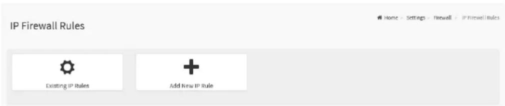
text_image
IP Firewall Rules Existing IP Rules Add New IP RuleThe details about each feature are listed in the following.
2.8.13.2.1 Existing IP Rules
This page lists all configured IP Firewall Rules instances. A blank page will be opened if users did not add any IP Firewall Rules instance from Add New IP Rule.
To view the Existing IP Rules page, click the Settings -> System Firewall -> IP Address Firewall Rules -> Existing IP Rules tab from the menu bar.
Figure 78. Snapshot of Existing IP Rules Page
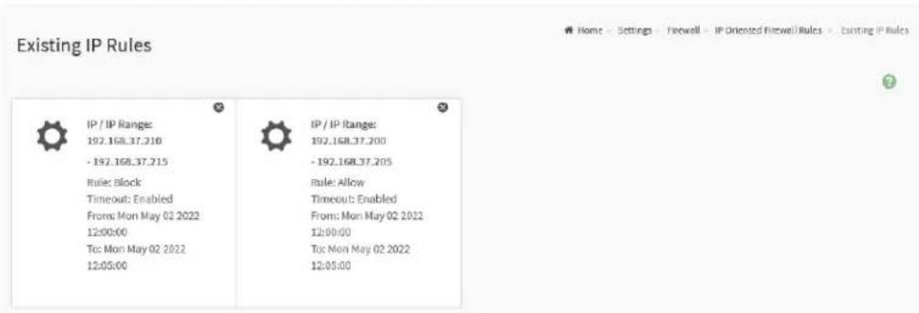
text_image
Existing IP Rules IP / IP Range: 192.168.37.210 - 192.168.37.215 Rule: Block Timeout: Enabled From: Mon May 02 2022 12:00:00 To: Mon May 02 2022 12:05:00 IP / IP Range: 192.168.37.200 - 192.168.37.205 Rule: Allow Timeout: Enabled From: Mon May 02 2022 12:00:00 To: Mon May 02 2022 12:05:00Click on the Slot icon ( ) then navigate to instance page. Click on the Delete icon ( ) then delete this slot.
Figure 79. Snapshot of Existing IP Rules Instance Page of IP Firewall Rules
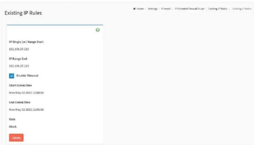
text_image
Existing IP Rules IP Single (or) Range Start 192.168.37.210 IP Range End 192.168.37.215 Enable Timeout Start Date& Time Mon May 02 2022 12:00:00 End Date& Time Mon May 02 2022 12:05:00 Rule Block DeleteThe fields on the Existing IP Rules instance page include
- IP Single (or) Range Start: This field indicates IP Address or the start of a Range of IP Addresses
- IP Range End: This field indicates the end of a Range of IP Addresses
- Enable Timeout: This field indicates the firewall rules whether with timeout feature.
- Start Date&Time: The respective firewall rule effect will start from this date and time.
- End Date&Time: The respective firewall rule effect will end from this date and time.
- Rule: This field indicates the current setting of the listed IP or Range of IP rules (Allow or Block).
- Delete: Click this button to delete this instance.
2.8.13.2.2 Add New IP Rule
This page provides various options for users to add IP Firewall Rule instance.
To view the Add New IP Rule page, click the Settings -> System Firewall -> IP Address Firewall Rules -> Add New IP Rule tab from the menu bar.
Figure 80. Snapshot of Add IP Rules Instance Page of IP Firewall Rules
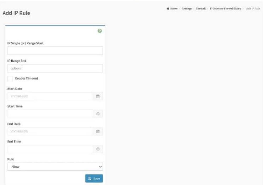
text_image
Add IP Rule IP Single (or) Range Start IP Range End optional Enable Timeout Start Date YYYYMM/DD Start Time End Date YYYYMM/DD End Time Rule Allow SaveThe fields on the Add IP Rule instance page include
- IP Single (or) Range Start: To specify an IP Address or the start of a Range of IP Addresses. IP Address must follow the IPv4 Address format:
- IP Range End: To specify an end of an IP address range.
- Enable Timeout: To enabled or disable Timeout.
- Start Date: The respective firewall rule effect will start from this date.
- Start Time: The respective firewall rule effect will start from this time.
● End Date: The respective firewall rule effect will end from this date.
● End Time: The respective firewall rule effect will end from this time. - Rule: To indicate the current setting of the listed IP Address or Range of IP Addressed rules (Allow or Block) status.
- Save: To save the configured settings.
2.8.13.3 Port Firewall Rules
This page provides various functional feature tabs for users to configure the Port Firewall Rules and monitor the configured settings, including
- Existing Port Rules
- Add New Port Rule
To view the IP Firewall Rules page, click the Settings -> System Firewall -> Port Firewall Rules tab from the menu bar.
Figure 81. Snapshot of Port Firewall Rules Page
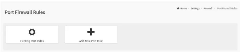
text_image
Port Firewall Rules Existing Port Rules Add New Port RuleThe details about each feature are listed in the following.
2.8.13.3.1 Existing Port Rules
This page lists all configured Port Firewall Rules instances. A blank page will be opened if users did not add any Port Firewall Rules instance from Add New Port Rule.
To view the Existing Port Rules page, click the Settings -> System Firewall -> Port Firewall Rules -> Existing Port Rules tab from the menu bar.
Figure 82. Snapshot of Existing Port Rules Page

text_image
Existing Port Rules Port / Port Range: 10100 -10200 Protocol: TCP Network Type: IPv4 Block: Timeout: Enabled From: Sun May 01 2022 12:00:00 To: Sun May 01 2022 12:15:00 Port / Port Range: 10000 -10010 Protocol: TCP Network Type: IPv4 Allow Timeout: Enabled From: Sun May 01 2022 12:00:00 To: Sun May 01 2022 12:15:00Click on the Slot icon ( ) then navigate to instance page. Click on the Delete icon ( ) then delete this slot.
Figure 83. Snapshot of Existing Port Rules Instance Page of Port Firewall Rules
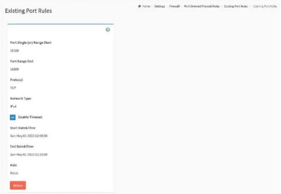
text_image
Existing Port Rules Port Single (or) Range Start 10100 Port Range End 10200 Protocol TCP Network Type IPv4 Enable Timeout Start Date&Time Sun May 01 2022 12:00:00 End Date&Time Sun May 01 2022 12:15:00 Rule Block DeleteThe fields on the Existing Port Rules instance page include
- Port Single (or) Range Start: This field indicates the port number or the start of range or port numbers.
● Port Range End: This field indicates the end of range or port numbers. - Protocol: This field indicates the protocols for the configured port or range or ports.
- Network Type: this field indicates the affected network type for the configured port or range of port numbers.
- Enable Timeout: This field indicates the firewall rules whether with timeout feature.
- Start Date&Time: The respective firewall rule effect will start from this date and time.
- End Date&Time: The respective firewall rule effect will end from this date and time.
- Rule: To indicate Allow or Block status.
- Delete: Click this button to delete this instance.
2.8.13.3.2 Add New Port Rule
This page provides various options for users to add Port Firewall Rule instance.
To view the Add New Port Rule page, click the Settings -> System Firewall -> Port Firewall Rules -> Add New Port Rule tab from the menu bar.
Figure 84. Snapshot of Add Port Rules Instance Page of Port Firewall Rules

text_image
Add Port Rule Port Single (or) Range Start Port Range End optional Protocol TCP Network Type IPv4 Enable Timeout Start Date YYYY/00/00 Start Time End Date YYYY/MM/00 End Time Rule Allow SaveThe fields on the Add Port Rule instance page include
- Port Single (or) Range Start: To specify the port number or start of a range of port numbers.
● Port Range End: To specify the end of a range of port numbers. - Protocol: To select the protocol for the configured port or port ranges.
● Network Type: To select the affected network type for the configured port or port ranges. -
Enable Timeout: Click this option to enabled or disabled timeout.
-
Start Date: The respective firewall rule effect will start from this date.
- Start Time: The respective firewall rule effect will start from this time.
● End Date: The respective firewall rule effect will end from this date.
● End Time: The respective firewall rule effect will end from this time. - Rule: To indicate Allow or Block status.
- Save: To save the configured settings.
2.8.14 User Management
User Management page provides various options for users to view the current list of user slots for the BMC, and allow users to add a new user and modify or delete existing user.
To view the User Management page, click the Settings -> User Management tab from the menu bar.
Figure 85. Snapshot of User Management Page

text_image
User Management Channel 1 Channel 1 1 anonymous (Disabled) No Access KVM VMware Channel 1 2 admin (Enabled) Administrator KVM VMware Channel 1 3 Administrator (Enabled) Administrator Channel 1 4 (Disabled) Channel 1 5 (Disabled) Channel 1 6 (Disabled) Channel 1 7 (Disabled) Channel 1 8 (Disabled) Channel 1 9 (Disabled) Channel 1 10 (Disabled) Channel 1 11 (Disabled) Channel 1 12 (Disabled) Channel 1 13 (Disabled) Channel 1 14 (Disabled) Channel 1 15 (Disabled)Channel 1 for users connect to BMC through dedicated IPMI LAN port.
Channel 8 for users connect to BMC through Share NIC LAN port.
Click on the User icon () then navigate to User Management Configuration page.
Click on the Delete icon ( ) then delete this slot.
Figure 86. Snapshot of User Management Configuration Page
User Management Configuration
Home - Settings - User Management - User Management Configuration

text_image
Username Password Size 16 bytes Password Confirm Password Password End date Current valid date age (days) Enable User Access Enable Channel Access Channel 1 Channel II Privilege(Channel 1) User Privileges(Channel 8) User KVM Access VMedia Access SNMP Access SNMP Access level SNMP Authentication Protocol SNMP Privacy Protocol Email Format Email ID Existing SSH Key Not Available Upload SSH Key SaveThe fields on the User Management Configuration page include
- Username: To specify a name for the user.
- Password Size: To select the preferred size for the password.
- Password: Password field is mandatory and should meet the password policy requirements.
- Confirm Password: Entering the password again to confirm the password.
- Password age (days): Enable and set the maximum password age.
● End date: To select the date for the expired date of password age.
● Current valid date: To indicate valid date of current. - Enable User Access: Click this option to enable this user account to access the BMC service.
- Enable Channel Access: To select the channel/channels to enable the network access for the user.
■ Channel 1: Allow user to access the BMC service through dedicated IPMI LAN port.
■ Channel 8: Allow user to access the BMC service through Share NIC LAN port. - Privilege (Channel 1) and Privilege (Channel 8): Select the privilege level for each channel to be assigned to this user for access to the BMC through the network interface. There are 5 levels of Network Privileges (Administrator, Operator, User, OEM and None).
● KVM Access: Click this option to assign the KVM privilege for the user. - VMedia Access: Click this option to assign the VMedia privilege for the user.
- SNMP Access: Click this option to assign the SNMP privilege for the user.
- SNMP Access level: To select the SNMP access level for the user.
- SNMP Authentication Protocol: To select the Authentication Protocol for the user.
- SNMP Privacy Protocol: To select the Encryption algorithm to be used for the SNMP settings.
- Email Format: To specify the format for the email
- Email ID: To specify the email ID for the user.
- Existing SSH Key: If available, the uploaded SSH key information will be displayed.
-
Upload SSH Key: Use Browse button to navigate to the new public SSH key file.
-
Delete: Click Delete button to delete this user account.
- Save: To save the configured settings.
2.8.15 Video Recording
Video Recording page provides the functional feature tab for users to configure the video recording settings, including
- Auto Video Settings
To view the Video Recording page, click the Settings -> Video Recording tab from the menu bar.
Figure 87. Snapshot of Video Recording Page

text_image
Video Recording Home - Settings - Video Recording Auto Video SettingsThe details about each feature are listed in the following.
2.8.15.1 Auto Video Settings
This page provides various functional feature tabs for users to configure the events that will trigger auto video recording function of the KVM server, including
• Video Trigger Settings
• Video Remote Storage
● Pre-Event Video Recordings
To view the Auto Video Recording page, click the Settings -> Video
Recording -> Auto Video Settings tab from the menu bar.
Figure 88. Snapshot of Auto Video Recording Page

text_image
Auto Video Settings Video Trigger Settings Video Remote Storage Pre-Event Video RecordingsThe details about each feature are listed in the following.
2.8.15.1.1 Video Trigger Settings
This page provides various options for users to configure the video trigger settings.
To view the Video Trigger Settings page, click the Settings -> Video Recording -> Auto Video Settings -> Video Trigger Settings tab from the menu bar.
Figure 89. Snapshot of Video Trigger Settings Page
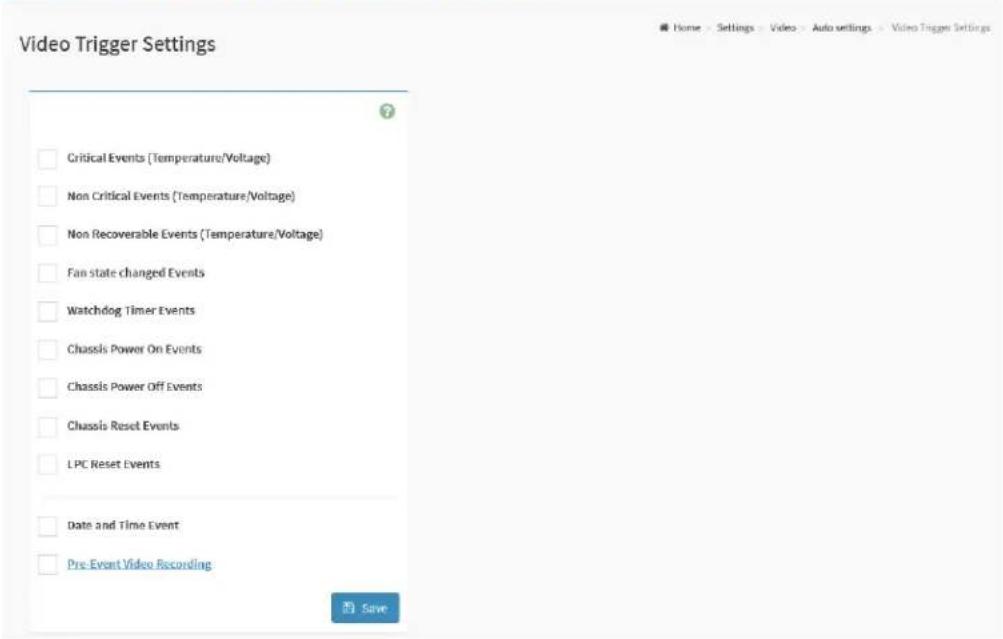
text_image
Video Trigger Settings Critical Events (Temperature/Voltage) Non Critical Events (Temperature/Voltage) Non Recoverable Events (Temperature/Voltage) Fan state changed Events Watchdog Timer Events Chassis Power On Events Chassis Power Off Events Chassis Reset Events LPC Reset Events Date and Time Event Pre-Event Video Recording SaveThe fields on the Video Trigger Settings page include
● Critical Events (Temperature/Voltage)
● Non-Critical Events (Temperature/Voltage)
• Non-Recoverable Events (Temperature/Voltage)
● Fan state changed Events
- Watchdog Timer Events
- Chassis Power-On Events
- Chassis Power-Off Events
- Chassis Reset Events
- LPC Reset Events
● Date and Time Event
• Pre-Event Video Recording
- Crash Reset
■ Pre-crash
■ Pre-reset
- Save: To save the configured settings.
2.8.15.1.2 Video Remote Storage
This page provides various options for users to configure the video remote storage settings, which for save the capture video file to the remote server.
To view the Video Remote Storage page, click the Settings -> Video Recording -> Auto Video Settings -> Video Remote Storage tab from the menu bar.
Figure 90. Snapshot of Video Remote Storage Page
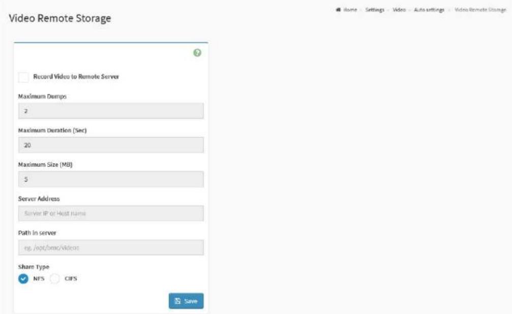
text_image
Video Remote Storage Record Video to Remote Server Maximum Damps 2 Maximum Duration (Sec) 20 Maximum Size (MB) 5 Server Address Server IP or Host Name Path in server es /opt/bmc/videos Share Type NFS CIFS SaveThe fields on the Video Remote Storage page include
- Record Video to Remote Server: Click this option to enable Remote Video support.
● Maximum Dumps: To specify the number of Maximum Dumps, range from 1 to 100.
● Maximum Duration (Sec): To specify the number of Maximum Duration, range from 1 to 3600 seconds.
● Maximum Size (MB): To specify the number of Maximum size, range from 1 to 500 MB. - Server Address: Address of the server where remote videos are to be stored. IP Address and FQDN format are supported.
- Path in server: To specify the path in the remote server.
- Share Type: To select Share Type of the remote video server
■ NFS
CIFS
- Save: To save the configured settings.
2.8.15.1.3 Pre-Event Video Recordings
This page provides various options for users to configure Pre-Event video recording
To view the Video Remote Storage page, click the Settings -> Video Recording -> Auto Video Settings -> Pre-Event Video Recordings tab from the menu bar.
Figure 91. Snapshot of Pre-Event Video Recordings Page

text_image
Pre-Event Video Recordings This page is used to configure the Pre-Event video recording options. Pre-Event video recording is disabled by default. To enable the Pre-Event video recording, go to the Triggers Configuration page. Video Quality Very Low Compression Mode High Frames Per Second 1 Video Duration 10 SaveThe fields on the Pre-Event Video Recordings page include
- Video Quality: To select the desired video quality from the options in the drop-down list.
- Compression Mode: To select the Compression Mode from the options listed in the drop-down list.
- Frames Per Second: To select the FPS to specify the desired number of frames per second.
● Video Duration: To select the desired video duration in seconds. - Save: To save the configured settings.
2.8.16 IPMI Interfaces
IPMI Interfaces page provides various options for users to configure the IPMI communication interface settings.
To view the IPMI Interfaces page, click the Settings -> IPMI Interfaces tab from the menu bar.
Figure 92. Snapshot of IPMI Interfaces Page
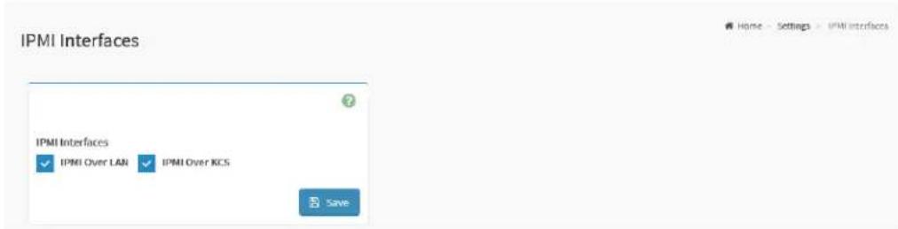
text_image
IPMI Interfaces IPMI Interfaces ✓ IPMI Over LAN ✓ IPMI Over ICS SaveThe fields on the IPMI Interfaces page include
- IPMI Interfaces: To select the interface which allow users to perform the IPMI communication.
■ IPMI Over LAN: Click this option to allows the IPMI communication over LAN.
■ IPMI Over KCS: Click this option to allows the IPMI communication over KCS.
- Save: To save the configured settings.
2.8.17 Keep Share NIC Link Up
This page provides the option for users to configure the share NIC PHY link up settings.
To view the Keep Share NIC Link Up page, click the Settings -> Keep Share NIC Link Up tab from the menu bar.
Figure 93. Snapshot of Keep Share NIC Link Up Page

text_image
Keep Share NIC Link Up Keep Share NIC Link Up Enable saveThe fields on the Keep Share NIC Link Up page include
- Enabled: Click this option to enable Keep Share NIC Link Up supported. If enabled feature, the Share NIC PHY will keep link up, and it could avoid the share NIC link disconnection while system reset.
- Save: To save the configured settings.
2.8.18 FAN Settings
FAN Settings page provides various functional feature tabs for users to configure the system FAN settings which control by the BMC, including
- Open Loop Control Table
- Close Loop Control Table
● Temperature Sensor and Corresponding Fan Table - FAN Mode
To view the FAN Settings page, click the Settings -> FAN Settings tab from the menu bar.
Figure 94. Snapshot of FAN Settings Page

text_image
FAN Settings Open Loop Control Table Close Loop Control Table Temperature Sensor and Corresponding Fan Table FAN ModeThe details about each feature are listed in the following.
2.8.18.1 Open Loop Control Table
This page provides various options for users to configure the Open Loop Control Table settings, users can add the new FAN table from Temperature Sensor and Corresponding Fan Table
To view the Open Loop Control Table FAN page, click the Settings -> FAN Settings -> Open Loop Control Table FAN tab from the menu bar.
Figure 95. Snapshot of Open Loop Control Table Page

text_image
Open Loop Control Table Control Table Table 1 Entry Temp (°C) Duty (%) Entry Temp (°C) Duty % 1 2 3 4 5 6 7 8 9 10 11 12 Clear SaveThe fields on the Open Loop Control Table page include
● Control Table: To select the table which to be used.
• Entry: Indicates the condition number.
- Temp (°C): To specify the temperature for this entry.
● Duty (%): To specify the FAN duty for this entry.
- Default: Click Default button to loading the default setting value of selected table.
- Customized: Click the Customized button to modify the settings value for selected table.
- Clear: To clear current settings value on the web.
- Save: To save the configured settings.
2.8.18.2 Close Loop Control Table
This page provides various options for users to configure the Close Loop Control Table settings, users can add the new FAN table from Temperature Sensor and Corresponding Fan Table
To view the Open Loop Control Table FAN page, click the Settings -> FAN Settings -> Close Loop Control Table FAN tab from the menu bar.
Figure 96. Snapshot of Close Loop Control Table Page

text_image
Close Loop Control Table Table Table 1 Ramp Temperature (°C) Ramp Rate (%) Ramp Delay (sec.) Slew Temperature (°C) Slew Rate (%) Slew Delay (sec.) Clear SaveThe fields on the Close Loop Control Table page include
● Table: To select the table which to be used.
- Ramp Temperature (°C): To specify the value for Ramp Temperature.
● Ramp Rate (%): To specify the value for Ramp Rate.
● Ramp Delay (sec.): To specify the value for Ramp Delay.
- Slew Temperature (°C): To specify the value for Slew Temperature.
● Slew Rate (%): To specify the value for Slew Rate.
- Slew Delay (sec.): To specify the value for Slew Delay.
- Default: Click Default button to loading the default setting value of selected table.
- Customized: Click the Customized button to modify the settings value
for selected table.
- Clear: To clear current settings value on the web.
- Save: To save the configured settings.
2.8.18.3 Temperature Sensor and Corresponding Fan Table
This page provides various options for users to configure the temperature sensor and FAN table settings for Open Loop Control Table and Close Loop Control Table use.
To view the Temperature Sensor and Corresponding Fan Table page, click the Settings -> FAN Settings -> Temperature Sensor and Corresponding Fan Table tab from the menu bar.
Figure 97. Snapshot of Temperature Sensor and Corresponding Fan Table Page
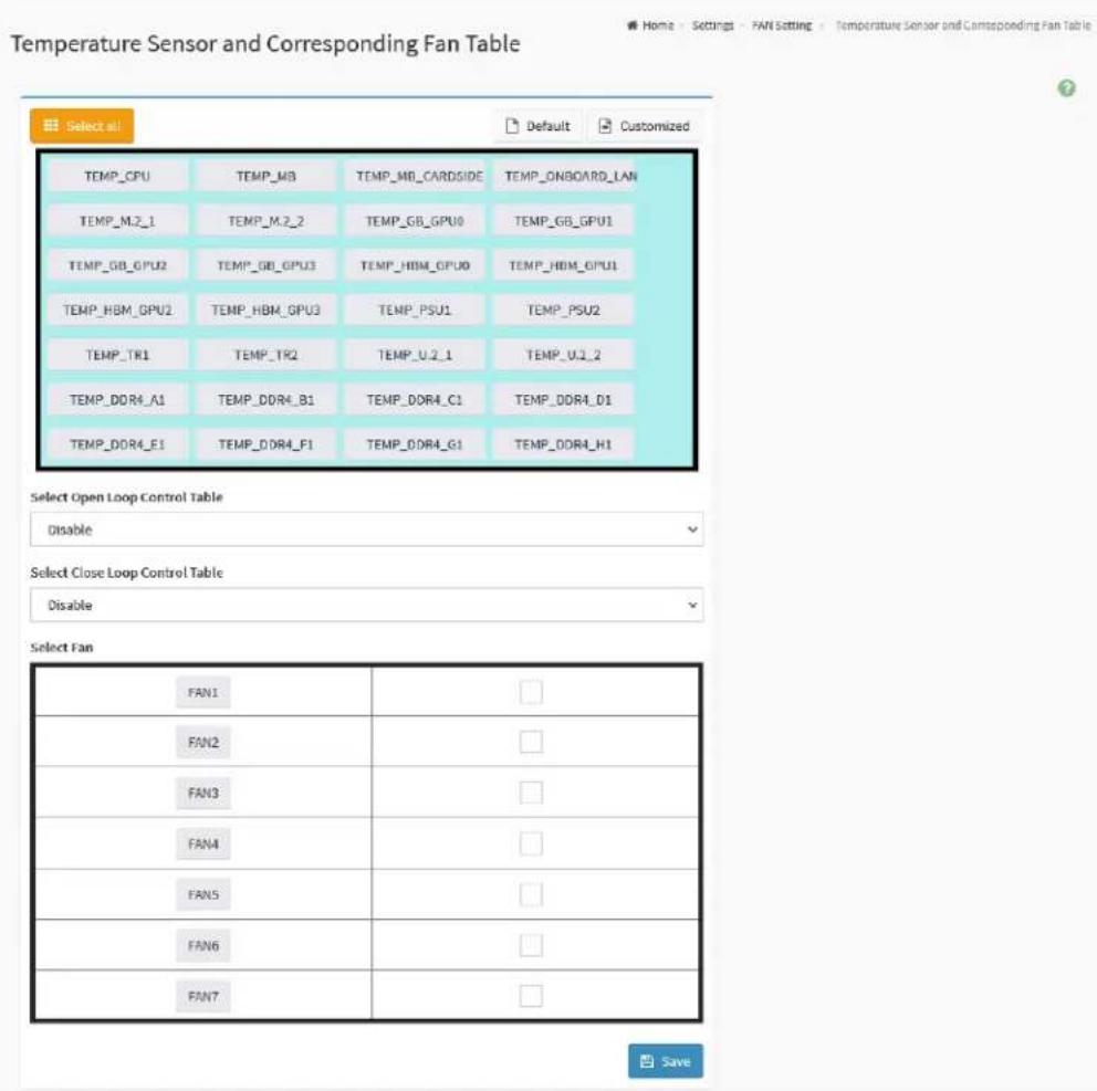
text_image
Temperature Sensor and Corresponding Fan Table Select all Default Customized TEMP_CPU TEMP_MB TEMP_MB_CARDSIDE TEMP_ONBOARD_LAN TEMP_M.2_1 TEMP_M.2_2 TEMP_GB_GPU TEMP_GB_GPU TEMP_GB_GPU TEMP_GB_GPU TEMP_HBM_GPU TEMP_HBM_GPU TEMP_HBM_GPU TEMP_HBM_GPU TEMP_PSU TEMP_PSU2 TEMP_TR1 TEMP_TR2 TEMP_U.2_1 TEMP_U.2_2 TEMP_DDR4_A1 TEMP_DDR4_B1 TEMP_DDR4_C1 TEMP_DDR4_D1 TEMP_DDR4_E1 TEMP_DDR4_F1 TEMP_DDR4_G1 TEMP_DDR4_H1 Select Open Loop Control Table Disable Select Close Loop Control Table Disable Select Fan FAN1 FAN2 FAN3 FAN4 FAN5 FAN6 FAN7 SaveThe fields on the Temperature Sensor and Corresponding Fan Table page include
- Select Open Loop Control Table: To select the Open Loop Control
Table which to be used.
- Select Close Loop Control Table: To select the Close Loop Control Table which to be used.
- Select Fan: To select the FAN which affect in the selected table.
- Select All: Click this button to select all sensors in the sensor list.
- Default: Click Default button to loading the default setting value (the default selected FAN) of selected temperature sensor.
- Customized: Click the Customized button to modify the settings value for the selected FAN.
- Save: To save the configured settings.
2.8.18.4 FAN Mode
This page provides various options for users to configure the fan control mode settings, including control mode and fan duty for manual mode.
To view the FAN Mode page, click the Settings -> FAN Settings -> FAN Mode tab from the menu bar.
Figure 98. Snapshot of FAN Mode Page

text_image
FAN Mode Enable FAN duty 100% during BH update. Fan Duty For Manual Mode FAN Duty (%) FAN1 30 FAN2 30 FAN3 30 FAN4 30 FAN5 30 FAN6 30 FAN7 30 Fan Control Mode Mode Default Manual Customized FAN1 ✓ □ □ FAN2 ✓ □ □ FAN3 ✓ □ □ FAN4 ✓ □ □ FAN5 ✓ □ □ FAN6 ✓ □ □ FANT ✓ □ □ ★ Clear All Fan Setting Save control modeThe fields on the FAN Mode page include
- Enable FAN duty 100% during BM update: Click this option to enable this feature.
● Fan Duty For Manual Mode: To specify the fan duty value for the
specific FAN while runs in manual mode.
● Fan Control Mode: To select the fan control mode.
- Clear All Fan Setting: Click Clear All Fan Setting button to clear current setting value.
- Save Control Mode: Click Save Control Mode button to save the configured settings.
2.8.19 Power Restore Policy
Power Restore Policy page provides various options for users to configure the power restore policy settings.
To view the Power Restore Policy page, click the Settings -> Power Restore Policy tab from the menu bar.
Figure 99. Snapshot of Power Restore Policy Page

text_image
Power Restore Policy Power Restore Policy Always off Restore last state Always On SaveThe fields on the Power Restore Policy page include
● Always off: After the power is restored, the system will remain off.
- Restore last state: Restore the system to the same state as before the power failure
● Always On: After the power is restored, the system will automatically power-on.
- Save: To save the configured settings.
2.8.20 Password Settings
Password Settings page provides various settings for users to configure the password policy.
To view the Password Settings page, click the Settings -> Password Settings tab from the menu bar.
Figure 100. Snapshot of Password Settings Page

text_image
Password Settings Password Settings Maximum retry count 0 Attempted count reset interval (minutes) 0 Account lockout interval (minutes) 10 Minimum length 8 Complexity Lower Case Upper Case Number Special Character SaveThe fields on the Password Settings page include
● Maximum retry count: Click this option to enable this feature. To specify the value for Maximum Retry Count, and user will be locked out if number of failed login attempt reach this setting.
- Attempted count reset interval (minutes): Click this option to enable this feature. To specify the value for the interval value to reset attempted failure count.
- Account lockout interval (minutes): Click this option to enable this feature. To specify the value for unlock user after the interval if the user has been locked out.
● Minimum length: Set the minimum password length.
● Complexity: Click the options for enhance the password strength.
■ Lower Case: Password must have lower case character.
■ Upper Case: Password must have upper case character.
■ Number: Password must have number.
■ Special Character: Password must have special character.
- Save: To save the configured settings.
2.9 Remote Control
BMC service provides two useful remote control services named H5Viewer and JViewer, which allows users to remote control the host through the KVM service runs on either HTML5 web interface or Java Runtime Environment (JRE) interface.
Remote Control page provides two functional feature tabs for users to launch the remote KVM service.
To view the Remote Control page, click the Remote Control tab from the menu bar.
Figure 101. Snapshot of Remote Control Page
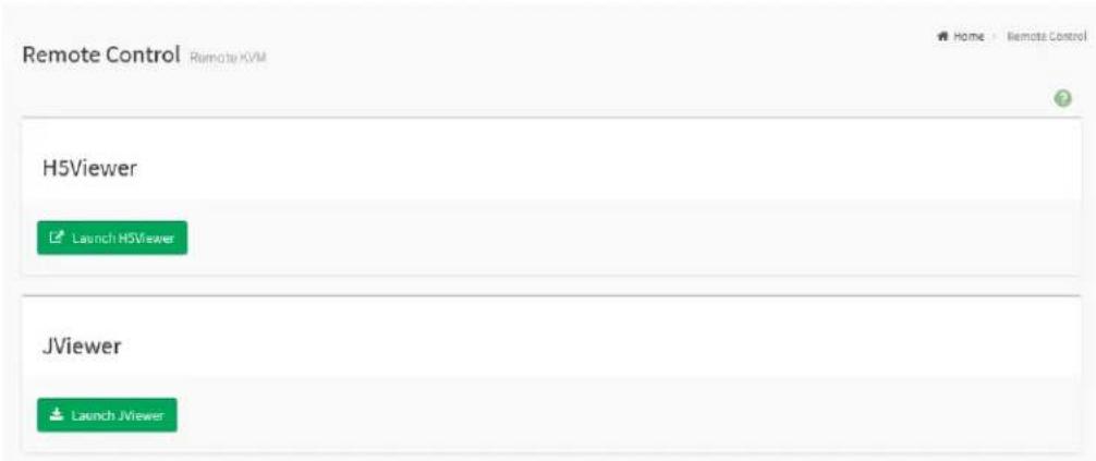
text_image
Remote Control Remote HVM H5Viewer Launch H5Viewer JViewer Launch JViewerThe fields on the Remote Control page include
- Launch H5Viewer: Click Launch H5Viewer button to open the H5Viewer web KVM page.
- Launch JViewer: Click Launch JViewer button to download the JRE KVM executable file.
The details about each feature are listed in the following.
2.9.1 H5Viewer
H5Viewer provides a remote KVM service for users to remote control the host through the HTML5 environment.
To view the J5Viewerl page, click the Settings -> Remote Control -> Launch H5Viewer button from the menu bar.
Figure 102. Snapshot of H5Viewer KVM Page

text_image
Stop KVM Video Mouse Options Keyboard Send Keys Hot Keys Video Record Power Active Users Help Aptio Setup Utility - Copyright (C) 2022 American Megatrends, Inc. Main Advanced Server Hgmt Security Boot Event Logs Exit AMD FBS Option UEFI Version : ROMED8-2T L3.32 DMC Version : 3.16.00 Processor Type : AMD EPVC 7742 64-Core Processor Processor Speed : 2262MHz Microcode Update : 830F10/83010=0 L1 Instruction Cache : 52KB L1 Data Cache Size : 52KB L2 Cache Size : 512KB L3 Cache per Socket : 256MB Total Memory : 64GB DDR4_A1 : None DDR4_B1 : 64GB RDIMM (DDR4-3200) DDR4_C1 : None DDR4_D1 : None DDR4_E1 : None DDR4_F1 : None DDR4_G1 : None DDR4_H1 : None System Date [Thu 05/05/2022] System Time [08:18:22] Set the Date. Use Tab to switch between Date elements. Default Ranges: Year: 2005-2095 Months: 1-12 Days: dependent on month +: Select Screen TL: Select Item Enter: Select +/-: Change Option F1: General Help F7: Discard Changes F9: Load UEFI Defaults F10: Save and Exit ESC: Exit Version 2.30.1275. Copyright (C) 2022 American Megatrends, Inc. IWIN RWIN LAIT LCTRL RAIT RCTRL NUM CAPS SCRThe fields on the H5Viewer KVM page include
Video Menu
● Pause Video: Click this button to pausing the Console Redirection.
- Resume Video: Click this button to resume the Console Redirection when the session is paused.
- Refresh Video: Click this button to update the display shown in the Console Redirection window.
- Host Display
■ Display On: Click this button to enable this feature. The host
display will be turn on if this feature is enabled.
■ Display Off: Click this button to enable this feature. The host display will be blank if this feature is enabled, but users can view the host screen in the Console Redirection window.
- Capture Screen: Click this button to take a screenshot of the host screen and save it in the client system.
Mouse Menu
- Show Client Cursor: Click this button to show or hide the local mouse cursor on the remote client system.
- Mouse Mode: This option handles mouse emulation from local window to remote screen using below methods. Only Administrator has the privilege to configure this option.
■ Absolute Mouse Mode: The absolute position of the local mouse is sent to the server if this option is selected.
■ Relative Mouse Mode: The Relative mode sends the calculated relative mouse position displacement to the server if this option is selected.
■ Other Mouse Mode: This mouse mode sets the client cursor in the middle of the client system and will send the deviation to the host. This mouse mode is specific for SUSE Linux installation.
Option Menu
- Zone
■ Normal: Click this button to set the screen size to default size.
■ Zoom In: Click this button to increasing the screen size. This zoom varies from 100% to 150% with an interval of 10%.
■ Zoom Out: Click this button to decreasing the screen size. This zoom varies from 100% to 50% with an interval of 10%.
- Block Privilege Request: To enable or disable the access privilege for the user.
■ Partial Permission
■ No Permission
● Band Width: Select the band width for the Console Redirection window
■ Auto Detect
■ 256Kbps
■ 512Kbps
- Compression Mode: This option helps to compress the video data transfer to the specific mode.
■ YUV 420
■ YUV 444
■ YUV 444 + 2 color VQ
■ YUV 444 + 4 color VQ
- DTC Quantization Table: This option helps to select the video quality.
■ 0 Best Quality
■ 1
■ 2
■ 3
4
■ 5
6
Keyboard Menu
- Keyboard Layout: This feature is fully compatible when host and client has the same keyboard language layout. If the client and host language layouts differ, some special characters will not be compatible.
■ English U.S
German
■ Japanese
- Virtual Keyboard: Click this button to open a virtual keyboard on the Console Redirection window.
Send Keys Menu
- Hold Down
■ Right Ctrl Key: Click this button to act as hold down the right-side
■ Right Alt Key: Click this button to act as hold down the right-side
■ Right Windows Key: Click this button to act as hold down the right-side
■ Left Ctrl Key: Click this button to act as hold down the left-side
■ Left Alt Key: Click this button to act as hold down the left-side
■ Left Windows Key: Click this button to act as hold down the left-side
- Press and Release
- Ctrl+Alt+Del: Click this button to act as single hit the
, and keys down simultaneously on the host that user is redirecting.
■ Left Windows Key: Click this button to act as single hit the left-sidekey when in Console Redirection.
■ Right Windows Key: Click this button to act as single hit the right-sidekey when in Console Redirection.
■ Context Menu Key: Click this button to act as single hit the context menu key when in Console Redirection.
■ Print Screen Key: Click this button to act as single hit the print screen key when in Console Redirection.
Hot Keys Menu
- Add Hot Keys: Click this button to open the User Define Macros window to add the hot key macro. The configured key events are saved in the BMC.
Video Record Menu
- Record Video: Click this button to start recording the screen.
- Stop Recording: Click this button to stop the recording.
- Record Settings: Click this button to open the Record Settings window to configure the settings.
■ Video Length: To specify the value for video length, range of 1 to 1800 seconds.
■ Video Compression: To specify the value for video compression, range of 0.1 (low image quality) to 0.9 (high image quality).
■ Normalized video resolution to 1024 X 768: Enable this feature that host video will be scaled to 1024 x 768 in the recorded video file.
■ OK: Click this button to save the configured settings.
■ Cancel: Click this button to leave this window without save the
settings.
Power Menu
- Reset Server: To reboot the system without powering off (warm boot).
- Immediate Shutdown: To perform Power OFF Immediately.
- Orderly Shutdown: To Power OFF the sever in proper order.
● Power On Server: To Power ON the server. - Power Cycle Server: To first power off, and then reboot the system (cold boot).
Active Users Menu
- Click this option to display the active users and their system IP address.
Help Menu
- Click this option to get more information About H5Viewer. The KVM Remote Console utility version and plugin version will be displayed.
Quick Buttons
● : This quick button will show/hide notifications dropdown menu, which will contain the list of notifications displayed by H5Viewer.
- : This quick button indicates the current zoom value in percentage.
- : This quick button indicates the current host monitor status. If the icon is in green color then host monitor is unlocked. If the icon is in red color then host monitor is locked. Clicking the button to change the monitor status.
- : This quick button indicates the current server power status. If the icon is in green color, the server power status is powered on. If the icon is in red color, the server power status is powered off. Click this button to toggle immediate power off/power on the host.
- : Click this button to close current KVM session and Console Redirection window.
CD Image: Browse.File (0 KB)
● : Click the Browse File button to select the
image file, then remote mounting the image file to the host.
- : Click the Media Boost button to boost up the image mount process.
Start Media
- : Click the Start Media button to start remote mount the image file.
Stop Media
- : Click the Stop Media button to stop remote mount the image file.
Status Bar Buttons
- : Num/Caps/Scroll lock buttons are LED status buttons that denotes the current status of Num/Caps/Scroll lock in the host.
2.9.2 JViewer
This is an OS independent plug-in which can be used in Windows as well as Linux with the help of JRE. JRE should be installed in the client's system.
To download the J5Viewerl executable file, click the Remote Control -> Launch JViewer button from the menu bar.
Figure 103. Snapshot of JViewer KVM Application
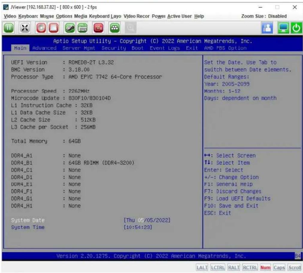
text_image
JViewer [192.168.37.82] - [ 800 x 600 ] - 2 fps Video Keyboard Mouse Options Media Keyboard Layo Video Recor Power Active User Help Zoom Size: Disabled Aptio Setup Utility - Copyright (C) 2022 American Megatrends, Inc. Main Advanced Server Mgmt Security Boot Event Logs Exit AMD PBS Option UEFI Version : ROMED8-2T L3.32 BMC Version : 3.18.00 Processor Type : AMD EPYC 7742 64-Core Processor Processor Speed : 2262MHz Microcode Update : 830F10/830104D L1 Instruction Cache : 32KB L1 Data Cache Size : 32KB L2 Cache Size : 512KB L3 Cache per Socket : 256MB Total Memory : 64GB DDR4_A1 : None DDR4_B1 : 64GB RDIMM (DDR4-3200) DDR4_C1 : None DDR4_D1 : None DDR4_E1 : None DDR4_F1 : None DDR4_G1 : None DDR4_H1 : None System Date [Thu 05/05/2022] System Time [10:54:23] Set the Date. Use Tab to switch between Date elements. Default Ranges: Year: 2005-2099 Months: 1-12 Days: dependent on month +: Select Screen ↑↓: Select Item Enter: Select +/-: Change Option F1: General Help F7: Discard Changes F9: Load UEFI Defaults F10: Save and Exit ESC: Exit Version 2.20.1275. Copyright (C) 2022 American Megatrends, Inc. LALT LCTRL RALT RCTRL Num Caps ScrollThe fields on the JViewer KVM application include
Video Menu
- Pause Redirection: Click this button to pausing the Console Redirection.
- Resume Redirection: Click this button to resume the Console Redirection when the session is paused.
- Refresh Video: Click this button to update the display shown in the
Console Redirection window.
- Turn ON Host Display: Click this button to enable this feature. The host display will be turn on if this feature is enabled.
- Turn OFF Host Display: Click this button to enable this feature. The host display will be blank if this feature is enabled, but users can view the host screen in the Console Redirection window.
● Capture Screen: Click this button to take a screenshot of the host screen and save it in the client system.
- Full Screen: Click this button to view the Console Redirection in full screen mode (Maximize).
- Compression Mode: This option helps to compress the video data transfer to the specific mode.
■ YUV 420
■ YUV 444
■ YUV 444 + 2 color VQ
■ YUV 444 + 4 color VQ
- DTC Quantization Table: This option helps to select the video quality.
■ 0 Best Quality
- Exit: Click this button to exit the Console Redirection screen.
Keyboard Menu
- Hold Right Ctrl Key: Click this button to act as hold down the right-side
- Hold Right Alt Key: Click this button to act as hold down the right-side
- Hold Left Ctrl Key: Click this button to act as hold down the left-side
- Hold Left Alt Key: Click this button to act as hold down the left-side
- Left Windows Key: Click this button to act as the left-side
■ Hold Down
■ Press and Release
- Right Windows Key: Click this button to act as the right-side
■ Hold Down
■ Press and Release
- Ctrl+Alt+Del: Click this button to act as single hit the keys down simultaneously on the host that user is redirecting.
- Context Menu Key: Click this button to act as single hit the context menu key when in Console Redirection.
- Hot Key
■ Add Hot Keys: Click this button to open the User Define Macros window to add the hot key macro. The configured key events are saved in the BMC.
- Full Keyboard Support: Enable this option to provide full keyboard support. This option is used to trigger the Ctrl and Alt key directly to host from the physical keyboard.
Mouse Menu
- Show Cursor: Click this button to show or hide the local mouse cursor on the remote client system.
- Mouse Calibration: This option can be used only if the mouse mode is relative.
- Mouse Mode: This option handles mouse emulation from local window to remote screen using below methods. Only Administrator has the privilege to configure this option.
■ Absolute Mouse Mode: The absolute position of the local mouse is sent to the server if this option is selected.
■ Relative Mouse Mode: The Relative mode sends the calculated relative mouse position displacement to the server if this option is selected.
■ Other Mouse Mode: This mouse mode sets the client cursor in the middle of the client system and will send the deviation to the host. This mouse mode is specific for SUSE Linux installation.
Option Menu
- Band Width: Select the band width for the Console Redirection window
■ Zoom In: Click this button to increasing the screen size. This zoom varies from 100% to 150% with an interval of 10%.
■ Zoom Out: Click this button to decreasing the screen size. This zoom varies from 100% to 50% with an interval of 10%.
■ Actual Size: Click this button to set the screen size to default size.
■ Fit to Client Resolution: If the host screen resolution is greater than the client screen resolution, choose this option to fit the host screen to client screen.
■ Fit to Host Resolution: If the host screen resolution is lesser than the client screen resolution, choose this option to resize the JViewer frame to the host resolution.
- Send IPMI Command: Click this button to opens the IPMI Command Dialog window, users can enter the raw IPMI command in Hexadecimal field as hexadecimal value and click Send. The response will be displayed on the IPMI Command Dialog window.
- GUI Language: To select the desired GUI language.
■ cn - [CN]
■ English - [EN]
■ français - [FR]
- Block Privilege Request: To enable or disable the access privilege for the user.
■ Allow Only Video
■ Deny Access
Media Menu
- Virtual Media Wizard...: Click this button to open the Virtual Media window.
Figure 104. Snapshot of Virtual Media Application

text_image
Virtual Media CD/DVD Hard Disk/USB Connection Status Device Instances CD/DVD Media : I CD Image Browse Connect CD/DVD Redirection Status Device Instance Target Device Instance Source Image/Drive Bytes Read Redirection Mode CD/DVD Media : 1 Not Connected Not Connected Not Connected Not ConnectedThe virtual media application will allow users to redirect different media to the host system. The application supports CD/DVD, Hard Disk/USB devices as well as image files.
Keyboard Layout Menu
● Auto Detect: This option is used to detect keyboard layout automatically.
• Physical Keyboard
■ Host Platform: This feature contains two options Windows and Linux.
■ List of Host Physical Keyboard languages supported:
◆ English -US
◆ English – UK
◆ French
◆ French (Belgium)
♦ German (Germany)
♦ German (Switzerland)
◆ Japanese
♦ Spanish
Italian
Danish
♦ Finnish
◆ Norwegian (Norway)
◆ Portuguese (Portugal)
◆ Swedish
♦ Dutch (Netherland)
◆ Dutch (Belgium)
♦ Turkish - F
♦ Turkish - Q
- SoftKeyboard: This option allows user to select the keyboard layout. It will show the dialog as similar to Windows On-screen keyboard. If the client and host languages are different, user can select the soft keyboard that corresponds to the host keyboard layout from the list shown in JViewer, and use it to avoid typo errors.
■ List of Soft Physical Keyboard languages supported:
◆ English -US
◆ English - UK
♦ Spanish
French
♦ German (Germany)
Italian
Danish
♦ Finnish
♦ German (Switzerland)
♦ Norwegian (Norway)
◆ Portuguese (Portugal)
◆ Swedish
Hebrew
◆ French (Belgium)
◆ Dutch (Netherland)
♦ Dutch (Belgium)
◆ Russian (Russia)
◆ Japanese (QWERTY)
◆ Japanese (Hiragana)
◆ Japanese (Katakana)
♦ Turkish - F
♦ Turkish - Q
Video Record Menu
- Start Record: Click this button to start recording the screen.
- Stop Record: Click this button to stop the recording.
- Record Settings: Click this button to open the Record Settings window to configure the settings.
Figure 105. Snapshot of Video Record Window

text_image
Video Record Video Length 20 Seconds Video to be Saved C:\Users\Curtis_Chen Browse OK ✓ Normalized video resolution to 1024 X 768. This might reduce the video quality! Cancel■ Video Length: To specify the value for video length.
■ Video to be Saved: To specify the location where to save the video file.
■ Normalized video resolution to 1024 X 768: Enable this feature that host video will be scaled to 1024 x 768 in the recorded video file.
■ OK: Click this button to save the configured settings.
■ Cancel: Click this button to leave this window without save the settings.
Power Menu
- Reset Server: To reboot the system without powering off (warm boot).
-
Immediate Shutdown: To perform Power OFF Immediately.
-
Orderly Shutdown: To Power OFF the sever in proper order.
● Power On Server: To Power ON the server.
● Power Cycle Server: To first power off, and then reboot the system (cold boot).
Active Users Menu
- Click this option to display the active users and their system IP address.
Help Menu
- Click this option to get more information About JViewer. The KVM Remote Console utility version and plugin version will be displayed.
Quick Buttons
- : This quick button is used to play the Console Redirection after being pause.
- : This quick button is used to pausing the Console Redirection.
● : This quick button is used to view the Console Redirection in full screen mode. - : This quick button is used to open the CD/DVD window of Virtual Media application.
- : This quick button is used to open the Hard Disk/USB window of Virtual Media application.
- : This quick button is used to show or hide the mouse cursor on the remote client system.
- : This quick button is used to open a soft keyboard on the Console Redirection window.
● : This quick button is used to start video record.
● : This quick button is used to displays the available hotkeys.
● : This quick button indicates the active users.
- : This quick button indicates the current host monitor status. If the icon is in green color then host monitor is unlocked. If the icon is in red color then host monitor is locked. Clicking the button to change the monitor status.
- This quick button indicates the current server power status. If the icon is in green color, the server power status is powered on. If the icon is in red color, the server power status is powered off. Click this button to toggle immediate power off/power on the host.
Status Bar Buttons
● : Num/Caps/Scroll lock buttons are
LED status buttons that denotes the current status of Num/Caps/Scroll lock in the host.
2.10 Image Redirection
Image Redirection page provides the functional feature tab for user to configure the image into BMC for redirection.
To view the Image Redirection page, click the Image Redirection tab from the menu bar.
Figure 106. Snapshot of Image Redirection Page

text_image
Image Redirection Remote ImagesThe details about each feature are listed in the following.
2.10.1 Remote Images
Remote Images page provides various options for users to view the configured images on BMC.
To view the Remote Images page, click the Image Redirection -> Remote Images tab from the menu bar.
Figure 107. Snapshot of Remote Images Page
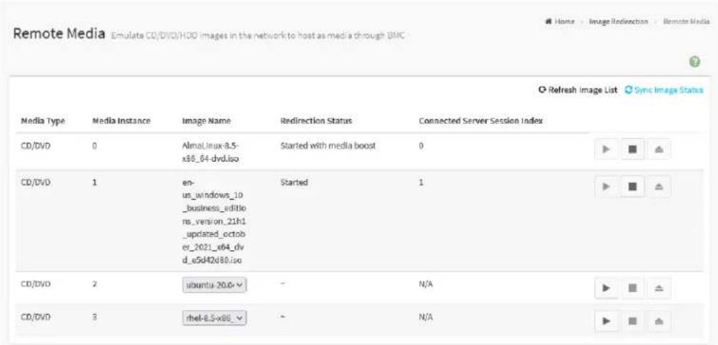
text_image
Remote Media Emulate CD/DVD/HDD images in the network to host as media through BMC Media Type Media Instance Image Name Redirection Status Connected Server Session Index CD/DVD 0 AlmaLinux-8.5-x86_04-dyd.iso Started with media boost 0 CD/DVD 1 en-us_windows_10_business_editions_version_21h1_updated_october_2021_x64_dvd_e5d42d80.iso Started 1 CD/DVD 2 ubuntu-20.6 - N/A CD/DVD 3 rmet-8.5-x86 - N/AThe fields on the Remote Images page include
● Media Type: The type Media devices supported for Active Redirections.
● Media Instance: The number of Media devices supported for Active Redirections.
- Image Name: The name of Media devices supported image for Active Redirections.
- Redirection Status: The status Media for Active Redirections.
- Connected Server Session Index: Indicates the number of connected server session index.
● Play: Click Play (▶) button to redirect the selected image.
- Stop: Click Stop ( ■ ) button to stop the remote image redirection.
- Clear: Click Clear ( ≈ ) button to clear the selected image from the BMC.
- Refresh Image List: Click Refresh Image List (Q) to get the latest list of Images from the Remote storage server.
- Sync Image Status: Click Sync Image Status (✗) to Turn on/off the redirection status of Images from the BMC.
2.11 Power Control
Power Control page provides various options for users to view and configure the power state of host.
To view the Power Control page, click the Power Control tab from the menu bar.
Figure 108. Snapshot of Power Control Page

text_image
Power Control on Host Server Power Actions Host is currently off Power Off Power On Power Cycle Hard Reset ACPI Shutdown Perform ActionThe fields on the Power Control page include
● Power Off: To immediately power off the host.
● Power On: To power on the host.
- Power Cycle: To select this option, the host will first power off, and then reboot the host (cold boot).
● Hard Reset: To reboot the host without powering off (warm boot).
- ACPI Shutdown: To initiate operating system shutdown prior to the shutdown.
● Perform Action: To executing the selected power policy.
2.12 Miscellaneous
Miscellaneous page provides various functional feature tabs for users to configure and monitor the server, including
- UID Control
- Post Snoop
To view the Miscellaneous page, click the Miscellaneous tab from the menu bar.
Figure 109. Snapshot of Miscellaneous Page

text_image
Miscellaneous UID Control Post SnoopThe details about each feature are listed in the following.
2.12.1 UID Control
UID Control page provides various options for users to configure UID LED, which is used to identify the host location.
To view the UID Control page, click the Miscellaneous -> UID Control tab from the menu bar.
Figure 110. Snapshot of UID Control Page
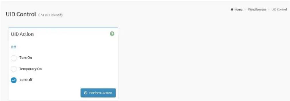
text_image
UID Control Chassis Identify UID Action Off Turn On Temporary On Turn Off Perform ActionThe fields on the UID Control page include
- UID Action
■ Status: Indicates current UID status.
- Turn On: To turn on UID LED.
- Temporary On: To temporary turn on UID LED (15 sec blink).
- Turn Off: To turn off UID LED.
- Perform Action: Click Perform Action button to executing selected UID action.
2.12.2 Post Snoop
Post Snoop page provides the feature for users to view the latest BIOS POST code which snooped by BMC.
To view the Post Snoop page, click the Miscellaneous -> Post Snoop tab from the menu bar.
Figure 111. Snapshot of Post Snoop Page

text_image
Post Snoop POST Code Port 80h: e015 RefreshThe fields on the Post Snoop page include
● Port 80h: Indicates the latest BIOS POST code.
- Refresh: Click Refresh button to updates the latest BIOS POST code.
2.13 Maintenance
Maintenance page provides various functional feature for users to do maintenance task on the device, including
- Backup Configuration
- Firmware Image Location
- Firmware Update
- BIOS Update
- PSU Update
- FPGA Update
- Re-timer Update
- Backplane Update
- CPLD Update
- Preserve Configuration
- Restore Configuration
- Restore Factory Defaults
- Reset
To view the Maintenance page, click the Maintenance tab from the menu bar.
Figure 112. Snapshot of Maintenance Page
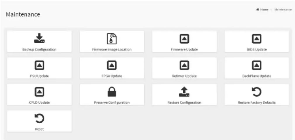
text_image
Maintenance Backup Configuration Firmware Image Location Firmware Update BIOS Update PSU Update FPGA Update Retimer Update BackPlane Update CPLD Update Preserve Configuration Restore Configuration Restore Factory Defaults ResetThe details about each feature are listed in the following.
2.13.1 Backup Configuration
Backup Configuration page provides various options for users to select the specific configuration items to be backup in case of Backup Configuration.
To view the Backup Configuration page, click the Maintenance -> Backup Configuration tab from the menu bar.
Figure 113. Snapshot of Backup Configuration Page

text_image
Backup Configuration Check All SNMP KVM Network & Services IPMI NTP Authentication SYSLOG DownloadThe fields on the Backup Configuration page include
- Check All: Click this option to select all configuration items listed on the page.
- SNMP: Click this option to be backup SNMP settings.
● KVM: Click this option to be backup KVM settings.
● Network & Services: Click this option to be backup Network & Services settings. - IPMI: Click this option to be backup IPMI settings.
● NTP: Click this option to be backup NTP settings. - Authentication: Click this option to be backup Authentication settings.
- SYSLOG: Click this option to be backup SYSLOG file.
- Download: Click Download button to download the selected item backup file.
2.13.2 Firmware Image Location
Firmware Image Location page provides various options for users to configure the image transfer protocol for transfer the firmware image onto BMC.
To view the Firmware Image Location page, click the Maintenance -> Firmware Image Location tab from the menu bar.
Figure 114. Snapshot of Firmware Image Location Page
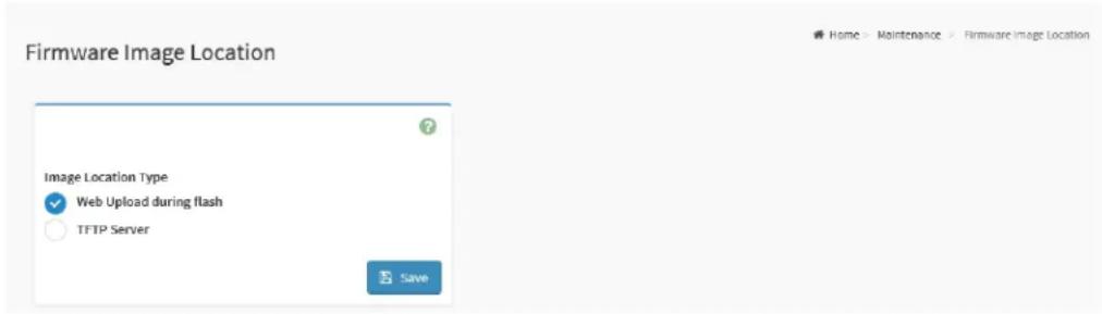
text_image
Firmware Image Location Image Location Type ✓ Web Upload during flash ○ TFTP Server SaveThe fields on the Firmware Image Location page include
- Image Location Type: To select the type of transfer the firmware image into the BMC either Web Upload during flash or TFTP Server.
■ Web Upload during flash: Transfer firmware image through web service.
■ TFTP Server: Transfer firmware image through TFTP protocol.
◆ TFTP Server Address: To specify the address of TFTP server where the firmware image stored.
◆ TFTP Image Name: To specify the firmware image file name.
◆ TFTP Retry Count: To specify the number of times to be retried in case a transfer failure occurs.
- Save: To save the configured settings.
2.13.3 Firmware Update
Firmware Update page provides the option for users to update the BMC firmware through BMC web service.
To view the Firmware Update page, click the Maintenance -> Firmware Update tab from the menu bar.
Figure 115. Snapshot of Firmware Update Page
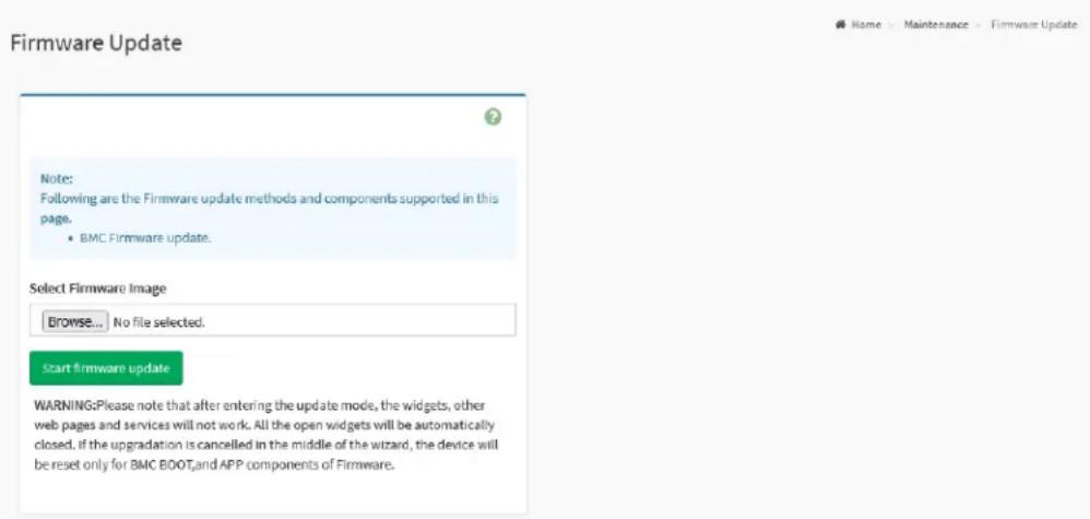
text_image
Firmware Update Note: Following are the Firmware update methods and components supported in this page. • BMC Firmware update. Select Firmware Image Browse... | No file selected. Start firmware update WARNING:Please note that after entering the update mode, the widgets, other web pages and services will not work. All the open widgets will be automatically closed. If the upgradation is cancelled in the middle of the wizard, the device will be reset only for BMC BOOTand APP components of Firmware.The fields on the Firmware Update page include
- Select Firmware Image: Click the Browse button to open file upload window, then select the to be updated BMC firmware image file.
- Start Firmware Update: Click the Start Firmware Update button to start the firmware update process.
2.13.4 BIOS Update
BIOS Update page provide the option for users to update host BIOS through BMC web service.
To view the BIOS Update page, click the Maintenance -> BIOS Update tab from the menu bar.
Figure 116. Snapshot of BIOS Update Page

text_image
BIOS Update Upgrade BIOS of the host. Please select BIOS Image and press 'Start BIOS update' to start the BIOS update procedure. Configuration Preserve BIOS configuration Option Flash BIOS after manually shutdown server Immediately flash BIOS without power action Immediately shutdown server to flash BIOS Select BIOS Image Browse... No file selected. Start BIOS updateThe fields on the BIOS Update page include
- Configuration
■ Preserve BIOS configuration: Click this option to preserve current BIOS configuration settings.
- Option
■ Flash BIOS after manually shutdown server: Select this option to waiting for manually shutdown server to flash BIOS firmware image.
■ Immediately flash BIOS without power action: Select this option to flash BIOS firmware image immediately.
- Immediately shutdown server to flash BIOS: Select this option to shutdown server immediately to flash BIOS firmware image.
- Select BIOS Image: Click the Browse button to open file upload window, then select the to be updated BIOS firmware image file.
- Start BIOS Update: Click Start BIOS Update button to start the BIOS update process.
2.13.5 PSU Update
PSU Update page provides the option for users to update the PSU firmware through BMC web service.
To view the PSU Update page, click the Maintenance -> PSU Update tab from the menu bar.
Figure 117. Snapshot of PSU Update Page
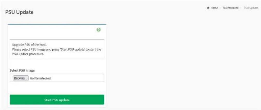
text_image
PSU Update Upgrade PSU of the host. Please select PSU Image and press 'Start PSU update' to start the PSU update procedure. Select PSU Image Browse... No file selected. Start PSU updateThe fields on the PSU Update page include
- Select PSU Image: Click the Browse button to open file upload window, then select the to be updated PSU firmware image file.
- Start PSU Update: Click the Start PSU Update button to start the PSU firmware update process.
2.13.6 FPGA Update
FPGA Update page provides the option for users to update the FPGA firmware through BMC web service.
To view the FPGA Update page, click the Maintenance -> FPGA Update tab from the menu bar.
Figure 118. Snapshot of FPGA Update Page

text_image
FPGA Update Upgrade FPGA of the host. Please select FPGA image and press 'Start FPGA update' to start the FPGA update procedure. Select FPGA Image Browse... No file selected. Start FPGA updateThe fields on the FPGA Update page include
- Select FPGA Image: Click the Browse button to open file upload window, then select the to be updated FPGA firmware image file.
- Start FPGA Update: Click the Start FPGA Update button to start the FPGA firmware update process.
2.13.7 Retimer Update
Retimer Update page provides the option for users to update the Retimer firmware through BMC web service.
To view the Retimer Update page, click the Maintenance -> Retimer Update tab from the menu bar.
Figure 119. Snapshot of Retimer Update Page

text_image
Retimer Update Upgrade retimer of the host. Please select retimer image and press 'Start retimer update' to start the retimer update procedure. Select retimer card to upgrade ○ PCIE Slot4 ○ PCIE Slot5 ○ PCIE Slot6 ○ PCIE Slot7 Select Retimer Image Browse... No file selected. Start retimer updateThe fields on the Retimer Update page include
- Select retimer card to upgrade: To select the to be updated re-timer device to flashing the firmware image.
- Select Retimer Image: Click the Browse button to open file upload window, then select the to be updated re-timer firmware image file.
- Start Retimer Update: Click the Start Retimer Update button to start the retimer firmware update process.
2.13.8 Backplane Update
Backplane Update page provides the option for users to update the Backplane firmware through BMC web service.
To view the Backplane Update page, click the Maintenance -> Backplane Update tab from the menu bar.
Figure 120. Snapshot of Backplane Update Page

text_image
BackPlane Update Upgrade backplane of the host. Please select backplane image and press 'start backplane update' to start the backplane update procedure. Select firmware type to upgrade Select interface to upgrade ○ Expander ○ MCU Select BackPlane Image Browse... No file selected. Start backplane updateThe fields on the Backplane Update page include
- Select firmware type to upgrade: To select the device that located on the backplane from the list, which to be updated firmware image.
- Select Backplane Image: Click the Browse button to open file upload window, then select the to be updated backplane firmware image file.
- Start Backplane Update: Click the Start Backplane Update button to start the Backplane firmware update process.
2.13.9 CPLD Update
CPLD Update page provides the option for users to update the CPLD firmware through BMC web service.
To view the CPLD Update page, click the Maintenance -> CPLD Update tab from the menu bar.
Figure 121. Snapshot of CPLD Update Page
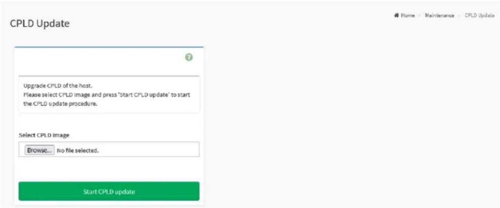
text_image
CPLD Update Upgrade CPLD of the host. Please select CPLD image and press 'Start CPLD update' to start the CPLD update procedure. Select CPLD Image Browse... No file selected. Start CPLD updateThe fields on the CPLD Update page include
- Select CPLD Image: Click the Browse button to open file upload window, then select the to be updated CPLD firmware image file.
- Start CPLD Update: Click the Start CPLD Update button to start the CPLD firmware update process.
2.13.10 Preserve Configuration
Preserve Configuration page provides various options for users to configure the to be preserved configuration settings while flashing BMC firmware image.
To view the Preserve Configuration page, click the Maintenance -> Preserve Configuration tab from the menu bar.
Figure 122. Snapshot of Preserve Configuration Page
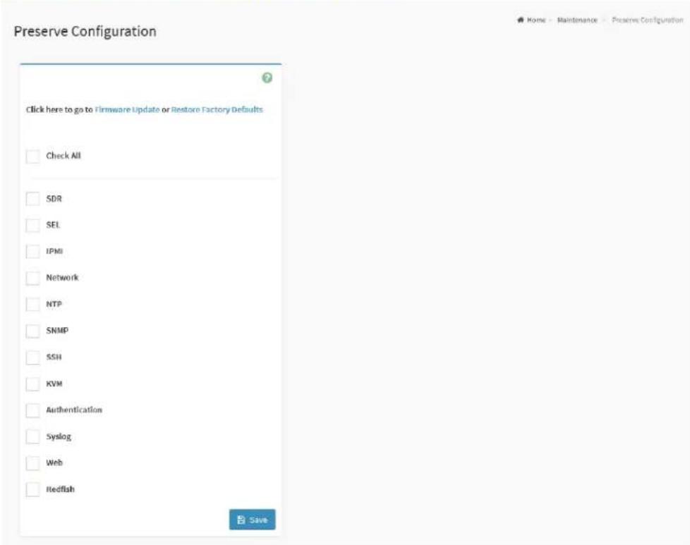
text_image
Preserve Configuration Click here to go to Firmware Update or Restore Factory Defaults Check All SDR SEL IPMI Network NTP SNMP SSH KVM Authentication Syslog Web Redfish SaveThe fields on the Preserve Configuration page include
- Check All: Click this option to select all configuration items listed on the page.
- SDR: Click this option to be preserve the SDR settings.
- SEL: Click this option to be preserve the SEL settings.
- IPMI: Click this option to be preserve the IPMI settings.
● Network: Click this option to be preserve the Network settings.
● NTP: Click this option to be preserve the NTP settings. -
SNMP: Click this option to be preserve the SNMP settings.
-
SSH: Click this option to be preserve the SSH settings.
● KVM: Click this option to be preserve the KVM settings. - Authentication: Click this option to be preserve the Authentication settings.
- Syslog: Click this option to be preserve the Syslog settings.
- Web: Click this option to be preserve the Web settings.
- Redfish: Click this option to be preserve the Redfish settings.
- Save: To save the configured settings.
2.13.11 Restore Configuration
Restore Configuration page provides the option for users to restoring configuration settings through BMC web service with the backup file. Users can generate the configuration backup file from the Backup Configuration page.
To view the Restore Configuration page, click the Maintenance ->Restore Configuration tab from the menu bar.
Figure 123. Snapshot of Restore Configuration Page
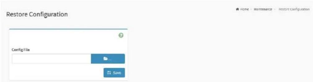
text_image
Restore Configuration Config File SaveThe fields on the Restore Configuration page include
- Config File: Click the Browse icon ( [icon] ) to open file upload window, then select the to be updated backup config file.
- Save: Click the Save button to start the restore configuration process.
2.13.12 Restore Factory Defaults
Restore Factory Defaults page provides various options for users to configure the preserve configurations, which will be preserved during the process of restore BMC firmware settings to the factory defaults.
To view the Restore Factory Defaults page, click the Maintenance ->Restore Factory Defaults tab from the menu bar.
Figure 124. Snapshot of Restore Factory Defaults Page
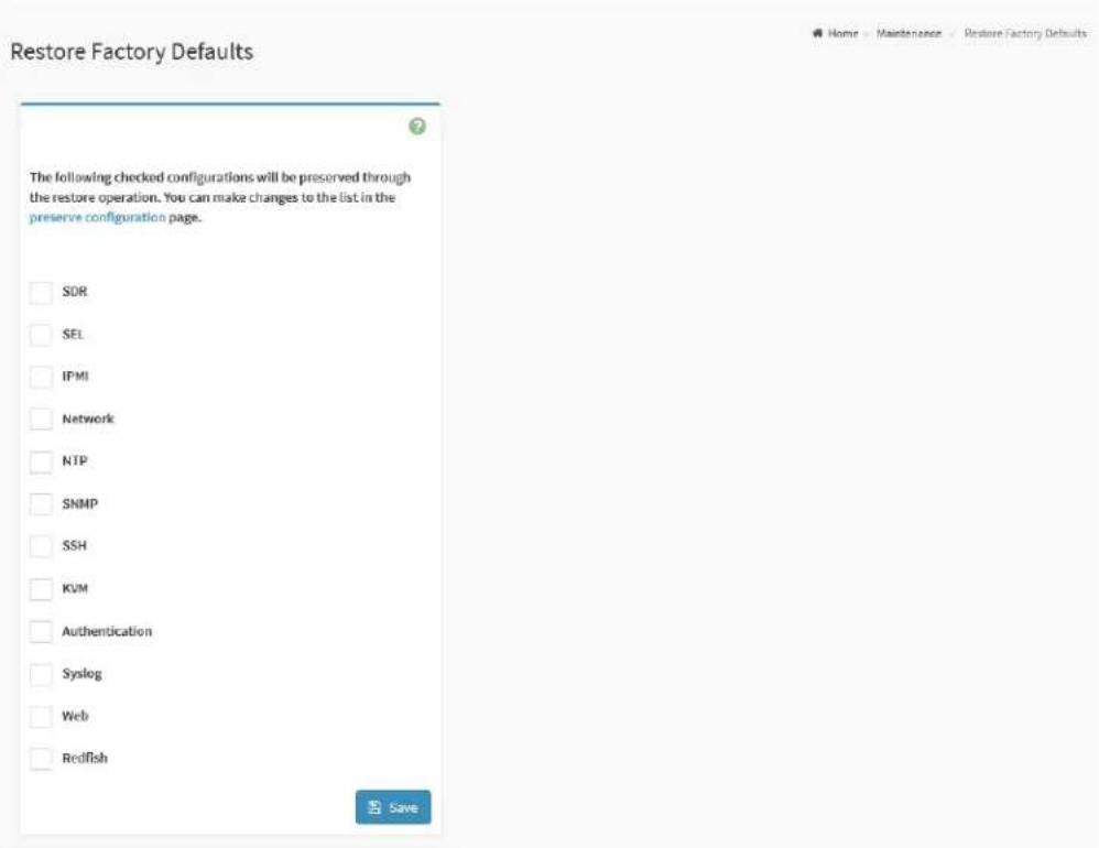
text_image
Restore Factory Defaults The following checked configurations will be preserved through the restore operation. You can make changes to the list in the preserve configuration page. SDR SEL IPMI Network NTP SNMP SSH KVM Authentication Syslog Web RedfishThe fields on the Restore Factory Defaults page include
- SDR: Click this option to preserve the SDR settings during restore factory defaults process.
- SEL: Click this option to preserve the SEL settings during restore factory defaults process.
- IPMI: Click this option to preserve the IPMI settings during restore factory defaults process.
● Network: Click this option to preserve the Network settings during
restore factory defaults process.
- NTP: Click this option to preserve the NTP settings during restore factory defaults process.
- SNMP: Click this option to preserve the SNMP settings during restore factory defaults process.
- SSH: Click this option to preserve the SSH settings during restore factory defaults process.
- KVM: Click this option to preserve the KVM settings during restore factory defaults process.
- Authentication: Click this option to preserve the Authentication settings during restore factory defaults process.
- Syslog: Click this option to preserve the Syslog settings during restore factory defaults process.
- Web: Click this option to preserve the Web settings during restore factory defaults process.
- Redfish: Click this option to preserve the Redfish settings during restore factory defaults process.
- Save: To perform the restore factory defaults process with configured settings.
2.13.13 Reset
Reset page provide the option for users to perform a BMC cold reset to reset the device.
To view the Reset page, click the Maintenance -> Reset tab from the menu bar.
Figure 125. Snapshot of Reset Page
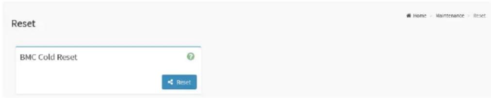
text_image
Reset BMC Cold Reset ResetThe fields on the Reset page include
- Reset: Click the Reset button to perform a BMC cold reset to reset the device.
2.14 Sign Out
To log out the BMC web service properly, click the Sign out button or tab is recommended.
To perform a sing out, click the Sign out tab from the menu bar or click the Sign out button from the current user window on the top right corner of the BMC WebUI screen.
Figure 126. Snapshot of Sign Out Button on the Current User Window

text_image
admin - Administrator Profile Sign out3.0 OEM IPMI Commands
This chapter provides the information of the OEM IPMI commands supported on BMC AST2500 controller of ASRock Rack mainboard
3.1 Supported OEM IPMI Commands
The Network Function (NetFN) of ASRock Rack OEM IPMI Commands is shown in the following:
- NetFn: 0x3A
The supported OEM IPMI Commands are listed in the following:
- 0x52 - Master Write Read
- 0x67 - Get Boot Complete
- 0x82 - Set Sensor Monitor
- 0x83 - Get Sensor Monitor
The details about each OEM IPMI command are listed in the following.
3.1.1 0x52 - Master Write Read
| Byte | Data Field | |
| Request Data | 1 | I2C Bus |
| 2 | Salve Address | |
| 3 | Read Count | |
| 4:N | Data Write (Up to 50 Bytes) | |
| Response Data | 1 | Completion Code |
| 2:N | Data Read |
3.1.2 0x67 - Get Boot Complete
| Byte | Data Field | |
| Request Data | - | - |
| Response Data | 1 | Completion Code |
| 2 | BMC Boot State00h = BMC is booting01h = BMC boot completed |
3.1.3 0x82 - Set Sensor Monitor
| Byte | Data Field | |
| Request Data | 1 | Sensor Monitor Config00h = Disable01h = Enable |
| Response Data | 1 | Completion Code |
3.1.4 0x83 - Get Sensor Monitor
| Byte | Data Field | |
| Request Data | - | - |
| Response Data | 1 | Completion Code |
| 2 | Sensor Monitor Config00h = Disable01h = Enable |
4.0 LED Indicator
This chapter provides the description of LED indicator on the mainboard which controlled by BMC.
4.1 BMC Heartbeat LED
The BMC Heartbeat LED Indicator is used to indicate the BMC firmware running status. The status behaviors are list below:
Table 1. BMC Heartbeat LED Status
| Color | Status | Description |
| Green | Solid Off | System AC power off.BMC firmware not running. |
| Solid On | System AC power on.BMC firmware is initializing.BMC firmware is updating firmware image. | |
| Slow Blinking (~1Hz) | BMC firmware is ready. | |
| Fast Blinking (~4Hz) | BMC firmware is running in manufacturing (MFG) mode. |
4.2 UID LED
The UID (Unit Identification) LED Indicator is used to locate the particular server system when it is deployed in the rack. It can help users to quickly identify a server system for maintenance.
Table 2. UID LED Status
| Color | Status | Description |
| Blue | Solid Off | Press the UID Button while UID LED is turn on.IPMI Chassis Identify command "Turn Off Identify". |
| Solid On | Press the UID Button while UID LED is turn off. | |
| IPMI Chassis Identify command "Force Identify On". | ||
| Blinking (~0.5Hz, keep about 8 seconds) | Trigger the action "Temporary On" from BMC Web UI for identify use.IPMI Chassis Identify command "Identify" |
4.3 System Fault LED
System Fault LED Indicator is used to indicate the system status while system in the failure status.
Table 3. System Fault LED Status
| Color | Status | Description |
| Amber | Solid Off | The following sensors are in de-asserted status:CPU PROCHOTCPU THERMTRIPCPU CATERRDRAM ErrorFAN |
| Solid On | The following sensors are in asserted status:CPU PROCHOTCPU THERMTRIPCPU CATERRDRAM ErrorFAN |
4.4 FAN Fault LED
FAN Fault LED Indicator is used to indicate the system FAN status.
Table 4. FAN Fault LED Status
| Color | Status | Description |
| Amber | Solid Off | The system FAN is running in normal. |
| Blinking (~1Hz) | The system FAN in failure status. E.g. system FAN is not running, system FAN speed is running lower/Higher than the sensor monitoring value or system FAN is removed while host is power on. |