MCA7004t - Speaker SoundTube - Free user manual and instructions
Find the device manual for free MCA7004t SoundTube in PDF.

User questions about MCA7004t SoundTube
0 question about this device. Answer the ones you know or ask your own.
Ask a new question about this device
Download the instructions for your Speaker in PDF format for free! Find your manual MCA7004t - SoundTube and take your electronic device back in hand. On this page are published all the documents necessary for the use of your device. MCA7004t by SoundTube.
USER MANUAL MCA7004t SoundTube
MCA7004t | MCA10004t | Install Instructions For: MCA7004t, MCA10004t
DANTE ENABLED NETWORKING AMPLIFIER INSTALLATION MANUAL
text_image
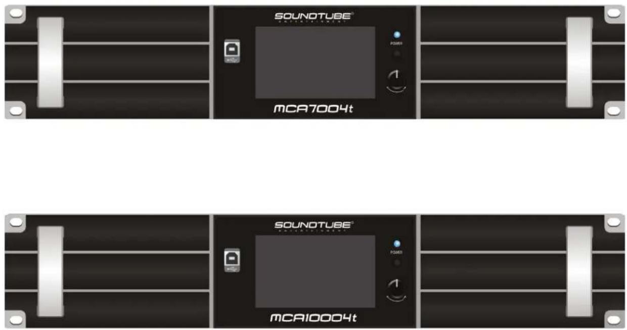
SOUNOTUBE® MCA7004t SOUNOTUBE® MCA10004t
Please read this user manual in detail before use.

Please consult the MCA7004t / MCA10004t Software Manual for instructions on how to use the STNet MCA Control PC Software. Manual can be found on the Downloads page at www.soundtube.com or on the MCA7004t or MCA10004t product webpages.

Warning Warning
SoundTube amplifiers must be installed by a professional audio installer/contractor. For safety and for optimum audio performance, installer must follow all directions issued by SoundTube Entertainment.

Do not spec or install amplifier near support beam, ventilation duct or other structure that may interfere with amplifier function or dispersion.
913.663.5600 | www.soundtube.com
CONTENT
- Product Description....3
1.1. Applicable Scenarios....3
1.2. Product Features....3
-
Technical Parameters ....4
-
Panel Layout....5
3.1. Front Panel 5
3.2. Rear Panel ....5
3.3. Display Panel....6
3.3.1 Homepage 6
3.3.2. Amplifier Settings Interface ....7
3.3.3. Input Settings Interface 8
3.3.4. Output Settings Interface 9
3.3.5. Channel Ganging Interface....10
3.3.6. Preset Settings Interface 10
3.3.7. Network IP Settings Interface 11
3.3.8. Details Interface....12
3.3.9. Device Connection 13
- Device Wiring Instructions 14
4.1 Power Cable 14
4.2 Wiring Notes....14
4.3 MATRIX Mode 14
4.4 BRIDGE Mode....15
-
Mounting Instructions....15
-
Precautions....16
1. Product Description
The SOUNDTUBE ENTERTAINMENT MCA7004t and MCA10004t multichannel amplifiers are Dante enabled and allow for fixed resistance and fixed voltage output modes. At 4 ohms, these amplifiers offer 700W and 1000W per channel, respectively. The 4.3" LCD touchscreen on the front panel allows for easy access to gain controls, input matrixing, and output mode selection. The STNet MCA Control software (included) provides the user with complete control over the amplifier. This software enables the user to monitor the real-time status of the amplifier and set up various DSP functions in real time. These DSP features include functions such as compressor, limiter, noise gate, parametric equalization, matrix router, delay, and more!
1.1. Applicable Scenarios
- Performing arts centers • Theatres • House of Worship
• Gymnasiums • Hotels • Sports Venues - Convention Centers • Shopping Malls • Night Clubs
• Retail Stores • Restaurants
1.2. Product Features
- Standard 19-inch chassis design with a height of 2U.
- The high-efficiency switching power supply, coupled with PFC, and class D digital amplifier technology deliver extremely low output distortion and high efficiency.
- The high-end DSP allows for built-in functions such as compressor, limiter, FIR processor, noise gate, parametric equalizer, matrix router, delay, high and low pass filtering, and other DSP functions.
- The amplifier supports matrixed and bridged output modes. Matrix mode allows for four independent output channels, while bridged mode will combine two of the four channels and allow for 100V fixed voltage output or high wattage 8 ohm and 16 ohm outputs.
- Fixed voltage and fixed resistance modes: 4Ω, 8Ω, 16Ω, 70V, 100V,
- The front panel offers a 4.3-inch IPS display supporting capacitive touch control. Through the front panel display, the user can monitor items such as mains voltage and current, amplifier status, amplifier temperature, output mode, amplifier real-time voltage, current, and power, channel volume, and speaker impedance.
- The amplifier supports TCP/IP and allows for remote connection to the amplifier using the STNet MCA Control software.
- Adjustable Input Sensitivity Options: 2dBu/6dBu/12dBu, set through PC software or LCD screen.
- Supported Input Sources: Analog, AES3 digital audio, and Dante network. AES3 and Dante inputs will be ducked for an analog input on the same channel. Only channels A and C support AES3 digital audio input.
- The amplifier will automatically calculate the connected speaker's impedance and display the impedance on the front panel display and STNet MCA Control.
- The amplifier will enter standby when there is no input for 30 minutes. The amplifier will exit standby if input is applied, the power button is held, or the amplifier is commanded through the MCA STNet Control software. The amplifier supports entering and exiting standby remotely through the MCA STNet Control software. "Wake" time is approximately 5 seconds.
- The amplifier's network TCP/IP function can manage multiple devices and the network interface can be cascaded.
- The RS485 port can be utilized to support external control.
- Wide Voltage Operation: 110-240VAC.
913.663.5600 | www.soundtube.com
- Technical Parameters
| Model MCA7004t MCA10004t | ||
| Output Power(20-20KHz/THD≤1%) | Stereo/Matrix@16Ω×4: 250W×4Stereo/Matrix@8Ω×4: 500W×4Stereo/Matrix@4Ω×4: 700W×4Bridged @16Ω×2: 700W×2Bridged @8Ω×2: 1400W×2Fixed Voltage 70V@9.8Ω: 500W×4Bridge Fixed Voltage 100V@10Ω: 1000W×2 | Stereo/Matrix@16Ω×4: 350W×4Stereo/Matrix 8Ω×4: 700W×4Stereo/Matrix 4Ω×4: 1000W×4Bridged 16Ω×2: 1000W×2Bridged 8Ω×2: 2000W×2Fixed Voltage 70V@6.1Ω: 800W×4Bridge Fixed Voltage 100V@6.6Ω: 1500W×2 |
| Inputs Euroblock balanced / unbalanced, DANTE, and AES3 digital audio | ||
| Input Sensitivity 2dBu/6Bu/12dBu | ||
| Input Resistance 20kΩ balanced | ||
| Frequency Response(@1W power) | 20Hz-20KHz ±1dB | |
| THD+N (@1/8 power) ≤0.05% | ||
| SNR (A-weighted) ≥96dB | ||
| Damping Coefficient(@ 1KHz) | ≥200@ 8 ohms | |
| Isolation (@1KHz) ≥95dB | ||
| Protection Method | Over-current protection, DC protection, Short-circuit protection | |
| Indicator Light | Power, Protection, Distortion | |
| Cooling Method | Fan cooling | |
| Power Supply | ~110V 50Hz ~110V 60Hz~120V 50Hz ~120V 60Hz~220V 50Hz ~220V 60Hz~230V 50Hz ~230V 60Hz~240V 50Hz ~240V 60Hz | |
| Max Power Consumption(all channels driven, pink noise input) | 1020W | 1380W |
| 1/8 Power Consumption(all channels driven, pink noise input) | 720W | 1140W |
| Dimension (L×D×H) | 19"x 16.63"x3.47" (484×422.5×88mm) | |
| Weight | 23.3lbs (10.6Kg) | 23.3lbs (10.6Kg) |
913.663.5600 | www.soundtube.com
3. Panel Layout
3.1. Front Panel
text_image
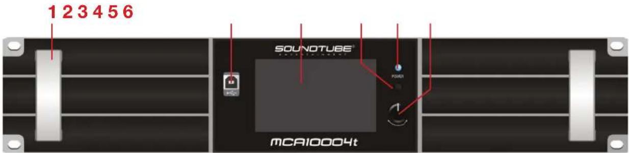
1 2 3 4 5 6 SOUNOTUBE® MCA10004t- Amplifi er handle.
- USB connection interface: reserved protocol connection interface.
- 4.3-inch IPS capacitive touch screen.
- Power switch: When the device is powered on, press and hold this button for 2 seconds to switch between standby and power-on status.
- Power indicator: BLUE: power on; ORANGE: standby.
- Gain adjustment knob and selection button: slow rotation for 0.5dB increment change, fast rotation for 5dB increment change.
3.2. Rear Panel
text_image
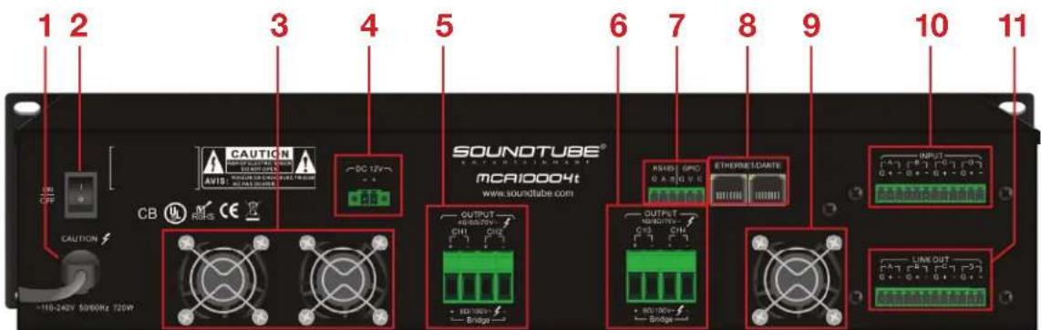
1 2 3 4 5 6 7 8 9 10 11 CAUTION AVIO: SOUND TUBE® SOUND TUBE® MCAI0004t www.soundtube.com OUTPUT +110-240V 5000Hz 720W Bridge RASSO GPC ETHERMELDARTE OUTPUT +110-240V 5000Hz 720W Bridge LINK OUT G+G+G+G+G+G+G+G+G+G+G+G+G+G+G+G+G+G+G+G+G+G+G+G+G+G+G+G+G+G+G+G+G+G+G+G+G+G+G+G+G+G+G+G+G+G+G+G+G+G+G CAUTION CB- AC input power cable.
- AC power switch: ON; OFF.
- Air outlet.
- 12V Power Supply Output.
- Amplifier output channels 1 and 2.
- Amplifi er output channels 3 and 4.
- GPIO interface (used by manufacturer only)/ RS485 interface: API control.
- Ethernet and Dante transmission interface. Both ports can be used to connect amplifier to STNet MCA Control and Dante audio transmission; which can be used to cascade multiple devices.
- Air outlet.
- Input channel A/B/C/D.
- LINK OUT: Parallel with the input channel, can be cascaded to the next amplifier.
913.663.5600 | www.soundtube.com
3.3. Display Panel
3.3.1. Homepage
124567

text_image
MCA10004t 1. Default 192.168.1.10 TP 60°C INPUT-dBu ANA ANA ANA ANA 2dBu 2dBu 2dBu 2dBu MUTE MUTE MUTE IN A IN B IN C IN D MATRIX MATRIX OUTPUT-V 0.0 dB 0 -10 -20 -30 -40 -50 -60 1 2 3 4 8 11 12 13- System Settings: Click the gear icon to enter the Input, Output, Channel Ganging, Presets, IP Settings, and Device Details menus. Click the home icon to return to the home page.
- Amplifier Settings: Click the amplifier settings icon to check the amplifier settings and amplifier status.
- Amplifier Status and Amplifier Temperature: When the amplifier status is normal, it will be displayed in gray. When one or more channel is faulty, the status will display "PROTECT". The temperature displayed is the highest temperature value among the four channels. The temperature will be displayed in degrees celcius.
- Device Name
- Current Preset: Displays the name of the currently loaded preset. A preset can be saved or loaded through the STNet MCA Control software. The amplifier's Preset page allows for presets to be loaded. Saving and deleting presets can only be done through the STNet MCA Control PC software.
- Device IP Address: The Ethernet IP address of the device is used for STNet MCA Control software connection. It can be modified through the IP Settings page.
- Standby Button: After clicking, the amplifier will enter standby. After entering standby, the screen will turn off and the power indicator will turn orange.
- Input Channel Level Indication: The maximum input signal is 20dBu. The display meter is set to an input sensitivity of 12dBu, and will NOT be changed even if the sensitivity is set to 2dBu/6dBu.
- Audio Input Type: This displays the current audio input source. ANA is analog input, AES is AES3 digital audio input, DAN is DANTE network audio input. You can select ANA, AES, DAN in the input source of the input interface. If ANA and DAN are input at the same time, the currently selected audio takes precedence.
- Audio Input Sensitivity: Select the appropriate input sensitivity according to the input source. Choices are 2dBu, 6dBu, and 12dBu, which can be selected in the sensitivity setting on the Input page.
913.663.5600 | www.soundtube.com
- Input Channel Gain Adjustment: Click to select the current channel, then adjust the gain by rotating the knob on the right side of the display. Adjustment ranges from -60db - +15db. Pressing the knob or the mute button will mute the channel.
- Output Level Display and Working Mode: This displays the output amplitude of the channel. When the output amplitude reaches around 90%, the blue light will light up and when the amplifier fails, the red light will light up; MATRIX is working in matrixed mode, BRIDGE is in bridged mode.
- Master Volume Adjustment: Controls the output of all four channels simultaneously. Click to select the master volume, then adjust the master volume gain by rotating the knob on the right side of the display. Adjustment ranges from -60db - +15db. Pressing the knob or the mute button will mute the channel.
3.3.2. Amplifier Settings Interface

- Limiter Switch: The limiter can be toggled on or off. When set to constant voltage mode, the limiter will be automatically turned on.
-
Mode Selection: Optional fixed resistance and fixed voltage modes
-
In matrix mode: 1) Fixed resistance 4 , 2) Fixed resistance 8 , 3) Fixed resistance 16 , 4) Fixed voltage 70V .
-
In bridge mode: 1) Fixed resistance 8 , 2) Fixed resistance 16 , 3) Fixed voltage 100V .
-
Output Channel Parameter Setting: This section is only enabled when the limiter is engaged. These values can be modified to limit the amplifier's output.
- Set output power (W), output voltage (V), output current (A): Click the value in the box, an input box will pop up, enter the value, click OK to complete the modification (when the input value exceeds the upper limit of this parameter, the maximum value will prevail). If you do not make changes, click ESC to exit. When modifying one of the parameters, the other parameters will change correspondingly according to the selected load impedance.
913.663.5600 | www.soundtube.com
- Set load impedance (Ω): Click the dropdown symbol to select the same impedance value as the speaker connected to the current channel. If there is no need to change the channel impedance, click the back button to exit. In constant voltage mode, fixed impedance cannot be selected.
-
Realtime Output Monitoring: You can view the peak clipping status, the fault status, the effective power, voltage, and current per each channel, in real time.
-
Output Channel Load Impedance: Displays the current channel impedance, which is detected when it is turned on or when the working mode is changed, but not in constant voltage mode.
3.3.3. Input Settings Interface
text_image
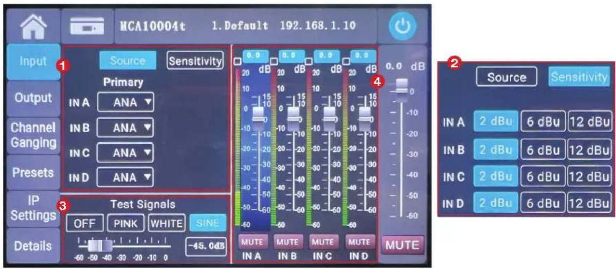
MCA10004t 1. Default 192.168.1.10 Input 1 Source Sensitivity Primary IN A ANA Channel Ganging IN B ANA IN C ANA Preset IN D ANA IP Settings 3 Test Signals OFF PINK WHITE SINE Details -45.0dB -60 -50 -40 -30 -20 -10 0 MUTE MUTE MUTE MUTE IN A IN B IN C IN D Source Sensitivity 4 2 IN A 2 dBu 6 dBu 12 dBu IN B 2 dBu 6 dBu 12 dBu IN C 2 dBu 6 dBu 12 dBu IN D 2 dBu 6 dBu 12 dBu- Input source selection: Click the dropdown symbol to select ANA (analog input), AES (AES3 digital audio input), or DAN (Dante audio input). A/B or C/D channel changes simultaneously when changing the input source; if you do not change the input source, click the back button to exit.
- Sensitivity adjustment: The sensitivity of the analog input can be set, and it supports 2dBu (about 1V), 6dBu (about 1.5V), and 12dBu (about 3V) sensitivity switching.
- Test signal: Pink (pink noise), white (white noise), sine (sine wave) signal output, click the test signal switch on, and the amplifier will output the corresponding signal. Slide the test signal volume slider to adjust the output volume. The Sine (sine wave) signal can be set to any frequency using the STNet MCA Control software. For details, please refer to the STNet MCA Control Manual.
- Input Channel Gain Adjustment: Click to select the current channel, then adjust the gain by rotating the knob on the right side of the display. Adjustment ranges from -60db - +15db. Pressing the knob or the mute button will mute the channel.
913.663.5600 | www.soundtube.com
3.3.4. Output Settings Interface

text_image
MCA10004t 1. Default 192.168.1.10 Input Output Channel Ganging Presets IP Settings Details Working Mode BRIDGE MATRIX A B C D ← OUT 1 A B C D ← OUT 2 BRIDGE MATRIX A B C D ← OUT 3 A B C D ← OUT 4 0.0 0.0 0.0 0.0 2 120 V 120 V 120 V 120 V 55 55 55 55 25 15 25 15 25 15 11 10 11 10 11 10 5 0 5 0 5 0 5 2 -10 2 -10 2 -10 2 -10 1 -20 1 -20 1 -20 1 -20 0.5 -30 0.5 -30 0.5 -30 0.5 -30 0.2 -40 0.2 -40 0.2 -40 0.2 -40 0.1 -50 0.1 -50 0.1 -50 0.1 -50 -60 -60 -60 -60 -60 MUTE MUTE MUTE MUTE MUTE OUT 1 OUT 2 OUT 3 OUT 4 0.0 dB -10 -20 -30 -40 -50 -60-
Working Mode and Matrix Routing Settings:
-
Working mode setting: BRIDGE sets the output to bridged mode; MATRIX sets the output to matrixed mode. When set to bridged mode, the OUT2 output interface and the OUT4 output interface are disabled. Please refer to the bridge connection diagram of OUT1/OUT3.
-
Matrix routing settings: Any input can be routed to any output via matrix selection.
-
Output Channel Gain Adjustment: Click to select the current channel, then adjust the gain by rotating the knob on the right side of the display. Adjustment ranges from -60db - +15db. Pressing the knob or the mute button will mute the channel.
913.663.5600 | www.soundtube.com
3.3.5. Channel Ganging Interface

text_image
MCA10004t 1. Default 192.168.1.10 Channel Ganging Input 1 INPUT Group 1 IN A IN B IN C IN D Group 2 IN A IN B IN C IN D OUTPUT 2 Group 1 OUT 1 OUT 2 OUT 3 OUT 4 Group 2 OUT 1 OUT 2 OUT 3 OUT 4 0.0 dB 0 -10 -20 -30 -40 -50 -60 Preset IP Settings Details MUTE- Input Channel Joint Adjustment: If set in the same group, the gain and mute status of input channels will be adjusted at the same time.
- Output Channel Joint Adjustment: If set in the same group, the gain and mute status of output channels will be adjusted at the same time.
- After the working mode is set to BRIDGE, the output channel of the device does not support channel joint adjustment.
3.3.6. Preset Settings Interface
text_image
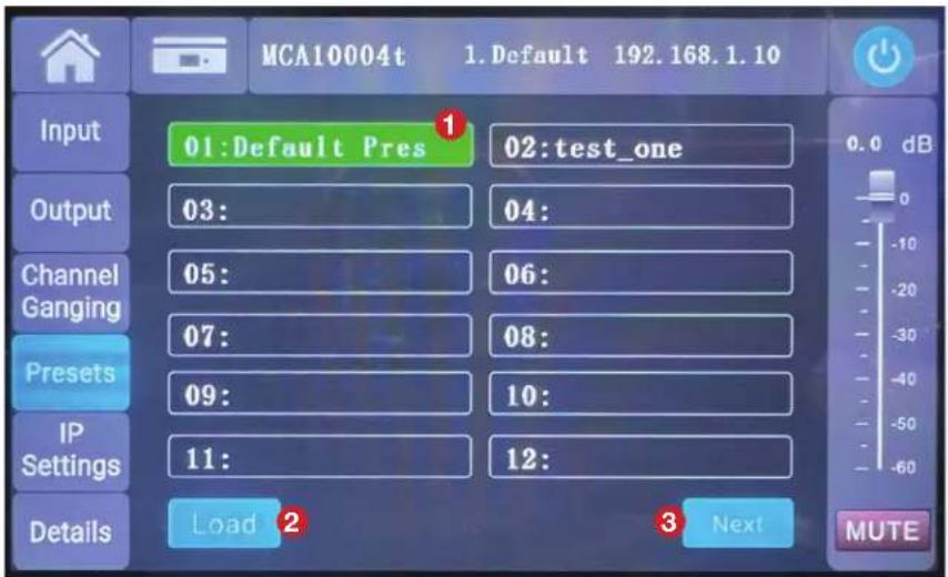
MCA10004t 1.Default 192.168.1.10 Input 01:Default Pres 02:test_one Output 03: 04: Channel 05: 06: Ganging 07: 08: Presets 09: 10: IP Settings 11: 12: Details Load 2 Next MUTE- The default preset cannot be deleted. Factory settings can be restored by loading this preset.
- To load a preset, click the desired preset, then click Load.
- Press "Next" to view additional Presets. Up to 79 presets can be saved.
Note: Presets can be saved and deleted on the PC interface. The touchscreen can only load presets.
913.663.5600 | www.soundtube.com
3.3.7. Network IP Settings Interface
text_image
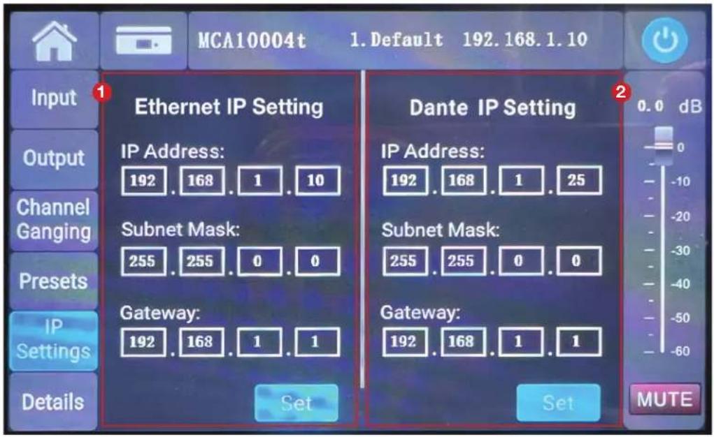
MCA10004t 1. Default 192.168.1.10 Input Ethernet IP Setting IP Address: 192 . 168 . 1 . 10 Subnet Mask: 255 . 255 . 0 . 0 Gateway: 192 . 168 . 1 . 1 Dante IP Setting IP Address: 192 . 168 . 1 . 25 Subnet Mask: 255 . 255 . 0 . 0 Gateway: 192 . 168 . 1 . 1 Set Set 0.0 dB 0 -10 -20 -30 -40 -50 -60 MUTE Channel Ganging Presets IP Settings Details- Ethernet IP Setting: IP address used for STNet MCA Control software connection. To change IP address, click the value to enter the input menu, enter the value, and click ok, then "Set".
- Dante IP Setting: IP address used for Dante network audio transmission. To change IP address, click the value to enter the input menu, enter the value, and click ok, then "Set".
913.663.5600 | www.soundtube.com
3.3.8. Details Interface
text_image
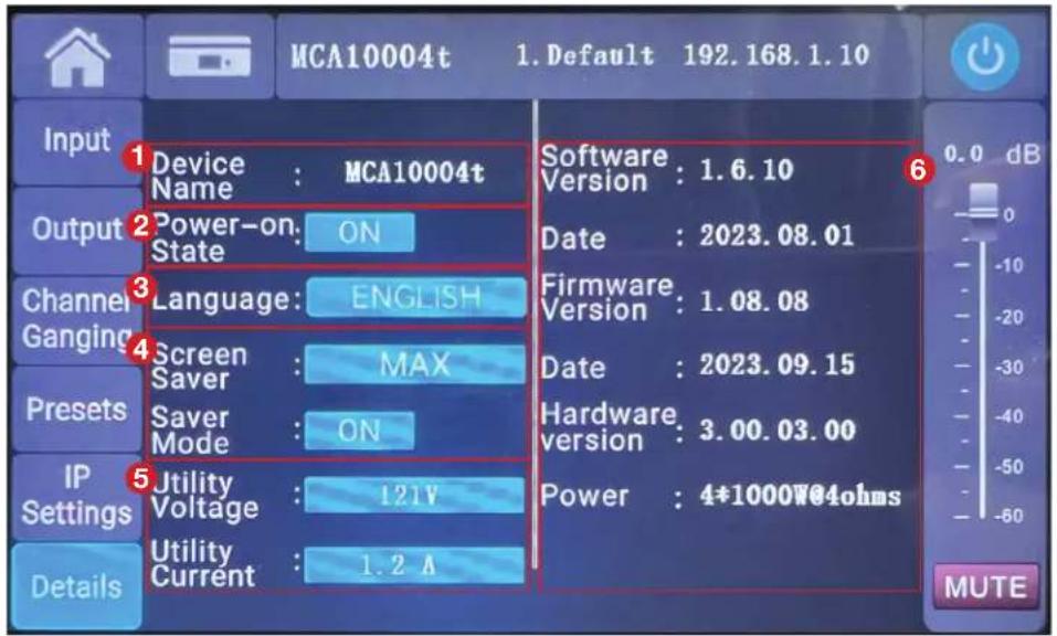
MCA10004t 1. Default 192.168.1.10 Input Device : MCA10004t Output Power-on: ON Channel Ganging Language: ENGLISH Screen Saver : MAX Presets Saver Mode : ON IP Settings Utility Voltage : 121V Details Utility Current : 1.2 A Software : 1.6.10 Date : 2023.08.01 Firmware : 1.08.08 Date : 2023.09.15 Hardware : 3.00.03.00 Power : 4*1000W@4ohms 0.0 dB MUTE- Device Name: The device display name is set to MCA7004t or MCA10004t by default. The device name can be modified by clicking the display name, then entering the desired name, and clicking "Complete" to complete the device name modification.
- Power-On State
- Language selection: Used to set the display language. Options are English or simplified Chinese.
- Screen Saver Time and Screen Saver Mode: Set the screen-off time of the display. Choices are 1 minute, 5 minutes, 10 minutes, and MAX (non-screen off). Screen saver mode is set to ON by default.
- Mains Voltage and Mains Current: Real-time display of the power supply voltage and current.
- Amplifier Information: Displays firmware information and device information.
3.3.9. Device Connection
bar
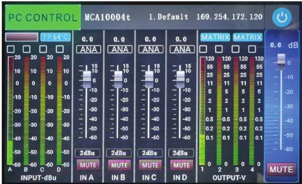
PC CONTROL MCA10004t 1. Default 169.254.172.120 | Channel | Level | | :--- | :--- | | INPUT-dBu A | -60 to 20 dB | | INPUT-dBu B | -60 to 20 dB | | INPUT-dBu C | -60 to 20 dB | | INPUT-dBu D | -60 to 20 dB | | 2dBu IN A | -60 to 15 dB | | 2dBu IN B | -60 to 15 dB | | 2dBu IN C | -60 to 15 dB | | 2dBu IN D | -60 to 15 dB | | OUTPUT-V 1 | -60 to 120 dB | | OUTPUT-V 2 | -60 to 120 dB | | OUTPUT-V 3 | -60 to 120 dB | | OUTPUT-V 4 | -60 to 120 dB | TP 54°C 0.0 ANA 0.0 ANA 0.0 ANA 0.0 ANA 0.0 ANA 0.0 ANA 0.0 ANA 0.0 ANA 0.0 ANA 0.0 ANA 0.0 ANA -10 to 15 dB -10 to 15 dB -10 to 15 dB -10 to 15 dB -10 to 15 dB -10 to 15 dB -10 to 15 dB -10 to 15 dB -10 to 15 dB -10 to 15 dB -10 to 15 dB -10 to 15 dBAfter connecting to the PC software through TCP/IP, "PC CONTROL" appears in the upper left corner of the screen interface, and the interface automatically jumps to the homepage. For PC operation, use STNet MCA Control software.
Note: The UI interface of the display screen is subject to upgrades and changes without prior notice. Please refer to the actual UI interface of the device.
913.663.5600 | www.soundtube.com
4. Device Wiring Instructions
4.1. Power Cable

The grounding end of the AC power cable shall be well grounded, otherwise there is a risk of electric shock!
The AC power cable must have sufficient over-current capability, the AC power voltage must be within ±10% of the nominal operating voltage of the device, and the AC power frequency must be within the nominal frequency range of the device (the nominal value is marked on the rear panel of the device).
4.2. Wiring Notes
Use shielded wires as much as possible for the input signal, the higher the shielding layer density, the better. The input signal should use balanced connection as far as possible to reduce noise interference. If using an unbalanced connection, the wire should be as short as possible, preferably no more than 10 ft (3 meters). Weak signal lines should not lay together with strong signal lines such as power lines or amplifi er output lines, otherwise noise may be generated. Turn off all equipment before changing any connections, as this may cause damage to your speakers.
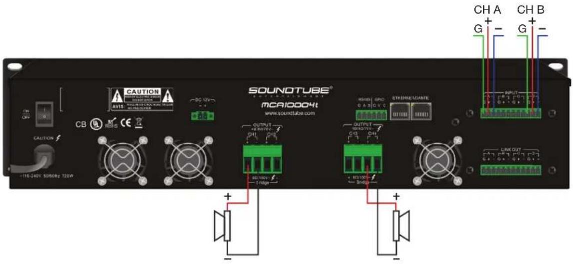
4.3. MATRIX Mode
text_image
CAUTION AVIS: SOUTUBE DC 12V CAUTION CB M RIGHS SOUNDTUBE® MCA10004t www.soundtube.com OUTPUT +10.50/75V CH1 CH2 -10Hz OUTPUT +10.50/75V CH1 CH2 -10Hz EThermostatante RESET GPO G A B C V C LINK OUT CH A G -10.50/75V -10Hz -10Hz -10Hz -10Hz -10Hz -10Hz -10Hz -10Hz -10Hz -10Hz -10Hz -10Hz -10Hz -10Hz -10Hz -10Hz -10Hz -10Hz -10Hz -10Hz -100A G -10.50/75V -10Hz -10Hz -10Hz -10Hz -10Hz -10Hz -10Hz -10Hz -10Hz -10Hz -10Hz -10Hz -10Hz -10Hz -10Hz -10Hz -10Hz -1T6-248X 5096MHz T20WIn matrix mode, any input can be routed to any output channel. In this example:
INPUT CH A --> OUTPUT CH1
INPUT CH B --> OUTPUT CH4
913.663.5600 | www.soundtube.com
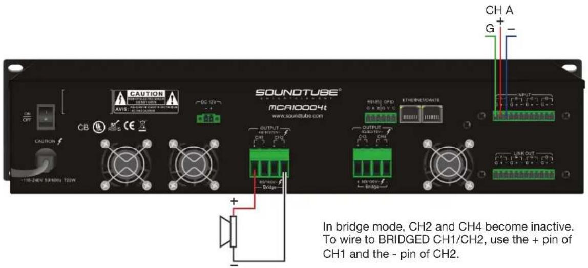
4.4. BRIDGE Mode
text_image
CAUTION AVIS: 11 V DC 12V -4 CAUTION CB MOS SOUNDTUBE® mCA10004t www.soundtube.com OUTPUT CH1 CH2 OUTPUT CH3 CH4 ETHERNETCANTES CH1/CH2/CH3 CH4/CH5/CH6 CH1/CH2/CH3 CH4/CH5/CH6 CH1/CH2/CH3 CH4/CH5/CH6 CH1/CH2/CH3 CH4/CH5/CH6 IN bridge mode, CH2 and CH4 become inactive. To wire to BRIDGED CH1/CH2, use the + pin of CH1 and the - pin of CH2.In bridge mode, CH2 and CH4 become inactive. To wire to BRIDGED CH1/CH2, use the + pin of CH1 and the - pin of CH2.
To wire to BRIDGED CH3/CH4, use the + pin of CH3 and the - pin of CH4.
In this example:
INPUT CH A --> BRIDGED CH1/CH2
5. Mounting Instructions
The MCA7004t and MCA10004t have rack mounting tabs on the front of the amplifi er faceplate. Use these tabs to install the amplifi er in standard 19" equipment racks. The MCA7004t and MCA10004t occupy two (2) standard rack unit positions each. Screws not included.
6. Precautions

Due to the high power density of this device and the strong magnetic field around it, please keep away from weak signal sensitive devices (preferably ≥ 20CM), otherwise noise may be generated.

Before installation, make sure that the power cable of the device is not connected to the power outlet; the power switch is turned off; the volume knob is fully closed (turn counterclockwise to the limit).
Although the amplifier will be protected under abnormal conditions, to achieve the best performance and highest safety of the amplifier, please pay attention to:
- Before use, the amplifier needs to be configured, including the connection of input and output lines. Improper wiring can cause the device to not work properly.
- Be careful when making connections, selecting input signals, and controlling output levels, as this can avoid unnecessary troubles.
- Do not short-circuit the ground wire of the output cable and the ground wire of the input signal. This will create a ground loop and cause oscillations.
- Never connect the output terminal to power, battery, or mains. Failure to do so may result in electric shock.
- Tampering with the circuit and unauthorized modification of the circuit is dangerous and invalidates all services provided by the manufacturer.
- Do not overload the mixer or it will send a clipped signal to the amplifier. The amplifier will accurately reproduce such signals and the speakers may be damaged.
- Do not use the amplifier below the nominal load. Too low a load can damage the speaker(s) by causing premature clipping and causing the amplifier to go into protection.
- After the amplifier is turned on and a signal passes through, there may be a fatal voltage on the output interface, please do not touch it with your hands or metal objects.
Heat dissipation instructions
The heat dissipation method of the device is as follows: cold air is sucked in from the front panel vent, flows through the heat sink inside and takes away the heat, and is discharged from the rear panel fan vent. To ensure good heat dissipation, please place the device in an environment of 0^ C – 40^ C, and make sure that the front and rear panel air ducts are unobstructed.
If the temperature of the heat sink inside the device exceeds 70^ C, the power limit function will be activated, and the output power of the amplifier will be reduced to avoid temperature rise. If the temperature of the radiator continues to rise above 85^ C, the amplifier output will be turned off. When the temperature drops to a safe temperature, the amplifier will automatically restart.
Statement of Design Changes
We reserve the right to change the design of any product at any time without notice and assume no obligation to make corresponding changes to previously manufactured products.
913.663.5600 | www.soundtube.com