
SKM-04-PLUS - KVM switch Smart-AVI - Free user manual and instructions
Find the device manual for free SKM-04-PLUS Smart-AVI in PDF.

| Product Type | 4-Port KM Switch with USB 2.0 Sharing |
| Dimensions | 12.57" W x 1.76" H x 6.69" D |
| Weight | 4.2 lbs |
| Power Adapter | External 100-240 VAC / 5VDC 2A @ 24W |
| USB Signal Type | USB 2.0, 1.1, and 1.0 with internal hub |
| CPU Ports | (4) USB Type B (female) |
| User Control Interface | (2) USB Type-A for keyboard/mouse; (2) USB Type-A for USB 2.0 transparent |
| Control Methods | Front panel buttons, keyboard hotkeys, RS-232 (115200 bps), OSD PASS, mouse gesture switching |
| Display Topology | Configurable via hotkeys [CTRL][CTRL]H[1-4] or GUI (up to 4 displays) |
| Absolute Mouse Mode | PASS technology for seamless cursor switching across displays |
| Relative Mouse Mode | Mouse gesture switching (double click scroll wheel + direction) |
| Emulation | Keyboard and mouse |
| Operating Temperature | +32 to +104°F (0 to +40°C) |
| Storage Temperature | -4 to 140°F (-20 to +60°C) |
| Humidity | 5 to 90% (non-condensing) |
| Approvals | UL, CE, ROHS compliant |
| Warranty | 1 year limited warranty |
| Box Contents | SKM-04-PLUS unit, 5VDC 2A power adapter, user manual |
| Country of Manufacture | USA |
| Software | Graphical User Interface (GUI) for configuration via PC, web browser, or Android app |
Frequently Asked Questions - SKM-04-PLUS Smart-AVI
User questions about SKM-04-PLUS Smart-AVI
0 question about this device. Answer the ones you know or ask your own.
Ask a new question about this device
Download the instructions for your KVM switch in PDF format for free! Find your manual SKM-04-PLUS - Smart-AVI and take your electronic device back in hand. On this page are published all the documents necessary for the use of your device. SKM-04-PLUS by Smart-AVI.
USER MANUAL SKM-04-PLUS Smart-AVI
4-PORT KM SWITCH WITH USB 2.0 WITH LAN

USER MANUAL

Designed and Manufactured in the USA
Smart-AM
1-800-284-2131
www.smartavi.com
OVERVIEW
TECHNICAL SPECIFICATIONS 3
WHAT'S IN THE BOX? 4
FRONT AND BACK 4
INSTALLATION 5
INITIAL SETUP 6
SYSTEM OPERATION 7
SETTINGS FILES 14
TROUBLESHOOTING 15
| USB | |
| Signal Type USB 2.0, 1.1, and 1.0 w/ internal hub | |
| CPU Ports (4) USB Type B (female) | |
| User Control Interface | (2) USB Type-A for keyboard and mouse connection only;(2) USB Type-A for USB 2.0 transparent |
| CONTROL | |
| Front Panel Buttons | |
| RS-232 Via Control @ 115200 bps | |
| Hot Keys Via Keyboard | |
| OSD PASS Technology and Mouse Gesture Switching | |
| OTHER | |
| Power Adapter External 100-240 VAC/5VDC2A @ 24W | |
| Dimensions 12.57" W x 1.76" H x 6.69" D | |
| Weight 4.2 lbs | |
| Approvals UL, CE, ROHS Compliant | |
| Operating Temperature +32 to +104°F (0 to +40°C) | |
| Storage Temperature | -4 to 140°F (-20 to +60°C) |
| Humidity | 5 to 90% (No Condensation) |
| Emulation | Keyboard and Mouse |
WHAT'S IN THE BOX?
| PART NO. Q-TY DESCRIPTION | ||
| SKM-04-PLUS 1 4-Port | KM Switch | with USB 2.0 Sharing |
| PS5VDC2A 1 5VDC 2A | (minimum) | power adapter with center-pin positive polarity. |
| 1 User | Manual | |
FRONT AND BACK

SKM-04-PLUS Back

SKM-04-PLUS Front
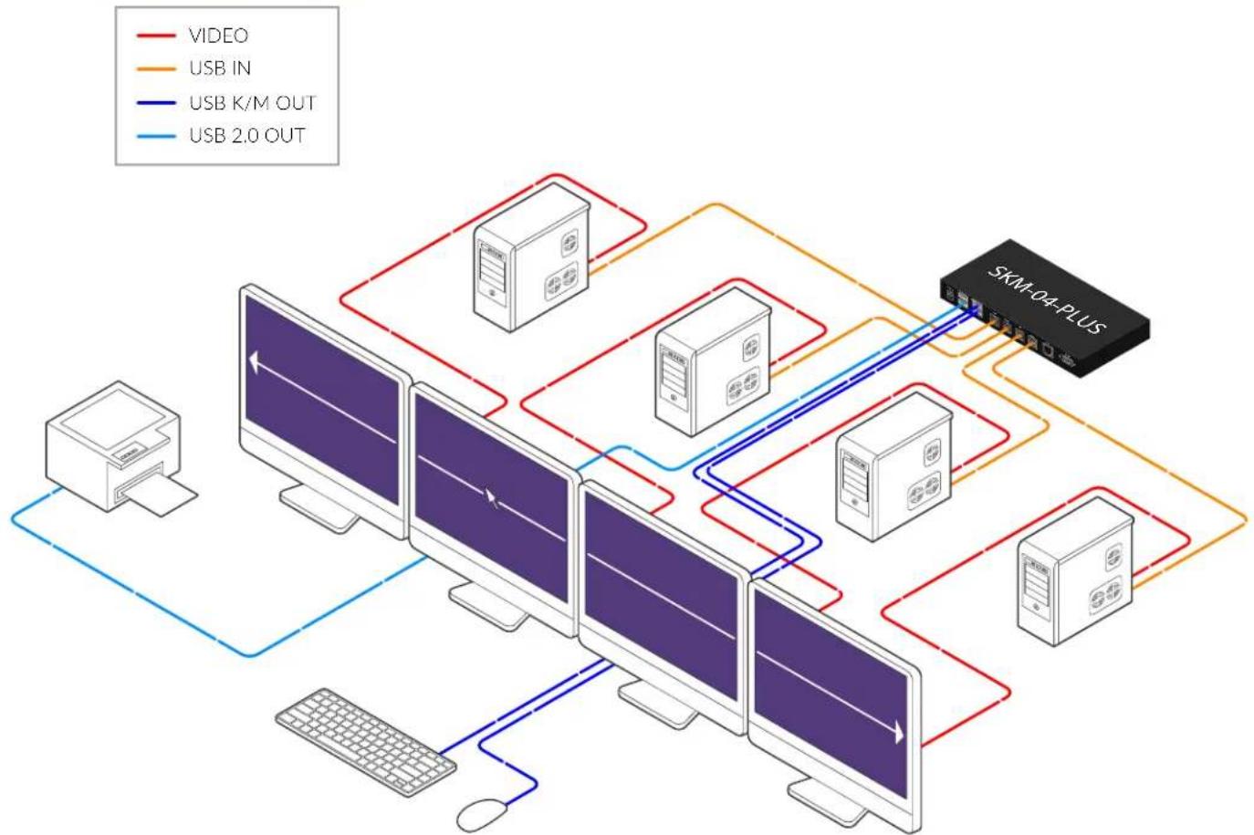
INSTALLATION
- Ensure that power is turned off or disconnected from the unit and the computers.
- Use a USB cable (Type-A to Type-B) to connect a USB port on each computer to the respective USB ports on the unit.
- Connect a USB keyboard and mouse in the two USB console ports.
- Power on the KM by connecting a 5VDC power supply to the power connector.
- Turn on all the computers.
Note: You can connect up to 4 computers to the 4 port KM.
Smart-AM
flowchart
graph TD
    A["Computer Monitor"] --> B["Video"]
    A --> C["USB IN"]
    A --> D["USB K/M OUT"]
    A --> E["USB 2.0 OUT"]
    B --> F["Desktop"]
    C --> G["Desktop"]
    D --> H["Desktop"]
    E --> I["Desktop"]
    F --> J["SKM-04-PLUS"]
    G --> J
    H --> J
    I --> J
    J --> K["User Interface"]
    style A fill:#f9f,stroke:#333
    style B fill:#ccf,stroke:#333
    style C fill:#ccf,stroke:#333
    style D fill:#ccf,stroke:#333
    style E fill:#ccf,stroke:#333
    style F fill:#dfd,stroke:#333
    style G fill:#dfd,stroke:#333
    style H fill:#dfd,stroke:#333
    style I fill:#dfd,stroke:#333
    style J fill:#dfd,stroke:#333
INITIAL SETUP
After all devices are connected to the SKM-04-PLUS, the user must choose a display topology configuration and display mode. By default, the SKM-04-PLUS is configured to a topology with four screens arranged horizontally starting with Port 1 on the left.
The installation setup must match one of SKM-04-PLUS's predefined display topology configurations. This can be selected through keyboard hotkey commands. Please refer to the "Display Topology Configuration" section for the available display topologies. Other configurations are possible through the GUI after initial setup.
ABSOLUTE MOUSE MODE KM SWITCHING
SmartAVI's new PASS (Progressive Automatic Screen Switching) technology allows seamless switching between computers by moving the mouse cursor from one display to another. With PASS, users can effortlessly switch computers for faster productivity. PASS only works in Absolute Mouse Mode.

flowchart
graph TD
    A["SOURCE 1"] -->|dashed arrow| B["SOURCE 2"]
    B -->|dashed arrow| C["SOURCE 3"]
    C -->|dashed arrow| D["SOURCE 4"]
    D -->|dashed arrow| E["SOURCE 4"]
    E -->|dashed arrow| F["SOURCE 3"]
    F -->|dashed arrow| G["SOURCE 1"]
    style A fill:#f9f,stroke:#333
    style B fill:#f9f,stroke:#333
    style C fill:#f9f,stroke:#333
    style D fill:#f9f,stroke:#333
    style E fill:#f9f,stroke:#333
    style F fill:#f9f,stroke:#333
    style G fill:#f9f,stroke:#333
RELATIVE MOUSE MODE KM SWITCHING
For using computers with multiple displays, SmartAVI developed a new feature called Mouse Gesture Switching, which is a technology that allows switching between computers using simple mouse clicks and gestures. No device driver is required. Simply press the scroll wheel twice and then move the mouse in the direction of the channel you desire to switch to. This feature only works in Relative Mouse Mode.

There are four ways to control the SKM-04-PLUS: front panel buttons, keyboard hotkeys, RS-232 serial commands, and through the included graphical user interface (GUI).
Front Panel Control
To switch to an input port, simply push the button on the front-panel of the KM. If an input port is selected, the LED of that port will turn on.
Front Panel - Port Selection LEDs:
| # STATUS DESCRIPTION | ||
| 1 OFF | Non-selected port | |
| 2 ON | Selected port | |
Hotkey Commands
A Hotkey command is a keyboard sequence used to trigger an action on the SKM-04-PLUS via the keyboard connected to the USB port of the SKM-04-PLUS. To activate the hotkey sequence, press the CTRL key twice and then enter the desired hotkey commands.
Note: All commands can use upper and/or lower case characters.
| COMMANDS HOTKEY | |
| Display Topology (multiple rows) | [CTRL] [CTRL] H [1-4] |
| Limit Input Ports (one row only) | [CTRL] [CTRL] W [1-4] |
| Cursor Rolling (roll past display borders up, down, left, and right) | [CTRL] [CTRL] 0 [0(OFF), 1(ON)] |
Note: Display Topology specifies the number of horizontal columns. The number of vertical rows is calculated in the software by 4/n columns.
Custom Hotkey Triggers
Users can customize the keys that trigger hotkeys. The default trigger for hotkey function on the keyboard is Ctrl + Ctrl. The trigger function can be used to change to the following keys:
Ctrl (Left / Right), Alt, Shift (Left / Right), Caps Lock, Scroll Lock, F1-F12
To view the current hotkey trigger setting:
Use the RS-232 command: / + / + ? + ? + Enter to view the current hotkey trigger. To reset the Hotkey Trigger, use the "Factory Defaults" command.
To change the hotkey trigger setting:
[hotkey] + [hotkey] + X + [desired hotkey]
Example: If the user's current hotkey trigger is Shift and they want to change it to Scroll Lock, the user would type Shift + Shift + X + Scroll Lock.
The SKM-04-PLUS may also be controlled via RS-232 commands. To use these commands, you must use HyperTerminal or an alternate terminal application. The settings for the connection are as follows: Baudrate 115200; Data Bits 8; Parity None; Stop Bits 1; Flow Control None.
Once you have connected to the SKM-04-PLUS via Serial, you will see the SKM-04-PLUS information when the device starts up.
The following commands can be used for RS-232 with available keyboard hotkeys:
COMMAND DESCRIPTION HOTKEY RS-232 COMMAND
| Switch All USB | [CTRL] [CTRL] [port #] [ENTER] //m | [port #] [ENTER] |
| Switch KM Only | [CTRL] [CTRL] c [port #] [ENTER] //c [port #] [ENTER] | |
| Switch USB Only | [CTRL] [CTRL] u [port #] [ENTER] //u [port #] [ENTER] | |
| Disable/Limit Ports | [CTRL] [CTRL] d [2-4] [ENTER] //d | [2-4] [ENTER] |
| Reset Software | [CTRL] [CTRL] r [ENTER] //r [ENTER] | |
| Factory Defaults | [CTRL] [CTRL] f [ENTER] //f [ENTER] | |
| Get Port Status | N/A //?? [ENTER] | |
| Switch resolutionChannel: 1-4Resolution:1 (1080p), 2 (4K), 3 (2K), 4 (720p) | N/A | //ce [SPACE] [SKM #][SPACE] [RESOLUTION #] |
| Mouse control speed (per resolution type)X and Y axes set in percent [0-500] | N/A | //mm [SPACE][resolution #] [SPACE][x #] [y #] |
| Get resolution/mouse info | N/A //r1 [ENTER] | |
Graphical User Interfaces
In addition to the front panel buttons, keyboard hotkeys, and RS-232 serial commands described above, the SKM-04-PLUS can be configured through simple GUIs that offer all the same customization options as the other control methods. These interfaces can be accessed on the connected computers, in a web browser, or in an Android app.
The SKM-04-PLUS has a configurable display topology that can be easily activated through keyboard hotkeys. No software or drivers are required to configure the display topology.
(1) Hotkey Command: "CTRL + CTRL + H + 4 + ENTER"
| 1234 |
(2) Hotkey Command: "CTRL + CTRL + H + 2 + ENTER"
| 1 | 2 |
| 3 | 4 |
(3) Hotkey Command: "CTRL + CTRL + H + 3 + ENTER"
| 123 | ||
| 4 | ||
(4) Hotkey Command: "CTRL + CTRL + H + 1 + ENTER"
| 1 |
| 2 |
| 3 |
| 4 |
With GUI
To reconfigure the display topology on the GUI,
- Click the Topology and Display button in the left pane.

If the display has not been previously configured, the default configuration will appear. The channels are color coded: yellow for Channel 1, green for Channel 2, blue for Channel 3, and red for Channel 4. The interface is click-and-drag.
- Move the tiles for the four channels into the desired positions on the grid.
- Click submit.

The GUI will display a dialog box to confirm that the topology has been updated.
Limit Input Ports Configuration
The SKM-04-PLUS allows the user to shut off input from specific connected computers without the need to disconnect them from the switch.
Note: Limit Input Ports commands reset the Display Topology configuration.
Hotkey Commands: CTRL, CTRL W (X) commands (allows one row only):
CTRL + CTRL + W + 4 + ENTER
| 1234 |
CTRL + CTRL + W + 3 + ENTER
| 123 |
Note: Port 4 N/A
CTRL + CTRL + W + 2 + ENTER
| 1 | 2 |
Note: Port 3, 4 N/A
CTRL + CTRL + W + 1 + ENTER
| 1 |
Note: Port 2-4 N/A
Note: Limit Input Ports commands reset Display Topology configuration.
SYSTEM OPERATION [CONTINUED]
With GUI
- Click the Configuration button in the left pane.

- Under USB Settings, use the Limit Ports dropdown menu to turn on or off the input from desired ports.

- Click Apply.
Resolution and mouse configuration only work in absolute mouse mode (//KS)
| DESCRIPTION RS-232 COMMAND | |
| Switch resolution | //ce [SPACE] [SKM #] [SPACE] [resolution #] [ENTER] |
| Mouse control speed (per resolution type) | //mm [SPACE] [resolution #] [SPACE] [x #] [SPACE] [y #] [ENTER] |
| Get resolution/mouse info | //r1 [ENTER] |
//CE [SPACE] [SKM #] [SPACE] [resolution #]
Where SKM channel can be set 1-4
Where Resolution number is the following:
- 1080p
2.4K
3.2K - 720p
For example: //CE 1 2
In this example we are setting channel 1 to reference 4K resolution.
//MM [SPACE] [resolution #] [SPACE] [x integer # (1-100)] [y integer # (1-100)]
For example: //MM 2 80 50
In this example we are setting the mouse movement according to 4K resolution with 80 as the mouse speed multiplier for X and 50 as the mouse speed multiplier for Y.
The integer number set for the mouse multiplier will act as a value from 1-100%.
In the example above we are using the following:
80 for X, therefore 80 will become 80% of the mouse movement moving horizontally on the X-axis 50 for Y, therefore 50 will become 50% of the mouse movement moving vertically on the Y-axis 100 will do 100%, 65 will do 65%, 5 will do 5%, etc.
Suppose you move the mouse 100 units for the X axis and 10 units for the Y axis. The software will change 100 * 80% = 80 units for the X axis and 10 * 50% = 5 unit for the Y axis. This will cause the mouse cursor to move slower.
//RL will return the channel's current mouse multiplier percentage and the current resolution which will reference the resolution number mentioned in the //CE command.
- Click the Mouse Speed Settings button in the left pane.

Each channel is represented by a dropdown menu at the bottom of the center pane.


- Follow the formula outlined in the previous section to calculate the desired mouse settings for each channel.
- Click the X or Y axis for the desired channel and enter the mouse multiplier.
- Click Submit.
SETTINGS FILES
In addition to one-time adjustment of settings through any of the control methods, the user can establish a settings file through the GUI. This allows the user to restore a previous configuration with a single click instead of making each adjustment every time they log in.
Creating a Settings File
- Open the KM Configuration Tool.
- Adjust the display configuration to your preferred settings.
- Click "Create Settings File."

- This will open a standard dialogue box for saving a .txt file. Navigate to the desired folder and click Save.
Loading a Settings File
- Open the KM Configuration Tool.
- Click "Load Settings File."
- Select the desired settings file and click Open.
TROUBLESHOOTING
No Power
- Make sure that the power adapter is securely connected to the power connector of the unit.
- Check the output voltage of the power supply and make sure that the voltage value is around 5VDC.
- Replace the power supply.
No Video
- Check if all the video cables are connected properly.
- Connect the computer directly to the monitor to verify that your monitor and computer are functioning properly.
- Restart the computers.
Keyboard is not working
- Check if the keyboard is properly connected to the unit.
- Check if the USB cables connecting the unit and the computers are properly connected.
- Try connecting the USB on the computer to a different port.
- Make sure that the keyboard works when directly connected to the computer.
- Replace the keyboard.
Mouse is not working
- Check if the mouse is properly connected to the unit.
- Try connecting the USB on the computer to a different port.
- Make sure that the mouse works when directly connected to the computer.
- Replace the mouse.
TECHNICAL SUPPORT
For product inquiries, warranty questions, or technical questions, please contact info@smartavi.com.
LIMITED WARRANTY STATEMENT
A. Extent of limited warranty
SmartAVI, Inc. warrants to the end-user customers that the SmartAVI product specified above will be free from defects in materials and workmanship for the duration of 1 year, which duration begins on the date of purchase by the customer. Customer is responsible for maintaining proof of date of purchase.
SmartAVI limited warranty covers only those defects which arise as a result of normal use of the product, and do not apply to any:
a. Improper or inadequate maintenance or modifications
b. Operations outside product specifications
c. Mechanical abuse and exposure to severe conditions
If SmartAVI receives, during applicable warranty period, a notice of defect, SmartAVI will at its discretion replace or repair defective product. If SmartAVI is unable to replace or repair defective product covered by the SmartAVI warranty within reasonable period of time, SmartAVI shall refund the cost of the product.
SmartAVI shall have no obligation to repair, replace or refund unit until customer returns defective product to SmartAVI.
Any replacement product could be new or like new, provided that it has functionality at least equal to that of the product being replaced.
SmartAVI limited warranty is valid in any country where the covered product is distributed by SmartAVI.
B. Limitations of warranty
To the extant allowed by local law, neither SmartAVI nor its third party suppliers make any other warranty or condition of any kind whether expressed or implied with respect to the SmartAVI product, and specifically disclaim implied warranties or conditions of merchantability, satisfactory quality, and fitness for a particular purpose.
C. Limitations of liability
To the extent allowed by local law the remedies provided in this warranty statement are the customers sole and exclusive remedies.
To the extant allowed by local law, except for the obligations specifically set forth in this warranty statement, in no event will SmartAVI or its third party suppliers be liable for direct, indirect, special, incidental, or consequential damages whether based on contract, tort or any other legal theory and whether advised of the possibility of such damages.
D. Local law
To the extent that this warranty statement is inconsistent with local law, this warranty statement shall be considered modified to be consistent with such law.
Smart-AM
SMART AUDIO VIDEO INNOVATION
NOTICE
The information contained in this document is subject to change without notice. SmartAVI makes no warranty of any kind with regard to this material, including but not limited to, implied warranties of merchantability and fitness for particular purpose. SmartAVI will not be liable for errors contained herein or for incidental or consequential damages in connection with the furnishing, performance or use of this material. No part of this document may be photocopied, reproduced, or translated into another language without prior written consent from SmartAVI, Inc.
20180109

Designed and Manufactured in the USA
Tel: (888) 994-7427 • (702) 800-0005
2455 W Cheyenne Ave, Suite 112
North Las Vegas, NV 89032
www.smartavi.com


- USER MANUAL
- Smart-AM
- OVERVIEW
- WHAT'S IN THE BOX?
- FRONT AND BACK
- INSTALLATION
- INITIAL SETUP
- ABSOLUTE MOUSE MODE KM SWITCHING
- RELATIVE MOUSE MODE KM SWITCHING
- Front Panel Control
- Hotkey Commands
- Custom Hotkey Triggers
- Graphical User Interfaces
- With GUI
- Limit Input Ports Configuration
- SYSTEM OPERATION [CONTINUED]
- SETTINGS FILES
- Creating a Settings File
- Loading a Settings File
- TROUBLESHOOTING
- No Power
- No Video
- Keyboard is not working
- Mouse is not working
- TECHNICAL SUPPORT
- LIMITED WARRANTY STATEMENT
- Extent of limited warranty
- Limitations of warranty
- Limitations of liability
- Local law
- SMART AUDIO VIDEO INNOVATION
- NOTICE
- Designed and Manufactured in the USA
Brand : Smart-AVI
Model : SKM-04-PLUS
Category : KVM switch