DS-2CE17U0T-LF - Security Camera Hikvision - Free user manual and instructions
Find the device manual for free DS-2CE17U0T-LF Hikvision in PDF.

User questions about DS-2CE17U0T-LF Hikvision
0 question about this device. Answer the ones you know or ask your own.
Ask a new question about this device
Download the instructions for your Security Camera in PDF format for free! Find your manual DS-2CE17U0T-LF - Hikvision and take your electronic device back in hand. On this page are published all the documents necessary for the use of your device. DS-2CE17U0T-LF by Hikvision.
USER MANUAL DS-2CE17U0T-LF Hikvision
Smart Hybrid Light Bullet & Turret Camera
User Manual
User Manual
Thank you for purchasing our product. If there are any quesons, or requests, do not hesitate to contact the dealer.
This manual applies to the models below:
| Type | Model |
| Type I Camera | DS-2CE16U0T-LPF |
| DS-2CE16U0T-LF | |
| Type II Camera | DS-2CE17U0T-LF |
| Type III Camera | DS-2CE76U0T-LPF |
| Type IV Camera | DS-2CE78U0T-LF |
| Type V Camera | DS-2CE76U0T-LMF |
This manual may contain several technical mistakes or prinng errors, and the content is subject to change without noce. The updates will be added to the new version of this manual. We will readily improve or update the products or procedures described in the manual.
01000020230816
© 2023 Hangzhou Hikvision Digital Technology Co., Ltd. All rights reserved.
About this Manual
The Manual includes instrucons for using and managing the Product. Pictures, charts, images and all other informaon hereinaer are for descripon and explanaon only. The informaon contained in the Manual is subject to change, without noce, due to rmware updates or other reasons. Please nd the latest version of this Manual at the Hikvision website (hps://www.hikvision.com/).
Please use this Manual with the guidance and assistance of professionals trained in supporting the Product.
Trademarks
HIKVISION and other Hikvision's trademarks and
logos are the properes of Hikvision in various jurisdicons.
Other trademarks and logos menoned are the properes of their respective owners.
Disclaimer
TO THE MAXIMUM EXTENT PERMITTED BY APPLICABLE LAW, THIS MANUAL AND THE PRODUCT DESCRIBED, WITH ITS HARDWARE, SOFTWARE AND FIRMWARE, ARE PROVIDED "AS IS" AND "WITH ALL FAULTS AND ERRORS". HIKVISION MAKES NO WARRANTIES, EXPRESS OR IMPLIED, INCLUDING WITHOUT LIMITATION, MERCHANTABILITY, SATISFACTORY QUALITY, OR FITNESS FOR A PARTICULAR PURPOSE. THE USE OF THE PRODUCT BY YOU IS AT YOUR OWN RISK. IN NO EVENT WILL HIKVISION BE LIABLE TO YOU FOR ANY SPECIAL, CONSEQUENTIAL, INCIDENTAL, OR INDIRECT DAMAGES, INCLUDING, AMONG OTHERS, DAMAGES FOR LOSS OF BUSINESS PROFITS, BUSINESS INTERRUPTION, OR LOSS OF DATA, CORRUPTION OF SYSTEMS, OR LOSS OF DOCUMENTATION, WHETHER BASED ON BREACH OF CONTRACT, TORT (INCLUDING NEGLIGENCE), PRODUCT LIABILITY, OR OTHERWISE, IN CONNECTION WITH THE USE OF THE PRODUCT, EVEN IF HIKVISION HAS BEEN ADVISED OF THE POSSIBILITY OF SUCH DAMAGES OR LOSS.
YOU ACKNOWLEDGE THAT THE NATURE OF THE INTERNET PROVIDES FOR INHERENT SECURITY RISKS, AND HIKVISION SHALL NOT TAKE ANY RESPONSIBILITIES FOR ABNORMAL OPERATION, PRIVACY LEAKAGE OR OTHER DAMAGES RESULTING FROM CYBER-ATTACK, HACKER ATTACK, VIRUS INFECTION, OR OTHER INTERNET SECURITY RISKS; HOWEVER, HIKVISION WILL PROVIDE TIMELY TECHNICAL SUPPORT IF REQUIRED.
YOU AGREE TO USE THIS PRODUCT IN COMPLIANCE WITH ALL APPLICABLE LAWS, AND YOU ARE SOLELY RESPONSIBLE FOR ENSURING THAT YOUR USE CONFORMS TO THE APPLICABLE LAW. ESPECIALLY, YOU ARE RESPONSIBLE, FOR USING THIS PRODUCT IN A MANNER THAT DOES NOT INFRINGE ON THE RIGHTS OF THIRD PARTIES, INCLUDING WITHOUT LIMITATION, RIGHTS OF PUBLICITY, INTELLECTUAL PROPERTY RIGHTS, OR DATA PROTECTION AND OTHER PRIVACY RIGHTS. YOU SHALL NOT USE THIS PRODUCT FOR ANY PROHIBITED END-USES, INCLUDING THE DEVELOPMENT OR PRODUCTION OF WEAPONS OF MASS DESTRUCTION, THE DEVELOPMENT OR PRODUCTION OF CHEMICAL OR BIOLOGICAL WEAPONS, ANY ACTIVITIES IN THE CONTEXT RELATED TO ANY NUCLEAR EXPLOSIVE OR UNSAFE
NUCLEAR FUEL-CYCLE, OR IN SUPPORT OF HUMAN RIGHTS ABUSES.
IN THE EVENT OF ANY CONFLICTS BETWEEN THIS MANUAL AND THE APPLICABLE LAW, THE LATTER PREVAILS.
Regulatory Informaon
EU Compliance Statement

This product and - if applicable - the supplied accessories too are marked with "CE" and comply therefore with the applicable harmonized European standards
listed under the Directive 2014/30/EU (EMCD) and Directive 2011/65/EU (RoHS).
Note: The products with the input voltage of within 50 to 1000 VAC or 75 to 1500 VDC comply with Direcve 2014/35/EU (LVD), and the rest products comply with Direcve 2001/95/EC (GPSD). Please check the specific power supply informaon for reference.
Direcve 2012/19/EU (WEEE Direcve): Products marked with this symbol cannot be disposed of as unsorted municipal waste in the European Union. For proper recycling, return this product to your local supplier upon the purchase of equivalent
new equipment, or dispose of it at designated collecon points. For more informaon see: www.recyclethis.info.
Directive 2006/66/EC and its amendment 2013/56/EU (Battery Directive): This product contains a baery that cannot be disposed of as unsorted municipal waste in the European Union. See the product
documentaon for specic baery informaon. The baery is marked with this symbol, which may include leering to indicate cadmium (Cd), lead (Pb), or mercury (Hg). For proper recycling, return the baery to your supplier or to a designated collecon point. For more informaon see: www.recyclethis.info.
Industry Canada ICES-003 Compliance
This device meets the CAN ICES-3 (A)/NMB-3(A) standards requirements.
KC
This is a class A product. In a domesc environment this product may cause radio interference in which case the user may be required to take adequate measures.
Safety Instrucon
These instrucons are intended to ensure that user can use the product correctly to avoid danger or property loss.
The precauon measure is divided into "Warnings" and "Cauons".
Warnings: Serious injury or death may occur if any of the warnings are neglected.
Cauons: Injury or equipment damage may occur if any of the cauons are neglected.
 |  |
| Warnings Follow these safeguards to prevent serious injury or death. | Cauons Follow these precautions to prevent potential injury or material damage. |

Warnings
- In the use of the product, you must be in strict compliance with the electrical safety regulations of the naon and region.
- Input voltage should meet both the SELV (Safety Extra Low Voltage) and the Limited Power Source with 12 VDC according to the IEC60950-1 and IEC62368-1 standard. Refer to technical speciaons for detailed informaon.
- The socket-outlet shall be installed near the equipment and shall be easily accessible.
- An all-pole mains switch shall be incorporated in the electrical installaon of the building.
- Do not connect mulple devices to one power adapter to avoid over-heang or a re hazard caused by overload.
- Make sure that the plug is rmly connected to the power socket.
- If smoke, odor or noise rise from the device, turn o the power at once and unplug the power cord, and then contact the service center.
- Never aempt to disassemble the camera by unprofessional personal.

Cauons
- No naked ame sources, such as lighted candles, should be placed on the equipment.
- Install the equipment according to the instrucons in this manual.
- To prevent injury, this equipment must be securely aached to the oor/wall in accordance with the installaon instrucons.
- Do not drop the camera or subject it to physical shock.
- Do not touch senor modules with ngers.
- Do not place the camera in extremely hot, cold (the operang temperature shall be -40°C to 60°C), dusty or damp locaons, and do not expose it to high electromagnec radiaon.
- If cleaning is necessary, use clean cloth with a bit of ethanol and wipe it gently.
- Do not aim the camera at the sun or extra bright places.
- The sensor may be burned out by a laser beam, so when any laser equipment is in using, make sure that the surface of sensor will not be exposed to the laser beam.
- Do not expose the device to high electromagnec radiaon or extremely hot, cold, dusty or damp environment.
-
To avoid heat accumulaon, good venlaon is required for the operang environment.
-
Keep the camera away from liquid while in use for non-water-proof device.
- While in delivery, the camera shall be packed in its original packing, or packing of the same texture.
- The beam of the light at the distance of 200 mm is classified as Risk Group 1 (RG1). Possible hazardous opcal radiaon emied from this product.
- DO NOT stare at operang light source. May be harmful to the eyes.
- Wear appropriate eye protecon or turn on the supplement light only at a safe distance (0.25 m) or in the area that is not directly exposed to the light when installing or maintaining the device.
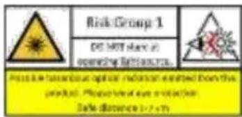
text_image
Risk Group 1 DE NOT share at operating SiteSource Please be dangerous about the incident entered from the product. Personal eye protection. Safe distance > 2 cm1 Introducon
1.1 Product Features
The main features are as follows:
• High performance CMOS sensor
- OSD menu with congorable parameters
- Smart light
• 3-axis adjustment
- Hybrid supplement light with IR and white light
1.2 Overview
1.2.1 Overview of Type I Camera

text_image
Switch Buon Power Cord Video Cable Bracket Main Body LensFigure 1-1 Overview of Type I Camera
Note:
Press and hold the switch buon for 5 seconds to switch the video output. Four kinds of video outputs are available: TVI, AHD, CVI, and CVBS.
1.2.2 Overview of Type II Camera

text_image
Switch Buon Power Cord Video Cable Bracket Main Body LensFigure 1-2 Overview of Type II Camera
Note:
Press and hold the switch buon for 5 seconds to switch the video output. Four kinds of video outputs are available: TVI, AHD, CVI, and CVBS.
1.2.3 Overview of Type III Camera
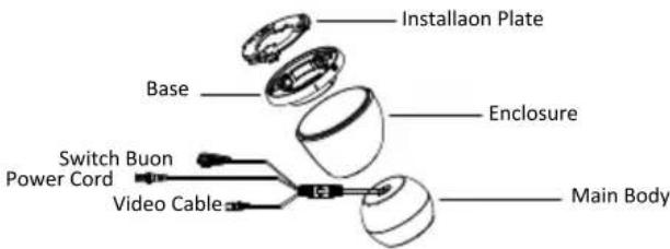
text_image
Installaoon Plate Base Enclosure Switch Buon Power Cord Video Cable Main BodyFigure 1-3 Overview of Type III Camera
Note:
Press and hold the switch buon for 5 seconds to switch the video output. Four kinds of video outputs are available: TVI, AHD, CVI, and CVBS.
1.2.4 Overview of Type IV Camera
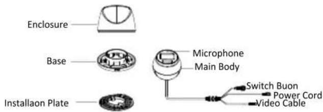
text_image
Enclosure Base Microphone Main Body Installaoon Plate Switch Buon Power Cord Video CableFigure 1-4 Overview of Type IV Camera
Note:
Press and hold the switch buon for 5 seconds to switch the video output. Four kinds of video outputs are available: TVI, AHD, CVI, and CVBS.
1.2.5 Overview of Type V Camera
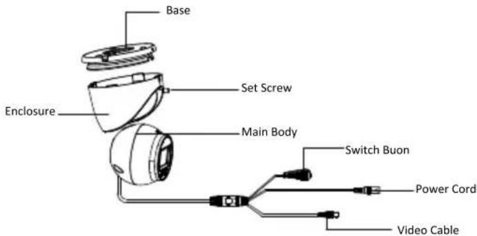
text_image
Base Enclosure Set Screw Main Body Switch Buon Power Cord Video CableFigure 1-5 Overview of Type V Camera
Notes:
Press and hold the switch buon for 5 seconds to switch the video output. Four kinds of video outputs are available: TVI, AHD, CVI, and CVBS.
2 Installaon
Before you start
- Make sure that the device in the package is in good condition and all the assembly parts are included.
- Make sure that all the related equipment is power-o during the installaon.
- Check the specicaon of the products for the installaon environment.
- Check whether the power supply is matched with your power output to avoid damage.
- Make sure the wall is strong enough to withstand three mes the weight of the camera and the mount.
- If the product does not funcon properly, contact your dealer or the nearest service center. DO NOT
disassemble the camera for repair or maintenance by yourself.
2.1 Installaon of Type I & II Camera
2.1.1 Ceiling/Wall Mounng without Juncon Box
Steps:
- Paste the drill template (supplied) to the installaon locaon.
- (Oponal) For cement ceiling, drill the screw holes with a 5.5 mm drill and insert the supplied wall plugs.
- (Oponal) Drill the cable hole, when the cables are routed through the ceiling.
- Secure the camera to ceiling with three PA4 × 25 screws (supplied).

natural_image
Technical line drawing of a surveillance camera with mounted sensor and base mount (no text or symbols)Figure 2-1 Secure the Camera to the Ceiling
- Connect the cables.
- Power on the camera to adjust the view angle according to the gure below.
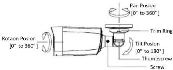
text_image
Pan Posion [0° to 360°] Trim Ring Tilt Posion [0° to 180°] Thumbscrew Screw Rotaon Posion [0° to 360°]Figure 2-2 3-Axis Adjustment
2.1.2 Ceiling/Wall Mounng with Juncon Box
Before you start:
- You need to purchase a juncon box in advance.
- Ceiling moung and wall moung are similar. Following steps take wall moung as an example.
Steps:
- Paste the drill template for juncon box to the installaon locaon.
- (Oponal) For cement wall, drill the screw holes with a 5.5 mm drill and insert the supplied wall plugs.
- (Oponal) Drill the cable hole, when the cables are routed through the wall.
- Take apart the juncon box.
- Fix the camera to the juncon box cover with three PM4 × 10 screws.

natural_image
Technical line drawing of a mechanical device with a flanged housing and central component (no text or symbols)Figure 2-3 Fix the Camera to the Juncon Box Cover
- Secure the juncon box body on the wall with three PA4 × 25 screws (supplied).

natural_image
Technical diagram of a mechanical component with internal gears and shafts, no visible text or symbolsFigure 2-4 Secure the Juncon Box on the Wall
-
Route the cables through the boom cable hole or side cable hole of the juncon box and connect the cables.
-
Fix the juncon box cover on its body with three PM3 × 16 L6 screws.
natural_image
Technical line drawing of a mechanical component with no visible text or symbolsFigure 2-5 Fix the Cover to Its Body
- Refer to Step 6 of 2.1.1 Ceiling/Wall Mounng without Juncon Box to nish installaon.
2.2 Installaon of Type III & IV Camera
2.2.1 Ceiling Mounng without Juncon Box
Steps:
- Paste the drill template (supplied) to the installaon locaon.
- (Oponal) For cement ceiling, drill the screw holes with a 5.5 mm drill and insert the supplied wall plugs.
- Install the camera to ceiling.
● For Type III and Type IV camera:
i. Secure the installaon plate to the ceiling with three PA4 × 25 screws (supplied).
ii. Fit the camera onto the installaon plate.
iii. Turn the camera as the gure below unl it snaps into the installaon plate.
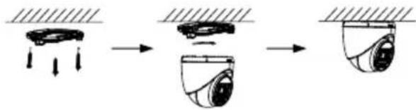
flowchart
graph LR
    A["Input Signal"] --> B["Sensor"]
    B --> C["Output Detection"]
Figure 2-6 Install the Camera to Ceiling
● For Type V camera:
i. Loosen the set screw.
ii. Rotate the camera to align the triangle mark with the screw hole, and dissemble the camera.
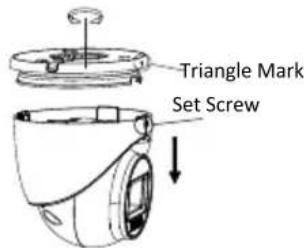
text_image
Triangle Mark Set ScrewFigure 2-7 Dissemble the Camera
iii. Secure the base to the ceiling with three PA4 × 25 screws (supplied).
iv. Align the screw hole with the triangle mark to install the camera back to the base and secure it.
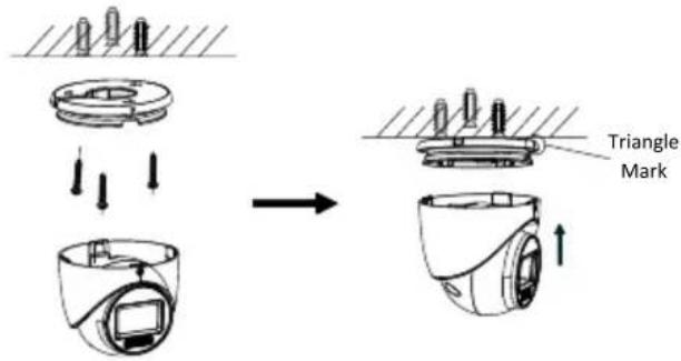
text_image
Diagram illustrating the process of a device's mounting or cleaning operation, showing steps from receipt to mark.Figure 2-8 Install the Camera to Ceiling
-
Connect the cables.
-
Power on the camera to adjust the view angle according to the gure below.
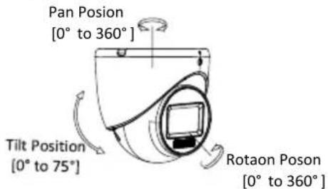
text_image
Pan Posion [0° to 360°] Tilt Position [0° to 75°] Rotaon Posion [0° to 360°]Figure 2-9 3-Axis Adjustment
1). Rotate the enclosure to adjust the pan posion [0° to 360°].
2). Move the main body up and down to adjust the lt posion [0° to 75°].
3). Rotate the main body to adjust the rotaon posion [0° to 360°].
2.2.2 Ceiling Mounng with Juncon Box
Before you start:
- You need to purchase a juncon box in advance.
- Ceiling mounng with a juncon box is similar to ceiling mounng with an inclined ceiling mount. Following steps take a juncon box as an example.
Steps:
- Loosen screws to take apart the juncon box.
- Paste the drill template for juncon box to the installaon locaon.
- (Oponal) For cement ceiling, drill the screw holes with a 5.5 mm drill and insert the supplied wall plugs.
- (Oponal) Drill the cable hole, when the cables are routed through the ceiling.
- Secure the juncon box body on the ceiling with three or four PA4 × 25 screws according to the actual object.
- Fix the camera to the juncon box.
● For Type IV camera:
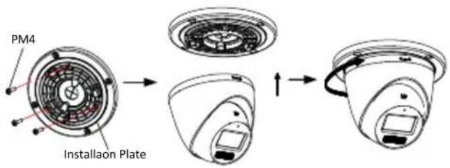
text_image
PM4 Installao PlateFigure 2-10 Fix the Camera to the Juncon Box Cover

natural_image
Diagram showing a device with internal components before and after assembly, no text or symbols presentFigure 2-11 Fix the Juncon Box Cover and Juncon Box Body
● For Type III and Type V camera:

flowchart
graph TD
    A["PA4 × 25 Juncon Box Cover"] --> B["Installaon Plate/Base"]
    B --> C["PM3 × 13"]
    C --> D["PM4/M4 × 10"]
    style A fill:#f9f,stroke:#333
    style B fill:#ccf,stroke:#333
    style C fill:#cfc,stroke:#333
    style D fill:#fcc,stroke:#333
Figure 2-12 Fix the Camera to the Juncon Box
- Route the cables through the boom cable hole or the side cable hole of the juncon box.
- Refer to step 5 of 2.2.1 Ceiling Mounng without Juncon Box to adjust the angle and nish the installaon.
2.2.3 Wall Mounng
Before you start:
You need to purchase a wall mount in advance.
Steps:
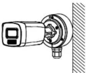
- Drill ∅10 mm screw holes in the wall where you want to install the wall mount.
- Use four M6 expansion bolts to x the wall mount onto the wall.
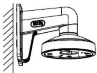
natural_image
Technical line drawing of a showerhead mounted on a wall-mounted fixture (no text or symbols)Figure 2-13 Fix the Wall Mount
- Fix the base/installaon plate to the wall mount.
● For Type III and Type IV camera:
i. Use three PM4 screws to x the installaon plate onto the wall mount.
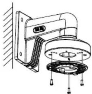
natural_image
Technical line drawing of a mechanical assembly with mounting bracket and housing (no text or symbols)Figure 2-14 Fix the Installaon Plate
● For Type V camera:
i. Refer to Step 3 of Secon 2.2.1 to dissemble the camera.
ii. Use M4 × 10 screws to x the base onto the wall mount.

natural_image
Technical line drawing of a mechanical assembly with mounting bracket and bearing housing (no text or symbols)Figure 2-15 Fix the Base
- Refer to steps 3 to 5 of Secon 2.2.1 Ceiling Mounng without Juncon Box to nish installaon.
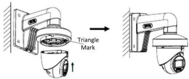
text_image
Triangle MarkFigure 2-16 Finish Installaon
3 Menu Descripon
Please follow the steps below to call the menu.
Note:
The actual display may vary with your camera model.
Steps:
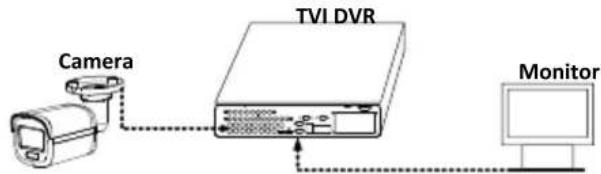
- Connect the camera with the TVI DVR and the monitor, as shown in gure 3-1.
text_image
Camera TVI DVR MonitorFigure 3-1 Connecon
- Power on the camera, TVI DVR, and monitor to view the image on the monitor.
- Click PTZ Control to enter the PTZ Control interface.
- Call the camera menu by clicking ☐ buon or calling preset No. 95.

flowchart
graph TD
    A["VIDEO FORMAT"] --> B["EXPOSURE"]
    B --> C1["EXPOSURE MODE"]
    B --> C2["AGC"]
    B --> C3["ANTI-BANDING"]
    B --> C4["BACK"]
    B --> C5["EXIT"]
    B --> C6["SAVE & EXIT"]

    A --> D["LIGHTING SETTINGS"]
    D --> E1["LIGHTING MODE"]
    D --> E2["IR/WHITE LIGHT"]
    D --> E3["SMART IR"]
    D --> E4["THRESHOLD"]
    D --> E5["LEVEL"]
    D --> E6["BACK"]
    D --> E7["EXIT"]
    D --> E8["SAVE & EXIT"]

    A --> F["VIDEO SETTINGS"]
    F --> G1["IMAGE MODE"]
    F --> G2["WHITE BALANCE"]
    F --> G3["BRIGHTNESS"]
    F --> G4["CONTRAST"]
    F --> G5["SHARPNESS"]
    F --> G6["SATURATION"]
    F --> G7["DNR"]
    F --> G8["BACK"]
    F --> G9["EXIT"]
    F --> G10["SAVE & EXIT"]

    A --> H["FACTORY DEFAULT"]
    H --> I["EXIT"]
    I --> J["SAVE & EXIT"]
Figure 3-2 Main Menu Overview
5. Click the direcon buons to control the camera.
1). Click up/down direcon buons to select menu opons.
2). Click Iris + to conrm the selecon.
3). Click le/right direcon buons to adjust the value of the selected opon.
3.1 VIDEO FORMAT
Video formats are available as below.
| Video Output | Video Format |
| TVI | 8 MP @12.5 fps8 MP @15 fps4 MP @25 fps4 MP @30 fps2 MP @25 fps2 MP @30 fps |
| AHD | 8 MP @12.5 fps8 MP @15 fps |
| CVI | |
| CVBS | PALNTSC |
3.2 EXPOSURE
EXPOSURE MODE
You can set the EXPOSURE MODE to GLOBAL, BLC, HLC, or DWDR.
- GLOBAL
GLOBAL refers to the normal exposure mode which adjusts lighng distribuon, variaons, and non-standard processing.
- BLC (Backlight Compensaon)
BLC (Backlight Compensaon) compensates light to the object in the front to make it clear, but this may cause over-exposure of the background where the light is strong.
• HLC (Highlight Compensaon)
HLC stands for highlight compensaon. The camera detects strong spots (over-exposure poron of image) and reduces the brightness of strong spots to improve the overall images.
- DWDR (Digital Wide Dynamic Range)
Digital wide dynamic range gives the camera the ability to view dark areas of the given image as well as extremely lighted porons of the image, or areas of high contrast.
AGC (Auto Gain Control)
It optimizes the clarity of the image in poor light conditions. The AGC level can be set to HIGH, MEDIUM, or LOW.
Note:
The noise will be amplified when seng the AGC level.
ANTI-BANDING
ANTI-BANDING is a camera seng that prevents the appearance of horizontal lines (banding) when photographing images in low frequency light and high brightness environments.
3.3 LIGHTING SETTINGS
LIGHTING MODE
IR and WHITE LIGHT are available.
IR
- IR LIGHT
You can turn on/o the IR LIGHT to meet the requirements of dierent circumstances.
- SMART IR
The Smart IR funcon is used to adjust the light to its most suitable intensity, and prevent the image from over exposure.
- D→N Threshold (Day to Night Threshold)
Day to Night Threshold is used to control the sensitivity of switching the day mode to the night mode. You can set the value from 1 to 9. The larger the value is, the more sensitive the camera is.
- N→D Threshold (Night to Day Threshold)
Night to Day Threshold is used to control the sensitivity of switching the night mode to the day mode. You can set the value from 1 to 9. The larger the value is, the more sensitive the camera is.
WHITE LIGHT
Under the WHITE LIGHT sub-menu, you can set the mode to OFF or AUTO.
- OFF
Set it to OFF to give up this funcon.
- AUTO
You can set THRESHOLD and LEVEL in this secon.
THRESHOLD
The higher the threshold is, the more sensitive the device is to dark environment.
LEVEL
You can adjust the maximum brightness of supplement light.
3.4 VIDEO SETTINGS
Move the cursor to VIDEO SETTINGS and click Iris+ to enter the submenu. IMAGE MODE, WHITE BALANCE, BRIGHTNESS, CONTRAST, SHARPNESS, SATURATION, and DNR are adjustable.
VIDEO SETTINGS
| IMAGE MODE | STD |
| WHITE BALANCE | |
| BRIGHTNESS | 5 |
| CONTRAST | 5 |
| SHARPNESS | 5 |
| SATURATION | 5 |
| DNR | 5 |
| BACK | |
| EXIT | |
| SAVE & EXIT |
Figure 3-3 VIDEO SETTINGS
IMAGE MODE
IMAGE MODE is used to adjust the image saturaon, and you can set it to STD (Standard), HIGH-SAT (High Saturaon), or HIGHLIGHT (beer indoor facial details).
WHITE BALANCE
White balance, the white rendition funcon of the camera, is to adjust the color temperature according to the environment. It can remove unrealisc color casts in the image. You can set WHITE BALANCE mode to AUTO or MANUAL.
MANUAL
You can set the R-GAIN/B-GAIN value to adjust the shades of red/blue color of the image.
WHITE BALANCE
| MODE | MANUAL |
| R-GAIN | 5 |
| B-GAIN | 5 |
| BACK | |
| EXIT | |
| SAVE&EXIT |
Figure 3-4 WHITE BALANCE
BRIGHTNESS
Brightness refers to the brightness of the image. You can set the brightness value from 1 to 9 to darken or brighten the image. The greater the value is, the brighter the image is.
CONTRAST
This feature enhances the dience in color and light between parts of an image.
SHARPNESS
Sharpness determines the amount of detail an imaging system can reproduce.
SATURATION
Saturaon is the properon of pure chromac color in the total color sensaon. Adjust this feature to change the saturaon of the color.
DNR
DNR refers to digital noise reducon. This funcon reduces noise in video stream.
3.5 FACTORY DEFAULT
Reset all the sengs except video format to factory defaults.
3.6 EXIT
Move the cursor to EXIT and click Iris+ to exit the menu.
3.7 SAVE & EXIT
Move the cursor to SAVE & EXIT and click Iris+ to save the sengs and exit the menu.
UD34644B-A